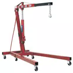
1 TONNE VIKING ENGINE CRANE
MODEL NO: PFC101S
Thank you for purchasing a Sealey product. Manufactured to a high standard, this product will, if used according to these instructions,
and properly maintained, give you years of trouble free performance.
IMPORTANT: PLEASE READ THESE INSTRUCTIONS CAREFULLY. NOTE THE SAFE OPERATIONAL REQUIREMENTS, WARNINGS & CAUTIONS. USE
THE PRODUCT CORRECTLY AND WITH CARE FOR THE PURPOSE FOR WHICH IT IS INTENDED. FAILURE TO DO SO MAY CAUSE DAMAGE AND/OR
PERSONAL INJURY AND WILL INVALIDATE THE WARRANTY. KEEP THESE INSTRUCTIONS SAFE FOR FUTURE USE.
1. SAFETY
9 Keep crane, lifting slings, support and beams in good working order and condition. Take immediate action to repair or replace damaged
parts by contacting your supplier. Ensure that all accessory lifting devices are suitably certified.
WARNING! If crane is damaged, remove from service immediately.
9 Ensure the surface on which the crane is used is level, firm and capable of supporting the weight of the crane with maximum load - we
recommend concrete. Never use the crane on tarmacadam or other soft surfaces.
9 Ensure the crane legs and arms are locked securely in position before use.
9 Keep children and unauthorised persons away from the working area.
9 Ensure the load is well balanced and its centre of gravity is within the working envelope of the crane (see Additional Specification).
9 Keep working area clean and tidy, free from unrelated materials and ensure that there is adequate lighting.
9 Ensure that load does not exceed the maximum lifting capacity of the crane. Overloading the crane is dangerous. Where appropriate, use
only the lifting points recommended by the manufacturer of the item to be lifted.
9 Before lifting the load ensure that the crane jib is in the lowest practical position, that there are no obstacles which may snag the load
whilst it is being lifted and that the area above the jib is clear.
9 To avoid injury, be fully aware of your own and other persons locations in relation to the lifting and lowering of the load.
9 Keep a sound footing and balance, and ensure the floor is not slippery.
9 Ensure jib extension is locked in position before lifting.
9 Ensure the centre of gravity always remains inside the crane base.
9 Ensuresucientclearanceofanyobstructionsisprovidedwhenusingorperforminginspection,maintenanceandcleaningandthatthe
area is well lit, clutter free and there are no trip or slip hazards.
8 DO NOT harness the load at an angle or use any attachments not verified as fit for purpose.
8 DO NOT allow the load to swing during lifting.
8 DO NOT allow the load to drop suddenly. Lower load with care, ensuring that you are fully aware of the condition of the surface onto
which the load is to be placed.
8 DO NOT load crane beyond its rated capacity for each specified jib extension position as indicated on the adhesive label. The capacity of
the crane reduces as the jib is extended.
8 DO NOT position any part of your body beneath the load.
8 DO NOT use the crane to move or transport a load other than for repositioning. The crane is a lifting device only.
8 DO NOT apply any sideways pressure to any part of the crane during lifting or when a load is suspended.
8 DO NOT attempt to adjust the safety valve, which has been set and sealed by the manufacturer.
8 DO NOT use this product to perform a task for which it is not designed.
8 DO NOT use whilst under the influence of drugs, alcohol or intoxicating medication.
8 DO NOT climb on the crane.
9 When not in use fold the crane down and store in a safe, dry, childproof area.
9 This crane is designed for lifting within a garage or workshop environment.
WARNING! Failure to heed safety and warning instructions may result in damage and/or personal injury and will invalidate the warranty.
2. INTRODUCTION
Thelegsfoldawayforstorageandtransportationandextendparalleltotaroundvariousobstructionslikepallets,boxes,etc.Handoperated
DeadMan’scontroltopreventaccidentallowering.Manuallycontrolleddescentspeed.Thejibcanbeextendedandlocksinvepositions
between960-1350mm.Thehydraulicunitandhandlerotatesby200°aidingusewherespaceislimited.Strongnylonandbreglasswheelsfront
andrear.Rearcastorwheelscomewithbrakes.Anadditionalwheelforeaseofmovementwhenfolded,allarenonoormarking.
PFC101S Issue 2 05/03/2024
Original Language Version
© Jack Sealey Limited
Refer to
instructions
Wear protective
gloves
Wear safety
footwear
Wear protective
clothing
DO NOT stand
under load
Lower
Ensure arm is locked in position
Sling loads correctly
Original Language Version
© Jack Sealey Limited
3. SPECIFICATION
Model No.................................................................PFC101S
Lifting Capacity Position 1.........................................1000kg
Lifting Capacity Position 2...........................................900kg
Lifting Capacity Position 3...........................................800kg
Lifting Capacity Position 4...........................................700kg
Lifting Capacity Position 5...........................................600kg
Max.LiftHt.atMax.JibExt.Position1...................2080mm
Max.LiftHt.atMax.JibExt.Position2...................2140mm
Max.LiftHt.atMax.JibExt.Position3...................2190mm
Max.LiftHt.atMax.JibExt.Position4...................2250mm
Max.LiftHt.atMax.JibExt.Position5...................2300mm
Length of Jib Position 1.............................................960mm
Length of Jib Position 2...........................................1053mm
Length of Jib Position 3...........................................1152mm
Length of Jib Position 4...........................................1250mm
Length of Jib Position 5...........................................1350mm
Height Jib Down......................................................1550mm
Length.....................................................................1600mm
Rear Width................................................................390mm
Width Inside Front Frame....................................... 1025mm
Width Front Frame...................................................1129mm
Height Legs Folded.................................................1550mm
Height of Frame.........................................................105mm
Minimum Leg Length...............................................1450mm
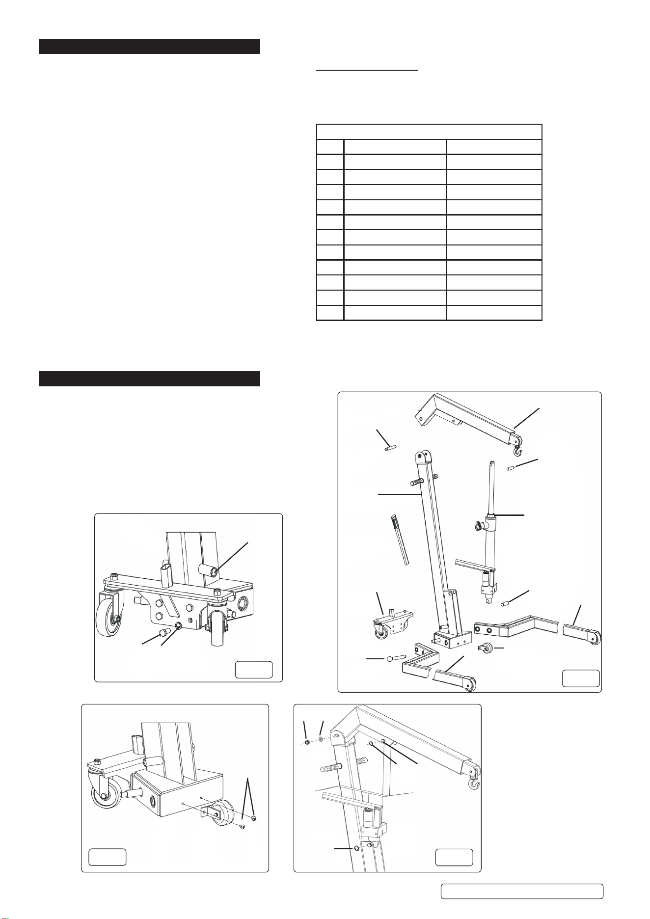
4. ASSEMBLY
NETT WEIGHT:
Refer to attached Parts list and g.1
4.1. It is essential to carry out the following assembly
processes with the help of other people.
4.2. Fix the rear wheel assembly (item 4) to the Main Post assy.
(item3)usingthehex.headscrew(seeg.2).
4.3. Fix the auxiliary wheel assembly (item 5) to the Main Post assy
(item3)usingtheroundheadscrews(seeg.3).
g.3
g.2
g.1
g.4
Additional Specication
Workingenvelopemm(WxDxH): 1160x1450x2300
Nett Weight: 96kg
Key to Fig.1
Item Description Parts List Item No.
1 Jib Assembly Supplied Assembled
2 Ram Assembly Supplied Assembled
3 Main Post Assembly 6
4 Rear Wheel Plate Assy. 10
5 Auxiliary Wheel 20
6 Front Leg Assy - left 16
7 Front Leg Assy - right 22
8 Axle 2
9 Leg Pin 15
10 Shaft Pin 8
11 Piston Rod Shaft 35
See Key above
See Parts List
See Parts List
See Parts List
12
13
1
8
2
10
9
4
3
4
3
9
21
36 35
7
11
6
5
8
Docking Stubs
PFC101S Issue 2 05/03/2024
Original Language Version
© Jack Sealey Limited
4.4. Locatetheparallellegsoneithersideoftheframebase,inserttheFrontLegLatchitem6(seediagrampage2ofpartslist)andxin
place using items 4, 5, and 7 (see diagram page 2 of parts list).
4.5. Mountthejibassembly(g.1item1)totheframeusingshaft(g.1item8)andxinpositionusingplainwasherandhexagonal
nutsandwashers(g.4items3and4).
4.6. Locatetheramassembly(g.1item2)intheframeusingshaftpin(g.1item10,g.4item9).Locktheshaftinpositionusingthecirclips
(g.4item8and9).
4.7. Locatethecylinderpistonrodinthejibusingtheshaft(g.1item11).Locktheshaftinpositionusingthecirclips(items36onpartslist)
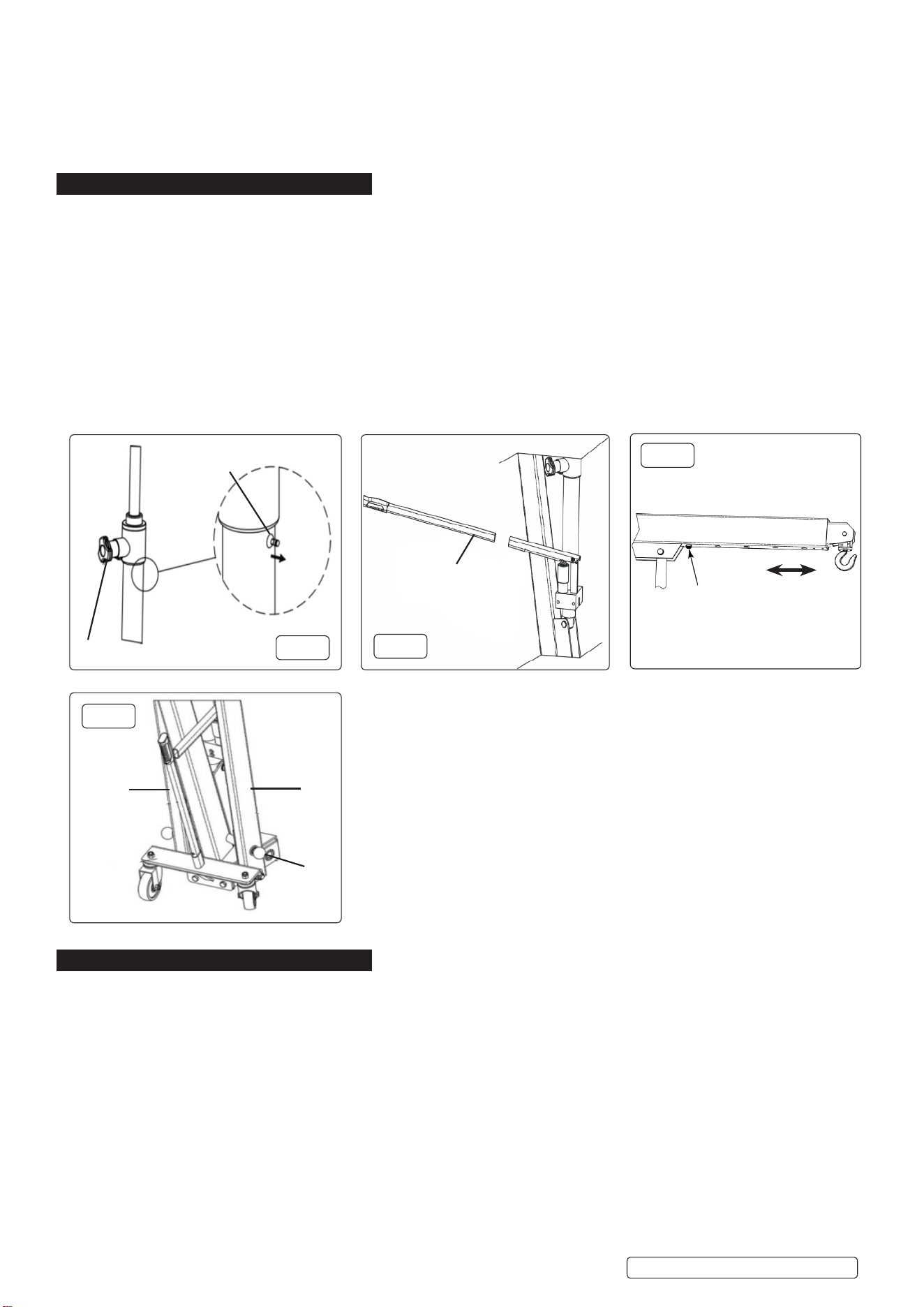
5. OPERATION
5.1. Prior to using the crane, the hydraulic circuit needs to be bled in order to eliminate any air from the system. Insert the operational
handle(g.6item7)intothemanifoldbody(seeg.6).
5.2. Tobleedthesystem,gentlyraisetheairbleedtap(g.5)andoperatetheleverforseveralstrokes.Pushtheairbleedtapbackwhen
the system has been bled of air.
5.3. To adjust the hook location, depress the spring loaded button on the underside of the jib and slide the extendable arm to its required
locationensuringthatthebuttonisfullylocatedandthatthearmissecurelylocated(seeg.7).
5.4. To lift the load, pump lever. If lifting an engine, secure it at the points recommended by the manufacturer.
5.5. Tolowertheload,turntheknobofthepressurereleasemechanism(g.5).Thissystemenablestheloweringtoberegulatedand
controlled manually and precisely. The crane will stop the lowering process when the knob is released i.e. ‘Deadman’s Control’.
5.6. When the crane is not in use the slide should be moved to its minimum length,and the piston of the hydraulic unit should be fully
retracted.
5.7. Whenstoringthecrane(g.8),lowerthejibtoitslowestpoint,removetheoperatingleverandthelockingpins(g.1,g.6).
5.8. Rotatethelegstothevertical,alignthepinholeswiththedockingstubs(g.2)andfullyandsecurelyinsertthelockingpins.Locate
theoperatinghandleintothedockingstubontherearwheelassembly(g.8).
6. MAINTENANCE
6.1. Ensuresucientclearanceofanyobstructionsisprovidedwhenperforminginspection,maintenanceandcleaningandthattheareais
well it, clutter free and there are no trip or slip hazards.
6.2. Themaintenanceandrepairofthiscranemayonlybecarriedoutbyqualiedandauthorizedpersonnel,whoasaresultoftheir
training and experience are familiar with the hydraulic systems used in these devices.
6.3. The crane shall be inspected regularly by professional personnel to check the wear of casters, handles and hooks, check whether the
sealisleaking,andwhetherthesafetyvalveisnormal,andconrmthatallsafetylabelsareintact,clearandeasytoread.
6.4. Every part of the crane should be checked daily for oil leakage, deformation, damage, etc.
6.5. It is necessary to lubricate the moving parts of the crane regularly.
6.6. This product uses ISO 15#, ISO 22# hydraulic oil, or other hydraulic oil of the same grade; DO NOTusebrakeuid!Oilvolumeis0.75L.
6.7. Ifoillevelneedstoppingup,carefullyremovetheairbleedvalve(g.5)andaddoilthroughhole.Replacebleedvalveafterlling.
6.8. Clean and lubricate the axes of the moving parts of the crane at regular intervals. The crane should be kept clean and protected from
aggressive condi tions at all times.
6.9. Only original spare parts should be used.
6.10. Withdraw the crane from service if it is suspected that it has been subjected to abnormal loads or hassueredanytypeofknockuntil
the unit has been inspected and any problem has been resolved.
6.11. When the crane is not in use, it should be fully retracted in the lowest position so as to minimize piston corrosion. It is recommended to
apply an anti-corrosion product to the main piston and to the pump.
g.5
g.6
g.7
g.8
See Parts List
See Parts List
Pull / push to adjust
length. See section 5.3
7
9
17 16
Air Bleed tap
Pressure Release
PFC101S Issue 2 05/03/2024

6.12. Store the crane in a dry and clean place, out of the reach of children.
7. TROUBLESHOOTING
PROBLEM REMEDY
The crane cannot be lifted to the highest position. Checkhydraulicoil.SeeSection6.6andg.5.
Pumping the oil is not smooth (pumping air). Checkwhethertheairbleedvalveisclosed(seeg.5)
Crane lowers under load (e.g. does not keep the pressure level) Checkwhetherthepressurereliefhandleisclosed(seeg.5).
Sealey Group, Kempson Way, Suffolk Business Park, Bury St Edmunds, Suffolk. IP32 7AR
01284 757500 sales@sealey.co.uk www.sealey.co.uk
Note: It is our policy to continually improve products and as such we reserve the right to alter data, specifications and component parts without prior
notice.
Important: No Liability is accepted for incorrect use of this product.
Warranty: Guarantee is 24 months from purchase date, proof of which is required for any claim.
ENVIRONMENT PROTECTION
Recycle unwanted materials instead of disposing of them as waste. All tools, accessories and packaging should be
sorted, taken to a recycling centre and disposed of in a manner which is compatible with the environment. When
the product becomes completely unserviceable and requires disposal, drain any fluids (if applicable) into approved
containers and dispose of the product and fluids according to local regulations.
REGISTER YOUR
PURCHASE HERE
Original Language Version
© Jack Sealey Limited
PFC101S Issue 2 05/03/2024