
9102S
Dry-Well Calibrator
Users Guide
9102S___ugeng0000
1.888.610.7664 sales@GlobalTestSupply.com
Fluke-Direct.com

Limited Warranty & Limitation of Liability
Each product from Fluke Corporation (“Fluke”) is warranted to be free from defects in material and
workmanship under normal use and service. The warranty period is one year for Dry-Well Calibrators. The
warranty period begins on the date of the shipment. Parts, product repairs, and services are warranted for 90
days. The warranty extends only to the original buyer or end-user customer of a Fluke authorized reseller,
and does not apply to fuses, disposable batteries or to any other product, which in Fluke’s opinion, has been
misused, altered, neglected, or damaged by accident or abnormal conditions of operation or handling. Fluke
warrants that software will operate substantially in accordance with its functional specications for 90 days
and that it has been properly recorded on non-defective media. Fluke does not warrant that software will be
error free or operate without interruption. Fluke does not warrant calibrations on the Field Metrology Well.
Fluke authorized resellers shall extend this warranty on new and unused products to end-user customers
only but have no authority to extend a greater or different warranty on behalf of Fluke. Warranty support is
available if product is purchased through a Fluke authorized sales outlet or Buyer has paid the applicable
international price. Fluke reserves the right to invoice Buyer for importation costs of repairs/replacement
parts when product purchased in one country is submitted for repair in another country.
Fluke’s warranty obligation is limited, at Fluke’s option, to refund of the purchase price, free of charge
repair, or replacement of a defective product which is returned to a Fluke authorized service center within
the warranty period.
To obtain warranty service, contact your nearest Fluke authorized service center or send the product, with
a description of the difculty, postage, and insurance prepaid (FOB Destination), to the nearest Fluke au-
thorized service center. Fluke assumes no risk for damage in transit. Following warranty repair, the product
will be returned to Buyer, transportation prepaid (FOB Destination). If Fluke determines that the failure was
caused by misuse, alteration, accident or abnormal condition or operation or handling, Fluke will provide an
estimate or repair costs and obtain authorization before commencing the work. Following repair, the product
will be returned to the Buyer transportation prepaid and the Buyer will be billed for the repair and return
transportation charges (FOB Shipping Point).
THIS WARRANTY IS BUYER’S SOLE AND EXCLUSIVE REMEDY AND IS IN LIEU OF ALL OTH-
ER WARRANTIES, EXPRESS OR IMPLIED, INCLUDING BUT NOT LIMITED TO ANY IMPLIED
WARRANTY OF MERCHANTABILITY OR FITNESS FOR A PARTICULAR PURPOSE. FLUKE
SHALL NOT BE LIABLE FOR ANY SPECIAL, INDIRECT, INCIDENTAL. OR CONSEQUENTIAL
DAMAGES OR LOSSES, INCLUDING LOSS OF DATA, WHETHER ARISING FROM BREACH OF
WARRANTY OR BASED ON CONTRACT, TORT, RELIANCE OR ANY OTHER THEORY.
Since some countries or states do not allow limitation of the term of an implied warranty, or exclusion or
limitation of incidental or consequential damages, the limitations and exclusions of this warranty may not
apply to every buyer. If any provision of this Warranty is held invalid or unenforceable by a court of compe-
tent jurisdiction, such holding will not affect the validity or enforceability of any other provision.
Specifications subject to change without notice. • Copyright © 2005 • Printed in USA
1.888.610.7664 sales@GlobalTestSupply.com
Fluke-Direct.com

i
Table of Contents
1 Before You Start .......................................................................1
1.1 Introduction ............................................................................................... 1
1.2 Symbols .................................................................................................... 2
1.3 Safety Information ..................................................................................... 3
1.3.1 WARNINGS ...............................................................................................3
1.3.2 CAUTIONS ................................................................................................5
1.4 Authorized Service Centers ...................................................................... 6
2 Specications and Environmental Conditions ......................9
2.1 Specifications ........................................................................................... 9
2.2 Environmental Conditions ......................................................................... 9
3 Quick Start .............................................................................. 11
3.1 Unpacking .............................................................................................. 11
3.2 Set-up ..................................................................................................... 11
3.3 AC Power Operation ............................................................................... 11
3.4 DC Power Operation ............................................................................... 12
3.5 Setting the Temperature .......................................................................... 12
4 Parts and Controls .................................................................13
4.1 Rear Panel .............................................................................................. 13
4.2 Front Panel .............................................................................................. 14
4.3 Accessories ............................................................................................ 15
5 General Operation ..................................................................17
5.1 Setting the Temperature .......................................................................... 17
5.2 Changing Display Units .......................................................................... 17
6 Controller Operation ..............................................................19
6.1 Well Temperature .................................................................................... 19
6.2 Temperature Set-point ............................................................................ 19
6.2.1 Programmable Set-points .............................................................................19
6.2.2 Set-point Value ..............................................................................................21
6.2.3 Temperature Scale Units ...............................................................................21
6.3 Scan ........................................................................................................ 22
1.888.610.7664 sales@GlobalTestSupply.com
Fluke-Direct.com

9102S Dry-Well Calibrator
ii
6.3.1 Scan Control ..................................................................................................22
6.3.2 Scan Rate ......................................................................................................22
6.4 Set-point Resistance ............................................................................... 22
6.5 Secondary Menu..................................................................................... 23
6.6 Heater Power .......................................................................................... 23
6.7 Proportional Band ................................................................................... 24
6.8 Controller Configuration .......................................................................... 25
6.9 Operating Parameters ............................................................................ 25
6.10 High Limit ................................................................................................ 25
6.11 Serial Interface Parameters .................................................................... 25
6.11.1 Baud Rate .....................................................................................................26
6.11.2 Sample Period ...............................................................................................26
6.11.3 Duplex Mode .................................................................................................26
6.11.4 Linefeed ........................................................................................................27
6.12 Calibration Parameters ........................................................................... 27
6.12.1 R0 ..................................................................................................................28
6.12.2 ALPHA ...........................................................................................................28
6.12.3 DELTA ............................................................................................................29
7 Digital Communication Interface ..........................................31
7.1 RS-232 Connection ................................................................................. 31
7.2 Interface Commands .............................................................................. 32
8 Test Probe Calibration ...........................................................35
8.1 Calibrating a Single Probe ...................................................................... 35
8.2 Dry-well Characteristics .......................................................................... 35
8.2.1 Stabilization and Accuracy ..........................................................................35
9 Calibration Procedure ............................................................37
9.1 Calibration Points .................................................................................... 37
9.2 Calibration Procedure ............................................................................. 37
9.2.1 Compute DELTA ............................................................................................37
9.2.2 Compute R0 and ALPHA ..............................................................................38
9.2.3 Accuracy and Repeatability ..........................................................................39
10 Maintenance ...........................................................................41
11 Troubleshooting .....................................................................43
1.888.610.7664 sales@GlobalTestSupply.com
Fluke-Direct.com

iii
11.1 Troubleshooting Problems, Possible Causes, and Solutions .................. 43
11.2 CE Comments ......................................................................................... 44
11.2.1 EMC Directive ...............................................................................................44
11.2.2 Low Voltage Directive (Safety) ......................................................................44
1.888.610.7664 sales@GlobalTestSupply.com
Fluke-Direct.com

9102S Dry-Well Calibrator
iv
Tables
Table 1 International Electrical Sympols used on products ............................... 2
Table 2 Specifications ........................................................................................ 9
Table 3 Accessories ......................................................................................... 15
Table 4 Controller communications commands .............................................. 32
1.888.610.7664 sales@GlobalTestSupply.com
Fluke-Direct.com

v
Figures
Figure 1 12 V DC Power Source Polarity ........................................................ 12
Figure 2 Back Panel ......................................................................................... 13
Figure 3 Front Panel ......................................................................................... 14
Figure 4 Controller operation flowchart ........................................................... 20
Figure 5 Serial Cable Wiring ............................................................................ 31
1.888.610.7664 sales@GlobalTestSupply.com
Fluke-Direct.com

1.888.610.7664 sales@GlobalTestSupply.com
Fluke-Direct.com

1
Before You Start
Introduction
Before You Start1
Introduction1.1
The Fluke Calibration 9102S Mid-Range Field Calibrator is a small portable instru-
ment designed for quick on-site checks and calibration of thermocouple and RTD
temperature probes. This instrument is small enough to use in the eld, and accurate
enough to use in the lab. Calibrations may be done over a range of –10°C to 122°C
(14°F to 252°F). Temperature display and setpoint resolution are 0.1 degrees.
The instrument features:
A controlled temperature block with two calibration insert sleeves
●●
Rapid heating and cooling
●●
Prop stand
●●
Handle strap
●●
RS-232 interface capability
●●
+12 Volt DC battery option
●●
Built in programmable features include:
Temperature scan rate control
●●
Eight set-point memory
●●
Adjustable readout in °C or °F
●●
The temperature is accurately controlled by Fluke’s digital controller. The control-
ler uses a precision platinum RTD as a sensor and controls the well temperature with
transistor driven thermoelectric devices.
The LED front panel shows the current well temperature. The temperature may be set,
using the control buttons, to any desired temperature within the instrument’s range.
Multiple fault protection devices insure user and instrument safety and protection.
This dry-well calibrator was designed for portability, low cost, and ease of operation.
Through proper use and maintenance, the instrument will provide continued accurate
calibration of temperature sensors and devices. The user should be familiar with the
safety guidelines and operating procedures of the calibrator as described in the instruc-
tion manual.
1.888.610.7664 sales@GlobalTestSupply.com
Fluke-Direct.com
9102S Dry-Well Calibrator
Symbols
2
Symbols1.2
Table 1 lists the International Electrical Symbols. Some or all of these symbols may be
used on the instrument or in this manual.
Table 1 International Electrical Sympols used on products
Symbol Description
AC (Alternating Current)
AC-DC
Battery
Complies with European Union directives
DC
Double Insulated
Electric Shock
Fuse
PE Ground
Hot Surface (Burn Hazard)
Read the User’s Guide (Important Information)
Off
On
Canadian Standards Association
1.888.610.7664 sales@GlobalTestSupply.com
Fluke-Direct.com
3
Before You Start
Safety Information
Symbol Description
C-TICK Australian EMC mark
The European Waste Electrical and Electronic Equipment (WEEE) Directive (2002/96/
EC) mark.
Safety Information1.3
Use this instrument only as specied in this manual. Otherwise, the protection provid-
ed by the instrument may be impaired. Refer to the safety information in the Warnings
and Cautions sections below.
The following denitions apply to the terms “Warning” and “Caution”.
“Warning” identies conditions and actions that may pose hazards to the user.
●●
“Caution” identies conditions and actions that may damage the instrument
●●
being used.
1.3.1 WARNINGS
To avoid personal injury, follow these guidelines.
GENERAL
DO NOT
●●
use this instrument in environments other than those listed in the
User’s Guide.
Inspect the instrument for damage before each use.
●●
DO NOT use the instrument
if it appears damaged or operates abnormally.
Follow all safety guidelines listed in the user’s manual.
●●
Calibration Equipment should only be used by Trained Personnel.
●●
If this equipment is used in a manner not specied by the manufacturer, the
●●
protection provided by the equipment may be impaired.
Before initial use, or after transport, or after storage in humid or semi-humid
●●
environments, or anytime the dry-well has not been energized for more than
10 days, the instrument needs to be energized for a “dry-out” period of 2 hours
before it can be assumed to meet all of the safety requirements of the IEC
1010-1. If the product is wet or has been in a wet environment, take necessary
measures to remove moisture prior to applying power such as storage in a low
humidity temperature chamber operating at 50 degree centigrade for 4 hours or
more.
DO NOT
●●
use this instrument for any application other than calibration work.
The instrument was designed for temperature calibration. Any other use of the
instrument may cause unknown hazards to the user.
Completely
●●
unattended operation is not recommended.
1.888.610.7664 sales@GlobalTestSupply.com
Fluke-Direct.com

9102S Dry-Well Calibrator
Safety Information
4
Overhead clearance is required.
●●
DO NOT place the instrument under a cabinet
or other structure. Always leave enough clearance to allow for safe and easy
insertion and removal of probes.
If the instrument is used in a manner not in accordance with the equipment
●●
design, the operation of the dry-well may be impaired or safety hazards may
arise.
This instrument is intended for indoor use only.
●●
BURN HAZARDS
DO NOT
●●
turn the instrument upside down with the inserts in place; the inserts
will fall out.
DO NOT
●●
operate near ammable materials.
Use of this instrument at
●●
HIGH TEMPERATURES for extended periods of
time requires caution.
DO NOT
●●
touch the well access surface of the instrument.
The block vent may be very hot due to the fan blowing across the heater block
●●
of the dry-well.
The temperature of the well access is the same as the actual display
●●
temperature, e.g. if the instrument is set to 375°C and the display reads 375°C,
the well is at 375°C.
For top loading dry-wells, the top sheet metal of the dry-well may exhibit
●●
extreme temperatures for areas close to the well access.
The air over the well can reach temperatures greater that 200°C for high
●●
temperature (400°C and higher) dry-wells. Note: Probes and inserts may
be hot and should only be inserted and removed from the instrument when
the instrument is set at temperatures less than 50°C. Use extreme care when
removing hot inserts.
DO NOT
●●
turn off the instrument at temperatures higher than 100°C. This could
create a hazardous situation. Select a set-point less than 100°C and allow the
instrument to cool before turning it off.
The high temperatures present in dry-wells designed for operation at 300°C
●●
and higher may result in res and severe burns if safety precautions are not
observed.
A re may occur if a short circuit occurs along the input cord and no protective
●●
devices are on the DC input source. For short circuit protection using a battery,
a fuse is required at the battery terminals.
ELECTRICAL SHOCK
●●
DO NOT
●●
operate this instrument without a properly grounded, properly
polarized power cord. Electric shock may result.
DO NOT
●●
connect this instrument to a non-grounded, non-polarized outlet.
Ensure the earth ground to the outlet is properly connected. Electrical shock
may result if the outlet is not installed correctly.
Always replace the power cord with an approved cord of the correct rating and
●●
type.
1.888.610.7664 sales@GlobalTestSupply.com
Fluke-Direct.com

5
Before You Start
Safety Information
HIGH VOLTAGE
●●
is used in the operation of this equipment. SEVERE
INJURY or DEATH may result if personnel fail to observe safety precautions.
Before working inside the equipment, turn power off and disconnect power
cord.
If supplied with user accessible fuses, always replace the fuse with one of the
●●
same rating, voltage and type.
BATTERY PACK
To avoid the risk of electric shock or re, do not use the charger outdoors or in
●●
a dusty, dirty, or wet environment.
If the cord, case, or plug of the charger is damaged in any way, discontinue its
●●
use immediately and have it replaced. Never disassemble the charger.
The battery may contain chemicals that are hazardous. To avoid the risk of
●●
exposure to dangerous substances or explosion, immediately discontinue use
of the battery if it leaks or becomes damaged. Never allow the battery to be
shorted, heated, punctured, dropped, or crushed.
Store the battery where it will not come into contact with metal or uids
●●
that might short circuit the battery and where it will be safe from excessive
temperatures.
When no longer usable, the battery must be recycled. The battery may be
●●
returned to the seller for recycling. Do not dispose of the battery in a landll.
Never dispose of the battery in re as there is danger of explosion which may
●●
cause injury or property damage.
1.3.2 CAUTIONS
Always operate this instrument at room temperature between 41°F and 122°F
●●
(5°C to 50°C). Allow sufcient air circulation by leaving at least 6 inches (15
cm) of clearance around the instrument.
Component lifetime can be shortened by continuous high temperature
●●
operation.
DO NOT
●●
use uids to clean out the well.
Never introduce any foreign material
●●
into the probe hole of the insert. Fluids,
etc. can leak into the instrument causing damage.
DO NOT
●●
change the values of the calibration constants from the factory set
values. The correct setting of these parameters is important to the safety and
proper operation of the calibrator.
DO NOT
●●
drop the probe sheath in to the well. This type of action can cause a
shock to the sensor and affect the calibration.
The instrument and any thermometer probes used with it are sensitive
●●
instruments that can be easily damaged. Always handle these devices with care.
DO NOT allow them to be dropped, struck, stressed, or overheated.
The Factory Reset Sequence (see Section , Troubleshooting) should be
●●
performed only by authorized personnel if no other action is successful in
1.888.610.7664 sales@GlobalTestSupply.com
Fluke-Direct.com

9102S Dry-Well Calibrator
Authorized Service Centers
6
correcting a malfunction. You must have a copy of the most recent Report of
Calibration to restore the calibration parameters.
DO NOT
●●
operate this instrument in an excessively wet, oily, dusty, or dirty
environment. Always keep the well and inserts clean and clear of foreign
material.
The dry-well is a precision instrument. Although it has been designed for
●●
optimum durability and trouble free operation, it must be handled with care.
Always carry the instrument in an upright position to prevent the probe sleeves
from falling out. The convenient handle strap allows for one hand carrying.
If a mains supply power uctuation occurs, immediately turn off the instrument.
●●
Power bumps from brown-outs could damage the instrument. Wait until the
power has stabilized before re-energizing the instrument.
The prop stand was not designed to be used as a handle for carrying the
●●
instrument. To avoid damage, do not force the prop stand beyond the incline
positions of the instrument.
Allow for probe expansion inside the well as the block heats.
●●
Most probes have handle temperature limits. Be sure that the probe handle
●●
temperature limit is not exceeded in the air above the instrument.
1.4 Authorized Service Centers
Please contact one of the following authorized Service Centers to coordinate service
on your Fluke product:
1.888.610.7664 sales@GlobalTestSupply.com
Fluke-Direct.com

7
Before You Start
Authorized Service Centers
When contacting these Service Centers for support, please have the following infor-
mation available:
Model Number
●●
Serial Number
●●
Voltage
●●
Complete description of the problem
●●
1.888.610.7664 sales@GlobalTestSupply.com
Fluke-Direct.com

1.888.610.7664 sales@GlobalTestSupply.com
Fluke-Direct.com

9
Specications and Environmental Conditions
Environmental Conditions
Specications and Environmental Conditions2
Specications2.1
SpecificationsTable 2
Range –10°C to 122°C (14°F to 252°F) at an ambient of 23°C
Accuracy ±0.25°C
Stability ±0.05°C
Resolution 0.1°C or °F
Well-to-Well
Uniformity
±0.2°C with sensors of similar size at equal depths within wells
Heating Times ambient to 100°C: 10 minutes
Stabilization 7 minutes
Cooling Times ambient to 0°C: 10 minutes
Well Depth 4 inches (102 mm)
Removable Inserts refer to Section , Accessories
Power 94–234 VAC (±10%), 50/60 Hz, 50 W; or 12 VDC
Size 4” H x 6” W x 6.9”D
(100 mm x 152 mm x 175 mm)
Weight 4 lb. (1.8 Kg)
Safety Conforms to EN61010-1
Conforms to CAN/CSA C22.2 No.1010.1
UL3111 and ANSI/ISA-S82.01
Fault Protection Sensor burnout protection, over-temperature cutout, and electrical fuses
Fuse Rating 250 V, 3 A FF (very fast acting) NO USER SERVICEABLE PARTS
Environmental Conditions2.2
Although the instrument has been designed for optimum durability and trouble-free
operation, it must be handled with care. The instrument should not be operated in an
excessively dusty or dirty environment. Maintenance and cleaning recommendations
can be found in the Maintenance Section of this manual.
The instrument operates safely under the following conditions:
temperature range: 5–50°C (41–122°F)
●●
ambient relative humidity: 15–50%
●●
pressure: 75kPa–106kPa
●●
mains voltage within ±10% of nominal
●●
vibrations in the calibration environment should be minimized
●●
altitudes less than 2000 meters
●●
indoor use only
●●
1.888.610.7664 sales@GlobalTestSupply.com
Fluke-Direct.com

1.888.610.7664 sales@GlobalTestSupply.com
Fluke-Direct.com

11
Quick Start
AC Power Operation
Quick Start3
Unpacking3.1
Unpack the dry-well carefully and inspect it for any damage that may have occurred
during shipment. If there is shipping damage, notify the carrier immediately.
Verify that the following components are present:
9102S Dry-well
●●
Power Cord
●●
User’s Guide with Report of Calibration
●●
RS-232 Cable
●●
9930 Interface-it Software
●●
3102-3 Insert, 3/16”
●●
3102-4 Insert, 1/4”
●●
Insert Removal Tool
●●
Set-up3.2
Place the calibrator on a at surface with at least 6 inches of free space around the
instrument. Always leave enough clearance in front of the instrument to allow for
safe and easy insertion and removal of probes. The prop stand may be swung down to
raise the front of the instrument from a horizontal position. Plug the power cord into a
grounded mains outlet. Observe that the nominal voltage corresponds to that indicated
on the calibrator.
Turn on the power to the calibrator by toggling the power switch on. The fan should
begin quietly blowing air through the instrument and the controller display should
illuminate after 3 seconds. After a brief self-test the controller should begin normal
operation. If the unit fails to operate, check the power connection.
The display should show the well temperature and the well heater will bring the tem-
perature of the well to the set-point temperature.
After using the calibrator, allow the well to cool by setting the temperature to 25°C
and waiting 1/2 hour before turning the instrument off.
AC Power Operation3.3
Plug the dry-well power cord into a mains outlet of the proper voltage, frequency, and
current capability. Refer to Section 3.1, Specications, for the power details. Turn the
dry-well on using the switch on the rear panel. The dry-well will turn on and begin to
heat to the previously programmed temperature set-point. The front panel LED display
will indicate the actual dry-well temperature.
1.888.610.7664 sales@GlobalTestSupply.com
Fluke-Direct.com
9102S Dry-Well Calibrator
DC Power Operation
12
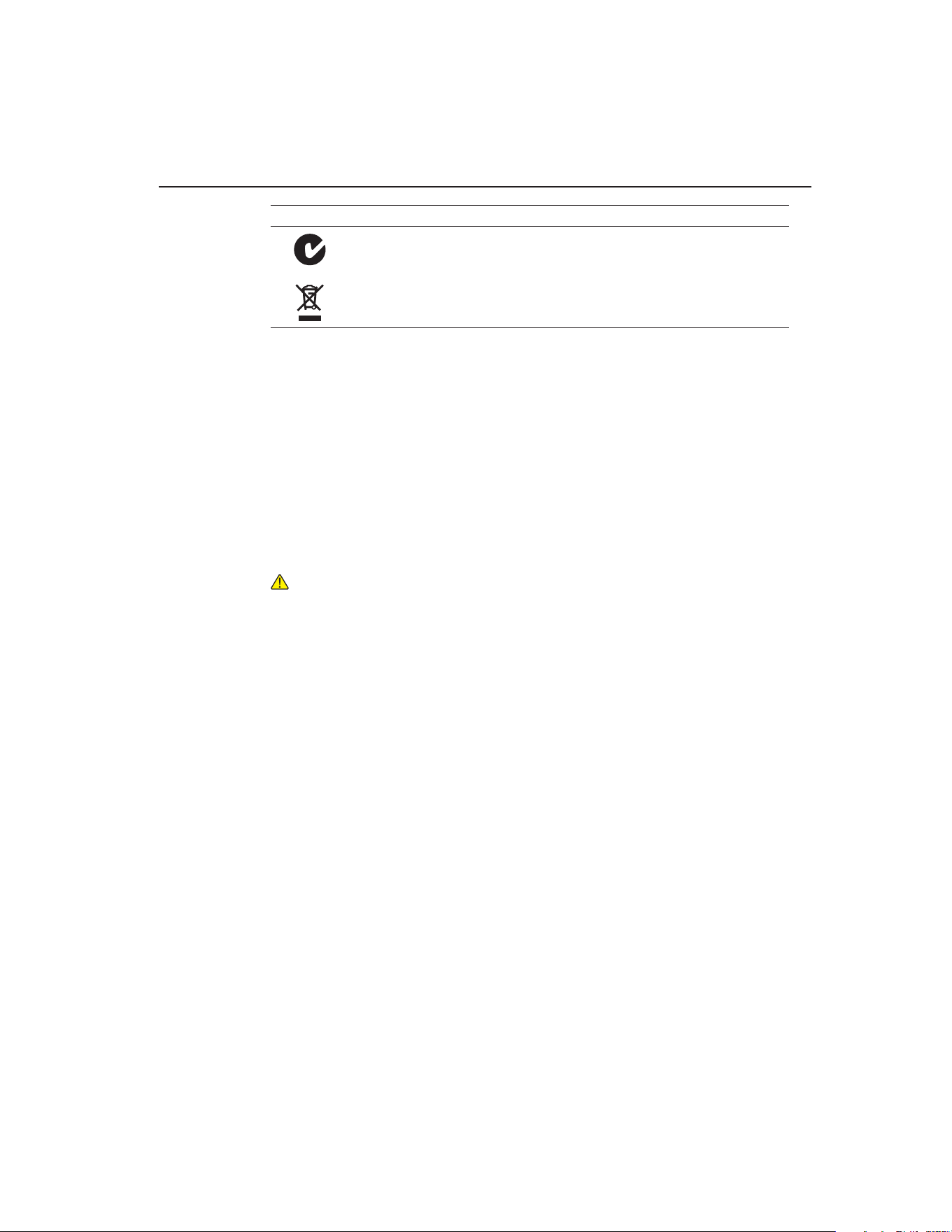
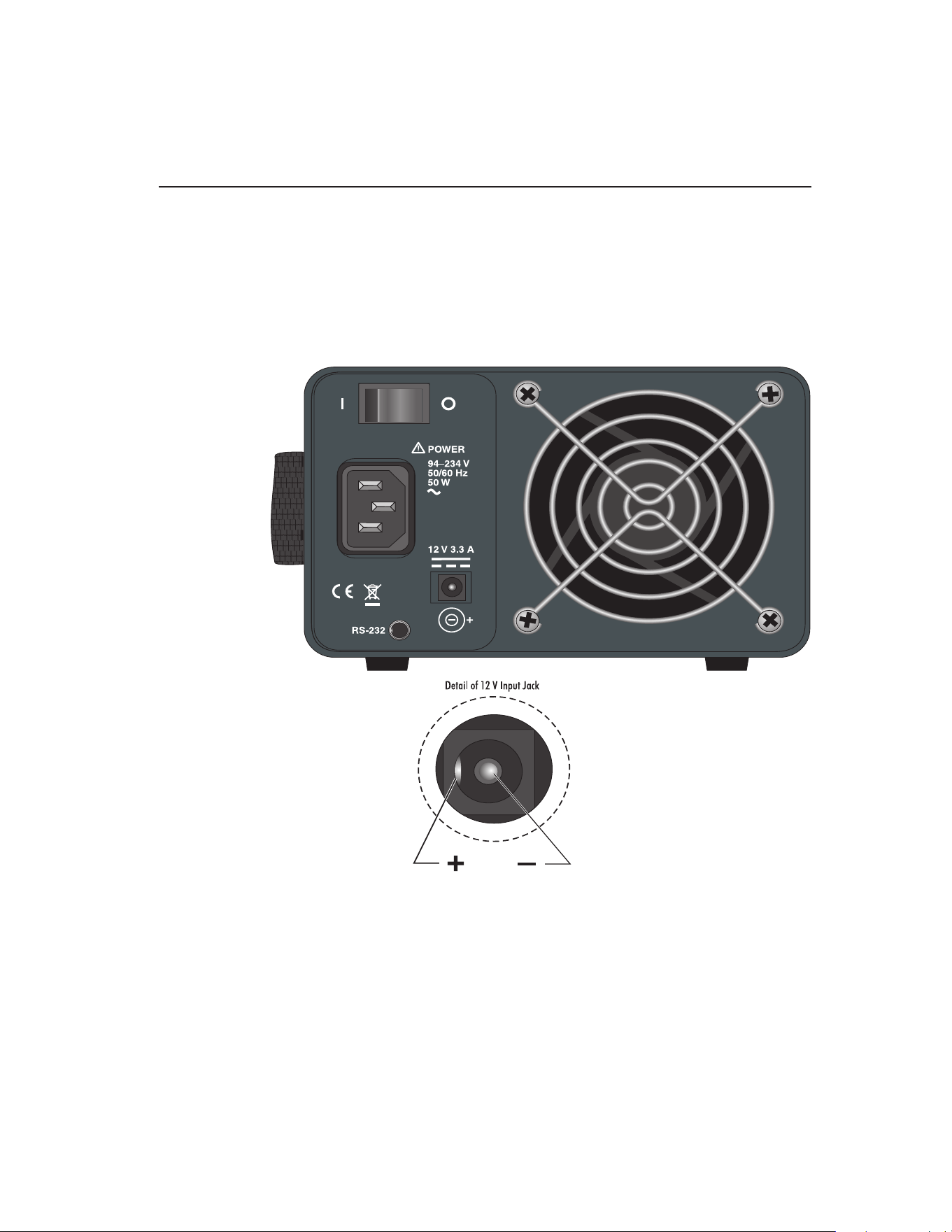
DC Power Operation3.4
This instrument is equipped with a DC power option. The DC option requires a power
source that delivers 12 VDC at 3 amps.
WARNING: A fire may occur if a short circuit occurs along the input cord and
no protective devices are on the DC input source. For short circuit protection
using a battery, a fuse is required at the battery terminals.
The DC power socket is located on the rear panel of the instrument near the AC power
jack. The instrument accepts a 7/32 inch diameter, two-conductor DC power plug
such as Switchcraft® PN. 760. Observe the correct polarity as shown in Figure . The
outside conductor is positive and the inside is negative. The AC power switch on the
rear panel does not switch the DC power.
+
–
Figure 1 12 V DC Power Source Polarity
The optional Model 9320A Battery Pack, available from Fluke, can be used as a por-
table power source.
Setting the Temperature3.5
Section 6.2, Temperature Set-point, on page 19 explains in detail how to set the
temperature set-point on the calibrator using the front panel keys. The procedure is
summarized here.
Press “SET” twice to access the set-point value.1.
Press 2. u or d arrow to change the set-point value.
Press “SET” to program in the new set-point.3.
Press and hold “EXIT” to return to the temperature display.4.
When the set-point temperature is changed the controller switches the well heater
on or off to raise or lower the temperature. The displayed well temperature gradu-
ally changes until it reaches the set-point temperature. The well may require 5 to
10 minutes to reach the set-point depending on the span. Another 5 to 10 minutes is
required to stabilize within ±0.1°C of the set-point. Ultimate stability may take 15 to
20 minutes more of stabilization time.
1.888.610.7664 sales@GlobalTestSupply.com
Fluke-Direct.com
13
Parts and Controls
Rear Panel
Parts and Controls4
The user should become familiar with the dry-well calibrator and its parts: (See Figure
2 on this page and Figure 3 on next page).
Rear Panel4.1
Power Cord - The removable power cord, (Figure ) attaches to the back side of the
instrument. It plugs into a standard 115 VAC (optional 230 VAC) grounded socket.
Figure 2 Back Panel
DC Power Jack - The calibrator can be used with a DC power source. The DC input
jack requires 12V and 3.3 amps. See Figure and the inset of Figure for pinout.
Power Switch - The power switch is located on the back panel of the instrument. The
switch is either on or off. The on position is for normal operation. The off position
disconnects power to the entire unit.
Fan - The instrument utilizes a variable speed fan. Under certain circumstances, the
fan may turn off. The fan shuts off at 100°C and above. Slots at the top and around the
1.888.610.7664 sales@GlobalTestSupply.com
Fluke-Direct.com
9102S Dry-Well Calibrator
Front Panel
14
corners of the instrument are provided for airow. The area around the calibrator must
be kept clear to allow for adequate ventilation. The air is directed from the front to the
back. Allow 6 inches of open space around the calibrator to allow adequate ventilation.
RS-232 - The RS-232 serial port provides a means for connecting the instrument to a
computer or a printer using the included serial cable.
WARNING: Always leave enough clearance in front of the calibrator to allow
for safe and easy installation and removal of probes.
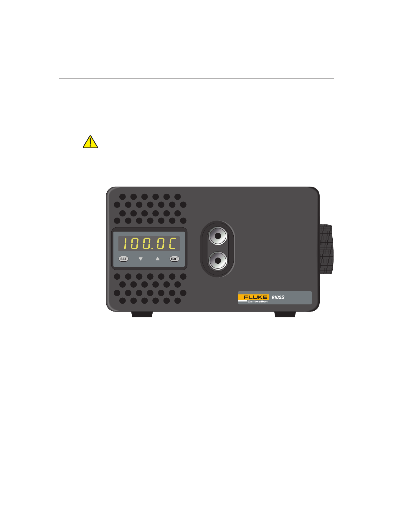
Front Panel4.2
Figure 3 Front Panel
Strap - A strap is provided to aid the user in carrying the instrument in one hand. Slide
your hand into position and secure using the Velcro for a tight t. Be careful when
carrying the instrument while using the strap as inserts can fall out of the wells when
tipped forward. Inspect the strap periodically for wear.
Well Block - Located on the middle of the front panel are the well openings where
probes may be inserted into the well. The block is designed to accept temperature
sensors up to 1/2” (12.7 mm) in diameter. The wells can be made to accept probes
of smaller than 1/2” (12.7 mm) diameter by using optional inserts. Probes should t
snugly into the wells for best results.
Controller Display - The digital display is an important part of the temperature
controller because it not only displays set and actual temperatures but also indicates
various calibrator functions, settings, and constants. The display shows temperatures
in units according to the selected scale °C or °F.
1.888.610.7664 sales@GlobalTestSupply.com
Fluke-Direct.com

15
Parts and Controls
Accessories
Controller Keypad - The four button keypad allows easy setting of the set-point
temperature. The control buttons (SET, d, u, and EXIT) are used to set the calibrator
temperature set-point, access and set other operating parameters, and access and set
calibration parameters.
Setting the control temperature is done directly in degrees of the current scale. It can
be set to one-tenth of a degree Celsius or Fahrenheit.
The functions of the buttons are as follows:
SET – Used to display the next parameter in the menu and to store parameters to the
displayed value.
d (down arrow) – Used to decrement the displayed value of parameters.
u (up arrow) – Used to increment the displayed value.
EXIT – Used to exit a function and to skip to the next function. Any changes made to
the displayed value are ignored.
Accessories4.3
The table below lists optional inserts, carrying case, and battery packs by model
number.
AccessoriesTable 3
Model Description
3102-0 Blank Insert
3102-1 1/16 (1.6 mm) Insert
3102-2 1/8 (3.2 mm) Insert
3102-8 5/32 (4.0 mm) Insert
3102-3 3/16 (4.8 mm) Insert
3102-4 1/4 (6.4 mm) Insert
3102-5 5/16 (7.9 mm) Insert
3102-6 3/8 (9.5 mm) Insert
3102-7 7/16 (11.1 mm) Insert
9308 Rugged Carrying Case
9320A Battery Pack
Call your local Fluke representative for current pricing.
1.888.610.7664 sales@GlobalTestSupply.com
Fluke-Direct.com

1.888.610.7664 sales@GlobalTestSupply.com
Fluke-Direct.com

17
General Operation
Changing Display Units
General Operation5
Setting the Temperature5.1
Section 6.2, Temperature Set-point, on page 19 explains in detail how to set the
temperature set-point on the calibrator using the front panel keys. The procedure is
summarized here.
Press “SET” twice to access the set-point value.1.
Press 2. u or d to change the set-point value.
Press “SET” to program in the new set-point.3.
Press and hold “EXIT” to return to the temperature display.4.
When the set-point temperature is changed the controller switches the well heater on
or off to raise or lower the temperature. The displayed well temperature gradually
changes until it reaches the set-point temperature. The well may require 5 to 10 min-
utes to reach the set-point depending on the span. Another 5 to 10 minutes is required
to stabilize within ±0.05°C of the set-point. Ultimate stability may take 15 to 20 min-
utes more of stabilization time.
Changing Display Units5.2
This instrument can display temperature in Celsius or Fahrenheit. The temperature
units are shipped from the factory set to Celsius. There are two ways to change to
Fahrenheit or back to Celsius.
1 - Press the “SET” and u simultaneously. The temperature display changes units.
or
1 - Press the “SET” key three times from the temperature display to show
Un= C
2 - Press the u or d key to change units.
3 - Press “SET” to save the setting or “EXIT” to continue without changing the
setting.
1.888.610.7664 sales@GlobalTestSupply.com
Fluke-Direct.com

1.888.610.7664 sales@GlobalTestSupply.com
Fluke-Direct.com

19
Controller Operation
Temperature Set-point
Controller Operation6
This chapter discusses in detail how to operate the dry-well temperature controller
using the front control panel. Using the front panel key-switches and LED display the
user may monitor the well temperature, set the temperature set-point in degrees C or F,
monitor the heater output power, adjust the controller proportional band, and program
the calibration parameters, operating parameters, and serial interface conguration.
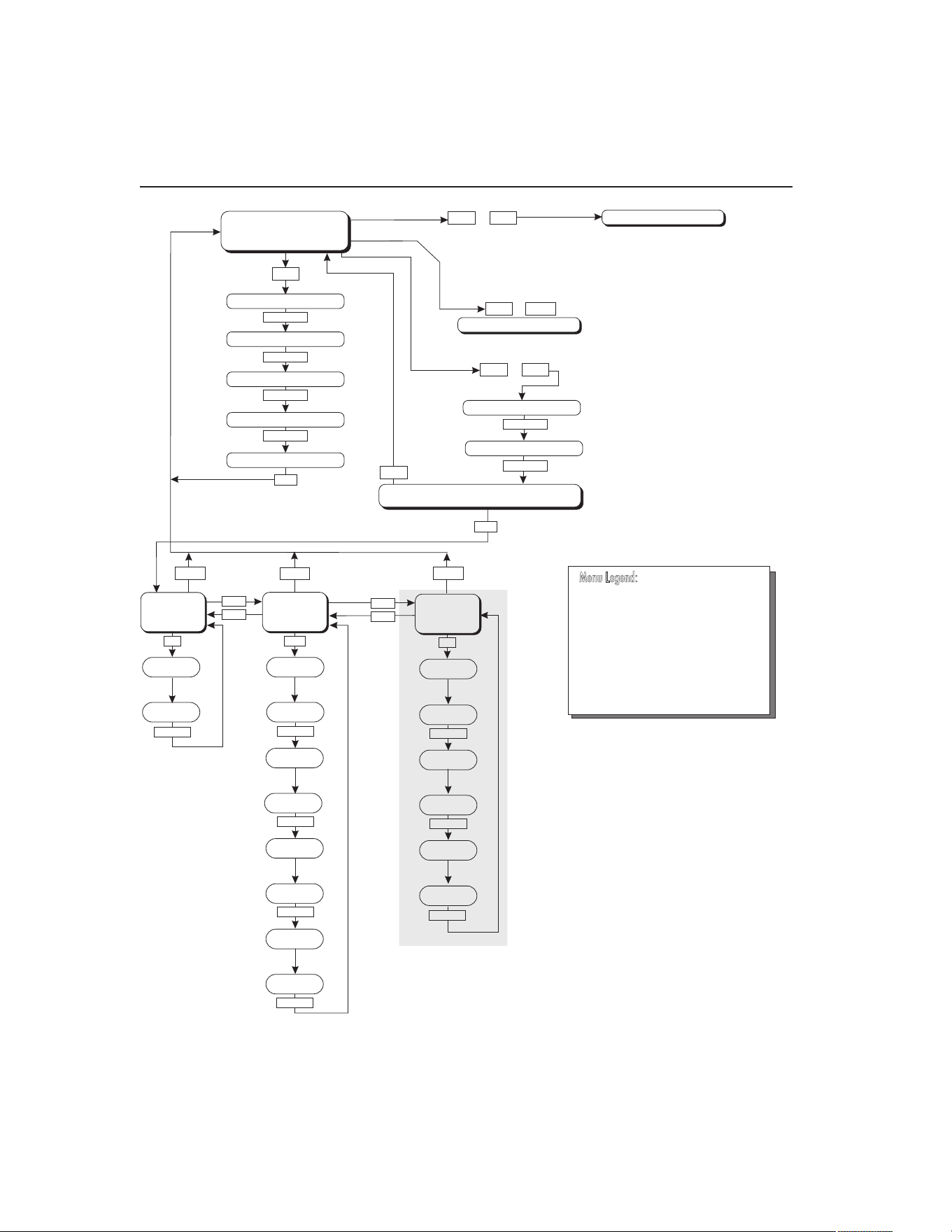
Operation of the functions and parameters are shown in the owchart in Figure 4 on
next page. This chart may be copied for reference.
In the following discussion a button with the word SET or EXIT inside, a u, or d,
indicates the panel button while the dotted box indicates the display reading. Explana-
tions of the button or display reading are to the right of each button or display value.
Well Temperature6.1
The digital LED display on the front panel allows direct viewing of the actual well
temperature. This temperature value is normally shown on the display. The units, C or
F, of the temperature value are displayed at the right. For example,
100.0 C Well temperature in degrees Celsius
The temperature display function may be accessed from any other function by holding
and releasing the “EXIT” button.
6.2 Temperature Set-point
The temperature set-point can be set to any value within the range and with resolution
as given in the specications. Be careful not to exceed the safe upper temperature limit
of any device inserted into the well.
Setting the temperature involves selecting the set-point memory and adjusting the set-
point value.
Programmable Set-points6.2.1
The controller stores 8 set-point temperatures in memory. The set-points can be quick-
ly recalled to conveniently set the calibrator to a previously programmed temperature
set-point.
To set the temperature, rst select the set-point memory. This function is accessed
from the temperature display function by pressing “SET”. The number of the set-point
memory currently being used is shown at the left on the display followed by the cur-
rent set-point value.
100.0 C Well temperature in degrees Celsius
S
Access set-point memory
1 100. Set-point memory 1 location, 100°C currently used
1.888.610.7664 sales@GlobalTestSupply.com
Fluke-Direct.com
9102S Dry-Well Calibrator
Temperature Set-point
20
Figure 4
UP
UP
DOWN
DOWN
SET
Operating
Parameters
Menu
SET
SET
SET/EXIT
SET/EXIT
SET/EXIT
Cal
Menu
SET/EXIT
SET/EXIT
Serial
Interface
Menu
BAUD
Rate
Adjust
BAUD Rate
Sample
Period
Adj. Sample
Period
Duplex
Mode
Adj. Duplex
Mode
Linefeed
Adjust
Linefeed
Select ALPHA
Adjust ALPHA
Select DELTA
Adjust DELTA
EXIT
EXIT
EXIT
EXIT
DOWN
SET
SET
SET
+
+
+
Display Power
Set-Point Resistance
SET
SET/EXIT
SET
SET
Select Setpoint
Adjust Setpoint
Units °C/°F
Scan On/Off
Scan Rate
Display
Temperature
Configuration Menu
Secondary Functions
x5
HL
Adj. HL
SET/EXIT
Units °C/°F
Set Proportional Band
Select R0
Adjust R0
u
EXIT
DO NOT CHANGE THESE VALUES
SET/EXIT
SET/EXIT
SET
Cal
Menu
SET/EXIT
Select ALPHA
Adjust ALPHA
Select DELTA
Adjust DELTA
x5
Select R0
Adjust R0
DO NOT CHANGE THESE VALUES
SET/EXIT
SET/EXIT
Press “SET” to step through the menu and
to store the parameter value.
Press “EXIT” briefly to skipaparameter
without storing the parameter value.
Hold “EXIT” (2seconds) to exit the menu
and display the temperature
»
Menu Legend:
SET/EXIT
SET/EXIT
SET/EXIT
SET/EXIT
SET/EXIT
Controller operation flowchart
1.888.610.7664 sales@GlobalTestSupply.com
Fluke-Direct.com

21
Controller Operation
Temperature Set-point
To change to another set-point memory press the up or down arrow.
4 50. New set-point memory 4 location, 50°C
Press “SET” to accept the new selection and access the set-point value. Press “EXIT”
to continue and to ignore any changes.
S
Accept selected set-point memory
Set-point Value6.2.2
The set-point value may be adjusted after selecting the set-point memory and pressing
“SET”.
4 50. Set-point 4 value in°C
If the set-point value does not need to be changed, press and hold “EXIT” to resume
displaying the well temperature. To change the set-point value, press “SET” and then
press the up or down arrow.
60. New set-point value
When the desired set-point value is reached, press “SET” to accept the new value and
access the temperature scale units selection. If “EXIT” is pressed, any changes made
to the set-point are ignored.
S
Accept new set-point value
Temperature Scale Units6.2.3
The temperature scale units of the controller maybe set by the user to degrees Celsius
(°C) or Fahrenheit (°F). The units are used in displaying the well temperature, set-
point, proportional band, and high limit.
Press “SET” after adjusting the set-point value to change display units.
Un= C Scale units currently selected
Press the up or down arrow to change the units.
Un= F New units selected
Press “SET” to accept the new units or “EXIT” to cancel.
Note: The temperature scale units may also be changed by pressing “SET” and u
when the temperature is displayed.
1.888.610.7664 sales@GlobalTestSupply.com
Fluke-Direct.com

9102S Dry-Well Calibrator
Scan
22
Scan6.3
The scan rate can be set and enabled so that when the set-point is changed the dry-well
heats or cools at a specied rate (degrees per minute) until it reaches the new set-point.
With the scan disabled the dry-well heats or cools at the maximum possible rate.
Scan Control6.3.1
The scan is controlled with the scan on/off function that appears in the main menu
after the temperature scale units.
Sc Scashesforonesecondandthenthecurrentscansetting
is displayed
Off Scanfunctionoff
Press the up or down arrow to toggle the scan on or off.
On Scanfunctionon
Press “SET” to accept the present setting and continue. Press “EXIT” to cancel.
S
Accept scan setting
Scan Rate6.3.2
The scan rate can be set from 0.1 to 99.9°C/min. The maximum scan rate, however,
is actually limited by the natural heating or cooling rate of the instrument. This rate is
often less than 100°C/min, especially when cooling.
The scan rate function appears in the main menu after the scan control function. The
scan rate units are in degrees Celsius per minute, regardless of the selected units.
Sr Srashesforonesecondandthenthecurrentscanrate
setting is displayed
0.1 Scan rate in°C/min
Press the up or down arrow to change the scan rate.
2.0 New scan rate
Press “SET” to accept the new scan rate and continue. Press “EXIT” to cancel.
S
Accept scan rate
Set-point Resistance6.4
The set-point resistance is the resistance the instrument is trying to make the control
sensor achieve and is calculated in the rmware using the set-point temperature. This
value is not directly adjustable but is recalculated when the set-point temperature is
1.888.610.7664 sales@GlobalTestSupply.com
Fluke-Direct.com

23
Controller Operation
Heater Power
changed. The set-point resistance is used to perform a calibration adjustment using
the Callendar-Van Dusen R versus T curve t (see Section , Calibration Procedure).
The instrument must be at temperature and stable prior to taking the set-point resis-
tance reading. The set-point resistance can be displayed by pressing the “SET” and d
simultaneously. The set-point resistance is displayed as follows.
SrES SrESashesfortwosecondsandthenthewholenumber
ofthecurrentset-pointresistancesettingisdisplayed
99. Wholenumberportionoftheset-pointresistanceashes
fortwosecondsandthenthefractionportionofthecurrent
set-point resistance setting is displayed
.222 Fractionportionofthecurrentset-pointresistancesetting
The set-point resistance is 99.222.
Secondary Menu6.5
Functions which are used less often are accessed within the secondary menu. The
secondary menu is accessed by pressing “SET” and “EXIT” simultaneously and then
releasing. The rst function in the secondary menu is the heater power display. (See
Figure .)
Heater Power6.6
The temperature controller controls the temperature of the well by pulsing the heater
on and off. The total power being applied to the heater is determined by the duty
cycle or the ratio of heater on time to the pulse cycle time. By knowing the amount of
heating, the user can tell if the calibrator is heating up to the set-point, cooling down,
or controlling at a constant temperature. Monitoring the percent heater power, allows
the user to know the stability of the well temperature. With good control stability the
percent heating power should not uctuate more than ±5% within one minute.
The heater power display is accessed in the secondary menu. Press “SET” and “EXIT”
simultaneously and release. The heater power is displayed as a percentage of full
power.
100.0 C Well temperature
S+E
Accessheaterpowerinsecondarymenu
SEC FlashesSECforsecondarymenuandthendisplaysthe
heaterpower
12.0P Heater power in percent
To exit out of the secondary menu press “EXIT”. To continue on to the proportional
band setting function press “SET”.
1.888.610.7664 sales@GlobalTestSupply.com
Fluke-Direct.com

9102S Dry-Well Calibrator
Proportional Band
24
Proportional Band6.7
In a proportional controller such as this, the heater output power is proportional to the
well temperature over a limited range of temperatures around the set-point. This range
of temperature is called the proportional band. At the bottom of the proportional band,
the heater output is 100%. At the top of the proportional band, the heater output is 0.
Thus, as the temperature rises the heater power is reduced, which consequently tends
to lower the temperature back down. In this way the temperature is maintained at a
constant level.
The temperature stability of the well and response time depend on the width of the
proportional band. If the band is too wide, the well temperature deviates excessively
from the set-point due to varying external conditions. This is because the power output
changes very little with temperature and the controller cannot respond very well to
changing conditions or noise in the system. If the proportional band is too narrow, the
temperature may swing back and forth because the controller overreacts to tempera-
ture variations. For best control stability, the proportional band must be set for the
optimum width.
The proportional band width is set at the factory as printed on the Report of Calibra-
tion. The proportional band width may be altered by the user if desired to optimize the
control characteristics for a particular application.
The proportional band width is easily adjusted from the front panel. The width may
be set to discrete values in degrees C or F depending on the selected units. The pro-
portional band adjustment is accessed within the secondary menu. Press “SET” and
“EXIT” to enter the secondary menu and show the heater power. Then press “SET” to
access the proportional band.
S+E
Accessheaterpowerinsecondarymenu
SEC FlashesSECforsecondarymenuandthendisplaysthe
heaterpower
12.0P Heater power in percent
S
Accessproportionalband
PrOP Flashespropandthendisplaysthesetting
4.1 Proportionalbandsetting
To change the proportional band press u or d.
10.0 Newproportionalbandsetting
To accept the new setting press “SET”. Press “EXIT” to continue without storing the
new value.
S
Acceptthenewproportionalbandsetting
1.888.610.7664 sales@GlobalTestSupply.com
Fluke-Direct.com

25
Controller Operation
Serial Interface Parameters
Controller Conguration6.8
The controller has a number of conguration and operating options and calibration
parameters which are programmable via the front panel. These are accessed from the
secondary menu after the proportional band function by pressing “SET”. Pressing
“SET” again enters the rst of three sets of conguration parameters — operating
parameters, serial interface parameters, and calibration parameters. The menus are
selected using the up and down arrows and then pressing “SET”.
6.9 Operating Parameters
The operating parameters menu is indicated by,
PAr Operating parameters menu
The operating parameters menu contains the High Limit parameter.
High Limit6.10
The High Limit parameter adjusts the upper set-point temperature. The factory default
and maximum are set to 125°C (257°F). The minimum setting is 50°C (122°F). For
safety, a user can adjust the High Limit down so the maximum temperature set-point is
restricted.
HL FlashesHLandthendisplaysthesetting
125 Flashesthecurrentvalueandthendisplaysthevaluefor
adjustment
125 CurrentHighLimitsetting
Press the u or d to adjust the setting.
100 NewHighLimitsetting
To accept the new setting, press “SET”. Press “EXIT” to continue without storing the
new value.
S
AcceptthenewHighLimitsetting
Serial Interface Parameters6.11
The serial RS-232 interface parameters menu is indicated by,
SErL SerialRS-232interfaceparametersmenu
Press “SET” to enter the menu. The serial interface parameters menu contains param-
eters which determine the operation of the serial interface. The parameters in the menu
are — baud rate, sample period, duplex mode, and linefeed.
1.888.610.7664 sales@GlobalTestSupply.com
Fluke-Direct.com

9102S Dry-Well Calibrator
Serial Interface Parameters
26
Baud Rate6.11.1
The baud rate is the rst parameter in the menu. The baud rate setting determines the
serial communications transmission rate.
The baud rate parameter is indicated by,
bAUd FlashesbAUdforonesecondandthendisplaysthesetting
2400b Currentbaudrate
The BAUD rate of the serial communications may be programmed to 300, 600, 1200,
2400 (default), 4800, or 9600 BAUD. Use the up or down arrows to change the BAUD
rate value.
4800 b Newbaudrate
Press “SET” to accept the new setting or “EXIT” to abort the operation and skip to the
next parameter in the menu.
Sample Period6.11.2
The sample period is the next parameter in the serial interface parameter menu. The
sample period is the time period in seconds between temperature measurements trans-
mitted from the serial interface. If the sample rate is set to 5, the instrument transmits
the current measurement over the serial interface approximately every ve seconds.
The automatic sampling is disabled with a sample period of 0. The sample period is
indicated by,
SPEr Flashesforonesecondandthentheserialsampleperiod
setting is displayed
1 Current sample period (seconds)
Adjust the value by using the up or down arrows (u d).
60 New sample period
Press “SET” to accept the new setting or “EXIT” to abort the operation and skip to the
next parameter in the menu.
Duplex Mode6.11.3
The next parameter is the duplex mode. The duplex mode may be set to full duplex or
half duplex. With full duplex any commands received by the calibrator via the serial
interface are immediately echoed or transmitted back to the device of origin. With half
duplex the commands are executed but not echoed. The duplex mode parameter is
indicated by,
dUPL Flashesforonesecondandthentheserialduplexmode
setting is displayed
1.888.610.7664 sales@GlobalTestSupply.com
Fluke-Direct.com
27
Controller Operation
Calibration Parameters
FULL Currentduplexmodesetting
The mode may be changed using the up or down arrows (u d).
HALF Newduplexmodesetting
Press “SET” to accept the new setting or “EXIT” to abort the operation and skip to the
next parameter in the menu.
Linefeed6.11.4
The nal parameter in the serial interface menu is the linefeed mode. This parameter
enables (on) or disables (off) transmission of a linefeed character (LF, ASCII 10) after
transmission of any carriage-return. The linefeed parameter is indicated by,
LF Flashesforonesecondandthentheseriallinefeedsetting
is displayed
On Currentlinefeedsetting
The mode may be changed using the up or down arrows (u d).
OFF Newlinefeedsetting
Press “SET” to accept the new setting or “EXIT” to abort the operation and skip to the
next parameter in the menu.
6.12 Calibration Parameters
The operator of the instrument controller has access to a number of the calibration
constants: R0, ALPHA, and DELTA. These values are set at the factory and must
not be altered. The correct values are important to the accuracy and proper and safe
operation of the instrument. Access to these parameters is available to the user so that
in the event that the controller memory fails the user may restore these values to the
factory settings. The user should have a list of these constants and their settings with
the instrument manual.
CAUTION: DO NOT change the values of the instrument calibration constants
from the factory set values. The correct setting of these parameters is important
to the safety, proper operation, and performance of the instrument.
The calibration parameters menu is indicated by,
CAL Calibrationparametersmenu
Press “SET” ve times to enter the menu. The calibration parameters menu con-
tains the parameters, Hard Cutout, R0, ALPHA, and DELTA, which characterize the
resistance-temperature relationship of the platinum control sensor. These parameters
may be adjusted to improve the accuracy of the calibrator.
1.888.610.7664 sales@GlobalTestSupply.com
Fluke-Direct.com

The calibration parameters are accessed by pressing “SET” after the name of the pa-
rameter is displayed. The value of the parameter may be changed using the up or down
arrow. After the desired value is reached, press “SET” to set the parameter to the new
value. Pressing “EXIT” causes the parameter to be skipped ignoring any changes that
may have been made.
R06.12.1
This probe parameter refers to the resistance of the control probe at 0°C. The value of
this parameter is set at the factory for best instrument accuracy. The value ranges from
95 to 105. For values greater than 100.000, the display does not show the hundreds
placement. For values less than 100.000, the display shows the entire value. The R0
parameter is indicated by,
r0 FlashesforonesecondandthentheR0settingisdisplayed
00.014 Current R0 setting (100.014)
To change the R0 setting, press the up or down arrows.
99.999 New R0 setting
To accept the new setting, press “SET”. Press “EXIT” to continue without storing the
new value.
S
AcceptthenewR0setting
ALPHA6.12.2
This probe parameter refers to the average sensitivity of the probe between 0 and
100°C. The value of this parameter is set at the factory for best instrument accuracy.
aLpha FlashesforonesecondandthentheALPHAsettingis
displayed
38530 CurrentALPHAsetting
To change the ALPHA setting, press the up or down arrows.
38600 NewALPHAsetting
To accept the new setting, press “SET”. Press “EXIT” to continue without storing the
new value.
S
AcceptthenewALPHAsetting
1.888.610.7664 sales@GlobalTestSupply.com
Fluke-Direct.com

DELTA6.12.3
This probe parameter characterizes the curvature of the resistance-temperature rela-
tionship of the sensor. The value of this parameter is set at the factory for best instru-
ment accuracy.
DeLta FlashesforonesecondandthentheDELTAsettingis
displayed
0.0000 CurrentDELTAsetting
To change the DELTA setting, press the up or down arrows.
0.1000 NewDELTAsetting
To accept the new setting, press “SET”. Press “EXIT” to continue without storing the
new value.
S
AcceptthenewDELTAsetting
1.888.610.7664 sales@GlobalTestSupply.com
Fluke-Direct.com

1.888.610.7664 sales@GlobalTestSupply.com
Fluke-Direct.com
31
Digital Communication Interface
RS-232 Connection
Digital Communication Interface7
This instrument is capable of communicating with and being controlled by other
equipment through the digital serial interface.
With a digital interface, the instrument may be connected to a computer or other
equipment. This allows the user to set the set-point temperature, monitor the tempera-
ture, and access any of the other controller functions, all using remote communications
equipment. Communications commands are summarized in Table 4 on next page.
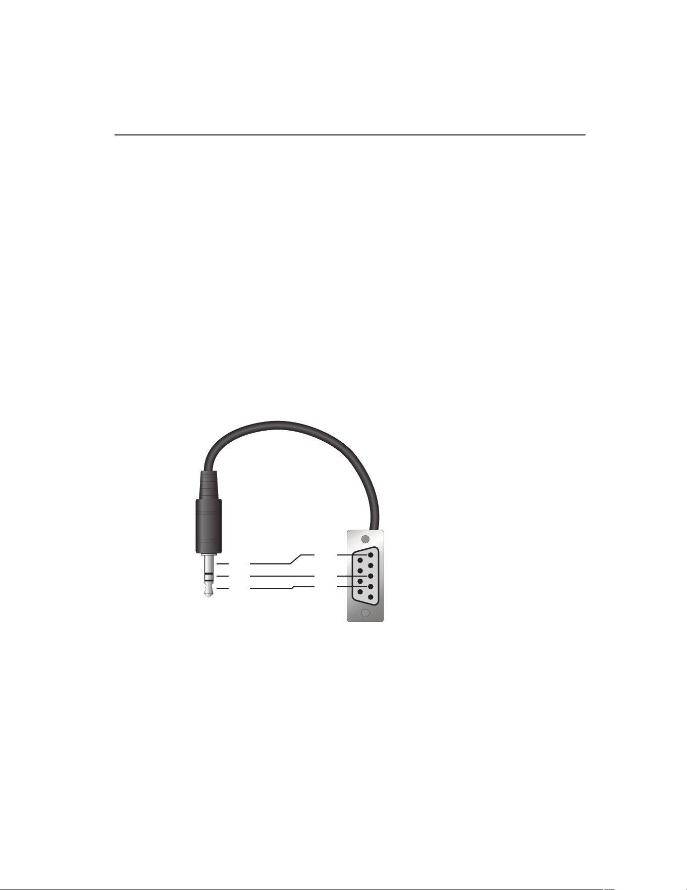
RS-232 Connection7.1
The three-conductor jack for the serial port is located on the back of the instrument.
One serial cable is included. Additional or longer cables, of three meters or less, can
be constructed by following the wiring diagram shown in Figure 5 on this page. Note:
The TxD line on one side connects to the RxD line on the other and vice-versa. To
reduce the possibility of electrical interference, the serial cable should be shielded with
low resistance between the connector and the shield and should not be much longer
than is necessary. The protocol for serial communications is 8 data bits, 1 stop bit, and
no parity. Use no ow control. Set the linefeed to ON (all carriage returns are followed
by a linefeed (LF, ASCII 10)), and the duplex to HALF, disabling echo.
Figure 5
1
2
3
4
5
6
7
8
9
RxD
TxD
GND
RxD
TxD
GND
Serial Cable Wiring
The serial port can be used to transmit measurements to a computer or printer or to
change settings of the instrument from a computer. A full list of commands follows in
Section 7.2, Interface Commands, on page 32.
Commands sent to the instrument must end with an EOS character which is a carriage
return (CR, ASCII 13) or linefeed character (LF, ASCII 10). Commands can be sent
with upper or lower case letters. Data returned from the instrument end with a carriage
return. If the linefeed setting is on, a linefeed is also sent after the carriage return.
1.888.610.7664 sales@GlobalTestSupply.com
Fluke-Direct.com

9102S Dry-Well Calibrator
Interface Commands
32
7.2 Interface Commands
The various commands for accessing the calibrator functions via the digital interface
are listed in this section (see Table 4 on this page). These commands are used with the
RS-232 serial interface. The commands are terminated with a carriage-return character
(CR, ASCII 13). The interface makes no distinction between upper and lower case
letters, hence either may be used. Commands may be abbreviated to the minimum
number of letters which determines a unique command. A command may be used to
either set a parameter or display a parameter depending on whether or not a value is
sent with the command following a “=” character. For example “s” returns the current
set-point and “s=120.0” sets the set-point to 120.0 degrees.
In the following list of commands, characters or data within brackets, “[” and “]”, are
optional for the command. A slash, “/”, denotes alternate characters or data. Numeric
data, denoted by “n”, may be entered in decimal or exponential notation. Characters
are shown in lower case although upper case may be used. Spaces may be added
within command strings and will simply be ignored. Backspace (BS, ASCII 8) may be
used to erase the previous character. A terminating carriage return (CR, ASCII 13) is
implied with all commands.
Table 4 Controller communications commands
Command Description
Command
Format
Command
Example
Returned
Returned
Example
Acceptable
Values
Display Temperature
Read current set-point s[etpoint] s set: 999.99 {C
or F}
set: 75.00 C
Set current set-point to n s[etpoint]=n
t[emperature]=n
s=100
t=100
–10 to 122°C
14 to 252°F
Read temperature t[emperature] t t: 999.9 {C or F} t: 55.6 C
Read temperature units u[nits] u u: x u: C
Set temperature units: u[nits]=c/f C or F
Set temperature units to Celsius u[nits]=c u=c
Set temperature units to
Fahrenheit
u[nits]=f u=f
Read scan mode sc[an] sc sc: {ON or OFF} sc: ON
Set scan mode sc[an]=on/off sc=on ON or OFF
Read scan rate sr[ate] sr srat: 99.9 {C or
F}/min
srat:12.4 C/min
Set scan rate sr[ate]=n sr=1.1 0.1 to 99.9°C
0.2 to 179.8°F
Secondary Menu
Read proportional band setting pr[op-band] pr pb: 999.99999 pb: 15.9
Set proportional band to n pr[op-band]=n pr=8.83 0.1 to 30°C
0.2 to 54°F
Read heater power (duty cycle) po[wer] po po: 999.9 po: 6.5
Conguration Menu
Operating Parameters Menu
Read High Limit hl[imit] hl hl: 9999 hl: 125
Set High Limit hl[imit]=n hl=100 50 to 125°C
122 to 257°F
1.888.610.7664 sales@GlobalTestSupply.com
Fluke-Direct.com
33
Digital Communication Interface
Interface Commands
Command Description
Command
Format
Command
Example
Returned
Returned
Example
Acceptable
Values
Serial Interface Menu
Read serial sample setting sa[mple] sa sa: 99999 sa: 1
Set serial sampling setting to n seconds sa[mple]=n sa=0 0 to 10,000
Set serial duplex mode: du[plex]=f[ull]/
h[alf]
FULL or HALF
Set serial duplex mode to full du[plex]=f[ull] du=f
Set serial duplex mode to half du[plex]=h[alf] du=h
Set serial linefeed mode: lf[eed]=on/of[f] ON or OFF
Set serial linefeed mode to on lf[eed]=on lf=on
Set serial linefeed mode to off lf[eed]=of[f] lf=of
Calibration Menu
Read R0 calibration parameter r[0] r r0: 999.999 r0: 100.7
Set R0 calibration parameter to n r[0]=n r=100.7 95.0 to 105.0
Read ALPHA calibration parameter al[pha] al al: 9.99999999 al: 0.003865
Set ALPHA calibration parameter to n al[pha]=n al=0.003865 0.002 to 0.006
Read DELTA calibration parameter de[lta] de de: 1.50
Set DELTA calibration parameter de[lta]=n de=1.37 de: 9.99999 0.0–3.0
Miscellaneous Other Commands
Read rmware version number *ver[sion] *ver ver.9999x,9.99 ver.9102S,1.10
Read structure of all commands h[elp] h list of
commands
Read ALL operating parameters all all list of
parameters
Read set-point *sr *sr 999.999 ohms 100.123 ohms
Legend: [] Optional command data
{} Returns either information
n Numeric data supplied by user
9 Numeric data returned to user
x Character data returned to user
Note: When DUPLEX is set to FULL and a command is sent to READ, the command is returned
followed by a carriage return and linefeed. Then the value is returned as indicated in the
RETURNED column.
1.888.610.7664 sales@GlobalTestSupply.com
Fluke-Direct.com

1.888.610.7664 sales@GlobalTestSupply.com
Fluke-Direct.com

35
Test Probe Calibration
Dry-well Characteristics
Test Probe Calibration8
For optimum accuracy and stability, allow the calibrator to warm up for 10 minutes
after power-up and then allow adequate stabilization time after reaching the set-point
temperature. After completing operation of the calibrator, allow the well to cool by set-
ting the temperature to 25°C for one-half hour before switching the power off.
Calibrating a Single Probe8.1
Insert the probe to be calibrated into the well of the instrument. The probe should
t snugly into the calibrator probe sleeve yet should not be so tight that it cannot be
easily removed. Avoid any dirt or grit that may cause the probe to jam into the sleeve.
Best results are obtained with the probe inserted to the full depth of the well. Once the
probe is inserted into the well, allow adequate stabilization time to allow the test probe
temperature to settle as described above. Once the probe has settled to the temperature
of the well, it may be compared to the calibrator display temperature. The display
temperature should be stable to within ±0.05°C degree for best results.
CAUTION: Never allow foreign material into the wells of the block. Fluids and
other materials can damage the instrument causing binding and damage to your
probe.
Dry-well Characteristics8.2
There is a temperature gradient vertically in the test well. The heater has been applied
to the block in such a way as to compensate for nominal heat losses out of the top of
the dry-well. However, actual heat losses vary with design of the thermometer probes
inserted into the calibrator and the temperature. For best results, insert probe to full
depth of well.
Stabilization and Accuracy 8.2.1
The stabilization time of the instrument depends on the conditions and temperatures
involved. Typically, the test well stabilizes to ±0.05°C within 7 minutes of reaching
the set-point temperature as indicated by the display. Ultimate stability is achieved 10
to 20 minutes after reaching the set temperature.
Depending on the magnitude of the disturbance and the required accuracy, inserting
a cold probe into a warm well will require another stabilization period. For example,
inserting a 0.25 inch diameter room temperature probe into a sleeve at 120°C takes 7
minutes to be within ±0.05°C of its settled point and might take 15 minutes to achieve
maximum stability.
Speeding up the calibration process can be accomplished by knowing how soon to
make the measurement. It is recommended that typical measurements be made at the
desired temperatures with the desired test probes to establish these times.
1.888.610.7664 sales@GlobalTestSupply.com
Fluke-Direct.com

1.888.610.7664 sales@GlobalTestSupply.com
Fluke-Direct.com

37
Calibration Procedure
Calibration Procedure
Calibration Procedure9
Note: This procedure is to be considered a general guideline. Each laboratory
should write their own procedure based on their equipment and their quality
program. Each procedure should be accompanied by an uncertainty analysis
also based on the laboratory’s equipment and environment.
Sometimes the user may want to calibrate the dry-well to improve the temperature
set-point accuracy. Calibration is done by adjusting the controller probe calibra-
tion constants R0 , ALPHA, and DELTA so that the temperature of the dry-well as
measured with a standard thermometer agrees more closely with the set-point. The
thermometer used must be able to measure the well temperature with higher accuracy
than the desired accuracy of the dry-well. By using a good thermometer and following
this procedure the dry-well can be calibrated to an accuracy of better than 0.25°C over
its full range.
Calibration Points9.1
In calibrating the dry-well, R0, ALPHA, and DELTA are adjusted to minimize the
set-point error at each of three different dry-well temperatures. Any three reasonably
separated temperatures may be used for the calibration. Improved results can be ob-
tained for shorter ranges when using temperatures that are just within the most useful
operating range of the dry-well. The farther apart the calibration temperatures, the
greater the calibrated temperature range. However, the calibration error is also greater
over the range. For instance, if 10°C to 100°C is chosen as the calibration range, the
calibrator may achieve an accuracy of ±0.25°C over the range 10°C to 100°C. Choos-
ing a range of 50°C to 100°C may allow the calibrator to have a better accuracy of
maybe ±0.2°C over the range 75°C to 105°C but outside that range the accuracy may
be only ±0.25°C.
Calibration Procedure9.2
Choose three set-points to use in the calibration of the R0, ALPHA, and DELTA 1.
parameters. These set points are generally 2°C, 50°C, and 100°C but other set
points may be used if desired or necessary.
Set the dry-well to the lowest set-point. When the dry-well reaches the set-point 2.
and the display is stable, wait 15 minutes or so and then take a reading from
the thermometer. Sample the set-point resistance by holding down “SET” and
pressing the d. Write these values down as T
1
and R
1
respectively.
Repeat step 2 for the other two set-points recording them as T3.
2
and R
2
and T
3
and R
3
respectively.
Using the recorded data, calculate new values for the R0, ALPHA, and DELTA.4.
Compute DELTA9.2.1
AT T=−
32
1.888.610.7664 sales@GlobalTestSupply.com
Fluke-Direct.com

9102S Dry-Well Calibrator
Calibration Procedure
38
BT T=−
21
C
TT
TT
=
−
−
−
33
22
100
1
100 100
1
100
D
TTTT
=
−
−
−
2211
100
1
100 100
1
100
ERT=−
32
FRT=−
21
delta
AF BE
DE CF
=
−
−
T
1-3
- Measured temperature using thermometer.
R
1-3
- Value of set-point resistance from the instrument display. (Press “SET” and d at
the same time.)
where
T
1
and R
1
are the measured temperature and set-point resistance at 2.0 °C
T
2
and R
2
are the measured temperature and set-point resistance at 50.0 °C
T
3
and R
3
are the measured temperature and set-point resistance at 100.0 °C
Compute R0 and ALPHA9.2.2
aTdelta
TT
11
11
100
1
100
=+
−
aTdelta
TT
33
33
100
1
100
=+
−
rzero
Ra Ra
aa
=
−
−
31 13
13
alpha
RR
Ra Ra
=
−
−
13
31 13
delta is the new value of DELTA computed above
Program the new values for DELTA (delta), R0 (rzero), and ALPHA (alpha) into the
dry-well using the following steps.
1.888.610.7664 sales@GlobalTestSupply.com
Fluke-Direct.com

39
Calibration Procedure
Calibration Procedure
Press “SET” and “EXIT” at the same time. Press “SET” until 5. PAR is displayed.
and then press u until CAL is displayed.
Press “SET” five times to enter the menu.6.
Press “SET” and 7. u or d until the correct numerical setting is displayed. Press
“SET” to accept the new value.
Repeat step 3. for ALPHA and DELTA.8.
Press “EXIT” to show the displayed temperature.9.
Accuracy and Repeatability9.2.3
Check the accuracy of the dry-well at various points over the calibration range. If dry-
well does not pass specication at all set-points, repeat the Calibration Procedure.
1.888.610.7664 sales@GlobalTestSupply.com
Fluke-Direct.com

1.888.610.7664 sales@GlobalTestSupply.com
Fluke-Direct.com

41
Maintenance
Maintenance10
This instrument has been designed with the utmost care. Ease of operation
●●
and simplicity of maintenance have been a central theme in the product
development. Therefore, with proper care the instrument should require very
little maintenance. Avoid operating the instrument in an oily, wet, dirty, or dusty
environment.
If the outside of the instrument becomes soiled, it may be wiped clean with
●●
a damp cloth and mild detergent. Do not use harsh chemicals on the surface
which may damage the paint.
It is important to keep the well of the calibrator clean and clear of any foreign
●●
matter. Do not use uid to clean out the well.
Use a commercially available plastic or felt brush, of appropriate diameter for
●●
a tight t without any uid, to clean the well. Complete the cleaning process by
using cotton swabs and air to remove any debris.
Inserts should be cleaned periodically. For cold dry-wells operating below 0°C,
●●
you should always clean the inserts after operating the unit at or below 0°C.
Use emery cloth or other similar material to clean the outside of the inserts.
Ensure that the inserts are wiped clean of any debris loosened in the bufng
process. Periodic cleaning of the outside of the inserts ensures easy insertion
and removal of the inserts from the well.
The dry-well calibrator should be handled with care. Avoid knocking or
●●
dropping the calibrator.
Do not drop the probe stems into the well. This type of action can cause a shock
●●
to the sensor.
If a hazardous material is spilt on or inside the equipment, the user is
●●
responsible for taking the appropriate decontamination steps as outlined by the
national safety council with respect to the material.
If the mains supply cord becomes damaged, replace it with a cord with the
●●
appropriate gauge wire for the current of the instrument. If there are any
questions, call an Authorized Service Center (see Section 1.4, Authorized
Service Centers, on page 6) for more information.
Before using any cleaning or decontamination method except those
●●
recommended by Fluke, users should check with an Authorized Service Center
to be sure that the proposed method will not damage the equipment.
If the instrument is used in a manner not in accordance with the equipment
●●
design, the operation of the dry-well may be impaired or safety hazards may
arise.
1.888.610.7664 sales@GlobalTestSupply.com
Fluke-Direct.com

1.888.610.7664 sales@GlobalTestSupply.com
Fluke-Direct.com

43
Troubleshooting
Troubleshooting Problems, Possible Causes, and Solutions
Troubleshooting11
This section contains information on troubleshooting, CE Comments, and a wiring
diagram.
Troubleshooting Problems, Possible Causes, and Solutions11.1
In the event that the instrument appears to function abnormally, this section may help
to nd and solve the problem. Several possible problem conditions are described along
with likely causes and solutions. If a problem arises, please read this section carefully
and attempt to understand and solve the problem. If the problem cannot otherwise be
solved, contact an Authorized Service Center (see Section 1.4, Authorized Service
Centers, on page 6) for assistance. Be sure to have the model number, serial number,
voltage, and problem description available.
Problem Possible Causes and Solutions
Incorrect
temperature reading
Incorrect R0, ALPHA, and DELTA parameters. Find the value for R0, ALPHA,
and DELTA on the Report of Calibration. Reprogram the parameters into the
instrument (see Section , Calibration Parameters). Allow the instrument to
stabilize and verify the accuracy of the temperature reading.
Controller locked up. The controller may have locked up due to a power surge or
other aberration. Initialize the system by performing the Factory Reset Sequence.
Factory Reset Sequence. Hold the SET and EXIT buttons down at the same time
while powering up the instrument. The instrument displays shows ‘-init-‘, the
model number, and the rmware version. Each of the controller parameters and
calibration constants must be reprogrammed. The values can be found on the
Report of Calibration (see Section 6.12, Calibration Parameters, on page 27).
The instrument
heats or cools too
quickly or too slowly
Incorrect scan and scan rate settings. The scan and scan rate settings may be set
to unwanted values. Check the Scan and Scan Rate settings. The scan may be
off (if the unit seems to be responding too quickly). The scan may be on with the
Scan Rate set low (if unit seems to be responding too slowly).
Improper line voltage. Verify that the voltage reading in the bottom of the unit
matches the source voltage.
Unstable display Wait. Allow the instrument to stabilize for a few minutes.
Proportional band may be incorrect. Refer to the proportional band on the Report
of Calibration.
The display shows
an error code
Controller problem. The error messages signify the following problems with the
controller.
Err 1 - a RAM error
Err 2 - a NVRAM error
Err 3 - a Structure error
Err 4 - an ADC setup error
Err 5 - an ADC ready error
Err 6 – a defective control sensor
Err 7 – a heater error
Initialize the system by performing the Factory Reset Sequence describe above.
Temperature cannot
be set above a
certain point
Incorrect High Limit parameter. The High Limit parameter may be set below 125°C.
Check this value as described in Section 6.9, Operating Parameters, on page 25.
Display is reading
incorrectly
The instrument was turned off at high temperatures and reenergized too quickly.
Turn the instrument off until the display is completely off and then reenergize.
Display ickers
when the
instrument is turned
off
This is normal operation and is more prevalent at high temperatures due to
Seebeck Coefficient of the thermoelectric cooling devices. Some time is required
to fully discharge the switching power supply and to complete the power off cycle.
1.888.610.7664 sales@GlobalTestSupply.com
Fluke-Direct.com

9102S Dry-Well Calibrator
CE Comments
44
Problem Possible Causes and Solutions
The instrument
does not reach
temperature
The specications for the instrument include an ambient temperature of 23°C.
If the ambient temperature is above 23°C, the instrument may not be able to
reach the lowest specied temperature. Check the ambient temperature if the
instrument does not reach maximum temperature.
CE Comments11.2
EMC Directive11.2.1
Fluke’s equipment has been tested to meet the European Electromagnetic Compatibil-
ity Directive (EMC Directive, 89/336/EEC). The Declaration of Conformity for your
instrument lists the specic standards to which the unit was tested.
Low Voltage Directive (Safety)11.2.2
In order to comply with the European Low Voltage Directive (73/23/EEC), Fluke
equipment has been designed to meet the IEC 1010-1 (EN 61010-1) and the IEC
1010-2-010 (EN 61010-2-010) standards.
1.888.610.7664 sales@GlobalTestSupply.com
Fluke-Direct.com

®
725
Multifunction Process Calibrator
Users Manual
October, 1998 Rev.3, 5/04
© 1998-2004 Fluke Corporation, All rights reserved.
All product names are trademarks of their respective companies.
1.888.610.7664 sales@GlobalTestSupply.com
Fluke-Direct.com

LIMITED WARRANTY AND LIMITATION OF LIABILITY
Each Fluke product is warranted to be free from defects in material and workmanship under normal use and service. The warranty period is three years and
begins on the date of shipment. Parts, product repairs, and services are warranted for 90 days. This warranty extends only to the original buyer or end-user
customer of a Fluke authorized reseller, and does not apply to fuses, disposable batteries, or to any product which, in Fluke’s opinion, has been misused, altered,
neglected, contaminated, or damaged by accident or abnormal conditions of operation or handling. Fluke warrants that software will operate substantially in
accordance with its functional specifications for 90 days and that it has been properly recorded on non-defective media. Fluke does not warrant that software will
be error free or operate without interruption.
Fluke authorized resellers shall extend this warranty on new and unused products to end-user customers only but have no authority to extend a greater or different
warranty on behalf of Fluke. Warranty support is available only if product is purchased through a Fluke authorized sales outlet or Buyer has paid the applicable
international price. Fluke reserves the right to invoice Buyer for importation costs of repair/replacement parts when product purchased in one country is submitted
for repair in another country.
Fluke’s warranty obligation is limited, at Fluke’s option, to refund of the purchase price, free of charge repair, or replacement of a defective product which is
returned to a Fluke authorized service center within the warranty period.
To obtain warranty service, contact your nearest Fluke authorized service center to obtain return authorization information, then send the product to that service
center, with a description of the difficulty, postage and insurance prepaid (FOB Destination). Fluke assumes no risk for damage in transit. Following warranty
repair, the product will be returned to Buyer, transportation prepaid (FOB Destination). If Fluke determines that failure was caused by neglect, misuse,
contamination, alteration, accident, or abnormal condition of operation or handling, including overvoltage failures caused by use outside the product’s specified
rating, or normal wear and tear of mechanical components, Fluke will provide an estimate of repair costs and obtain authorization before commencing the work.
Following repair, the product will be returned to the Buyer transportation prepaid and the Buyer will be billed for the repair and return transportation charges (FOB
Shipping Point).
THIS WARRANTY IS BUYER'S SOLE AND EXCLUSIVE REMEDY AND IS IN LIEU OF ALL OTHER WARRANTIES, EXPRESS OR IMPLIED, INCLUDING BUT
NOT LIMITED TO ANY IMPLIED WARRANTY OF MERCHANTABILITY OR FITNESS FOR A PARTICULAR PURPOSE. FLUKE SHALL NOT BE LIABLE FOR
ANY SPECIAL, INDIRECT, INCIDENTAL OR CONSEQUENTIAL DAMAGES OR LOSSES, INCLUDING LOSS OF DATA, ARISING FROM ANY CAUSE OR
THEORY.
Since some countries or states do not allow limitation of the term of an implied warranty, or exclusion or limitation of incidental or consequential damages, the
limitations and exclusions of this warranty may not apply to every buyer. If any provision of this Warranty is held invalid or unenforceable by a court or other
decision-maker of competent jurisdiction, such holding will not affect the validity or enforceability of any other provision.
Fluke Corporation
P.O. Box 9090
Everett, WA 98206-9090
U.S.A.
Fluke Europe B.V.
P.O. Box 1186
5602 BD Eindhoven
The Netherlands
11/99
1.888.610.7664 sales@GlobalTestSupply.com
Fluke-Direct.com

i
Table of Contents
Title Page
Introduction....................................................................................................................1
Contacting Fluke............................................................................................................ 1
Standard Equipment...................................................................................................... 3
Safety Information.......................................................................................................... 3
Getting Acquainted with the Calibrator .......................................................................... 8
Input and Output Terminals ...................................................................................... 8
Keys.......................................................................................................................... 10
Display ...................................................................................................................... 13
Getting Started .............................................................................................................. 14
Shut Down Mode ........................................................................................................... 14
Contrast Adjustment ...................................................................................................... 16
Using Measure Mode..................................................................................................... 17
Measuring Electrical Parameters (Upper Display) .................................................... 17
Current Measurement with Loop Power.................................................................... 17
Measuring Electrical Parameters (Lower Display) .................................................... 19
Measuring Temperature............................................................................................ 20
1.888.610.7664 sales@GlobalTestSupply.com
Fluke-Direct.com

725
Users Manual
ii
Using Thermocouples........................................................................................... 20
Using Resistance-Temperature Detectors (RTDs) ............................................... 23
Measuring Pressure .................................................................................................. 26
Zeroing with Absolute Pressure Modules.................................................................. 27
Using Source Mode........................................................................................................ 29
Sourcing 4 to 20 mA.................................................................................................. 29
Simulating a 4- to 20-mA Transmitter........................................................................ 29
Sourcing Other Electrical Parameters ....................................................................... 29
Simulating Thermocouples........................................................................................ 32
Simulating RTDs........................................................................................................ 32
Sourcing Pressure..................................................................................................... 35
Setting 0 % and 100 % Output Parameters ................................................................... 37
Stepping and Ramping the Output................................................................................. 37
Manually Stepping the mA Output............................................................................. 37
Auto Ramping the Output.......................................................................................... 38
Storing and Recalling Setups......................................................................................... 38
Calibrating a Transmitter................................................................................................ 39
Calibrating a Pressure Transmitter................................................................................. 41
Calibrating an I/P Device................................................................................................ 43
Testing an Output Device............................................................................................... 45
Remote Control Commands........................................................................................... 46
Replacing the Batteries.................................................................................................. 49
Replacing the Fuses ...................................................................................................... 49
Maintenance................................................................................................................... 50
Cleaning the Calibrator.............................................................................................. 50
Service Center Calibration or Repair......................................................................... 50
Replacement Parts.................................................................................................... 51
Accessories.................................................................................................................... 53
1.888.610.7664 sales@GlobalTestSupply.com
Fluke-Direct.com

Contents (continued)
iii
External Fluke Pressure Module Compatibility ......................................................... 53
Specifications................................................................................................................. 56
DC Voltage Measurement......................................................................................... 56
DC Voltage Source ................................................................................................... 56
Millivolt Measurement and Source*........................................................................... 56
DC mA Measurement and Source ............................................................................ 57
Ohms Measurement.................................................................................................. 57
Ohms Source ............................................................................................................ 57
Frequency Measurement.......................................................................................... 57
Frequency Source..................................................................................................... 58
Temperature, Thermocouples................................................................................... 58
Loop Power Supply................................................................................................... 59
RTD Excitation (simulation) ...................................................................................... 59
Temperature, RTD Ranges, and Accuracies (ITS-90).............................................. 59
Pressure Measurement............................................................................................. 60
General Specifications.............................................................................................. 60
1.888.610.7664 sales@GlobalTestSupply.com
Fluke-Direct.com

725
Users Manual
iv
1.888.610.7664 sales@GlobalTestSupply.com
Fluke-Direct.com

v
List of Tables
Table Title Page
1. Summary of Source and Measure Functions........................................................................ 2
2. International Symbols ........................................................................................................... 7
3. Input/Output Terminals and Connectors............................................................................... 9
4. Key Functions....................................................................................................................... 11
5. Thermocouple Types Accepted ............................................................................................ 21
6. RTD Types Accepted............................................................................................................24
7. mA Step Values.................................................................................................................... 38
8A. Remote Control Upper Display ............................................................................................. 46
8B. Remote Control Lower Display ............................................................................................. 46
8C. "S" Commands Select Sensor Type ..................................................................................... 48
9. Replacement Parts ............................................................................................................... 51
10. Fluke Pressure Module Compatibility ................................................................................... 53
11. Pressure Modules................................................................................................................. 54
1.888.610.7664 sales@GlobalTestSupply.com
Fluke-Direct.com

725
Users Manual
vi
1.888.610.7664 sales@GlobalTestSupply.com
Fluke-Direct.com

vii
List of Figures
Figure Title Page
1. Standard Equipment............................................................................................................. 6
2. Input/Output Terminals and Connectors............................................................................... 8
3. Keys...................................................................................................................................... 10
4. Elements of a Typical Display............................................................................................... 13
5. Voltage-to-Voltage Test........................................................................................................ 15
6. Adjusting the Contrast .......................................................................................................... 16
7. Measuring Voltage and Current Output ................................................................................ 17
8. Connections for Supplying Loop Power................................................................................ 18
9. Measuring Electrical Parameters.......................................................................................... 19
10. Measuring Temperature with a Thermocouple ..................................................................... 22
11. Measuring Temperature with an RTD, Measuring 2-, 3-, and 4-Wire Resistance ................ 25
12. Gage and Differential Pressure Modules.............................................................................. 26
13. Connections for Measuring Pressure.................................................................................... 28
14. Connections for Simulating a 4- to 20-mA Transmitter......................................................... 30
15. Electrical Sourcing Connections ........................................................................................... 31
16. Connections for Simulating a Thermocouple........................................................................ 33
17. Connection for Simulating a 3-Wire RTD.............................................................................. 34
1.888.610.7664 sales@GlobalTestSupply.com
Fluke-Direct.com

725
Users Manual
viii
18. Connections for Sourcing Pressure....................................................................................... 36
19. Calibrating a Thermocouple Transmitter ............................................................................... 40
20. Calibrating a Pressure-to-Current (P/I) Transmitter............................................................... 42
21. Calibrating a Current-to-Pressure (I/P) Transmitter............................................................... 44
22. Calibrating a Chart Recorder.................................................................................................45
23. Replacing the Battteries ........................................................................................................ 50
24. Replacement Parts................................................................................................................ 52
1.888.610.7664 sales@GlobalTestSupply.com
Fluke-Direct.com

Multifunction Process Calibrator
Introduction
Your Fluke 725 Multifunction Process Calibrator (referred
to as “the calibrator”) is a handheld, battery-operated
instrument that measures and sources electrical and
physical parameters. See Table 1.
In addition to the functions in Table 1, the calibrator has
the following features and functions:
• A split-screen display. The upper display allows you
to measure volts, current, and pressure only. The
lower display allows you to measure and source
volts, current, pressure, resistance temperature
detectors, thermocouples, frequency, and ohms.
• Calibrates a transmitter using the split-screen.
• A thermocouple (TC) input/output terminal and
internal isothermal block with automatic reference-
junction temperature compensation.
• Stores and recalls setups.
• Manual stepping and automatic stepping and
ramping.
• Controls the calibrator remotely from a PC running a
terminal emulator program.
1.888.610.7664 sales@GlobalTestSupply.com
Fluke-Direct.com
725
Users Manual
2
Table 1. Summary of Source and Measure Functions
Function Measure Source
dc V 0 V to 30 V 0 V to 10 V
dc mA 0 to 24 mA 0 to 24 mA
Frequency 1 CPM to 10 kHz 1 CPM to 10 kHz
Resistance 0 Ω to 3200 Ω 15 Ω to 3200 Ω
Thermocouple Types E, J, K, T, B, R, S, L, U, N, mV
RTD
(Resistance-
Temperature
Detector)
Pt100 Ω (385)
Pt100 Ω (3926)
Pt100 Ω (3916)
Pt200 Ω (385)
Pt500 Ω (385)
Pt1000 Ω (385)
Ni120
Pressure 27 modules ranging from 10 in. H
2
O to
10,000 psi
27 modules ranging from 10 in. H
2
O to
10,000 psi using an external pressure source
(hand pump)
Other functions Loop supply, Step, Ramp, Memory, Dual display
1.888.610.7664 sales@GlobalTestSupply.com
Fluke-Direct.com

Standard Equipment
3
Standard Equipment
The items listed below and shown in Figure 1 are included
with your calibrator. If the calibrator is damaged or
something is missing, contact the place of purchase
immediately. To order replacement parts or spares, see
the user-replaceable parts list in Table 9.
• TL75 test leads (one set)
• AC70A alligator clips (one set)
• Stackable alligator clip test leads (one set)
• 725 Product Overview Manual
• 725 CD-ROM (contains Users Manual)
• Spare fuse
Safety Information
The calibrator is designed in accordance with IEC1010-1,
ANSI/ISA S82.01-1994 and CAN/CSA C22.2 No. 1010.1-
92. Use the calibrator only as specified in this manual,
otherwise the protection provided by the calibrator may be
impaired.
A Warning identifies conditions and actions that pose
hazard(s) to the user; a Caution identifies conditions and
actions that may damage the calibrator or the equipment
under test.
International symbols used on the calibrator and in this
manual are explained in Table 2.
1.888.610.7664 sales@GlobalTestSupply.com
Fluke-Direct.com

725
Users Manual
4
W Warning
To avoid possible electric shock or personal injury:
• Do not apply more than the rated voltage, as marked on the calibrator, between the terminals, or
between any terminal and earth ground (30 V 24 mA max all terminals).
• Before each use, verify the calibrator’s operation by measuring a known voltage.
• Follow all equipment safety procedures.
• Never touch the probe to a voltage source when the test leads are plugged into the current terminals.
• Do not use the calibrator if it is damaged. Before you use the calibrator, inspect the case. Look for
cracks or missing plastic. Pay particular attention to the insulation surrounding the connectors.
• Select the proper function and range for your measurement.
• Make sure the battery door is closed and latched before you operate the calibrator.
• Remove test leads from the calibrator before you open the battery door.
• Inspect the test leads for damaged insulation or exposed metal. Check test leads continuity. Replace
damaged test leads before you use the calibrator.
• When using the probes, keep your fingers away from the probe contacts. Keep your fingers behind the
finger guards on the probes.
• Connect the common test lead before you connect the live test lead. When you disconnect test leads,
disconnect the live test lead first.
• Do not use the calibrator if it operates abnormally. Protection may be impaired. When in doubt, have the
calibrator serviced.
• Do not operate the calibrator around explosive gas, vapor, or dust.
1.888.610.7664 sales@GlobalTestSupply.com
Fluke-Direct.com

Safety Information
5
W Warning
• When using a pressure module, make sure the process pressure line is shut off and depressurized
before you connect it or disconnect it from the pressure module.
• Use only 4 AA batteries, properly installed in the calibrator case, to power the calibrator.
• Disconnect test leads before changing to another measure or source function.
• When servicing the calibrator, use only specified replacement parts.
• To avoid false readings, which could lead to possible electric shock or personal injury, replace the
battery as soon as the battery indicator (M) appears.
Caution
To avoid possible damage to calibrator or to equipment under test:
• Disconnect the power and discharge all high-voltage capacitors before testing resistance or continuity.
• Use the proper jacks, function, and range for your measurement or sourcing application.
1.888.610.7664 sales@GlobalTestSupply.com
Fluke-Direct.com
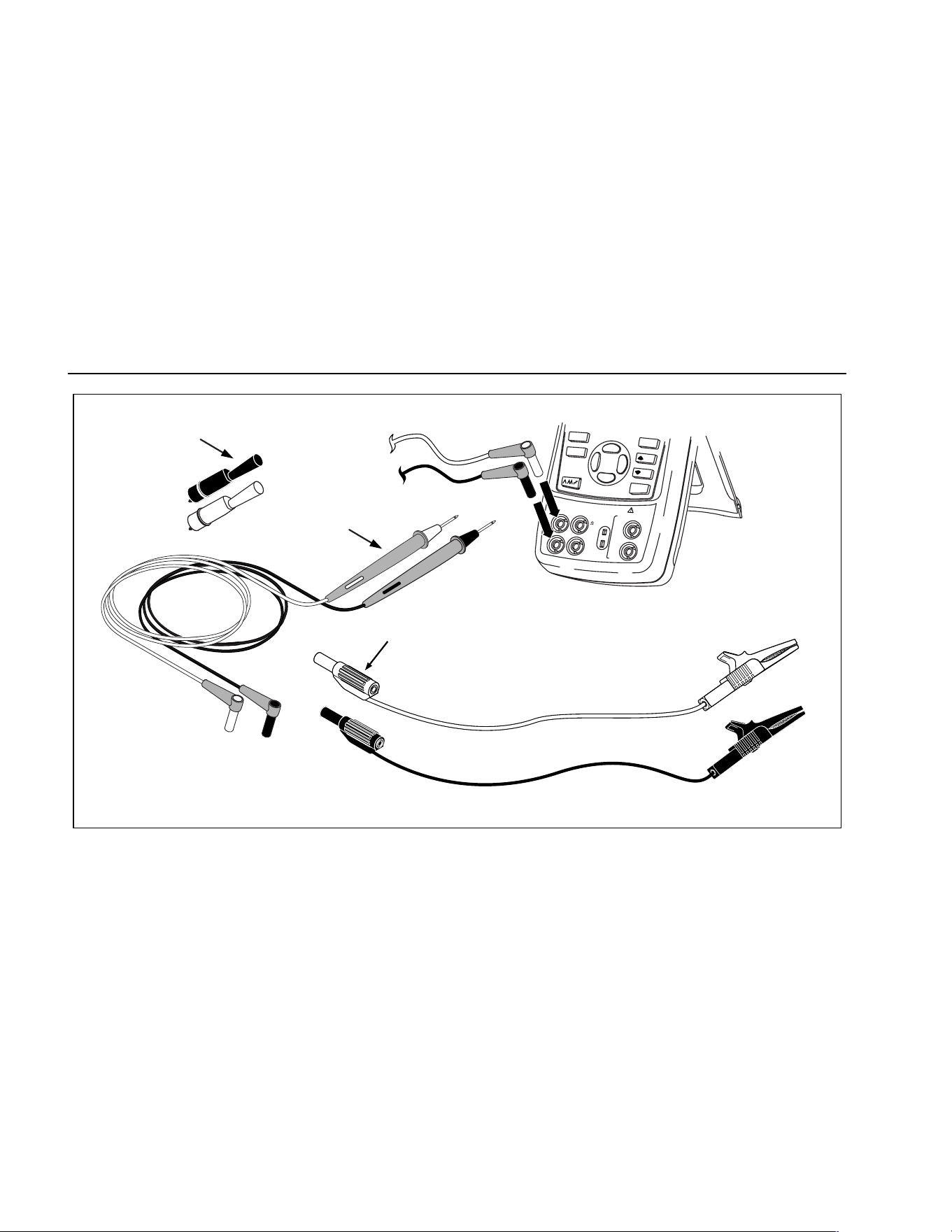
725
Users Manual
6
100%
25%
25%
RECALL
STORE
SETUP
0%
Stackable
Test Leads
TL75
Test Lead Set
AC72
Alligator Clips
V
mA
MEASURE
SOURCE / M
EASURE
30V MAX ALL TERMINALS
4W
3W
V
Hz
RTD
mA
+
mA
-
TC
COM
COM
LOOP
sh01f.eps
Figure 1. Standard Equipment
1.888.610.7664 sales@GlobalTestSupply.com
Fluke-Direct.com
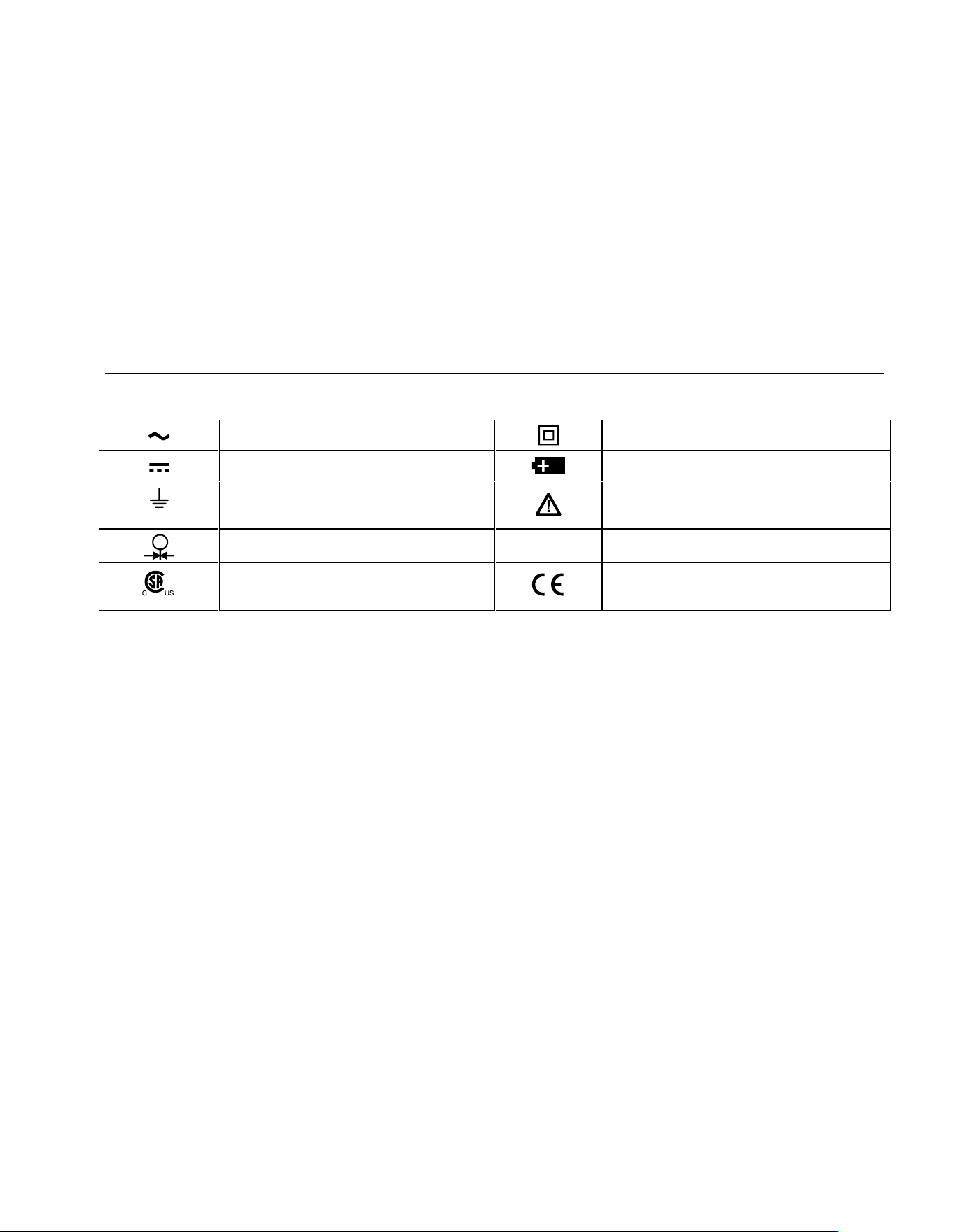
Safety Information
7
Table 2. International Symbols
AC - Alternating current Double insulated
DC - Direct current Battery
Earth ground Refer to the manual for information about
this feature.
Pressure
O
ON/OFF
Conforms to Canadian Standards
Association directives
Conforms to European Union directives
1.888.610.7664 sales@GlobalTestSupply.com
Fluke-Direct.com
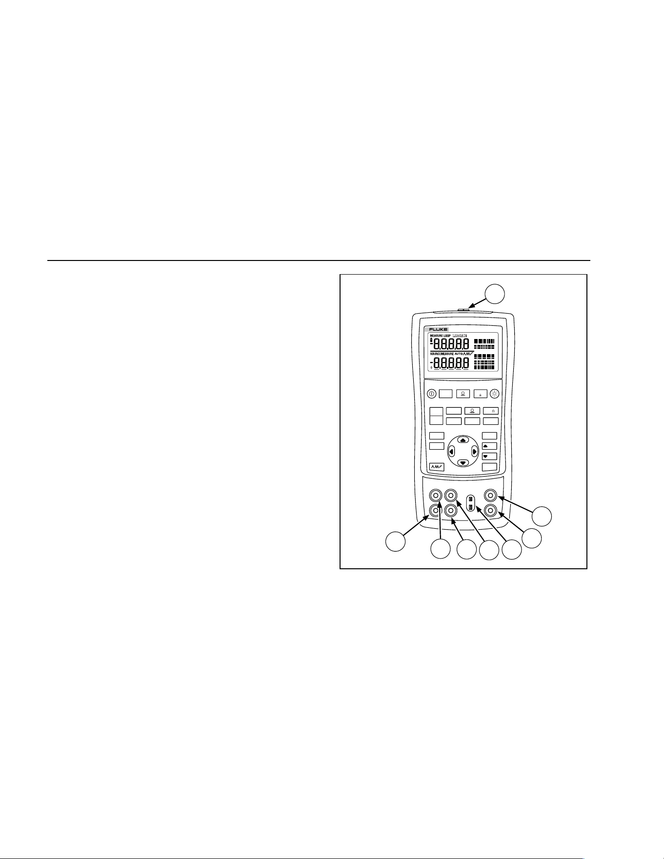
725
Users Manual
8
Getting Acquainted with the Calibrator
Input and Output Terminals
Figure 2 shows the calibrator input and output terminals.
Table 3 explains their use.
V mA
LOO P
V mA
TC RTD
˚
C
˚
F
Hz
100%
25%
25%
RECALL
ZERO
MEAS
SOURCE
STORE
SETUP
0%
MULTIFUNCTION CALIBRATOR
725
8
7
6
5
4
3
2
1
sh05f.eps
Figure 2. Input/Output Terminals and Connectors
1.888.610.7664 sales@GlobalTestSupply.com
Fluke-Direct.com
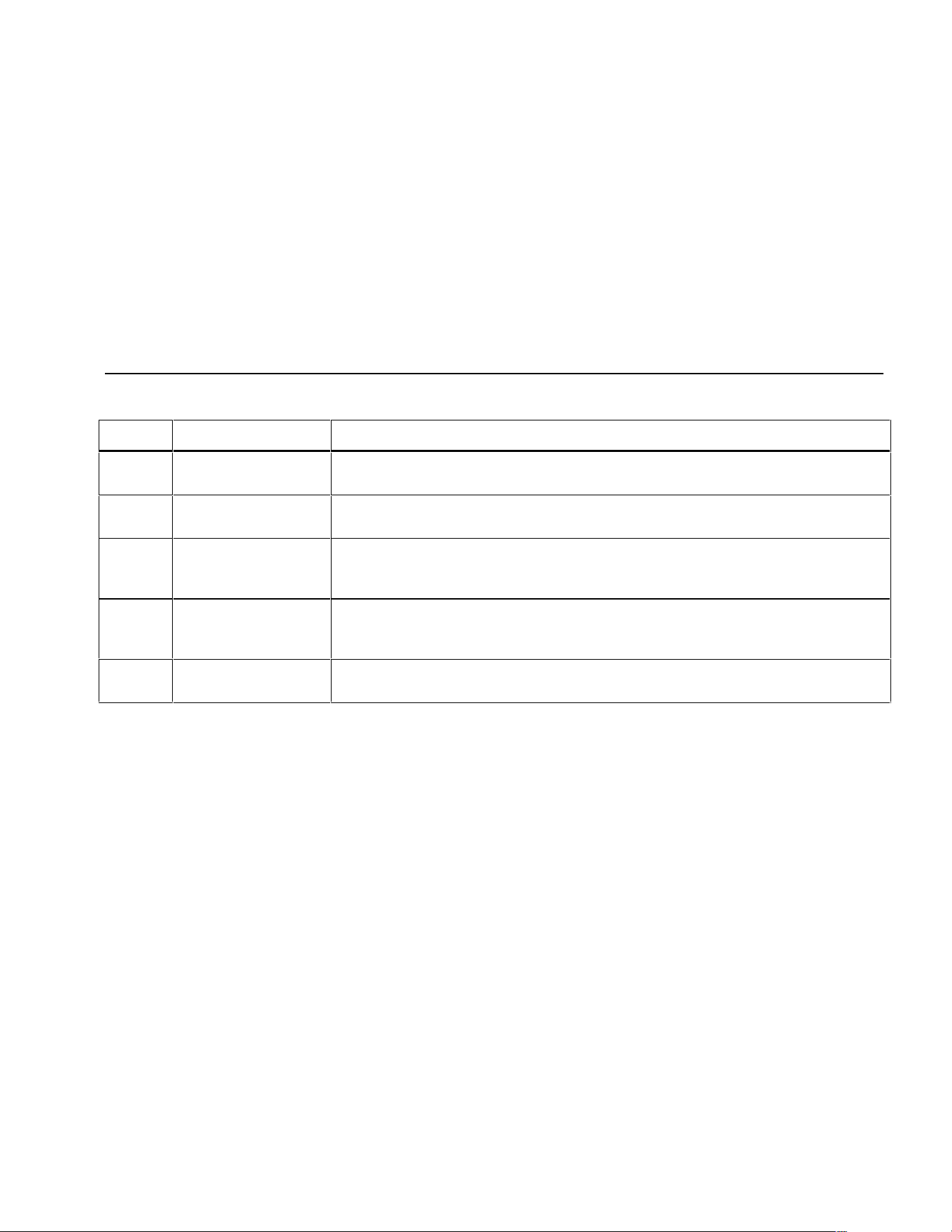
Getting Acquainted with the Calibrator
9
Table 3. Input/Output Terminals and Connectors
No Name Description
A
Pressure module
connector
Connects the calibrator to a pressure module or the calibrator to a PC for a remote
control connection.
B, C
MEASURE V, mA
terminals
Input terminals for measuring voltage, current, and supplying loop power.
D
TC input/output Terminal for measuring or simulating thermocouples. This terminal accepts a miniature
polarized thermocouple plug with flat, in-line blades spaced 7.9 mm (0.312 in) center to
center.
E, F
SOURCE/ MEASURE
V, RTD, Hz, Ω
terminals
Terminals for sourcing or measuring voltage, resistance, frequency, and RTDs.
G, H
SOURCE/ MEASURE
mA terminals, 3W, 4W
Terminals for sourcing and measuring current, and performing 3W and 4W RTD
measurements.
1.888.610.7664 sales@GlobalTestSupply.com
Fluke-Direct.com
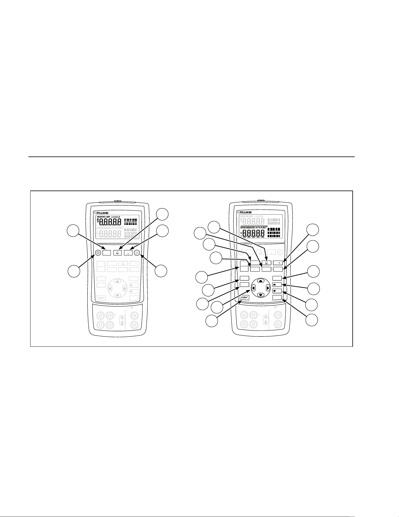
725
Users Manual
10
Keys
Figure 3 shows the calibrator keys and Table 4 explains
their use.
V mA
LOO P
V mA
TC RTD
˚
C
˚
F
Hz
100%
25%
25%
RECALL
ZERO
MEAS
SOURCE
STORE
SETUP
0%
MULTIFUNCTION CALIBRATOR
725
V mA
LOO P
V mA
TC RTD
˚
C
˚
F
Hz
100%
25%
25%
RECALL
ZERO
MEAS
SOURCE
STORE
SETUP
0%
MULTIFUNCTION CALIBRATOR
725
1
8
9
10
2
3
4
6
7
5
12
11
13
14
15
16
17
18
19
20
V
mA
MEASURE
SOURCE / MEASURE
30V MAX ALL TERMINALS
4W
3W
V
Hz
RTD
mA
+
mA
-
TC
COM COM
LOOP
V
mA
MEASURE
SOURCE / MEASURE
30V MAX ALL TERMINALS
4W
3W
V
Hz
RTD
mA
+
mA
-
TC
COM COM
LOOP
sh41f.eps
Figure 3. Keys
1.888.610.7664 sales@GlobalTestSupply.com
Fluke-Direct.com
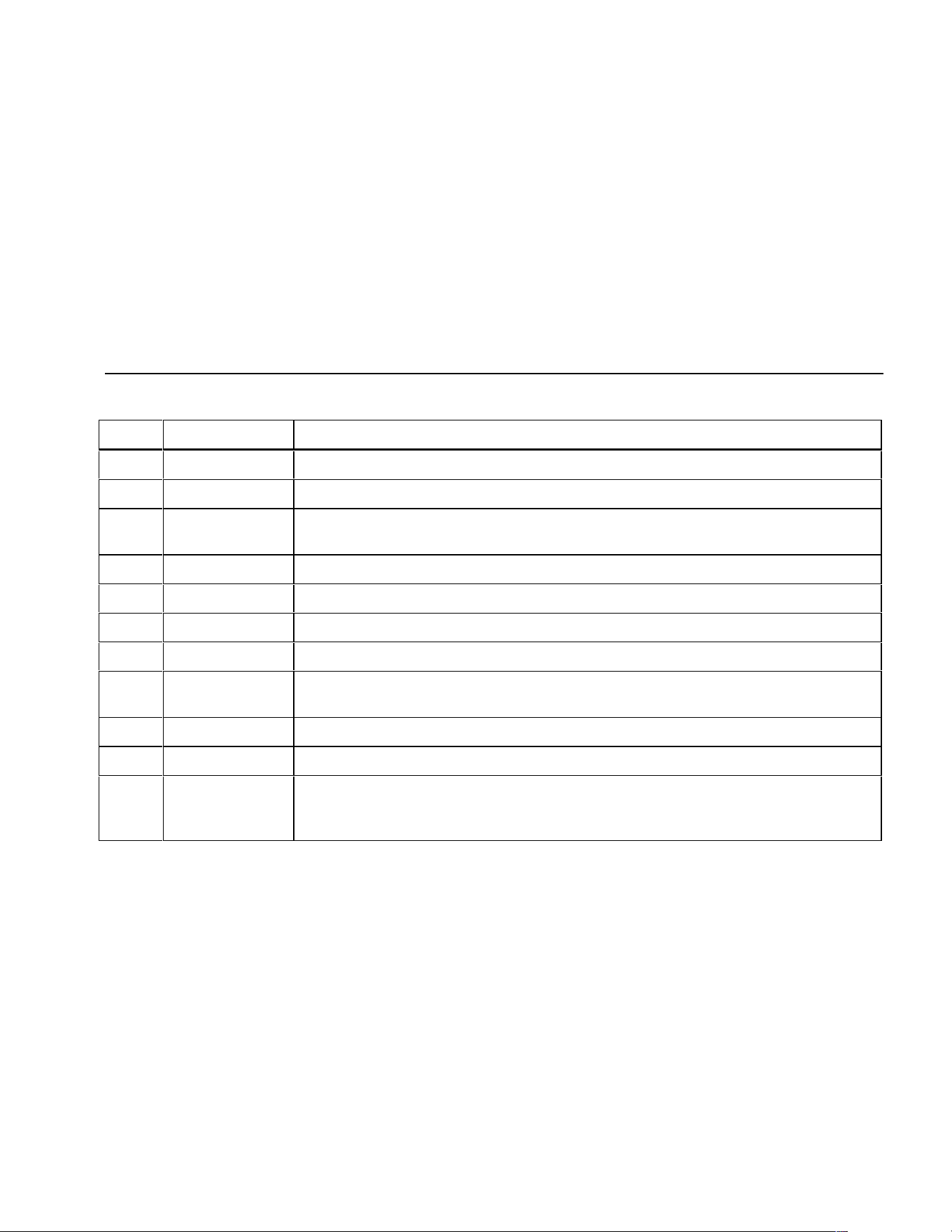
Getting Acquainted with the Calibrator
11
Table 4. Key Functions
No Name Description
A O Turns the power on or off.
B l Selects voltage, mA or Loop Power measurement function in the upper display.
C A Selects the pressure measurement function in the upper display. Repeated pushes cycle
through the different pressure units.
D K Zeros the pressure module reading. This applies to both upper and lower displays.
E C Turns backlight on or off. Turns Contrast Adjust mode on when powering up.
F F Toggles frequency and ohms measurement and sourcing functions.
G D Toggles between Centigrade or Fahrenheit when in TC or RTD functions.
H G Recalls from memory a source value corresponding to 100 % of span and sets it as the
source value. Press and hold to store the source value as the 100 % value.
I H Increments output by 25 % of span.
J I Decrements output by 25 % of span.
K J Recalls from memory a source value corresponding to 0 % of span and sets it as the
source value. Press and hold to store the source value as the 0 % value.
Identifies Firmware version. Press and hold J when powering up.
1.888.610.7664 sales@GlobalTestSupply.com
Fluke-Direct.com
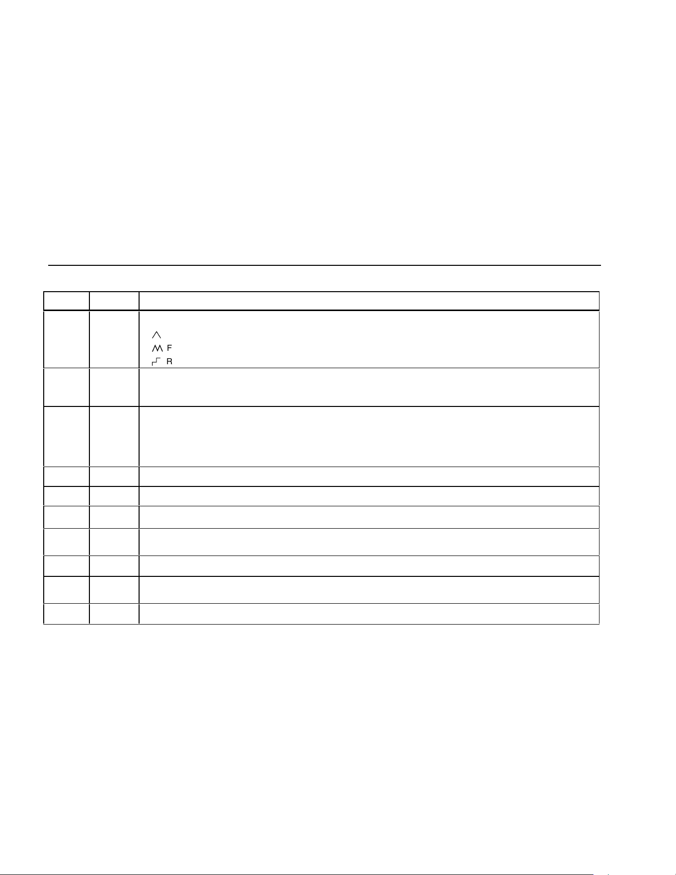
725
Users Manual
12
Table 4. Key Functions (cont.)
No Name Description
L L
Cycles through :
E
Slow repeating 0 % - 100 % - 0 % ramp
P
Fast repeating 0 % - 100 % - 0 % ramp
N
Repeating 0 % - 100 % - 0 % ramp in 25 % steps
AM
AM
OY
OZ
Disables Shut Down Mode
Enables Shut Down Mode
M XW
Y Z
Increases or decreases the source level.
Cycles through the 2-, 3-, and 4-wire selections.
Moves through the memory locations of calibrator setups.
In Contrast Adjustment mode; up-darkens contrast, down-lightens contrast.
N Q
Retrieves a previous calibrator setup from a memory location.
O S
Saves the calibrator setup. Saves Contrast Adjust setup.
P
Cycles the calibrator through MEASURE and SOURCE modes in the lower display.
Q T
Selects TC (thermocouple) measurement and sourcing function in the lower display. Repeated pushes cycle through
the thermocouple types.
R V
Toggles between voltage, mA sourcing, or mA simulate functions in the lower display.
S R
Selects RTD (resistance temperature detector) measurement and sourcing function in lower display. Repeated pushes
cycle through the RTD types.
T U
Selects the pressure measurement and sourcing function. Repeated pushes cycle through the different pressure units.
M
1.888.610.7664 sales@GlobalTestSupply.com
Fluke-Direct.com
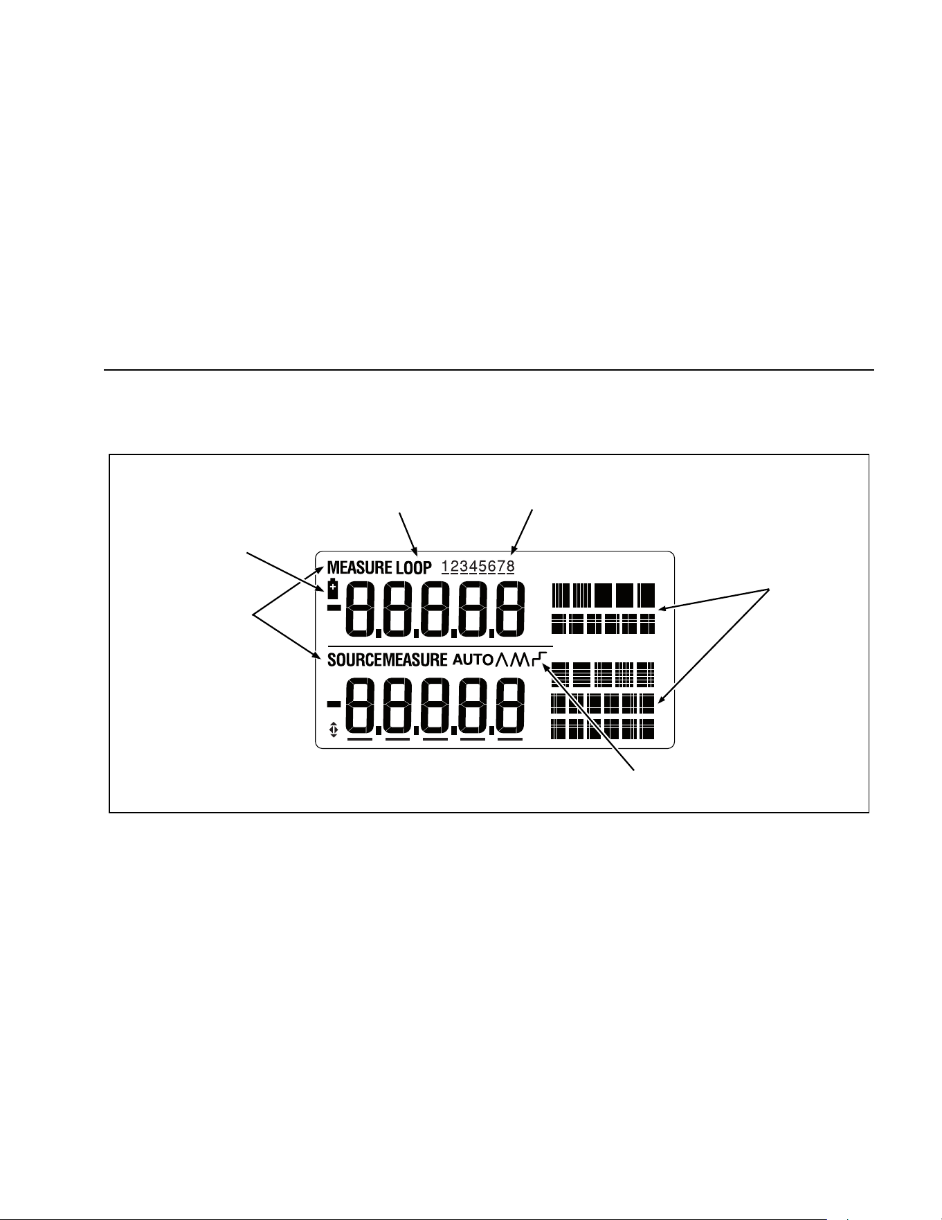
Getting Acquainted with the Calibrator
13
Display
Figure 4 shows the elements of a typical display.
Low Battery
Symbol
Loop
Annunciator
Memory Locations
for Calibrator Setups
Units
Display
Auto
Ramp
Mode
Indicator
sh07f.eps
Figure 4. Elements of a Typical Display
1.888.610.7664 sales@GlobalTestSupply.com
Fluke-Direct.com

725
Users Manual
14
Getting Started
This section acquaints you with some basic operations of
the calibrator.
Proceed as follows to perform a voltage-to-voltage test:
1. Connect the calibrator’s voltage output to its voltage
input as shown in Figure 5.
2. Press O to turn on the calibrator. Press l to
select dc voltage (upper display).
3. If necessary, press M for SOURCE mode (lower
display). The calibrator is still measuring dc voltage,
and you can see the active measurements in the
upper display.
4. Press
V to select dc voltage sourcing.
5. Press
Y and Z to select a digit to change. Press X
to select 1 V for the output value. Press and hold
J to enter 1 V as the 0 % value.
6. Press
X to increase the output to 5 V. Press and
hold
G to enter 5 V as the 100 % value.
7. Press H and I to step between 0 and 100 %
in 25 % step increments.
Shut Down Mode
The calibrator comes with the Shut Down mode
enabled for a time duration set to 30 minutes
(displayed for about 1 second when the calibrator is
initially turned on). When the Shut Down mode is
enabled, the calibrator will automatically shut down
after the time duration has elapsed from the time the
last key was pressed. To disable the Shut Down
mode, press O and Y simultaneously. To enable the
mode, press O and Z simultaneously. To adjust the
time duration, press O and Z simultaneously, then
press X and/or W to adjust the time between 1 and
30 minutes.
1.888.610.7664 sales@GlobalTestSupply.com
Fluke-Direct.com
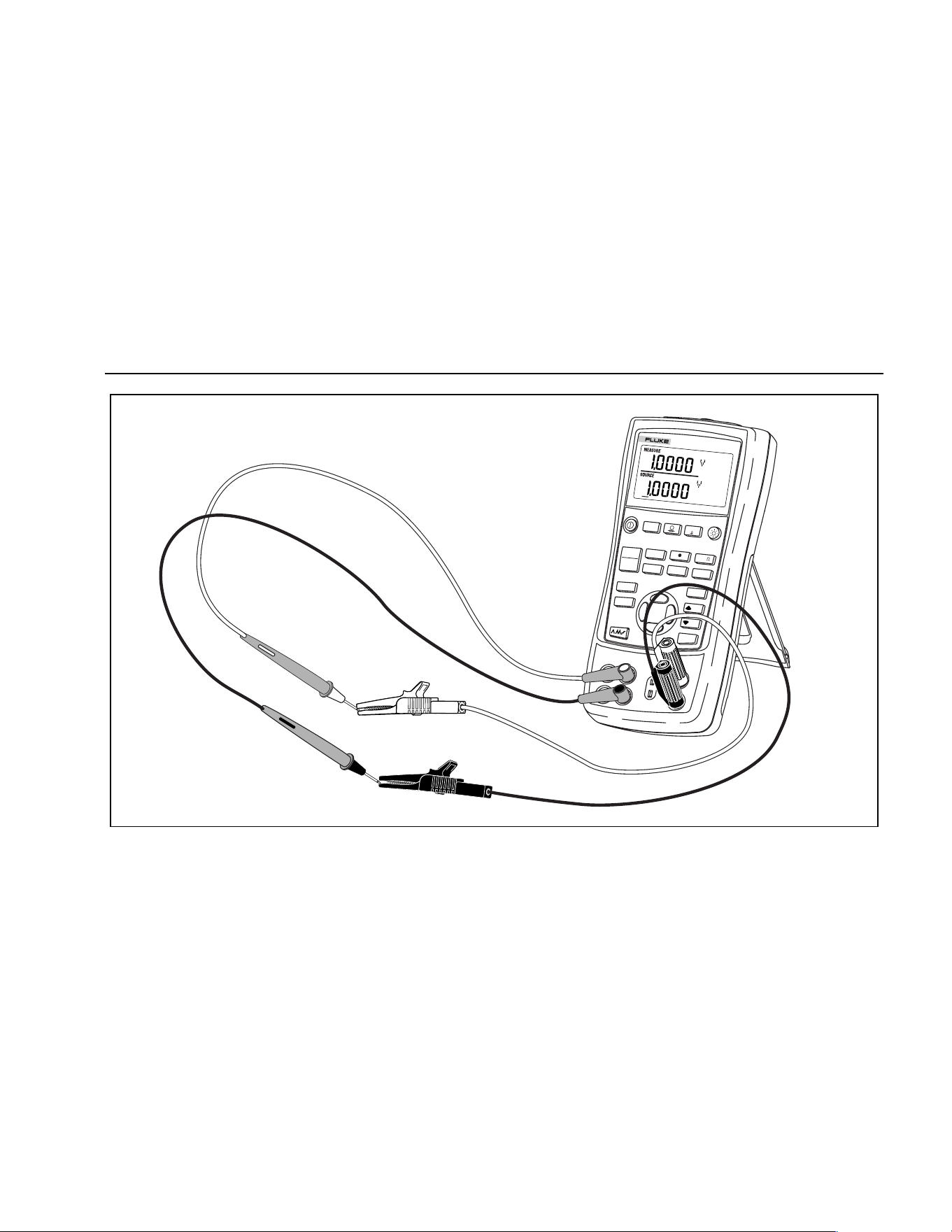
Shut Down Mode
15
V mA
LOOP
V mA
TC
RTD
˚
C
˚
F
Hz
100%
25%
25%
RECALL
ZERO
MEAS
SOURCE
STORE
SETUP
0%
MULTIFUNCTION CALIBRATOR
725
sh39f.eps
Figure 5. Voltage-to-Voltage Test
1.888.610.7664 sales@GlobalTestSupply.com
Fluke-Direct.com
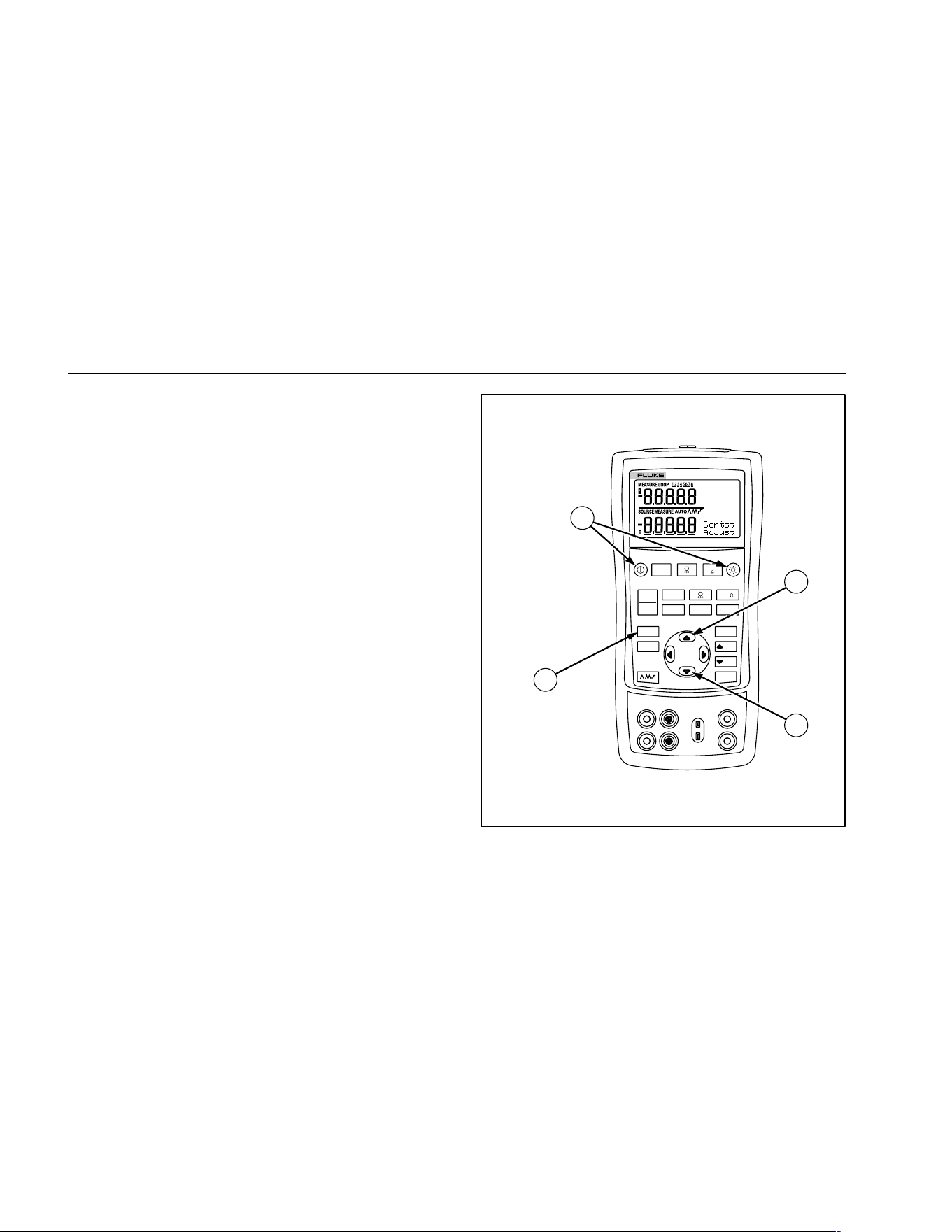
725
Users Manual
16
Contrast Adjustment
Note
Available with V2.1 Firmware or greater. To
identify firmware version, press and hold J
when powering up. The firmware version will be
shown in the upper units display for about 1
second after initialization.
To adjust the contrast, proceed as follows:
1. Press C and O until Contst Adjust is displayed as
shown in Figure 6.
2. Press and hold X to darken contrast.
3. Press and hold W to lighten contrast.
4. Press S to save the contrast level.
V mA
LOO P
V mA
TC RTD
˚
C
˚
F
Hz
100%
25%
25%
RECALL
ZERO
MEAS
SOURCE
STORE
SETUP
0%
MULTIFUNCTION CALIBRATOR
725
1
4
2
3
sh06f.eps
Figure 6. Adjusting the Contrast
1.888.610.7664 sales@GlobalTestSupply.com
Fluke-Direct.com
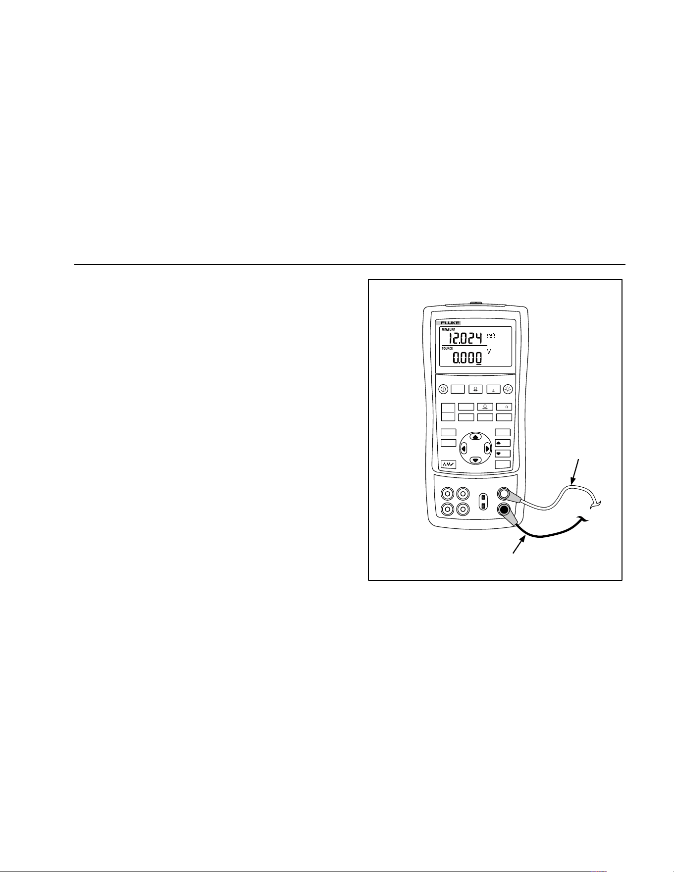
Using Measure Mode
17
Using Measure Mode
Measuring Electrical Parameters (Upper Display)
To measure the current or voltage output of a transmitter,
or to measure the output of a pressure instrument, use the
upper display and proceed as follows:
1. Press
l to select volts or current. LOOP should
not be on.
2. Connect the leads as shown in Figure 7.
Current Measurement with Loop Power
The loop power function activates a 24 V supply in series
with the current measuring circuit, allowing you to test a
transmitter when it is disconnected from plant wiring. To
measure current with loop power, proceed as follows:
1. Connect the calibrator to the transmitter current loop
terminals as shown in Figure 8.
2. Press
l while the calibrator is in current
measurement mode. LOOP appears and an internal
24 V loop supply turns on.
V mA
LOO P
V mA
TC RTD
˚
C
˚
F
Hz
100%
25%
25%
RECALL
ZERO
MEAS
SOURCE
STORE
SETUP
0%
MULTIFUNCTION CALIBRATOR
725
Black
Red
sh42f.eps
Figure 7. Measuring Voltage and Current Output
1.888.610.7664 sales@GlobalTestSupply.com
Fluke-Direct.com
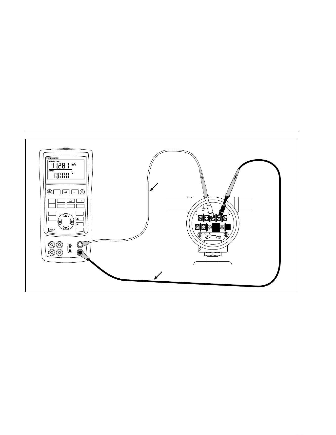
725
Users Manual
18
Red
TEST DC PWR
+–+–
–+
Black
V mA
LOO P
V mA
TC RTD
˚
C
˚
F
Hz
100%
25%
25%
RECALL
ZERO
MEAS
SOURCE
STORE
SETUP
0%
MULTIFUNCTION CALIBRATOR
725
sh18f.eps
Figure 8. Connections for Supplying Loop Power
1.888.610.7664 sales@GlobalTestSupply.com
Fluke-Direct.com
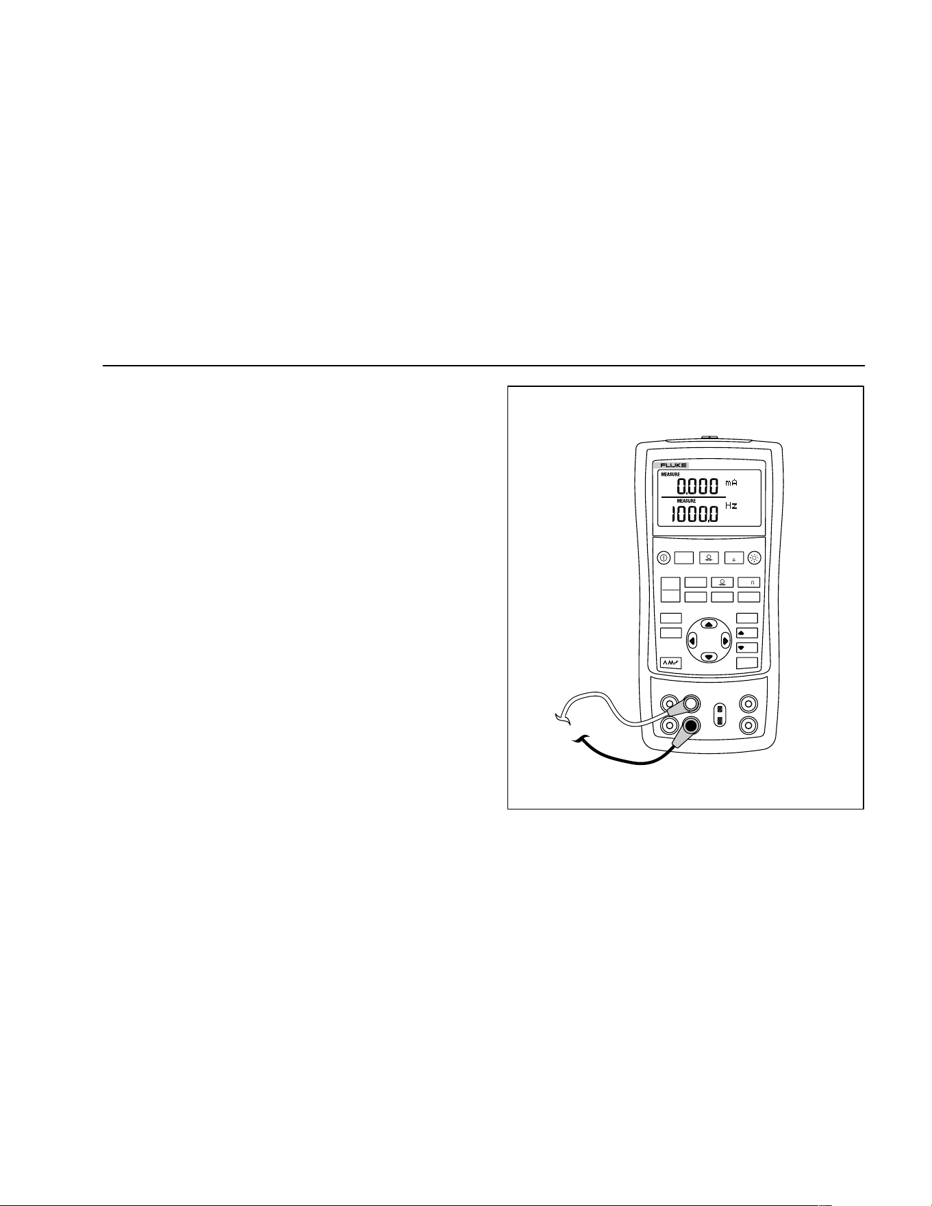
Using Measure Mode
19
Measuring Electrical Parameters (Lower Display)
To measure the electrical parameters using the lower
display, proceed as follows:
1. Connect the calibrator as shown in Figure 9.
2. If necessary, press
M for MEASURE mode (lower
display)
3. Press
V for dc voltage or current, or F for
frequency or resistance.
V mA
LOO P
V mA
TC RTD
˚
C
˚
F
Hz
100%
25%
25%
RECALL
ZERO
MEAS
SOURCE
STORE
SETUP
0%
MULTIFUNCTION CALIBRATOR
725
sh43f.eps
Figure 9. Measuring Electrical Parameters
1.888.610.7664 sales@GlobalTestSupply.com
Fluke-Direct.com

725
Users Manual
20
Measuring Temperature
Using Thermocouples
The calibrator supports ten standard thermocouples,
including type E, N, J, K, T, B, R, S, L, or U. Table 5
summarizes the ranges and characteristics of the
supported thermocouples.
To measure temperature using a thermocouple, proceed
as follows:
1. Attach the thermocouple leads to the appropriate TC
miniplug, then to the TC input/output as shown in
Figure 10. One pin is wider than the other. Do not try
to force a miniplug in the wrong polarization.
Note
If the calibrator and the thermocouple plug are at
different temperatures, wait one minute or more
for the connector temperature to stabilize after
you plug the miniplug into the TC input/output.
2. If necessary, press
M for MEASURE mode.
3. Press T for the TC display. If desired, continue
pressing this key to select the desired thermocouple
type.
If necessary, you can toggle between °C or °F
temperature units by pressing
D.
1.888.610.7664 sales@GlobalTestSupply.com
Fluke-Direct.com
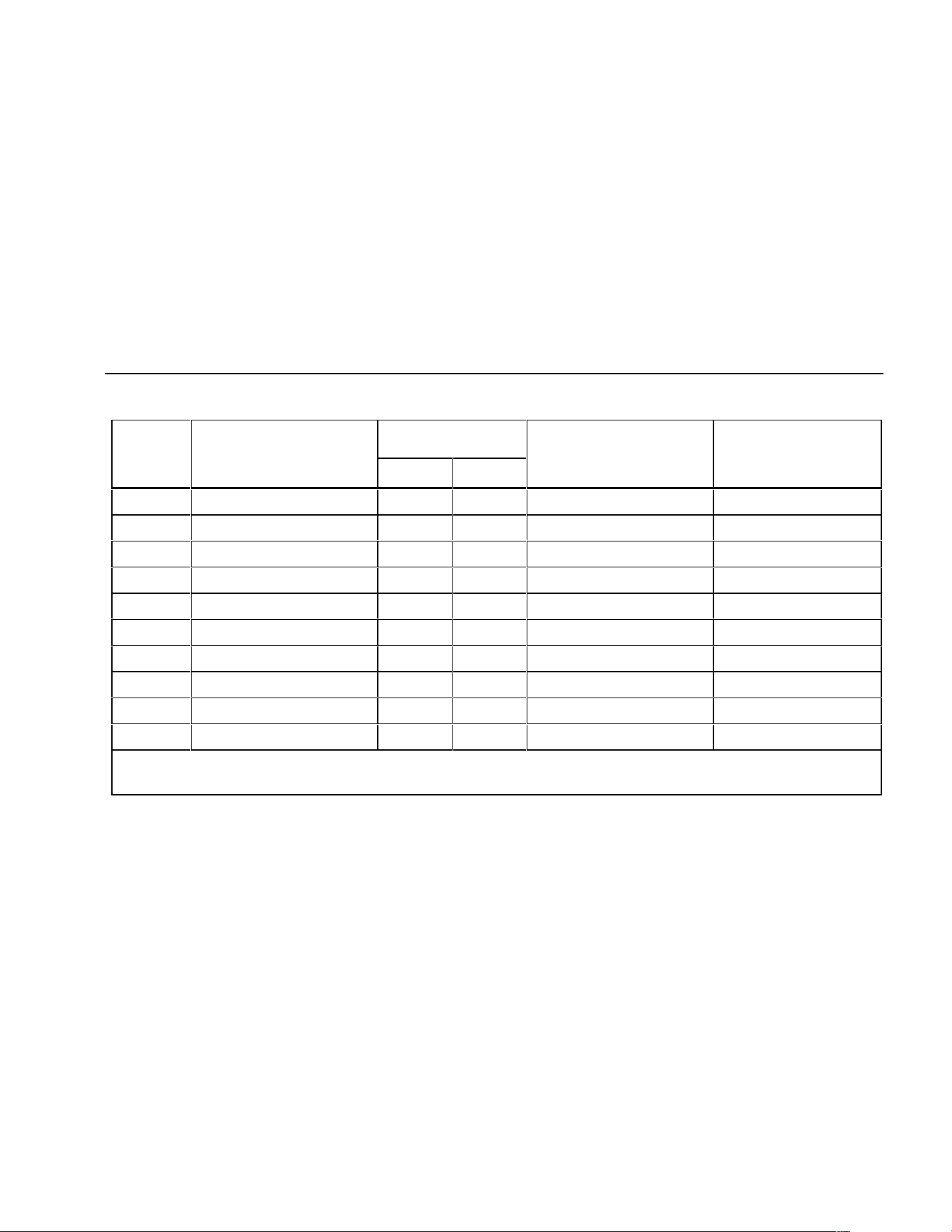
Using Measure Mode
21
Table 5. Thermocouple Types Accepted
Type Positive Lead
Positive Lead (H)
Color Negative Lead Specified Range
Material
ANSI* IEC**
Material (°C)
E Chromel Purple Violet Constantan -200 to 950
N Ni-Cr-Si Orange Pink Ni-Si-Mg -200 to 1300
J Iron White Black Constantan -200 to 1200
K Chromel Yellow Green Alumel -200 to 1370
T Copper Blue Brown Constantan -200 to 400
B Platinum (30 % Rhodium) Gray Platinum (6 % Rhodium) 600 to 1800
R Platinum (13 % Rhodium) Black Orange Platinum -20 to 1750
S Platinum (10 % Rhodium) Black Orange Platinum -20 to 1750
L Iron Constantan -200 to 900
U Copper Constantan -200 to 400
*American National Standards Institute (ANSI) device negative lead (L) is always red.
**International Electrotechnical Commission (IEC) device negative lead (L) is always white.
1.888.610.7664 sales@GlobalTestSupply.com
Fluke-Direct.com
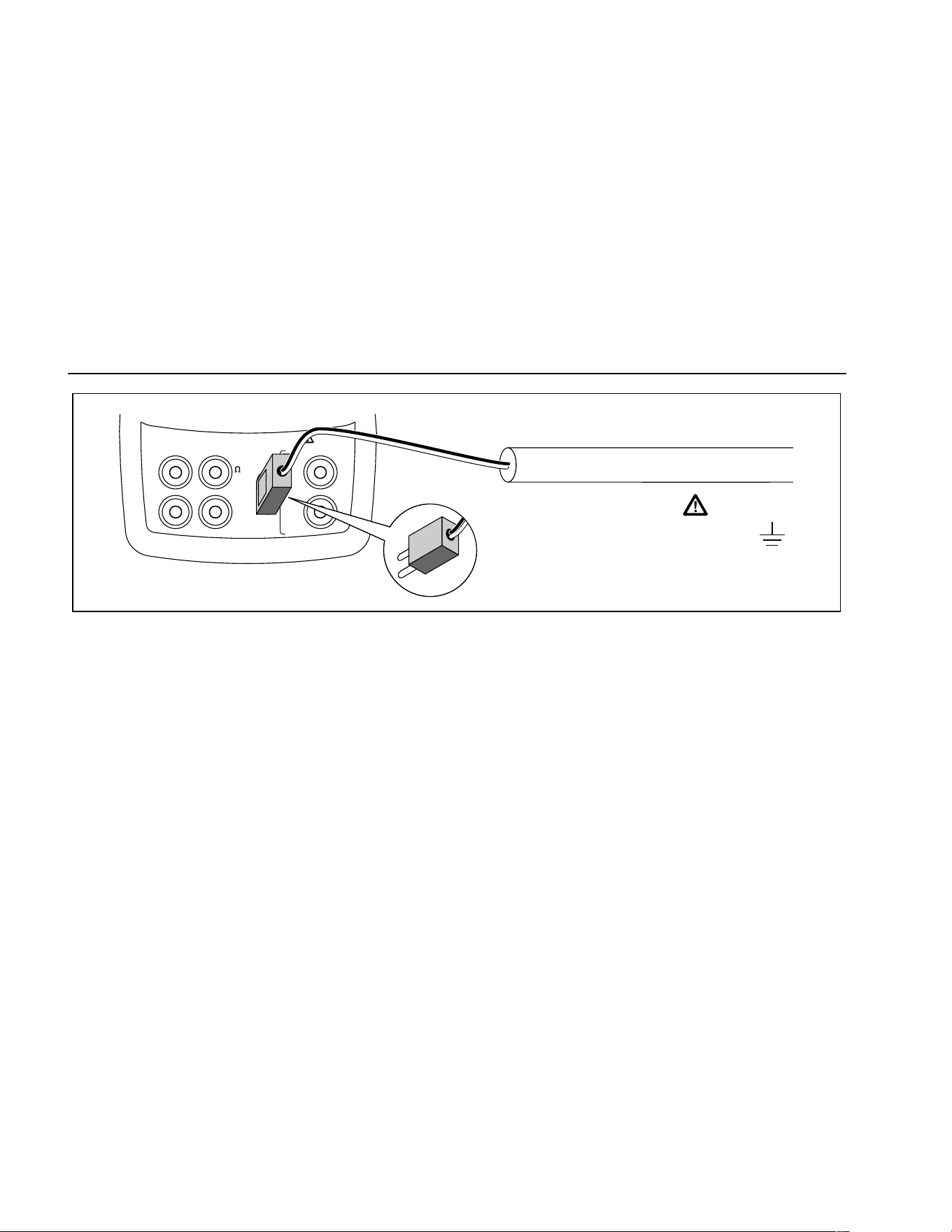
725
Users Manual
22
V
mA
MEASURE
SOURCE / MEASURE
30V MAX ALL TERMINALS
4W
3W
V
Hz
RTD
mA
+
mA
-
TC
COM COM
LOOP
Process Temperature
Warning
30 V maximum to
TC
TC Miniplug
sh12f.eps
Figure 10. Measuring Temperature with a Thermocouple
1.888.610.7664 sales@GlobalTestSupply.com
Fluke-Direct.com

Using Measure Mode
23
Using Resistance-Temperature Detectors (RTDs)
The calibrator accepts RTD types shown in Table 6. RTDs
are characterized by their resistance at 0 °C (32 °F),
which is called the “ice point” or R
0
. The most common R
0
is 100 Ω. The calibrator accepts RTD measurement inputs
in two-, three-, or four-wire connections, with the
three-wire connection the most common. A four-wire
configuration provides the highest measurement
precision, and two-wire provides the lowest measurement
precision.
To measure temperature using an RTD input, proceed as
follows:
1. If necessary, press
M for MEASURE mode.
2. Press
R for the RTD display. If desired, continue
pressing this key to select the desired RTD type.
3. Press
X or W to select a 2-, 3-, or 4- wire
connection.
4. Attach the RTD to input terminals as shown in
Figure 11.
5. If necessary, you can toggle between °C or °F
temperature units by pressing
D.
1.888.610.7664 sales@GlobalTestSupply.com
Fluke-Direct.com
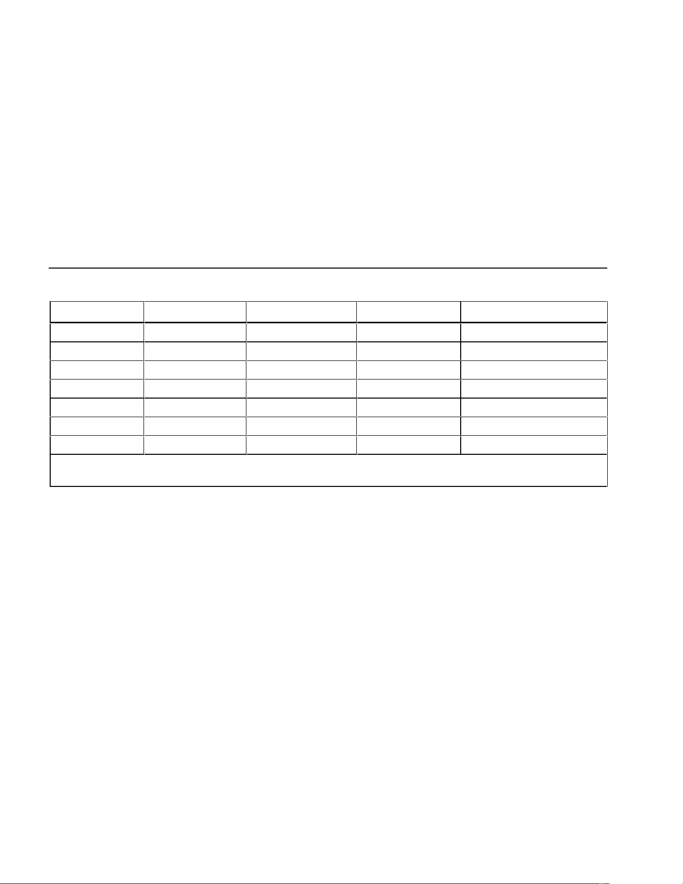
725
Users Manual
24
Table 6. RTD Types Accepted
RTD Type Ice Point (R
0
) Material α Range (°C)
Pt100 (3926) 100 Ω Platinum 0.003926 Ω/°C -200 to 630
Pt100 (385) 100 Ω Platinum 0.00385 Ω/°C -200 to 800
Ni120 (672) 120 Ω Nickel 0.00672 Ω/°C -80 to 260
Pt200 (385) 200 Ω Platinum 0.00385 Ω/°C -200 to 630
Pt500 (385) 500 Ω Platinum 0.00385 Ω/°C -200 to 630
Pt1000 (385) 1000 Ω Platinum 0.00385 Ω/°C -200 to 630
Pt100 (3916) 100 Ω Platinum 0.003916 Ω/°C -200 to 630
The Pt100 commonly used in U.S. industrial applications is Pt100 (3916), α = 0.003916 Ω/°C. (Also designated as JIS
curve.) The IEC standard RTD is the Pt100 (385), α = 0.00385 Ω/°C.
1.888.610.7664 sales@GlobalTestSupply.com
Fluke-Direct.com
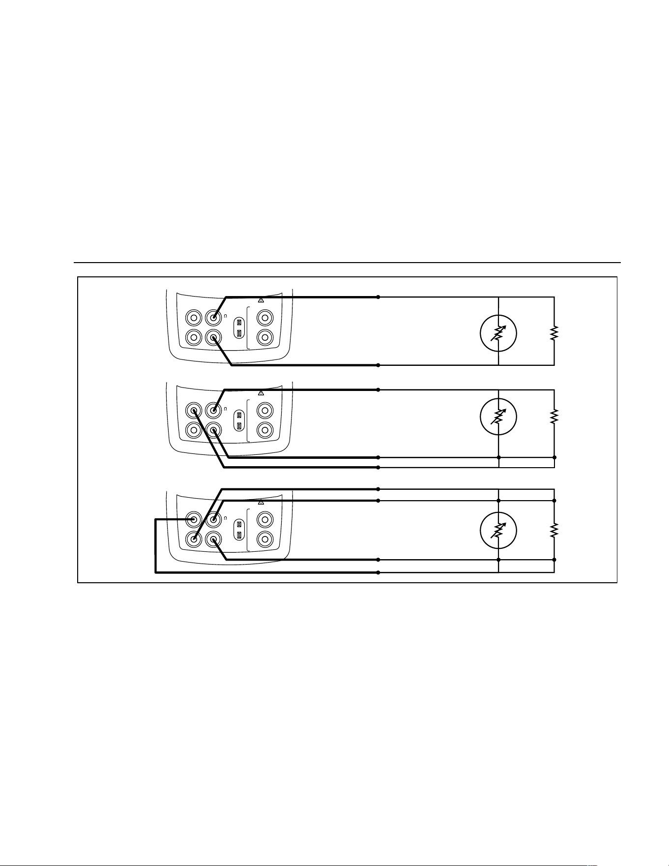
Using Measure Mode
25
RTD
Resistance
to be
measured
RTD
RTD
2W
3W
4W
V
mA
MEASURE
SOURCE / MEASURE
30V MAX ALL TERMINALS
4W
3W
V
Hz
RTD
mA
+
mA
-
TC
COM COM
LOOP
V
mA
MEASURE
SOURCE / MEASURE
30V MAX ALL TERMINALS
4W
3W
V
Hz
RTD
mA
+
mA
-
TC
COM COM
LOOP
V
mA
MEASURE
SOURCE / MEASURE
30V MAX ALL TERMINALS
4W
3W
V
Hz
RTD
mA
+
mA
-
TC
COM COM
LOOP
sh15f.eps
Figure 11. Measuring Temperature with an RTD, Measuring 2-, 3-, and 4-Wire Resistance
1.888.610.7664 sales@GlobalTestSupply.com
Fluke-Direct.com
725
Users Manual
26
Measuring Pressure
Many ranges and types of pressure modules are available
from Fluke. See “Accessories” near the back of this
manual. Before you use a pressure module, read its
instruction sheet. The modules vary in use, media, and
accuracy.
Figure 12 shows the gage and differential modules.
Differential modules also work in gage mode by leaving
the low fitting open to atmosphere.
To measure pressure, attach the appropriate pressure
module for the process pressure to be tested
Proceed as follows to measure pressure:
W Warning
To avoid a violent release of pressure in a
pressurized system, shut off the valve and
slowly bleed off the pressure before you
attach the pressure module to the pressure
line.
Differential
HighLow
15 PSID/G
BURST PRESSURE 45 PSIG
PRESSURE MODULE
700
P
04
1 bar100 kPa
RANGE
Gage
RANGE
100 PSIG
BURST PRESSURE 300 PSIG
PRESSURE MODULE
700
P
06
7 bar700 kPa
gj11f.eps
Figure 12. Gage and Differential Pressure Modules
Caution
To avoid mechanically damaging the
pressure module, never apply more than
10 ft.-lb. (13.5 Nm) of torque between the
pressure module fittings, or between the
fittings and the body of the module. Always
apply appropriate torque between the
pressure module fitting and connecting
fittings or adapters.
1.888.610.7664 sales@GlobalTestSupply.com
Fluke-Direct.com

Using Measure Mode
27
To avoid damaging the pressure module from
overpressure, never apply pressure above the
rated maximum printed on the pressure
module.
To avoid damaging the pressure module from
corrosion, use it only with specified
materials. Refer to the printing on the
pressure module or the pressure module
instruction sheet for the acceptable material
compatibility.
1. Connect a pressure module to the calibrator as
shown in Figure 13. The threads on the pressure
modules accept standard ¼ NPT pipe fittings. Use the
supplied ¼ NPT to ¼ ISO adapter if necessary.
2. Press
A. The calibrator automatically senses
which pressure module is attached and sets its range
accordingly.
3. Zero the pressure module as described in the
module’s Instruction Sheet. Modules vary in zeroing
procedures depending on module type, but all require
pressing
K.
If desired, continue pressing
A to change pressure
display units to psi, mmHg, inHg, cmH
2
O@4 °C,
cmH
2
O@20 °C, inH
2
O@4 °C, inH
2
O@20 °C, mbar,
bar, kg/cm
2
, or kPa.
Zeroing with Absolute Pressure Modules
To zero, adjust the calibrator to read a known pressure.
This can be barometric pressure, if it is accurately known,
for all but the 700PA3 module. The maximum range of
700PA3 is 5 psi; therefore the reference pressure must be
applied with a vacuum pump. An accurate pressure
standard can also apply a pressure within range for any
absolute pressure module. To adjust the calibrator
reading, proceed as follows:
1. Press K, REF Adjust will appear to the right of the
pressure reading.
2. Use X to increase or W to decrease the calibrator
reading to equal the reference pressure.
3. Press Kagain to exit zeroing procedure.
The calibrator stores and automatically reuses the zero
offset correction for one absolute pressure module so that
the module is not rezeroed every time you use it.
1.888.610.7664 sales@GlobalTestSupply.com
Fluke-Direct.com
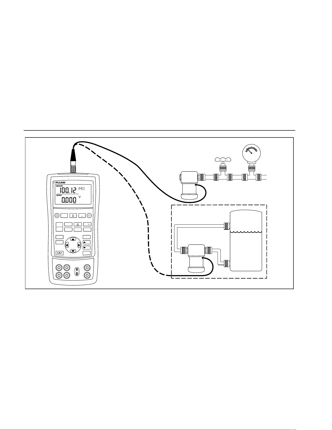
725
Users Manual
28
Differential
Module
Tank
HL
Isolation
Valve
Gage
Module
V mA
LOO P
V mA
TC RTD
˚
C
˚
F
Hz
100%
25%
25%
RECALL
ZERO
MEAS
SOURCE
STORE
SETUP
0%
MULTIFUNCTION CALIBRATOR
725
sh37f.eps
Figure 13. Connections for Measuring Pressure
1.888.610.7664 sales@GlobalTestSupply.com
Fluke-Direct.com

Using Source Mode
29
Using Source Mode
In SOURCE mode, the calibrator generates calibrated
signals for testing and calibrating process instruments;
supplies voltages, currents, frequencies, and resistances;
simulates the electrical output of RTD and thermocouple
temperature sensors; and measures gas pressure from
an external source, creating a calibrated pressure source.
Sourcing 4 to 20 mA
To select the current sourcing mode, proceed as follows:
1. Connect the test leads in the mA terminals (left
column).
2. If necessary, press
M for SOURCE mode.
3. Press
V for current and enter the desired current
you want by pressing
X and W keys.
Simulating a 4- to 20-mA Transmitter
Simulate is a special mode of operation in which the
calibrator is connected into a loop in place of a
transmitter and supplies a known, settable test current.
Proceed as follows:
1. Connect the 24 V loop power source as shown in
Figure 14.
2. If necessary, press
M for SOURCE mode.
3. Press
V until both mA and SIM display.
4. Enter the desired current by pressing
X and W
keys.
Sourcing Other Electrical Parameters
Volts, ohms, and frequency are also sourced and shown
in the lower display.
To select an electrical sourcing function, proceed as
follows:
1. Connect the test leads as shown in Figure 15,
depending on the source function.
2. If necessary, press
Mfor SOURCE mode.
3. Press
V for dc voltage, or F for frequency or
resistance.
4. Enter the desired output value by pressing
X and
W keys. Press Y and Z to select a different digit to
change.
1.888.610.7664 sales@GlobalTestSupply.com
Fluke-Direct.com
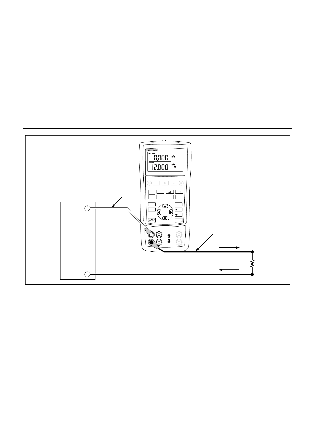
725
Users Manual
30
Loop
Power
Supply
Readout or
Controller
+24 V
Black
Red
+
–
V mA
LOO P
V mA
TC RTD
˚
C
˚
F
Hz
100%
25%
25%
RECALL
ZERO
MEAS
SOURCE
STORE
SETUP
0%
MULTIFUNCTION CALIBRATOR
725
sh17f.eps
Figure 14. Connections for Simulating a 4- to 20-mA Transmitter
1.888.610.7664 sales@GlobalTestSupply.com
Fluke-Direct.com
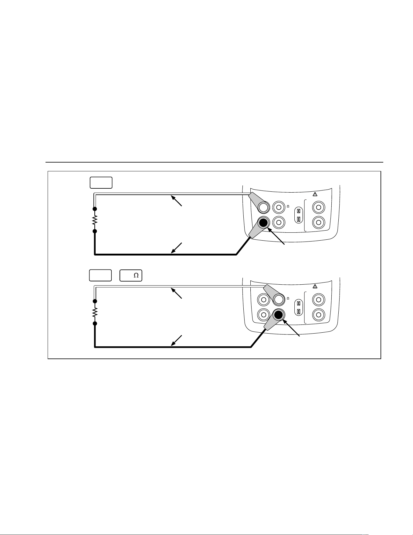
Using Source Mode
31
V
mA
MEASURE
SOURCE / MEASURE
30V MAX ALL TERMINALS
4W
3W
V
Hz
RTD
mA
+
mA
-
TC
COM COM
LOOP
V
mA
MEASURE
SOURCE / MEASURE
30V MAX ALL TERMINALS
4W
3W
V
Hz
RTD
mA
+
mA
-
TC
COM COM
LOOP
Red
Black
+
–
+
–
Red
Black
Common
Common
V
mA
Hz
+ mA
sh16f.eps
Figure 15. Electrical Sourcing Connections
1.888.610.7664 sales@GlobalTestSupply.com
Fluke-Direct.com

725
Users Manual
32
Simulating Thermocouples
Connect the calibrator TC input/output to the instrument
under test with thermocouple wire and the appropriate
thermocouple mini-connector (polarized thermocouple
plug with flat, in-line blades spaced 7.9 mm [0.312 in]
center to center). One pin is wider than the other. Do not
try to force a miniplug in the wrong polarization. Figure 16
shows this connection. Proceed as follows to simulate a
thermocouple:
1. Attach the thermocouple leads to the appropriate TC
miniplug, then to the TC input/output as shown in
Figure 16.
2. If necessary, press
M for SOURCE mode.
3. Press
T for the TC display. If desired, continue
pressing this key to select the desired thermocouple
type.
4. Enter the temperature you want by pressing
X and
W keys. Press Y and Z to select a different digit to
edit.
Simulating RTDs
Connect the calibrator to the instrument under test as
shown in Figure 17. Proceed as follows to simulate an
RTD:
1. If necessary, press
M for SOURCE mode.
2. Press
R for the RTD display.
Note
Use the 3W and 4W terminals for measurement
only, not for simulation. The calibrator simulates
a 2-wire RTD at its front panel. To connect to a 3-
wire or 4-wire transmitter, use the stacking
cables to provide the extra wires. See Figure 17.
3. Enter the temperature you want by pressing
X and
W keys. Press Y and Z to select a different digit to
edit.
4. If the 725 display indicates ExI HI, the excitation
current from your device under test exceeds the limits
of the 725.
1.888.610.7664 sales@GlobalTestSupply.com
Fluke-Direct.com
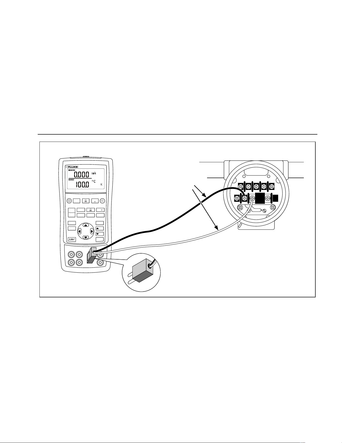
Using Source Mode
33
TEST DC PWR
++–
–+
Color depends
on type of TC
V mA
LOO P
V mA
TC RTD
˚
C
˚
F
Hz
100%
25%
25%
RECALL
ZERO
MEAS
SOURCE
STORE
SETUP
0%
MULTIFUNCTION CALIBRATOR
725
TC
TC Miniplug
sh20f.eps
Figure 16. Connections for Simulating a Thermocouple
1.888.610.7664 sales@GlobalTestSupply.com
Fluke-Direct.com
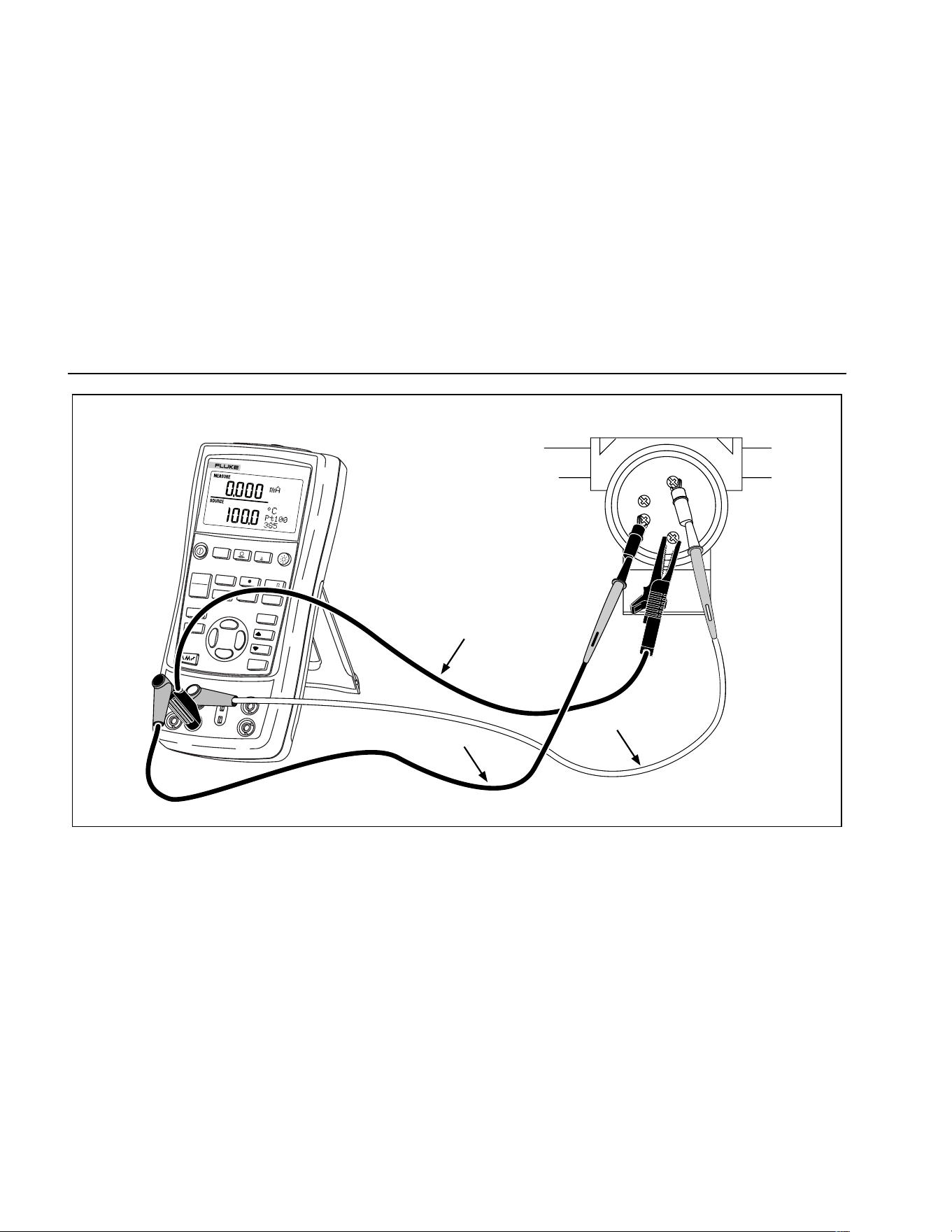
725
Users Manual
34
V mA
LOOP
V mA
TC
RTD
˚
C
˚
F
Hz
100%
25%
25%
RECALL
ZERO
MEAS
SOURCE
STORE
SETUP
0%
MULTIFUNCTION CALIBRATOR
725
BLACK
SENSOR TERMINALS
BLACK
RED
1
2
3
4
sh40f.eps
Figure 17. Connections for Simulating 3-Wire RTD
1.888.610.7664 sales@GlobalTestSupply.com
Fluke-Direct.com

Using Source Mode
35
Sourcing Pressure
The calibrator sources pressure by measuring pressure
supplied by a pump or other sources, and displaying the
pressure in the SOURCE field. Figure 20 shows how to
connect a pump to a Fluke pressure module which makes
it a calibrated source.
Many ranges and types of pressure modules are available
from Fluke. See “Accessories” near the back of this
manual. Before you use a pressure module, read its
Instruction Sheet. The modules vary in use, media, and
accuracy.
Attach the appropriate pressure module for the process
pressure to be tested.
Proceed as follows to source pressure:
WWarning
To avoid a violent release of pressure in a
pressurized system, shut off the valve and
slowly bleed off the pressure before you
attach the pressure module to the pressure
line.
Caution
To avoid mechanically damaging the
pressure module, never apply more than
10 ft.-lb. (13.5 Nm) of torque between the
pressure module fittings, or between the
fittings and the body of the module. Always
apply appropriate torque between the
pressure module fitting and connecting
fittings or adapters.
To avoid damaging the pressure module from
overpressure, never apply pressure above the
rated maximum printed on the pressure
module.
To avoid damaging the pressure module from
corrosion, use it only with specified
materials. Refer to the printing on the
pressure module or the pressure module
instruction sheet for the acceptable material
compatibility.
1.888.610.7664 sales@GlobalTestSupply.com
Fluke-Direct.com
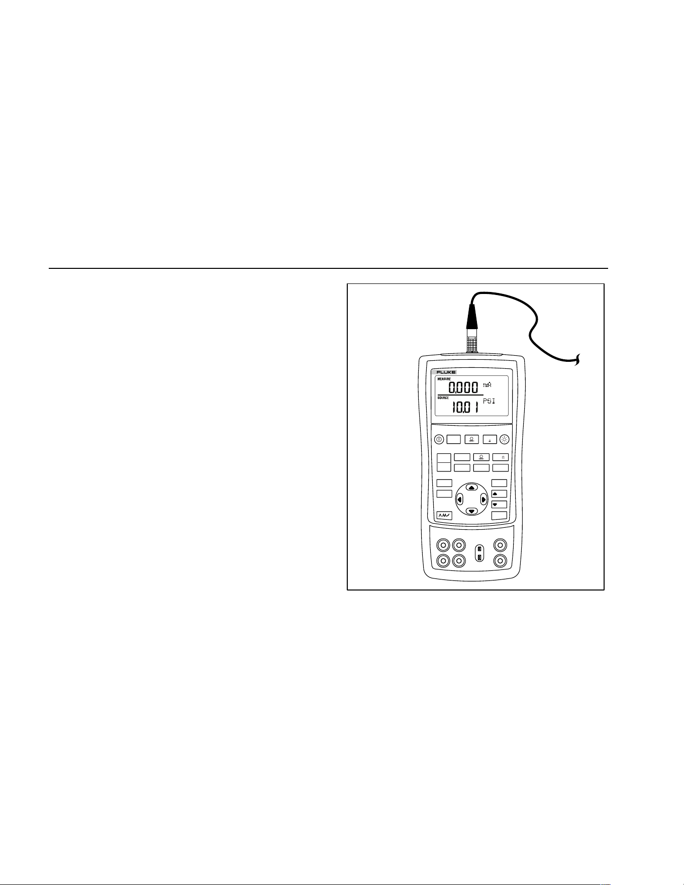
725
Users Manual
36
1. Connect a pressure module to the calibrator as
shown in Figure 18. The threads on the pressure
modules accept standard ¼ NPT pipe fittings. Use the
supplied ¼ NPT to ¼ ISO adapter if necessary.
2. Press
U (lower display). The calibrator
automatically senses which pressure module is
attached and sets its range accordingly.
3. Zero the pressure module as described in the
module’s Instruction Sheet. Modules vary in zeroing
procedures depending on module type.
4. Pressurize the pressure line with the pressure source
to the desired level as shown on the display.
If desired, continue pressing
U to change pressure
display units to psi, mmHg, inHg, cmH
2
O@4 °C,
cmH
2
O@20 °C, inH
2
O@4 °C, inH
2
O@20 °C, mbar,
bar, kg/cm
2
, or kPa.
V mA
LOO P
V mA
TC RTD
˚
C
˚
F
Hz
100%
25%
25%
RECALL
ZERO
MEAS
SOURCE
STORE
SETUP
0%
MULTIFUNCTION CALIBRATOR
725
sh19f.eps
Figure 18. Connections for Sourcing Pressure
1.888.610.7664 sales@GlobalTestSupply.com
Fluke-Direct.com

Setting 0 % and 100 % Output Parameters
37
Setting 0 % and 100 % Output
Parameters
For current output, the calibrator assumes that 0 %
corresponds to 4 mA and 100 % corresponds to 20 mA.
For other output parameters, you must set the 0 % and
100 % points before you can use the step and ramp
functions. Proceed as follows:
1. If necessary, press
M for SOURCE mode.
2. Select the desired source function and use the arrow
keys to enter the value. Our example is temperature
source using 100 °C and 300 °C values for source.
3. Enter 100 °C and press and hold
J to store the
value.
4. Enter in 300 °C and press and hold
G to store the
value.
You can now use this setting for the following:
• Manually stepping an output with 25 % increments.
• Jump between the 0 and 100 % span points by
momentarily pushing
J or G.
Stepping and Ramping the Output
Two features are available for adjusting the value of
source functions.
• Stepping the output manually with the
H and I
keys, or in automatic mode.
• Ramping the output.
Stepping and ramping apply to all functions except
pressure, which requires that you use an external
pressure source.
Manually Stepping the mA Output
To manually step current output you can do the following:
• Use
H or I to step the current up or down in
25 % steps.
• Touch momentarily either
J to go to 0 %, or G
to go to 100 %.
1.888.610.7664 sales@GlobalTestSupply.com
Fluke-Direct.com
725
Users Manual
38
Auto Ramping the Output
Auto ramping gives you the ability to continuously apply a
varying stimulus from the calibrator to a transmitter, while
your hands remain free to test the response of the
transmitter.
When you press
L, the calibrator produces a
continuously repeating 0 % - 100 % - 0 % ramp in your
choice of three ramp waveforms:
•
E 0 % - 100 % - 0 % 40-second smooth ramp
• P 0 % - 100 % - 0 % 15-second smooth ramp
•
N 0 % - 100 % - 0 % Stair-step ramp in 25 %
steps, pausing 5 seconds at each step. Steps are
listed in Table 7.
To exit ramping, press any button.
Table 7. mA Step Values
Step 4 to 20 mA
0 % 4.000
25 % 8.000
50 % 12.000
75 % 16.000
100 % 20.000
Storing and Recalling Setups
You can store up to eight of your settings in a nonvolatile
memory and recall the settings for later use. A low battery
condition or a battery change does not jeopardize the
stored settings. Proceed as follows:
1. After you create a calibrator setup, press
S. In the
display, the memory locations appear.
2. Press
Y or Z to select locations one through eight. An
underscore appears below the selected memory
location.
3. Press S, only the stored memory location will be
displayed.
The setup is stored.
To recall setups, proceed as follows.
1. Press
Q. The memory locations appear on the
display.
2. Press
Y or Z to select the appropriate location and
press
Q.
1.888.610.7664 sales@GlobalTestSupply.com
Fluke-Direct.com

Calibrating a Transmitter
39
Calibrating a Transmitter
Use the measurement (upper display) and source (lower
display) modes to calibrate a transmitter. This section
applies to all but pressure transmitters. The following
example shows how to calibrate a temperature
transmitter.
Connect the calibrator to the instrument under test as
shown in Figure 19. Proceed as follows to calibrate a
transmitter
1. Press
l for current (upper display). If required,
press
l again to activate loop power.
2. Press
T (lower display). If desired, continue
pressing this key to select the desired thermocouple
type.
3. If necessary, press
M for SOURCE mode.
4. Set your zero and span parameters by pressing
X
and W keys. Enter these parameters by pressing and
holding
J and G. For more information on
setting parameters, see “Setting 0 % and 100 %”
earlier in this manual.
5. Perform test checks at 0-25-50-75-100 % points by
pressing
H or I. Adjust the transmitter as
necessary.
1.888.610.7664 sales@GlobalTestSupply.com
Fluke-Direct.com
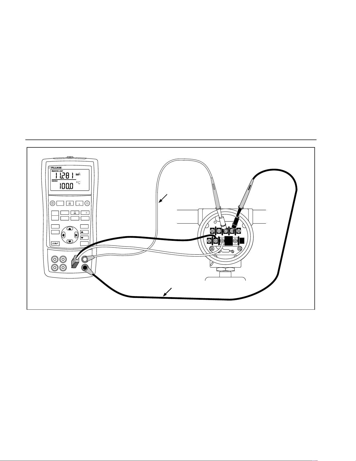
725
Users Manual
40
Red
TEST DC PWR
+–+–
–+
Black
V mA
LOO P
V mA
TC RTD
˚
C
˚
F
Hz
100%
25%
25%
RECALL
ZERO
MEAS
SOURCE
STORE
SETUP
0%
MULTIFUNCTION CALIBRATOR
725
sh44f.eps
Figure 19. Calibrating a Thermocouple Transmitter
1.888.610.7664 sales@GlobalTestSupply.com
Fluke-Direct.com

Calibrating a Pressure Transmitter
41
Calibrating a Pressure Transmitter
The following example shows how to calibrate a pressure
transmitter.
Connect the calibrator to the instrument under test as
shown in Figure 20. Proceed as follows:
1. Press
l for current (upper display). If required,
press
l again to activate loop power.
2. Press
U (lower display).
3. If necessary, press
M for SOURCE mode.
4. Zero the pressure module.
5. Perform checks at 0 % and 100 % of span and adjust
the transmitter as necessary.
1.888.610.7664 sales@GlobalTestSupply.com
Fluke-Direct.com
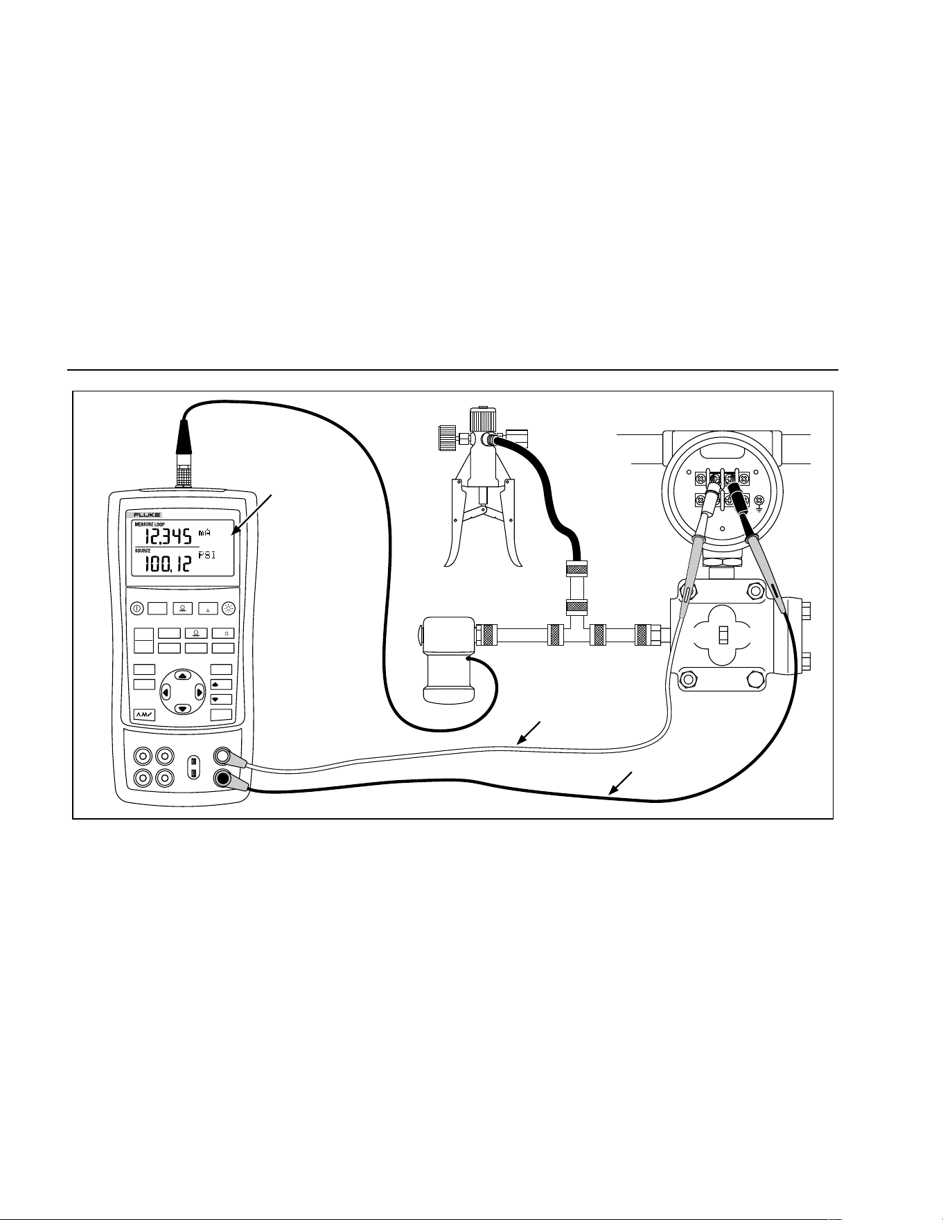
725
Users Manual
42
Hand Pump
SIGNAL
TEST
+
–
Pressure
Module
Red
Black
Measure mA
Source Pressure
24 V Loop Power
Enabled
MULTIFUNCTION CALIBRATOR
725
V mA
LOO P
V mA
TC RTD
˚
C
˚
F
Hz
100%
25%
25%
RECALL
ZERO
MEAS
SOURCE
STORE
SETUP
0%
sh34f.eps
Figure 20. Calibrating a Pressure-to-Current (P/I) Transmitter
1.888.610.7664 sales@GlobalTestSupply.com
Fluke-Direct.com

Calibrating an I/P Device
43
Calibrating an I/P Device
The following test allows you to calibrate a device that
controls pressure. Proceed as follows:
1. Connect the test leads to the instrument under test as
shown in Figure 21. The connections simulate a
current-to-pressure transmitter and measures the
corresponding output pressure.
2. Press
A (upper display).
3. Press
V for sourcing current (lower display).
4. If necessary, press
M for SOURCE mode.
5. Enter the desired current by pressing
X and W
keys. Press Y and Z to select different digits.
1.888.610.7664 sales@GlobalTestSupply.com
Fluke-Direct.com
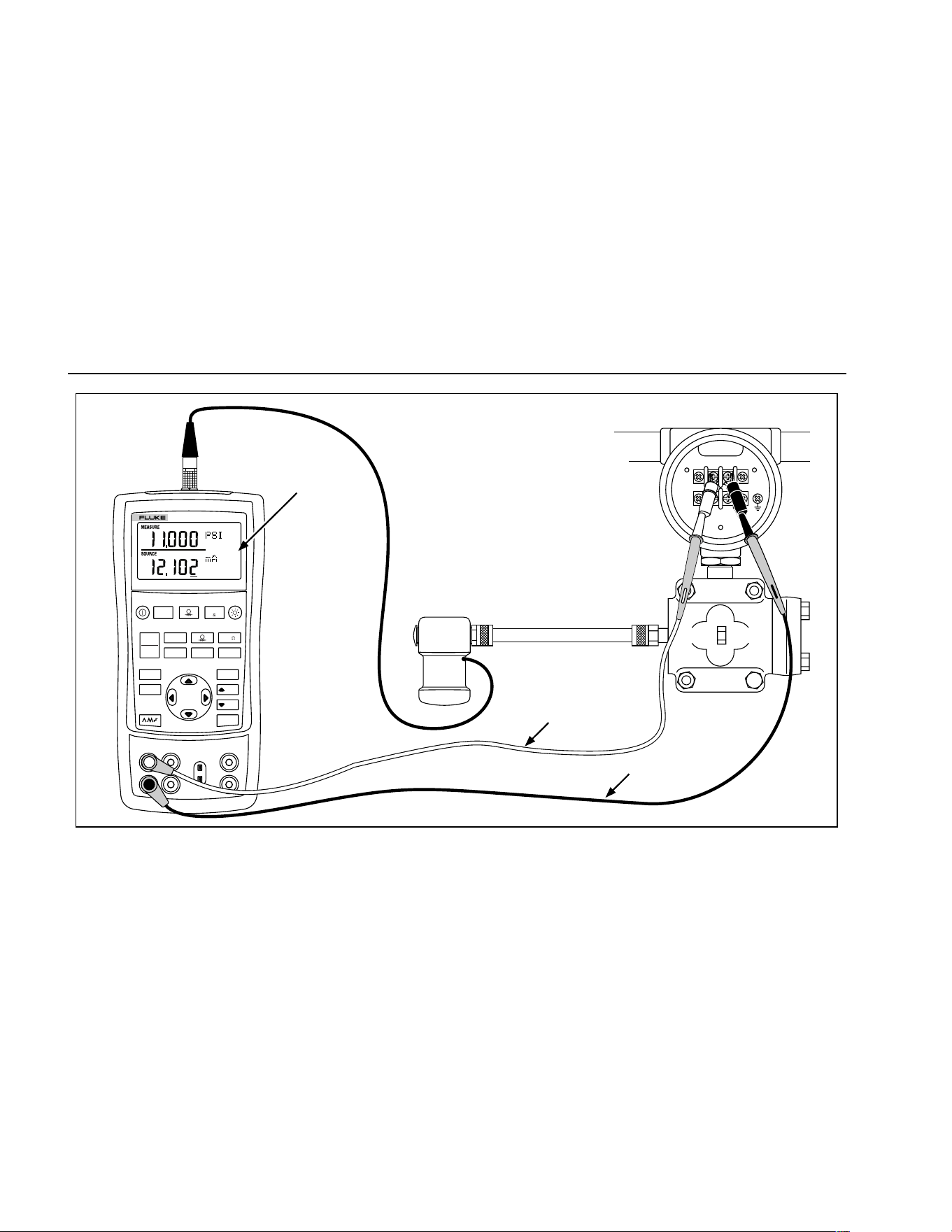
725
Users Manual
44
SIGNAL
TEST
+
–
Pressure
Module
Red
Black
Measure
Pressure
Source mA
V mA
LOO P
V mA
TC RTD
˚
C
˚
F
Hz
100%
25%
25%
RECALL
ZERO
MEAS
SOURCE
STORE
SETUP
0%
MULTIFUNCTION CALIBRATOR
725
sh28f.eps
Figure 21. Calibrating a Current-to-Pressure (I/P) Transmitter
1.888.610.7664 sales@GlobalTestSupply.com
Fluke-Direct.com
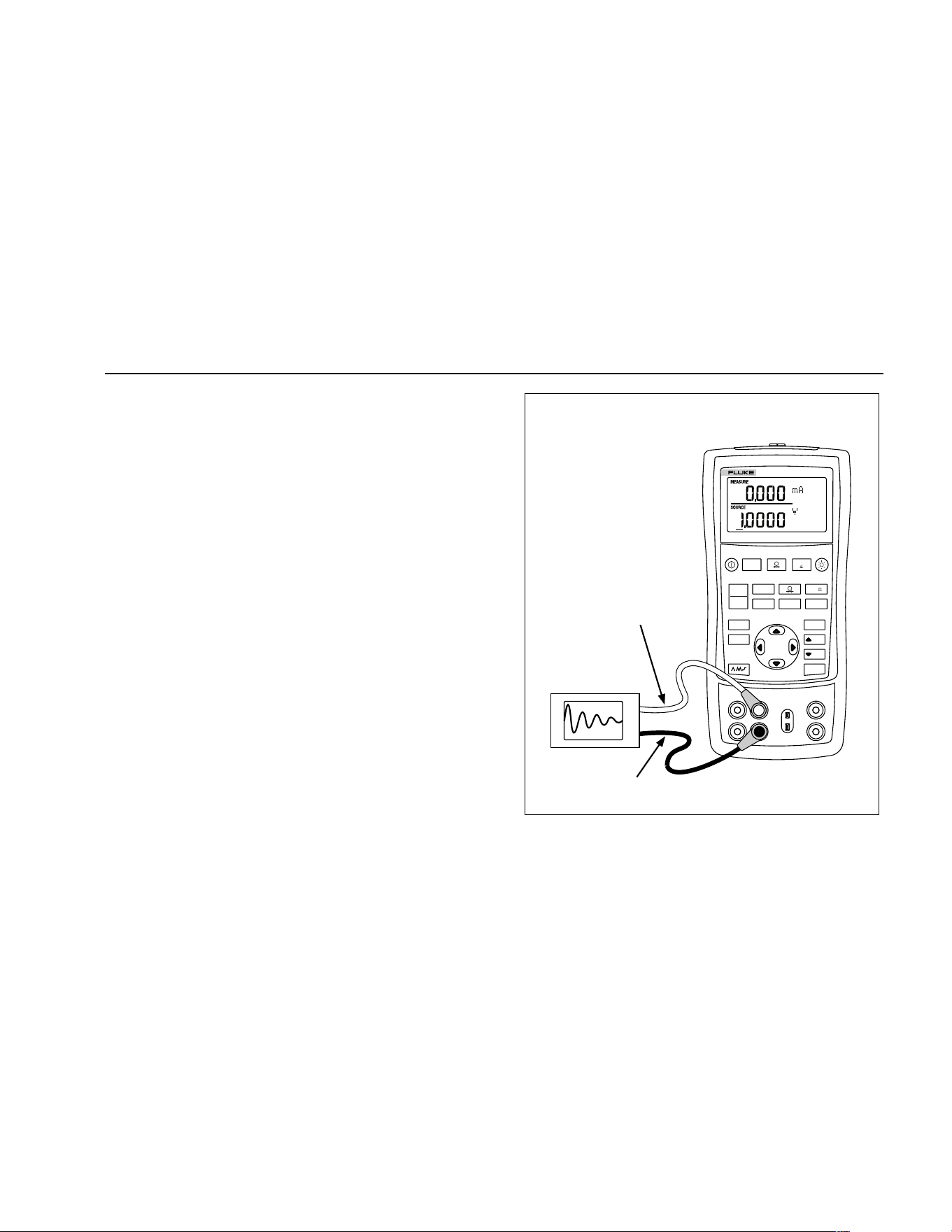
Testing an Output Device
45
Testing an Output Device
Use the source functions to test and calibrate actuators,
recording, and indicating devices. Proceed as follows:
1. Connect the test leads to the instrument under test
as shown in Figure 22.
2. Press
V for current or dc voltage, or F for
frequency or resistance (lower display).
3. If necessary, press
M for SOURCE mode.
V mA
LOO P
V mA
TC RTD
˚
C
˚
F
Hz
100%
25%
25%
RECALL
ZERO
MEAS
SOURCE
STORE
SETUP
0%
MULTIFUNCTION CALIBRATOR
725
Black
Red
0 to 1 V dc
Input
sh25f.eps
Figure 22. Calibrating a Chart Recorder
1.888.610.7664 sales@GlobalTestSupply.com
Fluke-Direct.com
725
Users Manual
46
Remote Control Commands
You can control the calibrator remotely from a PC running
a terminal emulator program. The remote control
commands give access to all capabilities of the calibrator
with the exception of pressure measurement. See Table
8A-8C for the remote commands and explanations.
The Fluke 700SC Serial Interface Cable Assembly (PN
667425) plugs into the pressure module connector and
terminates in a DB-9 connector which plugs directly into a
PC serial port. A DB-9 to DB-25 adapter is required to
connect to a PC.
The remote control interface on the 725 is activated by
turning the calibrator off, then turning it on again while
depressing the
M key. The calibrator will initialize with its
remote port enabled. The terminal emulator connected to
the calibrator should be set up for: 9600 baud, no parity,
8 data bits, and 1 stop bit.
Table 8A. Remote Control Upper Display
Serial Input Description
j mA measurement
L mA Loop Power
E Volts measurement
B Single broadcast of most recent upper display value and units
Table 8B. Remote Control Lower Display
Serial Input Description
A mA measurement
a mA source
I mA 2W Sim
V Volts measurement
v Volts source
M mV measurement
m mV source
K KHz measurement
1.888.610.7664 sales@GlobalTestSupply.com
Fluke-Direct.com
Remote Control Commands
47
Table 8B. Remote Control Lower Display (cont)
Serial Input Description
k KHz source
H Hz measurement
h Hz source
P CPM measurement
p CPM source
O Ohms measurement (default 2W)
o Select Ohms source
W 2-wire measurement (Ohms and RTDs)
X 3-wire measurement (Ohms and RTDs)
Y 4-wire measurement (Ohms and RTDs)
T Thermocouple measurement (default Type J) use “S” command to select sensor type
t Thermocouple source (default Type J) use “S” command to select sensor type
C Selects Centigrade ( T/C-RTD)
F Selects Fahrenheit ( T/C-RTD)
R RTD measurement mode (default Pt100 385) use “S” command to select sensor type
r RTD measurement mode (default Pt100 385) use “S” command to select sensor type
u Increment display source value
d Decrement display source value
< The < arrow key PC keyboard selects left arrow on 725
> The > arrow key PC keyboard selects right arrow on 725
1.888.610.7664 sales@GlobalTestSupply.com
Fluke-Direct.com
725
Users Manual
48
Table 8B. Remote Control Lower Display (cont)
Serial Input Description
0-9 Enter a source value using ascii characters 0,1,2,...9,-,.terminated by <CR> (carriage return)
-,.
<CR>
b Single Broadcast of most recent lower display value and units
Table 8C. "S" Commands Select Sensor Type
Selection Entry
Serial
Input
No. Thermocouple Type RTD Type
S 1 J Pt100 (3926)
2 K Pt100 (385)
3 T Pt100 (3916)
4 E Pt200 (385)
5 R Pt500 (385)
6 S Pt1000 (385)
7 B Ni120
8L
9U
AN
BmV
1.888.610.7664 sales@GlobalTestSupply.com
Fluke-Direct.com

Replacing the Batteries
49
Replacing the Batteries
WWarning
To avoid false readings, which could lead to
possible electric shock or personal injury,
replace the batteries as soon as the battery
indicator (M) appears.
Figure 23 shows you how to replace the battery.
Replacing the Fuses
The calibrator comes equipped with two 0.05A, 250V,
socketed fuses to protect the calibrator.
WWarning
To avoid electrical shock, remove the test
leads from the calibrator before opening the
battery door. Close and latch the battery
door before using the calibrator.
The fuses can be removed and checked for resistance. A
value of < 10 Ω is good. Problems while measuring using
the right jacks indicate that F3 may have opened. If you
can’t measure or source current with the left jacks, F4
may have opened. To replace the fuses, refer to Figure
23 and perform the following steps:
1. Turn the calibrator off, remove the test leads from the
terminals, and hold the calibrator face down.
2. Using a flat-blade screwdriver, turn the battery door
screws 1/4-turn counterclockwise and remove the
battery door.
3. Remove and replace the damaged fuse.
4. Replace the battery door and secure it by turning the
screws 1/4-turn clockwise.
1.888.610.7664 sales@GlobalTestSupply.com
Fluke-Direct.com
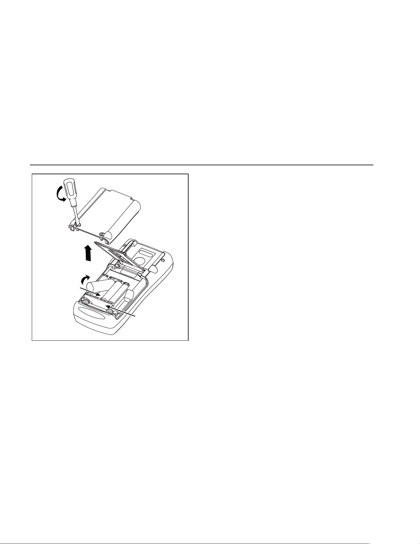
725
Users Manual
50
Battery and
Compartment
Fuse
Compartment
sh38f.eps
Figure 23. Replacing the Battteries
Maintenance
Cleaning the Calibrator
W Warning
To avoid personal injury or damage to the
calibrator, use only the specified
replacement parts and do not allow water
into the case.
Caution
To avoid damaging the plastic lens and case,
do not use solvents or abrasive cleansers.
Clean the calibrator and pressure modules with a soft
cloth dampened with water or water and mild soap.
Service Center Calibration or Repair
Calibration, repairs, or servicing not covered in this
manual should be performed only by qualified service
personnel. If the calibrator fails, check the batteries first,
and replace them if needed.
Verify that the calibrator is being operated in accordance
with the instructions in this manual. If the calibrator is
faulty, send a description of the failure with the calibrator.
Pressure modules do not need to accompany the
calibrator unless the module is faulty also. Be sure to
1.888.610.7664 sales@GlobalTestSupply.com
Fluke-Direct.com
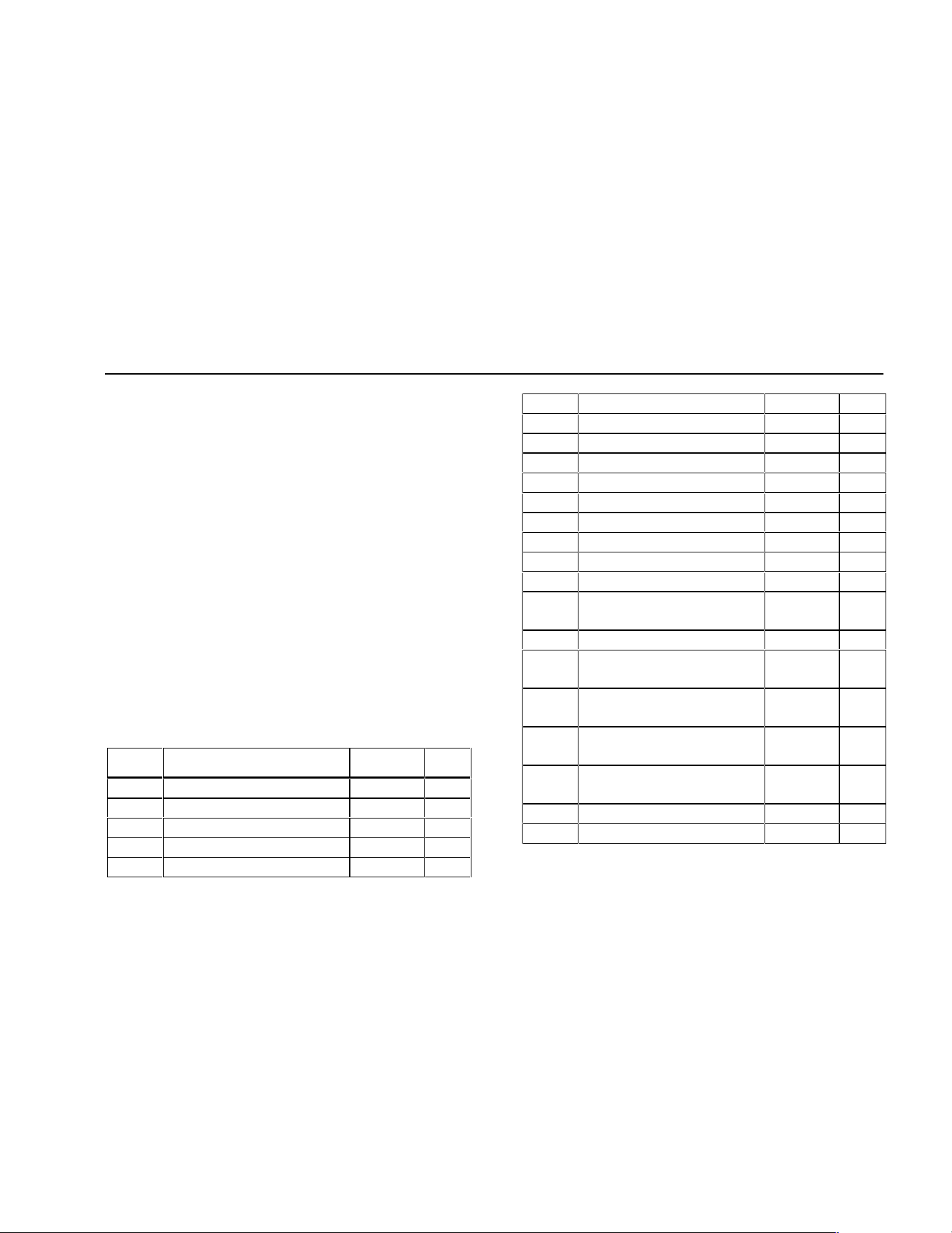
Maintenance
51
pack the calibrator securely, using the original shipping
container if it is available. Send the equipment postage
paid and insured, to the nearest Service Center. Fluke
assumes no responsibility for damage in transit.
The Fluke 725 calibrator covered by the warranty will be
promptly repaired or replaced (at Fluke’s option) and
returned to you at no charge. See the back of the title
page for warranty terms. If the warranty period has
expired, the calibrator will be repaired and returned for a
fixed fee. If the calibrator or pressure module is not
covered under the warranty terms, contact an authorized
service center for a price quote for repair.
To locate an authorized service center, refer to
“Contacting Fluke” at the beginning of the manual.
Replacement Parts
Table 9 lists the part number of each replaceable part.
Refer to Figure 24.
Table 9. Replacement Parts
Item Description PN Qty.
1 Case top 664232 1
2 LCD mask 664273 1
3 Elastomeric strips 802063 2
4 Input/output bracket 691391 1
5 LCD bracket 667287 1
6 Mounting screws 494641 11
7 Backlight 690336 1
8 LCD 690963 1
9 Keypad 690955 1
10 Case bottom 664235 1
11 AA alkaline batteries 376756 4
12 Case screws 832246 4
13 Battery door 664250 1
14 Accessory mount 658424 1
15 Tilt stand 659026 1
16 Battery door 1/4-turn
fasteners
948609 2
17 TL75 series test leads 855742 1
18 Test lead, red
Test lead, black
688051
688066
1
1
19 725 Product Overview
Manual
1549644 1
20 AC72 alligator clip, red
AC72 alligator clip, black
1670641
1670652
1
1
21 CD ROM, contains User
Manual
1549615 1
22 Input Decal 690948 1
23 Fuse 0.05A/250V 2002234 2
1.888.610.7664 sales@GlobalTestSupply.com
Fluke-Direct.com
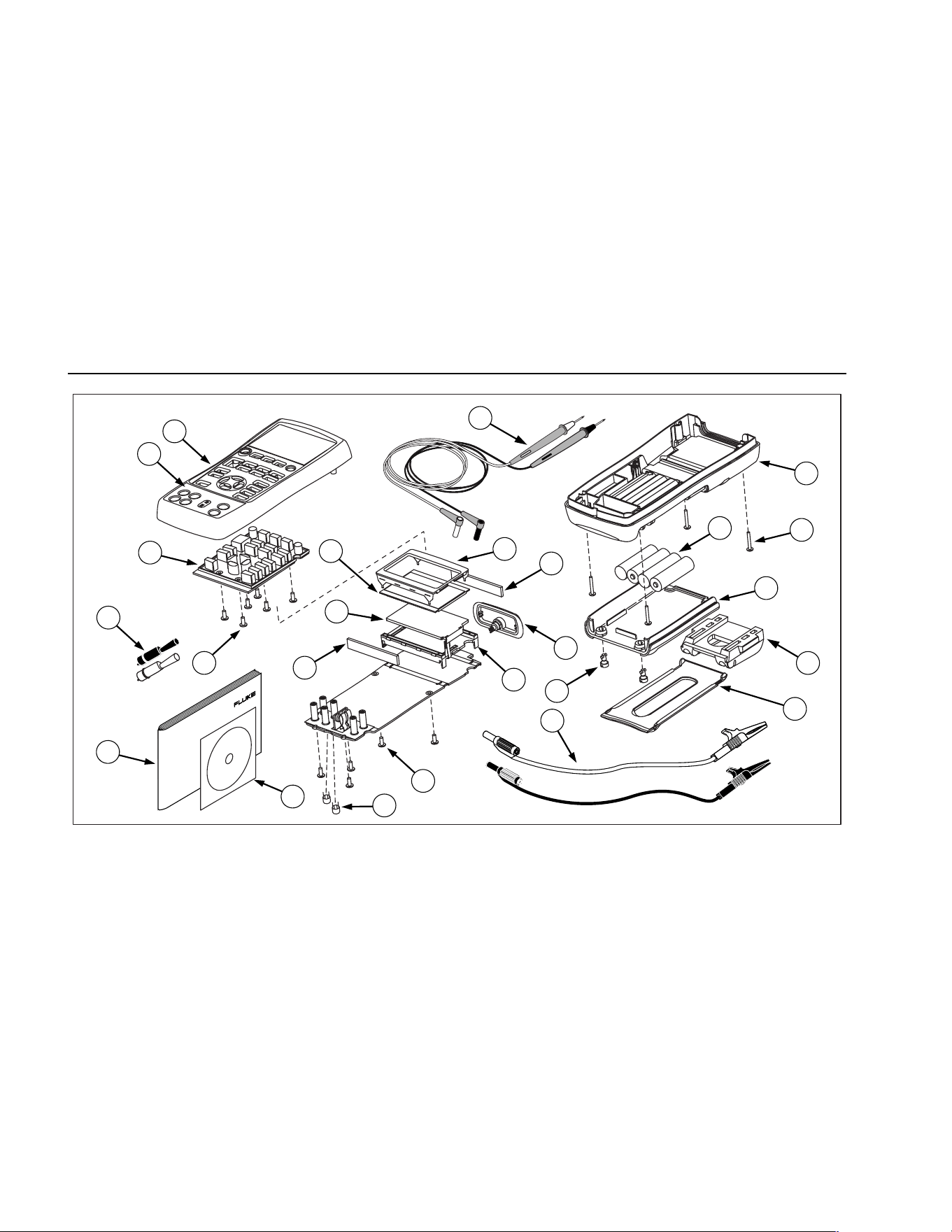
725
Users Manual
52
1
8
6
6
9
19
10
12
13
2
18
20
17
3
4
5
3
7
16
11
14
15
21
23
22
zi45f.eps
Figure 24. Replacement Parts
1.888.610.7664 sales@GlobalTestSupply.com
Fluke-Direct.com
Accessories
53
Accessories
For more information about these accessories and their
prices, contact your Fluke representative. Pressure
Modules and Fluke model numbers (see Table 10) are
listed below. (Differential models also operate in gage
mode.) Contact your Fluke representative about new
pressure modules not listed here.
• 700HTP 0 to 10,000 PSI Pump
• 700PTP -11.6 to 360 PSI Pump
• 700TC1 and 700TC2 Thermocouple Mini-plug Kits
External Fluke Pressure Module Compatibility
The output of Fluke 700P pressure modules can cause
the 725’s 5 digit display to overflow, or else produce
values that are too low to be read if inappropriate units
are selected. This is prevented by displaying OL on the
display per the following table.
Table 10. Fluke Pressure Module Compatibility
Pressure Unit Module Compatibility
Psi Available on all pressure ranges
In. H
2
0 All ranges through 3000 psi
cm. H
2
0 All ranges through 1000 psi
Bar 15 psi and above
Mbar All ranges through 1000 psi
KPa Available on all pressure ranges
In.Hg. Available on all pressure ranges
mm. Hg All ranges through 1000 psi
Kg/cm
2
15 psi and above
1.888.610.7664 sales@GlobalTestSupply.com
Fluke-Direct.com
725
Users Manual
54
Table 11. Pressure Modules
Fluke Model Number Range Type and Media
Fluke-700P00 0 to 1” H
2
O differential, dry
Fluke-700P01 0 to 10” H
2
O differential, dry
Fluke-700P02 0 to 1 psi differential, dry
Fluke-700P22 0 to 1 psi differential, wet
Fluke-700P03 0 to 5 psi differential, dry
Fluke-700P23 0 to 5 psi differential, wet
Fluke-700P04 0 to 15 psi differential, dry
Fluke-700P24 0 to 15 psi differential, wet
Fluke-700P05 0 to 30 psi gage, wet
Fluke-700P06 0 to 100 psi gage, wet
Fluke-700P27 0 to 300 psi gage, wet
Fluke-700P07 0 to 500 psi gage, wet
Fluke-700P08 0 to 1,000 psi gage, wet
Fluke-700P09 0 to 1,500 psi gage, wet
1.888.610.7664 sales@GlobalTestSupply.com
Fluke-Direct.com
Accessories
55
Table 11. Pressure Modules (cont.)
Fluke Model Number Range Type and Media
Fluke-700P29 0 to 3,000 psi gage, wet
Fluke-700P30 0 to 5,000 psi gage, wet
Fluke-700P31 0 to 10,000 psi gage, wet
Fluke-700PA3 0 to 5 psi absolute, wet
Fluke-700PA4 0 to 15 psi absolute, wet
Fluke-700PA5 0 to 30 psi absolute, wet
Fluke-700PA6 0 to 100 psi absolute, wet
Fluke-700PV3 0 to -5 psi vacuum, dry
Fluke-700PV4 0 to -15 psi vacuum, dry
Fluke-700PD2 ±1 psi dual range, dry
Fluke-700PD3 ±5 psi dual range, dry
Fluke-700PD4 ±15 psi dual range, dry
Fluke-700PD5 −15/+30 psi dual range, wet
Fluke-700PD6 −15/+100 psi dual range, wet
Fluke-700PD7 −15/+200 psi dual range, wet
1.888.610.7664 sales@GlobalTestSupply.com
Fluke-Direct.com
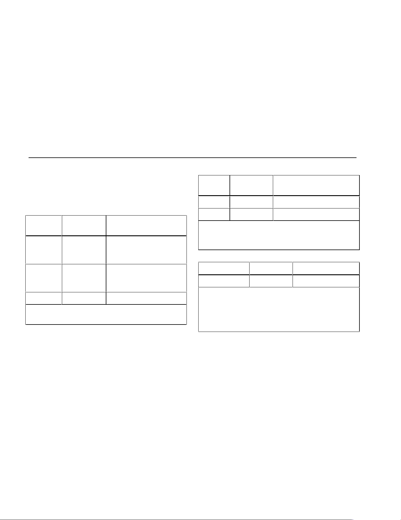
725
Users Manual
56
Specifications
Specifications are based on a one year calibration cycle
and apply from +18 °C to +28 °C unless stated otherwise.
All specifications assume a 5 minute warmup period.
DC Voltage Measurement
Range Resolution
Accuracy,
(% of Reading + Counts)
30 V
(upper
display)
0.001 V 0.02 % + 2
20 V
(lower
display)
0.001 V 0.02 % + 2
90 mV 0.01 mV 0.02 % + 2
Temperature coefficient -10 °C to 18 °C, +28 °C to
55 °C: ±0.005 % of range per °C
DC Voltage Source
Range Resolution
Accuracy,
(% of Reading + Counts)
100 mV 0.01 mV 0.02 % + 2
10 V 0.001 V 0.02 % + 2
Temperature coefficient -10 °C to 18 °C, +28 °C to
55 °C: ±0.005 % of range per °C
Maximum load: 1 mA
Millivolt Measurement and Source*
Range Resolution Accuracy
-10 mV to 75 mV 0.01 mV ±(0.025 % + 1 count)
Maximum input voltage: 30 V
Temperature coefficient -10 °C to 18 °C, +28 °C to
55 °C: ±0.005 % of range per °C
*Select this function by pressing T. The signal is
available at the thermocouple miniplug connector.
1.888.610.7664 sales@GlobalTestSupply.com
Fluke-Direct.com
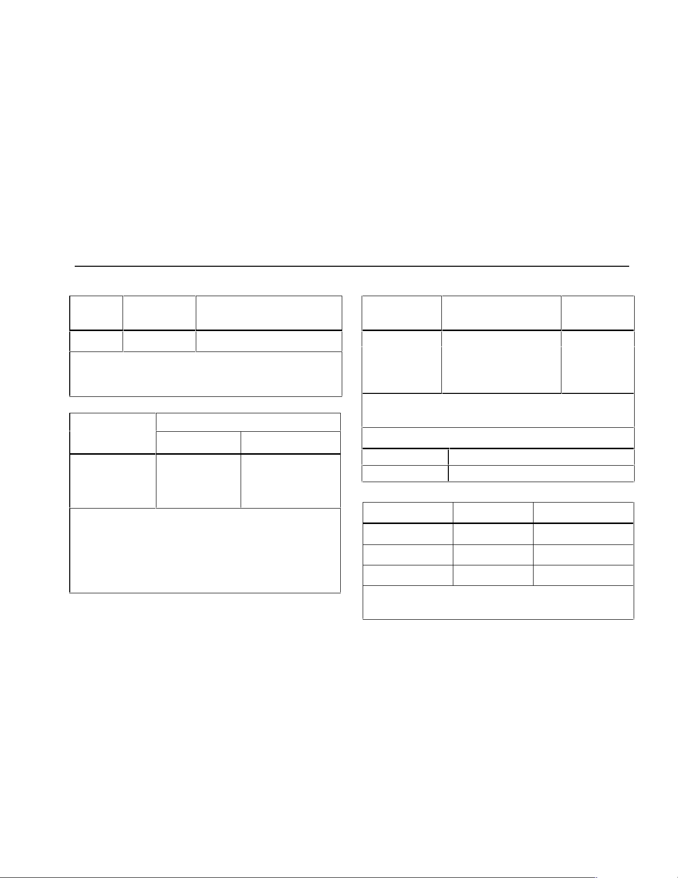
Specifications
57
DC mA Measurement and Source
Range Resolution
Accuracy,
(% of Reading + Counts)
24 mA 0.001 mA
0.02 % + 2
Temperature coefficient -10 °C to 18 °C, +28 °C to
55 °C: ±0.005 % of range per °C
Drive capability: 1000 Ω at 20 mA
Ohms Measurement
Accuracy ± Ω*
Ohms Range
4-Wire 2- and 3-Wire
0 to 400 Ω 0.1 0.15
400 to 1.5 kΩ 0.5 1.0
1.5 to 3.2 kΩ 11.5
Temperature coefficient -10 °C to 18 °C, +28 °C to
55 °C: ±0.005 % of range per °C
Excitation Current: 0.2 mA
Maximum input voltage: 30 V
* 2-wire: Does not include lead resistance.
3-wire: Assumes matched leads with a total resistance
not exceeding 100 Ω.
Ohms Source
Ohms Range
Excitation Current from
Measurement Device
Accuracy
± Ω
15 to 400 Ω 0.15 to 0.5 mA 0.15
15 to 400 Ω 0.5 to 2 mA 0.1
400 to 1.5 kΩ 0.05 to 0.8 mA 0.5
1.5 to 3.2 kΩ 0.05 to 0.4 mA 1
Temperature coefficient -10 °C to 18 °C, +28 °C to
55 °C: ± 0.005 % of resistance range per °C
Resolution
15 to 400 Ω 0.1 Ω
400 to 3.2 kΩ 1 Ω
Frequency Measurement
Range Resolution Accuracy
2.0 to 1000.0 CPM 0.1 CPM ± (0.05 % + 1 count)
1 to 1000 Hz 0.1 Hz ± (0.05 % + 1 count)
1.0 to 10.0 kHz 0.01 kHz ± (0.05 % + 1 count)
Sensitivity: 1V peak-to-peak minimum
Waveform: squarewave
1.888.610.7664 sales@GlobalTestSupply.com
Fluke-Direct.com
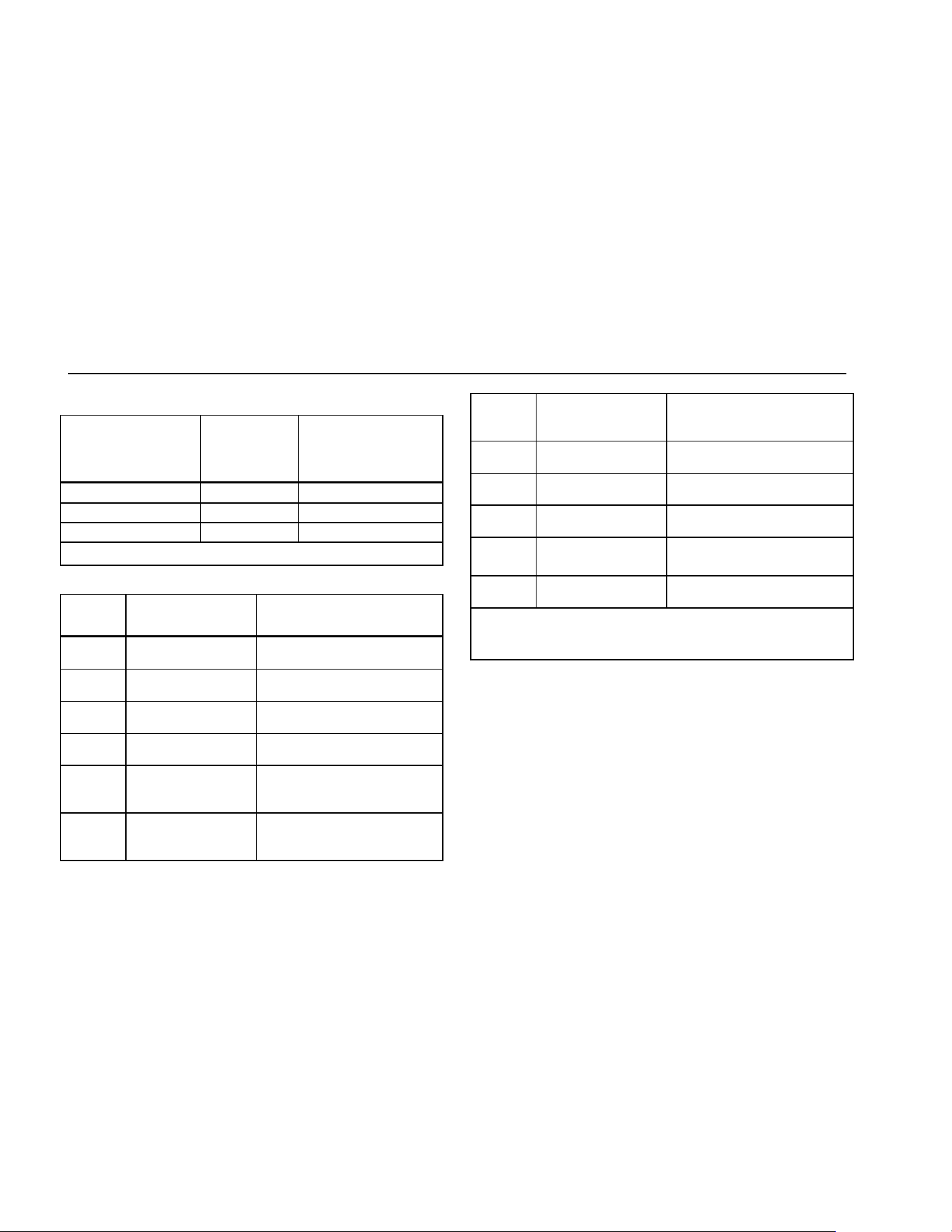
725
Users Manual
58
Frequency Source
Range
Resolution
Accuracy
(% of output
frequency)
2.0 to 1000.0 CPM 0.1 CPM ± 0.05 %
1 to 1000 Hz 1 Hz ± 0.05 %
1.0 to 10.0 kHz 0.1 kHz ± 0.25 %
Waveform: 5 V p-p squarewave, -0.1 V offset
Temperature, Thermocouples
Type
Range
Measure and Source
Accuracies (ITS-90)
J -200 to 0 °C
0 to 1200 °C
1.0 °C
0.7 °C
K -200 to 0 °C
0 to 1370 °C
1.2 °C
0.8 °C
T -200 to 0 °C
0 to 400 °C
1.2 °C
0.8 °C
E -200 to 0 °C
0 to 950 °C
0.9 °C
0.7 °C
R -20 to 0 °C
0 to 500 °C
500 to 1750 °C
2.5 °C
1.8 °C
1.4 °C
S -20 to 0 °C
0 to 500 °C
500 to 1750 °C
2.5 °C
1.8 °C
1.5 °C
B 600 to 800 °C
800 to 1000 °C
1000 to 1800 °C
2.2 °C
1.8 °C
1.4 °C
L -200 to 0 °C
0 to 900 °C
0.85 °C
0.7 °C
U -200 to 0 °C
0 to 400 °C
1.1 °C
0.75 °C
N -200 to 0 °C
0 to 1300 °C
1.5 °C
0.9 °C
XK -200 to -100 °C
-100 to 800 °C
0.5 °C
0.6 °C
BP 0 to 800 °C
800 to 2500 °C
1.2 °C
2.5 °C
Resolution:
J, K, T, E, L, N, U, XK, BP: 0.1 °C, 0.1 °F
B, R, S: 1 °C, 1 °F
1.888.610.7664 sales@GlobalTestSupply.com
Fluke-Direct.com
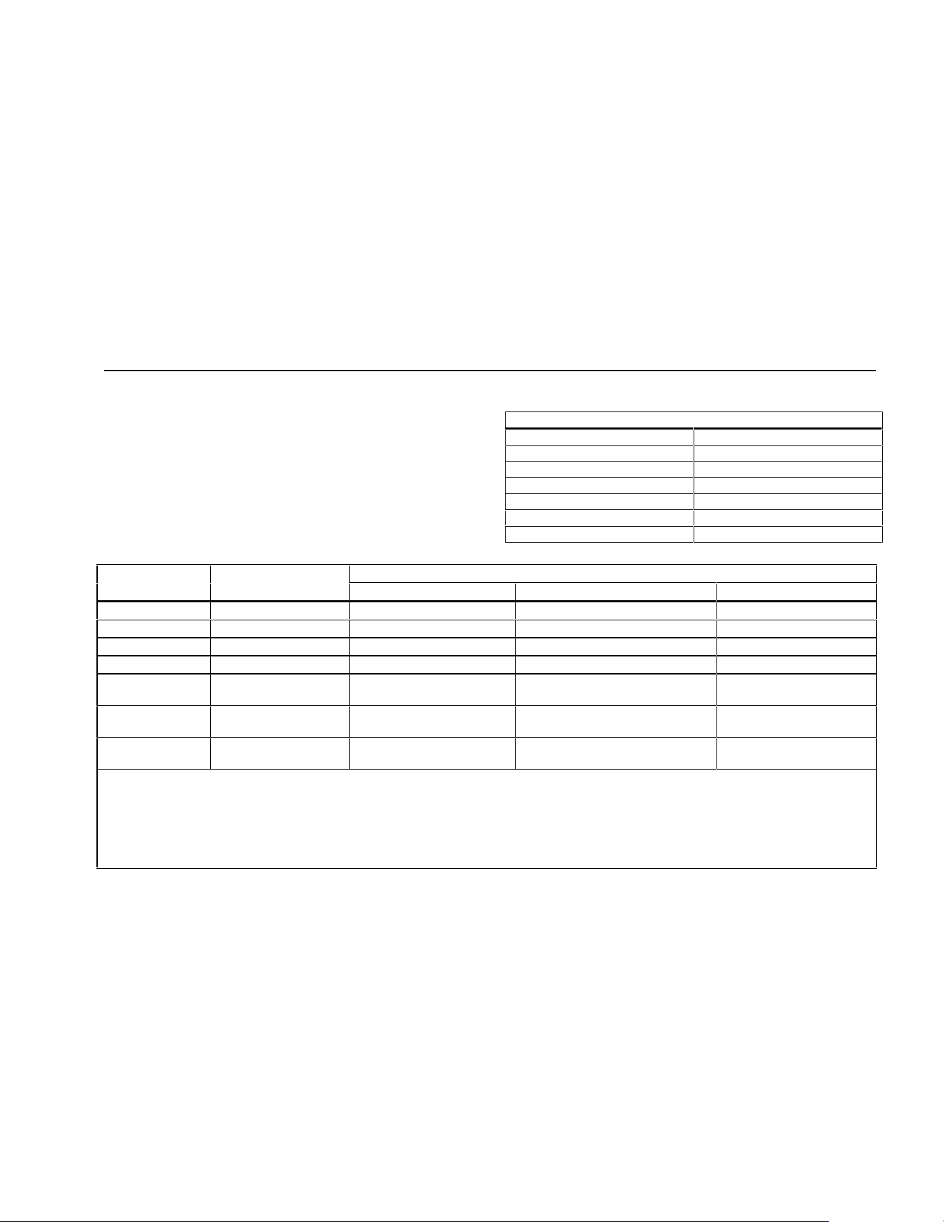
Specifications
59
Loop Power Supply
Voltage: 24 V
Maximum current: 22 mA
Short circuit protected
RTD Excitation (simulation)
Allowable Excitation by RTD type
Ni 120 0.15 to 3.0 mA
Pt 100-385 0.15 to 3.0 mA
Pt 100-392 0.15 to 3.0 mA
Pt 100-JIS 0.15 to 3.0 mA
Pt 200-385 0.15 to 3.0 mA
Pt 500-385 0.05 to 0.80 mA
Pt 1000-385 0.05 to 0.40 mA
Temperature, RTD Ranges, and Accuracies (ITS-90)
Accuracy
Type Range °C Measure 4-Wire °C Measure 2- and 3-Wire* °C Source °C
Ni120 -80 to 260 0.2 0.3 0.2
Pt100-385 - 200 to 800 0.33 0.5 0.33
Pt100-392 -200 to 630 0.3 0.5 0.3
Pt100-JIS -200 to 630 0.3 0.5 0.3
Pt200-385 -200 to 250
250 to 630
0.2
0.8
0.3
1.6
0.2
0.8
Pt500-385 -200 to 500
500 to 630
0.3
0.4
0.6
0.9
0.3
0.4
Pt1000-385 -200 to 100
100 to 630
0.2
0.2
0.4
0.5
0.2
0.2
Resolution: 0.1 °C, 0.1 °F
Allowable excitation current (source): Ni120, Pt100-385, Pt100-392, Pt100-JIS, Pt200-385: 0.15 to 3.0 mA
Pt500-385: 0.05 to 0.80 mA; Pt1000-385: 0.05 to 0.40 mA
RTD Source: Addresses pulsed transmitters and PLCs with pulses as short as 5 ms.
* 2-wire: Does not include lead resistance.
3-wire: Assumes matched leads with a total resistance not exceeding 100 Ω.
1.888.610.7664 sales@GlobalTestSupply.com
Fluke-Direct.com
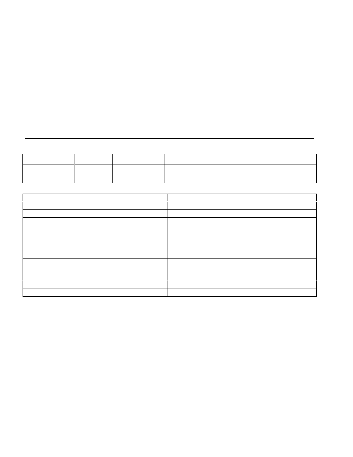
725
Users Manual
60
Pressure Measurement
Range Resolution Accuracy Units
Determined by
pressure module
5 digits Determined by
pressure module
psi, inH
2
O@4 °C, inH
2
O@20 °C, kPa, cmH
2
O@4 °C,
cmH
2
O@20 °C, bar, mbar, kg/cm
2
, mmHg, inHg
General Specifications
Operating temperature -10 °C to 55 °C
Storage temperature - 20 °C to 71 °C
Operating altitude 3000 meters above mean sea level
Relative Humidity (% RH operating without condensation) 90 % (10 to 30 °C)
75 % (30 to 40 °C)
45 % (40 to 50 °C)
35 % (50 to 55 °C)
uncontrolled < 10 °C
Vibration Random, 2 g, 5 to 500 Hz
Safety EN 61010-1:1993, ANSI/ISA S82.01-1994; CAN/CSA C22.2
No 1010.1:1992
Power requirements 4 AA alkaline batteries
Size 96 x 200 x 47 mm. (3.75 x 7.9 x 1.86 in)
Weight 650 gm (1 lb, 7 oz)
1.888.610.7664 sales@GlobalTestSupply.com
Fluke-Direct.com

61
Index
—0—
0% output parameter, setting, 36
—1—
100% output parameter, setting, 36
—4—
4 to 20 mA transmitter
simulating, 28
—A—
Accessories, 52
Auto ramping output, 37
—B—
Battery, replacing, 48
—C—
Calibration, 49
Cleaning calibrator, 49
Connections
for pressure measurement, 25
for pressure sourcing, 35
—D—
Display, 13
—E—
Electrical parameters
measurement, 18
sourcing, 28
—G—
Getting started, 14
—I—
I/P device, calibrating, 42
Input terminals, 8
Input/output terminals and connectors
(table), 9
1.888.610.7664 sales@GlobalTestSupply.com
Fluke-Direct.com

725
Users Manual
62
—K—
Key functions (table), 11
Keys, 10
—L—
Loop power
simulating, 28
supplying, 16
—M—
Measure functions, summary (table), 2
Measure mode, 16
Measuring
pressure, 25
temperature with RTDs, 22
temperature with thermocouples, 19
—O—
Output device, testing, 44
Output terminals, 8
—P—
Parts list, 50
Pressure modules available, 52
Pressure modules, zeroing, 26
Pressure transmitter, calibrating, 40
—R—
Recalling setups, 37
Remote control commands, 45
Repair, 49
RTD
simulating, 31
RTD
measuring, 22
types, 22
—S—
Safety information, 3
Servicing, 49
Setup
recalling, 37
storing, 37
Thermocouple, 31
Simulating
loop power, 28
RTD, 31
thermocouples, 31
Source functions, summary (table), 2
Source mode, 28
Sourcing
4 to 20 mA, 28
electrical parameters, 28
pressure, 34
thermocouples, 31
Specifications, 55
Standard equipment, 3
Stepping output, 36
Storing setups, 37
—T—
Temperature
measuring with RTD, 22
measuring with thermocouple, 19
Terminals
input, 8
output, 8
Thermocouple
measuring, 19
measuring temperature, 19
sourcing, 31
types, 19
Transmitter
4 to 20 mA, simulating, 28
Transmitter, calibrating, 38
—Z—
Zeroing pressure modules, 26
1.888.610.7664 sales@GlobalTestSupply.com
Fluke-Direct.com

9100S
Dry-Well Calibrator
Users Guide
9100S___ugeng0000
1.888.610.7664 sales@GlobalTestSupply.com
Fluke-Direct.com

Limited Warranty & Limitation of Liability
Each product from Fluke Corporation, (“Fluke”) is warranted to be free from defects in material and
workmanship under normal use and service. The warranty period is one year for Dry-Well Calibrators. The
warranty period begins on the date of the shipment. Parts, product repairs, and services are warranted for 90
days. The warranty extends only to the original buyer or end-user customer of a Fluke authorized reseller,
and does not apply to fuses, disposable batteries or to any other product, which in Fluke’s opinion, has been
misused, altered, neglected, or damaged by accident or abnormal conditions of operation or handling. Fluke
warrants that software will operate substantially in accordance with its functional specications for 90 days
and that it has been properly recorded on non-defective media. Fluke does not warrant that software will be
error free or operate without interruption. Fluke does not warrant calibrations on the Field Metrology Well.
Fluke authorized resellers shall extend this warranty on new and unused products to end-user customers
only but have no authority to extend a greater or different warranty on behalf of Fluke. Warranty support is
available if product is purchased through a Fluke authorized sales outlet or Buyer has paid the applicable
international price. Fluke reserves the right to invoice Buyer for importation costs of repairs/replacement
parts when product purchased in one country is submitted for repair in another country.
Fluke’s warranty obligation is limited, at Fluke’s option, to refund of the purchase price, free of charge
repair, or replacement of a defective product which is returned to a Fluke authorized service center within
the warranty period.
To obtain warranty service, contact your nearest Fluke authorized service center or send the product, with
a description of the difculty, postage, and insurance prepaid (FOB Destination), to the nearest Fluke
authorized service center. Fluke assumes no risk for damage in transit. Following warranty repair, the
product will be returned to Buyer, transportation prepaid (FOB Destination). If Fluke determines that the
failure was caused by misuse, alteration, accident or abnormal condition or operation or handling, Fluke will
provide an estimate or repair costs and obtain authorization before commencing the work. Following repair,
the product will be returned to the Buyer transportation prepaid and the Buyer will be billed for the repair
and return transportation charges (FOB Shipping Point).
THIS WARRANTY IS BUYER’S SOLE AND EXCLUSIVE REMEDY AND IS IN LIEU OF
ALL OTHER WARRANTIES, EXPRESS OR IMPLIED, INCLUDING BUT NOT LIMITED TO
ANY IMPLIED WARRANTY OF MERCHANTABILITY OR FITNESS FOR A PARTICULAR
PURPOSE. FLUKE SHALL NOT BE LIABLE FOR ANY SPECIAL, INDIRECT, INCIDENTAL. OR
CONSEQUENTIAL DAMAGES OR LOSSES, INCLUDING LOSS OF DATA, WHETHER ARISING
FROM BREACH OF WARRANTY OR BASED ON CONTRACT, TORT, RELIANCE OR ANY OTHER
THEORY.
Since some countries or states do not allow limitation of the term of an implied warranty, or exclusion
or limitation of incidental or consequential damages, the limitations and exclusions of this warranty may
not apply to every buyer. If any provision of this Warranty is held invalid or unenforceable by a court of
competent jurisdiction, such holding will not affect the validity or enforceability of any other provision.
Specifications subject to change without notice. • Copyright © 2005 • Printed in USA
1.888.610.7664 sales@GlobalTestSupply.com
Fluke-Direct.com

i
Table of Contents
1 Before You Start .......................................................................1
1.1 Introduction ............................................................................................... 1
1.2 Symbols Used ........................................................................................... 1
1.3 Safety Information ..................................................................................... 3
1.3.1 Warnings .........................................................................................................3
1.3.2 Cautions
..........................................................................................................4
1.4 Authorized Service Centers ...................................................................... 5
2 Specications and Environmental Conditions ......................9
2.1 Specifications ........................................................................................... 9
2.2 Environmental Conditions ......................................................................... 9
3 Quick Start .............................................................................. 11
3.1 Unpacking .............................................................................................. 11
3.2 Set-up ..................................................................................................... 11
3.3 Power ...................................................................................................... 11
3.4 Setting the Temperature .......................................................................... 11
4 Parts and Controls ................................................................13
4.1 Rear Panel .............................................................................................. 13
4.2 Side View ................................................................................................ 14
4.3 Front Panel .............................................................................................. 15
4.4 Constant Temperature Block Assembly .................................................. 15
5 General Operation ..................................................................17
5.1 Setting the Temperature .......................................................................... 17
5.2 Changing Display Units .......................................................................... 17
6 Controller Operation ..............................................................19
6.1 Well Temperature .................................................................................... 19
6.2 Temperature Set-point ............................................................................ 19
6.2.1 Programmable Set-points .............................................................................19
6.2.2 Set-point Value ..............................................................................................20
6.2.3 Temperature Scale Units ...............................................................................20
6.3 Scan ........................................................................................................ 20
1.888.610.7664 sales@GlobalTestSupply.com
Fluke-Direct.com

9100S Dry-Well Calibrator
ii
6.3.1 Scan Control ..................................................................................................22
6.3.2 Scan Rate ......................................................................................................22
6.4 Set-point Resistance ............................................................................... 22
6.5 Secondary Menu..................................................................................... 23
6.6 Heater Power .......................................................................................... 23
6.7 Proportional Band ................................................................................... 23
6.8 Controller Configuration .......................................................................... 24
6.9 Operating Parameters ............................................................................ 25
6.10 High Limit ................................................................................................ 25
6.11 Serial Interface Parameters .................................................................... 25
6.11.1 Baud Rate .....................................................................................................25
6.11.2 Sample Period ...............................................................................................26
6.11.3 Duplex Mode .................................................................................................26
6.11.4 Linefeed
........................................................................................................27
6.12 Calibration Parameters ........................................................................... 27
6.12.1 Hard Cutout ...................................................................................................28
6.12.2 R0
..................................................................................................................28
6.12.3 ALPHA
...........................................................................................................28
6.12.4 DELTA
............................................................................................................29
7 Digital Communication Interface ..........................................31
7.1 RS-232 Connection ................................................................................. 31
7.2 Interface Commands .............................................................................. 32
8 Test Probe Calibration ...........................................................35
8.1 Calibrating a Single Probe ...................................................................... 35
8.2 Dry-well Characteristics .......................................................................... 35
8.2.1 Stabilization and Accuracy ..........................................................................35
9 Calibration Procedure ............................................................37
9.1 Calibration Points .................................................................................... 37
9.2 Calibration Procedure ............................................................................. 37
9.2.1 Compute DELTA ............................................................................................38
9.2.2 Compute R0 and ALPHA ..............................................................................38
9.2.3 Accuracy and Repeatability ..........................................................................39
10 Maintenance ...........................................................................41
1.888.610.7664 sales@GlobalTestSupply.com
Fluke-Direct.com

iii
11 Troubleshooting .....................................................................43
11.1 Troubleshooting Problems, Possible Causes, and Solutions .................. 43
11.2 CE Comments ......................................................................................... 44
11.2.1 EMC Directive ...............................................................................................44
11.2.2 Low Voltage Directive (Safety) ......................................................................44
1.888.610.7664 sales@GlobalTestSupply.com
Fluke-Direct.com

9100S Dry-Well Calibrator
iv
Tables
Table 1International Electrical Symbols ............................................................ 1
Table 2Controller communications commands .............................................. 32
1.888.610.7664 sales@GlobalTestSupply.com
Fluke-Direct.com

v
Figures
Figure 1Back Panel ......................................................................................... 13
Figure 2Side view of the 9100S showing the prop stand ............................... 14
Figure 3Front panel ......................................................................................... 15
Figure 4Fixed block options ........................................................................... 16
Figure 5Controller operation flow chart .......................................................... 21
Figure 6Serial cable wiring ............................................................................. 31
1.888.610.7664 sales@GlobalTestSupply.com
Fluke-Direct.com

1
Before You Start
Symbols Used
1 Before You Start
1.1 Introduction
The Fluke 9100S Mid-Range Field Calibrator may be used as a portable instrument or
bench top temperature calibrator for calibrating thermocouple and RTD temperature
probes. This instrument is small enough to use in the eld, and accurate enough to use
in the lab. Calibrations may be done over a range of 35°C to 375°C (95°F to 707°F).
Temperature display and setability resolution is 0.1 degrees.
The instrument features:
●●
Rapid heating and cooling
●●
Prop stand
●●
RS-232 interface capability
Built in programmable features include:
●●
Temperature scan rate control
●●
Eight set-point memory
●●
Adjustable readout in °C or °F
The temperature is accurately controlled by Fluke’s digital controller. The controller
uses a precision platinum RTD as a sensor and controls the well temperature with a
triac driven heater.
The LED front panel continuously shows the current well temperature. The
temperature may be set, using the control buttons, to any desired temperature within
the instrument’s range. Multiple fault protection devices insure user and instrument
safety and protection.
This dry-well calibrator was designed for portability, low cost, and ease of operation.
Through proper use, the instrument will provide continuous accurate calibration
of temperature sensors and devices. The user should be familiar with the safety
guidelines and operating procedures of the calibrator as described in the instruction
manual.
1.2 Symbols Used
Table 1 lists the International Electrical Symbols. Some or all of these symbols may be
used on the instrument or in this manual.
Table 1 International Electrical Symbols
Symbol Description
AC (Alternating Current)
1.888.610.7664 sales@GlobalTestSupply.com
Fluke-Direct.com
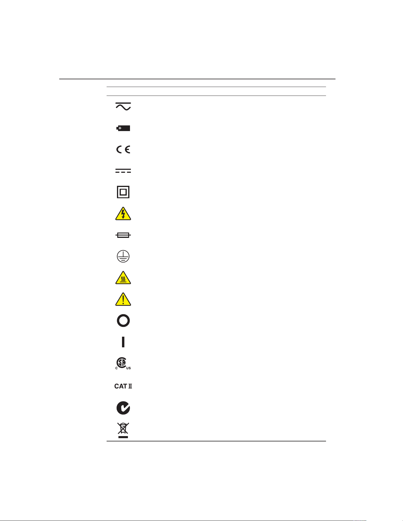
9100S Dry-Well Calibrator
Symbols Used
2
Symbol Description
AC-DC
Battery
Complies with European Union directives
DC
Double Insulated
Electric Shock
Fuse
PE Ground
Hot Surface (Burn Hazard)
Read the User’s Guide (Important Information)
Off
On
Canadian Standards Association
CAT II OVERVOLTAGE (Installation) CATEGORY II, Ploution Degree 2 per IEC1010-1
refers to the level of Impulsive Withstand Voltage protection provided. Equipment of
OVERVOLTAGE CATEGORY II is energy-consuming equipment to be supplied from the
xed installation. Examples include household, office, and laboratory appliances.
C-TICK Australian EMC mark
The European Waste Electrical and Electronic Equipment (WEEE) Directive (2002/96/
EC) mark.
1.888.610.7664 sales@GlobalTestSupply.com
Fluke-Direct.com

3
Before You Start
Safety Information
1.3 Safety Information
Use this instrument only as specied in this manual. Otherwise, the protection
provided by the instrument may be impaired. Refer to the safety information in the
Warnings and Cautions sections below.
The following denitions apply to the terms “Warning” and “Caution”.
●●
“Warning” identies conditions and actions that may pose hazards to the user.
●●
“Caution” identies conditions and actions that may damage the instrument
being used.
1.3.1 Warnings
To avoid personal injury, follow these guidelines.
GENERAL
●●
DO NOT use this instrument in environments other than those listed in the
User’s Guide.
●●
Inspect the instrument for damage before each use. DO NOT use the instrument
if it appears damaged or operates abnormally.
●●
Follow all safety guidelines listed in the user’s manual.
●●
Calibration Equipment should only be used by Trained Personnel.
●●
If this equipment is used in a manner not specied by the manufacturer, the
protection provided by the equipment may be impaired.
●●
Before initial use, or after transport, or after storage in humid or semi-humid
environments, or anytime the dry-well has not been energized for more than
10 days, the instrument needs to be energized for a “dry-out” period of 2 hours
before it can be assumed to meet all of the safety requirements of the IEC
1010-1. If the product is wet or has been in a wet environment, take necessary
measures to remove moisture prior to applying power such as storage in a low
humidity temperature chamber operating at 50 degree centigrade for 4 hours or
more.
●●
DO NOT use this instrument for any application other than calibration work.
The instrument was designed for temperature calibration. Any other use of the
instrument may cause unknown hazards to the user.
●●
Completely unattended operation is not recommended.
●●
Overhead clearance is required. DO NOT place the instrument under a cabinet
or other structure. Always leave enough clearance to allow for safe and easy
insertion and removal of probes.
●●
If the instrument is used in a manner not in accordance with the equipment
design, the operation of the dry-well may be impaired or safety hazards may
arise.
●●
This instrument is intended for indoor use only.
1.888.610.7664 sales@GlobalTestSupply.com
Fluke-Direct.com

9100S Dry-Well Calibrator
Safety Information
4
BURN HAZARDS
●●
DO NOT turn the instrument upside down with the inserts in place; the inserts
will fall out.
●●
DO NOT operate near ammable materials.
●●
Use of this instrument at HIGH TEMPERATURES for extended periods of
time requires caution.
●●
DO NOT touch the well access surface of the instrument.
●●
The block vent may be very hot due to the fan blowing across the heater block
of the dry-well.
●●
The temperature of the well access is the same as the actual display
temperature, e.g. if the instrument is set to 375°C and the display reads 375°C,
the well is at 375°C.
●●
For top loading dry-wells, the top sheet metal of the dry-well may exhibit
extreme temperatures for areas close to the well access.
●●
The air over the well can reach temperatures greater that 200°C for high
temperature (400°C and higher) dry-wells. Note: Probes and inserts may
be hot and should only be inserted and removed from the instrument when
the instrument is set at temperatures less than 50°C. Use extreme care when
removing hot inserts.
●●
DO NOT turn off the instrument at temperatures higher than 100°C. This could
create a hazardous situation. Select a set-point less than 100°C and allow the
instrument to cool before turning it off.
●●
The high temperatures present in dry-wells designed for operation at 300°C
and higher may result in res and severe burns if safety precautions are not
observed.
ELECTRICAL SHOCK
●●
DO NOT operate this instrument without a properly grounded, properly
polarized power cord. Electric shock may result.
●●
DO NOT connect this instrument to a non-grounded, non-polarized outlet.
Ensure the earth ground to the outlet is properly connected. Electrical shock
may result if the outlet is not installed correctly.
●●
Always replace the power cord with an approved cord of the correct rating and
type.
●●
HIGH VOLTAGE is used in the operation of this equipment. SEVERE
INJURY or DEATH may result if personnel fail to observe safety precautions.
Before working inside the equipment, turn power off and disconnect power
cord.
●●
If supplied with user accessible fuses, always replace the fuse with one of the
same rating, voltage and type.
1.3.2 Cautions
●●
Always operate this instrument at room temperature between 41°F and 122°F
(5°C to 50°C). Allow sufcient air circulation by leaving at least 6 inches (15
1.888.610.7664 sales@GlobalTestSupply.com
Fluke-Direct.com

5
Before You Start
Authorized Service Centers
cm) of clearance around the instrument.
●●
Component lifetime can be shortened by continuous high temperature
operation.
●●
DO NOT use uids to clean out the well.
●●
Never introduce any foreign material into the probe hole of the insert. Fluids,
etc. can leak into the instrument causing damage.
●●
DO NOT change the values of the calibration constants from the factory set
values. The correct setting of these parameters is important to the safety and
proper operation of the calibrator.
●●
DO NOT drop the probe sheath in to the well. This type of action can cause a
shock to the sensor and affect the calibration.
●●
The instrument and any thermometer probes used with it are sensitive
instruments that can be easily damaged. Always handle these devices with care.
DO NOT allow them to be dropped, struck, stressed, or overheated.
●●
The Factory Reset Sequence (see Section 11, Troubleshooting, on page
43) should be performed only by authorized personnel if no other action is
successful in correcting a malfunction. You must have a copy of the most recent
Report of Calibration to restore the calibration parameters.
●●
DO NOT operate this instrument in an excessively wet, oily, dusty, or dirty
environment. Always keep the well and inserts clean and clear of foreign
material.
●●
The dry-well is a precision instrument. Although it has been designed for
optimum durability and trouble free operation, it must be handled with care.
Always carry the instrument in an upright position to prevent the probe sleeves
from dropping out.
●●
If a mains supply power uctuation occurs, immediately turn off the instrument.
Power bumps from brown-outs could damage the instrument. Wait until the
power has stabilized before re-energizing the instrument.
●●
The prop stand was not designed to be used as a handle for carrying the
instrument. To avoid damage, do not force the prop stand beyond the incline
positions of the instrument.
●●
Allow for probe expansion inside the well as the block heats.
●●
Most probes have handle temperature limits. Be sure that the probe handle
temperature limit is not exceeded in the air above the instrument.
1.4 Authorized Service Centers
Please contact one of the following authorized Service Centers to coordinate service
on your Fluke product:
1.888.610.7664 sales@GlobalTestSupply.com
Fluke-Direct.com
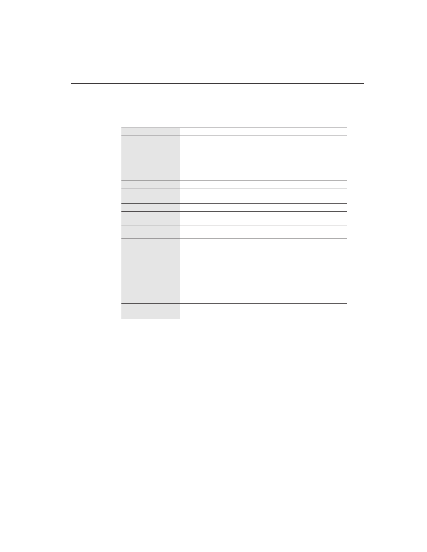
9
Specications and Environmental Conditions
Environmental Conditions
2 Specications and Environmental Conditions
2.1 Specications
Range 35°C to 375°C (95°F to 707°F)
Accuracy ±0.25°C at 50°C
±0.25°C at 100°C
±0.5°C at 375°C
Stability ±0.07°C at 50°C
±0.1°C at 100°C
±0.3°C at 375°C
Resolution 0.1°C or °F
Well-to-Well Uniformity ±0.2°C with sensors of similar size at equal depths within wells
Heating Times 35 to 375°C: 9.5 minutes
Stabilization 5 minutes
Cooling Times 375 to 100°C: 14 minutes
Well Depth 4 inches (102 mm)
1/16 inch (1.6 mm) hole is 3.5 inches (89 mm) deep
Fixed Block Options See Section , Constant Temperature Block Assembly, on page and Figure
on page
Power 115 VAC (±10%), 55–65 Hz, 1.5 A or 230 VAC (±10%), 0.8 A, 45–55 Hz, 175
W
Size 2.25” H x 4.9” W x 6.1”D
(57mm x 125mm x 150 mm)
Weight 2 lb. 3 oz. (1.08 Kg)
Safety Conforms to EN61010-1
Conforms to CAN/CSA C22.2 No.1010.1
UL3111 and ANSI/ISA-S82.01
OVERVOLTAGE (Installation) CATEGORY II, Ploution Degree 2 per
IEC1010-1
Fault Protection Sensor burnout protection, over-temperature cutout, and electrical fuses
Fuse Rating 250 V 3 A FF (very fast acting) NO USER SERVICEABLE PARTS
2.2 Environmental Conditions
Although the instrument has been designed for optimum durability and trouble-free
operation, it must be handled with care. The instrument should not be operated in an
excessively dusty or dirty environment. Maintenance and cleaning recommendations
can be found in the Maintenance Section of this manual.
The instrument operates safely under the following conditions:
●●
temperature range: 5–50°C (41–122°F)
●●
ambient relative humidity: 15–50%
●●
pressure: 75kPa–106kPa
●●
mains voltage within ±10% of nominal
●●
vibrations in the calibration environment should be minimized
●●
altitudes less than 2000 meters
●●
indoor use only
1.888.610.7664 sales@GlobalTestSupply.com
Fluke-Direct.com

11
Quick Start
Setting the Temperature
3 Quick Start
3.1 Unpacking
Unpack the dry-well carefully and inspect it for any damage that may have occurred
during shipment. If there is shipping damage, notify the carrier immediately.
Verify that the following components are present:
●●
9100S Dry-well
●●
Power Cord
●●
User’s Guide with Report of Calibration
●●
RS-232 Cable
●●
9930 Interface-it Software and User’s Guide
3.2 Set-up
Place the calibrator on a at surface with at least 6 inches of free space around the
instrument. Always leave enough clearance in front of the instrument to allow for
safe and easy insertion and removal of probes. The prop stand may be swung down to
raise the front of the instrument from a horizontal position. Plug the power cord into a
grounded mains outlet. Observe that the nominal voltage corresponds to that indicated
on the calibrator.
Turn on the power to the calibrator by toggling the power switch on. The fan should
begin quietly blowing air through the instrument and the controller display should
illuminate after 3 seconds. After a brief self-test the controller should begin normal
operation. If the unit fails to operate please check the power connection.
The display should show the well temperature and the well heater will bring the
temperature of the well to the set-point temperature.
After using the calibrator, allow the well to cool by setting the temperature to 25°C
and waiting 1/2 hour before turning the instrument off.
3.3 Power
Plug the instrument power cord into a mains outlet of the proper voltage, frequency,
and current capability. Refer to Section 3.1, Specications, for the power details. Turn
the instrument on using the switch on the rear panel. The instrument will turn on and
begin to heat to the previously programmed temperature set-point. The front panel
LED display will indicate the actual instrument temperature.
3.4 Setting the Temperature
Section explains in detail how to set the temperature set-point on the calibrator using
the front panel keys. The procedure is summarized here.
1. Press “SET” twice to access the set-point value.
2. Press u or d arrow to change the set-point value.
1.888.610.7664 sales@GlobalTestSupply.com
Fluke-Direct.com

3. Press “SET” to program in the new set-point.
4. Press and hold “EXIT” to return to the temperature display.
When the set-point temperature is changed the controller switches the well heater on or
off to raise or lower the temperature. The displayed well temperature gradually changes
until it reaches the set-point temperature. The well may require 5 to 10 minutes to reach
the set-point depending on the span. Another 5 to 10 minutes is required to stabilize
within ±0.1°C of the set-point. Ultimate stability may take 15 to 20 minutes more of
stabilization time.
1.888.610.7664 sales@GlobalTestSupply.com
Fluke-Direct.com
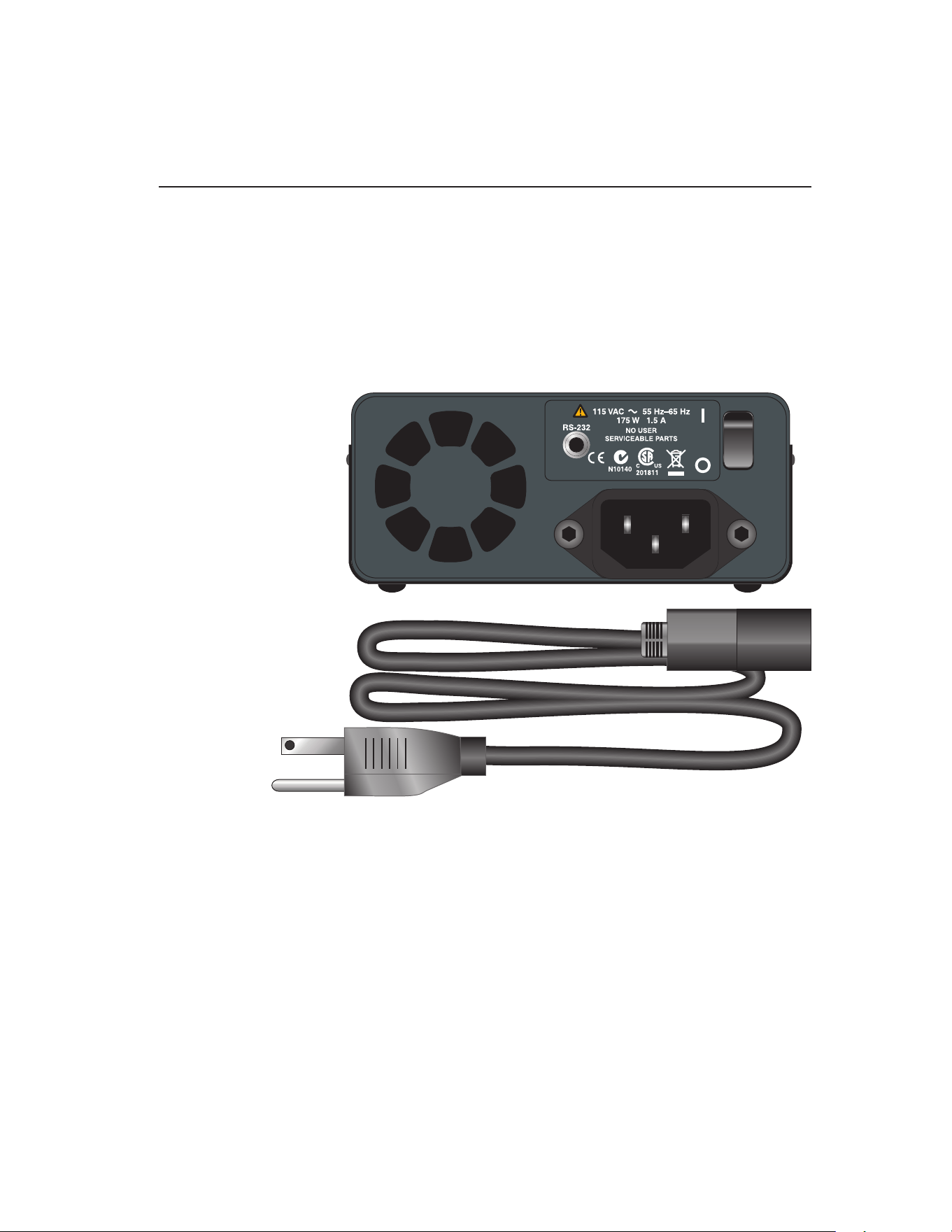
13
Parts and Controls
Rear Panel
4 Parts and Controls
The user should become familiar with the dry-well calibrator and its parts: (See
Figures 1, 2, and 3).
4.1 Rear Panel
Power Cord - The removable power cord, (Figure 1 on this page) attaches to the back
side of the instrument. It plugs into a standard 115 VAC (optional 230 VAC) grounded
socket.
Figure 1 Back Panel
Power Switch - The power switch is located on the back panel of the instrument. The
switch is either on or off. The on position is for normal operation. The off position
disconnects power to the entire unit.
Fan - The fan inside the instrument runs continuously when the unit is being operated
to provide cooling to the instrument. The fan has two speeds, a slow speed for control
operation and a faster speed for rapid cooling. Slots at the top and around the corners
of the instrument are provided for airow. The area around the calibrator must be kept
clear to allow adequate ventilation. The air is directed from the back to the front and
may be hot. Allow 6 inches of open space around the calibrator to allow adequate
ventilation.
1.888.610.7664 sales@GlobalTestSupply.com
Fluke-Direct.com
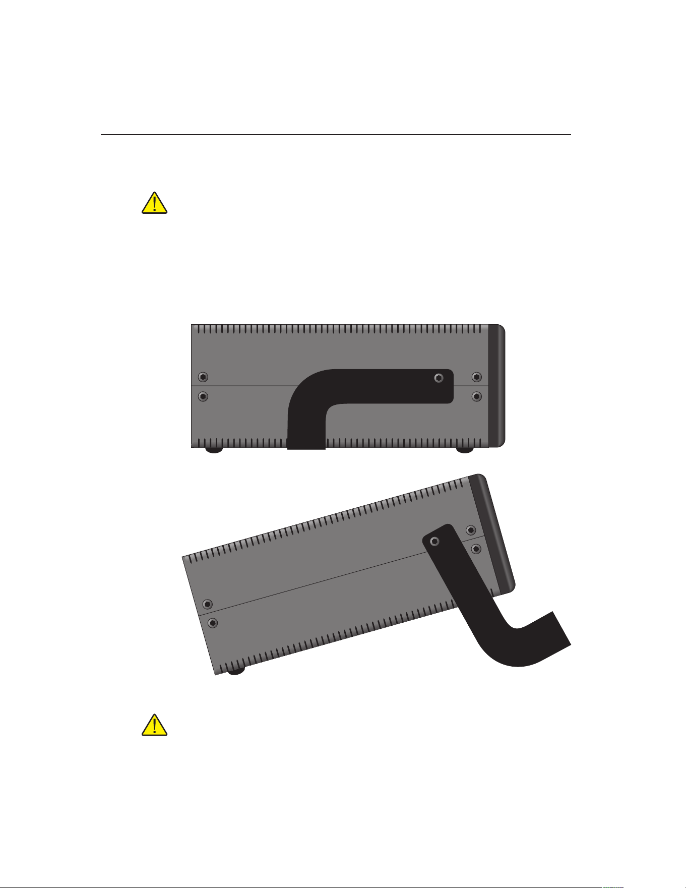
9100S Dry-Well Calibrator
Side View
14
RS-232 - The RS-232 serial port provides a means for connecting the instrument to a
computer or a printer using the included serial cable.
WARNING: Always leave enough clearance in front of the calibrator to allow
for safe and easy installation and removal of probes.
4.2 Side View
Prop Stand - The prop stand (Figure 2 on this page) is located on the bottom side of
the instrument and lays at against the bottom of the instrument when not in use. The
prop stand can be swung down into a standing position when using the instrument at
an inclined position.
Figure 2 Side view of the 9100S showing the prop stand
CAUTION: The prop stand was not designed to be used as a handle for carrying
the instrument. To avoid damage,do not force the prop stand beyond the inclined
position of the instrument.
1.888.610.7664 sales@GlobalTestSupply.com
Fluke-Direct.com
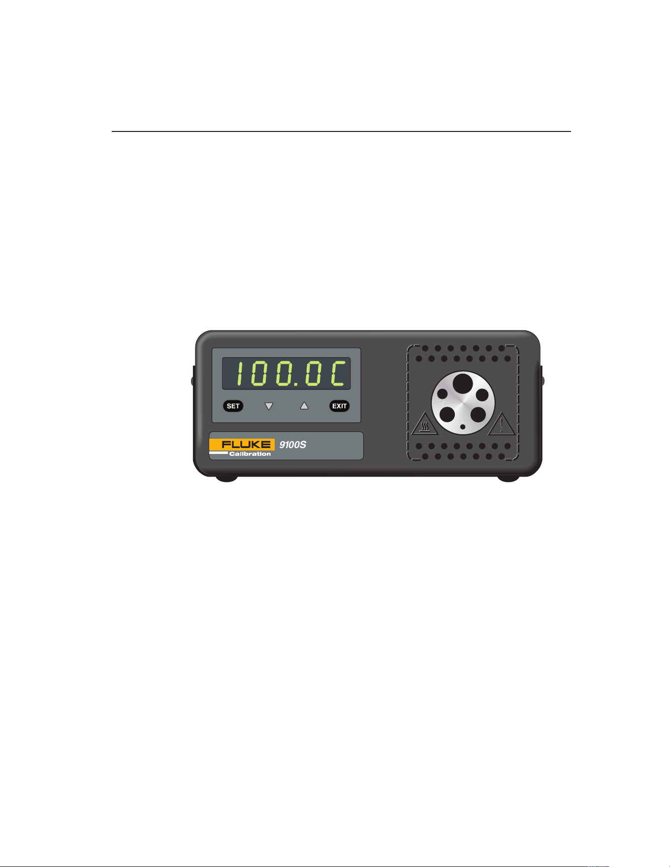
15
Parts and Controls
Constant Temperature Block Assembly
4.3 Front Panel
Well Block - Located on the right side of the front panel is the well opening where
a block (Figure ) designed to accept different probe sizes is installed. Each block is
designed to accept different diameter temperature sensors. Four different blocks are
available. See Section , Constant Temperature Block Assembly for details.
Controller Display - The digital display is an important part of the temperature
controller because it not only displays set and actual temperatures but also various
calibrator functions, settings, and constants. The display shows temperatures in units
according to the selected scale °C or °F.
Controller Keypad - The four button keypad allows easy setting of the set-point
temperature. The control buttons (SET, d, u, and EXIT) are used to set the
calibrator temperature set-point, access and set other operating parameters, and access
and set calibration parameters.
Figure 3 Front panel
Setting the control temperature is done directly in degrees of the current scale. It can
be set to one-tenth of a degree Celsius or Fahrenheit.
The functions of the buttons are as follows:
SET – Used to display the next parameter in the menu and to store parameters to the
displayed value.
d (down arrow) – Used to decrement the displayed value of parameters.
u (up arrow) – Used to increment the displayed value.
EXIT – Used to exit a function and to skip to the next function. Any changes made to
the displayed value are ignored.
4.4 Constant Temperature Block Assembly
The “Block” is made of aluminum and provides a relatively constant and accurate
temperature environment in which the sensor that is to be calibrated is inserted. A
high-temperature platinum RTD imbedded in the block assembly senses and controls
1.888.610.7664 sales@GlobalTestSupply.com
Fluke-Direct.com
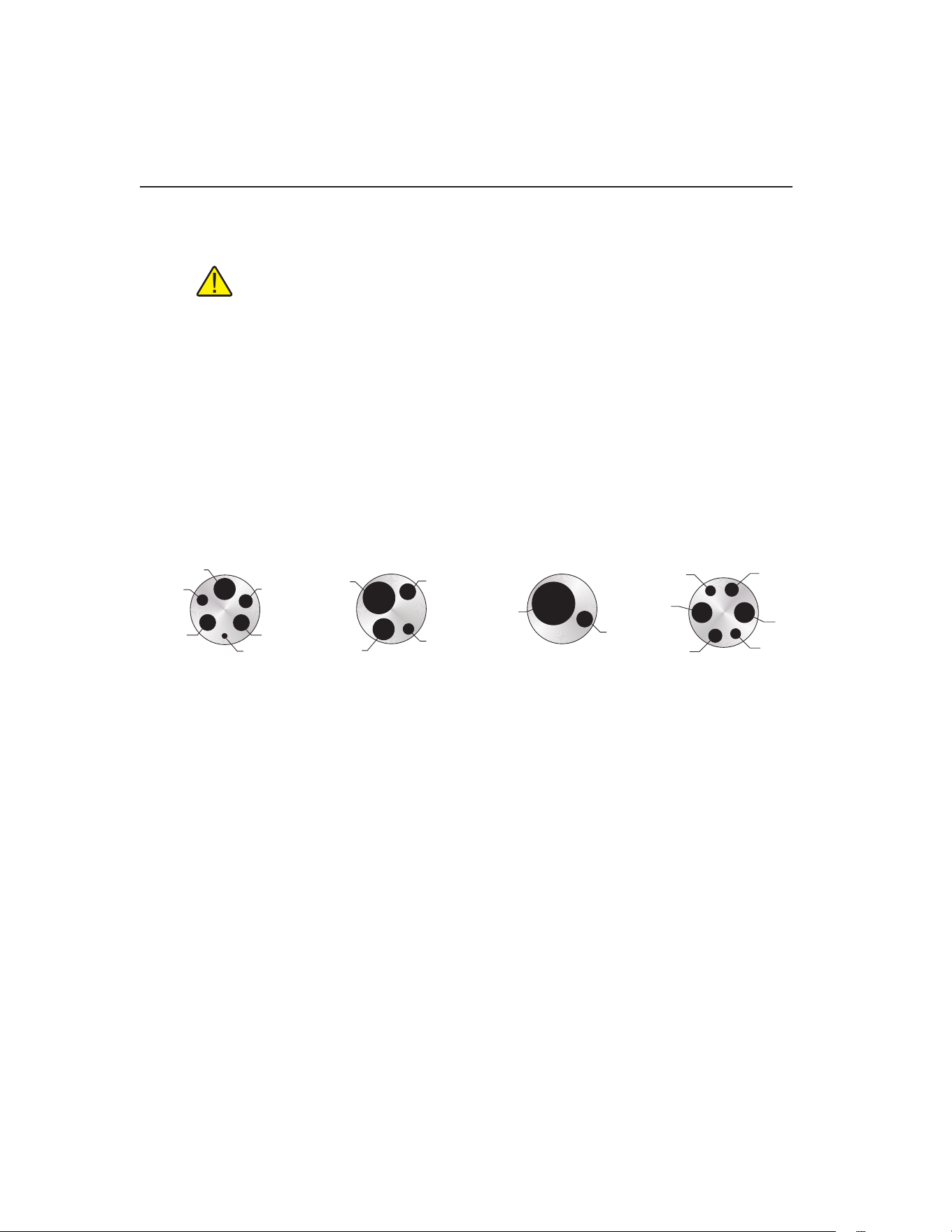
9100S Dry-Well Calibrator
Constant Temperature Block Assembly
16
the temperature of the block. The entire assembly is suspended in an air cooled
chamber thermally isolated from the chassis and electronics.
WARNING: The opening in front of the block may be very hot due to air
blowing forward.
The constant temperature block is available in the following congurations.
Block “A” has six holes, four that accept probe diameters of 1/4”, 5/32”, 1/8”, and
1/16”, and two that accept probes of 3/16” diameter to allow comparison calibrations.
Block “B” has four holes that accept probe diameters of 3/8”, 1/4”, 3/16” and 1/8”.
Block “C” has two holes that accept probe diameters of 3/16” and 1/2”.
Block “D” has six holes, two that accept probe diameter of 3 mm, two that accept
probes of 4 mm diameter, and two that accept probes of 6 mm diameter.
Surrounding the well opening are small ventilation holes which provide cooling to the
instrument.
Figure 4
1/16" (1.6 mm)
3/16" (4.8 mm) 3/16" (4.8 mm)
1/8" (3.2 mm)
5/32" (4 mm)
1/4" (6.4 mm)
Block “A”
9100S Fixed-Block Options
3/16" (4.8 mm)
1/8" (3.2 mm)
1/4" (6.4 mm)
3/8" (9.5 mm)
Block “B”
3/16" (4.8 mm)
1/2" (12.7 mm)
Block “C”
6 mm
Block “D”
4 mm
6 mm
3 mm
3 mm
4 mm
Fixed block options
1.888.610.7664 sales@GlobalTestSupply.com
Fluke-Direct.com

17
General Operation
Changing Display Units
5 General Operation
5.1 Setting the Temperature
Section explains in detail how to set the temperature set-point on the calibrator using
the front panel keys. The procedure is summarized here.
1. Press “SET” twice to access the set-point value.
2. Press u or d to change the set-point value.
3. Press “SET” to program in the new set-point.
4. Press and hold “EXIT” to return to the temperature display.
When the set-point temperature is changed the controller switches the well heater on
or off to raise or lower the temperature. The displayed well temperature gradually
changes until it reaches the set-point temperature. The well may require 5 to 10
minutes to reach the set-point depending on the span. Another 5 to 10 minutes is
required to stabilize within ±0.1°C of the set-point. Ultimate stability may take 15 to
20 minutes more of stabilization time.
5.2 Changing Display Units
This instrument can display temperature in Celsius or Fahrenheit. The temperature
units are shipped from the factory set to Celsius. There are two ways to change to
Fahrenheit or back to Celsius:
5. Press the “SET” and u simultaneously. The temperature display changes units.
or
6. Press the “SET” key three times from the temperature display to show
Un= C
7. Press the u or d key to change units.
8. Press “SET” to save the setting or “EXIT” to continue without changing the
setting.
1.888.610.7664 sales@GlobalTestSupply.com
Fluke-Direct.com

19
Controller Operation
Temperature Set-point
6 Controller Operation
This chapter discusses in detail how to operate the dry-well temperature controller
using the front control panel. Using the front panel key-switches and LED display the
user may monitor the well temperature, set the temperature set-point in degrees C or F,
monitor the heater output power, adjust the controller proportional band, and program
the calibration parameters, operating parameters, and serial interface conguration.
Operation of the functions and parameters are shown in the owchart in Figure 5 on
page 21 This chart may be copied for reference.
In the following discussion a button with the word SET or EXIT inside or u, and
d, indicates the panel button while the dotted box indicates the display reading.
Explanations of the button or display reading are to the right of each button or display
value.
6.1 Well Temperature
The digital LED display on the front panel allows direct viewing of the actual well
temperature. This temperature value is normally shown on the display. The units, C or
F, of the temperature value are displayed at the right. For example,
100.0 C WelltemperatureindegreesCelsius
The temperature display function may be accessed from any other function by pressing
and holding the “EXIT” button.
6.2 Temperature Set-point
The temperature set-point can be set to any value within the range and with resolution
as given in the specications. Be careful not to exceed the safe upper temperature limit
of any device inserted into the well.
Setting the temperature involves selecting the set-point memory and adjusting the set-
point value.
6.2.1 Programmable Set-points
The controller stores 8 set-point temperatures in memory. The set-points can be
quickly recalled to conveniently set the calibrator to a previously programmed
temperature set-point.
To set the temperature, rst select the set-point memory. This function is accessed
from the temperature display function by pressing “SET”. The number of the set-
point memory currently being used is shown at the left on the display followed by the
current set-point value.
100.0 C WelltemperatureindegreesCelsius
S
Accessset-pointmemory
1.888.610.7664 sales@GlobalTestSupply.com
Fluke-Direct.com

1 100. Set-pointmemory1location,100°Ccurrentlyused
To change to another set-point memory press the up or down arrow.
4 300. Newset-pointmemory4location,300°C
Press “SET” to accept the new selection and access the set-point value. Press “EXIT” to
continue and to ignore any changes.
S
Acceptselectedset-pointmemory
6.2.2 Set-point Value
The set-point value may be adjusted after selecting the set-point memory and pressing
“SET”.
4 200. Set-point4valuein°C
If the set-point value does not need to be changed, press and hold “EXIT” to resume
displaying the well temperature. To change the set-point value, press “SET” and then
press the up or down arrow.
220.0 Newset-pointvalue
When the desired set-point value is reached, press “SET” to accept the new value and
access the temperature scale units selection. If “EXIT” is pressed, any changes made to
the set-point are ignored.
S
Acceptnewset-pointvalue
6.2.3 Temperature Scale Units
The temperature scale units of the controller maybe set by the user to degrees Celsius
(°C) or Fahrenheit (°F). The units are used in displaying the well temperature, set-point,
proportional band, and high limit.
Press “SET” after adjusting the set-point value to change display units.
Un= C Scaleunitscurrentlyselected
Press the up or down arrow to change the units.
Un= F Newunitsselected
Press “SET” to accept the new units or “EXIT” to cancel.
Note: The temperature scale units may also be changed by pressing “SET” and u when
the temperature is displayed. This action toggles the units between °F and °C.
6.3 Scan
The scan rate can be set and enabled so that when the set-point is changed the dry-well
heats or cools at a specied rate (degrees per minute) until it reaches the new set-point.
With the scan disabled the dry-well heats or cools at the maximum possible rate.
1.888.610.7664 sales@GlobalTestSupply.com
Fluke-Direct.com
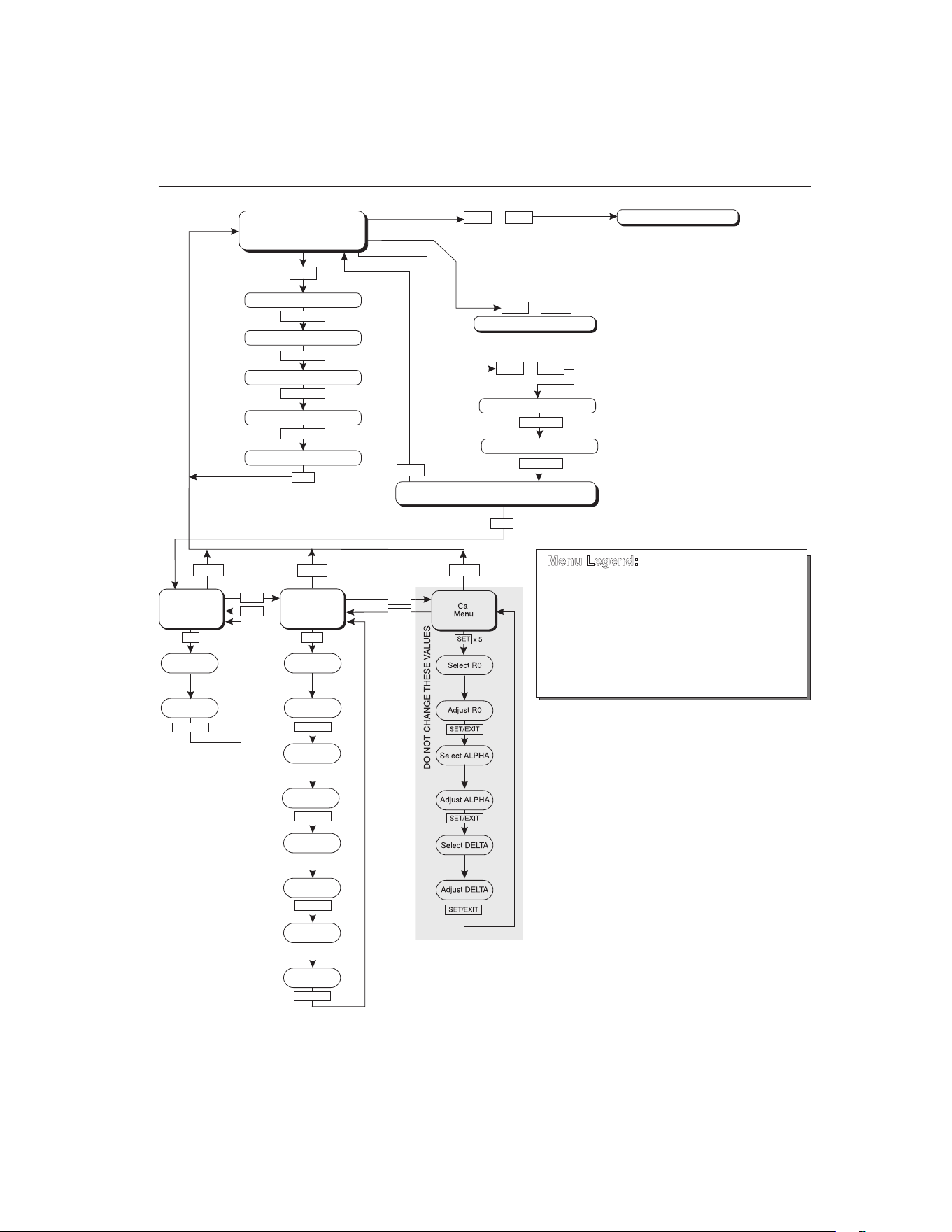
21
Controller Operation
Scan
Figure 5
UP
UP
DOWN
DOWN
SET
Operating
Parameters
Menu
SET
SET
SET/EXIT
SET/EXIT
SET/EXIT
Cal
Menu
SET/EXIT
SET/EXIT
Serial
Interface
Menu
BAUD
Rate
Adjust
BAUD Rate
Sample
Period
Adj. Sample
Period
Duplex
Mode
Adj. Duplex
Mode
Linefeed
Adjust
Linefeed
Select ALPHA
Adjust ALPHA
Select DELTA
Adjust DELTA
EXIT
EXIT
EXIT
EXIT
DOWN
SET
SET
SET
+
+
+
Display Power
Set-Point Resistance
SET
SET/EXIT
SET
SET
Select Setpoint
Adjust Setpoint
Units °C/°F
Scan On/Off
Scan Rate
Display
Temperature
Configuration Menu
Secondary Functions
x 5
HL
Adj. HL
SET/EXIT
Units °C/°F
Set Proportional Band
Select R0
Adjust R0
u
EXIT
DO NOT CHANGE THESE VALUES
SET/EXIT
SET/EXIT
Press “SET” to step through the menu and
to store the parameter value.
Press “EXIT” briefly to skip a parameter
without storing the parameter value.
Hold “EXIT” ( 2 seconds) to exit the menu
and display the temperature
»
Menu Legend:
SET/EXIT
SET/EXIT
SET/EXIT
SET/EXIT
SET/EXIT
Controller operation flow chart
1.888.610.7664 sales@GlobalTestSupply.com
Fluke-Direct.com

9100S Dry-Well Calibrator
Set-point Resistance
22
6.3.1 Scan Control
The scan is controlled with the scan on/off function that appears in the main menu
after the temperature scale units.
Sc Scashesforonesecondandthenthecurrentscansetting
isdisplayed
Off Scanfunctionoff
Press the up or down arrow to toggle the scan on or off.
On Scanfunctionon
Press “SET” to accept the present setting and continue.
S
Acceptscansetting
6.3.2 Scan Rate
The scan rate can be set from 0.1 to 99.9°C/min. The maximum scan rate, however,
is actually limited by the natural heating or cooling rate of the instrument. This rate is
often less than 100°C/min, especially when cooling.
The scan rate function appears in the main menu after the scan control function. The
scan rate units are in degrees Celsius per minute, regardless of the selected units.
Sr Srashesforonesecondandthenthecurrentscanrate
settingisdisplayed
0.1 Scanratein°C/min
Press the up or down arrow to change the scan rate.
2.0 Newscanrate
Press “SET” to accept the new scan rate and continue.
S
Acceptscanrate
6.4 Set-point Resistance
This set-point resistance is used in the calibration calculation of the instrument and
is not adjustable. Once the desired temperature has been reached and the controller
is stable, the set-point resistance can be displayed by pressing “SET” and d
simultaneously. The set-point resistance is displayed as follows.
SrES SrES ashesfortwosecondsandthenthewholenumber
ofthecurrentset-pointresistancesettingisdisplayed
1.888.610.7664 sales@GlobalTestSupply.com
Fluke-Direct.com

23
Controller Operation
Proportional Band
99. Wholenumberportionoftheset-pointresistanceashes
fortwosecondsandthenthefractionportionofthecurrent
set-pointresistancesettingisdisplayed
.222 Fractionportionofthecurrentset-pointresistancesetting
The set-point resistance is 99.222.
6.5 Secondary Menu
Functions which are used less often are accessed within the secondary menu. The
secondary menu is accessed by pressing “SET” and “EXIT” simultaneously and then
releasing. The rst function in the secondary menu is the heater power display. (See
Figure .)
6.6 Heater Power
The temperature controller controls the temperature of the well by pulsing the heater
on and off. The total power being applied to the heater is determined by the duty
cycle or the ratio of heater on time to the pulse cycle time. By knowing the amount of
heating, the user can tell if the calibrator is heating up to the set-point, cooling down,
or controlling at a constant temperature. Monitoring the percent heater power, allows
the user to know the stability of the well temperature. With good control stability the
percent heating power should not uctuate more than ±1% within one minute.
The heater power display is accessed in the secondary menu. Press “SET” and “EXIT”
simultaneously and release. The heater power is displayed as a percentage of full
power.
100.0 C Welltemperature
S+E
Accessheaterpowerinsecondarymenu
SEC FlashesSECforsecondarymenuandthendisplaysthe
heaterpower
12.0P Heaterpowerinpercent
To exit out of the secondary menu press “EXIT”. To continue on to the proportional
band setting function press “SET”.
6.7 Proportional Band
In a proportional controller such as this, the heater output power is proportional to the
well temperature over a limited range of temperatures around the set-point. This range
of temperature is called the proportional band. At the bottom of the proportional band,
the heater output is 100%. At the top of the proportional band, the heater output is 0.
Thus, as the temperature rises the heater power is reduced, which consequently tends
1.888.610.7664 sales@GlobalTestSupply.com
Fluke-Direct.com

9100S Dry-Well Calibrator
Controller Conguration
24
to lower the temperature back down. In this way the temperature is maintained at a
fairly constant level.
The temperature stability of the well and response time depend on the width of the
proportional band. If the band is too wide, the well temperature deviates excessively
from the set-point due to varying external conditions. This is because the power
output changes very little with temperature and the controller cannot respond very
well to changing conditions or noise in the system. If the proportional band is too
narrow, the temperature may swing back and forth because the controller overreacts to
temperature variations. For best control stability, the proportional band must be set for
the optimum width.
The proportional band width is set at the factory and printed on the Report of
Calibration. The proportional band width may be altered by the user if desired to
optimize the control characteristics for a particular application.
The proportional band width is easily adjusted from the front panel. The width may
be set to discrete values in degrees C or F depending on the selected units. The
proportional band adjustment is accessed within the secondary menu. Press “SET” and
“EXIT” to enter the secondary menu and show the heater power. Then press “SET” to
access the proportional band.
S+E
Accessheaterpowerinsecondarymenu
SEC FlashesSECforsecondarymenuandthendisplaysthe
heaterpower
12.0P Heaterpowerinpercent
S
Accessproportionalband
PrOP Flashespropandthendisplaysthesetting
4.1 Proportionalbandsetting
To change the proportional band press u or d.
10.0 Newproportionalbandsetting
To accept the new setting press “SET”. Press “EXIT” to continue without storing the
new value.
S
Acceptthenewproportionalbandsetting
6.8 Controller Conguration
The controller has a number of conguration and operating options and calibration
parameters which are programmable via the front panel. These are accessed from the
secondary menu after the proportional band function by pressing “SET”. Pressing
“SET” again enters the rst of three sets of conguration parameters — operating
1.888.610.7664 sales@GlobalTestSupply.com
Fluke-Direct.com

25
Controller Operation
Serial Interface Parameters
parameters, serial interface parameters, and calibration parameters. The menus are
selected using the up and down arrows and then pressing “SET”.
6.9 Operating Parameters
The operating parameters menu is indicated by,
PAr Operatingparametersmenu
The operating parameters menu contains the High Limit parameter.
6.10 High Limit
The High Limit parameter adjusts the upper set-point temperature. The factory default
and maximum are set to 375°C (707°F). The minimum setting is 125°C (257°F). For
safety, a user can adjust the High Limit down so the maximum temperature set-point is
restricted.
HL FlashesHLandthendisplaysthesetting
375 Flashesthecurrentvalueandthendisplaysthevaluefor
adjustment
375 CurrentHighLimitsetting
Press the u or d to adjust the setting.
300 NewHighLimitsetting
To accept the new setting, press “SET”. Press “EXIT” to continue without storing the
new value.
S
AcceptthenewHighLimitsetting
6.11 Serial Interface Parameters
The serial RS-232 interface parameters menu is indicated by,
SErL SerialRS-232interfaceparametersmenu
Press “SET” to enter the menu. The serial interface parameters menu contains
parameters which determine the operation of the serial interface. The parameters in the
menu are — baud rate, sample period, duplex mode, and linefeed.
6.11.1 Baud Rate
The baud rate is the rst parameter in the menu. The baud rate setting determines the
serial communications transmission rate.
The baud rate parameter is indicated by,
1.888.610.7664 sales@GlobalTestSupply.com
Fluke-Direct.com

9100S Dry-Well Calibrator
Serial Interface Parameters
26
bAUd FlashesbAUdforonesecondandthendisplaysthe
setting
2400b Currentbaudrate
The baud rate of the serial communications may be programmed to 300, 600, 1200,
2400 (default), 4800, or 9600 baud. Use the up or down arrows to change the baud rate
value.
4800 b Newbaudrate
Press “SET” to accept the new setting or “EXIT” to abort the operation and skip to the
next parameter in the menu.
6.11.2 Sample Period
The sample period is the next parameter in the serial interface parameter menu. The
sample period is the time period in seconds between temperature measurements
transmitted from the serial interface. If the sample rate is set to 5, the instrument
transmits the current measurement over the serial interface approximately every ve
seconds. The automatic sampling is disabled with a sample period of 0. The sample
period is indicated by,
SPEr Flashesforonesecondandthentheserialsampleperiod
settingisdisplayed
1 Currentsampleperiod(seconds)
Adjust the value by using the up or down arrows (u d).
60 Newsampleperiod
Press “SET” to accept the new setting or “EXIT” to abort the operation and skip to the
next parameter in the menu.
6.11.3 Duplex Mode
The next parameter is the duplex mode. The duplex mode may be set to full duplex or
half duplex. With full duplex any commands received by the calibrator via the serial
interface are immediately echoed or transmitted back to the device of origin. With half
duplex the commands are executed but not echoed. The duplex mode parameter is
indicated by,
dUPL Flashesforonesecondandthentheserialduplexmode
settingisdisplayed
FULL Currentduplexmodesetting
The mode may be changed using the up or down arrows (u d).
1.888.610.7664 sales@GlobalTestSupply.com
Fluke-Direct.com
27
Controller Operation
Calibration Parameters
HALF Newduplexmodesetting
Press “SET” to accept the new setting or “EXIT” to abort the operation and skip to the
next parameter in the menu.
6.11.4 Linefeed
The nal parameter in the serial interface menu is the linefeed mode. This parameter
enables (on) or disables (off) transmission of a linefeed character (LF, ASCII 10) after
transmission of any carriage-return. The linefeed parameter is indicated by,
LF Flashesforonesecondandthentheseriallinefeedsetting
isdisplayed
On Currentlinefeedsetting
The mode may be changed using the up or down arrows (u d).
OFF Newlinefeedsetting
Press “SET” to accept the new setting or “EXIT” to abort the operation and skip to the
next parameter in the menu.
6.12 Calibration Parameters
The operator of the instrument controller has access to a number of the calibration
constants namely the Hard Cutout, R0, ALPHA, and DELTA. These values are set at
the factory and must not be altered. The correct values are important to the accuracy
and proper and safe operation of the instrument. Access to these parameters is
available to the user so in the event the controller memory fails the user may restore
these values to the factory settings. The user should have a list of these constants and
their settings with the instrument manual.
CAUTION: DO NOT change the values of the instrument calibration constants
from the factory set values. The correct setting of these parameters is important
to the safety, proper operation, and performance of the instrument.
The calibration parameters menu is indicated by,
CAL Calibrationparametersmenu
Press “SET” ve times to enter the menu. The calibration parameters menu contains
the parameters, Hard Cutout, R0, ALPHA, and DELTA, which characterize the
resistance-temperature relationship of the platinum control sensor. These parameters
may be adjusted to improve the accuracy of the calibrator.
The calibration parameters are accessed by pressing “SET” after the name of the
parameter is displayed. The value of the parameter may be changed using the up or
down arrow. After the desired value is reached, press “SET” to set the parameter to the
1.888.610.7664 sales@GlobalTestSupply.com
Fluke-Direct.com

9100S Dry-Well Calibrator
Calibration Parameters
28
new value. Pressing “EXIT” causes the parameter to be skipped ignoring any changes
that may have been made.
7.12.1
6.12.1 Hard Cutout
This parameter is the temperature above which the unit shuts down automatically.
The value of this parameter is set at the factory to approximately 400°C and cannot be
changed by the user.
The hard cutout parameter is indicated by,
CtOut Flashesforonesecondandthenthehardcutoutsettingis
displayed
400.0 Currenthardcutoutsetting
Press “EXIT” to continue to the next parameter.
6.12.2 R0
This probe parameter refers to the resistance of the control probe at 0°C. The value of
this parameter is set at the factory for best instrument accuracy. The value ranges from
95 to 105. For values greater than 100.000, the display does not show the hundreds
placement. For values less than 100.000, the display shows the entire value. The R0
parameter is indicated by,
r0 FlashesforonesecondandthentheR0settingisdisplayed
00.014 CurrentR0setting(100.014)
To change the R0 setting, press the up or down arrows.
99.999 NewR0setting
To accept the new setting, press “SET”. Press “EXIT” to continue without storing the
new value.
S
AcceptthenewR0setting
6.12.3 ALPHA
This probe parameter refers to the average sensitivity of the probe between 0 and
100°C. The value of this parameter is set at the factory for best instrument accuracy.
aLpha FlashesforonesecondandthentheALPHAsettingis
displayed
38530 CurrentALPHAsetting
1.888.610.7664 sales@GlobalTestSupply.com
Fluke-Direct.com

29
Controller Operation
Calibration Parameters
To change the ALPHA setting, press the up or down arrows.
38600 NewALPHAsetting
To accept the new setting, press “SET”. Press “EXIT” to continue without storing the
new value.
S
AcceptthenewALPHAsetting
6.12.4 DELTA
This probe parameter characterizes the curvature of the resistance-temperature
relationship of the sensor. The value of this parameter is set at the factory for best
instrument accuracy.
DeLta FlashesforonesecondandthentheDELTAsettingis
displayed
0.0000 CurrentDELTAsetting
To change the DELTA setting, press the up or down arrows.
0.1000 NewDELTAsetting
To accept the new setting, press “SET”. Press “EXIT” to continue without storing the
new value.
S
AcceptthenewDELTAsetting
1.888.610.7664 sales@GlobalTestSupply.com
Fluke-Direct.com
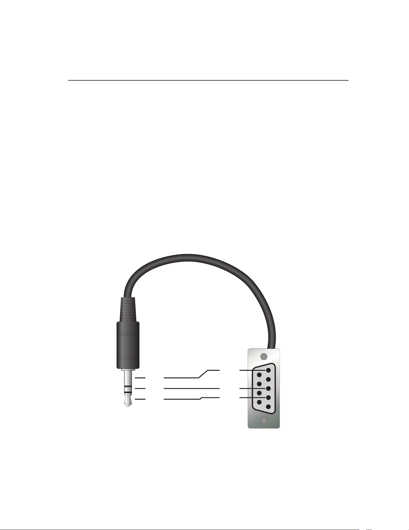
31
Digital Communication Interface
RS-232 Connection
7 Digital Communication Interface
This instrument is capable of communicating with and being controlled by other
equipment through the digital serial interface.
With a digital interface, the instrument may be connected to a computer or other
equipment. This allows the user to set the set-point temperature, monitor the
temperature, and access any of the other controller functions, all using remote
communications equipment. Communications commands are summarized in Table 2
on next page.
7.1 RS-232 Connection
The three-conductor jack for the serial port is located on the back of the instrument.
One serial cable is included. Additional or longer cables, of three meters or less, can
be constructed by following the wiring diagram shown in Figure . Note: The TxD
line on one side connects to the RxD line on the other and vice-versa. To reduce the
possibility of electrical interference, the serial cable should be shielded with low
resistance between the connector and the shield and should not be much longer than
is necessary. The protocol for serial communications is 8 data bits, 1 stop bit, and no
parity. Use no ow control. Set the linefeed to ON (all carriage returns are followed by
a linefeed (ASCII decimal 10)), and the duplex to HALF, disabling echo.
Figure 6
1
2
3
4
5
6
7
8
9
RxD
TxD
GND
RxD
TxD
GND
Serial cable wiring
1.888.610.7664 sales@GlobalTestSupply.com
Fluke-Direct.com
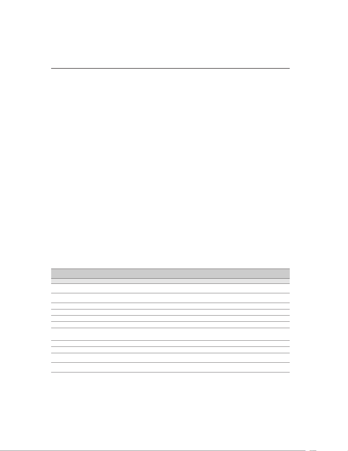
9100S Dry-Well Calibrator
Interface Commands
32
The serial port can be used to transmit measurements to a computer or printer or to
change settings of the instrument from a computer. A full list of commands follows in
Section .
Commands sent to the instrument must end with an EOS character which is a carriage
return (CR, ASCII 13) or linefeed character (LF, ASCII 10). Commands can be
sent with upper or lower case letters. Data returned from the instrument ends with a
carriage return. If the linefeed setting is on, a linefeed character is also sent afer the
carriage return.
7.2 Interface Commands
The various commands for accessing the calibrator functions via the digital interface
are listed in this section (see Table ). These commands are used with the RS-232
serial interface. The commands are terminated with a carriage-return character (CR,
ASCII 13). The interface makes no distinction between upper and lower case letters,
hence either may be used. Commands may be abbreviated to the minimum number of
letters which determines a unique command. A command may be used to either set a
parameter or display a parameter depending on whether or not a value is sent with the
command following a “=” character. For example “s” returns the current set-point and
“s=150.0” sets the set-point to 150.0 degrees.
In the following list of commands, characters or data within brackets, “[” and “]”, are
optional for the command. A slash, “/”, denotes alternate characters or data. Numeric
data, denoted by “n”, may be entered in decimal or exponential notation. Characters
are shown in lower case although upper case may be used. Spaces may be added
within command strings and will simply be ignored. Backspace (BS, ASCII 8) may be
used to erase the previous character. A terminating (CR, ASCII 13) is implied with all
commands.
Table 2 Controller communications commands
Command Description
Command
Format
Command
Example
Returned
Returned
Example
Acceptable
Values
Display Temperature
Read current set-point s[etpoint] s set: 9999.99 {C
or F}
set: 150.00 C
Set current set-point to n s[etpoint]=n
or t[emperature]=n
s=350
t=350
Instrument Range
Read temperature t[emperature] t t: 9999.9 {C or F} t: 55.6 C
Read temperature units u[nits] u u: x u: C
Set temperature units: u[nits]=c/f C or F
Set temperature units to Celsius
u[nits]=c u=c
Set temperature units to
Fahrenheit
u[nits]=f u=f
Read scan mode sc[an] sc sc: {ON or OFF} sc: ON
Set scan mode sc[an]=on/off sc=on ON or OFF
Read scan rate sr[ate] sr srat: 99.9 {C or
F}/min
srat:12.4 C/min
Set scan rate sr[ate]=n sr=1.1 0.1 to 99.9°C
0.2 to 179.8°F
1.888.610.7664 sales@GlobalTestSupply.com
Fluke-Direct.com
33
Digital Communication Interface
Interface Commands
Command Description
Command
Format
Command
Example
Returned
Returned
Example
Acceptable
Values
Secondary Menu
Read proportional band setting pr[op-band] pr pb: 999.9 pb: 15.9
Set proportional band to n pr[op-band]=n pr=8.83 0.1 to 30°C
0.2 to 54°F
Read heater power
(duty cycle)
po[wer] po po: 999.9 po: 6.5
Conguration Menu
Operating Parameters Menu
Read High Limit hl[imit] hl hl: 9999.9 hl: 375.0
Set High Limit hl[imit]=n hl=300 125.0 to 375.0°C
257.0 to 707°F
Serial Interface Menu
Read serial sample setting sa[mple] sa sa: 99999 sa: 1
Set serial sampling setting to n
seconds
sa[mple]=n sa=0 0 to 10,000
Set serial duplex mode: du[plex]=f[ull]/
h[alf]
FULL or HALF
Set serial duplex mode to full
du[plex]=f[ull] du=f
Set serial duplex mode to half
du[plex]=h[alf] du=h
Set serial linefeed mode: lf[eed]=on/of[f] ON or OFF
Set serial linefeed mode to on
lf[eed]=on lf=on
Set serial linefeed mode to off
lf[eed]=of[f] lf=of
Calibration Menu
Read R0 calibration parameter r[0] r r0: 999.999 r0: 100.7
Set R0 calibration parameter to n r[0]=n r=100.7 95.0 to 105.0
Read ALPHA calibration
parameter
al[pha] al al: 9.99999999 al: 0.003865
Set ALPHA calibration parameter
to n
al[pha]=n al=0.003865 0.002 to 0.006
Read DELTA calibration parameter de[lta] de de: 1.50
Set DELTA calibration parameter de[lta]=n de=1.37 de: 9.99999 0–3.0
Miscellaneous Other Commands
Read rmware version number *ver[sion] *ver ver.9999x,9.99 ver.9100S,1.01
Read structure of all commands h[elp] h list of commands
Read ALL operating parameters all all list of parameters
Read setpoint resistance *sr *sr 999.999 ohms 110.023 ohms
Legend: [] Optional command data
{} Returns either information
n Numeric data supplied by user
9 Numeric data returned to user
x Character data returned to user
Note: When DUPLEX is set to FULL and a command is sent to READ, the command is returned followed
by a carriage return and linefeed. Then the value is returned as indicated in the RETURNED
column.
1.888.610.7664 sales@GlobalTestSupply.com
Fluke-Direct.com
35
Test Probe Calibration
Dry-well Characteristics
8 Test Probe Calibration
For optimum accuracy and stability, allow the calibrator to warm up for 10 minutes
after power-up and then allow adequate stabilization time after reaching the set-point
temperature. After completing operation of the calibrator, allow the well to cool by
setting the temperature to 25°C for one-half hour before switching the power off.
8.1 Calibrating a Single Probe
Insert the probe to be calibrated into the well of the instrument. The probe should
t snugly into the calibrator probe sleeve yet should not be so tight that it cannot be
easily removed. Avoid any dirt or grit that may cause the probe to bind in the sleeve.
Best results are obtained with the probe inserted to the full depth of the well. Once the
probe is inserted into the well, allow adequate stabilization time to allow the test probe
temperature to settle as described above. Once the probe has settled to the temperature
of the well, it may be compared to the calibrator display temperature. The display
temperature should be stable to within 0.1°C degree for best results.
CAUTION: Never allow foreign material into the probe holes of the block.
Fluids and other materials can damage the instrument causing binding and
damage to your probe.
8.2 Dry-well Characteristics
There is a temperature gradient vertically in the test well. The heater has been applied
to the block in such a way as to compensate for nominal heat losses out of the top of
the dry-well. However, actual heat losses vary with design of the thermometer probes
inserted into the calibrator and the temperature. For best results, insert probe to full
depth of well.
8.2.1 Stabilization and Accuracy
The stabilization time of the instrument depends on the conditions and temperatures
involved. Typically, the test well stabilizes to 0.1°C within 5 minutes of reaching the
set-point temperature as indicated by the display. Ultimate stability is achieved 10 to
20 minutes after reaching the set temperature.
Inserting a cold probe into a warm well requires another period of stabilizing
depending on the magnitude of the disturbance and the required accuracy. For
example, inserting a 0.25 inch diameter room temperature probe into a sleeve at 300°C
takes 5 minutes to be within 0.3°C of its settled point and might take 10 minutes to
achieve maximum stability.
Speeding up the calibration process can be accomplished by knowing how soon to
make the measurement. It is recommended that typical measurements be made at the
desired temperatures with the desired test probes to establish these times.
1.888.610.7664 sales@GlobalTestSupply.com
Fluke-Direct.com

37
Calibration Procedure
Calibration Procedure
9 Calibration Procedure
Note: This procedure is to be considered a general guideline. Each laboratory
should write their own procedure based on their equipment and their quality
program. Each procedure should be accompanied by an uncertainty analysis
also based on the laboratory’s equipment and environment.
Sometimes the user may want to calibrate the dry-well to improve the temperature
set-point accuracy. Calibration is done by adjusting the controller probe calibration
constants R0 , ALPHA, and DELTA so that the temperature of the dry-well as
measured with a standard thermometer agrees more closely with the set-point. The
thermometer used must be able to measure the well temperature with higher accuracy
than the desired accuracy of the dry-well. By using a good thermometer and following
this procedure the dry-well can be calibrated to an accuracy of better than 0.5°C over
its full range.
9.1 Calibration Points
In calibrating the dry-well, R0, ALPHA, and DELTA are adjusted to minimize the
set-point error at each of three different dry-well temperatures. Any three reasonably
separated temperatures may be used for the calibration. Improved results can be
obtained for shorter ranges when using temperatures that are just within the most
useful operating range of the dry-well. The farther apart the calibration temperatures,
the greater the calibrated temperature range. However, the calibration error is also
greater over the range. For instance, if 150°C to 350°C is chosen as the calibration
range, the calibrator may achieve an accuracy of say ±0.3°C over the range 150°C to
350°C. Choosing a range of 200°C to 300°C may allow the calibrator to have a better
accuracy of maybe ±0.2°C over the range 175°C to 325°C but outside that range the
accuracy may be only ±0.5°C.
9.2 Calibration Procedure
1. Choose three set points to use in the calibration of the R0, ALPHA, and DELTA
parameters. These set points are generally 50.0°C, 200°C, and 350.0°C but
other set points may be used if desired or necessary.
2. Set the dry-well to the lowest set-point. When the dry-well reaches the set-point
and the display is stable, wait 15 minutes or so and then take a reading from
the thermometer (T
1
). Sample the set-point resistance of the dry-well (R
1
) by
holding down “SET” and pressing d. Write these values down as T
1
and R
1
respectively.
3. Repeat step 2 for the other two set-points recording them as T
2
and R
2
and T
3
and R
3
respectively.
4. Using this recorded data, calculate new values for R0, ALPHA, and DELTA
using the following formula:
1.888.610.7664 sales@GlobalTestSupply.com
Fluke-Direct.com

9100S Dry-Well Calibrator
Calibration Procedure
38
9.2.1 Compute DELTA
A T T= −
3 2
B T T= −
2 1
C
T T
T T
=
−
−
−
3 3
2 2
100
1
100 100
1
100
D
T T T T
=
−
−
−
2 2 1 1
100
1
100 100
1
100
E R T= −
3 2
F R T= −
2 1
delta
AF BE
DE CF
=
−
−
where:
T
1
and R
1
are the measured temperature and set-point resistance at 50.0 °C
T
2
and R
2
are the measured temperature and set-point resistance at 200.0 °C
T
3
and R
3
are the measured temperature and set-point resistance at 350.0 °C
9.2.2 Compute R0 and ALPHA
a T de lta
T T
1 1
1 1
100
1
100
= +
−
a T delta
T T
3 3
3 3
100
1
100
= +
−
rzero
R a R a
a a
=
−
−
3 1 1 3
1 3
alpha
R R
R a R a
=
−
−
1 3
3 1 1 3
delta is the new value of DELTA computed above (Section )
1.888.610.7664 sales@GlobalTestSupply.com
Fluke-Direct.com

39
Calibration Procedure
Calibration Procedure
Program the new values for DELTA (delta), R0 (rzero), and ALPHA (alpha) into the
instrument (see Section 6.12, Calibration Parameters on page 27 and Figure 5 on page
21).
9.2.3 Accuracy and Repeatability
Check the accuracy of the dry-well at various points over the calibration range. If dry-
well does not pass specication at all set-points, repeat the Calibration Procedure.
1.888.610.7664 sales@GlobalTestSupply.com
Fluke-Direct.com

41
Maintenance
10 Maintenance
●●
This instrument has been designed with the utmost care. Ease of operation
and simplicity of maintenance have been a central theme in the product
development. Therefore, with proper care the instrument should require very
little maintenance. Avoid operating the instrument in an oily, wet, dirty, or dusty
environment.
●●
If the outside of the instrument becomes soiled, it may be wiped clean with
a damp cloth and mild detergent. Do not use harsh chemicals on the surface
which may damage the paint.
●●
It is important to keep the well of the calibrator clean and clear of any foreign
matter. Do not use uid to clean out the well.
●●
Use a commercially available plastic or felt brush, of appropriate diameter for
a tight t without any uid, to clean the well. Complete the cleaning process by
using cotton swabs and air to remove any debris.
●●
The dry-well calibrator should be handled with care. Avoid knocking or
dropping the calibrator.
●●
Do not slam the probe stems into the well. This type of action can cause a shock
to the sensor.
●●
If a hazardous material is spilt on or inside the equipment, the user is
responsible for taking the appropriate decontamination steps as outlined by the
national safety council with respect to the material.
●●
If the mains supply cord becomes damaged, replace it with a cord with the
appropriate gauge wire for the current of the instrument. If there are any
questions, call a Fluke Authorized Service Center for more information.
●●
Before using any cleaning or decontamination method except those
recommended by Fluke, users should check with an Authorized Service Center
(see Section 1.4, Authorized Service Centers on page 5) to be sure that the
proposed method will not damage the equipment.
●●
If the instrument is used in a manner not in accordance with the equipment
design, the operation of the dry-well may be impaired or safety hazards may
arise, and the warranty may be voided.
1.888.610.7664 sales@GlobalTestSupply.com
Fluke-Direct.com

43
Troubleshooting
Troubleshooting Problems, Possible Causes, and Solutions
11 Troubleshooting
This section contains information on troubleshooting, CE Comments, and a wiring
diagram.
11.1 Troubleshooting Problems, Possible Causes, and Solutions
In the event that the instrument appears to function abnormally, this section may help
to nd and solve the problem. Several possible problem conditions are described along
with likely causes and solutions. If a problem arises, please read this section carefully
and attempt to understand and solve the problem. If the problem cannot otherwise be
solved, contact an Authorized Service Center (see Section 1.4, Authorized Service
Centers on page 5) for assistance. Be sure to have the instrument’s model number,
serial number, voltage, and problem description available.
Problem Possible Causes and Solutions
Incorrect
temperature
reading
Incorrect R0, ALPHA, and DELTA parameters. Find the value for R0, ALPHA,
and DELTA on the Report of Calibration. Reprogram the parameters into the
instrument (see Section , Calibration Parameters). Allow the instrument to
stabilize and verify the accuracy of the temperature reading.
Controller locked up. The controller may have locked up due to a power surge
or other aberration. Initialize the system by performing the Factory Reset
Sequence.
Factory Reset Sequence. Hold the SET and EXIT buttons down at the same time
while powering up the instrument. The instrument displays shows ‘-init-‘, the
model number, and the rmware version. Each of the controller parameters and
calibration constants must be reprogrammed. The values can be found on the
Report of Calibration.
The instrument
heats or cools
too quickly or too
slowly
Incorrect scan and scan rate settings. The scan and scan rate settings may be set
to unwanted values. Check the Scan and Scan Rate settings. The scan may be
off (if the unit seems to be responding too quickly). The scan may be on with the
Scan Rate set low (if unit seems to be responding too slowly).
Improper line voltage. Verify that the voltage reading in the bottom of the unit
matches the source voltage.
Unstable display Wait. Allow the instrument to stabilize for a few minutes.
Proportional band may be incorrect. Refer to the proportional band on the Report
of Calibration.
The display
shows any of the
following: err 1
, err 2 , err 3
, err 4 , err 5,
Err 6, or Err 7
Controller problem. The error messages signify the following problems with the
controller.
Err 1 - a RAM error
Err 2 - a NVRAM error
Err 3 - a Structure error
Err 4 - an ADC setup error
Err 5 - an ADC ready error
Err 6 – a defective control sensor
Err 7 – a heater error
Initialize the system by performing the Factory Reset Sequence describe above.
Temperature
cannot be set
above a certain
point
Incorrect High Limit parameter. The High Limit parameter may be set below
375°C. Check this value as described in Section 6.9, Operating Parameters on
page 25.
1.888.610.7664 sales@GlobalTestSupply.com
Fluke-Direct.com

11.2 CE Comments
11.2.1 EMC Directive
Fluke’s equipment has been tested to meet the European Electromagnetic Compatibility
Directive (EMC Directive, 89/336/EEC). The Declaration of Conformity for your
instrument lists the specic standards to which the unit was tested.
11.2.2 Low Voltage Directive (Safety)
In order to comply with the European Low Voltage Directive (73/23/EEC), Fluke
equipment has been designed to meet the IEC 1010-1 (EN 61010-1) and the IEC 1010-2-
010 (EN 61010-2-010) standards.
1.888.610.7664 sales@GlobalTestSupply.com
Fluke-Direct.com