Installation Guide
Quality, Design and Innovation
home.liebherr.com/fridge-manuals
Contents
1 General safety instructions.................................. 2
2 Installation conditions.......................................... 3
2.1 Location......................................................................... 3
2.2 Building the appliance into kitchen units................ 3
2.3 Installing multiple appliances.................................... 4
2.4 Mains connection......................................................... 5
3 Installation dimensions........................................ 5
4 Ventilation requirements...................................... 5
5 Water connection*................................................ 5
5.1 Dimensions for the water connection*.................... 6
5.2 Water pressure............................................................. 6
6 Transporting appliance......................................... 6
7 Unpacking the appliance...................................... 6
8 Mounting wall spacers.......................................... 6
9 Setting up the appliance....................................... 6
10 Setting up the appliance so that it is level........... 7
11 After setting up..................................................... 7
12 Disposing of packaging......................................... 7
13 Door hinge change................................................ 7
13.1 Removing the upper soft stop mechanism*............ 7
13.2 Removing the bottom soft stop mechanism*......... 9
13.3 Undoing the cable connection................................... 10
13.4 Removing the top door*.............................................. 11
13.5 Removing the bottom door*....................................... 11
13.6 Moving the upper bearing parts to the other side. 12
13.7 Moving the central bearing parts to the other
side*............................................................................... 14
13.8 Moving the lower bearing parts to the other side.. 14
13.9 Moving the door bearing parts to the other side.... 15
13.10 Moving the handles to the other side*..................... 15
13.11 Fitting the bottom door*............................................. 16
13.12 Fitting the top door...................................................... 17
13.13 Fitting the cable connection...................................... 17
13.14 Aligning the doors*...................................................... 18
13.15 Fitting the bottom soft stop mechanism*............... 18
13.16 Fitting the top soft stop mechanism*...................... 19
14 Connecting the appliance to the water supply*.. 19
14.1 Connecting the hose*................................................. 20
14.2 Checking the water system........................................ 20
15 Water tank............................................................. 21
15.1 Inserting the water tank............................................. 21
16 Water filter............................................................ 21
16.1 Inserting the water filter............................................. 21
17 Connecting device................................................. 21
The manufacturer is continually working on the further
development of all types and models. Please be aware that
we reserve the right to make changes to the shape, equip‐
ment and technology.
Symbol Explanation
Read instructions
Please read the information in these instruc‐
tions carefully to understand all of the benefits
of your new appliance.
Symbol Explanation
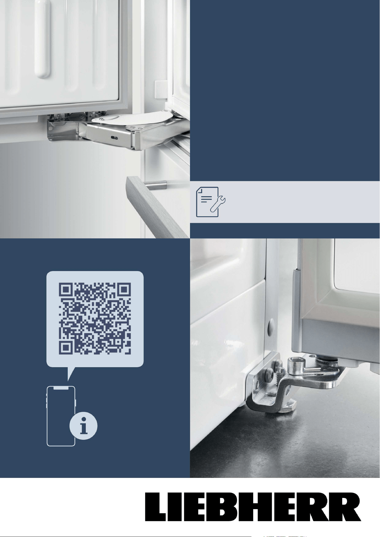
Full instructions on the internet
You can find detailed instructions on the
internet using the QR code on the front
of these instruction or by entering the
service number at
home.liebherr.com/fridge-
manuals.
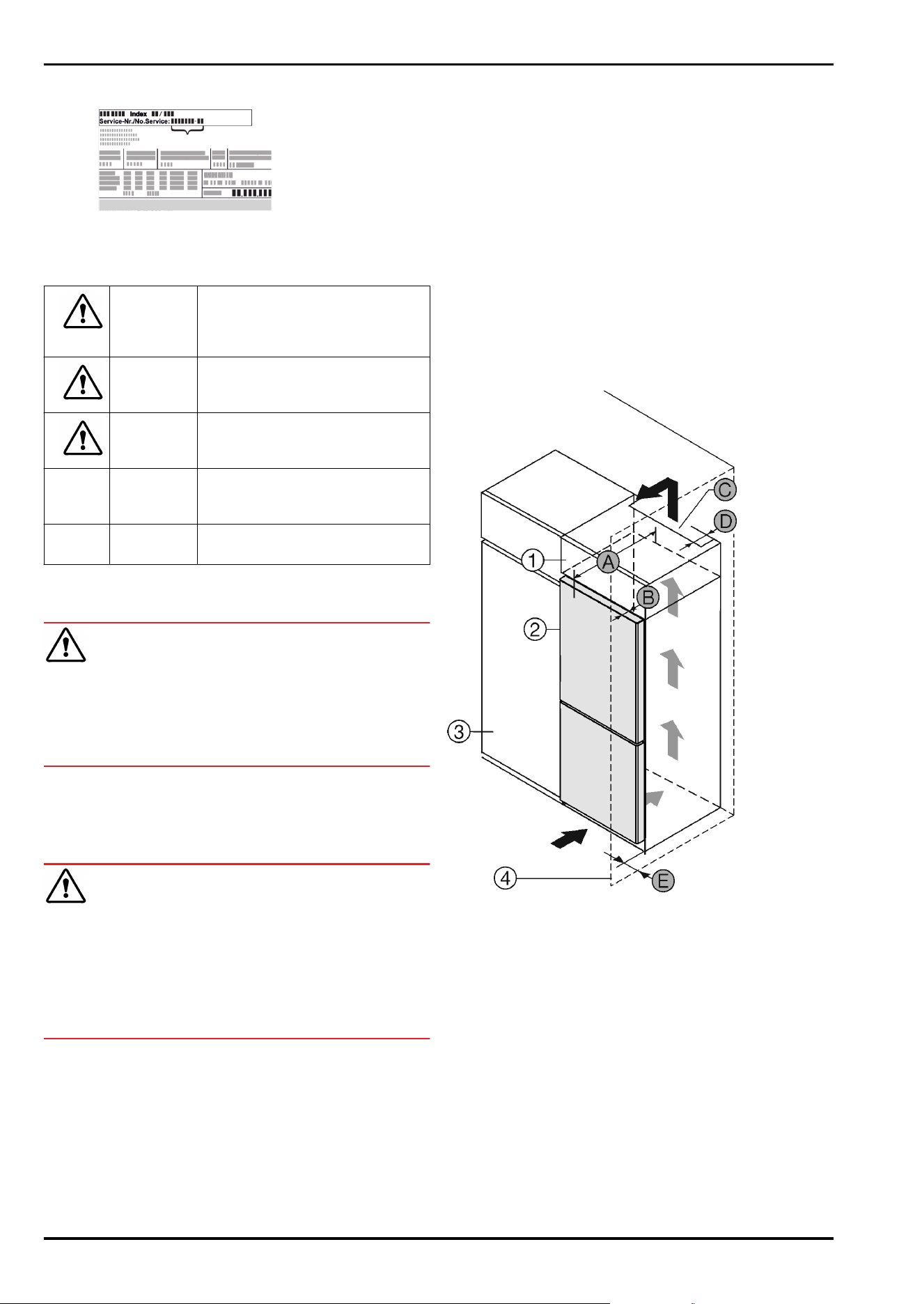
The service number can be found on the serial
tag:
Fig.Example illustration
Check appliance
Check all parts for transport damage. If you
have any complaints, please contact your
agent or customer service.
Differences
These instructions apply to a range of models,
so differences are possible. Sections that
apply to certain models only are marked with
an asterisk (*).
Instructions and results
Instructions are marked with a
.
Results are marked with a
.
Videos
Videos about the appliances are available on
the YouTube channels of Liebherr-Hausgeräte.
1 General safety instructions
-
Please keep this assembly manual in a safe
place so you can refer back to it at any
time.
-
If you pass the appliance on, please hand
this assembly manual to the next user.
-
Read this assembly manual carefully before
installation and use to ensure safe and
correct use of the appliance. Follow
the instructions, safety instructions and
warning messages included at all times.
They are important for ensuring you can
operate and install the appliance safely and
without any problems.
-
First read the general safety instructions in
the “General safety instructions” section of
the operating instructions, which accom‐
pany these installation instructions, and
follow them. If you cannot find the
operating instructions, you can down‐
load the operating instructions from the
internet by entering the service number
at
home.liebherr.com/fridge-manuals. The
General safety instructions
2 * Depending on model and options
service number can be found on the serial
tag:
-
Observe the warning messages and other
detailed information in the other sections
when installing the appliance:
DANGER identifies a situation involving
direct danger which, if not obvi‐
ated, may result in death or severe
bodily injury.
WARNING identifies a dangerous situation
which, if not obviated, may result
in death or severe bodily injury.
CAUTION identifies a dangerous situation
which, if not obviated, may result
in minor or medium bodily injury.
NOTICE identifies a dangerous situation
which, if not obviated, may result
in damage to property.
Note identifies useful instructions and
tips.
2 Installation conditions
WARNING
Fire hazard due to dampness!
If live parts or the mains lead become damp this may cause
short circuits.
u
The appliance is designed for use in enclosed areas. Do
not operate the appliance outdoors or in areas where it is
exposed to splash water or damp conditions.
Intended use
-
Install and use the appliance in indoor spaces only.
2.1 Location
WARNING
Leaking coolant and oil!
Fire. The coolant contained in the appliance is eco-friendly,
but also flammable. The oil contained in the appliance
is flammable. Escaping coolant and oil can ignite if the
concentration is high enough and in contact with an
external heat source.
u
Do not damage the pipelines of the coolant circuit and
the compressor.
-
If the appliance is installed in a very humid environment,
condensation can build up on the outside of the unit.
Always ensure good airlow and ventilation in the installa‐
tion location.
-
The more refrigerant there is in the appliance, the larger
the space that it is installed in must be. If the space is
too small, any leak may create a flammable mixture of
gas and air. For every 8 g of refrigerant, the installation
space must be at least 1 m
3
. Information regarding the
coolant can be found on the serial tag inside the appli‐
ance.
2.1.1 Supporting floor
-
The floor of the installation site must be horizontal and
even.
-
The surface supporting the appliance must be at the
same level as the surrounding floor.
2.1.2 Positioning
-
Do not install appliance in direct sunlight or next to an
oven, radiator or similar.
-
Install the appliance with the rear panel up against the
wall and always use the supplied wall spacers (see
below).
2.2 Building the appliance into kitchen
units
You can install kitchen cabinets around the appliance.
Fig.1
(1) Top cupboard * (B) Door depth *
(2) Appliance * (C) Ventilation cross section
*
(3) Kitchen cabinet * (D) Distance to the back of
the appliance *
(4) Wall * (E) Distance to the side of
the appliance *
(A) Appliance depth *
You can place the appliance directly beside the kitchen
cabinet Fig.1(3).*
There must be a ventilation shaft at the depth Fig. 1 (D) of
the back of the top cupboard over the entire width of the
top cupboard.*
The ventilation cross-section Fig. 1 (C) must be maintained
under the ceiling.*
If the appliance is set up with the hinges next to a wall
Fig. 1 (4), the distance between the appliance and the wall
must be at least 13mm .*
Installation conditions
* Depending on model and options 3
If the appliance is set up with the hinges next to a wall
Fig. 1 (4), the distance between the appliance and the wall
must be at least 20mm .*
In order to be able to fully open the door, the appliance must
protrude by the depth of the door Fig. 1 (B) from the front
of the kitchen cabinet. The appliance may protrude further
depending on the depth of the kitchen cabinets Fig.1(3) and
whether wall spacers are used.*
Appliances without handle / with recessed grip:*
A
675mm
x
B 75mm
C
Min. 300cm
2
D Min. 50mm
E Min. 13mm
x
The use of wall spacers increases the dimensions by
15mm (see8 Mounting wall spacers) .*
Appliances with recessed grip and glass/stone
front:*
A
682mm
x
B 82mm
C
Min. 300cm
2
D Min. 50mm
E Min. 20mm
x
The use of wall spacers increases the dimensions by
15mm (see8 Mounting wall spacers) .*
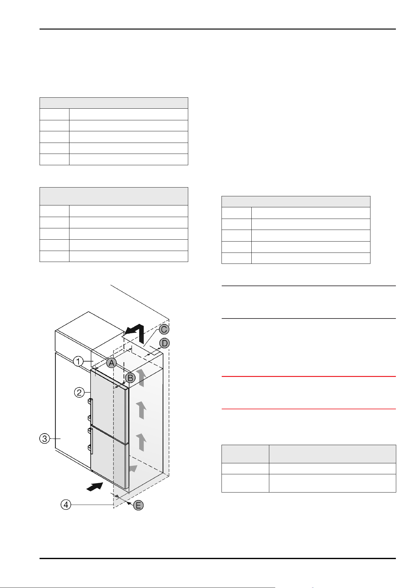
Fig.2
(1) Top cabinet * (B) Door depth *
(2) Appliance * (C) Ventilation cross section
*
(3) Kitchen cabinet * (D) Distance to the back of
the appliance *
(4) Wall * (E) Distance to the side of
the appliance *
(A) Appliance depth *
You can place the appliance directly beside the kitchen
cabinet Fig.2(3).*
There must be a ventilation shaft at the depth Fig. 2 (D) of
the back of the top cupboard over the entire width of the
top cupboard.*
The ventilation cross-section Fig. 2 (C) must be maintained
under the ceiling.*
If the appliance is set up with the hinges next to a wall
Fig. 2 (4), the distance between the appliance and the
wall must be at least 57 mm . This is how far the handle
protrudes when the door is open.*
In order to be able to fully open the door, the appliance must
protrude by the depth of the door Fig. 2 (B) from the front
of the kitchen cabinet. The appliance may protrude further
depending on the depth of the kitchen cabinets Fig. 2 (3)
and whether wall spacers are used.*
Appliances with lever handle:*
A
675mm
x
B 75mm
C
Min. 300cm
2
D Min. 50mm
E Min. 57mm
x
The use of wall spacers increases the dimensions by
15mm (see8 Mounting wall spacers) .*
Note
Please contact Customer Services to acquire a kit to limit
the door opening angle to 90° for appliances with soft close
mechanisms.
Ensure that the following conditions are met:
-
Recess dimensions are adhered to .
-
Ventilation requirements are complied with (see 4 Venti‐
lation requirements) .
2.3 Installing multiple appliances
NOTICE
Risk of damage due to condensate!
u
Do not install the appliance directly alongside a further
refrigerator/freezer.
These appliances are designed for a variety of installation
options. Combine appliances only if the appliance is suit‐
able. The following table shows the installation options by
model:
Installation
option
Model
Single All models
Side-by-side
(SBS)
Model names starting with S....
Installation conditions
4 * Depending on model and options
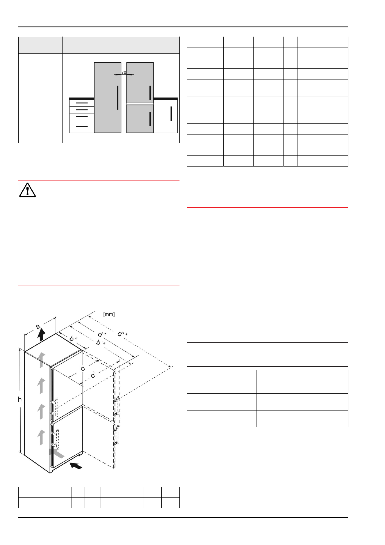
Installation
option
Model
Side-by-side
with a space
of 70 mm
between the
appliances
Otherwise
condensation
will build up
between the
units.
All models without side wall heating
Fig.3
Assemble the appliances together, following their specific
installation instructions.
2.4 Mains connection
WARNING
Danger of fire due to incorrect positioning!
If the mains cable or plug touches the back of the appli‐
ance, the vibration can damage the mains cable or the plug
resulting in a short circuit.
u
Make sure the mains cable is not trapped under the appli‐
ance when you position the appliance.
u
Stand the appliance so that it is not touched by connec‐
tors or main cables.
u
Do not connect any appliances to sockets in the area of
the back of the appliance.
u
Do not place and operate multi-sockets/power distribu‐
tors and other electronic devices (such as halogen trans‐
formers) at the back of the appliances.
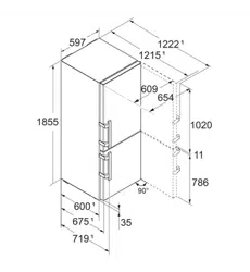
3 Installation dimensions
Fig.4
h a b b` c c` d d`
CN.. 52.. 1855 597
675
x
719
x
609 654
1215
x
1222
x
SCN.. 52..(i) 1855 597
675
x
719
x
609 654
1215
x
1222
x
SBN.. 52..(i) 1855 597
675
x
719
x
609 654
1215
x
1222
x
SWN.. 52..(i) 1855 597
675
x
— 609 —
1215
x
—
CN.. 57..(i) 2015 597
675
x
719
x
609 654
1215
x
1222
x
CBN..
575(i) / 576i
2015 597
675
x
719
x
609 654
1215
x
1222
x
CBN..
578(i) / 579i
2015 597
675
x
— 609 —
1217
x
—
CBN.. 5773 2015 597
682
x
— 609 —
1217
x
—
CN.. 77..(i) 2015 747
675
x
719
x
759 804
1365
x
1372
x
CBN.. 76..(i) 1855 747
675
x
719
x
759 804
1365
x
1372
x
CBN.. 775(i) 2015 747
675
x
719
x
759 804
1365
x
1372
x
CBN.. 778i 2015 747
675
x
— 759 —
1367
x
—
x
For appliances with supplied wall spacers, the dimensions
must be increased by 15mm .
4 Ventilation requirements
NOTICE
Danger of overheating due to insufficient air ventilation!
The compressor may be damaged if there is insufficient air
ventilation.
u
Take care to ensure adequate air ventilation.
u
Observe the ventilation requirements.
If the appliance is integrated into a fitted kitchen, the
following ventilation requirements must be adhered to:
-
There are spacer fins at the back of the appliance to
provide sufficient ventilation. Make sure that these are
not positioned in recesses or openings.
-
As a rule, the larger the ventilation space the more effi‐
ciently the appliance can run.
5 Water connection*
If your appliance has a fixed water connection, a hose is
supplied with it.*
Note
You can purchase a hose of a different length as an acces‐
sory.*
Overview of dimensions
for the water connec‐
tion:*
(see 5.1 Dimensions for the
water connection*) *
Requirements for the
water pressure:
(see 5.2 Water pressure)
Make the water connec‐
tion:
(see 14 Connecting the appli‐
ance to the water supply*)
Installation dimensions
* Depending on model and options 5
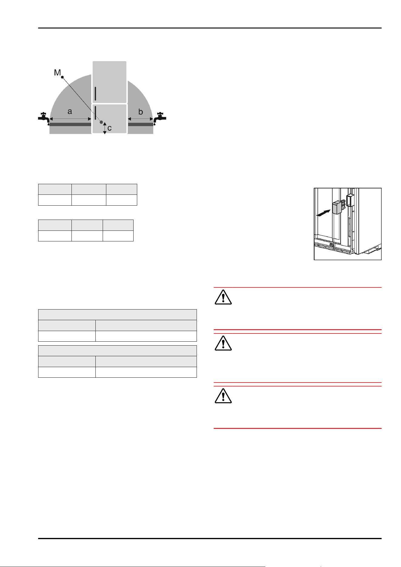
5.1 Dimensions for the water connec‐
tion*
Fig.5
(a) Maximum available
hose length
(c) Distance of solenoid
valve to floor
(b) Maximum available
hose length
(M) Solenoid valve
For 600mm wide appliances:*
a* b* c*
~ 1150mm ~ 1000mm ~ 150mm
For 750mm wide appliances:*
a* b* c*
~ 1075mm ~ 925mm ~ 150mm
5.2 Water pressure
The water connection line and solenoid valve of the appli‐
ance are suitable for a water pressure of up to 1 MPa
(10bar).
To ensure that the appliance functions correctly (flow rate,
ice cube size, noise level), maintain the following water
pressure:
Water pressure:*
bar* MPa*
1.5 to 6.2 0.15 to 0.62
Water pressure when using the water filter:*
bar* MPa*
2.8 to 6.2 0.28 to 0.62
If the pressure is higher than 6.2bar:
u
Fit a pressure reducer.
u
Make the water connection. (see 14 Connecting the appli‐
ance to the water supply*)
6 Transporting appliance
Note when transporting the appliance:
u
Transport the appliance upright.
u
Use two people to transport the appliance.
During first use:
u
Transport the appliance packaged.
When transporting appliances after initial commissioning
(e. g. moving or cleaning):
u
Empty the appliance.
u
Secure the door against unintentional opening.
7 Unpacking the appliance
Before you connect the appliance, report any damage imme‐
diately to the delivery company.
u
Check the appliance and the packaging for damage
during transport. Contact the supplier immediately if you
suspect any level of damage.
u
Remove all materials from the back or the side walls
of the appliance that may prevent proper installation or
ventilation.
u
Remove all protective films from the appliance. Do not
use sharp or pointed objects for this.
8 Mounting wall spacers
With wall spacers, your device achieves the declared energy
consumption and no condensation forms in high ambient
humidity. The device is fully functional without the spacer
brackets, but its energy consumption will be slightly higher.
If you insert the wall spacers, then the device depth
increases by approx.15mm.
u
Appliance with supplied wall
spacers: Fit wall spacers on the
rear of the appliance at the
bottom left and right.
9 Setting up the appliance
CAUTION
Risk of injury due to heavy appliance!
u
Have two people transport the appliance to its installa‐
tion site.
WARNING
Danger of injury and damage due to the appliance being
unstable!
The appliance can topple over.
u
Secure the appliance as described in the instructions.
WARNING
Fire hazard and danger of damage!
u
Do not place appliances emitting heat e.g. microwaves,
toasters etc. on the appliance!
Ensure that the following conditions are met:
q
Only move the device when it is not loaded.
q
Only set up the appliance when someone is available to
help.
Transporting appliance
6 * Depending on model and options
10 Setting up the appliance so
that it is level
CAUTION
Risk of injury or damage from the appliance tipping or the
door falling open!
If the additional adjustable foot on the base support is not
correctly positioned on the floor, there is a risk of the door
falling open or the appliance tipping. This can lead to injury
or property damage.
u
Unscrew the additional adjustable foot on the support
until it reaches the floor.
u
Then turn it another 90°.
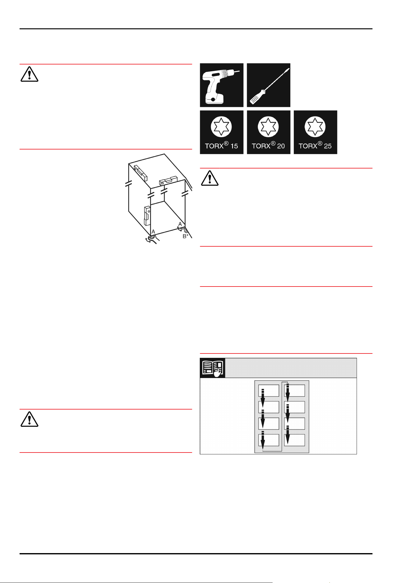
u
Set up the appliance so that
it is level using the supplied
open-ended wrench to turn
the adjustable feet (A) and a
spirit level.
u
Then prop up the door: Turn
the adjustable foot (B) on
the bearing bracket until it
comes into contact with the
floor, then turn an additional
90°.
u
Then prop up the door: Turn the adjustable foot on the
bearing bracket (B) using the open-ended wrench SW10
until it comes into contact with the floor, then turn an
additional 90°.
11 After setting up
u
Take off the protective film from the exterior of the appli‐
ance.
u
Take off the protective film from the trim panels.
u
Take off the protective film from the trim panels and
drawer fronts.
u
Take off the protective film from the stainless steel rear
panel.
u
Remove all transport safety components.
u
Clean the appliance. (see operating instructions)
u
Note the type (model, number), appliance designation,
appliance/serial number, purchase date and dealer’s
address.
12 Disposing of packaging
WARNING
Danger of suffocation due to packing material and plastic
film!
u
Do not allow children to play with packing material.
The packaging is made of recyclable materials:
-
corrugated board/cardboard
-
expanded polystyrene parts
-
polythene bags and sheets
-
polypropylene straps
-
nailed wooden frame with polyethylene panel*
u
Take the packaging material to an official collecting
point.
13 Door hinge change
Tools
Fig.6
WARNING
Danger of injury due to door falling out!
If the bearing parts are not screwed on tightly enough, the
door may fall out. This can result in serious injuries. In
addition, the door may not close with the result that the
appliance does not cool properly.
u
Screw on the bearing brackets/bearing pins tightly with
4Nm.
u
Check all screws and retighten them if necessary.
These sections apply for appliances with a soft stop mech‐
anism:
q
For appliances with a soft stop mechanism
q
For all appliances
NOTICE
Risk of condensation damage for Side-by-Side appliances!*
Certain appliances can be set up as Side-by-Side combina‐
tions (two appliances next to each other).
If your appliance is a Side-by-Side (SBS) appliance:
u
Set up the SBS combination in accordance with the
enclosed document.
If the positioning of the devices is stipulated:
u
Do not change the door hinges over.
Fig.7
Remember the reading direction.
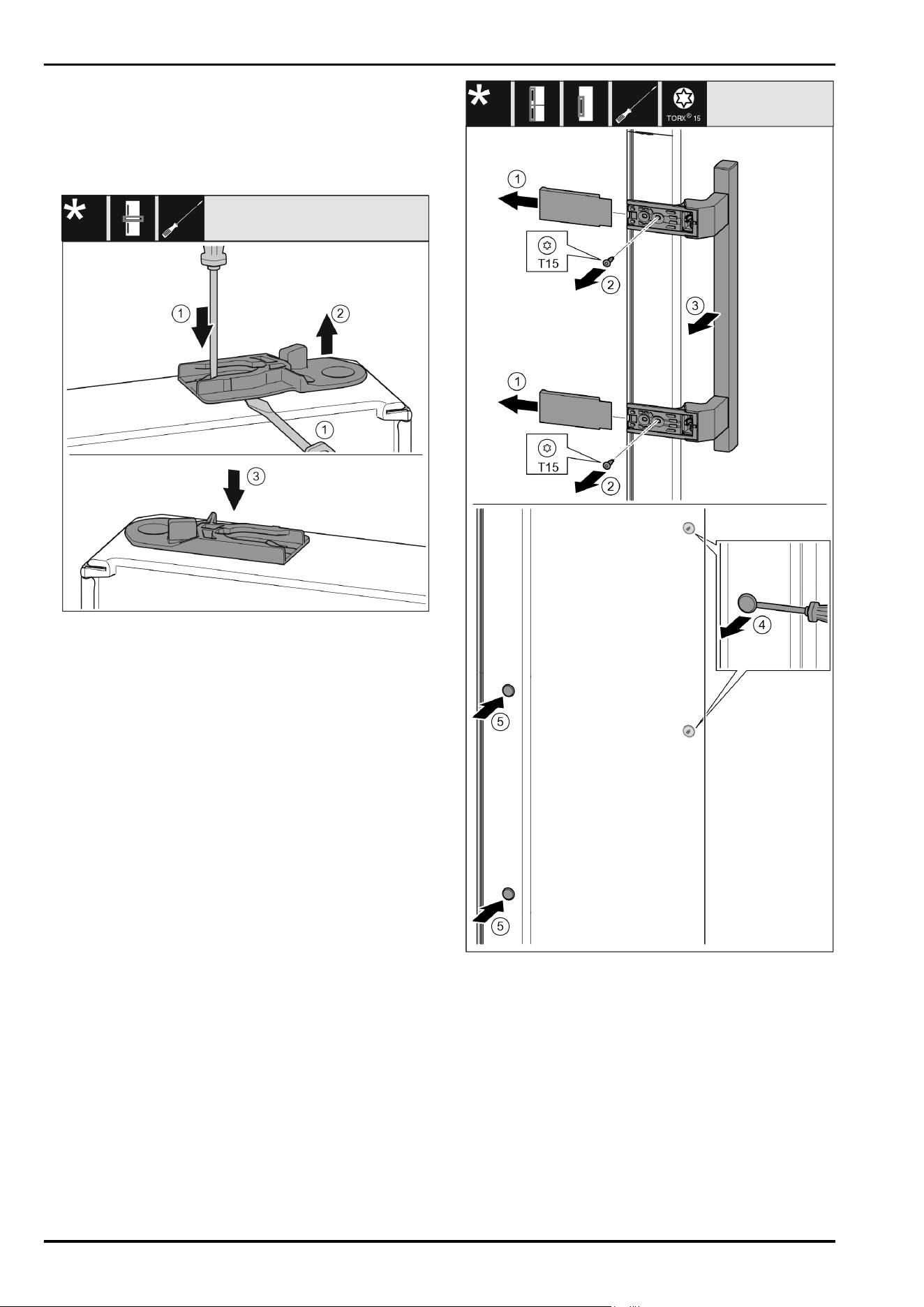
13.1 Removing the upper soft stop
mechanism*
For appliances with a soft stop mechanism:*
Setting up the appliance so that it is level
* Depending on model and options 7
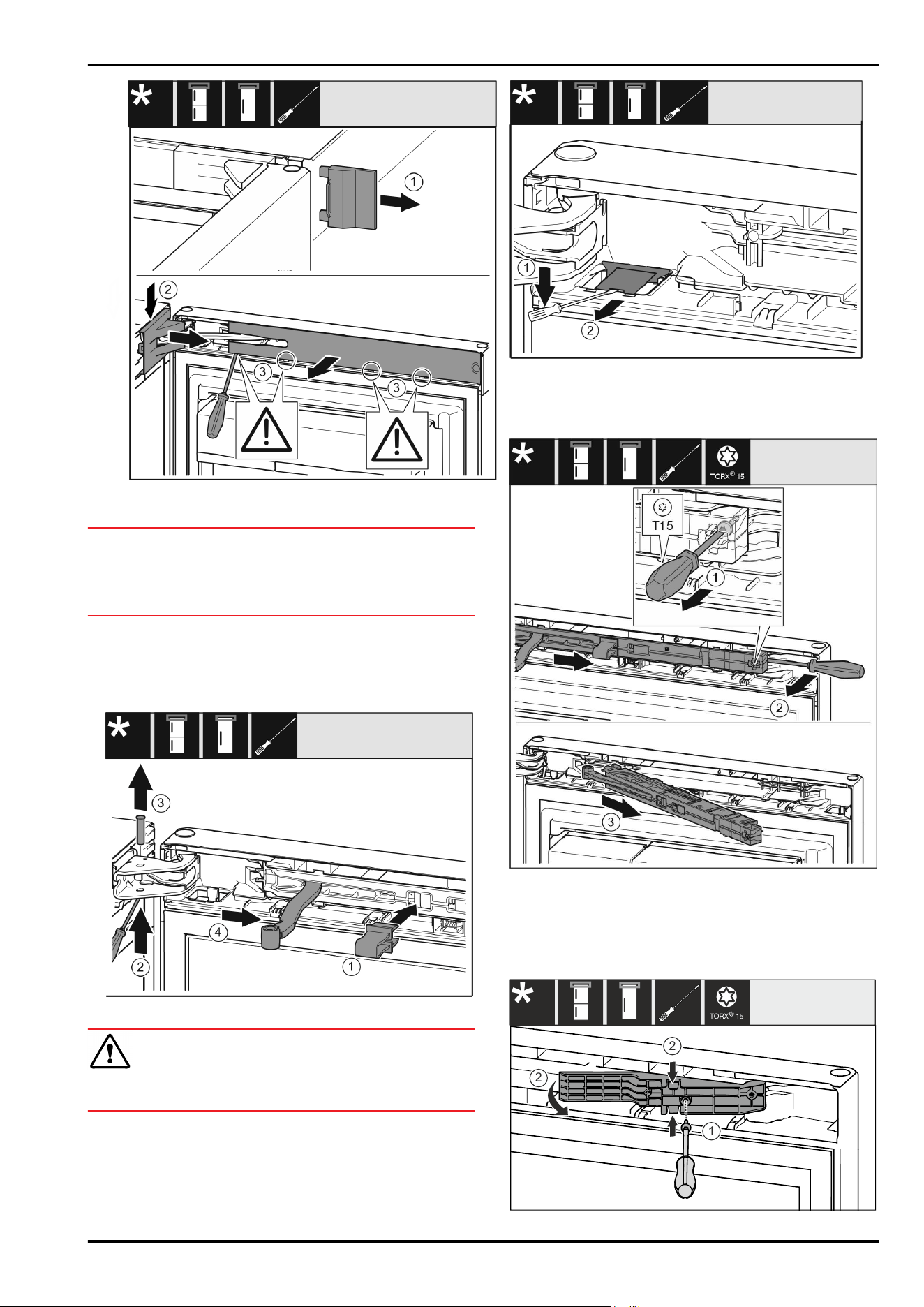
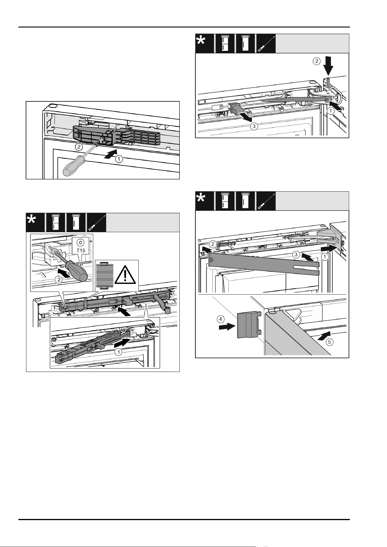
Fig.8
u
Open the top door.*
NOTICE
Risk of damage!
If the door seal is damaged, the door may fail to close prop‐
erly and the cooling will be inadequate.
u
Do not damage the door seal with the screwdriver!
u
Remove the outer cover. Fig.8(1)
u
Disengage and release the bearing bracket cover.
Remove the bearing bracket cover. Fig.8(2)
u
Unlatch the panel with a slotted screwdriver and swivel it
to one side. Fig.8(3)
Fig.9
CAUTION
Crushing hazard by joint folding up!
u
Engage safety device.
u
Engage the locking device in the opening. Fig.9(1)
u
Push out the bolt with a screwdriver. Fig.9(2)
u
Remove the bolt upwards. Fig.9(3)
u
Turn the hinge in the direction of the door. Fig.9(4)
Fig. 10
u
Unlatch the cover with a slotted screwdriver and lift it up.
Fig. 10(1)
u
Take out the cover. Fig. 10(2)
Fig.11
u
Undo the soft stop mechanism screw with a T15 screw‐
driver approx. 14mm. Fig.11(1)
u
Insert a screwdriver behind the soft stop mechanism on
the handle side and rotate the unit forwards. Fig.11(2)
u
Remove the soft stop mechanism. Fig.11(3)
1
2
2
*
TORX 15
Door hinge change
8 * Depending on model and options
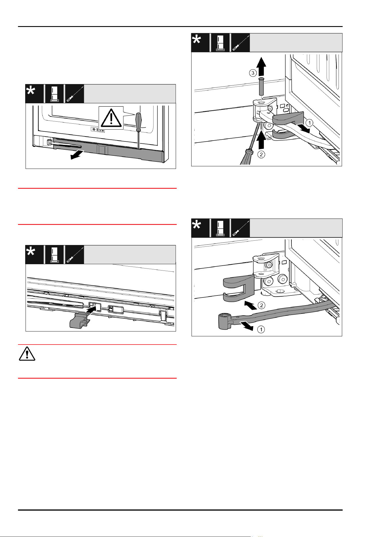
Fig.12*
u
Loosen the screws with the T15 screwdriver. Fig.12(1)*
u
Pull out the adaptor. Fig.12(2)*
13.2 Removing the bottom soft stop
mechanism*
Fig.13
u
Open the bottom door.
NOTICE
Risk of damage!
If the door seal is damaged, the door may fail to close prop‐
erly and the cooling will be inadequate.
u
Do not damage the door seal with the screwdriver!
u
Unlatch the panel with a slotted screwdriver and swivel it
to one side Fig.13().
Fig. 14
CAUTION
Crushing hazard by joint folding up!
u
Engage safety device.
u
Engage the locking device in the opening Fig. 14().
Fig. 15
u
Remove the bearing bracket cover and push it along the
hinge. Fig. 15(1)
u
Lift the bolt with a finger or screwdriver from below.
Fig. 15(2)
u
Insert the screwdriver under the bolt head and pull it out.
Fig. 15(3)
Fig. 16
u
Turn the hinge in the direction of the door. Fig. 16(1)
u
Remove the bearing bracket cover. Fig. 16(2)
Door hinge change
* Depending on model and options 9
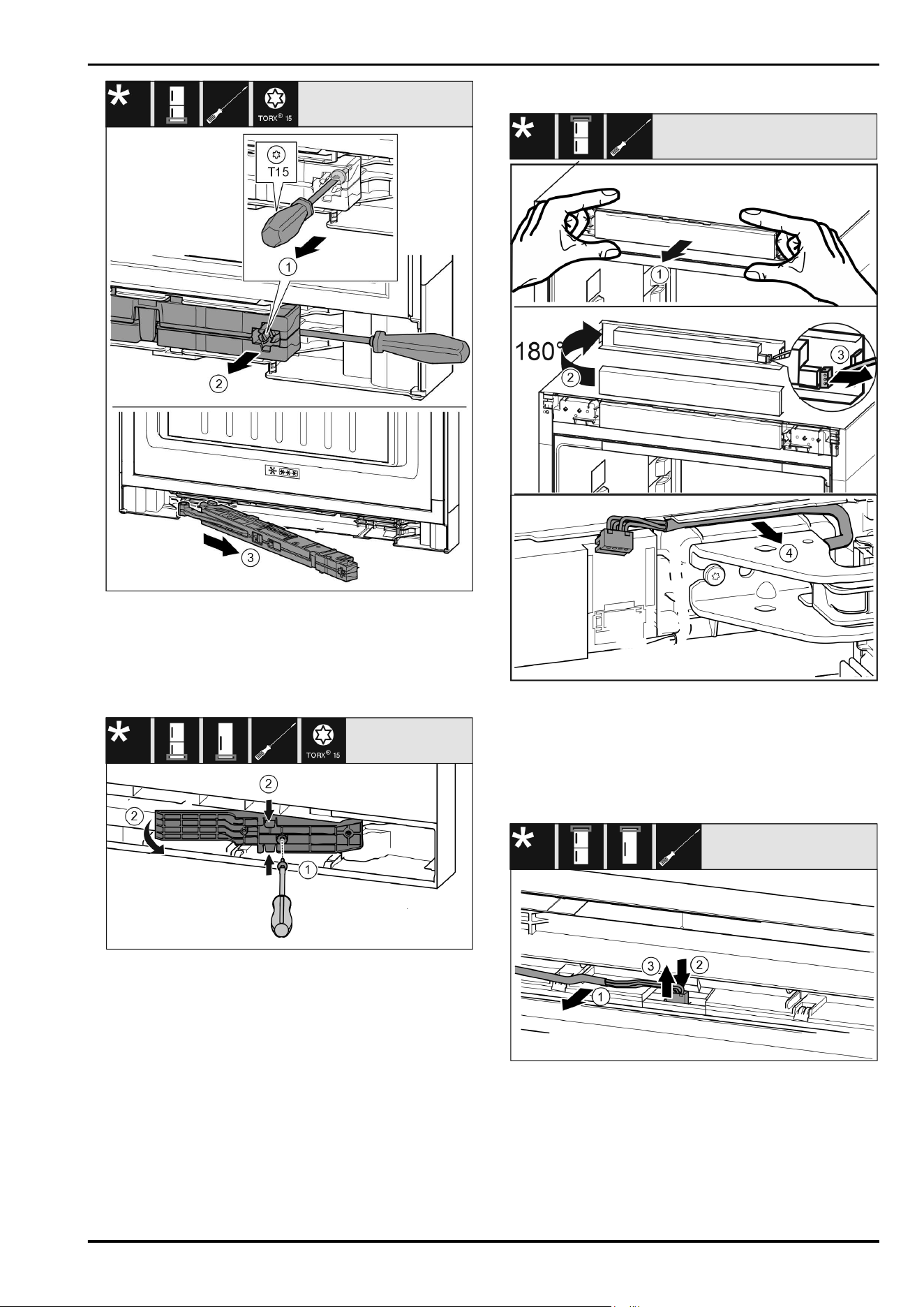
Fig.17
u
Undo the soft stop mechanism screw with a T15 screw‐
driver approx. 14mm. Fig.17(1)
u
Insert the screwdriver on the handle side behind the soft
stop mechanism. Turn the unit forwards. Fig.17(2)
u
Pull out the unit. Fig.17(3)
u
Place the soft stop mechanism to one side.
Fig. 18*
u
Loosen the screws with the T15 screwdriver. Fig. 18(1)*
u
Pull out the adapter. Fig. 18(2)*
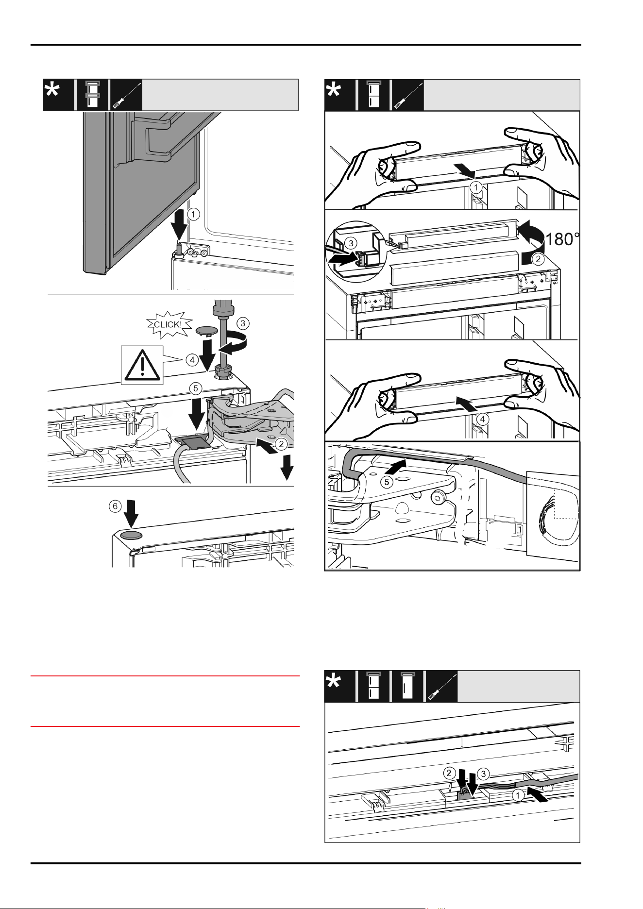
13.3 Undoing the cable connection
Fig. 19
u
Pull out the control panel of the appliance to the front
carefully. Fig. 19(1)
u
Turn the control panel upwards by 180°. Fig. 19(2)
u
Push the latching lug back and pull out the plug carefully.
Fig. 19(3)
u
Carefully pull out the cable over the bearing bracket out
of the guide. Fig. 19(4)
Fig.20
u
Carefully release the grey cable from the guide in the
door. Fig.20(1)
u
Push back the lug behind the plug. Fig.20(2)
u
Pull out the plug carefully upwards. Fig.20(3)
Door hinge change
10 * Depending on model and options
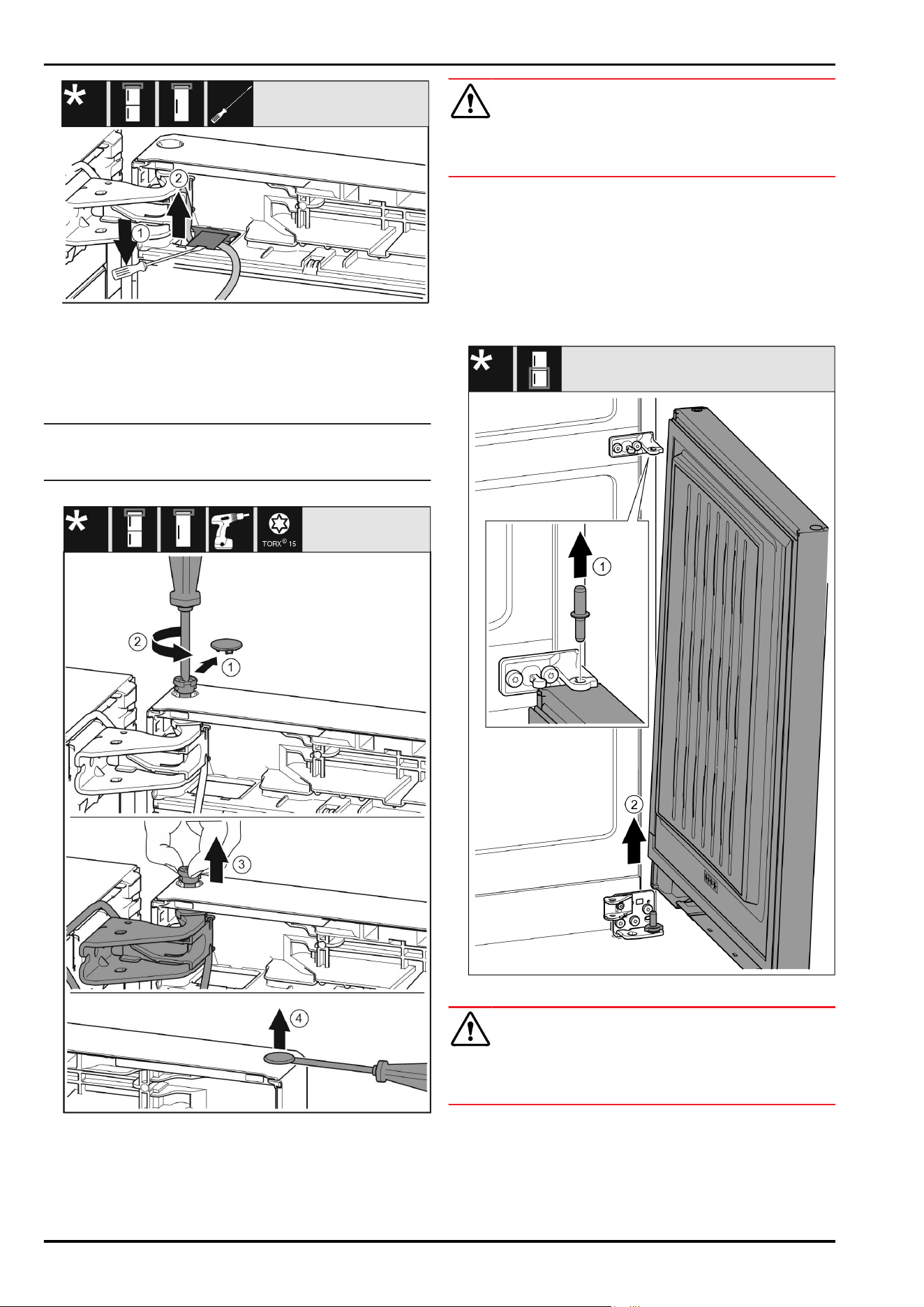
Fig.21
u
Lift up the cover with a screwdriver and pull it out.
Fig.21(1)
u
Pull out the cable. Fig.21(2)
13.4 Removing the top door*
Note
u
Remove any food from the door racks before removing
the door, so that no food falls out.
For all appliances:
Fig.22
CAUTION
Risk of injury if the door tips!
u
Take good hold of the door.
u
Set down the door carefully.
u
Carefully remove the protective cover. Fig.22(1)
u
Undo the bolt a little with a T15 screwdriver. Fig.22(2)
u
Hold the door and remove the bolts with your fingers.
Fig.22(3)
u
Lift the door and place it to one side.
u
Carefully lift the plugs out of the door bearing bush with
a slotted screwdriver and pull them out. Fig.22(4)
13.5 Removing the bottom door*
Fig.23*
CAUTION
Risk of injury if the door tips!
u
Take good hold of the door.
u
Set down the door carefully.
u
Pull out the bolts upwards. Fig.23(1)*
u
Swing the door out, pull it upwards and place it to one
side. Fig.23(2)*
Door hinge change
* Depending on model and options 11
13.6 Moving the upper bearing parts to
the other side
For all appliances:
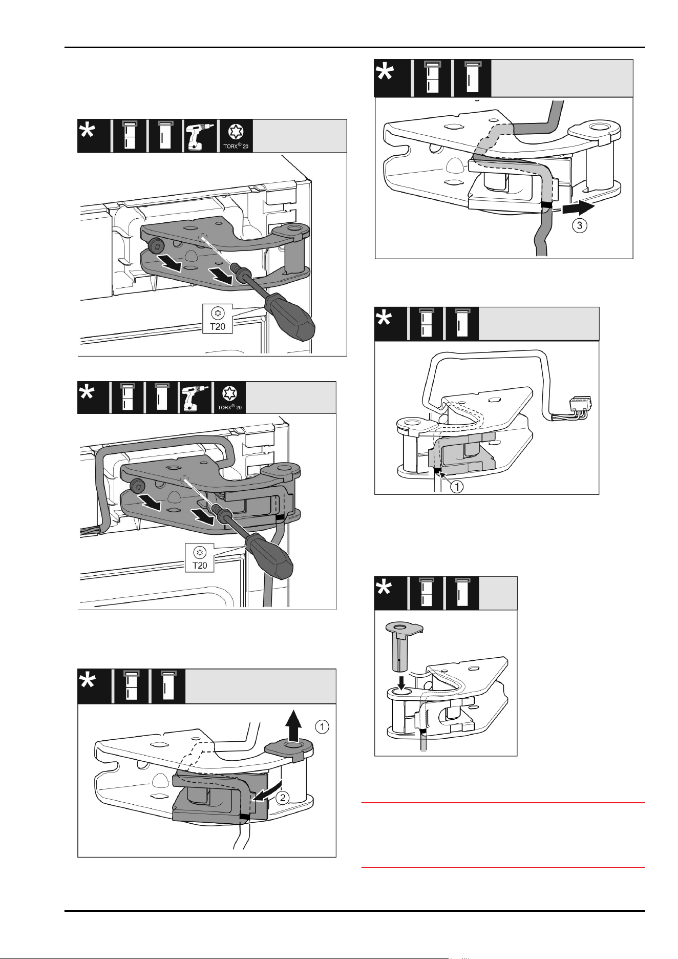
Fig. 24
Fig.25
u
Remove both screws with a T20 screwdriver.
u
Lift up and remove the bearing bracket.
u
Lift up and remove the bearing bracket and cable.
Fig. 26
u
Pull the bearing bush out of the guide. Fig. 26(1)
u
Swing the cable holder out. Fig. 26(2)
Fig.27
u
Remove the cable with the cable holder from the bearing
bracket. Fig.27(3)
Fig.28
u
Insert the cable mirror-inverted in the upper groove of the
cable holder.
w
The middle marking must be positioned on the edge of
the cable holder Fig.28(1).
u
Swing in the cable holder.
Fig.29
u
Insert the bearing bush from the other side and latch it
into place.
NOTICE
Danger of cable crushing
u
Pay attention to the markings when routing the cable.
The cable end with the double marking must be routed
into the door end piece.
Door hinge change
12 * Depending on model and options
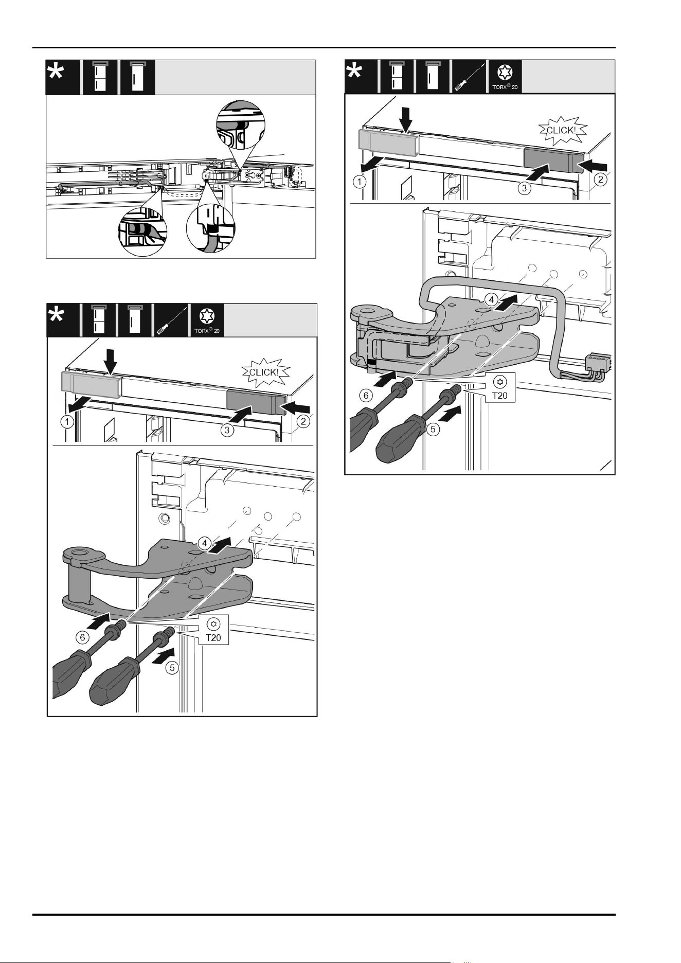
Fig.30
After making the change, the cable routing must be as
shown in the illustration.
Fig.31
u
Take off the cover from above to the front. Fig.31(1)
u
Rotate the cover 180° and clip onto the other side from
the right. Fig.31(2)
u
Latch the cover into place. Fig.31(3)
u
Position the upper bearing bracket. Fig.31(4)
u
Insert the screw with a T20 screwdriver and tighten it.
Fig.31(5)
u
Insert the screw with a T20 screwdriver and tighten it.
Fig.31(6)
Fig.32
u
Take off the cover from above to the front. Fig.32(1)
u
Rotate the cover 180° and clip onto the other side from
the right. Fig.32(2)
u
Latch the cover into place. Fig.32(3)
u
Position the upper bearing bracket. Fig.32(4)
u
Insert the screw with a T20 screwdriver and tighten it.
Fig.32(5)
u
Insert the screw with a T20 screwdriver and tighten it.
Fig.32(6)
Door hinge change
* Depending on model and options 13
13.7 Moving the central bearing parts to
the other side*
Fig.33
u
Take off the washer. Fig.33(1)
u
Remove the screws with a T20 screwdriver. Fig.33(2)
u
Take off the cover carefully. Fig.33(3)
u
Screw the bearing bracket and the film rotated 180°
firmly onto the other side. Fig.33(4)
u
Attach the cover rotated 180° onto the other side.
Fig.33(5)
u
Push the washer on from the front. Fig.33(6)
13.8 Moving the lower bearing parts to
the other side
For all appliances:
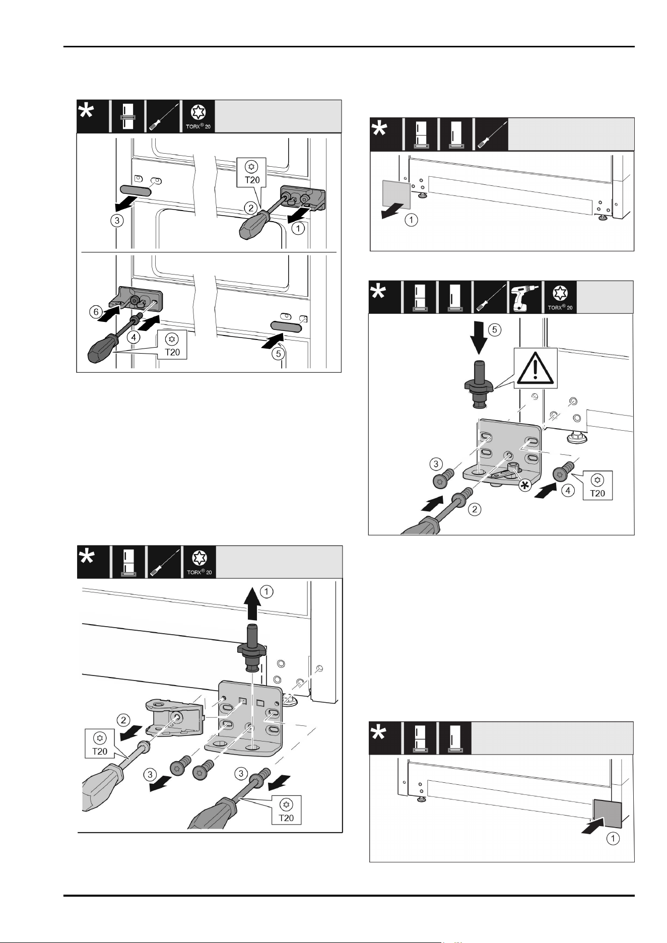
Fig.34*
u
Lift the bearing pin completely upward and pull it out.
Fig.34(1)*
u
Take out the screw with a T20 screwdriver and take off
the soft stop connection. Fig.34(2)*
u
Take out the screws with a T20 screwdriver and take off
the bearing bracket. Fig.34(3)*
For all appliances:
Fig.35
u
Remove the cover. Fig.35(1)
Fig.36
u
Place the bearing bracket on the other side and screw
it on with a T20 screwdriver. Start with screw 2 at the
bottom in the middle. Fig.36(2)
u
Screw in screws 3 and 4 tightly. Fig.36(3,4)
u
Insert the bearing pin completely. Make sure that the
latching lug is pointing to the rear. Fig.36(5)
u
Place the bearing bracket on the other side and screw
it on with a T20 screwdriver. Start with screw 2 at the
bottom in the middle.(2)*
u
Screw in screws 3 and 4 tightly.(3,4)*
u
Rotate the soft stop connection 180°. Screw it in with
a T20 screwdriver on the other side of the bearing
bracket.(5)*
u
Insert the bearing pin completely. Make sure that the
latching lug is pointing to the rear.(6)*
Fig.37
Door hinge change
14 * Depending on model and options
u
Put the cover back on the other side. Fig.37(1)
13.9 Moving the door bearing parts to
the other side
Top of door*
Fig.38*
u
The bottom side of door faces upwards: Turn the door.*
u
Pull out the guide bush: Press the lug with a slotted
screwdriver and, at the same time, insert the slotted
screwdriver under the guide bush. Fig.38(1, 2)*
u
Slide the guide bush included in the scope of supply to
the other side of the housing. Fig.38(3)*
u
The upper side of door faces upwards: Turn the door.*
13.10 Moving the handles to the other
side*
For all appliances:
Fig. 39
u
Pull off the cover. Fig. 39(1)
u
Remove the screws with a T15 screwdriver. Fig. 39(2)
u
Take off the handle. Fig. 39(3)
u
Carefully lift up the side plugs with a slotted screwdriver
and pull them out. Fig. 39(4)
u
Insert the plugs again on the other side. Fig. 39(5)
Door hinge change
* Depending on model and options 15
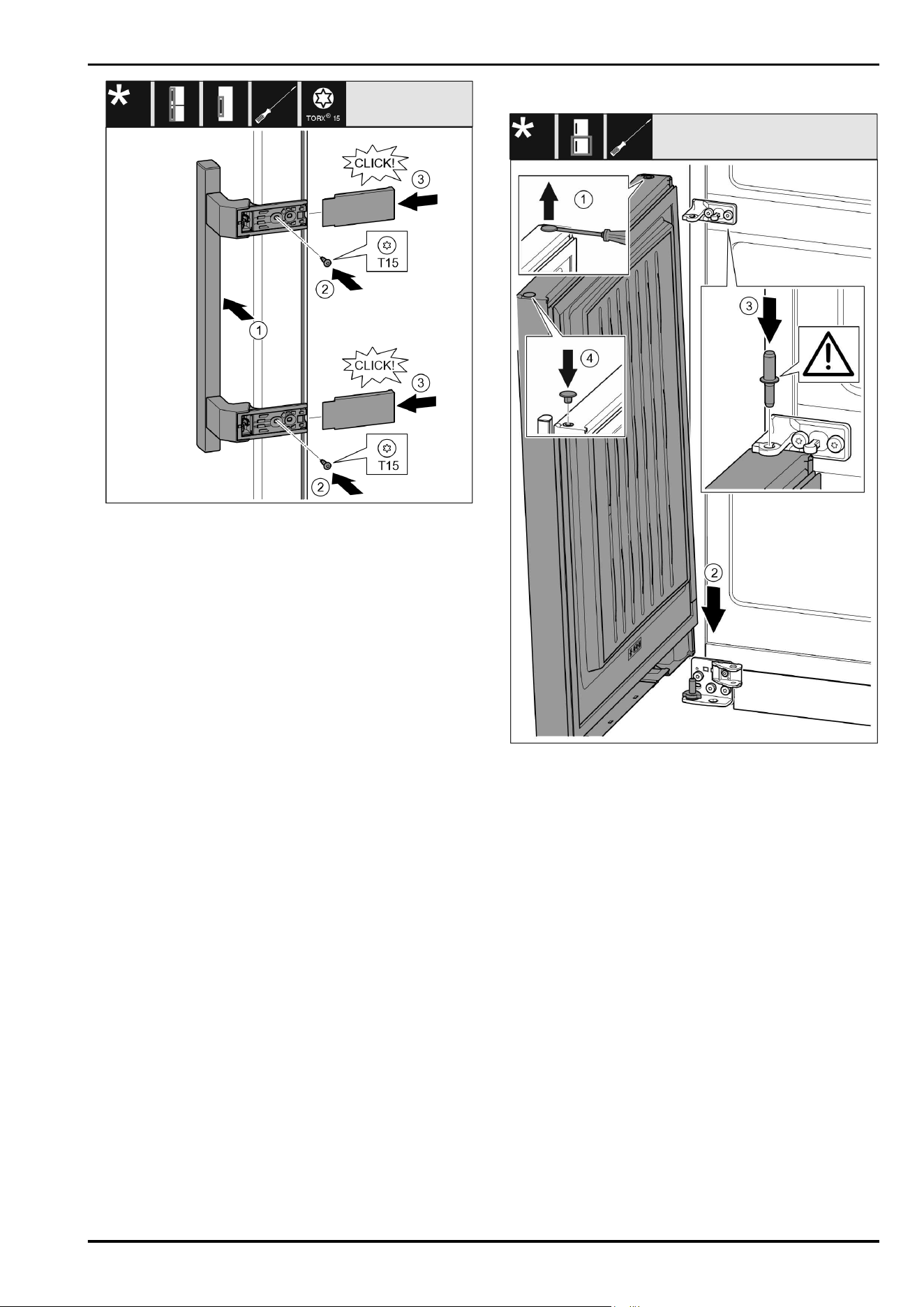
Fig.40
u
Position the handle on the other side. Fig.40(1)
w
The screw holes must be exactly above each other.
u
Tighten the screw with a T15 screwdriver. Fig.40(2)
u
Position the covers on the side and push them on.
Fig.40(3)
w
Ensure that they latch into place.
13.11 Fitting the bottom door*
Fig. 41
u
Carefully lift up the plugs with a slotted screwdriver and
pull them out. Fig. 41(1)
u
Place the door onto the lower bearing pins from above.
Fig. 41(2)
u
Insert the centre bearing pin through the centre bearing
bracket into the lower door. Make sure that the latching
lug is pointing to the rear. Fig. 41(3)
u
Insert the plugs again on the other side of the door.
Fig. 41(4)
Door hinge change
16 * Depending on model and options
13.12 Fitting the top door
Fig. 42
u
Place the upper door on the centre bearing pins Fig. 42(1)
u
Align the top of the door with opening in the bearing
bracket. Fig. 42(2)
u
Insert the bolt and tighten with a T15 screwdriver.
Fig. 42(3)
u
Fit the protective cover to protect the door: Insert the
protective cover and check that it is flush to the door. If
not, insert the bolt fully. Fig. 42(4)
NOTICE
Cable crushing
u
The marking on the cable must lie centrally in the holder.
The lug with the longer opening must point forwards.
u
Place on the cover and press it down until it latches into
place. Fig. 42(5)
u
Insert the plugs. Fig. 42(6)
13.13 Fitting the cable connection
Fig.43
u
Take off the operating panel carefully. Fig.43(1)
u
Turn the panel upwards through 180°. Fig.43(2)
u
Engage the plug in the control panel. Fig.43(3)
u
Latch the control panel back into the appliance.
Fig.43(4)
u
Carefully position the grey cable in the guide above the
top bearing bracket. Fig.43(5)
Door hinge change
* Depending on model and options 17
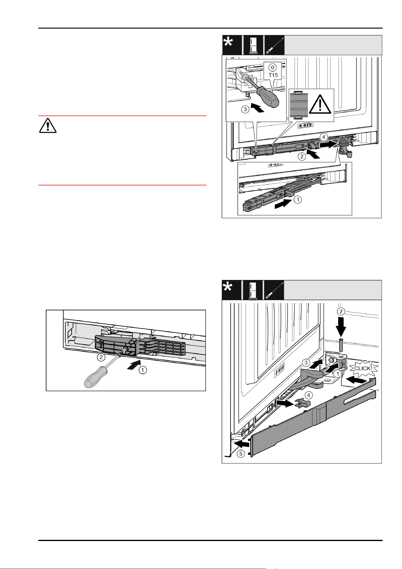
Fig.44
u
Insert the grey cable into the guide in the top door.
Fig.44(1)
u
Press back the latching lug. Fig.44(2)
u
Engage the plug. Fig.44(3)
u
Position the remaining cable length as a loop in the
guide, if required.
13.14 Aligning the doors*
For all appliances:
WARNING
Danger of injury due to door falling out!
If the bearing parts are not screwed on tightly enough, the
door may fall out. This can result in serious injuries. In
addition, the door may not close with the result that the
appliance does not cool properly.
u
Screw the bearing brackets on firmly with 4Nm.
u
Check all screws and retighten them if necessary.
u
Align the doors flush with the appliance housing using
the two slots in the lower bearing bracket and centre
bearing bracket if needed. To do this undo the middle
screw in the bottom bearing bracket with the T20 tool
supplied. Undo the remaining screws a little with the T20
tool or with a T20 screwdriver and align using the slotted
holes. Undo the screws in the middle bearing bracket
with the T20 tool and align the middle bearing bracket
using the slotted holes.*
u
Prop up the door: Take off the adjustable foot on the
bearing bracket using the open-ended wrench SW10 until
it comes into contact with the floor, then turn an addi‐
tional 90°.
13.15 Fitting the bottom soft stop mech‐
anism*
Fig.45*
u
Install the adapter on the handle side in the slot.
Fig.45(1)*
u
Tighten the screw with a T15 screwdriver. Fig.45(2)*
Fig.46
u
Slide the soft stop unit on the bearing bracket side at an
angle into the slot as far as it will go. Fig.46(1)
u
Slide the soft stop unit fully into the slot. Fig.46(2)
w
The unit is positioned correctly when the rib on the soft
stop unit is in the guide.
u
Tighten the screw with a T15 screwdriver. Fig.46(3)
u
Push the cover over the hinge. Fig.46(4)
Fig. 47
The door is open 90°
u
Turn the hinge in the mount. Fig. 47(1)
u
Insert the bolt with a T15 screwdriver in the mount and
hinge. Make sure that the latching lug sits correctly in the
groove. Fig. 47(2)
u
Push the bearing bracket cover along the hinge and fit it
via the mount. Fig. 47(3)
u
Remove the locking device. Fig. 47(4)
Door hinge change
18 * Depending on model and options
u
Position the panel on the handle and swing it in.
Fig. 47(5)
w
The panel is latched into place.
u
Close the bottom door.
13.16 Fitting the top soft stop mecha‐
nism*
For appliances with a soft stop mechanism:
Fig.48*
u
Install the adapter on the handle side in the slot.
Fig.48(1)*
u
Tighten the screw with a T15 screwdriver. Fig.48(2)*
Fig. 49
u
Slide the soft stop unit on the bearing bracket side at an
angle into the slot as far as it will go. Fig. 49(1)
u
Slide the unit in completely.
w
The unit is positioned correctly when the rib on the soft
stop unit is in the guide in the housing.
u
Tighten the screw with a T15 screwdriver. Fig. 49(2)
Fig.50
The door is open 90°.
u
Turn the hinge in the bearing bracket. Fig.50(1)
u
Insert the bolt in the bearing bracket and hinge. Make
sure that the latching lug sits correctly in the groove.
Fig.50(2)
u
Remove the locking device. Fig.50(3)
Fig.51
u
Position the bearing bracket cover and latch it in place. If
necessary push it apart carefully. Fig.51(1)
u
Position the panel. Fig.51(2)
u
Swing in the panel and latch it into place. Fig.51(3)
u
Slide on the outer cover. Fig.51(4)
u
Close the upper door. Fig.51(5)
14 Connecting the appliance to the
water supply*
Make sure that the following requirements are fulfilled:
q
The dimensions for the water supply connection are
known and complied with.
q
The correct water pressure is maintained.
q
Water is supplied to the appliance via a cold water
pipe which can withstand the operating pressure and is
connected to the drinking water supply.
q
All equipment and devices used to supply water must
comply with the regulations in force in the respective
country.
Connecting the appliance to the water supply*
* Depending on model and options 19
q
The rear of appliance is accessible so that you can
connect the appliance to the drinking water supply.
q
The supplied hose is used. Old hoses have been disposed
of.*
q
The hose connector contains a filter with a seal.*
q
There is a tap between the hose line and the domestic
water connection so that you can turn off the water
supply if necessary.*
q
The tap is not directly behind the appliance and is easily
accessible. This way, you can push the appliance as close
as possible to the wall and can quickly turn off the tap if
necessary.*
WARNING
Risk of electric shock from water!
u
Before connecting to the water pipe: Disconnect the
appliance from the mains.
u
Before connecting to water supply lines: Shut off the
water supply.
u
Make sure that only qualified personnel connect the
device to the drinking water supply.
WARNING
Risk of poisoning due to contaminated water!
u
Only connect to the drinking water supply.
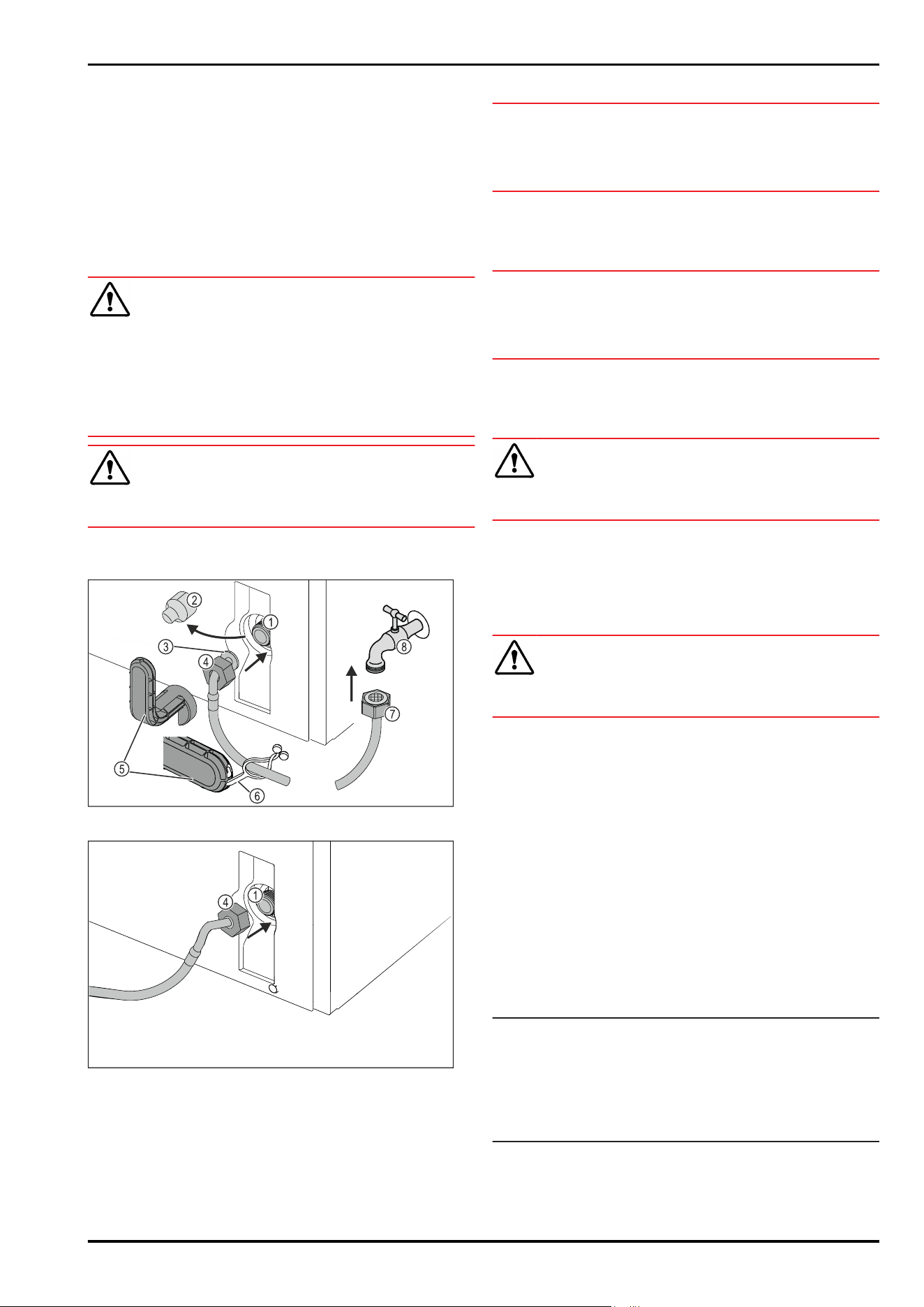
14.1 Connecting the hose*
Fig.52
Fig.52
(1) Solenoid valve: The
solenoid valve is at the
bottom on the back of
the appliance. It has
an R3/4 connecting
thread.
(5) Tool
(2) Cover (6) Lug
(3) Angled hose end (7) Straight hose end
(4) Nut (8) Tap
NOTICE
Risk of damage from incorrect installation!
u
Do not damage or kink the hose.
u
Do not damage or kink the hose when setting up the
appliance.
Connecting the hose to the appliance:
u
Pull off the cover Fig.52(2).
u
Push and hold the nut Fig. 52 (4) all the way over the
angled hose end Fig.52(3).
NOTICE
The solenoid valve will not be tight if the thread is damaged!
If the solenoid valve is not tight, water may leak out.
u
Observe the following instructions for fitting the nut on
the solenoid valve.
u
Carefully position and hold the nut Fig.52(4) on the sole‐
noid valve Fig.52(1).
u
Screw the nut Fig. 52 (4) onto the thread by hand until it
is firmly in place.
WARNING
Danger of cuts if the tool is broken!
u
Only use the tool Fig.52(5) at room temperature.
u
Tighten the nut Fig. 52 (4)clockwise with the tool
Fig. 52 (5) until the maximum torque is reached and the
tool Fig.52(5) no longer tightens.
w
The hose is connected to the appliance.
Connecting the hose to the tap:
u
Screw the nut Fig.52(7) onto the tap Fig.52(8).
WARNING
Danger of cuts if the tool is broken!
u
Only use the tool Fig.52(5) at room temperature.
u
Tighten the nut Fig. 52 (7)clockwise with the tool
Fig. 52 (5) until the maximum torque is reached and the
tool Fig.52(5) no longer tightens.
u
Hook the lug Fig.52(6) into the tool Fig.52(5).
u
Fasten the lug Fig.52(6) to keep it on the hose.
w
The hose is connected to the tap.
14.2 Checking the water system
Before you completely install the appliance, Liebherr recom‐
mends checking the water system for leaks.
u
Put in the InfinitySpring water tank. (see 15 Water tank)
u
Put in the InfinitySpring water filter. (see16 Water filter)
u
Slowly turn on the tap.*
u
Check the hose, water feed and connections for leaks.
w
The water system has now been checked for leaks.
w
The water system is not leaking: You can install up the
appliance completely.
Note
InfinitySpring: Before the first use, you must put the Infin‐
itySpring into operation. To do this you must bleed and
clean the water system. (see Quick Start Guide or operating
instructions)
IceMaker: Before the first use, you must clean the IceMaker.
(see Quick Start Guide or operating instructions)
Connecting the appliance to the water supply*
20 * Depending on model and options
15 Water tank
Depending on your model, the InfinitySpring water tank is
behind the lowest drawer in the fridge or BioFresh compart‐
ment
15.1 Inserting the water tank
Fig.53
u
Remove the drawer compartment.
u
Insert the water tank and rotate approx. 90° clockwise
until it clicks in.
u
Check that the tank is sealed and no water leaks out.
u
Insert the drawer compartment.
u
Vent the water system (see the Installation Instructions,
Water Connection)
Instead of the water filter you can insert an additional water
tank.
Note
You can purchase this water tank as an optional extra.
16 Water filter
Depending on your model, the water filter is behind the
lowest drawer in the fridge or BioFresh compartment.
It filters out deposits in the water and reduces the taste of
chlorine.
q
Replace the water filter at least every 6 months, or if
there is a significant reduction in the flow rate.
q
The water filter contains carbon and can be disposed of
with the regular household waste.
Note
Water filters are available from the Liebherr-Hausgeräte
store at
home.liebherr.com/shop/de/deu/zubehor.html.
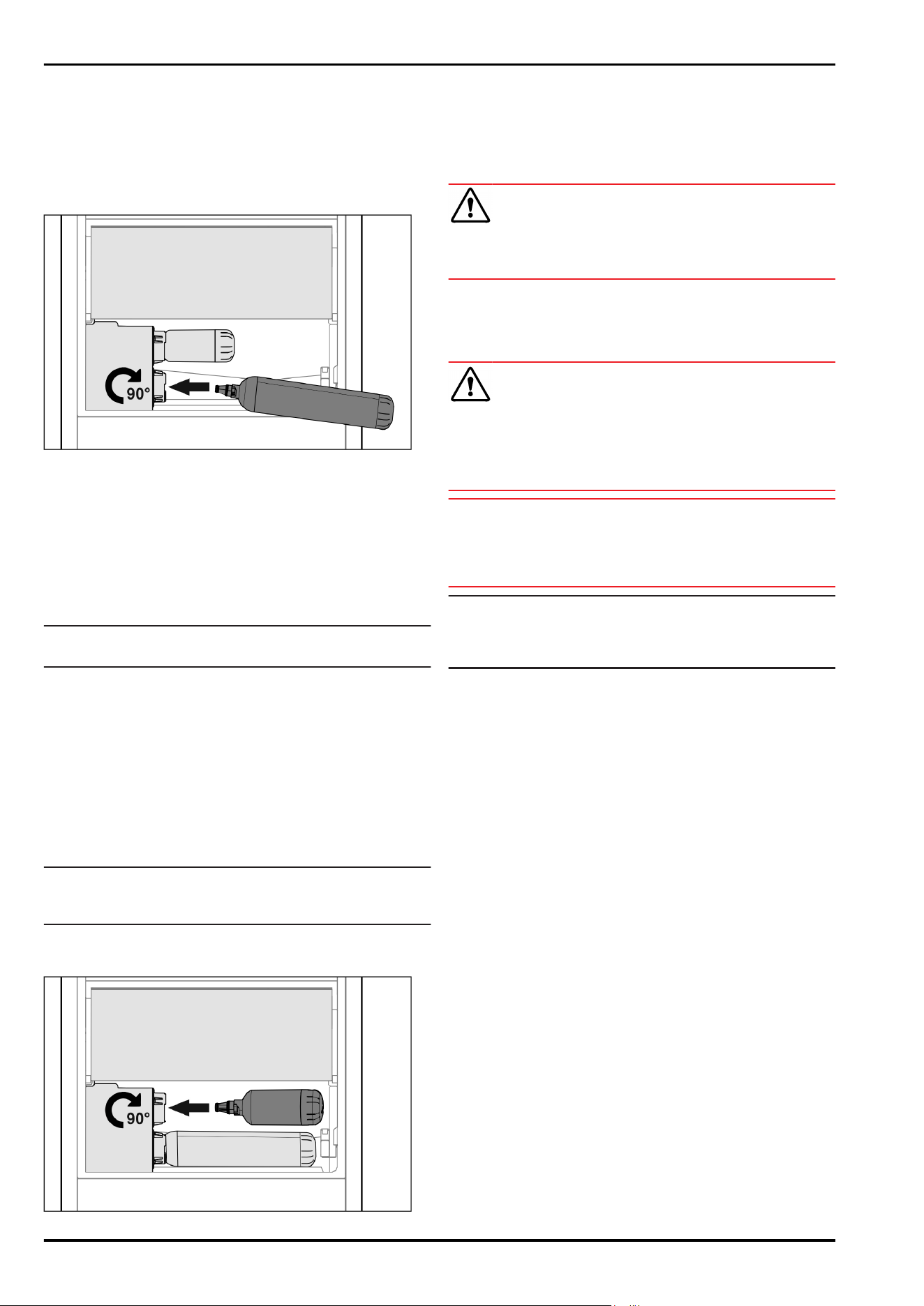
16.1 Inserting the water filter
Fig.54
u
Remove the drawer compartment.
u
Insert the water filter and rotate approx. 90° clockwise
until it clicks in.
u
Check that the filter is sealed and no water leaks out.
u
Insert the drawer compartment.
CAUTION
New water filters can contain suspended matter.
u
Draw 3 l of water from the InfinitySpring and dispose of
it.
w
The water filter is now ready for use.
17 Connecting device
WARNING
Danger of fire due to incorrect connection!
Burns.
Damage to the appliance.
u
Do not use an extension cable.
u
Do not use distributor blocks.
NOTICE
Danger of damage to incorrect connection!
Damage to the appliance.
u
Do not connect the appliance to a stand-alone inverter,
e.g. solar power systems and petrol generators.
Note
Only use the supplied mains cable.
u
A longer mains cable can be ordered from Customer
Service.
Ensure that the following conditions are met:
- The type of current and voltage at the installation site
match the information on the serial tag .
- The socket is earthed according to the regulations and
fused.
- The fuse tripping current is between 10 and 16A.
- The socket is easily accessible.
- The socket is not located behind the appliance but in
areas a or b(a, b, c).
u
Check the electrical connection.
u
Insert the appliance plug (G) into the back of the appli‐
ance. Ensure that they latch into place.
u
Connect the mains plug to the power supply.
w
The Liebherr logo appears on the screen.
w
The display switches to the standby symbol.
Water tank
* Depending on model and options 21

home.liebherr.com/fridge-manuals
fridge/freezer
Issue date: 20240215
Part number index: 7086361-00
Liebherr-Hausgeräte Marica EOOD
Bezirk Plovdiv
4202 Radinovo
Bulgarien