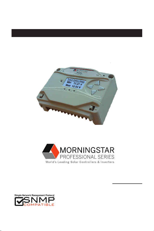
Solar Charging System Controller
Installation, Operation, and Maintenance Manual
www.morningstarcorp.com
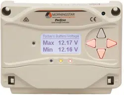
ProStar
TM
MODELS
PS-15
PS-30
PS-15M
PS-30M
ProStar Operator’s Manual
iii
TABLE OF CONTENTS
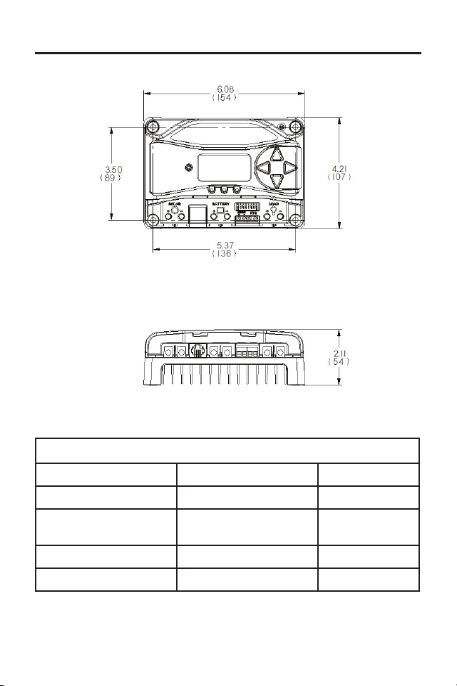
DIMENSIONS [inches (millimeters)]
1.0 Important Safety Instructions
........................
1
2.0
General Information
.....................................
13
2.1
Overview
.........................................................
13
2.2 Regulatory Information
...............................
14
2.3 Features
...........................................................16
2.4 Optional Accessories
......................................18
3.0 Installation
.....................................................
21
3.1 General Installation Notes
............................
21
3.2 Configuration
........................................... 23
3.3 Mounting
................................................. 26
3.4 Wiring
...................................................... 27
3.4.1 Wire Sizing....................................................27
3.4.2 Required Overcurrent Protection
Devices (OCPDs) and Disconnects..............30
3.4.3 Wiring Connections.....................................35
4.0 Operation.................................................47
4.1 Battery Charging Information.....................47
4.2 Load Control Information...................................60
4.3 LED Indications.................................................. 62
4.3.1 Power-up............................................................ 62
4.3.2 Status LED..........................................................62
4.3.3 State-of-charge LEDs......................................... 63
4.4 Push-button Use in Non-Metered Versions......64
4.5 Custom Settings........ ...................................... 65
4.5.1 Programming with Meter Display..................... 65
(Cont.)
SPECIFICATION SUMMARY
PS-15 / PS-15M PS-30 / PS-30M
Nominal Battery voltage 12 or 24V 12 or 24V
Max. PV Open- Circuit
Voltage*
30 or 60V 30 or 60V
Max. Battery Charging Current 15A 30A
Rated Load Current 15A 30A
*Array voltage should never exceed this limit

ProStar Operator’s Manual
iii
TABLE OF CONTENTS
DIMENSIONS [inches (millimeters)]
1.0 Important Safety Instructions
........................
1
2.0
General Information
.....................................
13
2.1
Overview
.........................................................
13
2.2 Regulatory Information
...............................
14
2.3 Features
...........................................................16
2.4 Optional Accessories
......................................18
3.0 Installation
.....................................................
21
3.1 General Installation Notes
............................
21
3.2 Configuration
........................................... 23
3.3 Mounting
................................................. 26
3.4 Wiring
...................................................... 27
3.4.1 Wire Sizing....................................................27
3.4.2 Required Overcurrent Protection
Devices (OCPDs) and Disconnects..............30
3.4.3 Wiring Connections.....................................35
4.0 Operation.................................................47
4.1 Battery Charging Information.....................47
4.2 Load Control Information...................................60
4.3 LED Indications.................................................. 62
4.3.1 Power-up............................................................ 62
4.3.2 Status LED..........................................................62
4.3.3 State-of-charge LEDs......................................... 63
4.4 Push-button Use in Non-Metered Versions......64
4.5 Custom Settings........ ...................................... 65
4.5.1 Programming with Meter Display..................... 65
(Cont.)
SPECIFICATION SUMMARY
PS-15 / PS-15M PS-30 / PS-30M
Nominal Battery voltage 12 or 24V 12 or 24V
Max. PV Open- Circuit
Voltage*
30 or 60V 30 or 60V
Max. Battery Charging Current 15A 30A
Rated Load Current 15A 30A
*Array voltage should never exceed this limit

1
iv
ProStar Operator’s ManualImportant Safety Instructions
1.0
TABLE OF CONTENTS (Cont.)
4.5.2 Programming in MSView...................................67
4.5.3 Meter Display Operation...................................67
4.5.3.1 Directional Key Use and Operation /
Navigating the Meter Map........................... 67
4.5.3.2 Adjusting the Meter Display..........................68
4.5.4 Using the Meter Display to Program Charging
Set-points, Load Control, Communications,
and Advanced Settings.................................68
4.5.5 Lighting Control - Programming Overview...... 68
4.5.6 Lighting Programming Using Meter Display.... 69
4.5.7 Low-Temperature Foldback..............................70
4.6 Inspection and Maintenance............................ 71
5.0 Troubleshooting............................................. 73
5.1 Alarms...............................................................73
5.2 LED Fault Indications........................................74
5.3 Battery Charging and Performance Issues.......79
6.0 Warranty and Policies................................... 81
7.0 Technical Specifications................................ 84
Appendix A - De-rating.......................................... 88
Appendix B - Wire Sizing....................................... 88
CERTIFICATION ADDENDUM
TO OPERATOR’S MANUAL
SAVE THESE INSTRUCTIONS.
This manual contains important safety, installation,
operating and maintenance instructions for the ProStar
solar controller.
The following symbols are used throughout this manual
to indicate potentially dangerous conditions or mark
important safety instructions:
WARNING: Indicates a potentially dangerous
condition. Use extreme caution when performing
this task.
CAUTION: Indicates a critical procedure for safe
and proper operation of the controller.
NOTE: Indicates a procedure or function that is
important to the safe and proper operation of the
controller.
CONSIGNES IMPORTANTES DE SÉCURITÉ
CONSERVEZ CES INSTRUCTIONS:
Ce manuel contient des instructions importantes de
sécurité, d’installations et d’utilisation du contrôleur
solaire ProStar.
Les symboles suivants sont utilisés dans ce manuel pour
indiquer des conditions potentiellement dangereuses ou
1.0 IMPORTANT SAFETY INSTRUCTIONS
3
2
ProStar Operator’s ManualImportant Safety Instructions
1.0
WARNING: THE COMMUNICATIONS
PORT IS CONSIDERED TO BE DVC B. AN
EXTERNAL ISOLATOR IS REQUIRED IF IT IS
TO BE CONNECTED TO A DVC A CIRCUIT.
• External solar and battery disconnects are required.
• Disconnect all sources of power to the controller
before installing or adjusting the ProStar.
• There are no fuses or disconnects inside the ProStar
Do not attempt to repair.
Informations de Sécurité
• Lisez toutes les instructions et les avertissements
figurant dans le manuel avant de commencer
l’installation.
• Le ProStar ne contient aucune pièce réparable
par l’utilisateur. Ne démontez pas ni ne tentez de
réparer le contrôleur.
AVERTISSEMENT: Risque De Choc
Électrique.
NON ALIMENTATION OU AUX BORNES
D'ACCESSOIRES SONT ISOLÉS ÉLECTRIQUEMENT
DE L'ENTRÉE DE C.C ET DOIT ÊTRE ALIMENTÉS
À UNE TENSION DANGEREUSE SOLAIRE. SOUS
CERTAINES CONDITIONS DE DÉFAILLANCE, LA BAT-
TERIE POURRAIT DEVENIR TROP CHARGÉE. TEST
ENTRE TOUTES LES BORNES ET LA MASSE AVANT
DE TOUCHER.
AVERTISSEMENT: LE PORT DE
COMMUNICATION EST CONSIDÉRÉE
COMME DVC B. UN ISOLATEUR EXTERNE
N'EST NÉCES SAIRE SI C'EST D'ÊTRE CONNECTÉ À
des consignes importantes de sécurité.
AVERTISSEMENT : Indique une condition
potentiellement dangereuse. Faites preuve
d’une prudence extrême lors de la réalisation
de cette tâche.
PRUDENCE : Indique une procédure critique
pour l’utilisation sûre et correcte du
contrôleur.
REMARQUE : Indique une procédure ou
fonction importante pour l’utilisation sûre et
correcte du contrôleur.
Safety Information
• Read all of the instructions and cautions in the
manual before beginning installation.
• There are no user serviceable parts inside the
ProStar. Do not disassemble or attempt to repair
the controller.
WARNING: Risk Of Electrical Shock.
NO POWER OR ACCESSORY TERMINALS
ARE ELECTRICALLY ISOLATED FROM DC INPUT,
AND MAY BE ENERGIZED WITH HAZARDOUS SOLAR
VOLTAGE. UNDER CERTAIN FAULT CONDITIONS,
BATTERY COULD BECOME OVER-CHARGED. TEST
BETWEEN ALL TERMINALS AND GROUND BEFORE
TOUCHING.
5
4
ProStar Operator’s ManualImportant Safety Instructions
1.0
UN DVC UN CIRCUIT.
• External solaire et la batterie se déconnecte sont
nécessaires.
• Déconnectez toutes les sources d’alimentation du
contrôleur avant d’installer ou de régler le ProStar.
• Le ProStar ne contient aucun fusible ou interrupteur.
Ne tentez pas de réparer.
• Installez des fusibles/coupe-circuits externes selon
le besoin.
Installation Safety Precautions
WARNING: This unit is not provided
with a GFDI device. This charge
controller must be used with an external
GFDI device as required by the Article
690 of the National Electrical Code for
the installation location.
• Mount the ProStar indoors. Prevent exposure to
the elements and do not allow water to enter the
controller.
• Install the ProStar in a location that prevents casual
contact. The ProStar heatsink can become very hot
during operation.
• Use insulated tools when working with batteries.
• Avoid wearing jewelry during installation.
• The battery bank must be comprised of batteries of
same type, make, and age.
• UL/IEC 62109 certified for use in negative ground or
floating systems only.
• Do not smoke near the battery bank.
• Power connections must remain tight to avoid
excessive heating from a loose connection.
• Use properly sized conductors and circuit
interrupters.
• The grounding terminal is located in the case, and
is identified by the symbol below:
Ground Symbol
• This charge controller is to be connected to DC
circuits only. These DC connections are identified
by the symbol below:
Direct Current Symbol
7
6
ProStar Operator’s ManualImportant Safety Instructions
1.0
The ProStar controller must be installed by a qualified
technician in accordance with the electrical regulations
of the country of installation.
A means of disconnecting all power supply poles must
be provided. These disconnects must be incorporated
in the fixed wiring.
The ProStar negative power terminals are common,
and must be grounded as instructions, local codes,
and regulations require.
A permanent, reliable earth ground must be estab-
lished with connection to the ProStar ground terminal.
The grounding conductor must be secured against any
accidental detachment.
Précautions de Sécurité D’installation
AVERTISSEMENT: L’appareil n’est pas
fourni avec un dispositif GFDI. Ce
contrôleur de charge doit être utilisé
avec un dispositif GFDI externe comme
requis par le code local ou les
réglementations
• Montez le ProStar à l’intérieur. Empêchez
l’exposition aux éléments et la pénétration d’eau
dans le contrôleur.
• Installez le ProStar dans un endroit qui empêche
le contact occasionnel. Le dissipateur de chaleur
ProStar peut devenir très chaud pendant le fonc-
tionnement.
• Utilisez des outils isolés pour travailler avec les
batteries.
• Évitez le port de bijoux pendant l’installation.
• Le groupe de batteries doit être constitué de
batteries du même type, fabricant et âge.
• UL/IEC 62109 certifié pour utilisation au négatif à la
masse ou les systèmes flottants seulement.
• Ne fumez pas à proximité du groupe de batteries.
• Les connexions d’alimentation doivent rester
serrées pour éviter une surchauffe excessive d’une
connexion desserrée.
• Utilisez des conducteurs et des coupe-circuits de
dimensions adaptées.
• La borne de mise à la terre se trouve dans l'affaire
et est identifié par le symbole ci-dessous :
• Ce contrôleur de charge ne doit être connecté qu’à
des circuits en courant continu. Ces connexions CC
sont identifiées par le symbole ci-dessous:
Le régulateur ProStar doit être installé par un tech-
nicien qualifié conformément aux règlements du pays
9
8
ProStar Operator’s ManualImportant Safety Instructions
1.0
d'installation électriques.
Un moyen de déconnexion de tous les poteaux
d'alimentation doit être fourni. Ceux-ci se déconnecte
doit être intégrée dans le câblage fixe.
Une mise à la terre permanent et fiable s'impose avec
raccordement à la borne ProStar.
Les bornes de puissance négative ProStar sont
communs et doivent être mise à la terre comme les
directives, les codes locaux, et les règlements exigent.
Le conducteur de terre doit être protégée contre tout
détachement accidentel.
Battery Safety
WARNING: A battery can present a risk
of electrical shock or burn from large
amounts of short-circuit current, fire, or
explosion from vented gases. Observe proper
precautions.
AVERTISSEMENT : Une batterie peut
présenter a risque de choc électrique
ou de brûlure de grandes quantités de
court-circuit curlouer, incendie ou explosion de ventilé
gaz. Observer précautions appropriées.
WARNING: Risk of Explosion.
Proper disposal of batteries is
required.
Do not dispose of batteries in fire. Refer to local
regulations or codes for requirements.
AVERTISSEMENT : Risque d'Explosion.
Au rebut des piles est nécessaire. Ne
pas jeter les piles dans le feu. Se référer
aux réglementations locales ou des codes pour les
exigences.
CAUTION: When replacing batteries,
use properly specified number, sizes, types,
and ratings based on application and system de-
sign.
PRUDENCE: Lorsque le remplacement des
piles, utilisez correctement nombre spécifié,
tailles, types et les évaluations basées sur conception
de système et d'application.
CAUTION: Do not open or mutilate
batteries. Released electrolyte is harmful
to skin, and may be toxic.
PRUDENCE: Ne pas ouvrir ou mutiler les
piles. L'électrolyte est nocif pour la peau et
peut être toxique.
• Servicing of batteries should be performed, or
supervised, by personnel knowledgeable about
batteries, and the
proper safety precautions.
• Be very careful when working with large lead-acid
batteries. Wear eye protection and have fresh water
available in case there is contact with the battery
acid.
• Remove watches, rings, jewelry and other metal
objects before working with batteries.
• Wear rubber gloves and boots

11
10
ProStar Operator’s ManualImportant Safety Instructions
1.0
• Use tools with insulated handles and avoid placing
tools or metal objects on top of batteries.
• Disconnect charging source prior to connecting or
disconnecting battery terminals.
• Determine if battery is inadvertently grounded.
If so, remove the source of contact with ground.
Contact with any part of a grounded battery can
result in electrical shock. The likelihood of such
a shock can be reduced if battery grounds are
removed during installation and maint enance
(applicable to equipment and remote battery
supplies not having a grounded supply circuit).
• Carefully read the battery manufacturer's
instructions before installing / connecting to, or
removing batteries from, the ProStar.
• Be very careful not to short circuit the cables
connected to the battery.
• Have someone nearby to assist in case of an
accident.
• Explosive battery gases can be present during
charging. Be
certain there is enough ventilation to
release the gases.
• Never smoke in the battery area.
• If battery acid comes into contact with the skin,
wash with
soap and water. If the acid contacts
the eye, flood with fresh water and get medical
attention.
• Be sure the battery electrolyte level is correct before
starting charging. Do not attempt to charge a frozen
battery.
• Recycle the battery when it is replaced.
• Entretien des batteries devrait être effectué ou su-
pervisé, par un personnel bien informé sur les piles
et les précautions de sécurité appropriées.
• Soyez très prudent quand vous travaillez avec des
grandes batteries au plomb. Portez des lunettes de
protection et ayez de l’eau fraîche à disposition en
cas de contact avec l’électrolyte.
• Enlevez les montres, bagues, bijoux et autres ob-
jets mé talliques avant de travailler avec des piles.
• Porter des bottes et des gants de caoutchouc
• Utiliser des outils avec poignées isolantes et évitez
de placer des outils ou des objets métalliques sur le
dessus de batteries.
• Débrancher la source de charge avant de brancher
ou dis-reliant les bornes de la batterie.
• Utilisez des outils isolés et évitez de placer des
objets métalliques dans la zone de travail.

ProStar Operator’s Manual 13
2.0
12
Important Safety Instructions
• Déterminer si batterie repose par inadvertance.
Dans l'affirmative, supprimer la source du contact
avec le sol. Contact avec n'importe quelle partie
d'une batterie mise à la terre peut entraîner un choc
électrique. La probabilité d'un tel choc peut être
réduite si des motifs de batterie sont supprimés
pendant l'installation et maintentretien (applicable
à l'équipement et les fournitures de pile de la télé-
commande n'ayant ne pas un circuit d'alimentation
mise à la terre).
• Lisez attentivement les instructions du fabricant de
la batterie avant d'installer / connexion à ou retrait
des batteries du ProStar.
• Veillez à ne pas court-circuiter les câbles connectés
à la batterie.
• Ayez une personne à proximité qui puisse aider en
cas d’accident.
• Des gaz explosifs de batterie peuvent être présents
pendant la charge. Assurez-vous qu’une ventilation
suffisante évacue les gaz.
• Ne fumez jamais dans la zone des batteries
• En cas de contact de l’électrolyte avec la peau,
lavez avec du savon et de l’eau. En cas de contact
de l’électrolyte avec les yeux, rincez abondamment
avec de l’eau fraîche et consultez un médecin.
• Assurez-vous que le niveau d’électrolyte de la bat-
terie est correct avant de commencer la charge. Ne
tentez pas de charger une batterie gelée.
• Recyclez la batterie quand elle est remplacée.
2.1 Overview
Thank you for choosing the ProStar solar charge
controller.
The ProStar battery charging process has been
optimized for long battery life and improved system
performance. Self-diagnostics and electronic error
protections prevent damage when installation
mistakes or system faults occur. The controller also
features eight (8) adjustable settings switches, a
communication port, and terminals for remote battery
temperature and voltage measurement.
Please take the time to read this operator’s manual
to become familiar the many benefits the ProStar can
provide for your PV systems, for example:
• Rated for 12 or 24 Volt systems, and 15 or 30 Amps
of charging current
• Fully protected with automatic and manual recovery
• Seven standard charging programs selectable with
DIP switches
• Continuous self-testing with fault notification
• LED indications and optional meter monitoring
• Terminals sized for #14-6 AWG (2.5-13.3 mm
2
) wire
• Includes battery voltage sense terminals
• Optional remote battery temperature sensor
• 5-year warranty (see Section 6.0)
2.0 GENERAL INFORMATION

General Information
ProStar Operator’s Manual
15
14
2.0
2.2 Regulatory Information
NOTE: This section contains
important information on
regulatory requirements.
ProStar controllers comply with the
following European (ENs) standards:
• Immunity: EN 61000-4-3: 2006
EN 61000- 4-6: 2009
• Immunity:
EN 61000-6-2: 2005/AC:2005 EMC
• Emissions:
EN 61000-6-4: 2007 +A1:2011 EMC
FCC Requirements:
This device complies with Part 15 of the
FCC rules. Operation is subject to the
following two conditions: (1) This device
may not cause harmful interference, and,
(2) this device must accept any interference
received, including interference that may
cause undesired operation.
Changes or modifications not expressly
approved by Morningstar, for compliance,
could void the user’s authority to operate
the equipment.
NOTE: This equipment has been tested
and found to comply with the limits for a
Class B digital device, pursuant to Part 15 of the
FCC
rules. These limits are designed to provide reasonable
protection against harmful interference in a residential
installation. This equipment generates, uses, and can
radiate radio frequency energy and, if not installed and
used in accordance with the instruction manual, may
cause harmful interference to radio communication.
However, there is no guarantee that interference will not
occur in a particular installation. If this equipment does
cause harmful interference to radio or television
reception, which can be determined by turning the
equipment on and off, the user is encouraged to try to
correct the interference by one or more of the following
measures:
• Re-orient or relocate the receiving antenna.
• Increase the separation between the equipment
and receiver.
• Connect the equipment into an outlet on a
circuit different from that to which the receiver is
connected.
• Consult the dealer, or an experienced radio/TV
technician for help.
This Class B digital apparatus complies with Canadian
ICES-003.
General Information
ProStar Operator’s Manual
17
16
2.0
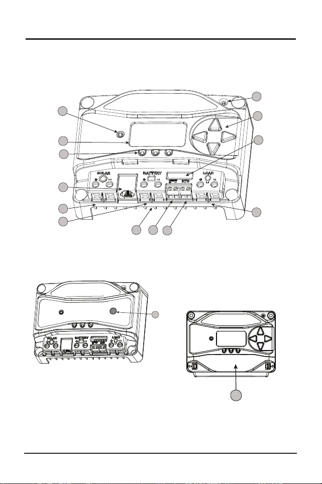
Figure 2.1. ProStar Features
Figure 2.3. Removable
Terminal Cover
2.3 Features
The features of the ProStar are shown in Figures 2-1,
2.2 and 2.3 below. An explanation of each feature
follows.
12
12
12
10
4
2
12
3
1
8
9
5
11
6
7
13
14
15
Figure 2.2. Non-Metered
Unit Push-Button
1 - Charging Status / Error LED
Shows charging current and error condition statuses.
2 - Heatsink
Aluminum heatsink (underneath) to dissipate
controller heat (the ProStar is 100% passively cooled
for reliability)
3 - Meter Display (optional)
Digital LCD monitoring and programming display
4 - Battery Status / Fault LED Indicators
Three state of charge (SOC) LED indicators show
charging status and controller faults
5 - Solar Positive and Negative Terminals
Power connections for Solar (+) and (-) cable
terminations
6 - Battery Positive and Negative Terminals
Power connections for Battery (+) and (-) cable
terminations
7 - Load Positive and Negative Terminals
Power connections for Load (+) and (-) cable
terminations
8 - Local Temperature Sensor
Compensates charging based on ambient
temperature, in absence of Remote Temperature
Sensor
9 - Meter Directional Buttons
Used to navigate throughout the meter map
10 - DIP Switches
Eight (8) settings switches to configure operation of
the ProStar

General Information
ProStar Operator’s Manual
17
16
2.0
Figure 2.1. ProStar Features
Figure 2.3. Removable
Terminal Cover
2.3 Features
The features of the ProStar are shown in Figures 2-1,
2.2 and 2.3 below. An explanation of each feature
follows.
12
12
12
10
4
2
12
3
1
8
9
5
11
6
7
13
14
15
Figure 2.2. Non-Metered
Unit Push-Button
1 - Charging Status / Error LED
Shows charging current and error condition statuses.
2 - Heatsink
Aluminum heatsink (underneath) to dissipate
controller heat (the ProStar is 100% passively cooled
for reliability)
3 - Meter Display (optional)
Digital LCD monitoring and programming display
4 - Battery Status / Fault LED Indicators
Three state of charge (SOC) LED indicators show
charging status and controller faults
5 - Solar Positive and Negative Terminals
Power connections for Solar (+) and (-) cable
terminations
6 - Battery Positive and Negative Terminals
Power connections for Battery (+) and (-) cable
terminations
7 - Load Positive and Negative Terminals
Power connections for Load (+) and (-) cable
terminations
8 - Local Temperature Sensor
Compensates charging based on ambient
temperature, in absence of Remote Temperature
Sensor
9 - Meter Directional Buttons
Used to navigate throughout the meter map
10 - DIP Switches
Eight (8) settings switches to configure operation of
the ProStar

General Information
ProStar Operator’s Manual
19
18
2.0
11 - MeterBus
TM
Port
RJ-11 socket for Morningstar MeterBus
TM
network
connections
12 - Battery Sense Terminals
Connection points for battery voltage sensing wires
13 - Remote Temperature Sensor Terminals (RTS)
Connection points for a Morningstar RTS to remotely
monitor battery temperature
14 - Push-button (non-metered version)
Initiates manual Equalization, clears any faults or
reminders, conducts a lighting test, restores settings
to factory default
15 - Removable Terminal Cover
Cover protects circuit board and termination points
2.4 Optional Accessories
The following accessories are available for purchase
separately from your authorized Morningstar dealer:
Remote Temperature Sensor (Model: RTS)
The RTS measures battery temperature for accurate
temperature compensation and is recommended
when the ambient battery temperature differs from the
ambient controller temperature by +/- 5º C or more.
An RTS can be attached to the ProStar at any time.
The ProStar will automatically use the RTS for battery
temperature compensation when installed. The stan
-
dard cable length is 33 ft (10m), and can be extended
to 100 ft (30m) if required. Installation instructions are
provided with the RTS.
NOTE: The use of a Remote Temperature
Sensor (RTS) is strongly recommended.
Controller location, air flow, and system power can
drastically affect the local temperature sensor reading.
An RTS will provide optimal charging performance.
RM-1 Meter
A remote meter for monitoring system variables,
for use through the ProStar Meterbus port.
Ground-fault Protection Device (GFPD-150V)
The GFPD-150V detects power source ground faults
and interrupts current as required by the US National
Electrical Code.
Communications Support:
Ethernet MeterBus Converter (EMC-1)
This product is an Ethernet gateway that provides
web monitoring services, a Modbus TCP/IP server,
and a local web page server. End users can collect
information about their off-grid PV system remotely.
One EMC-1 supports all products with MeterBus
ports by bridging MODBUS TCP/IP requests to serve
LiveView pages for each product.
USB Communications Adapter (UMC-1)
A modular unit that uses a USB-B plug, usually
from a USB A-B computer cable, and an RJ-11
plug to connect with a Morningstar controller’s
MeterBus port, for monitoring and programming
using MSView PC software.

ProStar Operator’s Manual 21
3.0
General Information
20
PC MeterBus Adapter
TM
(Model: MSC)
The MSC converts the MeterBus RJ-11 electrical
interface to an isolated standard RS-232 interface
which enables communication between the
ProStar and a PC.
The MSC can be used for
programming custom charging set-points, and for
logging data in MSView. See Section 4.5 for more
information on programming.
3.0 INSTALLATION INSTRUCTIONS
3.1 General Installation Notes
• Read through the entire installation section first
before beginning installation.
• Do not install in locations where water can enter
the controller.
• Loose power connections and/or corroded wires
may result in resistive connections that melt wire
insulation, burn surrounding materials, or even
cause fire. Ensure tight connections and use cable
clamps to secure cables and prevent them from
swaying in mobile applications.
CAUTION: Equipment Damage
When installing the ProStar in an enclosure, ensure
sufficient ventilation. Installation in a sealed enclosure may
lead to over-heating and a decreased product lifetime.
PRUDENCE : Dommages à l'équipement
Assurez une ventilation suffisante en cas d’installation
du ProStar dans une enceinte. L'installation dans une
enceinte hermétique peut entraîner une surchauffe et une
réduction de la durée de vie du produit.
• Preset charging profiles are generally designed for
lead acid batteries. Custom settings can be used
for varied charging requirements (see sections 3.2
and 4.5 for details). Note that some battery types
may not be compatible.
• The ProStar battery connection may be wired to
one battery or a bank of batteries. The following
instructions refer to a singular battery,
Installation
ProStar Operator’s Manual
23
22
3.0
but it is implied that the battery connection can be
made to either one battery or a group of batteries in a
battery bank.
• The ProStar uses stainless steel fasteners, an
anodized aluminum heat sink, and conformal
coating to protect it from harsh conditions.
However, for acceptable service life, extreme
temperatures and marine environments should be
avoided.
• The ProStar prevents reverse current leakage at
night, so a blocking diode is not required in the
system.
• The ProStar is designed to regulate ONLY solar
(photovoltaic) power. Connection to any other type
of power source e.g. wind turbine or generator may
void the warranty. However, other power sources
may be connected directly to the battery.
• The connector terminals will accept a maximum
wire size of AWG #6 / 13.3 mm
2
(multi-strand). Use
an insulated flathead screwdriver, and torque tightly
up to 35 in-lb (4 N-m).
CAUTION:
For hazardous location-IECEx/ATEX applications,
see the addendum - part no. MS-003245-EN -
to this manual.
PRUDENCE:
Pour les applications en environnement dangereux -
IECEx / ATEX, voir l'addendum - référence MS-
003245-FR - à ce Manuel.
WARNING: Shock and Fire Hazard
Battery, load and PV array disconnects and overcurrent
protection are required in the system. These protection devices
are external to the ProStar PWM controller.
AVERTISSEMENT : Risque d'électrocution et d'incendie
Des déconnexions de batterie, de charge et de générateur
photovoltaïque et une protection contre les surintensités sont
nécessaires dans le système. Ces dispositifs de protection sont
externes au contrôleur ProStar PWM.
WARNING: Shock and Fire Hazard
All breakers must be properly sized based on maximum
circuit current.
AVERTISSEMENT : Risque d'électrocution et d'incendie
Tous les disjoncteurs doivent être correctement
dimensionnés en fonction du courant maximal du circuit.
WARNING: Shock and Fire Hazard
Minimum over-current protection device interrupt ratings
must be 2000A for 12V systems, and 4000A for 24V systems.
AVERTISSEMENT : Risque d'électrocution et d'incendie
Les valeurs nominales minimales d'interruption du disposi-
tif de protection contre les surintensités doivent être de 2 000 A
pour les systèmes 12 V et de 4 000 A pour les systèmes 24 V.
NOTE: Carefully observe the LEDs after each connection.
The LEDs will indicate proper polarity, and a secure
co nnection.
3.2 Configuration
The DIP switch block shown in Figure 3.1 below is used
to set the operating parameters for the ProStar.
Installation
ProStar Operator’s Manual
25
24
3.0
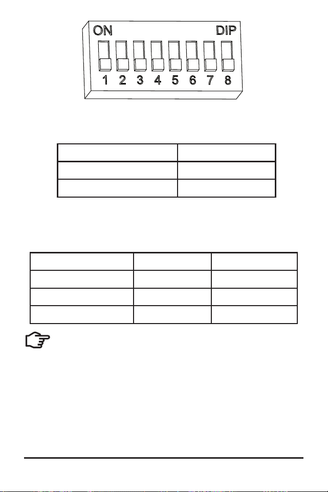
Figure 3.1. DIP Switch Block to set charging parameters
Switch 1: Load / Lighting
Mode Switch 1
Normal OFF
Lighting ON
Switches 2, 3: System Voltage
Three (3) system voltage configurations are available
as shown in the table below:
System voltage Switch 2 Switch 3
Auto OFF OFF
12 OFF ON
24 ON OFF
NOTE: Before connecting the battery, measure
the open-circuit voltage. It must be over 10
Volts to start the controller. If the system voltage
DIP Settings Switches are set to Auto-detect, battery
voltage over 15.5V will be detected as a 24V nominal
battery, and the unit will charge accordingly. The
12/24V auto selection is only done at start-up, and
the detected system voltage will never change during
operation.
It is recommended to set DIPs 2 and 3 to the correct
system voltage setting. Only use the default auto-
detect setting if the nominal system voltage is not
known.
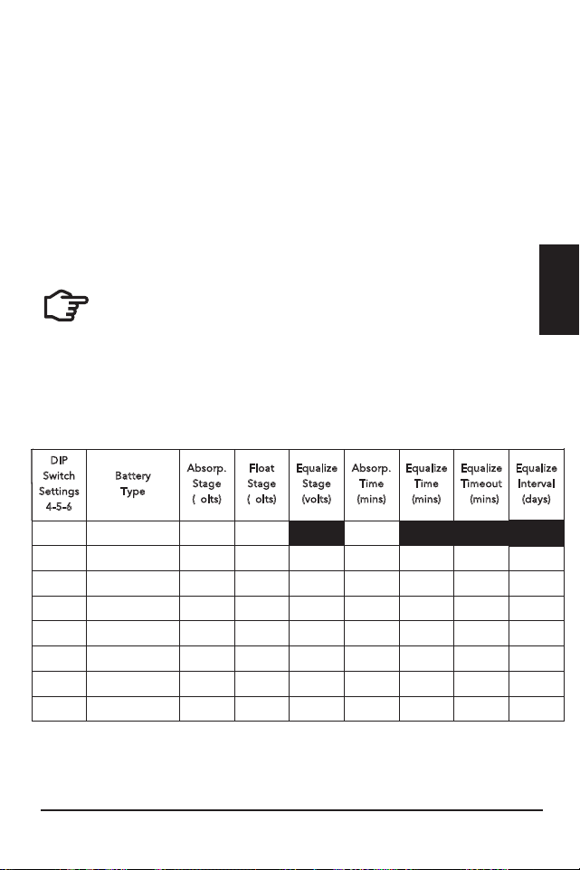
Switches 4, 5, 6: Battery Type Selection
Preset ProStar battery charging options are shown
in table 3-1 below. All voltage settings listed are for
nominal 12 Volt batteries. Multiply the voltage settings
by two (2) for 24 Volt systems.
NOTE: The charging profiles below are general
guidelines for use at the operator’s discretion. Consult
the battery manufacturer for optimal battery charge
settings.
Battery Charging Set-points (@ 25°C):
[multiply voltages by (2) for 24 Volt systems]
DIP
Switch
S
ettings
4
-5-6
B
attery
T
ype
A
bsorp.
S
tage
(
volts)
F
loat
S
tage
(
volts)
E
qualize
S
tage
(
volts)
A
bsorp.
T
ime
(
mins)
E
qualize
T
ime
(
mins)
E
qualize
T
imeout
(
mins)
E
qualize
I
nterval
(
days)
off-off-off
1 - Sealed*
14.00
13.50
150
off-off-on
2 - Sealed*
14.15
13.50
14.40
150
60
120
28
off-on-off
3 - Sealed*
14.30
13.50
14.60
150
60
120
28
off-on-on
4- AGM/Flooded
14.40
13.50
15.10
180
120
180
28
on-off-off
5 - Flooded
14.60
13.50
15.30
180
120
180
28
on-off-on
6 - Flooded
14.70
13.50
15.40
180
180
240
28
on-on-off
7 - L-16
15.40
13.40
16.00
180
180
240
14
on-on-on
8 - Custom
Custom
Custom
Custom
Custom
Custom
Custom
Custom
* “Sealed” ba�ery type includes gel and AGM ba�eries
Installation
ProStar Operator’s Manual
25
24
3.0
Figure 3.1. DIP Switch Block to set charging parameters
Switch 1: Load / Lighting
Mode Switch 1
Normal OFF
Lighting ON
Switches 2, 3: System Voltage
Three (3) system voltage configurations are available
as shown in the table below:
System voltage Switch 2 Switch 3
Auto OFF OFF
12 OFF ON
24 ON OFF
NOTE: Before connecting the battery, measure
the open-circuit voltage. It must be over 10
Volts to start the controller. If the system voltage
DIP Settings Switches are set to Auto-detect, battery
voltage over 15.5V will be detected as a 24V nominal
battery, and the unit will charge accordingly. The
12/24V auto selection is only done at start-up, and
the detected system voltage will never change during
operation.
It is recommended to set DIPs 2 and 3 to the correct
system voltage setting. Only use the default auto-
detect setting if the nominal system voltage is not
known.
Switches 4, 5, 6: Battery Type Selection
Preset ProStar battery charging options are shown
in table 3-1 below. All voltage settings listed are for
nominal 12 Volt batteries. Multiply the voltage settings
by two (2) for 24 Volt systems.
NOTE: The charging profiles below are general
guidelines for use at the operator’s discretion. Consult
the battery manufacturer for optimal battery charge
settings.
Battery Charging Set-points (@ 25°C):
[multiply voltages by (2) for 24 Volt systems]
DIP
Switch
S
ettings
4
-5-6
B
attery
T
ype
A
bsorp.
S
tage
(
volts)
F
loat
S
tage
(
volts)
E
qualize
S
tage
(
volts)
A
bsorp.
T
ime
(
mins)
E
qualize
T
ime
(
mins)
E
qualize
T
imeout
(
mins)
E
qualize
I
nterval
(
days)
off-off-off
1 - Sealed*
14.00
13.50
150
off-off-on
2 - Sealed*
14.15
13.50
14.40
150
60
120
28
off-on-off
3 - Sealed*
14.30
13.50
14.60
150
60
120
28
off-on-on
4- AGM/Flooded
14.40
13.50
15.10
180
120
180
28
on-off-off
5 - Flooded
14.60
13.50
15.30
180
120
180
28
on-off-on
6 - Flooded
14.70
13.50
15.40
180
180
240
28
on-on-off
7 - L-16
15.40
13.40
16.00
180
180
240
14
on-on-on
8 - Custom
Custom
Custom
Custom
Custom
Custom
Custom
Custom
* “Sealed” ba�ery type includes gel and AGM ba�eries
Installation
ProStar Operator’s Manual
27
26
3.0
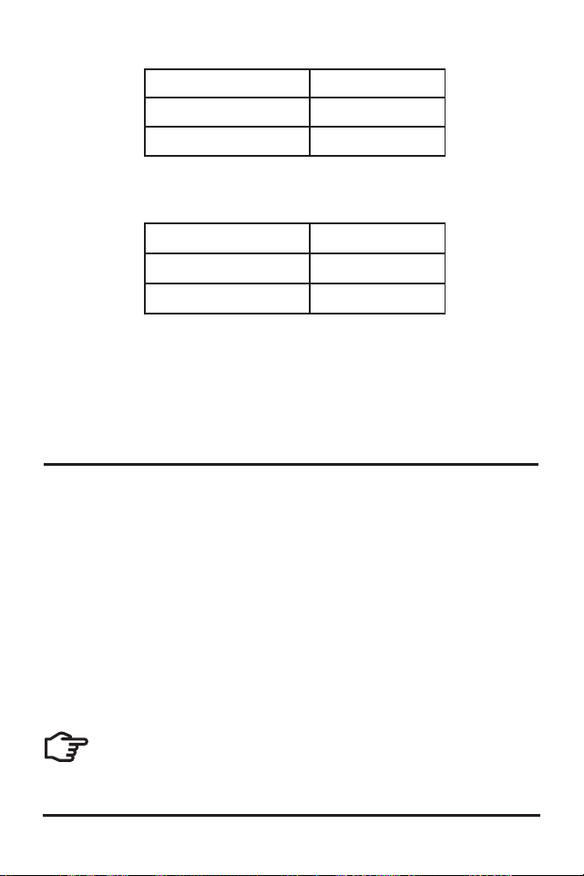
Switch 7: Battery Equalization
Mode Switch 7
Manual Equalization OFF
Auto Equalization ON
Switch 8: Current Switching
Mode Switch 8
PWM switching OFF
Slow switching ON
The default (PWM) switching setting (OFF / down) operates
at 300Hz. If load or system noise is an issue, DIP 8 can be set
(ON-up) for slow switching at 1Hz. Standard PWM switching is
recommended when system noise is not a problem.
3.3 Mounting
Inspect the controller for shipping damage.
Mount the ProStar to a vertical surface (4-#8 stainless
steel self-tapping screws are included). Tighten the
mounting screws using care not to crack the plastic
case.
Do not install directly over an easily combustible
surface since the heat sink may get hot under certain
operating conditions.
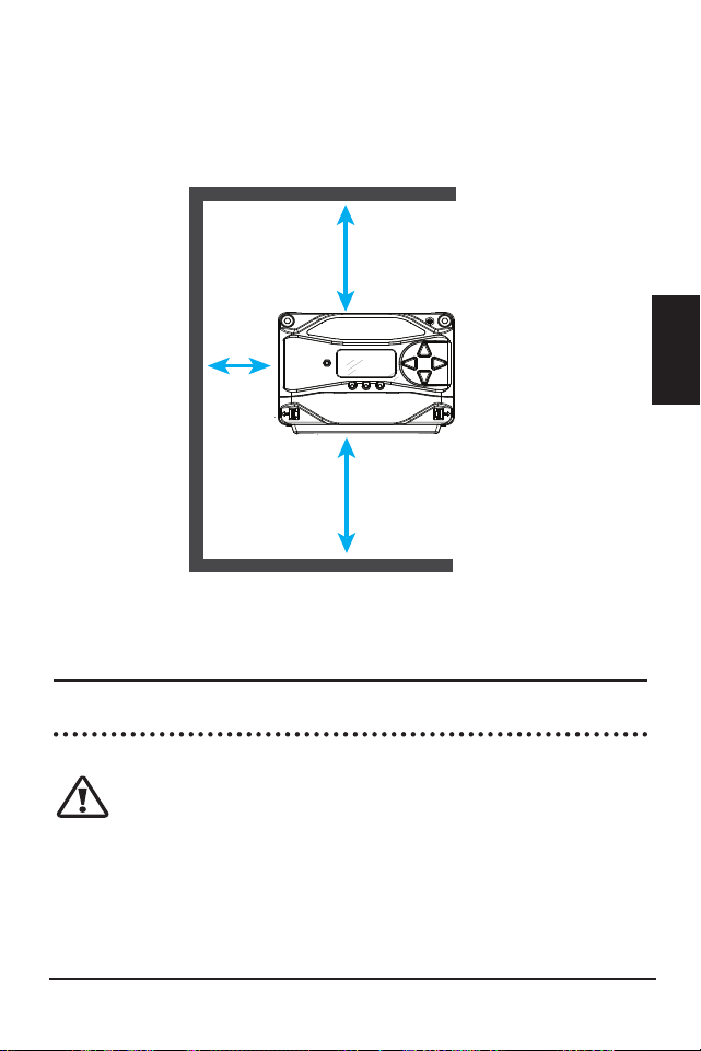
NOTE: The heat sink must be in a vertical
position (fins up and down).
For proper air flow, allow at least 15 cm (6 in) of space
above and below the controller, and 50 mm (2 in) at
the sides - see Figure 3-2 below. Do not locate in an
enclosure where battery gases can accumulate.
Figure 3-2. Proper Clearances for Passive Cooling
3.4 Wiring
3.4.1 Wire Sizing
CAUTION: Code Requirements
U.S. installed wiring must conform to all current
U.S. NEC, ANSI/NFPA 70 requirements, and to any
local regulations. Non-U.S. installations must meet
all national and local requirements of the country of
installation.
6 in / 150 mm
6 in / 150 mm
2 in /
50 mm
Installation
ProStar Operator’s Manual
27
26
3.0
Switch 7: Battery Equalization
Mode Switch 7
Manual Equalization OFF
Auto Equalization ON
Switch 8: Current Switching
Mode Switch 8
PWM switching OFF
Slow switching ON
The default (PWM) switching setting (OFF / down) operates
at 300Hz. If load or system noise is an issue, DIP 8 can be set
(ON-up) for slow switching at 1Hz. Standard PWM switching is
recommended when system noise is not a problem.
3.3 Mounting
Inspect the controller for shipping damage.
Mount the ProStar to a vertical surface (4-#8 stainless
steel self-tapping screws are included). Tighten the
mounting screws using care not to crack the plastic
case.
Do not install directly over an easily combustible
surface since the heat sink may get hot under certain
operating conditions.
NOTE: The heat sink must be in a vertical
position (fins up and down).
For proper air flow, allow at least 15 cm (6 in) of space
above and below the controller, and 50 mm (2 in) at
the sides - see Figure 3-2 below. Do not locate in an
enclosure where battery gases can accumulate.
Figure 3-2. Proper Clearances for Passive Cooling
3.4 Wiring
3.4.1 Wire Sizing
CAUTION: Code Requirements
U.S. installed wiring must conform to all current
U.S. NEC, ANSI/NFPA 70 requirements, and to any
local regulations. Non-U.S. installations must meet
all national and local requirements of the country of
installation.
6 in / 150 mm
6 in / 150 mm
2 in /
50 mm

Installation
ProStar Operator’s Manual
29
28
3.0
PRUDENCE : Exigences du Code
Le câblage installé aux États-Unis doit être conforme
à toutes les exigences actuelles du NEC américain,
ANSI/NFPA 70 et à toute réglementation locale. Non
américain les installations doivent répondre à toutes les
exigences nationales et locales du pays d'installation.
The power terminals are sized for #14 - 6 AWG (2.5
- 13.3 mm
2
) wire. Use an insulated 3/16” (4.76 mm)
flathead screwdriver, and torque tightly up to 35 in-lb
(4 N-m).
The terminals are rated for copper and aluminum
conductors. Use UL-listed Class B or Class C stranded
wire rated for 300 Volt and 75C or higher. Copper
is recommended due to the ease of use, good
conductivity, strength and lower thermal expansion
properties.
It is critical that the ampacity (current carrying
capacity) of conductors is sufficient to allow the
maximum current of the power circuits. The ProStar
power terminals are rated for 75ºC. When wires with a
90°C temperature rating are used with terminals that
have a 75°C temperature rating, wire ampacity at 75°C
must be used. This also applies to the temperature
ratings of breaker and disconnect terminals.
The controller battery and load wire ampacity must be
greater than or equal to 125% of current rating of the
ProStar controller. Minimum battery wire sizes are as
follows:
ProStar-15/M: #12 AWG (4 mm
2
) or #10 AWG
(6 mm
2
) if greater than 50°C inside conduit
ProStar-30/M: #8 AWG (10 mm
2
) or #10 AWG (6 mm
2
)
if greater than 50°C inside conduit.
NOTE: For smaller load breakers or fuses, a smaller
wire size can be used. The minimum wire sizes based
on breaker or fuse current rating are as follows:
#14 AWG with 15A breakers or fuses
#16 AWG with 10A breakers or fuses (less than 8A
maximum continuous current)
#18 AWG with less than 7A breakers or fuses (less than
5.6A maximum continuous current)
The PV input wire ampacity must be greater than or
equal to 156% of PV Array Isc without correction and
adjustment factors, and also greater than or equal to
125% of PV Array Isc after correction and adjustment
factors.
Wire ampacity correction and adjustment factors may
also be required to account for the following:
• temperatures at different parts of the circuit (roof-
tops or engine rooms, for example)
• wire terminal temperature ratings
• multi-conductor cables
• conduit fill and other factors
Good system design generally requires large
conductors/wires that limit voltage drop losses to 2%
or less.
See Appendix B - Voltage Drop (distances) Tables - for
minimum copper wire sizing to achieve maximum 2%
voltage drops.
Installation
ProStar Operator’s Manual
31
30
3.0
WARNING: Fire Hazard
If multiple units are used in parallel for more
charging current, the battery conductor wiring must
be sized for the total sum of all current ratings of the
combined controllers.
AVERTISSEMENT : Risque d'incendie
Si plusieurs unités sont utilisées en parallèle
pour plus de courant de charge, le câblage du con-
ducteur de la batterie doit être dimensionné pour
la somme totale de tous les courants nominaux des
contrôleurs combinés.
3.4.2 Required Overcurrent Protection Devices
(OCPDs) and Disconnect Switches
WARNING: Fire Hazard
Battery, load and PV array overcurrent
protection (breakers or fuses) are required in the
system. These protection devices are external to the
ProStar controller, and must be sized as required
by the US NEC, local or country of installation code
requirements.
AVERTISSEMENT : Risque d'incendie
Surintensité de la batterie, de la charge et du
générateur photovoltaïque protection (disjoncteurs
ou fusibles) sont nécessaires dans le système. Ces
dispositifs de protection sont externes au contrôleur
ProStar et doivent être dimensionnés conformément
aux exigences du NEC ou du code local.
WARNING: Shock Hazard
The PV system requires a means of
disconnecting the battery, load and PV array.
Breaker switches or disconnect switches can serve
as a disconnecting means and should be located at
readily accessible locations. For best practices and
safety guidance see NEC 690 “Part III - Disconnecting
Means” for disconnect requirements for PV systems in
addition to other code requirements.
AVERTISSEMENT : Risque d'électrocution
Le système PV nécessite un moyen de
déconnecter la batterie, la charge et le générateur PV.
Les disjoncteurs ou les sectionneurs peuvent servir
de moyens de déconnexion et doivent être situés à
un endroit facilement accessible. Pour les meilleures
pratiques et les conseils de sécurité, voir NEC 690
"Partie III - Disconnecting Means" pour les exigences
de déconnexion des systèmes PV en plus des autres
exigences du code.
WARNING: Shock Hazard
Fuses, single-pole circuit breakers, or single-
pole disconnect switches must only be installed on
ungrounded system conductors. The NEC allows,
and may require, the use of double-pole breakers or
double-pole disconnect switches which break both the
grounded and ungrounded conductors of the PV array.
AVERTISSEMENT : Risque d'électrocution
Les fusibles, les disjoncteurs unipolaires ou
les sectionneurs unipolaires ne doivent être installés
que sur des conducteurs de système non mis à la
terre. Le NEC autorise et peut exiger l'utilisation de
disjoncteurs bipolaires ou de sectionneurs bipolaires
qui coupent à la fois les conducteurs mis à la terre et
non mis à la terre du générateur photovoltaïque.

Installation
ProStar Operator’s Manual
33
32
3.0
BATTERY DISCONNECT AND OVER-CURRENT
PROTECTION DEVICE SIZING
The U.S. NEC requires the installation of DC breakers
or fused disconnect switches in all battery circuits in
order to provide both a means of disconnection and
overcurrent protection.
The battery breaker or fused disconnect switch(es)
should be located near the battery or the battery
busbar. Where the controller battery terminals are
more than 1.5m (5 feet) from the battery, or where
circuits from these terminals pass through a wall
or partition, U.S. NEC requires that a means of
disconnection be provided at the battery and solar
controller.
The minimum battery disconnect switch current rating
is the current rating of the controller being
installed. To provide over-current protection when
using a disconnect switch, a properly sized fuse or
breaker must be installed in series.
Battery breakers or fuses must be sized with a
minimum of 125% of the continuous output current
rating of the solar controller. Recommended battery
circuit fuse or breaker current ratings:
ProStar-15/M: 20 Amps
ProStar-30/M: 40 Amps
PV INPUT DISCONNECT AND OVER-CURRENT
PROTECTION DEVICE SIZING
WARNING: Shock and Fire Hazards
The solar array open-circuit voltage (Voc) at the
worst-case (coldest) module temperature must
not exceed the PV disconnect or overcurrent
protection voltage ratings.
AVERTISSEMENT : Risques d'électrocution et
d'incendie
La tension en circuit ouvert du générateur solaire (Voc)
à la température de module la plus défavorable (la
plus froide) doit ne pas dépasser les valeurs nominales
de tension de déconnexion PV ou de protection
contre les surintensités.
As defined in NEC Section 690.9, PV input disconnect
switches must have a current rating greater than or
equal to the maximum PV array current (1.25 x PV
array Isc). PV array Isc equals the number of strings
multiplied by the module Isc (STC) rating. Note that
individual PV string circuits do not require disconnects.
NEC Section 690.9 also provides requirements for
over-current protection. The PV input breaker or
fuse current rating should not be less than the next
higher breaker rating above 125% of the maximum PV
array current (156% of the PV array Isc). Maximum PV
breaker or fuse ratings are:
ProStar-15 / M: 20 Amps

Installation
ProStar Operator’s Manual
35
34
3.0
Figure 3-3. Wiring the ProStar
To battery (+) and
(-) terminals for
voltage sensing
To battery for
temperature
sensing
To battery (+)
and (-)
terminals
To load (+)
and (-)
terminals
To properly
sized array
1
7
5
2
3
6
REFER TO FIGURE 3.3 WHEN USING THE
WIRING INSTRUCTIONS BELOW
ProStar-30 / M: 40 Amps
String over-current protection is also required for
parallel strings, and are typically included with the PV
string combiner.
There may be other code requirements specific to the
installation of a particular PV array.
LOAD DISCONNECT AND OVER-CURRENT PROTECTION
DEVICE SIZING
The load output breaker or fused disconnect switch
should be near the load output terminals of the
controller. A load fuse should be installed between the
controller output and the load disconnect.
The load output disconnect switch must have a
minimum current rating greater than or equal to the
fuse current rating but is not required to be higher
than the load output current rating of the controller.
The load fuse or breaker should be sized at a
minimum of 125% of the maximum continuous load
output current. The maximum load output current is
the sum of the branch load circuits or the controller
load output current rating.
The maximum load output breaker or fuse current
rating is:
ProStar-15/M: 20 Amps
ProStar-30/M: 40 Amps
3.4.3 Wiring Connections
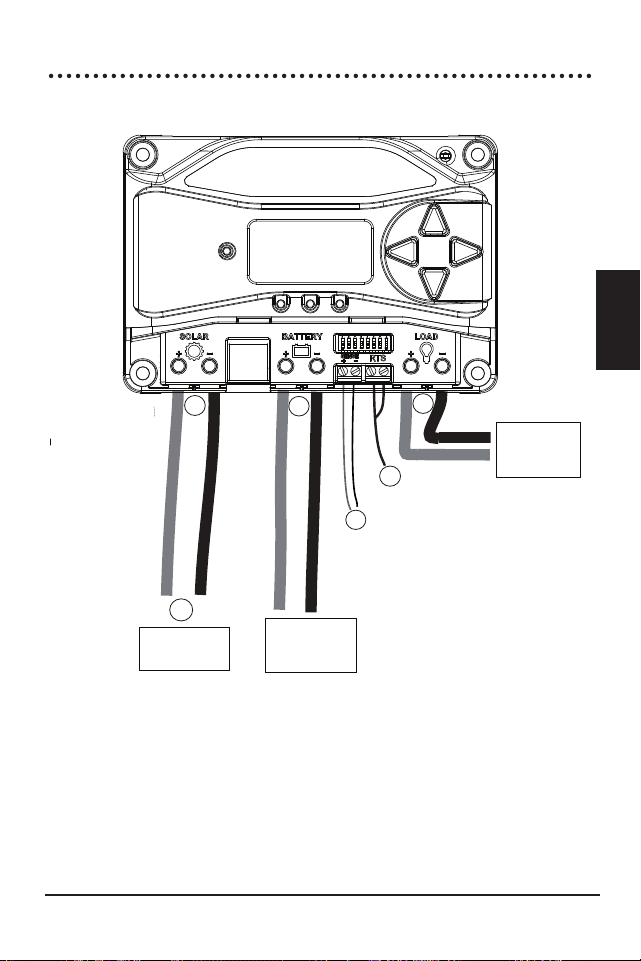
Installation
ProStar Operator’s Manual
37
36
3.0
STEP 1: Check Controller Limitations
Verify that the highest temperature compensated solar
array open-circuit voltage (Voc), and load current do
not exceed the ratings of the ProStar version being
installed.
Multiple controllers can be installed in parallel on the
same battery bank to achieve greater total charging
current. In this type of system, each ProStar must have
its own solar array. The load terminals of multiple
controllers can only be wired together if the total load
draw does not exceed the nameplate current of the
LOWEST rated controller.
STEP 2: Battery Voltage Sense Wires
WARNING: Fire Hazard
When connecting battery sense wires, install a
5 Amp fuse in the (+) sense wire, six inches
from the (+) battery terminal.
AVERTISSEMENT : Risque d'incendie
Lors de la connexion des câbles de détec-
tion de batterie, installez un Fusible de 5 A dans le
fil de détection (+), à six pouces de la borne (+) de la
batterie.
Due to connection and cable resistance, voltage drops
are unavoidable in power cables that carry current,
including the ProStar battery cables. If battery sense
wires are not used, the controller must use the voltage
reading at the controller's battery power terminals
for regulation. This voltage will be higher than the
actual battery bank voltage while charging the battery.
Generally accepted wiring practice is to limit voltage
drops between the charger and the battery to 2%.
Even properly sized wiring with 2% drop can result in
a 0.29 Volt drop for 14.4V charging. Voltage drops
will cause some undercharging of the battery. The
controller will begin Absorption or limit equalization
at a lower battery voltage because the controller
measures a higher voltage at the controller’s terminals
than is the actual battery voltage. For example, if
the controller is programmed to start Absorption at
14.4V, when the controller “sees” 14.4V at its battery
terminals, the true battery voltage would only be
14.1V, if there is a 0.3V drop between the controller
and battery.
Note that the battery sense wires will not power the
controller, and the sense wires will not compensate
for losses in the power wires between the controller
and the battery. The battery sense wires are used to
improve the accuracy of the battery charging.
The two sense wires, can range in size from 1.0 to 0.25
mm
2
(16 to 24 AWG), and should be cut to length as
required to connect the battery to the voltage sense
terminals. A 2-position terminal (see Figure 3.3) is
used for the battery sense connection. A twisted pair
cable is recommended but not required. Use UL rated
300 Volt conductors. The voltage sense wires may be
pulled through conduit with the power conductors.
Observing correct polarity, connect both battery
voltage sense wires to the ProStar at the 2-position
Battery Sense Terminal, and to battery (+) and (-)
Installation
ProStar Operator’s Manual
39
38
3.0
terminals. No damage will occur if the polarity is
reversed, but the controller cannot read a reversed
sense voltage.
Tighten the connector screws to 5 in-lb (0.56 Nm) of
torque.
The maximum length allowed for each battery voltage
sense wire is 98 ft (30m).
Connecting the voltage sense wires to the RTS
terminals will cause an alarm.
NOTE: If the battery input voltage is greater
than 5 Volts different than the Battery Sense,
due to voltage drops or faulty connections, the Battery
Sense input will not be recognized by the ProStar.
A battery voltage sense connection is not required to
operate the ProStar controller, but it is recommended
for best performance.
The battery voltage sense wires enable the ProStar to
measure the voltage at the battery terminals accurately
with no voltage drop.
STEP 3: Remote Temperature Sensor
WARNING: Risk of Fire
If no Remote Temperature Sensor (RTS) is
connected, use the ProStar within 3m (10 ft) of the
batteries. Internal Temperature Compensation will be
used if the RTS is not connected. Use of the RTS is
strongly recommended.
AVERTISSEMENT : Risque d'incendie
Si aucun capteur de température à distance
(RTS) n'est connecté, utilisez le ProStar à moins de 3
m (10 pieds) des piles. La compensation de tempéra-
ture interne sera utilisée si le RTS n'est pas connecté.
L'utilisation du RTS est fortement recommandée.
All charging settings are based on 25°C (77°F). If
the battery temperature varies by 5°C, the charging
setting will change by 0.15 Volts for a 12 Volt battery.
This is a substantial change in the charging of
the battery, and the use of the optional Remote
Temperature Sensor (RTS) is recommended to adjust
charging to the actual battery temperature.
The need for temperature compensation depends
on the temperature variations, battery type, how
the system is used, and other factors. If the battery
appears to be gassing too much or not charging
enough, the RTS can be added at any time after the
system has been installed.
Connect the RTS to the 2-position terminal located to
the left of the (+) Load terminal (see Figure 3.3).
The RTS is supplied with 33 ft (10 m) of 22 AWG (0.34
mm
2
) cable. There is no polarity, so either wire (+ or -)
can be connected to either screw terminal. The RTS
cable may be pulled through conduit along with the
power wires. Tighten the connector screws to 5 in-lb
(0.56 Nm) of torque. Separate installation instructions
are provided inside the RTS bag.
Installation
ProStar Operator’s Manual
41
40
3.0
CAUTION: Equipment Damage
Never place the temperature sensor inside a
battery cell. Both the RTS and the battery
will be damaged.
ATTENTION : Dommages matériels
Ne placez jamais le capteur de température
dans un cellule de batterie. Le RTS et la batterie
sera endommagé.
CAUTION: The ProStar will use the local
temperature sensor for compensation if the
RTS is not used.
PRUDENCE :
Le ProStar utilisera le
capteur de température pour la compensation
si le RTS n'est pas utilisé.
NOTE: The RTS cable may be shortened if
the full length is not needed. Be sure to
re-install the ferrite choke on the end of the RTS if
a length of cable is removed. This choke ensures
compliance with electromagnetic emissions standards.
STEP 4:
Grounding
NOTE: Depending on the country
of installation, conductors identified by the
color green, or a combination of green /yellow, shall
only be used as earthing conductors.
For safety, and effective lightning protection, it is
recommended, and may be locally required, that
the negative conductor of the charging system be
properly grounded. For conductor sizing requirements,
refer to the US National Electrical Code, or applicable
local regulations or code.
WARNING: Risk of Fire
DO NOT bond DC system electrical negative
to earth grounding terminal on the controller. Per
NEC, system negative must be bonded to earth
ground at only one point, and through a GFPD, if
required.
AVERTISSEMENT : Risque d'incendie
NE PAS relier le négatif électrique du système
CC à la borne de mise à la terre du contrôleur. Si
requis par le code ou la réglementation locale, le
négatif du système doit être relié à la terre en un seul
point et via un GFPD.
STEP 5: Battery Connections - see diagram below
Be sure that DIP switches 2 and 3 are set for 12 or 24V,
as described in Section 3.2.
NOTE: Before connecting the battery, measure
the open-circuit voltage. It must be over 10
Volts to start the controller. If the system voltage
Settings Switches are set to Auto-detect, battery
voltage over 15.5V will be detected as a 24V
nominal battery, and the unit will charge accordingly.
The 12/24V auto selection
is only done at start-up.
Install an OPEN battery OCPD, and connect the
battery wires - observing correct polarity - as shown
below.
DO NOT CLOSE THE BATTERY OCPD AT THIS
TIME.
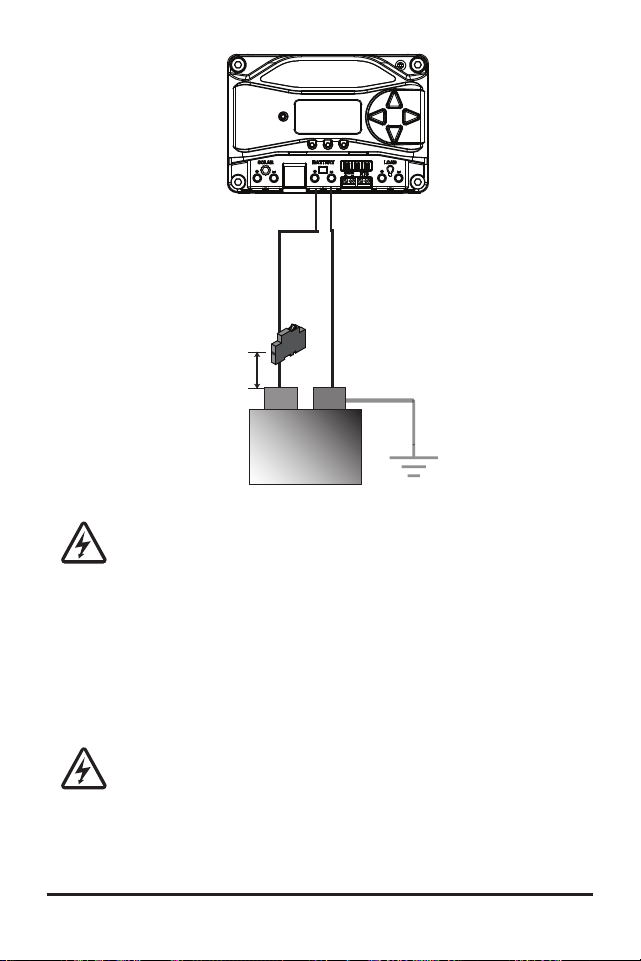
Installation
ProStar Operator’s Manual
43
42
3.0
(at battery
OR solar side,
but NOT both)
System Ground
6 in (150 mm)
Max.
Battery (-)
Battery (+)
+
-
Maximum breaker sizes
are 20 Amps for PS-15/M,
and 40 Amps for PS-30/M
12V or 24V
Battery
WARNING: Shock Hazard
The solar PV array can produce open-
circuit voltages of up to 60 Vdc when in
sunlight, and this DC voltage is supplied to the
Power Conversion Equipment (PCE). Verify that
the solar input breaker or disconnect has been
opened (disconnected) before installing the
system wires.
AVERTISSEMENT : Risque d'électrocution
Le générateur solaire photovoltaïque peut
produire des tensions en circuit ouvert allant jusqu'à
60 Vcc lorsqu'il est exposé au soleil, et cette tension
continue est fournie à l'équipement de conversion
de puissance (PCE). Vérifiez que le disjoncteur ou le
sectionneur d'entrée solaire a été ouvert (déconnecté)
avant d'installer les câbles du système.
STEP 6: Solar Connections - see diagram below
Install an OPEN solar OCPD, and connect the solar
wires - observing correct polarity - as shown below.
Use caution, since the solar array will produce current
whenever in sunlight.
DO NOT CLOSE THE OCPD AT
THIS TIME.
SOLAR (+)
SOLAR (-)
(+)
(
-)
NOTE: For design purposes, array
should be nominal 12V for 12V
battery, and nominal 24V for 24V
battery. Do not exceed 60Voc
Solar
Breaker
Maximum breaker sizes are
20 Amps for PS-15/M, and
40 Amps for PS-30/M
STEP 7: Load Connections
- see diagram below
CAUTION: Equipment Damage
Do not wire any AC inverter to the load
terminals of the ProStar. Damage to the
load control circuit may result. An inverter should be
wired directly to the battery. If there is a possibility that
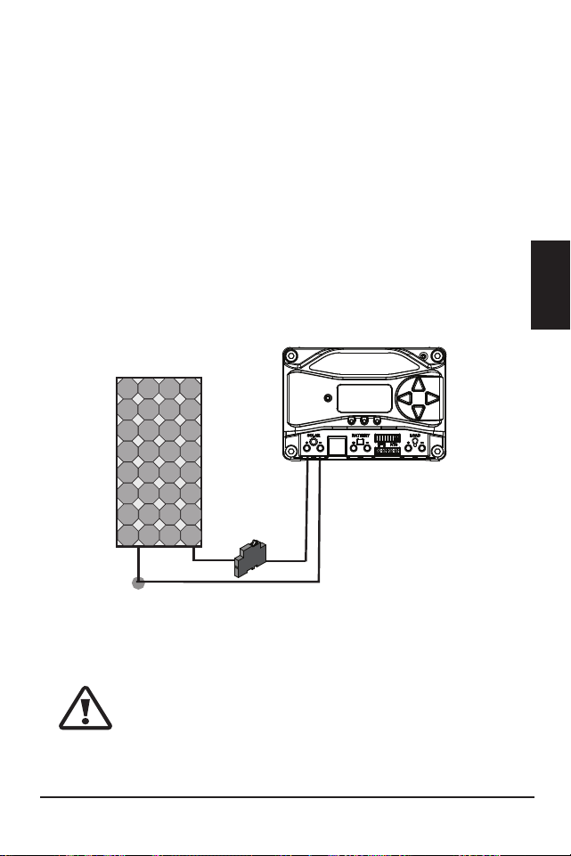

Installation
ProStar Operator’s Manual
45
44
3.0
any other load, e.g., pumps or motors, will sometimes
exceed the Prostar’s maximum voltage or current limits,
the device should be wired directly to the battery/battery
bank. If load control is required, contact Morningstar
Technical Support for assistance.
ATTENTION : Dommages matériels
Ne connectez aucun onduleur CA à la charge
terminaux du ProStar. Cela pourrait endommager le
circuit de commande de charge. Un onduleur doit
être connecté directement à la batterie. S'il y a une
possibilité qu'une autre charge, par ex. pompes
ou moteurs, dépassent parfois la tension maximale
ou les limites de courant du Prostar, l'appareil doit
être connecté directement à la batterie / banque de
batteries. Si un contrôle de charge est nécessaire,
contactez l'assistance technique Morningstar pour
obtenir de l'aide.
With the loads off, install an OPEN load OCPD, and
connect the load wires - observing correct polarity - as
shown below. DO NOT CLOSE THE OCPD AT THIS
TIME.
LOAD (+)
LOAD (-)
Maximum breaker
sizes are 20 Amps
for PS-15/M, and
40 Amps for
PS-30/M
STEP 8: Power-Up and Verify System Operation
Close the battery disconnect to start the processor,
and activate the controller’s protections. Watch the
charging status, and then the three battery state-
of-charge (SOC) LEDs blink in sequence (G-Y-R),
confirming proper start-up. If they do not light, check
the battery polarity (+/–) and battery voltage.
The green, yellow or red LED will light depending on
the battery state-of-charge (SOC). Confirm that one of
these LEDs is on before going to the next step.
Close solar disconnect. If the solar input is connected
while in sunlight, the charging LED indicator will light.
Confirm proper connection by observing the charging
LED.
Insert the load fuse, or close the breaker, and turn the
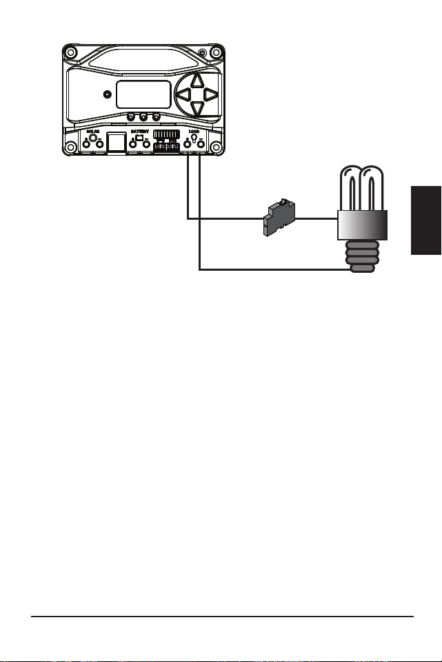
ProStar Operator’s Manual 47
3.0
Operation
46
load on to confirm a proper connection. If the load does
not turn on, it could be for various reasons: the ProStar
is in LVD (red LED on); there is a short circuit in the load
(LEDs blinking R/G – Y); there is an overload condition
(LEDs blinking R/Y - G); the load is not connected, not
working, or turned off. After
all connections have
been completed, observe the LEDs to make sure the
controller is operating normally for system conditions.
If the optional digital meter is used, observe that the
display is scrolling with proper voltage and current
values. Also, a self- test can be performed with digital
meter units.
STEP 9: To Power Down
CAUTION: Risk of Damage
ONLY disconnect the battery from the
ProStar AFTER the solar input has been disconnected.
Damage to the controller may result if the battery is
removed while the ProStar is charging.
ATTENTION : Risque de dommages
Débranchez la batterie du ProStar
UNIQUEMENT APRÈS que l'entrée solaire a été
déconnectée. Le contrôleur peut être endommagé
si la batterie est retirée pendant le chargement du
ProStar.
• To prevent damage, power-down must be done in
the reverse order as power-up.
4.0 OPERATION
4.1 Battery Charging Information
4-Stage Charging
The ProStar has a 4-stage battery charging algorithm
for rapid, efficient, and safe battery charging. Figure
4-1 below shows the sequence of stages.
NIGHT
NIGHT
BULK
CHARGE
ABSORPTION
FLOAT
EQUALIZE
VOLTAGE
TIME
Figure 4-1. ProStar Charging Algorithm
Bulk Charge Stage
During Bulk charging, the battery is not at 100% state
of charge and battery voltage has not yet charged to
the Absorption voltage set-point. The controller will
deliver 100% of available solar power to recharge the
battery.
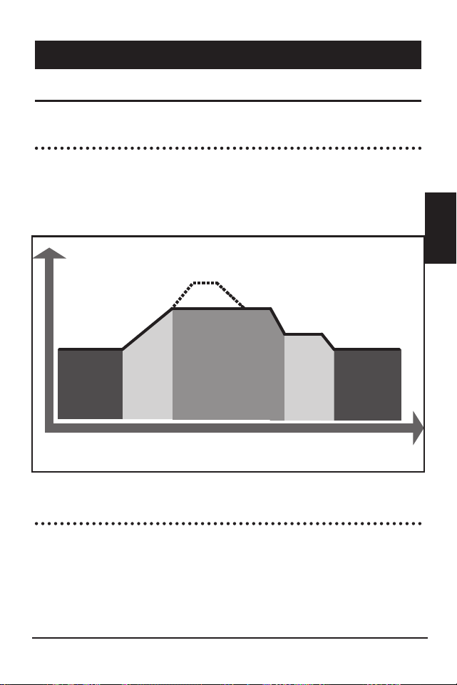

Operation
ProStar Operator’s Manual
49
48
4.0
Absorption Stage
When the battery has recharged to the Absorption
voltage set-point, constant voltage regulation is
used to maintain battery voltage at the Absorption
set-point. This prevents heating and excessive battery
gassing. The battery is allowed to come to full state
of charge at the Absorption voltage set-point. The
green SOC LED will blink once per second during
Absorption charging. The battery must remain in the
Absorption charging stage for a cumulative 150 - 180
minutes, depending on battery type, before transition
to the Float stage will occur. However, Absorption
time will be extended by thirty minutes if the
battery discharges below 12.50 Volts (12V system) the
previous night.
The Absorption set-point is temperature compensated
through either the on-board local temperature sensor,
or an optional Remote Temperature Sensor (RTS).
Float Stage
After the battery is fully charged in the Absorption
stage, the ProStar reduces the battery voltage to
the Float voltage set-point. When the battery is fully
recharged, there can be no more chemical reactions
and all the charging current is turned into heat and
gassing. The float stage provides a very low rate of
maintenance charging while reducing the heating
and gassing of a fully charged battery. The purpose
of float is to protect the battery from long-term
overcharge. The green SOC LED will blink once every
two (2) seconds during Float charging.
Once in Float stage, loads can continue to draw power
from the battery. In the event that the system load(s)
exceed the solar charge current, the controller will
no longer be able to maintain the battery at the Float
set-point. Should the battery voltage remain below the
Float set-point for a cumulative sixty minute period,
the controller will exit Float stage and return to Bulk
charging.
The Float set-point is temperature compensated
through either the on-board local temperature sensor,
or an optional Remote Temperature Sensor (RTS).
Equalization Stage
WARNING: Risk of Explosion
Equalizing vented batteries produces
explosive gases. The battery bank must be properly
ventilated.
Operation
ProStar Operator’s Manual
51
50
4.0
AVERTISSEMENT : Risque d'explosion
L'égalisation des batteries ventilées produit
des gaz explosifs. Le parc de batteries doit être
correctement ventilé.
CAUTION: Equipment Damage
Equalization increases the battery voltage to
levels that may damage sensitive DC loads. Verify
all system loads are rated for the temperature
compensated Equalize voltage before beginning an
Equalization charge.
ATTENTION : Dommages matériels
L'égalisation augmente la tension de la
batterie à des niveaux susceptibles d'endommager
les charges CC sensibles. Vérifiez que toutes les
charges du système sont évaluées pour la tension
d'égalisation compensée en température avant de
commencer une charge d'égalisation.
CAUTION: Equipment Damage
Excessive over-charging and gassing too
vigorously can damage the battery plates and
cause shedding of active material from the plates.
An equalization that is too high, or too long, can
be damaging. Review the requirements for the
particular battery being used in your system.
ATTENTION : Dommages matériels
Une surcharge excessive et un gazage trop
vigoureux peuvent endommager les plaques de
batterie et provoquer une perte de matière active
des plaques. Une égalisation trop élevée ou trop
longue peut être dommageable. Passez en revue les
conditions requises pour la batterie particulière utilisée
dans votre système.
Certain battery types benefit from a periodic boost
charge to stir the electrolyte, level the cell Voltages,
and complete the chemical reactions. Equalization
(EQ) charging raises the battery voltage above the
standard absorption voltage so that the electrolyte
gases. The green SOC LED will blink rapidly two (2)
times per second during equalization charging.
The duration of the equalize charge is determined by
the selected battery type. See table 4-1 in this section
for more details. The Equalization Time is defined
as time spent at the equalize set-point. If there is
insufficient charge current to reach the equalization
voltage, the equalization will terminate after an
additional sixty minutes to avoid over-gassing or
heating of the battery.
If the battery requires more time in equalization, with
non-metered versions, manual EQ can be activated
using the push-button (see Section 4.4) to continue for
one or more additional EQ cycles. The Prostar meter,
or MSView software, can also be used to program EQ
timing and duration.
The Equalization set-point is temperature
compensated through either the on-board local
temperature sensor, or an optional Remote
Temperature Sensor (RTS).

Operation
ProStar Operator’s Manual
53
52
4.0
Why Equalize?
Routine equalization cycles are often vital to the
performance and life of a battery - particularly in a
solar system. During battery discharge, sulfuric acid
is consumed and soft lead sulfate crystals form on the
plates. If the battery remains in a partially discharged
condition, the soft crystals will turn into hard crystals
over time. This process, called “lead sulfation”,
causes the crystals to become harder over time and
more difficult to convert back to soft active materials.
Sulfation from chronic undercharging of the battery is
the leading cause of battery failures in solar systems.
In addition to reducing the battery capacity, sulfate
build-up is the most common cause of buckling
plates and cracked grids. Deep cycle batteries are
particularly susceptible to lead sulfation.
Normal charging of the battery can convert the
sulfate back to the soft active material if the battery
is fully recharged. However, a solar battery is seldom
completely recharged, so the soft lead sulfate crystals
harden over a period of time. Only a long controlled
overcharge, or equalization, at a higher voltage can
reverse the hardening of sulfate crystals.
When to Equalize?
The ideal frequency of equalizations depends on
the battery type (lead-calcium, lead-antimony, etc.),
the depth of discharging, battery age, temperature,
and other factors. One very broad guide is to
equalize flooded batteries every one to three
months or every five to ten deep discharges. Some
batteries, such as the L-16 group, will need more
frequent equalizations.
The difference between the highest cell and
lowest cell in a battery can also indicate the need for
an equalization. Either the specific gravity or the cell
voltage can be measured. The battery manufacturer
can recommend the specific gravity or voltage values
for your particular battery.
Preparation for Equalization
First, confirm that all of the system loads are rated for
the equalization voltage.
Consider that at 0°C (32°F) the Equalization
voltage will reach 16.75 Volts for L-16 batteries with a
temperature sensor installed.
Disconnect any loads at risk of damage due to the
high input voltage.
If Hydrocaps are used, be sure to remove them before
starting an equalization. Replace the Hydrocaps with
standard battery cell caps. The Hydrocaps can get
very hot during an equalization. After the equalization
is finished, add distilled water to each cell to replace
gassing losses. Confirm that the battery plates are
submerged.
Equalize a Sealed Battery?
The Battery Charging Settings table (see table 4-1
below, in this section) shows two sealed battery

Operation
ProStar Operator’s Manual
55
54
4.0
settings with an Equalization cycles. These are
minimal "boost” cycles to level individual cells. This is
not an equalization, and will not vent gas from sealed
batteries that require up to 14.4V charging (12V
battery).
Many VRLA batteries, including AGM and gel,
have charging requirements up to 14.4V (12V
battery). Depending on the battery manufacturer’s
recommendation, the “boost” cycle for sealed cells
can be disabled by setting the equalize setting switch
to manual, if required.
Battery Charge Settings
The ProStar provides seven (7) standard battery
charging settings that are selected with the settings
switches (see Table 4.1 above).
These standard charging settings are suitable for
lead-acid batteries ranging from sealed (gel, AGM,
maintenance-free) to Flooded and L-16 cells. In
addition, an eighth charging setting provides for
custom set-points using MSView
TM
PC software. Table
4-1 below summarizes the major parameters of the
standard charging settings. The shared settings in
Table 4-2 are common to all battery types.
NOTE: These settings are general guidelines for
use at the operator’s discretion.
Consult the battery
manufacturer for optimal battery charge settings.
Battery Charging Set-points (@ 25°C):
[multiply voltages by (2) for 24 Volt systems]
Shared Settings Value Units
Absorption Extension voltage 12.50 Volts
Absorption Extension Time Absorption Time + 30 Minutes
Float Exit Time-out 30 Minutes
Float Cancel voltage 12.10 Volts
Equalize Time-out Equalize Time + 60 Minutes
Temperature Compensation Coefficient - 30
Millivolts
/ °C /
12V
Table 4.2. Battery settings that are shared between all
battery types
DIP
Switch
S
ettings
4
-5-6
B
attery
T
ype
A
bsorp.
S
tage
(
volts)
F
loat
S
tage
(
volts)
E
qualize
S
tage
(
volts)
A
bsorp.
T
ime
(
mins)
E
qualize
T
ime
(
mins)
E
qualize
T
imeout
(
mins)
E
qualize
I
nterval
(
days)
off-off-off
1 - Sealed*
14.00
13.50
150
off-off-on
2 - Sealed*
14.15
13.50
14.40
150
60
120
28
off-on-off
3 - Sealed*
14.30
13.50
14.60
150
60
120
28
off-on-on
4- AGM/Flooded
14.40
13.50
15.10
180
120
180
28
on-off-off
5 - Flooded
14.60
13.50
15.30
180
120
180
28
on-off-on
6 - Flooded
14.70
13.50
15.40
180
180
240
28
on-on-off
7 - L-16
15.40
13.40
16.00
180
180
240
14
on-on-on
8 - Custom
Custom
Custom
Custom
Custom
Custom
Custom
Custom
* “Sealed” ba�ery type includes gel and AGM ba�eries
Table 4-1. Charging parameters for each selectable
battery type
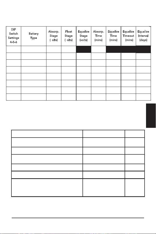
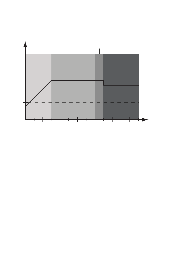
Operation
ProStar Operator’s Manual
57
56
4.0
Absorption Extension
1:00 2:00 3:00 4:00 5:00 6:00
12.50 V
Bulk
Extended
Absorption
FloatAbsorption
Absorption Extension Voltage
time (hrs)
Figure 4-2. Absorption Extension Charging Profile
If battery voltage discharges below 12.50 Volts (25.00
Volts @ 24V) the previous night, Absorption charging
will be extended on the next charge cycle as shown in
figure 4-2 above. Thirty minutes will be added to the
normal Absorption duration.
Float Time-out
1:00 2:00 3:00 4:00 5:00 6:00
Float V
Bulk
Float
Sub-
Float
Absorption
Absorption
60 mins.
below Float
time (hrs)
Bulk
Figure 4-3. Float Exit Time-out Charging Profile
After entering Float stage, the controller will only
exit Float if the battery voltage remains below Float
voltage for sixty cumulative minutes. In figure 4-3, a
system load turns on at 3:30 hrs when the controller
is in Float stage, runs for one hour, and turns off at
4:30 hrs. The load current draw is larger than the
charge current, causing battery voltage to drop below
Float voltage for sixty minutes. The time-out causes
the controller to return to Bulk charging, and then
Absorption stage again. In this example, a load runs
continuously for sixty minutes.
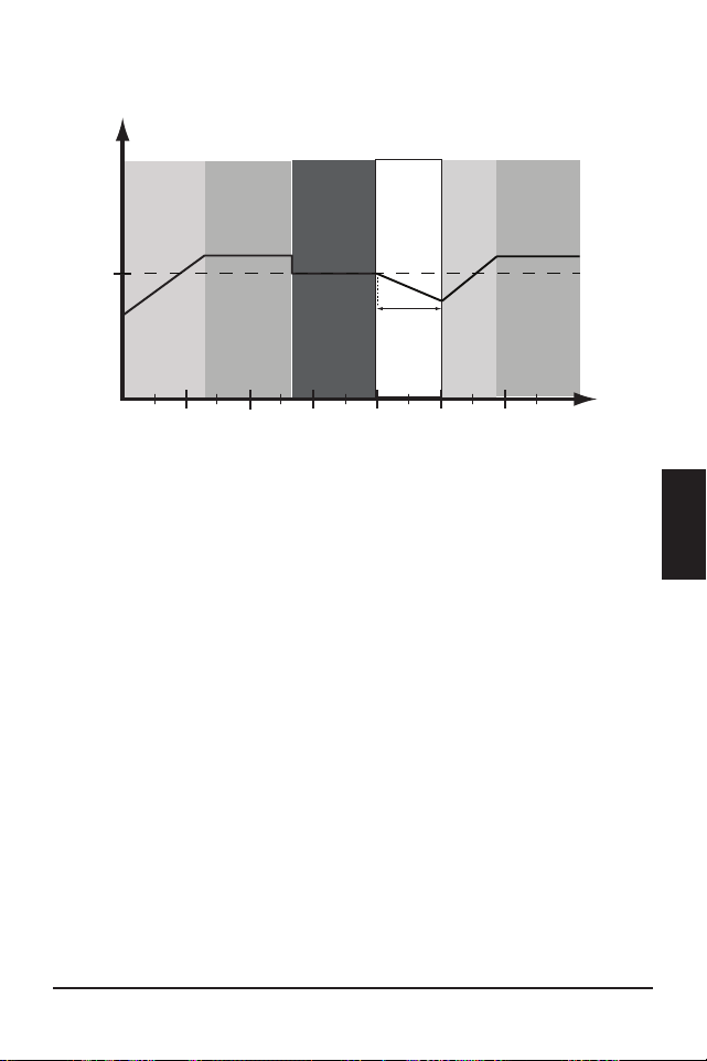
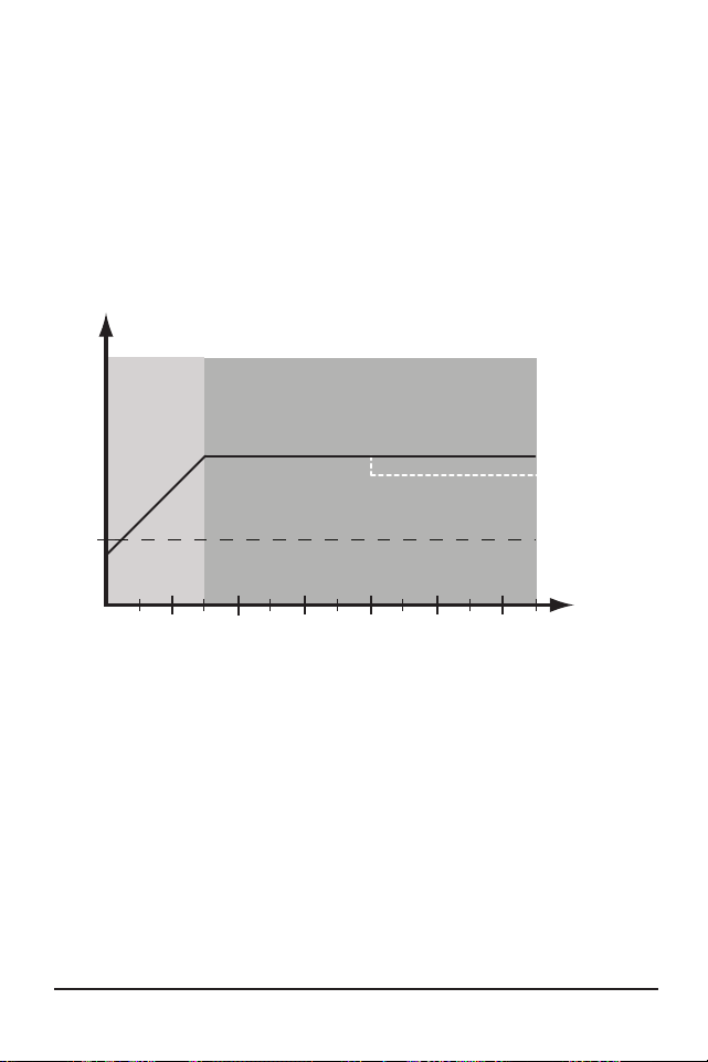
Operation
ProStar Operator’s Manual
59
58
4.0
However, because the Float exit timer is cumulative,
multiple momentary load events that pull the battery
voltage below Float voltage for a combined sixty
minute duration will also force an exit from Float
stage.
Float Cancel voltage
Figure 4.4. Float Cancellation Charging Profile
1:00 2:00 3:00 4:00 5:00 6:00
12.0 V
Bulk
Absorption
Float Cancel Voltage
time (hrs)
Float cancelled this charge cycle
If the battery bank discharges below 12.10 Volts (24.20
Volts @ 24V) the previous night, Float charging stage
will be cancelled for the next charge cycle. Figure 4-4
above, illustrates this concept. At 0:00 hrs (dawn),
battery voltage is below the Float Cancel threshold
voltage. The diagram shows where Float stage would
have occurred if Float was not cancelled.
Equalize Time-out
1:00 2:00 3:00 4:00 5:00 6:00
Absorp. V
Bulk
Float
Equalize
Equalize timeout
time (hrs)
Equalize V
Figure 4.5. Equalize time-out charging profile
The charging profile in figure 4-5 above, shows an
Equalize Time-out event. The time-out timer begins
as soon as battery voltage exceeds the Absorption
voltage set-point. If there is insufficient charging
current or system loads are too large, the battery
voltage may not reach the Equalize set-point. To
avoid battery damage, The Equalize Time-out safety
feature prevents high battery voltage for extended
periods of time.
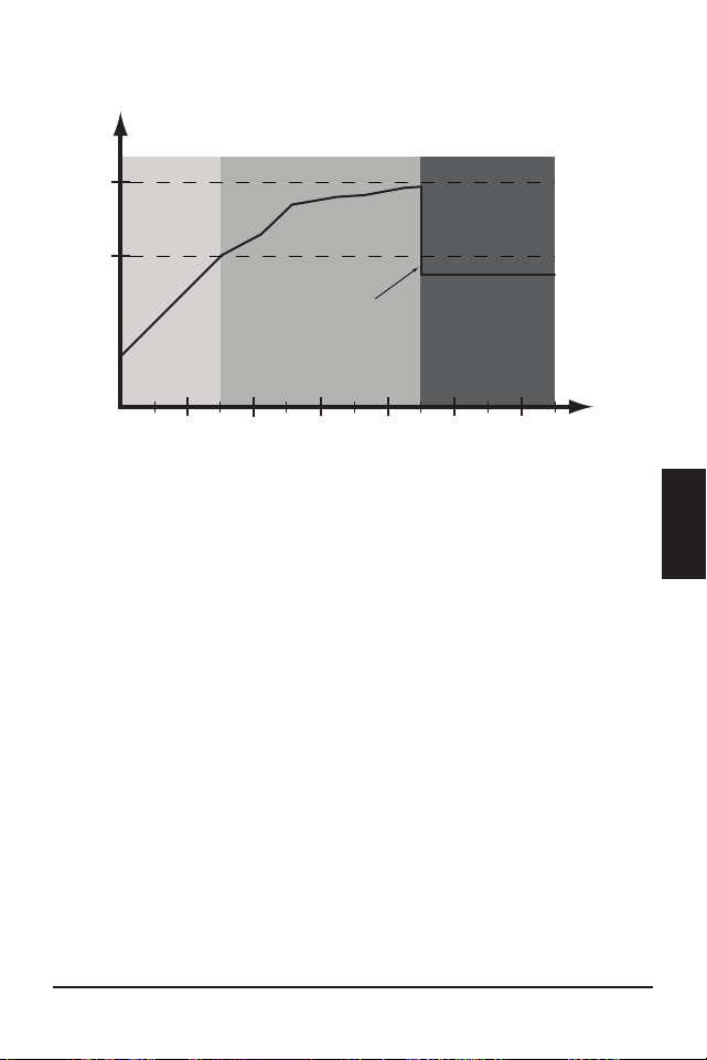

Operation
ProStar Operator’s Manual
61
60
4.0
4.2 Load Control Information
The primary purpose of the load control function
is to disconnect system loads when the battery has
discharged to a low state of charge, and reconnect
system loads when the battery is sufficiently
recharged. The total current draw of all loads must
not exceed the ProStar 15 or 30 Amp maximum load
rating.
Current Compensation:
All LVD and LVR set-points are current compensated.
Under load, the battery voltage will sag in proportion
to the current draw of the load. A short-term large
load could cause a premature LVD without the current
compensation feature. LVD and LVR set-points are
adjusted lower per the following table:
System voltage
Current Compensation
12 Volt -20 mV per Amp of load
24 Volt -40 mV per Amp of load
Table 4-3. LVD and LVR Current Compensation Values
LVD Warning:
As the battery discharges the Battery Status LEDs will
transition from green to yellow and then from yellow
to flashing red. The flashing red indication is a warning
that a low voltage disconnect event will occur soon.
The amount of time between a green SOC
indication and load disconnect will depend on many
factors including:
• rate of discharge - based on amount of load
current
• capacity of the battery
• health of the battery
• LVD set-point
If the battery discharges to the LVD set-point the load
will disconnect and a solid red Battery Status LED
indication will be displayed.
General Load Control Notes:
Do not wire multiple ProStar load outputs together
in parallel to power DC loads with a current draw
greater than 15 or 30A, depending on the ProStar
model. Equal current sharing cannot be assured and
an over-load condition will likely occur on one or more
controllers.
Exercise caution when connecting loads with specific
polarity to a live load circuit. A reverse polarity
connection may damage the load. Always double
check load connections before applying power.

Operation
ProStar Operator’s Manual
63
62
4.0
4.3 LED Indications
KEY:
G = green G - Y - R = flashing sequentially
Y = yellow G / Y = flashing together
R = red G / Y - R = G and Y flashing together,
alternating with R flash
4.3.1. Power-up
Normal power-up: Status LED flashes G, then SOC
LEDS flash G - Y - R, then SOC LEDs indicate battery
charge status with a single battery status LED.
Failed bootload: Status LED flashes G, then SOC
LEDS flash G - Y and stop on solid Y.
4.3.2 Status LED
The Status LED indicates charging status and any
existing solar input error conditions. The Status LED is
on when charging during the day and off at night. The
Status LED will flash red whenever an error condition(s)
exists. Table 4.4 below, lists the Status LED indications.
Color Indication Operating State
None Off (with heartbeat¹) Night
Green
On Solid
( with heartbeat² )
Charging
Red Flashing Error
Red
On Solid
( with heartbeat
2
)
Critical Error
1. Heartbeat indication flickers the Status LED on briefly
every 5 seconds
2. Heartbeat indication flickers the Status LED off briefly
every 5 seconds
Table 4.4. Status LED Definitions
NOTES:
1) R flashing is generally a user addressable fault /
error
2) R charging status LED ON with heartbeat blink OFF
every 5 secs is a critical fault that generally requires
service. See, “Solid Charging Status LED with Self-
test (R-Y-G) SOC Faults”, in Section 5.2.
4.3.3 State-of-Charge LEDs
Battery SOC LED Indications are shown in Table 4-5
below:

Operation
ProStar Operator’s Manual
65
64
4.0
Condition Indication
Absorption G flash - every sec
Float
G flash - every 2 secs
Start Equalization (push-button)
[G / Y / R] x2 - G- G
Stop Equalization (push-button)
[G / Y / R] x2 - R - R
Equalize
G flash - 2 / sec
SOC > 13.5V
G solid
13.5V > SOC > 13.0V
G / Y solid
13.0V > SOC > 12.5V
Y solid
SOC < 12.5V
Y / R solid
Low voltage disconnect warning
R flash - every sec
Low voltage disconnect
R solid
Table 4.5. Battery SOC LED Indications
4.4 Push-Button Use in Non-Metered Versions
The non-metered version of the ProStar features a
push-button that operates as follows depending on
the DIP Switch 1 setting:
Normal Mode (DIP 1 OFF), (operation effective with
firmware v6.0 and higher)
A quick press of the push-button will toggle the load
voltage between ON and OFF.
• The load will not toggle ON-OFF when the unit is
in LVD.
• Regardless of the DIP 7 setting, press and hold the
push-button for five seconds to initiate or stop an
Equalization (EQ).
Lighting Control Mode (DIP 1 ON)
A quick press will then conduct a ten minute lighting
test. A lighting test is used to verify correct wiring
in the load circuit, and/or verify that the lighting
components are operational. A lighting test will
override LVD for ten minutes - the override duration is
not programmable.
• Press and hold the push-button for five seconds to
initiate or stop an EQ.
Reset ProStar to Factory Settings
To restore factory settings: Disconnect PV; disconnect
battery power; press and hold down the push-button;
re-start the ProStar by connecting the battery; keep
the push-button depressed for 3-5 secs, until the
battery LEDs start to cycle R-Y-G.
A Custom Settings Edit fault will occur - see Section 5
for details. The unit will then need to be re-powered
to resume normal operation.
4.5 Custom Settings
4.5.1 Programming with the Meter Display
The ProStar is available in metered and non-metered
versions. The metered model allows:
• custom programming, including lighting programs,
directly from the unit.
• extensive settings adjustment and information as
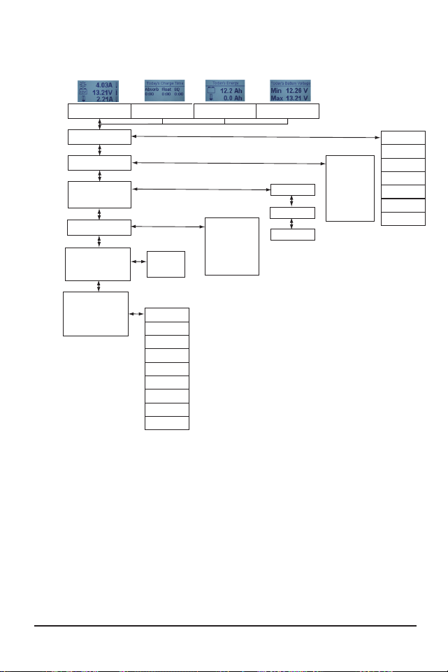
Operation
ProStar Operator’s Manual
67
66
4.0
shown partially in Figure 4-6 below.
Figure 4-6. Simplified Meter Map. For metered models, see
the included complete meter map insert, also available in
the ProStar support documents at:
http://www.morningstarcorp.com
Start Lighting Test
Load Disconnect
Factory Reset
Reset Control
Backlight Timer
Backlight
Target Voltage
Battery Temp.
Display Screens and Programming
Models:
PS-30M
PS-15M
Main Screens
Daily Charging Stage - Time
Daily Charge Transferred -
Battery and Load
Solar Current - Battery
Current - Load Current
Daily Max / Min
Battery Voltages
STATUS
HISTORY
See Complete History
Screens Online, or in
Manual Insert
SYSTEM
DISPLAY
SETTINGS
COMMANDS
Faults
Load / Light State
Charge State
Input Voltage
Alarms
CUSTOM PROGRAMMING:
To
Programming
Screens
Clear KWh
Records
Graphs
Error Log
Battery Sense
Hour Meter
Last Equalization
Brightness
Auto Scroll
Contrast
Auto Return
Auto Scroll Timer
Language
Temp. Units
See Complete
Programming Screens
Online or in Manual Insert
See Complete
Programming Screens
Online or in Manual Insert
Clear Resettable Ah
Clear Total Ah
Serial No.
Firmware Version
Battery Type
Absorption Voltage
Float Voltage
EQ Voltage
Input Mode
System Voltage
4.5.2 Programming in MSView
Beyond the preset DIP switch options, the
ProStar’s charging profile and all other settings are
customizable using MSView PC software available at:
http://www.morningstarcorp.com/msview
With a connection to a PC, and to the RJ-11 port
of the ProStar, the MSView ProStar Set-up Wizard
is capable of editing all charging and lighting
parameters, for upload to the controller. The Set-up
Wizard, and topics within the Help tab describe
programming procedures in detail.
All aspects of connection and programming are
covered in the Product Connectivity Manual:
www.morningstarcorp.com
4.5.3 Meter Display Operation
4.5.3.1 Directional Key Use and Operation /
Navigating the Meter Map
The ProStar’s meter map consists of two main axes:
The horizontal top level daily monitoring screens,
and the vertical Main Menu stacked screens. The
four lighted triangular directional control keys
allow movement to reach any desired point on the
meter map. A lit key indicates a valid direction in
the map. The current location is indicated on the
display with a column heading, and a bold descriptor.

Operation
ProStar Operator’s Manual
69
68
4.0
4.5.3.2 Adjusting the Meter Display
The display setting options, as seen in Figure 4-6, are
adjustable by using the directional keys to locate and
edit a desired setting or variable.
4.5.4 Using the Meter Display to Program
Charging Set-points, Load Control,
Communications,
and Advanced Settings
Refer to the complete meter map insert for metered
ProStars. From a top level monitoring screens, scroll
down to the Main Menu - “Custom Programming”
- screen. Select the desired category, and edit the
variable or settings as instructed in the meter display.
Note that charging set-points should be entered as
if for a 12V system - DIP switches 2 and 3 settings
prompt the controller to multiply if necessary. See
Section 3.2 for configuration details.
The Load Control category includes Normal (load
disconnect) and Lighting programming. The
Advanced Settings category includes more optional
charging, and load control settings.
4.5.5 Lighting Control - Programming Overview
The ProStar display has extensive lighting load pro-
grammability. With DIP switch 1 ON (up), a dusk-dawn
lighting program is enabled, if lighting timing hasn’t
been programmed in MSView or using the meter; with
DIP 1, 4, 5, 6 ON, and the unit programmed, custom
timing will be in effect. With DIP 1 OFF (down), all
lighting control functions are disabled.
Using either MSView or the meter display, four
channels are available for setting timers that can work
separately, or in combination. See Section 4.5.6 -
Lighting Programming Using the Meter Display - for
more details.
4.5.6 Lighting Programming Using the Meter
Display
Lighting programming capabilities are accessible with
the meter via Custom Programming->Load Control
->Lighting. Lighting settings editing is done via
on-screen instructions.
• The Summary provides a graphical representation
of the complete lighting configuration.
• LVD / LVR can be specified for use when a lighting
program is in operation.
• Sunrise and Sunset Threshold settings allow the
adjustment of percentages of the maximum seen
solar array voltage for triggering day and night
events.
• There are four channels, each having two
timers, which can be used independently, or in
combination.
• Events and actions are used as references and
controls. An event is one of eight points in a day,
e.g., sunrise or midnight. Each event can be edited
to specify a time offset to trigger an action, which
can be, “Do Nothing”, “Lights On”, or “Lights Off”.
• The combination setting of each channel will
specify whether the actions and events of each

Operation
ProStar Operator’s Manual
71
70
4.0
timer will function: Not at all (no combination);
when both timers’ settings match (AND); for either
timer's settings (OR).
4.5.7 Low Temperature Foldback
The ProStar has a Low Temperature Foldback option
which can be used to protect lithium batteries from
being charged in cold conditions. Custom settings
defining the bounds of charge current reduction
due to low battery temperature can be programmed
in MSView, or with the Advanced Custom Settings
options with the display interface. Advanced Custom
Settings options are available with ProStar built-in
meter models.
The High Limit defines the lowest temperature
at which the controller will deliver 100% of the
controller’s rated output charging current. The Low
Limit defines the temperature at which the controller
will stop providing battery charging current. The
charge current is tapered linearly from the High Limit
to the Low Limit.
NOTE: Local meter display setup required for Low
Limit < 1° Celsius.
Table 4-6. Maintenance Schedule (Cont.)
4.6 Inspection and Maintenance
Table 4-6 below, lists the recommended maintenance
schedule to keep your ProStar performing optimally.
Schedule Maintenance Items
2 weeks after installation
Re-tighten power terminal
connections to specified
torque values.
3 months after installation
Re-tighten power terminal
connections to specified
torque values.
Monthly, or After Each
Equalization
Inspect the battery bank.
Look for cracked or
bulging cases, and corroded
terminals.
For wet cell (flooded type)
batteries, make sure the
water level is correct. Wet
cell water levels should be
checked monthly or accord
-
ing to the manufacturer’s
recommendations.
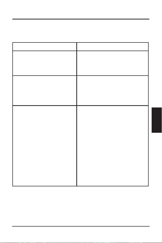

ProStar Operator’s Manual
73
5.0
Operation
72
Table 4-6. Maintenance Schedule (End)
Schedule Maintenance Items
Annually
Clean the heatsink fins with a
clean, dry rag.
Inspect all wiring for
damage or fraying.
Inspect for nesting insects.
Re-tighten all wiring
terminal connections to
specified torque values.
Inspect the system earth
grounding for all com-
ponents. Verify all grounding
conductors are appropriately
secured to earth ground.
5.1 Alarms
High Temperature Current Limit
The ProStar will limit the solar input current if the
heatsink temperature exceeds safe limits. Solar
charge current will be de-rated (to 0 Amps if needed)
to reduce the heatsink temperature. The ProStar
is designed to operate at full rated current at the
maximum rated ambient temperature. This alarm
indicates that there is insufficient airflow and that the
heatsink temperature is approaching unsafe limits. If
the controller frequently reports this alarm condition,
corrective action must be taken to provide better air
flow or to relocate the controller to a cooler spot.
RTS Open
The Remote Temperature Sensor is not connected to
the controller. Use of the RTS is recommended for
proper battery charging.
Heatsink Temperature Sensor Open or Shorted
The heatsink temperature sensor is damaged. Return
the controller to an authorized Morningstar dealer for
service.
Battery Sense Out of Range / Disconnected (only
alarm with LED indications)
Battery status LEDs: R/Y - G/Y sequencing. A battery
sense wire is disconnected. Inspect the battery sense
connections. This alarm is set when the voltage at the
5.0 TROUBLESHOOTING

Troubleshooting ProStar Operator’s Manual
75
74
5.0
battery sense terminals differs by more than five volts
from the voltage at the battery terminals.
Uncalibrated
The controller was not factory calibrated. Return the
controller to an authorized Morningstar dealer for
service.
5.2 LED Fault Indications
Solar Over-current
Error status LED: Flashing red. Battery status LEDs:
R/Y-G sequencing. When the ProStar’s rated input
current is exceeded, the unit will interrupt array
current until it falls below the controller's maximum
capacity.
If solar input exceeds 100% of the ProStar's current
rating, the average current will be reduced to the
ProStar’s maximum rating. The controller is capable of
managing up to 110% of the rated solar input. When
110% of rated current is exceeded, solar input will be
disconnected, and a fault will be indicated. The input
FET switches will remain open for ten (10) seconds.
Then the switches are closed again and charging can
resume. These cycles can continue without limit.
Load Over-current
Error Status LED: Flashing red. Battery status LEDs:
R/Y-G sequencing. If the load current exceeds
the maximum load current rating, the ProStar will
disconnect the load. The greater the overload, the
faster the load will be disconnected. A small overload
could take a few minutes to disconnect. The ProStar
will attempt to reconnect the load two (2) times. Each
attempt is approximately ten (10) seconds apart. If
the overload remains after two (2) attempts, the load
will remain disconnected until power is removed and
re-applied.
Solar Short Circuit
Charging Status LED: OFF. Solar input power wires
are short-circuited. Charging automatically resumes
when the short is cleared.
Battery Reverse Polarity
No LED indication, the unit is not powered. No
damage to the controller will result. Correct the
mis-wire to resume normal operation.
Load Short Circuit
Error status LED: Flashing red. Battery status LEDs:
R/G-Y sequencing. Fully protected against load wiring
short-circuits. After two (2) automatic load reconnect
attempts (10 seconds between each attempt) the
ProStar will wait, and then automatically reconnect the
load, once the short is cleared.
High Solar Voltage
Charging Status LED: R flashing. No battery status
indications. If the solar input open-circuit voltage (Voc)
exceeds the 60 Volt
maximum rating, the array will
remain disconnected until the Voc falls safely below the
maximum voltage.

Troubleshooting ProStar Operator’s Manual
77
76
5.0
Remote Temperature Sensor (RTS)
Error status LED: Flashing red. Battery status LEDs:
R/Y - G/Y sequencing. A bad RTS connection or a
severed RTS wire has disconnected the temperature
sensor during charging. Charging automatically resumes
when the problem is fixed. To resume operation without
an RTS, disconnect all power to the ProStar and then
reconnect. If the controller is re-started with the failure
still present, the controller may not detect that the RTS
is connected, and the LEDs will not indicate a fault. A
metered model, an RM-1 meter, or MSView PC software
can be used to determine if the RTS is working properly.
Solar-Battery High Voltage Disconnect (HVD)
Error status LED: Flashing red. Battery status LEDs:
R-G sequencing. This fault is set when battery voltage
is above normal operating limits. The controller
will disconnect the solar input and set a Solar High
Voltage Disconnect Fault. This fault is commonly
caused by other charging sources in the system,
charging the battery above the ProStar regulation
voltage. Recovery occurs at HVD re-connect threshold,
and the fault will clear automatically.
Load High Voltage disconnect (HVD) - disabled by
default
Error status LED: None. Battery status LEDs: R-G
sequencing. This fault is set when battery voltage
is above normal operating limits. The controller will
disconnect the load output and set a Load High
Voltage Disconnect fault. This fault is designed to
protect sensitive loads from excessive voltage.
Recovery occurs at HVD re-connect threshold, if
programmed, and the fault will clear automatically.
High Heatsink Temperature
Error status LED: Flashing red. Battery status LEDs:
R-Y sequencing. The heatsink temperature has
exceeded safe limits. Charging will cease, and the
load is disconnected. The load will automatically
be reconnected, and charging will resume when the
heatsink cools to a safe temperature.
Settings (DIP) Switch Changed
Error status LED: Flashing red. Battery status LEDs:
R-Y-G sequencing. If a settings switch is changed
while there is power to the controller, the LEDs
will begin sequencing and the solar input will be
disconnected. The controller must be re-started
to clear the fault and begin operation with the new
settings.
Custom Settings Edit
Error status LED: Flashing red. Battery status LEDs:
R-Y-G sequencing. A value has been modified in
custom settings memory. The controller will stop
charging and indicate a fault condition. After all
settings have been modified, the controller must be
reset by removing and then restoring power to the
controller. The new programmed settings will be used
after the power reset.

Troubleshooting ProStar Operator’s Manual
79
78
5.0
Firmware Update Failure
The firmware update was not successfully
programmed. The controller will not indicate the full
power-up LED sequence of G-Y-R when power to the
controller is reset. Instead, the controller will display
green, and then stop on yellow. The yellow LED will
continue to be lit and the controller will not complete
start up or begin charging. Re-try the firmware update.
The firmware must be successfully loaded before the
controller will start up.
Internal Power Supply Out-of-Range
Error status LED: Solid red. Battery status LEDs:
R-Y-G sequencing. The processor supply voltage is not
correct. Contact your Morningstar dealer for service.
SOLID CHARGING STATUS LED with SELF-TEST
(R-Y-G) SOC FAULTS
Verify that nothing has been mis-wired. If not, the error
is likely critical. Contact an authorized Morningstar
dealer for support.
Fault Charging Status LED
Battery
SOC LEDs
PV FET Short Solid red
R-Y-G
sequencing
Load FET Short Solid red
R-Y-G
sequencing
Load FET Open Solid red
R-Y-G
sequencing
Damaged local
temperature sensor
Solid red (only if RTS is
invalid)
R-Y-G
sequencing
Damaged heatsink
temperature sensor
Solid red
R-Y-G
sequencing
Software Solid red
R-Y-G
sequencing
Internal power supply
out of range
Solid red
R-Y-G
sequencing
RE-SETTABLE SELF-TEST (R-Y-G) SOC FAULTS
Fault - Battery SOC LEDs
Custom Settings Edit - R-Y-G sequencing
DIP Switch Change - R-Y-G sequencing
5.3 Battery Charging and Performance Issues
Problem:
No LED indications, controller does not appear to be
powered.
Solution:
With a multi-meter, check the voltage at the battery
terminals on the ProStar. Battery voltage must be 10
vdc or greater. If the voltage on the battery terminals
of the controller is between 10 and 35 vdc, and no
LEDs are lit, contact your authorized Morningstar
dealer for service. If no voltage is measured, check
wiring connections, fuses, and breakers.
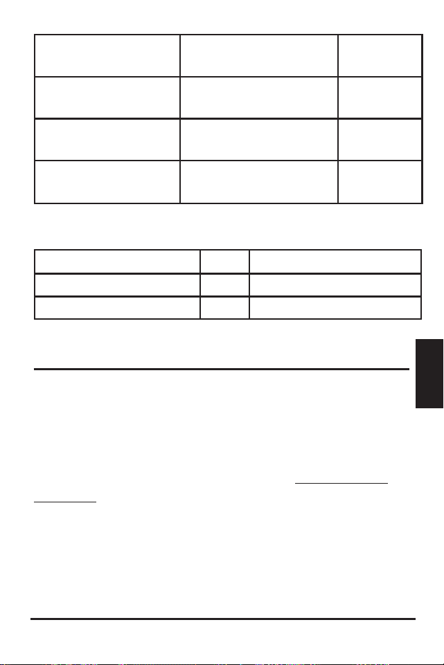

ProStar Operator’s Manual
81
6.0
Troubleshooting
80
Problem:
The ProStar is not charging the battery.
Solution:
Check the three (3) battery SOC LEDs. If they are
flashing in a sequence, see Section 5.2 - LED Fault
Indications - of this manual to determine the cause.
A metered model, an RM-1 meter, or MSView PC
software will display active faults and alarms.
If the LED indications are normal, check the fuses,
breakers, and wiring connections in the power source
wiring. With a multi-meter, check the array voltage
directly at the ProStar solar input terminals. Input
voltage must be greater than battery voltage before
charging will begin.
Problem:
Controller makes buzzing and humming noises.
Solution:
No action is required. This is expected due to
magnetic resonance and circuit switching.
If troubleshooting does not correct the problem,
please refer to Morningstar’s Warranty Claim
Procedure in Section 6.
WARRANTY
LIMITED WARRANTY - Morningstar Solar Controllers
and Inverters
Integrated Series products, SureSine Family (Gen 2)
inverters and other Morningstar Professional Series
TM
products, except the SureSine
TM
-300 Classic (Gen
1) inverter, are warrantied to be free from defects in
materials and workmanship for a period of FIVE (5)
years from the date of shipment to the original end
user. Warranty on replaced units, or field-replaced
components, will be limited only to the duration of the
original product coverage.
Morningstar Essentials Series
TM
products, and
SureSine
TM
-300 Classic (Gen 1) inverter, are warrantied
to be free from defects in materials and workmanship
for a period of TWO (2) years from the date of
shipment to the original end user. Warranty on
replaced units, or field-replaced components, will be
limited only to the duration of the original product
coverage.
Morningstar will, at its option, repair or replace any
such defective units.
CLAIM PROCEDURE:
Before requesting warranty service, check the
operator’s manual, including any troubleshooting
section, to verify product failure. To begin the warranty
replacement process, contact your authorized
6.0 WARRANTY AND POLICIES

Warranty and Policies ProStar Operator’s Manual
83
82
6.0
Morningstar distributor or dealer for assistance with
troubleshooting and, if necessary, obtaining an RMA
number.
An RMA number must be issued by Morningstar
prior to return of any unit(s) under this warranty.
Required RMA information:
(A) purchase location, date, business or company
name
(B) full model and serial numbers (SN is 8-digits on
unit bar label)
(C) failure behavior, including LED indications
(D) array configuration, panel Pmax, Voc, Vmp, Isc,
and nominal battery voltage - these specifications are
needed to receive assistance.
(E) multi-meter available (for field troubleshooting)
After the dealer is contacted, and is not able to assist
with warranty claim, contact Morningstar Technical
support at [email protected]. Please
provide proof of date and place of purchase, and all
details listed in preceding paragraph.
WARRANTY EXCLUSIONS AND LIMITATIONS:
This warranty does not apply under the following
conditions:
• damage by accident, negligence, abuse or improper
use
• PV or load currents exceeding the ratings of the
product
• unauthorized product modification or attempted
repair
• damage occurring during shipment
• damage resulting from acts of nature such as
lightning, weather extremes, or infestation
THE WARRANTY AND REMEDIES SET FORTH ABOVE
ARE EXCLUSIVE AND IN LIEU OF ALL OTHERS,
EXPRESS OR IMPLIED. MORNINGSTAR SPECIFICALLY
DISCLAIMS ANY AND ALL IMPLIED WARRANTIES,
INCLUDING, WITHOUT LIMITATION, WARRANTIES
OF MERCHANTABILITY AND FITNESS FOR A
PARTICULAR PURPOSE. No Morningstar distributor,
agent or employee is authorized to make any
modification or extension to this warranty.
MORNINGSTAR IS NOT RESPONSIBLE FOR
INCIDENTAL OR CONSEQUENTIAL DAMAGES OF
ANY KIND, INCLUDING BUT NOT LIMITED TO LOST
PROFITS, DOWN-TIME, GOODWILL OR DAMAGE
TO EQUIPMENT OR PROPERTY.
Morningstar Corporation
8 Pheasant Run, Newtown, PA 18940 USA
(215) 321-4457
www.morningstarcorp.com
support@morningstarcorp.com
R20-4/23

Warranty and Policies ProStar Operator’s Manual
83
82
6.0
Morningstar distributor or dealer for assistance with
troubleshooting and, if necessary, obtaining an RMA
number.
An RMA number must be issued by Morningstar
prior to return of any unit(s) under this warranty.
Required RMA information:
(A) purchase location, date, business or company
name
(B) full model and serial numbers (SN is 8-digits on
unit bar label)
(C) failure behavior, including LED indications
(D) array configuration, panel Pmax, Voc, Vmp, Isc,
and nominal battery voltage - these specifications are
needed to receive assistance.
(E) multi-meter available (for field troubleshooting)
After the dealer is contacted, and is not able to assist
with warranty claim, contact Morningstar Technical
support at support@morningstarcorp.com. Please
provide proof of date and place of purchase, and all
details listed in preceding paragraph.
WARRANTY EXCLUSIONS AND LIMITATIONS:
This warranty does not apply under the following
conditions:
• damage by accident, negligence, abuse or improper
use
• PV or load currents exceeding the ratings of the
product
• unauthorized product modification or attempted
repair
• damage occurring during shipment
• damage resulting from acts of nature such as
lightning, weather extremes, or infestation
THE WARRANTY AND REMEDIES SET FORTH ABOVE
ARE EXCLUSIVE AND IN LIEU OF ALL OTHERS,
EXPRESS OR IMPLIED. MORNINGSTAR SPECIFICALLY
DISCLAIMS ANY AND ALL IMPLIED WARRANTIES,
INCLUDING, WITHOUT LIMITATION, WARRANTIES
OF MERCHANTABILITY AND FITNESS FOR A
PARTICULAR PURPOSE. No Morningstar distributor,
agent or employee is authorized to make any
modification or extension to this warranty.
MORNINGSTAR IS NOT RESPONSIBLE FOR
INCIDENTAL OR CONSEQUENTIAL DAMAGES OF
ANY KIND, INCLUDING BUT NOT LIMITED TO LOST
PROFITS, DOWN-TIME, GOODWILL OR DAMAGE
TO EQUIPMENT OR PROPERTY.
Morningstar Corporation
8 Pheasant Run, Newtown, PA 18940 USA
(215) 321-4457
www.morningstarcorp.com
R20-4/23

Technical Specifications
ProStar Operator’s Manual
85
84
7.0
PS-15 PS-30
PS-15M PS-30M
Electrical:
Nominal Battery voltage 12 or 24 Volts
Battery voltage Range 10-35 Volts
Voltage accuracy 0.1% +/- 50mV (all)
Max. Battery Current 15 Amps 30 Amps
Max. PV open-circuit voltage 60 Volts
1
Load Current Rating 15 Amps 30 Amps
Self Consumption <22mA (no meter) <40mA (meter)
LED Indications (1) status, (3) battery SOC
Transient Surge Protection 1500 watts (solar, battery, load)
Mechanical:
Dimensions: 6.01(W) x 4.14(L) x 2.17(D) in.
153(W) x105(L) x 55(D) mm
Weight: 13.8 oz. (no meter)
15.1 oz. (with meter)
Wire Size Range:
Power Terminals 2.5 - 13.3 mm
2
/ #14 - 6
AWG
Maximum Torque 35 in-lb (4 N-m)
Battery/Temp. Sense 0.25 - 1.0 mm
2
/ #24 - 16 AWG
Enclosure IP20, Type 1
Battery Charging:
4-Stage Charging: Bulk, Absorption, Float, Equalize
Temperature compensation
Coefficient: -30mV / ºC / 12 Volt
Temperature compensated
set-points: Absorption, Float, Equalize, HVD
7.0 TECHNICAL SPECIFICATIONS
1
Hardware specification - not for design purposes
Battery Charging Set-points (@ 25°C):
[multiply voltages by (2) for 24 Volt systems]
DIP
Switch
S
ettings
4
-5-6
B
attery
T
ype
A
bsorp.
S
tage
(
volts)
F
loat
S
tage
(
volts)
E
qualize
S
tage
(
volts)
A
bsorp.
T
ime
(
mins)
E
qualize
T
ime
(
mins)
E
qualize
T
imeout
(
mins)
E
qualize
I
nterval
(
days)
off-off-off
1 - Sealed*
14.00
13.50
150
off-off-on
2 - Sealed*
14.15
13.50
14.40
150
60
120
28
off-on-off
3 - Sealed*
14.30
13.50
14.60
150
60
120
28
off-on-on
4- AGM/Flooded
14.40
13.50
15.10
180
120
180
28
on-off-off
5 - Flooded
14.60
13.50
15.30
180
120
180
28
on-off-on
6 - Flooded
14.70
13.50
15.40
180
180
240
28
on-on-off
7 - L-16
15.40
13.40
16.00
180
180
240
14
on-on-on
8 - Custom
Custom
Custom
Custom
Custom
Custom
Custom
Custom
* “Sealed” ba�ery type includes gel and AGM ba�eries
Current Compensation:
12 Volt systems -15 mV/A
24 Volt systems -30 mV/A
Compensated set-points LVD, LVR
Load and Solar Control:
[multiply voltages by (2) for 24 Volt systems]
Default values (customizable)
LVD
1
11.5V
LVR
1
12.6V
Instant LVD 10.0V
HVD - solar Highest set-point in
preset charging profile
[+ 0.5V (@ 25ºC)]
HVD - load
1
Disabled
HVDR - solar 13.8V (@ 25ºC)
HVDR - load
1
Disabled
LVD Warning 10 mins

Technical Specifications
ProStar Operator’s Manual
87
86
7.0
1
Applies to units with Firmware v18 and
higher
LVD Override - Lighting Test 10 mins
Maximum # LVD overrides No limit unless
(not customizable) V_batt < Instant LVD
Lighting Control (DIP 1 ON):
Lighting Timer Setting Dusk-Dawn (default)
Lighting Test Timer 10 mins
Data & Communications:
Communication Port MeterBus (RJ-11)
Comm. Protocols Morningstar MeterBus;
MODBUS
Data-logging 6-8 months, daily records
PC Software MSView
Digital Meter:
Resolution 128 x 64 pixels
Viewing Area 50 mm x 25 mm
Display Color blue on white
Backlight LED
Operating Temperature -20ºC to +70ºC
Storage Temperature -30ºC to +80ºC
Environmental:
Maximum Operating Altitude 2000 meters
Ambient Temperature Range:
T5 Certified -40°C to +60°C
Storage Temperature -40ºC to +80ºC
Humidity 100% n.c.
Tropicalization Conformally coated PCBs;
Marine-rated terminals
For hazardous location-IECEx/ATEX applications,
see the
addendum - part no. MS-003245-EN - to this manual.
Protections
Power-up against any active faults
Reverse Polarity - battery and array
Solar Short-circuit
Solar Over-current
High Solar Voltage Disconnect
High Heatsink Temperature - Current de-rating
High Heatsink Temperature - Load disconnect
Load Short-circuit
Load Over-current
Heatsink Temperature Limit
RTS Terminals
Battery Sense Terminals
PWM Current De-rating
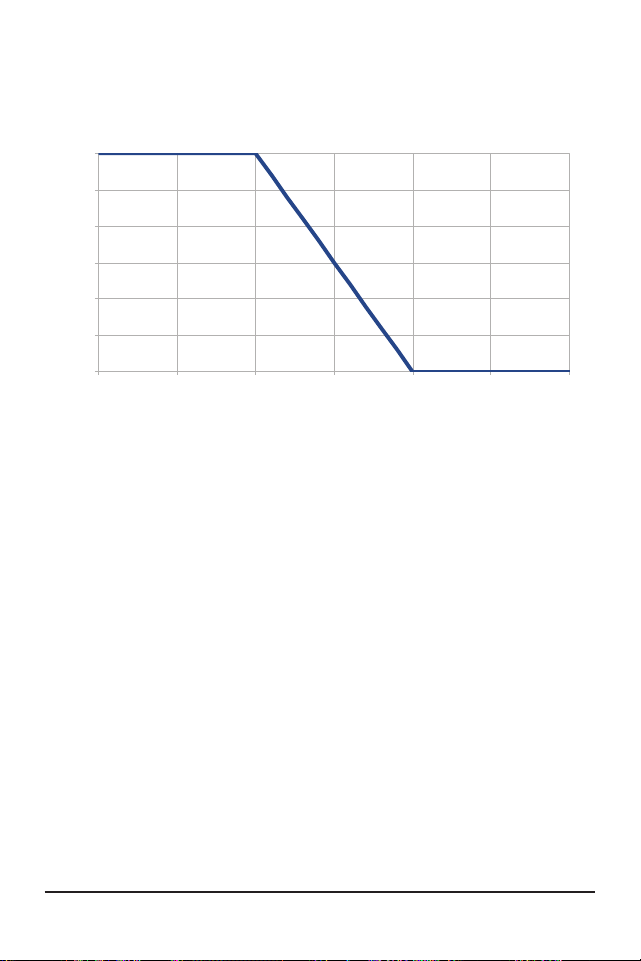
Technical Specifications88
ProStar Operator’s Manual
89
Appendices
Wire Size
(AWG)
30A 25A 20A 15A 10A 8A 5A
2*
24.6 29.5 36.9 49 61 92.0
3*
19.5 23.3 29.2 38.9 49 73.0
4*
15.5 18.6 23.2 31.0 38.7 58 93.0
6
9.7 11.6 14.6 19.4 24.3 36.4 58.0
8
6.1 7.4 9.2 12.3 15.3 23.0 36.8
10
3.8 4.6 5.8 7.7 9.6 14.4 23.1
12
2.9 3.6 4.8 6.0 9.0 14.4
14
2.3 3.0 3.8 5.7 9.1
* Wire sizes larger than #6 AWG must be terminated at a splicer
block located external to the ProStar. Use #6 AWG or smaller wire
to connect the ProStar to the splicer block.
Table B-1. Maximum one-way circuit length for 12 Volt systems,
stranded copper (Feet) , 2% voltage drop
2% Voltage Drop Chart for 75°C or 90ºC Stranded
Copper Wire (Feet), 12 Volt System /
Maximum 1-way Distance (feet), 12 Volt System -
multiply values by (2) for 24 Volt and by (4) for 48V,
system. NOTE: Distances are estimates only and
can vary based on temperature, type of wire or other
factors.
0
5
10
15
20
25
30
35 40 45 50 55 60 65
Maximum Current (A)
Ambient Temperature (◦C)
Thermal Derate
Figure A-1. Maximum Current vs. Ambient Temperature
APPENDIX A - DERATING
APPENDIX B - Voltage Drop Tables for Wire
Sizing
Good system design generally requires large
conductor wires that limit voltage drop losses to 2%
or less. The tables below provide wire sizing for a
maximum of 2% voltage drop. Longer distance wire
runs may require significantly larger wire sizes to
reduce the voltage drop to an acceptable level.
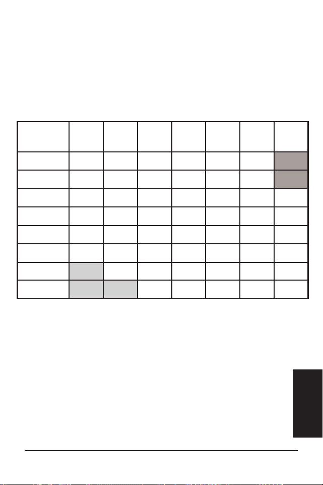

Technical Specifications90
ProStar Operator’s Manual
91
Appendices
Wire Size
(mm
2
)
30A 25A 20A 15A 10A 8A 5A
35*
7.5 9.0 11.3 15.0 22.6 28.2 45.1
25*
5.4 6.5 8.1 10.8 16.3 20.3 32.5
16
3.4 4.1 5.2 6.9 10.3 12.9 20.6
10
2.2 2.6 3.2 4.3 6.5 8.1 12.9
6
1.3 1.5 1.9 2.6 3.8 4.8 7.7
4
0.9 1.0 1.3 1.7 2.6 3.2 5.1
2.5
0.8 1.1 1.6 2.0 3.2
* Wire sizes larger than13.3 mm
2
must be terminated at a splicer
block located external to the ProStar. Use 13.3 mm
2
or smaller wire
to connect the ProStar to the splicer block.
Table B-2. Maximum one-way circuit length for 12 Volt systems,
stranded copper (Meters) , 2% voltage drop.
2% Voltage Drop Chart for 75°C or 90ºC Stranded
Copper Wire (meters), 12 Volt System /
Maximum 1-way Distance (meters), 12 Volt system -
multiply values by (2) for 24 Volt system and by (4) for
48V system. NOTE: Distances are estimates only and
can vary based on temperature, type of wire or other
factors.
FOR CURRENT DETAILED CERTIFICATION LISTINGS,
REFER TO:
https://www.morningstarcorp.com/support/library
Choose the ProStar-PWM product, and under, “Type”,
choose, “Declaration of Conformity" (DOC).
ProStar
TM
and MeterBus
TM
are trademarks of
Morningstar Corporation
MODBUS
TM
and MODBUS TCP/IP
TM
are trademarks of
Modbus IDA.
©2024 Morningstar Corporation. All rights reserved.
MS-001533 v4.2

PROSTAR GEN 3 ADDENDUM TO
OPERATOR’S MANUAL
Certifications
UL1741 INVERTERS, CONVERTERS, AND
CONTROLLERS AND INTERCONNECTION SYSTEM
EQUIPMENT FOR USE WITH DISTRIBUTED ENERGY
SOURCES, SECOND EDITION, REVISION THROUGH
AND INCLUDING SEP 07, 2016
CSA C22.2#107.1-01 POWER CONVERSION
EQUIPMENT
UL121201/CSA C22.2 #213 Non-incendive Electrical
Equipment for Use in Class I, Division 2 Hazardous
(Classified) Locations, Groups A,B,C,D, Temperature
Group: T5 (see product manual environmental
specifications)
EMC Directives
• Immunity: EN 61000-6-2
• Emissions: EN 61000-6-4
CISPR 55022
REACH
ALL
COMPONENTS
COMPLIANT
Registration, Evaluation and
Authorization of Chemicals
1
Low Voltage Directive:
IEC/EN 62109-1
Hazardous Locations for IECEx/ATEX Applications
IECEx ETL 20.0068X
ITS20ATEX25936X
IECEx: Ex ec ic IIC T5 Gc
ATEX: II 3G Ex ec ic IIC T5 Gc
-40°C ≤ Tamb ≤ +60°C
Prostar Gen 3 must be verified with di-electric
strength test specified by the relevant industrial
standard.
The equipment must be placed inside an Ex-rated
IP 54 enclosure in accordance with IEC 60079 series.
A tool is required in order to access the equipment
inside the enclosure.
2
10611 Iron Bridge Road, Ste. L, Jessup, MD 20794 USA
8 Pheasant Run, Newtown, PA 18940 USA
Morningstar Corporation
MS-003245-EN-5