Loading ...
Loading ...
Loading ...
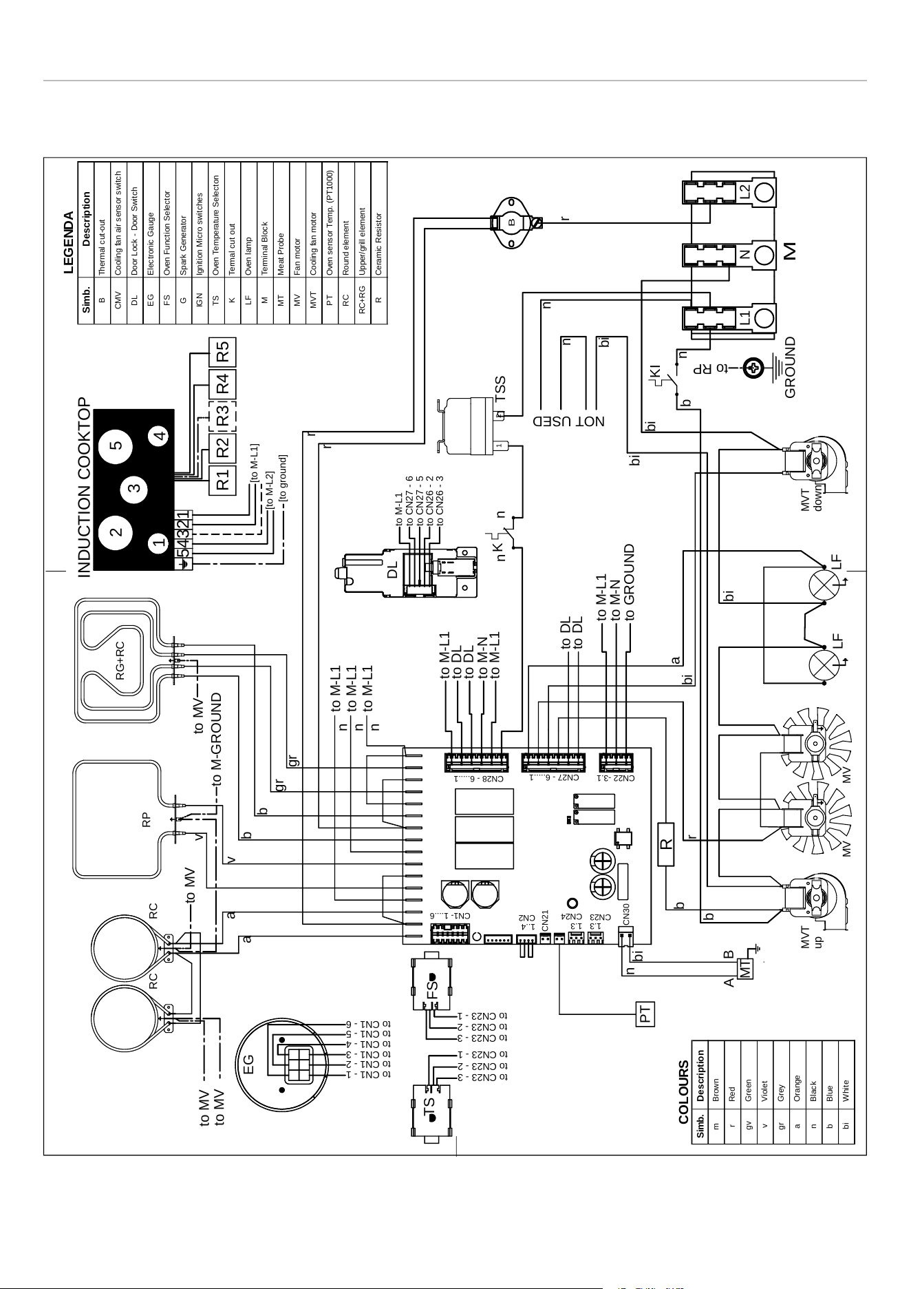
WIRING DIAGRAM
The electric wiring diagrams and schematics are attached behind the range, and should not be removed except by a
service technician, then replaced after service.
Fig. 11
to CN1 - 1
to CN1 - 2
to CN1 - 3
to CN1 - 4
to CN1 - 5
to CN1 - 6
EG
M
L1NL2
GROUND
LF
LF
MVMV
MVT
down
MVT
up
PT
RG+RC
RP
RC
RC
Simb.Description
mBrown
rRed
gvGreen
vViolet
grGrey
aOrange
nBlack
bBlue
biWhite
COLOURS
Simb.Description
BThermal cut-out
CMVCooling fan air sensor switch
DLDoor Lock - Door Switch
EGElectronic Gauge
FSOven Function Selector
GSpark Generator
IGNIgnition Micro switches
TSOven Temperature Selecton
KTermal cut out
LFOven lamp
MTerminal Block
MTMeat Probe
MVFan motor
MVTCooling fan motor
PTOven sensor Temp. (PT1000)
RCRound element
RC+RGUpper/grill element
RCeramic Resistor
LEGENDA
CN1- 1....6
1..4
CN2
CN21
1.3
CN24
1.3
CN23
CN30
CN22 -3.1
CN27 - 6.....1
CN28 - 6.....1
DL
to M-L1
to CN27 - 6
to CN27 - 5
to CN26 - 2
to CN26 - 3
to M-L1
to DL
to DL
to M-N
to M-L1
TS
to CN23 - 3
to CN23 - 2
to CN23 - 1
FS
to CN23 - 3
to CN23 - 2
to CN23 - 1
to DL
to DL
to M-L1
to M-N
to GROUND
TSS
1
2
K
B
n
to M-L1
to M-L1
to M-L1
R1
R2
R3
R4
R5
1
2
3
4
5
12345
INDUCTION COOKTOP
[to M-L2]
[to M-L1]
[to ground]
MT
A
B
a
a
v
v
b
b
gr
gr
r
r
n
n
n
n
n
bi
bi
bi
bi
b
r
a
bi
r
n
n
n
bi
to MV
to MV
to MV
to MV
to M-GROUND
to RP
NOT USED
R
b
b
KI
n
18
Loading ...
Loading ...
Loading ...