2 Operating instructions ecoTEC sustain 0020253095_03
Operating instructions
Contents
1 Safety ............................................ 3
1.1 Action-related warnings ................. 3
1.2 Intended use .................................. 3
1.3 General safety information............. 4
2 Notes on the documentation ...... 7
2.1 Observing other applicable
documents ..................................... 7
2.2 Storing documents......................... 7
2.3 Validity of the instructions .............. 7
3 Product description..................... 7
3.1 Product design............................... 7
3.2 Control elements............................ 7
3.3 Description of the display............... 8
3.4 Information on the identification
plate ............................................... 8
3.5 Serial number ................................ 9
3.6 CE marking .................................... 9
3.7 Benchmark..................................... 9
3.8 Energy Saving Trust Endorsed
Products....................................... 10
3.9 Production date............................ 10
4 Operation.................................... 10
4.1 Operating concept ....................... 10
4.2 Opening the isolator devices ....... 11
4.3 Switching on the product ............. 11
4.4 Setting the heating flow
temperature ................................. 11
4.5 Setting the hot water
temperature ................................. 12
4.6 Switching off the product's
functions ...................................... 12
4.7 Guaranteeing the correct filling
pressure in the heating circuit...... 13
4.8 Switching the product to
standby mode .............................. 14
4.9 Protecting the heating
installation against frost ............... 14
5 Troubleshooting ........................ 14
5.1 Detecting and rectifying faults...... 14
5.2 Displaying the status codes ......... 14
6 Care and maintenance .............. 14
6.1 Maintenance ................................ 14
6.2 Caring for the product .................. 15
6.3 Reading maintenance
messages .................................... 15
6.4 Checking the condensate
discharge pipe and tundish.......... 15
7 Decommissioning...................... 15
7.1 Temporarily decommissioning
the product................................... 15
7.2 Permanently decommissioning
the product................................... 15
8 Recycling and disposal............. 15
9 Guarantee and customer
service ........................................ 16
9.1 Guarantee.................................... 16
9.2 Customer service......................... 16
Appendix ............................................... 17
A Operator level – overview ......... 17
B Status codes – Overview........... 17
C Troubleshooting and fault
elimination.................................. 18
C.1 Troubleshooting ........................... 18
C.2 Rectifying faults ........................... 18
0020253095_03 ecoTEC sustain Operating instructions 3
1 Safety
1.1 Action-related warnings
Classification of action-re-
lated warnings
The action-related warnings
are classified in accordance
with the severity of the pos-
sible danger using the follow-
ing warning signs and signal
words:
Warning symbols and signal
words
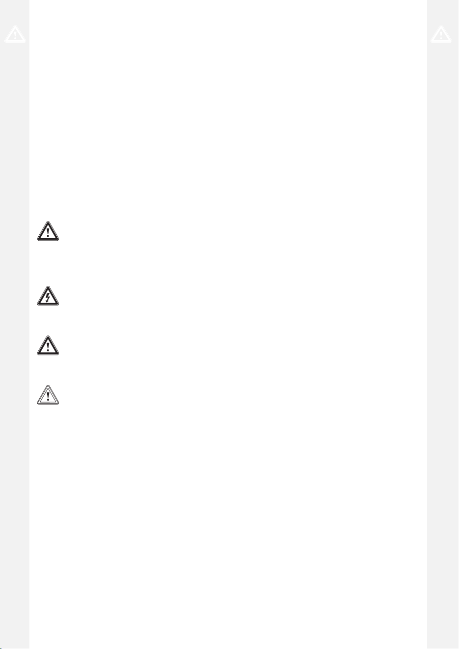
Danger!
Imminent danger to life
or risk of severe personal
injury
Danger!
Risk of death from electric
shock
Warning.
Risk of minor personal
injury
Caution.
Risk of material or envir-
onmental damage
1.2 Intended use
There is a risk of injury or death
to the user or others, or of dam-
age to the product and other
property in the event of im-
proper use or use for which it
is not intended.
The product is intended as a
heat generator for sealed heat-
ing installations and for do-
mestic hot water generation.
Intended use includes the fol-
lowing:
– observance of the operating
instructions included for the
product and any other install-
ation components
– compliance with all inspection
and maintenance conditions
listed in the instructions.
This product can be used by
children aged from 8 years
and above and persons with
reduced physical, sensory or
mental capabilities or lack of
experience and knowledge if
they have been given supervi-
sion or instruction concerning
use of the product in a safe way
and understand the hazards in-
volved. Children must not play
with the product. Cleaning and
user maintenance work must
not be carried out by children
unless they are supervised.
Any other use that is not spe-
cified in these instructions, or
use beyond that specified in this
document, shall be considered
improper use. Any direct com-
mercial or industrial use is also
deemed to be improper.
Caution.
Improper use of any kind is
prohibited.

4 Operating instructions ecoTEC sustain 0020253095_03
1.3 General safety
information
1.3.1 Danger caused by
improper operation
Improper operation may present
a danger to you and others, and
cause material damage.
▶ Carefully read the enclosed
instructions and all other ap-
plicable documents, particu-
larly the "Safety" section and
the warnings.
▶ Only carry out the activities
for which instructions are
provided in these operating
instructions.
1.3.2 Risk of death from
escaping gas
What to do if you smell gas in
the building:
▶ Avoid rooms that smell of
gas.
▶ If possible, open doors and
windows fully and ensure
adequate ventilation.
▶ Do not use naked flames (e.g.
lighters, matches).
▶ Do not smoke.
▶ Do not use any electrical
switches, mains plugs, door-
bells, telephones or other
communication systems in
the building.
▶ If it is safe to do so, close the
emergency control valve or
the main isolator.
▶ If possible, close the gas
stopcock on the product.
▶ Warn other occupants in the
building by yelling or banging
on doors or walls.
▶ Leave the building immedi-
ately and ensure that others
do not enter the building.
▶ Notify the gas supply
company or the Emer-
gency Service Provider
+44 (0) 800 111999 by tele-
phone once you are outside
of the building.
1.3.3 Risk of death due to
blocked or leaking flue
pipework
What to do if you smell flue gas
in the property:
▶ Open all accessible doors
and windows fully to provide
ventilation.
▶ Switch off the product.
▶ Inform a competent person.
1.3.4 Risk of death due to
explosive and flammable
materials
▶ Do not use the product in
storage rooms that contain
explosive or flammable sub-
stances (such as petrol, pa-
per or paint).

0020253095_03 ecoTEC sustain Operating instructions 5
1.3.5 Risk of death due to
changes
to the product or the
product environment
▶ Never remove, bridge or
block the safety devices.
▶ Do not tamper with any of the
safety devices.
▶ Do not damage or remove
any tamper-proof seals on
components.
▶ Do not make any changes:
– The product itself
– to the gas, supply air, water
and electricity supply lines
– to the entire flue system
– to the entire condensate
discharge system
– to the expansion relief valve
– to the drain pipework
– to constructional condi-
tions that may affect the
operational reliability of the
product
1.3.6 Risk of poisoning
caused by insufficient
combustion air supply
Condition: Open-flued opera-
tion
▶ Ensure that there is a suffi-
cient combustion air supply.
1.3.7 Risk of
corrosion damage due to
unsuitable combustion
and room air
Sprays, solvents, chlorinated
cleaning agents, paint, adhes-
ives, ammonia compounds,
dust or similar substances may
lead to corrosion on the product
and in the air/flue pipe.
▶ Ensure that the combustion
air supply is always free of
fluorine, chlorine, sulphur,
dust, etc.
▶ Ensure that no chemical sub-
stances are stored at the in-
stallation site.
1.3.8 Risk of material damage
caused by frost
▶ Ensure that the heating in-
stallation always remains in
operation during freezing con-
ditions and that all rooms are
sufficiently heated.
▶ If you cannot ensure the oper-
ation, have a competent per-
son drain the heating installa-
tion.
1.3.9 Risk of injury and
material damage due to
maintenance and repairs
carried out incorrectly or
not carried out at all
▶ Never attempt to carry out
maintenance work or repairs
on your product yourself.

6 Operating instructions ecoTEC sustain 0020253095_03
▶ Faults and damage should
be immediately rectified by a
competent person.
▶ Adhere to the maintenance
intervals specified.
0020253095_03 ecoTEC sustain Operating instructions 7
2 Notes on the
documentation
2.1 Observing other applicable
documents
▶ You must observe all operating instruc-
tions enclosed with the system compon-
ents.
2.2 Storing documents
▶ Keep this manual and all other applic-
able documents safe for future use.
2.3 Validity of the instructions
These instructions apply only to:
Product article number
ecoTEC
sustain 24
VUW 246/7-2
(H-GB)
0010019980
ecoTEC
sustain 28
VUW 286/7-2
(H-GB)
0010019981
ecoTEC
sustain 34
VUW 346/7-2
(H-GB)
0010019982
Gas Council Numbers
ecoTEC
sustain 24
VUW 246/7-2
(H-GB)
47-044-79
ecoTEC
sustain 28
VUW 286/7-2
(H-GB)
47-044-80
ecoTEC
sustain 34
VUW 346/7-2
(H-GB)
47-044-81
3 Product description
This product is a gas-fired wall-hung con-
densing boiler.
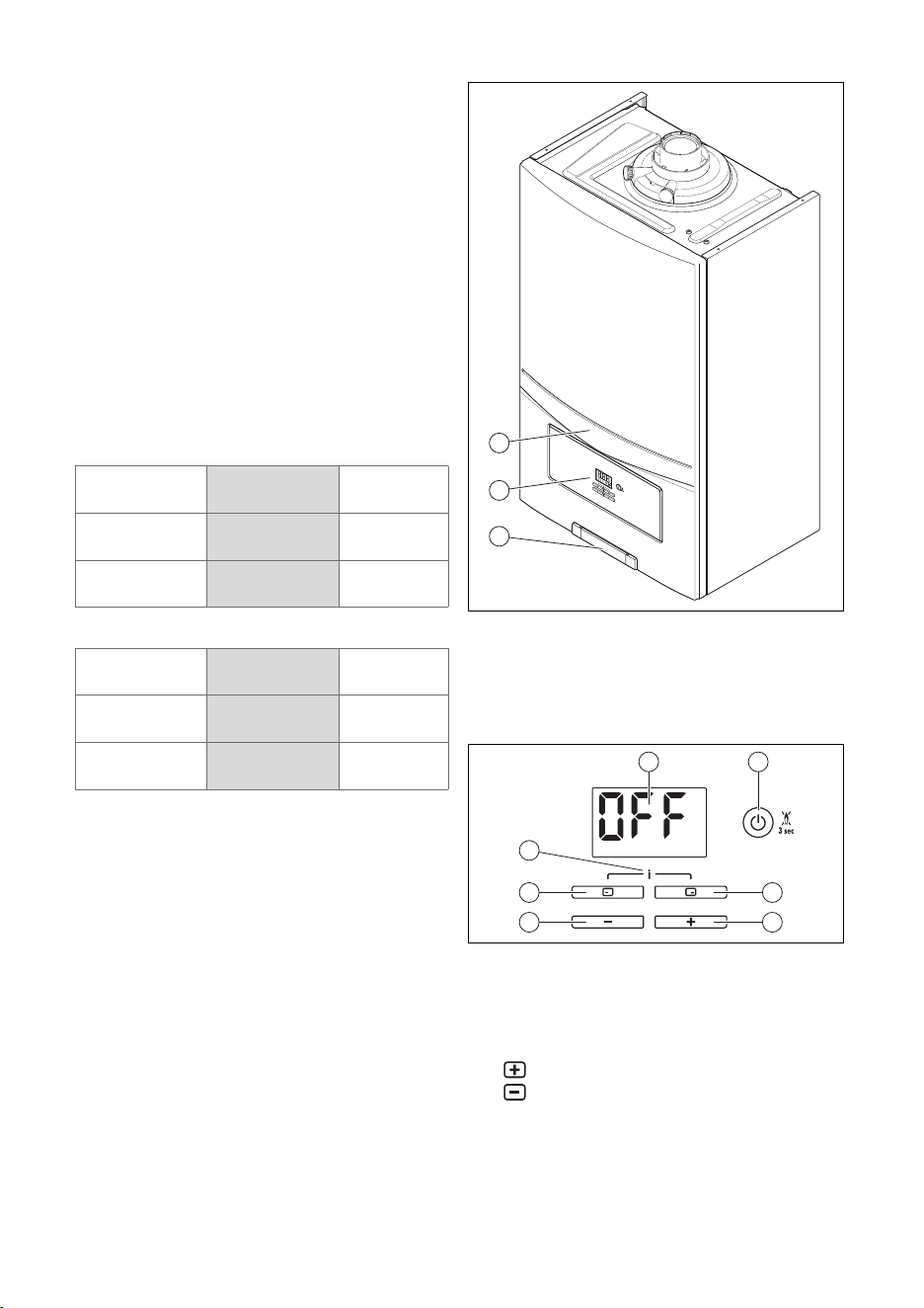
3.1 Product design
3
2
1
1 Product
2 Control elements
3 Plate with serial
number on the
rear
3.2 Control elements
3
4
6
5
7
1 2
1 Display
2 On/off button
and reset button
3 Right selection
button
4 button
5 button
6 Left selection
button
7 Access to the
menu for addi-
tional inform-
ation/installer
level
8 Operating instructions ecoTEC sustain 0020253095_03
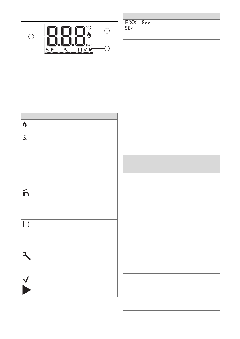
3.3 Description of the display
1
2
3
1 Operating in-
formation
2 Operating mode,
selecting and
confirming the
operating mode
3 Display showing
the current heat-
ing flow temper-
ature, the filling
pressure in the
heating install-
ation, the oper-
ating mode or a
fault code
Symbol Meaning
Burner operating correctly
– Burner on
Heating installation filling
pressure
– Permanently on: Filling
pressure in the permitted
range
– Flashing: Filling pres-
sure outside the permit-
ted range, purging func-
tion activated
DHW mode
– Permanently on: Hot wa-
ter activated
– Flashing: Burner on in
draw-off mode
Heating mode
– Permanently on: Heating
mode activated
– Flashing: Burner on in
heating mode
Maintenance required
Information on maintenance
messages in the event of
faults
Setting to be confirmed
Navigating through various
menus
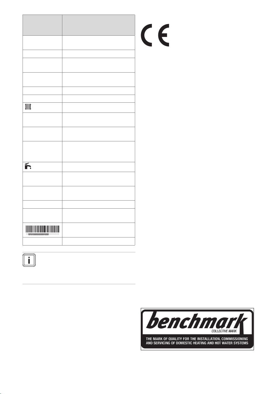
Symbol Meaning
/ /
Fault in the product
– Appears instead of the
basic display.
S.XX
Status code
OFF – Heating mode is switched
off (summer mode)
– Hot water handling mode
is switched off (product
with integrated hot water
generation)
– Appears when the
product goes into standby
mode.
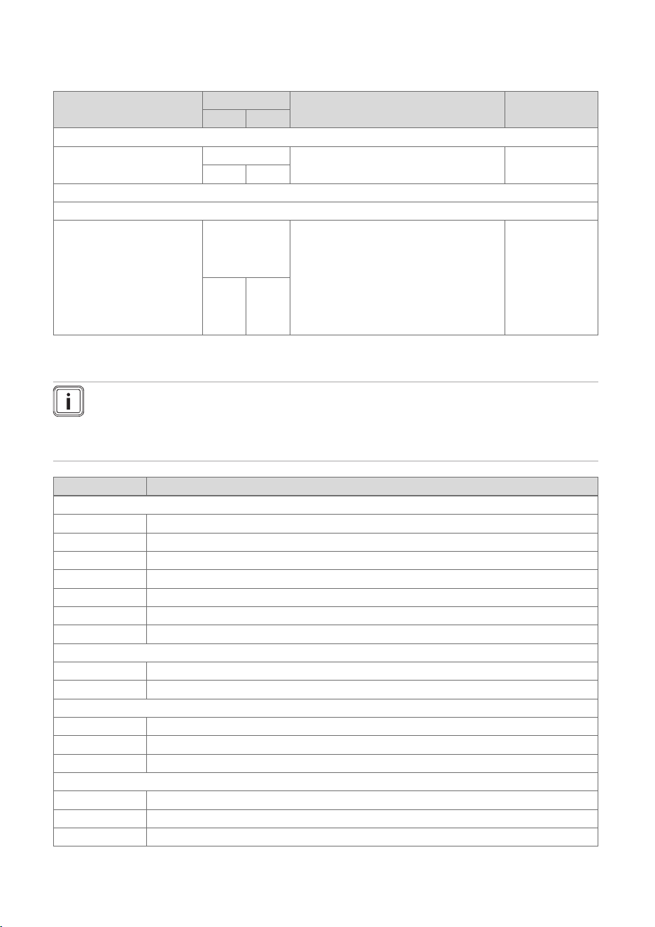
3.4 Information on the
identification plate
The identification plate is mounted on the
underside of the product in the factory.
The identification plate keeps record of
the country in which the product is to be
installed.
Information
on the identi-
fication plate
Meaning
Condensing
technology
Efficiency class of the boiler
in accordance with EC Dir-
ective 92/42/EEC
Serial number For quality control purposes;
3rd and 4th digits = year of
production
For quality control purposes;
5th and 6th digits = week of
production
For identification purposes;
7th to 16th digits = product
article number
For quality control purposes;
17th to 20th digits = place of
manufacture
... ecoTEC ... Product designation
Cat. Approved gas category
Type: Xx3(x) Permissible flue gas connec-
tions
2H / 2E / 3P /
2K...
Gas group and gas connec-
tion pressure as set at the
factory
Tmax Max. flow temperature
0020253095_03 ecoTEC sustain Operating instructions 9
Information
on the identi-
fication plate
Meaning
PMS Maximum water pressure in
heating mode
NOx NOx class for the product
V
Hz
Electric connection
W Max. electrical power con-
sumption
IP Protection class
Code (DSN) Specific product code
Heating mode
Qn Nominal heating load range
in heating mode
Pn Nominal heat output range
in heating mode
Pnc Nominal heat output range
in heating mode (condensing
technology)
Hot water generation
Qnw Nominal heating load range
in hot water handling mode
Pnw Nominal heat output range
in hot water handling mode
D Specific flow rate
PMW Maximum water pressure in
hot water handling mode
Barcode with serial number
GC No. Gas council number
Note
Make absolutely sure that the
product is compatible with the gas
group at the installation site.
3.5 Serial number
The serial number can be found on the
rear of a plastic plate at the bottom of the
front casing and on the identification plate.
3.6 CE marking
The CE marking shows that the products
comply with the basic requirements of the
applicable directives as stated on the de-
claration of conformity.
The declaration of conformity can be
viewed at the manufacturer's site.
3.7 Benchmark
Vaillant is a licensed member of the
Benchmark Scheme.
Benchmark places responsibilities on both
manufacturers and installers. The purpose
is to ensure that customers are provided
with the correct equipment for their needs,
that it is installed, commissioned and ser-
viced in accordance with the manufac-
turer’s instructions by a competent per-
son approved at the time by the Health
and Safety Executive and that it meets the
requirements of the appropriate Building
Regulations. The Benchmark Checklist
can be used to demonstrate compliance
with Building Regulations and should be
provided to the customer for future refer-
ence.
Installers are required to carry out installa-
tion, commissioning and servicing work in
accordance with the Benchmark Code of
Practice which is available from the Heat-
ing and Hotwater Industry Council who
manage and promote the Scheme.
Benchmark is managed and promoted by
the Heating and Hotwater Industry Coun-
cil.
For more information visit
www.centralheating.co.uk
10 Operating instructions ecoTEC sustain 0020253095_03
3.8 Energy Saving Trust Endorsed
Products
Only the most energy efficient products
can carry the ‘Energy Saving Trust En-
dorsed Product’ brandmark making it easy
for consumers to choose products that
have met strict energy performance cri-
teria.
Available for: Boilers, Heating controls and
chemical inhibitors, the Energy Saving
Trust endorsed product brandmark gives
consumers confidence that a product will
cost less to run, help lower energy bills
and reduce carbon emissions.
About the Energy Saving Trust
Energy Saving Trust is an independent
and impartial organisation that provides
trusted energy saving advice to empower
millions of people to lead affordable, low
energy lifestyles. For more information visit
energysavingtrust.org.uk
3.9 Production date
You can find the production date (week,
year) in the serial number on the data
plate:
– The third and fourth digit in the serial
number specify the year of production
(two digits).
– The fifth and sixth digit of the serial
number specify the week of production
(from 01 to 52).
4 Operation
4.1 Operating concept
The display switches on when you switch
on the product or press a button. You can
now configure settings by pressing the
buttons again.
When you switch the product off using the
on/off button, the display goes out (the
frost protection function is active for as
long as power is supplied).
Button Meaning
– Setting the hot water temperat-
ure
– Cancelling the change to a set
value or activating an operating
mode
– Calling up a higher selection
level in the menu
– Setting the heating flow tem-
perature, filling pressure of the
heating system or activating the
heating mode
– Confirming a set value or activ-
ating an operating mode
– Calling up a lower selection
level in the menu
– Read the system pressure
(press twice)
+
– Calling up the additional func-
tions
or
– Navigating between individual
menu items
– Increasing or decreasing the
chosen set value
–
On/off button (press and hold
the button for < 3 s)
– Reset button (press and hold
the button for > 3 s)
Both selection buttons have a soft key
function, i.e. their function can change.
If, for example, you press the left-hand
selection button in the basic display,
the current function switches from
(Domestic hot water temperature) to
(Back).
Adjustable values are always displayed as
flashing.
0020253095_03 ecoTEC sustain Operating instructions 11
You must always confirm a change to a
value. Only then is the new setting saved.
You can press to cancel a procedure at
any time. If you do not press any buttons
for longer 15 minutes, the display returns
to the basic display.
4.1.1 Basic display
The basic display shows the current
product status.
To return to the basic display, press the
button. If you do not press any buttons
within three minutes, the display becomes
dark and automatically switches back to
the basic display.
If an error message appears, the error
code will be shown on the basic display.
The available functions vary depending on
whether:
– A room thermostat is connected to the
product or not
– A domestic hot water cylinder with tem-
perature sensor is connected to the
product or not
4.1.2 Operating levels
The product has two operating levels:
– The operator level shows the most im-
portant information and offers set-up op-
tions which do not require any special
prior knowledge.
– Specialised knowledge is required in or-
der to use the installer level (access for
competent persons). This is therefore
protected by an access code.
4.2 Opening the isolator devices
1. Ask the competent person who in-
stalled the product to explain to you
where these isolator devices are loc-
ated and how to handle them.
2. Open the gas isolator cock installed
on-site.
3. Open the gas isolator cock, which
is directly below the product or in its
immediate vicinity.
4. Open the service valves in the heating
installation's flow and return.
5. Open the cold water stop valve.
4.3 Switching on the product
1. Only start up the product once the
casing has been completely closed.
2. If the display is switched off, press
for less than 3 seconds.
◁ The basic display is shown in the
display.
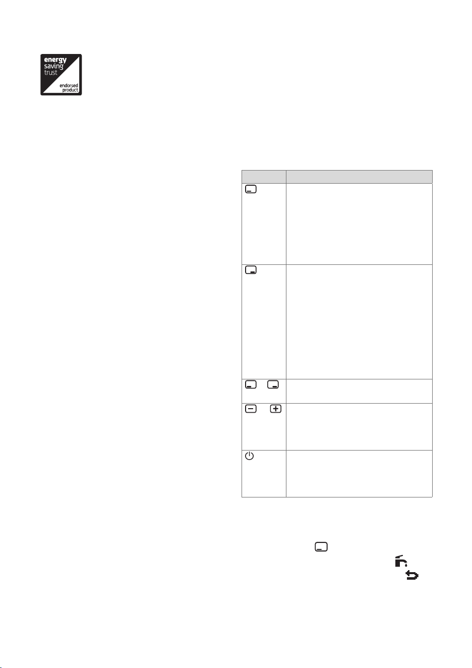
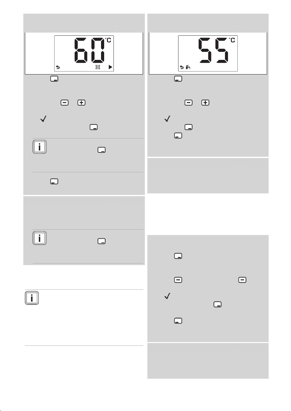
4.4 Setting the heating flow
temperature
Note
If the eBUS room temperature con-
trol is connected to the product,
the domestic hot water temperat-
ure and the heating flow temperat-
ure cannot be set via the operating
display.
12 Operating instructions ecoTEC sustain 0020253095_03
Condition: The temperature is controlled by the
product
▶ Press .
◁ The heating flow temperature flashes
in the display.
▶ Press the or button to set the
temperature.
◁ is shown in the display.
▶ Confirm by pressing .
Note
If you press the button again,
the heating installation pressure
is shown in the display.
▶ Press .
◁ The basic display is shown.
Condition: Controller-regulated temperature
▶
You cannot set the heating flow temper-
ature.
Note
If you press the button, the
heating installation pressure is
shown in the display.
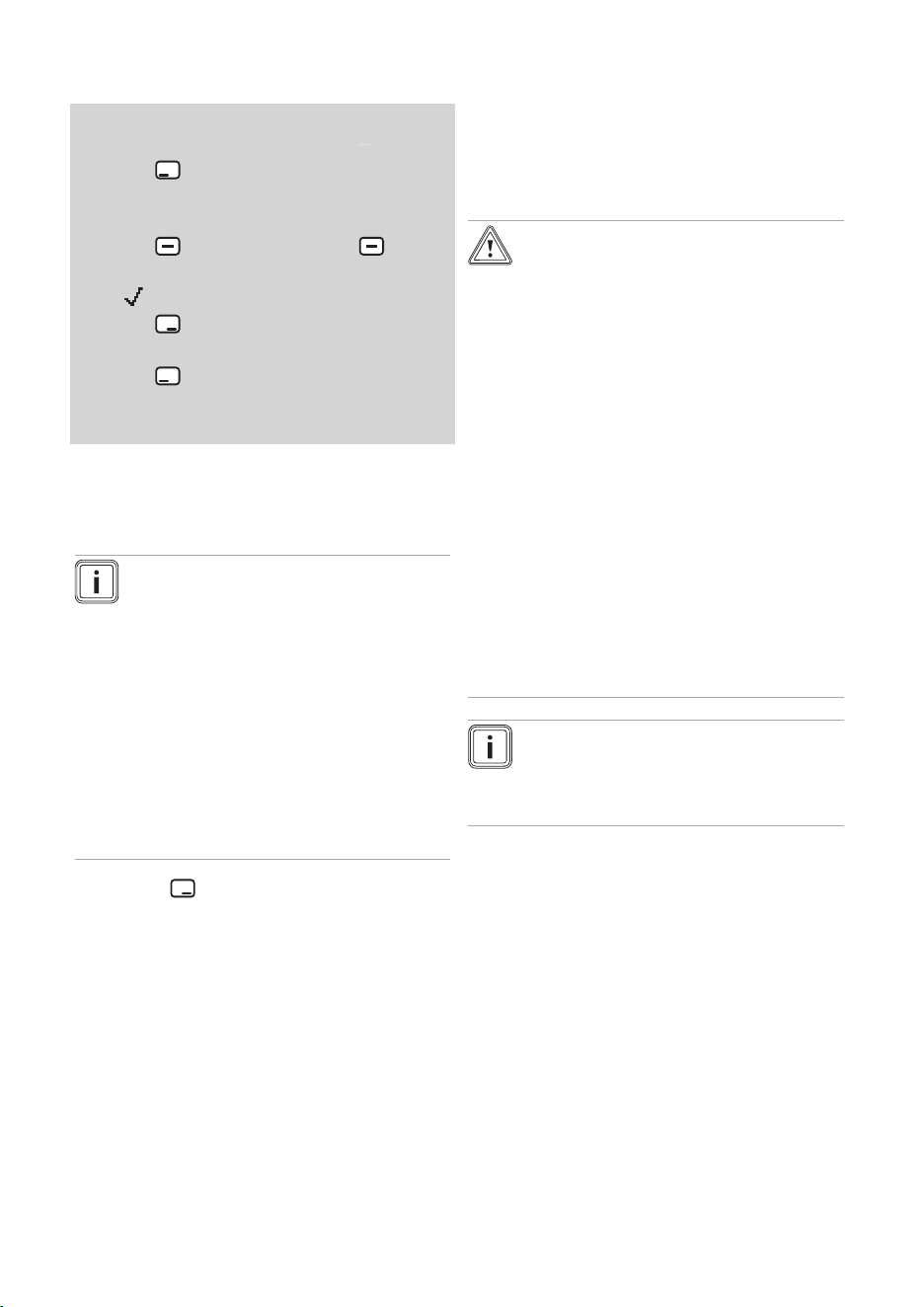
4.5 Setting the hot water
temperature
Note
If the eBUS room temperature con-
trol is connected to the product,
the domestic hot water temperat-
ure and the heating flow temperat-
ure cannot be set via the operating
display.
Condition: The temperature is controlled by the
product
▶ Press .
◁ The domestic hot water temperature
now flashes in the display.
▶ Press the or button to set the
temperature.
◁ is shown in the display.
▶ Press the button to confirm.
▶ Press .
◁ The display switches to the basic
display.
Condition: Controller-regulated temperature
▶ Set the hot water temperature on the
controller. See the instructions for the
controller.
4.6 Switching off the product's
functions
4.6.1 Switching off heating mode
(Summer mode)
Condition: The temperature is controlled by the
product
▶ Press .
◁ The heating flow temperature flashes
in the display.
▶ Press and press and hold until
OFF is shown in the display.
◁ is shown in the display.
▶ Confirm by pressing .
◁ Heating mode is switched off.
▶ Press .
◁ The display switches to the basic
display.
Condition: Controller-regulated temperature
▶ You cannot switch off heating mode on
the product. See the instructions for the
controller.
0020253095_03 ecoTEC sustain Operating instructions 13
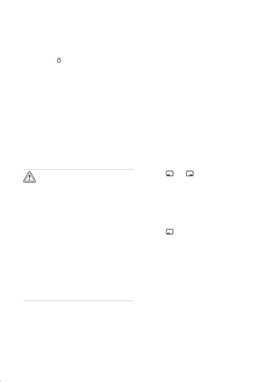
4.6.2 Switching off the hot water
handling mode
Condition: Temperature regulated by the product or
by the room temperature controller
▶ Press .
◁ The domestic hot water temperature
now flashes in the display.
▶ Press and press and hold until
OFF is shown in the display.
◁ is shown in the display.
▶ Press to confirm.
◁ Hot water generation is switched off.
▶ Press .
◁ The display switches to the basic
display.
4.7 Guaranteeing the correct filling
pressure in the heating circuit
4.7.1 Checking the system pressure
Note
Your product has a pressure
sensor and a digital pressure
display.
The product switches to fault mode
if the pressure falls below the re-
quired system pressure (below
0.05 MPa (0.5 bar)). If the heat-
ing installation extends over sev-
eral floors, a higher system pres-
sure may be necessary. Ask your
competent person for details.
1. Press twice.
◁ The current system pressure is
shown in the display.
2. Check the system pressure on the
display.
Result 1:
System pressure: 0.08 to 0.2 MPa
(0.80 to 2.0 bar)
The system pressure is in the inten-
ded pressure range.
Result 2:
System pressure: < 0.08 MPa
(< 0.80 bar)
▶ Fill the heating installation.
(→ Page 13)
◁ Once you have reached a suffi-
cient pressure range, the display
will disappear after 20 seconds.
4.7.2 Filling the heating installation
Caution.
Risk of material damage due
to heating water that is ex-
tremely calciferous or corros-
ive or contaminated by chem-
icals.
Unsuitable tap water damages
the seals and diaphragms,
blocks components in the
product and heating installation
through which the water flows
and causes noise.
▶ Only fill the heating installa-
tion with suitable heating wa-
ter.
▶ In case of doubt, ask a com-
petent person for details.
Note
The competent person is respons-
ible for filling the heating installa-
tion the first time.
1. On-site, connect the filling cock to a
cold water pipe, as explained by the
competent person.
2. Open all radiator valves (thermostatic
radiator valves) of the heating installa-
tion.
3. Open the cold water pipe.
4. Turn the filling cock on slowly and
allow water to flow in until the required
system pressure has been reached.
5. Close the cold water pipe.
6. Purge all radiators.
7. Check the system pressure on the
display. (→ Page 13)
8. Top up with more water if required.
14 Operating instructions ecoTEC sustain 0020253095_03
9. Close the filling cock.
10. Disconnect the filling cock from the
cold water pipe.
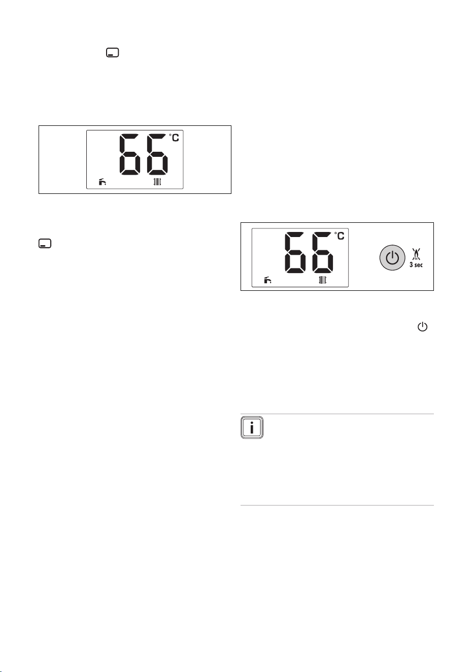
4.8 Switching the product to
standby mode
▶ Press the button for less than three
seconds.
◁ Once the requirement currently in
use has finished, the display will
show OFF and go out.
◁ The product is now in standby mode.
◁ The product's frost protection func-
tion is activated.
◁ The main power supply is not inter-
rupted. The product continues to be
supplied with power.
4.9 Protecting the heating
installation against frost
4.9.1 Frost protection function
Caution.
Risk of material damage due
to frost.
The frost protection function
cannot guarantee flow through
the entire heating installation,
which means that parts of the
heating installation may freeze
and therefore become dam-
aged.
▶ During a period of frost, en-
sure that the heating installa-
tion remains in operation and
that all rooms are sufficiently
heated, even when you are
away.
To keep the frost protection devices active,
you should switch your product on and off
using the controller, if one is provided.
If the heating flow temperature falls be-
low 5 °C when the on/off button is on, the
product comes into operation and heats
the circulating water to approx. 30 °C on
both the heating side and the hot water
side (if available).
4.9.2 Draining the heating
installation
When the unit is switched off for an exten-
ded period, frost protection can be guaran-
teed by completely draining the heating in-
stallation and the product.
▶ Consult a competent person about this.
5 Troubleshooting
5.1 Detecting and rectifying faults
▶ If faults occur or fault messages (F.XX)
are displayed, proceed as set out in the
tables in the appendix.
▶ If the product is not functioning cor-
rectly, contact a competent person.
5.2 Displaying the status codes
1. Press and at the same time.
◁ S.XX is shown in the display, fol-
lowed by the heating flow temper-
ature and the internal system pres-
sure.
2. Look up the meaning of the status
codes.
Status codes – Overview (→ Page 17)
3. Press .
◁ The display switches to the basic
display.
6 Care and maintenance
6.1 Maintenance
An annual inspection of the product carried
out by a competent person is a prerequis-
ite for ensuring that the product is perman-
ently ready and safe for operation, reliable,
and has a long working life.
0020253095_03 ecoTEC sustain Operating instructions 15
6.2 Caring for the product
▶ Clean the casing with a damp cloth and
a little solvent-free soap.
▶ Do not use sprays, scouring agents,
detergents, solvents or cleaning agents
that contain chlorine.
6.3 Reading maintenance
messages
If the symbol is shown in the display,
the product requires maintenance work.
The product is not in fault mode but contin-
ues to operate.
▶ Consult a competent person about this.
▶ If the water pressure is flashing at the
same time, simply add more heating
water.
6.4 Checking the condensate
discharge pipe and tundish
The condensate discharge pipe and tun-
dish must always be penetrable.
▶ Regularly check the condensate dis-
charge pipe and tundish for faults and,
particularly, for blockages.
You must not be able to see or feel any
obstructions in the condensate discharge
pipe and tundish.
▶ If you notice a fault, have it eliminated
by a competent person.
7 Decommissioning
7.1 Temporarily decommissioning
the product
Caution.
Risk of material damage due
to frost.
The frost protection and mon-
itoring devices are only active
while the product is connected
to the power grid and switched
on via the on/off button, and
when the gas stopcock is open.
▶ Temporarily decommission
the product only if no frost is
expected.
▶ Press the on/off button.
◁ The display goes out.
▶ When decommissioning the product
for a prolonged period (e.g. holiday),
close the gas isolator cock and also, for
combination products, the cold water
stop valve.
7.2 Permanently decommissioning
the product
▶ Have a competent person permanently
decommission the product.
8 Recycling and disposal
▶ The competent person who installed
your product is responsible for the dis-
posal of the packaging.
If the product is labelled with this
mark:
▶ In this case, do not dispose of the
product with the household waste.
▶ Instead, hand in the product to a collec-
tion centre for waste electrical or elec-
tronic equipment.
If the product contains batteries that
are labelled with this mark, these batteries
may contain substances that are hazard-
ous to human health and the environment.
▶ In this case, dispose of the batteries at
a collection point for batteries.

16 Operating instructions ecoTEC sustain 0020253095_03
9 Guarantee and customer
service
9.1 Guarantee
– One year guarantee for ecoTEC sustain
appliances
Vaillant provides this appliance with a
parts and labour guarantee against de-
fects that may occur within twelve months
of the installation date.
– Registering with us
Registration is simple. Just complete the
Guarantee Registration Card and return to
Vaillant within 30 days of installation. Your
details will then be automatically registered
within the Vaillant scheme.
– Immediate help
If your Vaillant boiler develops a fault your
first action should be to contact your in-
staller, as his professional assessment is
needed under the terms of our Guarantee.
If you are unable to contact your installer,
phone Vaillant Service Solutions:
Telephone: 0330 100 3461
9.2 Customer service
To ensure regular servicing, it is strongly
recommended that arrangements are
made for a Maintenance Agreement.
Please contact Vaillant Service Solutions
for further details:
Telephone: 0330 100 3461
0020253095_03 ecoTEC sustain Operating instructions 17
Appendix
A Operator level – overview
Setting level Values Increment, select, explanation Default set-
ting
Min. Max.
DHW mode
Hot water temperature Current value < 35 = OFF OFF
35 ℃ 60 ℃
Heating mode
Heating flow temperat-
ure
Current value < 10 = OFF
Underfloor heating = 35-50
Radiator = 35-80
Note
The temperature range above 75 °C
can only be set by a competent per-
son.
OFF
10 ℃ 80 ℃
B Status codes – Overview
Note
Since the code table is used for various products, some codes may not be vis-
ible for the product in question.
Codes that are not listed here can be found in the installation instructions.
Status code Meaning
Displays in heating mode
S.00 Heating mode: No requirement
S.02 Heating mode: Pump pre-run
S.03 Heating mode: Burner ignition
S.04 Heating mode: Burner on
S.06 Heating mode: Fan overrun
S.07 Heating mode: Pump overrun
S.08 Heating mode: Temporary shutdown after heating procedure
Displays in hot water handling mode
S.10 Hot water handling mode: Requirement
S.14 DHW mode: Burner on
Display in Comfort mode with warm start or hot water handling mode with cylinder
S.20 Hot water handling mode: Requirement
S.22 Hot water handling mode: Pump pre-run
S.24 DHW mode: Burner on
Other displays
S.31 No heating demand: Summer mode, eBUS controller, waiting period
S.34 Frost protection active
S.46 Protection mode: Minimum load
18 Operating instructions ecoTEC sustain 0020253095_03
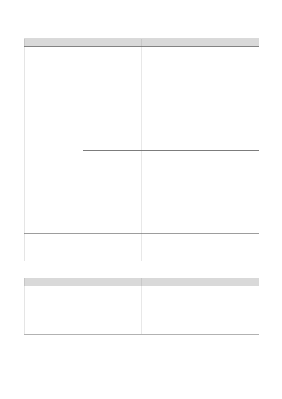
C Troubleshooting and fault elimination
C.1 Troubleshooting
Symptom Possible cause Measure
The system pres-
sure is flashing on the
display
The system pressure
is too low: < 0.05 MPa
(< 0.50 bar). Low wa-
ter pressure in the
heating installation.
▶ Fill the heating installation. (→ Page 13)
The system pressure
is too high: > 0.3 MPa
(> 3 bar).
▶ Wait until the excess heating water has
flowed out through the expansion relief
valve.
Product does not start
up (no hot water,
heating remains cold)
The gas isolator cock
installed on-site and/or
the gas isolator cock
on the product is
closed.
▶ Open both gas isolator cocks.
The cold water stop
valve is closed.
▶ Open the cold water stop valve.
The product is
switched off.
▶ Switch on the product. (→ Page 11)
The heating flow tem-
perature/domestic
hot water temperat-
ure has been set too
low and/or the heat-
ing mode/domestic hot
water generation has
been switched off.
1. Set the heating flow temperature.
(→ Page 11)
2. Set the hot water temperature.
(→ Page 12)
There is air in the
heating installation.
▶ Have a competent person purge the heating
installation.
Hot water generation
functioning correctly;
heating does not start
up
The external controller
is not set correctly.
▶ Set the external controller correctly (→Con-
troller operating instructions).
C.2 Rectifying faults
Code/meaning Possible cause Measure
F.28
Ignition unsuccessful
After three unsuc-
cessful ignition at-
tempts, the product
has switched to fault
mode.
1. Check whether the gas isolator cock is
open.
2. Press the reset button for longer than
three seconds.
3. If you have been unable to eliminate the
ignition fault after the fault clearance at-
tempt, consult a competent person.


Supplier
Vaillant Ltd.
Nottingham Road Belper Derbyshire DE56 1JT
Telephone 0330 100 3461
[email protected] www.vaillant.co.uk
Publisher/manufacturer
Vaillant GmbH
Berghauser Str. 40 D-42859 Remscheid
Tel. +492191 18 0 Fax +492191 18 2810
[email protected] www.vaillant.de
© These instructions, or parts thereof, are protected by copyright and may be
reproduced or distributed only with the manufacturer's written consent.
Subject to technical modifications.
0020253095_03