1
OHR-100 RECHARGEABLE
LI-ION BATTERY SYSTEM
INSTRUCTION MANUAL
WEEE Number: 80133970
In case of any query/issue with the product, please reach out to us at: support@v-tac.eu
For More products range, inquiry please contact our distributor or nearest dealers.
V-TAC EUROPE LTD. Bulgaria, Plovdiv 4000, bul.L.Karavelow 9B
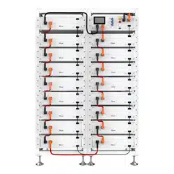
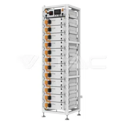
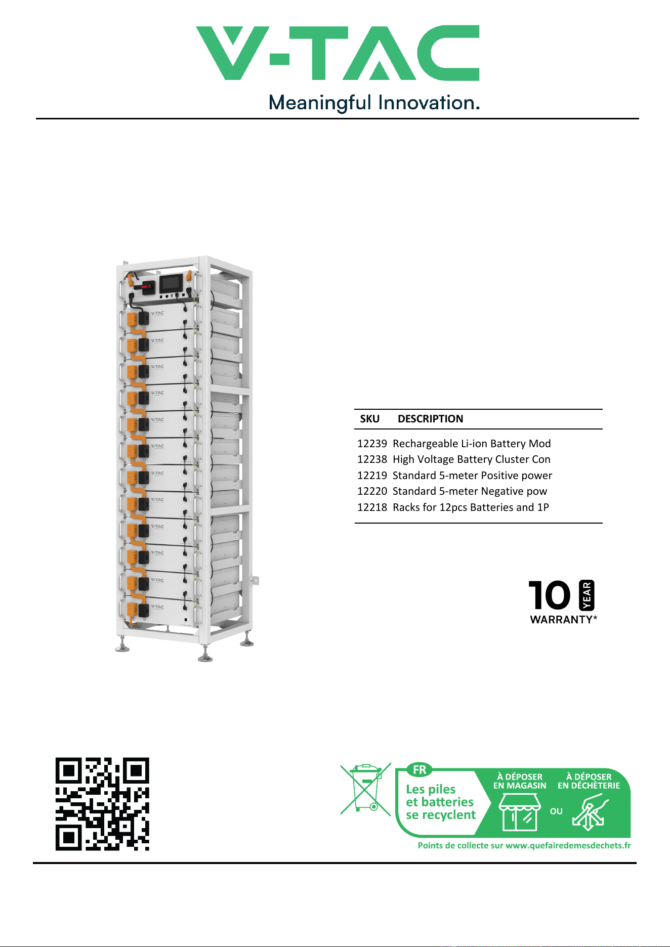
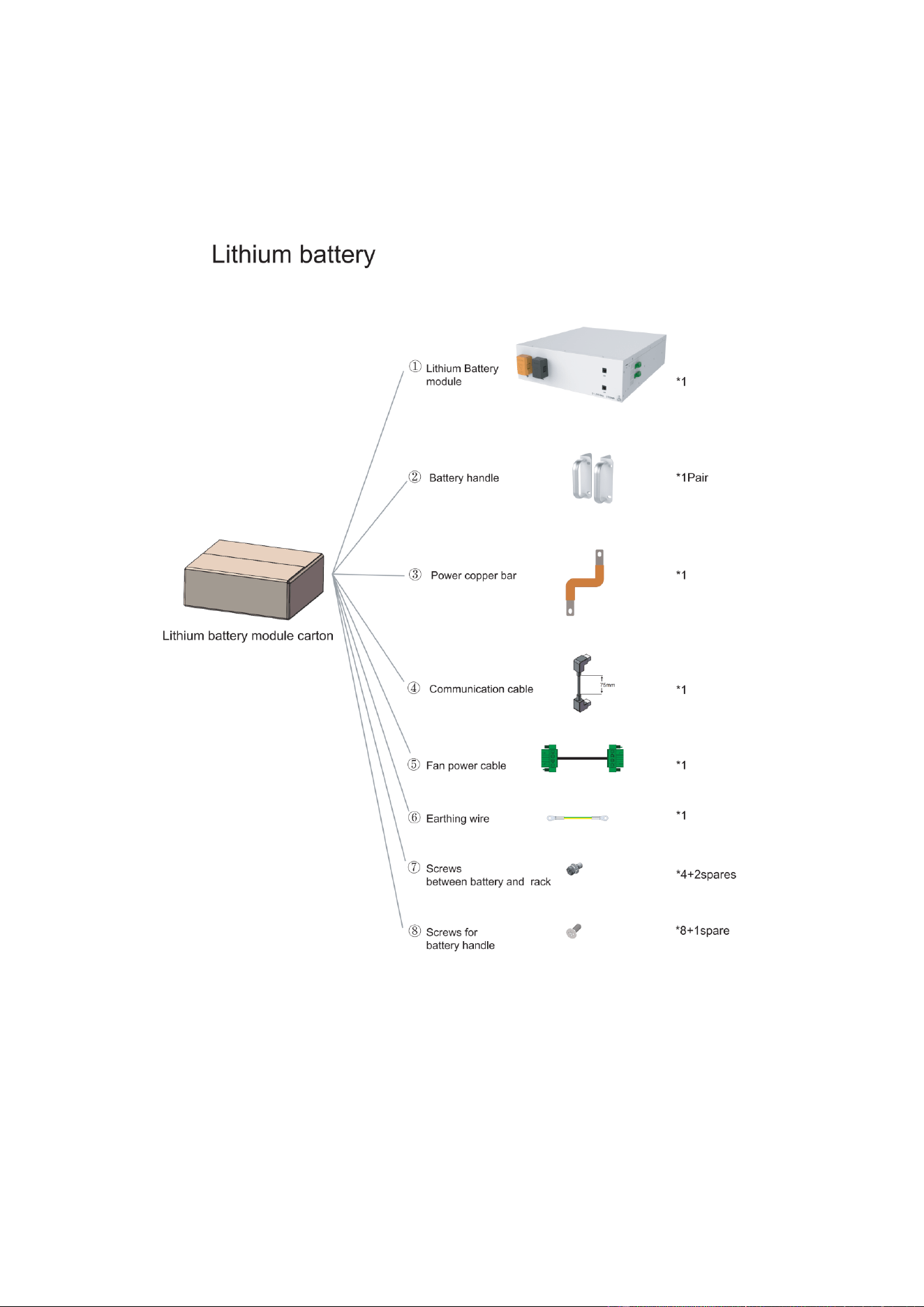
12239 Rechargeable Li-ion Battery Module
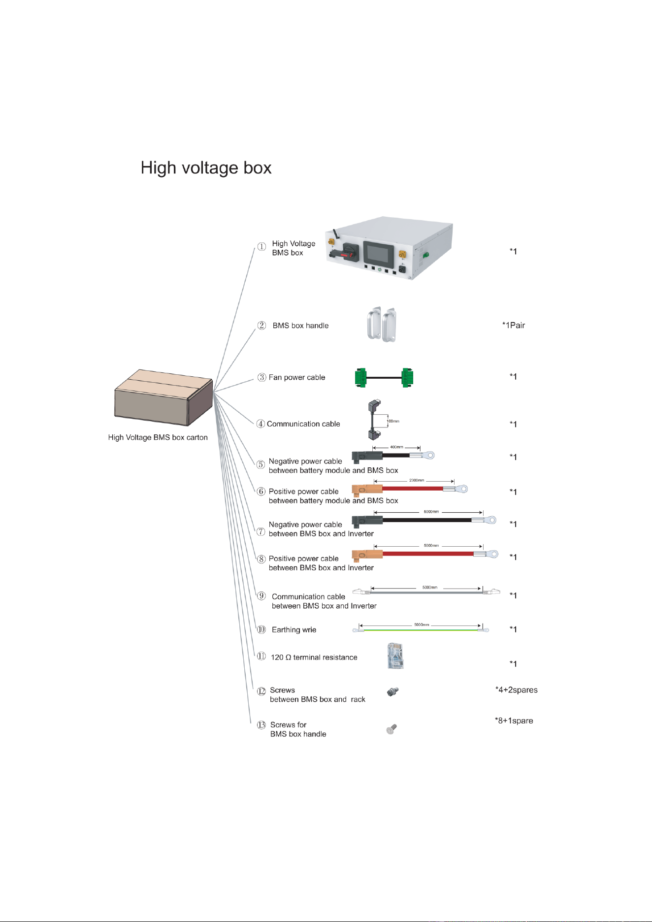
12238 High Voltage Battery Cluster Control Box
12219 Standard 5-meter Positive power cable
12220 Standard 5-meter Negative power cable
12218 Racks for 12pcs Batteries and 1PC BMS
SKU DESCRIPTION
INTRODUCTION
Thank you for selecting and buying V-TAC Product. V-TAC will serve you the best. Please
read these instructions carefully & keep this user manual handy for future reference. If you
have any another query, please contact our dealer or local vendor from whom you have
purchased the product. They are trained and ready to serve you at the best.
MULTI-LANGUAGE
MANUAL QR CODE
Please scan the QR code
to access the manual in
multiple languages.

CONTENT
1.Important information in the manual...............................................................................3
1.1 Scope ......................................................................................................................3
1.2 Description of OHR-100 ..........................................................................................3
1.3 Meaning of Symbols ...............................................................................................4
1.4 General Safety Information .....................................................................................6
1.5 Disclaimer ................................................................................................................6
1.6 Installation environment............................................................................................6
1.7 Requirements for Installation Personnel .................................................................8
2. Safety...............................................................................................................................9
2.1 Safety rules .............................................................................................................9
2.2 Safety information ...................................................................................................9
3. Transport to the end customers.....................................................................................9
3.1 Provisions on Shipping of Battery Modules:...........................................................9
3.2 Permissible and Impermissible Storage Positions of a Packaged Battery Module10
4. Description and installation of OHR-100 battery ........................................................ 11
4.1 Installation Precautions......................................................................................... 11
4.2 OHR-100 Product Description ............................................................................... 11
4.3 Technical Data....................................................................................................... 11
4.4. Preparation ..........................................................................................................
13
4.4.1 Tools required .............................................................................................13
4.4.2 OHR-3U-HRACK Parts description ............................................................13
4.4.3 Installation of Rack......................................................................................14
4.5 Description of Battery Module...............................................................................17
4.6 Description of high-voltage BMS box....................................................................18
4.7 Description of Battery Module in Rack..................................................................19
4.8 Installation of the Battery Module to the Rack ......................................................21
4.9 Battery cluster connected to inverter ....................................................................24
4.10 System startup and shutdown ............................................................................27
1
Startup procedure................................................................................................27
④ Complete boot.
..............................................................................................27
④Complete shutdown.
......................................................................................27
5 OHR’S User Interface .............................................................................................28
5.1 Main Interface.......................................................................................................28
5.2 Cell Voltage ..........................................................................................................28
5.3 Cell Temperature ..................................................................................................29
5.4 Heating Temperature............................................................................................29
5.5 Relay Status .........................................................................................................30
5.6 Other.....................................................................................................................30
5.6.1 Heating Information....................................................................................31
5.6.2 Insulation Resistense
.................................................................................31

5.6.3 Diagnostic Information ............................................................................. 32
5.6.4 Cumulative Time Information ................................................................... 32
5.7 Set Up ................................................................................................................ 33
6 Xiaodan Energy Storage App ............................................................................... 34
6.1. App download ................................................................................................... 34
6.1.1 Android version .......................................................................................... 34
6.1.2 iOS version ........................................................................................................ 34
6.2. Log in and register ............................................................................................... 35
6.2.1 Log in .......................................................................................................... 35
6.2.2 Register ...................................................................................................... 36
6.2.3 Experience login ......................................................................................... 37
6.3. Equipment distribution network ........................................................................... 38
6.3.1 Overview .................................................................................................... 38
6.3.2 Distribution process .................................................................................... 38
6.4. App page ............................................................................................................. 43
6.4.1 Equipment .................................................................................................. 43
6.4.2 Data details ................................................................................................ 46
6.4.3 Mine ............................................................................................................ 46
6.4.4 Message ..................................................................................................... 51
6.4.5 App settings ................................................................................................ 52
7 Maintenance ................................................................................................................... 54
2
1.Important information in the manual
1.1 Scope
The installation and operation manual applies to the modular battery energy storage system.
Please carefully read this installation and operation manual to ensure the safe installation,
preliminary debugging, and maintenance of OHR-100. Installation, preliminary debugging, and
maintenance must be carried out by qualified and authorized personnel. Please keep this
installation and operation manual and other applicable documents near the battery energy
storage system, so that all personnel involved in installation or maintenance can access this
installation and operation manual at any time.
This installation and operation manual only applies to countries meeting the certification
requirements. Please observe the applicable local laws, regulations, and standards. Standards
and legal provisions of other countries may be inconsistent with the provisions and
specifications in this manual. In this case, please contact our after-sales service personnel.
1.2 Description of OHR-100
3
1.3 Meaning of Symbols
This manual contains the following types of warnings:
Danger! It may cause an electric shock.
Even when the equipment is disconnected from the power grid, the voltage-free
state will have a time lag.
Danger! If the instructions are not observed, death or severe injury may
occur.
Warning! If the instructions are not observed, a loss may occur.
Attention! This symbol represents information on the device use.
Symbols on equipment:
The following types of warning, prohibition, and mandatory symbols are also used on
the equipment.
Attention!
The risk of chemical burns
If the battery is damaged or fails, it may lead to electrolyte leakage, which in turn
causes the formation of a small amount of hydrofluoric acid, among other effects.
Contact with these liquids can cause chemical burns.
• Do not subject the battery module to severe impact.
• Do not open, disassemble or mechanically change the battery module.
• In case of contact with an electrolyte, wash the affected area with clean water
immediately and seek medical advice promptly.
4
Attention! The risk of explosion
Incorrect operation or fire may cause the lithium-ion battery unit to ignite or explode,
leading to serious injury.
• Do not install or operate the battery module in explosive or high-humidity areas.
• Store the battery module in a dry place within the temperature range specified in
the data sheet.
• Do not open, drill through or drop the battery cell or module.
• Do not expose the battery cell or module to high temperatures.
• Do not throw the battery cell or module into the fire.
• If there is a fire from the battery, please use the CO2 extinguisher. If there is a fire
near the battery, please use a dry powder extinguisher.
• Do not use defective or damaged battery modules.
Caution!
Hot surface
• If a malfunction occurs, the parts will become very hot, and touching them may
cause serious injury.
• If the energy storage system is defective, please shut it down immediately.
• If the fault or defect becomes obvious, special care should be taken when handling
the equipment.
No open fire! It is prohibited to handle open flames and ignition sources near
the energy storage system.
Do not insert any objects into the opening in the housing of the energy
storage system! No objects, such as screwdrivers, may be inserted through openings
in the casing of the storage system.
Wear safety goggles! Wear safety goggles when working on the equipment.
Follow the manual! When working and operating the equipment, the
5

installation and operation manual provisions must be observed.
1.4 General Safety Information
Danger! Failure to comply with the safety information can lead to
life-threatening situations.
1. Improper use can cause death. Operators of OHR-100 must read this manual and
observe all safety information.
2. Operators of OHR-100 must comply with the specifications in this manual.
3. This manual cannot describe all conceivable situations. For this reason, applicable
standards and relevant occupational health and safety regulations are always given
priority.
4. In addition, the installation may involve residual hazards in the following
circumstances:
• Incorrect installation.
• The installation is carried out by personnel who did not receive relevant training or
guidance.
• Failure to observe the warnings and safety information in this manual.
If there are any questions, please contact V-TAC after service.
1.5 Disclaimer
V-TAC Europe Ltd shall not be liable for personal injury, property loss, product damage and
subsequent losses under the following circumstances.
• Failure to comply with the provisions of this manual.
• Incorrect use of this product.
• Unauthorized or unqualified personnel repair the product, disassembly the rack and perform
other operations.
• Use of unapproved spare parts.
• Unauthorized modifications or technical changes to the product.
1.6 Installation environment
• The battery energy storage system can only be installed and operated in an enclosed space. The
working temperature range of OHR-100 : 0℃~45°C Charge 、 -10℃ ~55°C Disharge,
and the maximum humidity is 85%.The battery module shall not be exposed to the sun or placed directly
beside the heat source.
6
• The battery module shall not be exposed to a corrosive environment.
• When installing the battery energy storage system, ensure that it stands on a sufficiently dry
and flat surface with sufficient bearing capacity. Without the manufacturer’s written approval,
the installation site’s altitude shall not be higher than 2,000 meters. The output power of the
battery decreases with the altitude.
• In areas where flooding may occur, care must be taken to ensure that the battery module is
installed at a suitable height and to prevent its contact with water.
• The battery energy storage system must be installed in a fireproof room. This room must have
no fire source and must be equipped with an independent fire alarm device, which complies with
local applicable regulations and standards. According to local applicable regulations and
standards, the room must be separated by the T60 fire door. Similar fire-proof requirements
apply to other openings in the room (such as windows).
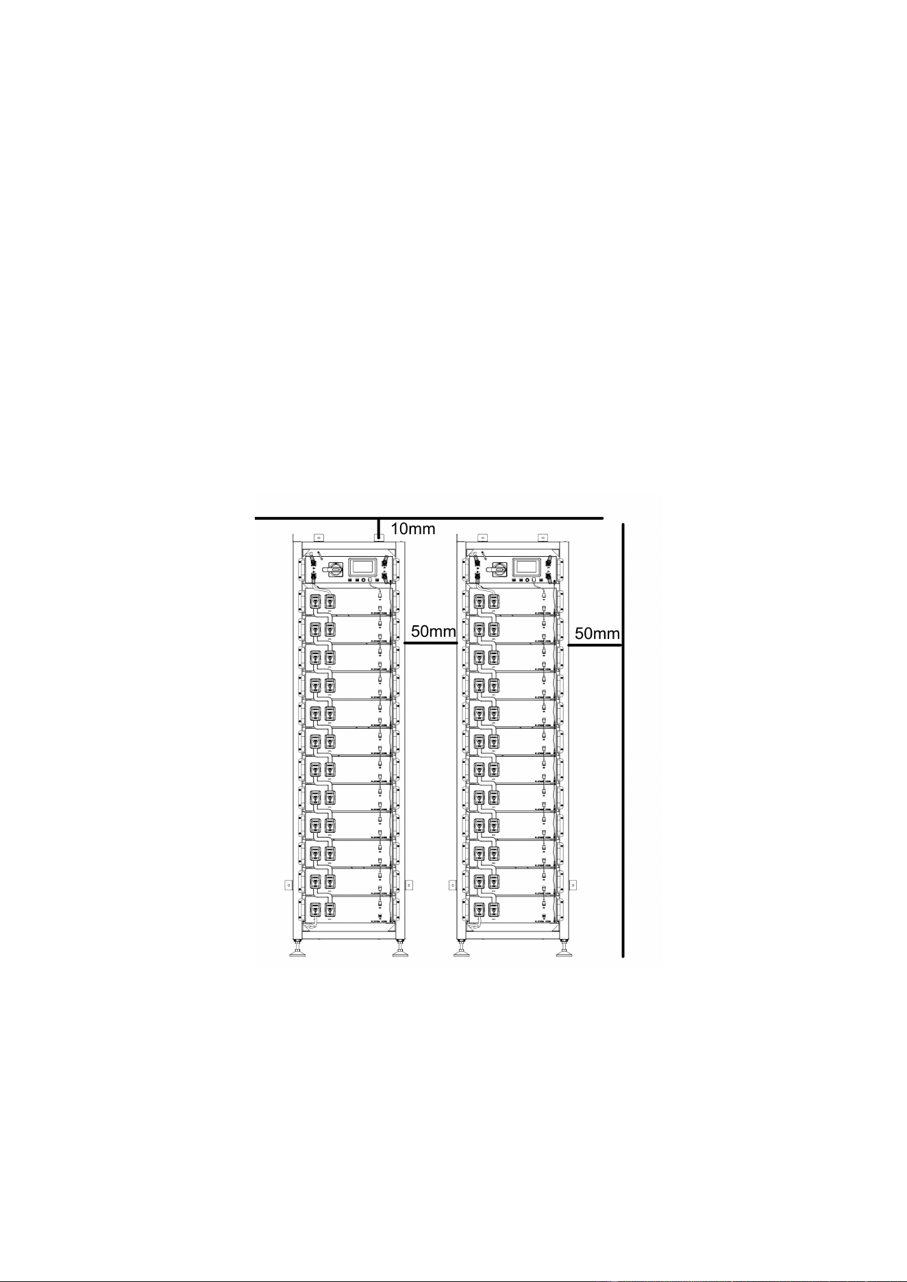
Minimum product installation distance
The minimum distance to the surrounding building when the battery is installed is
10mm, and the minimum distance between the two products is 50mm.
Compliance with the specifications in this manual is also part of proper use.
The use of the OHR-100 system is prohibited in the following circumstances:
• Mobile use on land or in the air (use on water only with the manufacturer's consent and with
the manufacturer's written consent).
• Used in medical devices.
• Used as a UPS system.
7

1.7 Requirements for Installation Personnel
All work shall comply with local applicable regulations and standards.
The installation of OHR-100 can only be completed by electricians with the following qualifications:
• Trained in dealing with hazards and risks associated with the installation and operation of electrical
equipment, systems, and batteries.
• Trained on installation and debugging of electrical equipment.
• Understanding and complying with the technical connection conditions, standards, guidelines,
regulations, and laws applicable.
• Knowledge of handling lithium-ion batteries (transportation, storage, disposal, hazard source).
• Understanding and complying with this document and other applicable documents.
8
2. Safety
2.1 Safety rules
To avoid property damage and personal injury, the following rules shall be followed when working on
the hazardous live parts of the battery energy storage system:
• It is available for use.
• Ensure that it will not restart.
• Make sure there is no voltage.
• Grounding protection and short circuit protection
• Cover or shield adjacent live parts.
2.2 Safety information
Part damage or short circuit may cause electric shock and death. A short circuit can be caused by
connecting battery terminals, resulting in current flow. This type of short circuit shall be avoided
under any circumstances. For this reason, follow these instructions:
• Use insulated tools and gloves.
• Do not put any tools or metal parts on the battery module or high-voltage BMS box.
• When operating the battery, be sure to remove watches, rings, and other metal objects.
• Do not install or operate this system in explosive or high-humidity areas.
• When working on the energy storage system, first turn off the charging controller, then the battery,
and ensure that they are not turned on again.
Improper use of the battery energy storage system can lead to death. The use of the battery energy
storage system beyond its intended use is not allowed, because it may cause great danger.
Improper handling of the battery energy storage system can cause life-threatening risks, serious
injury or even death.
Warning! Improper use can cause damage to the battery cell.
• Do not expose the battery module to rain or soak it in liquid.
• Do not expose the battery module to a corrosive environment (such as ammonia and salt).
• The battery energy storage system shall be debugged no later than six months after delivery.
3. Transport to the end customers
3.1 Provisions on Shipping of Battery Modules:
It is necessary to comply with the relevant regulations and provisions on roads for shipping lithium-ion
products in the corresponding countries.
It is prohibited to smoke in the vehicle during transportation or in the vicinity during
loading and unloading.
The dangerous goods transport vehicles shall meet relevant regulations concerning road
transportation and shall be equipped with two tested CO2 fire extinguishers.
It is forbidden for the freight forwarder to open the outer package of the battery module.
Use only approved lifting equipment to move the battery cabinet system. Use only the hanging lug on
the top of the battery cabinet as the connection point. When lifting, the angle of the sling must be at
least 60° .
Improper vehicle transportation can cause injury. Improper transportation or improper
9
transportation locks may cause the load to slip or overturn, resulting in injury. The cabinet shall be
placed vertically to prevent it from sliding in the vehicle, and a fixing belt shall be used.
A tilting of the battery rack may cause injury. The maximum weight of a single battery rack
of OHR-100 can reach 640 kg. When tilted, they may overturn, causing injury and damage.
Ensure that the battery cabinet is on a stable surface and that it does not tilt due to load or force.
The battery energy storage system can be damaged, if not properly transported. The battery
module can only be transported vertically. Note that these parts may be top-heavy.Failure to follow
this instruction may result in damage to the part.
During transportation, the battery storage rack may be damaged when it is installed with
the battery module. The battery storage rack is not designed to be transported with the installed
battery modules. Always transport the battery module and the battery rack separately. Once the
battery module is installed, do not move the battery rack, and do not lift it by a lifting device.
If possible, do not remove the transport packaging before arrival at the installation site.
Before removing the transport protector, check if the transport packaging is damaged, and check the
impact indicator on the outer packaging of the battery converter. If the impact indicator is triggered,
the possibility of transport damage cannot be ruled out.
Wear safety shoes to avoid the danger of injury. When transporting the battery rack and
battery module, their parts may be crushed due to their heavy weight. Therefore, all persons involved
in transportation must wear safety shoes with toe caps. Please observe the safety regulations for
Improper transportation of battery modules may cause injury. The single battery module
weighs 45.8 kg. If it falls or slips, it may cause injury. Only use suitable transport and lifting equipment
to ensure safe transport.
transportation at the end customer's site, especially during loading and unloading.
During transportation and installation of unpacked battery storage cabinets, the risk of
injury increases, especially on sharp metal panels. Therefore, all personnel involved in transportation
and installation must wear protective gloves.
The battery module can only be transported in an upright position. Please note that the battery
rack may be very top-
The maximum weight of a single rack of OHR-100 can reach 640kg. We suggest that at least
2-3 people work together to install the battery rack. The lifting device is helpful for heavy parts, and
the pulley or cart for light parts. Be careful not to damage the case. The number of battery modules
stacked shall not be more than 12.
Check whether the delivery is complete.
3.2 Permissible and Impermissible Storage Positions of a Packaged
Battery Module
heavy.
10
WARNING! Possible damage to the building due to static
4.1
4. Description and installation of OHR-100 battery
Installation Precautions
overload
1. The total weight of the battery storage system is kgs. Ensure that the installation site has sufficient
bearing capacity.
2. When selecting the installation site, consider the transportation route and necessary site cleanup.
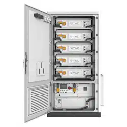
4.2 OHR-100 Product Description
OHR-100 is a high-voltage lithium-ion battery system. It provides a reliable backup power supply for
supermarkets, banks, schools, farms and small factories to smooth the load curve and achieve peak
load transfer. It can also improve the stability of renewable systems and promote the application of
renewable energy.
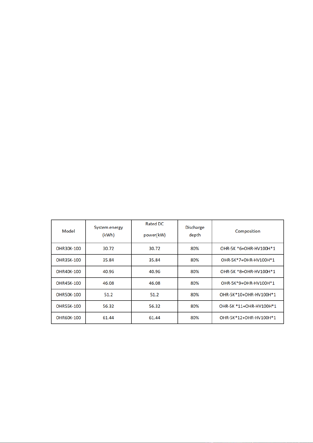
It is characterized by high integration, good reliability, long service life, wide working temperature
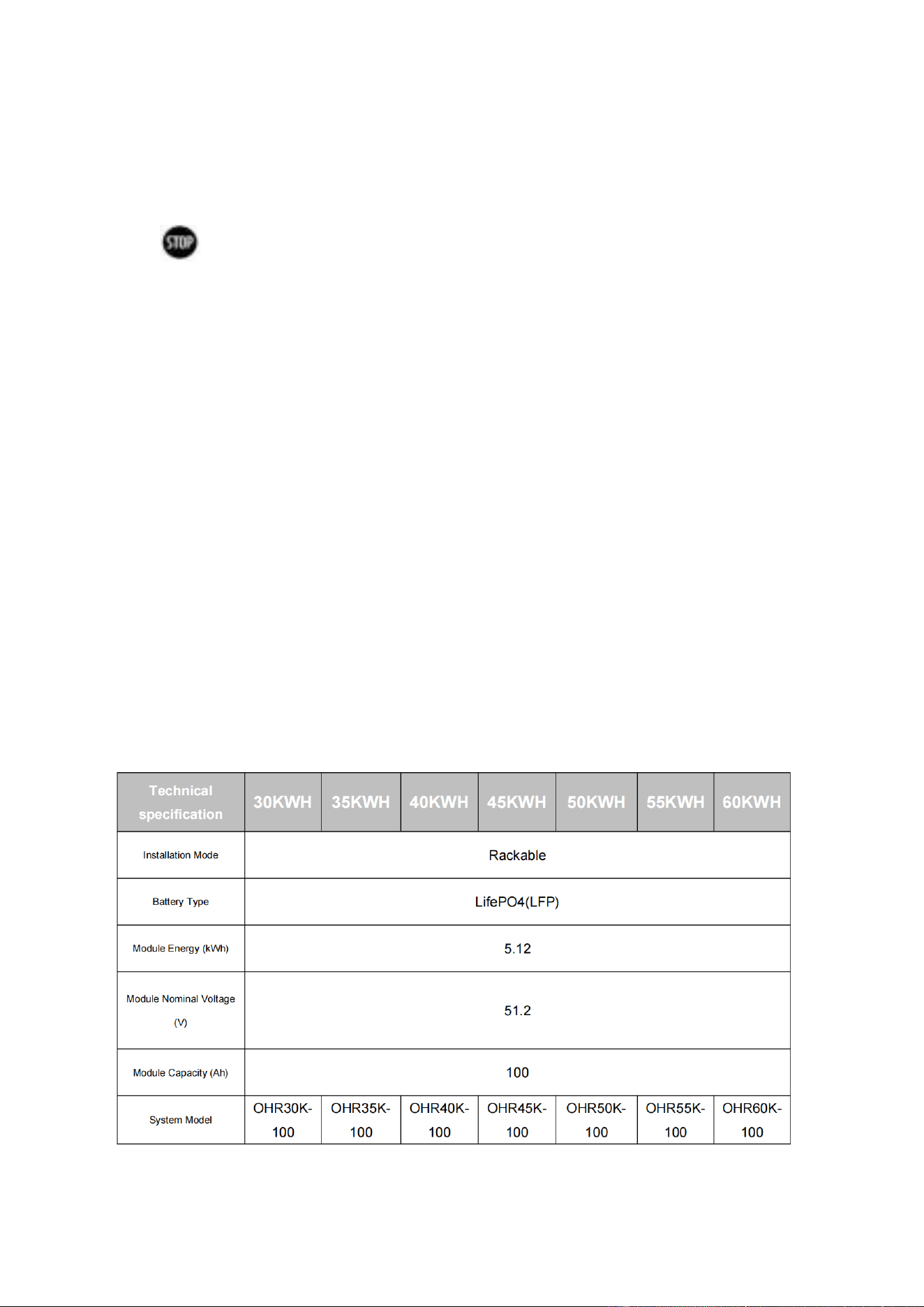
range, etc. The battery energy storage system is modular. Each battery module has a capacity of 5.12
kWh. It can support up to 12 battery modules in series. Its total energy can be expanded from 30.72
kWh to 61.44 kWh.
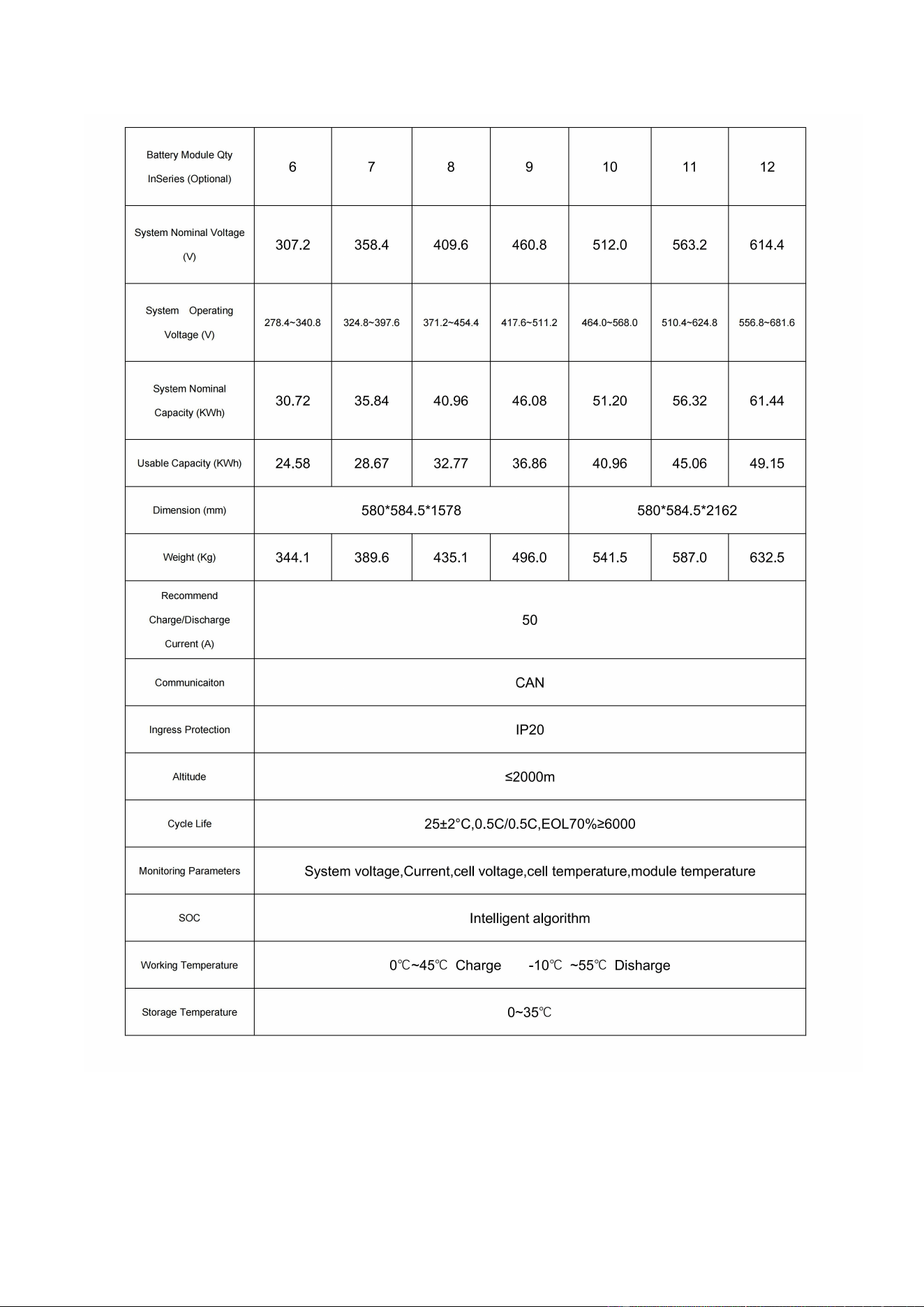
4.3 Technical Data
11
12
4.4. Preparation
4.4.1 Tools required
① PHILIP2# crosshead screwdriver;
② 10mm hexagon socket
③ 24mm wrench
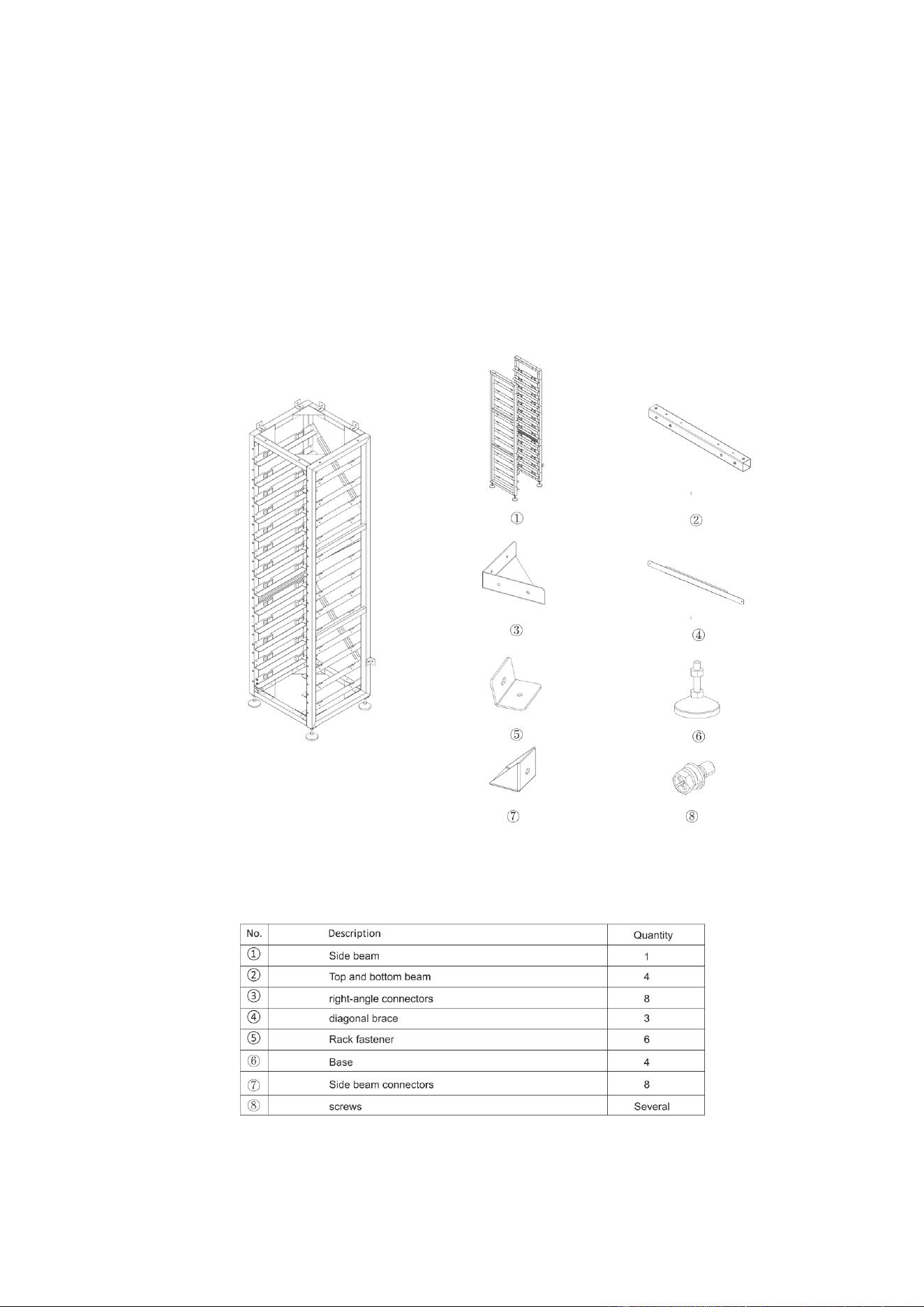
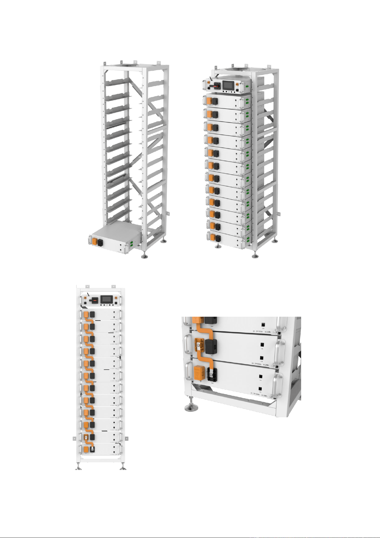
4.4.2 OHR-3U-HRACK Parts description
13
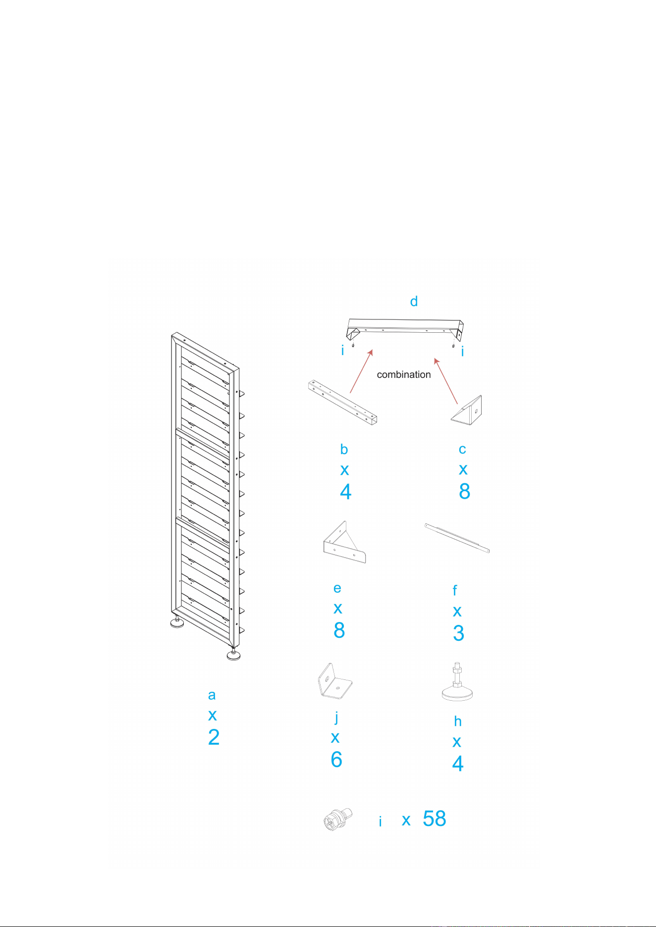
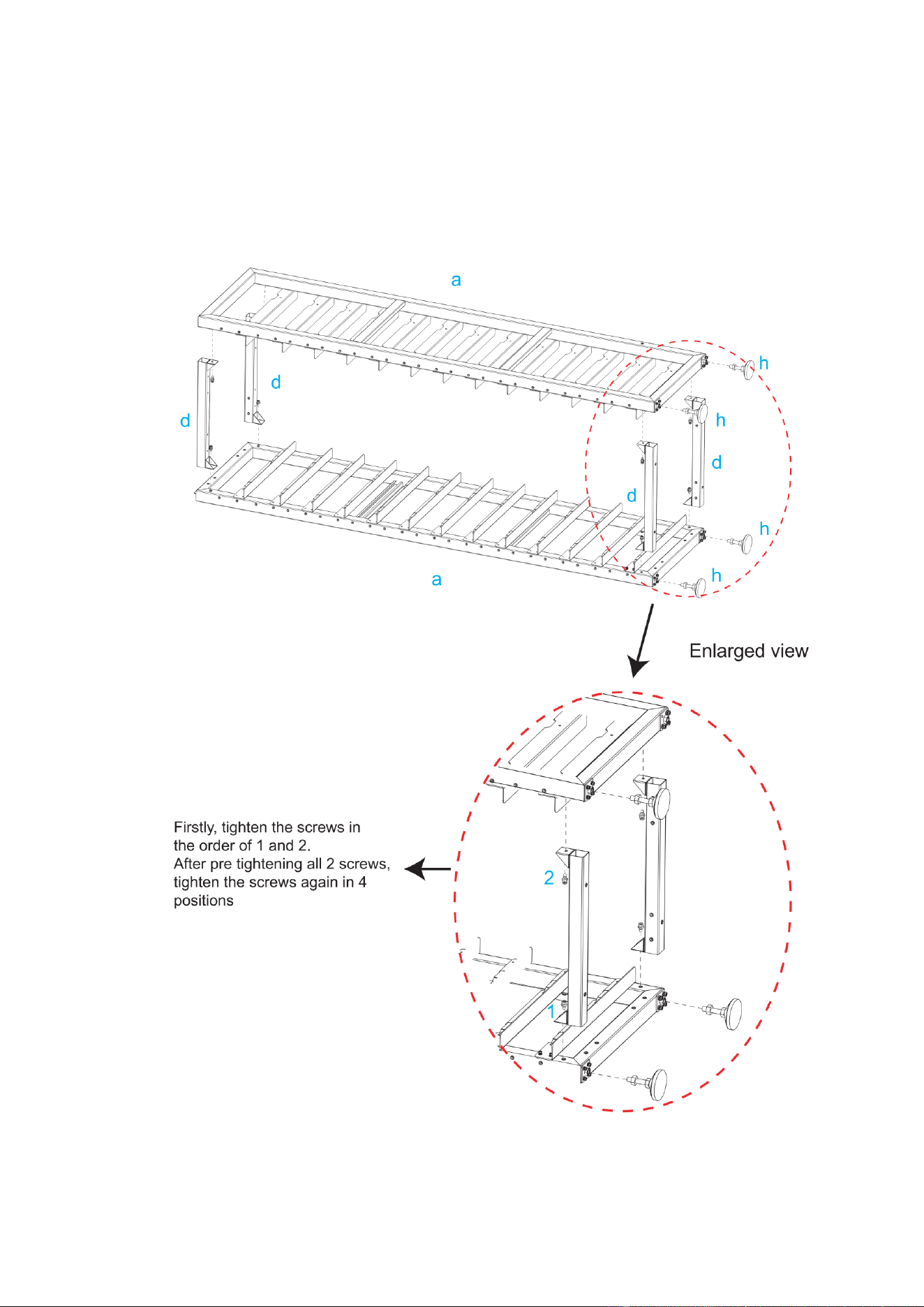
4.4.3 Installation of Rack
①Take out two side beams and four Connect sorghums, connect the four Connect sorghums to the
side beams, and then fix the side beams and Connect sorghums with screws. After fixing, take out
eight Transverse connectors and connect them to the side beams, and fix the side beams and
Transverse connectors with screws
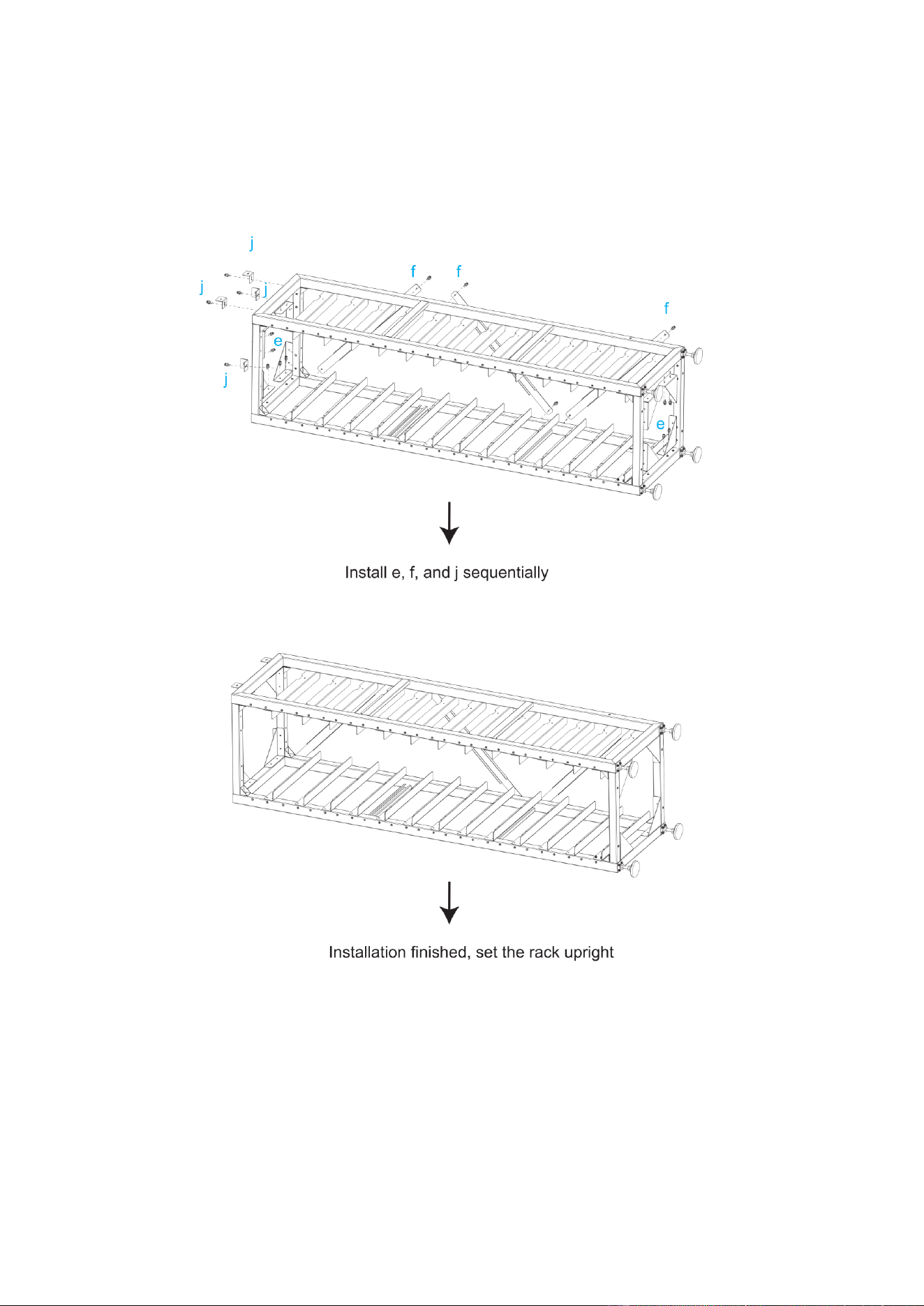
②The left and right diagonal braces are fixed on both sides of the beam with round head hexagon
combination screws and hexagon wrenches.
③Screw the base into the bottom plate and secure it with hexagonal wrench or by hand.
④When installation is complete, stand the rack up
14
15
16
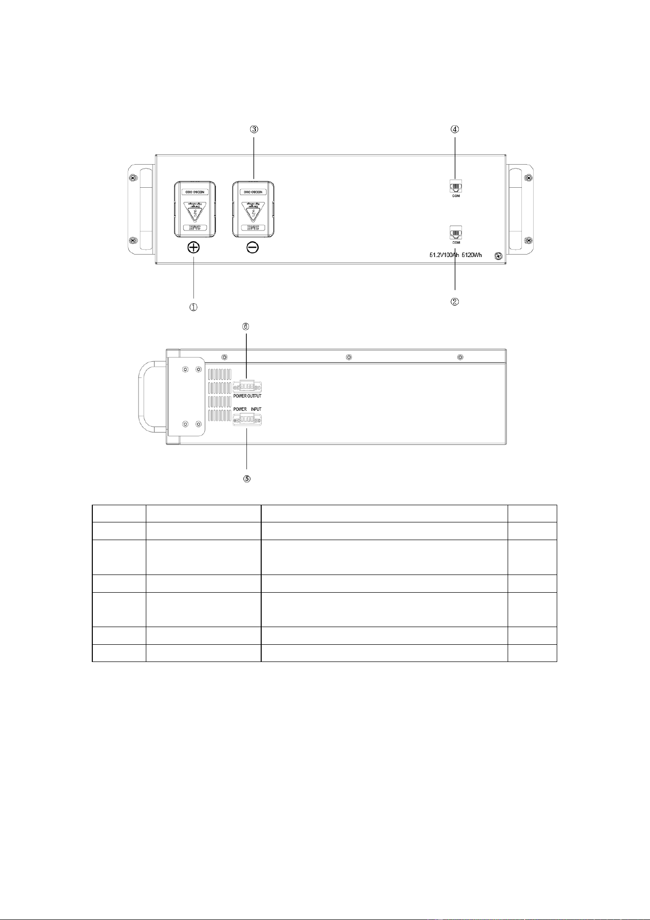
4.5 Description of Battery Module
NO. Name Description. Position
①
B+ Battery module positive pole (orange) Front
②
COM
Connection position of battery module
communication and power supply output.
Front
③
B- Battery module negative pole (black). Front
④
COM
Connection position of battery module
communication supply input.
Front
⑤
POWER INPUT Connect the fan power input line. side
⑥
POWER OUTPUT Connect the fan power output line. side
17
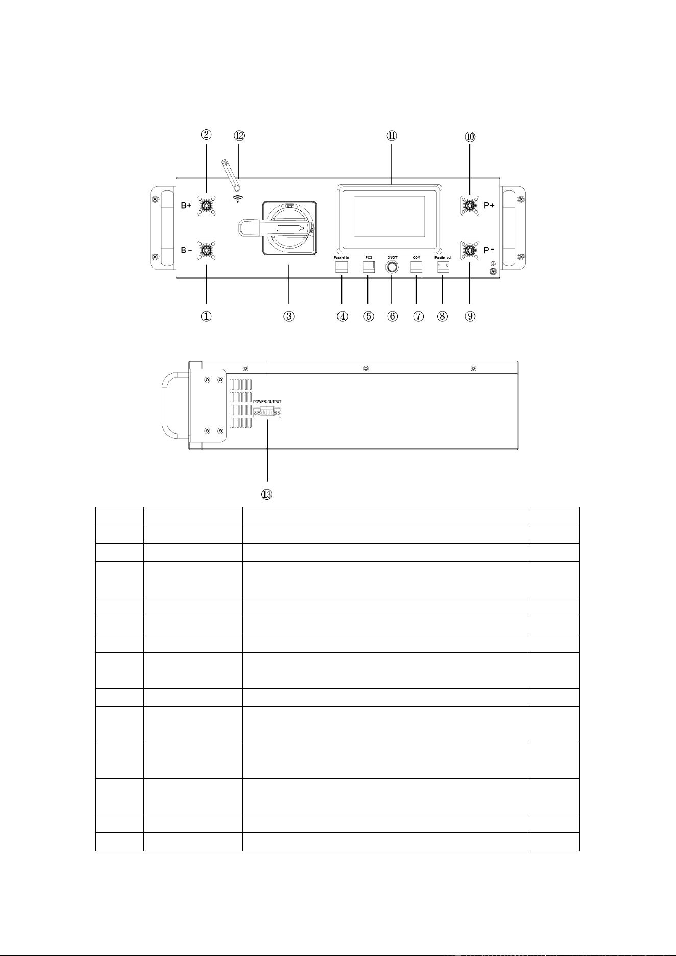
4.6 Description of high-voltage BMS box
NO. Name Description. Position
①
B- High voltage BMS box module negative pole (black). Front
②
B+ High voltage BMS box module positive pole (orange) Front
③
DC circuit breaker
Used to manually control the connection between the
battery rack and external devices.
Front
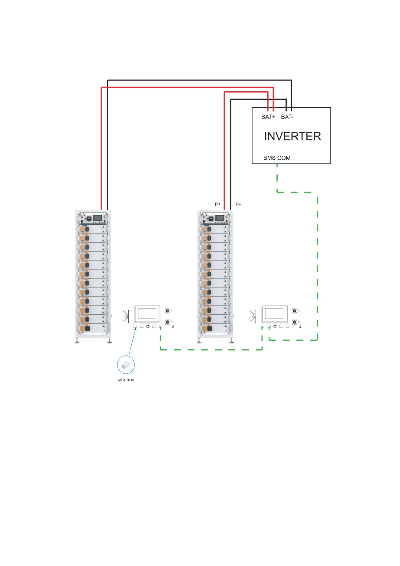
④
Parallel in Parallel communication input port Front
⑤
PCS
Inverter communication port,PIN4:CANH;PIN5:CANL;
Front
⑥
ON/OFF BMS start button and Green indicator light Front
⑦
COM
Communication port between battery and High voltage
BMS
Front
⑧
Parallel out Parallel communication output port Front
⑨
P-
Connect the high-voltage BMS box to the negative pole
of the inverter
Front
⑩
P+
Connect the high-voltage BMS box to the positive pole
of the inverter
Front
⑪
Human-machine
interface (HMl)
Display some important battery information. Front
⑫
Wifi High voltage BMS box WiFi signal antenna Front
⑬
Power output Connect the fan power output line. side
18
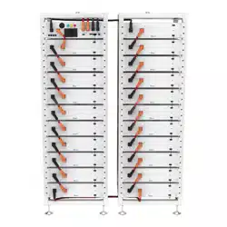
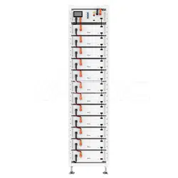
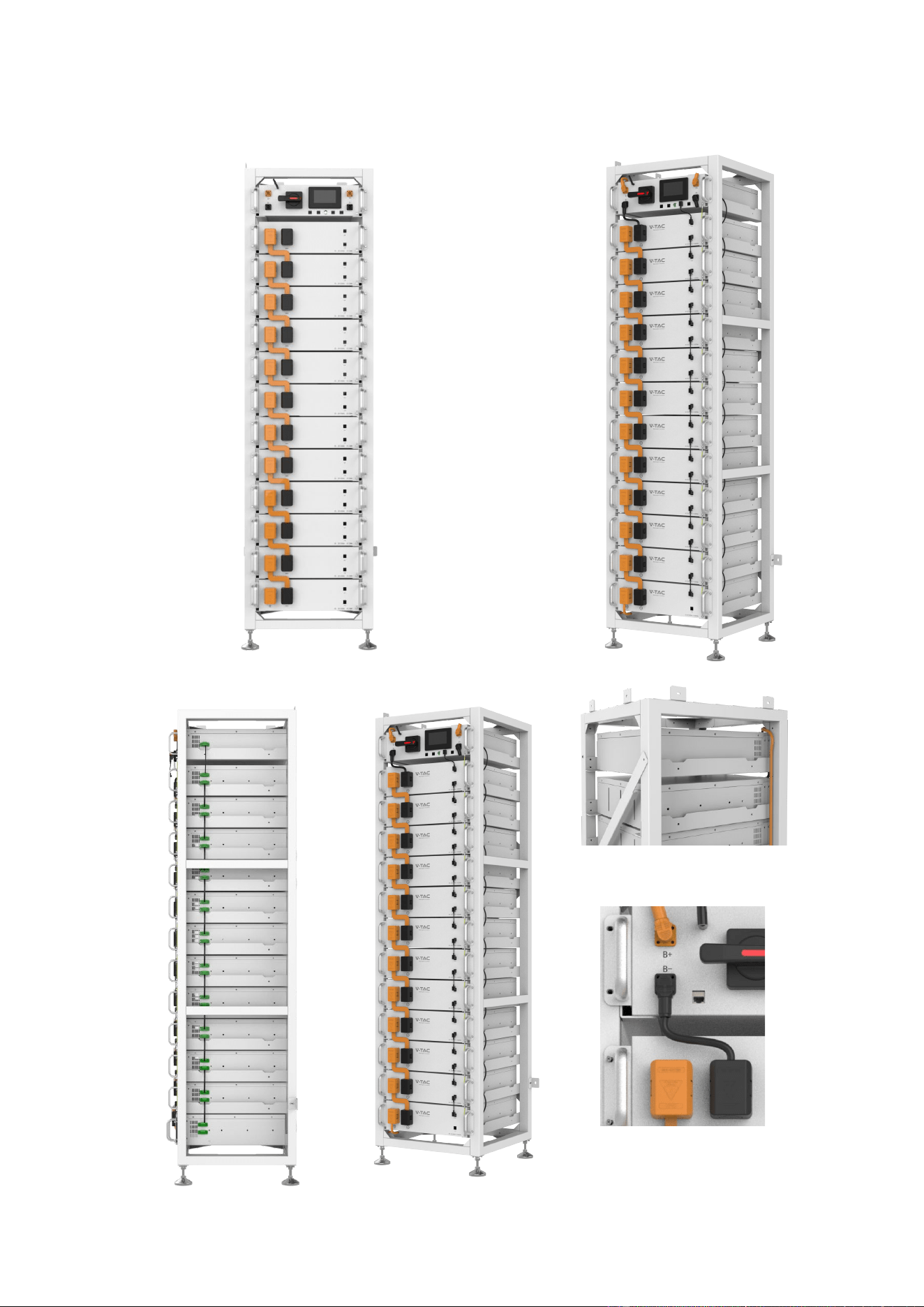
4.7 Description of Battery Module in Rack
19
20
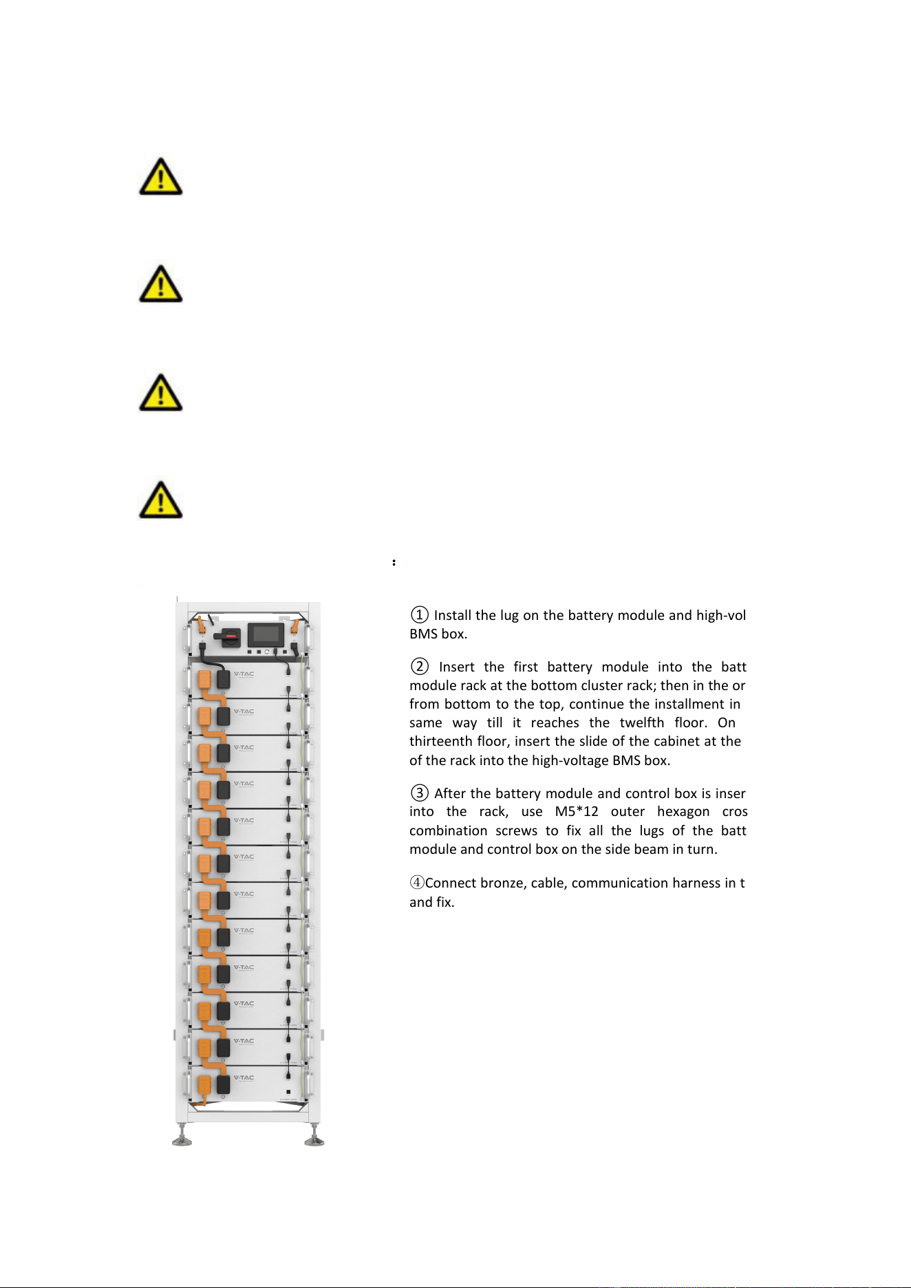
4.8 Installation of the Battery Module to the Rack
Insufficient or no grounding may cause an electric shock. Device malfunctions, and
insufficient or no grounding may cause device damage and life-threatening electric shocks.
Note: Before installing the battery, please turn the manual switch of the high-voltage
control box to the off position.
CAUTION
Note the allowable installation modes
CAUTION
Remember that this battery is heavy! Please be careful when lilting out from the package.
:
① Install the lug on the battery module and high-voltage
BMS box.
② Insert the first battery module into the battery
module rack at the bottom cluster rack; then in the order
from bottom to the top, continue the installment in the
same way till it reaches the twelfth floor. On the
thirteenth floor, insert the slide of the cabinet at the top
of the rack into the high-voltage BMS box.
③ After the battery module and control box is inserted
into the rack, use M5*12 outer hexagon cross
combination screws to fix all the lugs of the battery
module and control box on the side beam in turn.
④Connect bronze, cable, communication harness in turn,
and fix.
21
22
23
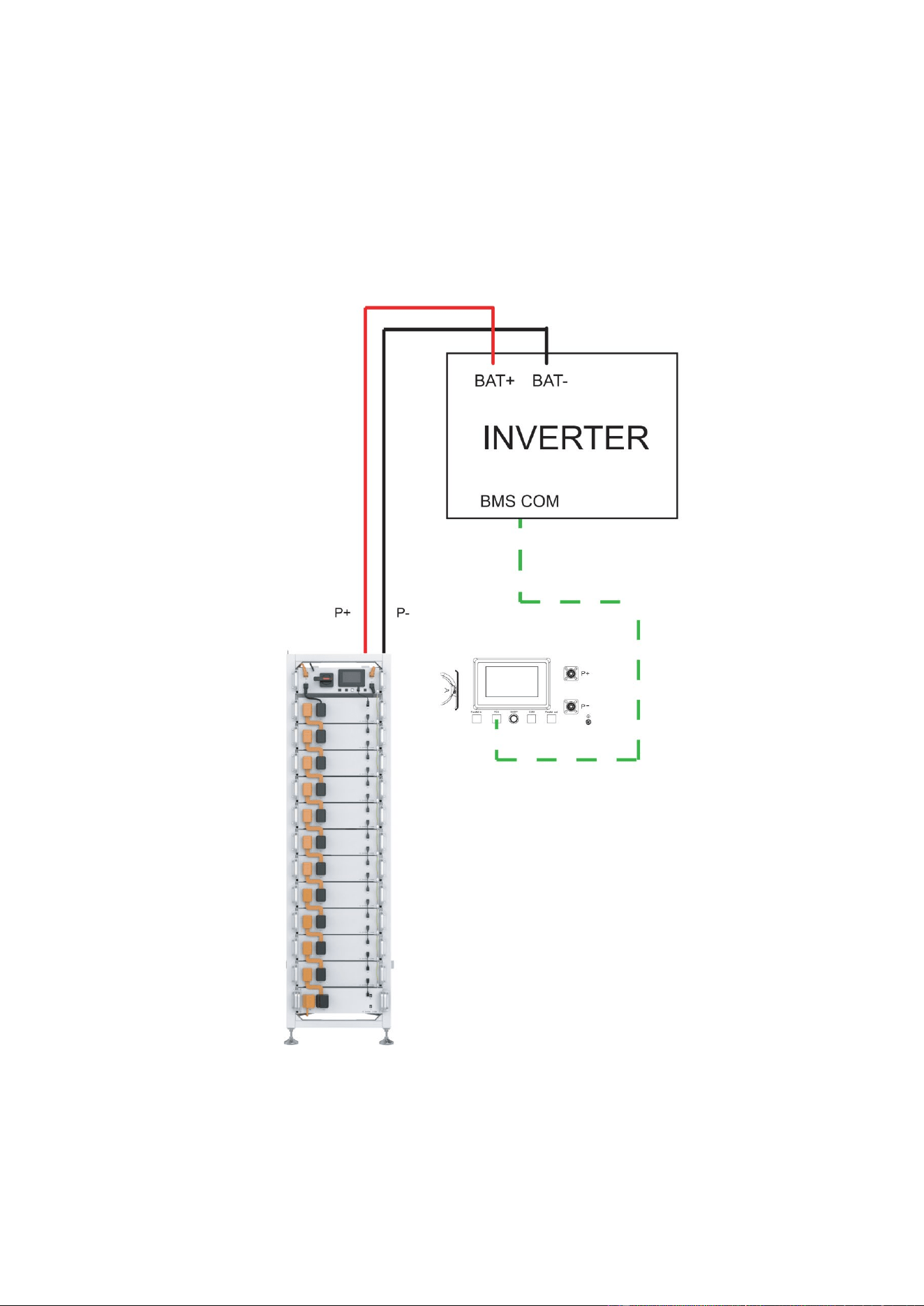
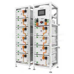
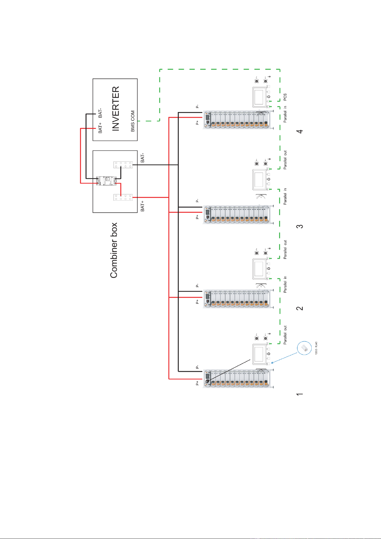
4.9 Battery cluster connected to inverter
24
25
26

4.10 System startup and shutdown
Startup procedure
① After connecting the battery cables, press the DC circuit breaker on the high-voltage BMS
box to turn OFF to ON.
② Press the start button and wait for the screen to light up.
③Turn on the circuit breaker after the battery pack is started.
④ Complete boot.
Shutdown procedure
① Press the start button again and wait for the screen to go off.
② Press the DC circuit breaker ON the high pressure control box and set the "ON" to the
"OFF" position.
③Turn off the circuit breaker after the battery pack is closed.
④Complete shutdown.
Description of external circuit breakers between inverter and battery system
27
5 OHR’S User Interface
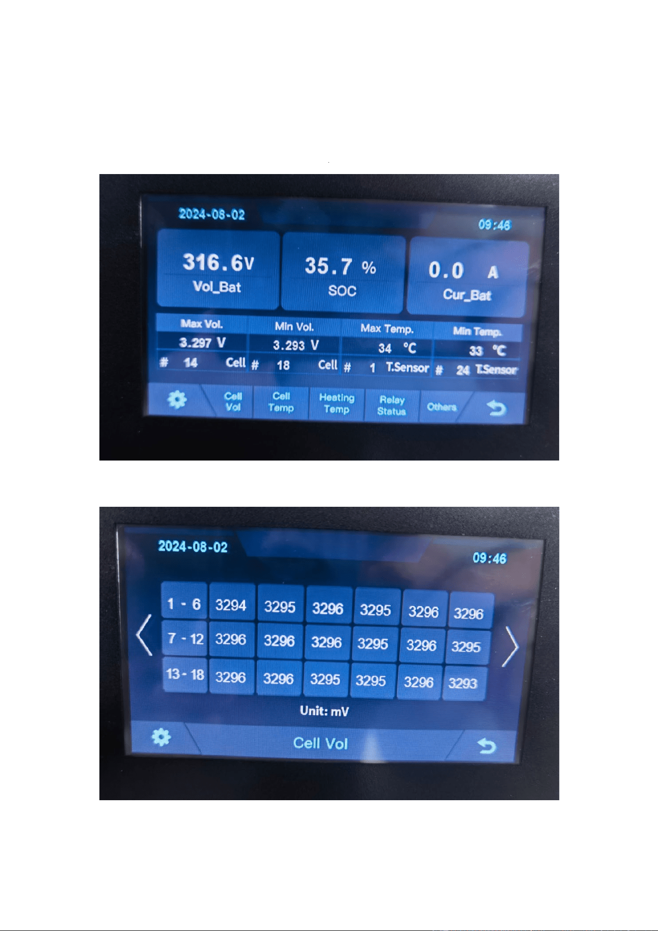
5.1 Main Interface
5.2 Cell Voltage
Fault display area
28
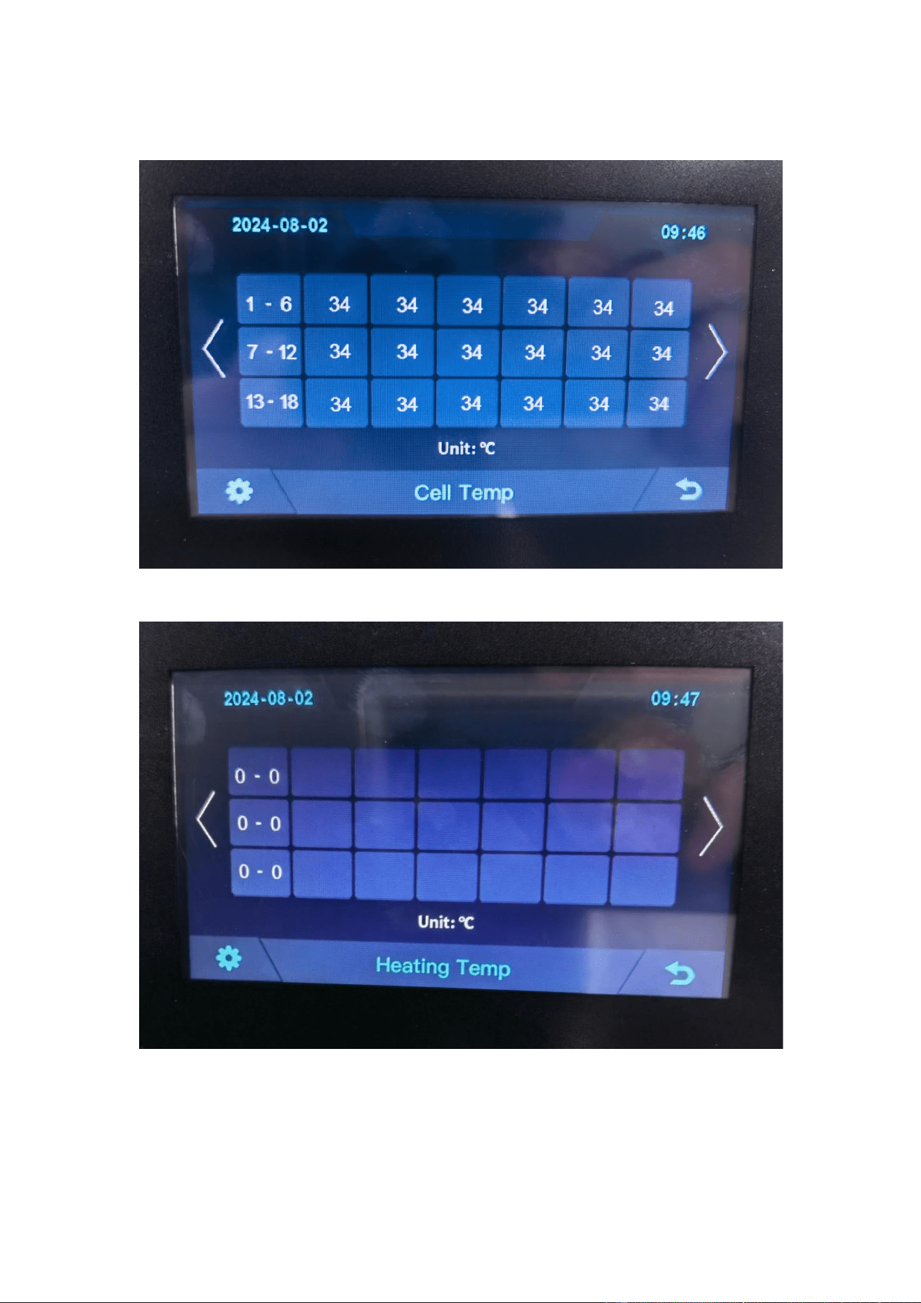
5.3 Cell Temperature
5.4 Heating Temperature
29
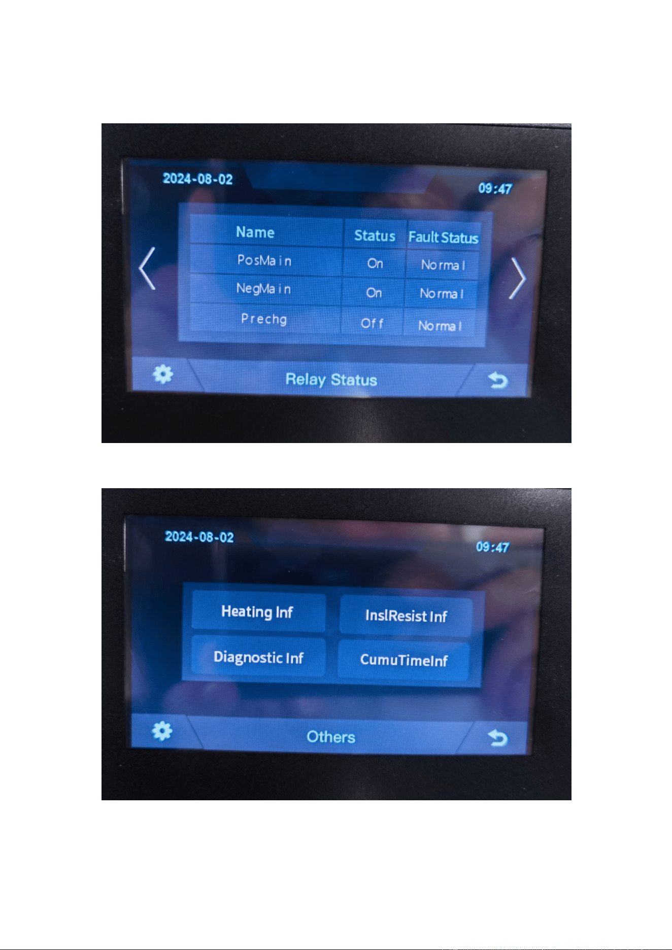
5.5 Relay Status
5.6 Other
30
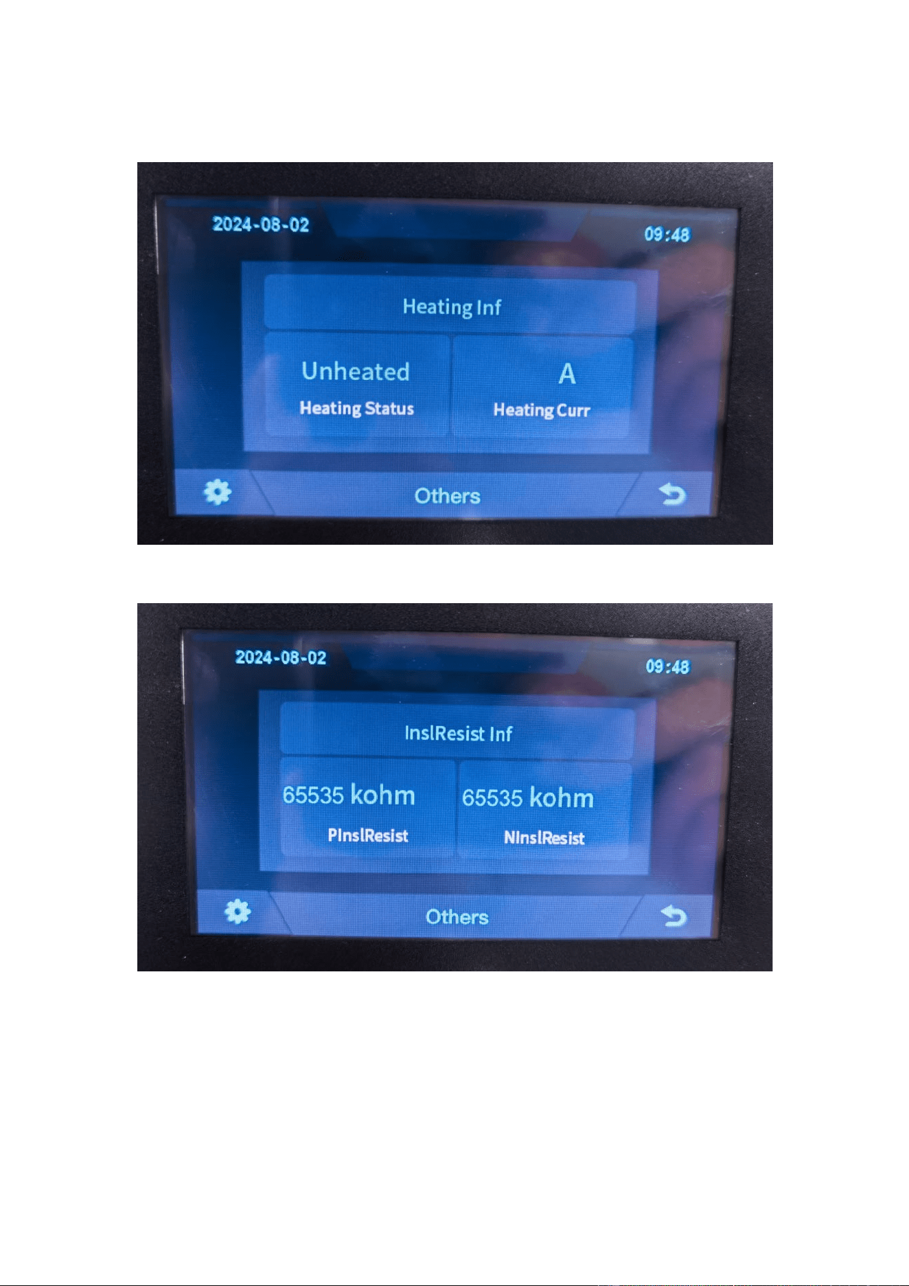
5.6.1 Heating Information
5.6.2 Insulation Resistense
31
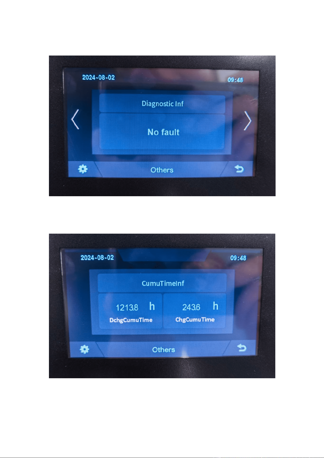
5.6.3 Diagnostic Information
5.6.4 Cumulative Time Information
32
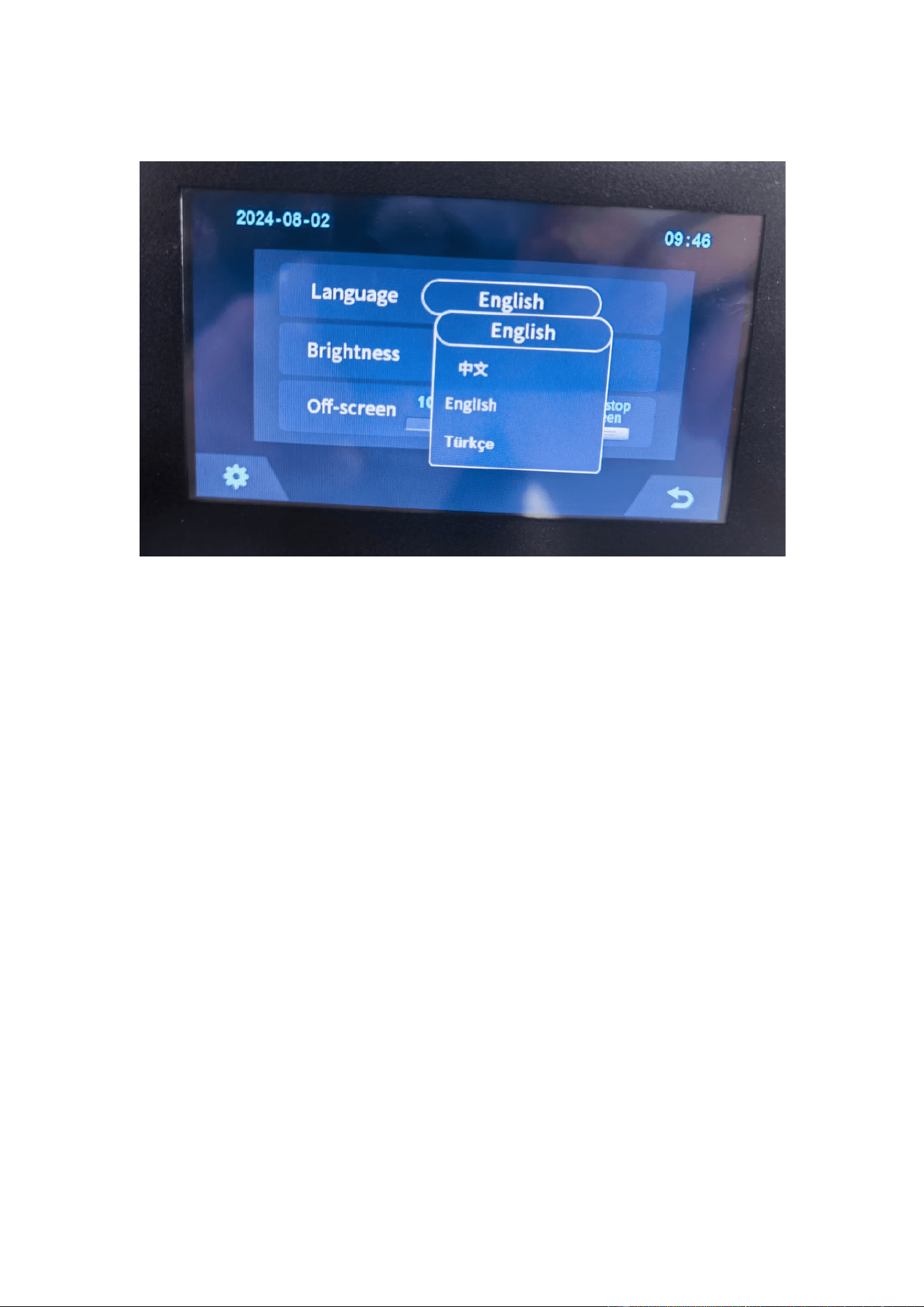
5.7 Set Up
33
6 Xiaodan Energy Storage App
6.1. App download
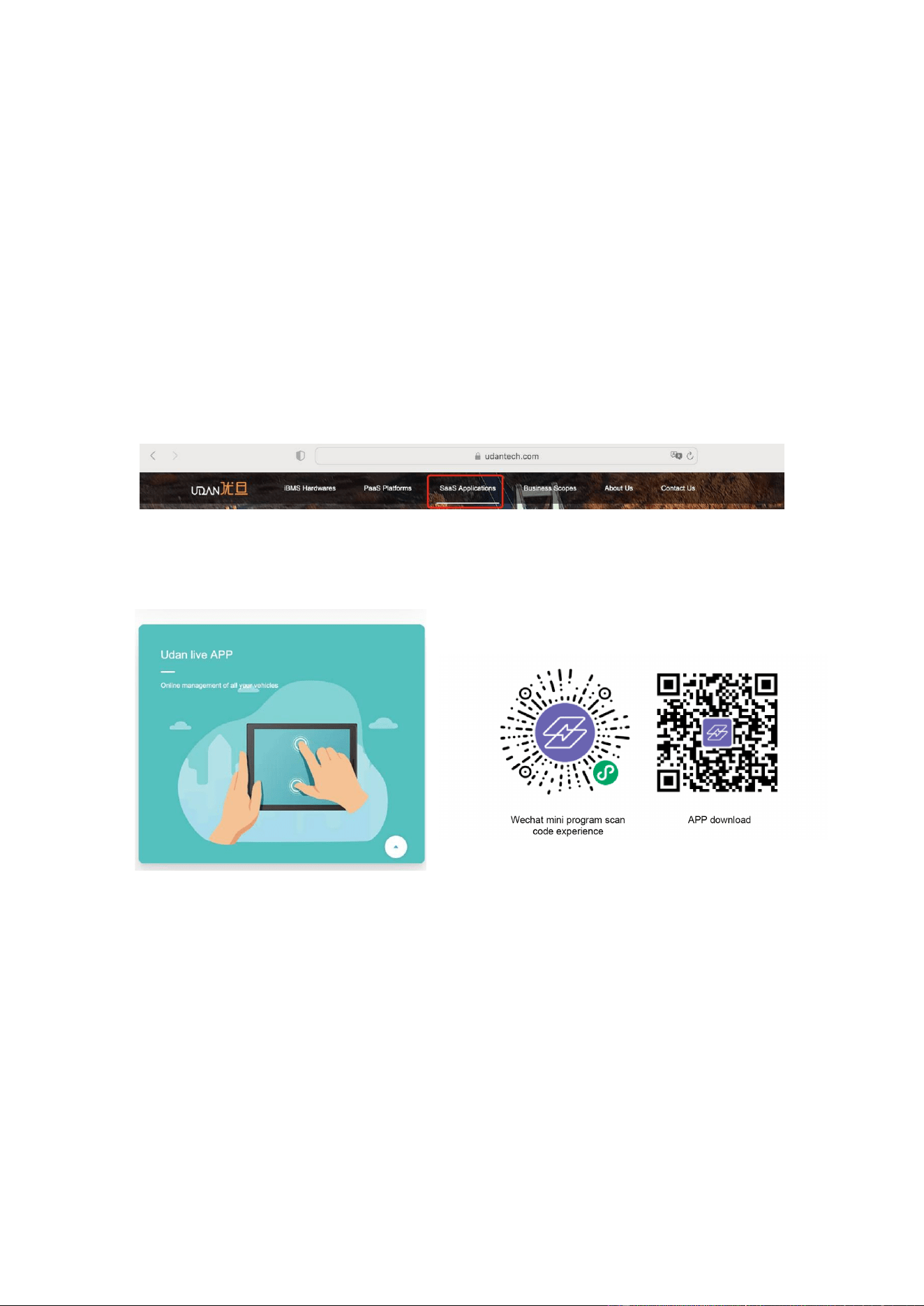
6.1.1 Android version
1.
Enter the official website of Youdan Technology https://www.udantech.com/#/ ,
click on the "SAAS Application" column in the top navigation bar, pull down to the
mobile app application module, and you can see the mobile WeChat Mini Program
and App application download.
6.1.2 iOS version
Enter the mobile App Store, search for "Xiaodan Energy Storage", and you can
download and install it.
34

6.2. Log in and register
6.2.1 Log in
•
After opening the APP, enter the login interface to log in with your account.
•
Currently supports logging in through email accounts
35

6.2.2 Register
•
At the bottom of the login page, click the "Account Registration" button to enter
the registration process.
36
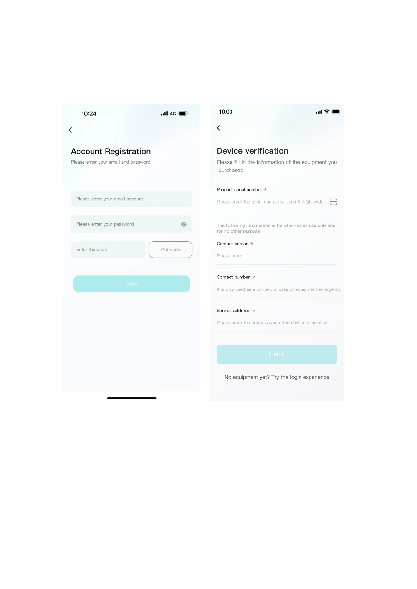
• Currently, you can register with an email account. After registration, you need to
go through the device verification process and enter the device SN code or device QR
code for identification.
6.2.3 Experience login
•
At the bottom of the login page, click the "Experience Login" button to experience
the app function without registration as a tourist.
37

6.3. Equipment distribution network
6.3.1 Overview
Device distribution network refers to connecting devices to the Cloud Computing
Platform to help users obtain real-time device data information.
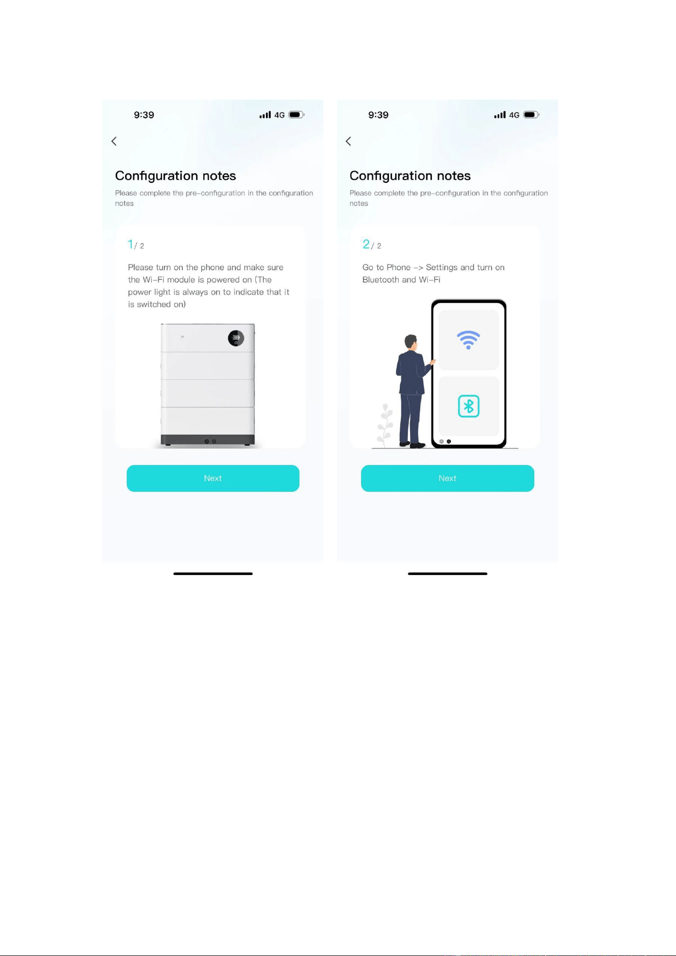
6.3.2 Distribution process
1.
Preparation before distribution: Ensure that the device is on , turn on the mobile
phone Bluetooth and wireless LAN functions.
38
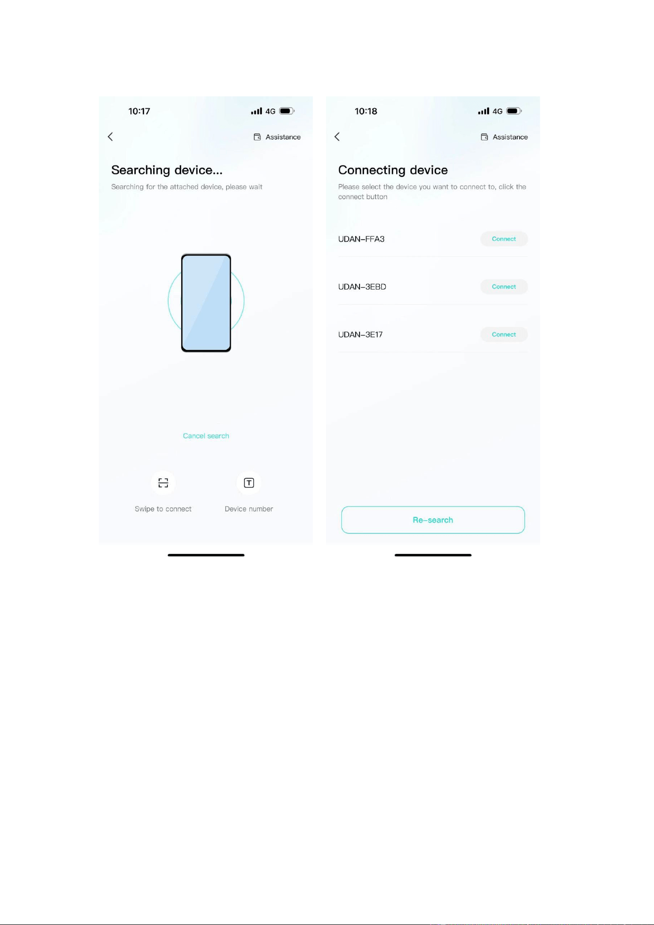
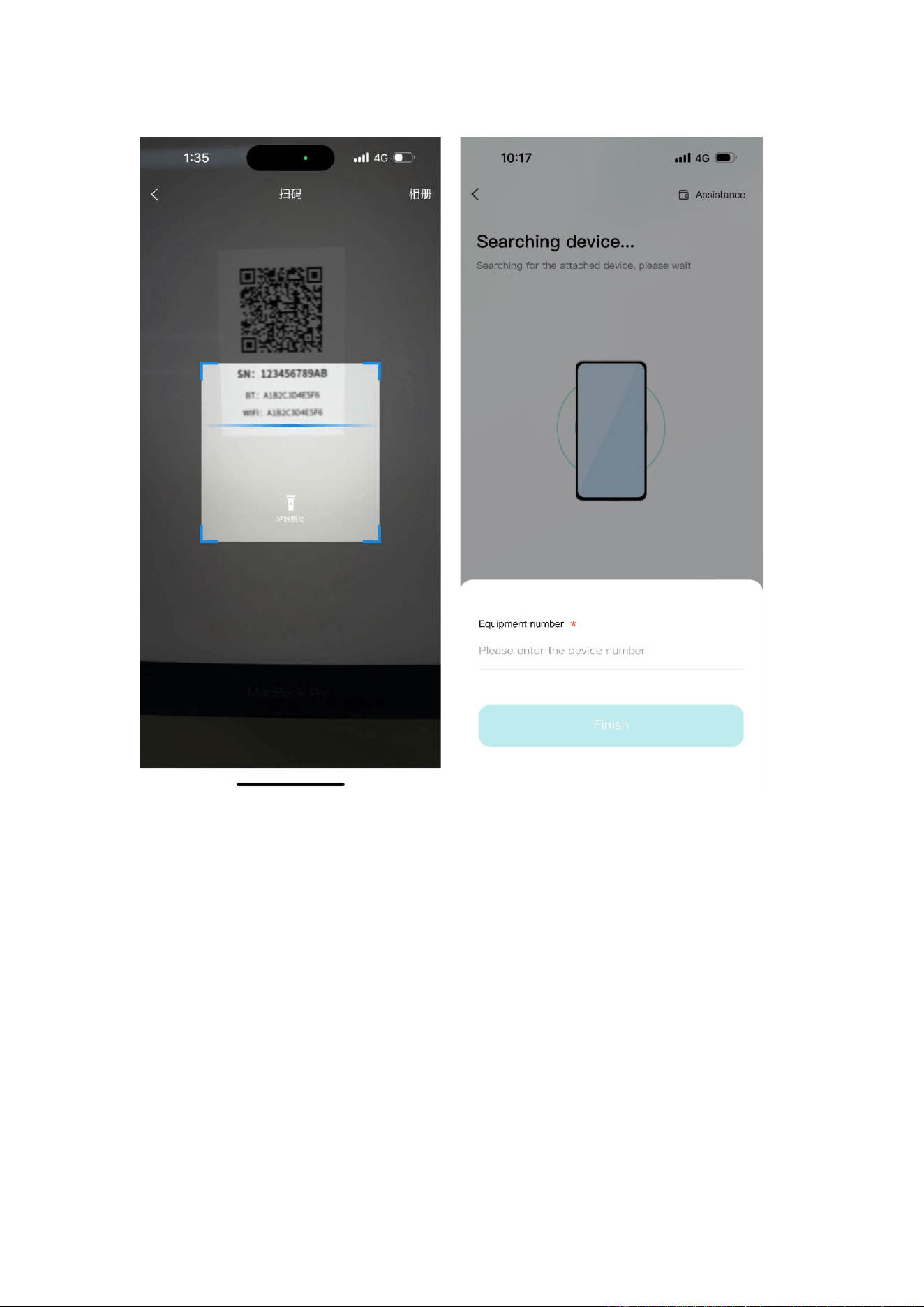
2.
Connected devices: The current App supports Bluetooth search, device
scanning, and manual input of SN code .
39
40
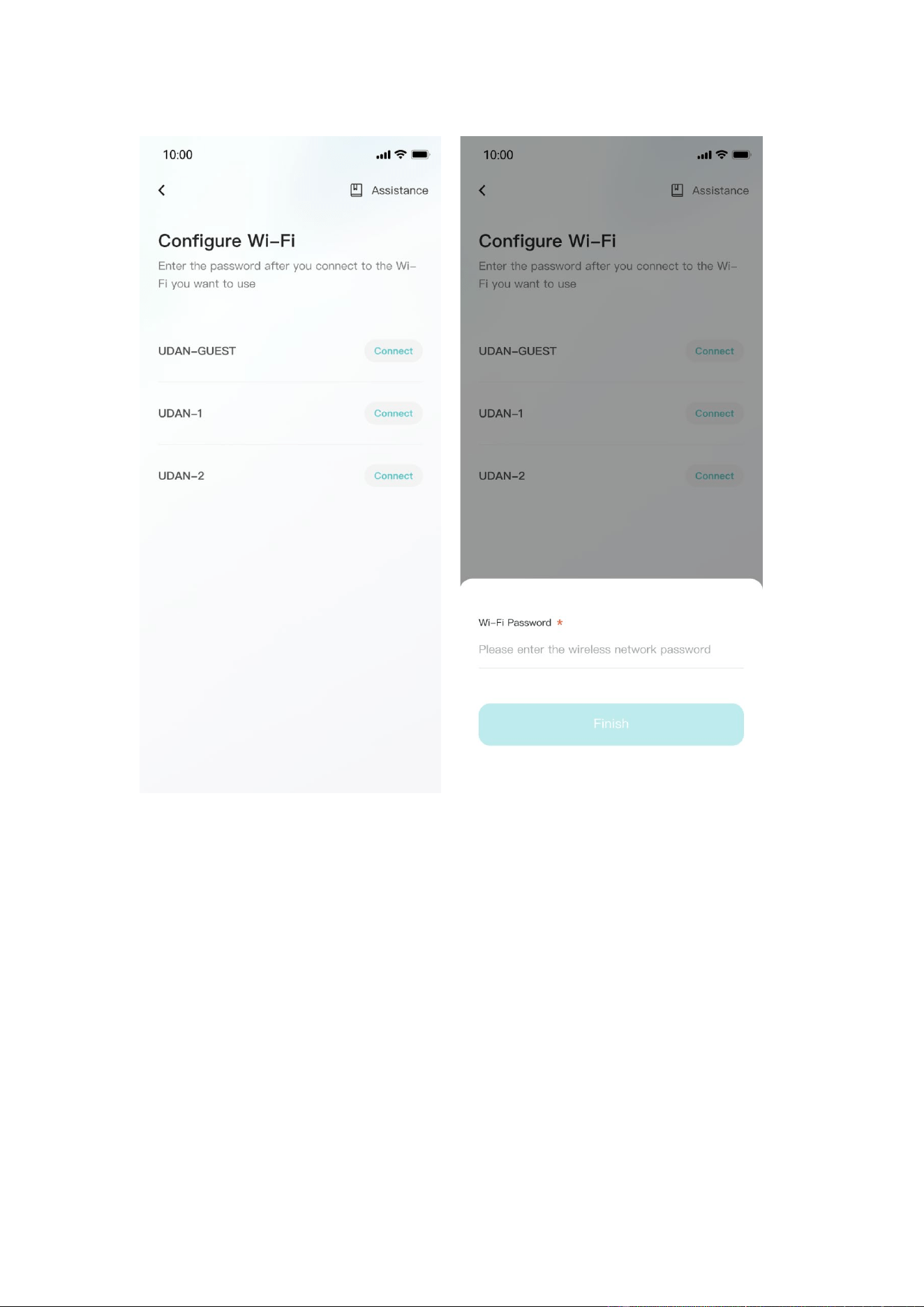
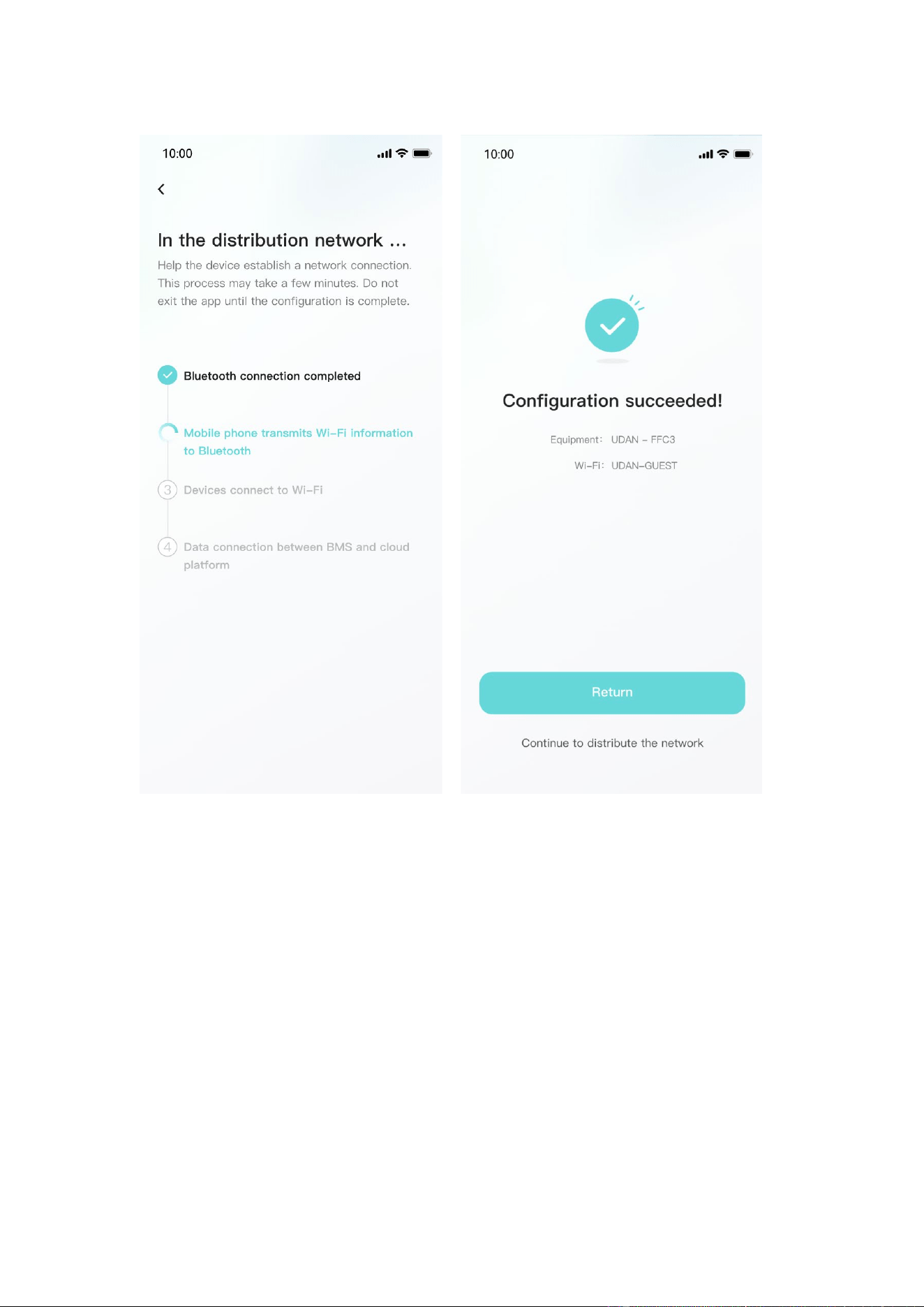
3.
Connect to WiFi: After the device is connected, enter the WiFi connection
process.
•
Select the WiFi you want to use and click the "Connect" button. Enter the WiFi
password and click the "Finish" button to distribute the network.
41
42
6.4. App page
6.4.1 Equipment
The device homepage is used to display the currently managed device information.
43
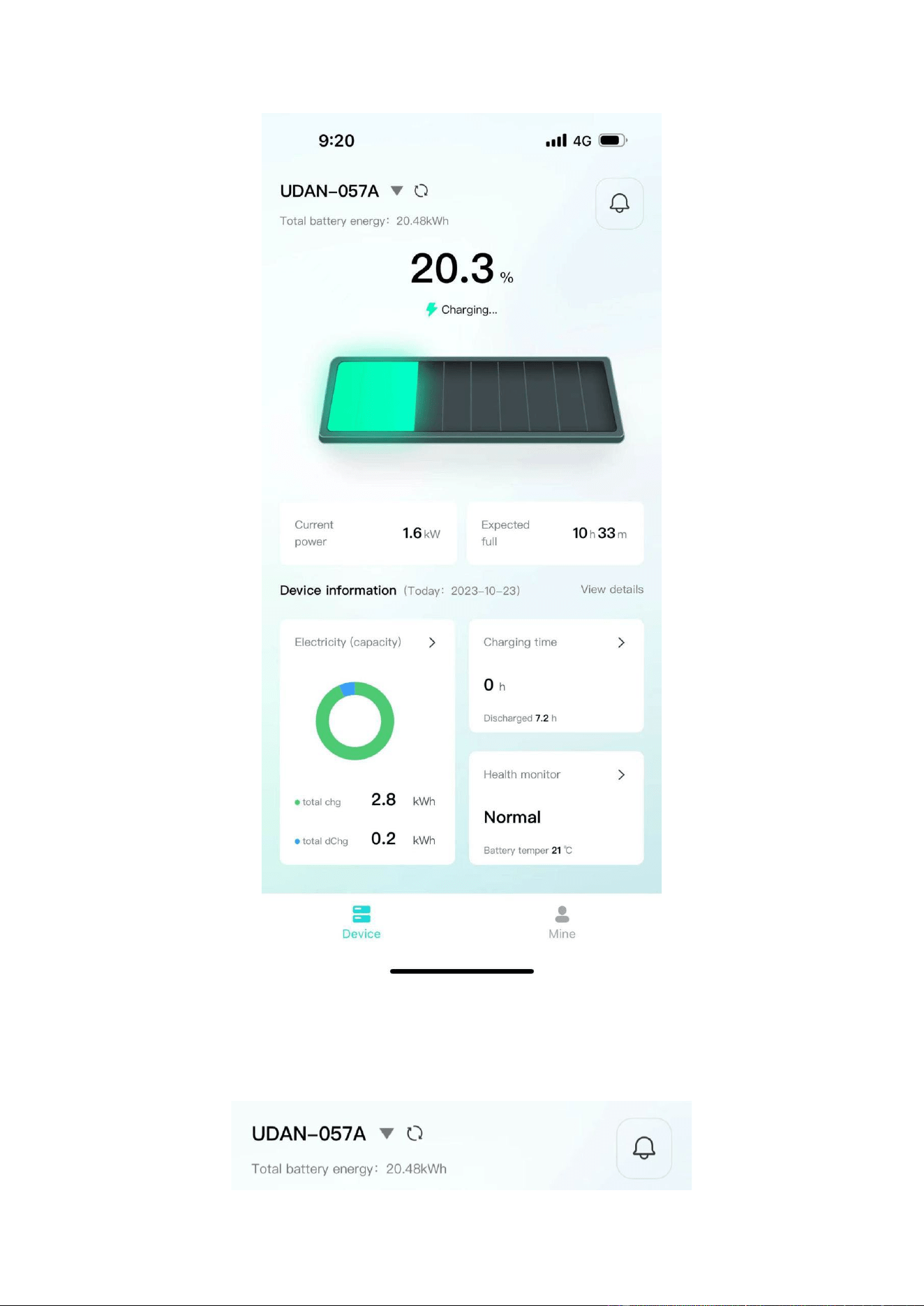
•
The top area displays the device name, battery energy, and message entry.
44
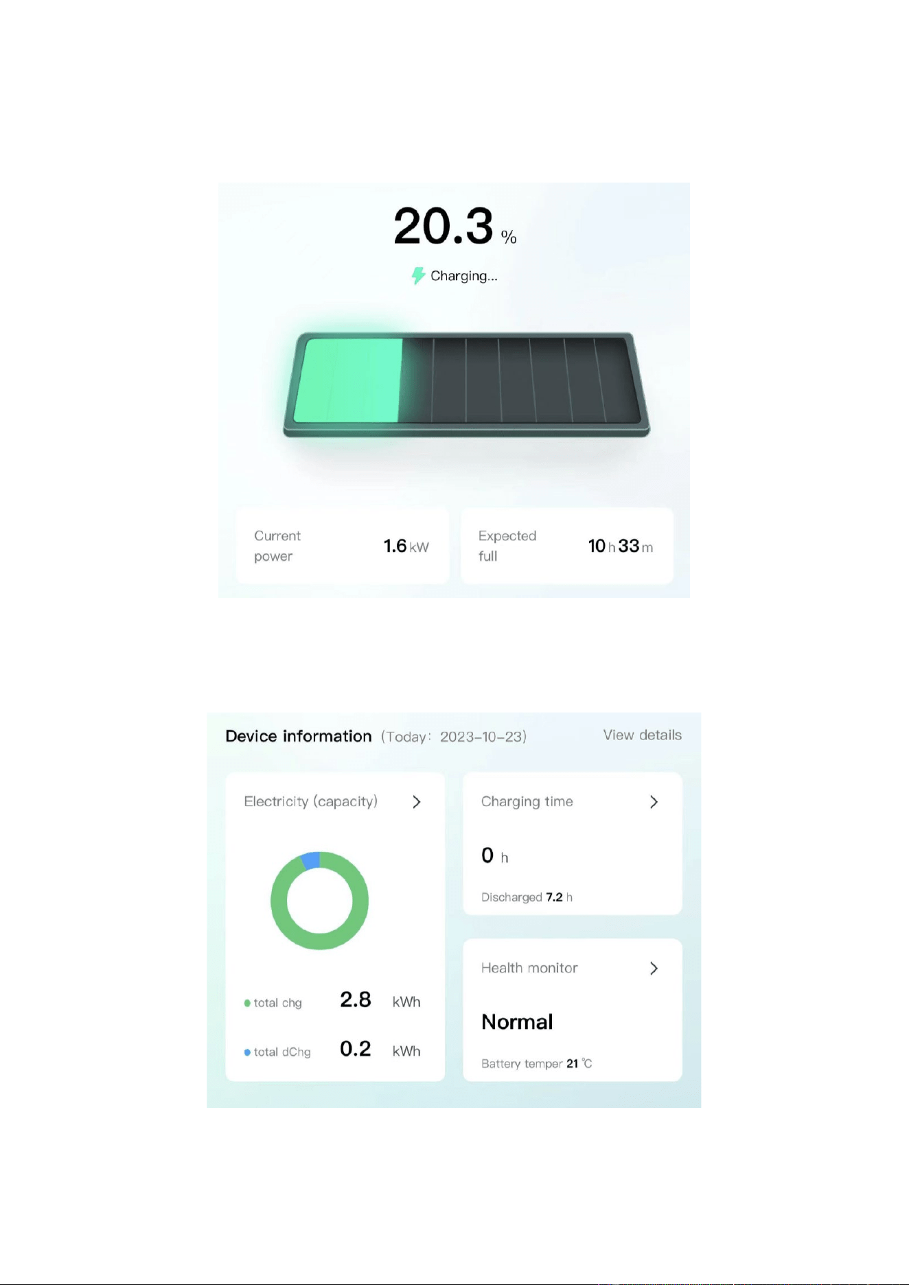
• Middle area: Displays the current battery charging and discharging status, battery
percentage, current power, and estimated full time.
•
The bottom area: Displays the device battery, charging time, and health check
overview data of the day in the form of a card. You can click the corresponding card to
view the details.
45
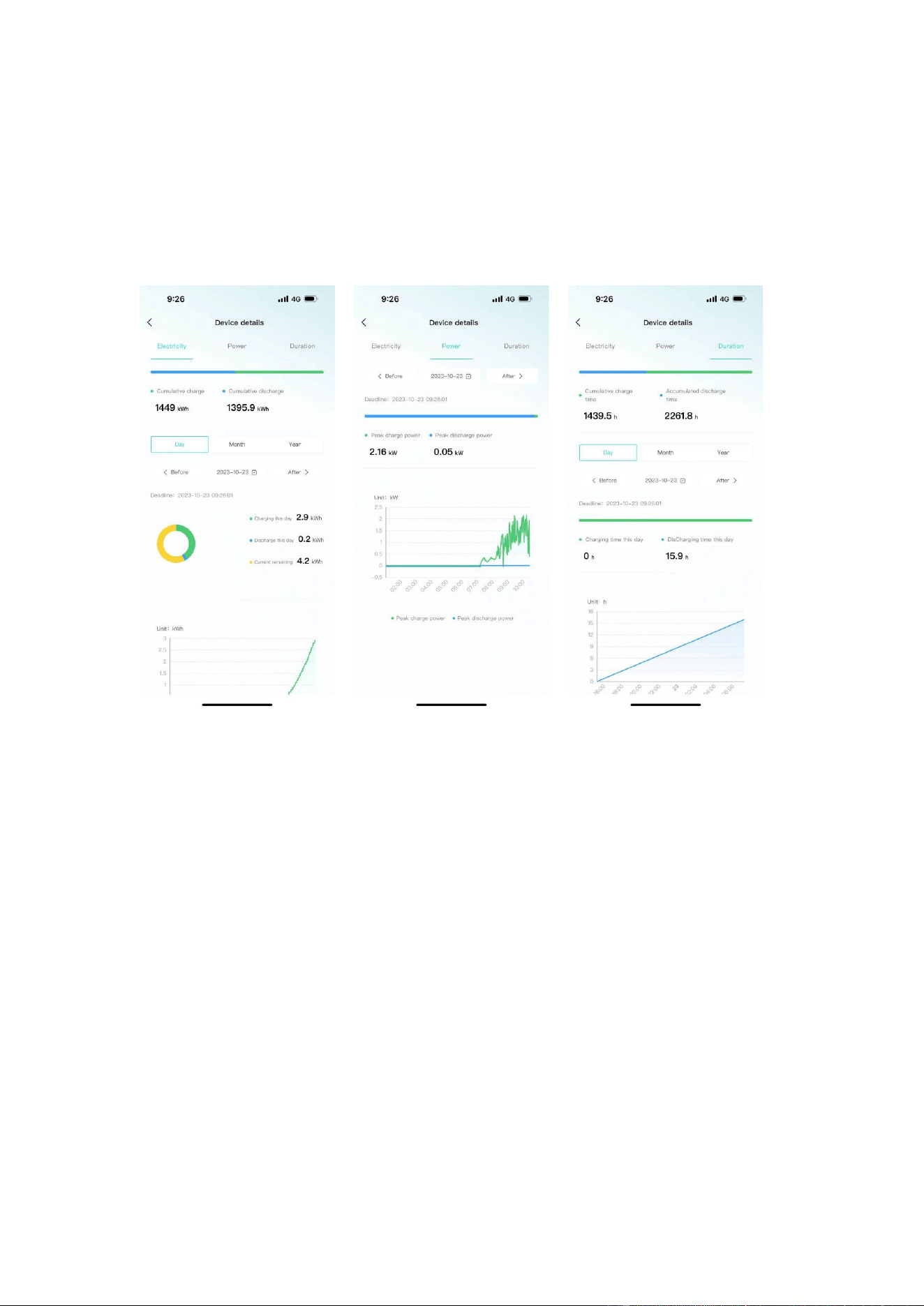
6.4.2 Data details
Display the data details of the current device, and view the battery, charging and
discharging power, and charging and discharging time data separately, and support
time filtering.
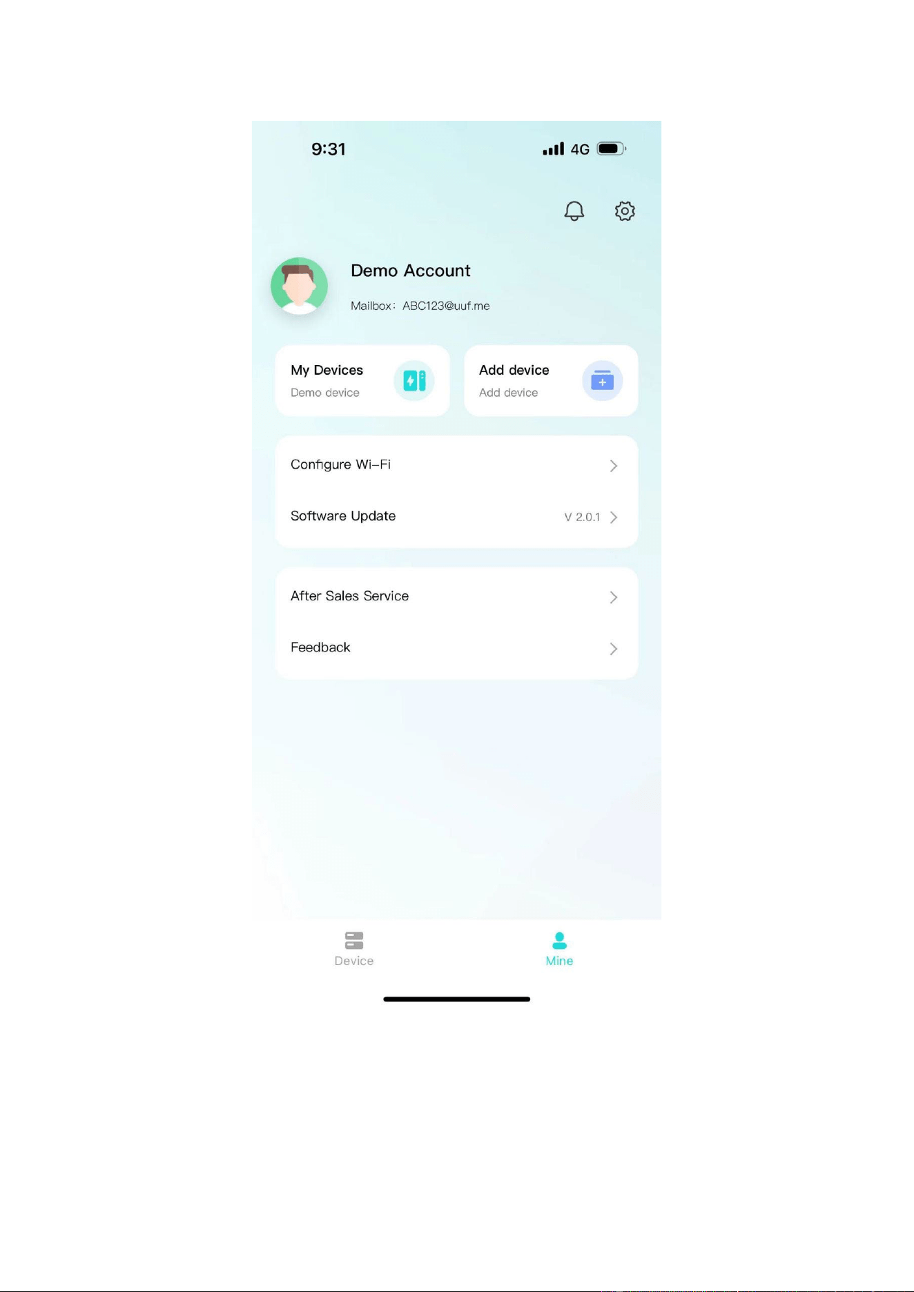
6.4.3 Mine
My page allows users to view my devices, add devices, configure WiFi, software
updates, after-sales services, problem feedback, app settings .
46
•
Click "My Devices" to enter Facility Management. You can view all devices
managed under the current account, switch devices displayed on the homepage,
unbind devices, and other operations.
47

•
Click "Add Device" to enter the code scanning page.
•
Click "Equipment Distribution Network" to enter the equipment distribution
48
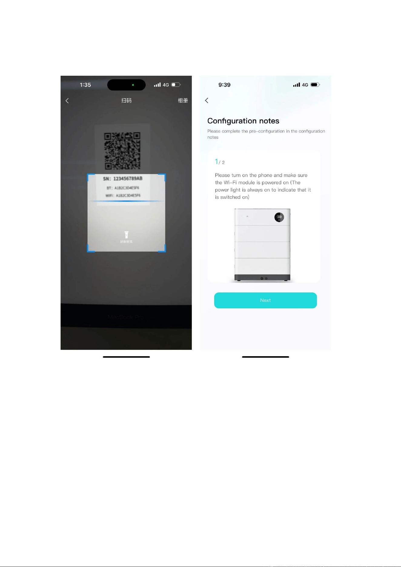
network process.
•
After clicking "software update", it will enter the version detection. If there is a new
version, it will be updated.
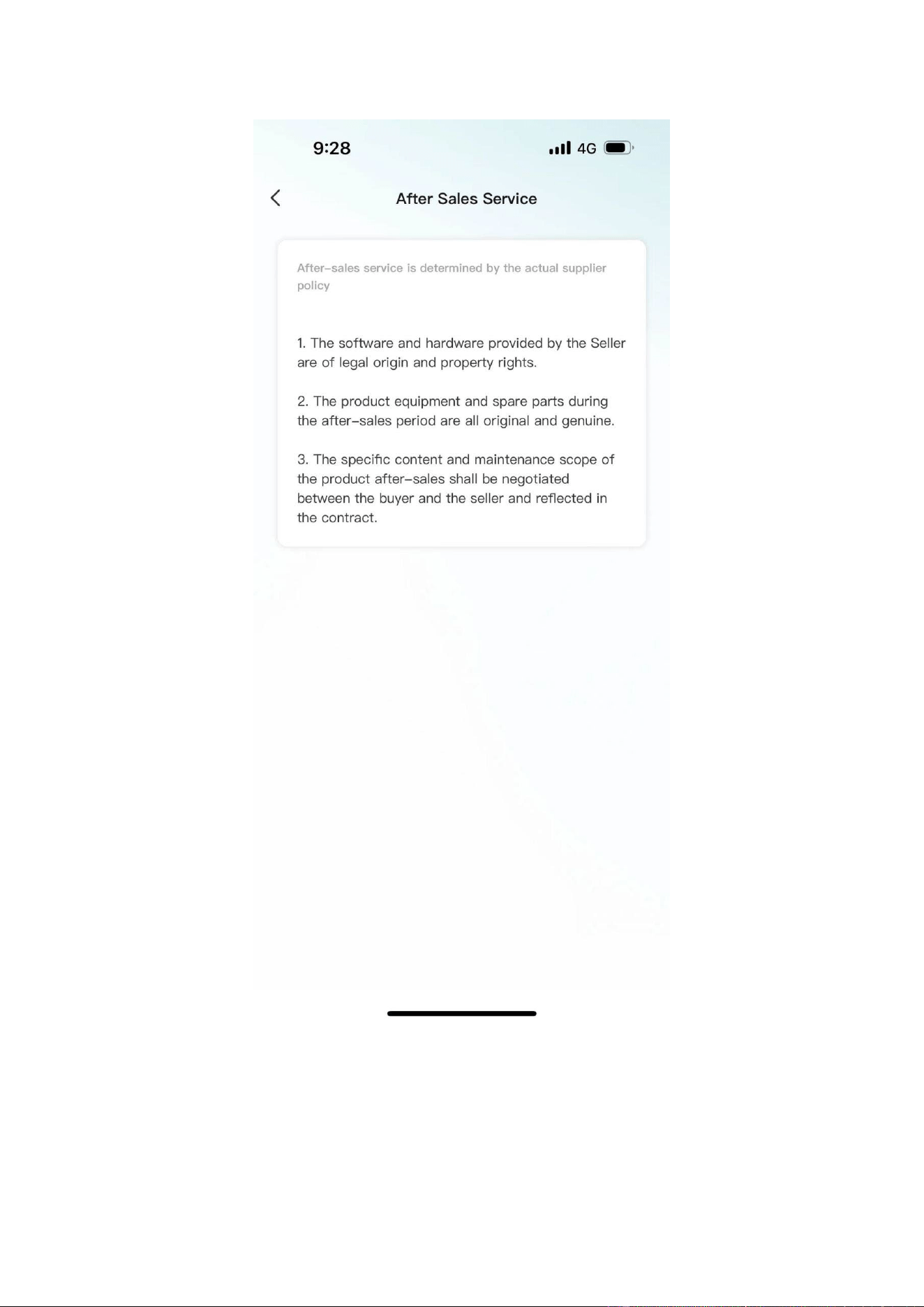
•
Click "after-sales services" and enter the after-sales services page to display the
after-sales services declaration of the current supplier.
49
•
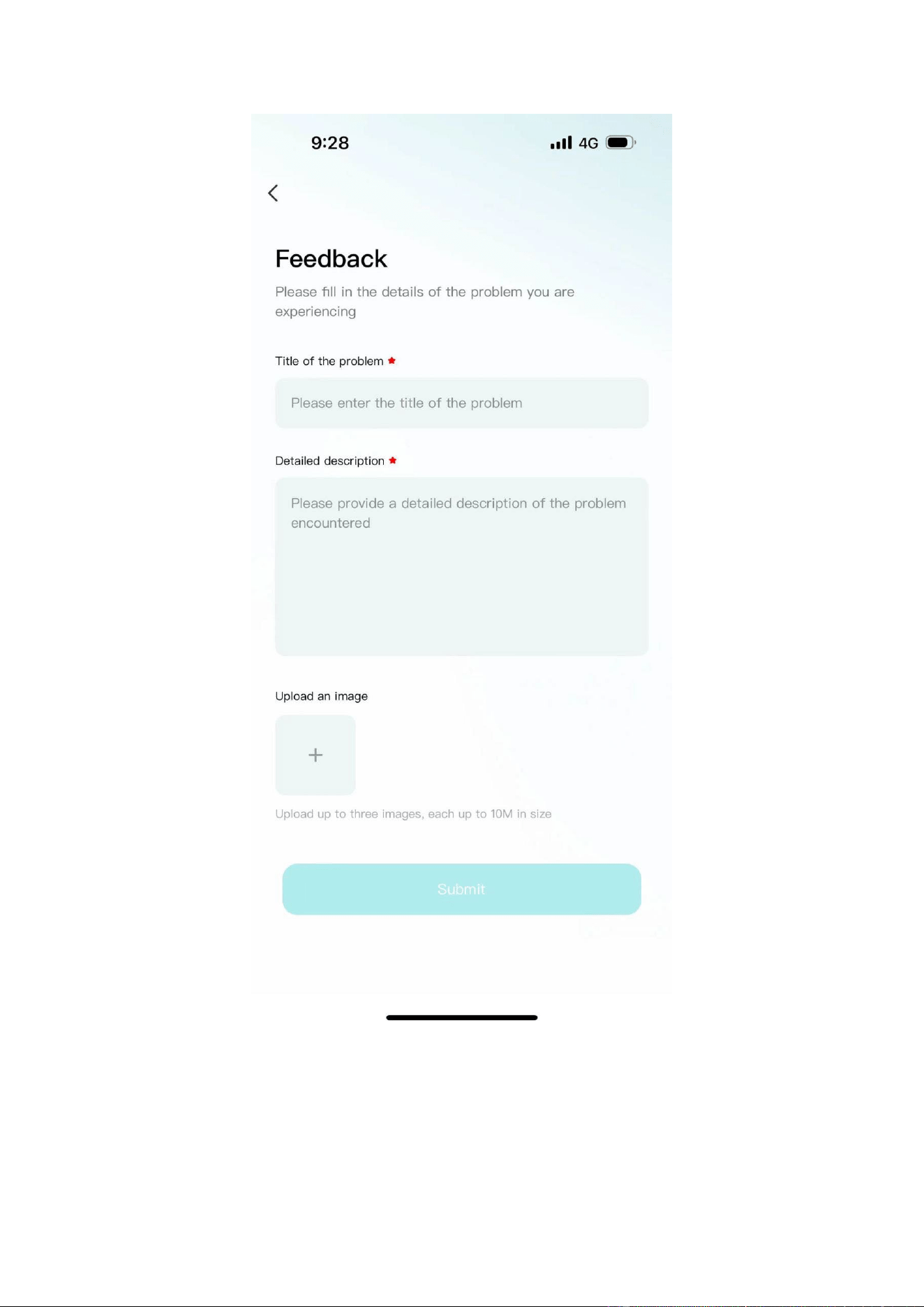
Click "Feedback" to enter the feedback page. You can enter the current problem
that needs feedback and submit it.
50
6.4.4 Message
Click on the device or my page, the message icon above, you can enter the inbox
51
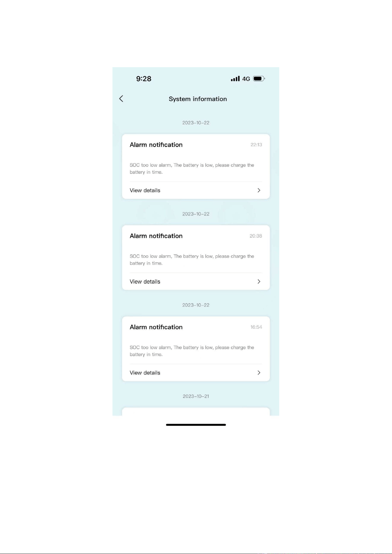
page to view the current notification or chat history.
6.4.5 App settings
•
Click My Pages - Settings icon in the upper-right corner to enter the App Settings
page.
52
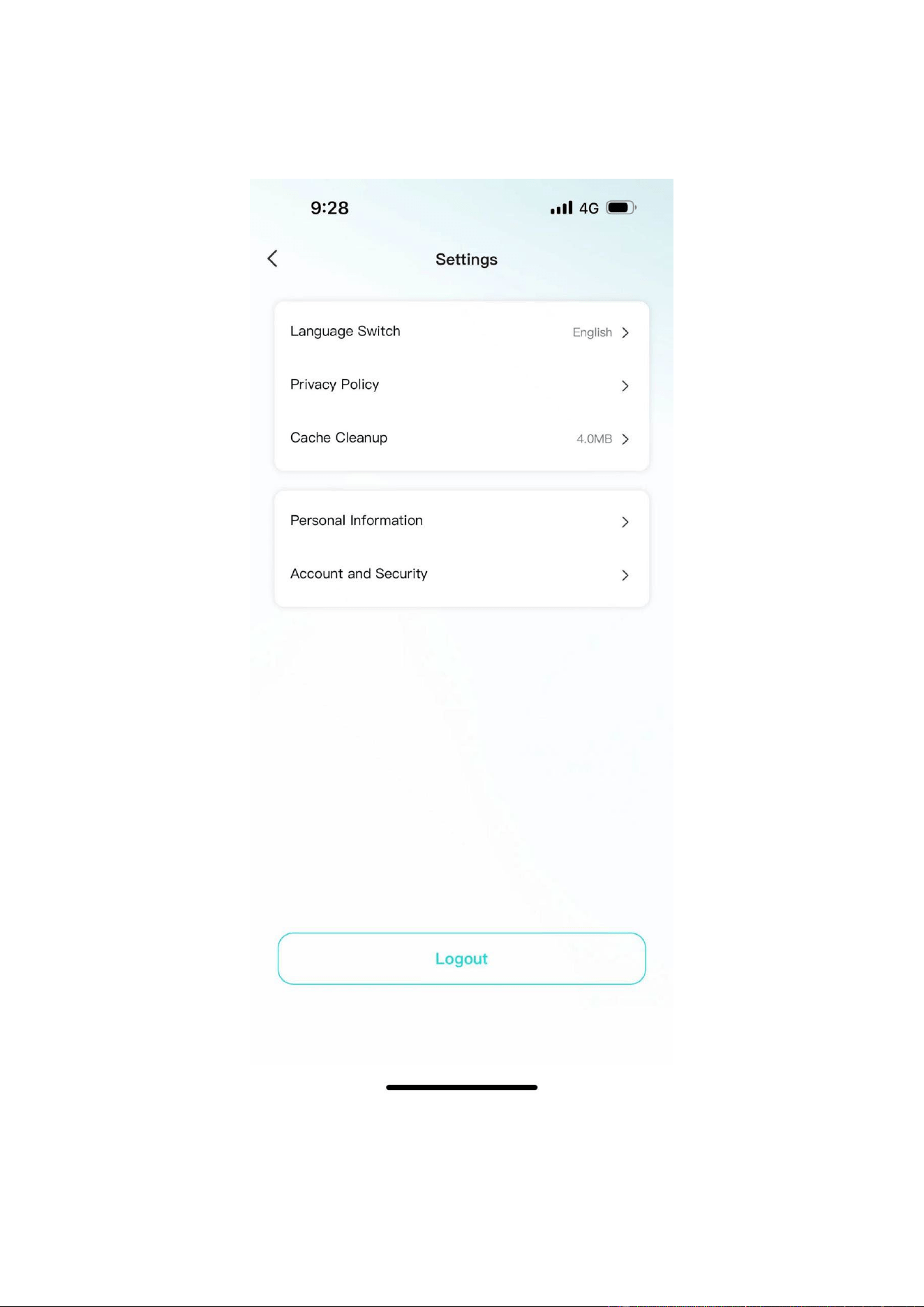
• Settings page support: language switching, Privacy Policy, cache cleaning,
personal information, account and security.
53

7 Maintenance
Warning! Improper decommissioning may cause damage to the equipment and/or
battery inverter.
Before maintenance, ensure that OHR-100 is decommissioned according to relevant provisions.
Note: All maintenance work shall comply with local applicable regulations and standards.
To ensure safe operation, all plug connections must be checked. If necessary, relevant
operators shall press them back into place at least once a year.
which can be used as an auxiliary
The USB-CAN port has the functions of upgrading firmware and recording battery data,
tool.
The following inspection or maintenance must be carried out once a year:
• General visual inspection
• Check all tightened electrical connections. Check the tightening torque according to
the values in the following table. Loose connections must be retightened to the
specified torque.
Connection mode Tightening torque
high-voltage BMS box grounding 4.5Nm
Fixing the lug of the high-voltage BMS box 1.2Nm
Fixing the lug of the battery module 1.2Nm
• Using the monitoring software, check whether the SoC, SoH, battery voltage and
temperature of the battery module are abnormal.
• Shut down and restart OHR-100 once a year.
Note: If the system is installed in a polluted environment, maintenance and cleaning
must be carried out at short intervals.
Note: Clean the battery rack with a dry-cleaning cloth. Ensure that no moisture comes
into contact with the battery connections. Do not use solvents.
54
WICHTIGE HINWEISE
o Dieses Produkt enthält den Batterietyp "Sekundär" (wiederaufladbar).
o Elektro- und Elektronikgeräte, die zu Abfall geworden sind, werden als Altgeräte bezeichnet. Altgeräte dürfen nicht mit anderem
Hausmüll entsorgt werden.
o Besitzer von Altgeräten am Ende der Nutzungsdauer müssen das Gerät bei den von den öffentlichen Entsorgungsträgern oder
Händlern eingerichteten Sammelstellen zurückgeben. Diese Rücksendung ist für Sie mit keinen Kosten verbunden.
o Besitzer von Altgeräten sind verpflichtet, zugängliche Batterien / Akkus sowie zerstörungsfrei entnehmbare Lampen vor der
Rückgabe aus dem Altgerät zu entfernen. Dies gilt nicht, wenn Altgeräte unter Beteiligung einer öffentlich-rechtlichen
Anwaltskanzlei zur Wiederverwendung aufbereitet werden.
o Warnung zum Entfernen des Akkus: Der in diesem Produkt enthaltene Akku darf nur von Fachpersonal entfernt werden. Die
Batterie darf niemals vom Endbenutzer entfernt werden, wenn sie nicht richtig entfernt wird, kann dies die Batterie beschädigen
und einen Brand verursachen.
o Batterien, die aus einem alten elektronischen Gerät entnommen wurden, sollten separat entsorgt werden. Diese
Batterierückgabe verursacht für Sie keine Kosten und der Nutzer ist zur Rückgabe der Batterie verpflichtet.
o Bitte stellen Sie sicher, dass dieses Produkt beim Entfernen des Akkus nicht eingeschaltet ist. Brandgefahr! Vermeiden Sie ein
Kurzschließen der Kontakte einer abgenommenen Batterie. Verbrennen Sie die Batterie nicht. Bitte behandeln Sie den Akku mit
Vorsicht!
o Bei der Entsorgung von Elektrogeräten oder Batterien auf Deponien oder Halden können Schadstoffe ins Grundwasser gelangen
und in die Nahrungskette gelangen und Ihre Gesundheit und Ihr Wohlbefinden schädigen.
o Das Symbol „Gekreuzte Mülltonnen“ weist darauf hin, dass dieses Produkt nicht mit dem anderen Hausmüll entsorgt werden
darf und am Ende seiner Lebensdauer vom unsortierten Hausmüll getrennt gesammelt werden muss.
o Unter folgendem Link gelangen Sie zum Online-Verzeichnis der Sammel- und Rückgabestellen:
https://www.ear-system.de/ear-verzeichnis/sammel-und-ruecknahmestellen
Attention:
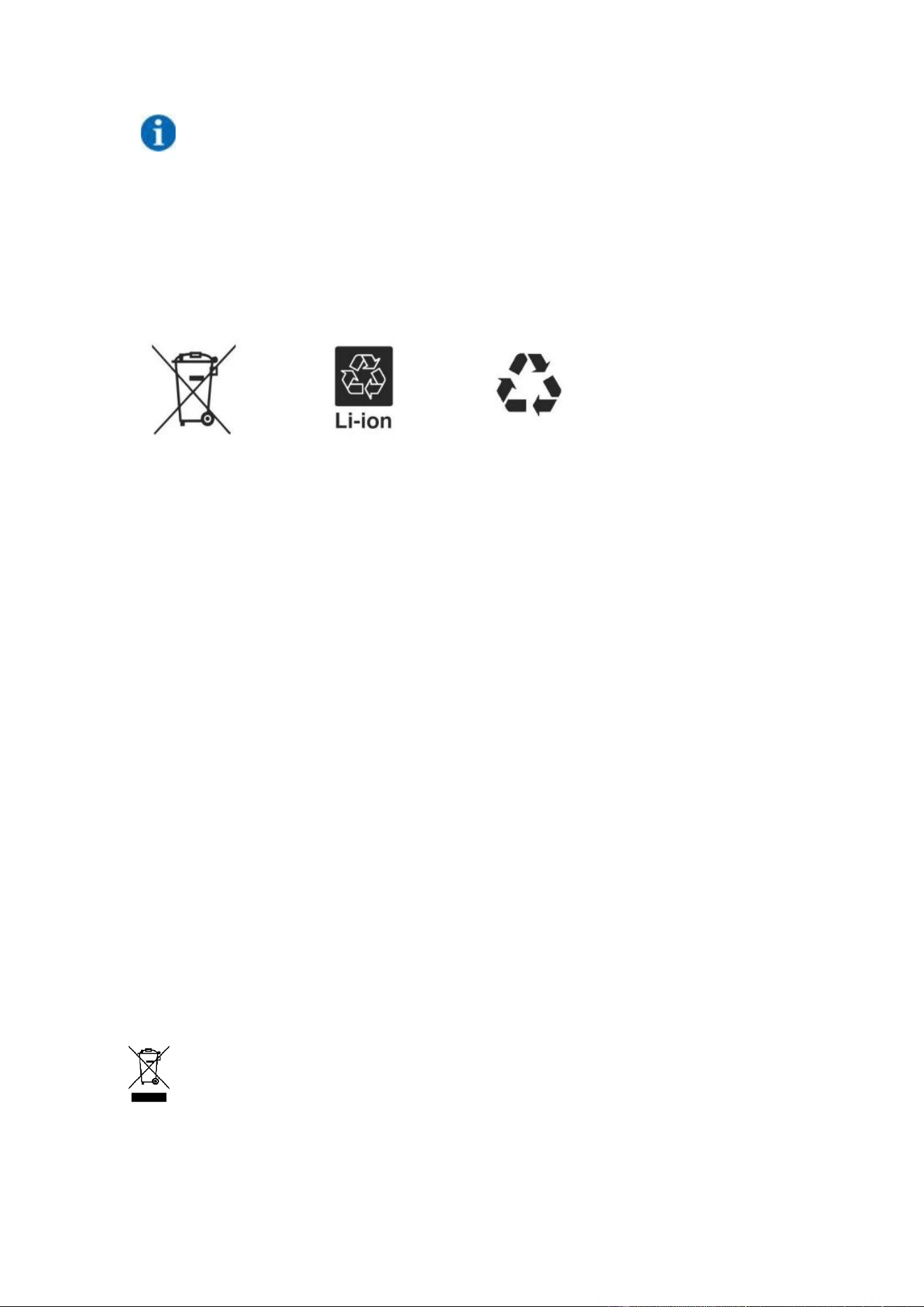
1. Do not dispose of batteries and rechargeable batteries as domestic waste! You are
legally obliged to return used batteries and rechargeable batteries.
2. Waste batteries may contain pollutants that can damage the environment or your health if improperly
stored or handled.
3. Batteries also contain iron, lithium and other important raw materials, which can be recycled.
Do not dispose of batteries as household waste!
Legal Statement
The information contained in the document is the property of V-TAC Europe Ltd.
All information shall not be published in whole or in part without the written permission of V-TAC
Europe Ltd.
55