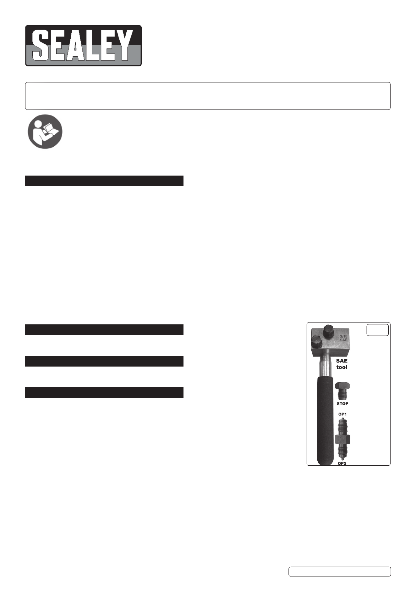
ON-VEHICLE MICRO BRAKE PIPE FLARING
TOOL 3/16” SAE
MODEL NO: PFT12
Thank you for purchasing a Sealey product. Manufactured to a high standard, this product will, if used according to these instructions,
and properly maintained, give you years of trouble free performance.
IMPORTANT: PLEASE READ THESE INSTRUCTIONS CAREFULLY. NOTE THE SAFE OPERATIONAL REQUIREMENTS, WARNINGS & CAUTIONS. USE
THE PRODUCT CORRECTLY AND WITH CARE FOR THE PURPOSE FOR WHICH IT IS INTENDED. FAILURE TO DO SO MAY CAUSE DAMAGE AND/OR
PERSONAL INJURY AND WILL INVALIDATE THE WARRANTY. KEEP THESE INSTRUCTIONS SAFE FOR FUTURE USE.
1. SAFETY
WARNING! Ensure Health & Safety, local authority and general workshop practice requirements are adhered to when using this
equipment. Familiarise yourself with the application and limitations, as well as the potential hazards of the set.
9 This set is suitable for steel pipe.
Maintain the set in good condition.
9 Replace or repair damaged parts. Use genuine parts only. Unauthorised parts may be dangerous and will invalidate the warranty.
9 Locate the aring set in a suitable work area, keep the area clean and tidy and ensure there is adequate lighting.
WARNING! Always wear approved eye or face protection when using the aring tools.
9 Keep children and unauthorised persons away from the working area.
8 DO NOT use the set for any purpose other than for which it is designed.
8 DO NOT use the set if any parts are damaged or missing as this may cause failure and/or personal injury.
8 DO NOT allow untrained persons to use the set.
8 DO NOT attempt to are piping when you are tired, under the inuence of alcohol, drugs or intoxicating medication.
9 When not in use clean set components, replace in case and store in a safe, dry, childproof area.
WARNING! The safe operation of a vehicle, or other equipment, may well depend on the quality of the are produced. Discard any are
which is mis-formed.
WARNING! The warnings, cautions and instructions discussed in this manual cannot cover all possible conditions and situations that
may occur. It must be understood that common sense and caution are factors which cannot be built into this product, but must be
applied by the operator.
2. INTRODUCTION
Produces accurate automotive SAE flares on 3/16” pipes. Lightweight body makes it ideal for splicing in
replacement sections of brake pipe on-vehicle. Suitable for copper, cupro-nickel and steel pipes.
3. SPECIFICATION
Model No: ............................................................ PFT12
Contents: ........................................................3/16” SAE
4. OPERATION
WARNING! Ensure you are familiar with the various types of are before using this equipment.
WARNING! Before using the aring kit, ensure that you have read and understood the ‘Safety
Instructions’ in Section 1.
4.1. PREPARATION OF THE BRAKE PIPE
4.1.1. The end of the pipe must be cut square.
4.1.2. The outside edge of the pipe must be chamfered to approximately 0.25mm x 45º.
IMPORTANT: If the pipe is plastic covered, this must be cut back for 6mm from the end of the pipe to
be ared. Ensure the pipe is not scored or any metal removed during this operation. DO NOT use an
abrasive cloth.
IMPORTANT: If the pipe is painted it is recommended that the paint be removed for the length of the
die by a chemical paint remover, not an abrasive cloth. Observe all manufacturers’ precautions when using chemical paint remover.
Finally remove any grease present. These two operations will improve the die jaw grip whilst aring.
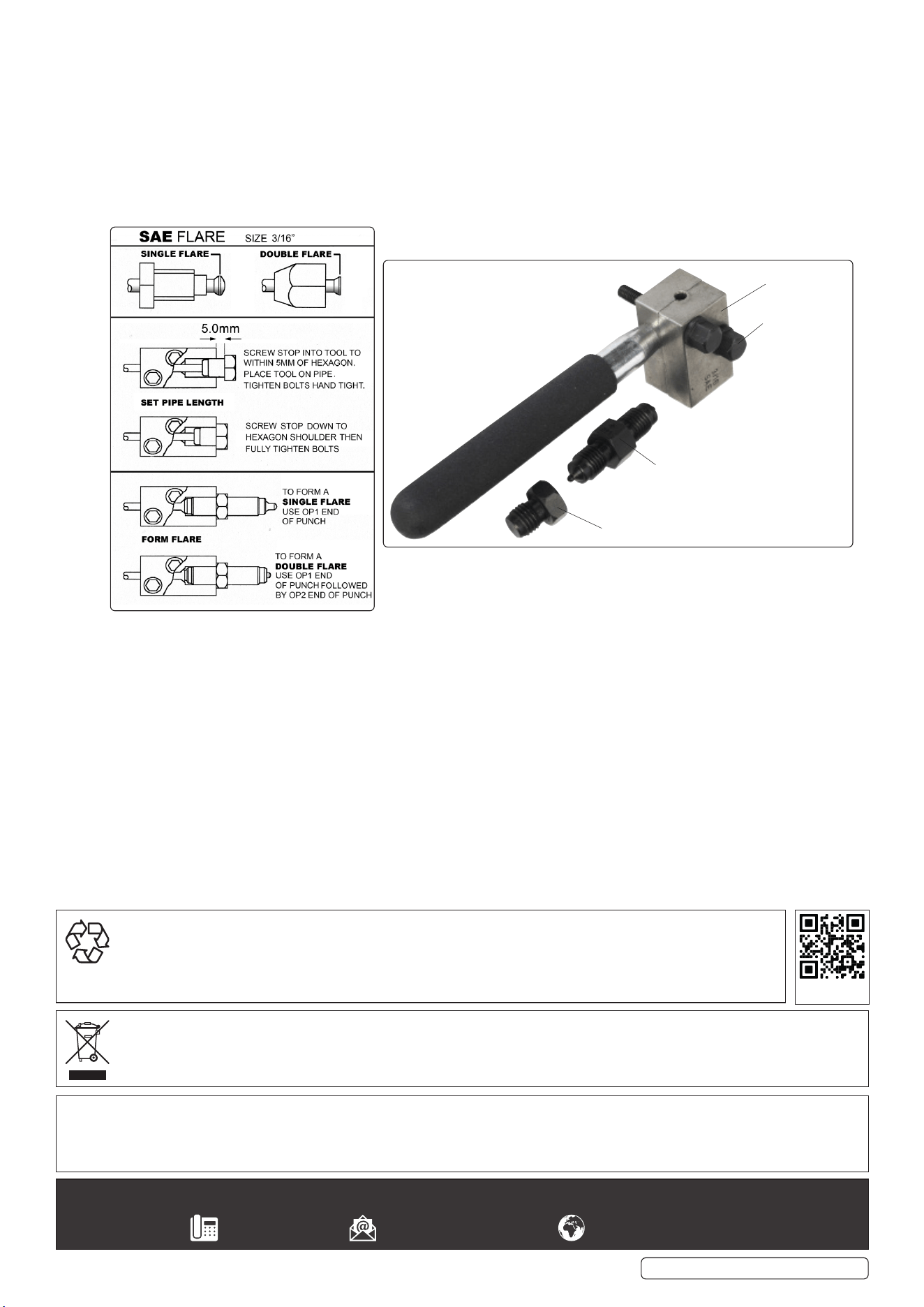
4.2. CREATION OF 3/16” SAE SINGLE FLARE
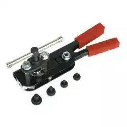
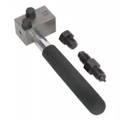
4.2.1. Use the SAE tool, stop and double ended punch as shown in fig.1.
4.2.2. The stop must be screwed into the tool to within 5mm of the hexagon.
4.2.3. Slide the tool onto pipe.
4.2.4. Tighten the locking screws by hand, just enough to grip the pipe.
IMPORTANT: DO NOT over tighten at this stage or the stop will damage the pipe.
4.2.5. Screw the stop into the tool until fully tightened. (A 16mm ratchet spanner is recommended, but not included.)
4.2.6. Tighten the locking screws fully to clamp the pipe. (A 10mm ratchet spanner is recommended, but not included.)
IMPORTANT: If the locking screws are not tight enough then the pipe will push back during the flare process and will not
produce the correct flare.
Refer to
instruction
manual
g.1
PFT12 Issue 2 (ALL) 04/07/23
Original Language Version
© Jack Sealey Limited
PFT12 Issue 2 (ALL) 04/07/23
Original Language Version
© Jack Sealey Limited
Sealey Group, Kempson Way, Suffolk Business Park, Bury St Edmunds, Suffolk. IP32 7AR
01284 757500 sales@sealey.co.uk www.sealey.co.uk
ENVIRONMENT PROTECTION
Recycle unwanted materials instead of disposing of them as waste. All tools, accessories and packaging should be
sorted, taken to a recycling centre and disposed of in a manner which is compatible with the environment. When
the product becomes completely unserviceable and requires disposal, drain any uids (if applicable) into approved
containers and dispose of the product and uids according to local regulations.
WEEE REGULATIONS
Dispose of this product at the end of its working life in compliance with the EU Directive on Waste Electrical and Electronic
Equipment (WEEE). When the product is no longer required, it must be disposed of in an environmentally protective way. Contact
your local solid waste authority for recycling information.
Note: It is our policy to continually improve products and as such we reserve the right to alter data, specications and component parts
without prior notice.
Important: No Liability is accepted for incorrect use of this product.
Warranty: Guarantee is 12 months from purchase date, proof of which is required for any claim.
REGISTER YOUR
PURCHASE HERE
4.2.7. Undo and remove the stop.
4.2.8. Insert the OP1 end punch and tighten fully up to the hexagon in order to form the flare.
4.2.9. Unscrew the punch. The single flare is now complete.
4.2.10. Undo the locking screws and remove the tool from the pipe.
4.3. CREATION OF 3/16” SAE DOUBLE FLARE
4.3.1. Firstly follow steps 4.2.1 to 4.2.10. to form a single are.
4.3.2. Reverse the punch and insert the OP2 end into the tool and fully tighten up to the hexagon in order to form the are.
4.3.3. Unscrew the punch.
4.3.4. Undo the locking screws and remove the tool from the pipe. The double are is now complete.
Note: A spot of grease on the end of the punch helps the are process.
DIE JAWS
LOCKING SCREWS
PUNCH
STOP