
www.cmadishmachines.com
TABLE OF CONTENTS
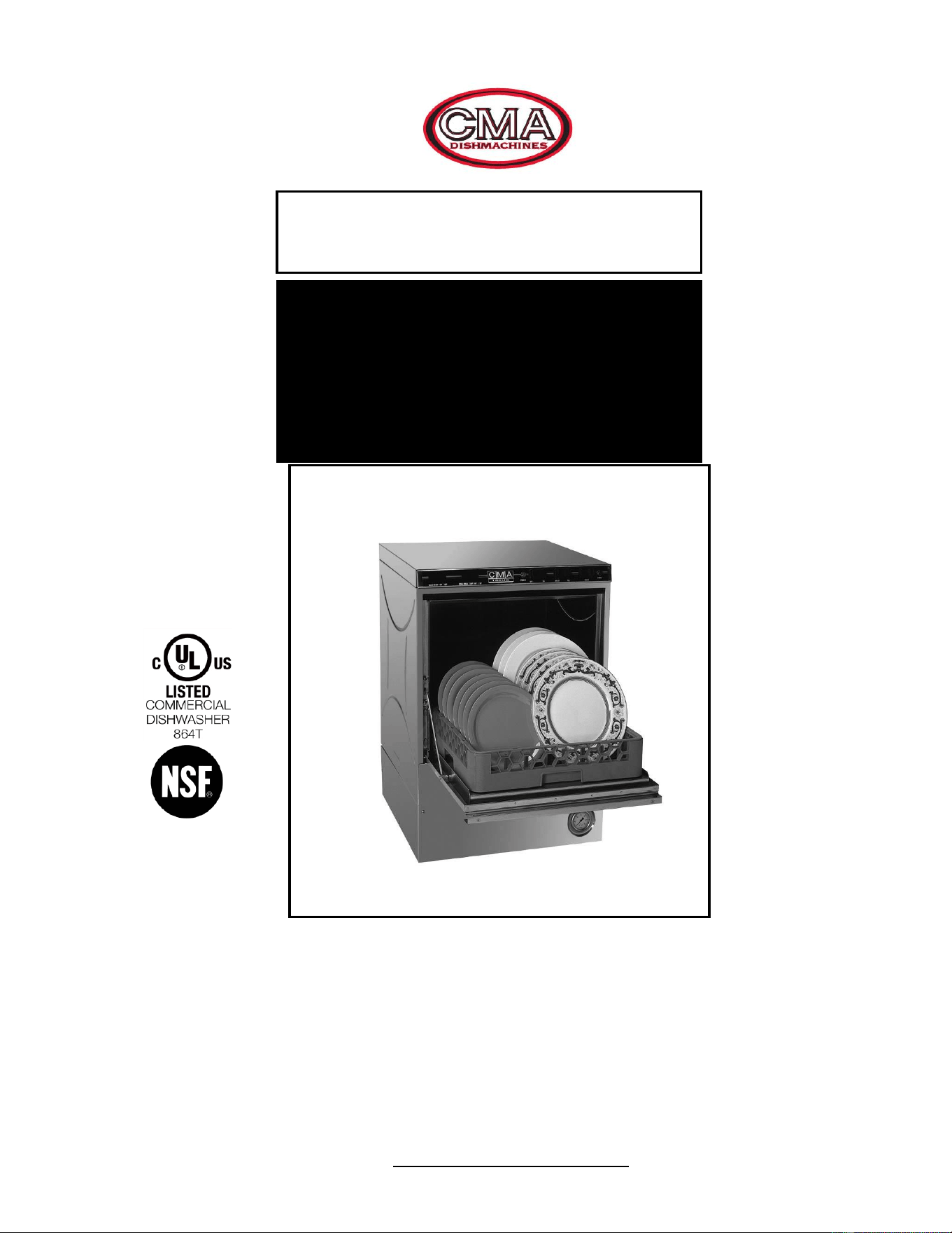
MODEL CMA-180UC
1. SPECIFICATIONS .................................................................................. 2
1.1. CMA-180UC ......................................................................................................................... 2
1.2. CMA-180UC OPERATIONAL CYCLE ...................................................................................... 3
2. GETTING STARTED ............................................................................... 5
2.1. INTRODUCTION TO CMA-180UC ........................................................................................... 5
2.2. RECEIVING AND INSTALLATION.............................................................................................. 6
2.2.1. Electrical ....................................................................................................................... 6
2.2.2. Plumbing ........................................................................................................................ 6
2.2.3. Detergent And Rinse Chemical Dispenser (Optional).. ................................................. 7
2.2.4. External Detergent and Rinse Dispenser (Optional). ................................................... 8
2.2.5. Safe-T-Temp Feature ...................................................................................................10
2.2.6. Drain Water Tempering Kit .........................................................................................11
2.2.7. Booster Heater Setup ....................................................................................................12
2.2.8. Installers Checklist .......................................................................................................12
3. OPERATION ......................................................................................... 13
3.1. INITIAL SETUP .......................................................................................................................13
3.1.1. Rinse Pressure Regulator (Models manufactured prior to January 2008 and starting
April 2018)....................................................................................................................................13
3.1.2. Flow Disc (Models manufactured between January 2008 and April 2018). ................13
3.1.3. Rinse and Wash Temperatures .....................................................................................13
3.1.4. Post Instructions ...........................................................................................................13
3.2. STARTUP PROCEDURES ..........................................................................................................13
3.3. OPERATING AND CLEANING INSTRUCTIONS ...............................................................,15 & 16
3.4. PREVENTIVE MAINTENANCE CHART .....................................................................................17
3.5. QUICK SERVICE GUIDE ...........................................................................................................18
3.6. TROUBLESHOOTING ...............................................................................................................19
4. PARTS KIT ........................................................................................... 22
4.1. INITIAL PARTS KIT (P/N 1100.66) .........................................................................................22
4.2. DRAIN PUMP .........................................................................................................................23
4.3. DRAIN PUMP REMOVAL INSTRUCTIONS ................................................................................24
5. CUSTOMER NOTICE ........................................................................... 25
6. ELECTRICAL DIAGRAMS ................................................................... 26
Specifications
MODEL CMA-180UC INSTALLATION & OPERATION MANUAL Rev. 1.20 Page
2
1. Specifications
1.1. CMA-180UC
WATER CONSUMPTION
PER RACK
.75 GAL.
(2.83 L)
PER HOUR
17.9 GAL.
(67.6 L)
OPERATING CYCLE
WASH TIME-SEC
94
94
RINSE TIME-SEC
16
16
DWELL TIME-SEC
10
10
TOTAL CYCLE
2 MIN.
2 MIN.
OPERATING CAPACITY
RACKS PER HOUR
30
30
WASH TANK CAPACITY
2.5 GAL.
(9.46 L)
PUMP CAPACITY
38 GPM
(144 LPM)
120°F (49°C)
140°F
(60°C)
½”
1.27cm
1”
2.54cm
WATER REQUIREMENTS
REQUIRED MINIMUM TEMP.
RECOMMENDED TEMP.
WATER INLET
DRAIN CONNECTION
RINSE PRESSURE SET
20 PSI5 PSI
1.41 kg/cm
2
150°F -160°F
(65.5°C/71°C)
CYCLE TEMPERATURES
WASH-°F
RINSE-°F
180°F -195°F
(82°C/90°C)
FRAME DIMENSIONS
DEPTH
25”
(63.5 cm)
WIDTH
24”
(60.96 cm)
HEIGHT
33 ¼”
(84.45 cm)
MAX CLEARANCE FOR DISHES
14.5”
(36.8 cm)
ELECTRICAL RATING*
208 VOLTS
1 PH—60 Hz
230 VOLTS
1 PH—60 Hz
33 AMPS
35 AMPS
BOOSTER HEATER
5.3 kW
6.5 kW
WASH PUMP MOTOR
1 HP
1 HP
THIS SYSTEM REQUIRES THREE POWER WIRES, WHICH INCLUDES A CURRENT
CARRYING NEUTRAL. AN ADDITIONAL FOURTH WIRE MUST BE PROVIDED FOR MACHINE
GROUND. GFCI BREAKER IF REQUIRED IS OK. HARDWIRE ONLY, NO OUTLET.
SHIPPING WEIGHT
234#
(106 kg)
METRIC
EQUIVALENT
Note: The required water pressure to the dishwasher is 15-65 PSI. If pressure is lower than 15 psi,
improper machine operation may result.
Specifications
MODEL CMA-180UC INSTALLATION & OPERATION MANUAL Rev. 1.20 Page
3
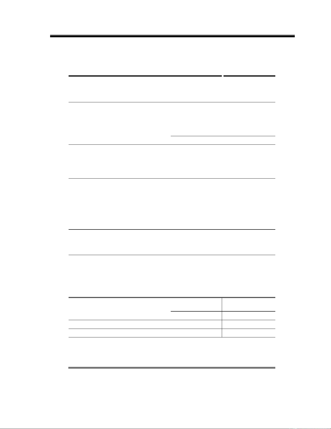
1.2. CMA-180UC Operational Cycle
The CMA-180UC Operational Cycle has a total cycle time of 2 minutes (120 seconds). The
Timing Diagram and the steps listed below detail the individual functions that are executed
during each Operational Cycle.
1. With the machine powered up toggling the START switch begins a cycle.
a) Toggling the START switch energizes both the Cam Timer motor and the Instant Start
Relay. The Instant Start Relay latches ON the power to the Cam Timer motor so that
the START switch can be released a moment after it has been toggled without the Cam
Timer motor losing power.
b) After about 1.5 seconds the Cam Timer’s first cam—the Cam Timer Motor Cam—
latches ON the power to the Cam Timer motor and drops out the Instant Start Relay.
The Cam Timer motor continues to run for a total of 2 minutes, at which time it
switches OFF—resetting the Cam Timer—and waits for the next START command.
2. The Cam Timer’s third cam controls the Wash Pump. The Wash Pump comes ON about 3
seconds into the Operational Cycle and continues to run for 94 seconds. This 94-second
period is the Wash Cycle.
3. At the same time that the Wash Pump comes ON the Cam Timer’s fourth cam powers ON
the Drain Pump—if one is present—and keeps it running for about 7 seconds before
powering OFF. This cam turns ON again midway through the Rinse Cycle and stays ON
for 10 seconds, turning OFF 2 seconds after the Rinse Cycle has completed.
Seconds: 0 10 20 30 40 50 60 70 80 90 100 110 120
Instant
Start Relay
Cam Timer
Motor Cam
Rinse Cycle
Cam
Wash Cycle
Cam
Drain
Pump Cam
Safe-T-
Temp Cam

Specifications
MODEL CMA-180UC INSTALLATION & OPERATION MANUAL Rev. 1.20 Page
4
4. About 3 seconds after the Wash Cycle has completed the Cam Timer’s second cam, which
controls the Rinse Cycle, turns ON—energizing the Water Solenoid—and stays ON for 16
seconds. This 16-second period is the Rinse Cycle.
5. When the cam timer assembly approaches the final rinse portion of the cycle, the “Safe-T-
Temp” fifth micro switch will pause cam timer assembly if the booster heater has not
reached 180 degrees. Machine will remain in wash cycle mode until 180-degree rinse
temperature is reached, and at this time the cam timer will advance automatically into the
rinse cycle and dispense 180 degrees rinse water over the dishes.
6. Cam switches 6 and 7 (not shown) found on machines built after January 2020 control the
detergent and rinse pumps respectively. They turn ON at the beginning of the wash and
rinse cycle respectively and run for a few seconds to provide sufficient detergent and rinse
additive. These cams can be adjusted as necessary for proper chemical dosage. See
section 4.1.1 Cam Adjustment
Note: Use only commercial-grade detergents and rinse additives recommended by your
chemical professional. Do not use detergents and rinse additives formulated for residential
dishwashers.

Getting Started
MODEL CMA-180UC INSTALLATION & OPERATION MANUAL Rev. 1.20 Page
5
2. Getting Started
2.1. Introduction to CMA-180UC
This manual is structured to provide a complete reference guide to the CMA-180UC. It covers
every version produced so some items may not be applicable to your 180UC.
The CMA-180UC is a hot water sanitizing, single rack, under-counter dishmachine. It is a
standalone machine featuring a self-contained booster heater. The only external connections
necessary are power supply, water supply, drainpipe, and optional chemical dispensers for
machines made before 2019. The machine uses re-circulated wash water and fresh water final-
rinse.
Operation of the CMA-180UC is extremely user friendly. To initially fill the machine each day,
push the Power switch to the "ON" position. Press and hold the "Fill" button for 25 seconds.
Machines built prior to January 2020 will automatically fill to the correct level when powered "ON".
The 180UC has one heater located in the booster tank that heats the wash tank too. It will
maintain the wash water temperature at 155°F. The booster heater will produce a minimum of
180°F final rinse water each cycle.
The supply water to the CMA-180UC must be a minimum of 120°F with a 4 GPM (Gallons per
Minute) flow rate. The supply line must be ½” minimum. The plumbing connection is located at
the back of the machine.
The machine retains the features of the standard CMA-180 Series in that it has a scrap tray and
the manner in which the tank is filled ensures that the dishes are always rinsed with fresh water
instead of re-circulated water. The CMA-180UC is the first under-counter dishmachine of its kind
to discharge soil from the wash tank into a scrap tray outside of the wash chamber. This feature
keeps the wash water much cleaner over long periods of time. The scrap tray may be emptied on
a periodic basis without interruption of the flow of work, thereby providing a much cleaner
environment for the wash and rinse cycle.
The first section explains how the machine is packaged and what to look for when receiving the
machine. After unpacking the machine, this manual explains how to install and set up the machine
for use. Requirements are given for plumbing, wiring, and space considerations. These attributes
of the machine are always taken into consideration by our well-trained sales representatives prior
to the order being placed. In the manual, guidance is also given for installation to ensure that the
machine will be able to run at optimum conditions. The Operation Section of the manual may be
used for instruction and procedures when required. We make this portion of the manual easy to
understand so that all levels of operators may be able to read and comprehend the operation of
the machine. The function of the machine itself is mostly automatic and takes little training to put
into full operation. The Operation Section also includes diagnostic considerations for the machine
when problems occur.
DISCLAIMERS
CMA expressly disclaims any and all warranties, express or implied, relating to the installation of any and all CMA equipment that is installed by chemical dealers, contracted servicers or third
party servicers to CMA equipment. If the installation instructions are not followed exactly (to the letter), or, if any person or company conducting the installation of the CMA equipment, revise the
installation procedures or alter the instructions in any manner, the CMA warranty becomes void. If, due to the improper installation of CMA equipment, this equipment ceases to operate properly or
affects other parts of the CMA dishwashing equipment, in that the other parts become defective, the CMA warranty becomes void. CMA will not be liable or responsible or warrant CMA
equipment, due to improper installation of any CMA model dishwasher.
CMA does NOT endorse “Tankless On-Demand” water heaters for use on CMA Dishmachine products. On most applications, the
volume of hot water required for commercial dishmachines exceeds the capacity of these types of heaters.
CMA DOES endorse, and highly recommends, the standard “tank” style water heaters, sized properly to handle each particular
facility with their water heating requirements. A “tank” style water heater stores and supplies a large capacity of preheated water
before providing hot water to the dishmachine. To meet required health codes, there must be a reliable and consistent flow of
adequate hot water supplied to the dishmachine.
Warning: cancer and reproductive harm – www.P65Warnings.ca.gov

Getting Started
MODEL CMA-180UC INSTALLATION & OPERATION MANUAL Rev. 1.20 Page
6
2.2. Receiving and Installation
The dishwasher is shipped from the factory in a corrugated box on a wooden pallet. The
installation guidelines give a systematic procedure for setting up the machine.
Start by removing the packaging material. Unwrap the machine and check for the following
component parts:
The Wash Tank Scrap Screen is shipped inside the wash cavity of the machine. This screen must
be in place during operation. It has been designed to perform two basic functions:
1. Strain water that is circulating through the spray arms and pump assembly.
2. A basket to catch broken glass, or heavy solids that may plug the impeller.
Set the machine in place, and level from side-to-side and front-to-back to prevent door leaks.
Steam generated from normal operation may escape from door. Wood, laminates, veneers, etc.
are unsuitable materials for use in areas exposed to dishwasher steam and detergents. Stainless
steel or other moisture-resistant shields are recommended for surfaces adjacent to sides and
tops of under counter dishwashers.
2.2.1. Electrical
1
Prior to installation make sure the electrical supply is compatible with the specifications on the
machines data plate.
Single-phase 230 volt, 60 Hz hard-wired dedicated circuit should be used to supply electrical
energy to the CMA-180UC dishwasher (see specification sheet page 2). This system requires
three power wires, which include a current carrying neutral. An additional fourth wire must be
provided for ground. Approximately 4-feet of ¾” flexible conduit with power leads (L-1, L-2,
Neutral and Ground) extending out of the conduit are provided for easily connecting the power at
installation. The power connection must be located such that there is sufficient length of the
flexible conduit remaining to permit the machine to be moved for cleaning.
WARNING: Electrical and grounding connections must comply with the applicable portions of the
National Electrical Code and/or other local electrical codes.
Note: For supply connections, use copper wire only rated at 90 degree C minimum.
2.2.2. Plumbing
2
Notice to Plumber: The plumber connecting this machine is responsible for making certain that
the water lines are THOROUGHLY FLUSHED OUT BEFORE connecting to the dishwasher.
The supply water to the CMA-180UC must be a minimum of 120°F with a 4 GPM (Gallons per
Minute) flow rate. The pipe supplying the water must be ½” minimum. The plumbing connection
is located at the back of the machine. The machine is equipped with a connection located at the
lower left-hand corner (facing the back) of the machine. A 120°F minimum water line should
be plumbed to this point (see specification sheet page 2). The water line used must be of
sufficient length and flexibility to permit the machine to be moved for cleaning.
Note: high iron levels in the water supply can cause staining and may require an iron filter. High
chlorine levels in the water supply can cause pitting and may require a chloride removal system.
If an inspection of the dishwasher or booster heater reveals lime buildup after the equipment has
been in service, water treatment is recommended. If water softener is already in place, ensure
there is a sufficient level of salt.
1,2
All electrical and plumbing connections must be made by a qualified person who will comply with
all available Federal, State, and Local Health, Electrical, Plumbing and Safety codes
Getting Started
MODEL CMA-180UC INSTALLATION & OPERATION MANUAL Rev. 1.20 Page
7
Warning: If water pressure exceeds 50 PSI, pressure reducing valve (PRV) is recommended.
The CMA-180UC is supplied with a drain pump for elevated drains. For floor gravity drain
applications the drain pump should not be used and a good commercial grade hose needs to be
connected to the discharge side of the diverter valve (drain valve) and run to the floor drain. If
removing a drain pump, safe-end (insulate electrically) the white and purple wires and secure
them out of the way. If a drain pump is used with a floor drain, the drain hose must rise 12 to 16”
before dropping to the floor drain (to reduce any chance of the pump cavitations).
Caution: CMA recommends utilizing a water softening system to maintain water hardness
measurements of 3.5 gpg (grains per gallon) or less. This will assure maximum results
and optimum operation of the dishmachine.
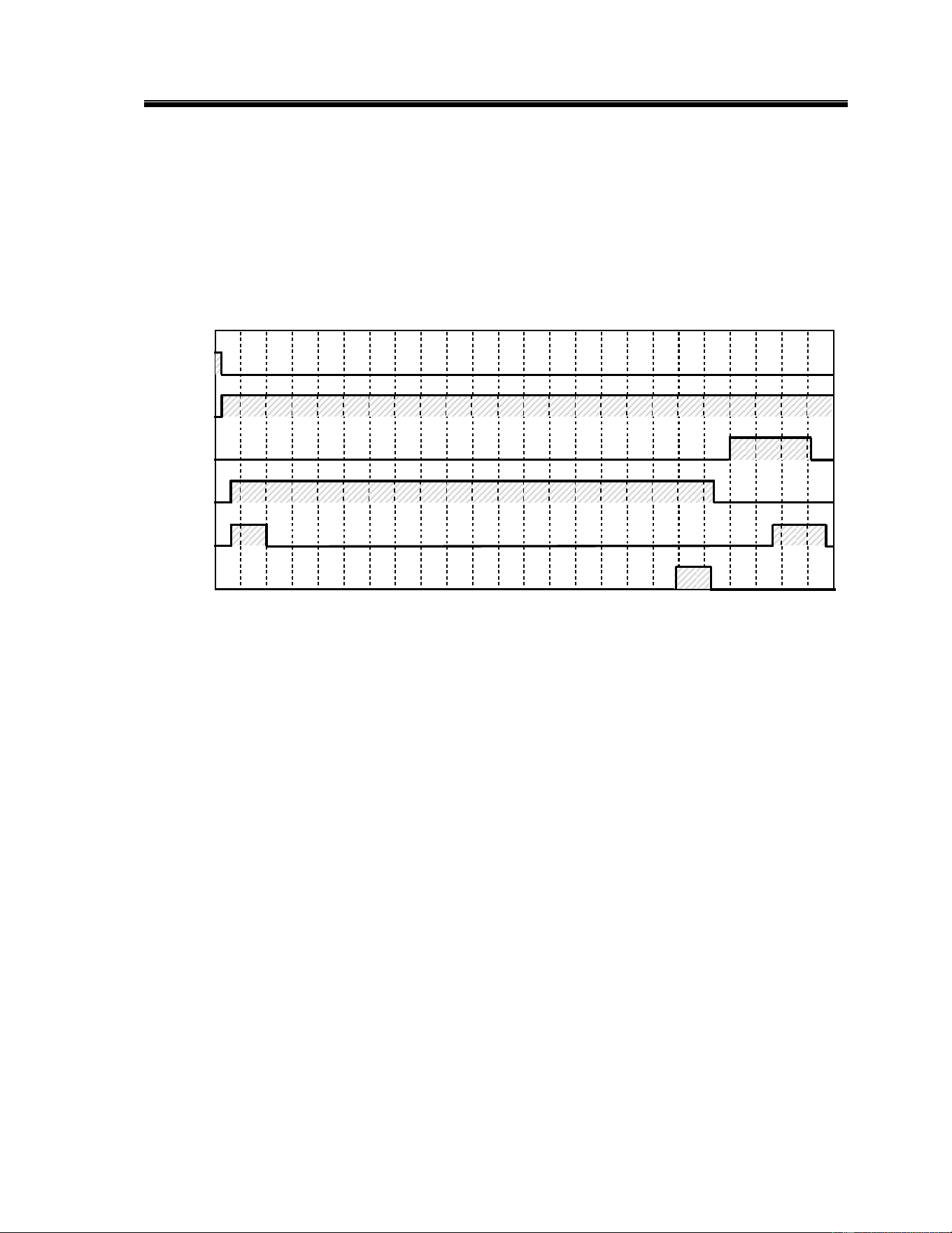
2.2.3. Detergent And Rinse Chemical Dispenser (Prior to January 2020)
Optional built-in chemical dispenser Assembly (CMA P/N 14585.00) has easy access for
chemical settings behind the front kick panel. Both initial charge and recharge is factory pre-set.
Basic settings for both detergent and rinse speed are 50%. Operating fine-adjustment screws on
the dispenser can control the amount of chemicals drawn into chemical lines.
Undercounter machine with the optional dispenser must be ordered separately, as option at time
of order. Optional dispenser has to be pre-wired prior to shipment (see electrical diagram for
wiring options). CMA Dishmachines chemical dispenser for detergent and rinse additive has
been added to all 180UC's built after January 2020.
Note: Use only commercial-grade detergents and rinse aids recommended by your chemical
professional. Do not use detergents and rinse aids formulated for residential dishwashers.
1
All electrical and plumbing connections must be made by a qualified person who will comply with
all available Federal, State, and Local Health, Electrical, Plumbing and Safety codes

Getting Started
MODEL CMA-180UC INSTALLATION & OPERATION MANUAL Rev. 1.20 Page
8
2.2.4. External Detergent and Rinse Dispenser (Optional)
1
.
The NOVA Detergent and Rinse Dispenser has its own reference manual.
Familiarize yourself with the dispenser’s reference manual before proceeding with
installation.
1. The NOVA dispenser is pre-wired with a multi-conductor electrical cable that is to
be run through a conduit to the power block inside the control panel drawer. Use
a ½” watertight conduit meeting all local and national codes. A conduit fitting is
present on the bottom of the dispenser where the power cable exits. A mounting
plate to receive the ½” conduit is provided on the top right-hand corner (facing
the back) of the machine.
i. Run an appropriate length of ½” conduit from your dispenser to the mounting
plate where it will be secured. The conduit needs to be of sufficient length
and flexibility to permit the machine to be moved for cleaning without having
to disconnect any wiring.
ii. Run your dispenser wires through the conduit and through the enclosed area
across the top of the machine and then feed them through the access hole
provided in the back of the control panel drawer.
iii. With the machine’s power “OFF”, connect your detergent and rinse dispenser
wires to the power block supplied and labeled (“DISPENSER 110V - 3 AMPS
MAX”) inside the control panel drawer. The table that follows lists the
function of each conductor of the multi-conductor electrical cable.
Wire Colors
Circuit Voltage
Function
Gray/Violet
90 VAC-130 VAC 50/60 Hz
Main AC Power
Black
90 VAC-130 VAC 50/60 Hz
Main AC Power
Brown
No Connection. Insulate this wire!
This wire is LIVE!
Yellow
90 VAC-130 VAC 50/60 Hz
Detergent Signal
White/Yellow
90 VAC-130 VAC 50/60 Hz
Detergent Signal
Violet
90 VAC -130 VAC 50/60 Hz
Rinse Signal
White/Violet
90 VAC -130 VAC 50/60 Hz
Rinse Signal
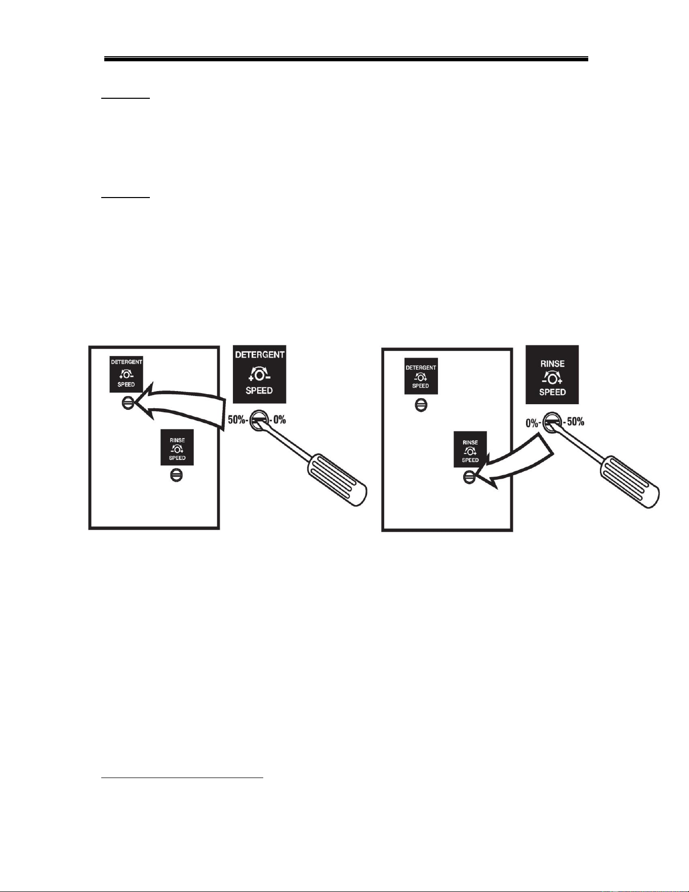
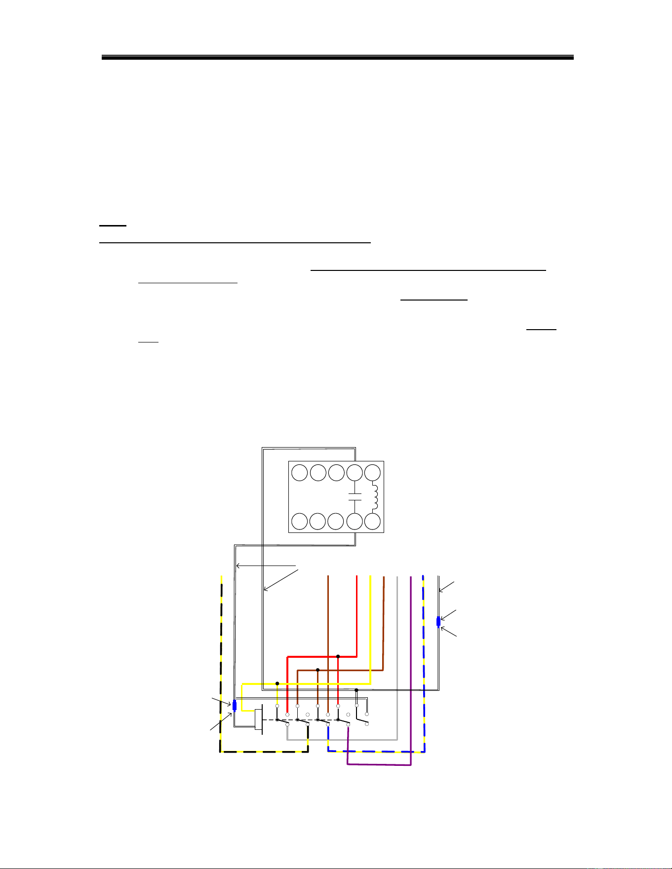
The individual conductors need to be connected as shown in Figure 2.2.4
and as described on next page.
1
All electrical and plumbing connections must be made by a qualified person who will comply with
all available Federal, State, and Local Health, Electrical, Plumbing and Safety codes
Getting Started
MODEL CMA-180UC INSTALLATION & OPERATION MANUAL Rev. 1.20 Page
9
Figure 2.2.4
Note: In Figure 2.2.4 the machine’s wire harness was left out of the back of the
power block to more clearly show the dispenser wires.
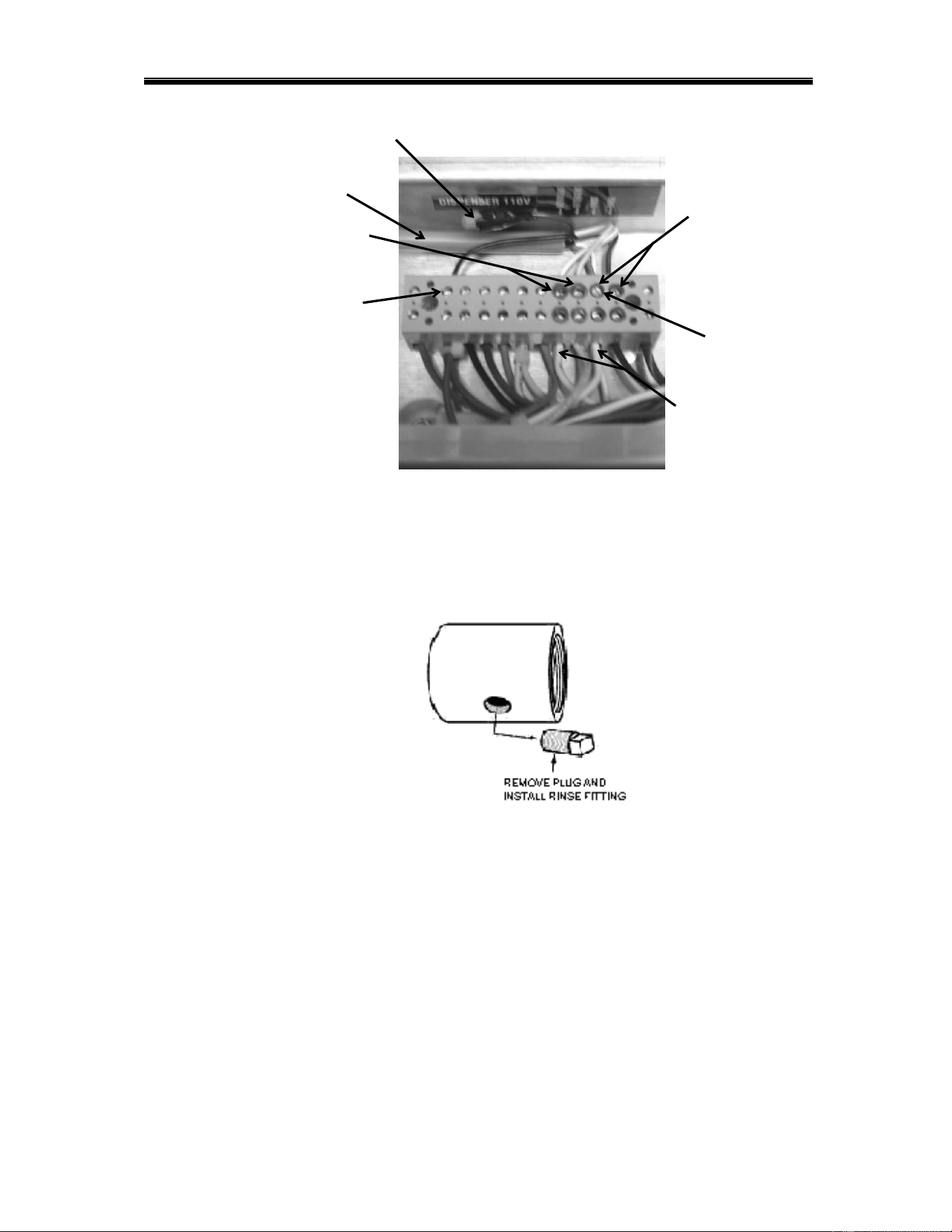
2. Remove the plug from the mixing chamber located by the vacuum breaker on the
back of machine; and install the rinse injection fitting (supplied with your
dispenser). See Figure 2.2.4.
Figure 2.2.4.
3. A 7/8" detergent injection hole is provided in the back of the wash tank. Remove
the S.S. plug and install the detergent fitting (supplied with your dispenser).
4. The final step of installing the CMA supplied Detergent and Rinse Dispenser is
programming it to your specific application. The reference manual supplied with
the dispenser shows you how to program it.
Keep in mind while reading the reference manual that the CMA-180UC
operates in “probe-less” mode. (This mode is selected by setting a value of
“2” in screen 21).
Screen 22 must be set to “1” (Door).
Multi-conductor cable
Black (Main Power)
Note: Machine Neutral
(White wires)
Detergent Signal wires
(Red terminals)
Rinse Signal wires
(Blue terminals)
Gray/Violet
(Main Power Neutral)
(Same terminal as rinse neutral)
Brown (LIVE) wire
Getting Started
MODEL CMA-180UC INSTALLATION & OPERATION MANUAL Rev. 1.20 Page
10
2.2.5. Safe-T-Temp Feature
The CMA “Safe-T-Temp” feature assures the final rinse cycle is always at a consistent minimum
of 180 degrees.
How it works: the “Safe-T-Temp” function operates off the 5
th
cam (labeled “Safe-T-Temp”) on
the timer assembly. When the cam timer assembly completes the wash cycle, and approaches
the final rinse portion of the cycle, the “Safe-T-Temp” micro switch will drop into the cam slot and
pause cam timer assembly if the booster heater is still heating. Machine will remain in wash cycle
mode until the rinse temperature is met, and at this time the cam timer will advance automatically
into the rinse cycle and dispense fresh water final rinse water over the wares.
Note: if Safe-T-temp cam is not to be used, it becomes a spare cam.
CMA -180UC“Safe-T-Temp” Installation Instructions:
1) Remove the 4cam timer assembly (note wire colors and wire placement for all 4cam
timer micro switches) and install 5cam timer in its place.
2) Place all wires removed from 4cam timer assembly in exact position on 5cam timer
assembly.
3) The cam timer motor receives (1) yellow wire and (1) white wire (re-connect the yellow
wire only from dishmachine harness to the motor).
4) The “SafeTtemp” 5 cam timer assembly kit includes a two white harness – connect white
wire with female bullet connector to the timer motor, stripped end to #22/NC on contactor,
and spade end to center terminal 5
th
micro switch.
5) Connect white wire with male bullet connector from the kit to the white wire with female
bullet connector coming from dishmachine harness, stripped end to #21/NC on contactor,
and spade end to top terminal on 5
th
micro switch.
HEATER CONTACTOR
L1 L2 L3 A1
T1 T2 T3 A2
N/C
21
22
Dishmachine
harness
Female bullet
connector
Male bullet
connector
SafeTtemp
harness
Female bullet
connector
Male bullet
connector
Getting Started
MODEL CMA-180UC INSTALLATION & OPERATION MANUAL Rev. 1.20 Page
11
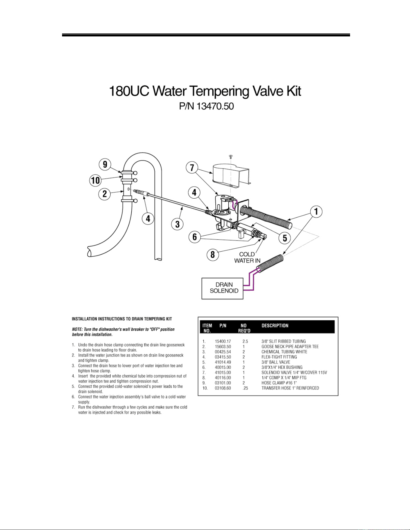
2.2.6. Drain Water Tempering Kit

Getting Started
MODEL CMA-180UC INSTALLATION & OPERATION MANUAL Rev. 1.20 Page
12
2.2.7. Booster Heater Setup (After Jan 2020)
The booster tank must be filled with water before the heating element is energized.
For this reason the “High Limit Switch” has intentionally been disconnected at the
factory and will require re-connection before the heating element will turn on.
Follow the procedure below to complete the initial installation:
1. Close the door on the machine.
2. Turn the Power switch to the "ON" position.
3. On initial setup push Booster Fill button to fill the booster heater.
4. Turn Power switch OFF and On.
The machine will be automatically filled to the correct level.
5. Turn the Power switch to the "OFF" position.
6. Connect blue wire with disconnect, identified by red tag, to the High Limit
Switch which is located below the thermostat behind the front kick panel.
2.2.8. Installers Checklist
Dishmachine checked for concealed damage
Hot water supply is 120° F (49 C) — minimum
Incoming water supply line is ½” — minimum
Supply circuit breaker for machine is properly sized
Service voltage and phase type are correct to machine data plate
If drain pump is used, stand pipe drain should not exceed 22” maximum height
from the floor
Drain hose is installed with air gap (discharge 1” above drain)
Optional detergent and rinse dispenser (if present) is properly installed
Dishmachine is properly grounded
Dishmachine is properly leveled
Machine circuit breaker is labeled “DISHWASHER”
Machine has been “hard-wired” with correctly sized wire
Booster tank has been filled with water (before High Limit Switch is reset)
High Limit Switch for heater has been reset (after Booster Tank has been filled)
2.2.7. Booster Heater Setup (Prior to Jan 2020)
Activating/Adjusting the Booster Heater
1. Booster heater must be filled with water prior to connecting the blue wire
from high limit switch. The high limit switch can be found by removing the
front panel and locating the red button on the front of the heater tank.
2. Once the booster has been connected, the thermostat should be adjusted to
maintain 180°F during the final rinse cycle. The thermostat is located on the
front of the booster tank and is accessible by removing the front panel on the
machine.

Operation
MODEL CMA-180UC INSTALLATION & OPERATION MANUAL Rev. 1.20 Page
13
3. Operation
3.1. Initial Setup
3.1.1. Rinse Pressure Regulator (Models manufactured prior to January
2008 and starting April 2018 to current).
The CMA-180UC requires a supply water input pressure of 24 PSI minimum. This
pressure is then reduced by the supply water regulator. Use the following procedure
to adjust the rinse pressure to 20 PSI:
1. Close the door on the machine. Turn the Power switch to the "ON" position.
2. Machines built prior to January 2020 will be automatically filled to the correct
level.
3. Machines built after January 2020 press and hold the "FILL" button for 25
seconds.
4. Adjust the pressure regulator until the gauge the gauge reads 20 PSI.
Regulator is located behind the front kick panel.
3.1.2. Flow Disc (Models manufactured between January 2008 and April
2018).
Flow Disc has been placed on the exit side of the water valve. The Flow Disc
reduces pressure to the standard recommended 20 PSI.
3.1.3. Rinse and Wash Temperatures
3
1. Turn the Power switch to the "ON" position.
2. After the machine has warmed up for 10-15 minutes, note the wash
temperature. The wash temperature must be 155°F minimum. The rinse
temperature must be 180°F minimum. Rinse temperature will only display
during RINSE section of cycle. If necessary, adjust the temperatures by
removing the front kick panel and turning the thermostat adjustment
clockwise to increase, counterclockwise to decrease. This one adjustment
controls both temperatures.
3.1.4. Post Instructions
1. Install wall chart and instruct machine operator on proper cleaning and
operation of the CMA-180UC.
3.2. Startup Procedures
1. Open the door of the machine and check that the scrap screen is in place, and that
the spray arms and end plugs are secure.
2. Close the door of the machine and turn the Power switch to the "ON" position. The
machine will be automatically filled to the correct level for machines built prior to Jan
2020. Press and hold the "FILL" button for 25 seconds for machines built after Jan
2020.
3. Press the rocker switch marked “START” – the machine will automatically begin its
cycle.
4. Check machine’s operating temperatures — Adjust if necessary. See section 3.1.3
Rinse and Wash Temperatures.

Operation
MODEL CMA-180UC INSTALLATION & OPERATION MANUAL Rev. 1.20 Page
14
5. At the end of the wash period, drain the machine by pressing and holding the
rocker switch marked “DRAIN”. Clean the wash tank screen and scrap tray screen.
Remove and clean the spray arms. (See wall chart instructions).
6. To prime chemical dispensers press and hold down prime switch until product is
discharged into dishmachine.
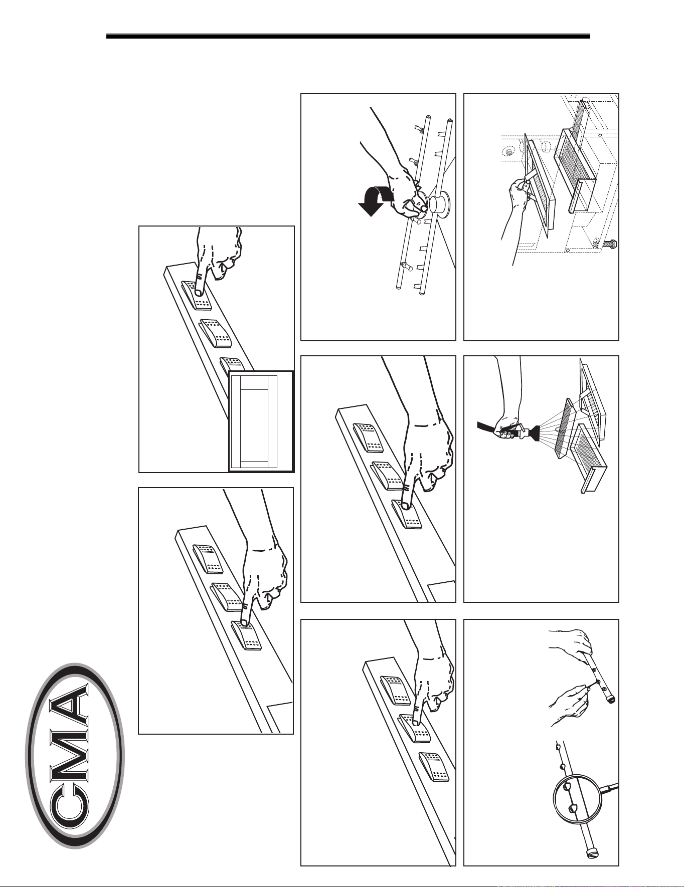
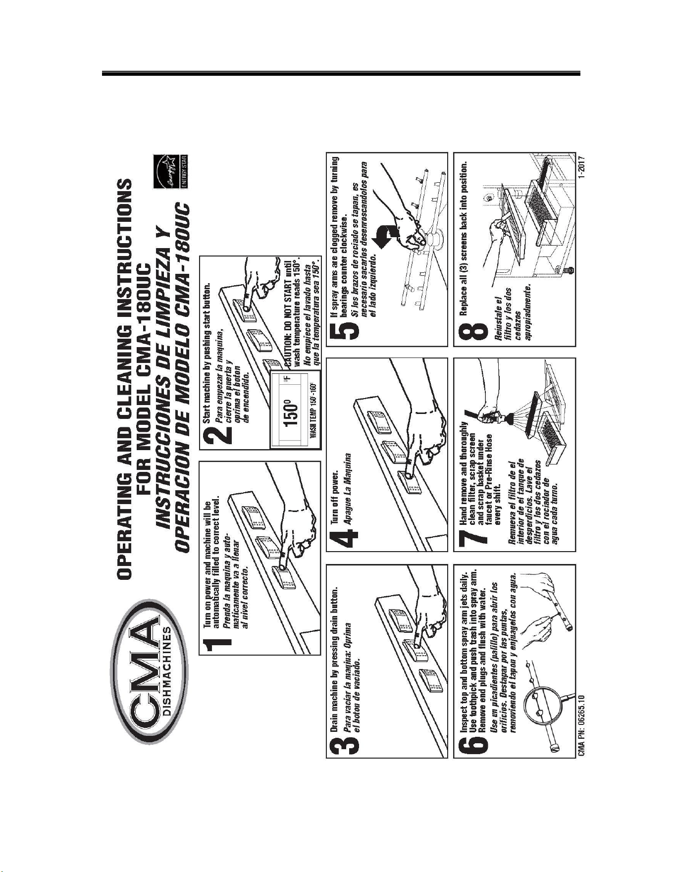
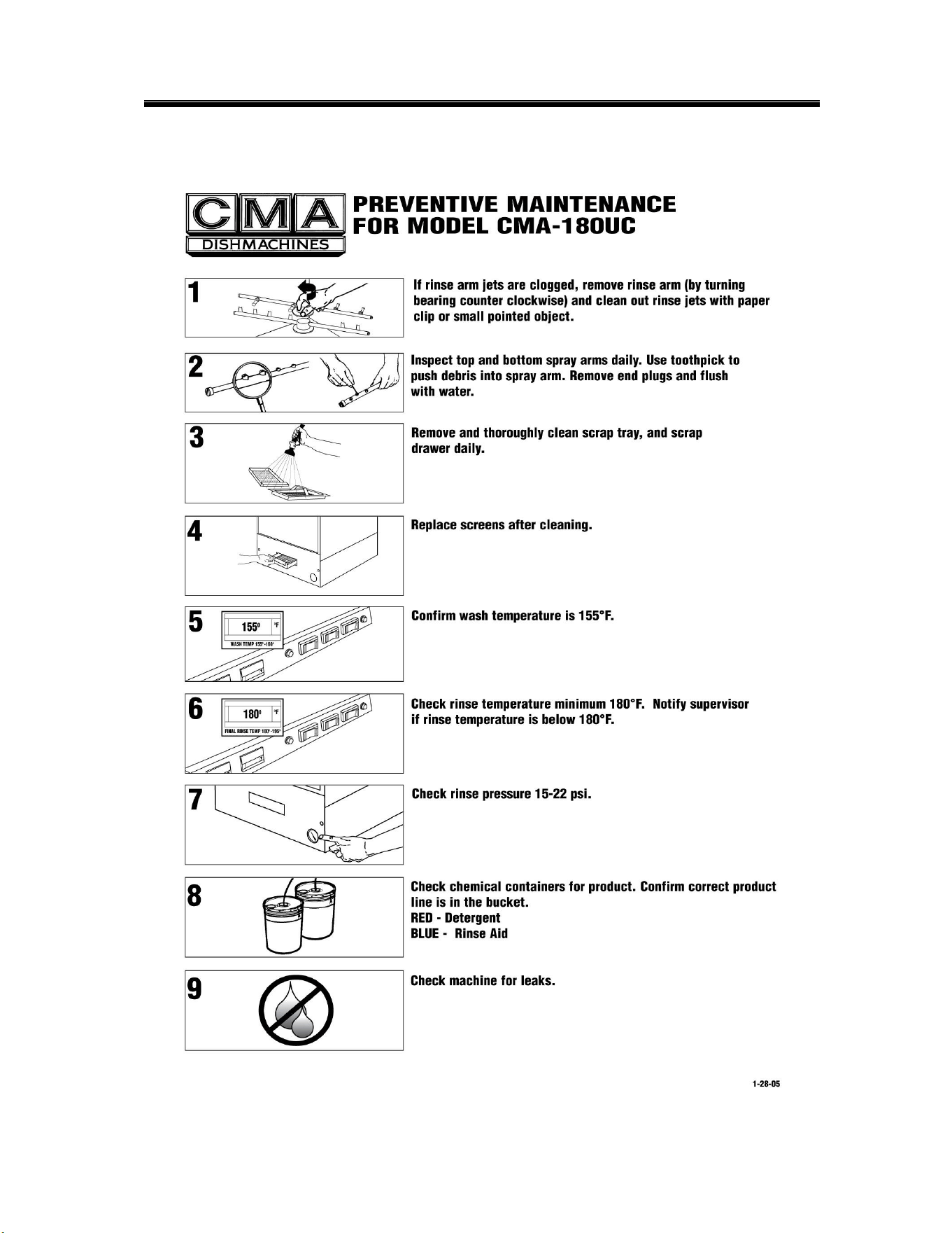
DISHMACHINES
OPERATING AND CLEANING
INSTRUCTIONS FOR MODEL CMA-180UC
INSTRUCCIONES DE LIMPIEZA Y
OPERACION DE MODELO CMA-180UC
Drain machine by pressing
drain button.
Para vaciar la maqina:
Oprima el boton de drenaje.
If spray arms are clogged remove by
turning bearings counter clockwise.
Si los brazos de rociado se tapan,
sera necesario sacarlos
desenroscandolos para el lado
izquierdo.
Inspect top and bottom spray arm jets
daily. Use toothpick and push trash into
spray arm. Remove end plugs and flush
with water.
Use un palillo para abrir los
orificios. Destapar por las puntas,
removiendo el tapon y enjuagelos
con agua.
CMA PN: 06265.10
CAUTION: DO NOT START until
wash temperature reads 150°.
No empiece el ciclo hasta que la
temperatura sea 150°.
Hand remove and
thoroughly clean filter,
scrap screen and
scrap basket under
faucet or Pre-Rinse
Hose every shift.
Remueva el
filtro de
el interior de el
tanque de
desperdicios. Lave el
filtro y los dos
cedazos con el
rociador de agua
cada turno.
Replace all (3) screens back
into position.
Regrese
el
filtro y los
cedazos a
su lugar.
Start machine by pushing start
button.
Para empezar la maquina, cierre la
puerta y
oprima el boton
de encendido.
3
5
Turn off power.
Apague la
maquina.
6
78
2
1
O
F
WASH TEMP 150
0
-160
0
150
O
Turn on power, press and hold FILL
button for 25 seconds
Prenda la maquina y presione el
boton de llenar por 25 segundos.
4
Operation
3.3. Operating and Cleaning Instructions
Operation
MODEL CMA-180UC INSTALLATION & OPERATION MANUAL Rev. 1.20 Page
16
3.3. Operating and Cleaning Instructions
Operation
MODEL CMA-180UC INSTALLATION & OPERATION MANUAL Rev. 1.20 Page
17
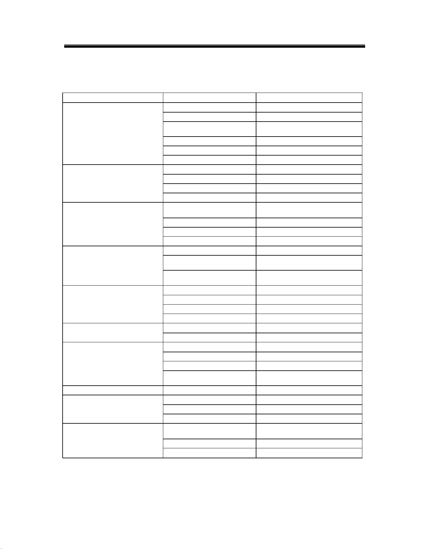
3.4. Preventive Maintenance Chart
Operation
MODEL CMA-180UC INSTALLATION & OPERATION MANUAL Rev. 1.20 Page
18
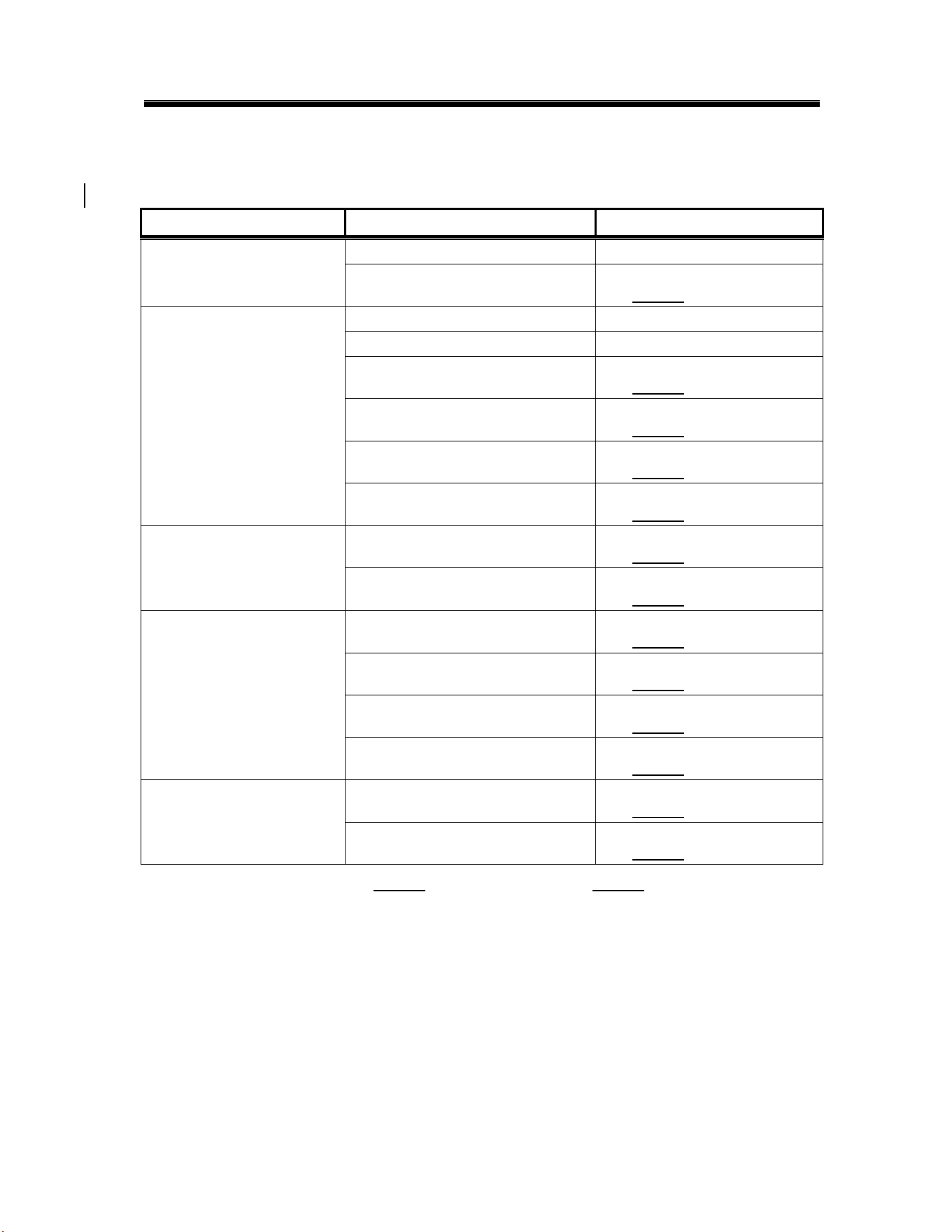
3.5. Quick service guide
MODEL: CMA 180UC HIGH TEMP UNDER COUNTER
TECHNICAL ISSUE
CAUSE
SOLUTION
Pressure regulator is not set properly
Set regulator to 15-25 psi
Faulty rinse micro switch
Replace micro switch, P/N 00411.00
Scrap trap over flows
Drain hose elevated too high
Must be lowered to goose neck level
Obstruction in drain hose
Check hose & clean
Scrap exit screen
Clean exit screen
Faulty drain pump
Replace pump, P/N 15503.00
Machine not level
Adjust machine legs to level
Machine is leaning forward
Adjust machine legs to level
Door leaks
Wash arm end cap missing
Replace end cap, P/N 00308.20
Door gasket
Replace gasket, P/N 14506.60
Loose wire at display, board or
transformer
Secure connectors
Thermometer failure
Faulty temperature sensing wire
Correct, replace, P/N 03202.66
Faulty temperature sensing unit
Replace unit, P/N 03203.00
Faulty transformer
Replace transformer, P/N 03202.60
Scaled heating element
Clean scale from heater
Rinse water temperature low /high
Booster heater’s thermostat not
properly set
Adjust thermostat
Incoming water temperature to
booster heater below 140 F
Adjust external water heater in the facility
Loose lead connections
Check and crimp connectors
Pump motor not running
Faulty # 3 micro switch
Replace micro switch, P/N 00411.00
Faulty contactor
Replace contactor, P/N 15504.00
Faulty wash pump motor
Replace wash pump motor, P/N 00201.00
Pump motor runs continuously
Faulty # 3 micro switch
Replace micro switch, P/N 00411.00
Faulty contactor
Replace contactor, P/N015504.00
Water regulator not adjusted properly
Adjust regulator to 18-20 PSI
Low water pressure at the final rinse
Clogged final rinse spray jets
Clean jets
Missing final rinse spray end cap
Replace end cap, P/N 00308.17
Low incoming water pressure from
facility
Increase pressure to 18-20 psi
Scrap trap overflows over night
Faulty water solenoid diaphragm
Clean or replace diaphragm, P/N 00706.00
Low wash or rinse water temp.
Check temperature settings
Poor cleaning results
Wash arm bearing or jets
Clean bearing and arm jets
Rinse arm bearing or jets
Clean bearing and arm jets
Tank discharge screen dirty
Clean screen
Wash tank will not drain.
Drain valve not operating
Check power to drain valve
Drain valve faulty
Replace Drain valve, P/N 04103.00
Operation
MODEL CMA-180UC INSTALLATION & OPERATION MANUAL Rev. 1.20 Page
19
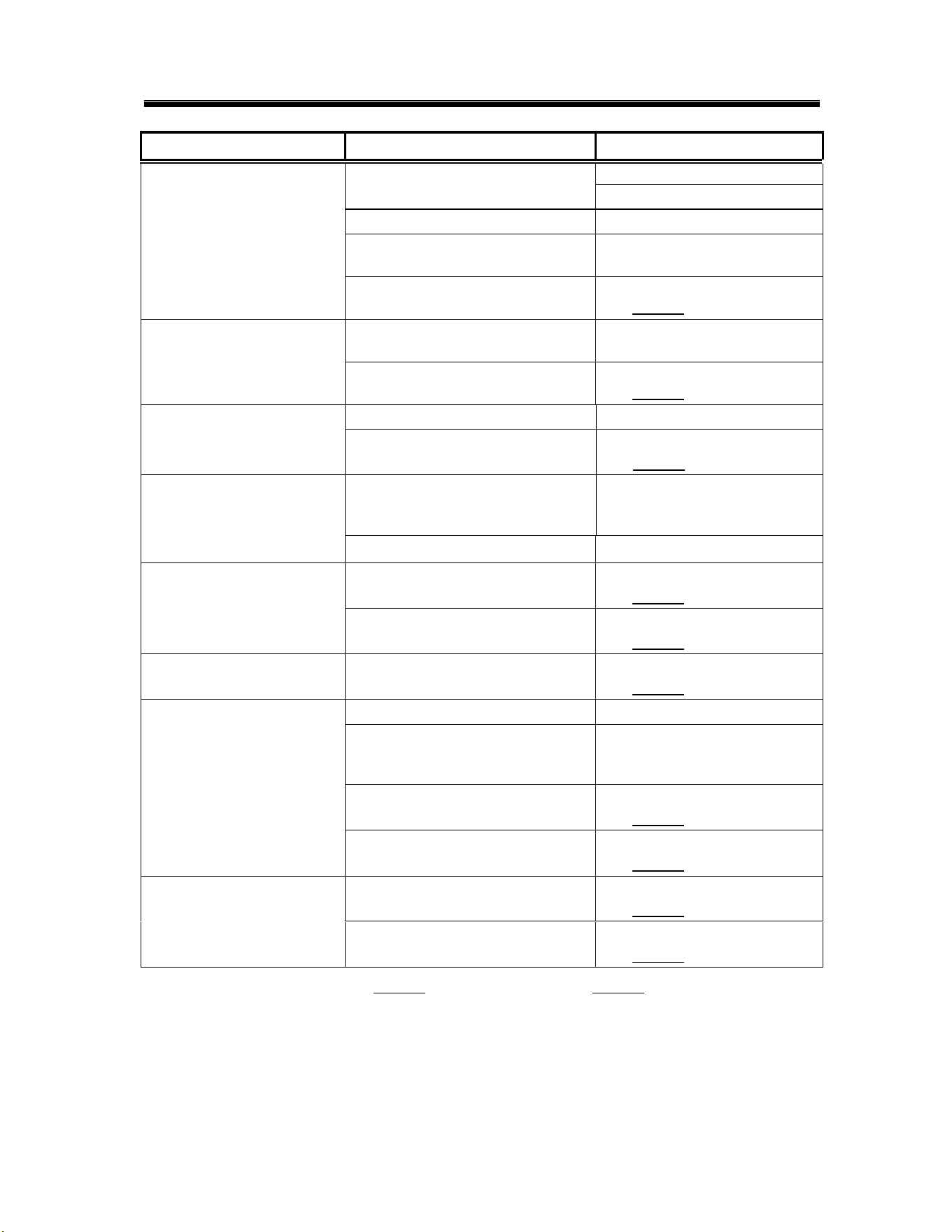
3.6. Troubleshooting
PROBLEM
LIKELY CAUSE
SOLUTION
Machine inoperative
Power off at circuit breaker
Reset circuit breaker
Defective power switch
Replace power switch
P/N: 15521.50
Motor inoperative
Door is open
Close door
Control panel is pulled out
Secure control panel
Defective reed switch
Replace reed switch
P/N: 00557.55
Defective timer assembly
Replace timer assembly*
P/N: 14408.80
Defective pump motor contactor
Replace contactor
P/N: 15504.00
Defective motor
Replace motor
P/N: 00201.66
Motor runs with door open
Defective reed switch
Replace reed switch
P/N: 00557.55
Defective pump motor contactor
Replace contactor
P/N: 15504.00
Heater (no heat)
High limit switch opened or
defective
Reset or replace switch
P/N: 17523.51
Defective thermostat
Replace thermostat
P/N: 13417.89
Defective heater contactor
Replace heater contactor
P/N: 15504.50
Defective heater
Replace heater
P/N: 15517.00
Heater (never turns off)
Defective thermostat
Replace thermostat
P/N: 13417.89
Defective heater contactor
Replace heater contactor
P/N: 15504.50
*The timer assembly motor (P/N: 00501.00) or micro switches (P/N: 00411.00) can be replaced
independently if that’s the only component that’s failed.
Operation
MODEL CMA-180UC INSTALLATION & OPERATION MANUAL Rev. 1.20 Page
20
PROBLEM
LIKELY CAUSE
SOLUTION
Low heat during operation
Low incoming water temperature
(below 140° F)
Turn up supply water heater
Insulate supply water pipe
Thermostat out of adjustment
Adjust thermostat
Cold water mixing with supply
Isolate hot water from cold
water
Defective heater
Replace heater
P/N: 15517.00
Low rinse water pressure
Pressure regulator out of
adjustment
Adjust pressure regulator
Defective pressure gauge (actual
pressure is okay)
Replace pressure gauge
P/N: 13605.45
Regulator at maximum but
rinse pressure still low
Insufficient water supply flow
Supply larger supply line
Defective water solenoid valve
Replace water solenoid valve
P/N: 00705.00
Low rinse water flow
Low rinse water pressure
See “Low rinse water
pressure” in PROBLEM
column
Limed up rinse arm spray nozzles
De-lime rinse arm nozzles
No rinse water flow
Defective water solenoid valve
Replace water solenoid valve
P/N: 00705.00
Defective (Rinse Relay) ice cube
relay
Replace ice cube relay
P/N: 00631.00
Rinse water runs with door
open
Defective reed switch
Replace reed switch
P/N: 00557.55
Water overflows scrap tray
onto floor
Drain hose is kinked
Un-kink drain hose
Drain hose is not properly
elevated before dropping to drain
(if drain pump is used)
Elevate drain hose 12 to 16”
above pump before dropping
to drain
Defective timer assembly
Replace timer assembly*
P/N: 14408.80
Defective drain pump
(if drain pump is used)
Replace drain pump
P/N: 15503.00
With power on, activating
start switch does not begin
cycle
Defective start switch (cycle light
will not light either)
Replace start switch
P/N: 15521.00
Defective timer assembly
Replace timer assembly*
P/N: 14408.80
*The timer assembly motor (P/N: 00501.00) or micro switches (P/N: 00411.00) can be replaced
independently if that’s the only component that’s failed.
Operation
MODEL CMA-180UC INSTALLATION & OPERATION MANUAL Rev. 1.20 Page
21
PROBLEM
LIKELY CAUSE
SOLUTION
Start switch requires > 3
second activation to run
cycle
Defective (Instant Start) ice cube
relay
Replace ice cube relay
P/N: 00631.00
Pressing and holding fill
switch does not fill
machine
Defective drain/fill switch
Replace drain/fill switch
P/N: 15522.00
Defective water solenoid valve
Replace water solenoid valve
P/N: 00705.00
Fill (rinse water) won’t shut
off
Defective water solenoid valve
Replace water solenoid valve
P/N: 00705.00
Defective drain/fill switch
Replace drain/fill switch
P/N: 15522.00
Defective timer assembly
Replace timer assembly*
P/N: 14408.80
Defective (Rinse Relay) ice cube
relay
Replace ice cube relay
P/N: 00631.00
Pressing and holding
drain switch does not
drain machine
Drain hose is kinked
Un-kink drain hose
Defective drain/fill switch
Replace drain/fill switch
P/N: 15522.00
Defective drain valve
Replace drain valve
P/N: 04103.00
Cycle light does not light
while cycle runs
Defective cycle light
Replace cycle light (green)
P/N: 00406.60
Power light does not light
but machine runs
Defective power light
Replace power light (red)
P/N: 00406.00
Wash tank or final rinse
temperature does not
display
Defective digital thermometer
Replace digital thermometer
P/N: 03202.45
Both the wash tank
temperature and the final
rinse temperature do not
display
Defective thermometer
transformer
Replace thermometer
transformer
P/N: 03202.60
Wash tank or final rinse
displays wrong
temperature
Defective digital thermometer
Replace digital thermometer
P/N: 03202.45
Defective thermister
Replace thermister
P/N: 03202.65
Operation
MODEL CMA-180UC INSTALLATION & OPERATION MANUAL Rev. 1.20 Page
22
4. Parts Kit
4.1. Initial Parts Kit (P/N 1100.66)
P/N
DESCRIPTION
Qty
15504.00
Motor Contactor, 2-Pole 20 Amp
1
15504.50
Heater Contactor, 2-Pole 35 Amp
1
00501.00
2-Minute Timer Motor
1
00631.00
Ice Cube Relay 120 V
1
00707.00
½ Water Solenoid Repair Kit JE
1
00738.15
Solenoid Coil JE 220V
1
15523.00
Rocker Switch Start Momentary
1
15523.50
Rocker Switch Drain/Fill
1
15524.00
Rocker Switch Power Maintained
1
00556.10
Reed Switch
1
03623.00
1/2” Vacuum Breaker Repair Kit – Watts
1
00707.00
1/2” Water Solenoid Repair Kit – J/E
1
04113.00
L1X/L1-C Drain Valve 120V
1
00206.70
Pump Seal Kit
1
13417.89
Heater Thermostat
1
17523.60
High Limit Switch 200°F
1
00411.00
Microswitch
1
03203.01
Dual Temperature Display Kit
1
00738.15
Solenoid Coil JE 115V/60Hz
1
Operation
MODEL CMA-180UC INSTALLATION & OPERATION MANUAL Rev. 1.20 Page
23
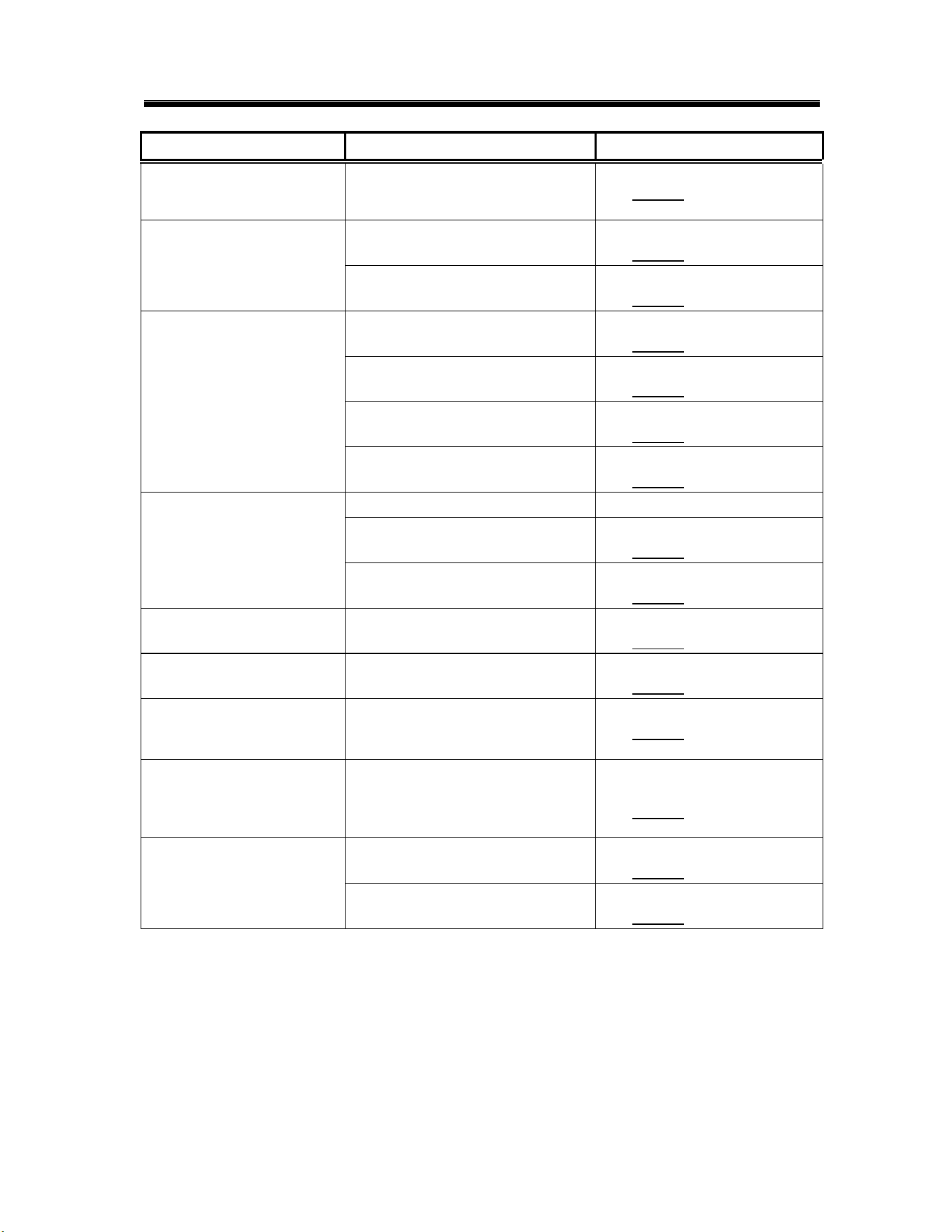
4.2. Drain Pump
ITEM
NO.
NO.
REQ’D
P/N
DESCRIPTION
ITEM
NO.
NO.
REQ’D
P/N
DESCRIPTION
1
1
15503.00
Drain Motor Ultra Jet for CMA-180UC
6
4
03101.00
Hose Clamp 1”
2
2
00932.50
Twist Tie
7
1
15603.00
Drain Line Gooseneck
3
1
15601.10
Black Drain Hose 1" ID X 3 1/2"
8
2
03801.10
10-32 SS Nut
4
1
15605.00
Drain Hose with Goose Neck
9
2
04806.00
#10 Brass Washer
5
1
15601.60
Robber Hose 90 Deg.
Operation
MODEL CMA-180UC INSTALLATION & OPERATION MANUAL Rev. 1.20 Page
24
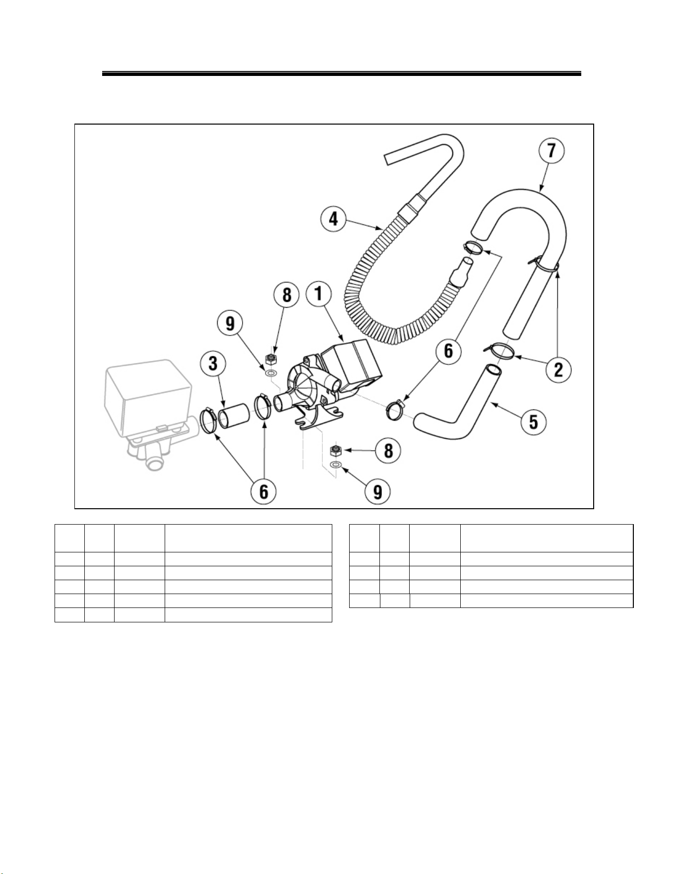
4.3. Drain Pump Removal Instructions
Drain Pump (P/N 15503.00) should only be used if a floor drain is not accessible to
the machine at installation.
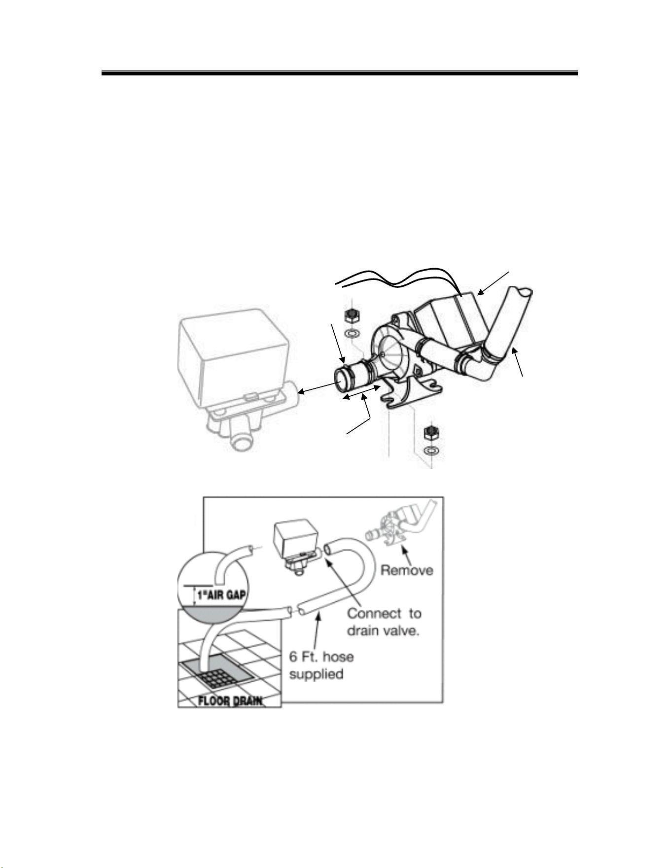
When converting the UC-180 dishwasher to a gravity drain unit, remove the drain pump
assembly as shown in Figure 1. Re-route the 6Ft drain hose to the center port were the
drain pump was located, moving the displaced line to the open port of the valve. Insure
there is a 1” air gap between the discharge and floor drain as shown in Figure 2.
Figure 1
Figure
Figure 2
Disconnect
purple and white
wires
Remove this cover to
disconnect the wires
Remove this
hose clamp
over Drain
Valve.
Disconnect 3-
inch pump inlet
drain hose.
Remove drain hose from
the drain gooseneck
Operation
MODEL CMA-180UC INSTALLATION & OPERATION MANUAL Rev. 1.20 Page
25
5. Customer Notice
CMA-180UC Installation Guidelines
Improper installation of this product may void the warranty on this machine. Please follow
these guidelines for recommended installation and to ensure the warranty of this model is
authorized by CMA Dishmachines.
Dishmachine Installation Requirements
1. Machine must be level. Adjust leveling feet to accommodate uneven floor
surfaces.
2. Stand pipe drain height should not exceed maximum height of 22”.If there is
a floor drain, it is highly recommended the pump drain be removed. Connect
supplied drain line to 3-way valve on back of machine and gravity feed to the
floor drain.
3. Approximately 4-feet of ¾” flexible conduit with power leads (L-1, L-2,
Neutral and Ground) extending out of the conduit are provided for easily
connecting the power at installation. CMA recommends a minimum 50-amp
dedicated circuit, but you should consult your local building code
requirements for proper breaker size.
Activating/Adjusting the Booster Heater
1. Booster heater must be filled with water prior to connecting the blue wire
from high limit switch. The high limit switch can be found by removing the
front panel and locating the red button on the front of the heater tank.
2. Once the booster has been connected, the thermostat should be adjusted to
maintain 180°F during the final rinse cycle. The thermostat is located on the
front of the booster tank and is accessible by removing the front panel on the
machine.
Automatic Dispensing Equipment
Applications utilizing automated dispensers for administering warewash
chemicals must use 110v dispenser equipment. There is a 110v power block
for installing this equipment inside the control panel.
Electrical
Diagrams
MODEL CMA-180UC INSTALLATION & OPERATION MANUAL Rev. 1.20 Page
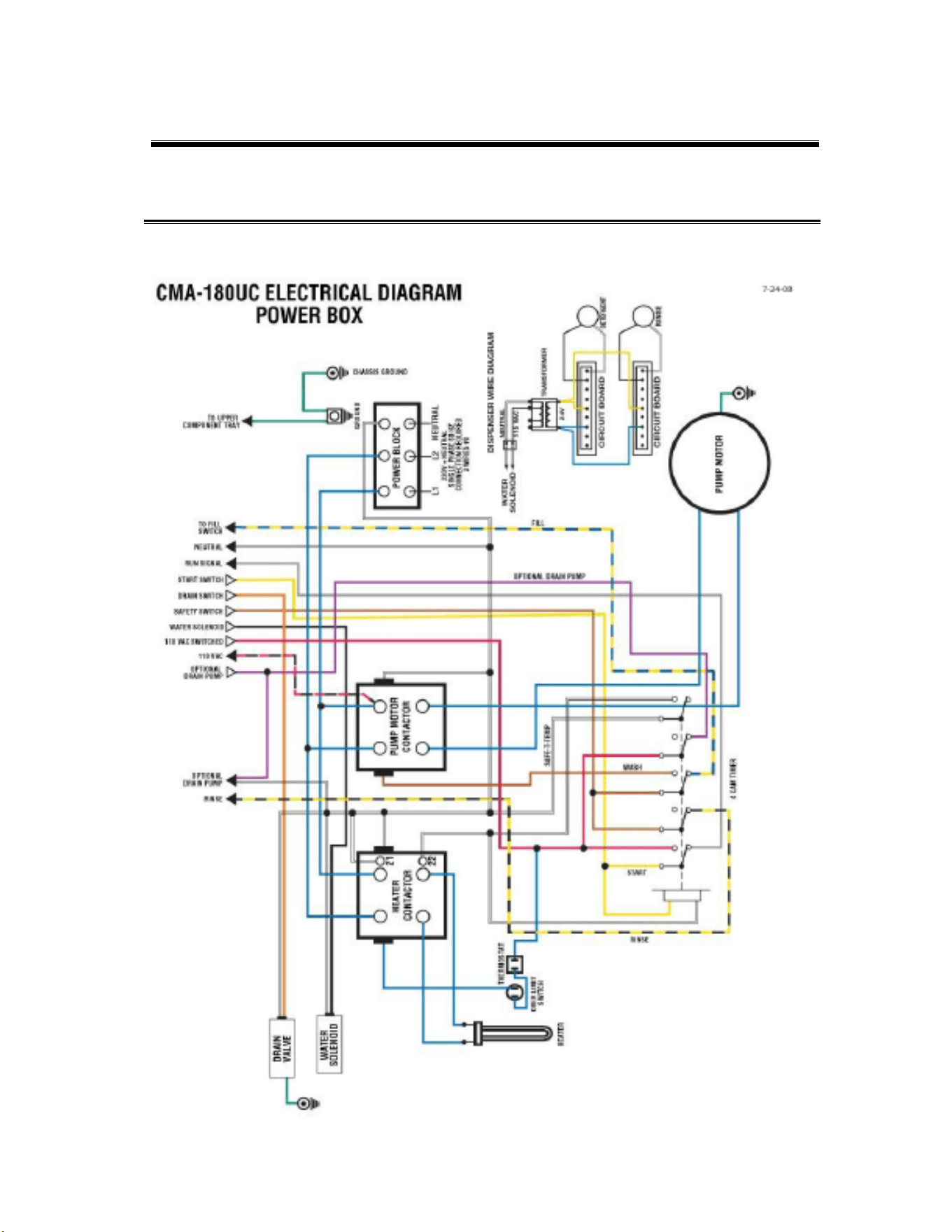
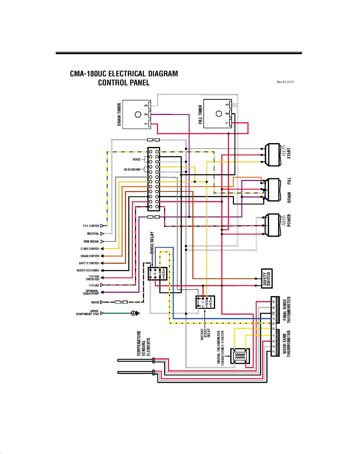
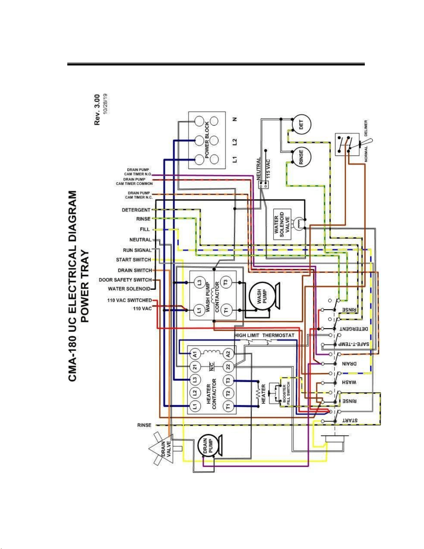
26
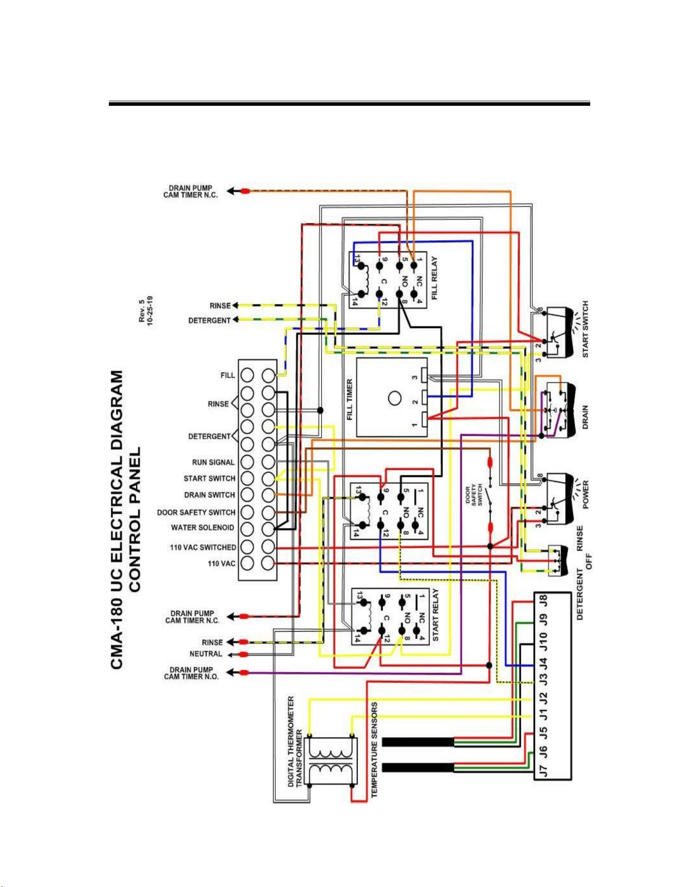
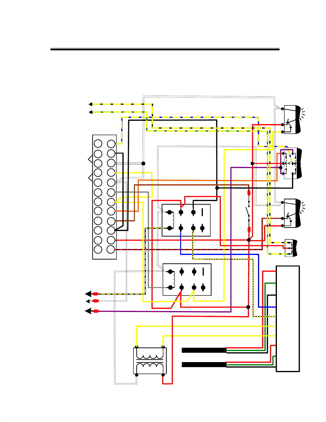
6. Electrical Diagrams
Electrical
Diagrams
MODEL CMA-180UC INSTALLATION & OPERATION MANUAL Rev. 1.20 Page
27
Electrical
Diagrams
MODEL CMA-180UC INSTALLATION & OPERATION MANUAL Rev. 1.20 Page
28
Electrical
Diagrams
MODEL CMA-180UC INSTALLATION & OPERATION MANUAL Rev. 1.20 Page
29
Effective January 2018 to January 2020.
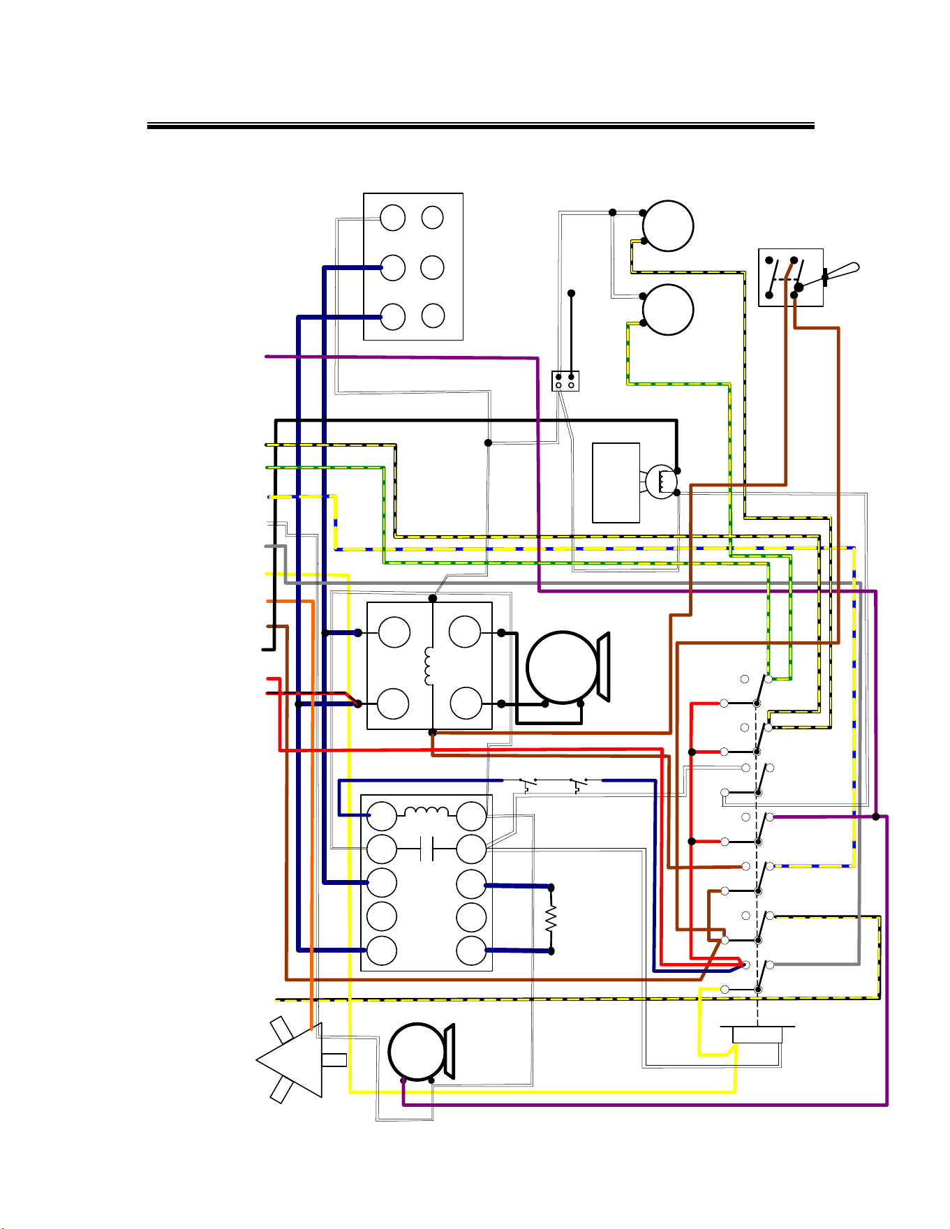
START
RINSE
WASH
DRAIN
SAFE-T-TEMP
WATER
SOLENOID
VALVE
HEATER
CONTACTOR
L1 L2 L3 A1
T1 T2 T3 A2
N/C
21
22
DRAIN
VALVE
DRAIN
PUMP
H
I
G
H
L
I
M
I
T
T
H
E
R
M
O
S
T
A
T
HEATER
L1 NL2
POWER BLOCK
1
1
0
V
A
C
1
1
0
V
A
C
S
W
I
T
C
H
E
D
W
A
T
E
R
S
O
L
E
N
O
I
D
D
O
O
R
S
A
F
E
T
Y
S
W
I
T
C
H
D
R
A
I
N
S
W
I
T
C
H
S
T
A
R
T
S
W
I
T
C
H
R
U
N
S
I
G
N
A
L
N
E
U
T
R
A
L
T1
T3
L1
L3
WASH PUMP
CONTACTOR
WASH
PUMP
F
I
L
L
R
I
N
S
E
D
R
A
I
N
P
U
M
P
C
A
M
T
I
M
E
R
N
.
O
.
115 VAC
NEUTRAL
CMA-180 UC ELECTRICAL DIAGRAM
POWER TRAY
Rev. 4.00
12/11/19
RINS
E
DET
NORMAL
DELIMER
D
E
T
E
R
G
E
N
T
R
I
N
S
E
RINSE
DETERGENT
Electrical
Diagrams
MODEL CMA-180UC INSTALLATION & OPERATION MANUAL Rev. 1.20 Page
30
Effective January 2020.
NC
NO
C
1 4
8
5
9
12
14
13
NC
NO
C
1 4
8
5
9
12
14
13
DRAIN FILL
23
8
POWER
23
8
START SWITCH
J7 J6 J5 J1 J2 J3 J4 J10 J9 J8
START RELAY
DOOR
SAFETY
SWITCH
DIGITAL THERMOMETER
TRANSFORMER
TEMPERATURE SENSORS
1
1
0
V
A
C
1
1
0
V
A
C
S
W
I
T
C
H
E
D
W
A
T
E
R
S
O
L
E
N
O
I
D
D
O
O
R
S
A
F
E
T
Y
S
W
I
T
C
H
D
R
A
I
N
S
W
I
T
C
H
S
T
A
R
T
S
W
I
T
C
H
R
U
N
S
I
G
N
A
L
F
I
L
L
D
E
T
E
R
G
E
N
T
R
I
N
S
E
D
R
A
I
N
P
U
M
P
C
A
M
T
I
M
E
R
N
.
O
.
R
I
N
S
E
N
E
U
T
R
A
L
CMA-180 UC ELECTRICAL DIAGRAM
CONTROL PANEL
Rev. 7
12-12-19
DETERGENT RINSE
OFF
R
I
N
S
E
D
E
T
E
R
G
E
N
T
RINSE RELAY
Electrical
Diagrams
MODEL CMA-180UC INSTALLATION & OPERATION MANUAL Rev. 1.20 Page
31
Effective January 2020.