2019-08
Syringe Pump Type SS3 OTCI
TE-SS830P
Instruction Manual
Store this instruction manual in a convenient location for future reference whenever
necessary. Read the instructions carefully before using the product, and operate in
accordance with instructions. Perform maintenance and inspections to ensure safe
use and extend the life of this product.

2
Read this instruction manual carefully to fully understand this product and ensure its safe use. For an explanation regarding the
introduction of this product, consult with TERUMO trained service technicians. Conduct safety training sessions for this product
before use.
Contents
Contents
Purpose, Overview and Features of the Product 3
Purpose and Overview ........................................... 3
How the pump works in the TCI mode ................... 3
Features ................................................................. 4
Unit Correlation ...................................................... 5
Glossary of terms ................................................... 5
Parts Description 6
Exterior Diagram .................................................... 6
Operation Panel ..................................................... 7
Screen Description ................................................. 8
Standard Accessories ........................................... 17
Optional Accessories ............................................ 17
Precautions 19
Use ....................................................................... 19
Compatible Syringes 24
Preparation 25
Prior to the Pump being Used .............................. 25
Prior-to-use Inspection ......................................... 25
Attaching/Detaching a Pole Clamp ....................... 27
Attaching/Detaching to the IV Pole ....................... 28
Connecting to AC Power ...................................... 29
Operating by the Internal Battery ......................... 30
Operation Procedure 31
Using the TCI mode.................................................. 31
Turning the Power On .......................................... 31
Setting the Syringe ............................................... 32
Selecting the TCI mode ........................................ 35
Priming ................................................................. 38
Inserting a Needle ................................................ 39
Starting Solution Delivery ..................................... 39
Changing the target concentration (Cpt or Cet) ... 41
Changing the decrement concentration ............... 42
Changing Scales .................................................. 43
Replacing the Syringe .......................................... 45
Ending the TCI mode ........................................... 47
Turning the Power Off .......................................... 49
Using other dose modes .......................................... 50
Turning the Power On .......................................... 50
Setting the Syringe ............................................... 51
Setting Flow Rate ................................................. 55
Setting VTBI ......................................................... 56
Setting VTBI Time ................................................ 57
Priming ................................................................. 58
Inserting a Needle ................................................ 59
Starting Solution Delivery .................................... 60
Stopping Solution Delivery ................................... 61
Replacing Syringe to Continue Solution Delivery
........................................................................... 62
Turning the Power Off .......................................... 63
Other Operation Procedures 64
Clearing the Volume Delivered (except the TCI
mode) ................................................................. 64
Standby Function ................................................. 65
Selecting Dose Mode (Drug Library) .................... 66
Setting Special Functions ..................................... 73
Changing Settings on the Menu 79
Occlusion Detection Pressure .............................. 80
Keypad Lock Function .......................................... 83
Bolus (except the TCI mode) ................................ 86
Maximum flow rate setting (TCI mode only) ......... 92
Plasma limit setting (TCI mode only) .................... 94
Advanced Dose Mode .......................................... 96
History Function ................................................. 100
TCI operation history function ............................ 103
Changing the Sound Volume .............................. 105
Changing the Brightness .................................... 108
Setting the Date and Time ...................................110
Profile ..................................................................112
Communication Environment ..............................114
About External Communication Functions 118
Overview .............................................................118
Network System Connection ...............................119
After Use 128
Cleaning ............................................................. 128
How to Clean Components ................................ 129
Storage ............................................................... 131
Maintenance and Inspections 132
Maintenance and Inspection Items by TERUMO
Certified Service Technicians ........................... 132
Waste and Recycle............................................. 132
Troubleshooting 133
Troubleshooting procedure................................. 133
High priority alarm .............................................. 135
Medium priority alarm ......................................... 139
Low priority alarm ............................................... 139
Other problems ................................................... 143
Specifications 146
Units Available .................................................... 153
Device Characteristics 154
Flow Rate Characteristics .................................. 154
Occlusion Characteristics ................................... 155
For Medical Staff 156
EMC Technical Information ................................ 156
Symbols 161
Other Information 162
Memo 163
FOR INFORMATION ABOUT TERUMO
PRODUCTS 164
3
Purpose and Overview
The TERUFUSION Syringe Pump Type SS3 OTCI is intended for the infusion of general and local anesthetics, vasodilators,
cardiotonics, parenteral feeding, anti-cancer drugs, labor-inducing drugs and blood transfusion at ICU, CCU, NICU, operating
rooms or general wards.
This equipment is intended to be used to inject a drug solution from a syringe constantly at a preset hourly flow rate.
Additionally, this product can be used in the TCI mode, which is equipped with predictive models of the drug action (PK/PD) with
three compartments.
* PK/PD Theory: To analyze the drug action by pharmacokinetics (PK) and/or pharmacodynamics (PD).
Model Catalogue number Communication function Hereinafter referred to as
TE-SS830P
TE
*
SS835Pxx
Infrared communication (IrDA), Wireless LAN TE-SS830P
Alphanumeric characters are entered for x in the catalogue number.
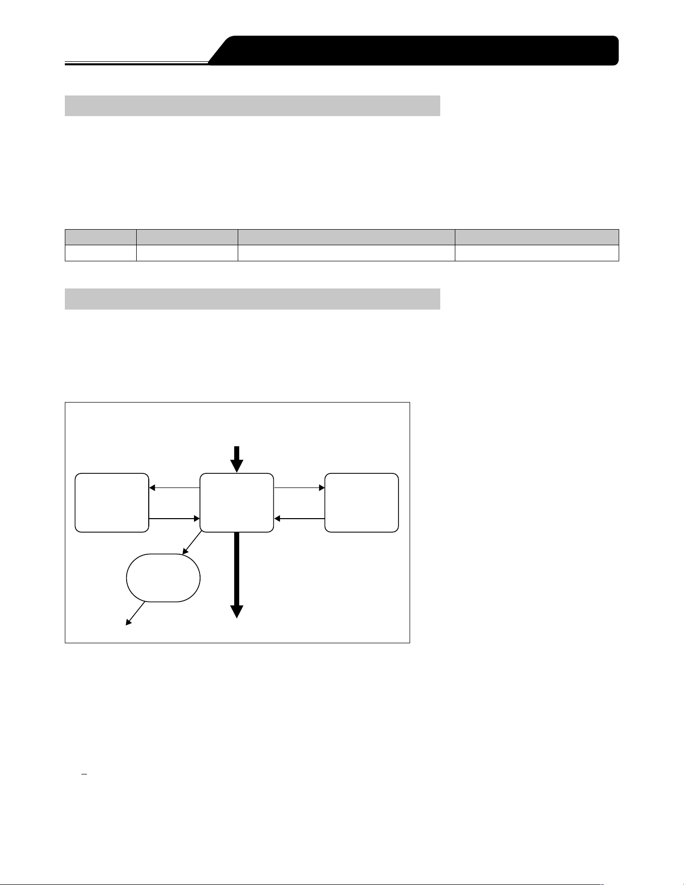
How the pump works in the TCI mode
In the TCI (Target Controlled Infusion) mode, the pump calculates and controls the flow rate to achieve and maintain the
predetermined (target) drug concentration in a patients body based on a mathematical model, called a compartment model,
which simulates drug absorption, distribution, and clearance (pharmacokinetics) and the drug effect on the site of action
(pharmacodynamics) in the human body.
This product analyzes the drug action by using the PK/PD models based on a three-compartment model as shown below:
Mô hình 3 buồng
Thuốc vào
k
12
k
13
k
21
k
31
k
1e
k
10
Vùng
ngoại vi
V2
Vùng
trung tâm
V1
Vùng
ngoại vi
V3
Vùng não
Giải phóng
k
e0
Vùng trung tâm V1: A compartment where drug is input, principally plasma
Peripheral compartment V2: A vessel-rich rapidly distributing compartment such as muscle
Peripheral compartment V3: A vessel-poor slowly distributing compartment such as fatty tissue
Effect-site compartment: A theoretical concept describing drug effect in the brain, considered to have no volume
Used for effect-site TCI
k
21
, k
31
: Distribution (drug transfer) rate constant to the central compartment V1
k
12
: Distribution rate constant to the peripheral compartment V2
k
13
: Distribution rate constant to the peripheral compartment V3
k
10
: Clearance (elimination) rate constant from the central compartment
k
e0
(~ k
1e
): Transport rate between the central compartment and the effect-site compartment
This product provides five TCI modes in combinations of drugs (Propofol and Remifentanil), PK/PD models (Marsh, Schnider, and
Minto), and targets (plasma targeting and effect-site targeting).
Purpose, Overview and Features of the Product

4
Purpose, Overview and Features of the Product
The rate constants of each PK/PD model are as follows:
Tốc độ
không đổi
Propofol
(Marsh)
Propofol (Schnider) Remifentanil (Minto)
Vc (V1) [L] 0.228 x Weight 4.27 5.1-0.0201 x (Age-40)+0.072 x (LBM-55)
k
10
[/min] 0.119 [1.89+((Weight-77) x 0.0456)+((59 x 0.0681)-
(LBM x 0.0681))+((Height-177) x 0.0264)]/Vc
[2.6-0.0162 x (Age-40)+0.0191 x (LBM-55)]/
Vc
k
12
[/min] 0.112 [1.29-0.024 x (Age-53)]/Vc [2.05-0.0301 x (Age-40)]/Vc
k
13
[/min] 0.0419 0.836/Vc [0.076-0.00113 x (Age-40)]/Vc
k
21
[/min] 0.055 [1.29-0.024 x (Age-53)]/[18.9-0.391 x (Age-53)] [2.05-0.0301 x (Age-40)]/[9.82-0.0811 x
(Age-40)+0.108 x (LBM-55)]
k
31
[/min] 0.0033 0.0035 [0.076-0.00113 x (Age-40)]/5.42
k
e0
[/min] 0.26 0.456 0.595-0.007 x (Age-40)
Tài liệu tham
khảo
Marsh et al.:
British Journal
of Anaesthesia
1991; 67: 41-48
Schnider et al.: Anesthesiology 1999; 90:
1502 - 1516
Anesthesiology 1998; 88:
1170 - 1182
Minto et al.: Anesthesiology 1997; 86:
10 - 23
Features
TCI mode
TCI (Target Controlled Infusion) can be performed with this product in the following five different combinations of drugs, models,
and targets:
For Plasma TCI, Propofol (Marsh), Propofol (Schnider), and Remifentanil (Minto) are available.
For Effect-site TCI, Propofol (Schnider) and Remifentanil (Minto) are available.
Dose unit
The flow rate (mL/h) can be automatically calculated based on the dose units such as μg/kg/min. The calculated contents of the
flow rate can be checked on the screen.
Easy-to-read display
With a 4.3 inch (10.9 cm) colour LCD, clear and precise visibility has been achieved.
The operation indicator allows the operation/stop/alarm status to be easily recognised.
The internal battery charge and level indicator is displayed on the LCD with 5 bars.
Wide range of alarm functions
The alarm functions include Occlusion alarm, Pressure alarm, Nearly Empty alarm, Slider Displacement alarm, Syringe Barrel
Detection alarm, Syringe Displacement alarm, Link Interruption alarm, Plunger Displacement alarm, Battery alarm, Shutdown
Notice alarm, Power Failure alarm, Re-alarm, Start Reminder, No Flow Rate alarm, No VTBI alarm*
1
, Flow Rate/VTBI (Volume to
be infused) Volume Judgment alarm*
1
and Completion alarm*
1
.
*
1
: Only if the VTBI setting function is enabled (Default: disabled)
The Occlusion alarm detection sensitivity level can be changed according to the condition of use.
The Flow Rate/VTBI Volume Judgment alarm works as a safety function to prevent the normal mode operation if the flow rate is
equal to or more than the VTBI. (Default: disabled)
Additional safety functions
The keypad lock function disables any switch operations after being set to prevent any operational errors or inadvertent
operations. (Except for Start switch, Power switch and Back/Mute switch (for operation to release the keypad lock).)
User-friendly shape and structure
With a unit weight of approx. 2.0 kg, the carrying burden is reduced, and allows for stable installation with the pole clamp
included.
The rounded-cornered body is easy to clean even when drug solution has adhered.
Dual power supply system
Dual power supply system with AC power and internal battery
The internal battery can provide approx. 8 hours of continuous operation for solution delivery at a flow rate of 5 mL/h at
temperature of 25°C, with a fully-charged new battery.
The internal battery can be charged to approx. 80% in 3 hours.
The sub-battery is used for a Power Failure alarm in case both power supplies are lost.

5
Purpose, Overview and Features of the Product
Communication function
The infrared communication allows communication with the optional Communication Rack System*
2
.
The wireless LAN allows communication with the network system.
*
2
: TERUFUSION Communication Rack System (Model: TE-RS800)
TERUFUSION Communication Rack System (Extension) (Model: TE-RS811)
Unit Correlation
mcg/kg/min and μg/kg/min have the same meaning and are interchangeable.
Glossary of terms
Decrement (awakening) time: The time required for the predicted concentration level to reach the decrement
concentration level. The value of decrement concentration should be set in advance. See Changing the decrement
concentration (page 42).
Effect-site TCI: TCI mode targeting effect-site concentration.
Plasma TCI: TCI mode targeting plasma (blood) concentration.
Predicted effect-site concentration: Predicted value of drug concentration in the brain (effect-site concentration).
Calculated based on the selected drug, model, the patient information such as body weight, and the target effect-site
concentration (Cet).
Predicted plasma concentration: Predicted value of concentration of drug in the blood. Calculated based on the selected
drug, model, the patient information such as body weight, and the target plasma concentration (Cpt).
TCI mode: A dose mode for TCI (Target Controlled Infusion). The pump calculates infusion flow rates based on the
selected drug, model, target (plasma or effect-site targeting), and the patient information such as body weight to achieve
and maintain the target drug concentration.
6
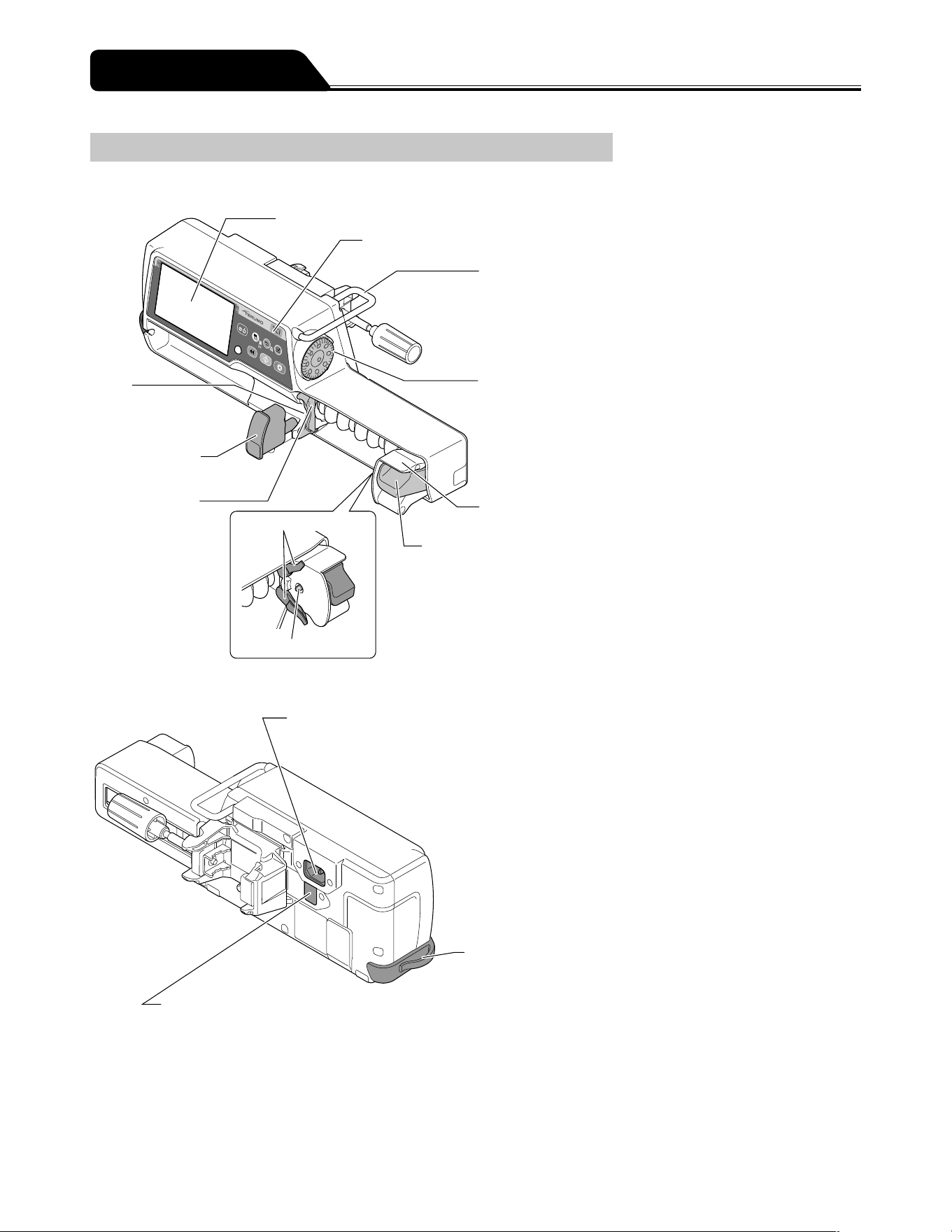
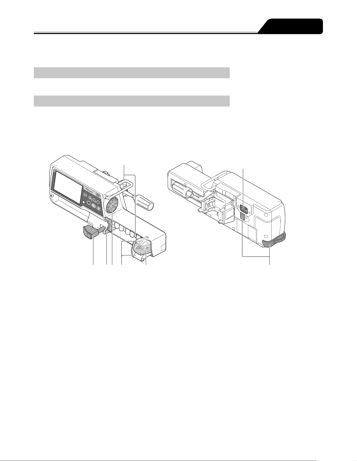
Exterior Diagram
Front view
● LCD
● Operation panel
● Handle
Holds the pump main unit.
● Dial
Sets the flow rate,
dosage, weight, etc.
Selects (Up/Down) the item in the menu.
The increase/decrease range
varies according to the rotation
speed.
● Slider
● Clutch
● Slit
Accepts the flange
of a syringe.
● Syringe clamp
Fixes the syringe.
● Flange holder
Holds the flange of
a syringe.
● Plunger detector
● Slider hook
Rear view
● AC inlet
Connects with the
AC power cable.
● Tube holder
● Infrared communication window
Communicates with the optional
Communication Rack System*
1
.
*
1
: TERUFUSION Communication Rack
System (Model: TE-RS800)
TERUFUSION Communication Rack
System (Extension) (Model: TE-RS811)
Parts Description

7
Parts Description
Operation Panel
● Display select switch
● Power switch
● Back/Mute switch
● Confirmation switch
● Stop switch
● Start switch
● Operation indicator
● Purge switch
Name Function
Power switch
Turns the power ON/OFF.
Purge switch
In the stop status, press and hold this switch to perform a rapid infusion.
In the bolus (Hands On/Hands Free) mode, press or press and hold the switch to start the bolus
infusion.
The buzzer sounds and the operation indicator flashes in green.
Start switch
Starts the solution delivery.
Stop switch
Stops the solution delivery.
Rotating the Dial while pressing the Stop switch accelerates the setting rate to set items such as
the flow rate. (See page 73.)
Display select switch
Switches the selected item (Flow rate screen, Menu screen).
Press and hold for 2 seconds or more on the flow rate screen to go to the menu screen.
Back/Mute switch
Mute the alarm.
Returns to the previous menu screen.
In the stop status, press and hold for 2 seconds or more to standby.
In the keypad lock status, press and hold for 2 seconds or more to release the keypad lock.
Confirmation switch
Confirms the item selection and is also used for check confirmation.
Operation indicator
Displays the operation status.
Green flashing: Solution delivery in progress
No light: Stopped/Standby mode
Red flashing: Stopped by an alarm
Green and red lighting alternately: Self-check (self-diagnosis) operation in progress
Red light: Device fault
8
Parts Description
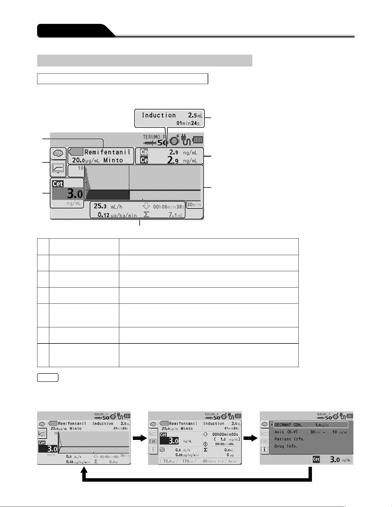
Screen Description
In the TCI mode
Graph screen
7
6
5
4
1
2
3
1 Drug display Displays the drug name with a colour tag, the drug concentration, and
the model.
2 Tab display Indicates the currently selected target (plasma or effect-site targeting)
and the type of TCI mode screen (graph, text, or info).
3 Target concentration
display
Displays the predicted concentration (Cpt or Cet) to be targeted.
4 Solution delivery
information display
Displays the current flow rate, dose rate, decrement (awakening) time,
and volume delivered.
5 Graph display Displays the change in a time lapse of the predicted concentration (Cp
or Ce) in a graphical format. The lines/areas are displayed in different
colours that are determined by the selected drug.
6 Cp/Ce display Displays the current value of Cp (predicted plasma concentration) and
Ce (predicted effect-site concentration).
7 Initial infusion display Displays the initial infusion dose and the time required before the target
concentration (Cpt or Cet) level is reached. (Available before the initial
infusion is started.)
Notes
Each time you press the Display select switch, the screen changes as shown below.
The display returns to the graph screen after 10 seconds of no operation on the Info screen.
Graph screen Text screen Info screen
9
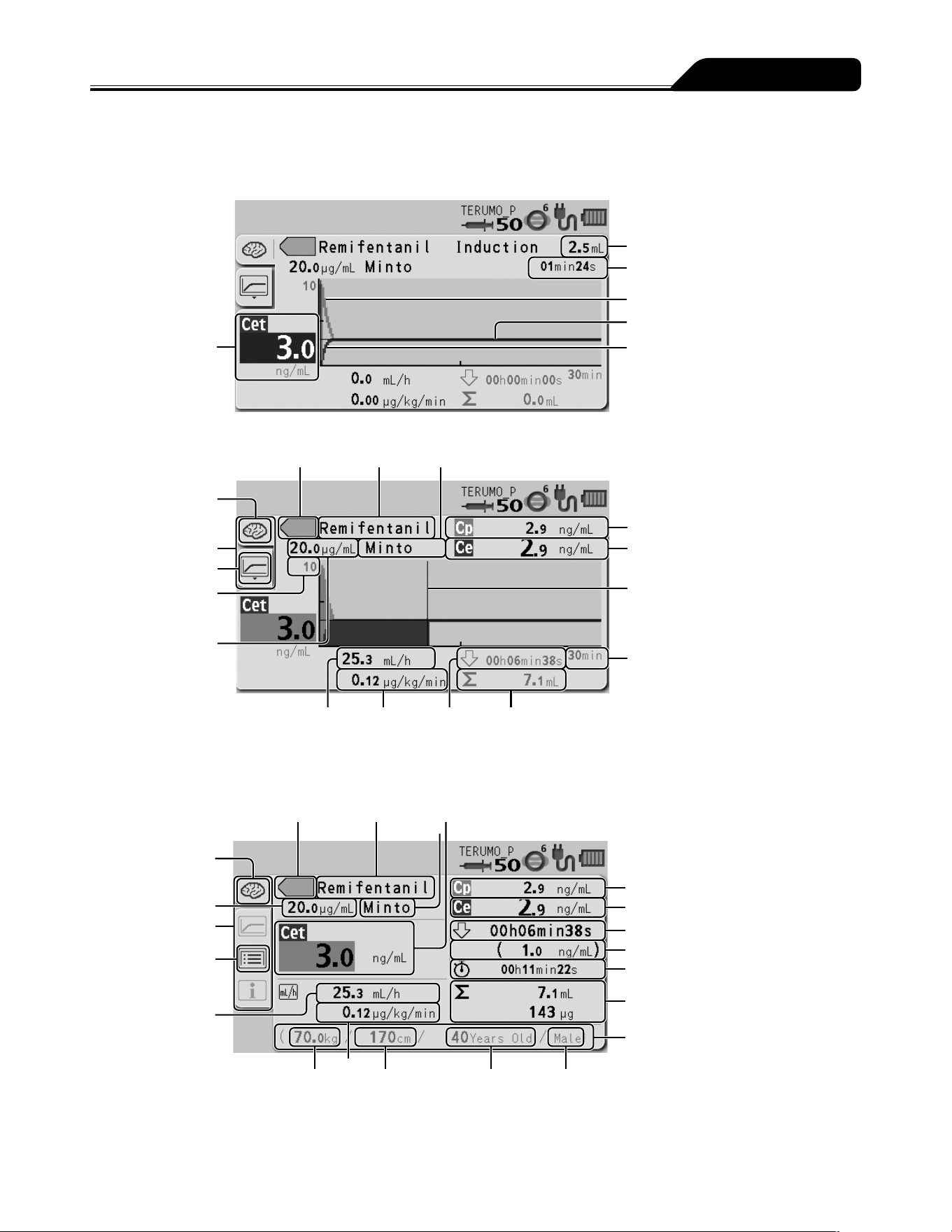
Parts Description
Graph screen (detailed)
Target concentration
(Cpt or Cet)
Initial infusion dose
Initial infusion time
Predicted plasma concentration
Target concentration (Cpt or Cet)
Predicted effect-site concentration
Before starting solution delivery
Model
Target tab
Predicted plasma concentration (Cp)
Predicted effect-site
concentration (Ce)
Unit of X axis (time)
Decrement
(awakening)
time
Volume delivered
Dose rateFlow rate
Drug concentration
Graph tab
Tab display
Unit of Y axis
(plasma/effect-site
concentration)
Actual time
During solution delivery
Colour tag Drug name Model
Text screen
Predicted plasma
concentration (Cp)
Predicted effect-site concentration (Ce)
Volume delivered
Gender
Age
Height
Dose rate
Flow rate
Text tab
Tab display
Target concentration (Cpt or Cet)
Drug concentration
Colour tag Drug name
Decrement (awakening) time
Decrement (awakening) concentration
Elapsed time
Patient information
Weight
Target tab
Model
10
Parts Description
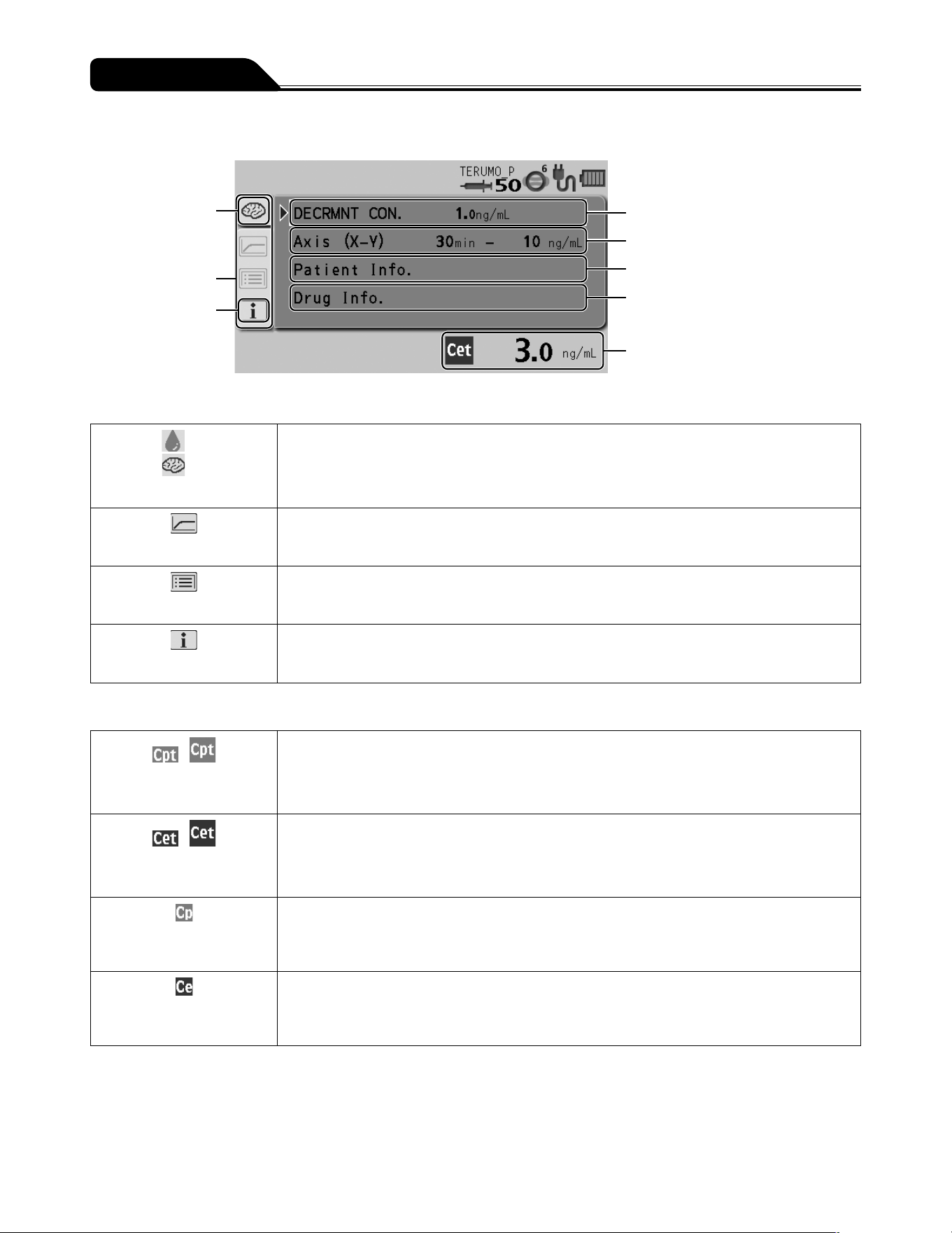
Info screen
Target tab
Graph axis
Target concentration (Cpt or Cet)
Info tab
Tab display
Decrement (awakening) concentration
Drug information
Patient information
Tab display
Cp
Ce
Target tab
Cp: Indicates the plasma targeted TCI mode is currently selected.
Ce: Indicates the effect-site targeted TCI mode is currently selected.
Graph tab
Displays the graph screen.
Text tab
Displays the text screen.
Info tab
Displays patient and drug information, and the target concentration (Cpt or Cet). Used when
setting the decrement (awakening) concentration and graph axis.
Concentration icon
/
Target plasma
concentration icon
Displays the target plasma concentration (Cpt).
/
Target effect-site
concentration icon
Displays the target effect-site concentration (Cet).
Predicted plasma
concentration icon
Displays the predicted plasma concentration (Cp).
Predicted effect-site
concentration icon
Displays the predicted effect-site concentration (Ce).
* See page 12 for the icons other than those listed above.
11
Parts Description
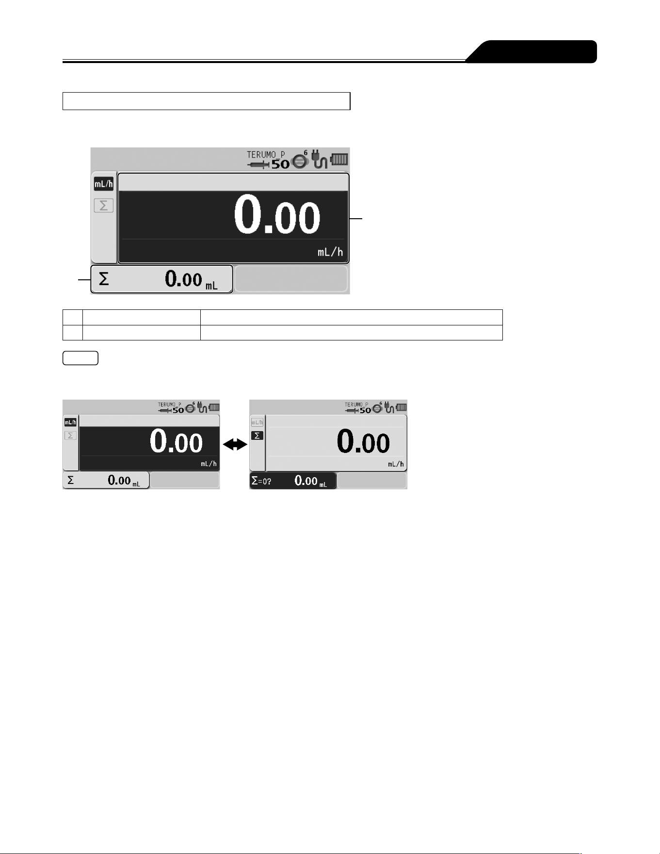
In other dose modes
Flow rate screen
2
1
1 Flow rate display Displays the value and information for the flow rate (mL/h), etc.
2 Volume delivered display Displays the volume delivered.
Notes
Each time you press the Display select switch, the selected items rotate as shown below. Selected item turns dark blue.
If not operated for 10 seconds, the input area moves to the flow rate display.
12
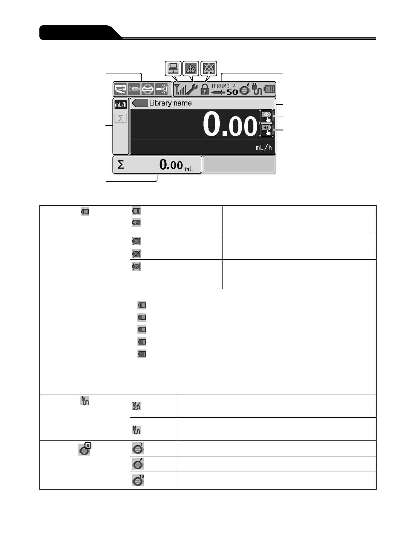
Parts Description
Sensor icon display
Tab display
Volume delivered display
Status icon display
Flow rate display
Start up icon
Ready for bolus icon
Status icon display
Battery icon
Displays the remaining battery
level.
(lit)
When AC power is connected and charge is full.
and the remaining battery
level flashing alternately
When AC power is connected and battery is charging.
(flashing every other second)
Battery failure
(flashing every half second)
Battery and sub-battery* failure
and the remaining battery
level flashing alternately every
other second
Sub-battery failure or low battery
Battery charge level (displayed in 5 bars)
5 bars (green): Approx. 8 hours
4 bars (green): Approx. 6 hours
3 bars (green): Approx. 4.5 hours
2 bars (green): Approx. 3 hours
1 bar (orange): Approx. 30 min (when the Battery alarm has not been issued)
(In the case of a continuous solution delivery at a flow rate of 5 mL/h at temperature of 25°C,
with new battery after charging for 8 hours or more with the power turned off.)
The battery can be charged to approx. 80% in 3 hours.
* The sub-battery is used for a Power Failure alarm.
AC icon
Displays connection/
disconnection of the AC power
supply.
When AC power is not connected
When AC power is connected
Occlusion icon
The occlusion detection pressure
is displayed in 10 levels (1 to 10)
in the upper right of the icon.
The occlusion detection pressure level is 1.
The occlusion detection pressure level is 6 (Default).
The occlusion detection pressure level is 10.
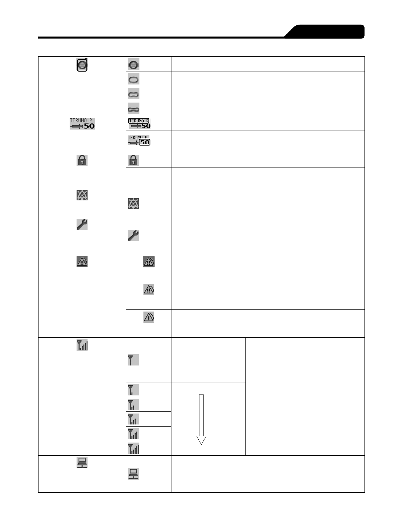
13
Parts Description
Occlusion icon
The internal pressure level of the
infusion line that does not reach
the level of Occlusion alarm is
displayed in 4 levels.
(grey)
Below 25% of the specified occlusion detection pressure.
(green)
25% or more of the specified occlusion detection pressure.
(yellow)
50% or more of the specified occlusion detection pressure.
(orange)
75% or more of the specified occlusion detection pressure.
Syringe brand/Syringe size
icon
Syringe brand
Syringe size to be used (5, 10, 20, 30, 50)
(If a syringe has not been set or has not been correctly detected, the size
display indicates --. )
Keypad lock icon
Displays when the keypad lock is
enabled (ON).
When the keypad lock is enabled (ON).
(No indicator) When the keypad lock is disabled (OFF).
Mute icon
Displays when an alarm is muted.
Alarm is muted
Maintenance icon
Displays when the maintenance
timer set period has elapsed.
When the set time period has elapsed
For the setting method, contact TERUMO trained service technicians.
Alarm icon
Displays when an alarm sounds.
(Background
colour: red)
When a high priority alarm sounds.
(Background
colour: yellow)
When a medium priority alarm sounds.
(Background
colour: yellow)
When a low priority alarm sounds.
Wireless LAN icon
Displays the strength of the
signal.
Antenna only is flashing:
The wireless LAN module
is faulty.
Antenna only is lit:
Connection to the network
system is not established.
Antenna + signal strength bars light grey:
Connection to the network system is
established.
Antenna + signal strength bars light green:
During communication.
Signal condition: Poor
Signal condition: Strong
Communication icon
Displays during the infrared
communication (IrDA
®
).
During communication
14
Parts Description
Sensor icon display
Syringe Displacement icon
Displays when a syringe displacement is detected.
Nearly Empty icon
Displays when the syringe is detected to be nearly empty.
Occlusion icon
Displays when an occlusion is detected.
Slider Displacement icon
Displays when a plunger displacement or slider displacement is detected.
Note
Nearly Empty icon and Occlusion icon are displayed when Syringe Empty occurs. (See page 137.)
Tab display
* A selected item that can be entered is displayed in dark blue.
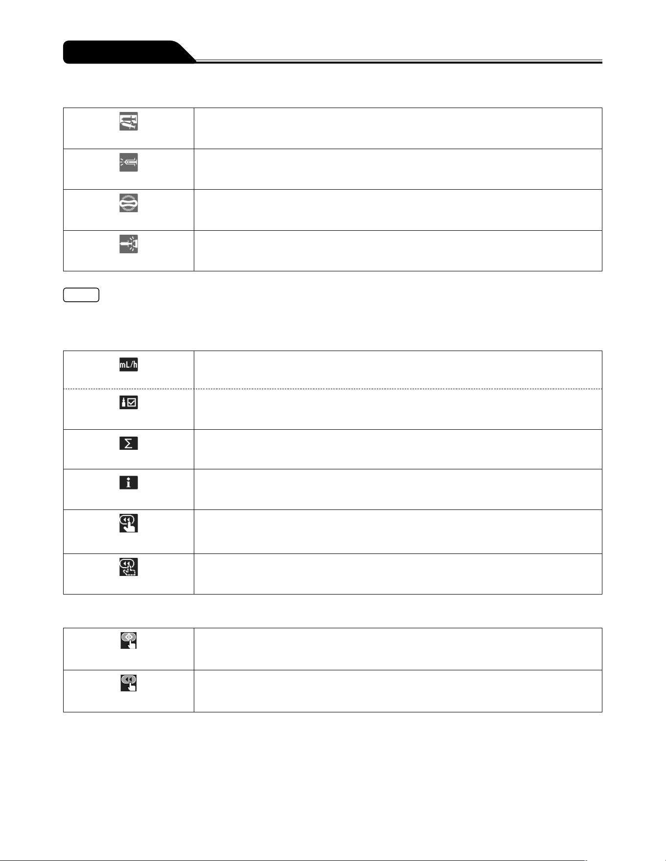
Flow rate tab
Used for setting the flow rate.
Dose rate tab
Used for setting the dose rate when the library or the weight mode is selected.
Volume delivery clear tab
Used for clearing volume delivery.
Info tab
Displays the setting information (unit, weight, drug amount, solution amount, etc.).
Hands On Bolus tab
Used for setting the Hands On Bolus function.
Hands Free Bolus tab
Used for setting the Hands Free Bolus function.
Ready icon
Start up icon
Displays when solution delivery is ready to start.
Ready for bolus icon
Displays when the pump is ready to start bolus.
15
Parts Description
Common screen
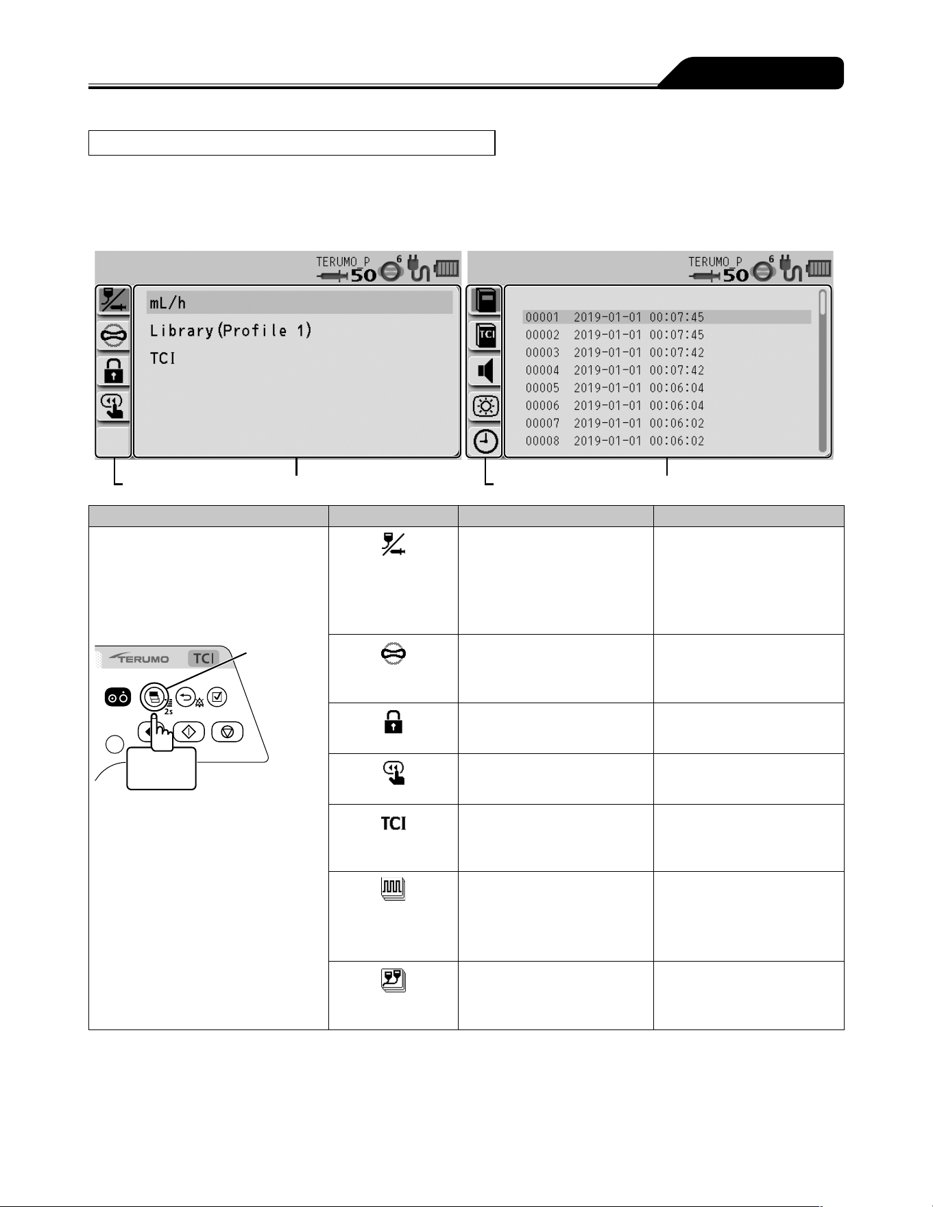
Menu screen
For the programming procedure, see page 79.
Menu 1 Menu 2
Menu tab Menu details display Menu tab Menu details display
Menu Menu tab Menu details Note
Menu 1
Press and hold the Display select
switch for 2 seconds or more.
This moves the input area to the
next item before displaying the menu
screen.
Display
select switch
2 seconds
or more
Dose mode select
mL/h
μg/kg/min
mg/kg/h
mg/kg/h+DIPRIVAN
Library
TCI
Other dose units can be
specified in the Drug Library.
Library is displayed after
uploading the Drug Library.
Occlusion
detection pressure
1 to 10
(± 10 kPa ↔ ± 120 kPa)
Sets the occlusion detection
pressure level.
Keypad lock
ON
OFF
Sets the keypad lock function
to ON or OFF.
Bolus
Hands On Bolus
Hands Free Bolus
Bolus infusion is available with
the Purge switch.
TCI
(TCI mode only)
Maximum flow rate
Plasma limit
Sets the upper limit of flow rate
and plasma concentration.
Advanced dose
mode
OFF
Interval/Intermittent Mode
Multi-step Mode
Delayed Start Mode
Selects an advanced dose
mode. (Displayed when a
drug library that allows for
advanced dose mode is
selected.)
Combination dose
mode
―
For details, contact TERUMO
trained service technicians.
16
Parts Description
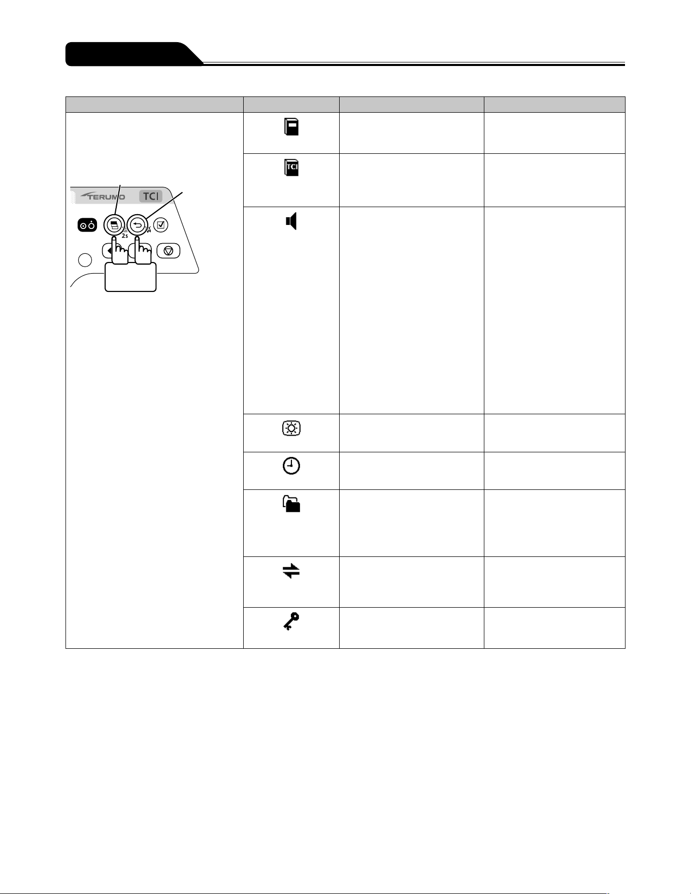
Menu Menu tab Menu details Note
Menu 2
While pressing the Back/Mute switch,
press and hold the Display select
switch for 2 seconds or more.
Display select switch
Back/Mute
switch
2 seconds
or more
History
Up to 10,000 events Checks the operation history.
TCI operation
history
Up to 5 events
Checks the TCI operation
history.
Sound volume
Alarm sound:
1: Low
2: Medium
3: High
Step: Step up
Operation sound:
0: Very low
1: Low
2: Medium
3: High
Cable insertion or extraction
sound:
0: Very low
1: Low
2: Medium
3: High
Sets the sound volume level.
Brightness
1 to 5
(Dark ↔ Bright)
Sets the brightness level.
Date and time
Year, Month, Day, Hour, Minute Sets the date and time.
Profile
Profile range can be set through
TERUFUSION Drug Library
Manager or TERUFUSION
Software Package (up to 30
profiles).
Selects the profile.
Communication
environment
Selection of Communication
environment table (up to 10)
Wireless LAN ON/OFF
Sets the communication
environment.
Password
If the password is set, some
special functions are password
protected.
Displays the menu only
available to TERUMO trained
service technicians.
17
Parts Description
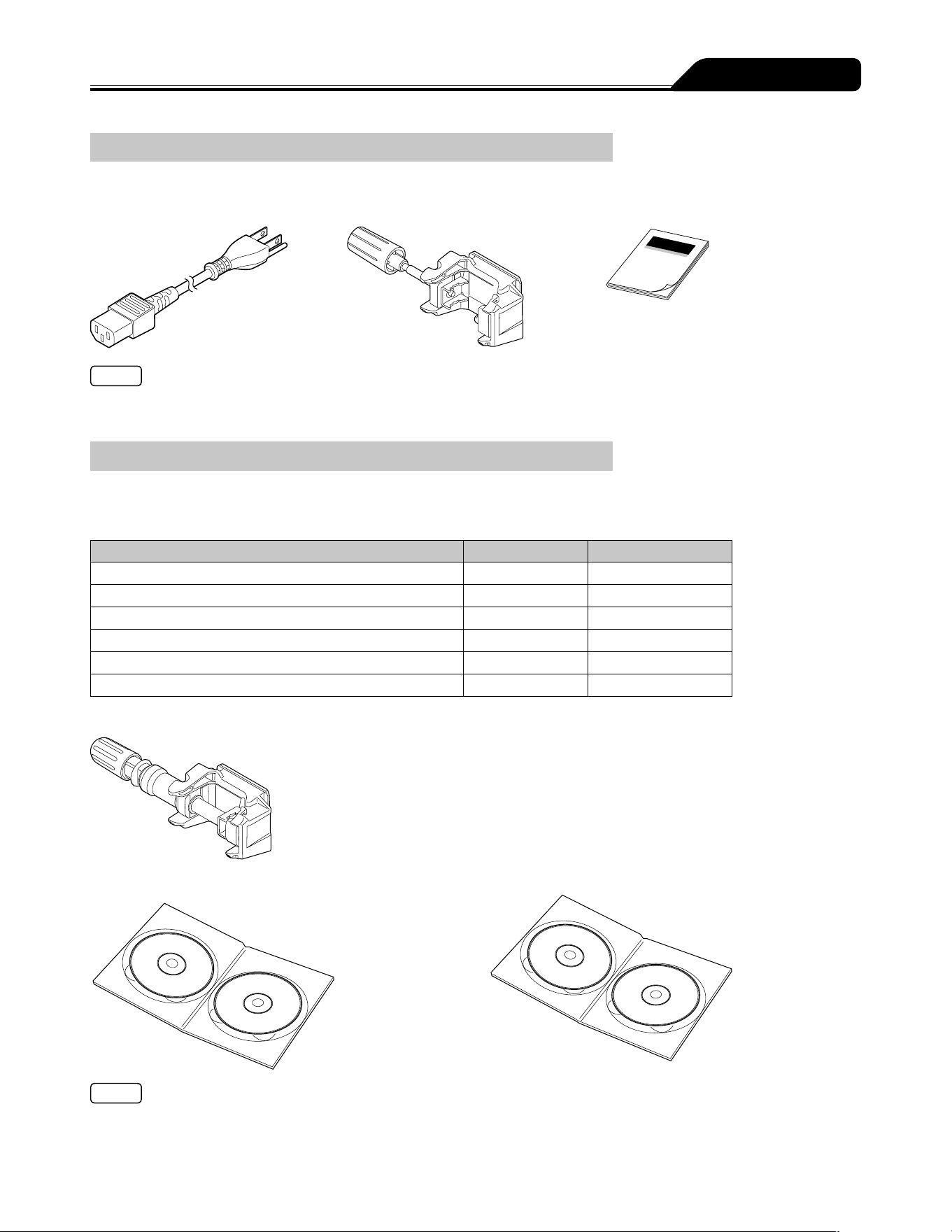
Standard Accessories
Standard accessories supplied with this product:
AC power cable
Pole clamp (Screw type) Instruction manual
Note
If an AC power cable is not included with the pump unit, please contact TERUMO trained service technicians to receive the cable
suited for your region.
Optional Accessories
Optional accessories are sold separately.
The specifications and external appearance of the product may be changed without notice for the purpose of improvement.
For details, see the instruction manuals supplied with each product.
Name Model Catalogue number
TERUFUSION One Touch Pole Clamp TE-877
TE
*
877
TERUFUSION Drug Library Manager TE-SW800
TE
*
SW800BE
TERUFUSION Software Package TE-SW800
TE
*
SW800PE
TERUFUSION Standard Rack System TE-RS700
TE
*
RS700N
TERUFUSION Communication Rack System TE-RS800
TE
*
RS800N
TERUFUSION Communication Rack System (Extension) TE-RS811
TE
*
RS811N
TERUFUSION One Touch Pole Clamp (TE-877)
TERUFUSION Drug Library Manager (TE-SW800) TERUFUSION Software Package (TE-SW800)
Note
When using the TERUFUSION Drug Library Manager or TERUFUSION Software Package, be sure to check the compatible with
that version of the pump you use. For the version, contact TERUMO trained service technicians. If the incorrect version is used,
some parts of the TERUFUSION Drug Library Manager or TERUFUSION Software Package are displayed abnormally.
18
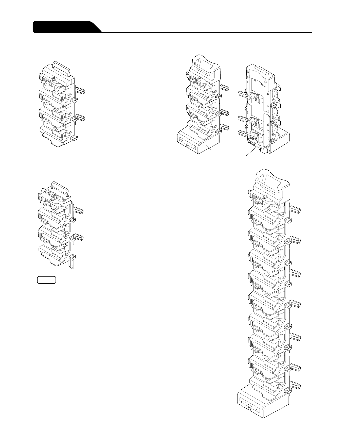
Parts Description
Rack system
TERUFUSION Standard Rack System (TE-RS700)
TERUFUSION Communication Rack System (TE-RS800)
Communication box
AC power box
TERUFUSION Communication Rack System
(Extension) (TE-RS811)
Notes
Up to three rack systems can be joined for use.
To join rack systems, contact TERUMO trained service
technicians.
<Combination Examples>
19
To ensure safe and correct use of this product, please observe all precautions.
Non-compliance with precautions and incorrect use may result in damage or injury.
The following are signs used in this manual and their meanings:
Warning
This label preceding a precaution indicates that there will be a possible risk of death or
personal injury if the precaution given is not complied with.
Caution
This label preceding a precaution indicates that there will be a possible risk of
personal injury or property damage if the precaution given is not complied with.
Use
Warnings
After the power is turned on, a syringe that corresponds to the syringe brand name displayed on the LCD should be used.
[The flow rate accuracy and alarm function cannot be guaranteed if a wrong syringe is used.]
Since TCI mode operation is based on plasma or effect-site concentration prediction, the user must observe the patients
condition, assuming there is always the possibility that actual concentration differs from the predicted values. If any
abnormality is found in the patients condition, immediately take appropriate measures such as manual dose or other
options for anesthesia. [Improper TCI infusion with predicted concentration mistaken as actual concentration may result in
critical harm to the patient.]
Always check the infusion status (decreasing volume of drug solution), connecting site and puncture site at the start of the
infusion. In addition, conduct the same check during infusion on a regular basis, including patient rounds.
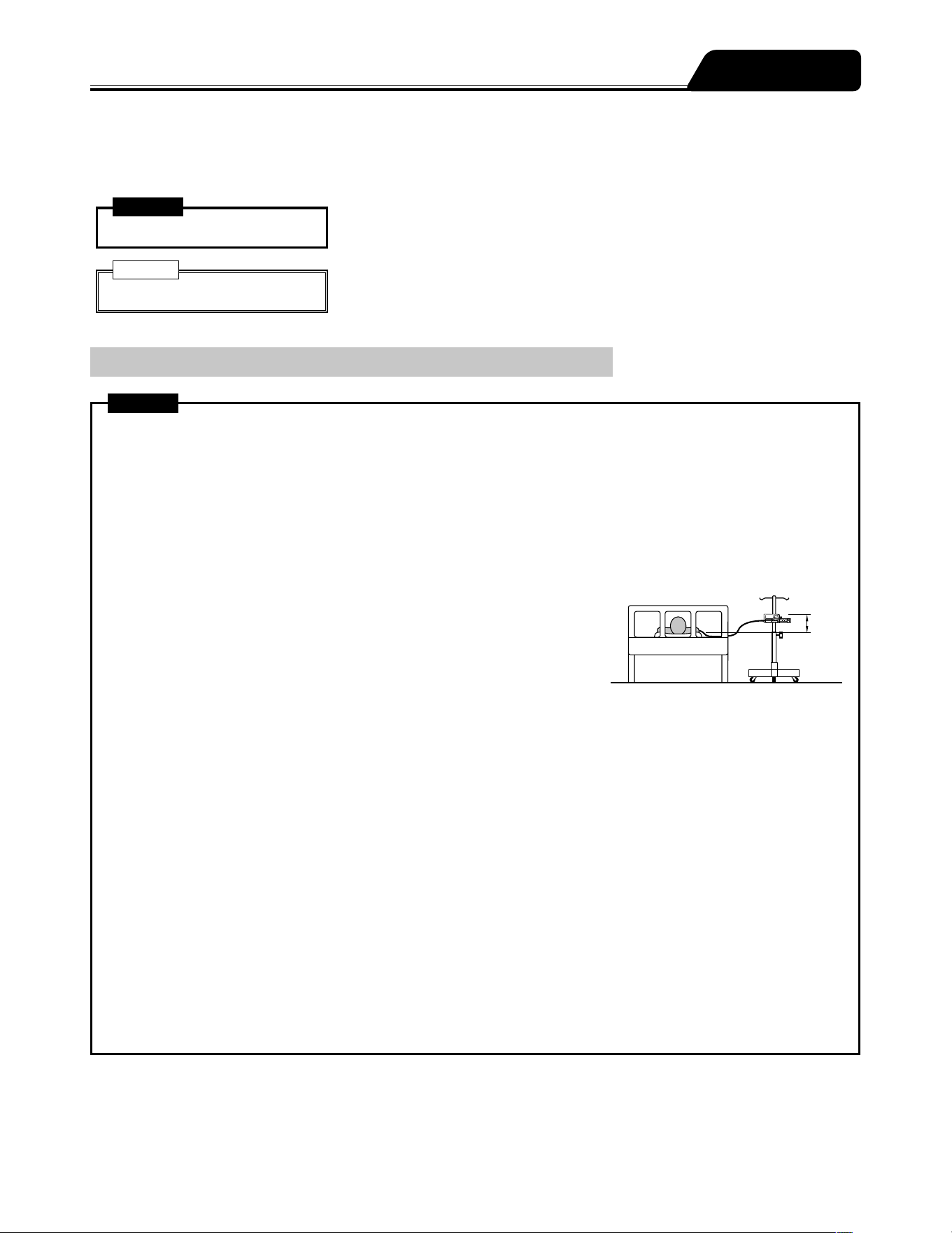
When setting a syringe, ensure that the syringe plunger has been firmly set
onto the slider hook and that the syringe has been correctly set into the sections
including checking that the flange of the syringe has been inserted into the flange
holder. The elevation difference between this product and the patient should be
kept to a minimum. [Drug solution may not be delivered correctly due to rapid
infusion caused by displacement of the syringe plunger from the slider hook,
incorrect detection of the syringe size, etc.]
When an occlusion occurs due to tube bend in the infusion line, blocked filter, blood clot inside the needle or other
reasons, close the infusion line on the downstream side, and eliminate the cause of the occlusion before starting. [1. The
internal pressure of infusion line from the pump to the occluded section in the downstream is high. Simply removing the
cause of occlusion will result in bolus infusion (temporarily excessive infusion of drug solution) to the patient. 2. The pump
will not operate until occlusion is removed.]
Do not apply any pressure to the syringe plunger or slider. [The syringe plunger may be pushed, causing bolus infusion to
the patient.]
When removing the syringe installed in this product, the three way stopcock (if used) of the infusion line should be closed
before removing it. [It may result in excessive infusion (siphoning free flow by gravity) of drug solution.]
When using at a low flow rate or under a low temperature, monitor the solution delivery carefully to check for any
occurrence of occlusion. [The solution delivery may be interrupted for a period due to: 1. The flow rate setting decreases,
the time from occlusion occurrence to detection becomes longer. 2. The temperature decreases, it interferes with the
movement of the syringe (the sliding resistance of the plunger increases), frequently causing the Occlusion alarm to be
issued.]
When using this product in environments with high background noise levels, the alarm sound volume of this product should
be adjusted so that alarms can be heard. [Background sound pressure levels higher than the alarm sound volume may
drown out an alarm, resulting in health hazard to the patient.]
When using this product with one or more other products, or with a similar device, make sure of the optimum alarm
settings for all those devices. [Unintended alarm settings may result in health hazard to the patient.]
Smaller
difference
Precautions

20
Precautions
Warnings
When infusing in the TCI mode, the following must be observed:
Do not inject the same drug before starting solution delivery in the TCI mode.
After ending the TCI mode, do not inject to the same patient again in the TCI mode during the period that the drug is
assumed to remain in the patients body.
Do not inject the same drug from another route during solution delivery in the TCI mode.
Do not use the Purge switch to inject drugs to a patient.
Otherwise, the prediction of concentration will be affected since the value is determined based on the calculation of
discharge quantity from the syringe in the TCI mode.
Before using the TCI mode, make sure the correct drug name, model, target, and target concentration are displayed.
[Incorrect settings of drug name, model, target, and target concentration may cause significant health hazard to the
patient.]
Since this product does not have an airtight structure, it should not be used or stored in an active gas environment
(including sterilizer gas), nebulizer-sprayed environment, high-humidity environment, etc. It should not be submerged
into water. [If the electronic components inside the product are affected, there may be subsequent damage and time
degradation which will cause failure of this product.]
The product should not be used or stored in a flammable environment.
The product should not be used for an extracorporeal circuit etc. that may lead to an extreme negative or positive pressure.
[Solution delivery may not be carried out correctly or rapid infusion may occur due to displacement of the syringe gasket
from the plunger or displacement of the syringe plunger from the slider hook. In addition, solution delivery may not be
carried out correctly because of bolus infusion, back-flow, etc.]
This product should not be used in conjunction with gravity infusion. [1. If this product suffers a downstream occlusion
lower than the connection with the gravity infusion line, the Occlusion alarm will not operate. 2. If bubbles are entrained in
the downstream of the infusion line due to emptied gravity infusion line first, the normal infusion cannot be carried out.]
A syringe other than specified should not be used for this product. [If using a syringe other than those specified, the flow
rate accuracy and alarm functions cannot be guaranteed.]
Cautions
Do not turn off the power or end the TCI mode while the TCI mode is in use. [Otherwise, all important information on the
current TCI mode, such as the predicted concentration, will be erased.]
When you change any settings, make sure those new settings are effective. [The setting is not applied and the previously
set value is restored if no operations are performed during the process for a certain period of time.]
When using a syringe (specified sterile syringe for general use) for this product, ensure that the nominal capacity of the
syringe is not exceeded. [If exceeded, the accuracy of flow rate or the alarm function cannot be guaranteed.]
Use the AC power cable included and connect to an earthed AC power source. The AC power cable included should not
be used for other equipment. [Using an AC power cable other than the one specified may result in failure of this product. In
addition, if used without an earth connection, the electrical safety of this product is not guaranteed.]
Before inserting an intravenous needle or connecting an infusion line with the connecting site, always bleed the air inside
the infusion line by pressing the purge switch and ensure that the slider pushes the syringe plunger. [1. This product
may cause harm to a patient due to air injection, since it does not have a function to detect air in the infusion line. 2. This
product may not be able to deliver solution for a while after started if there is a gap between the syringe plunger and the
slider, or between the syringe flange and the flange holder (on the clamp side).]
When using the TCI mode, be sure to select carefully the appropriate model and target for patients based on the patient
characteristics (such as age, physical trait, and medical/physical conditions) and the latest clinical findings. [Incorrect
settings of model and target may cause significant health hazard to the patient.]
When performing effect-site TCI, it is recommended to set the optimal plasma concentration overshoot before starting.
[There may be the cases where excessive overshoot in plasma concentration adversely affects the patient, in particular,
elderly patients or patients with high blood pressure.]
Before starting solution delivery, check that the settings for any errors. (e.g. an error in the digit of flow rate etc.) [This
product does not have a function to determine the correct values, possibly resulting in excessive infusion or insufficient
infusion to a patient.]
If the product is used under conditions that do not meet those specified for the flow rate accuracy described in
"Specifications", such as a low flow rate or short dosing time, the solution delivery should be monitored with extra care.
[The flow rate accuracy cannot be guaranteed.]

21
Precautions
Cautions
Turn the power on before the syringe is inserted, and check that the LCD and operation indicator are flashing, and that the
buzzer sounds. [If the power is turned on when a syringe is installed, this product cannot operate a normal self-check (self-
diagnosis).]
When installing a syringe, pull forward the clamp and turn. Then, after the syringe is set, turn the clamp back to the
original position and gently push it to fix the syringe. In addition, the slider should be moved while holding the clutch. [Any
unreasonable operation or excess operation will cause failure of this product.]
When setting the plunger to the slider, ensure that there is no gap between the syringe plunger and slider. [If the plunger is
set and there is a gap, the air or drug solution may be sucked by the slider hook.]
After a syringe has been installed, do not apply any force such as pulling or pushing the infusion line. [Applying these
forces may result in displacing the syringe barrel from the predefined position, temporarily delivering or sucking the drug
solution.]
When starting solution delivery, check the volume delivered and then clear it as needed before use.
After an Occlusion alarm is issued, always eliminate the cause of occlusion before starting. [In order to correct the volume
of bolus at the time of handling occlusions, this product has functions to automatically reduce the pressure inside the
infusion line at the occurrence of the Occlusion alarm (pulling back the slider, subtraction from the volume delivered).
Therefore, if starting without removing the cause, the infusion may not be carried out correctly such as causing the drug
solution in the infusion line to flow back to the syringe, or a repetitive Occlusion alarm status.]
This product should be placed and used on a level and stable location. In addition, when using the IV pole, ensure that the
stand is stable and this product is securely fixed to it. [Dropping or falling may result in damage or failure.]
When fixing this product to the IV pole, the specified pole clamp should be used. [If a pole clamp that has not been
specified is used, the function cannot be guaranteed. It may cause failure or accident.]
When attaching a pole clamp to the pump, ensure that it is set securely. [Failure to do so may result in falling of the pump
or pole clamp.]
When a pole clamp is used, do not release it until you have checked that this product is securely fixed to the IV pole.
[Failure to do so may result in falling of this product due to the loosened pole clamp knob.]
Disconnect the AC power cable from this product to remove it from the AC power source. Do not place this product in an
area with obstacles that block the AC power cable from being disconnected.
No part of this product, including the infusion line, should be taken into or used in a control area for radiation devices/
MRI or inside a hyperbaric oxygen therapy room. If any part of this product is accidently brought into these environments,
immediately discontinue use. [This product is not designed to be used in these environments. Malfunction, damage or
degradation of this product may occur or it may lead to explosion.]
During solution delivery, at a low flow rate in particular, do not move this product up or down. [The internal pressure level of
the infusion line changes due to gravity, which may cause excessive infusion or back-flow.]
Since this product is precision equipment, it should not be used if it has received any impact (drop to floor, falling from
the IV pole, violent shock). [Even though no fault is observed in the product appearance, the original functionality or
performance (flow rate accuracy and various alarm functions, etc.) of this product may not be achieved, and therefore
inspection is required.]
When purging a drug solution with high viscosity through a thin intravenous needle, an Occlusion alarm is likely to be
issued even if the infusion line is not occluded. A solution with high viscosity, deliver it at the rate of 100 mL/h or lower, not
by purging it. [If purging is continued, an Occlusion alarm may frequently be issued or the solution may be unable to be
delivered.]
Use the drug solution after it has adjusted to the room temperature. [If the drug solution is used when it is still cold, it
interferes with the movement of the syringe (causing resistance of the plunger), frequently causing the Occlusion alarm to
be issued.]
Use this product at the level of the patients heart in a range of ±130 cm.
When using this product together with other infusion systems, note that the alarm functions can be activated by one of
those systems.
Since drug solution may cause a short circuit, ensure that the connecting sections of the AC inlet and AC power cable are
not wet when connecting. If moisture is present, ensure that the power is turned off and the AC power cable is removed
from both the pump and earthed AC power source, and then thoroughly wipe with a dry cloth. [Since this product does not
have a waterproof structure, it may affect the electrical components inside, and cause a malfunction.]
Use an earthed AC power supply for normal use. The internal battery is an auxiliary power source for when the AC power
supply is not adequately available during transportation, power failure, etc.
Before use, check the manuals of the medical supplies and medical equipment that are used in combination.
This product should only be operated by skilled personnel.
22
Precautions
Cautions
Regular inspections should be conducted. If any fault is observed, stop using this product and request an inspection and
repair. [The original functionality or performance of this product may not be achieved.]
Attention is required not to apply any strong static electricity. [It may result in failure or malfunction.]
Prior to first use, or if unused for a long period, connect this product to an earthed AC power supply and provide a
sufficient charge (8 hours or more) with the power turned off. [If not sufficiently charged, this product may not be able to
operate using the internal battery during a power failure, etc.]
Even within the normal conditions of use, this product should not be used under conditions that cause a sudden
temperature change. [Condensation inside the product results in damage and time degradation, and therefore the original
functionality or performance of this product may not be achieved.]
The AC power cable used for this product should not be pinched with forceps or equipment, e.g. caster, or punctured with
a needle. [If a cable is damaged, electric shock or fire may occur. The original functionality or performance of this product
may not be achieved.]
This product should not be used in a place where vibration, dust, mist, corrosive gas, etc., occurs or in a place where
the product is sprayed with liquid. If solution is spilled on this product, thoroughly wipe with a dry soft cloth. [The original
functionality or performance of this product may not be achieved, and it may cause a malfunction.]
In a case where a manufacturer has made changes to their syringe, the flow rate accuracy and alarm function may not be
guaranteed. If any fault is observed, immediately stop using the product and contact TERUMO trained service technicians.
Avoid any location for placement that may cause interference with other infusion pumps.
When transporting with the pump fixed to the IV pole, do not hold the handle of the pump nor apply pressure from the top.
[The pole clamp may be dislocated or damaged.]
When this product is transported while in use, do not touch the switches, etc. Use the keypad lock function as needed.
[Touching the switches etc. without the keypad lock enabled may result in an operation (power on/off, stop, start, rapid
infusion) that is not intended by this product.]
The LCD and the Operation panel (switches etc.) of this product should not be pressed with excessive force and should not
be operated with a pointed object. [It may cause damage to or failure of the LCD or the Operation panel.]
Do not disassemble, make alterations (including actions that interfere with the functionality or performance such as
taping the LCD or a movable part) to, or repair this product. [This may result in failure, damage or device performance
degradation of this product.]
This product should only be used with a sufficient power supply. [If the power supply is not sufficient, the internal battery
will be used for the operation, which may result in no power supply in an emergency situation.]
When using devices (mobile phones, radio devices, radio knives, defibrillators, etc.) that emit an electromagnetic wave
within the area of this product, they should be used as far away as possible and you should verify the normal operation of
this product in the configuration it is used. In addition, this product should use a power supply of a system isolated from
these devices and should obtain secure earth connection. [Malfunction in this product may result in critical harm to the
patient.]
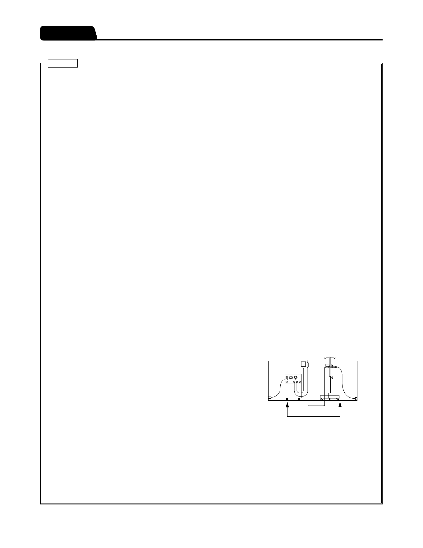
When used in the vicinity of a radio knife (Medical radio knives are surgical
equipment for incision and coagulation by high energy radiofrequency
current), check the following before use.
(1) Radio knives have a different level of high-frequency noise emission
depending on the types, and using old models (vacuum tube gap type)
in combination should be particularly avoided as the noise levels from
those are higher.
(2) The distance from the radio knife cord (knife holder, knife cord and
return electrode cord) and radio knife body to this product should be kept
to a minimum of 50 cm.
(3) The radio knife and this product should be operated by a power supply
from a separate system, and both should be securely earthed.
When connecting this product with other medical equipment or network system, check its conformance to IEC 60601-
1:2005+A1:2012 (EN 60601-1:2006+A1:2013), IEC 60601-1-2:2007 (EN 60601-1-2:2007) and IEC 60601-1-2:2014 (EN
60601-1-2:2015) prior to use in order to ensure the system safety.
When connecting this product with a network system or other equipment, for safety, checking the manufacturers
specifications of the equipment is recommended. In addition, use EMI compliant products for the connection cable.
When using the external communication function, pay particular attention, as it is more susceptible to the effect from a
radio knife, mobile phone, radio device, defibrillator, etc. Regularly check that this product is operating normally.
Medical
electrical
equipment
Power supply for
medical electrical
equipment
Keep 50 cm or more
Power supply from a different system
Power supply
for radio knife
Knife holder
Return electrode
Radio knife

23
Precautions
Cautions
When using the wireless LAN communication function, the effect on other equipment by radio interference should be
considered. [It may affect other equipment.]
When connecting this product with a network, the settings of this product and the network system need to be compatible.
Contact a vendor specialist for the correct settings and allow only the system administrator to perform settings. [Failure
to connect with correct settings may result in interfering with the original functionality or performance of this product and
affecting the network system.]
Connection to a network including other devices may cause unpredicted and unacceptable risks for the patient, the user,
or a third person. Be sure to identify, analyze, evaluate, and control those risks.
Subsequent changes to the IT-network could introduce new risks and require additional analysis.
- Changes to the IT-network include:
(1) Changes in the IT-network configuration.
(2) Connection of additional items to the IT-network.
(3) Disconnecting items from the IT-network.
(4) Update of equipment connected to the IT-network.
(5) Upgrade of equipment connected to the IT-network.
When using the IV pole, follow the instructions for the IV pole.
24
Use a syringe specified below.
This pump accepts TERUMO syringes and other major syringe brands listed in the table below.
The range of syringe brand selection can be limited. Contact TERUMO trained service technicians.
Warning
Before setting a syringe, ensure the brand of the syringe to be used is the same as the one specified on the pump. If the
brands do not match, the flow rate accuracy and alarm functions can not be guaranteed.
Caution
Before using the syringe pump, ensure that the size dimension of the syringe is the same as listed below. If there is any
change in the syringe specification, the flow rate accuracy and alarm functions may not be guaranteed. If any fault is
observed, immediately stop using the product and contact TERUMO trained service technicians.
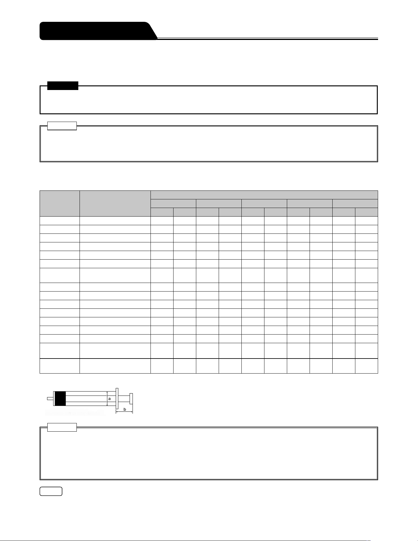
List of Compatible Syringe Brands
For your reference, these are the dimensions as measured in March 2012.
Hiển thị Nhãn hiệu
Cỡ bơm tiêm
5 mL 10 mL 20 mL 30 mL 50/60 mL
a [mm] b [mm] a [mm] b [mm] a [mm] b [mm] a [mm] b [mm] a [mm] b [mm]
TERUMO_J TERUMO JAPAN 15 14 17 18 22 19 26 23 32 24
TERUMO_P TERUMO PHILIPPINES 15 14 17 18 22 19 26 23 32 24
NIPRO NIPRO 15 14 17 18 22 19 26 23 32 24
ASPEN DIPRIVAN ― ― ― ― ― ― ― ― 30 17
BD_USA BD PLASTIPAK USA 14 14 17 13 22 16 24 17 30 17
B.BR_OMN B BRAUN OMNIFIX 14 17 18 16 22 16 24 17 31 20
B.BR_PER
B.BRAUN
ORIGINAL-PERFUSOR
― ― ― ― 21 16 ― ― 31 38
VACCINE*
1
VACCINE 14 17 17 16 22 19 24 20 32 21
P_FERTE PENTAFERTE 15 16 17 17 22 16 26 13 29 18
CHIRANA CHIRANA ― ― ― ― ― ― ― ― 30 21
CODAN CODAN 14 14 17 13 23 17 ― ― 30 20
CODAN_30 CODAN ― ― ― ― ― ― 23 17 ― ―
CODAN_PR CODAN PERFUSION ― ― ― ― ― ― ― ― 30 37
BD_PRECS BD PRECISE ― ― ― ― 23 21 ― ― 32 24
BD_PERFS
BD PLASTIPAK
PERFUSION
― ― ― ― ― ― ― ― 31 38
BD_IRELD
BD PLASTIPAK
IRELAND
― ― ― ― 21 16 24 16 30 16
*
1
50 mL: độ chính xác ± 5% ở tốc độ 1 mL/h
Size a : Approximate outer diameter of syringe
Size b : Approximate length from syringe flange to the end of the plunger when the
plunger is completely slid into the syringe.
Cautions
Only use specified syringes with luer lock for the pump.
TERUMO cannot accept any responsibility for errors in flow due to modifications of the syringe specifications introduced
by the manufacturer.
Differences in factors such as size and plunger force in compatible syringes may not fulfill flow rate accuracy of infusion.
Contact the syringe supplier for details on syringe specifications.
Note
When a custom syringe list is created by specifying a brand for each syringe size among the available syringes, it can be
registered to the pump to be available for use. Contact TERUMO trained service technicians.
Compatible Syringes
25
Prior to the initial use of the pump, set the date and time to record history correctly. (See page 110.)
Before use, carefully read Precautions and the labels attached to the product.
Prior to the Pump being Used
Connect to the AC power supply and charge (8 hours or more) with the power turned off.
Prior-to-use Inspection
Check the following points before use.
1) There is no damage to the main unit, AC power cable or pole clamp, and that there is no
malfunction due to adhered drug solution.
Main unit/AC power cable
1
2
2
43635
1. There is no damage, dent or adhered drug solution on the AC inlet and AC power cable.
2. There is no damage to the handle, rubber protector, tube holder and infrared communication window.
3. There is no damage or adhered drug solution on the slider, slider hook and flange holder (including Slit).
4. When moving the slider left and right with the clutch pushed, it should move smoothly, and when it is moved to the left
most position while the power is on, the Nearly Empty alarm should be issued. (See page 142.)
5. There is no adhered drug solution on the syringe clamp and that it moves back and forth smoothly.
6. There is no drug solution on the Dial, it turns smoothly, and flow rate setting can be set when the power is on.
If there is adhered drug solution, promptly clean in accordance with the directions on page 129.
Preparation
26
Preparation
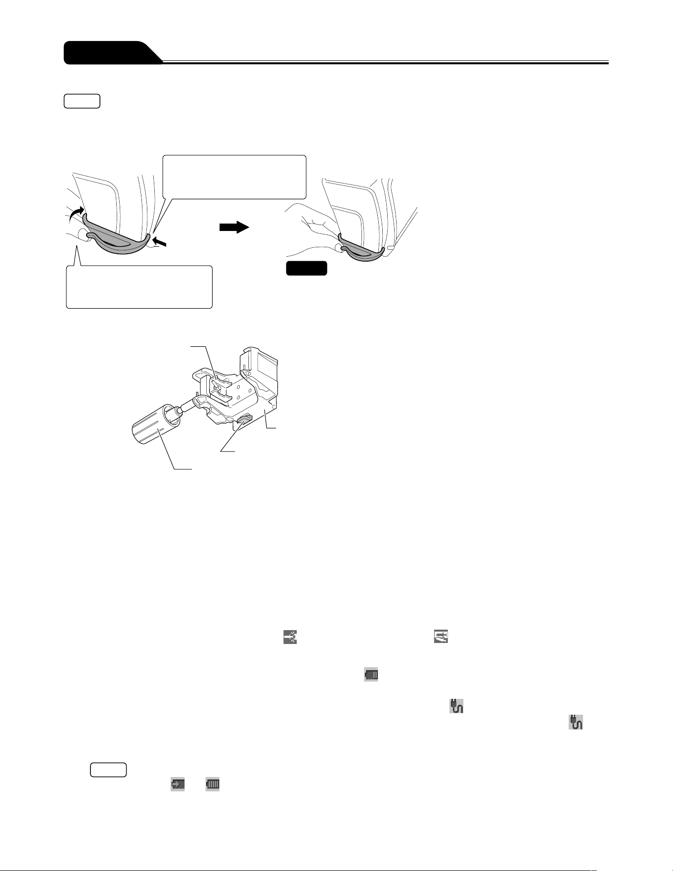
Notes
If the tube holder comes off, follow the procedure below to attach it.
When inserting the notch of the tube holder into the hole on the rear side, insert while pulling the tube holder towards the rear
side. Forcibly inserting into the hole may cause damage to the notch.
1) Insert the notch of the tube
holder into the front side
hole on the pump.
2) Insert the notch of the tube
holder into the rear side hole
on the pump.
The tube holder is firmly fixed to
the pump.
Check
Pole clamp
● Clamp portion of
the pole clamp
● Base portion of the pole clamp
● Pole clamp lock portion
● Pole clamp knob
1. There is no damage to any part of the pole clamp and that the clamp is clean.
2. When attaching pole clamp to the pump, it should lock in place firmly with an audible click.
3. There is no adhered drug solution on the pole clamp part and the clamp can be moved smoothly.
* If there is adhered drug solution, promptly clean in accordance with the directions on page 129.
Clean periodically even if there is no adhered drug solution.
2) The following self-check (self-diagnosis) operations should be performed when the power is
turned on using the internal battery without a syringe installed.
1. The operation indicator lights in green and red alternately.
2. The message Self-check is displayed on the LCD, and the LCD flashes.
3. The buzzer sounds.
4. The alarm icons, slider displacement icon
, and syringe displacement icon are flashing.
3) Neither Battery alarm or Power Failure alarm has been issued.
1. The level of the battery icon on the LCD has two bars (green) or more.
2. Neither Battery alarm (yellow) or Power Failure alarm (red) is displayed on the LCD.
4) When the AC power cable is connected, the LCD displays AC icon .
1. When the AC power cable is inserted into the AC inlet on the rear side of the main unit completely, the AC icon is
displayed.
2. If the internal battery is not fully charged, fully charge it.
Note
During charging, and flash alternately.
5) When the AC power cable is connected, there is no looseness or any fault.
The AC power cable is completely inserted into the AC inlet of the main unit.
27
Preparation
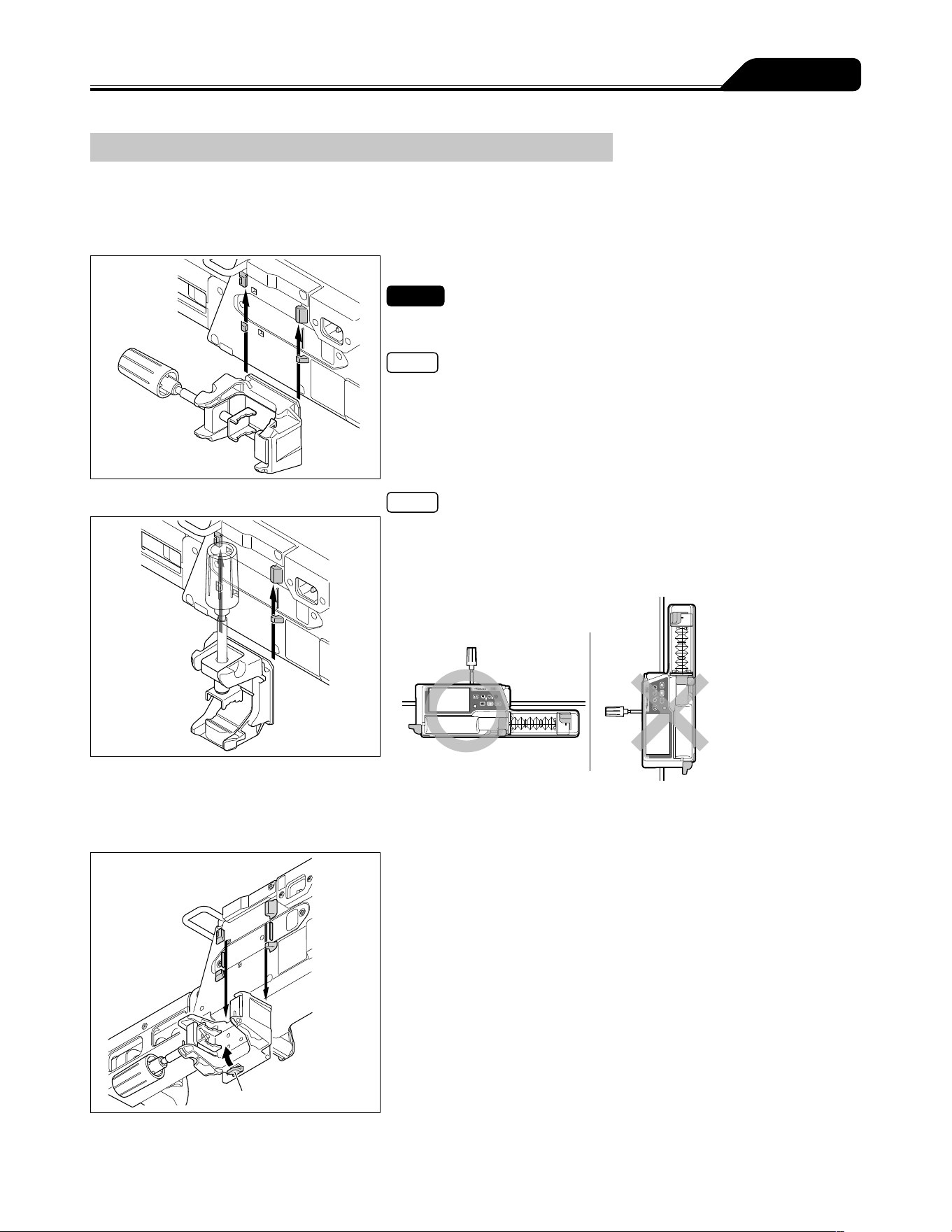
Attaching/Detaching a Pole Clamp
Attach the pole clamp
The pole clamp can be locked at the pole clamp lock portion only in the direction shown in the figures below.
To attach to a vertical pole
Insert the pole clamp along the grooves on the back of
the pump from the lower side.
Check
The pole clamp must be securely inserted. It should lock in place firmly with
an audible click.
Note
For instructions on attaching the IV pole and other parts, see page 28.
To attach to a horizontal pole
Notes
The pole clamp can be attached in the vertical direction as shown in the
figure. Note that the pump cannot be installed in the rack system when the
pole clamp is attached in the vertical direction.
Do not attach the pump in the vertical direction.
Detach the pole clamp
Pole clamp lock portion
Pull the pole clamp downward while pressing and
holding the pole clamp lock portion.
28
Preparation
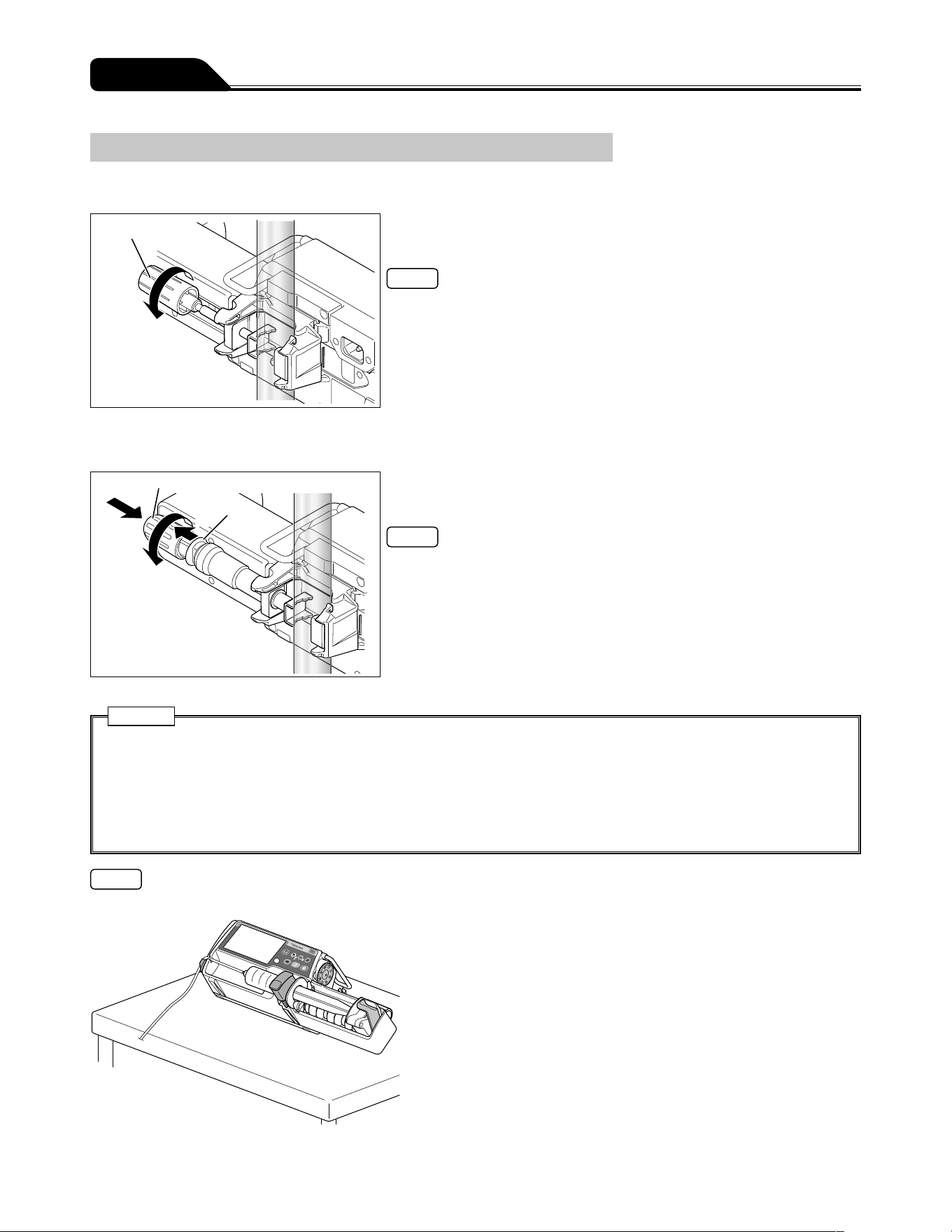
Attaching/Detaching to the IV Pole
Pole clamp (Screw type)
Pole clamp knob
Turn the pole clamp knob to fix the pump firmly to the IV
pole.
Note
When removing the pump from the IV Pole, hold the main unit and turn the
pole clamp knob opposite to the arrow shown in the figure.
TERUFUSION One Touch Pole Clamp (Optional accessory)
Pole clamp knob
Lever
(2)
(3)
(1)
Turn the pole clamp knob to fix the pump firmly to the IV
pole.
Notes
To attach the pole clamp quickly, before fixing it to the IV pole completely, pull
and hold the lever (1), push the knob in the direction of (2) and turn the knob
in the direction of (3) to fix the pump. (The lever cannot be pulled after the
pump is fixed to the pole).
To detach the pole clamp from the IV pole quickly, loosen it slightly by turning
the knob in the reverse direction of (3), pull and hold the lever (1), and pull the
knob in the reverse direction of (2).
Cautions
Make sure that pole clamp is firmly fixed to the IV pole and the IV pole is stable. When transporting with the unit fixed to
the IV pole, be aware as the pump may drop or fall due to a floor step, slope, contact with surrounding objects, etc.
When a pole clamp is used, do not release it until you have checked that this product is securely fixed to the IV pole.
Failure to do so may result in falling of this product due to the loosened pole clamp knob.
Do not turn the knob while the lever has been pulled. It may cause damage.
Do not pull the lever while it has been fixed to the IV pole. It may cause damage.
Note
The syringe pump can be set tilted with the pole clamp attached on a level and stable surface as shown below.
29
Preparation
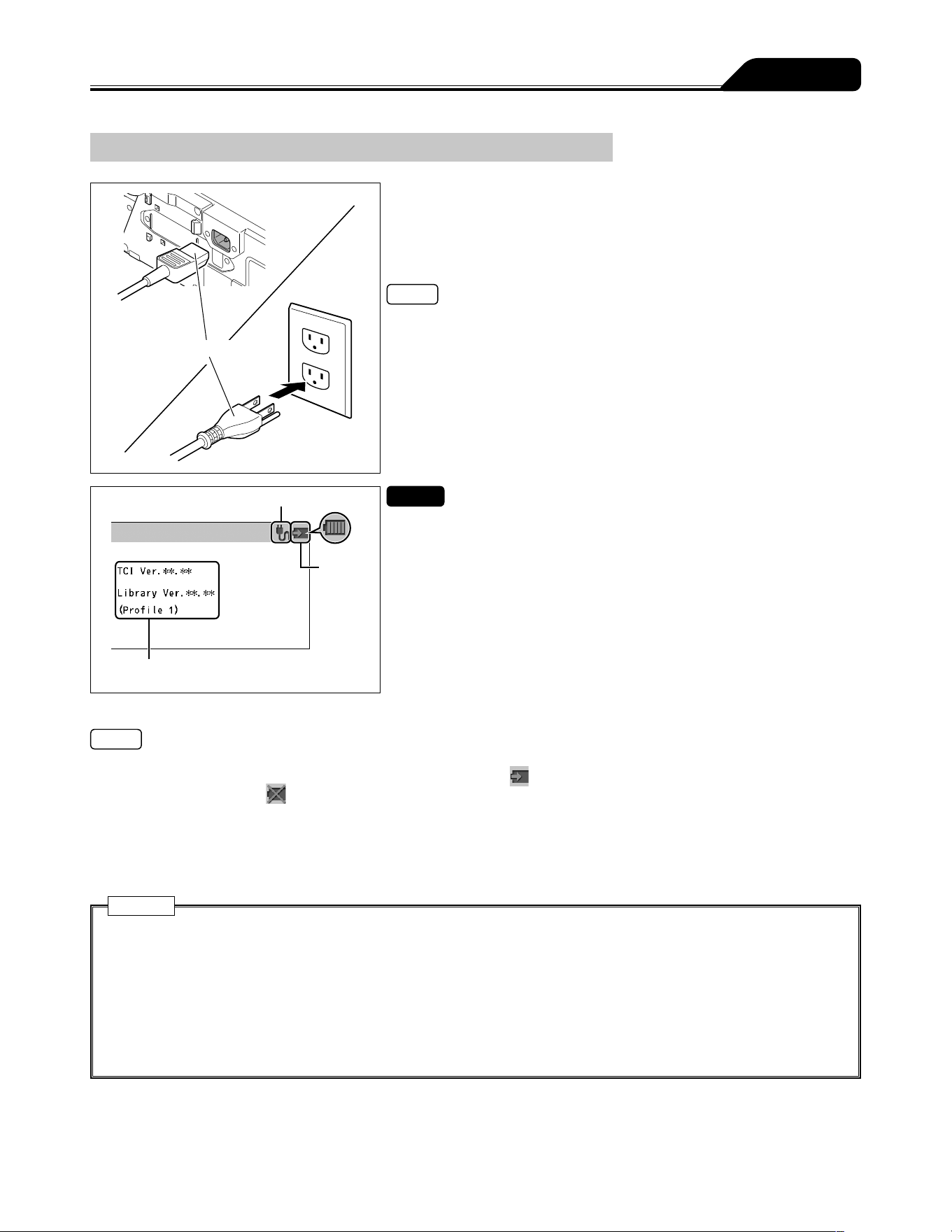
Connecting to AC Power
AC power cable
1) Firmly connect the AC power cable (included) to the AC
inlet.
2) Connect the plug to an AC power source with an earth
connection.
Note
If an AC power cable is not included with the pump unit, please contact
TERUMO trained service technicians to receive the cable suited for your
region.
AC icon
Battery
icon
Versions of drug library and TCI, and profile
name
Checks
The AC icon and battery icon should be displayed on the LCD.
The LCD should show the versions of the drug library and TCI, and the profile
name which is set by performing the procedure in Profile (page 112).
Notes
Even if the power is off, if the AC power has been supplied, the AC icon is displayed.
The battery can be charged even if the power is off. The battery icon
(charging) is displayed. There may be cases where the
remaining battery level and
(battery failure) flash alternately every other second when there is a sub-battery failure or low
battery.
If the AC power cable is disconnected or connected with power turned on, the buzzer sounds (Default setting: 0 (very low)). For
the changing sound volume, see page 105.
If the AC power cable is disconnected with power turned on, the LCD becomes dim (2 levels of brightness setting). When the AC
power cable is reconnected, the previous brightness is restored.
Cautions
Please ensure AC inlet and all connections are clean and dry prior to use. If moisture is present, make sure that the power
is turned off and the AC power cable is removed from both main unit and AC power source, and then thoroughly wipe with
a dry cloth.
Use the AC power cable included and connect to an earthed AC power source.
Use an earthed AC power supply for normal use. The internal battery is an auxiliary power source for when the AC power
supply is not adequately available during transportation, power failure, etc.
This product should only be used with a sufficient power supply. If the power supply is not sufficient, the internal battery
will be used for the operation, which may result in no power supply in an emergency situation.
30
Preparation
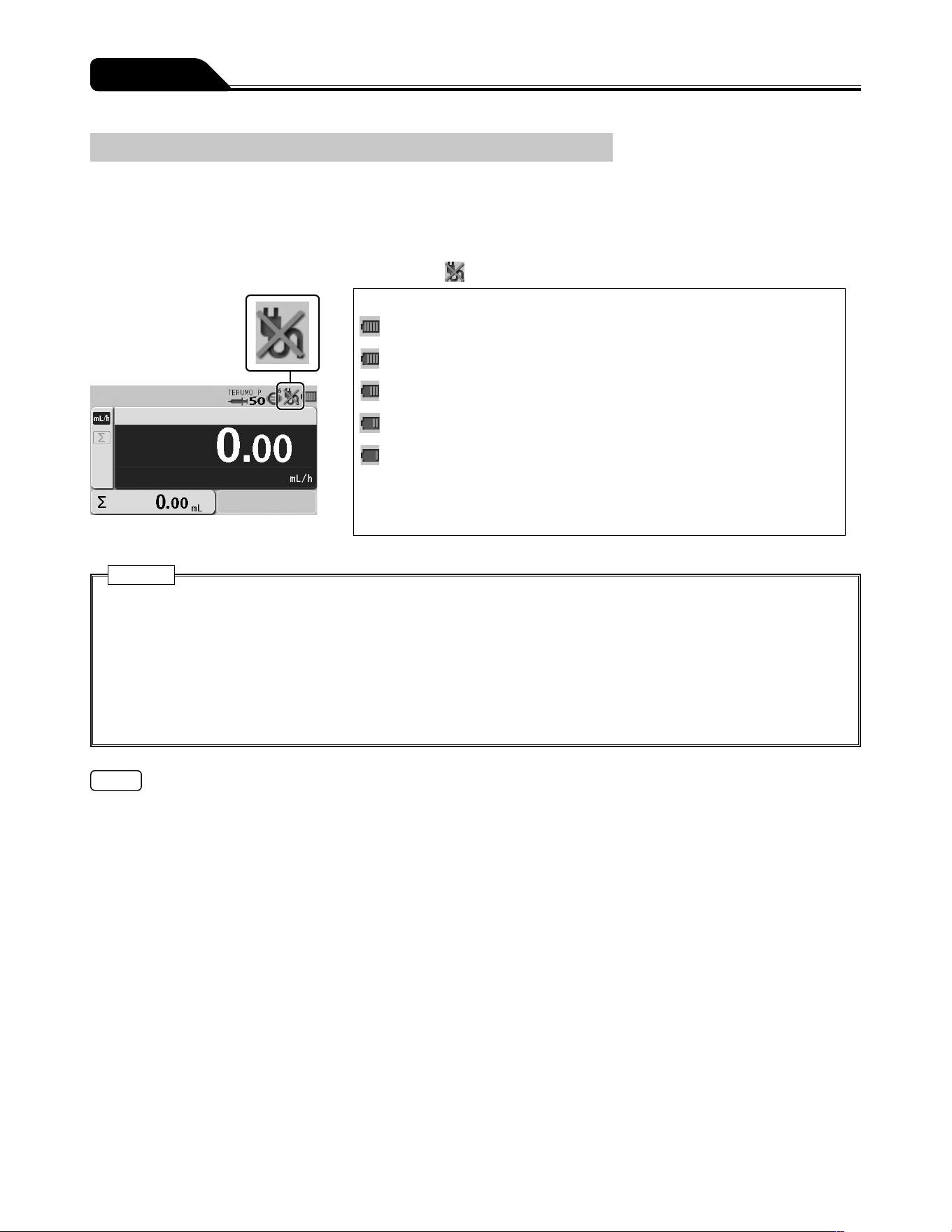
Operating by the Internal Battery
If the AC power supply is cut off, while in use or the power supply is reduced, the power supply is automatically switched to the
internal battery. The operation with internal battery is available for approx. 8 continuous hours. (In the case of continuous solution
delivery at a flow rate of 5 mL/h at temperature of 25°C, with new battery after charging for 8 hours or more with the power turned
off.)
When operating on the internal battery, the brightness of LCD backlight becomes two levels lower.
* In the case of no AC power, the LCD displays the AC icon
.
Battery charge level (displayed in 5 bars)
5 bars (green): Approx. 8 hours
4 bars (green): Approx. 6 hours
3 bars (green): Approx. 4.5 hours
2 bars (green): Approx. 3 hours
1 bar (orange): Approx. 30 min (when the Battery alarm has not been
issued)
(In the case of continuous solution delivery at a flow rate of 5 mL/h at
temperature of 25°C, with new battery after charging for 8 hours or more with the
power turned off.)
Cautions
Prior to first use after purchase, or if unused for a long period, connect this product to an AC power supply with an earth
connection and provide a sufficient charge (8 hours or more) while it is turned off. If not sufficiently charged, this product
may not be able to operate using the internal battery during a power failure, etc.
Time degradation of the internal battery will cause shorter operating hours than indicated by the battery icon on the LCD.
The battery should be replaced regularly approx. every 2.5 to 3 years (sub-battery: 1 to 2 years). (Since the flashing cross
on the battery icon indicates battery failure or replacement timing, use it as an indication for battery replacement.)
If any fault is observed while operating using the internal battery, immediately stop using the product and contact TERUMO
trained service technicians.
Notes
The operating hours of the internal battery are only an estimation. Since the actual operating hours may be shorter pay extra
attention to the status of the main unit when the internal battery is used.
When the battery charge level goes down, the Battery alarm sounds. Connect the AC cable immediately.
The alarm will continue to sound for approx. 30 minutes before the solution delivery is automatically stopped. (Even after muting,
the alarm will sound again every 2 minutes.)
If no action is taken for approx. 30 minutes after the Battery alarm sounds, the Shutdown Notice alarm will sound and the
solution delivery will be stopped. Then approx. 3 minutes later, the power is automatically turned off. (The Shutdown Notice
alarm will continue to alarm sound until the AC cable is connected. It cannot be muted by the Back/Mute switch.)
31
Operation Procedure
Using the TCI mode
Turning the Power On
Please ensure the product is fit for purpose prior to use.
The TCI mode is an alternative that enhances the convenience and control of intravenous anesthetic delivery.
The pump calculates and controls the flow rate to achieve and maintain the target concentration (Cpt or Cet). For details, see page
3.
Cautions
Conduct the self-check (self-diagnosis) of this product without a syringe installed. Otherwise the self-check may not be
conducted properly.
Check for any fault by conducting a self-check. If a fault is observed, immediately discontinue use and contact TERUMO
trained service technicians.
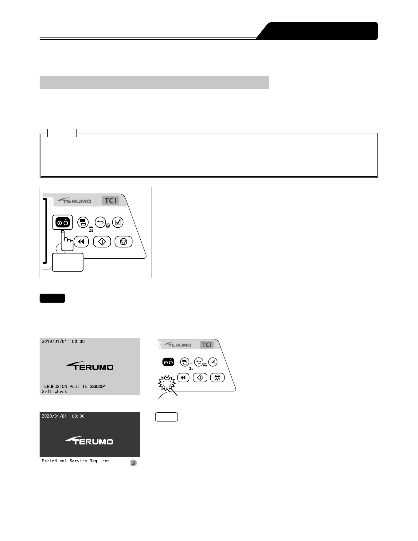
1 second
or more
Press and hold the Power switch for 1 second or more until
the TERUMO logo screen is displayed to turn the power on.
Checks
When turning the power on, the following occur simultaneously;
TERUMO logo appears on the display.
LCD flashes 3 times.
Operation indicator repeats lighting green and red alternately, and then buzzer sounds.
Operation indicator
Notes
A timer for maintenance can be set in this product. When the period set for the
maintenance timer is reached, a maintenance request is displayed at start up.
When the request is displayed, contact TERUMO trained service technicians.
When the period set for the maintenance timer is reached, this screen displays
at every start up until the setting is changed. For the setting method, contact
TERUMO trained service technicians.
32
Operation Procedure
Operation indicator
Checks
The syringe displacement icon
and
the slider displacement icon are
displayed flashing on the LCD.
The AC icon is displayed.
The battery icon is displayed, not
indicating the sub-battery failure.
The operation indicator is off.
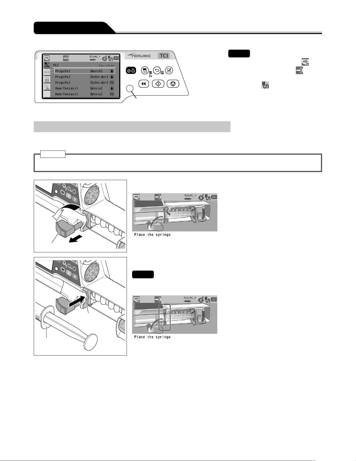
Setting the Syringe
1) Close the infusion line and attach a syringe filled with solution to it using aseptic technique.
Caution
Only use specified syringes with luer lock for the pump.
Clamp
1
2
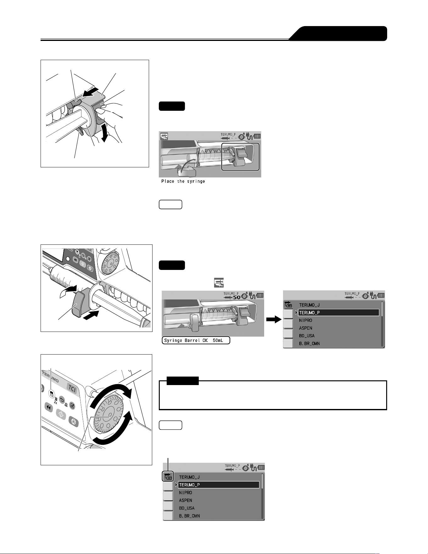
2) Pull the clamp forward and turn.
Flange
Slit
3) Insert the flange into the slit.
Checks
Check the LCD as shown below.
The flange of the syringe is correctly fitted into the slit.
33
Operation Procedure
Slider hook
Slider
Clutch
Plunger
Slider hook
4) While holding the clutch, move the slider until it meets the
plunger, and then release the clutch.
If the following guidance in the figure below does not
display, perform this step again.
Checks
The clutch appearing in the LCD should look as shown below.
The slider displacement icon is turned off.
Note
If the process is not completed after several attempts, the clutch may be ill fitting.
Ensure that the infusion line is not attached to a patient and then apply light
pressure to the slider to push the clutch into position.
The clutch may click when fitted into the position.
Clamp
2
1
5) Turn the clamp and gently push it to fix the syringe.
Check
The message Syringe Barrel OK xxx mL is displayed on the LCD, and the syringe
displacement icon
is not displayed. (xx is the size of the held syringe.)
Display select switch
Dial
6) Turn the Dial or press the Display select switch to select the
correct syringe brand.
Warning
After the syringe type is selected, recheck that the setting has been adjusted
correctly.
Notes
Turning the Dial or pressing the Display select switch moves the white frame.
The pump will automatically detect the syringe size.
Syringe brand tab
34
Operation Procedure
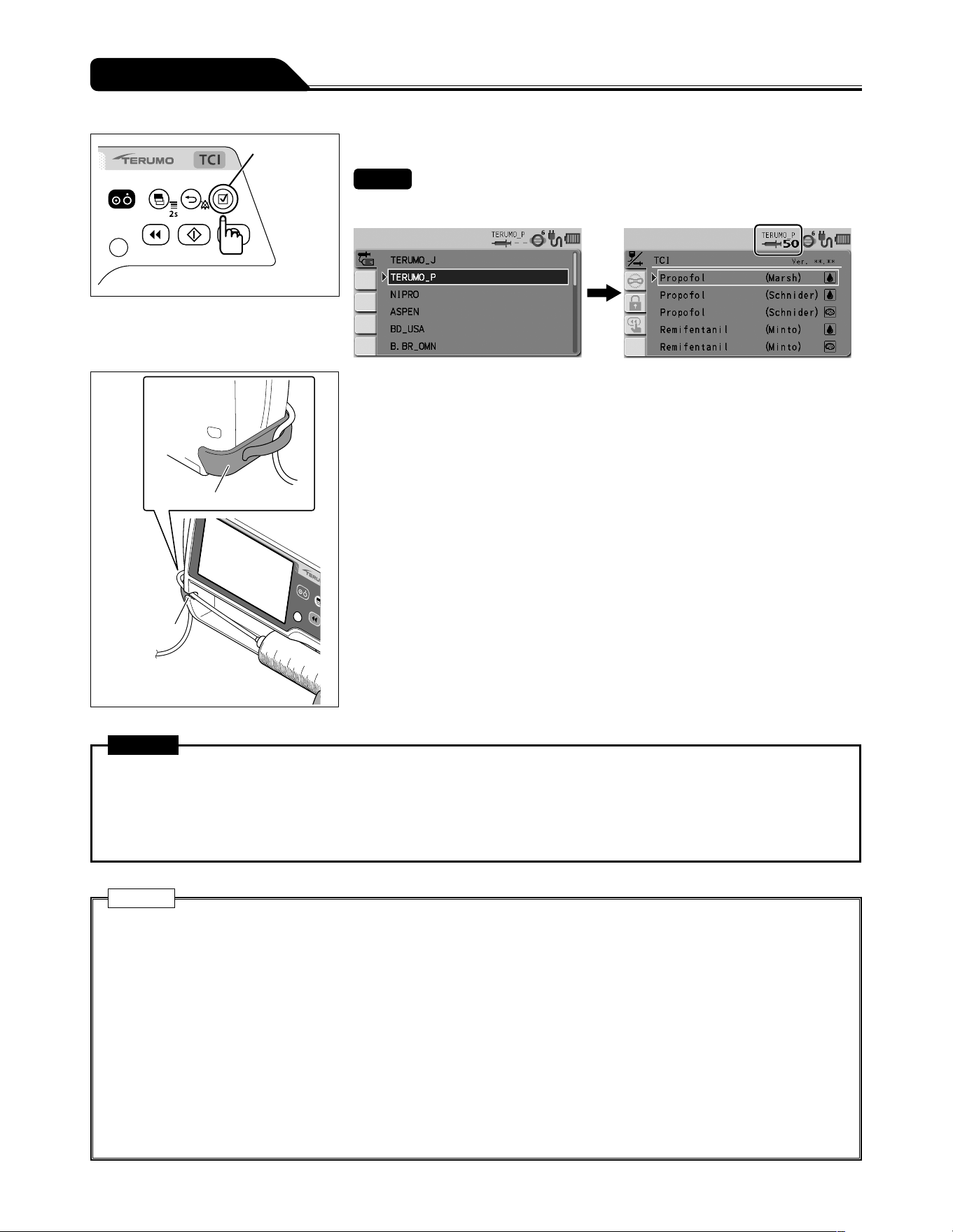
Confirmation
switch
7) Press the Confirmation switch.
Check
The syringe brand and the syringe size are displayed on the LCD correctly.
Tube holder
Tube guide
8) Insert the tube completely into the tube guide and set the
tube to the tube holder.
Warning
When setting a syringe, ensure that the syringe plunger has been firmly set onto the slider hook and that the syringe has
been correctly set and that the flange of the syringe has been inserted into the flange holder. The elevation difference
between this product and the patient should be kept to a minimum. Drug solution may not be delivered correctly due to
rapid infusion caused by displacement of the syringe plunger from the slider hook, incorrect detection of the syringe size,
etc.
Cautions
When setting a plunger into the slider, check that there is no gap between the plunger of the syringe and the slider. If the
plunger is set with gap between them, air or drug solution may be drawn in by the slider hook.
If the LCD displays the syringe displacement icon and the buzzer sounds, check the syringe has been set correctly, and
re-set if necessary. If the syringe is not installed at the correct position, the solution delivery cannot be started.
Even after the syringe is set in the proper position, if any fault is observed, immediately stop using the product and contact
TERUMO trained service technicians.
When installing a syringe, make sure that the syringe size and brand displayed on the LCD correspond to the syringe. If
they do not correspond with each other, it may cause unintended solution delivery.
When installing a syringe, pull forward the clamp and turn. Then, after the syringe is set, turn the clamp back to the
original position and gently push it to fix the syringe. In addition, the slider should be moved while holding the clutch. Any
unreasonable operation or excess operation will cause failure of this product.
When using a syringe (specified sterile syringe for general use) for this product, ensure that the nominal capacity of the
syringe is not exceeded. If exceeded, the accuracy of flow rate or the alarm function cannot be guaranteed.
35
Operation Procedure
Selecting the TCI mode
Select the desired TCI mode from five available combinations of drugs, models, and targets, then set the required patient
information (such as body weight) and the target concentration.
These settings enable the calculation of the initial infusion dose and the time required before the target concentration level is
reached.
The following shows an example when Remifentanil (Minto) for effect-site TCI is selected.
Display select switch
Dial
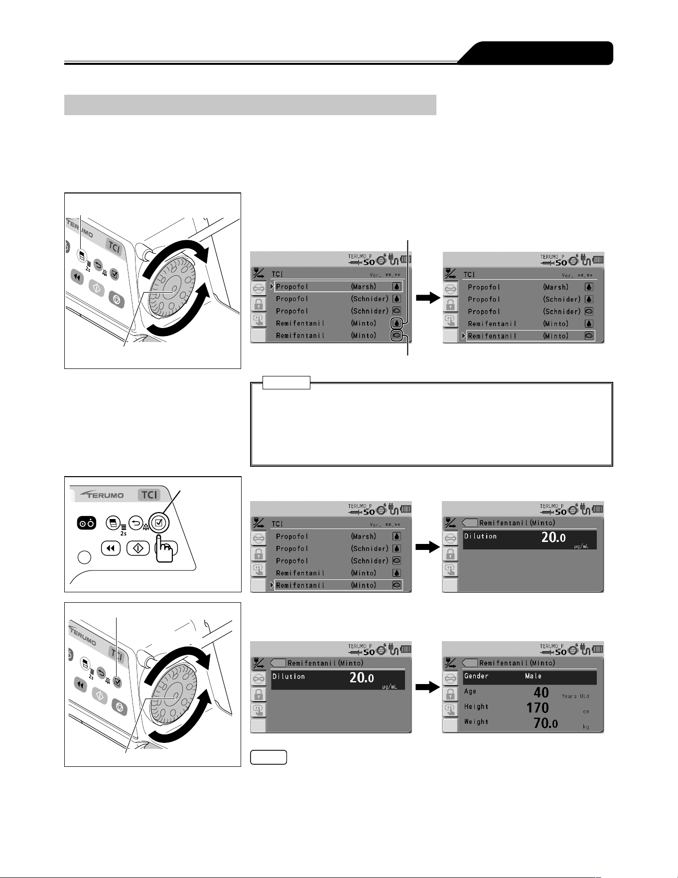
1) Turn the Dial or press the Display select switch to select the
desired TCI mode (drug name, model, and target).
Plasma targeting
Effect-site targeting
Caution
When using the TCI mode, be sure to select carefully the appropriate model
and target for patients based on the patient characteristics (such as age,
physical trait, and medical/physical conditions) and the latest clinical findings.
Incorrect settings of model and target may cause significant health hazard to
the patient.
Confirmation
switch
2) Press the Confirmation switch.
Confirmation switch
Increases value
Dial
Decreases
value
3) Turn the Dial to set the dilution, then press the Confirmation
switch.
Notes
The setting range for Dilution is 0.1 to 500.0.
The default setting for Dilution is 20.0 μg/mL.
When Propofol is selected, Dilution can be set to 1% (default) or 2%.
36
Operation Procedure
Confirmation switch
Increases value
Dial
Decreases
value
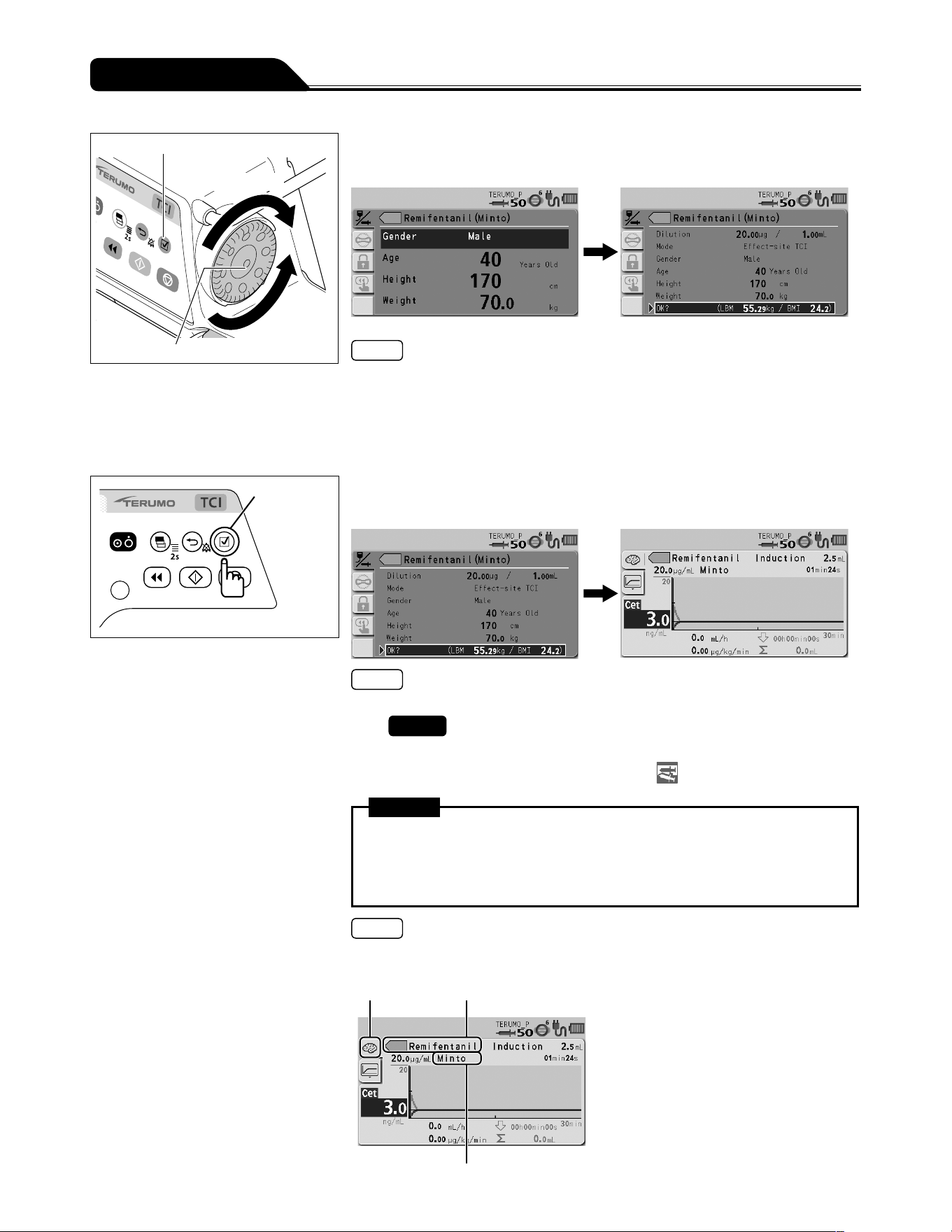
4) Turn the Dial to set the gender, age, height, and weight, then
press the Confirmation switch.
Notes
The setting range is as follows:
Age: 12 to 100 (Remifentanil), 16 to 100 (Propofol)
Height: 100 to 250 cm
Weight: 30.0 to 200.0 kg
The default setting is Male, 40 Years Old, 170 cm, and 70.0 kg.
When Propofol (Marsh) is selected, Gender and Height are not displayed.
Confirmation
switch
5) Check the parameter value and that OK? is selected, then
press the Confirmation switch.
Note
Cpt is displayed instead of Cet when plasma TCI is selected.
6)
Check
The selected drug name, model, and target are displayed,
and the syringe displacement icon
is not displayed.
Warning
Before using the TCI mode, make sure the correct drug name, model, target,
and target concentration are displayed. Incorrect settings of drug name,
model, target, and target concentration may cause significant health hazard to
the patient.
Note
The colour tag and the graph lines/areas are displayed in unique colours for each
drug, which makes it easier to identify the currently selected drug.
Target Drug name with colour tag
Model
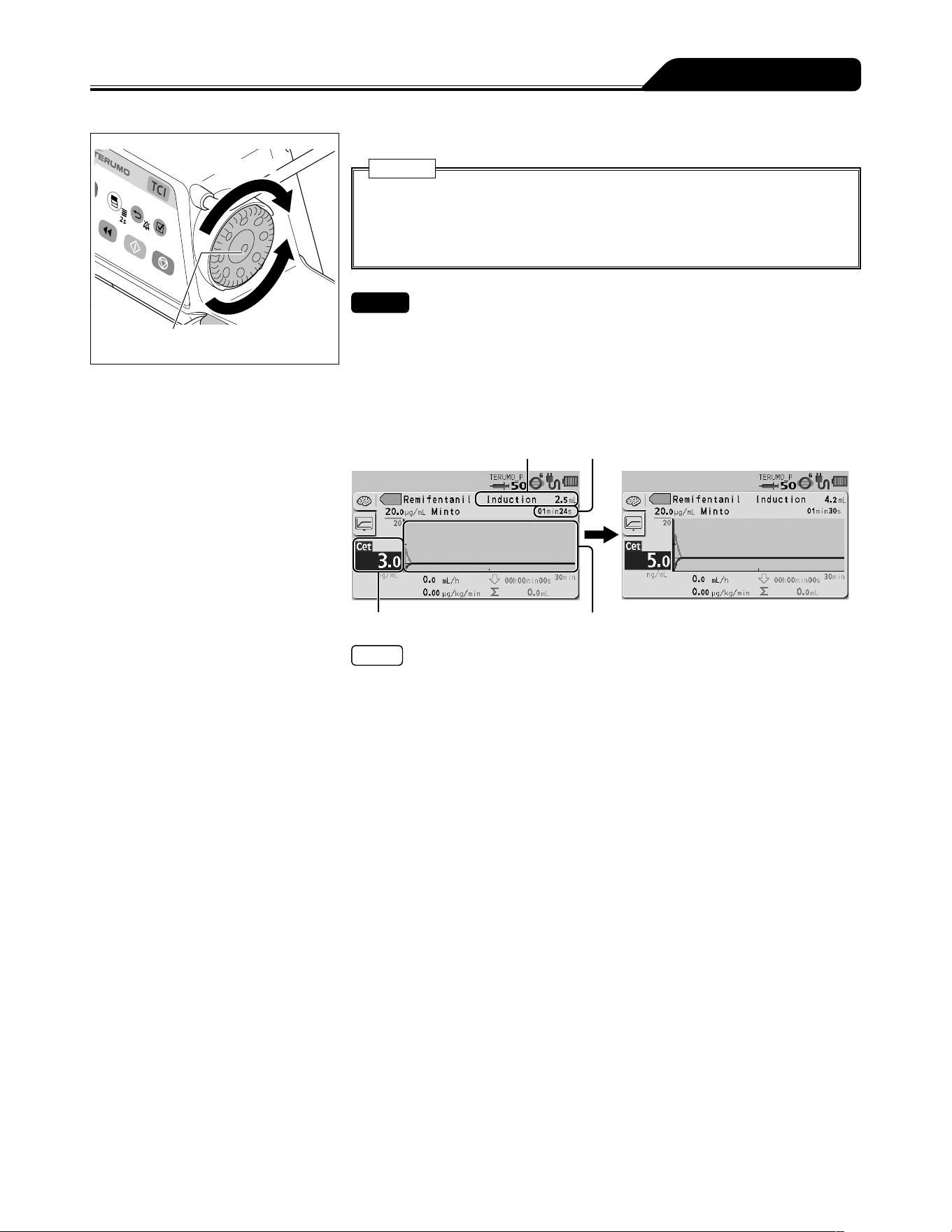
37
Operation Procedure
Increases value
Dial
Decreases
value
7) Turn the Dial to adjust the target concentration (Cpt or Cet).
Caution
When performing effect-site TCI, it is recommended to set the optimal plasma
concentration overshoot before starting. There may be the cases where
excessive overshoot in plasma concentration adversely affects the patient, in
particular, elderly patients or patients with high blood pressure.
Checks
The syringe pump is ready to start when the following are confirmed:
The initial infusion dose and time are displayed.
The Start Reminder message appears flashing in the lower section of the LCD.
The buzzer sounds every minute of no operation. After the first solution delivery
starts, the buzzer sounds every 30 seconds of no operation.
When the target concentration (Cpt or Cet) is 0.0, no message is displayed and no
buzzer sounds.
Initial infusion dose
Target concentration (Cpt or Cet)
Initial infusion time
Prediction lines
Notes
The target concentration (Cpt or Cet) can be set within the following range:
0.0 to 15.0 μg/mL in 0.1 μg/mL step (Propofol)
0.0 to 50.0 ng/mL in 0.1 ng/mL step (Remifentanil)
The default setting of the target concentration (Cpt or Cet) is 4.0 μg/mL (Propofol)
and 3.0 ng/mL (Remifentanil).
If the set value exceeds 10.0 μg/mL (Propofol) or 10.0 ng/mL (Remifentanil), the
message Soft upper limit reached, Override? is displayed.
When 15.0 μg/mL (Propofol) or 50.0 ng/mL (Remifentanil) is reached, the message
This is the hard upper limit is displayed on the LCD.
As the value of target concentration (Cpt or Cet) is changed, the initial infusion
dose/time and the prediction lines in the graph change accordingly.
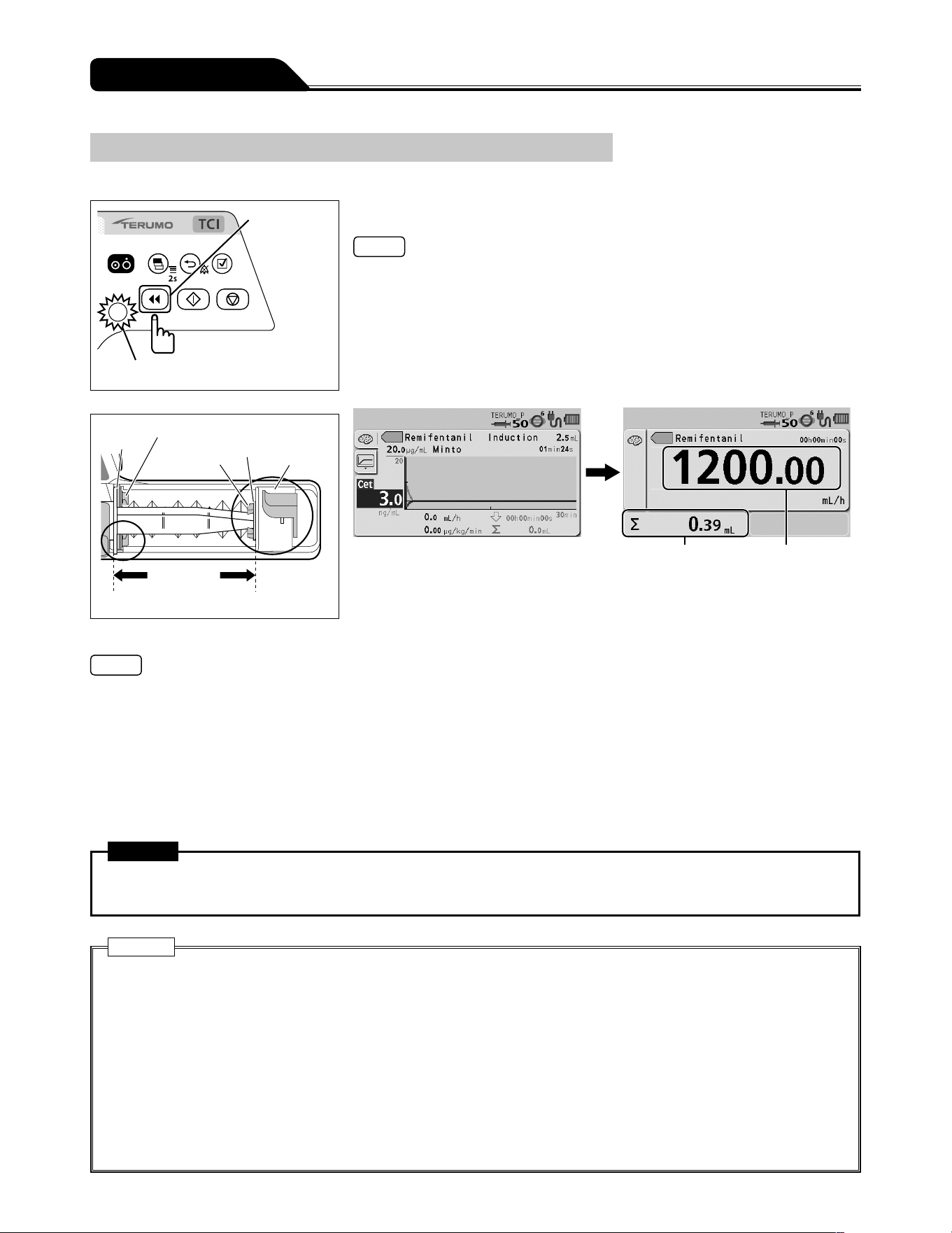
38
Operation Procedure
Priming
Before connecting the infusion line to the patient, perform priming to extract air from the line.
Purge switch
Operation indicator (green flashing)
Flange
Flange holder
Slider hook
Plunger
Slider
The syringe is
fit exactly.
Press and hold the Purge switch to perform priming.
Notes
During the priming operation, the buzzer sounds and the operation indicator
flashes green.
During the priming operation, the purge flow rate is displayed on the flow rate
display.
If any other switch is pressed while the Purge switch is pressed, the safety function
detects it as an abnormal operation and stops purging.
After the priming operation is finished, the screen transits to the graph screen.
Before starting solution delivery
Volume delivered Flow rate display
(purge flow rate)
During priming
Notes
The syringe size and the purge flow rate are as follows:
When using syringe of 5 mL: approx. 150 mL/h
When using syringe of 10 mL: approx. 300 mL/h
When using syringe of 20 mL: approx. 400 mL/h
When using syringe of 30 mL: approx. 500 mL/h
When using syringe of 50/60 mL: approx. 1200 mL/h
With the Purge switch pressed and held, the volume delivered display shows the volume purged.
The upper limit of purge volume is 2 mL.
The priming function will not work when the syringe pump is stopped by an alarm.
Warning
In the TCI mode, perform priming before inserting the intravenous needle to the patient. Otherwise, it may result in an
overdose.
Cautions
TCI mode cannot be used if the syringe is not set properly, since the contents of the syringe will not be recognised.
Before inserting an intravenous needle or connecting an infusion line with the connecting site, always prime the infusion
line by pressing the Purge switch. This product may cause harm to a patient due to air injection, since it does not have a
function to detect air in the infusion line.
Failure by any mechanical gap may cause considerable delay in the start of the infusion.
This is especially the case when a large syringe (e.g. 50 mL) is used at very low flow rate settings and/or when anti-siphon
valves are used in the infusion line.
Use the priming function to remove any mechanical gap: between the syringe plunger and the slider; between the flange
and the syringe pump slit.
When purging the solution, note that the volume purged is not added to the volume delivered. If this is not considered, the
volume delivered will differ from the actual infusion volume.
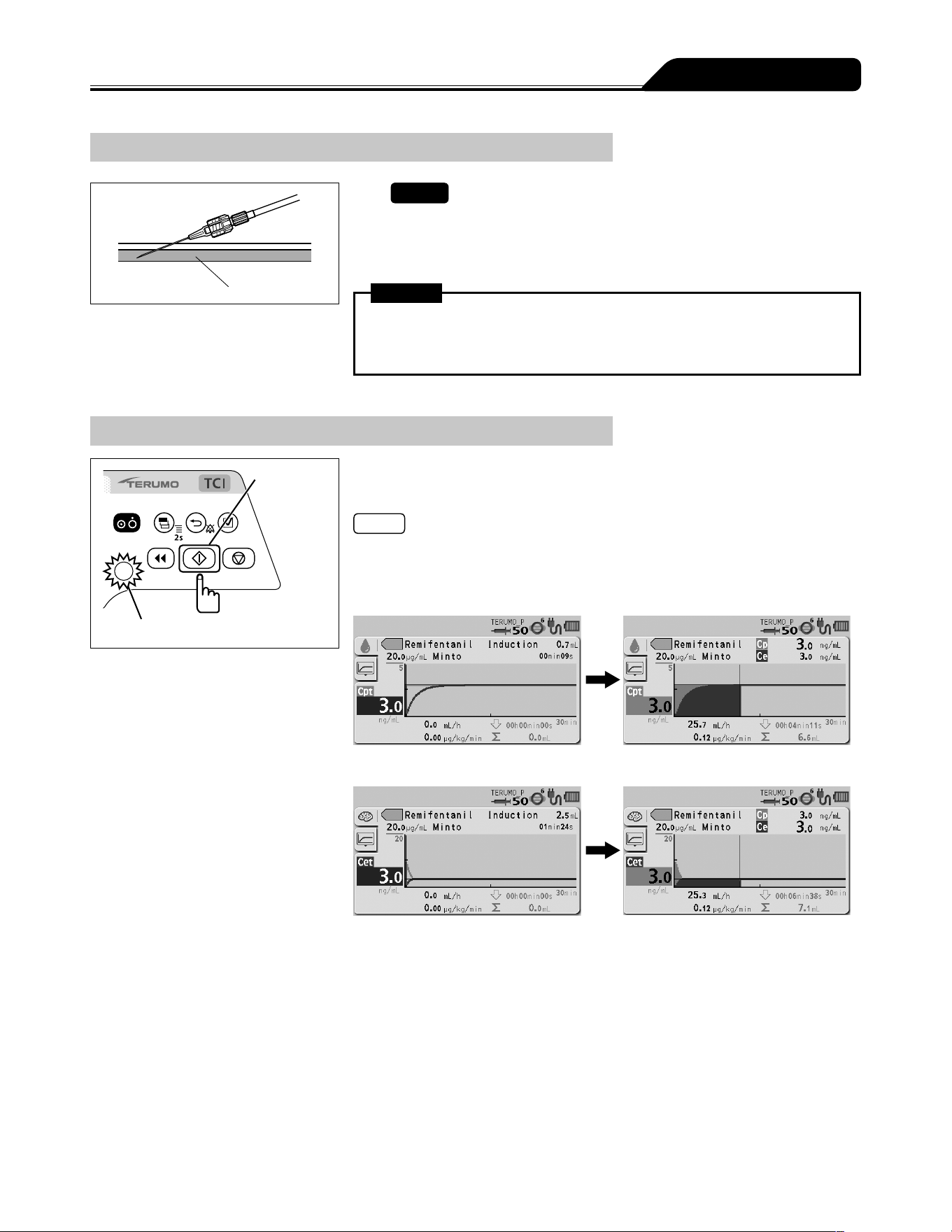
39
Operation Procedure
Inserting a Needle
Vein
1)
Check
The pump is stopped.
2) Insert the needle according to the internal hospital
procedures.
Warning
This product does not have an alarm function to detect extravascular infusion
due to intravenous needle coming out of vein. Periodically check the puncture
site.
Starting Solution Delivery
Start switch
Operation indicator (green flashing)
Check the setting of target concentration (Cpt or Cet) and
press the Start switch to start solution delivery.
Notes
The buzzer sounds.
The operation indicator flashes green.
The displayed values and the graph change in a time lapse.
Plasma TCI
Effect-site TCI
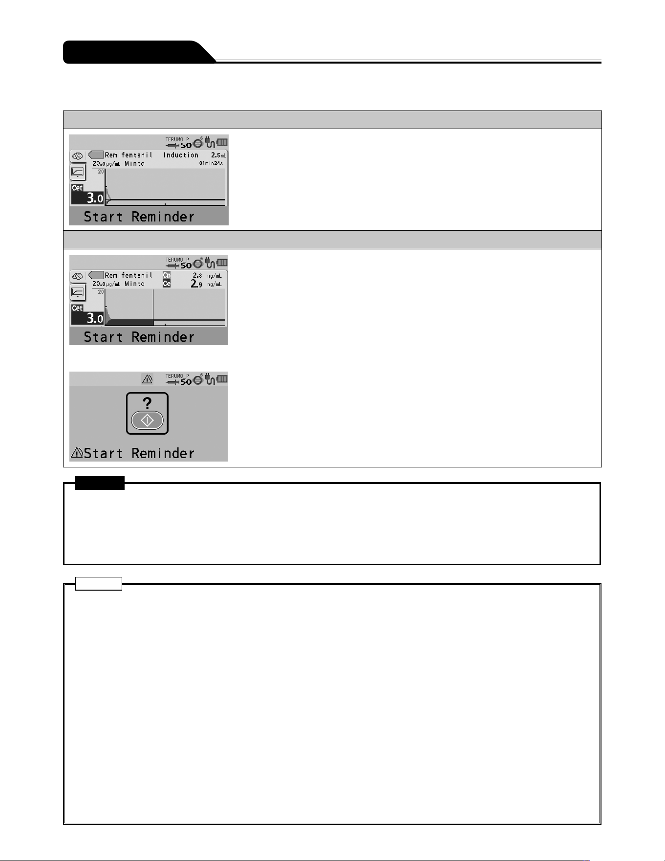
40
Operation Procedure
Start Reminder
Before the first solution delivery starts (when the pump is ready to start)
1. The Start Reminder message appears flashing in the lower
section of the LCD.
2. The buzzer sounds every minute of no operation.
* When the target concentration (Cpt or Cet) is 0.0, no message is displayed and no
buzzer sounds.
After the first solution delivery starts (when the pump is ready to start)
1. The Start Reminder message appears flashing in the lower
section of the LCD.
2. The buzzer sounds every 30 seconds of no operation.
* When the target concentration (Cpt or Cet) is 0.0, no message is displayed and no
buzzer sounds.
↓
More than 2 minutes (when the pump is stopped)
3. The LCD displays the Start Reminder screen (yellow) and
the buzzer sounds.
* Use the standby function (see page 65) to temporarily extend the Start
Reminder.
Warning
Since TCI mode operation is based on plasma or effect-site concentration prediction, the user must observe the patients
condition, assuming there is always the possibility that actual concentration differs from the predicted values. If any
abnormality is found in the patients condition, immediately take appropriate measures such as manual dose or other
options for anesthesia. Improper TCI infusion with predicted concentration mistaken as actual concentration may result in
critical harm to the patient.
Cautions
When infusing in the TCI mode, the following must be observed:
Do not inject the same drug before starting solution delivery in the TCI mode.
After ending the TCI mode, do not inject to the same patient again in the TCI mode during the period that the drug is
assumed to remain in the patients body.
Do not inject the same drug from another route during solution delivery in the TCI mode.
Do not use the Purge switch to inject drugs to a patient.
Otherwise, the prediction of concentration will be affected since the value is determined based on the calculation of
discharge quantity from the syringe in the TCI mode.
Before starting solution delivery in the TCI mode, make sure all the settings such as the digits of target concentration
are correct. This product does not have a function to determine the correct values, possibly resulting in excessive or
insufficient infusion to the patients.
If soft and hard limits are not activated before starting solution delivery, check the settings for any mistakes such as
an error in the digit of flow rate. This product does not have a function to determine whether or not the set values are
appropriate, possibly resulting in excessive infusion or insufficient infusion to a patient.
Do not turn off the power or end the TCI mode while the TCI mode is in use. Otherwise, all important information on the
current TCI mode, such as the predicted concentration, will be erased.
If any fault is observed, immediately stop the solution delivery and check the setting and the attachment status of the
syringe.
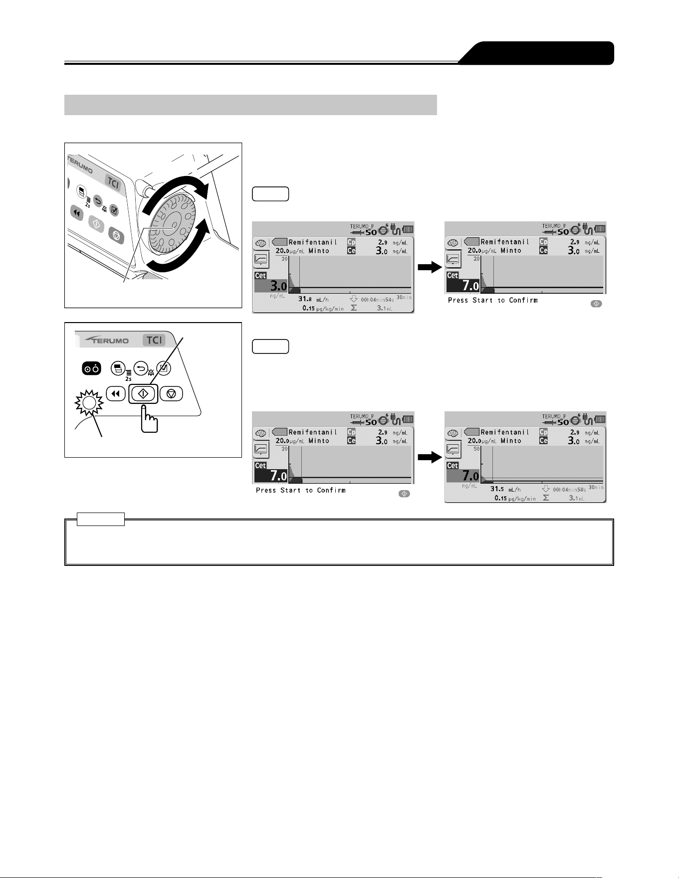
41
Operation Procedure
Changing the target concentration (Cpt or Cet)
The target concentration (Cpt or Cet) can be changed during solution delivery.
Increases value
Dial
Decreases
value
1) During solution delivery, turn the Dial with the graph or text
screen displayed to change the target concentration (Cpt or
Cet).
Note
The confirmation message Press Start to Confirm is displayed on the LCD.
Start switch
Operation indicator (green flashing)
2) Press the Start switch.
Notes
The target concentration (Cpt or Cet) is confirmed.
The buzzer sounds.
The operation indicator flashes green.
The line indicating the target concentration (Cpt or Cet) in the graph is updated.
Caution
If the Start switch is not pressed within approximately 5 seconds, the setting is not applied and the previously set value is
restored. Be sure to press the Start switch to apply the setting in order to achieve the expected performance.
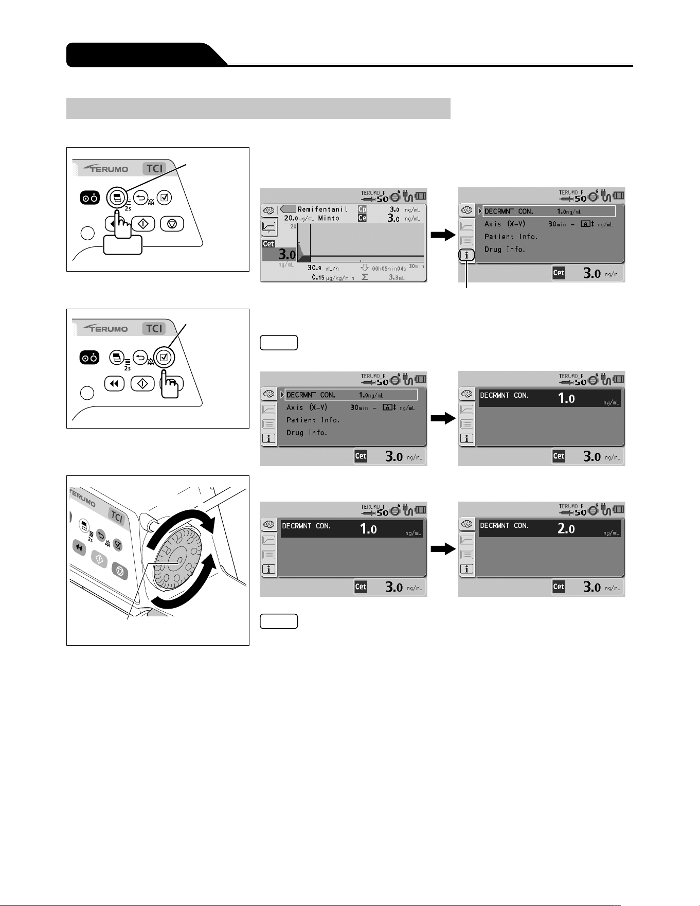
42
Operation Procedure
Changing the decrement concentration
The decrement concentration can be changed.
Display
select switch
Twice
1) Press the Display select switch twice, then select the Info
tab.
Info tab
Confirmation
switch
2) Press the Confirmation switch to select DECRMNT CON.
Note
The display returns to the graph screen after 10 seconds of no operation.
Increases value
Dial
Decreases
value
3) Turn the Dial to change the value of DECRMNT CON.
Notes
The decrement concentration can be set within the range of the following values:
0.1 to 15.0 μg/mL in 0.1 μg/mL step (Propofol)
0.1 to 50.0 ng/mL in 0.1 ng/mL step (Remifentanil)
The default setting of the decrement concentration is 1.2 μg/mL (Propofol) or
1.0 ng/mL (Remifentanil).
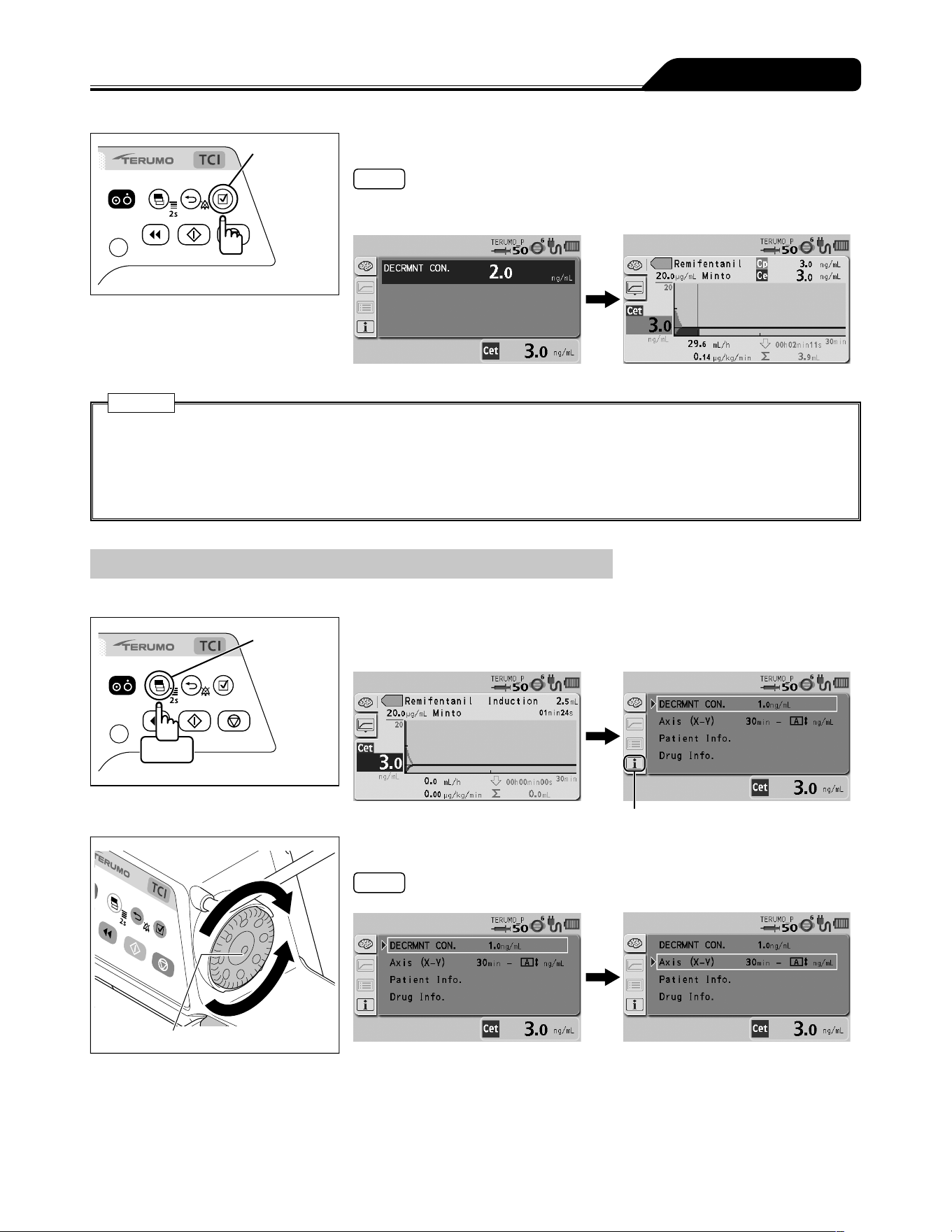
43
Operation Procedure
Confirmation
switch
4) Press the Confirmation switch.
Notes
The display returns to the graph screen after the Confirmation switch is pressed.
The decrement time is updated.
Caution
After a certain period of time of no operation in the process, the display changes as described below. In this case, the
setting is not applied and the previously set value is restored.
During solution delivery: The display returns to the graph screen after 5 seconds of no operation.
While the pump is stopped: The display returns to the graph screen after 10 seconds of no operation.
Be sure to press the Confirmation switch to apply the setting in order to achieve the expected performance.
Changing Scales
The scales of the X axis (time) and Y axis (plasma or effect-site concentration) in a graph can be changed.
Display
select switch
Twice
1) Press the Display select switch twice, then select the Info
tab.
Info tab
Dial
2) Turn the Dial to select Axis (X-Y).
Note
The display returns to the graph screen after 10 seconds of no operation.
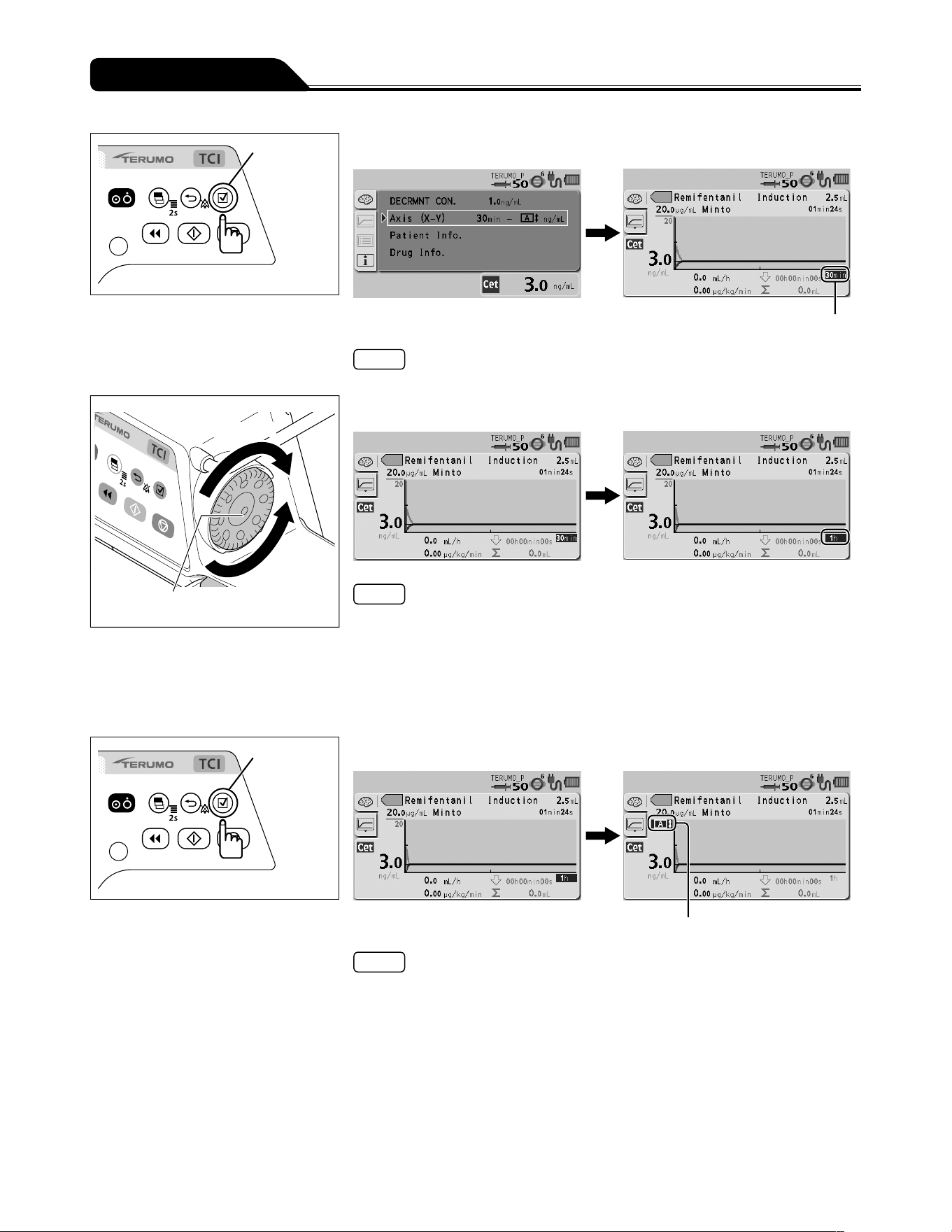
44
Operation Procedure
Confirmation
switch
3) Press the Confirmation switch.
X axis
Note
The display returns to the graph screen and the X axis turns dark blue (selected).
Increases value
Dial
Decreases
value
4) Turn the Dial to change the scale of the X axis (time).
Notes
The scale of the X axis can be selected from AUTO, 30min, 1h, 2h, 4h, 8h, and
16h.
The default setting of the X axis is 30min.
When AUTO is selected, the scale changes stepwise from 30min to 16h, with
a bar displayed under the number indicating the current scale. This will change
accordingly the update interval of the graph indicating the predicted plasma
concentration (Cp) and predicted effect-site concentration (Ce).
Confirmation
switch
5) Press the Confirmation switch.
Y axis
Note
The scale of the X axis is confirmed and the Y axis turns dark blue (selected).
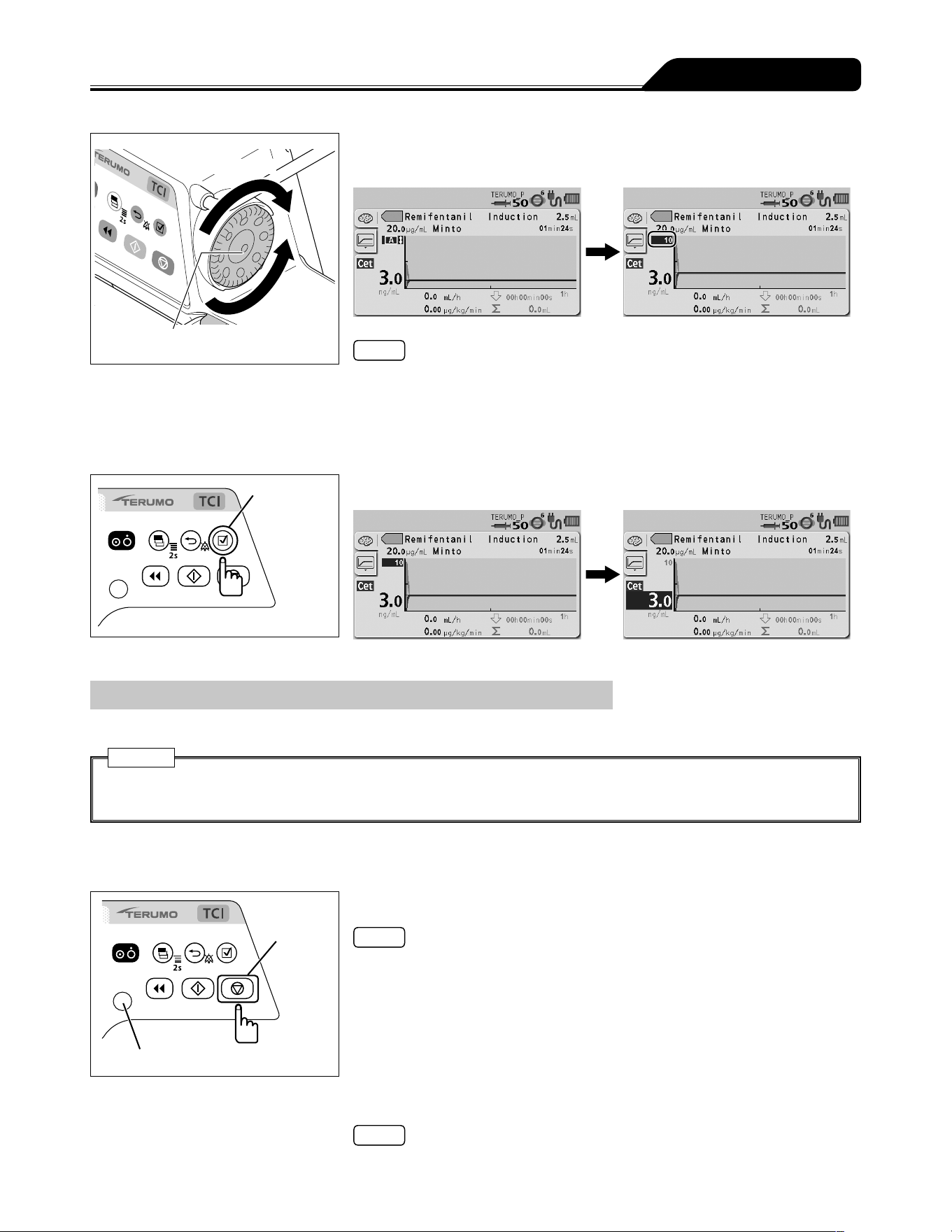
45
Operation Procedure
Increases value
Dial
Decreases
value
6) Turn the Dial to change the scale of the Y axis (plasma or
effect-site concentration).
Notes
The scale of the Y axis can be selected from AUTO, 0.1, 0.2, 0.5, 1, 2, 5, 10, 20,
50, 100, 200, 500, 1000, and 2000.
The default setting of the Y axis is AUTO.
When AUTO is selected, the suitable scale is automatically selected so that the
entire graph is displayed on the screen. A bar appears above the number indicating
the currently selected scale.
Confirmation
switch
7) Press the Confirmation switch.
Replacing the Syringe
Solution delivery can be continued by replacing the syringe with a new one.
Caution
To continue the TCI infusion to the same patient, do not turn off the power while replacing the syringe with a new one.
Otherwise, all important information on the current TCI mode, such as the predicted concentration, will be erased.
1) To continue solution delivery when the remaining amount in
the syringe is low, prepare a new one.
Stop switch
Operation indicator
2) Press the Stop switch.
Notes
The buzzer sounds and the operation indicator turns off, then solution delivery
stops.
The predicted concentration remains displayed while the pump is stopped.
3) Close the infusion line.
Note
For details on stopping solution delivery, see page 61.
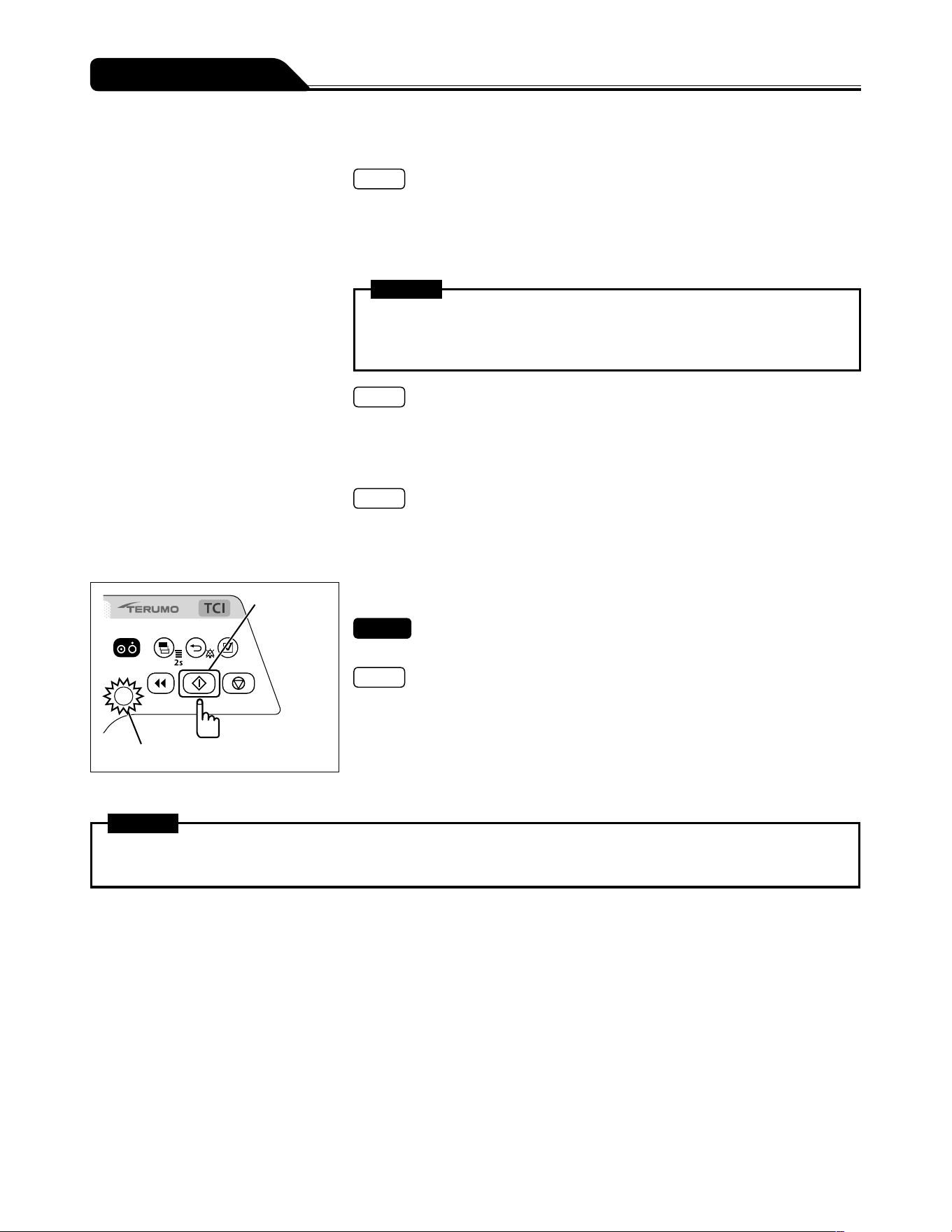
46
Operation Procedure
4) Remove the syringe.
Note
For details on removing the syringe, see page 61.
5) Check that the syringe brand to be used matches the
syringe brand displayed on the LCD, and then place the
syringe.
Warning
Before using the TCI mode, make sure the correct drug name, model, and
target concentration are displayed. Incorrect settings of those may cause
significant health hazard to the patient.
Note
For details on setting the syringe, see page 32.
6) Perform priming before starting solution delivery to the
patient, and keep the plunger pushed by the slider.
Note
For details on priming, see page Priming on page 38.
7) Switch the solution delivery to the patient side, and open the
infusion line.
Start switch
Operation indicator (green flashing)
8) Press the Start switch.
Check
The setting of target concentration (Cpt or Cet) should be correct.
Notes
The buzzer sounds.
The operation indicator flashes green.
Warning
When removing the syringe installed in this product, first close the three way stopcock etc. of the infusion line. Otherwise
excessive infusion (siphoning free flow by gravity) of the drug solution may occur.
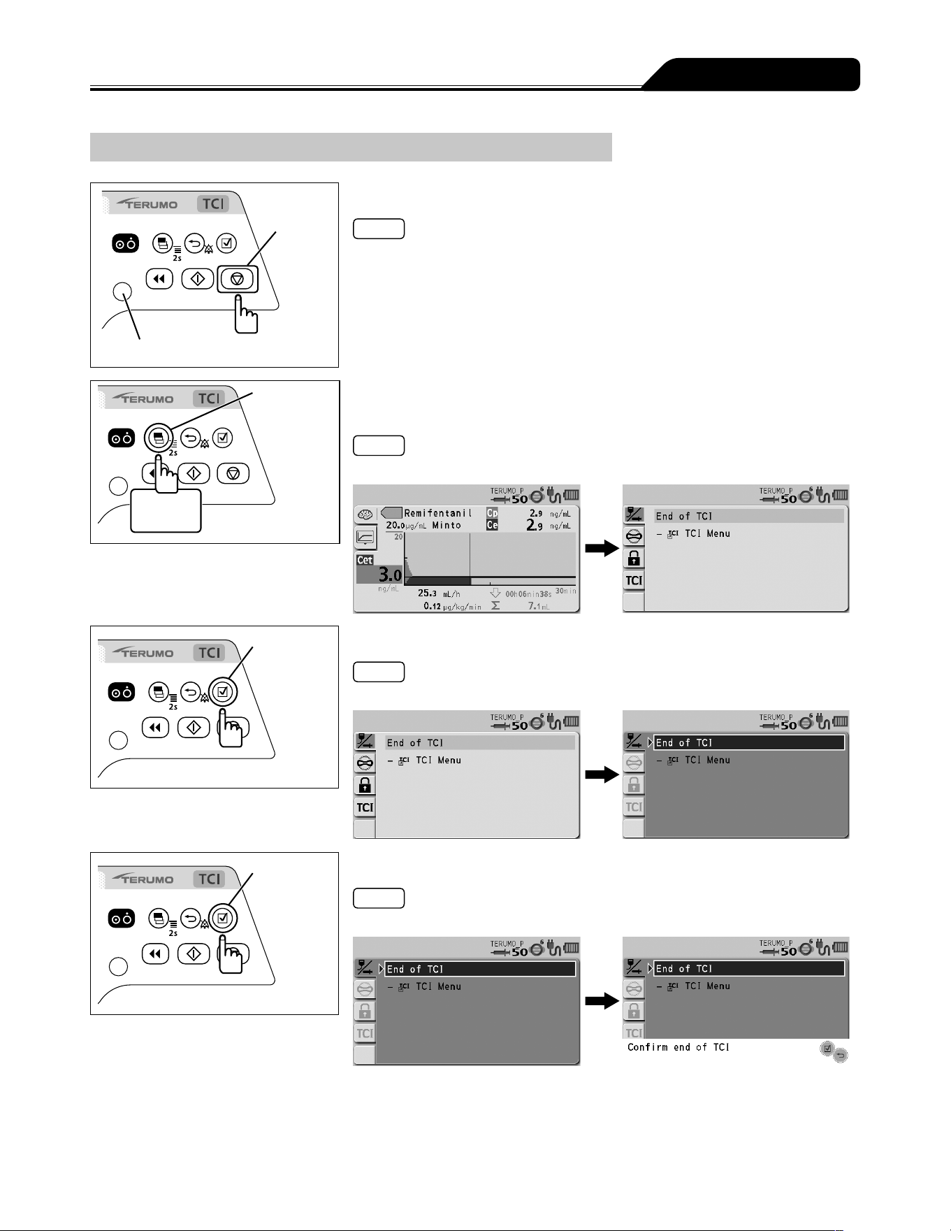
47
Operation Procedure
Ending the TCI mode
Stop switch
Operation indicator
1) Press the Stop switch.
Note
The buzzer sounds and the operation indicator turns off, then solution delivery
stops.
Display
select switch
2 seconds
or more
2) Press and hold the Display select switch for 2 seconds or
more.
Note
The menu 1 screen (End of TCI screen) is displayed.
Confirmation
switch
3) Press the Confirmation switch.
Note
The display returns to the graph screen after 10 seconds of no operation.
Confirmation
switch
4) Press the Confirmation switch to select End of TCI.
Note
Confirm end of TCI is displayed on the LCD.
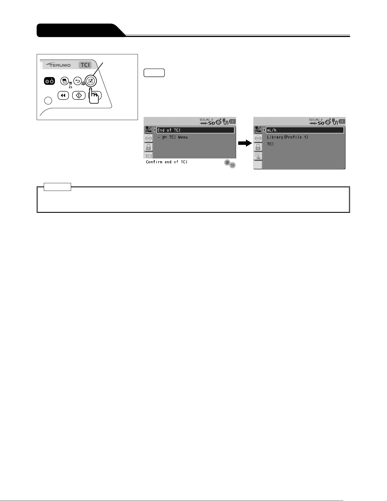
48
Operation Procedure
Confirmation
switch
5) Press the Confirmation switch.
Notes
The buzzer sounds.
The TCI mode ends and the menu 1 screen (Dose mode select screen) is
displayed.
To use the mg/kg/h+DIPRIVAN mode, see Selecting Dose Mode (Weight Mode)
(except TCI) (Default: disabled) (page 75).
Caution
Do not end the TCI mode while the TCI mode is in use; otherwise, all important information on the current TCI mode, such
as the predicted concentration, will be erased.
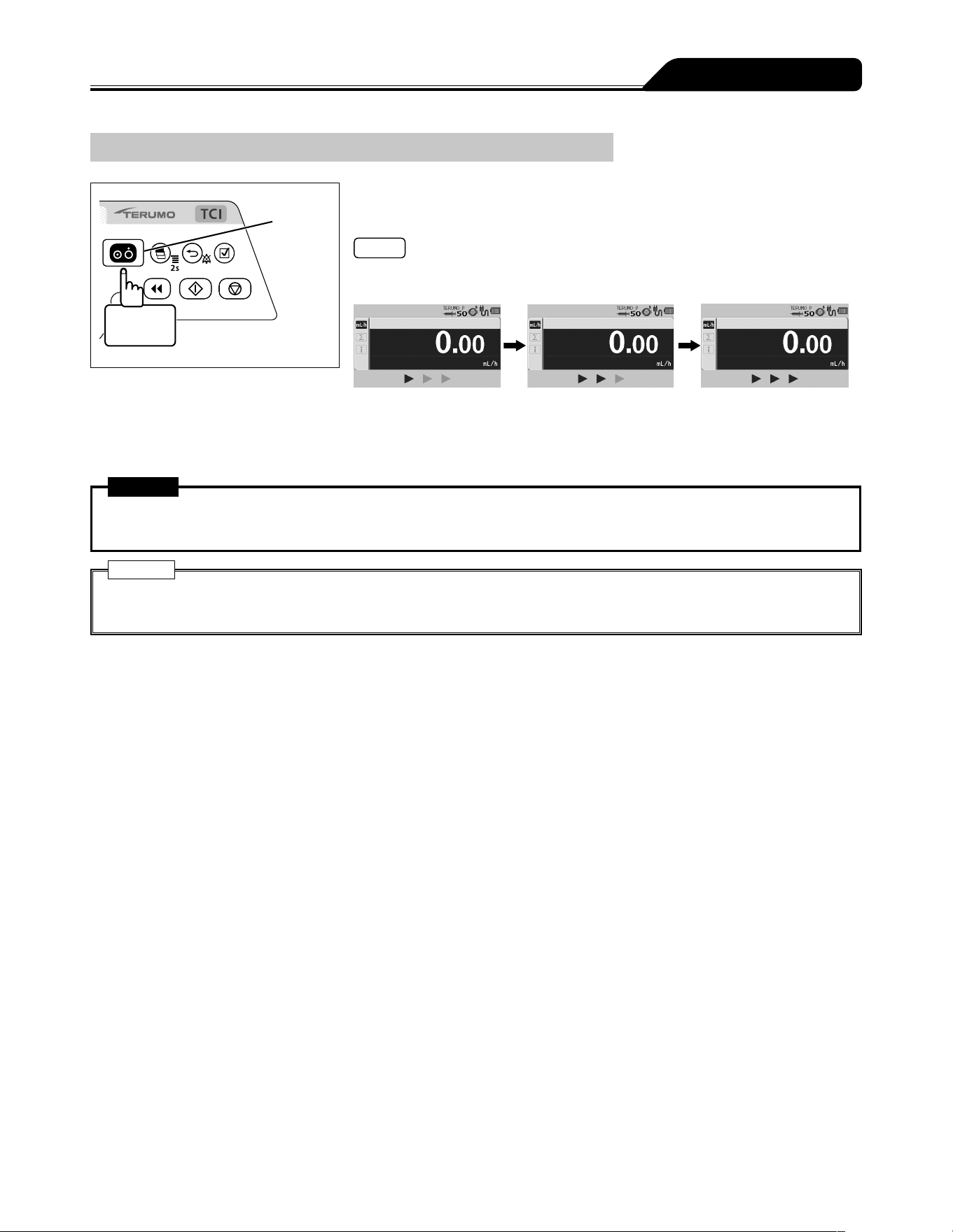
49
Operation Procedure
Turning the Power Off
Power switch
3 seconds
or more
When the operation ends, press and hold the Power switch
for 3 seconds or more to turn the power off.
Notes
While holding the Power switch, the power off buzzer sounds, then the LCD displays
count-down arrows and turns off.
If the Power switch is pressed and held without ending the TCI mode, a buzzer
sounds indicating that the TCI mode is in use. The buzzer continues to sound for
approx. 3 seconds until the power is turned off.
Warning
While in the TCI mode, never inject the drug to the same patient again after completion. Doing so may result in an
overdose.
Caution
Do not turn off the power while the TCI mode is in use; otherwise, all important information on the current TCI mode, such
as the predicted concentration, will be erased.
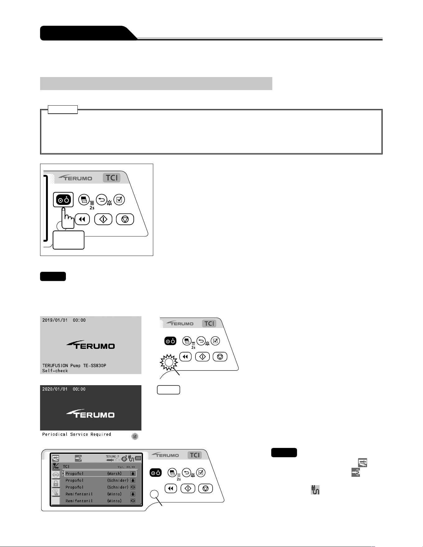
50
Operation Procedure
Using other dose modes
Turning the Power On
Please ensure the product is fit for purpose prior to use.
Cautions
Conduct the self-check (self-diagnosis) of this product without a syringe installed. Otherwise the self-check may not be
conducted properly.
Check for any fault by conducting a self-check. If a fault is observed, immediately discontinue use and contact TERUMO
trained service technicians.
1 second
or more
Press and hold the Power switch for 1 second or more until
the TERUMO logo screen is displayed to turn the power on.
Checks
When turning the power on, the following occur simultaneously;
TERUMO logo appears on the display.
LCD flashes 3 times.
Operation indicator repeats lighting green and red alternately, and then buzzer sounds.
Operation indicator
Notes
A timer for maintenance can be set in this product. When the period set for the
maintenance timer is reached, a maintenance request is displayed at start up.
When the request is displayed, contact TERUMO trained service technicians.
When the period set for the maintenance timer is reached, this screen displays
at every start up until the setting is changed. For the setting method, contact
TERUMO trained service technicians.
Operation indicator
Checks
The syringe displacement icon
and
the slider displacement icon are
displayed flashing on the LCD.
The AC icon is displayed.
The battery icon is displayed, not
indicating the sub-battery failure.
The operation indicator is off.
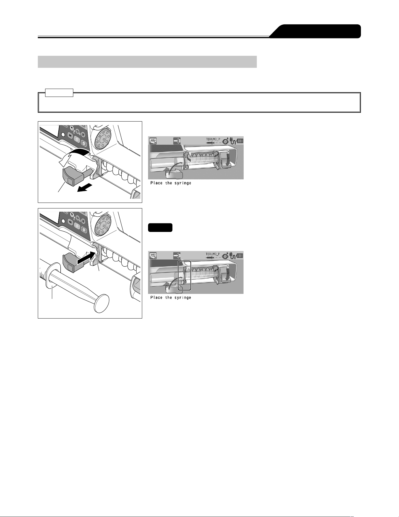
51
Operation Procedure
Setting the Syringe
1) Close the infusion line and attach a syringe filled with solution to it using aseptic technique.
Caution
Only use specified syringes with luer lock for the pump.
Clamp
1
2
2) Pull the clamp forward and turn.
Slit
Flange
3) Insert the flange into the slit.
Checks
Check the LCD as shown below.
The syringe flange is correctly fitted into the slit.
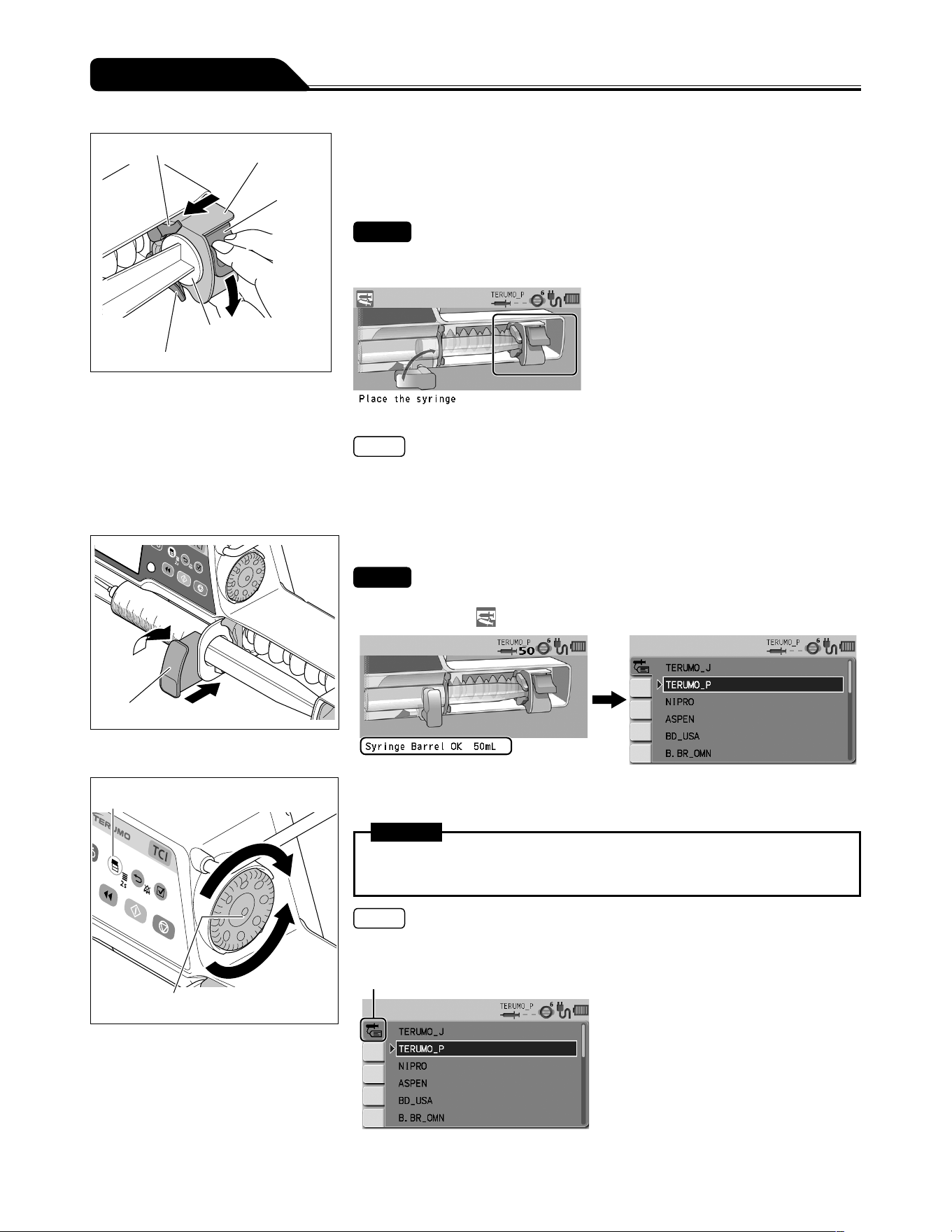
52
Operation Procedure
Slider hook
Slider
Clutch
Plunger
Slider hook
4) While holding the clutch, move the slider until it meets the
plunger, and then release the clutch.
If the following guidance in the figure below does not
display, perform this step again.
Checks
The clutch appearing in the LCD should look as shown below.
The slider displacement icon is turned off.
Note
If the process is not completed after several attempts, the clutch may be ill fitting.
Ensure that the infusion line is not attached to a patient and then apply light
pressure to the slider to push the clutch into position.
The clutch may click when fitted into the position.
Clamp
2
1
5) Turn the clamp and gently push it to fix the syringe.
Check
The message Syringe Barrel OK xx mL is displayed on the LCD, and the syringe
displacement icon is not displayed. (xx is the size of the held syringe.)
Display select switch
Dial
6) Turn the Dial or press the Display select switch to select the
correct syringe brand.
Warning
After the syringe type is selected, recheck that the setting has been adjusted
correctly.
Notes
Turning the Dial or pressing the Display select switch moves the white frame.
The pump will automatically detect the syringe size.
Syringe brand tab
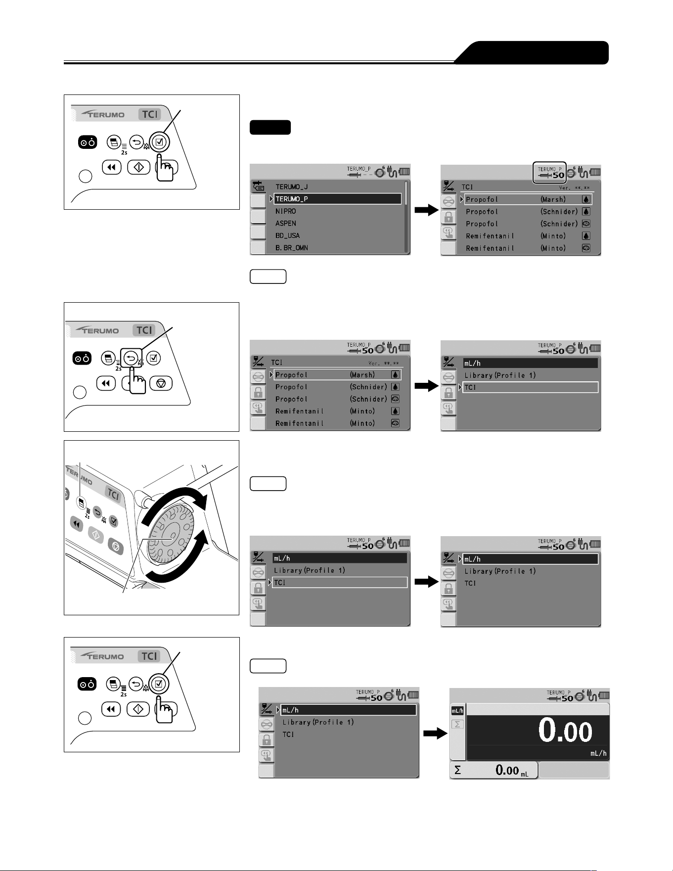
53
Operation Procedure
Confirmation
switch
7) Press the Confirmation switch.
Check
The syringe brand and the syringe size are displayed on the LCD correctly.
Note
If the flow rate screen appears, go to step 11).
Back/Mute switch
8) Press the Back/Mute switch.
Display select switch
Dial
9) Turn the Dial or press the Display select switch to select
the dose mode.
Notes
This section shows an example of selecting mL/h for the dose mode.
For other dose modes, see pages 66 and 75.
Turning the Dial or pressing the Display select switch moves the white frame.
Confirmation
switch
10) Press the Confirmation switch.
Note
When the Confirmation switch is pressed, the flow rate display appears.
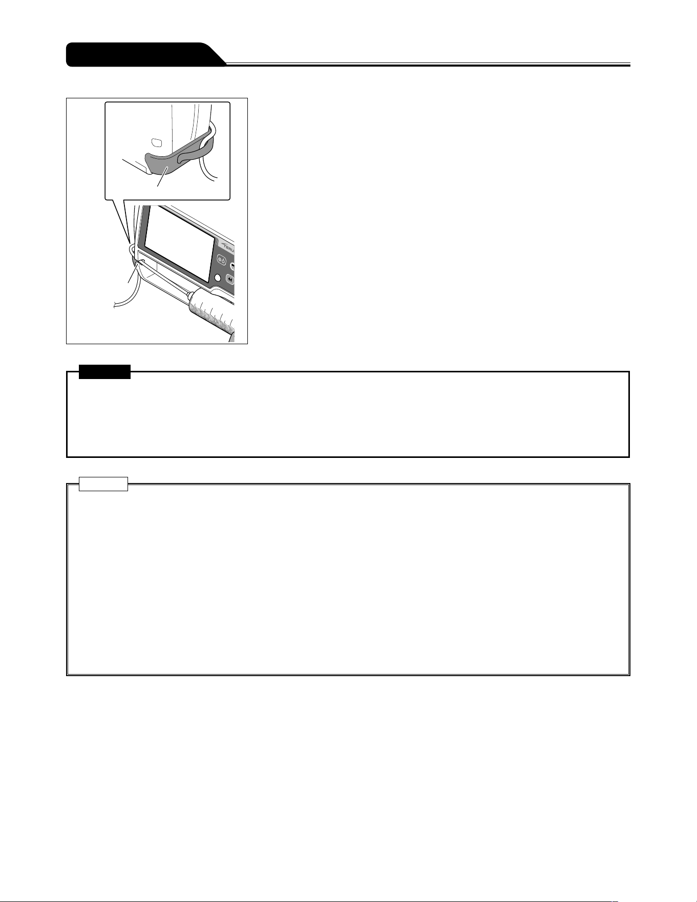
54
Operation Procedure
Tube holder
Tube guide
11) Insert the tube completely into the tube guide and set the
tube to the tube holder.
Warning
When setting a syringe, ensure that the syringe plunger has been firmly set onto the slider hook and that the syringe has
been correctly set and that the flange of the syringe has been inserted into the flange holder. The elevation difference
between this product and the patient should be kept to a minimum. Drug solution may not be delivered correctly due to
rapid infusion caused by displacement of the syringe plunger from the slider hook, incorrect detection of the syringe size,
etc.
Cautions
When setting a plunger into the slider, check that there is no gap between the plunger of the syringe and the slider. If the
plunger is set with gap between them, air or drug solution may be drawn in by the slider hook.
If the LCD displays the syringe displacement icon and the buzzer sounds, check the syringe has been set correctly, and
re-set if necessary. If the syringe is not installed at the correct position, the solution delivery cannot be started.
Even after the syringe is set in the proper position, if any fault is observed, immediately stop using the product and contact
TERUMO trained service technicians.
When installing a syringe, make sure that the syringe size and brand displayed on the LCD correspond to the syringe. If
they do not correspond with each other, it may cause unintended solution delivery.
When installing a syringe, pull forward the clamp and turn. Then, after the syringe is set, turn the clamp back to the
original position and gently push it to fix the syringe. In addition, the slider should be moved while holding the clutch. Any
unreasonable operation or excess operation will cause failure of this product.
When using a syringe (specified sterile syringe for general use) for this product, ensure that the nominal capacity of the
syringe is not exceeded. If exceeded, the accuracy of flow rate or the alarm function cannot be guaranteed.
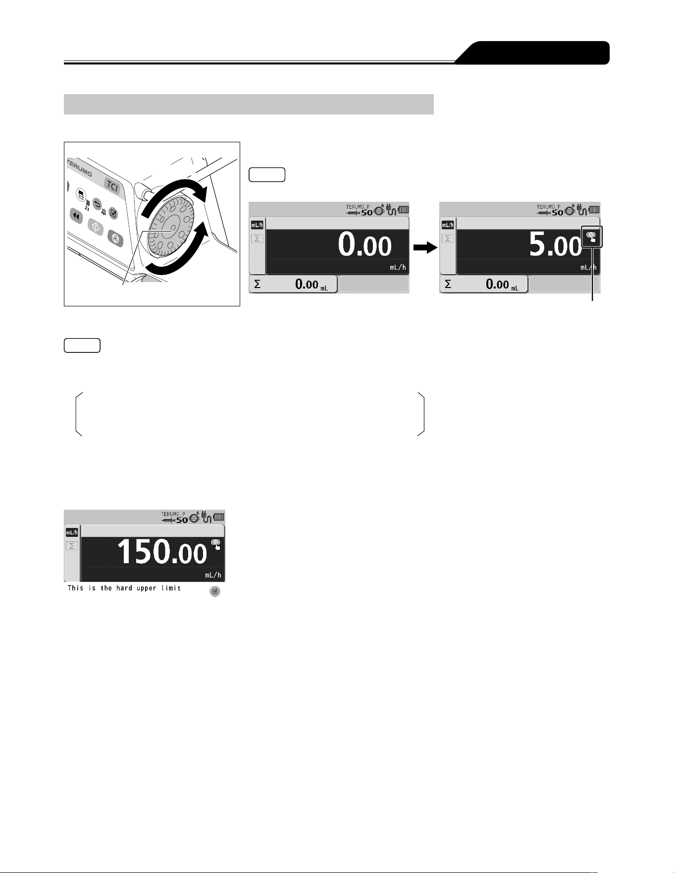
55
Operation Procedure
Setting Flow Rate
Set the flow rate per hour.
Increases value
Dial
Decreases
value
Use the Dial to adjust the flow rate in the flow rate screen.
Note
The flow rate screen appears in dark blue (selected).
Start up icon
Notes
The flow rate can be set within the range of the following values.
Setting range:
0.01 to 150.00 mL/h
Note that the upper limit of the flow rate can be changed in the following ranges:
0.01 to 150.00 mL/h (when using syringe of 5 mL)
0.01 to 300.00 mL/h (when using syringe of 10 mL, 20 mL, 30 mL)
0.01 to 1200.00 mL/h (when using syringe of 50/60 mL)
Step:
0.01 mL/h step (0.01 to 10.00 mL/h)
0.10 mL/h step (10.00 to 100.00 mL/h)
1.00 mL/h step (100.00 to 1200.00 mL/h)
When 150.00 mL/h is reached, the confirmation message This is the hard upper limit is displayed on the LCD.
For safety, the Dial is designed to make the initial half turn without changing the value on the display. When the value starts
to change, the buzzer sounds momentarily for confirmation. When you stop rotating the Dial and start it again in less than 1.5
seconds, the value changes without the initial half turn.
Rotating the Dial while pressing the Stop switch allows changing the setting at the rate of 100 times.
When the Dial is turned, a line appears under the numerals to indicate the currently changing digit. (When the Dial is rotated
while pressing the Stop switch, an underline appears to the second digit to the left from the normal digit.)
The set flow rate can be changed during solution delivery. When the Dial is turned on the flow rate screen during solution
delivery, the flow rate setting area turns dark blue where the set flow rate increases or decreases in accordance with the Dial
operation. The Start switch confirms the set flow rate and changes the solution flow rate. (When the Start switch is not pressed
within approx. 5 seconds, it returns to the set flow rate before change.)
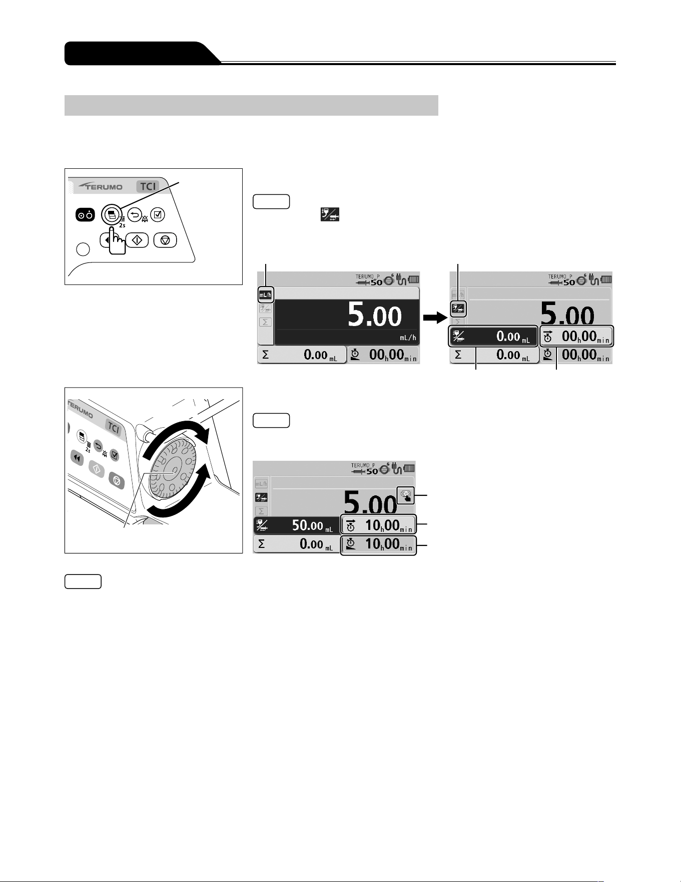
56
Operation Procedure
Setting VTBI
Set the VTBI for the solution delivery (Default: disabled).
To activate this feature, contact TERUMO trained service technicians.
Setting VTBI to enable (ON) also sets VTBI time to enabled (ON).
Display
select switch
1) Press the Display select switch to select the VTBI display.
Notes
The VTBI tab is selected.
The flow rate display shows the VTBI display and the VTBI time display.
The VTBI display appears in dark blue (selected).
Flow rate tab VTBI tab
VTBI display VTBI time display
Increases value
Dial
Decreases
value
2) Use the Dial to adjust the VTBI.
Note
When the flow rate has already been entered, the VTBI time display indicates the
remaining time and VTBI time calculated from the flow rate and VTBI.
Start up icon
VTBI time
Remaining time
Notes
The VTBI can be set from 0.10 to 9999.00 and ----.-- (Unlimited).
To set to unlimited, turn one rotation or more in the direction of decreasing the Dial when VTBI is 0.
In the case of a solution delivery with no setting for the VTBI (----.--: Unlimited), the pump will not stop until the Syringe Empty
is issued due to running out drug solution, and therefore the product should be stopped before running out of the drug solution.
The VTBI can also be set in mass units. In this case, VTBI can be set from 0.01 ng to 9999.99 kg and ----.-- (Unlimited). (When
the selecting dose mode (weight mode/drug library) is set.)
If not operated for 10 seconds, the input area moves to the flow rate display.
VTBI can be changed only when delivery is stopped.
Rotating the Dial while pressing the Stop switch allows changing the setting at the rate of 100 times.
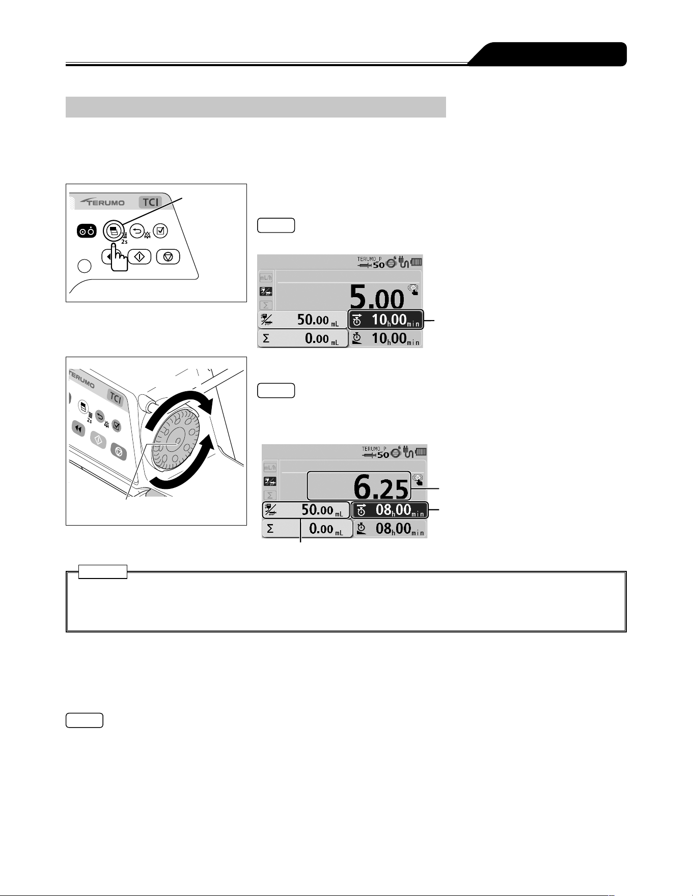
57
Operation Procedure
Setting VTBI Time
Set up the time period to complete the dose (Default: disabled).
The flow rate is recalculated from the VTBI and VTBI time specified.
To activate this feature, contact TERUMO trained service technicians.
Setting VTBI to enable (ON) also sets VTBI time to enabled (ON).
Display
select switch
1) Press the Display select switch to select the VTBI time
display.
Note
The VTBI time display appears in dark blue (selected).
VTBI time display
Increases value
Dial
Decreases
value
2) Use the Dial to adjust the VTBI time.
Notes
The VTBI time can be set between 00 h 01 min and 99 h 59 min.
When the VTBI is set to ----.-- (Unlimited), the VTBI time cannot be set.
If not operated for 10 seconds, the input area moves to the flow rate display.
Flow rate
VTBI time
VTBI
Cautions
The flow rate is updated according to the VTBI and VTBI time. Before starting solution delivery, check the value.
When using the VTBI time setting function, the setting cannot take a flow rate (mL/h) calculation result outside the flow rate
setting range, and therefore it should be reconfigured. [----.--] or [0.00] is displayed, not allowing solution delivery.
Keep Vein Open (KVO) Function
When the volume delivered reaches the VTBI, the KVO function is activated for the prevention of thrombus formation, and thus the
flow rate is automatically changed to 0.1 mL/h. If the set flow rate is lower than the flow rate of the KVO, solution delivery continues
at the set flow rate. If you wish to change the flow rate of the KVO, contact TERUMO trained service technicians.
Notes
The KVO is a flow rate set in advance to operate under certain conditions in order to keep the patient line open.
Note that the symbol KOR (Keep Open Rate) is commonly used as an alias for KVO.
According to IEC 60601-2-24:2012 (EN 60601-2-24:2015), clause 201.3.209, KVO (Keep Vein Open) is commonly used as a
synonym for KOR (Keep Open Rate).
Stopping Keep Vein Open
1) Press the Back/Mute switch twice to stop the alarm and return to flow rate screen.
2) Press the Stop switch to cancel the Keep Vein Open (KVO) function and the operation stops.
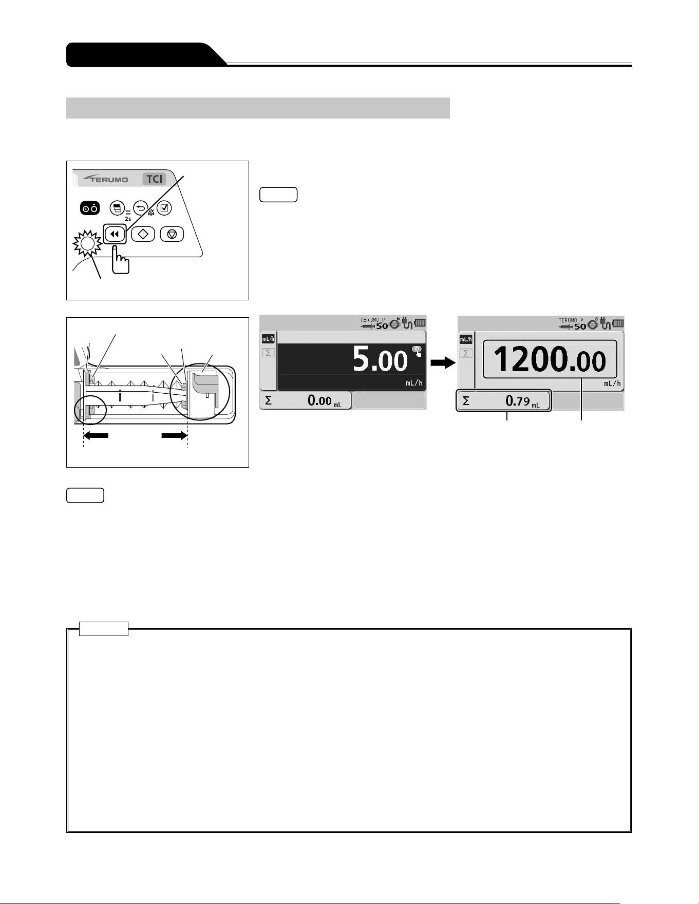
58
Operation Procedure
Priming
Before connecting the infusion line to the patient, perform priming to extract air from the line.
Purge switch
Operation indicator (green flashing)
Flange
Flange holder
Slider hook
Plunger
Slider
The syringe is
fit exactly.
Press and hold the Purge switch to perform priming.
Notes
During the priming operation, the buzzer sounds and the operation indicator
flashes green.
During the priming operation, the purge flow rate is displayed on the flow rate
display.
If any other switch is pressed while the Purge switch is pressed, the safety function
detects it as an abnormal operation and stops purging.
After the priming operation is finished, the screen transits to the flow rate screen.
Volume delivered Flow rate display
(purge flow rate)
Before starting solution delivery During priming
Notes
The syringe size and the purge flow rate are as follows:
When using syringe of 5 mL: approx. 150 mL/h
When using syringe of 10 mL: approx. 300 mL/h
When using syringe of 20 mL: approx. 400 mL/h
When using syringe of 30 mL: approx. 500 mL/h
When using syringe of 50/60 mL: approx. 1200 mL/h
With the Purge switch pressed and held, the volume delivered display shows the volume purged.
The upper limit of purge volume can be set. Contact TERUMO trained service technicians.
The priming function will not work when the syringe pump is stopped by an alarm.
Cautions
Before inserting an intravenous needle or connecting an infusion line with the connecting site, always prime the infusion
line by pressing the Purge switch. This product may cause harm to a patient due to air injection, since it does not have a
function to detect air in the infusion line.
Failure by any mechanical gap may cause considerable delay in the start of the infusion.
This is especially the case when a large syringe (e.g. 50 mL) is used at very low flow rate settings and/or when anti-siphon
valves are used in the infusion line.
Use the priming function to remove any mechanical gap: between the syringe plunger and the slider; between the flange
and the syringe pump slit.
When purging the solution, note that the volume purged is not added to the volume delivered. If this is not considered, the
volume delivered will differ from the actual infusion volume.
When purging a drug solution with high viscosity through a thin intravenous needle, an Occlusion alarm is likely to be
issued even if the infusion line is not occluded. To deliver a solution with high viscosity, deliver it at the rate of 100 mL/h or
lower, not by purging it. If purging is continued, an Occlusion alarm may frequently be issued or the solution may be unable
to be delivered.
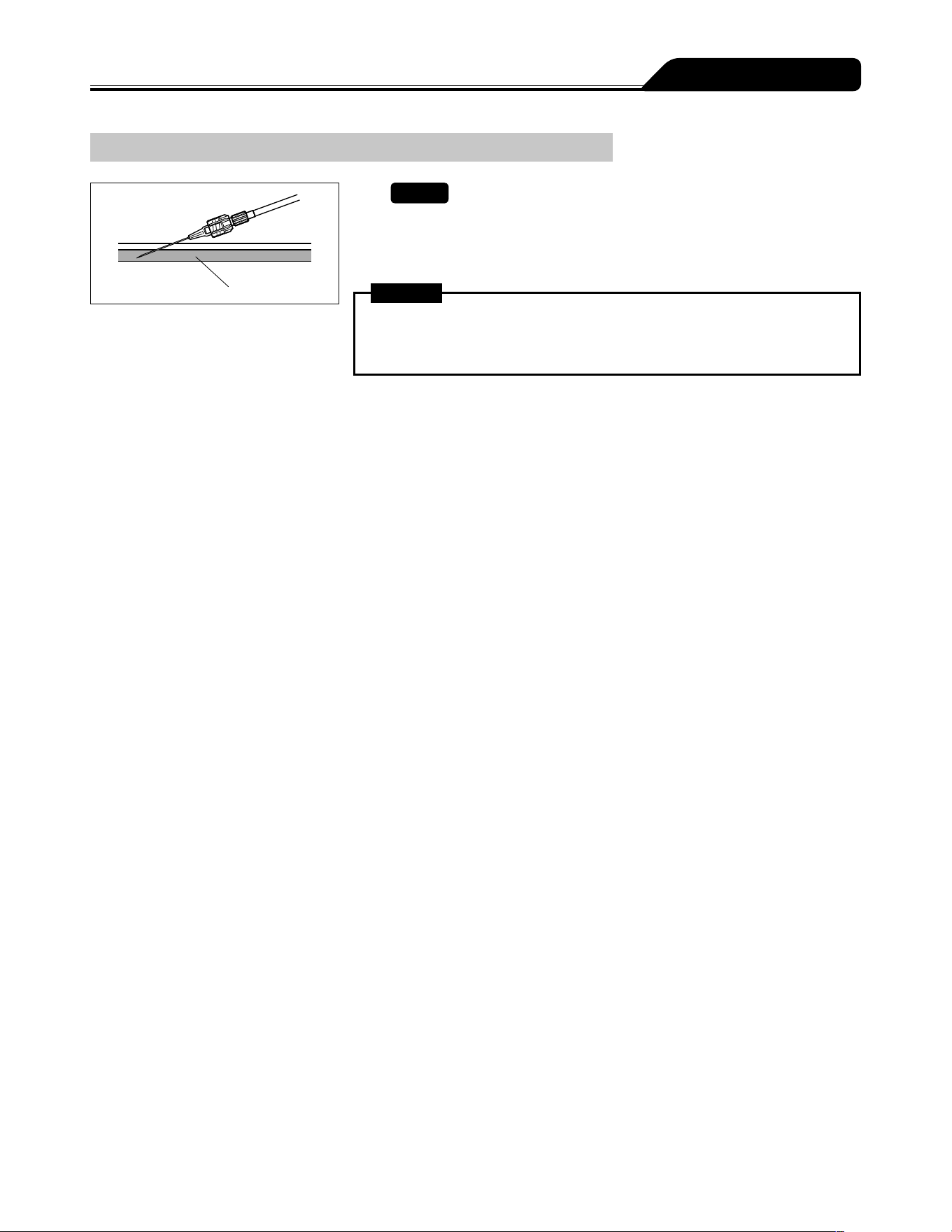
59
Operation Procedure
Inserting a Needle
Vein
1)
Check
The pump is stopped.
2) Insert the needle according to the internal hospital
procedures.
Warning
This product does not have an alarm function to detect extravascular infusion
due to intravenous needle coming out of vein. Periodically check the puncture
site.
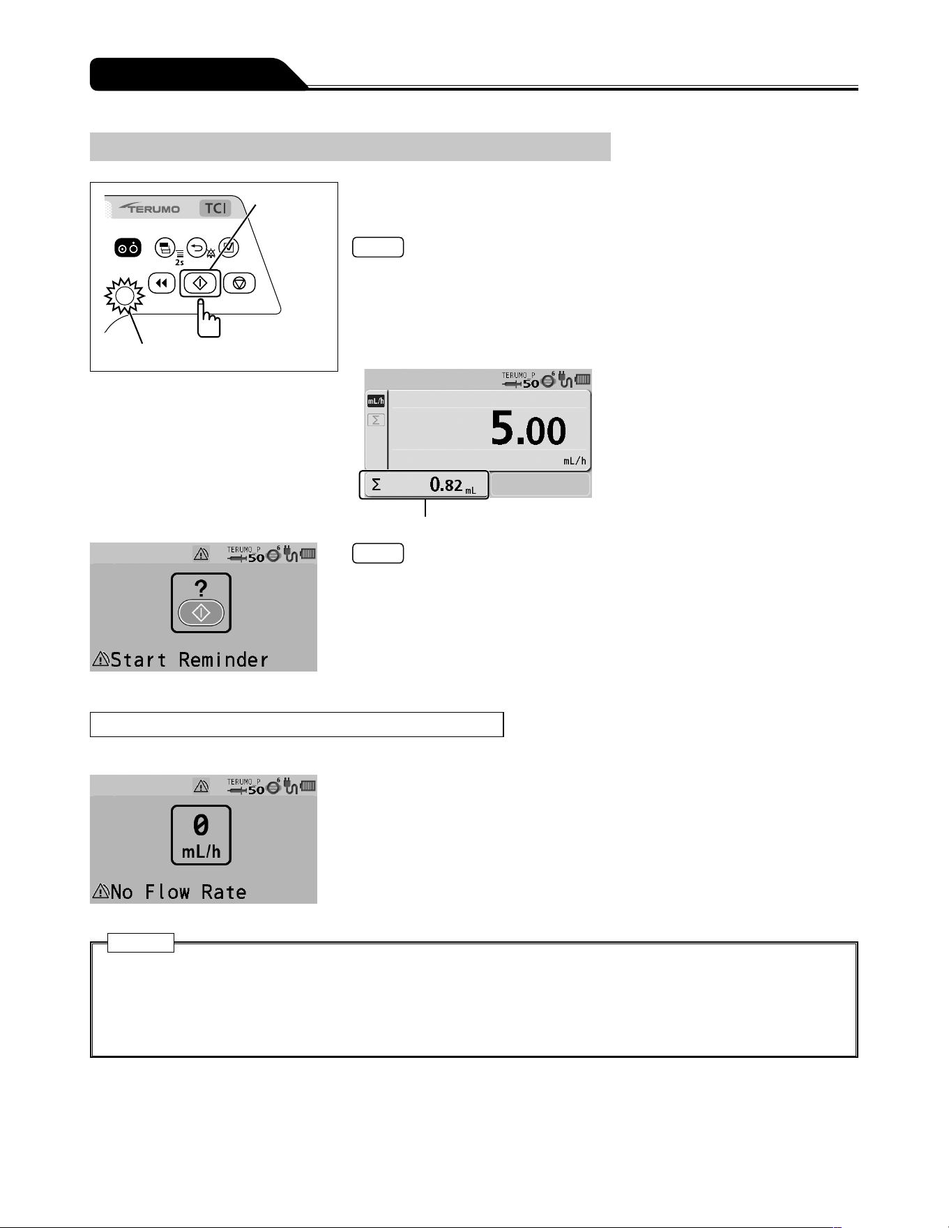
60
Operation Procedure
Starting Solution Delivery
Start switch
Operation indicator (green flashing)
Check the flow rate setting and press the Start switch to
start solution delivery.
Notes
The buzzer sounds.
The operation indicator flashes green.
The volume delivered increases.
Flow rate can be changed during solution delivery. Rotate the Dial in the flow rate
display to change the flow rate and the confirmation message appears. Press the
Start switch to start solution delivery at the changed flow rate.
Volume delivered
Notes
When the pump is fully set but not started, after 2 minutes the LCD displays the
Start Reminder screen (yellow) and the buzzer sounds.
Use the standby function (see page 65) if you want to temporarily extend the
Start Reminder.
When Solution Delivery Cannot Start
The alarm sounds and the following warnings display. (See page 133.)
No Flow Rate alarm (yellow)
The flow rate has not been set. Set the flow rate and press the Start switch again.
Cautions
If soft and hard limits are not activated before starting solution delivery, check the settings for any mistakes such as
an error in the digit of flow rate. This product does not have a function to determine whether or not the set values are
appropriate, possibly resulting in excessive infusion or insufficient infusion to a patient.
If any fault is observed, immediately stop the solution delivery and check the setting and the attachment status of the
syringe.
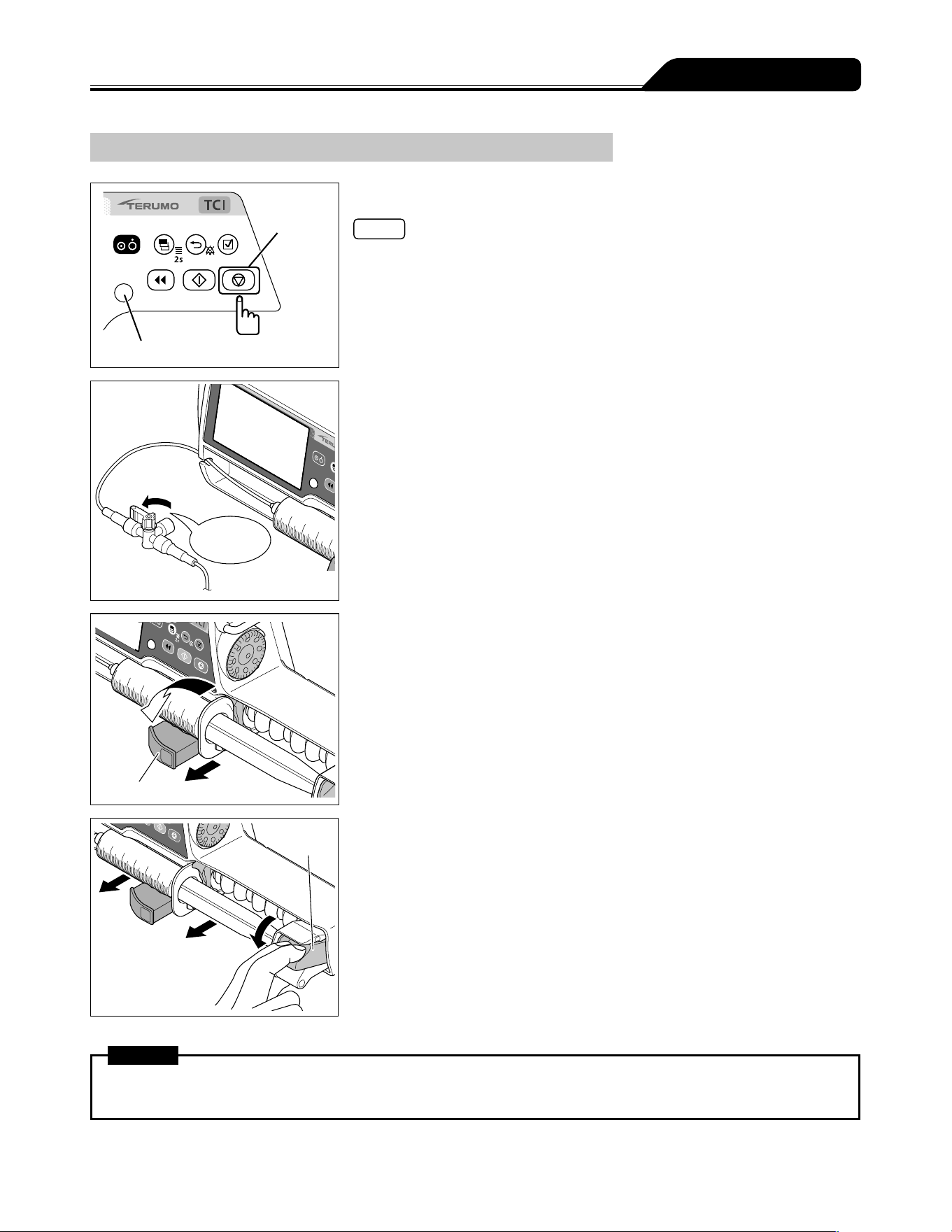
61
Operation Procedure
Stopping Solution Delivery
Stop switch
Operation indicator
1) Press the Stop switch.
Notes
The buzzer sounds and the operation indicator turns off, then the operation stops.
The volume delivered stops increasing.
OFF
Close the three
way stopcock.
2) Close the infusion line.
1
2
Clamp
3) Pull the clamp and then turn.
Clutch
4) While holding the clutch, remove the syringe.
Warning
When removing the syringe installed in this product, first close the three way stopcock etc. of the infusion line. Otherwise
excessive infusion (siphoning free flow by gravity) of the drug solution may occur.
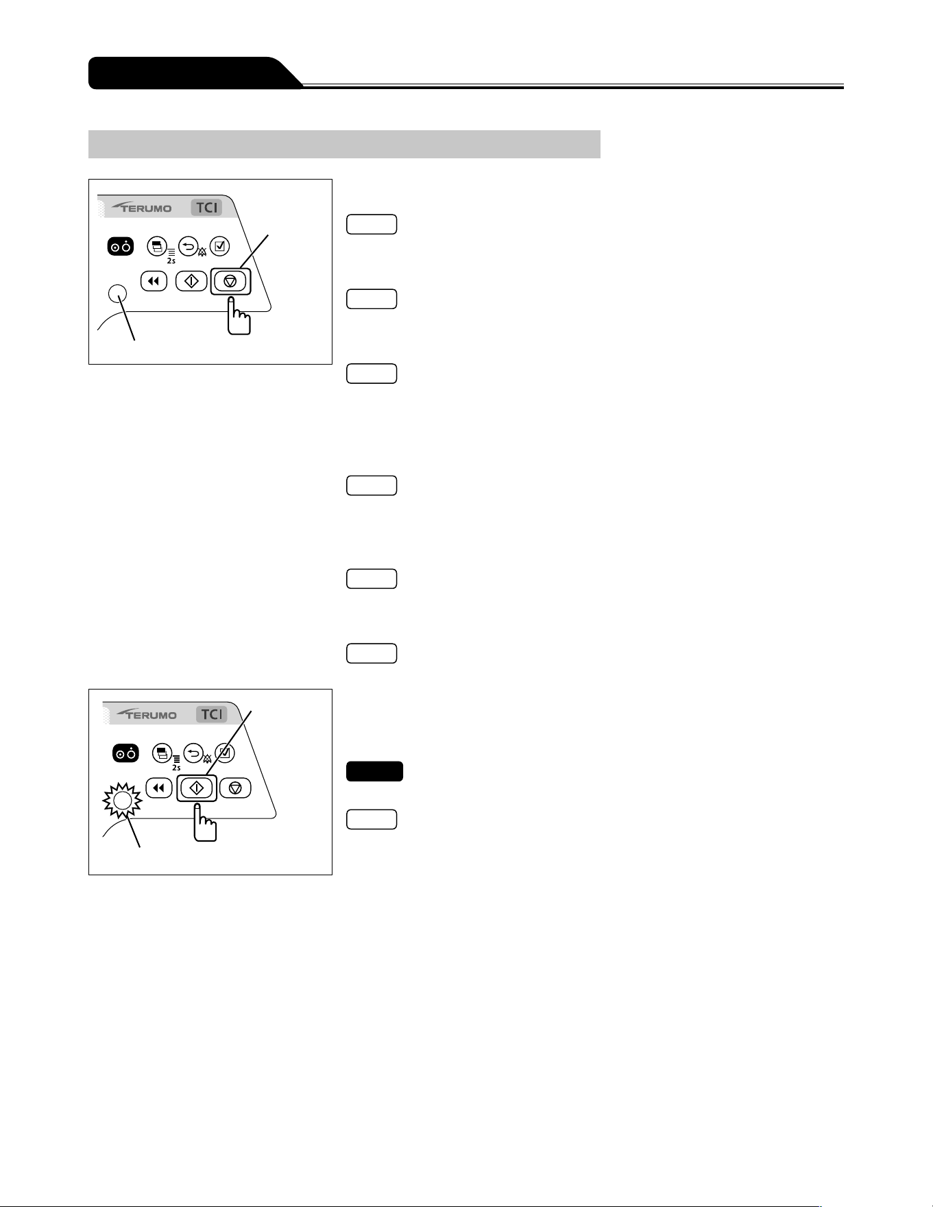
62
Operation Procedure
Replacing Syringe to Continue Solution Delivery
Stop switch
Operation indicator
1) Press the Stop switch to stop the solution delivery.
Note
For details on stopping solution delivery, see page 61.
2) Close the infusion line.
Note
For details on stopping solution delivery, see page 61.
3) Remove the syringe.
Note
For details on removing the syringe, see page 61.
4) Check that the syringe brand to be used matches the
syringe brand displayed on the LCD, and then place the
syringe.
Note
For details on setting the syringe, see page 51.
5) Perform priming before starting solution delivery to the
patient, and keep the plunger pushed by the slider.
Note
For details on priming, see page 58.
6) Clear the volume delivered as required.
Note
For details on clearing the volume delivered, see page 64.
Start switch
Operation indicator (green flashing)
7) Switch the solution delivery to the patient side, open
the infusion line, and then press the Start switch to start
solution delivery.
Check
The flow rate is correctly set.
Notes
The operation indicator flashes green.
The volume delivered increases.
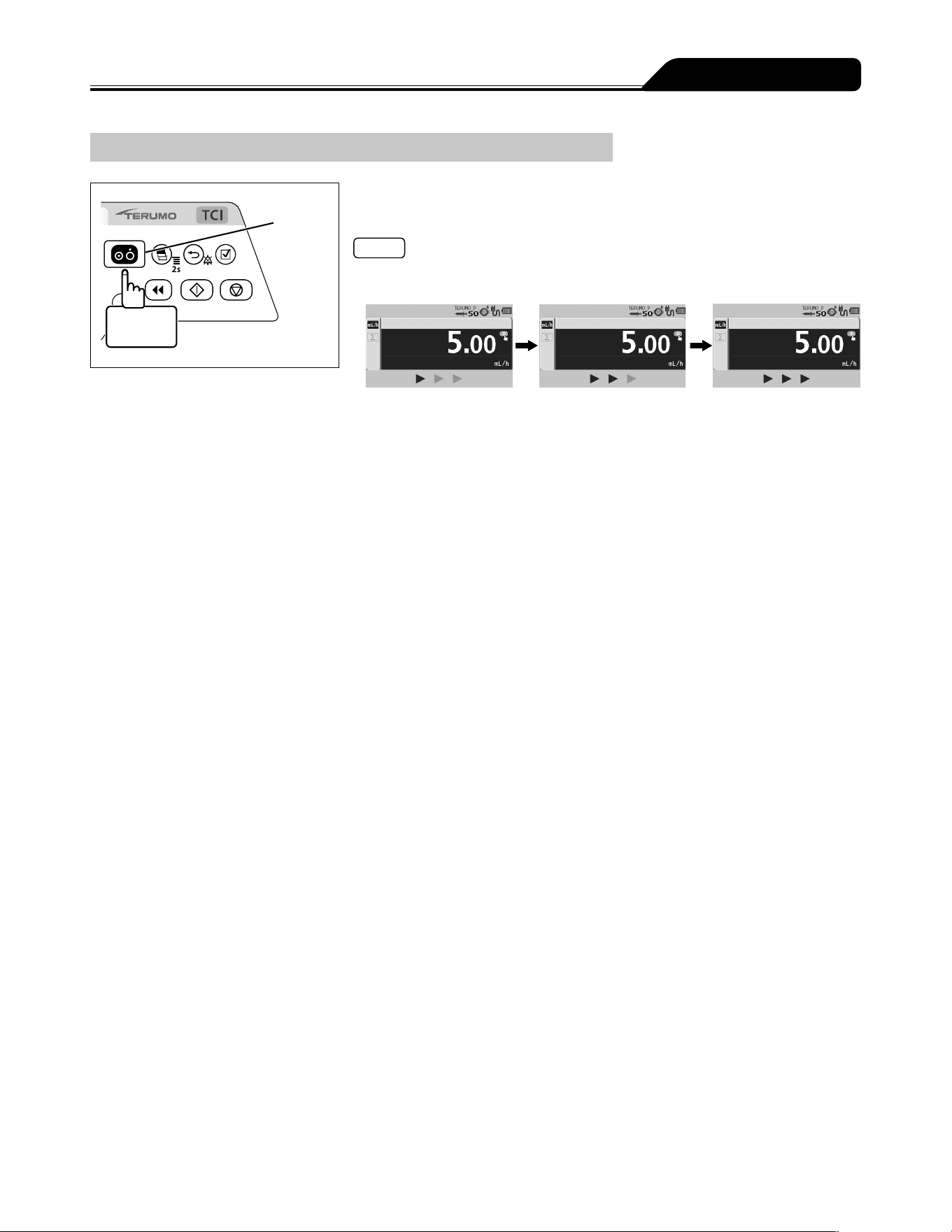
63
Operation Procedure
Turning the Power Off
Power switch
3 seconds
or more
When the operation ends, press and hold the Power switch
for 3 seconds or more to turn the power off.
Notes
While holding the Power switch, the power off buzzer sounds, then the LCD displays
count-down arrows and turns off.
If the Power switch is pressed and held during solution delivery, a buzzer sounds
indicating that solution delivery is in progress. The buzzer continues to sound for
approx. 3 seconds until the power is turned off.
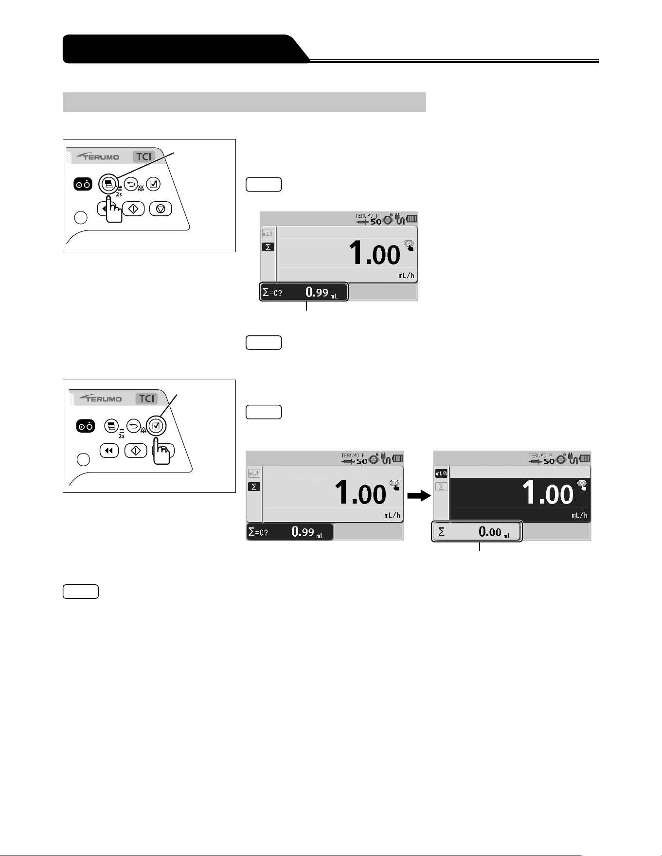
64
Clearing the Volume Delivered (except the TCI mode)
The volume delivered can be cleared.
Display
select switch
1) Press the Display select switch repeatedly until the volume
delivered display is selected.
Note
The volume delivered display appears in dark blue (selected).
Volume delivered display
Note
The volume delivered can be cleared when solution delivery is in progress or when
stopped.
Confirmation
switch
2) Press the Confirmation switch.
Note
The buzzer sounds, the volume delivered is cleared to 0, and the screen returns
to the flow rate screen.
Volume delivered
Notes
When resuming the solution delivery after the value of the volume delivered is cleared to 0 mL, check the flow rate and the
VTBI, and re-set as required.
To check the volume delivered after clearing the value, use the history function. (See page 100.)
Turning the power off clears the volume delivered to 0.
If not operated for 10 seconds, the input area moves to the flow rate display.
Other Operation Procedures
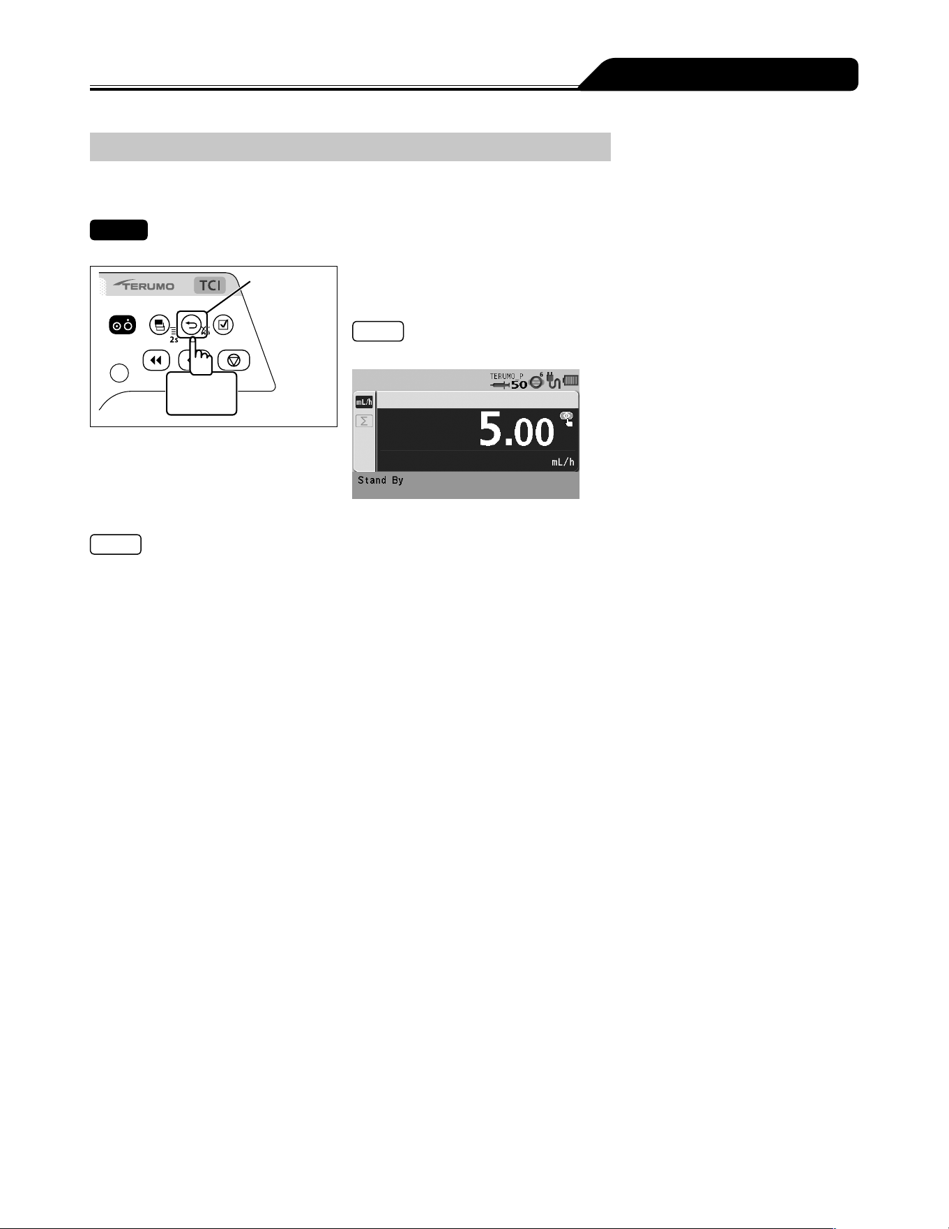
65
Other Operation Procedures
Standby Function
The standby function can extend the Start Reminder.
Check
The syringe is set and the solution delivery is ready to be started.
Back/Mute
switch
2 seconds
or more
Press and hold the Back/Mute switch for 2 seconds or more.
(The standby mode is entered.)
Note
The LCD displays the message Stand By.
Notes
The default standby time is 24 hours. To change this, contact TERUMO trained service technicians (the time can be changed to
24 hours or less).
Turning the Dial or pressing any switch cancels standby mode.
The standby mode cannot be entered when an alarm has been issued. Eliminate the cause of the alarm first.
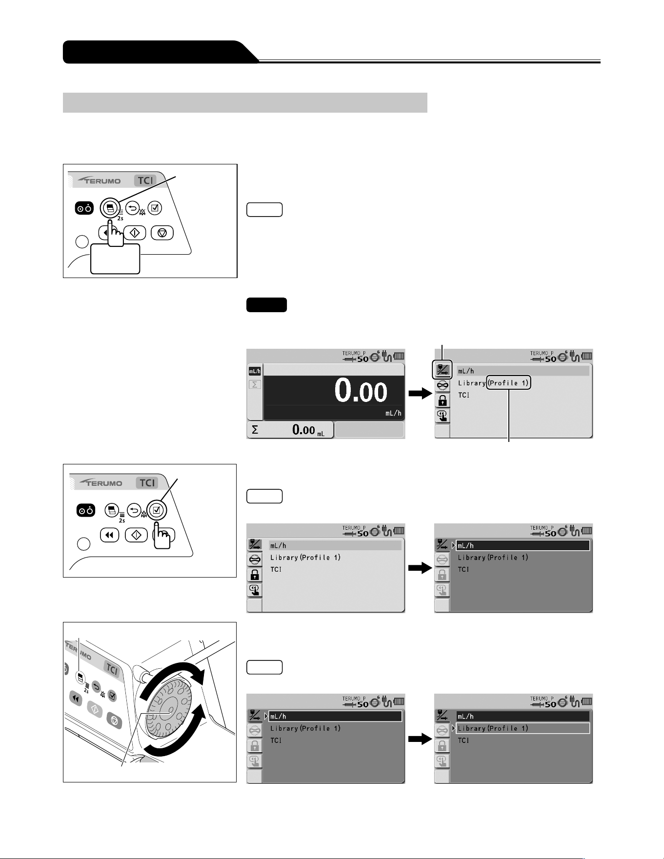
66
Other Operation Procedures
Selecting Dose Mode (Drug Library)
The dose mode can be selected from the drug library.
Use the dedicated editing software (TERUFUSION Drug Library Manager or TERUFUSION Software Package) for registration. For
details, contact TERUMO trained service technicians.
Display
select switch
2 seconds
or more
1) Press and hold the Display select switch for 2 seconds or
more when solution delivery is stopped.
Notes
The menu 1 screen is displayed and then the dose mode select (Dose) display
appears.
The set profile names are displayed next to Library.
Profiles allow drugs to be classified according to their use and registered in the
pump. Selecting a profile can limit the available libraries. To change the profile, see
page 112.
Check
A correct profile name is displayed.
Dose mode select tab
Profile name
Confirmation
switch
2) Press the Confirmation switch.
Note
The existing dose mode (light blue) changes to the selected status (dark blue).
Display select switch
Dial
3) Turn the Dial or press the Display select switch to select the
library.
Note
Turning the Dial or pressing the Display select switch moves the white frame.
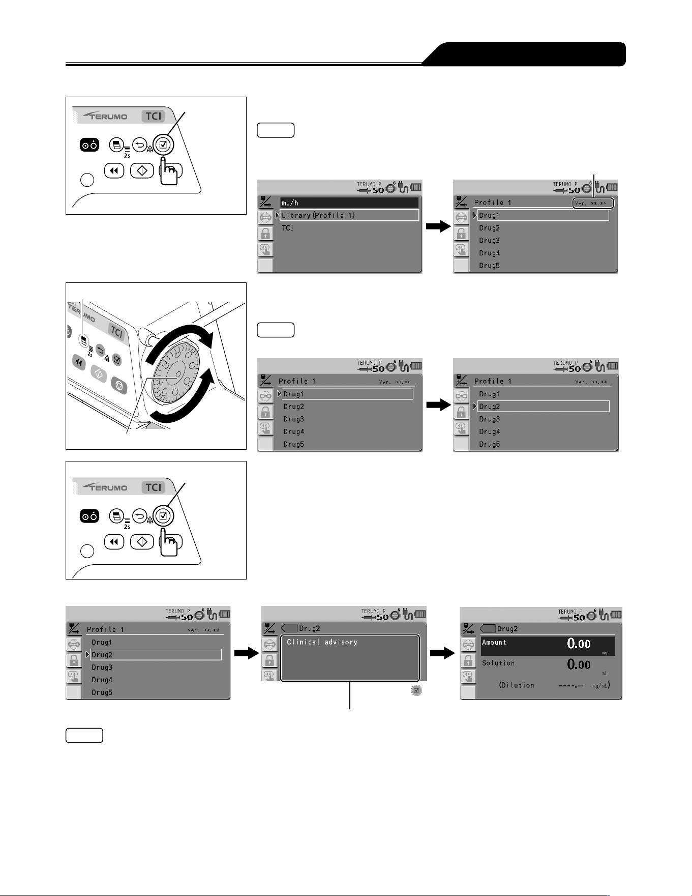
67
Other Operation Procedures
Confirmation
switch
4) Press the Confirmation switch.
Notes
The screen changes to the library selection display.
The selected library is displayed in dark blue.
Drug Library Version
Display select switch
Dial
5) Turn the Dial or press the Display select switch to select the
library name, shown as "Drug2" in the example.
Note
Turning the Dial or pressing the Display select switch moves the white frame.
Confirmation
switch
6) Press the Confirmation switch.
When clinical advisory
*1
is set
Clinical advisory display
Notes
If clinical advisory is set, a message appears. With every press of the Confirmation switch, the screen changes to the input
screen of amount and solution, or the input screen of dilution
*2
. If you want to set by Dilution, contact TERUMO trained service
technicians.
*
1
: Clinical advisory is a function to display a cautionary message about the selected library. The message can be registered
up to 120 characters. See the dedicated editing software (TERUFUSION Drug Library Manager or TERUFUSION Software
Package) for how to set the clinical advisory for each drug library.
*
2
: When the dilution is set in the drug library, the input screen of dilution appears.
When the dose unit is mL/h, the screen changes to the parameter confirmation screen of step 8.
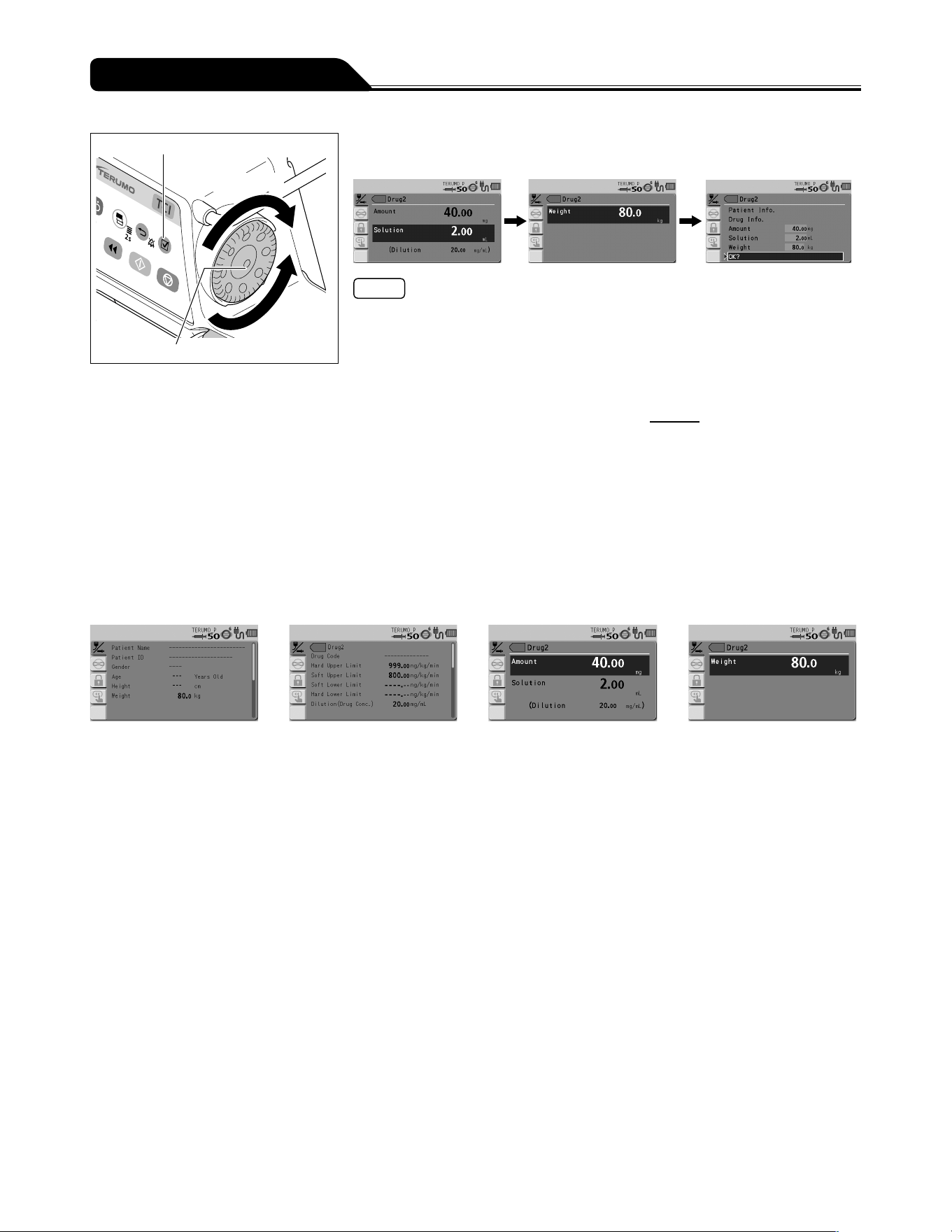
68
Other Operation Procedures
Confirmation switch
Increases value
Dial
Decreases
value
7) If necessary, turn the Dial to set each parameter (amount,
solution, and weight), and press the Confirmation switch.
Notes
When the dilution is set in the drug library, the dilution parameter cannot be
changed.
Amount, solution and weight can be set within the following range.
Amount: 0.01 to 999.00*
Solution: 0.01 to 999.00*
Weight: 0.1 to 300.0 kg
* Can be set within the range of the dilution =
Amount
: 0.01 to 999.00
Solution
With every press of the Confirmation switch, the input area moves to the next one.
When the Back/Mute switch is pressed, the parameter input is cancelled and the
screen returns to the previous status.
When all the parameters are input, the parameter confirmation screen appears.
The background colour of the changed parameter value changes on the parameter
confirmation screen.
When the Back/Mute switch is pressed on the parameter confirmation screen, the
parameter input is cancelled and the screen returns to that of step 5.
Information of the patient and drugs can be checked, or parameter values can be
changed from the parameter confirmation screen.
Patient information screen Drug information screen Parameter value setting screen
(Amount/Solution)
Parameter value setting
screen (Weight)
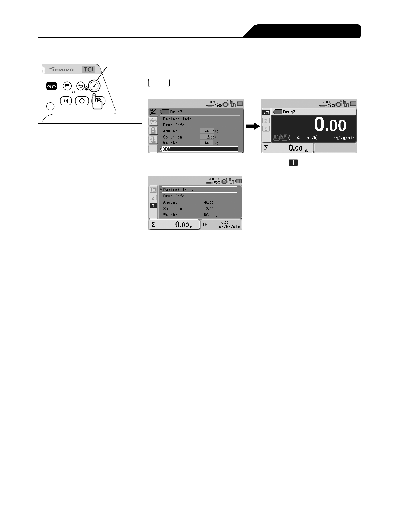
69
Other Operation Procedures
Confirmation
switch
8) Check the parameter value and that OK? is selected, and
press the Confirmation switch.
Notes
When the Confirmation switch is pressed, the flow rate display appears.
When the Display select switch is pressed and info tab is selected, the set
information is displayed.
The following operations can be performed
on this display:
Displaying patient information
Displaying drug information
Changing parameter values
To operate one of these, turn the Dial to select the item and press the Confirmation
switch.
When the Back/Mute switch is pressed on the parameter confirmation screen, the
parameter input is cancelled and the screen returns to the previous status.
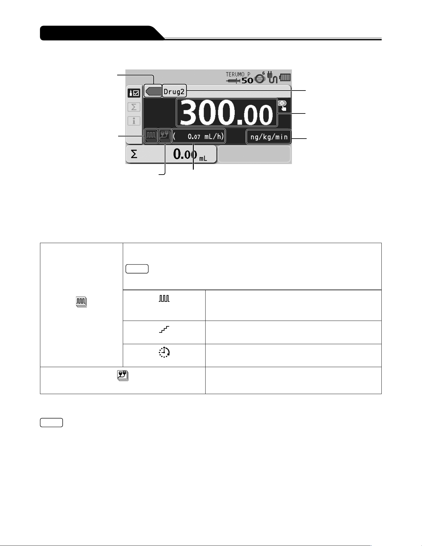
70
Other Operation Procedures
Library display
Colour tag
Advanced dose mode icon
Combination dose mode icon
Flow rate (mL/h)
The flow rate (mL/h) is automatically calculated from
the specified dosage rate, amount, solution, and weight.
When the dose unit mL/h is selected, this is not displayed.
Drug name
Dose rate
Dose unit
Colour tag
Selection is possible from 16 colours.
Advanced dose mode icon/combination dose mode icon
The icon to indicate the dose mode is displayed.
When using an advanced dose mode, see page 96.
Advanced dose mode icon
The icon is displayed when the advanced dose modes below can be selected. For details of each
dose method, see TERUFUSION Drug Library Manager or TERUFUSION Software Package.
Note
If no advanced dose mode can be set for the selected library, the advanced dose mode icon is
not displayed.
Interval/Intermittent
mode icon
Two specified dosage rates are alternately delivered at regular
intervals for the specified number of steps.
Multi-step mode icon
The speed of solution delivery increases or decreases at the
specified levels.
Delayed Start mode icon
Solution delivery starts after the specified time has elapsed.
Combination dose mode icon
For details, contact TERUMO trained service technicians.
See the dedicated editing software (TERUFUSION Drug Library Manager or TERUFUSION Software Package) for how to set
an advanced dose mode and colour tag.
Notes
The Combination Dose Mode which can be used in combination with a rack system (optional accessory) is available in the
library. Contact TERUMO trained service technicians for details.
Pressure alarm is available in the library as a safety function.
See TERUFUSION Drug Library Manager or TERUFUSION Software Package or contact TERUMO trained service
technicians for details.
Come and See ME is available in the library as a special function. See TERUFUSION Drug Library Manager or
TERUFUSION Software Package or contact TERUMO trained service technicians for details.
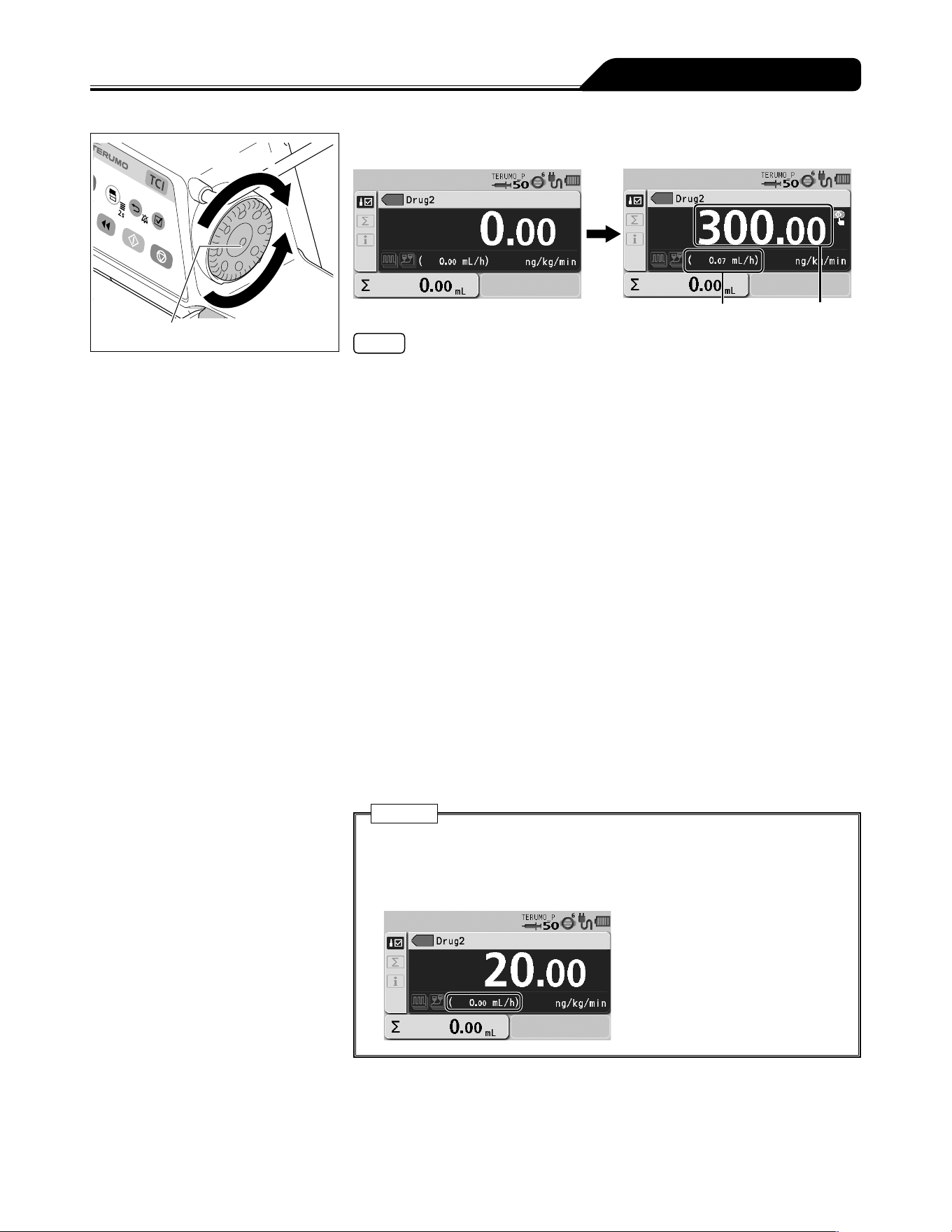
71
Other Operation Procedures
Increases value
Dial
Decreases
value
9) Turn the Dial to adjust the dosage.
Flow rate (mL/h) Dosage rate
Notes
The range of the dosage rate is as follows:
Dose unit = mL/h :
0.01 to 150.00 mL/h (when using syringe of 5 mL)
0.01 to 300.00 mL/h (when using syringe of 10 mL, 20 mL, 30 mL)
0.01 to 1200.00 mL/h (when using syringe of 50/60 mL)
Dose unit = other than mL/h : 0.01 to 999.00
Follow the specified range if the flow rate range is specified for the drug library
registration. The available ranges of two types are shown below. (For details about
how to set, see the dedicated editing software (TERUFUSION Drug Library Manager
or TERUFUSION Software Package).)
- Soft limit
If the flow rate reaches the soft limit of the lower limit or the soft limit of the
upper limit, the Soft lower limit reached, Override? or Soft upper limit
reached, Override? confirmation message is displayed on the LCD. Press the
Confirmation switch to override the upper or lower limit. When the upper or lower
limit is overridden, the flow rate value turns orange.
- Hard limit
If the flow rate reaches the hard limit of the lower limit or the hard limit of the
upper limit, the This is the hard lower limit or This is the hard upper limit
confirmation message is displayed on the LCD. Even if the Confirmation switch
is pressed, the upper or lower limit cannot be overridden.
When a dose unit other than mL/h is selected, the flow rate (mL/h) is automatically
calculated from the specified amount, solution, weight and dosage rate, and
displayed in the flow rate display.
Caution
If the calculation of flow rate (mL/h) is outside of the setting range*,
0.00 mL/h or -----.-- mL/h is displayed and solution delivery does not start
even if the Start switch is pressed. Make the setting again within the flow rate
setting range.
* For details about the flow rate setting range, see [Notes] above or
Specifications on page 146.
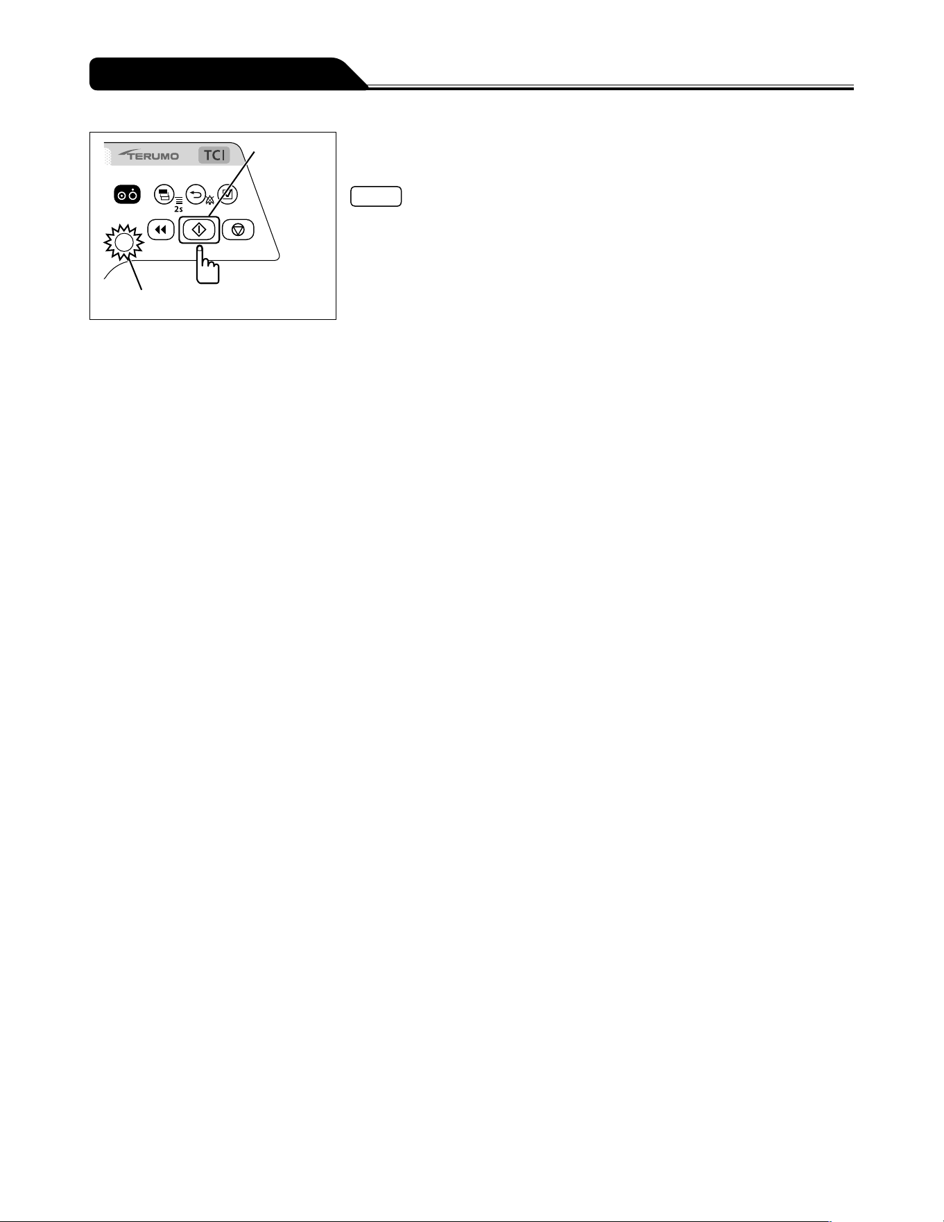
72
Other Operation Procedures
Start switch
Operation indicator (green flashing)
10) Check the flow rate setting and press the Start switch to
start solution delivery.
Notes
The operation indicator flashes green.
The volume delivered increases.
Even after the setting is completed, the TCI mode select screen appears when the
power is turned off and on again.
The amount and solution are re-set when the drug library has been changed or the
power is turned off.
The set weight is re-set when the power is turned off.
Change the dose mode from mL/h to another mode in drug library during solution
delivery.

73
Other Operation Procedures
Setting Special Functions
The following settings are selectable by changing the internal settings of this product. Taking account of a subsequent impact on
product performance, contact TERUMO trained service technicians.
Setting item Description of function
VTBI setting Allows you to set the VTBI. (For details, see page 56.)
VTBI time setting Allows you to set the time limit. (For details, see page 57.)
Setting dial acceleration function Rotating the Dial while pressing the Stop switch accelerates the setting rate to set items such
as the flow rate. This function is not available during solution delivery. Pressing the Stop
switch stops the solution delivery.
Flow rate and VTBI: change the rate to 100-step increments
Date and time: change the rate to hour and month
History and library: change the rate to page feeding
Syringe brand setting The syringe brand can be selected after the power is turned on and the syringe installation
has finished.
Flow rate range setting function A
(Soft limits)
Flow rate range setting function B
(Hard limits)
Sets the limitation of the flow rate in 2 levels; the soft limit (can be exceeded after
confirmation) and the hard limit (cannot be exceeded).
When setting the flow rate over the soft limit, the flow rate will be displayed in orange.
When the drug library mode or body weight dose mode (μg/kg/min, mg/kg/h, or
mg/kg/h+DIPRIVAN) is selected, the flow rate range setting function is not available.
(See page 66.)
Change the Nearly Empty alarm
setting
Allows you to set the Nearly Empty alarm position based on the time before the syringe is
empty.
Change the KVO flow rate Allows you to set the KVO flow rate within the range of 0.10 to 3.00 mL/h.
Hands Free Bolus setting When bolus volume and bolus time are set, flow rate is calculated and the bolus infusion is
available. (For details, see page 88.)
Volume delivered unit select
function
In the case of mass system dose mode, the unit for volume delivered or VTBI can be
changed from volume (mL) to mass (g).
Alarm melody select function Changes the alarm melody from Pattern 1 to Pattern 2.
The default setting is Pattern 1.
Night mode setting If the device is left non-operated for 30 seconds between 21:00 to 5:00 (customizable), the
brightness can be automatically lowered by two levels (customizable).
Change the standby duration Up to 24 hours with 10 minute intervals.
Dose mode select function The dose mode can be selected among mL/h, μg/kg/min, mg/kg/h, mg/kg/h+DIPRIVAN, TCI,
and drug library.
Start-up dose mode select
function
The initial dose mode after the power is turned on can be selected.
Select from mL/h, μg/kg/min, mg/kg/h, mg/kg/h+DIPRIVAN, TCI, and drug library.
Dilution setting function by
amount and solution
Selects how to specify the dilution from either Dilution or Amount/Solution.
Micro notation select function Switches the dose unit from μ to mc.
ON: mc, OFF: μ
Selecting dose mode during the
solution delivery function
Change the dose mode from mL/h to another dose mode (except TCI) during solution
delivery.
The flow rate setting and volume delivered in the mL/h mode are retained after the dose
mode is changed.
If the flow rate (mL/h) is smaller than the lower limit or bigger than the upper limit of the
hard limit in the setting value of the drug library etc., this function is not available.
Purge volume upper limit setting
function
The upper limit of purge volume can be set. The purging stops when the set upper limit is
reached.
Bolus volume upper limit setting
function
When the Hands On Bolus function is enabled, the upper limit of bolus volume can be set.
Bolus stops when the set upper limit is reached.
Menu1 (User mode1) shortcut
function to dose mode
Enable to display the dose mode select display by pressing and holding the Display select
switch for 2 seconds or more.
ON: Displays the dose mode select screen.
OFF: Displays the menu 1 screen.

74
Other Operation Procedures
Setting item Description of function
Set value memory function Saves the current set values (e.g. flow rate, VTBI, dosage and weight) before the power is
turned off.
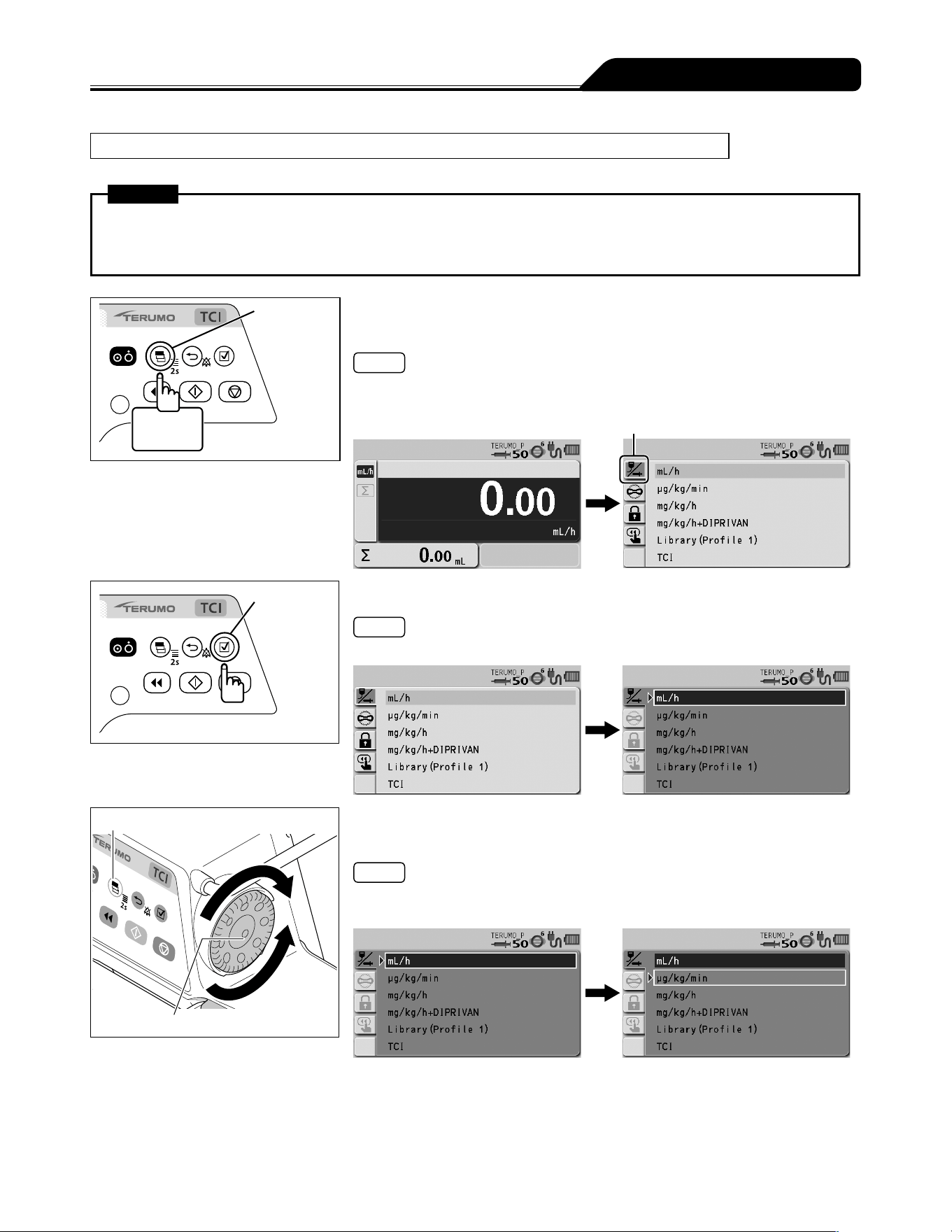
75
Other Operation Procedures
Selecting Dose Mode (Weight Mode) (except TCI) (Default: disabled)
The dose unit setting can be selected.
Warning
Be sure to select the mg/kg/h+DIPRIVAN mode when using a Diprivan pre-filled syringe for general anesthetics or
sedation. Using the dose modes other than mg/kg/h+DIPRIVAN may cause errors in the flow rate accuracy and alarm
function. Read the instruction manual supplied with drugs before using them.
Display
select switch
2 seconds
or more
1) Press and hold the Display select switch for 2 seconds or
more while the solution delivery is stopped.
Note
The menu 1 screen is displayed and then the dose mode select (Dose) display
appears.
Dose mode select tab
Confirmation
switch
2) Press the Confirmation switch.
Note
The existing dose mode (light blue) changes to the selected status (dark blue).
Display select switch
Dial
3) Turn the Dial or press the Display select switch to select
μg/kg/min, mg/kg/h, or mg/kg/h+DIPRIVAN.
Notes
Turning the Dial or pressing the Display select switch moves the white frame.
Select mL/h to return to the default setting.
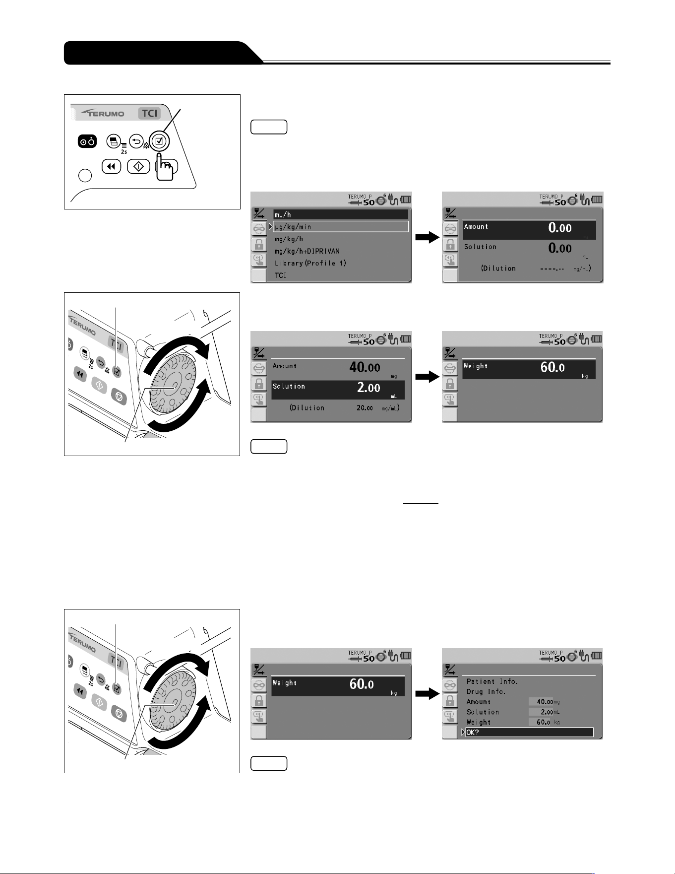
76
Other Operation Procedures
Confirmation
switch
4) Press the Confirmation switch.
Notes
When μg/kg/min or mg/kg/h is selected: The input screen of amount and solution
appears.
When mg/kg/h+DIPRIVAN is selected: The input screen of body weight appears
since dilution is fixed to 10 mg/mL. Go to step 6.
Confirmation switch
Increases value
Dial
Decreases
value
5) Use the Dial to adjust the value of amount and solution, and
press the Confirmation switch.
Notes
The amount and solution can be set within the range below.
Amount (drug amount): 0.01 to 999.00 mg*
Solution (solution amount): 0.01 to 999.00 mL*
*
Setting range of the dilution =
Amount
: 0.01 to 999.00 mg/mL
Solution
If you want to set by Dilution, contact TERUMO trained service technicians.
If the Confirmation switch is pressed after setting the drug amount, the input area
moves to Solution.
When the Confirmation switch is pressed after setting the solution amount, the
input screen of body weight appears.
When the Back/Mute switch is pressed, the parameter input is cancelled and the
screen returns to the previous status.
Confirmation switch
Increases value
Dial
Decreases
value
6) Use the Dial to adjust the value of weight, and press the
Confirmation switch.
Notes
Weight can be set within the range of 0.1 to 300.0 kg.
Pressing the Confirmation switch displays the parameter confirmation screen.
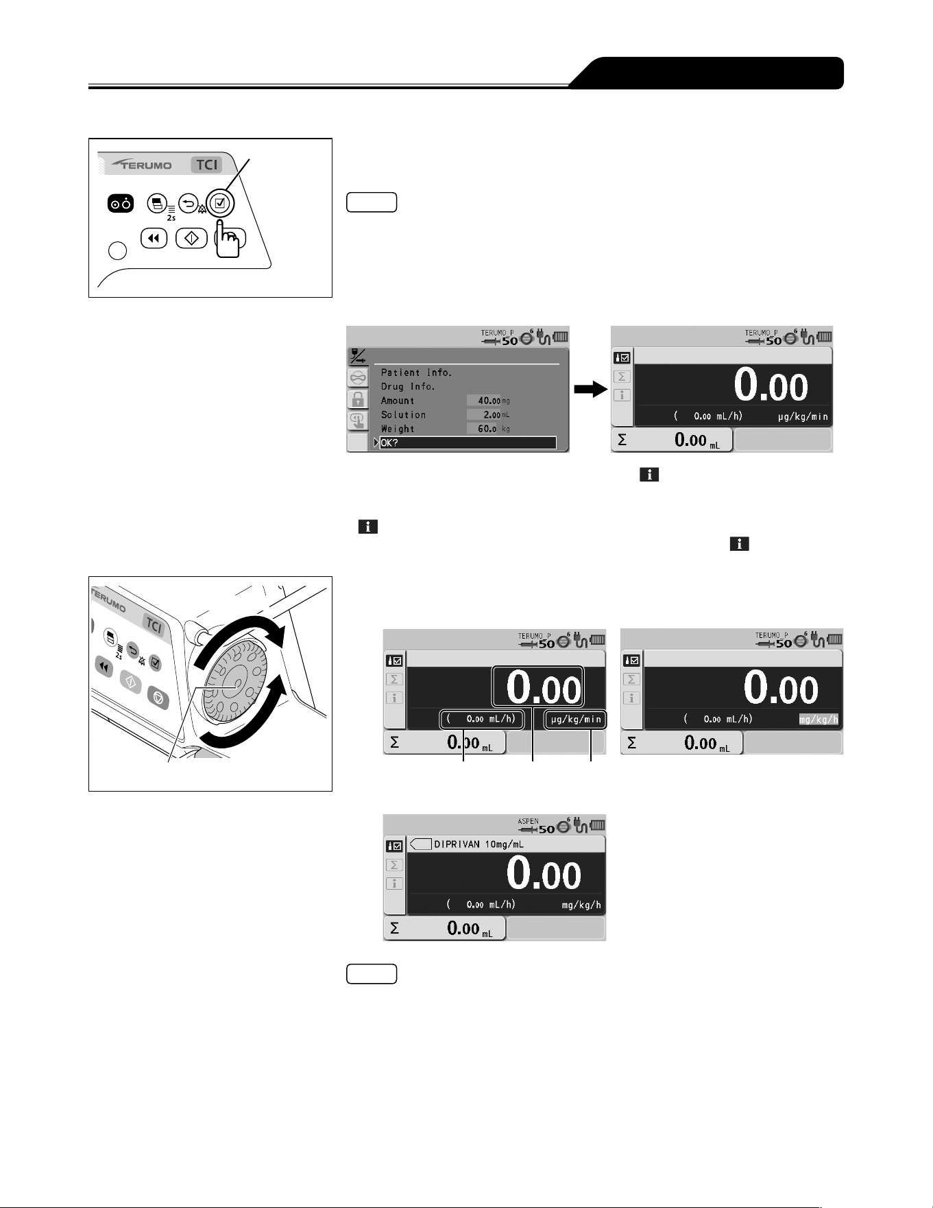
77
Other Operation Procedures
Confirmation
switch
7) Check the parameter value and that OK? is selected,
press the Confirmation switch.
Notes
Parameter changes can be identified by the change in background colour on the
parameter confirmation screen.
When the Back/Mute switch is pressed on the parameter confirmation screen, the
parameter input is cancelled and the screen returns to that of step 3.
Parameter values can be changed from the parameter confirmation screen.
When the Confirmation switch is pressed, the flow rate display appears.
Press the Display select switch to select info tab . The setting information
appears.
Parameter values can be changed from the screen displayed by selecting info tab
.
For details about the contents that can be checked from info tab
, see
page 69.
Increases value
Dial
Decreases
value
8) Turn the Dial to adjust the dosage.
For example: μg/kg/min For example: mg/kg/h
Flow rate Dose rate Dose unit
For example: mg/kg/h+DIPRIVAN
Notes
The dosage can be set within the range below.
Dose unit = μg/kg/min: 0.01 to 999.00
Dose unit = mg/kg/h: 0.01 to 999.00
Based on amount, solution, weight, dosage, the flow rate (mL/h) is automatically
calculated, and the flow rate display shows the result.
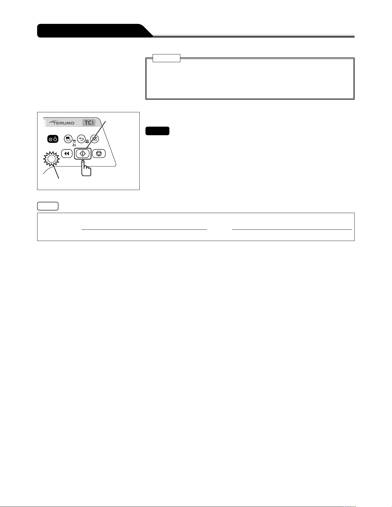
78
Other Operation Procedures
Caution
If the calculation of flow rate (mL/h) is outside of the setting range*,
0.00 mL/h or -----.-- mL/h is displayed and solution delivery does not start
even if the Start switch is pressed. Make the setting again within the flow rate
setting range.
* For details about the flow rate setting range, see page 146 .
Start switch
Operation indicator (green flashing)
9) Press the Start switch to start solution delivery.
Checks
The set value is correct.
The operation indicator flashes green.
The volume delivered increases.
Notes
Calculation Formula of Flow Rate
Amount (mg) X 1000
(
*
2)
����������������������������������������������������������
Amount (mg)
��������������������X������������������X��������������
������������������
X 60
(
*
1)
��
*
1
: Coefficient to convert minute (min.) to hour (h)
*
2
: Coefficient to convert mg to μg
Switching the dose unit or re-selecting the same dose unit changes the values of flow rate, dosage, amount, solution, and
volume delivered to 0.
Even after the setting is completed, the TCI mode select screen appears when the power is turned off and on again.
Patient name, Patient ID, Gender, Age, Height and Weight can be acquired via communication with an external device. For the
setting method, contact TERUMO trained service technicians.

79
See pages 15 and 16 for the menu list.
Notes
While changing the menu settings, pressing the Start switch does not start solution delivery.
Occlusion detection pressure, keypad lock, bolus, advanced dose mode and combination dose mode on Menu 1 can be selected
or set during solution delivery. Other items are not available.
How to exit menus
Method 1) Press and hold the Display select switch in the menu for 2 seconds or more.
If the setting has not been completed, the setting is cancelled and the display goes to the flow rate screen.
Method 2) Press the Back/Mute switch repeatedly.
If the setting has not been completed, the setting is cancelled and the display goes back to the previous screen.
If an alarm occurs before pressing the Confirmation switch or the Back/Mute switch while setting the menu, any changes will
return to the settings before the alarm was issued.
Time before the screen returns to the flow rate screen.
(1) Level in which menu tab has been selected:
Goes back to the flow rate screen after 10 seconds of no operation.
(2) Levels on and after which menu tab has been specified:
Goes back to the flow rate screen after 2 minutes of no operation.
Changing Settings on the Menu
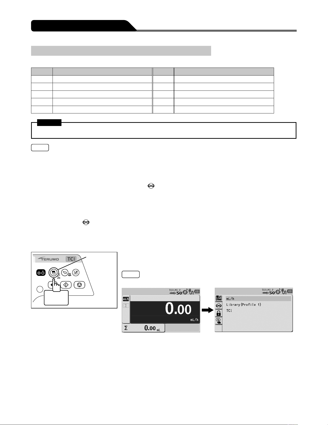
80
Changing Settings on the Menu
Occlusion Detection Pressure
The occlusion detection pressure can be set in 10 levels.
Setting Occlusion detection pressure Setting Occlusion detection pressure
1 ± 10 kPa 6 ± 70 kPa (Default)
2 ± 20 kPa 7 ± 90 kPa
3 ± 30 kPa 8 ± 100 kPa
4 ± 40 kPa 9 ± 110 kPa
5 ± 50 kPa 10 ± 120 kPa
Warning
After the occlusion detection pressure is selected, check that the setting has been adjusted correctly.
Notes
If using on Level 10, the pressure of an infusion line increases at occlusion, possibly resulting in the syringe connection etc.
being disconnected. Periodically check that the connection of the infusion line is secured.
If using on Level 1, an Occlusion alarm is frequently issued, especially when using a drug solution with high viscosity, possibly
resulting in solution delivery being interrupted. In such cases, review the set value of the occlusion pressure by using the graph
of the history of occlusion pressure value as a guide.
When an Occlusion alarm is issued, the occlusion icon
may not reach the orange level (more than 75%) for the following
reasons:
(1) When the bolus reduction function is activated in order to mitigate the occlusion status
(2) When the syringe is fully pressed (stopped after the Nearly Empty alarm or an internal pressure equivalent to the set Level
4 occlusion pressure value is detected)
* After an Occlusion alarm is issued internal pressure may build up even if the occlusion icon has not turned orange.
Use the occlusion icon
as follows:
(1) To check the in-line pressure when using a small syringe and a small diameter administration set and/or infusing a highly
viscous solution.
(2) To make sure the infusion line has been opened.
Display
select switch
2 seconds
or more
1) Press and hold the Display select switch for 2 seconds or
more.
Note
The menu 1 screen is displayed and the icons are ready to be selected.
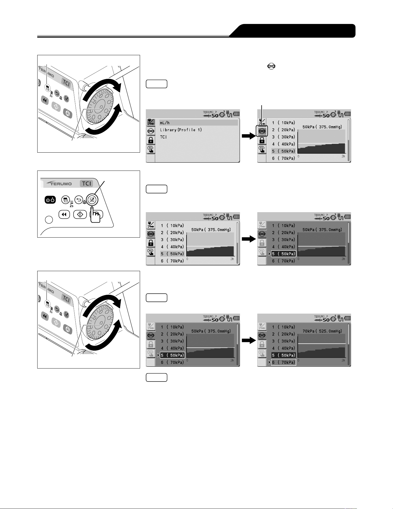
81
Changing Settings on the Menu
Display select switch
Dial
2) Turn the Dial or press the Display select switch to select the
occlusion detection pressure tab
.
Note
The occlusion detection pressure setting display has appeared.
Occlusion detection pressure tab
Confirmation
switch
3) Press the Confirmation switch.
Note
The existing occlusion detection pressure (light blue) changes to the selected
status (dark blue).
Display select switch
Dial
4) Turn the Dial or press the Display select switch to select
occlusion detection pressure.
Note
Turning the Dial or pressing the Display select switch moves the white frame.
Notes
Left side : Occlusion detection pressure setting
Right side : Occlusion history graph
In the graph, the horizontal axis indicates the time and the vertical axis indicates
the occlusion detection pressure.
Displays a graph of the history of occlusion pressure value in the past 2 hours.
The horizontal line in the graph indicates the currently selected occlusion
detection pressure. (This history is deleted when the power is turned off.)
The graph is updated every 2 minutes.
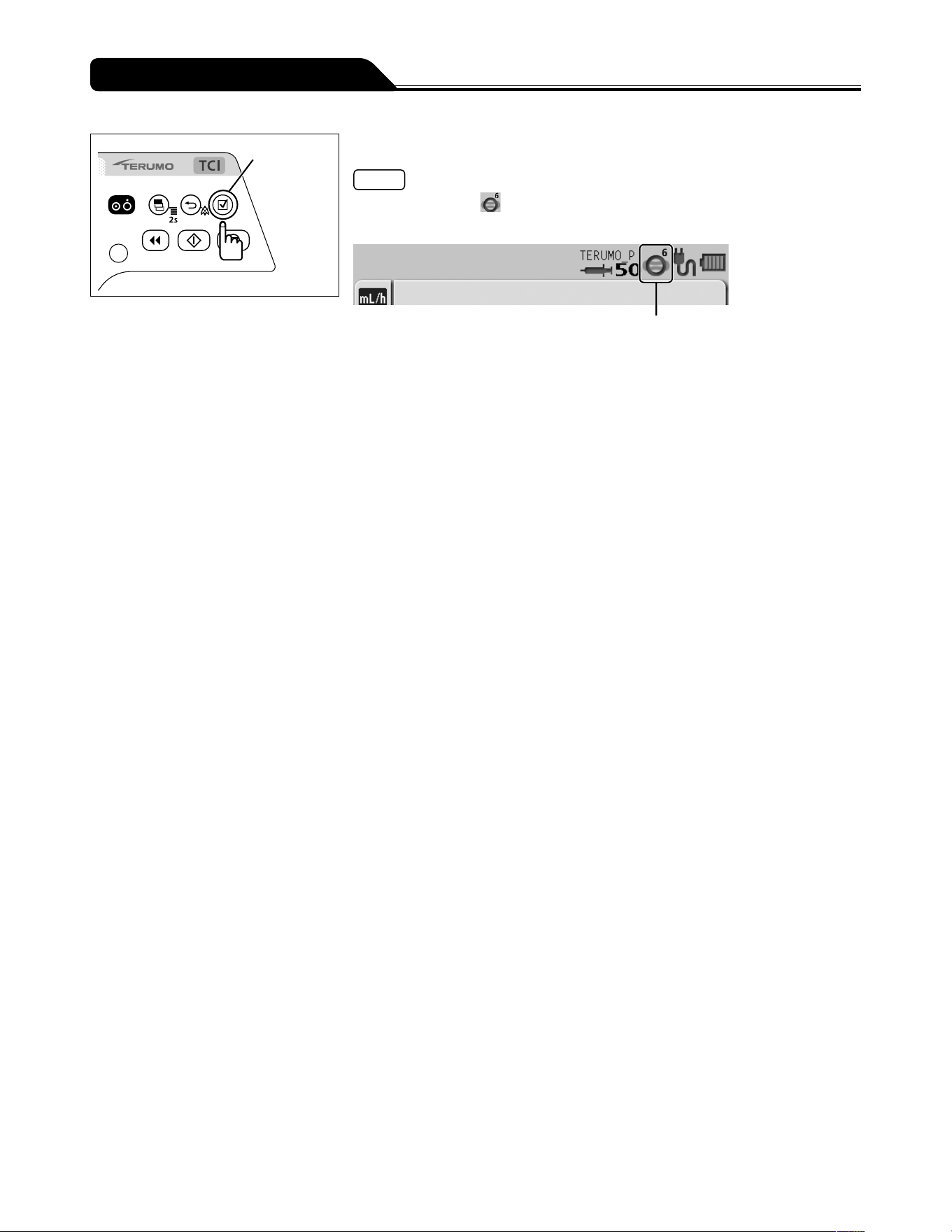
82
Changing Settings on the Menu
Confirmation
switch
5) Press the Confirmation switch to confirm the selection.
Note
The occlusion icon in the status icon display shows the selected occlusion
detection pressure.
Occlusion icon
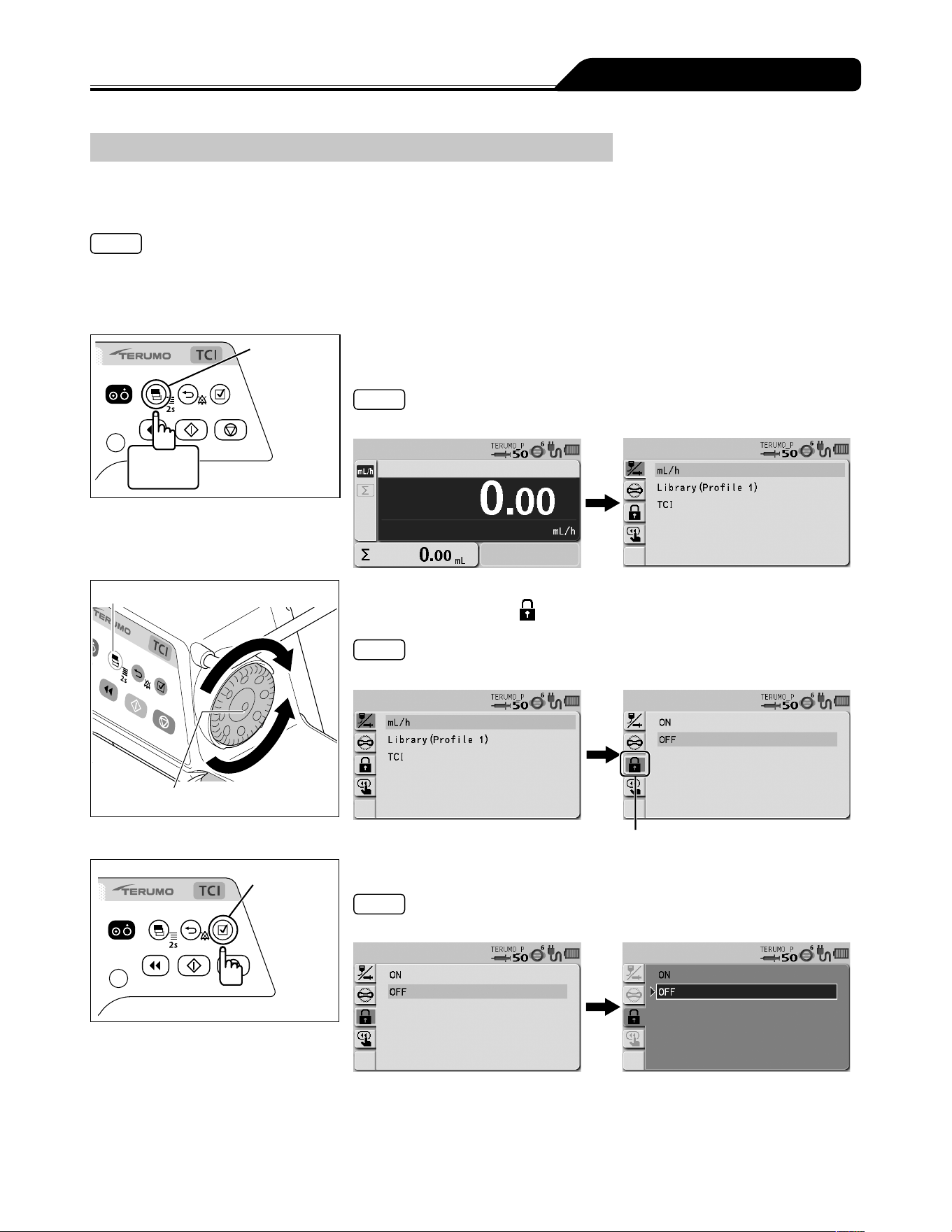
83
Changing Settings on the Menu
Keypad Lock Function
The panel operation can be disabled to prevent inadvertent operation while solution delivery is stopped or in-progress.
To enable the keypad lock
Notes
Even if the keypad lock is enabled, the Power switch and the Start switch can be operated. The keypad lock release operation
(press and hold the Back/Mute switch for 2 seconds or more) is also allowed when the keypad lock is enabled.
Even if the Stop switch is pressed, the solution delivery cannot be stopped when the keypad lock is enabled. To stop solution
delivery, first release the keypad lock.
Display
select switch
2 seconds
or more
1) Press and hold the Display select switch for 2 seconds or
more.
Note
The menu 1 screen is displayed and the icons are ready to be selected.
Display select switch
Dial
2) Turn the Dial or press the Display select switch to select the
keypad lock tab
.
Note
The keypad lock ON/OFF setting display has appeared.
Keypad lock tab
Confirmation
switch
3) Press the Confirmation switch.
Note
The existing setting (light blue) changes to the selected status (dark blue).
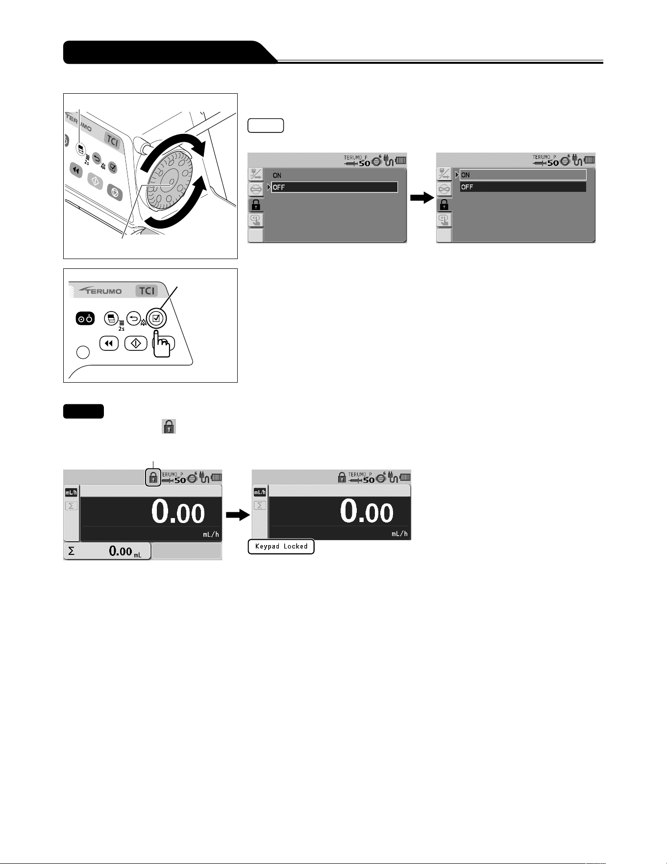
84
Changing Settings on the Menu
Display select switch
Dial
4) Turn the Dial or press the Display select switch to select ON.
Note
Turning the Dial or pressing the Display select switch moves the white frame.
Confirmation
switch
5) Press the Confirmation switch to confirm the selection.
Checks
The keypad lock icon
appears in the status icon display.
The keypad lock message appears when the Dial or a switch (other than the Power switch and Start switch) is operated.
Keypad lock icon
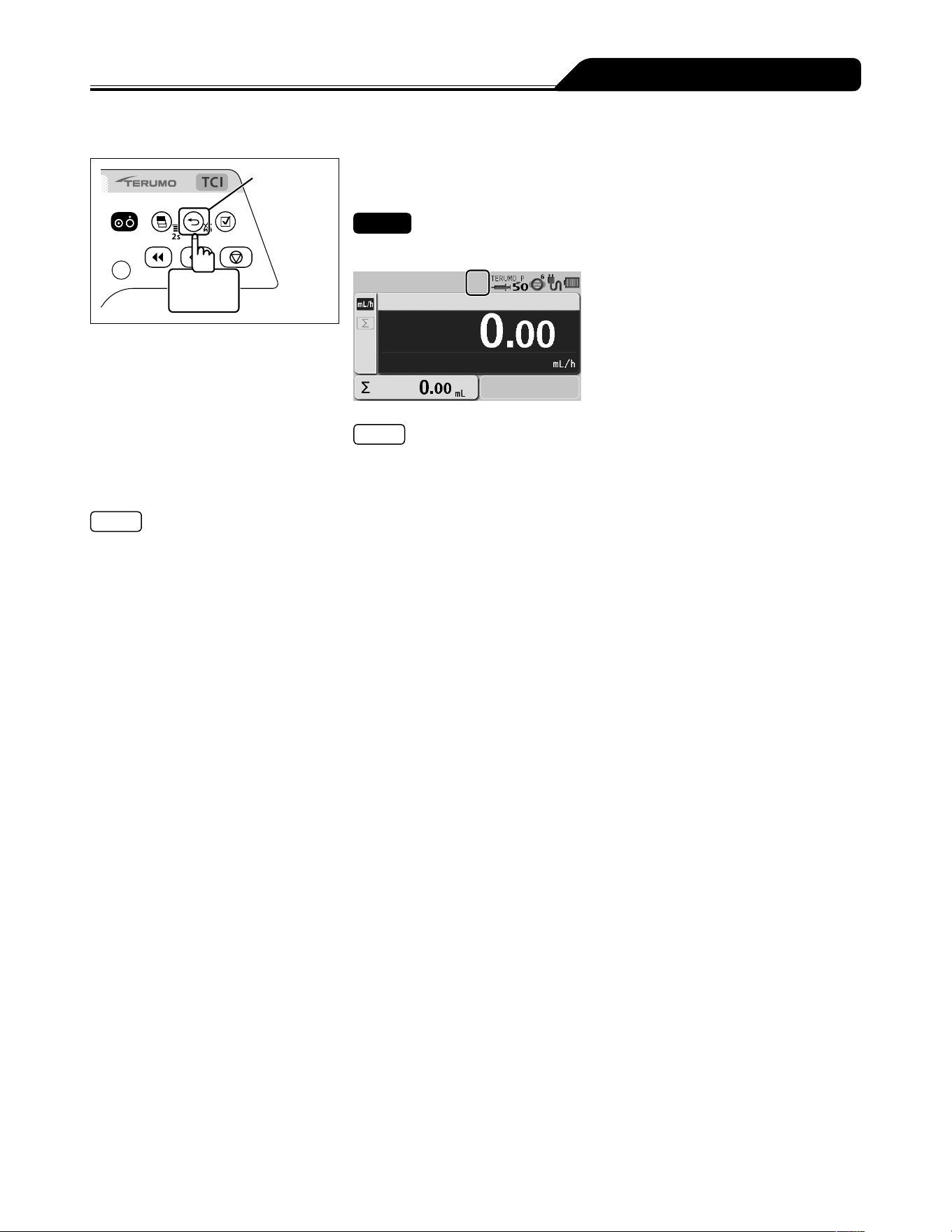
85
Changing Settings on the Menu
To release the keypad lock
Back/Mute
switch
2 seconds
or more
Press and hold the Back/Mute switch for 2 seconds or more
to release the keypad lock.
Check
The keypad lock icon has disappeared.
Note
Even while the keypad lock is on, the Power switch and the Start switch are
available.
Note
In the case of a high-priority alarm, the keypad lock function is automatically switched off.
However, the keypad lock will not be disabled by Start Reminder.
(If the status allows startup, the solution delivery can be started while the keypad lock is enabled.)
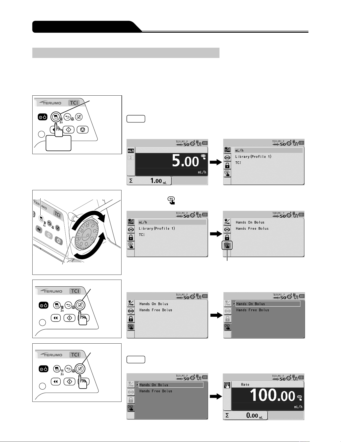
86
Changing Settings on the Menu
Bolus (except the TCI mode)
The bolus can be performed when solution delivery is in progress or when stopped. There are two ways for selecting bolus either
through the menu or pressing the Purge switch while pressing the Back/Mute switch. In addition, every time the Purge switch is
pressed while Back/Mute switch is pressed, you can switch between the Hands On Bolus and Hands Free Bolus.
Hands On Bolus
Display
select switch
2 seconds
or more
1) Press and hold the Display select switch for 2 seconds or
more.
Notes
The menu 1 screen is displayed and the icons are ready to be selected.
VTBI needs to be set before setting this function if VTBI has been enabled.
Display select switch
Dial
2) Turn the Dial or press the Display select switch to select the
bolus tab
.
Bolus tab
Confirmation
switch
3) Press the Confirmation switch.
Confirmation
switch
4) Press the Confirmation switch to confirm the selection.
Note
The current Bolus flow rate setting screen appears.
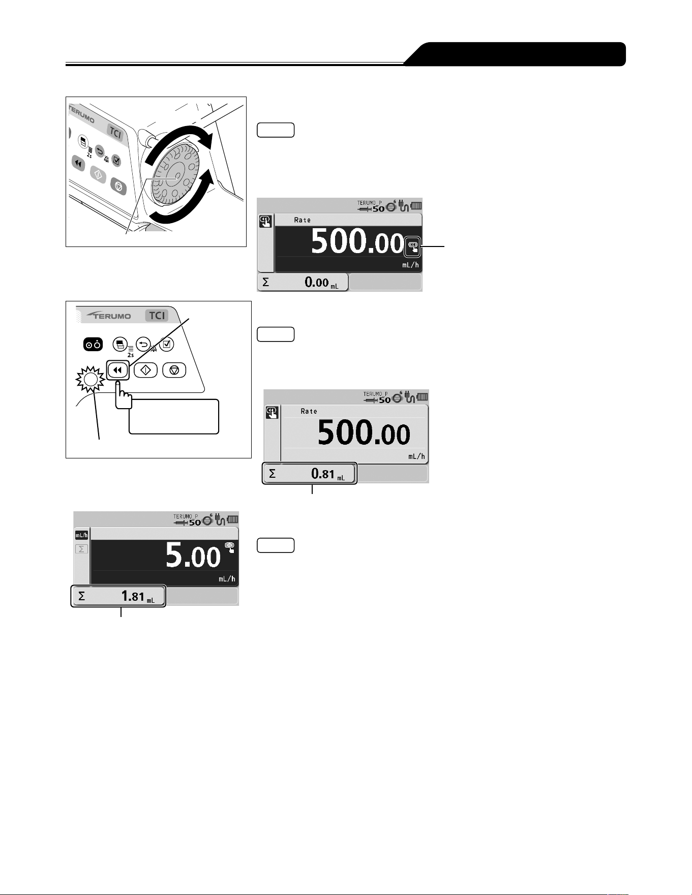
87
Changing Settings on the Menu
Increases value
Dial
Decreases
value
5) Turn the Dial to set the Bolus flow rate.
Note
The Bolus flow rate can be set by 100 mL/h in the following value range.
- When using syringe of 5 mL: 100 mL/h
- When using syringe of 10, 20, 30 mL: 100 mL/h to 300 mL/h
- When using syringe of 50/60 mL: 100 mL/h to 1200 mL/h
Ready for bolus icon
Purge switch
Bolus while being
pressed
Operation indicator (green flashing)
6) Press and hold the Purge switch to start the bolus.
Notes
The operation indicator flashes green.
The bolus volume delivered increases.
The buzzer sounds during solution delivery.
Bolus volume delivered
Volume delivered
7) Release the Purge switch to stop the bolus.
Notes
If the Purge switch is pressed again within 1.5 seconds after being released,
Hands On Bolus continues and the bolus volume delivered display is maintained.
If exceeding 1.5 seconds after the Purge switch has been released, the screen
returns to the flow rate screen.
While the Purge switch is pressed, the volume delivered display shows the bolus
volume delivered. When releasing the Purge switch, the display shows the sum
of the volume delivered. (The bolus volume delivered is added to the sum of the
volume delivered.)
When bolus infusion during solution delivery is completed, solution delivery starts
at the same flow rate as before the bolus infusion.
A Completion alarm occurs if the volume delivered reaches the VTBI when bolus
infusion is used during solution delivery. The solution delivery continues at the flow
rate of KVO (Keep Vein Open).
The dose setting (flow rate) of Hands On Bolus remains set, and is used when the
next Hands On Bolus is performed, until the power is turned off or the dose mode
is switched.
The upper limit of bolus volume can be set. To change this, contact TERUMO
trained service technicians.
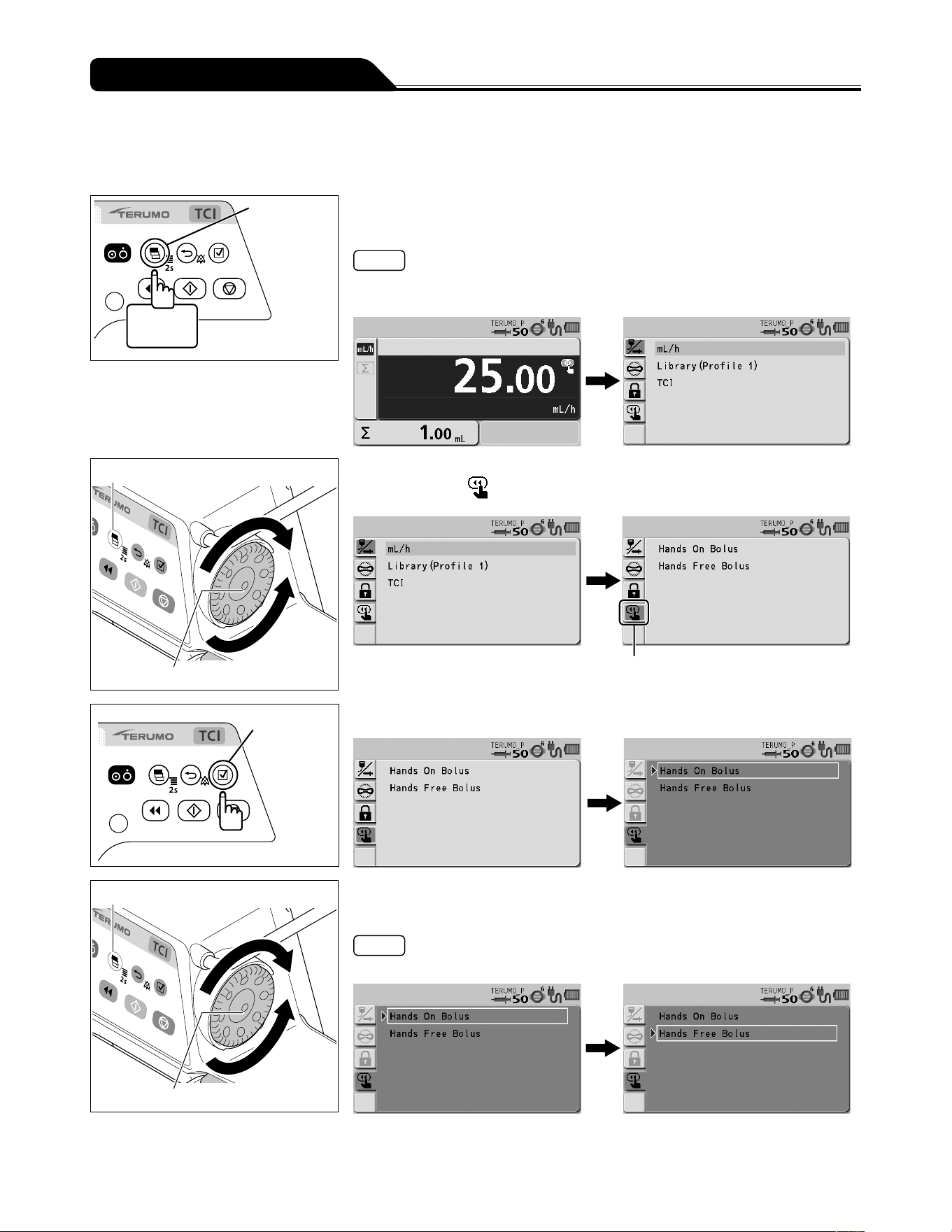
88
Changing Settings on the Menu
Hands Free Bolus
Setting the Bolus VTBI and Bolus VTBI time enables automatic calculation of the Bolus flow rate (mL/h) and execution of bolus
infusion without holding down the Purge switch. (Hands Free Bolus function)
Display
select switch
2 seconds
or more
1) Press and hold the Display select switch for 2 seconds or
more.
Notes
The menu 1 screen is displayed and the icons are ready to be selected.
VTBI needs to be set before setting this function if VTBI has been enabled.
Display select switch
Dial
2) Turn the Dial or press the Display select switch to select the
bolus tab
.
Bolus tab
Confirmation
switch
3) Press the Confirmation switch.
Display select switch
Dial
4) Turn the Dial or press the Display select switch to select the
Hands Free Bolus.
Note
Turning the Dial or pressing the Display select switch moves the white frame.
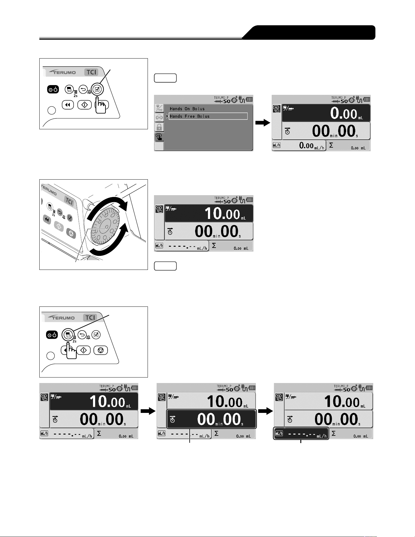
89
Changing Settings on the Menu
Confirmation
switch
5) Press the Confirmation switch.
Notes
The bolus setting display appears.
When the flow rate screen is displayed, the Hands Free Bolus screen can be
displayed by pressing and holding the Back/Mute switch and pressing the Purge
switch twice.
Increases value
Dial
Decreases
value
6) Turn the Dial to set the Bolus VTBI.
Notes
The Bolus VTBI can be set within the range below.
VTBI: 0.01 to 999.00
The Bolus VTBI must be set within the values obtained by subtracting the volume
delivered from the VTBI.
Display
select switch
7) Press the Display select switch to select the Bolus VTBI
time or the Bolus flow rate.
Bolus flow rate
Bolus VTBI time

90
Changing Settings on the Menu
Increases value
Dial
Decreases
value
8) Turn the Dial to set the Bolus VTBI time or the Bolus flow
rate.
Notes
The Bolus VTBI time or the Bolus flow rate (mL/h) has been calculated from the
Bolus VTBI, and is displayed.
The ready for bolus icon is displayed.
Ready for bolus icon
Bolus VTBI time
Bolus flow rate
The Bolus flow rate can be set within the range of the following values.
Setting range:
0.01 to 150.00 mL/h (when using syringe of 5 mL)
0.01 to 300.00 mL/h (when using syringe of 10 mL, 20 mL, 30 mL)
0.01 to 1200.00 mL/h (when using syringe of 50/60 mL)
Step:
0.01 mL/h step (0.01 to 10.00 mL/h)
0.10 mL/h step (10.00 to 100.00 mL/h)
1.00 mL/h step (100.00 to 1200.00 mL/h)
The Bolus VTBI time can be set within the range below.
Bolus VTBI time: 00min01s to 60min00s
Caution
When using the Hands Free Bolus function, the setting cannot take a flow rate (mL/h) calculation result outside the flow
rate setting range, and therefore it should be reconfigured. [----.--] or [0.00] is displayed, not allowing solution delivery.
Purge switch
Operation indicator (green flashing)
9) Press the Purge switch to start the bolus.
Notes
The operation indicator flashes green.
The bolus volume delivered increases.
The alarm melody sounds during solution delivery.
Bolus volume delivered

91
Changing Settings on the Menu
10) The bolus ends when the VTBI is reached.
Check
The screen returns to the flow rate screen when the VTBI has been reached and
the bolus has been completed.
Notes
The volume delivered display area displays the amount of bolus during bolus
infusion, and displays the sum of the amount of bolus and the volume delivered
when the VTBI is attained and the bolus ends.
When bolus infusion during solution delivery is completed, solution delivery
continues at the flow rate before the bolus infusion.
A Completion alarm occurs if the volume delivered reaches the VTBI when bolus
infusion is used during solution delivery. The solution delivery continues at the flow
rate of KVO (Keep Vein Open).
Pressing the Stop switch forcibly stops Hands Free Bolus.

92
Changing Settings on the Menu
Maximum flow rate setting (TCI mode only)
The maximum flow rate can be changed.
Display
select switch
2 seconds
or more
1) Press and hold the Display select switch for 2 seconds or
more.
Confirmation
switch
2) Press the Confirmation switch.
Note
The current setting display turns from light blue to dark blue (selected status).
Display select switch
Dial
3) Turn the Dial or press the Display select switch to select the
‒
TCI Menu.
Note
Turning the Dial or pressing the Display select switch moves the white frame.
Confirmation
switch
4) Press the Confirmation switch.
Notes
The TCI Menu screen appears.
The TCI Menu screen can also be displayed if you turn the Dial or press the
Display select switch in step 2) to select the TCI tab.
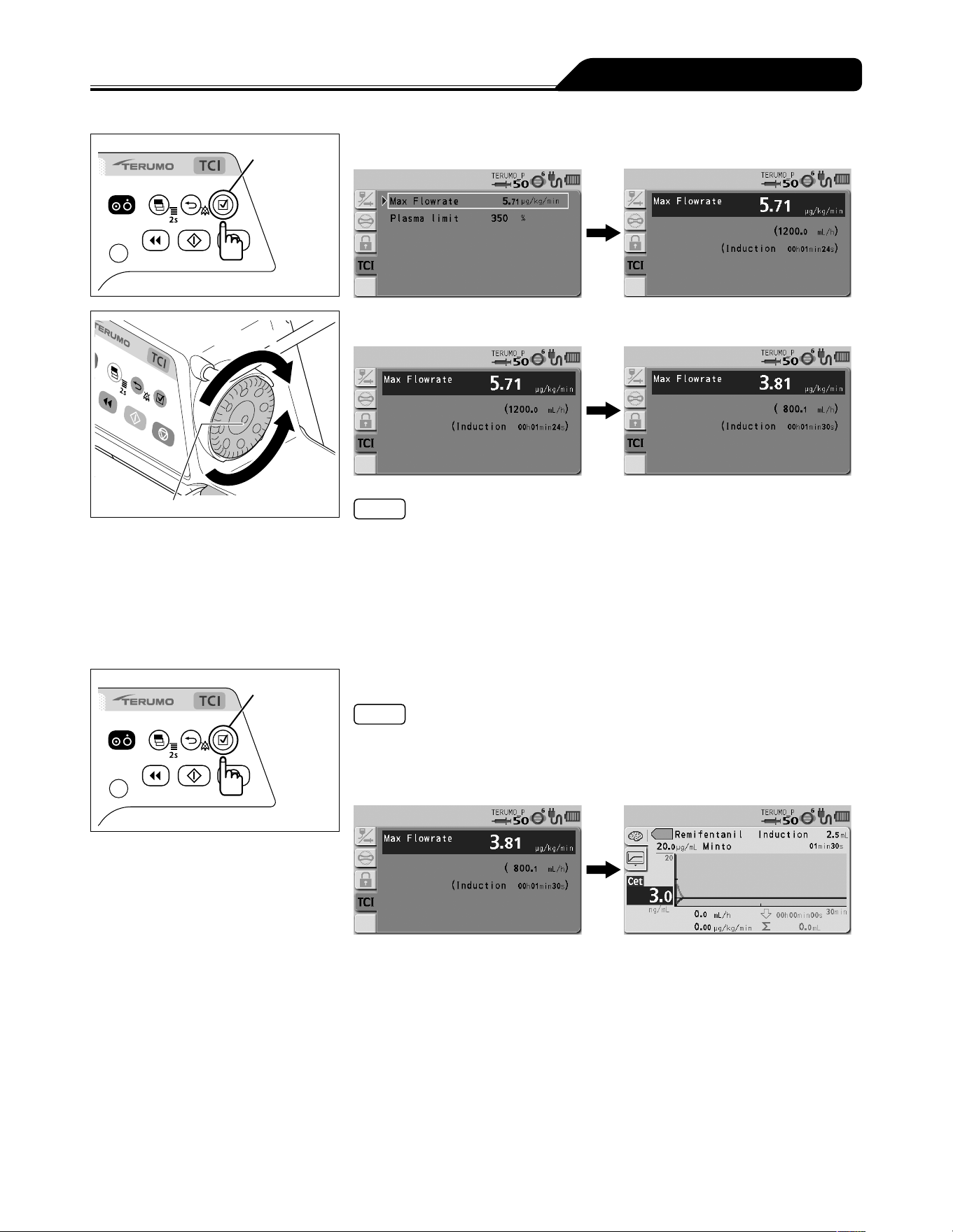
93
Changing Settings on the Menu
Confirmation
switch
5) Press the Confirmation switch.
Increases value
Dial
Decreases
value
6) Turn the Dial to select the maximum flow rate.
Note
The upper limit of flow rate can be set within the range of the following values.
Setting range:
0.01 to 999.00 mg/kg/h (Propofol)
0.01 to 999.00 μg/kg/min (Remifentanil)
Step:
0.01 step (0.01 to 10.00)
0.10 step (10.00 to 100.00)
1.00 step (100.00 to 999.00)
Confirmation
switch
7) Press the Confirmation switch.
Notes
The display returns to the graph screen.
When the maximum flow rate is changed before starting solution delivery, the
indications of the initial infusion dose/time and the prediction lines in the graph will
change accordingly.
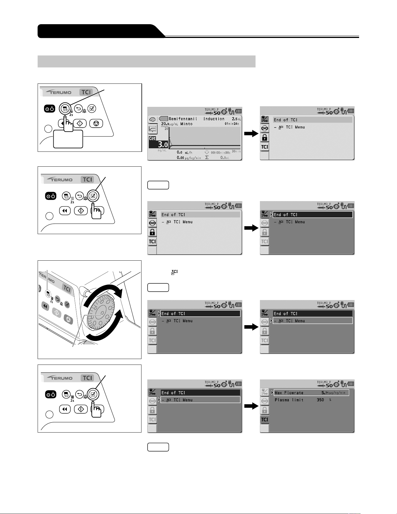
94
Changing Settings on the Menu
Plasma limit setting (TCI mode only)
Before starting solution delivery in effect-site TCI, set the upper limit of plasma concentration for the appropriate level of overshoot.
Display
select switch
2 seconds
or more
1) Press and hold the Display select switch for 2 seconds or
more.
Confirmation
switch
2) Press the Confirmation switch.
Note
The current setting display turns from light blue to dark blue (selected status).
Display select switch
Dial
3) Turn the Dial or press the Display select switch to select the
‒
TCI Menu.
Note
Turning the Dial or pressing the Display select switch moves the white frame.
Confirmation
switch
4) Press the Confirmation switch.
Notes
The TCI Menu screen appears.
The TCI Menu screen can also be displayed if you turn the Dial or press the
Display select switch in step 2) to select the TCI tab.
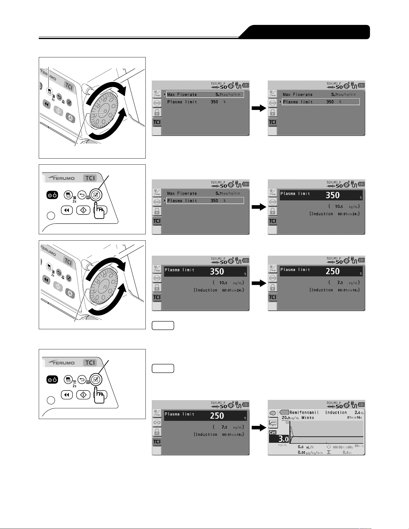
95
Changing Settings on the Menu
Display select switch
Dial
5) Turn the Dial or press the Display select switch to select
Plasma limit.
Confirmation
switch
6) Press the Confirmation switch.
Increases value
Dial
Decreases
value
7) Turn the Dial to set the upper limit of plasma concentration.
Note
The upper limit of plasma concentration can be set within the range of 200 to
350%.
Confirmation
switch
8) Press the Confirmation switch.
Notes
The display returns to the graph screen.
The indications of the initial infusion dose/time and the prediction lines in the graph
will change accordingly.
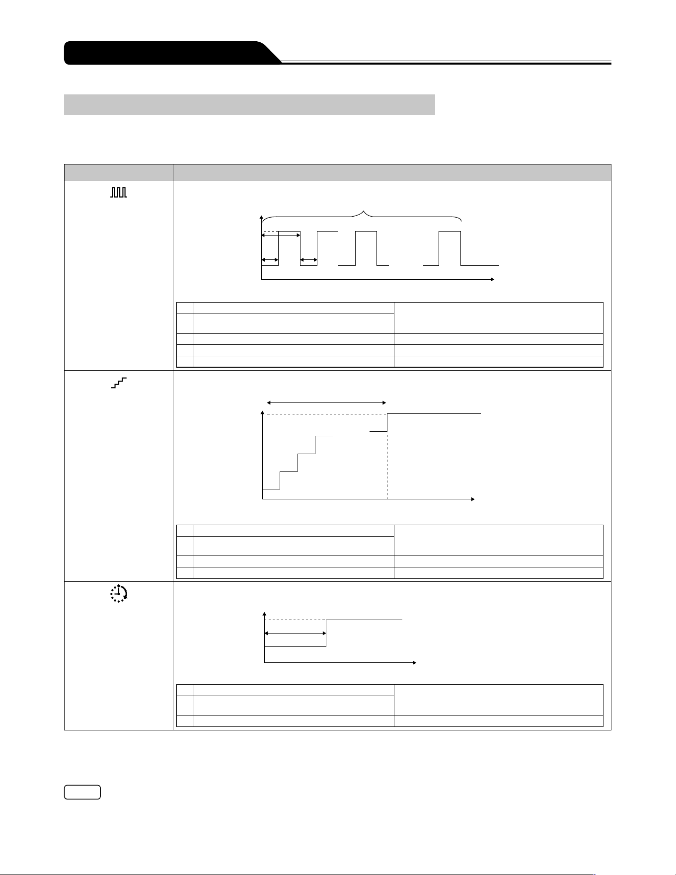
96
Changing Settings on the Menu
Advanced Dose Mode
An advanced dose mode can be selected from the three advanced dose modes in the table below according to the selected drug.
A library should be registered before selecting the advanced mode. Use the dedicated editing software (TERUFUSION Drug
Library Manager or TERUFUSION Software Package) for registration. See page 66 for how to select the library.
Advanced dose mode Details
Interval/Intermittent
Mode
Two specified dosage rates are alternately delivered at regular intervals for the specified number of steps.
. . . . .
5) Number of steps
Flow rate
2) Dosage rate 2
1) Dosage rate 1
3) 1 cycle time
4)
4) Time interval
Dosing time
Input parameters
1) Dosage rate 1 For the dosage rate range, see page 68.
When using an advanced dose mode, 0.00 can
be set for the dosage rate.
2) Dosage rate 2 (Displays: Final Flow Rate)
3) 1 cycle time (Displays: Time/Cycle) 00h01min to 23h59min
4) Time interval (Displays: Time) 00h01min to 23h59min
5) Number of steps (Displays: Number of Steps) 1 to 255 steps
Multi-step Mode
The speed of solution delivery increases or decreases at the specified levels (up to 10 levels).
. . . . .
Flow rate
2) Dosage rate 2
1) Dosage rate 1
4) Number of steps
Dosing time
3) Time
Input parameters
1) Dosage rate 1 For the dosage rate range, see page 68.
When using an advanced dose mode, 0.00 can
be set for the dosage rate.
2) Dosage rate 2 (Displays: Final Flow Rate)
3) Time (Displays: Time to Final Flow Rate) 00h01min to 23h59min
4) Number of steps (Displays: Steps) 1 to 10 steps
Delayed Start Mode
Solution delivery starts after the specified time has elapsed.
Flow rate
2) Dosage rate 2
1) Dosage rate 1
3) Delay Time
Dosing time
Input parameters
1) Dosage rate 1 For the dosage rate range, see page 68.
When using an advanced dose mode, 0.00 can
be set for the dosage rate.
2) Dosage rate 2 (Displays: Final Flow Rate)
3) Delay Time (Displays: Delay Time) 00h01min to 23h59min
Dosage rate 1 can be set in the Dose Rate in the flow rate setting screen.
There is no rule stating which of the volumes between dosage rate 1 and dosage rate 2 should be larger.
If one of the dosage rate 1 or 2 is not set, solution delivery does not start.
The dosage rate must be set within the setting range for each library.
The calculation result of flow rate (mL/h) must be set within the flow rate setting range.
Note
When registering library, determine the range of the dosage rate considering the drug and the dose method. (Depending on the
setting of the dosage rate, the occlusion may occur due to the thrombus formation within the infusion line.)
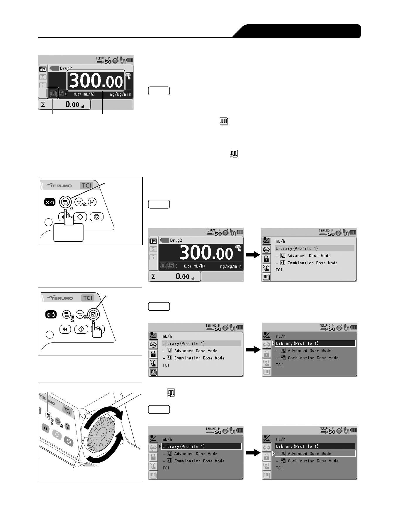
97
Changing Settings on the Menu
Advanced dose
mode icon
Dosage rate 1
1) Follow step 1) to 9) on Selecting Dose Mode (Drug Library)
to select the library name, shown as "Drug2" in the example,
and set the dosage rate 1.
Notes
When using an advanced dose mode, 0.00 can be set for the dosage rate.
See page 66 for how to select the library.
If the selected library has been enabled to accept an advanced dose mode, the
advanced dose mode icon
is displayed on the LCD. If an advanced dose mode
is unacceptable, no icon is displayed.
There are two procedures to select the advanced dose mode:
One is selecting the Advanced dose mode on the menu tab of the menu 1 screen.
The other one is selecting the
Advanced Dose Mode displayed below
Library in the dose mode select display, as described in the following steps.
If you perform the former procedure, go to step 6.
Display
select switch
2 seconds
or more
2) Press and hold the Display select switch for 2 seconds or
more.
Note
The menu 1 screen is displayed and then the dose mode select (Dose) display
appears.
Confirmation
switch
3) Press the Confirmation switch.
Note
Library (light blue) changes to the selected status (dark blue).
Display select switch
Dial
4) Turn the Dial or press the Display select switch to select the
Advanced Dose Mode displayed below Library.
Note
Turning the Dial or pressing the Display select switch moves the white frame.
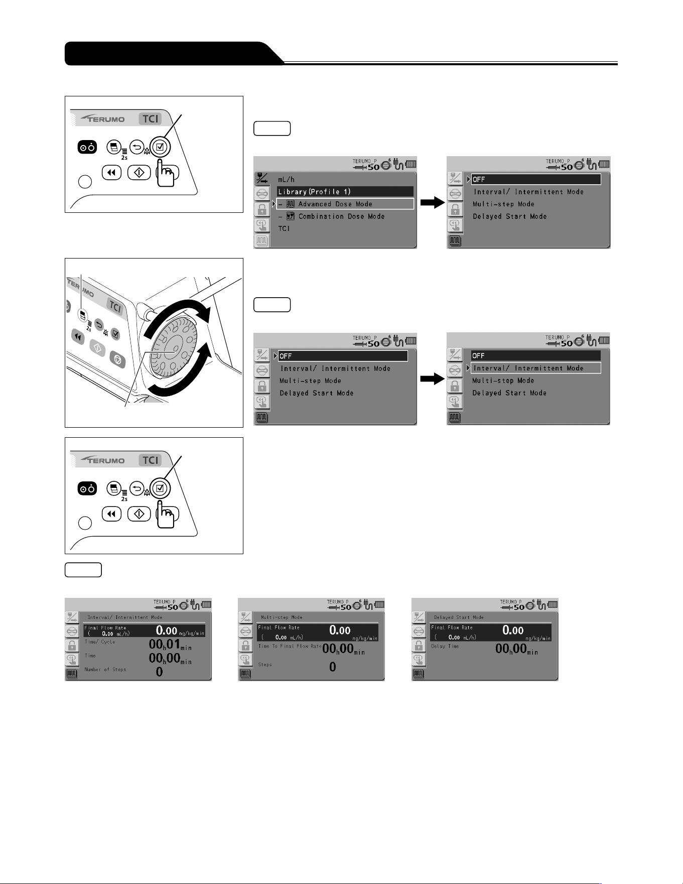
98
Changing Settings on the Menu
Confirmation
switch
5) Press the Confirmation switch.
Note
The available advanced dose modes are displayed.
Display select switch
Dial
6) Turn the Dial or press the Display select switch to select the
advanced dose mode.
Note
Turning the Dial or pressing the Display select switch moves the white frame.
Confirmation
switch
7) Press the Confirmation switch.
Note
The screen changes to the parameter input display.
Interval/Intermittent Mode Multi-step Mode Delayed Start Mode
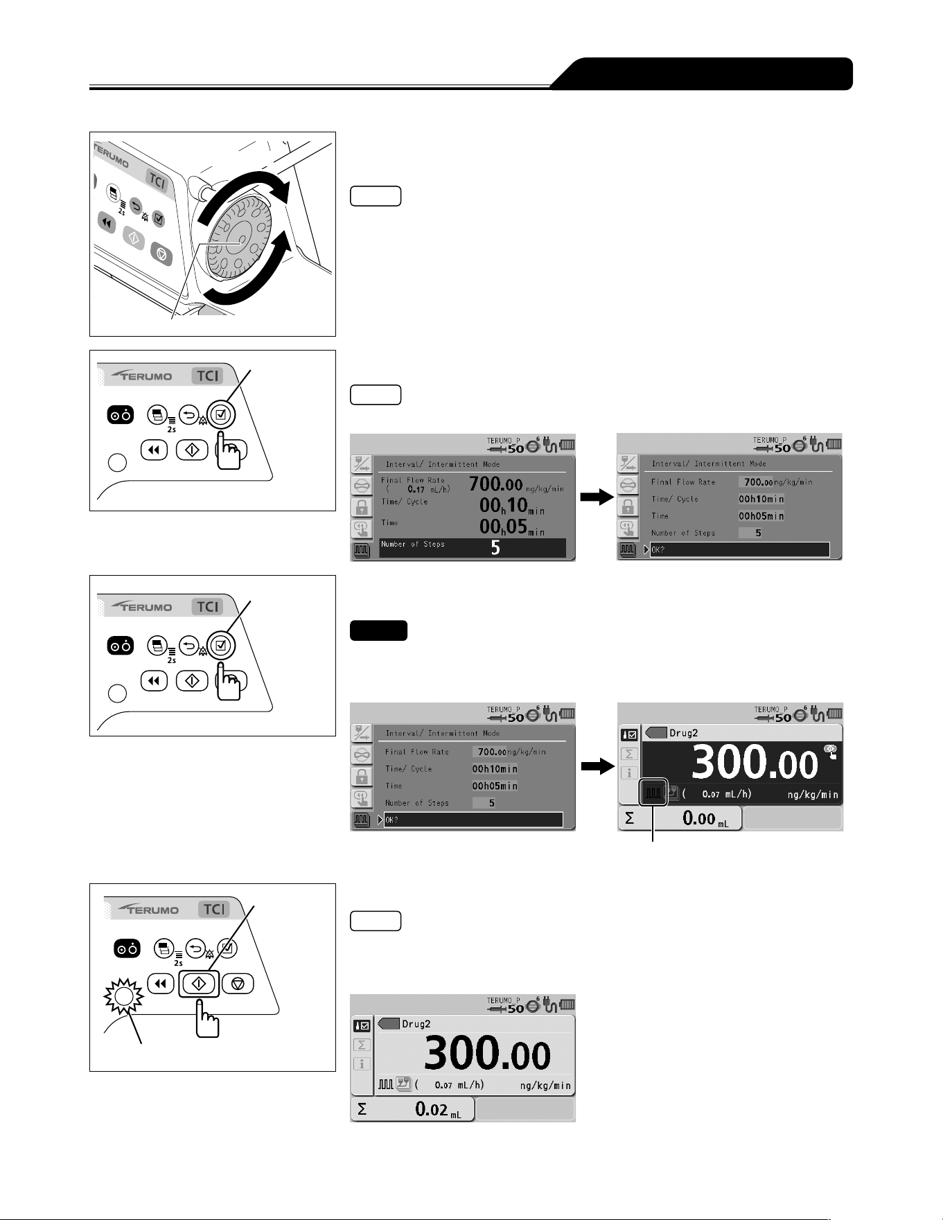
99
Changing Settings on the Menu
Increases value
Dial
Decreases
value
8) Turn the Dial to input the parameters and press the
Confirmation switch.
Notes
With every press of the Confirmation switch, the input area moves to the next one.
When the Back/Mute switch is pressed, the parameter input is cancelled and the
screen returns to the previous status.
Confirmation
switch
9) Input all the parameters and press the Confirmation switch.
Note
The parameter confirmation screen appears.
Confirmation
switch
10) Check the parameter value and that OK? is selected,
press the Confirmation switch.
Checks
The input parameter is correct.
The screen returns to the flow rate screen, and the icon of the selected advanced
dose mode is displayed in the lower left of the flow rate display.
The selected advanced dose mode icon
(See page 96.)
Start switch
Operation indicator (green flashing)
11) Press the Start switch.
Notes
The solution delivery has started and is executed at the specified dose settings.
The operation indicator flashes green.
The volume delivered increases.
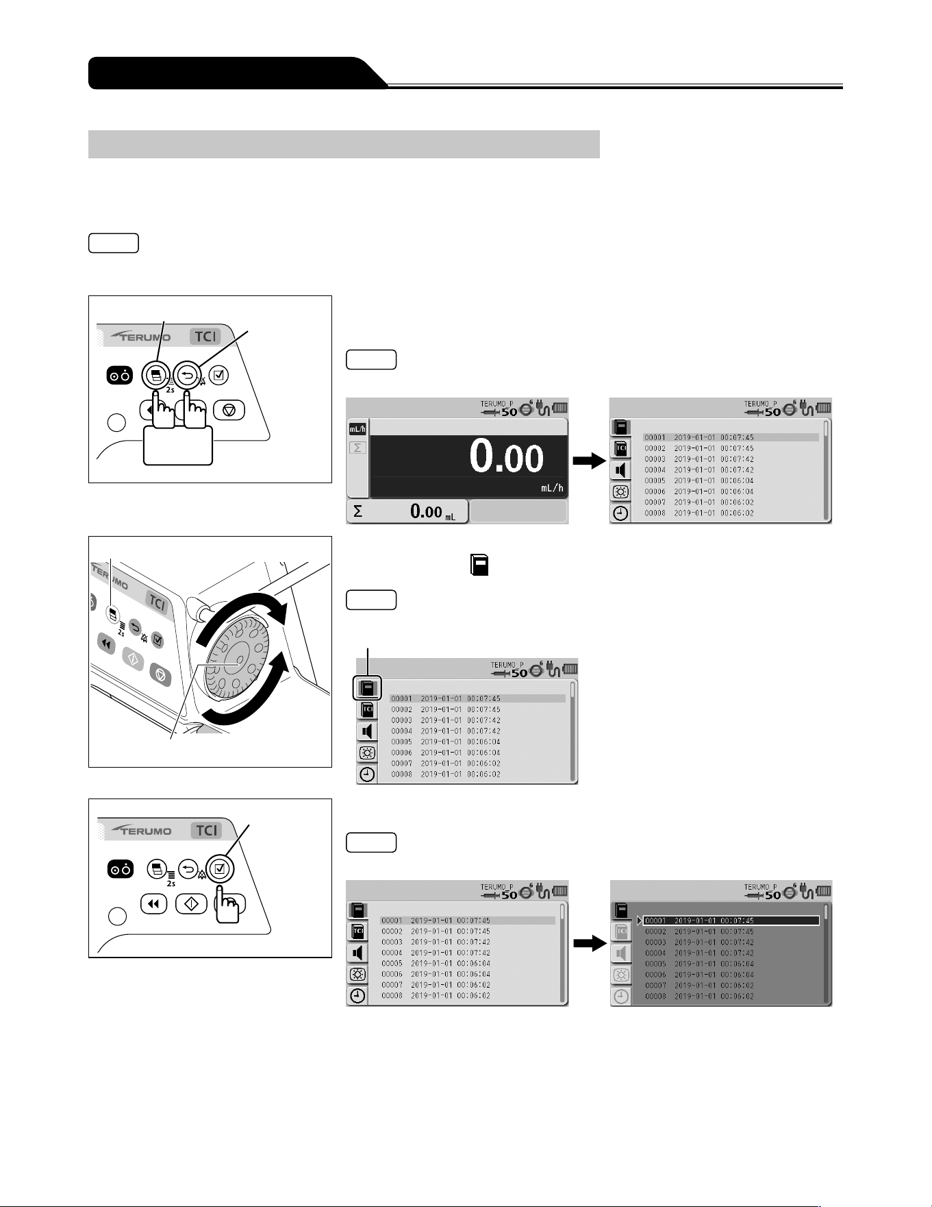
100
Changing Settings on the Menu
History Function
With the history function, operation history (such as date, time, set flow rate, when the solution delivery was started or stopped, or
when an alarm occurred) can be checked. The latest records of max. 10,000 items are stored. If 10,000 items are exceeded, the
records are deleted from the oldest first.
Notes
The battery charge level display indicates the current status regardless of the displayed operation history.
If the pump is dropped then a shock record will be created in the history. This record will be shown at the top of history.
Display select switch
Back/Mute
switch
2 seconds
or more
1) With the Back/Mute switch pressed and held, press and hold
the Display select switch for 2 seconds or more.
Note
The menu 2 screen is displayed and the icons are ready to be selected.
Display select switch
Dial
2) Turn the Dial or press the Display select switch to select the
history tab
.
Note
The history display has appeared.
History tab
Confirmation
switch
3) Press the Confirmation switch.
Note
The existing setting (light blue) changes to the selected status (dark blue).
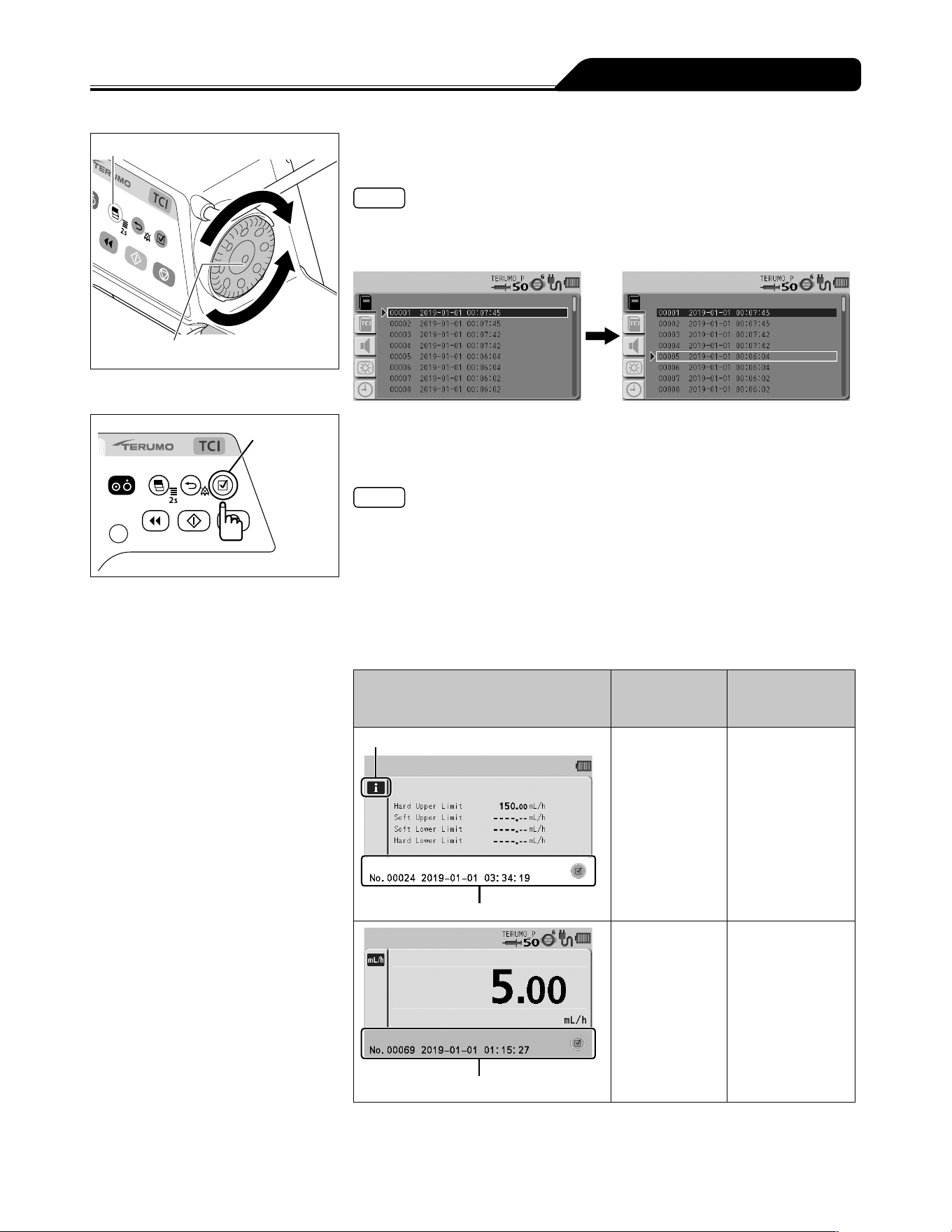
101
Changing Settings on the Menu
Display select switch
Dial
4) Turn the Dial or press the Display select switch to select the
desired operation history.
Notes
Turning the Dial or pressing the Display select switch moves the white frame to the
next operation history item.
Some items of the operation history are divided when a number is assigned.
Confirmation
switch
5) Press the Confirmation switch to display the detailed history
and turn the Dial or press the Display select switch to select
a history.
Notes
The operation histories are classified by operation status and identified with the
colours at the bottom area of LCD as shown in the table below.
Screen transition
- As described in Step 4), the Display select switch or Dial can be used to move up
and down in the list.
- Pressing the Confirmation switch in the list display displays the detailed history.
- Pressing the Back/Mute switch in the detailed history returns to the list display.
- The Display select switch or Dial can be used to move the previous or next
detailed history.
Example of operation history
Colour of
bottom area of
LCD
Operation status
Info. tab
White
White Operation history
information
Green
Green Operation history
during solution
delivery
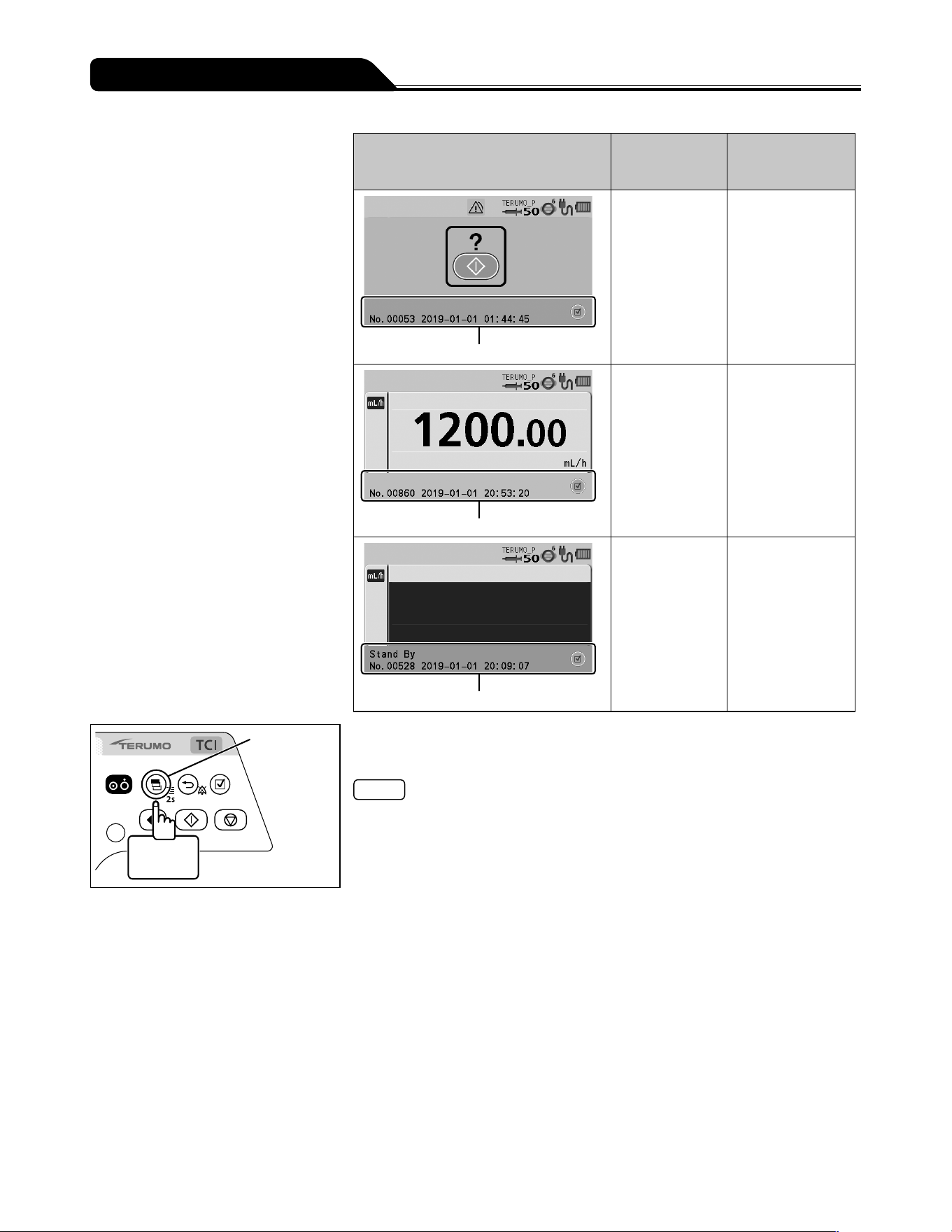
102
Changing Settings on the Menu
Example of operation history
Colour of
bottom area of
LCD
Operation status
Pink
Pink Operation history
during stop
Blue
Blue Operation history
during purge or
bolus (Hands On
Bolus, Hands Free
Bolus)
Orange
Orange Operation history
during standby
Display
select switch
2 seconds
or more
6) Press and hold the Display select switch for 2 seconds or
more to return to the flow rate screen.
Note
Set the correct time and date by following the procedure described on page 110
prior to use.
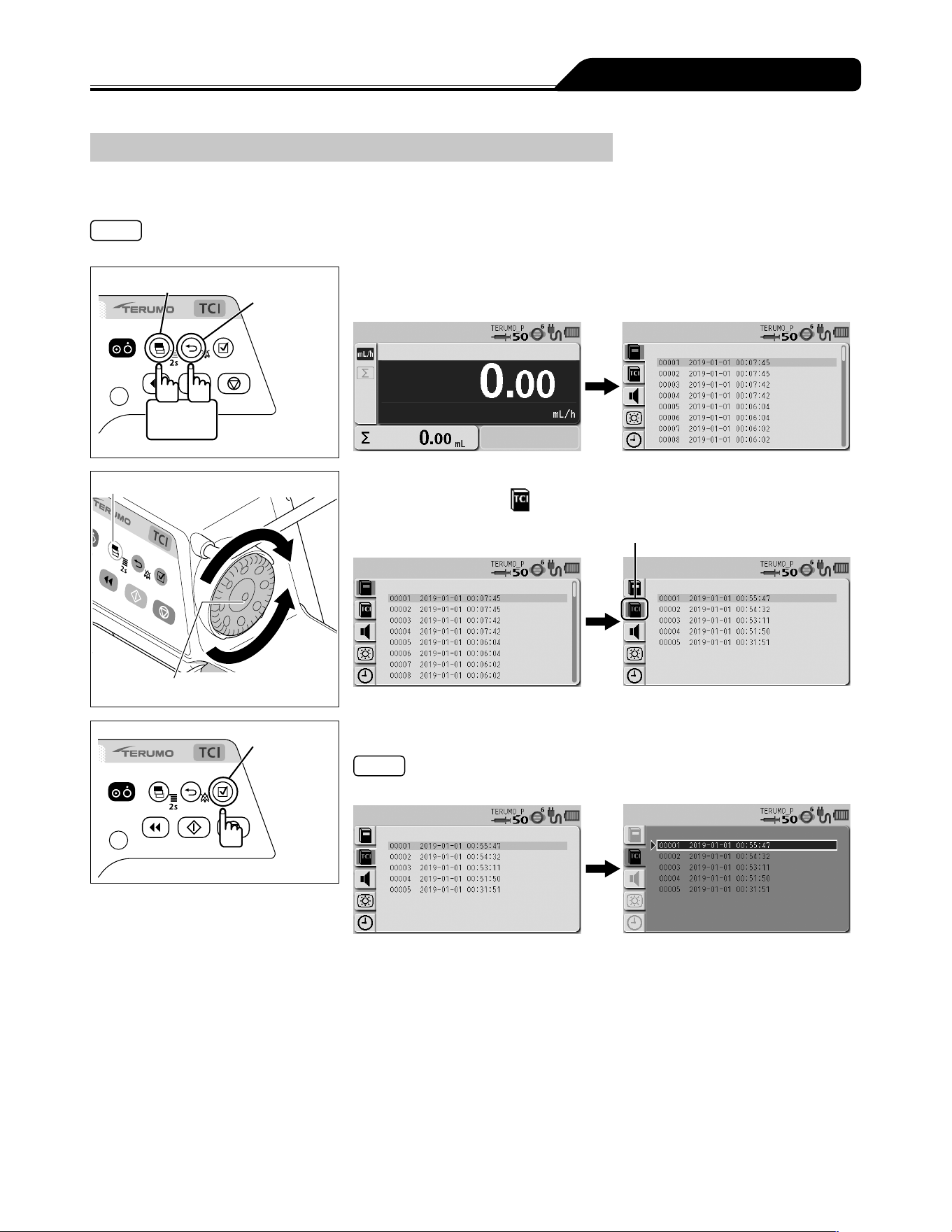
103
Changing Settings on the Menu
TCI operation history function
The TCI operation history provides information such as the starting dates of solution delivery, setting values, and graphs. The
latest records of max. 5 items are stored. If 5 items are exceeded, the records are deleted from the oldest first.
Note
The detailed TCI operation history is not available in the TCI mode.
Display select switch
Back/Mute
switch
2 seconds
or more
1) With the Back/Mute switch pressed and held, press and hold
the Display select switch for 2 seconds or more.
Display select switch
Dial
2) Turn the Dial or press the Display select switch to select the
TCI history tab
.
TCI history tab
Confirmation
switch
3) Press the Confirmation switch.
Note
The existing setting (light blue) changes to the selected status (dark blue).
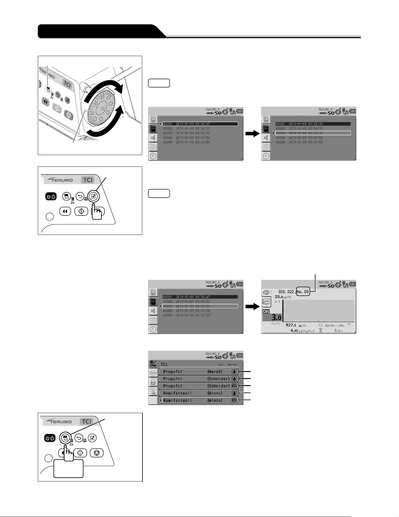
104
Changing Settings on the Menu
Display select switch
Dial
4) Turn the Dial or press the Display select switch to select the
desired operation history.
Note
Turning the Dial or pressing the Display select switch moves the white frame to the
next operation history item.
Confirmation
switch
5) Press the Confirmation switch to display the detailed history
and turn the Dial to select a history.
Notes
Screen transition
- As described in Step 4), the Display select switch or Dial can be used to move up
and down in the list.
- Pressing the Display select switch on the detailed history selects the item in the
graph: Target concentration (Cpt or Cet), X axis, Y axis.
Turning the Dial with the item selected displays as follows:
Target concentration (Cpt or Cet): Indicates changes in a time lapse.
X axis, Y axis: Changes the graph units.
- Pressing the Back/Mute switch in the detailed history returns to the list display.
TCI mode used for the event
No. shows the corresponding number indicating the TCI mode used for the event.
No.01
No.02
No.03
No.04
No.05
Display
select switch
2 seconds
or more
6) Press and hold the Display select switch for 2 seconds or
more to return to the flow rate screen.
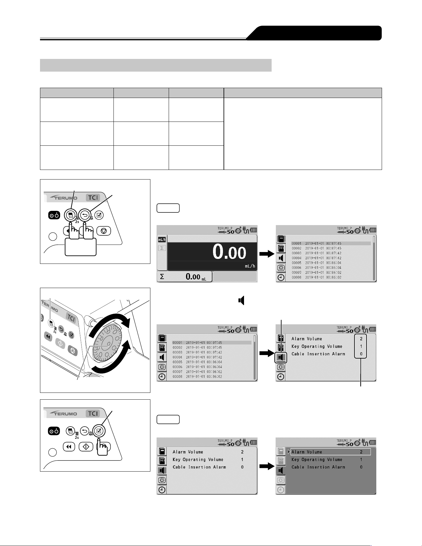
105
Changing Settings on the Menu
Changing the Sound Volume
The Alarm Volume, the Key Operating Volume, and the Cable Insertion Alarm can be set on 4 levels.
Type Volume setting Default setting Note
Alarm Volume 1 to 3, Step 2
0 (very low), 1 (low), 2 (medium), 3 (high),
Step (1 2 3)
The 3 (high) volume is at least 60 dB (A), the 2 (medium)
volume is between (low) and (high), and the 1 (low)
volume is at least 50 dB (A).
The measurements of these volumes were conducted
based on IEC 60601-2-24:2012 (EN 60601-2-24:2015).
For details, refer to IEC 60601-2-24:2012 (EN 60601-2-
24:2015).
Key Operating Volume 0 to 3 1
Cable Insertion Alarm 0 to 3 0
Display select switch
Back/Mute
switch
2 seconds
or more
1) With the Back/Mute switch pressed and held, press and hold
the Display select switch for 2 seconds or more.
Note
The menu 2 screen is displayed and the icons are ready to be selected.
Display select switch
Dial
2) Turn the Dial or press the Display select switch to select the
sound volume tab
.
Current setting value
Sound volume tab
Confirmation
switch
3) Press the Confirmation switch.
Note
The white frame is displayed.
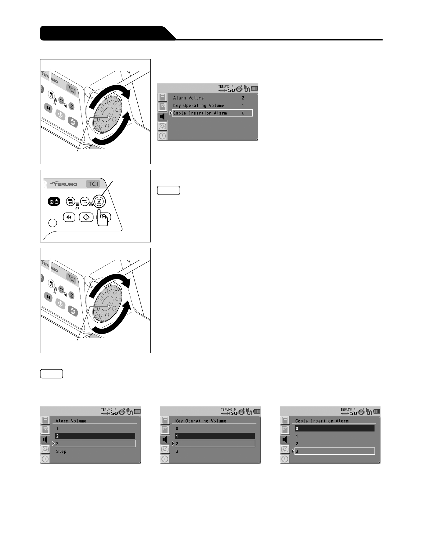
106
Changing Settings on the Menu
Display select switch
Dial
4) Turn the Dial or press the Display select switch to select an
item to change.
Confirmation
switch
5) Press the Confirmation switch to confirm the selection.
Note
The display for the item to be changed has appeared.
Display select switch
Dial
6) Turn the Dial or press the Display select switch to select the
volume.
Notes
Turning the Dial or pressing the Display select switch moves the white frame.
When the white frame is placed on a desired level, the sound is audible.
If Step for the alarm volume is selected, the volume levels increase in three steps.
Alarm Volume Key Operating Volume Cable Insertion Alarm
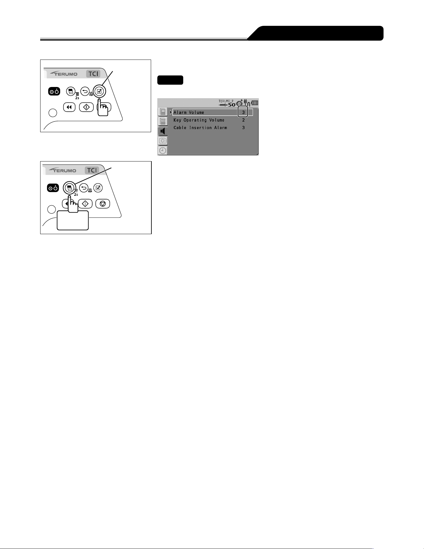
107
Changing Settings on the Menu
Confirmation
switch
7) Press the Confirmation switch to confirm the selection.
Check
The selected volume is displayed.
Display
select switch
2 seconds
or more
8) Press and hold the Display select switch for 2 seconds or
more to return to the flow rate screen.
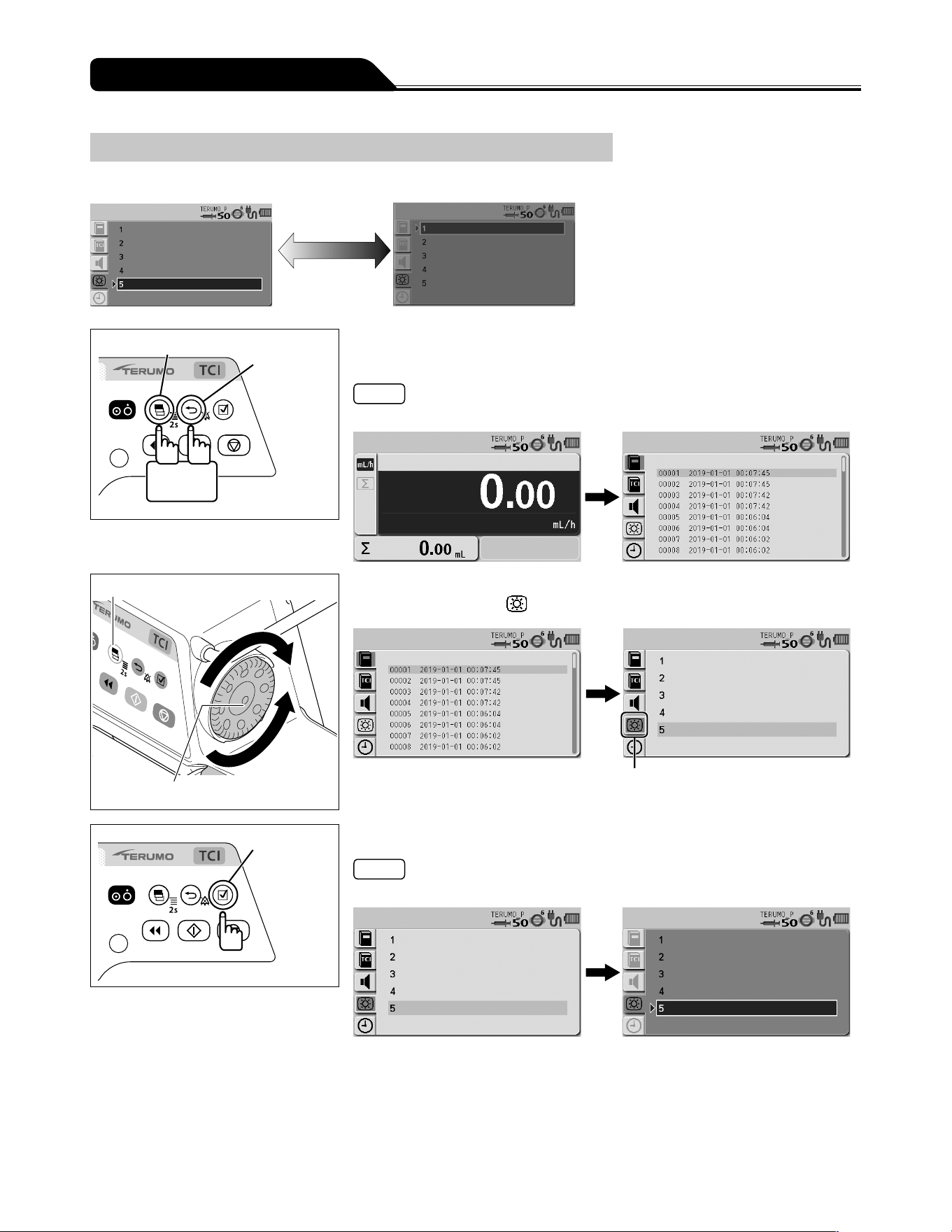
108
Changing Settings on the Menu
Changing the Brightness
The brightness can be set in 5 levels (Default: 5).
Bright Dark
5 4 3 2 1
Display select switch
Back/Mute
switch
2 seconds
or more
1) With the Back/Mute switch pressed and held, press and hold
the Display select switch for 2 seconds or more.
Note
The menu 2 screen is displayed and the icons are ready to be selected.
Display select switch
Dial
2) Turn the Dial or press the Display select switch to select the
brightness tab
.
Brightness tab
Confirmation
switch
3) Press the Confirmation switch.
Note
The existing setting (light blue) changes to the selected status (dark blue).
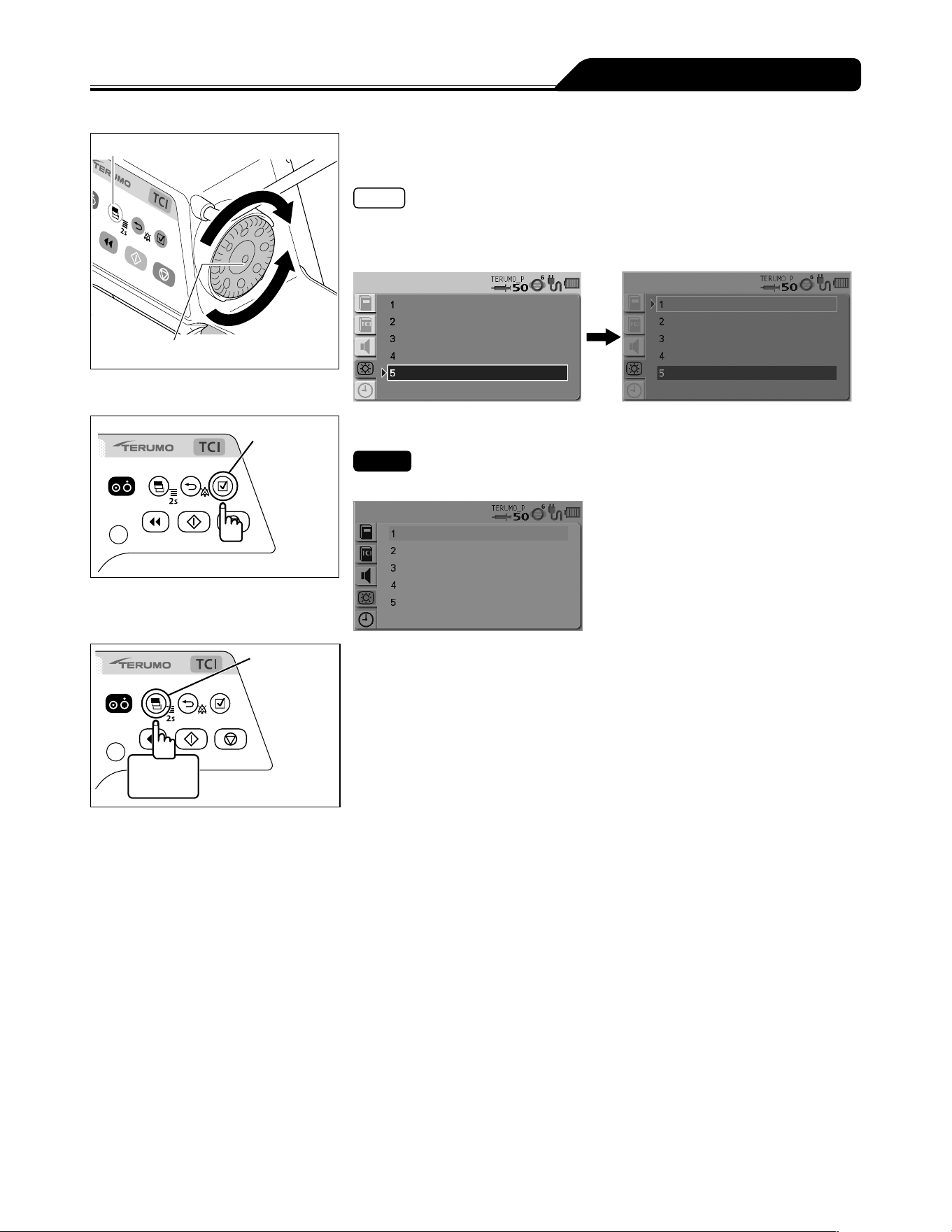
109
Changing Settings on the Menu
Display select switch
Dial
4) Turn the Dial or press the Display select switch to select a
brightness level.
Notes
Turning the Dial or pressing the Display select switch moves the white frame.
When the white frame is placed on a desired brightness level, the brightness level
is shown.
Confirmation
switch
5) Press the Confirmation switch to confirm the selection.
Check
The LCD is displayed with the brightness selected.
Display
select switch
2 seconds
or more
6) Press and hold the Display select switch for 2 seconds or
more to return to the flow rate screen.
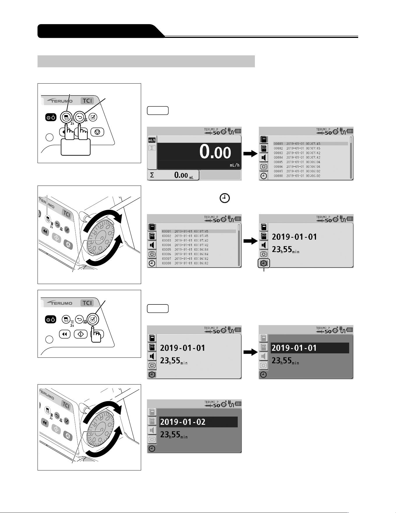
110
Changing Settings on the Menu
Setting the Date and Time
The date and time can be set. Set year, month, date, hour, and minute.
Display select switch
Back/Mute
switch
2 seconds
or more
1) With the Back/Mute switch pressed and held, press and hold
the Display select switch for 2 seconds or more.
Note
The menu 2 screen is displayed and the icons are ready to be selected.
Display select switch
Dial
2) Turn the Dial or press the Display select switch to select the
date and time tab .
Date and time tab
Confirmation
switch
3) Press the Confirmation switch.
Note
Year - month - date is displayed in dark blue (selected).
Increases value
Dial
Decreases
value
4) Turn the Dial to change the date.
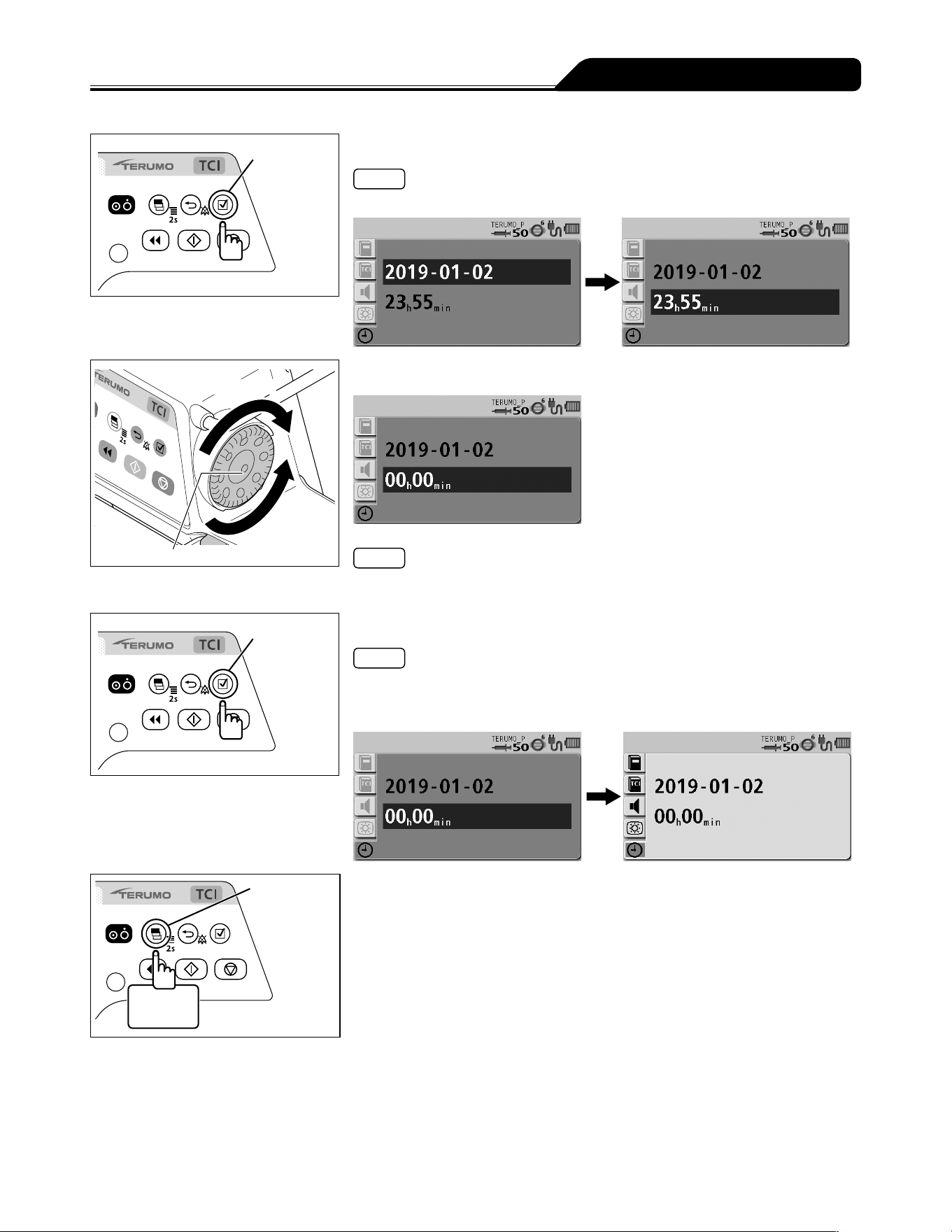
111
Changing Settings on the Menu
Confirmation
switch
5) Press the Confirmation switch.
Note
The date setting is confirmed and hour - minute is displayed in dark blue (selected).
Increases value
Dial
Decreases
value
6) Turn the Dial to change the time.
Note
When the Back/Mute switch is pressed, the parameter input is cancelled and the
screen returns to the previous status.
Confirmation
switch
7) Press the Confirmation switch.
Notes
The time setting is confirmed and the menu 2 screen appears with the icons in the
selected status.
The time is set to 00 seconds.
Display
select switch
2 seconds
or more
8) Press and hold the Display select switch for 2 seconds or
more to return to the flow rate screen.
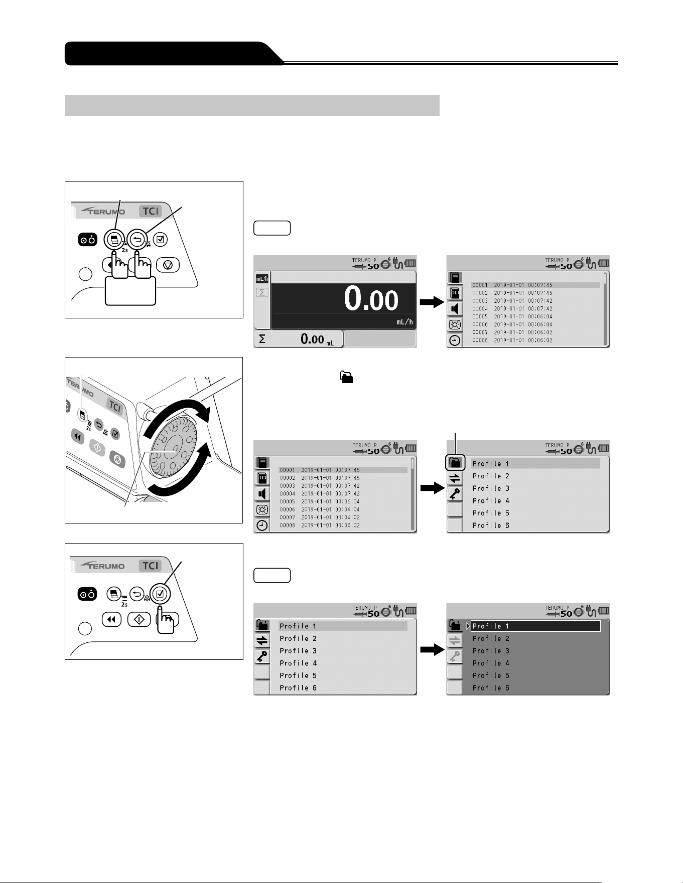
112
Changing Settings on the Menu
Profile
Profiles allow drugs to be classified according to their use and need to be registered in the drug library software. Selecting a profile
can limit the drugs available to each individual profile. Up to 30 profiles can be registered. Profiles can only be selected, if a library
is uploaded to the pump.
See page 66 for how to select the library.
Display select switch
Back/Mute
switch
2 seconds
or more
1) With the Back/Mute switch pressed and held, press and hold
the Display select switch for 2 seconds or more.
Note
The menu 2 screen is displayed and the icons are ready to be selected.
Display select switch
Dial
2) Turn the Dial or press the Display select switch to select the
profile tab
.
If no library or profile is registered, the profile tab is not
displayed.
Profile tab
Confirmation
switch
3) Press the Confirmation switch.
Note
The existing setting (light blue) changes to the selected status (dark blue).
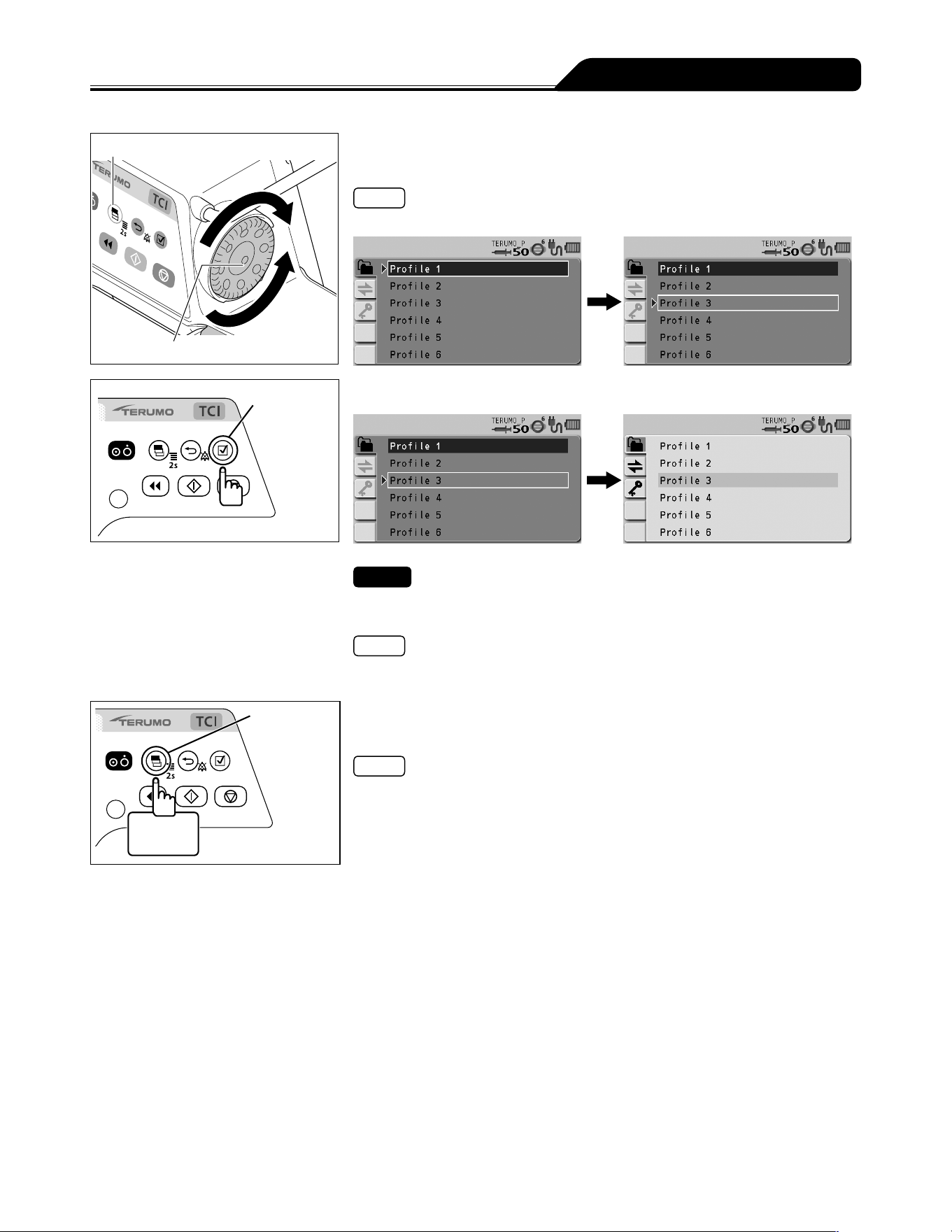
113
Changing Settings on the Menu
Display select switch
Dial
4) Turn the Dial or press the Display select switch to select a
profile.
Note
Turning the Dial or pressing the Display select switch moves the white frame.
Confirmation
switch
5) Press the Confirmation switch to confirm the selection.
Check
In Drug library, only the drugs set in the selected profile are available.
(See page 66).
Note
See the dedicated editing software (TERUFUSION Drug Library Manager or
TERUFUSION Software Package) for profile setting and registration of each drug.
Display
select switch
2 seconds
or more
6) Press and hold the Display select switch for 2 seconds or
more to return to the flow rate screen.
Note
When the AC power has been supplied, the selected profile will be displayed on
the LCD after turning off the power.
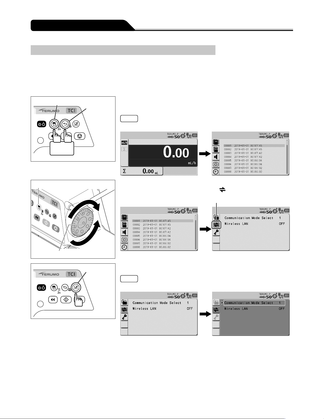
114
Changing Settings on the Menu
Communication Environment
Wireless LAN can be turned ON/OFF and the communication environment can be set. Up to 10 communication environments can
be registered.
Communication environment setting
For details about how to register the communication environment setting to the pump unit, contact TERUMO trained service
technicians.
Display select switch
Back/Mute
switch
2 seconds
or more
1) With the Back/Mute switch pressed and held, press and hold
the Display select switch for 2 seconds or more.
Note
The menu 2 screen is displayed and the icons are ready to be selected.
Display select switch
Dial
2) Turn the Dial or press the Display select switch to select the
communication environment tab
.
Communication environment tab
Confirmation
switch
3) Press the Confirmation switch.
Note
The white frame is displayed.
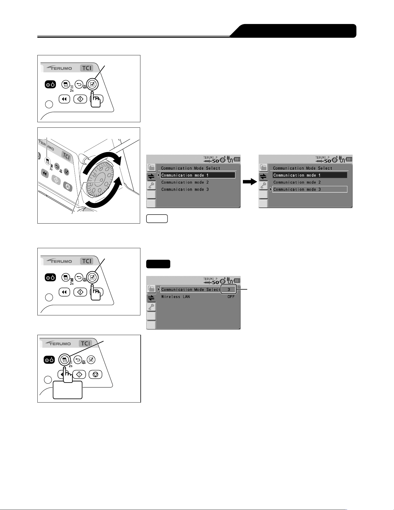
115
Changing Settings on the Menu
Confirmation
switch
4) Check that Communication Mode Select is selected, and
then press the Confirmation switch.
Display select switch
Dial
5) Turn the Dial or press the Display select switch to select the
communication environment you want to set from the list of
registered communication environments.
Notes
Turning the Dial or pressing the Display select switch moves the white frame.
The specified communication environments are restricted depending on the set
profile.
Confirmation
switch
6) Press the Confirmation switch to confirm the selection.
Check
The set communication environment No. is displayed on screen.
Communication
environment No.
Display
select switch
2 seconds
or more
7) Press and hold the Display select switch for 2 seconds or
more to return to the flow rate screen.
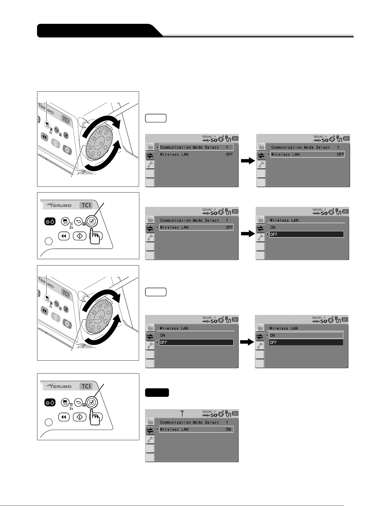
116
Changing Settings on the Menu
Wireless LAN ON/OFF setting
1) Follow Steps 1) to 3) of Communication Environment
(page 114) to display the communication environment
setting screen.
Display select switch
Dial
2) Turn the Dial or press the Display select switch to select
Wireless LAN.
Note
Turning the Dial or pressing the Display select switch moves the white frame.
Confirmation
switch
3) Press the Confirmation switch.
Display select switch
Dial
4) Turn the Dial or press the Display select switch to select ON/
OFF.
Notes
The existing setting has been selected (dark blue).
Turning the Dial or pressing the Display select switch moves the white frame.
Confirmation
switch
5) Press the Confirmation switch to confirm the selection.
Check
The selected wireless LAN setting is displayed.
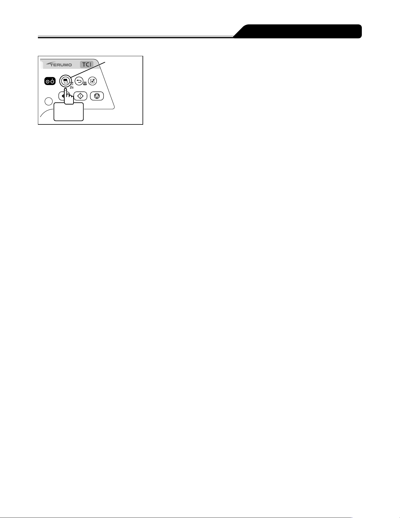
117
Changing Settings on the Menu
Display
select switch
2 seconds
or more
6) Press and hold the Display select switch for 2 seconds or
more to return to the flow rate screen.
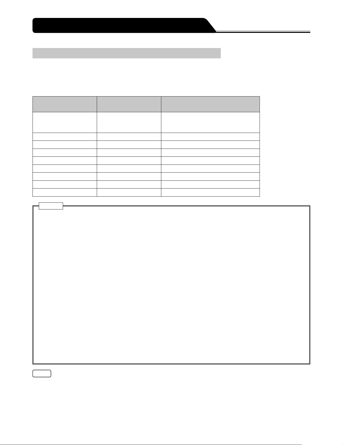
118
Overview
Use infrared communication (IrDA) or wireless LAN to output the status of the pump to a network system (e.g. monitor system or
CIS). (The status of the pump cannot be changed from a network system.)
Ensure that the network system and the pump use the same communication conditions.
List of communication specifications
Communication method
Infrared communication
(IrDA)
Wireless LAN
Transmission rate 115200bps IEEE802.11b: 1Mbps to 11Mbps
IEEE802.11g: 6Mbps to 54Mbps
IEEE802.11n: 6.5Mbps to 72.2Mbps
Data length 8 bits -
Start bit 1 bit -
Stop bit 2 bits -
Parity check None -
Frequency (Europe) - 2412 MHz (ch1) to 2472 MHz (ch13)
Encryption scheme - WPA2 (AES/TKIP), WPA (AES/TKIP), WEP
Operational mode - Infrastructure mode
LAN Standard - IEEE802.11b/g/n
Cautions
When this product is connected with other devices, particularly note the following:
1. When connecting this product with other medical equipment or network system, check its conformance to IEC 60601-
1:2005+A1:2012 (EN 60601-1:2006+A1:2013), IEC 60601-1-2:2007 (EN 60601-1-2:2007) and IEC 60601-1-2:2014 (EN
60601-1-2:2015) prior to use in order to ensure the system safety.
2. When connecting this product with a network system or other equipment, for safety, checking the manufacturers
specifications of the equipment is recommended. In addition, use EMI compliant products for the connection cable.
3. When using the external communication function, pay particular attention, as it is more susceptible to the effect from a
radio knife, mobile phone, radio device, defibrillator, etc. Regularly check that this product is operating normally.
4. When using the wireless LAN communication function, the effect on other equipment by radio interference should be
considered. [It may affect other equipment.]
5. When connecting this product with a network, the settings of this product and the network system need to be
compatible. Contact a vendor specialist for the correct settings and allow only the system administrator to perform
settings. [Failure to connect with correct settings may result in interfering with the original functionality or performance
of this product and affecting the network system.]
Connection to a network including other devices may cause unpredicted and unacceptable risks for the patient, the user,
or a third person. Be sure to identify, analyze, evaluate, and control those risks.
Subsequent changes to the IT-network could introduce new risks and require additional analysis.
- Changes to the IT-network include:
1. Changes in the IT-network configuration.
2. Connection of additional items to the IT-network.
3. Disconnecting items from the IT-network.
4. Update of equipment connected to the IT-network.
5. Upgrade of equipment connected to the IT-network.
Notes
Operating time using the internal battery is decreased when using external communication while using with the internal battery.
The specified message (free message function) can be displayed on the pump unit via communication. (For details, contact
TERUMO trained service technicians.)
About External Communication Functions
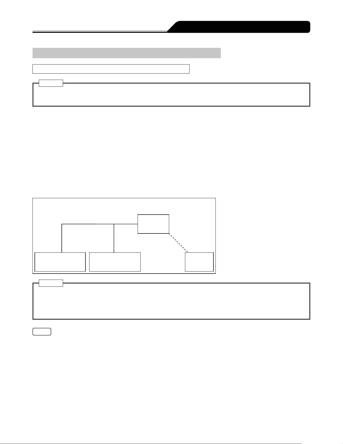
119
About External Communication Functions
Network System Connection
Procedure for Connecting the Network System
Caution
When connecting this product with a network system or other equipment, for safety, checking the manufacturers
specifications of the equipment is recommended. In addition, use EMI compliant products for the connection cable.
< IrDA (For infrared communication)>
Fix the pump into the optional TERUFUSION Communication Rack System and then turn the power on for both so that the pump
and rack system automatically communicate with each other. See the instruction manual for the rack system for communication
between rack system and external device.
<Wireless LAN>
1) Use the TERUFUSION Drug Library Manager or TERUFUSION Software Package to set the
communication environment in the pump.
2) Select a communication environment setting to be used for the pump.
3) Enable the wireless LAN of the pump.
Configuration diagram of wireless LAN
Wired LAN
Network
system
Network system
(TCP Server)
DHCP server
(Installed as needed)
Wireless LAN
Pump
Cautions
When using the wireless LAN communication function, the effect on other equipment by radio interference should be
considered.
When connecting this product with a network, the settings of this product and the network system need to be compatible.
Contact a vendor specialist for the correct settings and allow only the system administrator to perform settings.
Note
TERUMO cannot guarantee the connection.
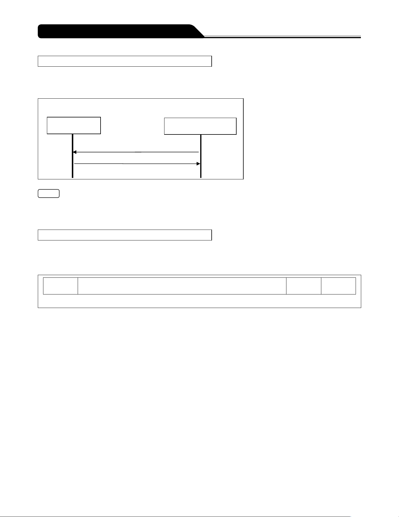
120
About External Communication Functions
Transmission Procedure
When the network system sends an instruction (REQ: REQUEST) to the pump, the pump replies (REP: REPLY) to the instruction.
The pump communicates with the network system on the predefined network (TCP Server) over the wireless LAN.
The following shows an example of the communication sequence.
Communication sequence (polling)
Pump Network system
Request (e.g. the basic operating status)
Reply
Notes
It does not respond to data without a matching device ID (identification information), in other words, received content is not self-
addressed.
Wireless LAN communication is not available when it is attached to the rack system and is conducting IrDA communication.
Packet
<Packet format>
The following shows the packet format.
Packet format
STX
0x02
Packet data (XML format)
(Arbitrary size)
CRC16
(4byte)
ETX
0x03
(Packet data and CRC16 use ASCII code.)
STX
0x02 (Fixed)
Packet data
Data division written in XML format (For details, see this page Packet <Packet data>.)
CRC16
Error detection calculation for the packet data division. The polynomial to be used is CRC-16-CCITT.
ETX
0x03 (Fixed)
Measures for a packet error
If the pump receives data without STX and/or ETX, the data previously received become invalid.
If the pump receives data with the CRC error, the data previously received become invalid.
<Packet data>
For the XML declaration statement, only <?xml version="1.0"?> is allowed.
Do not use the DOCTYPE declaration.
A space, a tab, and any control code including a line break are not allowed.
XML entity reference notation is not supported.

121
About External Communication Functions
Request packet data format
The following shows the request packet data format used when a network system (or TERUFUSION Communication Rack
System) makes a request to the pump.
Request packet data format
<?xml version="1.0"?>
<REQ> <DEVID></DEVID> <CMD></CMD> </REQ>
REQ tag:
This tag and its element are required.
This indicates a request packet from the network system to the pump.
The pump does not reply to a request without this tag.
DEVID tag:
This tag is required.
This tag indicates the device ID of the pump.
The pump replies when the device ID of the element matches that of the pump.
When the network system obtains the device ID of the pump, the element is omitted. If element is omitted, the pump replies to
only the DEVID tag without conditions, and sends its own device ID as the reply data.
CMD tag:
This tag indicates the command and data to the pump.
The pump replies to one CMD tag.
For details on the element commands and data, see page 122.
The element is converted using Base64.
Reply packet data format
The following shows the reply packet data format used when the pump replies to a request packet.
Reply packet data format
<?xml version="1.0"?>
<REP> <DEVID></DEVID> <CMD></CMD> </REP>
REP tag:
This tag indicates the reply from the pump to the request command sent by the network system.
DEVID tag:
This tag indicates the device ID of the pump.
CMD tag:
This tag indicates the command and data from the pump to the request command.
For details on the element commands and data, see page 122 Command Format <Reply>.
The element is converted using Base64.
122
About External Communication Functions
Command Format
<Request>
The following shows the format of a request command received by the pump.
The request command is used as the element of the CMD tag of a request packet format.
Request command format
Sequence Command SubCommand Data
Sequence:
For a command from the network system: 0x00-0x7E
For a command from the TERUFUSION Communication Rack System: 0x80-0xFE
The following sequence numbers are reserved: 0xFF and 0x7F
Command:
For details, see page 123 Data Format.
SubCommand:
For details, see page 123 Data Format.
Data:
Data is sent according to Command or SubCommand.
For details, see page 123 Data Format.
<Reply>
The following shows the format of a reply command the pump sends.
The reply command is used as the element of the CMD tag of the reply packet format.
Reply command format
Sequence Command SubCommand Execution result Data
Sequence:
The pump sends the same value as the sequence number of the request command received.
Command:
The pump sends the same value as that of Command of the request command received.
SubCommand:
The pump sends the same value as that of SubCommand of the request command received.
Execution result:
When the pump has received a request command and successfully processed it, the pump sends 0x00 indicating that
execution is successful.
If the request command failed due to an error, the pump sends a value between 0x11 and 0x15 as the execution result.
The following table lists the execution results.
Item Size Details
Execution result 1 0x00: Successfully processed
0x11: Command or SubCommand cannot be identified or is undefined.
0x12: The command is invalid, being unable to be executed.
0x13: Short message
0x14: Long message
0x15: The parameter is outside the range.
Data:
If the execution is successful (0x00), the pump sends the processing results according to the requested command and the sub
command.
If the execution failed due to errors (0x11, 0x12, 0x14, 0x15), the pump sends the requested command and the sub command.
If the execution failed due to the error (0x13), the pump sends 0x000000.

123
About External Communication Functions
Data Format
<Requesting basic operating status>
Overview
The current basic operating status of the pump is obtained.
Command : 0x01
SubCommand : 0x0000: Basic operating status is Request.
Data
Network system Pump : None
Pump Network system : With data (See below.)
The following table lists the details of the Basic operating status data:
Basic operating status (Do not handle reserved data.)
Item Size (Byte) Details
Software Ver. 2 Range: 0x0000-0xFFFF
Basic operating status 1 Upper 4 bits Lower 4 bits
0x0 Stop (Reserved)
0x1 Start (Reserved)
0x2 Standby (Reserved)
0x3 Purge (Reserved)
0x4 Hands On Bolus (Reserved)
0x5 Hands Free Bolus (Reserved)
0x6-0xF (Reserved) (Reserved)
(Reserved) 1 (Reserved)
(Reserved) 1 (Reserved)
Alarm information 3 b0 (low order) Shutdown Notice alarm
b1 Link Interruption alarm
b2 Completion alarm
b3 Occlusion alarm
b4 Syringe Displacement alarm
b5 Plunger Displacement alarm
b6 Slider Displacement alarm
b7 Syringe Barrel Detection alarm
b8 Nearly Empty alarm
b9-b12 (Reserved)
b13 Power Failure alarm
b14 (Reserved)
b15 AC power detector function
b16 No Flow Rate alarm
b17 Flow Rate/VTBI Volume Judgment alarm
b18 No VTBI alarm
b19 Battery alarm
b20 Start Reminder
b21 Pressure alarm
b22 Maintenance timer
b23 (high order) Battery Replacement Time/Failure alarm
One bit used for each item. (1 indicates active.)

124
About External Communication Functions
Item Size (Byte) Details
Power status 1 b0-b3 (low order) Battery level
0x0: (Reserved)
0x1: Remaining battery level, 1 bar
0x2: Remaining battery level, 2 bars
0x3: Remaining battery level, 3 bars
0x4: Remaining battery level, 4 bars
0x5: Remaining battery level, 5 bars
0x6-0xF: (Reserved)
b4-b5 Power type
0x0: Battery drive
0x1: AC drive
0x2-0x3: (Reserved)
b6-b7 (high order) Sub-battery status
0x0: (Reserved)
0x1: Sub-battery, normal
0x2: Sub-battery, abnormal
0x3: (Reserved)
Operation monitor 1 b0-b1 (low order) Occlusion monitor (0x0: 0%, 0x1: 25%, 0x2: 50%,
0x3: 75%)
b2 (Reserved)
b3 Alarm sound status (0: Without sound, 1: With
sound)
b4 Keypad lock status (0: Not locked, 1: Locked)
b5 Plunger status monitor (0: Set, 1: Not set)
b6 (Reserved)
b7 (high order) (Reserved)
One bit used for b2-b7. (1 indicates active.)
Syringe status 1 0x0 None
0x1 (Reserved)
0x2 5 mL
0x3 10 mL
0x4 20 mL
0x5 30 mL
0x6 50/60 mL
0x7-0xFF (Reserved)
Flow rate 3 Value of 100 times the set flow rate
Volume delivered 3 Value of 100 times the volume delivered
VTBI 3 Value of 10 times the VTBI
Infinite: 0xFFFFFF
Invalid value (when the function is disabled): 0xEEEEEE
Dosage rate 3 Value of 100 times the dosage
Unit of dosage rate 1 0x00: mL/h
0x04: μg/kg/min
0x08: mg/kg/h
Weight 2 Value of 10 times the weight
Invalid value (when the function is disabled): 0xFFFF
Dilution 3 Value of 100 times the dilution
Invalid value (when the function is disabled): 0x000000

125
About External Communication Functions
Item Size (Byte) Details
Unit of dilution 1 0x12: μg/mL
0x13: mg/mL
Invalid value (when the function is disabled): 0x00
Drug library Ver. 2 Version of the drug library
Drug library is registered: 0x0001-0xFFFF
Drug library is not registered: 0x0000
Drug library number 2 Number of the drug library
Selecting dose mode (weight mode) No.1 (μg/kg/min): 0x0FFD
Selecting dose mode (weight mode) No.2 (mg/kg/h): 0x0FFE
Selecting dose mode (weight mode) No.3 (mg/kg/h+DIPRIVAN): 0x0FFC
Invalid value (when the function is disabled): 0x0000
Occlusion pressure
setting
1 bit0-bit3: Setting of occlusion pressure. 1 to 10.
Occlusion pressure range: 0x01-0x0A
bit7: Setting of occlusion detection pressure 1 = In 10 levels
(bit4-bit6: Reserved)
Hands On Bolus flow
rate
2
100.00 to 1200.00 mL/h (100 mL/h step)
Hands Free Bolus VTBI
3
Value of 100 times the Bolus VTBI
Invalid value (when the function is disabled): 0x000000
Hands Free Bolus dose
time (Bolus VTBI time)
2
0 to 3600 s (1 s step)
Invalid value (when the function is disabled): 0x0000
Hands Free Bolus flow
rate
3
Value of 100 times the flow rate
Invalid value (when the function is disabled): 0x000000
Syringe brand number 1 Brand number of the syringe selected
OTCI library version 2 b0-b14 (lower) Version number
Range: 0x01-0x7FFF
OTCI library unregistered: 0x0000
b15 (upper) (Reserved)
OTCI library number 1 Range: 0x01-0x05
When the dose mode other than TCI is selected: 0x00
(Reserved) 1 (Reserved)
Prediction method 1 0x00: Plasma TCI, 0x01: Effect-site TCI
When the dose mode other than TCI is selected: 0x00
Age 1 12 to 100: 1 year step
Range: 0x0C-0x64
No age setting (the setting is cleared): 0xFF
Gender 1 0x00: Male, 0x01: Female
No gender setting (the setting cleared): 0xFF
Height 1 100-250 cm, 1 cm increments
Range: 0x00-0xFA
No height setting (the setting cleared): 0xFF
(Reserved) 1 (Reserved)
Target concentration 2 Value of 100 times the concentration 0.00 to 50.00 (0.10 step)
Range: 0x0000-0x1388
When the dose mode other than TCI is selected: 0x0000
Target concentration
unit
1 0x11: ng/mL, 0x12: μg/mL
When the dose mode other than TCI is selected: 0x00
Decrement
concentration
2 Value of 100 times the concentration 0.01 to 50.00 (0.10 step)
Range: 0x0001-0x1388
When the dose mode other than TCI is selected: 0x0000

126
About External Communication Functions
Item Size (Byte) Details
Plasma limit 1 200-350%, subtract 100 from the value (1% step)
Range: 0x64-0xFA
The upper limit undefined: 0x00
When the dose mode other than TCI is selected: 0x00
Maximum flow rate 3 Value of 100 times the maximum flow rate
0.00 to 999.00 (0.01 step)
Range: 0x000000-0x01863C
When the maximum flow rate is not set or when the dose mode other than
TCI is selected: 0x000000
Predicted plasma
concentration
3 Value of 100 times the concentration 0.00 to 50.00 (0.10 step)
Range: 0x000000-0x001388
When the dose mode other than TCI is selected: 0x000000
Predicted effect-site
concentration
2 Value of 100 times the concentration 0.00 to 50.00 (0.10 step)
Range: 0x0000-0x1388
When the dose mode other than TCI is selected: 0x0000
Predicted awakening
time
3 Hour:minute:second 00:00:00 to 99:59:59
Range: 0x000000-0x995959
When the initial flow rate is not set or when the dose mode other than TCI is
selected: 0x000000
Elapsed time 3 Hour:minute:second 00:00:00 to 99:59:59
Range: 0x000000-0x995959
Before the first solution delivery is started in the TCI mode or when the dose
mode other than TCI is selected: 0x000000
(Reserved) 2 (Reserved)
(Reserved) 2 (Reserved)
Volume delivered by
TCI
2 Mass values (mg or μg) of volume delivered: 0 to 65535 (1 step)
Range: 0x0000-0xFFFF
When the dose mode other than TCI is selected: 0x0000
Volume unit delivered
by TCI
1 0x12: μg, 0x13: mg
When the dose mode other than TCI is selected: 0x00
Total number of bytes 82
* For more details, contact TERUMO trained service technicians.

127
About External Communication Functions
Format of Transmitted and Received Packet
When a network system communicates with the pump, the monitor obtains the device ID from the pump identifying itself. Then, the
monitor starts to communicate with the pump.
The following shows the format of communication packet.
1. Device ID request (network system
pump)
Data example
[STX]<?xml version="1.0"?><REQ><DEVID></DEVID></REQ>8411[ETX]
Note) [STX]: 0x02, [ETX]: 0x03
* In this case, CRC is 8411.
2. Device ID reply (pump
network system)
Data example
[STX]<?xml version="1.0"?><REP><DEVID>000100700000001201000001</DEVID></REP>D38C[ETX]
Note) [STX]: 0x02, [ETX]: 0x03
* This is an example of the reply where the device ID is 000100700000001201000001.
In this case, CRC is D38C.
3. Basic operating status request (network system
pump)
Data example
[STX]<?xml version="1.0"?><REQ><DEVID>000100700000001201000001</DEVID><CMD>AQEAAA==</CMD></REQ>
A9A4[ETX]
Note) [STX]: 0x02, [ETX]: 0x03
* This is an example of the basic operating status request where the device ID is 000100700000001201000001, the sequence
number is 01, the command is 01, and the sub command is 0000.
In this case, CRC is A9A4.
4. Basic operating status reply (pump
network system)
Data example
[STX]<?xml version="1.0"?><REP><DEVID>000100700000001201000001</DEVID><CMD>AAEAAAAEAwAQAAAAAFUAB
gAAAAAAAO7u7gAAAAgCvAAD6BOZmQAAhgAAAAAAAAAAAAALAAIBAgAo////AZASAHj6AEL3AAAAAAAAAAAAAAA
ARQApAAAT</CMD></REP>901D[ETX]
Note) [STX]: 0x02, [ETX]: 0x03
* This is an example of the reply where the pump is stopped.
In this case, CRC is 901D.

128
In order to ensure the safe use of the syringe pump, make sure it is cleaned and inspected after use and stored in an appropriate
environment. If you find any damage or malfunction, immediately stop using the pump and contact TERUMO trained service
technicians.
Cleaning
Cautions
Clean the AC inlet, slider and clutch on a regular basis. Failure to conduct the regular cleaning may result in damage,
failure or malfunction to/of this product.
If any parts (clamp, clutch part etc.) of this product need to be removed for cleaning, contact TERUMO trained service
technicians.
When disinfecting, do not use a sterilizer. Use a gauze (damp with antiseptic solution) to wipe the product, and wipe off the
antiseptic solution with a gauze (damp with cold/lukewarm water), and then thoroughly wipe off any moisture with a dry soft
cloth.
Before cleaning, always turn off the power and disconnect the AC power cable. Otherwise it may cause an electrical shock
hazard. When AC power is supplied by the optional rack system (Model: TE-RS700, TE-RS800, TE-RS811), first remove
the pump from the rack system, then conduct cleaning.
If any adhered drug solution is present, the solution delivery or alarm detection may not operate correctly or may interfere
with the normal operation of the clamp part and/or movable part of the pole clamp. If any drug solution is present, clean
immediately with a cotton swab.
Do not wipe with undesignated alcohol, other organic solvents such as thinner, or povidone-iodine. Using organic solvent
or any antiseptic solution other than those permitted for use may result in damage to or failure of this product.
Do not use an electric dryer to dry this product. This product may be damaged.
This product and the pole clamp does not have a waterproof structure. Therefore, do not wash with running water or
immerse in water. It may cause damage or failure of the product.
If the flange holder or clutch suffers from stiff movement or gets very dirty, it should be cleaned with a damp (not wet) soft
cloth.
Examples of disinfectants (ingredient names) which can be used are listed below.
Examples of Cleaning Disinfectants (Ingredient Names)
Ingredient Name Dilution (e.g.)
Chlorhexidine gluconate 5%
Benzalkonium chloride 10%
Ethanol* 76.9 - 81.4vol%
When using disinfectant, follow the instruction manual of each disinfectant (regarding degree of dilution, etc.).
* Do not use ethanol to disinfect the following:
One Touch Pole Clamp (specified parts only)
For details, see page 129.
After Use
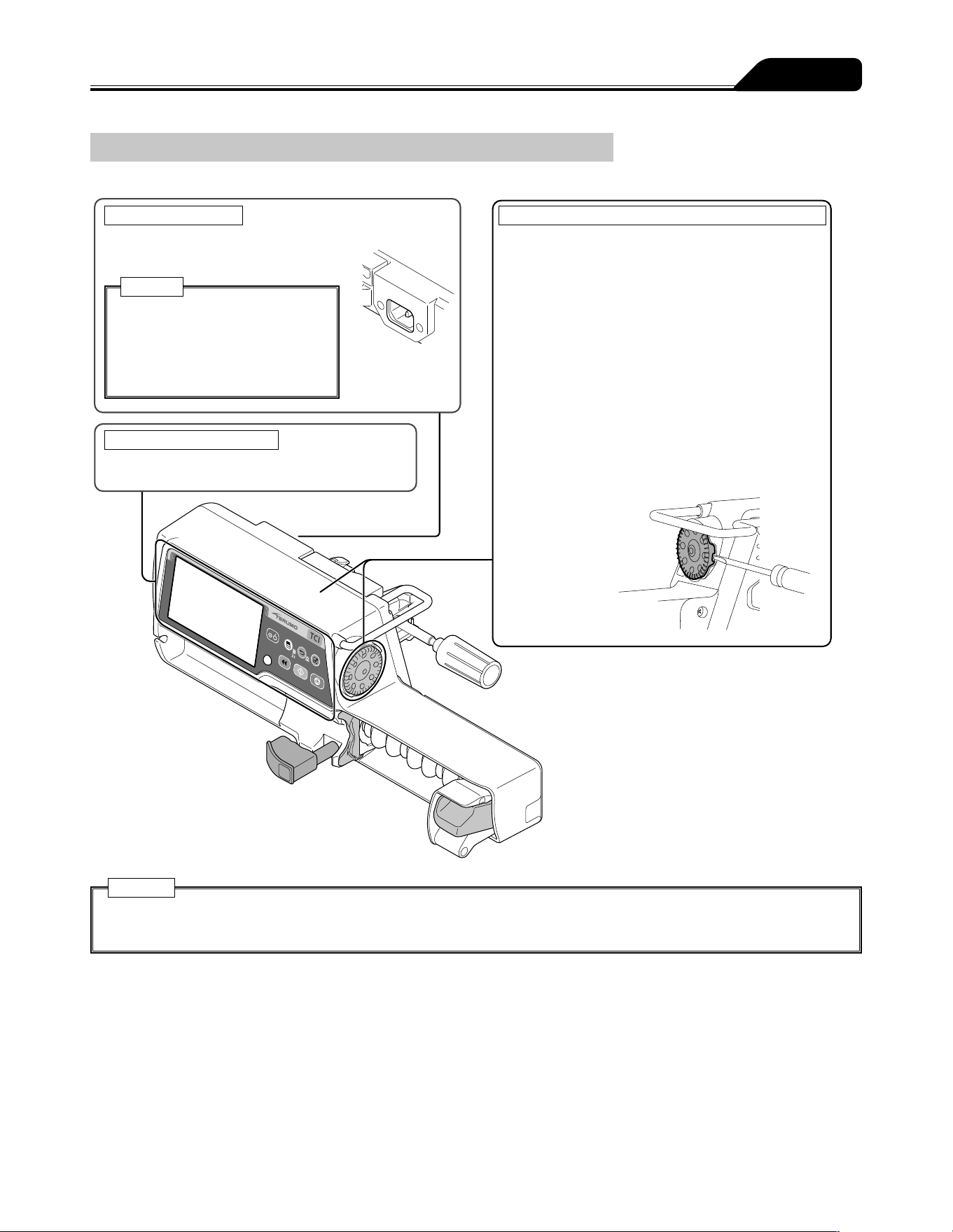
129
After Use
How to Clean Components
After use, clean all components as described below.
Caution
After cleaning, completely dry the
AC inlet before use. Otherwise an
electric shock or short circuit may
occur resulting in failure of the
product.
Cleaning the AC inlet
Lightly wipe off dirt with a cotton swab
or damp cloth (not wet).
Cleaning the panel surface
Wipe with a damp (not wet) soft cloth.
Cleaning the outside of the syringe pump and the Dial
Wipe with a damp (not wet) soft cloth.
When disinfecting, use a designated disinfectant.
The Dial is fixed to the body of the pump with a
magnet. Remove it following the procedure below
before cleaning.
How to remove the Dial
1 Turn the groove of the Dial to the rear of the device.
2 Place a flathead screwdriver in the groove of the
Dial and push it outwards.
3 Remove the Dial and wipe clean the body and the
Dial.
Grease is applied to the shaft. Do not wipe it off.
4 When you have finished cleaning, fit the Dial back
onto the body.
5 After fitting, turn on the power.
Check that setting for flow rate etc., can be
performed.
Cautions
Do not rub the panel surface with a hard object.
Do not rub with a hard object such as forceps or with a sharp object etc.
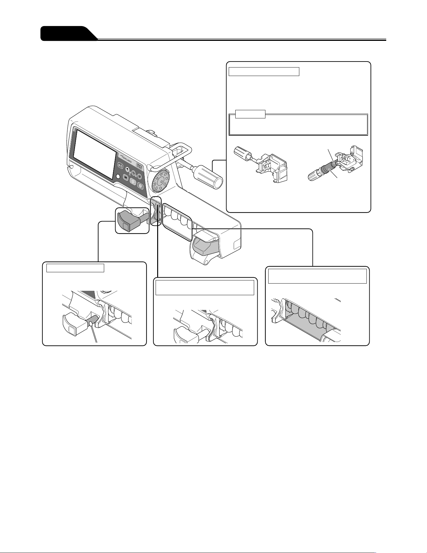
130
After Use
Cleaning the pole clamp
Detach the pole clamp from the pump, and wipe with
a damp (not wet) soft cloth.
* Do not use ethanol to disinfect the rubber cover
and the sliding sites as indicated by
■
.
Caution
Do not soak the pole clamp in water to clean it.
Pole clamp
(screw type)
TERUFUSION
One Touch Pole Clamp
(Optional accessory)
Cleaning the clamp
Wipe with a cotton swab or
damp cloth (not wet).
Cleaning the flange slit and the
Holding flange.
Wipe with a damp (not wet) soft cloth.
Cleaning the rubber protector and
around the rubber protector
Wipe with a damp (not wet) soft cloth.
Rubber cover
Sliding sites

131
After Use
Storage
After inspecting the pump, store it in an environment which conforms to the following storage conditions.
Temperature: -20°C to 45°C
Humidity: 10% to 95%RH (non-condensing)
Atmospheric pressure: 50 to 106kPa (500 to 1060hPa)
Ensure that the battery is charged in preparation for its next use.
Warnings
Since this product does not have an airtight structure, it should not be used or stored in an active gas environment
(including sterilizer gas), nebulizer-sprayed environment, high-humidity environment, etc. It should not be submerged
into water. If the electronic components inside the product are affected, there may be subsequent damage and time
degradation which will cause failure of this product.
The product should not be used or stored in a flammable environment.
Cautions
Do not store this product in a place with a high level of vibration, dust, mist or corrosive gas.
Do not expose this product to direct sunlight or ultraviolet irradiation for a long period of time. The exterior may experience
colour change, deformation or deterioration.
Do not store this product in a place where an environment of atmospheric pressure, temperature, humidity, ventilation, salt
content or sulfur content may cause an adverse effect.
Do not store this product in a storage area for chemicals or in a place that generates gases.
When transporting this product, avoid any shock, vibration, dust, high temperature and high humidity. Transport conditions:
Temperature: -20 to 60°C, Humidity: 10 to 95%RH (non-condensing), Atmospheric pressure: 50 to 106kPa (500 to
1060hPa)
If the battery is not used for a long period after being charged, the amount of charge decreases due to self-discharge. Do
not store the battery in a discharge status. Storing the battery left in a discharge status may cause degradation, resulting in
making it unavailable in emergency situations.
132
Maintenance and Inspection Items by TERUMO Certified Service Technicians
Cautions
If any fault is observed, immediately stop using the product and contact TERUMO trained service technicians.
Do not disassemble, make alterations (including actions that interfere with the functionality or performance such as taping
the LCD or a movable part) to, or repair this product. This may result in failure, damage or device performance degradation
of this product.
Do not use any replacement parts other than those specified. The original functionality or performance of this product may
not be achieved.
Periodic Maintenance
Perform a periodic maintenance inspection to ensure safe operation and the longest possible life of the syringe pump. Contact your
local distributor for details on the nature and frequency of the maintenance inspection.
From TERUMO
When ordering repairs or maintenance inspections, if there is a possibility of infection, disinfect the product in advance.
Battery replacement
Periodically replaced parts
Over a period of time, the battery will gradually deteriorate. Please see chart below for replacement schedule.
Part name Elapsed years Replacement reason
Battery (Lithium-ion battery) 2.5 to 3 years Even when charged, after a short period of time Battery alarm
is displayed and the buzzer sounds.
Sub-battery (Nickel-metal-hydride battery) 1 to 2 years The Power Failure alarm does not function properly.
* Depending on frequency of use and usage environment, the time for replacement for each part may change and replacement of
parts other than those scheduled for replacement may also be required. Consult TERUMO trained service technicians regarding
necessity and replacement.
* The life span of the equipment is at least 6 years in the case of standard use.
Fuse replacement
This product incorporates a fuse inside the structure. For replacement, contact TERUMO trained service technicians.
Waste and Recycle
Electrical and electronic equipment (EEE) and batteries contain materials, components and substances which can be dangerous to
the environment and harmful to human health if waste electrical and electronic equipment (WEEE) and batteries are not disposed
of correctly.
Waste electrical and electronic equipment and batteries must not be disposed of with the remainder of unseparated waste, but
should instead be collected separately. In this way, the environmental impact associated with disposal of WEEE and batteries is
reduced and there will be more opportunity for reusing, recycling and recovering WEEE and recycling batteries.
The Lithium-ion battery and Nickel-metal-hydride battery should be removed from the equipment by TERUMO certified service
technicians. Please contact your local distributor.
At end of life, please dispose of this equipment and batteries according to your local regulations. Contact your local distributor or
municipality for details of the available collection schemes. The embedded memory back-up lithium coin battery, collected together
with this equipment at end of life as WEEE, is to be removed and treated by the recycling center.
Maintenance and Inspections
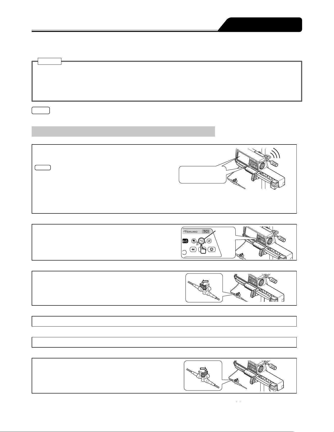
133
When an alarm/error occurs, the factors below may be the cause. Follow the procedure for dealing with each alarm/error as it
arises.
Cautions
If the fault persists even after the following measures, a device failure is suspected. Contact TERUMO trained service
technicians to request repair.
Even under the same condition, the alarm timing depends on the alarm sensitivity level.
Before pressing the Start switch to resume solution delivery after cancelling an alarm condition, ensure that you check the
flow rate and VTBI settings.
Note
If there is an alarm condition as the power is turned on, the alarm display flashes but the buzzer does not sound.
Troubleshooting procedure
OFF
OFF
Alarm!
(Pump stops)
LCD and operation
indicator flashes red
Alarm
Back/Mute
switch
Open
Close
1) Alarm (e.g. High priority alarm).
Alarm displayed on LCD. Operation indicator flashes red.
Check the status such as stopped solution delivery.
Notes
The priority of the alarm status is as follows:
(1) High priority: Alarms flashing red on LCD
(2) Medium priority: Alarms flashing yellow on LCD
(3) Low priority: Alarms lighting up yellow on LCD.
* Refer to the Alarm icon on page 13 for the alarm priority.
When more than one alarm sounds at the same time, the higher priority alarm is displayed on the LCD. Be sure to stop all
the activated alarms by the relevant countermeasures.
2) Mute and check alarm content.
When the alarm is muted with the Back/Mute switch, the
alarm content will be displayed. Press the Back/Mute switch
again to return to the flow rate screen. (The type of alarm
flashes in the lower part of the screen.)
3) Close the three way stopcock etc.
(if in use)
4) Inspect the cause.
Check any applicable occurrence/cause from pages 135 to 145.
5) Eliminate the cause.
Eliminate the cause in accordance with the instructions from pages 135 to 145.
6) Open the three way stopcock etc.
(if in use)
Troubleshooting

134
Troubleshooting
Start switch
7) Confirm and restart.
Check the flow rate, VTBI, etc.,
and resume the solution delivery.
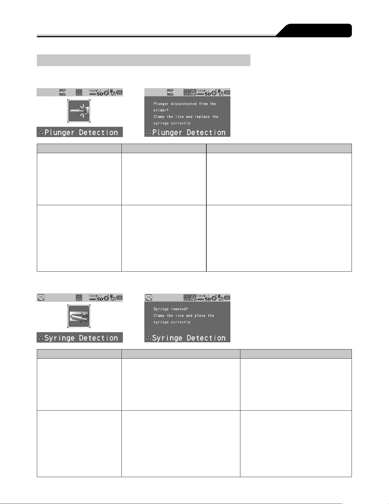
135
Troubleshooting
High priority alarm
Plunger Displacement alarm
Occurrence Cause Action
LCD: The Plunger
Displacement alarm display
flashes red.
Operation indicator: Flashes
red.
Buzzer: Activates.
Pump: Stops.
The plunger has been
displaced during solution
delivery.
1. Re-set the syringe correctly.
(See pages 32 and 51.)
2. Prime the line, ensuring that the plunger is kept in the
slider to prevent the solution from being delivered to
the patient. (See pages 38 and 58.)
LCD: The Plunger
Displacement alarm display
flashes red.
Operation indicator: Flashes
red.
Buzzer: Activates.
Pump: Remains stopped.
Unable to start even after the
syringe has been correctly set.
Drug solution is adhered on
the plunger detector.
The malfunction of the internal
sensor of the plunger detector
is suspected.
(After the alarm is issued, the
solution delivery cannot start
while the power is on.)
If any adhered drug solution is present, turn off the
power and clean the plunger detector.
If the problem persists, contact TERUMO trained
service technicians to request repair.
Syringe Displacement alarm
Occurrence Cause Action
LCD: The Syringe
Displacement alarm display
flashes red.
Operation indicator: Flashes
red.
Buzzer: Activates.
Pump: Stops.
The syringe has been displaced during
solution delivery.
1. Replace the syringe correctly.
(See pages 32 and 51.)
2. Prime the line, ensuring that the
plunger is kept in the slider to prevent
the solution from being delivered to the
patient. (See pages 38 and 58.)
LCD: The Syringe
Displacement alarm display
flashes red.
Operation indicator: Flashes
red.
Buzzer: Activates.
Pump: Remains stopped.
Unable to start even after the
syringe has been correctly set.
Drug solution is adhered on the syringe
clamp and/or flange holder, or they are
damaged.
The malfunction of the internal sensor of
the syringe clamp and/or flange holder is
suspected.
(After the alarm is issued, the solution
delivery cannot start while the power is on.)
If any adhered drug solution is present,
turn off the power and clean the syringe
clamp and/or flange holder.
(See page 129.)
If the problem persists, contact TERUMO
trained service technicians to request
repair.

136
Troubleshooting
Slider Displacement alarm
Occurrence Cause Action
LCD: The Slider Displacement
alarm display flashes red.
Operation indicator: Flashes
red.
Buzzer: Activates.
Pump: Stops.
The slider has been displaced during
solution delivery.
1. Replace the syringe correctly.
(See pages 32 and 51.)
2. Prime the line, ensuring that the
plunger is kept in the slider to prevent
the solution from being delivered to the
patient. (See pages 38 and 58.)
Occlusion alarm
Occurrence Cause Action
LCD: The Occlusion alarm
display flashes red.
Operation indicator: Flashes
red.
Buzzer: Activates.
Pump: Stops.
An occlusion has occurred
in the infusion line. (A broken
or crushed infusion line, or
clogged intravenous needles
or infusion line may be the
cause.)
1. Eliminate the cause of occlusion.
2. Prime the line, ensuring that the plunger is kept in the
slider to prevent the solution from being delivered to
the patient. (See pages 38 and 58.)
The occlusion icon does not
turn orange even when an
Occlusion alarm is issued.
The internal pressure of
the infusion line has been
temporarily mitigated by the
bolus reduction function.
The cause of the occlusion
may have been eliminated.
Ensure that the cause of the occlusion is eliminated
before resuming delivery. The bolus reduction function
is not able to eliminate the cause of occlusion.
Resuming delivery without eliminating the cause of
occlusion may result in the solution delivery not being
carried out correctly, including a repetitive Occlusion
alarm or drug solution in the infusion line flowing back
to the syringe.
An Occlusion alarm is
occurring often.
The internal pressure of the
infusion line has reached the
occlusion pressure set value.
If using a drug solution with a high viscosity or using a
thin line, the internal pressure of the infusion line may
increase. Review the settings by setting an occlusion
pressure value higher than the one currently used,
increasing the inner diameter of the infusion line, or
reducing the flow rate in accordance with the occlusion
icon or the occlusion history graph, etc.
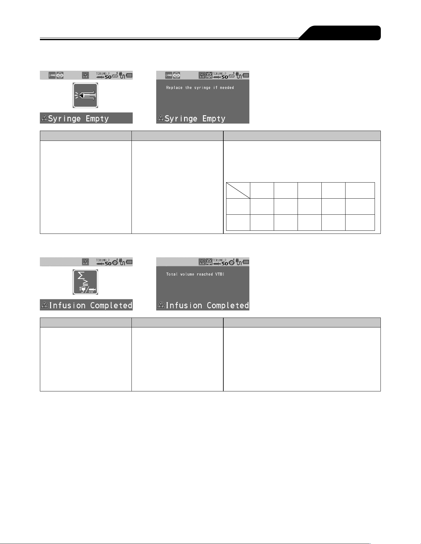
137
Troubleshooting
Syringe Empty
Occurrence Cause Action
LCD: The Syringe Empty
display flashes red.
Operation indicator: Flashes
red.
Buzzer: Activates.
Pump: Stops.
The syringe is fully pressed. Replace the syringe if you wish to continue the infusion.
(See page 62.) The time from full-press to alarm
sounding varies according to the product used. The
table below shows an example.
* When new TERUMO syringes are used.
5 mL
syringe
10 mL
syringe
20 mL
syringe
30 mL
syringe
50/60 mL
syringe
1 mL/h Approx.
3 min.
Approx.
11 min.
Approx.
30 min.
Approx.
41 min.
Approx.
64 min.
5 mL/h Approx.
1.0 min.
Approx.
2.5 min.
Approx.
5.0 min.
Approx.
8.5 min.
Approx.
12.0 min.
Completion alarm
Occurrence Cause Action
LCD: The Completion alarm
display flashes red.
Operation indicator: Flashes
green.
Buzzer: Activates.
Pump: Switches to the keep
vein open (KVO) function and
continues solution delivery.
The volume delivered has
reached the VTBI.
A normal operation when the VTBI is set.
Press the Stop switch to stop the KVO solution delivery.
(See page 57.)
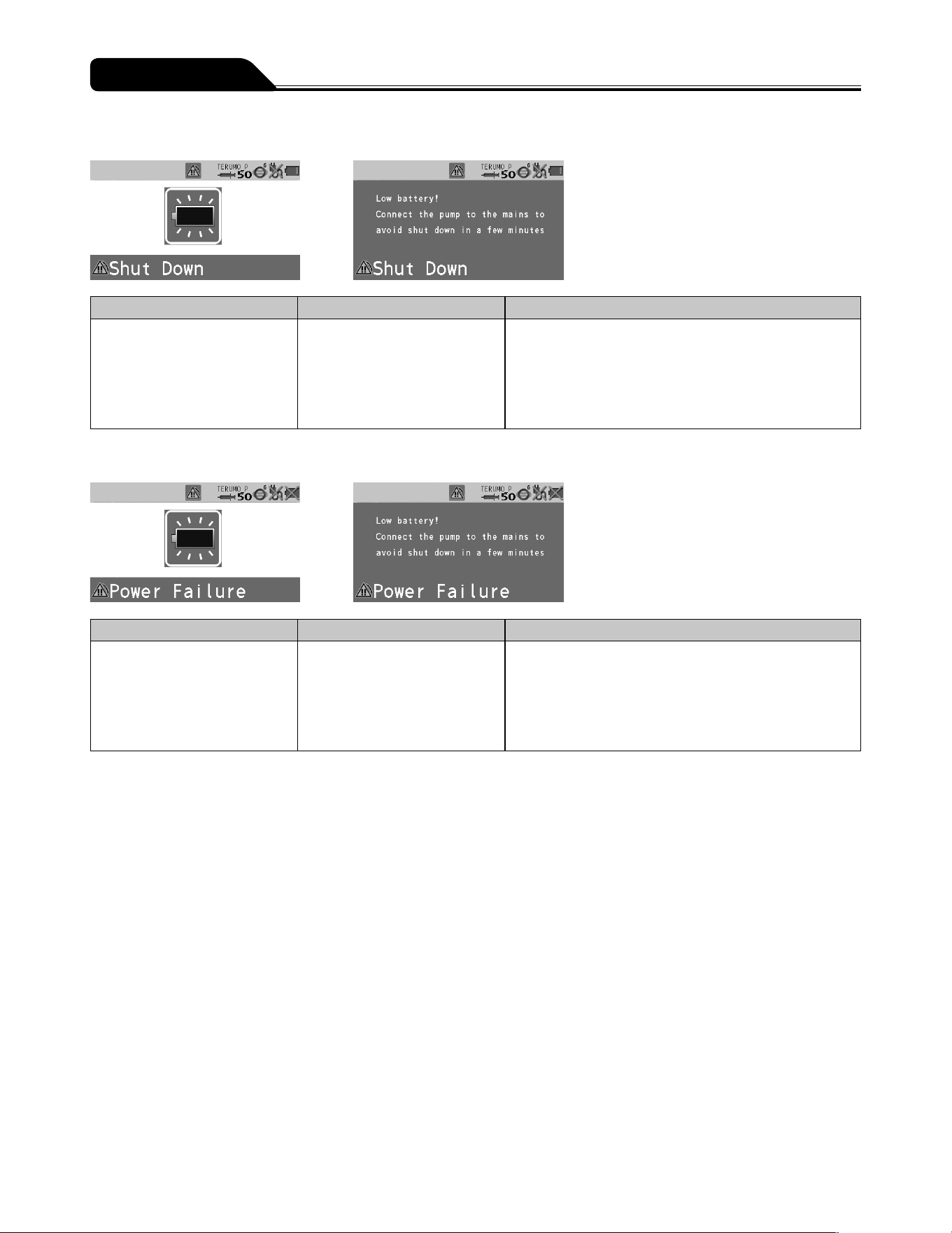
138
Troubleshooting
Shutdown Notice alarm
Occurrence Cause Action
LCD: The Shutdown Notice
alarm display flashes red.
Operation indicator: Flashes
red.
Buzzer: Activates.
Pump: Stops.
Battery has no power left. Connect immediately to the AC power supply or rack
system. (See page 29.)
* When using a rack system, see the instruction manual
of the rack system.
Power Failure alarm
Occurrence Cause Action
LCD: The Power Failure alarm
display flashes red.
Operation indicator: Flashes
red.
Buzzer: Activates.
Pump: Stops.
Two of the following causes have
occurred.
No AC power supply
Battery failure
Sub-battery failure or low
battery
Connect to the AC power supply and charge (8 hours or
more) with the power turned off.
If the problem still persists, contact TERUMO trained
service technicians.
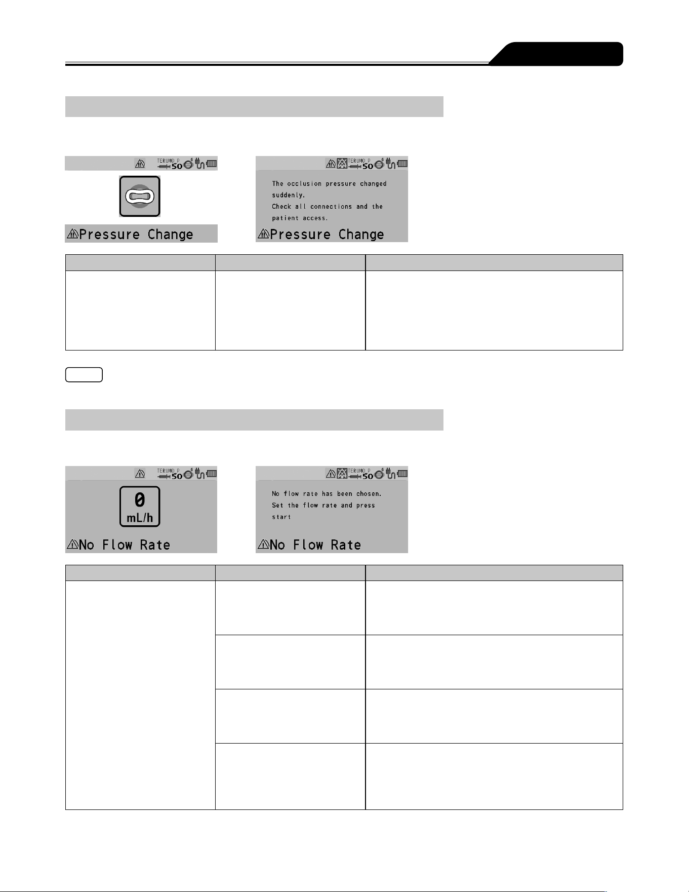
139
Troubleshooting
Medium priority alarm
Pressure alarm
Occurrence Cause Action
LCD: The Pressure alarm
display flashes yellow.
Operation indicator: Flashes
green.
Buzzer: Activates.
Pump: Delivers solution.
The internal pressure of
the infusion line has rapidly
increased or decreased.
Due to a possible fault in the infusion line or at the
puncture site, check for any fault. Stop the solution
delivery and eliminate the cause.
Note
This alarm is effective only when the Pressure alarm has been set in the drug library.
Low priority alarm
No Flow Rate alarm
Occurrence Cause Action
LCD: The No Flow Rate alarm
display lights up yellow.
Operation indicator: Off.
Buzzer: Activates.
Pump: Remains stopped.
The Start switch was pressed
without having set a flow rate.
Set a flow rate and press the Start switch to start
solution delivery. (See page 55.)
The flow rate setting exceeds
150 mL/h (for 5 mL syringe) or
300 mL/h (for 10, 20 or 30 mL
syringe).
Check the value set and re-set it to equal or less than
150 mL/h or 300 mL/h, depending on the syringe size
used. (See page 55.)
Some of the flow rate settings
do not apply to the advanced
dose or combination dose
mode.
Correct those settings and start solution delivery.
(See page 96. For the combination dose mode
setting, contact TERUMO trained service technicians.)
In the TCI mode, the target
concentration (Cpt or Cet) was
set to 0.0 and the Start switch
was pressed. (Except during
solution delivery)
Set the target concentration (Cpt or Cet) in the TCI
mode, then press the Start switch. (See page 35.)
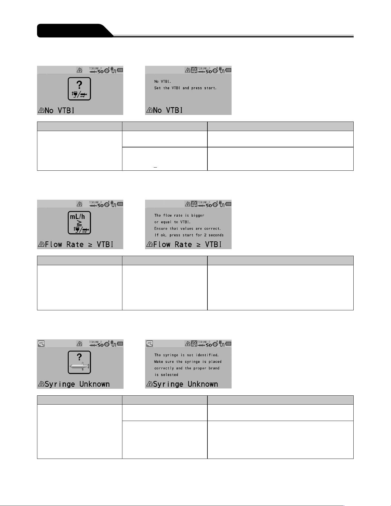
140
Troubleshooting
No VTBI alarm
Occurrence Cause Action
LCD: The No VTBI alarm
display lights up yellow.
Operation indicator: Off.
Buzzer: Activates.
Pump: Remains stopped.
The Start switch was pressed
without having set a VTBI.
Set a VTBI and press the Start switch to start solution
delivery. (See page 57.)
The Start switch was pressed
with the settings as volume
delivered > VTBI.
Clear the volume delivered (see page 64) or input a
new value in the VTBI (see page 57) and press the
Start switch to start solution delivery.
* Only if the VTBI setting function is enabled.
Flow Rate/VTBI Volume Judgment alarm
Occurrence Cause Action
LCD: The Flow Rate/VTBI
Volume Judgment alarm
display lights up yellow.
Operation indicator: Off.
Buzzer: Activates.
Pump: Remains stopped.
The Start switch was pressed
with the settings as Flow rate ≥
VTBI.
Check the setting values of the flow rate and VTBI
(if used). If they are not correct, input correct values
and press the Start switch to start solution delivery.
(See pages 55 and 56.) If they are correct, press
and hold the Start switch for 2 seconds or more to start.
* Only if the VTBI setting function is enabled.
Syringe Barrel Detection alarm
Occurrence Cause Action
LCD: The Syringe Barrel
Detection alarm display lights
up yellow.
Operation indicator: Off.
Buzzer: Activates.
Pump: Remains stopped.
The syringe in use does not
match the syringe brand set.
Check that the syringe brand setting matches the
syringe in use.
The clamp is still open.
The flange is not in the slit.
The syringe has not been set
at the center of the syringe
detector.
Place the syringe correctly.
(See pages 32 and 51.)
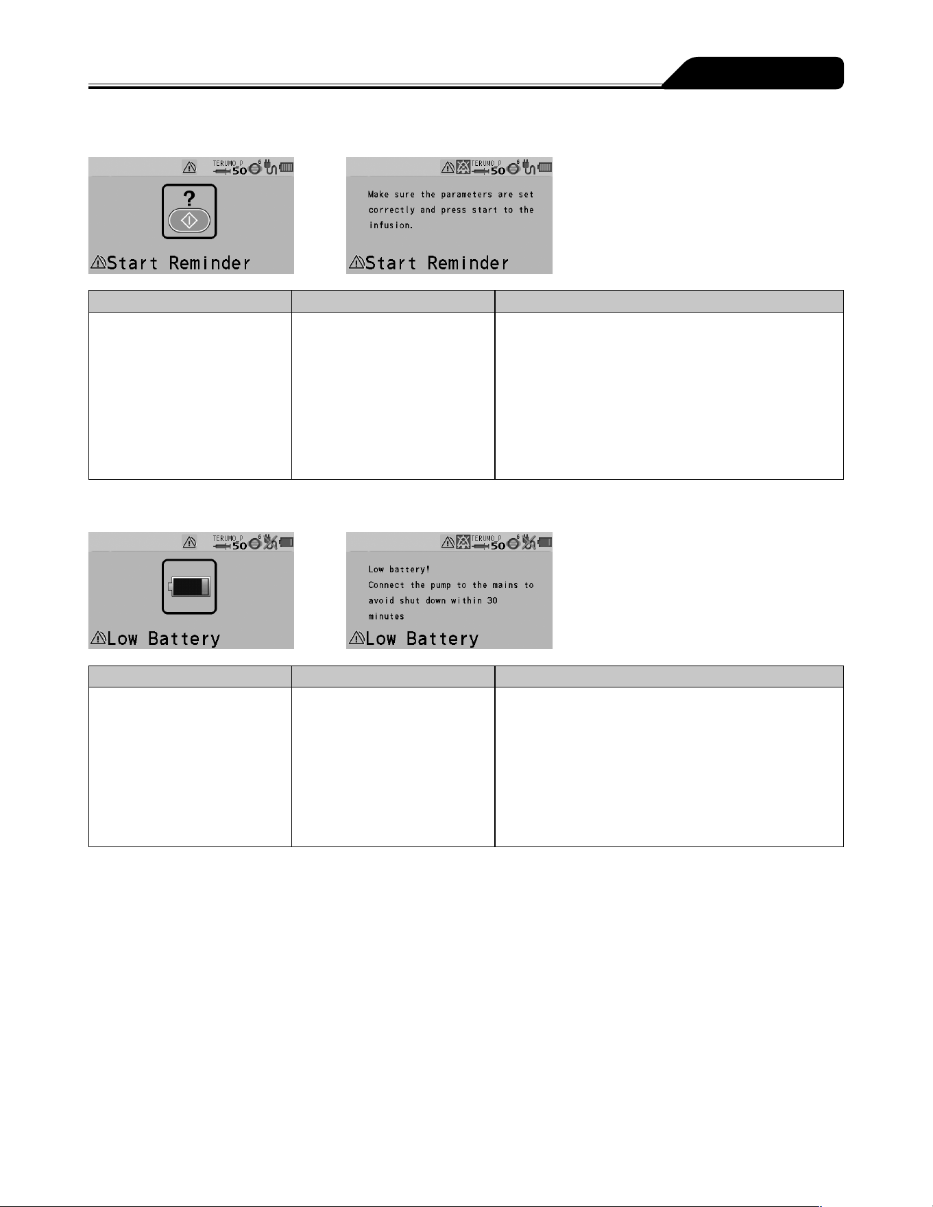
141
Troubleshooting
Start Reminder
Occurrence Cause Action
LCD: The Start Reminder
display lights up yellow.
Operation indicator: Off.
Buzzer: Activates.
Pump: Remains stopped.
In the TCI mode
After solution delivery, the
product has been left for 2
minutes or more after being
programmed.
In other dose modes
The product has been left for
2 minutes or more after being
programmed.
If you want to delay operation for a while, press and
hold the Back/Mute switch for 2 seconds or more to set
the equipment to standby mode. (See page 65.)
Check the setting values for flow rate and VTBI,
and press the Start switch to start solution delivery.
(See pages 55 and 56.)
Battery alarm
Occurrence Cause Action
LCD: The Battery alarm
display lights up yellow.
Operation indicator: Flashes
green (during solution delivery)
or off (stopped).
Buzzer: Activates.
Pump: Solution delivery
(during solution delivery) or
remains stopped (stopped).
Low battery capacity
(approximately 30 minutes),
battery level low or battery
energy is reducing.
Connect to the AC power supply or rack system.
(See page 29.)
* When using a rack system, see the instruction manual
of the rack system.
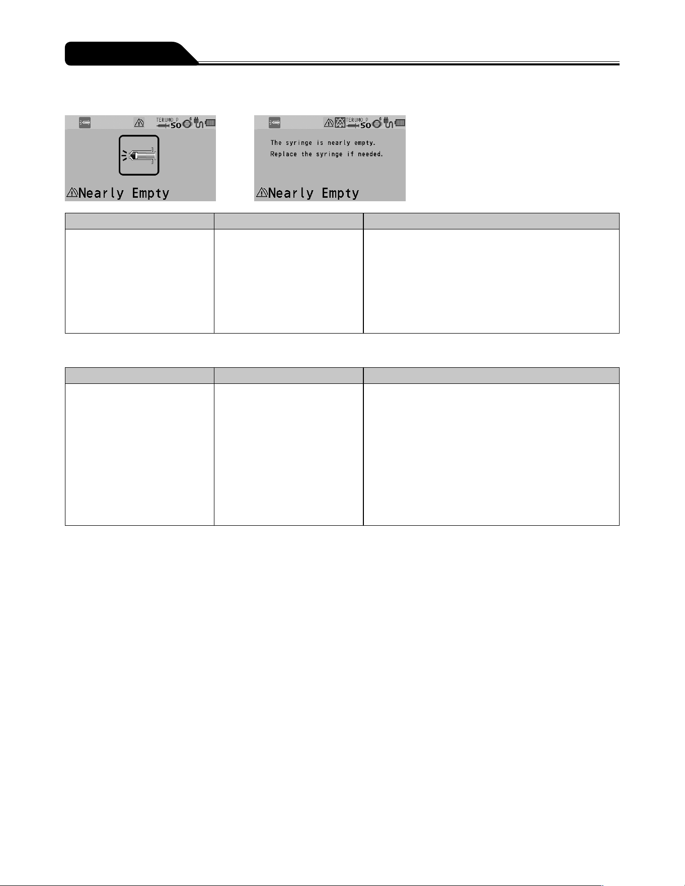
142
Troubleshooting
Nearly Empty alarm
Occurrence Cause Action
LCD: The Nearly Empty alarm
display lights up yellow.
Operation indicator: Flashes
green (during solution delivery)
or off (stopped).
Buzzer: Activates.
Pump: No change to the
status.
The quantity of the drug
solution is low.
If you want to continue the solution delivery, replace the
syringe. (See page 62.)
Re-alarm
Occurrence Cause Action
LCD: The respective alarm
displays flash/light up (the
flashing/light up colours are
the same as those at the
respective alarms).
Operation indicator: Same as
for when the alarms are first
activated.
Buzzer: Activates.
Pump: No change to the
status.
Operation was not started
within 2 minutes after the
alarm was muted.
Follow the corrective action of each alarm.
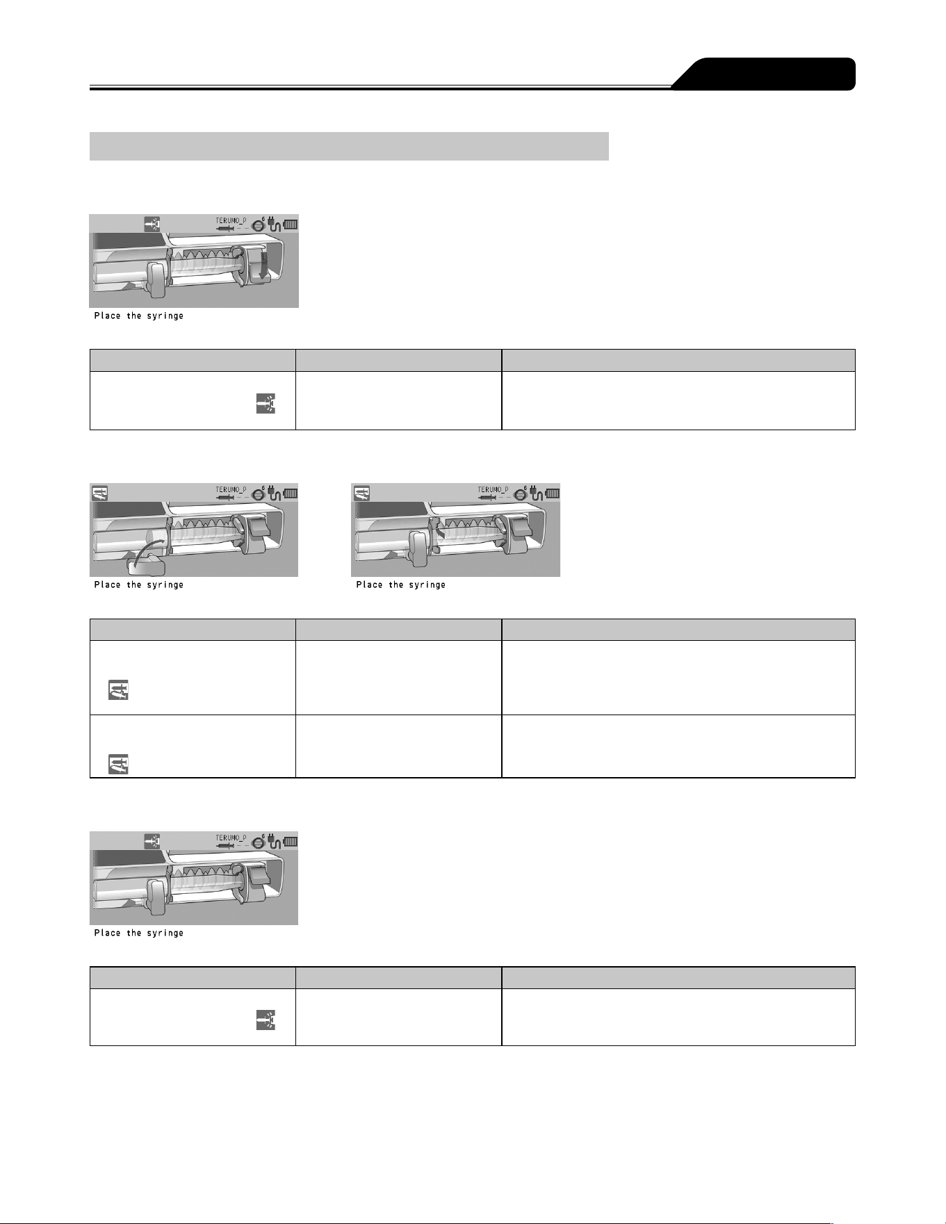
143
Troubleshooting
Other problems
When installing a syringe: Plunger displaced
Occurrence Cause Action
LCD: [Place the syringe.]
Slider displacement icon
flashes.
The plunger has been
displaced.
Place the syringe correctly. (See pages 32 and 51.)
When installing a syringe: Syringe displaced
Occurrence Cause Action
LCD: [Place the syringe.]
Syringe displacement icon
flashes.
The clamp is still open.
The flange is not in the slit.
The syringe is not installed
correctly.
Place the syringe correctly. (See pages 32 and 51.)
LCD: The Syringe
displacement icon
flashes.
The syringe brand setting is
incorrect.
Check that the syringe brand setting matches the brand
of the syringe to be set.
When installing a syringe: Slider displacement
Occurrence Cause Action
LCD: [Place the syringe.]
Slider displacement icon
flashes.
The slider has been displaced. Place the syringe correctly.
(See pages 32 and 51.)
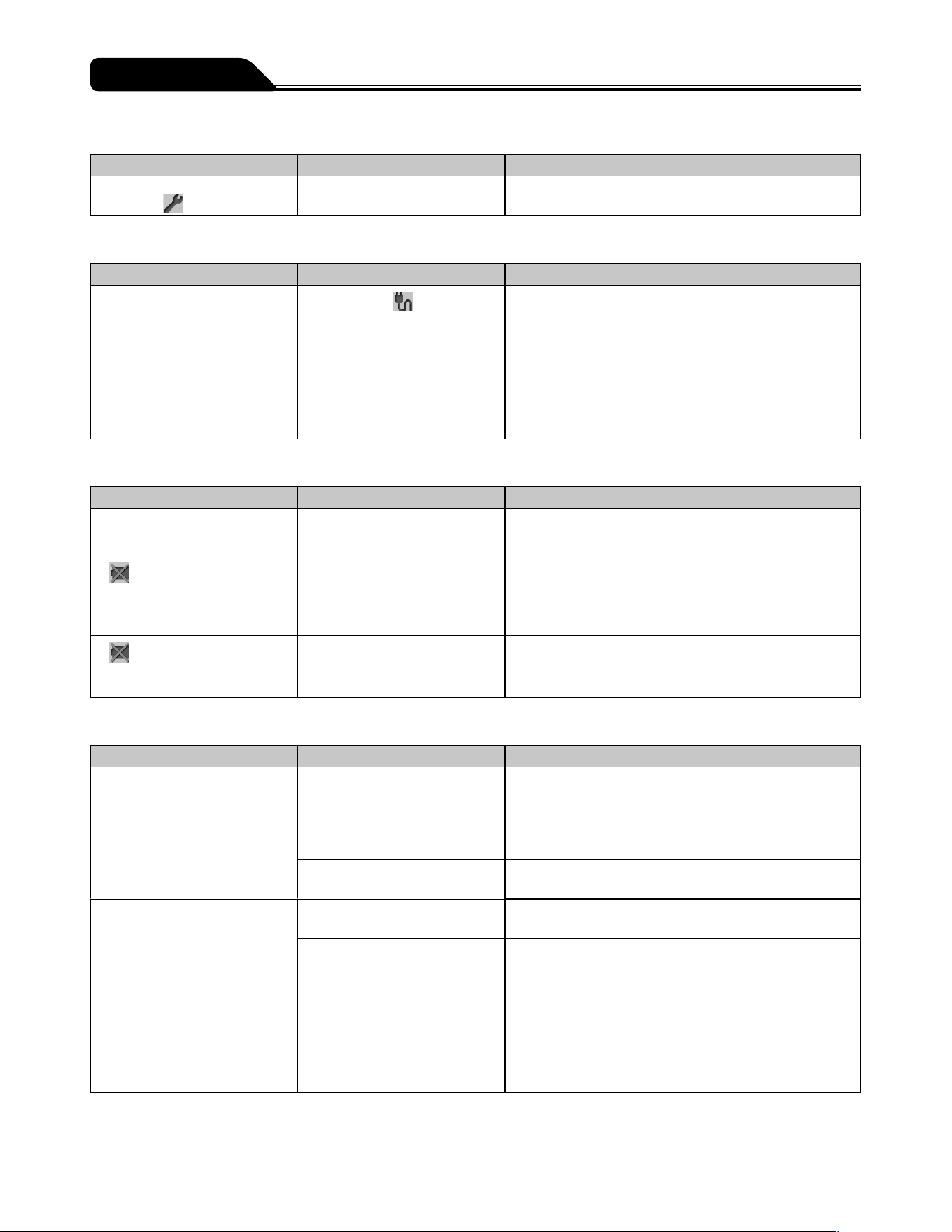
144
Troubleshooting
Maintenance timer
Occurrence Cause Action
The Maintenance timer
indicator
lights up.
It is time to perform
maintenance.
Contact TERUMO trained service technicians.
AC power detector function
Occurrence Cause Action
The pump cannot be turned on
when using AC power.
The AC icon
is not
displayed even after the AC
power cable is connected.
Check the connection of the AC power cable to the
pump and the power supply. (See page 29.)
The AC power cable is
damaged.
The AC power cable is
internally disconnected.
Replace the AC power cable.
Battery Replacement Time/Failure alarm
Occurrence Cause Action
The battery operation time is
short even after fully charged.
The battery icon
is displayed.
The battery icon does not
display 5 bars after charging
for 8 hours or more.
The battery has deteriorated
or is damaged.
Replace the internal battery.
and the battery charge
level appear alternately after
more than 8 hours of charging.
The sub-battery has
deteriorated or is damaged.
Replace the sub-battery.
Flow rate
Occurrence Cause Action
Pressing the Start switch does
not start solution delivery.
The infusion line is not open.
The syringe is not installed
correctly.
1. Replace the syringe correctly.
(See pages 32 and 51.)
2. Prime the line, ensuring that the plunger is kept in the
slider to prevent the solution from being delivered to
the patient. (See pages 38 and 58.)
An occlusion has occurred in
the infusion line.
Eliminate the cause of occlusion. (See page 136.)
Flow rate accuracy is low. Syringe has not been installed
correctly.
Check the setting of the syringe.
(See pages 32 and 51.)
The syringe in use does not
match the syringe brand set on
the pump.
Check that the syringe brand setting matches the brand
of the syringe in use.
The flow rate is not set
correctly.
Correct the flow rate setting.
There is large height
difference between the pump
and patient.
Adjust the patient to the pump height differential.
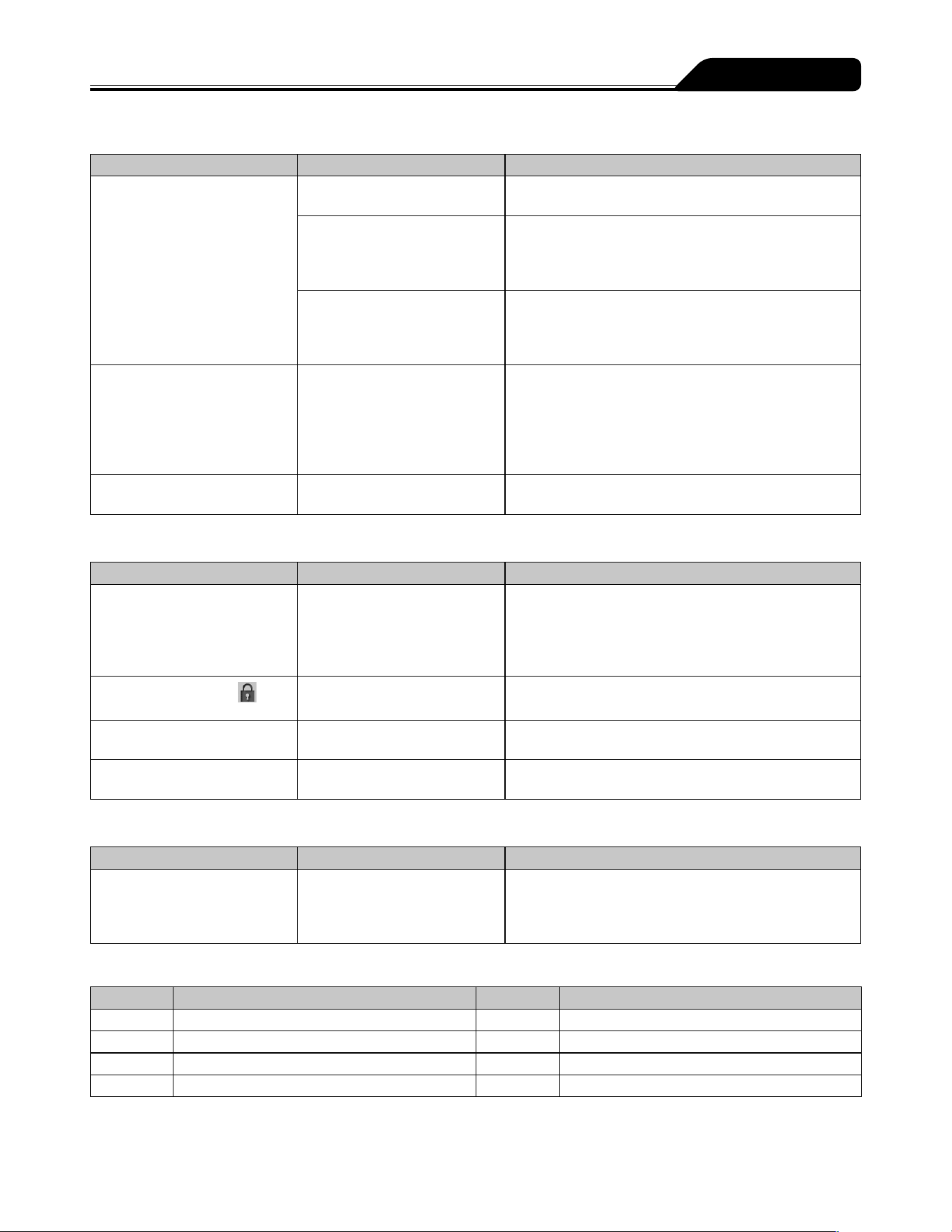
145
Troubleshooting
External communication
Occurrence Cause Action
Cannot communicate (IrDA) The infrared communication
window is dirty.
Clean the infrared communication window with cotton
swabs or gauze, etc.
The pump is not securely
attached to the TERUFUSION
Communication Rack System.
Make sure that the TERUFUSION Communication Rack
System is securely attached to the pump.
See the instruction manual of the TERUFUSION
Communication Rack System.
The TERUFUSION
Communication Rack System
is not turned on.
Turn on the TERUFUSION Communication Rack
System.
See the instruction manual of the TERUFUSION
Communication Rack System.
Cannot communicate (wireless
LAN)
SSID, encryption setting, IP
address, subnet mask, default
GW, connection destination
IP address, communication
port, or device ID may not be
suitable.
Check the settings of the product or the connected
device. (See page 118.)
Signal strength icon (Colour =
Grey, No signal bar) flashing
The pump is defective. Contact TERUMO trained service technicians.
Display
Occurrence Cause Action
The LCD is dim. The equipment is operated
using the internal battery
The equipment is in the night
mode. (When the night mode
is enabled)
The brightness becomes two levels lower during
internal battery operation or night mode operation.
If it is not the case, contact TERUMO trained service
technicians.
The keypad lock icon
is
displayed.
The keypad lock is on. Press and hold the Back/Mute switch for 2 seconds or
more to release the keypad lock.
Displays are irregular and the
buzzer sounds.
The pump is defective. Contact TERUMO trained service technicians to
request repair.
The power turns off
unexpectedly.
The pump is defective. Contact TERUMO trained service technicians to
request repair.
Failure
Occurrence Cause Action
E* is displayed, the operation
indicator lights up red and the
buzzer sounds.
(* is alphanumeric characters.)
The pump is defective. Turn off the power and contact TERUMO trained
service technicians to request repair.
Error Code Table
Display Error Display Error
E1 Internal electronic circuit fault E5* Internal electronic circuit fault
E2* Internal electronic circuit fault E8* Operation key fault
E3 Motor fault E10* Internal electronic circuit fault
E4* Internal electronic circuit fault
(* is alphanumeric characters.)

146
Thiết bị chính
Tên sản phẩm Bơm tiêm điện gây mê tĩnh mạch có kiểm soát nồng độ đích TCI
Model TE-SS830P
Mã hàng
TE
*
SS835Pxx
Bơm tiêm tương thích Bơm tiêm vô trùng được chỉ định cho dùng chung và bơm tiêm có sẵn dịch.
Cỡ bơm tiêm
5 mL, 10 mL, 20 mL, 30 mL, 50/60 mL
Nhãn hiệu bơm tiêm TERUMO hoặc các nhãn hiệu khác
Chế độ liều mL/h
μg/kg/min*
mg/kg/h*
mg/kg/h+DIPRIVAN*
Thư viện
TCI
* Có thể kích hoạt hay không kích hoạt
Ngưỡng cài đặt tốc độ Ngưỡng cài đặt
0.01 đến 150.00 mL/h
Lưu ý, giới hạn trên của tốc độ có thể thay đổi như sau:
0.01 đến 150.00 mL/h (khi sử dụng bơm tiêm 5 mL)
0.01 đến 300.00 mL/h (khi sử dụng bơm tiêm 10, 20, 30 mL)
0.01 đến 1200.00 mL/h (khi sử dụng bơm tiêm 50/60 mL)
Bước đặt
0.01 mL/h ( 0.01 đến 10.00 mL/h)*
0.10 mL/h ( 10.00 đến 100.00 mL/h)*
1.00 mL/h 1( 00.00 đến 1200.00 mL/h)*
*: Có thể dùng các bước đặt này khi cài đặt tốc độc bằng núm xoay
(Giá trị là 0.00 mL/h khi bật nguồn.)
Ngưỡng cài đặt VTBI 0.10 đến 100.00 mL (bước đặt 0.10 mL)
100.00 đến 9999.00 mL (bước đặt 1.00 mL)
Khi cài đặt liều ở đơn vị khối lượng, có thể cài đặt đơn vị khối lượng
(Ngưỡng cài đặt: 0.01 ng đến 9999.99 kg)
----.-- (Không giới hạn)
(Giá trị là 0.00 mL khi bật nguồn)
Ngưỡng cài đặt thời gian VTBI
1 phút đến 99 giờ 59 phút (bước đặt 1 phút)
-- --n step (Không giới hạn)
Ngưỡng cài đặt liều 0.01 đến 10.00 (bước đặt 0.01)
10.00 đến 100.00 (bước đặt 0.10)
100.00 đến 999.00 (bước đặt 1.00)
(Ở đơn vị như μg/kg/min và mg/kg/h ...)
(Giá trị là 0.00 khi bật nguồn.)
Ngưỡng cài đặt cân nặng 0.1 đến 300.0kg (bước đặt 0.1kg)
Ngưỡng cài đặt nồng độ pha loãng
0.01 đến 10.00 (bước đặt 0.01)
10.00 đến 100.00 (bước đặt 0.10)
100.00 đến 999.00 (bước đặt 1.00)
(Ở đơn vị như mg/mL ...)
Ngưỡng cài đặt lượng thuốc
0.01 đến 10.00 (bước đặt 0.01)
10.00 đến 100.00 (bước đặt 0.10)
100.00 đến 999.00 (bước đặt 1.00)
(Ở đơn vị như μg and mg ...)
Specifications

147
Specifications
Ngưỡng cài đặt lượng dịch
0.01 đến 10.00 (bước đặt 0.01)
10.00 đến 100.00 (bước đặt 0.10)
100.00 đến 999.00 (bước đặt 1.00)
(Đơn vị: mL)
Ngưỡng cài đặt truyền TCI Nồng độ đích trong máu/ trong não (Cpt/Cet)
Nồng độ pha loãng
Propofol : 0.0 đến15.0 μg/mL (bước đặt 0.1 μg/mL)
Remifentanil : 0.0 đến 50.0 ng/mL (bước 0.1 ng/mL )
Propofol : 1%, 2%
Remifentanil :
0.1 đến 100.0 μg/mL (bước 0.1 μg/mL)
100.0 đến 500.0 μg/mL (bước 1.0 μg/mL )
Propofol : 16 đến 100 (bước đặt 1 tuổi)
Remifentanil : 12 đến 100 (bước đặt 1 tuổi)
100 đến 250 cm (bước đặt 1 cm)
30 đến 200 kg (bước đặt 0.1 kg)
0.0 đến 1200.0 mL/h (bước đặt 0.1 mL/h)
Hiển thị lượng dịch đã tiêm
0.0 đến 9999.0 mL (bước đặt 0.1 mL)
Tuổi
Chiều cao
Cân nặng
Hiển thị tốc độ
Hiển thị liều
0.00 đến 999.00 mg/kg/h (bước đặt 0.01)
0.00 đến 999.00 μg/kg/min (bước đặt 0.01)
Hands On Bolus flow rate setting range 100.00 mL/h (when using syringe of 5 mL)
100.00 to 300.00 mL/h (when using syringe of 10 mL, 20 mL, 30 mL)
100.00 to 1200.00 mL/h (when using syringe of 50/60 mL)
(100.00 mL/h step)
Hands Free Bolus dose rate setting range 0.01 to 10.00 (0.01 step)
10.00 to 100.00 (0.10 step)
100.00 to 999.00 (1.00 step)
(In units such as mL and mg/kg etc.)
Hands Free Bolus dose time setting range 1 s to 60 min 00 s (1 s step)
Volume delivered display range 0.00 to 10.00 mL (0.01 mL step)
10.00 to 100.00 mL (0.10 mL step)
100.00 to 9999.00 mL (1.00 mL step)
When the dose rate is set in mass units, the volume is expressed in mass units.
(Volume delivered display range: 0.01 ng to 9999.99 kg)
(It will be 0.00 mL when the power is turned on.)
Flow rate
accuracy
Machine accuracy Within ±1% (flow rate ≥ 1.00 mL/h)
Accuracy including
syringe
Within ±2%
(The hourly precision after one hour has passed since the start of solution
delivery, in the case where water or a physiological saline solution is used with
a TERUMO 50/60 mL syringe made in the Philippines (TERUMO_P) at a flow
rate of 1.00 mL/h or more (ambient temperature: 23±2°C) according to IEC
60601-2-24:2012 (EN 60601-2-24:2015) standard.)
Within ±3%
(The hourly precision after one hour has passed since the start of infusion at a
constant flow rate of 1.00 mL/h or more according to IEC 60601-2-24:2012 (EN
60601-2-24:2015) standard.) (For the accuracy of the 50 mL VACCINE syringe,
refer to page 24)
Occlusion detection pressure 10 to 120kPa (set value)
The occlusion detection pressure can be set in 10 levels.
Purge flow rate Approx. 150 mL/h (when using syringe of 5 mL)
Approx. 300 mL/h (when using syringe of 10 mL)
Approx. 400 mL/h (when using syringe of 20 mL)
Approx. 500 mL/h (when using syringe of 30 mL)
Approx. 1200 mL/h (when using syringe of 50/60 mL)

148
Specifications
Alarms Occlusion alarm, Pressure alarm*
2
, Nearly Empty alarm, Slider Displacement
alarm, Syringe Barrel Detection alarm, Syringe Displacement alarm, Plunger
Displacement alarm, Battery alarm, Re-alarm, Shutdown Notice alarm, Power
Failure alarm, Start Reminder, No Flow Rate alarm, No VTBI alarm*
1
, Flow
Rate/VTBI Volume Judgment alarm*
1
, Completion alarm*
1
, Link Interruption
alarm*
2
.
*
1
: Only if the VTBI setting function is enabled (except the TCI mode) (Default:
disabled).
*
2
: Except the TCI mode
Safety functions Remaining volume
detection setting
function
Sets the Nearly Empty alarm position based on the time before the syringe is
empty.
Occlusion detection
pressure select function
Selects the occlusion detection pressure setting values in 10 levels.
Bolus reduction
function
When an occlusion occurs, the slider is drawn back to reduce internal pressure.
Flow rate range setting
function A
(Soft limits)
The flow rate setting range can be controlled within the flow rate setting range
prescribed for each type of syringe (brand, size).
When you try to set a value outside the range controlled by this function, a
message asking for confirmation is displayed.
If you confirm the setting, you can set the value which is outside the
controlled range and the display colour of the value changes.
Flow rate range setting
function B
(Hard limits)
The flow rate setting range can be controlled within the flow rate setting range
prescribed for each type of a syringe.
Values outside the range controlled by this function cannot be set.
Keypad lock function Disables switch operations. However, the Start switch, the keypad lock function
disable operation (press and hold the Back/Mute switch), and the Power switch
still function. When an alarm is activated, the keypad lock is released.
Available
Functions
Syringe installation
guidance function
Displays a screen that indicates the syringe installation status on the LCD.
Syringe brand display
function
Displays the syringe brand and size on the LCD.
Syringe type switch
function
Switching syringes is possible by performing the specified operation after the
power is turned on.
VTBI setting function Sets the VTBI of dosage of drug solution.
VTBI time setting
function
Sets the VTBI time of dosage of drug solution.
Purge buzzer sound
function
When the Purge switch is being pressed, the buzzer sounds.
Bolus buzzer sound
function
During a bolus, the buzzer sounds.
Volume delivered clear
function (except the TCI
mode)
Clears the volume delivered display to zero.
Standby function By pressing and holding the Back/Mute switch, the pump can be put in standby
mode. In the standby function, the Start Reminder is delayed.
Standby duration time
select function
Changes the time to activate a Start Reminder in the standby mode.
Buzzer volume select
function
Changes the buzzer volume.
Switch operation
buzzer sound function
Buzzer sounds when a switch operation is performed.

149
Specifications
Available
Functions
Stop transition buzzer
sound function
Buzzer sounds when the Stop switch is pressed during solution delivery.
LCD brightness select
function
Changes the LCD brightness.
Maintenance timer
function
Time to next maintenance check can be set. That information is displayed on
the LCD.
Date and time setting
function
Sets the date and time.
Free message function Displays a message on the pump via communication.
External
communication
function (infrared
communication (IrDA))
Allows communication with the optional TERUFUSION Communication Rack
System to output the status of the pump (flow rate, alarms, etc.) via infrared.
External
communication
function (wireless LAN)
Allows communication with a network system to output the status of the pump
(flow rate, alarms, etc.) via wireless LAN.
History function Displays the operation history, etc.
AC power detector
function
Detects the presence or absence of AC power supply to the pump and displays
that status.
AC power detector
buzzer sound function
Buzzer sounds when AC power supply is provided to or disconnected from the
pump.
Purge volume upper
limit setting function
Sets the upper limit of the purge volume.
Bolus volume upper
limit setting function
Sets the upper limit of the hands on bolus volume.
Keep Vein Open
Function
After activation of the Infusion Completion alarm, solution delivery is continued
at the keep vein open flow rate.
Keep Vein Open flow
rate select function
Changes the keep vein open flow rate.
During-start volume
delivered clear function
(except the TCI mode)
Clears the volume delivered to zero during solution delivery.
During-start flow rate/
dosage rate change
function
Changes the flow rate/dosage rate during solution delivery.
Selecting dose mode
during the solution
delivery function
Change the dose mode from mL/h to another mode during solution delivery.
Set value memory
function
Saves the current set values (e.g. flow rate, VTBI, dosage and weight) before
the power is turned off.
Alarm melody select
function
Changes the buzzing pattern (melody) of the alarm buzzer.
Setting dial
acceleration function
Rotating the Dial while pressing the Stop switch accelerates the setting rate to
set items such as the flow rate.
Hands On Bolus
function
After the bolus flow rate is set, a bolus is delivered while the Purge switch is
pressed.
Hands Free Bolus
function
When bolus volume and bolus time are set, the flow rate is calculated and a
bolus is delivered.
Shortcut call function Press multiple keys in combination to directly call the bolus flow rate setting
display.
Night mode function Changes the LCD brightness for a specified time period.

150
Specifications
Available
Functions
Power OFF buzzer
sound function
Buzzer sounds as the power is turned off.
Dose mode select
function
The dose mode can be selected among mL/h, μg/kg/min, mg/kg/h,
mg/kg/h+DIPRIVAN, TCI, and drug library.
Start-up dose mode
select function
The initial dose mode after the power is turned on can be selected from mL/h,
μg/kg/min, mg/kg/h, mg/kg/h+DIPRIVAN, TCI, and drug library.
Dose mode information
display function
When the AC power cable is connected, the versions of TCI and drug library,
and profile name are displayed before the power is turned on.
Menu1 (User mode1)
shortcut function to
dose mode
Enable to go directly to the dose mode select display when the menu screen is
selected.
Drug/patient
information display
function
Displays drug information such as dilution, patient information including
patient name, age, gender, weight, height, etc. The dilution and weight can be
changed.
Dilution setting
function by amount and
solution
Selects how to specify the dilution from either Dilution or Amount/Solution.
Interval/Intermittent
dose function
The specified dosage rate is delivered at the specified regular intervals.
Multi-step dose
function
The speed of solution delivery increases or decreases at the specified levels
(up to 10 levels).
Delayed Start dose
function
Solution delivery starts after the specified time has elapsed.
Link function (Switch
function A, B)
Switch function A: Operations of two pumps are linked. When a Completion
alarm occurs on the first pump, the second pump starts
solution delivery.
Switch function B: Interlocks two pumps. Starts solution delivery of the first
pump, and then starts solution delivery of the second pump
at the time set in advance or afterwards. After solution
delivery of the second pump is started, each pump changes
the solution delivery speed according to respective settings.
The interlock of the pumps finishes upon completion of the
set solution delivery or at alarm timing.
Come and See ME
function
Automatic call function after a specified time elapses.
Volume delivered unit
select function
Switches the unit of volume delivered appearing in the drug library mode, the
μg/kg/min mode, the mg/kg/h mode, the mg/kg/h+DIPRIVAN mode, and the
TCI mode.
Micro notation select
function
Switches the unit between μg and mcg appearing in the drug library mode,
the μg/kg/min mode, the mg/kg/h mode, the mg/kg/h+DIPRIVAN mode, and the
TCI mode.
Graph display function
(TCI mode only)
Displays the chronological time-lapse change of TCI infusion in graphs.
The graph scale is adjusted accordingly as the time lapse when the relevant
mode is selected.
Calculated plasma
concentration display
function (TCI mode
only)
Displays the predicted plasma concentration of drug in the TCI mode.
Effect-site
concentration display
function (TCI mode
only)
Displays the predicted effect-site concentration of drug in the TCI mode.
Maximum flow rate
setting (TCI mode only)
The maximum flow rate in the TCI mode can be set.

151
Specifications
Available
Functions
Plasma limit setting
(TCI mode only)
The upper limit of plasma concentration can be set for effect-site TCI.
Decrement time display
function (TCI mode
only)
Displays the predicted time when the decrement concentration of drug level
(set by users) is reached in the TCI mode.
During-start target
concentration select
function (TCI mode
only)
The target concentration (Cpt or Cet) can be changed during solution delivery.
Use conditions Temperature: 5 to 40°C
Humidity: 20 to 90%RH (non-condensing)
Atmospheric pressure: 70 to 106kPa (700 to 1060hPa)
Storage conditions* Temperature: -20 to 45°C
Humidity: 10 to 95%RH (non-condensing)
Atmospheric pressure: 50 to 106kPa (500 to 1060hPa)
Transport conditions Temperature: -20 to 60°C
Humidity: 10 to 95%RH (non-condensing)
Atmospheric pressure: 50 to 106kPa (500 to 1060hPa)
Power supply AC100 to 240V, 50 to 60Hz
Battery: Lithium ion battery
Continuous use period: Approx. 8 hours (applies when solution is delivered
continuously at 5 mL/h in ambient temperature of
25°C with new fully charged battery)
Charging time: ≥8 hours (when charged with AC power supply with
the power turned off)
The battery can be charged to approx. 80% in
3 hours.
Sub-battery: Nickel-metal-hydride battery (for a Power Failure alarm in case of
both power supplies are lost)
Charging time: ≥8 hours (when charged with a new battery and AC power
supply in ambient temperature of 25°C when the power is off)
Power consumption 26VA
Classification Electric shock
protection
Class I equipment and internally powered equipment, Defibrillation-proof type
CF applied part
Mode of operation
Continuous operation
Protection against
harmful ingress of
water or particulate
matter
IP24
Wireless LAN Hereby, TERUMO CORPORATION declares that this TERUFUSION Syringe
Pump Type SS3 OTCI is in compliance with the essential requirements and
other relevant provisions of Directive 2014/53/EU.
Transmit frequency or frequency band: 2412 to 2472 MHz
Type of modulation and frequency characteristics:
DSSS (Direct Sequence Spread Spectrum)
OFDM (Orthogonal Frequency-Division Multiplexing)
Effective radiated power:
IEEE802.11b 15dBm
IEEE802.11g 13dBm
IEEE802.11n 12dBm
* A state in which the equipment is unpacked and stored for subsequent use with the main power supply unplugged.

152
Specifications
Dimensions 381 mm (W)*
1
x 120 mm (H)*
1
x 112 mm (D)*
2
*
1
: Excluding protrusions
*
2
: Excluding protrusions, pole clamp and moving range
Unit Weight Approx. 2.0 kg
Standard accessories AC power cable, pole clamp (Screw type), instruction manual
This product is in compliance with EMC (electromagnetic compatibility) standard IEC 60601-1-2:2007 (EN 60601-1-2:2007)
(CISPR group classification and class classification are Group 1 and Class B) and IEC 60601-1-2:2014 (EN 60601-1-2:2015)
(CISPR group classification and class classification are Group 1 and Class A). It is also in compliance with the EMC level
required by IEC 60601-2-24:2012 (EN 60601-2-24:2015).
Conformity standard and directive
IEC 60601-1:2005+A1:2012 (EN 60601-1:2006+A1:2013)
IEC 60601-1-2:2007 (EN 60601-1-2:2007)
IEC 60601-1-2:2014 (EN 60601-1-2:2015)
IEC 60601-1-6:2010+A1:2013 (EN 60601-1-6:2010+A1:2015)
IEC 60601-1-8:2006+A1:2012 (EN 60601-1-8:2007+A1:2013)
IEC 60601-2-24:2012 (EN 60601-2-24:2015)
MDD (Medical Device Directive) 93/42/EEC (Class IIb)
Note
If an AC power cable is not included with the pump unit, please contact TERUMO trained service technicians to receive the cable
suited for your region.
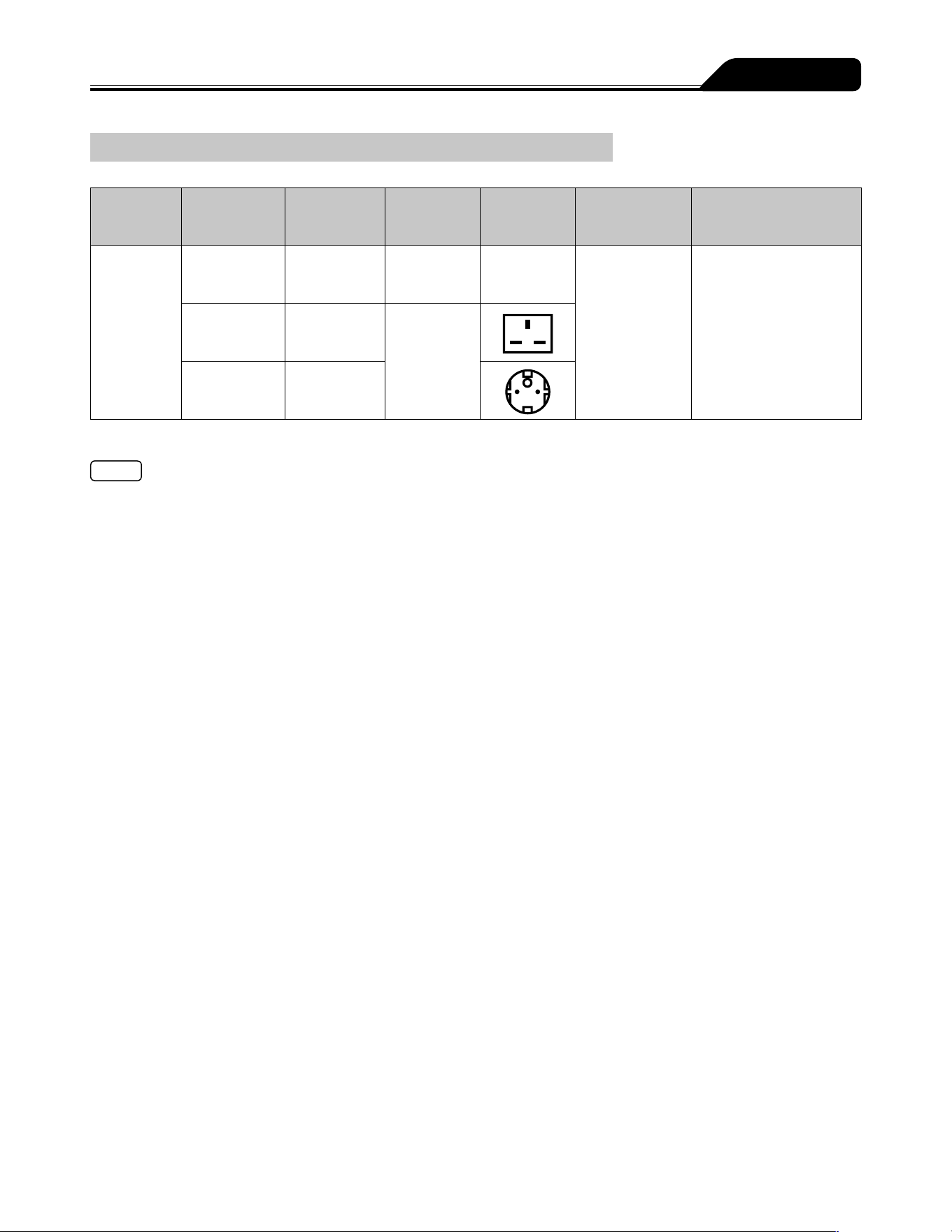
153
Specifications
Units Available
Model
Mã hàng
Loại ổ cắm
Dòng điện
Loại ổ cắm
Giao diện
máy tính
Weight mode,
Drug library mode
TE-SS830P
TE
*
SS835P01
Giao tiếp hồng
ngoại (IrDA),
LAN không dây
Có*
TE
*
SS835P02
UK type
100 to 240V
TE
*
SS835P03
European type
* Chế độ cân nặng chỉ có khi được kích hoạt bởi cài đặt bên trong tương ứng.
Notes
Separate setup procedures are required for the product with voltage-plug combinations other than listed above.
If an AC power cable is not included with the pump unit, please contact TERUMO trained service technicians to receive the cable
suited for your region.
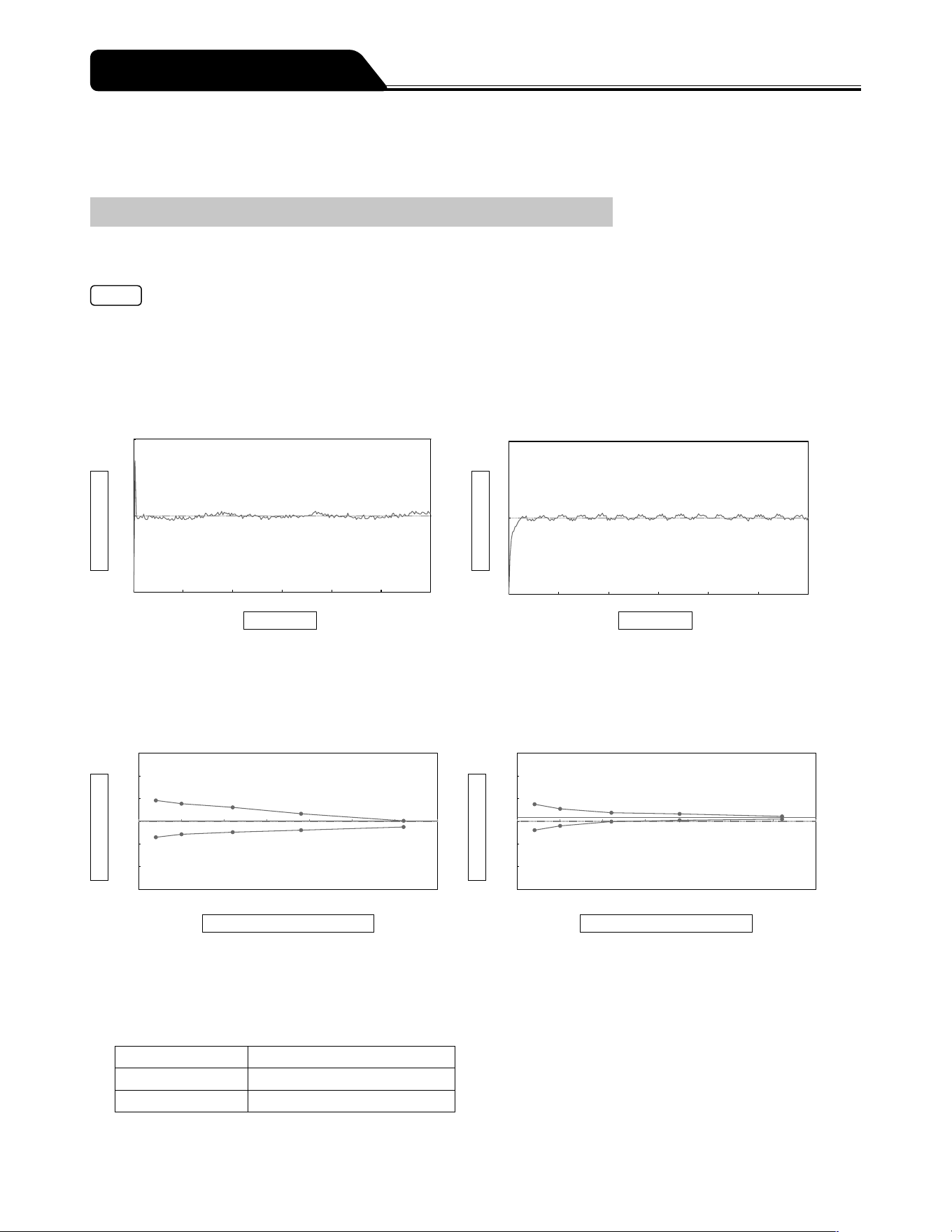
154
Test data for flow rate characteristics and occlusion characteristics is shown below.
Tests were conducted based on IEC 60601-2-24:2012 (EN 60601-2-24:2015). For details, refer to IEC 60601-2-24:2012 (EN 60601-
2-24:2015).
Flow Rate Characteristics
Start-up curves and trumpet curves, which are used as typical explanations of flow rate characteristics, are shown. The data below
is representative examples measured for flow rates of 1 mL/h and 5 mL/h with a new TERUMO syringe (50 mL).
Note
Flow rate characteristics are correlated with the syringe. Depending on the combination of syringe and pump, the same data as
the representative example may not be obtained.
1. Start-up curve
The discharge quantity measured every 30 seconds for a 2-hour measurement period is converted into flow rate values is
shown. These graphs show characteristics from immediately after the start of solution delivery to when flow rate has stabilized.
<Flow rate: 1 mL/h>
2
1
0
0 20 40 60 80 100 120
Flow rate(mL/h)
Time (min)
<Flow rate: 5 mL/h>
10
5
0
0 20 40 60 80 100 120
Flow rate(mL/h)
Time (min)
2. Trumpet curve
Data for the latter one hour of the 2-hour measurement period is shown, with the horizontal axis showing the observation
window time (minutes) and the vertical axis showing the maximum and minimum flow rate error for each observation window.
The narrower the region enclosed between the top and bottom solid lines (the so-called trumpet curve) is, the less pulsatory
motion there is.
<Flow rate: 1 mL/h>
+15%
+10%
+5%
+0%
-5%
-10%
-15%
0 5 10 15 20 25 30 35
Flow rate error (%)
Observation window time (min)
Flow rate error = +0.09% <Flow rate: 5 mL/h>
+15%
+10%
+5%
+0%
-5%
-10%
-15%
0 5 10 15 20 25 30 35
Flow rate error (%)
Observation window time (min)
Flow rate error = +0.86%
3. Influence of pressure on the lower side of the pump (back pressure) on flow rate accuracy
The table below shows the maximum deviation of flow rate accuracy under normal condition with either -13.3kPa or 13.3kPa of
back pressure.
-13.3kPa (13.3kPa) of back pressure is equivalent to the condition where the pump is located approx. 136 cm higher (lower)
than the patient (in the case of water).
Back pressure (kPa) Maximum deviation of values (%)
-13.3 +1.0
+13.3 -0.7
Device Characteristics
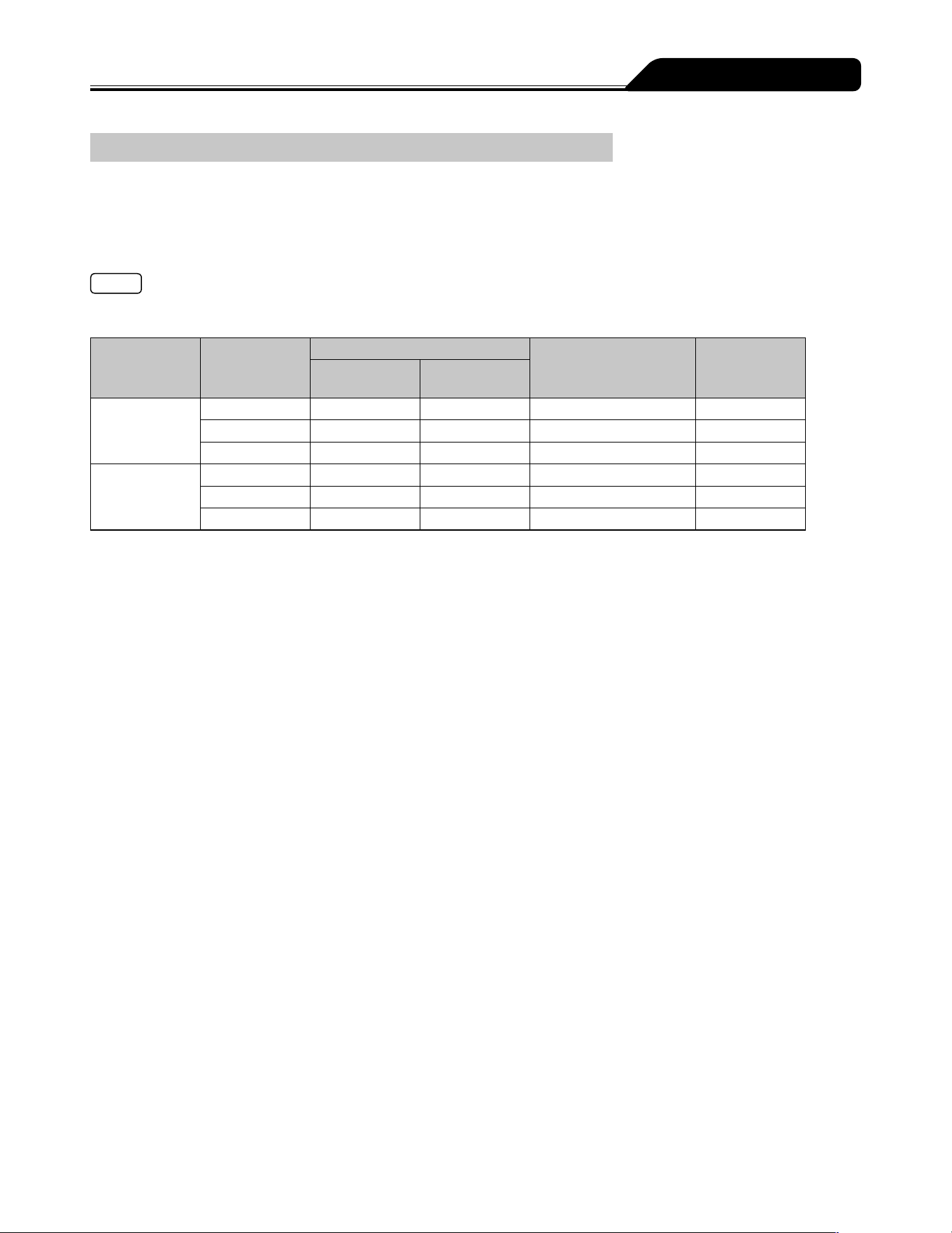
155
Device Characteristics
Occlusion Characteristics
Typical occlusion detection ability data are occlusion pressure, Occlusion alarm occurrence time, and post-occlusion removal
bolus volume. The data below is a representative example measured for flow rates of 1 mL/h and 5 mL/h, with a three-stage
occlusion pressure setting value (1, 6, 10), and a new TERUMO syringe (50 mL). The measured values may vary depending on the
test conditions.
* When the 1m extension tube (internal volume: 1.0 mL) is used.
Note
The Occlusion alarm occurrence time with solution delivery at the minimum flow rate (0.01 mL/h) will be approx. 100 times of
those at the flow rate 1 mL/h.
Flow rate
(mL/h)
Occlusion
pressure
setting value
Occlusion pressure
Time to activate an
Occlusion alarm time
(min)
Bolus volume
(mL)
(kPa) (kgf/cm
2
)
1
1 15 0.15 24.6 0.08
6 72 0.73 78.1 0.30
10 116 1.18 143.8 0.77
5
1 16 0.16 4.0 0.08
6 73 0.74 17.9 0.34
10 116 1.18 27.4 0.87

156
EMC Technical Information
Medical electrical equipment requires particular care in regards to EMC, and it is necessary to install and use the equipment in
accordance with the following EMC information.
Cautions
Ensure that the power cable used is the one provided for this product. If not, this products emissions may increase and its
immunity may decrease.
When using this product in combination with other equipment such as a network system, do not place the equipment next
to each other or stack them together. It may cause malfunctioning due to electromagnetic interference.
Portable RF communications equipment (including peripherals such as antenna cables and external antennas) should be
used no closer than 30 cm (12 inches) to any part of the TERUFUSION Syringe Pump Type SS3 OTCI, including cables
specified in this manual. Otherwise, degradation of the performance of this equipment could result.
For Medical Staff
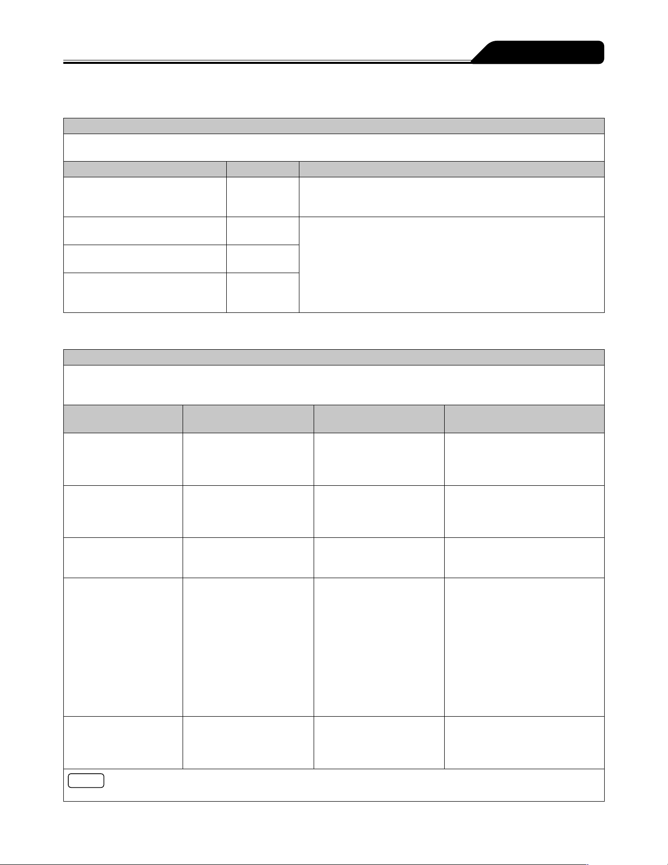
157
For Medical Staff
Table 201 Guidance and manufacturers declaration electromagnetic emissions for IEC 60601-1-2:2007 (EN 60601-1-2:2007)
for all EQUIPMENT and SYSTEMS (see 5.2.2.1 c)
Guidance and manufacturers declaration electromagnetic emissions
The TERUFUSION Syringe Pump Type SS3 OTCI is intended for use in the electromagnetic environment specified below.
The customer or the user of the TERUFUSION Syringe Pump Type SS3 OTCI should assure that it is used in such an environment.
Emissions test Compliance Electromagnetic environment-guidance
RF emissions
CISPR 11
Group 1 The TERUFUSION Syringe Pump Type SS3 OTCI uses RF energy only
for its internal function. Therefore, its RF emissions are very low and
are not likely to cause any interference in nearby electronic equipment.
RF emissions
CISPR 11
Class [B] The TERUFUSION Syringe Pump Type SS3 OTCI is suitable for use
in all establishments, including domestic establishments and those
directly connected to the public low-voltage power supply network that
supplies buildings used for domestic purposes.
Harmonic emissions
IEC 61000-3-2
Class [A]
Voltage fluctuations/
flicker emissions
IEC 61000-3-3
Complies
Table 202 Guidance and manufacturers declaration electromagnetic immunity for IEC 60601-1-2:2007 (EN 60601-1-2:2007)
for all EQUIPMENT and SYSTEMS (see 5.2.2.1 f)
Guidance and manufacturers declaration electromagnetic immunity
The TERUFUSION Syringe Pump Type SS3 OTCI is intended for use in the electromagnetic environment specified below.
The customer or the user of the TERUFUSION Syringe Pump Type SS3 OTCI should assure that it is used in such an
environment.
Immunity test IEC 60601 test level Compliance level
Electromagnetic environment-
guidance
Electrostatic
discharge (ESD)
IEC 61000-4-2
±6kV contact
±8kV air
±8kV contact
±15kV air
(*)
Floors should be wood, concrete or
ceramic tile. If floors are covered
with synthetic material, the relative
humidity should be at least 30%.
Electrical fast transient/
burst
IEC 61000-4-4
±2 kV for power supply lines
±1 kV for input/output lines
±2 kV for power
supply lines
±1 kV for input/
output lines
Mains power quality should be that
of a typical commercial or hospital
environment.
Surge
IEC 61000-4-5
±1 kV line(s) to line(s)
±2 kV line(s) to earth
±1 kV line(s) to line(s)
±2 kV line(s) to earth
Mains power quality should be that
of a typical commercial or hospital
environment.
Voltage dips, short
interruptions and voltage
variations on power supply
input lines
IEC 61000-4-11
<5% U
T
(>95% dip in U
T
) for 0.5 cycle
40% U
T
(60% dip in U
T
) for 5 cycles
70% U
T
(30% dip in U
T
) for 25 cycles
<5% U
T
(>95% dip in U
T
) for 5 s
<5% U
T
(>95% dip in U
T
) for 0.5 cycle
40% U
T
(60% dip in U
T
) for 5 cycles
70% U
T
(30% dip in U
T
) for 25 cycles
<5% U
T
(>95% dip in U
T
) for 5 s
Mains power quality should be
that of a typical commercial or
hospital environment. If the user of
the TERUFUSION Syringe Pump
Type SS3 OTCI requires continued
operation during power mains
interruptions, it is recommended that
the TERUFUSION Syringe Pump
Type SS3 OTCI be powered from
an uninterruptible power supply or a
battery.
Power frequency
(50-60 Hz) magnetic field
IEC 61000-4-8
3 A/m 3 A/m
(*)
Power frequency magnetic fields
should be at levels characteristic
of a typical location in a typical
commercial or hospital environment.
Note
U
T
is the a.c. mains voltage prior to application of the test levels.
* The TERUFUSION Syringe Pump Type SS3 OTCI complies with the more stringent levels of IEC 60601-2-24:2012 (EN 60601-2-
24:2015).
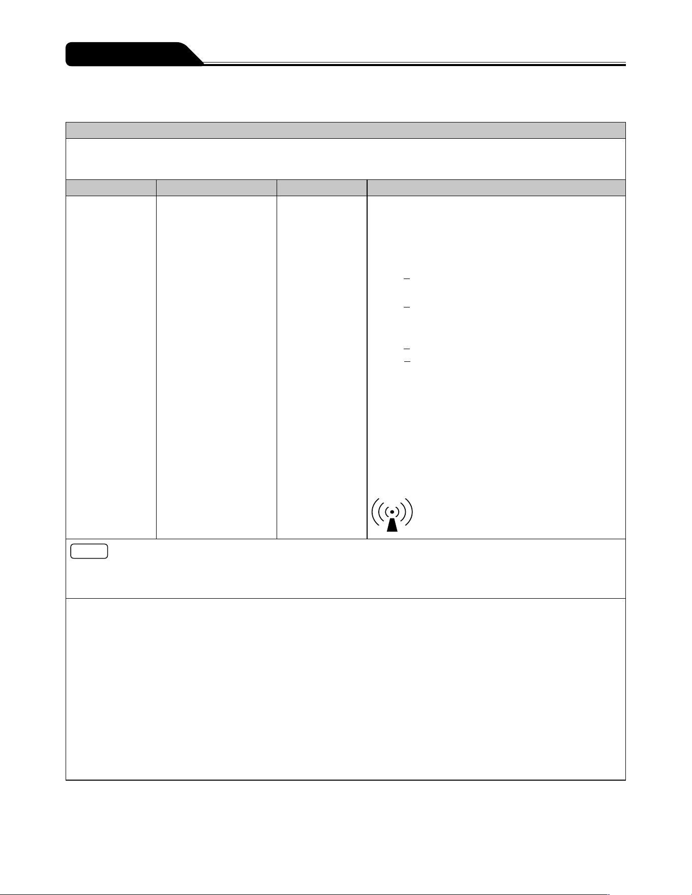
158
For Medical Staff
Table 203 Guidance and manufacturers declaration electromagnetic immunity for IEC 60601-1-2:2007 (EN 60601-1-2:2007)
for LIFE-SUPPORTING EQUIPMENT and SYSTEMS (see 5.2.2.2)
Guidance and manufacturers declaration electromagnetic immunity
The TERUFUSION Syringe Pump Type SS3 OTCI is intended for use in the electromagnetic environment specified below.
The customer or the user of the TERUFUSION Syringe Pump Type SS3 OTCI should assure that it is used in such an
environment.
Immunity test IEC 60601 test level Compliance level Electromagnetic environment-guidance
Portable and mobile RF communications equipment
should be used no closer to any part of the TERUFUSION
Syringe Pump Type SS3 OTCI, including cables, than the
recommended separation distance calculated from the
equation applicable to the frequency of the transmitter.
Conducted RF
IEC 61000-4-6
3 Vrms
150 kHz to 80 MHz
outside ISM bands
a
3 Vrms Recommended separation distance
d=1.2 √P
10 Vrms
150 kHz to 80 MHz
in ISM bands
a
10 Vrms d=1.2 √P
Radiated RF
IEC 61000-4-3
10 V/m
80 MHz to 2.5 GHz
10 V/m
d=1.2 √P 80 MHz to 800 MHz
d=2.3 √P 800 MHz to 2.5 GHz
where P is the maximum output power rating of the
transmitter in watts (W) according to the transmitter
manufacturer and d is the recommended separation
distance in metres (m).
b
Field strengths from fixed RF transmitters, as determined
by an electromagnetic site survey
c
, should be less than
the compliance level in each frequency range
d
.
Interference may occur in the vicinity of equipment
marked with the following symbol:
Notes
1. At 80 MHz and 800MHz, the higher frequency range applies.
2. These guidelines may not apply in all situations. Electromagnetic propagation is affected by absorption and reflection from
structures, objects and people.
a. The ISM (industrial, scientific and medical) bands between 150 KHz and 80 MHz are 6.765 MHz to 6.795 MHz; 13.553 MHz
to 13.567 MHz; 26.957 MHz to 27. 283 MHz; and 40.66 MHz to 40.70 MHz.
b. The compliance levels in the ISM frequency bands between 150 KHz and 80 MHz and in the frequency range 80 MHz to 2.5
GHz are intended to decrease the likelihood that mobile/portable communications equipment could cause interference if it is
inadvertently brought into patient areas. For this reason, an additional factor of 10/3 is used in calculating the recommended
separation distance for transmitters in these frequency ranges.
c. Field strengths from fixed transmitters, such as base stations for radio (cellular/cordless) telephones and land mobile radios,
amateur radio, AM and FM radio broadcast and TV broadcast cannot be predicted theoretically with accuracy. To assess
the electromagnetic environment due to fixed RF transmitters, an electromagnetic site survey should be considered. If
the measured field strength in the location in which the TERUFUSION Syringe Pump Type SS3 OTCI is used exceeds
the applicable RF compliance level above, the TERUFUSION Syringe Pump Type SS3 OTCI should be observed to verify
normal operation. If abnormal performance is observed, additional measures may be necessary, such as reorienting or
relocating the TERUFUSION Syringe Pump Type SS3 OTCI.
d. Over the frequency range 150kHz to 80 MHz, field strengths should be less than 3 V/m.
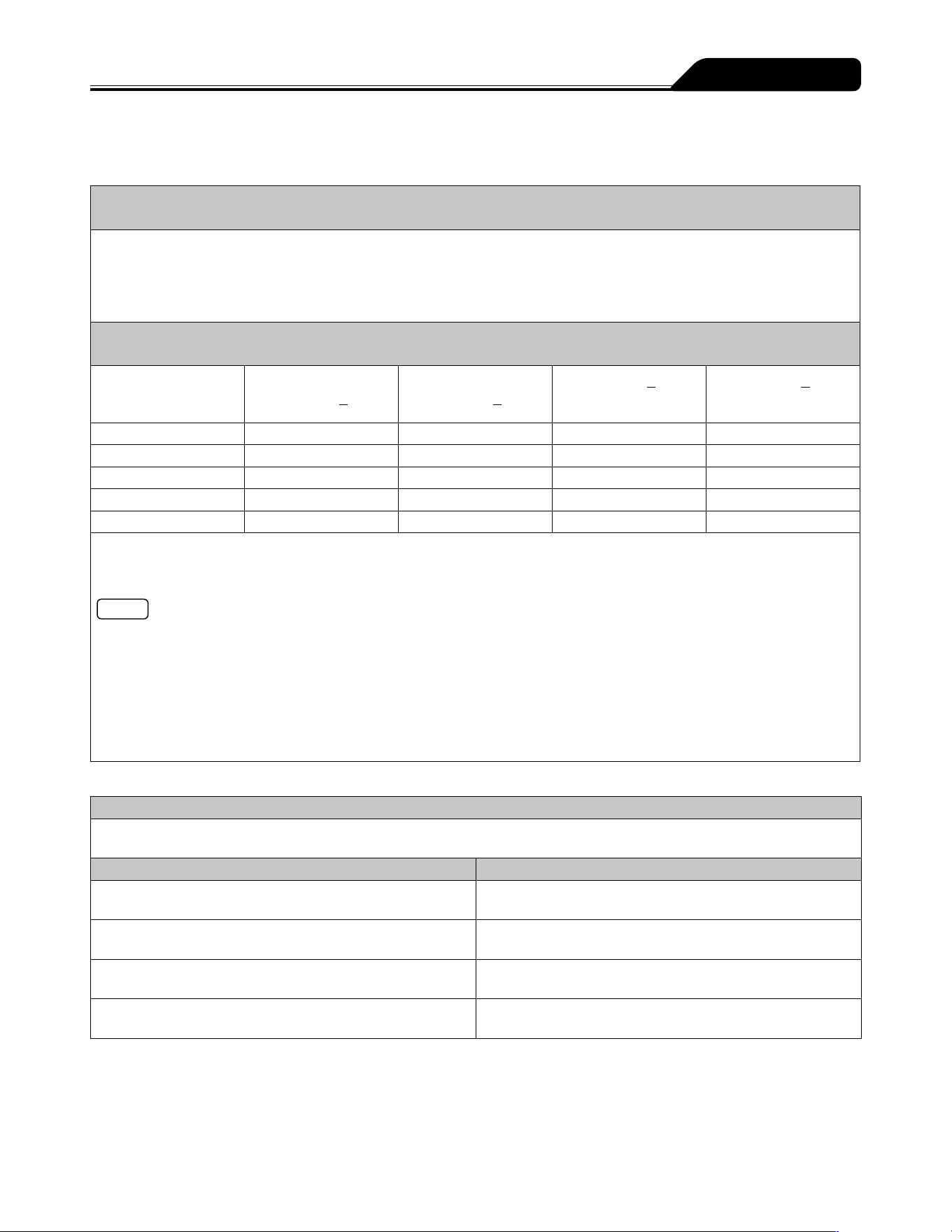
159
For Medical Staff
Table 205 Recommended separation distances between portable and mobile RF communications equipment and the
EQUIPMENT or SYSTEM for IEC 60601-1-2:2007 (EN 60601-1-2:2007)
for LIFESUPPORTING EQUIPMENT and SYSTEMS (see 5.2.2.2)
Recommended separation distances between portable and mobile RF communications
equipment and the TERUFUSION Syringe Pump Type SS3 OTCI
The TERUFUSION Syringe Pump Type SS3 OTCI is intended for use in an electromagnetic environment in which radiated RF
disturbances are controlled. The customer or the user of the TERUFUSION Syringe Pump Type SS3 OTCI can help prevent
electromagnetic interference by maintaining a minimum distance between portable and mobile RF communications equipment
(transmitters) and the TERUFUSION Syringe Pump Type SS3 OTCI as recommended below, according to the maximum output
power of the communications equipment.
Separation distance according to frequency of transmitter
m
Rated maximum output
power of transmitter
W
150 kHz to 80 MHz
outside ISM bands
d=1.2 √P
150 kHz to 80 MHz in
ISM bands
d=1.2 √P
80 MHz to 800 MHz
d=1.2 √P
800 MHz to 2.5 GHz
d=2.3 √P
0.01 0.12 0.12 0.12 0.23
0.1 0.38 0.38 0.38 0.73
1 1.2 1.2 1.2 2.3
10 3.8 3.8 3.8 7.3
100 12 12 12 23
For transmitters rated at a maximum output power not listed above, the recommended separation distance d in metres (m) can
be determined using the equation applicable to the frequency of the transmitter, where P is the maximum output power rating of
the transmitter in watts (W) according to the transmitter manufacturer.
Notes
1. At 80 MHz and 800 MHz, the separation distance for the higher frequency range applies.
2. The ISM (industrial, scientific and medical) bands between 150 kHz and 80 MHz are 6.765 MHz to 6.795 MHz; 13.553 MHz
to 13.567 MHz; 26.957 MHz to 27.283 MHz; and 40.66 MHz to 40.70 MHz.
3. An additional factor of 10/3 is used in calculating the recommended separation distance for transmitters in the ISM
frequency bands between 150 kHz and 80 MHz and in the frequency range 80 MHz to 2.5 GHz to decrease the likelihood
that mobile/portable communications equipment could cause interference if it is inadvertently brought into patient areas.
4. These guidelines may not apply in all situations. Electromagnetic propagation is affected by absorption and reflection from
structures, objects and people.
Table a) Manufacturers declaration electromagnetic emissions for IEC 60601-1-2:2014 (EN 60601-1-2:2015)
Manufacturers declaration - electromagnetic emissions
The TERUFUSION Syringe Pump Type SS3 OTCI is intended for use in the electromagnetic environment specified below. The
customer or the user of the TERUFUSION Syringe Pump Type SS3 OTCI should assure that it is used in such an environment.
Emissions test Emissions class and group
RF emissions
CISPR 11
Group 1
RF emissions
CISPR 11
Class [A]*
Harmonic emissions
IEC 61000-3-2
Class [A]
Voltage fluctuations / flicker emissions
IEC 61000-3-3
Complies
* The EMISSIONS characteristics of this equipment make it suitable for use in industrial areas and hospitals (CISPR 11 class A). If
it is used in a residential environment (for which CISPR 11 class B is normally required) this equipment might not offer adequate
protection to radiofrequency communication services. The user might need to take mitigation measures, such as relocating or
re-orienting the equipment.
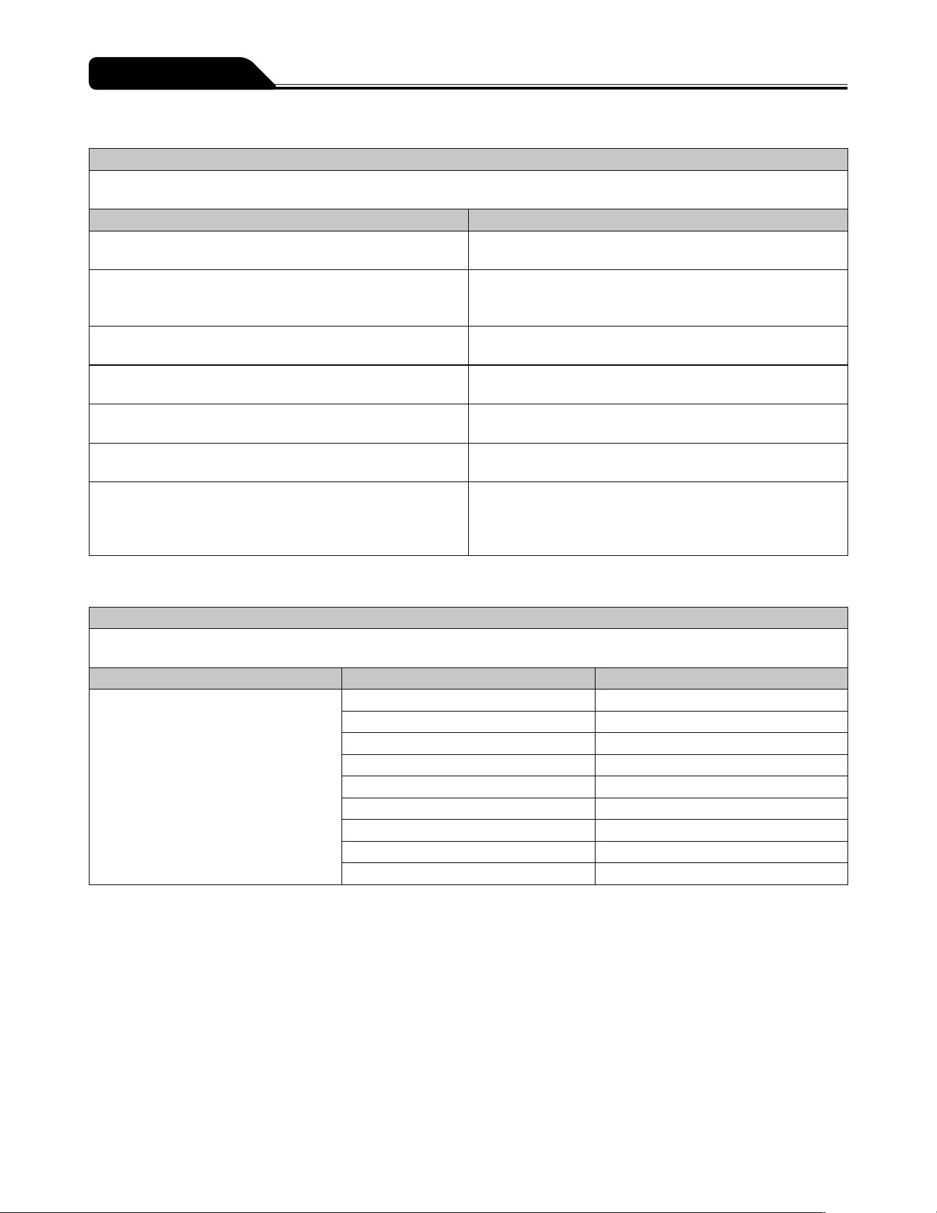
160
For Medical Staff
Table b) Manufacturers declaration electromagnetic immunity for IEC 60601-1-2:2014 (EN 60601-1-2:2015)
Manufacturers declaration - electromagnetic immunity
The TERUFUSION Syringe Pump Type SS3 OTCI is intended for use in the electromagnetic environment specified below. The
customer or the user of the TERUFUSION Syringe Pump Type SS3 OTCI should assure that it is used in such an environment.
Immunity test Immunity test level
Electrostatic discharge (ESD)
IEC 61000-4-2
±8 kV contact
±15 kV air
Radiated RF
IEC 61000-4-3
3 V/m 80 MHz to 2.7 GHz
See Table c) for immunity test level to RF Wireless
communication equipment
Electrical fast transient / burst
IEC 61000-4-4
±2 kV for power supply lines
±1 kV for input / output lines
Surge
IEC 61000-4-5
±1 kV line(s) to line(s)
±2 kV line(s) to earth
Conducted RF
IEC 61000-4-6
3 Vrms 150 kHz to 80 MHz outside ISM bands
6 Vrms 150 kHz to 80 MHz in ISM bands
Power frequency (50-60 Hz) magnetic field
IEC 61000-4-8
30 A/m
Voltage dips, short interruptions and voltage variations on
power supply input lines
IEC 61000-4-11
0% U
T
for 0.5 cycle
0% U
T
for 1 cycle
70% U
T
for 25/30 cycles
0% U
T
for 250/300 cycles
Table c) Immunity test level to proximity fields from RF communications equipment for IEC 60601-1-2:2014 (EN 60601-1-2:2015)
Immunity test level to proximity fields from RF communications equipment
The TERUFUSION Syringe Pump Type SS3 OTCI is intended for use in the electromagnetic environment specified below. The
customer or the user of the TERUFUSION Syringe Pump Type SS3 OTCI should assure that it is used in such an environment.
Emissions test Test frequency (MHz) Immunity test level (V/m)
Proximity fields from RF communications
equipment
IEC 61000-4-3
385 27
450 28
710, 745, 780 9
810, 870, 930 28
1720, 1845, 1970 28
2100 10
2450 28
2600, 3500 10
5240, 5500, 5785 9
161
This section describes the symbols (icons) used with the TERUFUSION Syringe Pump Type SS3 OTCI.
Description of Symbols
Symbol
Description of
Symbols
Symbol
Description of
Symbols
Symbol
Description of
Symbols
CE means compliance
with the European
Directive 2011/65/EU on
the restriction of the use
of certain hazardous
substances in electrical
and electronic
equipment as well
as with the essential
requirements and other
relevant provisions of
Directive 2014/53/EU
(self-declaration).
CE0197 means
compliance with
the Medical Device
Directive, 93/42/EEC.
Purge Atmospheric pressure
limitation
Start Stacking limit by
number
Stop Defibrillation-proof type
CF applied part
IP24
IEC 60529 Degrees of
protection provided by
enclosures (IP code)
Indicates recyclable
corrugated paper
packing material
(Japan)
EC REP
Authorized
Representative in the
European Community
Indicates the operation
to pull the clamp
forward
SN
Serial number
#
Contents Indicates PE
(polyethylene) plastic
bag (Japan)
REF
Catalogue number Consult instructions for
use
Recyclable (Lithium-ion
battery) Brazil
Date of manufacture Follow instructions for
use
Contains RoHS 6
Restricted Substances
(Lithium-ion battery)
China
Manufacturer This way up Recyclable (Lithium-ion
battery, Nickel-metal-
hydride battery) Taiwan
Alternating current Fragile, handle with
care
TISI mark (Lithium-ion
battery) Thailand
DC power supply Keep dry Recyclable (Lithium-ion
battery) Japan
off (for a part of
equipment)
Keep away from
sunlight
Separate collection
of accumulators and
batteries
on (for a part of
equipment)
Temperature limit Separate collection of
electrical and electronic
equipment, European
Community
Return Humidity limitation Non-ionizing
electromagnetic
radiation
Mute
(Audio paused)
Note
See pages 7 to 16 for symbols on the operation panel and LCD.
Symbols

162
Simplified EU Declaration of Conformity
(Radio Equipment Directive, 2014/53/EU)
Simplified EU Declaration of Conformity (Radio Equipment Directive, 2014/53/
EU)
Hereby, TERUMO CORPORATION declares that the radio equipment type
TERUFUSION Syringe Pump Type SS3 OTCI is in compliance with
Directive 2014/53/EU.
The full text of the EU declaration of conformity is available at the following
internet address:
http://www.terumo-europe.com
Other Information

163
Memo

is a trademark of TERUMO CORPORATION.
IrDA is a trademark or registered trademark of Infrared Data Association. ® : Registered trademark ©TERUMO CORPORATION 2019-08-01 19G01
TE_SS830P_E_501_002
TERUMO CORPORATION
44-1, 2-CHOME, HATAGAYA, SHIBUYA-KU, TOKYO 151-0072, JAPAN
TERUMO EUROPE N.V.
INTERLEUVENLAAN 40, 3001 LEUVEN, BELGIUM
EC REP
MADE IN JAPAN
FOR INFORMATION ABOUT TERUMO PRODUCTS
If this product should fail to perform as intended, immediately stop using the product and contact the nearest branch or sales
office of TERUMO.
As of August, 2019
TERUMO EUROPE N.V.
Tel.: +32 16 38 12 11
Fax: +32 16 40 02 49
TERUMO EUROPE N.V.
BENELUX SALES DIVISION
(Belgium)
Tel.: +32 16 39 25 80
Fax: +32 16 39 25 99
(Netherlands)
Tel.: +0800 0220396
Fax: +0800 0220414
TERUMO FRANCE S.A.S.
Tel.: +33 1 30 96 13 00
Fax: +33 1 30 43 60 85
TERUMO DEUTSCHLAND GmbH
Tel.: +49 6196 80 230
Fax: +49 6196 80 23 200
TERUMO DEUTSCHLAND GmbH
ZWEIGNIEDERLASSUNG
SPREITENBACH
Tel.: +41 56 419 10 10
Fax: +41 56 419 10 11
TERUMO EUROPE ESPANA SL
Tel.: +34 902 10 12 98
Fax: +34 902 10 13 58
TERUMO ITALIA SRL
Tel.: +39 06 94 80 28 00
Fax: +39 06 60 51 32 33
TERUMO SWEDEN AB
Tel.: +46 3174 85 880
Fax: +46 3174 85 890
TERUMO DENMARK
FILIAL OF TERUMO SWEDEN AB
Tel.: +45 7020 93 80
Fax: +45 7020 94 80
TERUMO UK Ltd.
Tel.: +44 1276 480440
Fax: +44 1276 480465
TERUMO RUSSIA LLC
Tel.: +7 495 988 4740
Fax: +7 495 988 4739
TERUMO MEDICAL CORPORATION
265 Davidson Avenue, Suite 320,
Somerset, NJ 08873 USA
Tel.: +1 732 302 4900
Fax: +1 732 302 3083
Toll free :+1 800 283 7866
TERUMO LATIN AMERICA
CORPORATION
Doral Corporate Center I
8750 NW 36th street, Suite 600
Miami, FL 33178, U.S.A.
Tel.: +1 305 477 4822
Fax: +1 305 477 4872
TERUMO MEDICAL
de MEXICO, S.A. de C.V.
Av. Insurgentes Sur # 1647
piso 11 Colonia San Jose Insurgentes
C.P. 03900 Delegacion Benito Juarez
Mexico D.F.
Tel.: +52 55 10 85 07 70
Fax: +52 55 10 85 07 71
TERUMO MEDICAL
do BRASIL Ltda.
Praça General Gentil Falcão,
108 cj 91 e 92
- São Paulo - SP
- Brasil - CEP: 04571 - 150
Tel.: +55 11 3594 3800
Fax: +55 11 3594 3801
TERUMO CHILE Ltda.
Carmencita 25, Oficina 22 piso 2, Edificio
Central Park, Las Condes, Santiago
755-0000, Chile
Tel.: +56 2 2480 9600
Fax: +56 2 2480 9608
TERUMO SINGAPORE Pte. Ltd.
300 Beach Road,
#33-06 The Concourse
Singapore 199555
Tel.: +65 6 291 3603
Fax: +65 6 291 2696
TERUMO (THAILAND) Co., Ltd.
#1206, 12th Floor 54 B.B. Building Asoke
Road (Sukhumvit 21), Kwaeng
Klongtoeynua,
Khet Wattana, Bangkok 10110, Thailand
Tel.: +66 2 260 7020
Fax: +66 2 260 7019
TERUMO VIETNAM MEDICAL
EQUIPMENT Co., Ltd.
14th Floor, Geleximco Building,
36 Hoang Cau Street, O Cho Dua Ward,
Dong Da District, Hanoi, Vietnam
Tel.: +84 4 3936 1643
Fax: +84 4 3936 1641
TERUMO VIETNAM MEDICAL
EQUIPMENT Co.,Ltd.
HO CHI MINH CITY BRANCH
Room 505, 5th floor,
HOANG ANH SAFOMEC Office Building,
7/1 Thanh Thai Str., Ward14, District 10,
Ho Chi Minh City, Vietnam
Tel.: +84 8 3866 9263
Fax: +84 8 3866 9261
P.T. TERUMO INDONESIA
Wisma KEIAI 5th Floor JL.Jend.Sudirman
KAV.3
Jakarta 10220, Indonesia
Tel.: +62 21 572 4071
Fax: +62 21 572 4072
TERUMO MALAYSIA Sdn. Bhd.
Suite C405, 4th Floor, Centre Tower
Wisma Consplant 1
No. 2, Jalan SS 16/4 47500 Subang Jaya
Selangor Darul Ehsan, Malaysia
Tel.: +60 3 5880 8898
Fax: +60 3 5880 8891
TERUMO MARKETING PHILIPPINES,
INC.
Unit 3203 A & B, West Tower, Philippine
Stock Exchange Centre, Exchange Road,
Ortigas Centre, Pasig City, Philippines
Tel.: +63 02 632 1674
Fax: +63 02 632 7966
TERUMO TAIWAN MEDICAL Co., Ltd.
7C, No. 170 Tun-Hwa North Road
Taipei, Taiwan, R.O.C.
Tel.: +886 2 2545 1250
Fax: +886 2 2545 1251
TERUMO CHINA (HONG KONG) Ltd.
Room 607-608, 6/F, Harcourt House,
39 Gloucester Road, Wanchai,
Hong Kong
Tel.: +852 2866 0811
Fax: +852 2529 0451
TERUMO MEDICAL (SHANGHAI) Co.,
Ltd.
Rm.901, Zhongshan Expo Plaza,
666 Huaihai Road West,
Changning, Shanghai 200052, China
Tel.: +86 21 6237 1155
Fax: +86 21 6237 1150
TERUMO KOREA CORPORATION
23rd Fl., GT Tower, 411, Seocho-daero,
Seocho-gu, Seoul, 06615 Korea
Tel.: +82 2 565 9225
Fax: +82 2 565 9224
TERUMO AUSTRALIA PTY LIMITED
Macquarie Park NSW 2113, Australia
Tel.: +61 2 9878 5122
TERUMO CORPORATION CHENNAI
BRANCH
Alexander Square, 2nd Floor,
No.34 & 35 Sardar Patel Road, Guindy,
Chennai 600 032, India
Tel.: +91 44 2230 0634
Fax: +91 44 2230 0622
Terumo Middle East FZE
Building 8WB - Office#317
Dubai Airport Free Zone (DAFZ)
P.O. Box 54614 Dubai
United Arab Emirates
Tel.: +971 4 292 0200
Fax: +971 4 292 0222