FSS-31
FSS-14 FSS-43
FSS-95
REFER TO COMPLETE INDEX OF
INFORMATION ON PAGE 2.
EXTREMELY HIGH TEMPERATURES ARE
PRESENT, DURING OPERATION. MAINTAIN
CLEARANCES FROM COMBUSTIBLES AS
STATED IN MANUAL.
ISSUE DATE 07-2015 REV. DATE ------------ REV. LEVEL: - ECO 1-7090 OIPM P/N 8419 PG 1 OF12
TPI Corporation
P.O. Box 4973
Johnson City, TN 37602
www.tpicorp.com
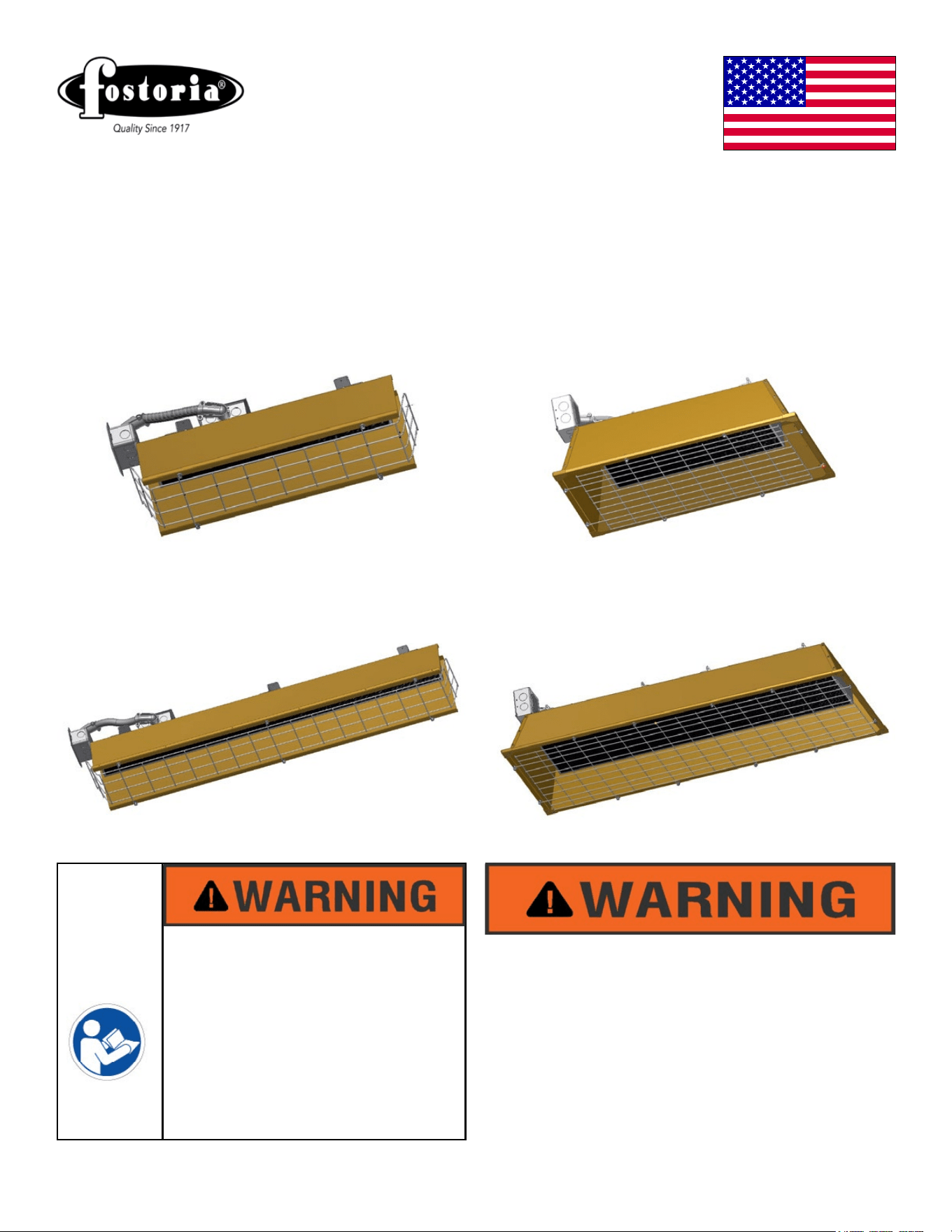
FSS-Series
Heavy-Duty Flat panel Emitter
Electric Overhead Infrared Heaters
IMPORTANT SAFETY INFORMATION
INSIDE
• Serious injury or death possible
• Read, understand and follow all safety
information and instructions in this manual
before using or servicing this product.
• Retain these instructions for future use.
ISSUE DATE 07-2015 REV. DATE ------------ REV. LEVEL: - ECO 1-7090 OIPM P/N 8419 PG 2 OF12
IMPORTANT INSTRUCTIONS
1. Read all instructions before installing or using the heater.
2. This heater is hot when in use. To avoid burns, do not let bare skin touch hot surfaces. Keep away
from combustible materials at minimum, the following required distances. DO NOT install closer
than 36 inches to a vertical surface or 24 inches to a ceiling. Heaters MUST BE SEPARATED by
more than 36 inches and 72 inches from any combustible surface in direct radiation path (87 inches
for FSS-19 Series).
3. Extreme caution is necessary when any heater is used by or near children or invalids and whenever
the heater is left operating and unattended.
4. Do not operate any heater after it malfunctions. Disconnect power at service panel and have heater
inspected by a reputable electrician before reusing.
5. Do not use outdoors.
6. To disconnect heater, turn controls to off, and turn off power to heater circuit at the main disconnect
panel (or operate internal disconnect switch if provided).
7. Do not insert or allow foreign objects to enter any ventilation or exhaust opening as this may cause
an electric shock or re, or damage to the heater.
8. To prevent a possible re, do not block air intakes or exhaust in any manner.
9. A heater has hot and arcing or sparking parts inside. Do not use it in areas where gasoline, paint or
ammable vapors or liquids are used or stored.
10. Use this heater only as described in this manual. Any other use not recommended by the
manufacturer may cause re, electric shock, or injury to persons.
11. SAVE THESE INSTRUCTIONS.
General Description & Use Page 4
Specications Page 4, 5, 6
Installation Planning Pages 7, 8
Installation - Hanging Heaters Pages 8, 9
Installation - Wiring Pages 10, 12
Operation Page 11
Maintenance Page 11
INDEX
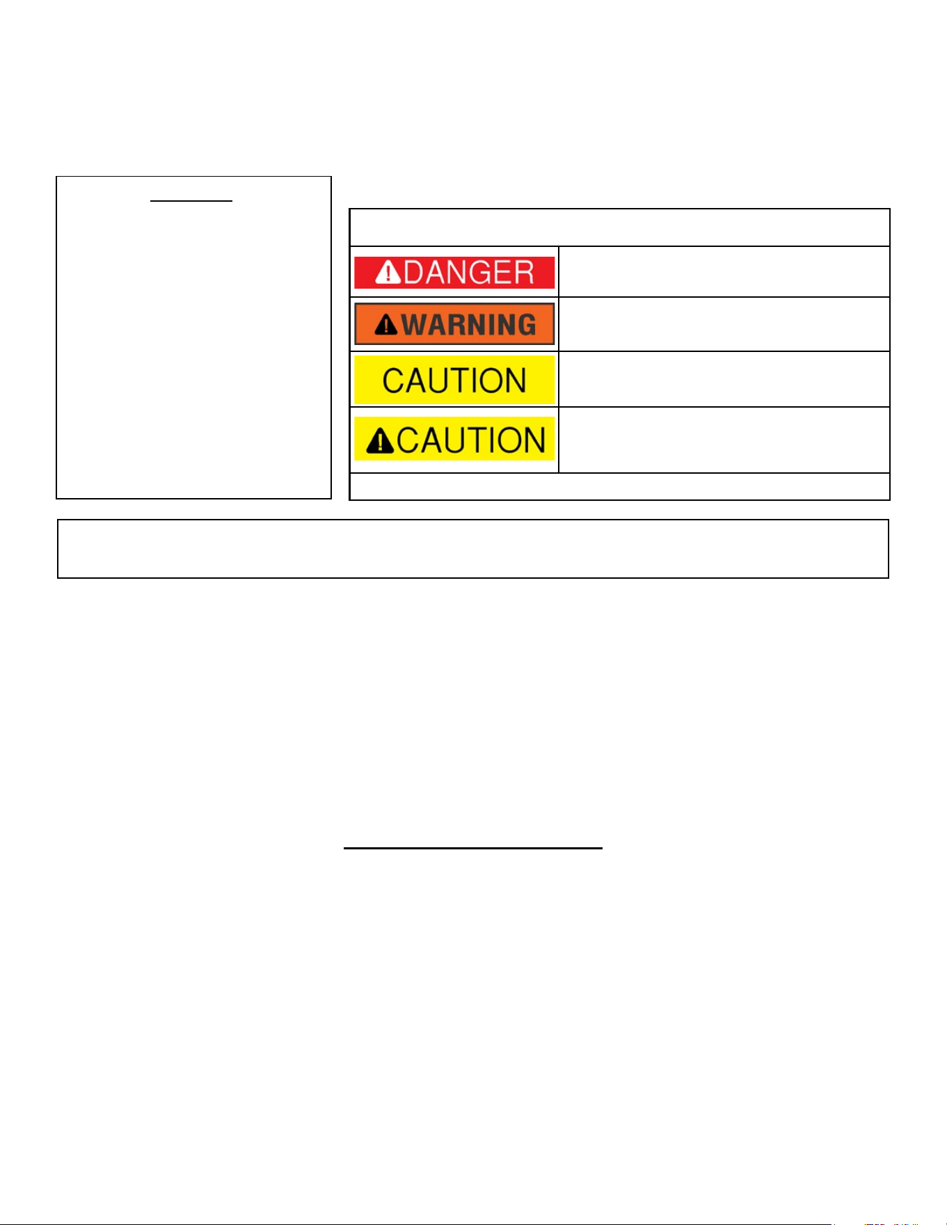
ATTENTION:
The table to the right provides
definitions of the signal words that
can be found throughout this
manual. These signal words are
used to express the severity of
the hazard at hand. The signal
words are generally used in
conjunction with safety symbols
that correspond to the text for that
particular hazard. As you read
this manual, refer back to this
table when you are unsure of the
signal word definition.
ISSUE DATE 07-2015 REV. DATE ------------ REV. LEVEL: - ECO 1-7090 OIPM P/N 8419 PG 3 OF12
SIGNAL WORD DEFINITIONS
DANGER indicates an imminently hazardous
situation which, if not avoided, will result in
death or serious injury
WARNING indicates an imminently hazardous
situation which, if not avoided, could result
in death or serious injury
CAUTION indicates an imminently hazardous
situation which, if not avoided, may result in
minor or moderate injury
CAUTION used without the safety alert symbol
indicates a potentially hazardous situation
which, if not avoided, may result in property
damage.
As dened in ANSI Z535-4-2002
Thank you very much for selecting Fostoria’s overhead electric infrared heating equipment for your
comfort heating needs. These products were engineered with the most reliable components and
materials available and are equipped with features to assure ease of installation and maintenance.
The warmth you will now enjoy when using this heating equipment is created by a heat source; a at
panel emitter; that emits infrared energy in the form of heat, like the sun. This is an economical way
to heat because it heats people and objects, not the air, so you don’t need to heat a large area to feel
warm.
CHECKING YOUR SHIPMENT
• Upon receipt of your shipment, check all cartons for visible damage.
• Claims for damaged material or shortages that were not evident upon receipt of shipment must
be reported to carrier and TPI Corporation’s customer service (800-251-0382) immediately.
• Any accessory items ordered for the heater will be shipped in separate cartons.
THANK YOU!!
ISSUE DATE 07-2015 REV. DATE ------------ REV. LEVEL: - ECO 1-7090 OIPM P/N 8419 PG 4 OF12
The Fostoria FSS-Series heaters provide
safe, efficient electric infrared heat for total
area heating or spot heating applications for
warehouses, steel mills, machine shops and
many other industrial applications They are
ideal for use in high vibration environments.
Using the “L” brackets on the top of the
housing these overhead heaters can be hung
by chain or rigidly mounted They operate
cleanly, emitting no fumes or odors.
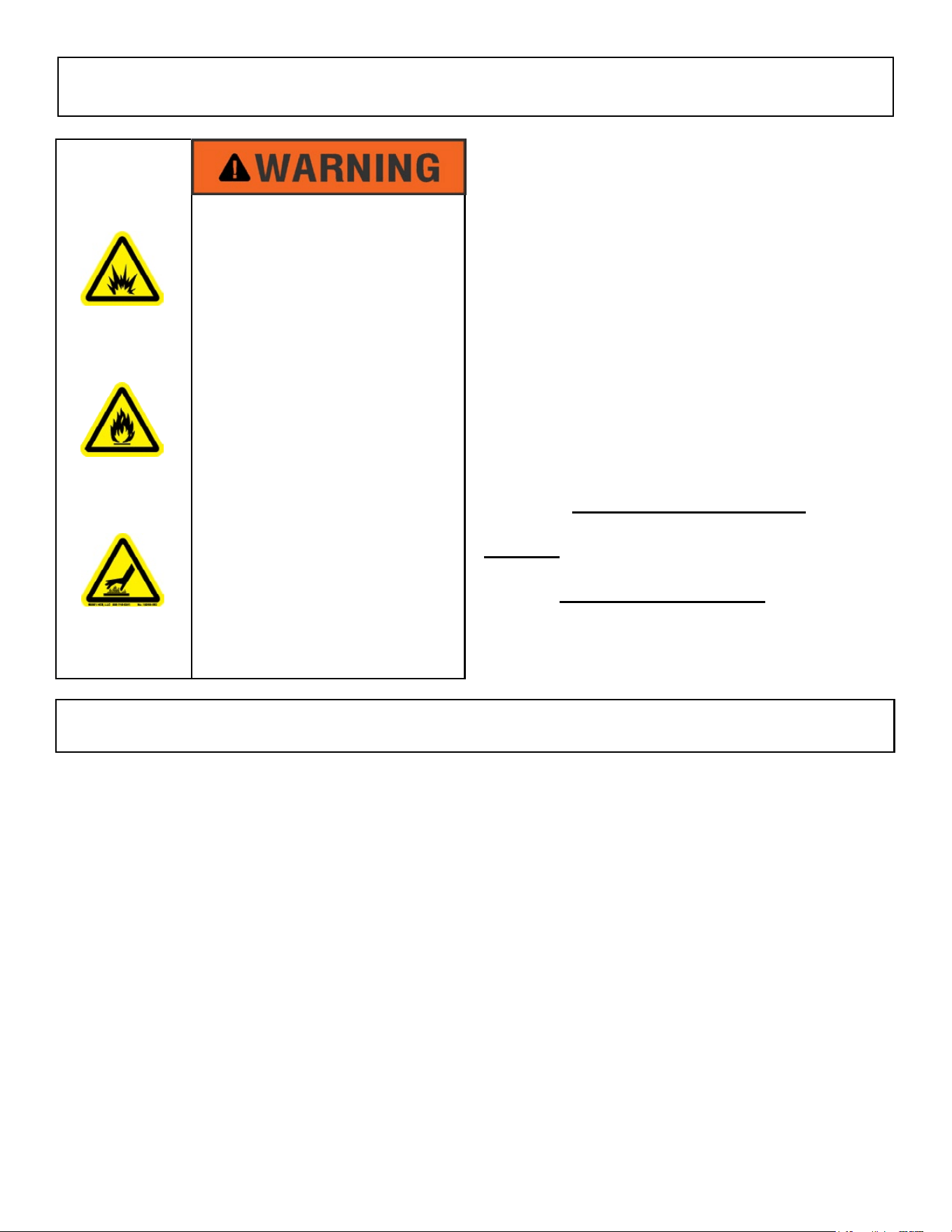
Applications where combustible materials and/or
personnel will be located near these heaters must
adhere to the minimum clearance information
below
REQUIRED CLEARANCES
DO NOT install closer than 36 inches to
a vertical surface or 24 inches to a ceiling.
Heaters MUST BE SEPARATED by more than
36 inches and 72 inches from any combustible
surface in direct radiation path (87 inches for
FSS-95 Series).
EXPLOSION HAZARD
FIRE HAZARD
BURN HAZARD
• Serious injury or death may
occur
• Not for residential use.
• Do not use outdoors.
• Use for comfort heating only
• Do not use locations
containing hazardous or
explosive atmospheres
• ETL listed for suspended, high-bay indoor applications (see table on next page)
• High-watt-density radiant heat with 60
degree heat pattern.
• Gold-anodized aluminum housing for good reectivity and corrosion resistance
• “L-brackets included for chain suspension or rigid-mounting.
• Designed for direct-wire, single or three-phase congurations (see table next page).
SPECIFICATIONS
GENERAL DESCRIPTION & USE
ISSUE DATE 07-2015 REV. DATE ------------ REV. LEVEL: - ECO 1-7090 OIPM P/N 8419 PG 5 OF12
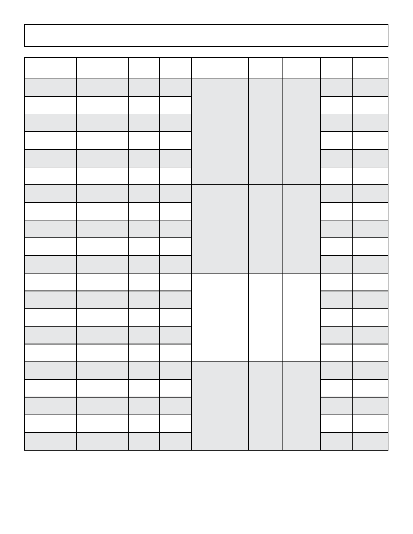
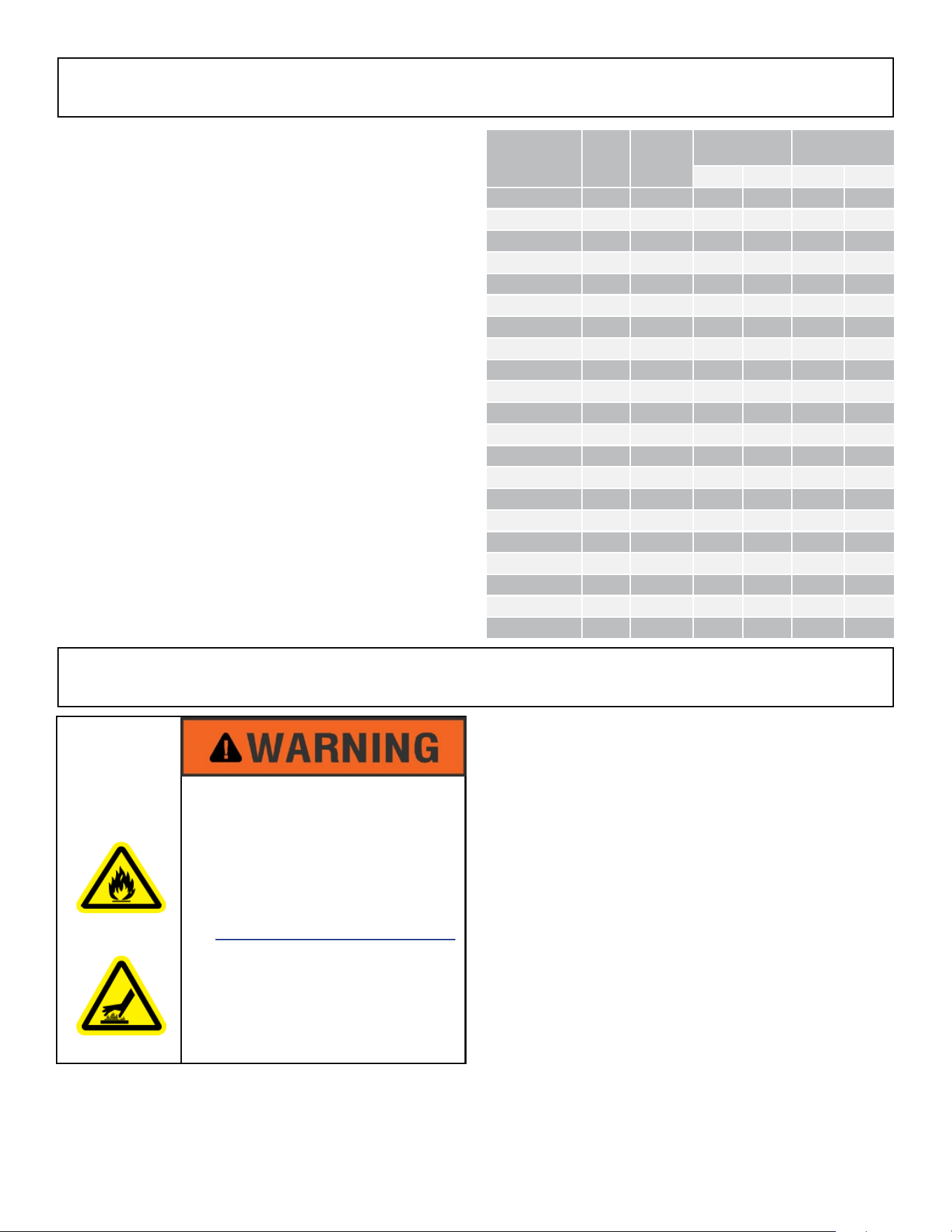
Heater
Models
Voltage
And Phase
Amps
1ph.
Amps
3ph.
Number
Of Elements
Watts Btu’s/Hr.
ETL
listed
cETLus
certied
FSS-1412-1 120; 1ph 12.1 N/A
1 1450 4947
Yes Yes
FSS-1420-1 208; 1ph 6.97 N/A Yes Yes
FSS-1424-1 240; 1ph 6.04 N/A Yes Yes
FSS-1427-1 277; 1ph 5.23 N/A Yes Yes
FSS-1448-1 480; 1ph 3.02 N/A Yes Yes
FSS-1457-1 600; 1ph 2.52 N/A Yes Yes
FSS-3120-1 120; 1ph 15.14 N/A
1 3150 10,748
Yes Yes
FSS-3124-1 240; 1ph 13.13 N/A Yes Yes
FSS-3127-1 277; 1ph 11.37 N/A Yes Yes
FSS-3148-1 480; 1ph 6.56 N/A Yes Yes
FSS-3157-1 600; 1ph 5.48 N/A Yes Yes
FSS-4320-3 208; 1 or 3ph 20.67 11.94
1 4300 14,672
Yes Yes
FSS-4324-3 240; 1 or 3ph 17.91 10.36 Yes Yes
FSS-4327-1 277; 1ph 15.52 N/A Yes Yes
FSS-4348-3 480; 1 or 3ph 8.96 5.18 Yes Yes
FSS-4357-3 600; 1 or 3ph 7.48 4.32 Yes Yes
FSS-9520-3 208; 3ph N/A 26.39
1 9500 32,414
Yes Yes
FSS-9524-3 240; 3ph N/A 22.89 Yes Yes
FSS-9527-1 277; 1ph 34.3 N/A Yes Yes
FSS-9548-3 480; 3ph N/A 11.44 Yes Yes
FSS-9557-3 600; 3ph N/A 9.54 Yes Yes
SPECIFICATIONS (con’t.)
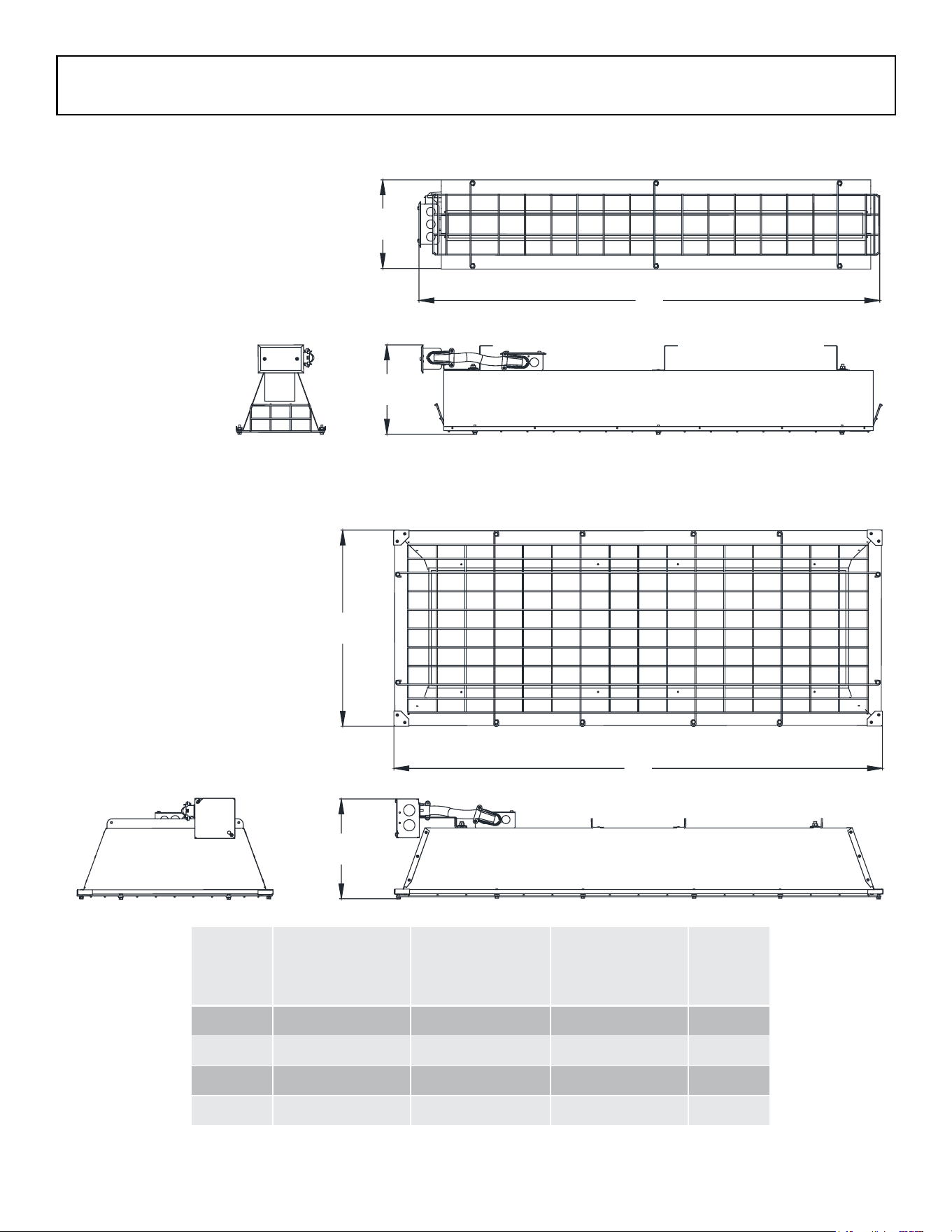
B
FSS-43, FSS-95
A
C
B
C
A
FSS-14, FSS-31
ISSUE DATE 07-2015 REV. DATE ------------ REV. LEVEL: - ECO 1-7090 OIPM P/N 8419 PG 6 OF12
Model
Series
Dimension A
(inches)
Dimension B
(inches)
Dimension C
(inches)
Weight
(lbs.)
FSS-14 8-1/2 9 26 7
FSS-31 8-1/2 9 46 13
FSS-43 9-3/4 20 29 18
FSS-95 7-3/4 20 49 31
SPECIFICATIONS (con’t.)
Fostoria’s at panel emitter heaters are equipped with heating elements that are manufactured using
materials with exceptional mechanical and thermal performance and are built with precise process
control to provide rugged and reliable infrared performance in challenging environments. It is our
understanding that these precision characteristics can change with time, specically in environments
with high humidity or where mechanical damage can occur, causing the internal electrical insulation to
weaken.
Installer Qualications
The installation and wiring of Fostoria MR heaters
must be performed by a licensed electrician.
Installer Responsibility
The National Electric Code (NEC) and local
codes and ordinances together with specications
provided by Fostoria comprise the information
needed for proper installation.
The installer must furnish all materials that
have not been purchased from Fostoria or its
representatives. It is the installer’s responsibility
that the materials and methods of installation
result in a job that is workmanlike and compliant
with all applicable codes.
Preparations For Hanging Heaters
• Hardware to suspend these heaters from overhead supports (chain, “S”-hooks etc.) is not included
with the product. Make certain that the hardware to be used is capable of supporting at least twice
the total weight of the heater’s in question. Refer to the specications section of this manual for
product weights.
• Identify and use installation locations that are strictly compliant with the clearance-to-combustibles
requirements in the installation section of this manual.
• Mounting height is an important consideration to assure satisfaction with the heating performance
of infrared heaters. Fostoria has many years of practical experience in the successful applica-
tion of infrared technology. For that reason, recommended mounting heights have been included
in the installation section of this manual. Please refer to this data and select installation points
where these recommendations can be followed.
`
FIRE HAZARD
• Serious injury or death may
occur.
• Heater circuit load calculations
and circuit design must be
done by a licensed electrician
or engineer.
INSTALLATION PLANNING
ISSUE DATE 07-2015 REV. DATE ------------ REV. LEVEL: - ECO 1-7090 OIPM P/N 8419 PG 7 OF12
Supply Wire Size Recommendations
The table at the right is provided to assist the
licensed electrician in sizing the electric supply
wires required to deliver power to each individual
heater. All branch circuit supply wiring must be
copper, rated 90o C minimum and comply with all
local codes and the NEC.
All recommended wire sizes assume a 50ft.
maximum wire length.
REQUIRED CLEARANCES
DO NOT install heaters closer than 36 inches to a
vertical surface or 24 inches to a ceiling. Heaters
MUST BE SEPARATED by more than 36 inches
and 72 inches from any combustible surface in
direct radiation path (87 inches for FSS-95
Series).
HEATER HANGING ALTERNATIVES
One method of hanging the heaters (shown
below) is with hardware chain and “S” hooks. The
chain and “S” hooks must be either 14 or 16 gauge
for all models. The heaters also can be mounted
“xed” with angle iron, metal rods or metal straps.
Whatever means is used to mount the heaters,
the terminal box must be EVEN WITH or LOWER
THAN the horizontal plane of the heater housing.
ISSUE DATE 07-2015 REV. DATE ------------ REV. LEVEL: - ECO 1-7090 OIPM P/N 8419 PG 8 OF12
FIRE HAZARD
BURN HAZARD
• Install heaters to comply with
REQUIRED CLEARANCES
listed above at right.
• Do not mount heaters
vertically.
INSTALLATION - HANGING HEATERS
INSTALLATION PLANNING (CON’T.)
Heater Model kW Volts
Amps
Recommended
AWG Wire Size
3ph 1ph 3ph 1ph
FSS-1412-1 1.45 120 N/A 12.08 N/A 12
FSS-1420-1 1.45 208 N/A 6.97 N/A 12
FSS-1424-1 1.45 240 N/A 6.04 N/A 12
FSS-1427-1 1.45 277 N/A 5.23 N/A 12
FSS-1448-1 1.45 480 N/A 3.02 N/A 12
FSS-1457-1 1.45 600 N/A 2.52 N/A 12
FSS-3120-1 3.15 208 N/A 15.14 N/A 12
FSS-3124-1 3.15 240 N/A 13.13 N/A 12
FSS-3127-1 3.15 277 N/A 11.37 N/A 12
FSS-3148-1 3.15 480 N/A 6.56 N/A 12
FSS-3157-1 3.15 600 N/A 5.48 N/A 12
FSS-4320-3 4.3 208 11.9 20.67 12 10
FSS-4324-3 4.3 240 10.4 17.9 12 10
FSS-4327-1 4.3 277/480 5.2 15.5 12 12
FSS-4348-3 4.3 480 5.2 9.0 12 12
FSS-4357-3 4.3 600 4.3 7.5 12 12
FSS-9520-3 9.5 208 26.4 45.7 8 8
FSS-9524-3 9.5 240 22.9 39.6 10 8
FSS-9527-1 9.5 277/480 11.4 34.3 12 8
FSS-9548-3 9.5 480 11.4 19.8 12 10
FSS-9557-3 9.5 600 9.5 16.5 12 10
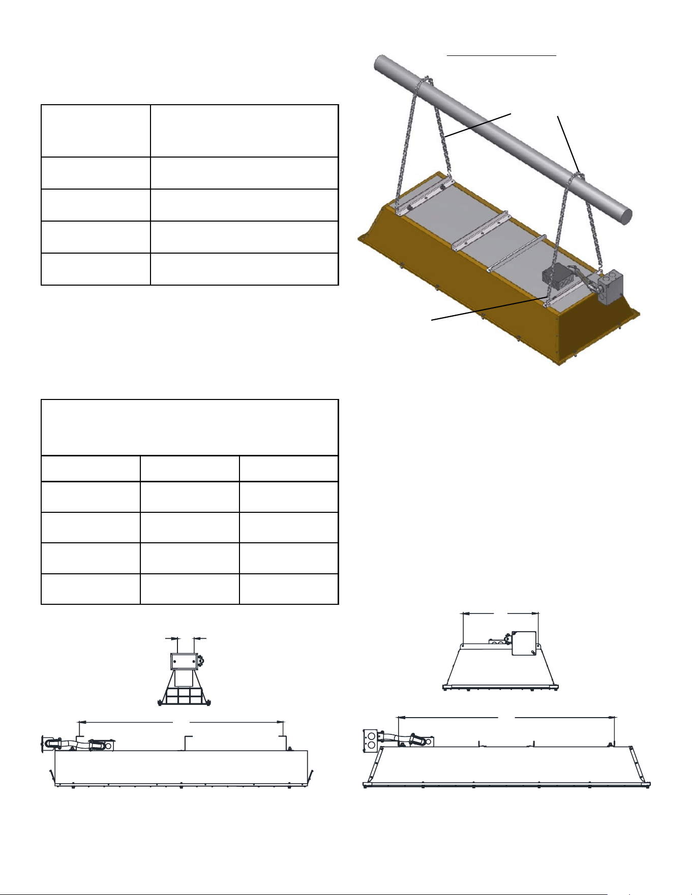
CHAIN HANGING
CHAIN
S-HOOK
Fixed-Mounting
B
B
A
FSS-14, FSS-31
FSS-43, FSS-95
A
ISSUE DATE 07-2015 REV. DATE ------------ REV. LEVEL: - ECO 1-7090 OIPM P/N 8419 PG 9 OF12
SERIES
RECOMMENDED
MOUNTING HEIGHTS
FSS-14 8-10 Ft.
FSS-31 8-12 Ft.
FSS-43 10-14Ft.
FSS-95 12-16Ft.
Mounting Centers
(In Inches)
Series Dim. A Dim. B
FSS-14 14-1/4 2-1/2
FSS-31 34-1/4 2-1/2
FSS-43 18-1/4 12-3/4
FSS-95 36 3/4 12-3/4
FOR ALL HEATERS
Wiring procedures and connections shall be in
accordance with the national and local authority
having jurisdiction. The FSS series heaters do not
have any on board controls and therefore must
be used in conjunction with an applicable control
center or be wired to a listed, properly rated safety
switch for on/off control.
Always disconnect the power at the circuit break-
er or disconnect switch before installing electric
power to the heater. If the breaker or disconnect
switch cannot be seen from where you will be
working, lock it in the open position and tag it to
prevent unexpected application of power. Failure
to do so could result in fatal electric shock. Do not
depend on a thermostat or other switch as the sole
means of turning off power to the heater. When
bringing supply wiring to the heater always route it
away from the area directly above the heater and
away from the sides of the heater where tempera-
tures may be dangerously high.
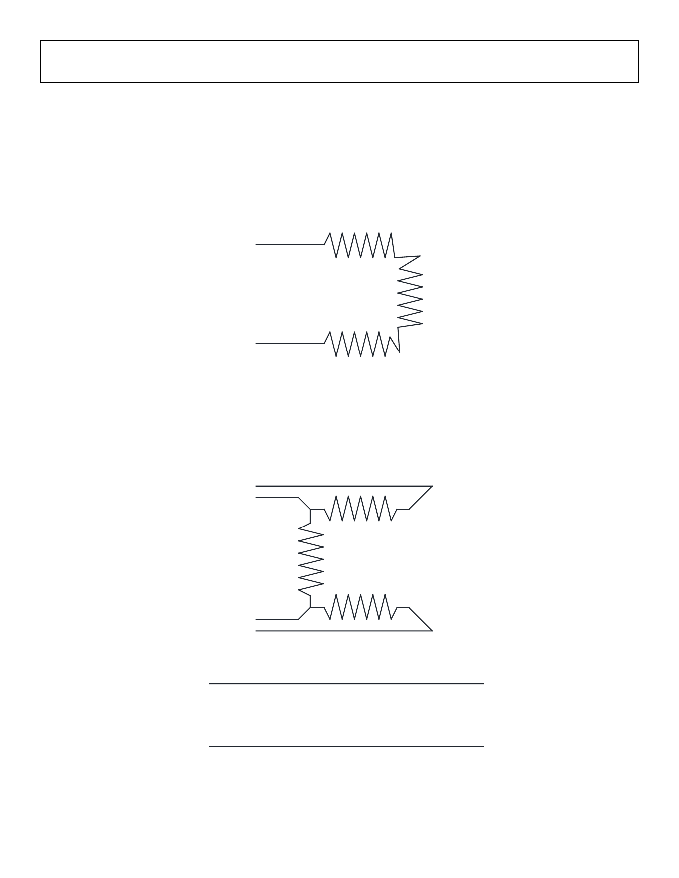
WIRING OF THE FSS SERIES HEATERS:
1. The FSS-14 and FSS-31 models are available
in single phase only. All FSS-43 and FSS-95
models (except the FSS-4327-1) and FSS-
9527-1) can be wired for single phase or three
phase applications. See wiring diagrams on
page 10.
2. Remove the cover from the terminal box.
3. Connect the lead wires to the 90°C rated sup-
ply wiring routed into the splice box with wire
nuts or other safe mechanical means. Black
and white supply leads can be connected to
either element lead wire. Be sure green lead
from supply and green (bonding) lead from the
terminal box are connected.
4. Reinstall splice box cover.
5. Apply power to circuit.
ISSUE DATE 07-2015 REV. DATE ------------ REV. LEVEL: - ECO 1-7090 OIPM P/N 8419 PG 10 OF12
INSTALLATION - WIRING
“Bonding is the intentional electrical connection
of all non-current carrying metal parts to the
equipment grounding (green) conductor of the
heater and then terminating this green conductor
to the green conductor of the power supply to form
a low-impedance path back to the power supply
so that safety devices (circuit breakers, fuses)
can quickly remove dangerous touch voltage from
these parts when a fault occurs.
Always securely connect the green conductor
from the power supply to the green conductor
of the heater.
ELECTRICAL SHOCK
HAZARD
• Serious injury or death may
occur.
• Disconnect heater and lock out
from electrical supply before
installing or servicing.
• Always securely connect
green wire on heater to
bonding (green) wire from
electrical supply.
When power is provided to these heaters the
heater elements will take several minutes to
achieve full infrared output that can be conrmed
by an orange to dull red glow on the element
surface.
The element under this condition is
operating between 1,500 and 1,600° F emitting
medium wavelength (approx. 3 microns or
millionths of a meter) infrared energy. This
energy, that can also be considered “radiation” is
not harmful, yet is very effective at heating
o
bjects and surfaces that are within the
line-of-sight of the elements and the heater’s
reective surfaces.
When power is provided or removed from these
heaters, you may hear unfamiliar sounds that are
caused by the expansion and contraction of metal
components in the heater. This is normal.
Pre-Season Maintenance and Annual Inspection
T
o ensure your safety and years of trouble-free operation from the heaters, periodic service and
inspections must be done by a trained maintenance person or licensed electrician.
To obtain maximum performance from your heater(s) each year, we recommend the following be
performed at the start of the heating season:
1. Disconnect power to heater at main panel. Be sure that heating elements have cooled down.
2. Clean housing surfaces with a damp cloth.
3. Blow or dust off the element.
4. Repair or replace damaged power cables.
5. DO NOT hose-down these heaters.
ISSUE DATE 07-2015 REV. DATE ------------ REV. LEVEL: - ECO 1-7090 OIPM P/N 8419 PG 11 OF12
OPERATION
BURN HAZARD
• Serious injury or death may
occur.
• Allow heater to fully cool after
power is removed (may take
minutes) before touching or
working on it.
MAINTENANCE
ISSUE DATE 07-2015 REV. DATE ------------ REV. LEVEL: - ECO 1-7090 OIPM P/N 8419 PG 12 OF12
1
2
3
4
FOR 3PH OPERATION
L1-1 & 4,L2-2,L3-3.
FOR 1PH OPERATION
L1-1 & 3, L2(N)-2 & 4.
WIRING SCHEMATIC
L1
L2(N)
FOR FSS-14, FSS-31 FSS-4327-1
AND FSS-9527-1 MODELS
FOR ALL OTHER MODELS
INSTALLATION WIRING (con’t.)