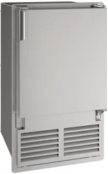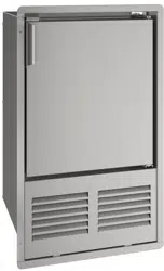
USER GUIDE & SERVICE MANUAL
Marine Series
●
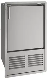
UMCR014
●
14” Crescent Ice Maker (115V)
USERGUIDE&SERVICEMANUAL
u-line.com
TableofContents
Intro
Safety
Safety and Warning
Disposal And Recycling
Installation
Environmental Requirements
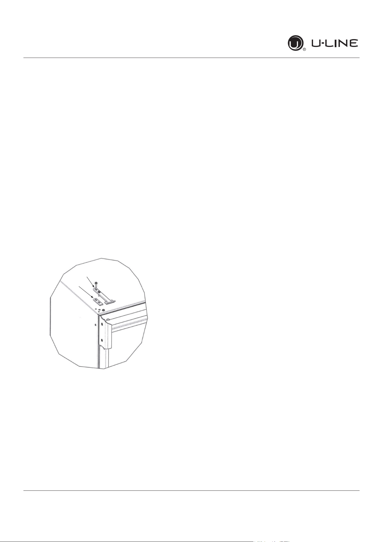
Electrical
Cutout & Product Dimensions
Water Hookup
General Installation
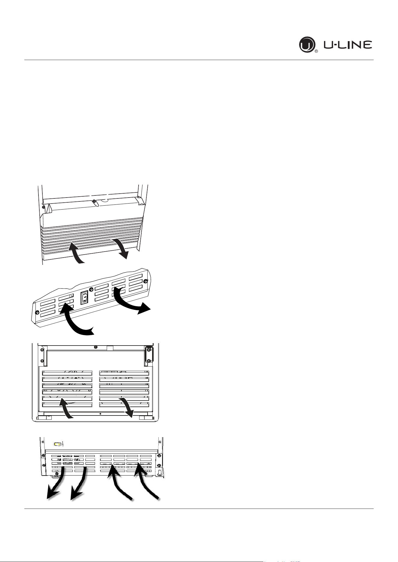
Grille Installation
Door Swing
Door Adjust
Maintenance
Door Latch
Cleaning
Cleaning Condenser
Extended Non-Use
Operating Instructions
First Use
Ice
Airflow and Product Loading
Service
Troubleshooting
Wire Diagram
Product Liability
Warranty Claims
Parts
Ordering Replacement Parts
System Diagnosis Guide
Compressor Specifications
Troubleshooting Extended
Defrost
Warranty
USER GUIDE
u-line.com
Introduction
WELCOME TO U-LINE
CongratulationsonyourU-Linepurchase.Yourproductcomesfromacompanywithover�vedecadesofpremiummodularice
making, refrigeration, and wine preservation experience. U-Line creates products focused on functionality, style, and inspired
innovations — paying close attention to even the smallest details. Applications include residential, outdoor, ADA height
compliant, marine, and commercial. Complete product categories include Beverage Centers, Wine Refrigerators, Ice Machines,
Refrigerators, Freezers, and Dispensers.
Ouradvancedrefrigerationsystems,largeandexiblecapacities,andBuilt-IntoStandOut
®
clean integrated look allow you
topreservetherightproduct,intherightplace,attherighttemperature.Since2014,U-LinehasbeenpartoftheMiddleby
familyofbrands.Allproductsaredesigned,engineered,andassembledinMilwaukee,Wisconsin,USA,andselectproducts
areavailableworldwide.
PRODUCT INFORMATION
Lookingforadditionalinformationonyourproduct?UserGuides,SpecSheets,CADDrawings,ComplianceDocumentation,
andProductWarrantyinformationareallavailableforreferenceanddownloadatu-line.com.
PROPERTY DAMAGE / INJURY CONCERNS
In the unlikely event property damage or personal injury is suspected related to a U-Line product, please take the following
steps:
1. U-LineCustomerCaremustbecontactedimmediatelyat+1.414.354.0300.
2. ServiceorrepairsperformedontheunitwithoutpriorwrittenapprovalfromU-Lineisnotpermitted.Iftheunithasbeen
alteredorrepairedinthe�eldwithoutpriorwrittenapprovalfromU-Line,claimswillnotbeeligible.
GENERAL INQUIRIES
U-Line Corporation
8900N.55thStreet
Milwaukee,Wisconsin53223USA
Monday-Friday8:00amto4:30pmCST
T:+1.414.354.0300
Email: sales@u-line.com
u-line.com
CONNECT WITH US
SERVICE & PARTS ASSISTANCE
Monday-Friday8:00amto4:30pmCST
T:+1.414.354.0300
ServiceEmail:onlineservice@u-line.com
Parts Email: [email protected]
Designed,engineeredandassembledinWI,USA
3
USER GUIDE
u-line.com
Safety and Warning
Safety and Warning
NOTICE
Please read all instructions before installing,
operating, or servicing the appliance.
Use this appliance for its intended purpose only and follow
these general precautions with those listed throughout this
guide:
SAFETY ALERT DEFINITIONS
Throughout this guide are safety items labeled with a
Danger, Warning, or Caution based on the risk type:
Danger means that failure to follow this safety
statement will result in severe personal injury or
death.
Warning means that failure to follow this safety
statement could result in serious personal injury
or death.
Caution means that failure to follow this safety
statement may result in minor or moderate
personal injury, property, or equipment damage.
This unit contains R600a (Isobutane) which is a
ammablehydrocarbon.Itissafeforregular
use. Do not use sharp objects to expedite
defrosting. Do not service without consulting the
“R600aspeci�cations”sectionincludedinthe
User Guide. Do not damage the refrigerant
circuit.
Service must be done by factory authorized
service personnel. Any parts shall be replaced
with like components. Failure to comply could
increase the risk of possible ignition due to
incorrect parts or improper service.
CALIFORNIA PROPOSITION 65
This product contains chemicals known to the
state of California to cause cancer and birth
defects or other reproductive harm.
www.P65warnings.CA.gov
This equipment is to be installed with adequate
backowprotectiontocomplywithapplicable
federal, state and local codes.
DANGER
!
DANGER
!
WARNING
!
CAUTION
!
CAUTION
!
WARNING
!
4
USER GUIDE
u-line.com
Disposal and Recycling
Disposal and Recycling
RISK OF CHILD ENTRAPMENT. Before you throw
awayyouroldrefrigeratororfreezer,takeo�
the doors and leave shelves in place so children
may not easily climb inside.
If the unit is being removed from service for disposal,
check and obey all federal, state, and local regulations
regarding the disposal and recycling of refrigeration
appliances, and follow these steps completely:
1. Remove all consumable contents from the unit.
2. Unplug the electrical cord from its socket.
3. Remove the door(s)/drawer(s).
DANGER
!
5
USERGUIDE
EnvironmentalRequirements
u-line.com
EnvironmentalRequirements
Thismodelisintendedforindoor/interiorapplicationsonly
andisnottobeusedininstallationsthatareopen/
exposedtonaturalelements.
Thisunitisdesignedtooperatebetween50°F(10°C)and
100°F(38°C).Higherambienttemperaturesmayreduce
theunit’sabilitytoreachlowtemperaturesand/orreduce
iceproductiononapplicablemodels.
Forbestperformance,keeptheunitoutofdirectsunlight
andawayfromheatgeneratingequipment.
Inclimateswherehighhumidityanddewpointsare
present,condensationmayappearonoutsidesurfaces.
Thisisconsiderednormal.Thecondensationwill
evaporatewhenthehumiditydrops.
CAUTION
!
Damagescausedbyambienttemperaturesof
40°F(4°C)orbelowarenotcoveredbythe
warranty.
6
USERGUIDE
Electrical
u-line.com
Electrical
WARNING
!
SHOCKHAZARD—ElectricalGrounding
Required.Neverattempttorepairorperform
maintenanceontheunituntiltheelectricityhas
beendisconnected.
Neverremovetheroundgroundingprongfrom
theplugandneveruseatwo-pronggrounding
adapter.
Altering,cuttingorremovingpowercord,
removingpowerplug,ordirectwiringcancause
seriousinjury,fire,lossofpropertyand/orlife,
andwillvoidthewarranty.
Neveruseanextensioncordtoconnectpowerto
theunit.
Alwayskeepyourworkingareadry.
NOTICE
Electricalinstallationmustobserveallstateand
localcodes.Thisunitrequiresconnectiontoa
grounded(three-prong),polarizedreceptacle
thathasbeenplacedbyaqualifiedelectrician.
Theunitrequiresagroundedandpolarized115VAC,
60 Hz,15Apowersupply(normalhouseholdcurrent).An
individual,properlygroundedbranchcircuitorcircuit
breakerisrecommended.AGFCI(groundfaultcircuit
interrupter)isusuallynotrequiredforfixedlocation
appliancesandisnotrecommendedforyourunitbecause
itcouldbepronetonuisancetripping.However,besure
toconsultyourlocalcodes.
SeeCUTOUT&PRODUCTDIMENSIONSforrecommended
receptaclelocation.
7
USER GUIDE
u-line.com
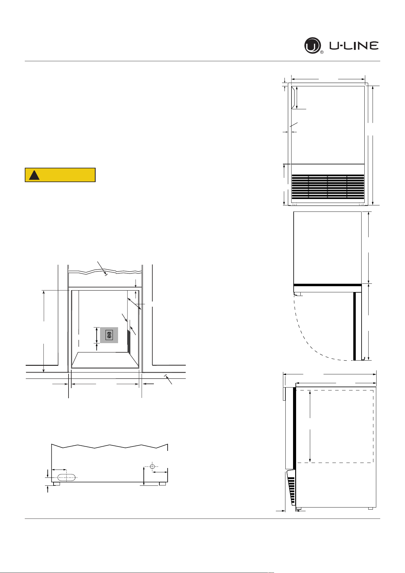
Cutout & Product Dimensions
Cutout & Product Dimensions
PREPARE SITE
Your U-Line product has been designed for either free-
standing or built-in installation. When built-in, your unit
does not require additional air space for top, sides, or
rear. However, the front grille must NOT be obstructed,
and clearance is required for an electrical connection in
the rear.
CAUTION
!
Unit can NOT be installed behind a closed cabinet
door.
CUTOUT DIMENSIONS
PRODUCT DIMENSIONS
REAR
FRONT
TOP
SIDE
Cutout
Height
25-1/16"
(637 mm)
18-1/2" (470 mm)
Filler Panel (Not Provided by U-Line) –
Needed to Attach Mounting Flange on Unit
Toe Kick
14-1/4"
(362 mm)
Cutout Width
3/4"
(19 mm)
Minimum Flange
Mounting Area
3/4" (19 mm) Minimum
Flange Mounting Area
3/4"
(19 mm)
Minimum Flange
Mounting Area
Preferred location
for water line and
electrical outlet is in
adjacent cabinet.
5/8"
(16 mm)
4"
(102 mm)
7"
(178 mm)
Minimum
1
⁄
”
(32 mm)
3 ⁄”
(95 mm)
4”
(102 mm)
2 ⁄8”
(73 mm)
Water Line
Power Cord
Flange
sides and bottom
24 ⁄”
(627 mm)
8 ⁄”
(222 mm)
14
⁄
”
(356 mm)
4 ⁄”
(119 mm)
⁄”
(19 mm)
⁄”
(17 mm)
14 ⁄
”
(367 mm)
15 ⁄8
”
(391 mm)
⁄4
”
(19mm)
17
⁄
”
(449 mm)
14
⁄
”
(367 mm)
2
⁄8
”
(60 mm)
14 ⁄8”
(365 mm)
8
USER GUIDE
u-line.com
Water Hookup
Water Hookup
PREPARE PLUMBING
The water valve uses a standard 1/4” (6.35 mm)
compressionfitting.U-Linerecommendsusingaccessory
waterhookupkit–part#ULAWATERHOOKUP.Thekit
includesa10’(3m)braidedflexiblewatersupplylineand
abrasshosefitting.
Plumbing installation must observe all state
and local codes. All water and drain connections
MUSTBEmadebyalicensed/qualiedplumbing
contractor. Failure to follow recommendations
and instructions may result in damage and/or
harm.
WaterSupplyConnection
Whenconnectingthewatersupply,pleasenotethe
following:
• Beforeinstallingtheunitandconnectingtothecold
watersupply,reviewthelocalplumbingcodes.
• The water pressure should be between a minimum of
20andamaximumof120psi(138and827kPa).
• ThewaterlineMUSThaveashut-o�valveinthe
supplyline.
• The water line should be looped into 2 coils. This
willallowtheunittoberemovedforcleaningand
servicing.Makecertainthatthetubingisnotpinched
ordamagedduringinstallation.
Connecttopotablewatersupplyonly.
Donotuseanyplasticwatersupplyline.Theline
isunderpressureatalltimes.Plasticmaycrack
orrupturewithageandcausedamagetoyour
home.
Donotusetapeorjointcompoundwhen
attachingabraidedexiblewatersupplyline
thatincludesarubbergasket.Thegasket
providesanadequateseal–othermaterials
couldcauseblockageofthevalve.
Failure to follow recommendations and
instructions may result in damage and/or harm,
oodingorvoidtheproductwarranty.
Use new hose set. Do not reuse old hose set.
Turno�watersupplyanddisconnectelectrical
supplytounitpriortoinstallation.
Usecautionwhenhandlingbackpanel.Theedges
couldbesharp.
Turno�watersupplyanddisconnectelectricalsupplyto
productpriortoattemptinginstallation.
1. Remove the back panel.
2. Locatewater
valve inlet and
connect to
valve.
3. Breakawayllerfeatureinbushingwithat
screwdriver.
4. Threadwaterlinethrough
back panel hole (with
bushing).
Note: Orientation of hole
and location of water line
clampmaybedi�erent
dependingonmodel.
5. Turnonwatersupplyand
check for leaks.
6. Reinstall back panel.
7. Loosenscrewonclamp,
threadwaterlinethrough
waterlineclamp,tighten
screw.
CAUTION
!
CAUTION
!
CAUTION
!
WARNING
!
Remove
withflat
screwdriver
Water line
Clamp
9
USER GUIDE
u-line.com
General Installation
General Installation
LEVELING INFORMATION
NOTICE
Because these units do not have leveling legs,
it is extremely important that they sit on a level
surface. If they are not level, the ice mold will not
�llevenly.
Usealeveltocon�rmthe
unitislevel.Levelshouldbe
placedalongtopedgeand
sideedgeasshown.
INSTALLATION
1. Pluginthepower/electricalcord.
2. Gentlypushtheunitintoposition.Becarefulnotto
entanglethecordorwaterline.
3. Re-checktheleveling,fromfronttobackandsideto
side.Makeanynecessaryadjustments.
4. Removeinteriorpackingmaterialandwipeoutthe
insideoftheunitwithaclean,water-dampenedcloth.
10
USER GUIDE
u-line.com
Grille Installation
Grille Installation
REMOVING AND INSTALLING GRILLE
Disconnect electric power to the unit before
removing the grille.
When using the unit, the grille must be installed.
WARNING
!
DONOTtouchthecondenser�ns.Thecondenser
�nsareSHARPandcanbeeasilydamaged.
Removing the grille
1. Disconnect power to the unit.
2. Open unit door.
3. Remove the center screw.
4. Remove grille by sliding grille up and pulling it toward
you.
Installing the grille
1. Open unit door.
2. Align grille with front of unit slide front tab on grille
behind front of base.
3. Install center screw.
4. Reconnect power to the unit.
WARNING
!
3
11
USER GUIDE
u-line.com
Door Swing
Door Swing
This unit requires zero clearance for the door to open 90
o
when installed adjacent to cabinets. If installing the unit
next to a wall, the door handle requires 2-1/8” (54mm)
clearance.
Wall
Stainless Steel, Black and White
90°
Door Swing
2-1/8" Min.
(54 mm)
12
USER GUIDE
u-line.com
Door Adjustments
Door Adjustments
DOOR ALIGNMENT AND ADJUSTMENT
Align and adjust the door if it is not level or is not sealing
properly. If the door is not sealed, the unit may not cool
properly, or excessive frost may form in the interior.
NOTICE
Properly aligned, the door’s gasket should be
�rmlyincontactwiththecabinetalltheway
aroundthedoor(nogaps).Carefullyexaminethe
door’sgaskettoensurethatitis�rmlyincontact
withthecabinet.Alsomakesurethedoorgasket
isnotpinchedonthehingesideofthedoor.
To align and adjust the door:
1. Loosen (do not remove) top and bottom hinge screws
using a Torx T-25 screwdriver on the top and a 1/4”
socket on the bottom.
2. Align door squarely with cabinet.
3. Makesuregasketisrmlyincontactwithcabinetall
the way around the door (no gaps).
4. Tighten bottom hinge screws.
5. Tighten top hinge screws.
REVERSING THE DOOR
Location of the unit may make it desirable to mount the
door on the opposite side of the cabinet.
The hinge hardware will be removed and reinstalled on the
opposite side of the cabinet.
Removedoorlatchassembly
Remove door latch assembly and reinstall on opposite side
of door (see DOOR LATCH).
TO REVERSE THE DOOR
Removetophingeanddoor:
1. Hold door to keep it
from falling.
2. Remove top hinge
from cabinet using a
Torx T-25 screwdriver
to remove three
screws.
3. Removedoorbytiltingforwardandliftingdooro�
bottom hinge. Retain shoulder washers; they will be
reused.
4. Remove three screws from hinge holes on the opposite
side.
5. Install three screws into holes where the hinge was
removed.
Movebottomhinge:
1. Remove bottom hinge from cabinet using a 1/4”
socket.
Note:Ifunitisequippedwithaplasticgrille,
removethetopcenterscrewandthebottom
screwonthehinge�rst.Removegrilleandother
hingescrew,andproceedtoStep2.
2. Remove corresponding screws on opposite side of
cabinet.
3. Install bottom hinge on opposite side.
Prepare door:
1. Take out the two screws holding the stainless handle.
Remove handle and reinstall the screws into the holes.
2. On the opposite side of the door, remove the two
handle screws and use them to install handle.
Hinge screws
Remove two
hinge screws
Center Screw
13
USER GUIDE
u-line.com
Door Adjustments
3. Remove plastic plug on top of door and save for re-
installation on opposite side.
4. Relocate plastic bushings on top and bottom of door to
opposite side. Clean out bushing hole in door bottom
with a screwdriver if necessary.
Install top hinge:
1. Remove pivot screw from top hinge, invert screw and
reinstall pivot screw in top hinge.
2. Lift the door onto the bottom hinge.
3. Align edge of the hinge with the outer edge of the
unit.
4. Tighten three screws.
5. Insert plastic plug in opposite end of door.
Installgrilleifapplicable.
Align and adjust the door:
Align and adjust the door (see DOOR ALIGNMENT AND
ADJUSTMENT)
Plastic
Hole Plug
Plastic
Hole Plug
Hinge
Screw
Right Side
Door Swing
Right Side
Hinge
Invert
Screw
Invert
Hinge
Left Side
Door Swing
14
USER GUIDE
u-line.com
Door Latch
Door Latch
The door latch assembly included with your unit can
be installed to prevent the door from opening when the
vehicle is in motion.
To install, perform the following:
1. Remove the two outer most screws from the non-
hinge side.
2. Place spacer (2) over mounting holes. Place latch (1)
on top of spacer (2).
Note: Spacer (2) only required if included with
unit.
3. Re-install the screws, but do not tighten all the way.
4. Verify door latch engagement and adjust as necessary.
5. Tighten screws.
Door latch can be used to prop door open approximately
1/2” (13 mm) when unit is not in use.
2
1
15
USERGUIDE
FirstUse
u-line.com
FirstUse
Initialstartuprequiresnoadjustments.
NOTICE
U-Linerecommendsdiscardingtheiceproduced
duringthefirsttwotothreehoursofoperation
toavoidpossibledirtorscalethatmaydislodge
fromthewaterline.
Toturntheunitonoroff:
Presstherockerswitchlocatedinsidethedooronthe
frontpanel,orbehindthegrille.
OFF
ON
16
USERGUIDE
Ice
u-line.com
Ice
ICEMAKEROPERATION
Whentheicebucketisfull,theicemakingmechanismwill
shutoff.However,therefrigerationsystemwillcontinue
tocoolandmaintaintheicesupply.
NOTICE
Donotplacecansorbottlesintheice
compartmentbecausetheywillfreeze.
Toturnofficeproduction:
Raisethebinarminto
anuprightandlockedposition.Theunitwillpreserve
temperatureforicestorage.
NOTICE
Ifnotintendingtousetheicemaker,turnthe
watersupplyvalveoff.Itisalsoimportantto
raisethebinarmoftheicemaker(seeabove).
Failuretoraisethebinarmmayresultindamage
tothewatervalve.
Certainsoundsarenormalduringtheunit’soperation.You
mayhearthecompressororfanmotor,thewatervalve,
oricedroppingintotheicebucket.
CAUTION
!
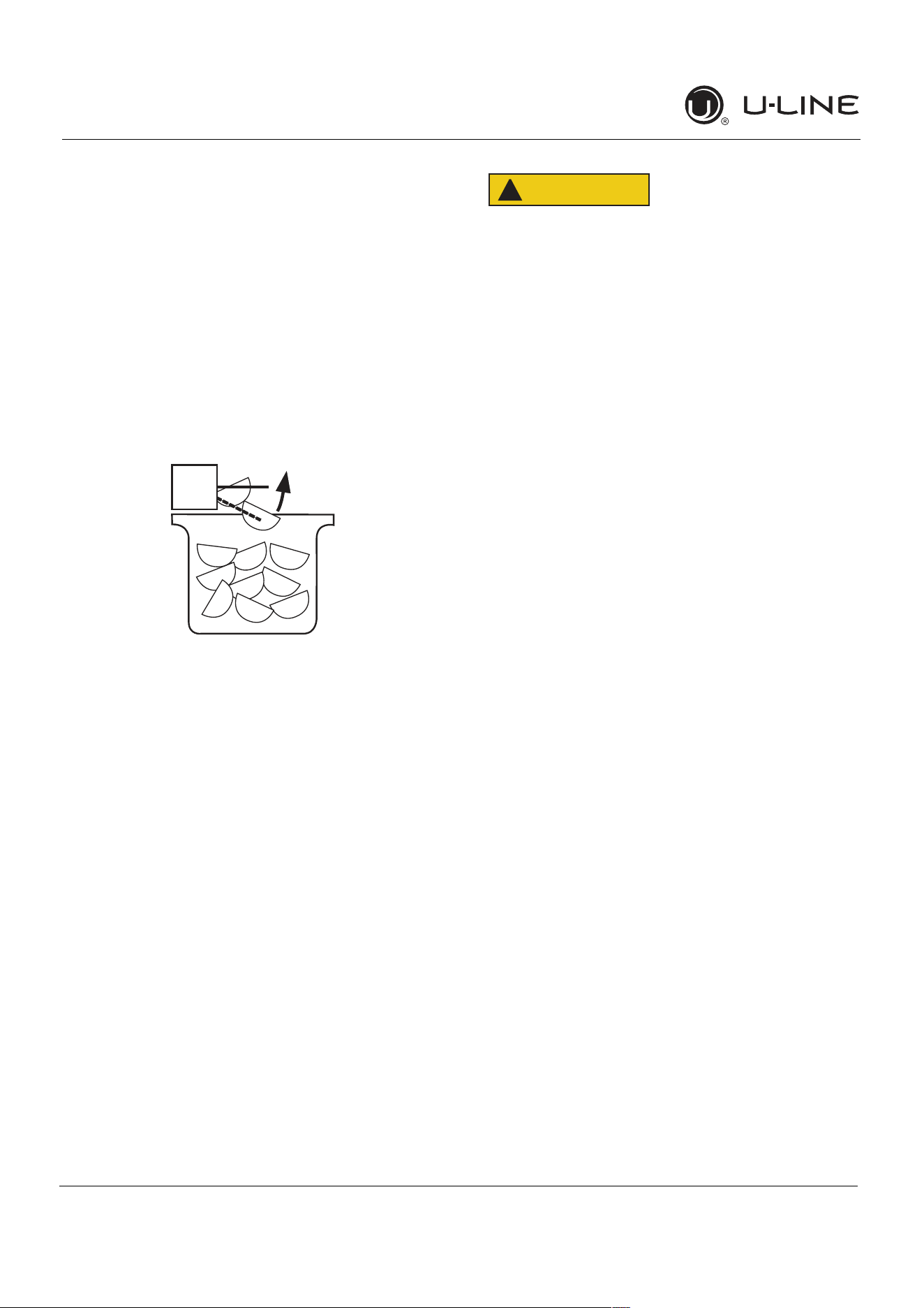
NEVERuseanicepick,knifeorothersharp
instrumenttoseparatecubes.Shaketheice
bucketinstead.
Duringperiodsoflimiteduseorhighambient
temperatures,itiscommonforcubestofusetogether.
Gentlyshakethebuckettobreakapartcubes.Ifnotusing
theicemakerregularly,emptytheicebucketperiodically
toensurefreshcubes.
Itisnormalforcubestoappearcloudy.Thecauseisair
trappedinthewaterbecauseoffastfreezing.Itisnot
causedbythehealth,tasteorchemicalmakeupofthe
water.Itisthesameairthatisineveryglassofwateryou
drink.
Removetheicebucketforemptyingandcleaning.To
removetheicebucket,raisethebinarmandremovethe
bucketfromtheicecompartment.Usetheicebucketfor
icestorageonly.
OFF
ON
17
USERGUIDE
Ice
u-line.com
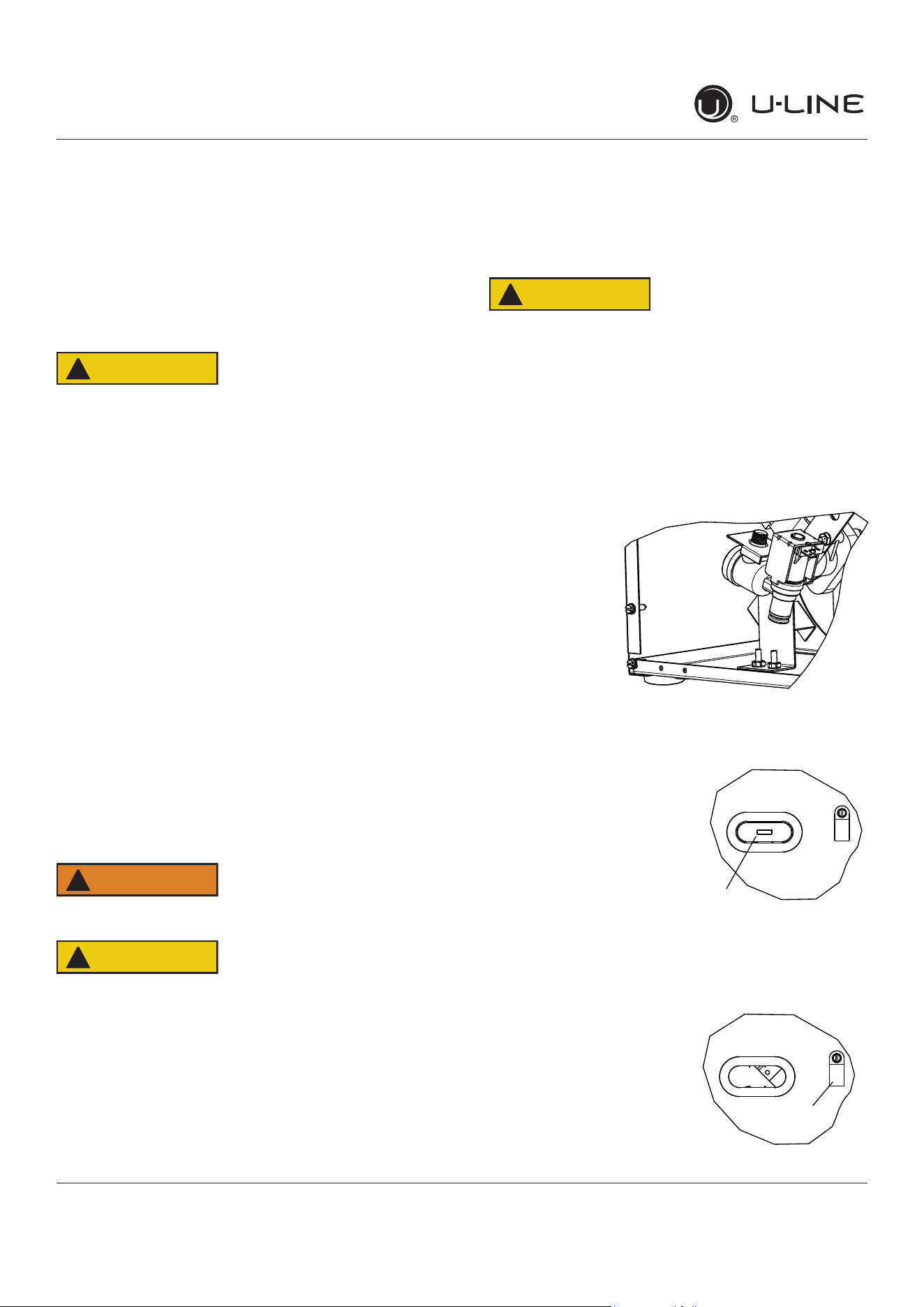
ICEMAKERADJUSTMENT
IceCubeThicknessAdjustment
Interval-AsRequired
Onicemakerequippedmodels,adjustthecubesizeby
changingwateramountinjectedintotheicemaker
assemblyasfollows:
1. Removetheicemakerassemblycover(1).
2. Findtheadjustingscrewontheicemakerassembly
controlbox(2).Theadjustingscrewisjustbelowthe
minus(-)andplus(+)signsonthecontrolbox.
CAUTION
!
Toolargeofanadjustmenttothescrewcan
causethewatertooverflowtheicemakerand
cancausepropertydamage.
3. Turntheadjustingscrewtowardtheminus(-)sign
(clockwise)forsmallercubesortowardtheplus(+)
sign(counterclockwise)forlargercubes.
4. Installtheicemakerassemblycover.
ADJUSTINGICEHARVEST
1. Removethefrontgrille(seeGRILLEINSTALLATION).
2. Usingaflattipscrewdriver,turntheadjustingscrew
(3) asmallincrementclockwiseforaCOLDERsetting
(slowericeproduction)orcounterclockwisefora
WARMERsetting(fastericeproduction).
3. Reinstallthefrontgrille(twoscrews).
1
2
C
O
L
D
E
R
Warmer Colder
3
1
2
18
USER GUIDE
u-line.com
Air�owandProductLoading
Theunitrequiresproperair�owtoperformatits
highesteciency.Donotblockthefrontgrilleat
anytime,ortheunitwillnotperformasexpected.
Donotinstalltheunitbehindadoor.
Dependingonthemodel,yourgrillemaynotmatch
exactlywiththebelowillustrations.
NOTICE
Air�owandProductLoading
19
USERGUIDE
Cleaning
u-line.com
Cleaning
EXTERIORCLEANING
VinylClad(BlackorWhite)Models
Cleansurfaceswithamilddetergentandwarmwater
solution.Donotusesolvent-basedorabrasivecleaners.
Useasoftspongeandrinsewithcleanwater.Wipewitha
soft,cleantoweltopreventwaterspotting.
Cleananyglasssurfaceswithanon-chlorineglass
cleaner.
StainlessModels
Stainlessdoorpanels,handlesandframescandiscolor
whenexposedtochlorinegas,poolchemicals,saltwater
orcleanerswithbleach.
Keepyourstainlessunitlookingnewbycleaningwitha
goodqualityall-in-onestainlesssteelcleanerandpolish
monthly.ForbestresultsuseClaire
®
StainlessSteel
PolishandCleaner.Comparableproductsareacceptable.
Frequentcleaningwillremovesurfacecontaminationthat
couldleadtorust.Someinstallationsmayrequirecleaning
weekly.
Donotcleanwithsteelwoolpads.
Donotusestainlesssteelcleanersorpolisheson
anyglasssurfaces.
Cleananyglasssurfaceswithanon-chlorineglass
cleaner.
Donotusecleanersnotspecificallyintendedfor
stainlesssteelonstainlesssurfaces(this
includesglass,tileandcountercleaners).
Ifanysurfacediscoloringorrustingappears,cleanit
quicklywithBon-Ami
®
orBarkeepersFriendCleanser
®
andanonabrasivecloth.Alwayscleanwiththegrain.
AlwaysfinishwithClaire
®
StainlessSteelPolishand
Cleanerorcomparableproducttopreventfurther
problems.
UsingabrasivepadssuchasScotchBrite™will
causethegraininginthestainlesstobecome
blurred.
Rustnotcleaneduppromptlycanpenetratethe
surfaceofthestainlesssteelandcomplete
removaloftherustmaynotbepossible.
IntegratedModels
Tocleanintegratedpanels,usehouseholdcleanerperthe
cabinetmanufacturer’srecommendations.
INTERIORCLEANING
Disconnectpowertotheunit.
Cleantheinteriorandallremovedcomponentsusinga
mildnonabrasivedetergentandwarmwatersolution
appliedwithasoftspongeornon-abrasivecloth.
Rinsetheinteriorusingasoftspongeandcleanwater.
Donotuseanysolvent-basedorabrasive
cleaners.Thesetypesofcleanersmaytransfertasteto
theinteriorproductsanddamageordiscolortheinterior.
20
USERGUIDE
Cleaning
u-line.com
DEFROSTING
ManualDefrostModels
Thisunitisamanualdefrostmodelandwillrequire
occasionaldefrosting.Whenthereisbuild-upof1/4"
(6 mm)ormoreoffrost,manuallydefrosttheunit.
CAUTION
!
DONOTuseanicepickorothersharp
instrumenttohelpspeedupdefrosting.These
instrumentscanpuncturetheinnerliningor
damagethecoolingunit.DONOTuseanytypeof
heatertodefrost.Usingaheatertospeedup
defrostingcancausepersonalinjuryand
damagetotheinnerlining.
Todefrost:
1. Disconnectpowertotheunit.
2. Removeicebucketanddiscardice.
3. Placetowelorotherabsorbentmaterialonbottomof
icebin.
4. Filltheicebuckethalffullwithwarm,nothotwater.
Thiswillhelptheunitdefrostfaster.
5. Placetheicebucketbackintotheunitontopofthe
towelorotherabsorbentmaterial.
6. Propthedoorinanopenposition(2in.[50mm]
minimum).
7. Afterabout1hourremovetheicebinanddiscard
water.
8. Allowthefrosttomeltnaturally.
9. Afterthefrostmeltscompletelycleantheinteriorand
allremovedcomponents.(SeeINTERIORCLEANING).
NOTICE
DONOTcleanicebucketusingadishwasher.The
bucketisnotdishwashersafeandwillbe
damaged.
10.Whentheinteriorisdry,reconnectpowerandturnunit
on.
NOTE:Tosafeguardagainstcontaminatesinice,discard
firstthreebatchesoficeafterdefrosting.
21
USER GUIDE
u-line.com
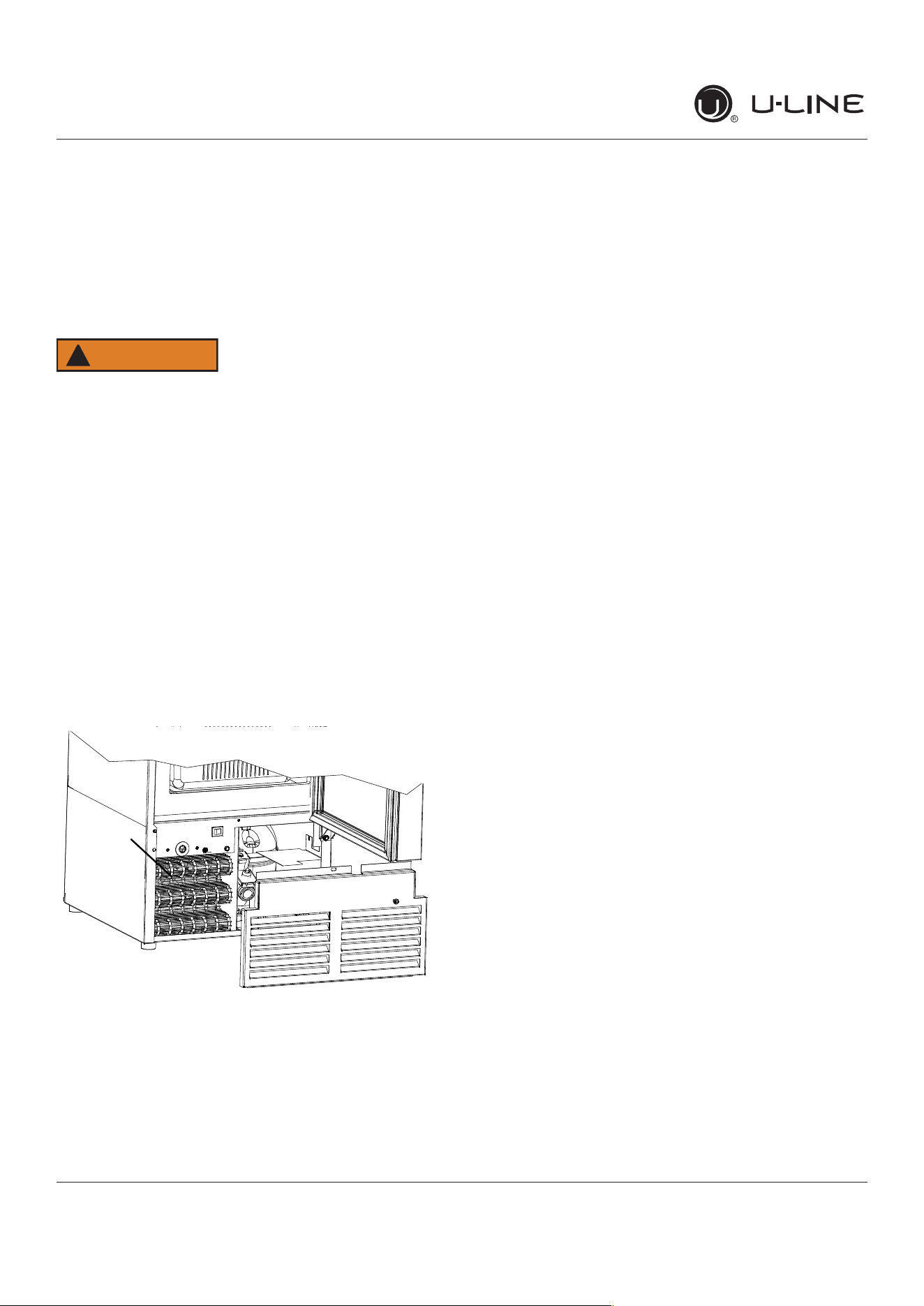
Cleaning Condenser
Cleaning Condenser
INTERVAL - EVERY SIX MONTHS
Tomaintainoperationale�ciency,keepthefrontgrillefree
ofdustandlint,andcleanthecondenserwhennecessary.
Dependingonenvironmentalconditions,moreorless
frequentcleaningmaybenecessary.
WARNING
!
Disconnect electric power to the unit before
cleaning the condenser.
NOTICE
DO NOT use any type of cleaner on the condenser
unit. Condenser may be cleaned using a vacuum,
soft brush, or compressed air.
1. Removethegrille.SeeGRILLEINSTALLATION).
2. Cleanthecondensercoilusingasoftbrushorvacuum
cleaner.
3. Installthegrille.
CONDENSER
22
USER GUIDE
u-line.com
Extended Non-Use
Extended Non-Use
VACATION/HOLIDAY, PROLONGED SHUTDOWN
The following steps are recommended for periods of
extended non-use:
1. Remove all consumable content from the unit.
2. Disconnect the power cord from its outlet/socket
and leave it disconnected until the unit is returned to
service.
3. Turno�thewatersupply.
4. Ificeisontheevaporator,allowicetothawnaturally.
5. Cleananddrytheinteriorofthecabinet.Ensureall
water has been removed from the unit.
6. Disconnect the water and drain line (if applicable)
making sure all water is removed from the lines.
7. The door must remain open to prevent formation of
mold and mildew. Open door a minimum of 2” (50
mm)toprovidethenecessaryventilation.
WINTERIZATION
If the unit will be exposed to temperatures of 40°F (5°C)
or less, the steps above must be followed. In addition,
P60 drain pumps in clear ice machines must be drained
according to the following procedure:
1. Remove the drain pump from the ice machine.
2. Drainthewaterinthepump’sreservoirbyturningthe
pump upside down and allowing the water to drain
throughthepump’sinletandventtubettings.
3. After water is drained, reinstall the drain pump and
reattach all connections.
For questions regarding winterization, please call
U-Line at 414.354.0300.
CAUTION
!
Damage caused by freezing temperatures is not
covered by the warranty.
Do not put anti-freeze in your unit.
23
USER GUIDE
Troubleshooting 1
u-line.com
SAFETY INSTALLATION & INTEGRATION OPERATING INSTRUCTIONS MAINTENANCE SERVICE
Troubleshooting
BEFORE CALLING FOR SERVICE
If you think your U-Line product is malfunctioning, read
the CONTROL OPERATION section to clearly understand
the function of the control.
If the problem persists, read the NORMAL OPERATING
SOUNDS and TROUBLESHOOTING GUIDE sections below
to help you quickly identify common problems and
possible causes and remedies. Most often, this will resolve
the problem without the need to call for service.
IF SERVICE IS REQUIRED
If you do not understand a troubleshooting remedy, or
your product needs service, contact U-Line Corporation
directly at +1.414.354.0300
When you call, you will need your product Model and
Serial Numbers. This information appears on the Model
and Serial number plate located on the upper right or rear
wall of the interior of your product.
NORMAL OPERATING SOUNDS
All models incorporate rigid foam insulated cabinets to
provide high thermal efficiency and maximum sound
reduction for its internal working components. Despite this
technology, your model may make sounds that are
unfamiliar.
Normal operating sounds may be more noticeable because
of the unit’s environment. Hard surfaces such as cabinets,
wood, vinyl or tiled floors and paneled walls have a
tendency to reflect normal appliance operating noises.
Listed below are common refrigeration components with a
brief description of the normal operating sounds they
make. NOTE: Your product may not contain all the
components listed.
Compressor: The compressor makes a hum or pulsing
sound that may be heard when it operates.
Evaporator: Refrigerant flowing through an evaporator
may sound like boiling liquid.
Condenser Fan: Air moving through a condenser may
be heard.
Automatic Defrost Drain Pan: Water may be heard
dripping or running into the drain pan when the unit is
in the defrost cycle.
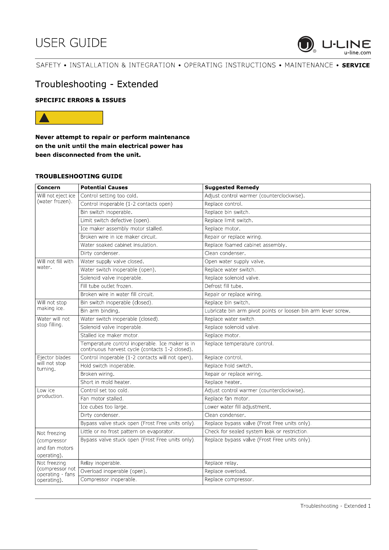
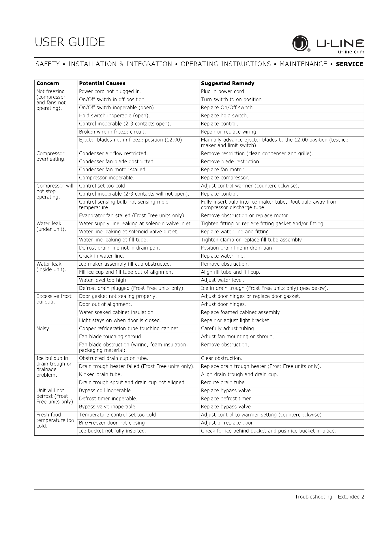
TROUBLESHOOTING GUIDE
DANGER
!
ELECTROCUTION HAZARD. Never attempt to
repair or perform maintenance on the unit
before disconnecting the main electrical power.
Troubleshooting - What to check when problems occur:
Problem Possible Cause and Remedy
Light Remains
on When Door
Is Closed.
Turn off light switch if equipped.
Check reed switch.
Unit Develops
Frost on
Internal
Surfaces.
Frost on the rear wall is normal and will melt
during each off cycle.
If there is excessive build-up of 1/4" or more,
manually defrost the unit.
Ensure the door is closing and sealing
properly.
High ambient temperature and excessive
humidity can also produce frost.
Unit Develops
Condensation
on External
Surfaces.
The unit is exposed to excessive humidity.
Moisture will dissipate as humidity levels
decrease.
Product Is
Freezing.
Because product in contact with the rear wall
may freeze, ensure no product is touching the
rear wall.
Adjust the temperature to a warmer set point.
24
USER GUIDE
Troubleshooting 2
u-line.com
SAFETY INSTALLATION & INTEGRATION OPERATING INSTRUCTIONS MAINTENANCE SERVICE
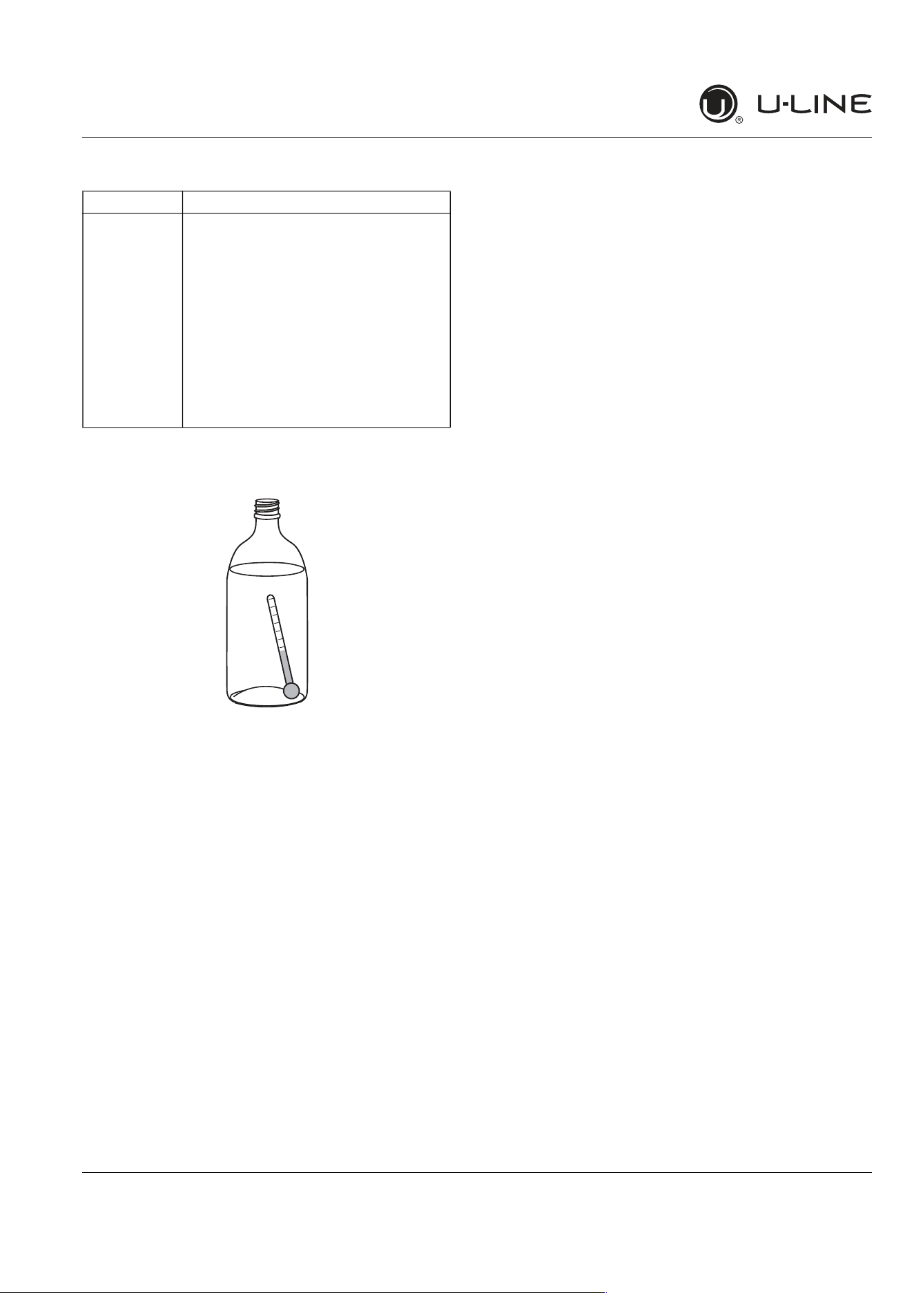
CHECKING PRODUCT TEMPERATURE
To check the actual product temperature in the
unit:
1. Partially fill a plastic (nonbreakable) bottle with water.
2. Insert an accurate thermometer.
3. Tighten the bottle cap securely.
4. Place the bottle in the desired area for 24 hours.
5. Avoid opening the unit during the testing period.
6. After 24 hours, check the temperature of the water. If
required, adjust the temperature control in a small
increment (see CONTROL OPERATION).
Causes which affect the internal temperatures of
the cabinet include:
Temperature setting.
Ambient temperature where installed.
Installation in direct sunlight or near a heat source.
The number of door/drawer openings and the time the
door/drawer is open.
The time the internal light is illuminated. (This mainly
affects product on the top rack or shelf.)
Obstruction of front grille or condenser.
Product is Not
Cold Enough.
Air temperature does not indicate product
temperature. See CHECKING PRODUCT
TEMPERATURE below.
Adjust the temperature to a cooler set point.
Ensure unit is not located in excessive
ambient temperatures or in direct sunlight.
Ensure the door is closing and sealing
properly.
Ensure the interior light has not remained on
too long.
Ensure nothing is blocking the front grille,
found at the bottom of the unit.
Ensure the condenser coil is clean and free of
any dirt or lint build-up.
Problem Possible Cause and Remedy
25
USER GUIDE
SAFETY • INSTALLATION & INTEGRATION • OPERATING INSTRUCTIONS • MAINTENANCE • SERVICE
u-line.com
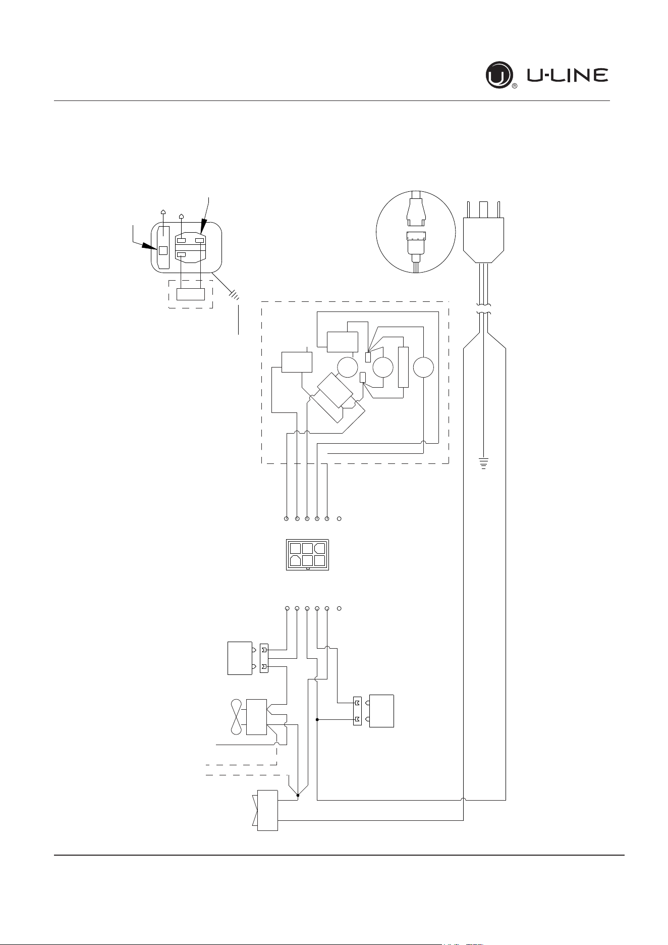
Wire Diagram 1
42312_C WIRING DIAGRAM
NEUTRAL WHITE
(DARK BLUE)
BLACK
(BROWN)
RELAY
EMBRACO
COMPRESSOR
GREEN or
GREEN W/ YELLOW
GROUND:
OVERLOAD
CAP
EMU
ONLY
MANUAL CONTROL ICEMAKER & COMBO
ROCKER
SWITCH
COND
FAN
WATER
VALVE
SEE COMPRESSOR
DIAGRAMS
BROWN
(ORANGE)
LIGHT BLUE
BLUE
(LIGHT BLUE)
WHITE
(DARK BLUE)
BLACK (BROWN)
BLACK
(BROWN)
WHITE
(DARK BLUE)
BIN
SW
NO
NC
C
WATER
SW
NC
NO
C
H
O
L
D
S
W
N
O
N
C
C
CAM
3 RPM
MOTOR
LIMIT
SW
MOLD HEATER
YELLOW
BLACK
RED
WHITE
WHITE
(DARK BLUE)
BROWN
YELLOW
RED
BROWN
(ORANGE)
BLACK
(BROWN)
BROWN W/YELLOW
RED
YELLOW
BROWN
BLACK
BROWN
OR
A
N
GE
OR
B
LUE
BLACK
OR BLUE
OR
ALL OTHER MODELS
ICEMAKER
BI1215 ONLY
CONTROL
POWER CORD ASSEMBLY
GROUND:
GREEN or GREEN W/ YELLOW
115
VOLT
PLUG
220-240 VOLT
PLUG
BLACK-HOT
(SMOOTH)
BLACK-NEUTRAL
(RIBBED)
BLACK
(BROWN)
WHITE
(DARK BLUE)
1
3
6
4
4
1
5
3
2
6
4
1
5
3
2
6
Wire Diagram
26
USER GUIDE
Product Liability 1
u-line.com
SAFETY INSTALLATION & INTEGRATION OPERATING INSTRUCTIONS MAINTENANCE SERVICE
Product Liability
Field service technicians are authorized to make an initial
assessment in the event of reported damages. If there are
any questions about the process involved, the technician
should call U-Line for further explanation.
While inspecting for defects or installation issues, photos
should be taken to document any damages or issues
found.
During the assessment, if the service technician is able to
find the source of the damage and it can be resolved by
replacement of a part, the servicer is authorized to
replace the part in question. The part that caused the
damage must be returned to U-Line in its entirety. The
part must be clearly labeled with the serial number of the
unit it was removed from, the date, and the servicer who
removed the part.
If the service technician determines the damage is the
result of installation issues (water connection/drain, etc.),
the consumer would be notified and the issues shall be
resolved at the direction of the consumer.
If damage is evident and the service technician is unable
to find the source, U-Line must be contacted at 1-800-
799-2547 for further direction
8900 N. 55th Street Milwaukee, WI 53223
T: +1.414.354.0300 F: +1.414.354.354.5696
Website: www.u-line.com
Right product. Right place.
Right temperature Since 1962.
27
USER GUIDE
Warranty Claims 1
u-line.com
SAFETY INSTALLATION & INTEGRATION OPERATING INSTRUCTIONS MAINTENANCE SERVICE
Warranty Claims
The following information defines the parameters for filing
a warranty claim:
Valid serial number needed
Valid model number needed
Narda (or equivalent) form or submitted online at
www.u-line.com
60 day submittal deadline from date of completed
service
Only one repair or unit per warranty claim
Refrigerant should be labeled and included on the labor
submittal
Door and water level adjustments are covered 30 days
from install date.
Serial Number Requirements:
A typical serial number is shown above. The first two
digits of the first segment, 14, represents the production
year. The number between the dashes, 12, represents the
production month. In most cases, warranty status can be
verified by the production date information within the
serial number.
Alternatively, a Proof of Purchase (or equivalent) may
submitted with the warranty claim to document
warranty status. We also accept the following
information to verify warranty status:
New Construction Occupancy Documents
Closing Paperwork
Final Billing – Remodel
Noting all of the following on the warranty claim will be
considered proof of purchase, hard copy will not be
required:
Name of the selling Dealer
Date of purchase/installation
Order or Invoice number (if available)
Description of document reviewed (i.e. store receipt,
closing paperwork, etc)
Parts and labor claims are paid separately. Indicate part
numbers and description for parts used in the warranty
repair. Include the purchase invoice and name of the parts
supplier used to procure the parts.
14 30911 12 X X X X
Year
Month
28
ULN-SS1095FC-03A
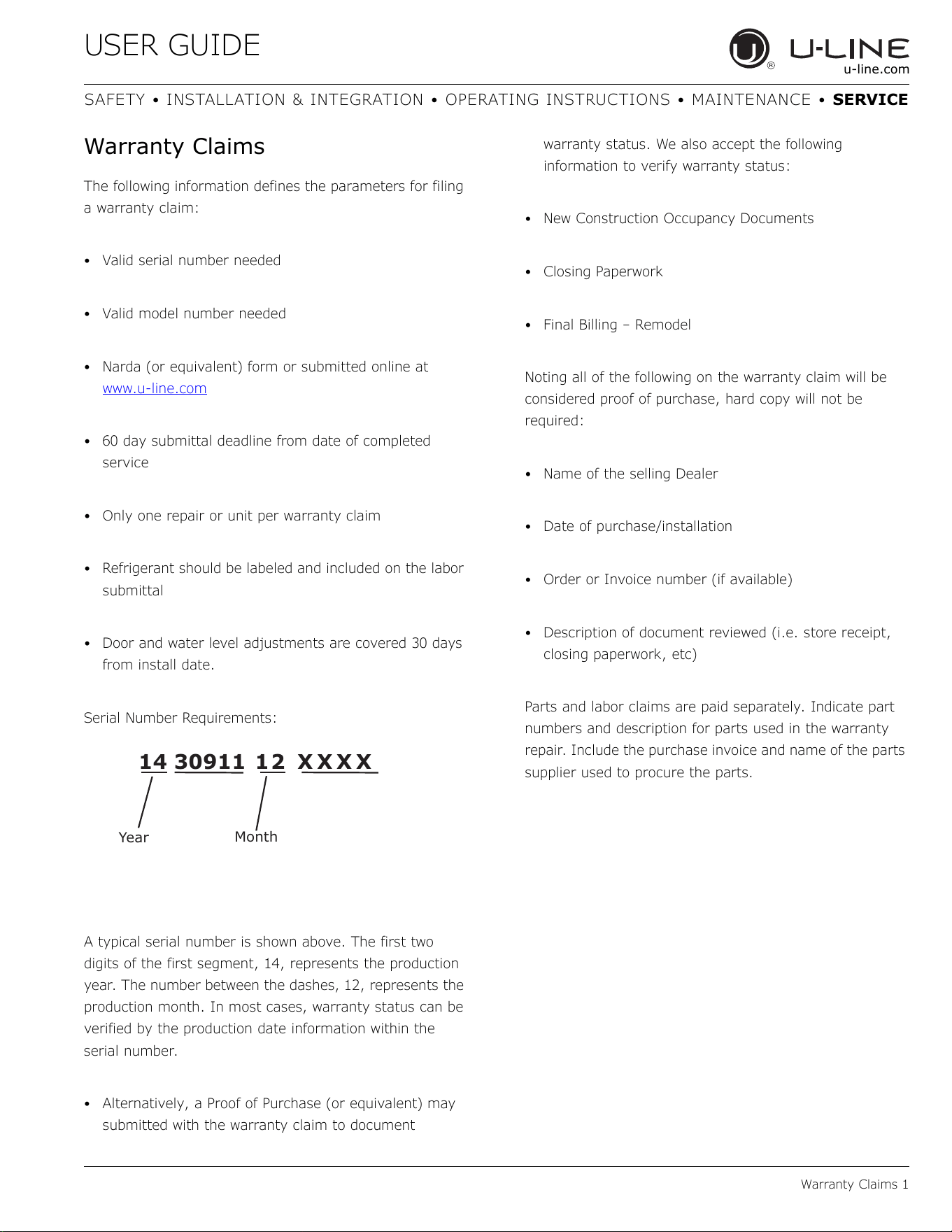
Item Description U-Line P/N
1 Back panel 80-54614-00
2 Compression nut/sleeve 80-54355-00
3 Compressor electricals only 80-54377-00
4 Compressor w/electricals 80-54376-00
5 Condenser assembly 80-54601-00
6 Condenser fan blade 80-54379-00
7 Condenser fan motor 80-54378-00
8 Control assembly 80-54590-00
9 Door assembly w/o hinges 80-54648-00
10 Gasket, door 80-54653-00
11 Drier 80-54055-00
12 Evap/cabinet assembly 80-54659-00
13 Feet (4) 80-54563-00
14 Flange assembly, ss, fc 80-54655-00
15 Grille w/screws 80-54657-00
16 Hinges(2) w/screws 80-54658-00
17 Ice bucket 80-54611-00
18 Ice maker assembly 80-5437200
19 Packaging 80-54612-00
20 Power cord 80-54597-00
21 Rocker switch 80-54105-00
22 Travel handle w/screws 80-54607-00
23 Travel latch assy 80-54572-00
24 Water line assembly 80-54613-00
25 Water valve assembly 80-54356-00
26 Water valve assembly 3/8 80-54624-00
27 Faceplate 115V 80-54523-00
Parts
Parts 1
1
4
5
6
7
8
9
13
16
17
18 27
3
25
15
14
12
11
10
21
22
23
29
USER GUIDE
Ordering Replacement Parts 1
u-line.com
SAFETY INSTALLATION & INTEGRATION OPERATING INSTRUCTIONS MAINTENANCE SERVICE
Ordering Replacement Parts
If you have a purchasing account, please utilize our
service website to order parts.
Orders may also be placed by Fax or phone. See our
contact information below:
www.U-LineService.com (with service login)
FAX Number: +1.414.354.5696
Phone Number: +1.800.779.2547
NOTICE
Use only genuine U-Line replacement parts. The
use of non-U-Line parts can reduce speed of ice
production, cause water to overflow from ice
maker mold, damage the unit, and void the
warranty.
Warranty parts will be shipped at no charge after U-Line
confirms warranty status. Please provide the model, serial
number, part number and part description. Some parts
will require color or voltage information.
If U-Line requires the return of original parts, we will
inform you when the parts order is taken. This
requirement will be noted on your packing list. A prepaid
shipping label will be included with the replacement part.
Please enclose a copy of the parts packing list and any
labor claims with your return. Please be sure the model
and serial numbers are legible on the paperwork. Tag the
part with the reported defect.
When ordering a non-warranty part, you will need an open
account and tax exemption on file at U-Line. Another
option would be to visit www.u-line.com to locate an
authorized parts distributor in your area.
30
USER GUIDE
System Diagnosis Guide 1
u- line.com
SAFETY • I NSTALLATI ON & I NTEGRATI ON • OPERATI NG I NSTRUCTI ONS • MAI NTENANCE •
SERVI CE
Sy st em Diagnosis Guide
REFRI GERATI ON SYSTEM D I AGN OSI S GU I DE
Syst e m
Con dit ion
Suct ion
Pr essure
Suct ion
Line
Com pr essor
Disch a r ge
Conde nser Capilla r y
Tube
Evapor a t or W at tage
Nor m al
Normal Slightly below
room
temperature
Very hot Very hot Warm Cold Normal
Ove rcha r ge
Higher than
norm al
Very cold may
frost heavily
Slightly warm
to hot
Hot to warm Cool Cold Higher than
normal
Underch arge
Lower than
norm al
Warm-near
room
temperature
Hot Warm Warm Extremely cold
near inlet -
Outlet below
room
temperature
Lower than
normal
Pa r t ia l
Rest riction
Somewhat
lower than
normal vacuum
Warm - near
room
temperature
Very hot Top passes
warm - Lower
passes cool
(near room
temperature)
due to liquid
Room
temperature
(cool) or
colder
Extremely cold
near inlet -
Outlet below
room
temperature
backing up
Lower than
normal
Com plet e
Rest riction
In deep
vacuum
Room
temperature
(cool)
Room
temperature
(cool)
Room
temperature
(cool)
Room
temperature
(cool)
No refrigeration Lower than
normal
No Ga s
0 PSI G to 25" Room
temperature
(cool)
Cool to hot Room
temperature
(cool)
Room
temperature
(cool)
No refrigeration Lower than
normal
31
USER GUIDE
Compressor Specifications 1
u-line.com
SAFETY INSTALLATION & INTEGRATION OPERATING INSTRUCTIONS MAINTENANCE SERVICE
Compressor Specifications
DANGER
!
Electrocution can cause death or serious injury.
Burns from hot or cold surfaces can cause
serious injury. Take precautions when servicing
this unit.
Disconnect the power source.
Do not stand in standing water when working
around electrical appliances.
Make sure the surfaces you touch are not hot or
frozen.
Do not touch a bare circuit board unless you are
wearing an anti-static wrist strap that is
grounded to an electrical ground or grounded
water pipe.
Handle circuit boards carefully and avoid
touching components.
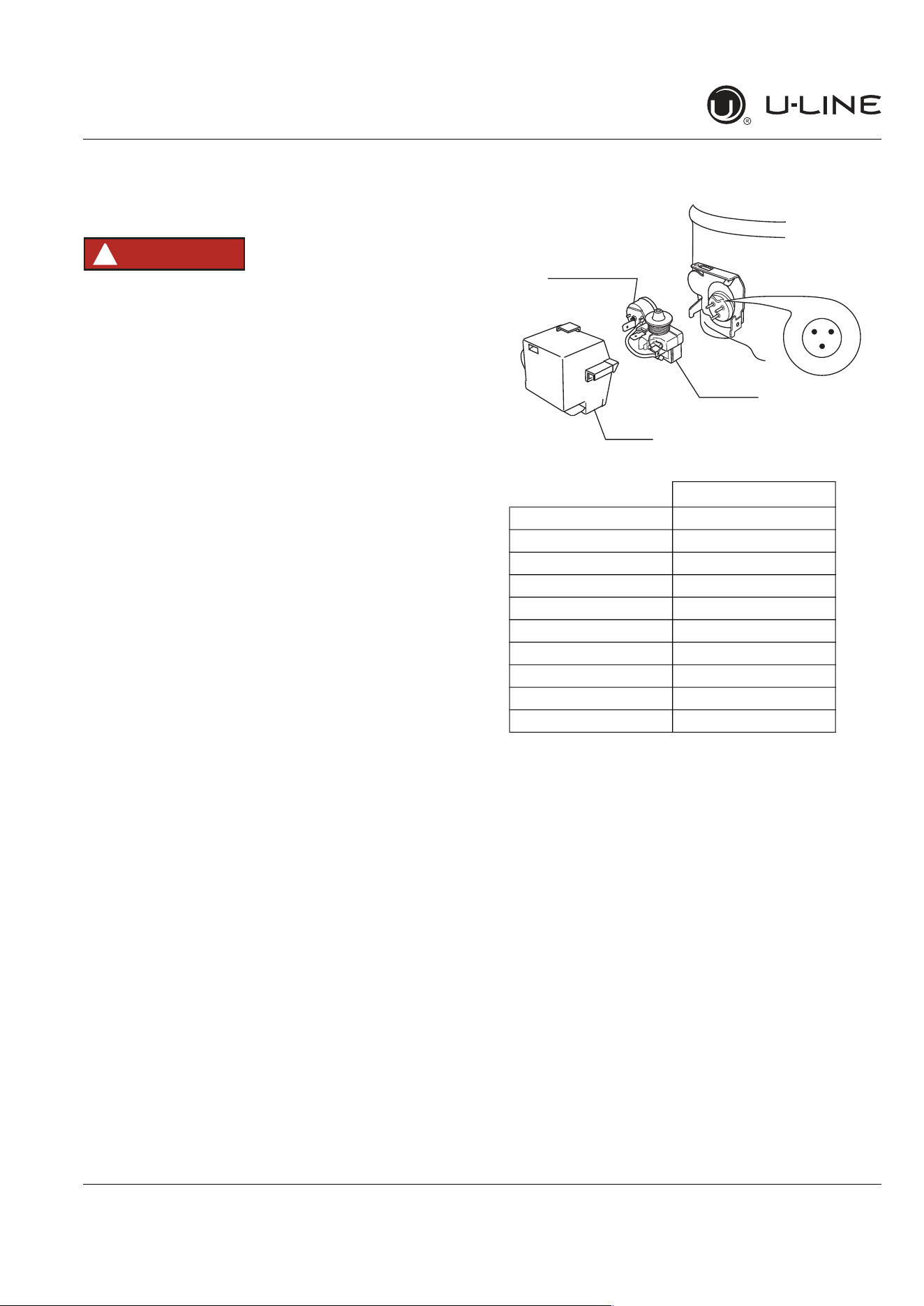
To measure the start winding resistance, measure across
the C and S pins.
To measure the run winding resistance, measure across
the C and R pins.
Also check S to R and you should get the sum of the run
and start windings.
To ensure the windings are not shorted, check the S and R
to ground.
* All resistance readings are ±10%
EM150HER
Refrigerant R134a
Voltage 115 VAC
Frequency 60 Hz
Run Cap n/a
Start Winding 12.1 Ohm at 77°F
Run Winding 3.9 Ohm at 77°F
LRA 18.0 A
FLA 2.0 A
Starting Device 213514105
Overload 4TM757KFBYY-53
ULIN_0576_AW
R S
C
OVERLOAD PROTECTOR
STARTING RELAY
RELAY COVER
32
CAUTION
!
33
34
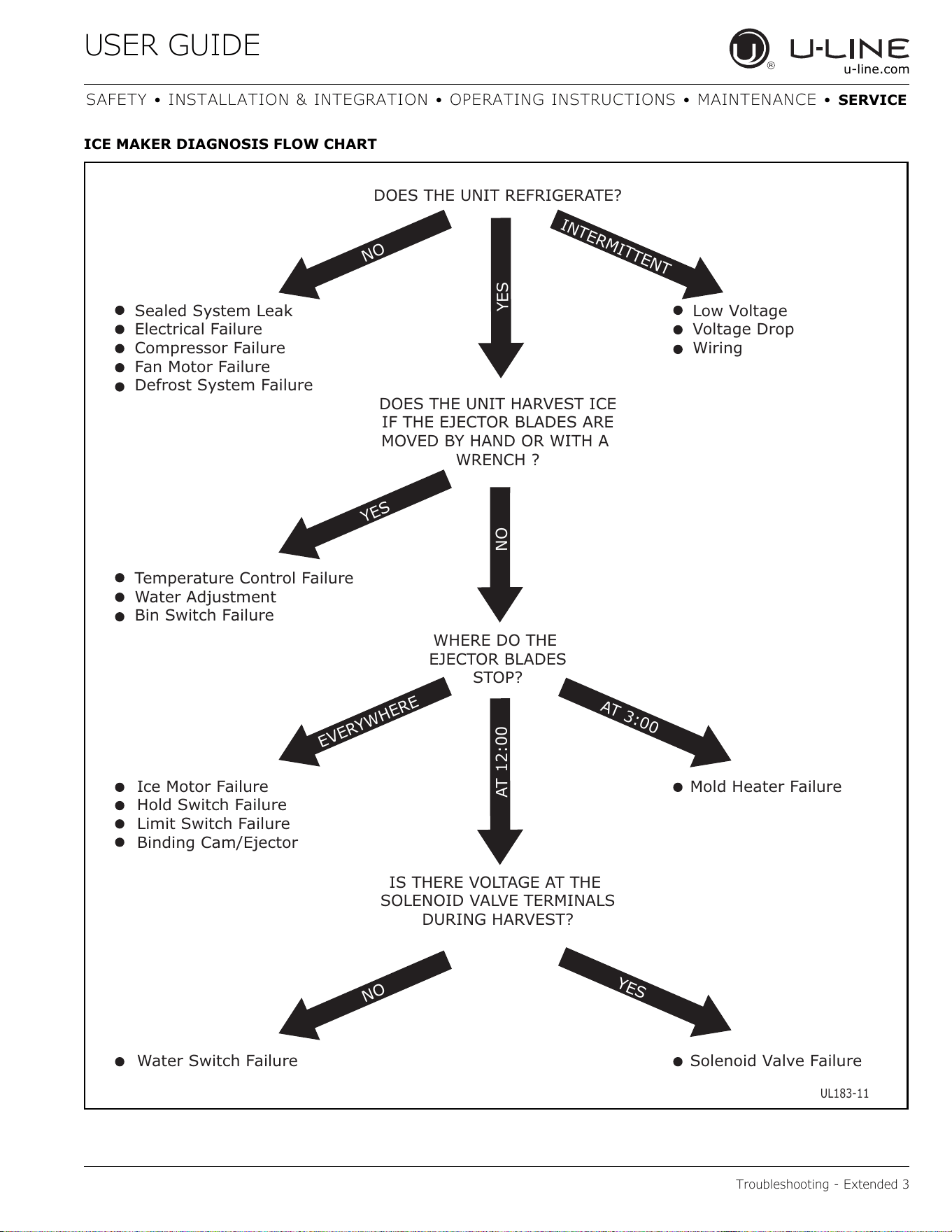
DOES THE UNIT REFRIGERATE?
Sealed System Leak
Electrical Failure
Compressor Failure
Fan Motor Failure
Defrost System Failure
Low Voltage
Voltage Drop
Wiring
Temperature Control Failure
Water Adjustment
Bin Switch Failure
NO
NO
EVERYW
H
E
RE
IN
T
E
R
M
IT
T
ENT
A
T
3:00
Y
E
S
N
O
A
T
1
2:
0
0
DOES THE UNIT HARVEST ICE
IF THE EJECTOR BLADES ARE
MOVED BY HAND OR WITH A
WRENCH ?
WHERE DO THE
EJECTOR BLADES
STOP?
Mold Heater Failure
Solenoid Valve Failure
Ice Motor Failure
Hold Switch Failure
Limit Switch Failure
Binding Cam/Ejector
Water Switch Failure
IS THERE VOLTAGE AT THE
SOLENOID VALVE TERMINALS
DURING HARVEST?
UL183-11
Y
ES
YES
35
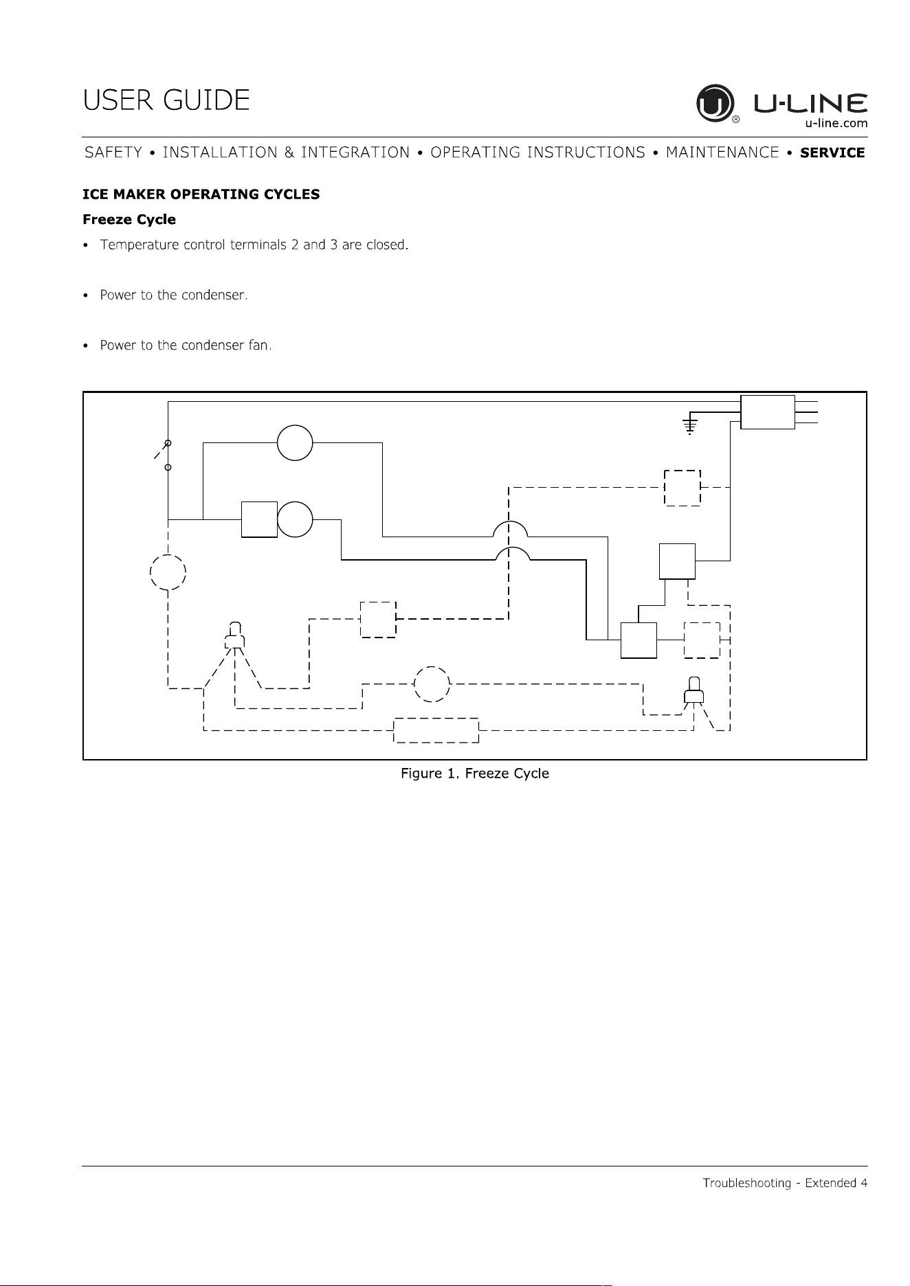
SWITCH
LIMIT
orange
black
black
black
MOTOR
MAKER
ICE
MOLD HEATER
WATER
SWITCH
FILLC
NC
MOTOR
FAN
LOAD
OVER
black
RELAY
START
COMP.
SWITCH
OFF
ON
black
black
blue
black
CONTROL
TEMP.
NC
black
orange
3
yellow
2
orange
SWITCH
BIN
red
NO
1
C
NO
brown
black
white
C
SWITCH
HOLD
VALVE
WATER
ground
UL183-4
36
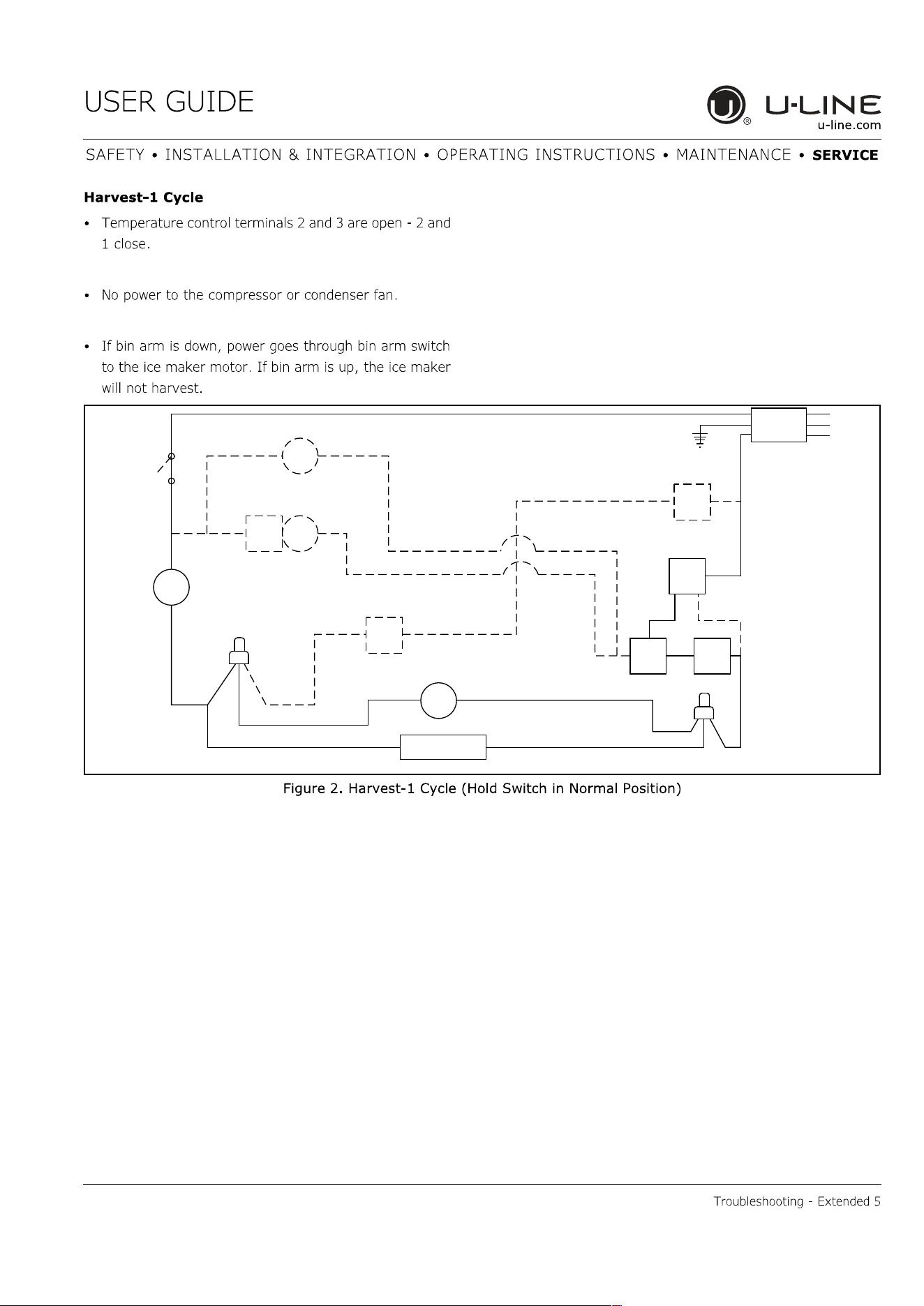
SWITCH
LIMIT
orange
black
black
black
MOTOR
MAKER
ICE
MOLD HEATER
WATER
SWITCH
FILL
C NC
MOTOR
FAN
LOAD
OVER
black
RELAY
START
COMP.
SWITCH
OFF
ON
black
black
blue
black
CONTROL
TEMP.
NC
black
orange
3
yellow
2
orange
SWITCH
BIN
red
NO
1
C
NO
brown
black
white
C
SWITCH
HOLD
VALVE
WATER
ground
UL183-5
37
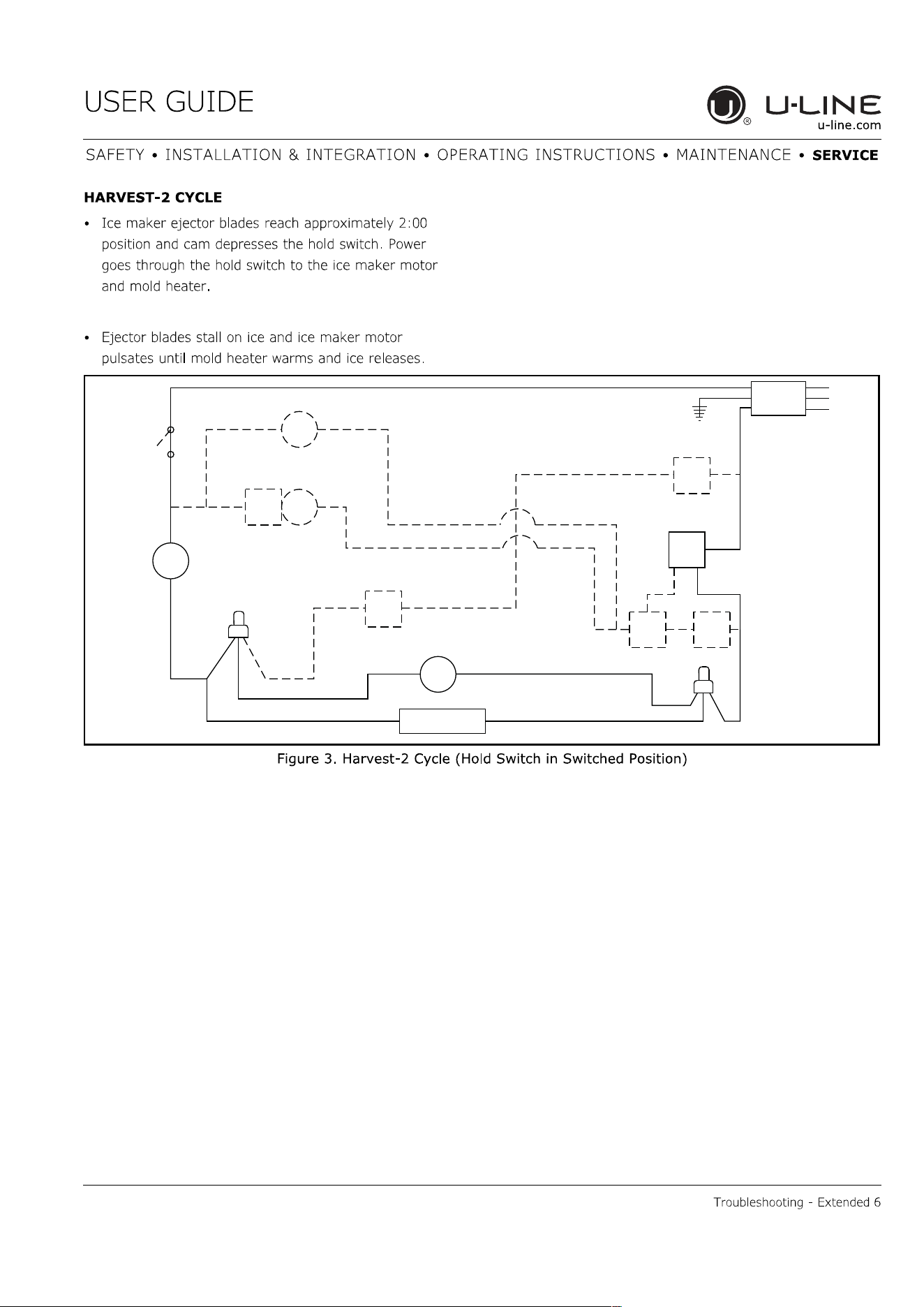
SWITCH
LIMIT
orange
black
black
black
MOTOR
MAKER
ICE
MOLD HEATER
WATER
SWITCH
FILL
C
NC
MOTOR
FAN
LOAD
OVER
black
RELAY
START
COMP.
SWITCH
OFF
ON
black
black
blue
black
CONTROL
TEMP.
NC
black
orange
3
yellow
2
orange
SWITCH
BIN
red
NO
1
C
NO
brown
black
white
C
SWITCH
HOLD
VALVE
WATER
ground
UL183-6
38
SWITCH
LIMIT
orange
black
black
black
MOTOR
MAKER
ICE
MOLD HEATER
WATER
SWITCH
FILLC
NC
MOTOR
FAN
LOAD
OVER
black
RELAY
START
COMP.
SWITCH
OFF
ON
black
black
blue
black
CONTROL
TEMP.
NC
black
orange
3
yellow
2
orange
SWITCH
BIN
red
NO
1
C
NO
brown
black
white
C
SWITCH
HOLD
VALVE
WATER
ground
UL183-7
39
YELLOW WIRE
CONNECTION
RED WIRE
CONNECTION
BLUE/BLACK WIRE
CONNECTION
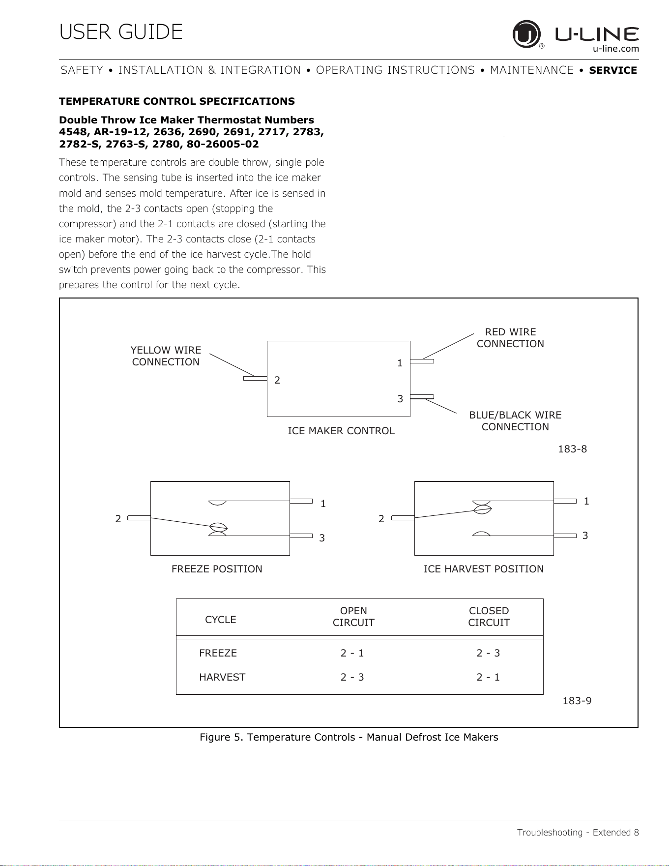
ICE MAKER CONTROL
2
1
3
183-8
2 2
1
3
1
3
FREEZE POSITION ICE HARVEST POSITION
CYCLE
CLOSED
CIRCUIT
OPEN
CIRCUIT
FREEZE 2 - 1 2 - 3
HARVEST 2 - 3 2 - 1
183-9
40
28.12
3.00
183-10
41
42
43
USER GUIDE
Defrost 1
u-line.com
SAFETY INSTALLATION & INTEGRATION OPERATING INSTRUCTIONS MAINTENANCE SERVICE
Defrost
These units are manual defrost.
To defrost unit remove ice bucket. Turn unit off. Use
toweling inside to absorb water as it melts down. This will
help prevent water from getting onto customer’s floor.
The defrost duration is dependent upon usage or climate.
Typically, defrosting is needed approximately every 3-6
weeksand/orwhen1/4"ormoreoffrostispresent-
whichevercomesfirst.
44

Copyright © 2020 U-Line Corporation. All Rights Reserved. | Publication Number 30379 | 11/2020 Rev. O
U-LineCorporation(U-Line)LimitedWarranty
OneYearLimitedWarranty
For one year from the date of original purchase, this warranty covers all parts and labor to repair or replace any part of the product that
proves to be defective in materials or workmanship. For products installed and used for normal residential use, material cosmetic defects
are included in this warranty, with coverage limited to 60 days from the date of original purchase. All service provided by U-Line under the
above warranty must be performed by a U-Line factory authorized servicer, unless otherwise specified by U-Line. Service provided during
normal business hours.
TwoYearLimitedWarranty(5ClassProduct)
For two years from the date of original purchase, this warranty covers all parts and labor to repair or replace any part of the product that
proves to be defective in materials or workmanship. For products installed and used for normal residential use, material cosmetic defects
are included in this warranty, with coverage limited to 60 days from the date of original purchase. All service provided by U-Line under the
above warranty must be performed by a U-Line factory authorized servicer, unless otherwise specified by U-Line. Service provided during
normal business hours.
AvailableSecond&ThirdYearLimitedWarranty
In addition to the standard one and two year warranties outlined above, U-Line offers a one year extension of the warranties from the date
of purchase, free of charge. To take advantage of this extension, you must register your product with U-Line within 60 days from the date
of purchase at u-line.com and provide proof of purchase.
FiveYearSealedSystemLimitedWarranty
For five years from the date of original purchase, U-Line will repair or replace the following parts, labor not included, that prove to be
defective in materials or workmanship: compressor, condenser, evaporator, drier, and all connecting tubing. All service provided by U-Line
under the above warranty must be performed by a U-Line factory authorized servicer, unless otherwise specified by U-Line. Service
provided during normal business hours.
Terms
These warranties apply only to products installed in any one of the fifty states of the United States, the District of Columbia, or the ten
provinces of Canada. The warranties do not cover any parts or labor to correct any defect caused by negligence, accident or improper use,
maintenance, installation, service, repair, acts of God, fire, flood or other natural disasters. The product must be installed, operated, and
maintained in accordance with your product’s User Guide.
The remedies described above for each warranty are the only ones that U-Line will provide, either under these warranties or under any
warranty arising by operation of law. U-Line will not be responsible for any consequential or incidental damages arising from the breach of
these warranties or any other warranty, whether express, implied, or statutory. Some states do not allow the exclusion or limitation of
incidental or consequential damages, so the above limitation or exclusion may not apply to you. These warranties give you specific legal
rights, and you may also have other rights which vary from state to state.
Any warranty that may be implied in connection with your purchase or use of the product, including any warranty of merchantability or any
warranty fit for a particular purpose is limited to the duration of these warranties, and only extends to five years in duration for the parts
described in the section related to the five year limited warranty above. Some states do not allow limitations on how long an implied warranty
lasts, so the above limitations may not apply to you.
• The warranties only apply to the original purchaser and are non-transferable.
• The second, third, and five year warranties cover products installed and used for normal residential or designated marine use only.
• The warranties apply to units operated outside only if designed for outdoor use by model and serial number.
• U-Line Commercial products are covered by the one year and 5 year limited warranties and are not eligible for the second and
third year limited warranties.
• Replacement water filters, light bulbs, and other consumable parts are not covered by these warranties.
• The start of U-Line’s obligation is limited to four years after the shipment date from U-Line.
• In-home instruction on how to use your product is not covered by these warranties.
• Food, beverage, and medicine loss are not covered by these warranties.
• If the product is located in an area where U-Line factory authorized service is not available, you may be responsible for a trip
charge or you may be required to bring the product to a U-Line factory authorized service location at your own cost and expense.
• Units purchased after use as floor displays, and/or certified reconditioned units, are covered by the limited one year warranty only
and no coverage is provided for cosmetic defects.
• Signal issues related to Wi-Fi connectivity are not covered by these warranties.
For parts and service assistance, or to find U-Line factory authorized service near you, contact U-Line:
8900 N. 55
th
Street,Milwaukee,WI53223•u-line.com•onlineservice@u-line.com•+1.414.354.0300
45