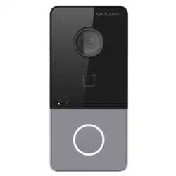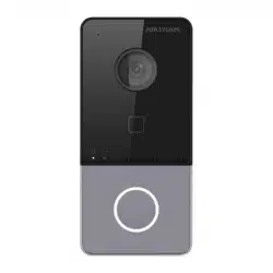

DS-KV61X3-(W)PE1(C)
Video Intercom Villa Door Sta�on
UD28151B-D
Microphone
2
Indicator
3
Bu�on
4
Card Reading Area
5
Loudspeaker
6
Terminals
7
Debugging Port
8
Note: The debugging port is used for debugging only.
Terminal and Wiring
2
Installa�on Accessory
3
ENGLISH
Diagram References
1
Appearance
Surface Moun�ng without Protec�ve Shield
1. S�ck the moun�ng template on the wall. Drill screw holes according to the moun�ng
template. Remove the template from the wall.
2. Secure the moun�ng plate on the wall with 4 supplied screws according to the screw
holes.
3. Install the villa door sta�on to the moun�ng plate. Fix the device on the moun�ng
plate with the set screw.
Make sure all related equipments are power-o during the installa�on.
Tools that you need to prepare for installa�on:
Drill (ø2.846) and gradienter.
Purchase the protec�ve shield before installa�on.
Before You Start
1. S�ck the moun�ng template on the wall. Drill the screw holes according to the
moun�ng template. Remove the template from the wall.
2. Align the protec�ve shield with the moun�ng template.
3. Secure the moun�ng plate and protec�ve shield on the wall with 4 supplied screws
according to the screw holes.
4. Install the villa door sta�on to the moun�ng plate. Fix the device on the moun�ng
plate with the set screw.
11
Congura�on via Web
5
You are required to ac�vate the device rst by se�ngs a strong password before you
can use the device.
Ac�vate Device via Web
1
Access to the Device by Web Browsers
2
1. In the browser address bar, enter the IP address of the device, and press the Enter
key to enter the login page.
2. Enter the user name and password and click Login.
Refers to Video Intercom Villa Door Sta�on User Manual (scan the QR code) for details.
1
TAMPER
9
2
3
4
5
6
7
8
9
10
11
12
Exit Button
TO EXIT
2
Orange RS-485+
Yellow RS-485-
Red 12 VDC
Black GND
White AIN1
White AIN2
White AIN3
White AIN4
Yellow NC
Green COM
Blue
NO
Black GND
Black GND
PRESS
Power
Input
Reserved
DS-KV6103-PE1(C) DS-KV6113-WPE1(C)
1
Camera
Set Screw
10
TF Card Slot
11
Network Interface
12
Indicator Descrip�on
Unlock: Green
Call: Orange Communicate: White
NC: Door Lock Relay Output (NC)
NO: Door Lock Relay Output (NO)
COM: Common Interface
AIN1: For the access of Door Contact
AIN3: For the access of Exit Bu�on
AIN2&AIN4: Reserved
485-: RS-485 Interface (Reserved)
485+: RS-485 Interface (Reserved)
12 VDC IN: Power Supply Input
GND: Grounding
Moun�ng Template
2
1
Moun�ng Plate
Note: The dimension of the moun�ng plate is 102.58 mm × 39.24 mm × 6.2 mm.
Installa�on
4
Note: Video intercom villa door sta�on supports surface moun�ng.
Default parameters of door sta�on are as follows:
Default IP Address: 192.0.0.65.
Default Port No.:8000.
Default User Name: admin
1. Power on the device, and connect the device to the network.
2. Enter the IP address into the address bar of the web browser, and click Enter to enter
the ac�va�on page.
Note: The computer and the device should belongs to the same subnet.
3. Create and enter a password into the password eld.
4. Conrm the password.
5. Click OK to ac�vate the device.
Note: When the device is not ac�vated, the basic opera�on and remote congura�on of device cannot be
performed.
Communicate with Indoor Sta�on
3
1. Click Se�ngs -> Intercom -> Press Bu�on to Call to enter the se�ngs page.
2. Set the parameters.
- Edit call No. for every bu�on.
- Check Call Management Center to set the bu�on calling center.
Note: If you check Call Management Center and set the call No. as well, call management center has
higher privilege than call No.
3. Press bu�on to call indoor sta�on.
4
Issue Card
1. Click Se�ngs -> Access Control and Elevator Control to enter the se�ngs page.
2. Click Issue Card. Present the card on the card reading area.
3. When issuing nished, the windows pop up on the se�ngs page.
Note:
Only M1 card supported, and Mifare card with non-standard shape is recommended.
Up to 10000 cards can be issued and managed by V series door sta�on. A voice prompt (No more cards
can be issued.) can be heard when the issued card amount exceeds the upper limit.
5
Unlock Door
A�er issuing cards, you can unlock the door by presen�ng the issued cards.
4
2
1
3
Screws
Villa Door Station
Mounting Plate Mounting Template Wall
1
3
4
2
Screws
Screws
Villa Door Station
Mounting Plate Protective Shield Mounting Template Wall
Surface Moun�ng without Protec�ve Shield
Surface Moun�ng with Protec�ve Shield
3
Vertical: 75°
Horizontal: 129°
Highest Height: 1.78 m
Lowest Height: 1.02 m
0.5 m
0.5 m
1.4 m
Vertical: 75°
Vertical: 75°
Highest Height: 1.88 m
Highest Height: 1.98 m
Lowest Height: 1.12 m
Lowest Height: 1.22 m
0.5 m0.5 m
1.6 m
1.5 m
Recommended Installation Height (The distance between the camera and the
ground): 1.4 m to 1.6 m.
The re commen ded dist ance fr om the g round l evel is 1.40
adjus table d epends o n the he ight of body.
102023104
Hole1
Hole2
Hole1
Hole1 Hole1
102.58
1.18
Unit : mm
6.2
39.24
3.45
1
2
5
Ap ply
Si licone
Se alant
A
B
Surface Moun�ng with Protec�ve Shield
Note: Apply silicone sealant among the cable wiring area to keep the raindrop from entering. Please refer
to figure A.
Note: If installing outdoors, you are advised to install the device with protective shield. For the finished
view, please refer to figure B.
Remarque : l’apparence de l’
appareil varie selon le modèle. Reporte
z-vous à l’appareil pr
oprement dit.
Descrip�on de l’indicateur
Déverrouillage : Vert
Borne et câblage
Remarque : report
ez-vous au manuel d’u�lisa�on pour une descrip�on du câblage.
Accessoire d’installa�on
Remarque : pour connaître les dimensions des accessoires d’installa�on, veuille
z vous report
er au manuel
d’u�lisa�on.
Installa�on
Avant de c
ommencer
● Assure
z-vous que l’appareil dans son emballage es
t en bonne condi�on et que toutes
les pièces de montage sont incluses.
● Assur
ez-vous que tous les équipements connex
es sont hors tension pendant
l’installa�on.
● Vériez que les spécica
�ons du produit sont adéquates à l’environnemen
t
d’installa
�on.
R
emarque : pour l’installa�on, reportez-vous à la gure et au manuel d’u�lisa�on.
Congura�on
Ac�ver un appareil
Vous devr
e
z d’
abord ac�ver l’
appareil en dénissant un mot de passe f
ort a
v
ant de
pouvoir l’u�liser
.
Ac�v
e
z l’
appareil à dist
ance via le logiciel clien
t iVMS-4200.
Congura�on à dis
tance
Remar
que : Pour plus de détails sur la congura�on, consultez le manuel d’u�lisa�on.
Microphone
Indicat
eur
Touche
Zone de lecture de cart
e
Haut-parleur
Bornes P
ort de débogag
e
Appar
ence
SABOTAGE
Caméra
Vis de blocag
e
F
ente de carte TF
Interface réseau
Appeler : orange
Communiquer : blanc
FRANÇAIS
Références du schéma
ENGLISH
Diagram References
ENGLISH
Diagram References
ENGLISH
Diagram References
ENGLISH
Diagram References
ENGLISH
Diagram References
ENGLISH
Diagram References
ENGLISH
Diagram References
ENGLISH
Diagram References
ENGLISH
Diagram References
ENGLISH
Diagram References
ENGLISH
Diagram References
ENGLISH
Diagram References
ENGLISH
Diagram References
ENGLISH
Diagram References
Hinweis: Der Au�au des Geräts variiert je nach Modell. Beziehen Sie sich auf das tatsächliche Gerät.
Anzeigen
Entriegeln: Grün
Anschlüsse und Verkabelung
Hinweis: Die Beschreibung der Verkabelung nden Sie im Benutzerhandbuch.
Installa�onszubehör
Hinweis: Entnehmen Sie den Umfang des Inst
alla�onszubehörs dem Benutzerhandbuch.
Ins
talla�on
Bevor Sie beginnen
● Acht
en Sie darauf, dass sich das Gerät in der V
erpackung in gutem Zustand be
ndet und
alle Mont
ageteile enthalten sind.
●
Acht
en Sie dara
uf, d
ass
alle relev
anten
Geräte
während
der Monta
ge ausg
eschal
tet si
n
d
.
● Überprüfen Sie die Produktspe
zika�on für die Installa�onsumgebung.
Hinweis: Einzelheiten zur Ins
talla�on nden Sie in der Abbildung und im Benutzerhandbuch.
Kon
gura�on
Gerä
t ak�vieren
Bevor Sie das Gerät benutzen können, müssen Sie zunächst ein sicher
es Passwort
fes
tlegen, um das Gerät zu ak�vieren.
Ak�vierung aus der Ferne über das W
eb oder die iVMS-4200 Client-So�ware.
Fernk
ongura�on
Hinweis: Weitere Inf
orma�onen zur Kongura�on nden Sie im Benutzerhandbuch.
Mikr
ofon
Statusanzeige
Tast
e
Kartenlesebereich Lautsprecher
Anschlussklemmen Debug-Anschluss
Au�au
SABOT
AGE
Kamer
a
Feststellschr
aube
TF-Kartensteckplatz
Netzwerk
anschluss
Anruf: Orange
Kommunika�on: Weiß
DEUTSCH
Verweise auf Schaubilder
Nota: el aspecto del disposi�vo varía en función del modelo. Remítase al disposi�vo en cues
�ón.
Descripción del indicador
Desbloquear: Verde
Terminal y cableado
Nota: Para v
er una descripción del cableado, consulte el manual de usuario.
Accesorio de instalación
Nota: consulte el manual de usuario par
a ver las dimensiones de los accesorios de instalación.
Instalación
Ant
es de comenzar
● Asegúrese de que el disposi�vo incluido es
té en buenas condiciones y se incluyan todas
las piezas de ensamblaje.
●Asegúrese de que todos los equipos relacionados estén apag
ados durante la ins
talación.
● Consulte las especic
aciones del producto al realizar la inst
alación.
Nota: Not
a: consulte las ilustraciones y el manual de usuario par
a conocer el procedimiento de instalación.
Con
guración
Ac�v
ar disposi�vo
Ant
es de poder u�lizar el disposi�vo es necesario ac�varlo estableciendo una
c
ontraseña segura.
Ac�v
elo a distancia a través de la página web o el so�ware de client
e iVMS-4200.
Congur
ación remota
Not
a: consulte el manual de usuario para ver la conguración.
Micrófono
Piloto
Bot
ón
Ár
ea de lectura de tarjetas
Altavoz
Terminales Puerto de depuración
Apariencia
MANIPULACIÓN
Cámara
Tornillo de presión
Ranura para t
arjeta TF
Int
erf
az de r
ed
Llamar: naranja
Comunicar: blanco
ESPAÑOL
Referencias del diagrama
Nota: l'aspe�o del disposi�vo varia in base al modello. Fare riferimento al disposi�vo e
e�vo.
Descrizione degli indicatori
Sblocco: Verde
Terminale e cablaggio
Nota: la descrizione del cablaggio fa rif
erimento al Manuale dell'utente.
Accessori per l’installazione
Nota: Per le dimensioni degli accessori di inst
allazione, consultare il Manuale dell'utente.
Installazione
Prima di iniziare
● V
ericare il disposi�vo con
tenuto nella confezione sia in buone condizioni e che tu� gli
elemen� di assemblag
gio siano presen�.
● Veric
are che duran
te l'ins
t
allazione tu�e apparecchia
tur
e correlate siano spent
e.
● Controllar
e che le speciche del prodo�o corrispondano a quelle dell'ambiente di
installazione.
Nota: Per l'inst
allazione, fare rif
erimento alla gura e al Manuale dell'utente.
Congurazione
A�va disposi�vo
Prima di u�lizzare il disposi�v
o è necessario a�varlo impostando una password sicura.
A�vazione r
emota via Web o tr
amite il so�ware client iVMS-4200.
Congurazione remota
Nota: P
er la congur
azione, consult
are il Manuale dell'utente.
Micr
ofono
Indica
tore
Pulsante
Area di le�ur
a schede
Altoparlante
T
erminali
Porta di debug
ging
Aspe�o
MANOMISSIONE
Telec
amera
Vite di arresto Slot per scheda TF
Interfaccia di rete
Chiamata: arancione
Comunicazione: bianco
ITALIANO
Riferimento schemi
Not
a: O aspeto do disposi�vo varia consoante o modelo. Consulte o pr
óprio disposi�vo.
Descrição do indic
ador
Desbloqueado: V
erde
Terminal e c
ablagem
Nota: P
ara obter a descrição da ação, consulte o Manual de U�lizador.
Acessório para ins
talação
Nota: Par
a obter a dimensão dos acessórios para instalação, consulte o Manual do U�liz
ador.
Inst
alação
Antes de começar
● Cer�que-se de que o disposi�vo na embalagem se encontra em boas c
ondições e de
que todas as peças de mon
tagem estão incluídas.
● Cer�que-se de que, durante a inst
alação, todo o equipamento relacionado se
encontr
a deslig
ado.
● Verique a especicaç
ão do produto par
a o ambient
e de ins
talaç
ão.
Nota: Par
a a instalação, consulte a gura e o Manual do U�lizador.
Con
guração
A�v
ar disposi�vo
Ant
es de poder u�liz
ar o disposi�v
o, é necessário a�vá-lo primeiro
, denindo uma
pala
vra-passe segura.
A
�ve o disposi�vo remotamente atr
avés da Web ou do so�ware iVMS-4200 do cliente.
Congur
ação remot
a
Not
a: Para obter informações sobre a conguração r
emota, consulte o Manual do U�lizador.
Microf
one
Indicador
Botão
Ár
ea de leitura de cartões
Al�falan
te
T
erminais
Porta de depuração
Aspeto
ADULTERAÇÃ
O
Câmara
Parafuso de xação Ranhura Para Cartão TF
Interface de rede
Chamada: Cor de laranja
Comunicar: Branco
PORTUGUÊS
Referências do diagrama
Opmerking: De ver
schijningsvorm van het apparaat kan v
ariëren naar gelang de verschillende modellen.
V
erwijst naar het daadwerkelijke appar
aat.
Indica
torbeschrijving
Ontgrendelen: Groen
Bellen: Oranje
Aanslui�ngen en bedr
ading
Opmerking: De omschrijving van de bedrading v
erwijst naar de gebruiksaanwijzing.
Installa
�e-accessoire
Opmerking: Raadpleeg de gebruiker
shandleiding voor de afme�ngen van installa�e-accessoires.
Installa�e
Voordat u begint
● Zorg da
t het verpakt
e appar
aat zich in goede staa
t bevindt en er geen onderdelen
ontbreken.
● Zorg dat alle bijbehor
ende apparatuur �jdens de inst
alla�e is uitgeschakeld.
● Controleer de productspecica
�e op geschiktheid in de installa�eomgeving.
Opmerking: Raadpleeg voor installa�e de a�eeldingen en de gebruikershandleiding.
Con
gura�e
Apparaat ac�veren
U dien
t het apparaat voor gebruik eers
t te ac�veren door er een s
terk w
ach
twoord voor
in t
e stellen.
Ac�v
eer op afstand via int
ernet of iVMS-4200-clientso�ware.
Congur
a�e op afstand
Opmerking: Raadpleeg de gebruiker
shandleiding voor de congura�e.
Micr
ofoon
Pictogram
T
oets
Kaartleesgedeelte Luidspreker
Aanslui�ngen
Poort voor debugg
en
Uiterlijk
MANIPULATIE
Camera
St
elschroef
Sleuf TF-kaart
Netwerkinterface
Communiceren: Wit
NEDERLANDS
Schemareferen�es
Po
známka: Vzhled zařízení se u různých modelů liší. Viz konkrétní zařízení.
Popis indikát
oru
Odemknout: Zelená
Sv
orka a zapojení
Poznámka: Popis z
apojení viz uživatelská příručk
a.
Příslušenství pro inst
alaci
Poznámka: R
ozměry příslušenství pro instalaci naleznete v uživatelské příručce.
Montáž
Dříve ne
ž začnete
●
Ujistět
e se, zda je zařízení v balení v dobrém stavu a zda jsou přít
omny všechny
dodáv
ané součás�.
● Ujistět
e se, že veškerá příslušná zaříz
ení jsou během instalace vypnutá.
● Zkontrolujt
e technické údaje produktu týkající se prostředí instalace.
Poznámk
a: Při instalaci se řiďte obrázkem a uživatelskou příručk
ou.
Kongurace
Ak�vace zařízení
Před použi�m zařízení je musíte ak�v
ovat nastav
ením silného hesla.
Zaří
z
e
ní se a
k�vu
je vz
dáleně n
a webu
neb
o prostře
dnict
vím k
lientské
ho so�waru
iVMS
-4200.
Vzdálená kongur
ace
Poznámka: Konguraci naleznete v uživatelské příručce.
Mikrofon
Indikátor
Tlačítko
Oblast čtení karty
R
eproduktor
Svorky Ladicí port
Vzhled
NEOPRÁVNĚNÉ MANIPULACE
Kamera
St
avěcí šroub
Slot pro k
artu TF
Síťové rozhr
aní
Volání: Oranžová Komunikace: Bílá
ČEŠTINA
Popis obrázků
Bemærk: Enhedens udseende kan v
ariere a�ængig
t af model. Der henvises �l den fak�ske enhed.
Beskriv
else af kontrollampe
Lås op: Grøn
T
erminal og ledningsføring
Bemærk: F
or beskrivelse af kabelføring henvises �l brugervejledningen.
Installa�ons�lbehør
Bemærk: Find målene for ins
talla�ons
�lbehør i brugerv
ejledningen.
Installa
�on
Før du s
tarter
● Kon
trollér, at enheden i pakken er i god �lst
and, og at alle dele �l samling medfølger.
● Kontrollér, at alt �lkny�
et udstyr er slukket under inst
alla�onen.
● Kontrollér produktspecik
a�onerne for installa�onsmiljøet.
Bemærk: Find oplysninger om installa�onen i guren og brugervejledningen.
Kongura�on
Ak�vér enhed
Du skal først ak�vere enheden ved at inds�lle en stærk adgangsk
ode, før du k
an anv
ende
enheden.
Ak�vér via �ernbetjening på ne�et eller via iVMS-4200-klientso�ware.
Fjernbetjent kongura�on
Bemærk: Find oplysninger om kongura�on i brugervejledningen.
Mikrofon
Kontrollampe
Knap
Område �l kortlæsning
Høj�aler
Terminaler
Port �l fejlnding
Beskriv
else
MANIPULATION
Kamera
Fastspændingsbolt
TF-kortplads
Netværkss�k
Opkald: Orange
Kommunikér: Hvid
DANSK
Diagramoversigt
ENGLISH
Diagram References
ENGLISH
Diagram References
Megjegyzés: Az eszkö
z megjelenése a különböző modellektől függően változik. Lásd az aktuális eszkö
zt.
Jelzés leírása
Nyitás: Zöld
Csatlakozó és veze
tékek
Megjegyzés: A huzalozás leírása a használa� útmut
atóban leírtakra hivatko
zik.
Szerelési eszköz
Megjegyzés: A szerelési eszk
özök méretét a felhasználói útmutatóban t
alálja.
Telepít
és
A kezdés elő�
●
Győződjön meg arról, hogy a csomagban t
alálható eszk
öz kifogást
alan állapotú,
és egyetlen sz
erelési tarto
zék sem hiányzik.
● Biz
onyosodjon meg arról, hogy minden kapcsolódó eszközt ár
amtalaníto� a f
elszerelés
ideje ala�.
● A telepítési k
örnyezetre vona
tkozóan ellenőrizz
e a termék műszaki adatait.
Megjegyzés: A telepítéssel k
apcsolatban lásd az ábrát, illetve a felhasználói útmutatót.
Kongurálás
Eszköz ak�válása
Az eszköz használata elő� egy erős jels
zó beállításával ak�válnia kell az eszk
özt.
Távoli ak�válás a w
eben vagy iVMS-4200 kliensszo�veren keres
ztül.
Távoli kongurálás
Megjegyz
és: A kongurálással k
apcsolatos tudnivalókat a felhasználói útmutatóban találja.
Mikrofon
Jelző
Gomb
Kártyaolvasó terület Hangs
z
ór
ó
Csatlak
ozók
Hibakereső port
Külső megjelenés
SZABO
TÁZSKAPCSOL
Ó
Kamera
Állítócsavar
TF- (SD-) kárty
an
yílás
Hálóz
a� csatlak
o
z
ó
Hívás: Narancs
Kommunikáció: Fehér
MAGYAR
Az ábra jelölései
ENGLISH
Diagram References
ENGLISH
Diagram References
ENGLISH
Diagram References
ENGLISH
Diagram References
ENGLISH
Diagram References
ENGLISH
Diagram References
ENGLISH
Diagram References
ENGLISH
Diagram References
ENGLISH
Diagram References
ENGLISH
Diagram References
ENGLISH
Diagram References
ENGLISH
Diagram References
ENGLISH
Diagram References
ENGLISH
Diagram References
Uwag
a: W
y
gląd urządzenia jest zależny od modelu. Skorzys
taj ze specykacji danego urządzenia.
Opis wskaźnik
ów
Odblokowanie: zielony
Złącza i połącz
enia
Uwaga: Opis połącz
eń jest dostępny w podręczniku użytkownika.
Ak
cesoria instalacyjne
Uwaga: Aby uzysk
ać informacje dotyczące wymiarów akcesoriów inst
alacyjnych, sk
orzystaj z podręcznika
użytkownika.
Instalacja
Z
anim ro
zpoczniesz
● Upewnij się, że urządzenie w pakiecie nie jest uszkodzone i dostarcz
ono wszys
tkie
elementy mon
tażowe.
● Upewnij się, że zasilanie powiązanego wyposaż
enia jest wyłączone podczas instalacji.
● Sprawdź specykacje produktu dotyczące warunków otocz
enia w miejscu instalacji.
Uw
aga: Aby uzysk
ać informacje dotyczące instalacji, skorzys
taj z rysunku w podręczniku użytkownika.
Konguracja
Aktywuj urządzenie
Przed użyciem urządzenia należy je aktywować, ust
awiając silne hasło dla urządzenia.
Aktywuj urządzenie zdalnie przy użyciu przeglądarki int
ernetowej lub oprogramow
ania
klienckiego iVMS-4200.
Konguracja zdalna
Uwaga: Aby uzyskać informacje dotyczące kongur
acji, skorzystaj z podr
ęcznika użytkownik
a.
Mikrofon
Wskaźnik
Prz
y
cisk
Czytnik kart Głośnik
Złącze
Złącze do debugowania
Elemen
ty urządzenia
Zab
ezpiecz
enie antys
abo
tażo
we
Kamera
Śruba ustalając
a
Gniazdo karty TF Złącze sieciowe
Połączenie: pomarańczowy
Komunikacja: biały
POLSKI
Opis diagramu
Notă: Aspectul dispozi�vului variază în funcţie de diferit
e modele. Se referă la dispozi�vul actual.
Descriere indicator
Deblocare: Verde
Terminal şi cablare
Notă: Descrierea cablării face ref
erire la manualul de u�lizare.
Accesoriu pentru ins
talare
Notă: Pentru dimensiunile accesoriilor de inst
alare, vă rugăm să consultaţi manualul de u�liz
are.
Instalarea
Înainte sa incepeţi
● Asigura
ţi-vă că dispozi�vul din pachet este în st
are bună şi că toate piesele pentru
asamblare sunt incluse.
● Asigura
ţi-vă că toat
e echipamentele aferen
te sunt oprite în �mpul ins
talării.
● Veric
aţi specicaţiile produsului pentru mediul de instalar
e.
Notă: Pentru ins
talare, consultaţi gura şi manualul de u�lizar
e.
Congurare
Ac�varea dispozi�vului
Pentru a put
ea u�liza dispozi�vul, trebuie mai întâi să ac�v
aţi dispozi�vul setând o parolă
puternic
ă.
Ac�vaţi de la dis
tanţă prin web sau so�ware-ul client iVMS-4200.
Congurare la dist
anţă
Notă: Pentru congurar
e, consultaţi manualul de u�lizare.
Microfon
Indica
tor
Buton
Zonă ci�r
e card
Difuzor
Terminale
Port de corectare a er
orilor
Aspect
FUR
T
Cameră
Şurub de xare Slot Card TF
Interfaţ
ă de reţ
ea
Apelare: Portocaliu
Comunicare: Alb
ROMÂNĂ
Referinţe diagramă
Poznámk
a: Vzhľad zariadenia sa líši v závislos� od modelu. Porovnajte so skutočn
ým zariadením.
P
opis kontrolky
Otv
orenie: Zelená
T
erminál a kabeláž
P
oznámka: Popis kabeláže nájdete v používateľskej príručke.
Inš
talačné príslušenstvo
P
o
známk
a: Rozmery inštalačného príslušenstva nájdete v používateľskej príručk
e.
Montáž
Pred spustením
● Uis�te sa, že z
ariadenie v balení je v dobrom stav
e a všetky montážne čas� sú súčasťou
balenia.
● Počas inštalácie sa uis�te, ž
e sú všetky súvisiace zariadenia vypnuté.
● Naštudujte si špecik
áciu výrobku a vhodné prostredie inštalácie.
Poznámka: Informácie o spr
á
vnej inštalácii nájdete na obrázku a v používateľskej príručk
e.
Kon
gurácia
Ak�vácia z
ariadenia
Pred použi�m z
ariadenia ho musíte najskôr ak�v
ov
a
ť nastav
ením silného hesla.
Z
ariad
enie a
k�v
ujte na
diaľ
ku p
rostredn
íctvom
webu
ale
bo
klie
ntskeho
so�véru
iVMS
-4200.
K
ongurácia na diaľku
P
oznámka: Informácie o kongurácii nájdete v používateľskej príručke.
Mikrofón
Indikátor
Tlačidlo
Miesto čítania kariet
Reprodukt
or
Svorky
Ladiaci port
Vzhľad
SNÍMAČ MANIPULÁCIE
Kamera
Nast
avovacia skrutka
Zásuvka na kartu TF
Sieťové ro
zhranie
Hovor: Oranžová
Komunikácia: Biela
SLOVENČINA
Referenčné schémy
Cat
atan: Tampilan perangkat beragam t
ergantung model. Silakan merujuk ke perangkat yang sebenarnya.
Deskripsi Indikat
or
Buka: Hijau
Terminal dan Perkabelan
Catat
an: Untuk deskripsi perkabelan, silakan merujuk ke Manual Pengguna.
Ak
sesori Pemasangan
Catat
an: Untuk dimensi aksesori pemasang
an, silak
an merujuk ke Manual Pengguna.
Pemasangan
Sebelum Anda Memulai
●
Pas�kan perangkat dalam kemasan kondisin
ya bagus dan semua bagian-bagiannya
disertakan.
● Pas�kan semua perala
tan yang terk
ait dinonak��an selama pemasangan.
● Periksa spesik
asi produk terhadap lingkungan pemasangan.
Catatan: Untuk cara pemasangan, silakan merujuk k
e gambar dan Manual Pengguna.
Kongurasi
Ak��an P
erangkat
P
ertama Anda harus mengak��an perangka
t deng
an membua
t kata sandi y
ang kuat
sebelum perangkat dapa
t digunakan.
Ak��an dari jarak jauh melalui w
eb at
au perangk
at lunak klien iVMS-4200.
Kongurasi Jar
ak Jauh
Cat
atan: Untuk kongur
asi, silakan merujuk ke Manual Pengguna.
Mikrofon
Indikat
or
Tombol
Area Baca K
artu
Pengeras Suar
a
Terminal
Port Debug
ging
Tampilan
PERUSAKAN
Kamera
Sekrup Setelan
Slot Kartu TF
An
tarmuka Jaringan
Panggilan: Oranye
Komunikasi: Pu�h
BAHASA INDONESIA
Referensi Diagram
Not: Cihazın görünümü farklı modellere göre değişiklik gösterir. Asıl cihaza bakın.
Gösterge Açıklaması
Kilidini aç: Yeşil
Terminal ve Kablolama
Not: Kablo bağlan� açıklaması için Kullanım Kılavuzuna bakın.
Kurulum Aksesuarı
Not: Kurulum aksesuarlarının boyutları için lü�en Kullanım Kılavuzuna bakın.
Kurulum
Başlamadan Önce
● Pake�
eki cihazın iyi durumda olduğundan ve tüm montaj parçalarının bulunduğundan
emin olun.
● Kurulum esnasında ilgili tüm ekipmanların kapalı olduğundan emin olun.
● Kurulum ortamı için ürün teknik özelliklerini kon
tr
ol edin.
Not: Kurulum için şekle ve Kullanım Kılavuzuna bakın.
Yapılandırma
Cihazı Etkinleş�r
Ciha
z
ı
kull
anabilm
eniz içi
n önce
güçlü
bir p
arola
ayarl
ay
arak
cihazı
etki
nleş�rme
niz gerek
ir.
Web veya iVMS-4200 istemci yazılımı ile uzakt
an etkinleş�rin.
Uzaktan Y
apılandırma
Not: Yapılandırma için lü�en K
ullanım K
ıla
vuzuna bakın.
Mikrofon
Gösterg
e
Düğme
Kart Okuma Alanı
Hoparlör
Terminaller
Hata A
yıklama Portu
Görünüm
KUR
CALAMA
Kamera
A
yar Vidası
TF Kart Yuvası
Ağ Arayüzü
Çağrı: Turuncu
İle�şim: Beyaz
TÜRKÇE
Şema Referansları
Примечание. Внешний вид устройства может от
личаться в зависимости от модели. См. фактическое
устройство.
Описание индикатора
Открытие: зеленый
Терминал и схема соединения
Примечание. Описание электрических подключений см. в руково
дстве пользователя.
Вспомогате
льные инструменты для установки
Примечание. Размеры вспомогательных инструментов для установки см. в руководстве пользователя.
Установка
Перед началом работы
● Убе
дитесь, что устройство в упак
овк
е находится в исправном сост
оянии, и все
составляющие комплекта поставки имеют
ся в наличии.
● Убедитесь, что во время установки все сопутствующее оборудование отключено.
● Изучите технические требования к установке устройства.
Примечание. Для получения информации об установке см. рисунки и руководство пользовате
ля.
Конфигурация
Активировать устройство
Пере
д использованием устройства необходимо сначала ег
о активировать и
установить наде
жный паро
ль.
Активируйт
е удаленно через сеть Интернет или с помощью клиент
ского
программного обеспечения iVMS-4200.
У
даленная настройка
Примечание. Све
дения о настройке см. в руково
дстве пользовате
ля.
Микрофон
Индикатор
Кнопка
Область считывателя к
арты
Динамик
Разъемы
Порт отладки
Внешний вид
ВЗЛОМ
Камера
У
становочный винт
Слот для карты TF
сетевой интерфейс
Вызов: оранжевый
Связь: белый
РУССКИЙ
Пояснения к рисункам
မွတ္ခ်က္- ကိရိယာအသြင္အျပင္သည္ ေမာ္ဒယ္အမ်ိဳးအစားေပၚမူတည္ျပီးကြဲျပားသည္။ ပကတိကိရိယာကို ၾကည့္႐ႈပါ။
အညႊန္းေဖာ္ျပခ်က္
ေသာ့ဖြင့္ရန္ - အစိမ္းေရာင္
တာမီနယ္ႏွင့္ ၀ါယာသြယ္တန္းမႈ
မွတ္ခ်က္- ေဖာ္ျပခ်က္မ်ားအတြက္ အသုံးျပဳသူလမ္းညြန္ကို ဖတ္႐ႈပါ။
အပိုပစၥည္း တပ္ဆင္ျခင္း
မွတ္ခ်က္- အပိုပစၥည္း တပ္ဆင္ျခင္း အတိုင္းအတာအတြက္ ေက်းဇူးျပဳ၍ သံုးစြဲသူ လက္စြဲကို ကိုးကားပါ။
တပ္ဆင္ျခင္း
မစတင္မီ
● အထုပ္သည္ အေျခအေန ေကာင္းေသာ အေနအထားတြင္ ရွိၿပီး တပ္ဆင္ရမည့္ အစိတ္အပိုင္း အားလံုး
ပါ၀င္သည္။
● တပ္ဆင္စဥ္အတြင္း သက္ဆိုင္ရာ ကိရိယာမ်ားအားလံုးကို ေသခ်ာစြာ ပါ၀ါ ပိတ္ထားပါ။
● တပ္ဆင္မႈ ပတ္၀န္းက်င္အတြက္ ထုတ္ကုန္ သတ္မွတ္ေဖာ္ျပခ်က္မ်ားကို စစ္ေဆးပါ။
မွတ္ခ်က္- တပ္ဆင္ျခင္းအတြက္ ကိန္းဂဏန္းမ်ားႏွင့္ သံုးစြဲသူ လက္စြဲကို ကိုးကားပါ။
ပံုစံခ်ျခင္း
ကိရိယာကို စတင္ပါ
သင္သည္ ကိရိယာကို အသံုးမျပဳႏိုင္ေသးမီ အားေကာင္းခိုင္မာေသာ စကား၀ွက္ကို ထည့္သြင္းျခင္းျဖင့္ ကိရိယာကို
စတင္အသက္သြင္းရန္ လိုအပ္သည္။
၀က္ဘ္ဆိုဒ္မွ သို႔မဟုတ္ iVMS-4200 သံုးစြဲသူ ေဆာ့ဖ္၀ဲမွ တဆင့္ အသက္သြင္းစတင္ပါ။
အေ၀းထိန္း ကိန္းဂဏန္းမ်ား
မွတ္ခ်က္- ကိန္းဂဏန္းမ်ားအတြက္ ေက်းဇူးျပဳ၍ သံုးစြဲသူ လက္စြဲကို ကိုးကားပါ။
မိုက္က႐ိုဖုန္း
အခ်က္ျပမီး
ခလုတ္
ကဒ္ ဖတ္သည့္ ဧရိယာ စပီကာ
တာမီနယ္မ်ား
အမွားရွာေဖြဖယ္ရွားျခင္း လိုင္းေပါက္
ပုံသ႑ာန္
ေျပာင္းလဲမႈ အကာအကြယ္
ကင္မရာ
ဆက္တင္ ၀က္အူ
TF ကတ္ေပါက္
ကြန္ရက္ အင္တာေဖ့စ္
ေခၚဆိုရန္ - လိေမၼာ္ေရာင္ ဆက္သြယ္ရန္ - အျဖဴေရာင္
ျမန္မာ
ပံုအညြန္း
©2020 Hangzhou Hikvision Digital Technology Co., Ltd. Tous droits réservés.
À propos de ce manuel
Ce manuel fournit des instruc�ons d’u�lisa�on et de ges�on du produit. Les images, les tableaux, les gures et toutes les autres informa�ons ci-après ne sont
donnés qu’à �tre de descrip�on et d’explica�on. Les informa�ons contenues dans ce manuel sont modiables sans préavis, en raison d’une mise à jour d’un
micrologiciel ou pour d’autres raisons. Veuillez trouver la dernière version de ce manuel sur le site Internet de Hikvision (h�ps://www.hikvision.com/).
Veuillez u�liser ce mode d’emploi avec les conseils et l’assistance de professionnels spécialement formés dans la prise en charge de ce produit.
et les autres marques et logos de Hikvision sont la propriété de Hikvision dans diverses juridic�ons. Toutes les autres marques et tous les logos
men�onnés appar�ennent à leurs propriétaires respec�fs.
Clause d’exclusion de responsabilité
DANS LES LIMITES AUTORISÉES PAR LA LOI EN VIGUEUR, LE PRÉSENT MANUEL ET LE PRODUIT DÉCRIT, AINSI QUE SON MATÉRIEL, SES LOGICIELS ET SES
MICROLOGICIELS, SONT FOURNIS « EN L’ÉTAT » ET « AVEC TOUS LES DÉFAUTS ET ERREURS ». HIKVISION NE FAIT AUCUNE GARANTIE, EXPLICITE OU IMPLICITE, Y
COMPRIS, MAIS SANS S’Y LIMITER, DE QUALITÉ MARCHANDE, DE QUALITÉ SATISFAISANTE, OU D’ADÉQUATION À UN USAGE PARTICULIER. VOUS UTILISEZ LE
PRODUIT À VOS PROPRES RISQUES. EN AUCUN CAS HIKVISION NE SERA TENU RESPONSABLE POUR TOUT DOMMAGE SPÉCIAL, CONSÉCUTIF, ACCESSOIRE OU
INDIRECT, Y COMPRIS, ENTRE AUTRES, LES DOMMAGES RELATIFS À LA PERTE DE PROFITS D’ENTREPRISE, À L’INTERRUPTION D’ACTIVITÉS COMMERCIALES, OU LA
PERTE DES DONNÉES, LA CORRUPTION DES SYSTÈMES, OU LA PERTE DES DOCUMENTS, S’ILS SONT BASÉS SUR UNE VIOLATION DE CONTRAT, UNE FAUTE (Y
COMPRIS LA NÉGLIGENCE), LA RESPONSABILITÉ EN MATIÈRE DE PRODUITS, OU AUTRE, EN RAPPORT AVEC L’UTILISATION DU PRODUIT, MÊME SI HIKVISION A ÉTÉ
INFORMÉ DE LA POSSIBILITÉ D’UN TEL DOMMAGE OU D’UNE TELLE PERTE.
VOUS RECONNAISSEZ QUE LA NATURE D’INTERNET EST SOURCE DE RISQUES DE SÉCURITÉ INHÉRENTS, ET HIKVISION SE DÉGAGE DE TOUTE RESPONSABILITÉ EN
CAS DE FONCTIONNEMENT ANORMAL, DIVULGATION D’INFORMATIONS CONFIDENTIELLES OU AUTRES DOMMAGES DÉCOULANT D’UNE CYBERATTAQUE, D’UN
PIRATAGE INFORMATIQUE, D’UNE INFECTION PAR DES VIRUS, OU AUTRES RISQUES DE SÉCURITÉ LIÉS À INTERNET ; TOUTEFOIS, HIKVISION FOURNIRA UNE
ASSISTANCE TECHNIQUE DANS LES DÉLAIS, LE CAS ÉCHÉANT.
VOUS ACCEPTEZ D’UTILISER CE PRODUIT CONFORMÉMENT À L’ENSEMBLE DES LOIS EN VIGUEUR. IL EST DE VOTRE RESPONSABILITÉ EXCLUSIVE DE VEILLER À CE
QUE VOTRE UTILISATION SOIT CONFORME À LA LOI APPLICABLE. IL VOUS APPARTIENT SURTOUT D’UTILISER CE PRODUIT D’UNE MANIÈRE QUI NE PORTE PAS
ATTEINTE AUX DROITS DE TIERS, Y COMPRIS, MAIS SANS S’Y LIMITER, LES DROITS DE PUBLICITÉ, LES DROITS DE PROPRIÉTÉ INTELLECTUELLE, OU LA PROTECTION
DES DONNÉES ET D’AUTRES DROITS À LA VIE PRIVÉE. VOUS NE DEVEZ PAS UTILISER CE PRODUIT POUR TOUTE UTILISATION FINALE INTERDITE, NOTAMMENT LA
MISE AU POINT OU LA PRODUCTION D’ARMES DE DESTRUCTION MASSIVE, LA MISE AU POINT OU LA FABRICATION D’ARMES CHIMIQUES OU BIOLOGIQUES, LES
ACTIVITÉS DANS LE CONTEXTE LIÉ AUX EXPLOSIFS NUCLÉAIRES OU AU CYCLE DU COMBUSTIBLE NUCLÉAIRE DANGEREUX, OU SOUTENANT LES VIOLATIONS DES
DROITS DE L’HOMME.
EN CAS DE CONFLIT ENTRE CE MANUEL ET LES LOIS EN VIGUEUR, CES DERNIÈRES PRÉVALENT.
Ce produit et, le cas échéant, les accessoires qui l’accompagnent, sont estampillés « CE » et sont donc conformes aux normes européennes harmonisées
en vigueur répertoriées sous la direc�ve rela�ve aux équipements radioélectriques 2014/53/UE, la direc�ve sur les émissions électromagné�ques
2014/30/UE et la direc�ve RoHS 2011/65/UE.
2012/19/UE (direc�ve DEEE) : Dans l’Union européenne, les produits portant ce pictogramme ne doivent pas être déposés dans une décharge
municipale où le tri des déchets n’est pas pra�qué. Pour un recyclage adéquat, reme�ez ce produit à votre revendeur lors de l’achat d’un nouvel
équipement équivalent, ou déposez-le dans un lieu de collecte prévu à cet eet. Pour de plus amples informa�ons, consultez : www.recyclethis.info.
2006/66/CE (direc�ve sur les ba�eries) : Ce produit renferme une ba�erie qui ne doit pas être déposée dans une décharge municipale où le tri des
déchets n’est pas pra�qué, dans l’Union européenne. Pour plus de précisions sur la ba�erie, reportez-vous à sa documenta�on. La ba�erie porte le
pictogramme ci-contre, qui peut inclure la men�on Cd (cadmium), Pb (plomb) ou Hg (mercure). Pour la recycler correctement, renvoyez la ba�erie à
votre revendeur ou déposez-la dans un point de collecte prévu à cet eet. Pour de plus amples informa�ons, visitez le site Web : www.recyclethis.info.
Aver�ssements :
●Tous les éléments électroniques doivent respecter à la le�re la réglementa�on locale sur la sécurité des installa�ons électriques, sur la préven�on des
incendies et des réglementa�ons connexes en vigueur.
●Ne branchez pas plusieurs appareils sur un même adaptateur ; toute surcharge de l'adaptateur pouvant entraîner sa surchaue ou provoquer un
incendie.
●Veillez à bien déconnecter la source d'alimenta�on avant de câbler, installer ou démonter l'appareil.
●Lors de l'installa�on au mur ou au plafond, assurez-vous que l'appareil est bien xé.
●Si l'appareil dégage de la fumée ou une odeur suspecte, ou s'il émet des bruits inhabituels, éteignez-le et débranchez le câble d'alimenta�on, puis
contactez le SAV.
●Si le produit ne fonc�onne pas correctement, contactez votre revendeur ou le SAV le plus proche. Vous ne devez en aucun cas essayer de démonter le
produit vous-même. (Nous déclinons toute responsabilité en cas de problèmes découlant d'une interven�on ou d'une répara�on eectuée sans
autorisa�on.)
Précau�ons
●Évitez de faire tomber l'appareil, de le heurter et de l'exposer à des rayonnements électromagné�ques de forte intensité. Évitez d'installer
l'équipement sur des surfaces vibrantes ou à des emplacements subissant des chocs fréquents (au risque de l'endommager).
●N'installez pas l'appareil à un emplacement trop chaud ou trop froid (reportez-vous à la spécica�on de l'appareil pour connaître la température de
fonc�onnement précise), poussiéreux ou humide. Ne l'exposez pas non plus à des rayonnements électromagné�ques élevés.
●Le capot de l'appareil pour installa�on intérieure ne doit pas être exposé à la pluie, ni à l'humidité.
●Il est formellement interdit d'exposer l'équipement directement au soleil, à un environnement mal ven�lé ou à une source de chaleur telle qu'une
chaudière ou un radiateur (au risque de provoquer un incendie).
●N'orientez pas l'appareil vers le soleil ou des sources de lumière très vive. Dans le cas contraire, un voile ou des traînées risquent de se former (ce qui
ne cons�tue toutefois pas un dysfonc�onnement) et la résistance du capteur peut également être aectée.
●U�lisez un chion doux et sec pour ne�oyer les surfaces intérieures et extérieures du capot de l'appareil. N'u�lisez pas de détergents alcalins.
●Conservez tous les emballages ; ils pourront vous resservir ultérieurement. En cas de panne, renvoyez l'appareil à l'usine dans son emballage d'origine.
Si l'appareil est transporté hors de son emballage d'origine, il risque d'être abîmé, entraînant des frais supplémentaires.
©2020 Hangzhou Hikvision Digital Technology Co., Ltd. Alle Rechte vorbehalten.
Hinweise zu dieser Bedienungsanleitung
Die Bedienungsanleitung beinhaltet Anleitungen zur Verwendung und Verwaltung des Produkts. Bilder, Diagramme, Abbildungen und alle sons�gen Informa�onen
dienen nur der Beschreibung und Erklärung. Die Änderung der in der Bedienungsanleitung enthaltenen Informa�onen ist aufgrund von Firmware-
Aktualisierungen oder aus anderen Gründen vorbehalten. Die neueste Version dieser Bedienungsanleitung nden Sie auf der Hikvision-Website
(h�ps://www.hikvision.com/).
Bi�e verwenden Sie diese Bedienungsanleitung unter Anleitung und Unterstützung von Fachleuten, die für den Support des Produkts geschult sind.
und andere Marken und Logos von Hikvision sind das Eigentum von Hikvision in verschiedenen Ländern. Andere hier erwähnte Marken und Logos
sind Eigentum ihrer jeweiligen Inhaber.
Ha�ungsausschluss
DIESE BEDIENUNGSANLEITUNG UND DAS BESCHRIEBENE PRODUKT MIT SEINER HARDWARE, SOFTWARE UND FIRMWARE WERDEN, SOWEIT GESETZLICH
ZULÄSSIG, IN DER „VORLIEGENDEN FORM“ UND MIT „ALLEN FEHLERN UND IRRTÜMERN“ BEREITGESTELLT. HIKVISION ÜBERNIMMT KEINE AUSDRÜCKLICHEN
ODER STILLSCHWEIGENDEN GARANTIEN, EINSCHLIEßLICH, ABER NICHT BESCHRÄNKT AUF DIE MARKTGÄNGIGKEIT, ZUFRIEDENSTELLENDE QUALITÄT ODER
EIGNUNG FÜR EINEN BESTIMMTEN ZWECK. DIE NUTZUNG DES PRODUKTS DURCH SIE ERFOLGT AUF IHRE EIGENE GEFAHR. IN KEINEM FALL IST HIKVISION IHNEN
GEGENÜBER HAFTBAR FÜR BESONDERE, ZUFÄLLIGE, DIREKTE ODER INDIREKTE SCHÄDEN, EINSCHLIEßLICH, JEDOCH NICHT DARAUF BESCHRÄNKT, VERLUST VON
GESCHÄFTSGEWINNEN, GESCHÄFTSUNTERBRECHUNG, DATENVERLUST, SYSTEMBESCHÄDIGUNG, VERLUST VON DOKUMENTATIONEN, SEI ES AUFGRUND VON
VERTRAGSBRUCH, UNERLAUBTER HANDLUNG (EINSCHLIEßLICH FAHRLÄSSIGKEIT), PRODUKTHAFTUNG ODER ANDERWEITIG, IN VERBINDUNG MIT DER
VERWENDUNG DIESES PRODUKTS, SELBST WENN HIKVISION ÜBER DIE MÖGLICHKEIT DERARTIGER SCHÄDEN ODER VERLUSTE INFORMIERT WAR.
SIE ERKENNEN AN, DASS DIE NATUR DES INTERNETS DAMIT VERBUNDENE SICHERHEITSRISIKEN BEINHALTET. HIKVISION ÜBERNIMMT KEINE VERANTWORTUNG
FÜR ANORMALEN BETRIEB, DATENVERLUST ODER ANDERE SCHÄDEN, DIE SICH AUS CYBERANGRIFFEN, HACKERANGRIFFEN, VIRUSINFEKTION ODER ANDEREN
SICHERHEITSRISIKEN IM INTERNET ERGEBEN. HIKVISION WIRD JEDOCH BEI BEDARF ZEITNAH TECHNISCHEN SUPPORT LEISTEN.
SIE STIMMEN ZU, DIESES PRODUKT IN ÜBEREINSTIMMUNG MIT ALLEN GELTENDEN GESETZEN ZU VERWENDEN, UND SIE SIND ALLEIN DAFÜR VERANTWORTLICH,
DASS IHRE VERWENDUNG GEGEN KEINE GELTENDEN GESETZE VERSTÖßT. INSBESONDERE SIND SIE DAFÜR VERANTWORTLICH, DIESES PRODUKT SO ZU
VERWENDEN, DASS DIE RECHTE DRITTER NICHT VERLETZT WERDEN, EINSCHLIEßLICH, ABER NICHT BESCHRÄNKT AUF VERÖFFENTLICHUNGSRECHTE, DIE RECHTE
AN GEISTIGEM EIGENTUM ODER DEN DATENSCHUTZ UND ANDERE PERSÖNLICHKEITSRECHTE. SIE DÜRFEN DIESES PRODUKT NICHT FÜR VERBOTENE
ENDANWENDUNGEN VERWENDEN, EINSCHLIESSLICH DER ENTWICKLUNG ODER HERSTELLUNG VON MASSENVERNICHTUNGSWAFFEN, DER ENTWICKLUNG ODER
HERSTELLUNG CHEMISCHER ODER BIOLOGISCHER WAFFEN, JEGLICHER AKTIVITÄTEN IM ZUSAMMENHANG MIT EINEM NUKLEAREN SPRENGKÖRPER ODER
UNSICHEREN NUKLEAREN BRENNSTOFFKREISLAUF BZW. ZUR UNTERSTÜTZUNG VON MENSCHENRECHTSVERLETZUNGEN.
IM FALL VON WIDERSPRÜCHEN ZWISCHEN DIESER BEDIENUNGSANLEITUNG UND GELTENDEM RECHT IST LETZTERES MAßGEBLICH.
Dieses Produkt und – sofern zutreend – das mitgelieferte Zubehör sind mit „CE“ gekennzeichnet und entsprechen daher den geltenden harmonisierten
europäischen Normen gemäß der RE-Richtlinie 2014/53/EU, der EMV-Richtlinie 2014/30/EU und der RoHS-Richtlinie 2011/65/EU.
2012/19/EU (Elektroaltgeräte-Richtlinie): Produkte, die mit diesem Symbol gekennzeichnet sind, dürfen innerhalb der Europäischen Union nicht mit dem
Hausmüll entsorgt werden. Für korrektes Recycling geben Sie dieses Produkt an Ihren örtlichen Fachhändler zurück oder entsorgen Sie es an einer der
Sammelstellen. Weitere Informa�onen nden Sie unter: www.recyclethis.info
2006/66/EC (Ba�erierichtlinie): Dieses Produkt enthält eine Ba�erie, die innerhalb der Europäischen Union nicht mit dem Hausmüll entsorgt werden darf.
Siehe Produktdokumenta�on für spezische Hinweise zu Ba�erien. Die Ba�erie ist mit diesem Symbol gekennzeichnet, das zusätzlich die Buchstaben Cd
für Cadmium, Pb für Blei oder Hg für Quecksilber enthalten kann. Für korrektes Recycling geben Sie die Ba�erie an Ihren örtlichen Fachhändler zurück
oder entsorgen Sie sie an einer der Sammelstellen. Weitere Informa�onen nden Sie unter: www.recyclethis.info.
Warnung
●Alle elektronischen Einrichtungen müssen den geltenden Sicherheitsvorschri�en, Brandschutzbes�mmungen und anderen relevanten Vorschri�en für
den Installa�onsort entsprechen.
●Schließen Sie nicht mehrere Geräte an einen Netzadapter an, weil eine Überlastung des Adapters zur Überhitzung und dadurch zur Brandgefahr führen
kann.
●Achten Sie bi�e darauf, die Stromversorgung zu unterbrechen, bevor Sie das Gerät verdrahten, installieren oder demon�eren.
●Im Fall einer Wand- oder Deckenmontage muss das Produkt sicher befes�gt werden.
●Sollte das Gerät Rauch, Geruch oder Geräusche abgeben, unterbrechen Sie sofort die Stromversorgung und wenden sich an den Kundendienst.
●Sollte das Produkt nicht einwandfrei funk�onieren, wenden Sie sich bi�e an den Händler oder nächstgelegenen Kundendienst. Versuchen Sie
keinesfalls, das Gerät selbst zu demon�eren. (Wir ha�en nicht für Probleme, die auf unbefugte Reparatur- oder Instandhaltungsmaßnahmen
zurückzuführen sind.)
Vorsicht
●Lassen Sie das Gerät nicht fallen und setzen Sie sie weder Stoßeinwirkung noch hoher elektromagne�scher Strahlung aus. Installieren Sie das Gerät
nicht auf schwingenden Flächen oder an Stellen, die Stoßeinwirkungen ausgesetzt sind (andernfalls könnte das Gerät beschädigt werden).
●Schützen Sie das Gerät vor extrem heißen oder kalten Temperaturen (genaue Angaben hierzu enthält das technische Datenbla�), staubigen oder
feuchten Umgebungsbedingungen sowie hoher elektromagne�scher Strahlung.
●Die Geräteabdeckung für Inneninstalla�onen muss vor Regen und Feuch�gkeit geschützt werden.
●Schützen Sie das Gerät vor direkter Sonneneinstrahlung, geringer Lu�zirkula�on oder Wärmequellen wie Heizstrahlern oder Heizkörpern (andernfalls
besteht Brandgefahr).
●Richten Sie das Gerät nicht auf die Sonne oder besonders helle Stellen aus. Es kann dadurch zu Spiegelungseekten oder Bildschlieren kommen (was im
Übrigen keine Fehlfunk�on darstellt), wobei möglicherweise auch der Sensor in seiner Funk�onsdauer beeinträch�gt wird.
●Benutzen Sie bi�e keine alkalischen Reinigungsmi�el, sondern ein weiches, trockenes Tuch, um die Innen- und Außenächen der Geräteabdeckung zu
reinigen.
●Bewahren Sie bi�e das gesamte Verpackungsmaterial für zukün�ige Zwecke auf. Im Fall einer Fehlfunk�on schicken Sie das Gerät bi�e in der
Originalverpackung an den Hersteller zurück. Der Transport ohne die Originalverpackung kann zu Schäden am Gerät führen und zusätzliche Kosten nach
sich ziehen.
©2020 Hangzhou Hikvision Digital Technology Co., Ltd. Todos los derechos reservados.
Sobre este manual
Este manual incluye las instrucciones de u�lización y ges�ón del producto. Las guras, grácos, imágenes y cualquier otra información que encontrará en lo
sucesivo �enen únicamente nes descrip�vos y aclaratorios. La información incluida en el manual está sujeta a cambios, sin aviso previo, debido a las
actualizaciones de so�ware u otros mo�vos. Visite el si�o web de Hikvision —h�ps://www.hikvision.com/— para acceder a la úl�ma versión de este manual.
U�lice este manual con la guía y asistencia de profesionales capacitados en el soporte del producto.
y otras marcas comerciales y logo�pos de Hikvision son propiedad de Hikvision en diferentes jurisdicciones. Las demás marcas comerciales y
logo�pos mencionados son propiedad de sus respec�vos dueños.
Descargo de responsabilidad
EN LA MEDIDA MÁXIMA PERMITIDA POR LAS LEYES APLICABLES, ESTE MANUAL Y EL PRODUCTO DESCRITO —INCLUIDOS SU HARDWARE, SOFTWARE Y
FIRMWARE— SE SUMINISTRAN «TAL CUAL» Y «CON TODOS SU FALLOS Y ERRORES». HIKVISION NO OFRECE GARANTÍAS, EXPLÍCITAS O IMPLÍCITAS, INCLUIDAS, A
MODO ENUNCIATIVO, COMERCIABILIDAD, CALIDAD SATISFACTORIA O IDONEIDAD PARA UN PROPÓSITO EN PARTICULAR. EL USO QUE HAGA DEL PRODUCTO
CORRE BAJO SU ÚNICO RIESGO. EN NINGÚN CASO, HIKVISION PODRÁ CONSIDERARSE RESPONSABLE ANTE USTED DE NINGÚN DAÑO ESPECIAL, CONSECUENTE,
INCIDENTAL O INDIRECTO, INCLUYENDO, ENTRE OTROS, DAÑOS POR PÉRDIDAS DE BENEFICIOS COMERCIALES, INTERRUPCIÓN DE LA ACTIVIDAD COMERCIAL,
PÉRDIDA DE DATOS, CORRUPCIÓN DE LOS SISTEMAS O PÉRDIDA DE DOCUMENTACIÓN, YA SEA POR INCUMPLIMIENTO DEL CONTRATO, AGRAVIO (INCLUYENDO
NEGLIGENCIA), RESPONSABILIDAD DEL PRODUCTO O EN RELACIÓN CON EL USO DEL PRODUCTO, INCLUSO CUANDO HIKVISION HAYA RECIBIDO UNA
NOTIFICACIÓN DE LA POSIBILIDAD DE DICHOS DAÑOS O PÉRDIDAS.
USTED RECONOCE QUE LA NATURALEZA DE INTERNET IMPLICA RIESGOS DE SEGURIDAD INHERENTES Y HIKVISION NO TENDRÁ NINGUNA RESPONSABILIDAD
POR EL FUNCIONAMIENTO ANORMAL, FILTRACIONES DE PRIVACIDAD U OTROS DAÑOS RESULTANTES DE ATAQUES CIBERNÉTICOS, ATAQUES DE HACKERS,
INFECCIONES DE VIRUS U OTROS RIESGOS DE SEGURIDAD DE INTERNET; SIN EMBARGO, HIKVISION PROPORCIONARÁ APOYO TÉCNICO OPORTUNO DE SER
NECESARIO.
USTED ACEPTA USAR ESTE PRODUCTO DE CONFORMIDAD CON TODAS LAS LEYES APLICABLES Y SOLO USTED ES EL ÚNICO RESPONSABLE DE ASEGURAR QUE EL
USO CUMPLA CON DICHAS LEYES. EN ESPECIAL, USTED ES RESPONSABLE DE USAR ESTE PRODUCTO DE FORMA QUE NO INFRINJA LOS DERECHOS DE TERCEROS,
INCLUYENDO, DE MANERA ENUNCIATIVA MAS NO LIMITATIVA, DERECHOS DE PUBLICIDAD, DERECHOS DE PROPIEDAD INTELECTUAL, DERECHOS RELATIVOS A LA
PROTECCIÓN DE DATOS Y OTROS DERECHOS RELATIVOS A LA PRIVACIDAD. NO UTILIZARÁ ESTE PRODUCTO PARA NINGÚN USO FINAL PROHIBIDO, INCLUYENDO
EL DESARROLLO O LA PRODUCCIÓN DE ARMAS DE DESTRUCCIÓN MASIVA, EL DESARROLLO O PRODUCCIÓN DE ARMAS QUÍMICAS O BIOLÓGICAS, NINGUNA
ACTIVIDAD EN EL CONTEXTO RELACIONADO CON ALGÚN EXPLOSIVO NUCLEAR O EL CICLO DE COMBUSTIBLE NUCLEAR INSEGURO O EN APOYO DE ABUSOS DE
LOS DERECHOS HUMANOS.
EN CASO DE HABER CONFLICTO ENTRE ESTE MANUAL Y LA LEGISLACIÓN VIGENTE, ESTA ÚLTIMA PREVALECERÁ.
Este producto, y en su caso también los accesorios suministrados, �enen la marca "CE" y por tanto cumplen con las normas europeas armonizadas
aplicables enumeradas en la Direc�va de equipos de radio 2014/53/UE, la Direc�va de compa�bilidad electromagné�ca 2014/30/UE y la Direc�va de
restricción del uso de sustancias peligrosas 2011/65/UE.
2012/19/UE (direc�va RAEE, residuos de aparatos eléctricos y electromagné�cos): En la Unión Europea, los productos marcados con este símbolo no
pueden ser desechados en el sistema de basura municipal sin recogida selec�va. Para un reciclaje adecuado, entregue este producto en el lugar de
compra del equipo nuevo equivalente o deshágase de él en el punto de recogida designado a tal efecto. Para ver más información, visite:
www.recyclethis.info
2006/66/CE (direc�va sobre baterías): Este producto lleva una batería que no puede ser desechada en el sistema municipal de basuras sin recogida
selec�va dentro de la Unión Europea. Consulte la documentación del producto para ver la información especíca de la batería. La batería lleva marcado
este símbolo, que incluye unas letras indicando si con�ene cadmio (Cd), plomo (Pb), o mercurio (Hg). Para un reciclaje adecuado, entregue la batería a
su vendedor o llévela al punto de recogida de basuras designado a tal efecto. Para más información visite: www.recyclethis.info.
Advertencias:
●Todas las operaciones de electrónica deben respetar estrictamente los reglamentos de seguridad eléctrica, los reglamentos de prevención de
incendios y otras norma�vas rela�vas de su región.
●No conecte varios disposi�vos en un solo adaptador de corriente ya que la sobrecarga del adaptador podría provocar un sobrecalentamiento y
producirse riesgo de incendio.
●Asegúrese de que ha desconectado la alimentación antes de colocar los cables, instalar o desmontar el disposi�vo.
●Cuando el producto se instale en la pared o en el techo, debe jar el disposi�vo rmemente.
●Si el disposi�vo despide humo, olores o ruido, apáguelo de inmediato y desenchufe el cable de alimentación; a con�nuación, póngase en contacto
con el centro de servicio.
●Si este producto deja de funcionar con normalidad, póngase en contacto con el proveedor o el servicio técnico más cercano. Nunca intente
desmontar el disposi�vo por su cuenta. (No asumiremos ningún �po de responsabilidad por problemas provocados por una reparación o
mantenimiento no autorizados).
Precauciones
●No deje caer el disposi�vo ni lo someta a golpes fuertes y no lo exponga a radiación electromagné�ca elevada. Evite la instalación del equipo sobre
supercies vibratorias o en lugares some�dos a golpes (pasar por alto esta precaución podría provocar daños en el equipo).
●No coloque el disposi�vo en lugares extremadamente cálidos (consulte las especicaciones del disposi�vo para ver la temperatura de
funcionamiento detallada), fríos, ni en lugares con polvo o humedad y No lo exponga a radiación electromagné�ca intensa.
●La cubierta del disposi�vo para uso en interiores debe mantenerse alejada de la lluvia y la humedad.
●No se permite exponer el equipo a la luz solar directa, en zonas de poca ven�lación o cerca de una fuente de calor como, por ejemplo, un calentador
o un radiador (pasar por alto esta precaución podría provocar un incendio).
●No dirija el disposi�vo hacia el sol o hacia fuentes de luz muy intensa. De lo contrario se podría producir un deslumbramiento o emborronamiento
(que, no obstante, no es una avería) y, al mismo �empo, afectar a la resistencia del sensor.
●U�lice un trapo seco y suave para limpiar las supercies internas y externas de la cubierta del disposi�vo, no u�lice detergentes alcalinos.
Se recomienda conservar todos los envoltorios después del desembalaje para su uso futuro. En caso de que se haya producido alguna avería, �ene que
devolver el disposi�vo a la fábrica con el envoltorio original. El transporte sin el envoltorio original podría producir daños en el disposi�vo y suponer un
recargo adicional.
●Se recomienda conservar todos los envoltorios después del desembalaje para su uso futuro. En caso de que se haya producido alguna avería, �ene
que devolver el disposi�vo a la fábrica con el envoltorio original. El transporte sin el envoltorio original podría producir daños en el disposi�vo y
suponer un recargo adicional.
©2020 Hangzhou Hikvision Digital Technology Co., Ltd. Tu� i diri� riserva�.
Informazioni sul presente Manuale
Il presente Manuale con�ene le istruzioni per l'uso e la ges�one del prodo�o. Le illustrazioni, i graci e tu�e le altre informazioni di seguito riportate hanno solo
scopi illustra�vi ed esplica�vi. Le informazioni contenute nel Manuale sono sogge�e a modiche senza preavviso in seguito ad aggiornamen� del rmware o per
altri mo�vi. Scaricare la versione più recente del presente Manuale dal sito web di Hikvision (h�ps://www.hikvision.com/).
U�lizzare il presente Manuale con la supervisione e l'assistenza di personale qualicato nel supporto del prodo�o.
e gli altri marchi e loghi di Hikvision sono di proprietà di Hikvision in varie giurisdizioni. Gli altri marchi registra� e loghi menziona� appartengono ai
rispe�vi �tolari.
Esclusione di responsabilità
NELLA MISURA MASSIMA CONSENTITA DALLA LEGGE VIGENTE, QUESTO MANUALE E IL PRODOTTO DESCRITTO, CON IL SUO HARDWARE, SOFTWARE E FIRMWARE,
SONO FORNITI "COSÌ COME SONO" E "CON TUTTI I DIFETTI E GLI ERRORI". HIKVISION NON RILASCIA ALCUNA GARANZIA, NÉ ESPRESSA NÉ IMPLICITA COME, SOLO
A TITOLO DI ESEMPIO, GARANZIE DI COMMERCIABILITÀ, QUALITÀ SODDISFACENTE O IDONEITÀ PER UN USO SPECIFICO. L'UTENTE UTILIZZA IL PRODOTTO A
PROPRIO RISCHIO. HIKVISION DECLINA QUALSIASI RESPONSABILITÀ VERSO L'UTENTE IN RELAZIONE A DANNI SPECIALI, CONSEQUENZIALI E INCIDENTALI,
COMPRESI, TRA GLI ALTRI, I DANNI DERIVANTI DA MANCATO PROFITTO, INTERRUZIONE DELL'ATTIVITÀ O PERDITA DI DATI, DANNEGGIAMENTO DI SISTEMI O
PERDITA DI DOCUMENTAZIONE, DERIVANTI DA INADEMPIENZA CONTRATTUALE, ILLECITO (COMPRESA LA NEGLIGENZA), RESPONSABILITÀ PER DANNI AI PRODOTTI
O ALTRIMENTI IN RELAZIONE ALL'USO DEL PRODOTTO, ANCHE QUALORA HIKVISION SIA STATA INFORMATA DELLA POSSIBILITÀ DI TALI DANNI O PERDITE.
L'UTENTE RICONOSCE CHE LA NATURA DI INTERNET PREVEDE RISCHI DI SICUREZZA INTRINSECHI E CHE HIKVISION DECLINA QUALSIASI RESPONSABILITÀ IN
RELAZIONE A FUNZIONAMENTI ANOMALI, VIOLAZIONE DELLA RISERVATEZZA O ALTRI DANNI RISULTANTI DA ATTACCHI INFORMATICI, INFEZIONE DA VIRUS O ALTRI
RISCHI LEGATI ALLA SICUREZZA SU INTERNET; TUTTAVIA, HIKVISION FORNIRÀ TEMPESTIVO SUPPORTO TECNICO, SE NECESSARIO.
L'UTENTE ACCETTA DI UTILIZZARE IL PRODOTTO IN CONFORMITÀ A TUTTE LE LEGGI VIGENTI E DI ESSERE IL SOLO RESPONSABILE DI TALE UTILIZZO CONFORME. IN
PARTICOLARE, L'UTENTE È RESPONSABILE DEL FATTO CHE L'UTILIZZO DEL PRODOTTO NON VIOLI DIRITTI DI TERZI COME, SOLO A TITOLO DI ESEMPIO, DIRITTI DI
PUBBLICITÀ, DIRITTI DI PROPRIETÀ INTELLETTUALE O DIRITTI RELATIVI ALLA PROTEZIONE DEI DATI E ALTRI DIRITTI RIGUARDANTI LA PRIVACY. L'UTENTE NON
UTILIZZERÀ IL PRODOTTO IN MODI PROIBITI, COME, TRA GLI ALTRI, LA PRODUZIONE DI ARMI DI DISTRUZIONE DI MASSA, LO SVILUPPO O LA PRODUZIONE DI ARMI
CHIMICHE O BIOLOGICHE, QUALSIASI ATTIVITÀ SVOLTA IN CONTESTI CORRELATI A ESPLOSIVI NUCLEARI O COMBUSTIBILI NUCLEARI NON SICURI O ATTIVITÀ CHE
CAUSINO VIOLAZIONI DEI DIRITTI UMANI.
IN CASO DI CONFLITTO TRA IL PRESENTE MANUALE E LA LEGGE VIGENTE, PREVARRÀ QUEST'ULTIMA.
Questo prodo�o e gli eventuali accessori in dotazione sono contrassegna� con il marchio "CE" e sono quindi conformi alle norme europee armonizzate
vigen� di cui alla Dire�va RE 2014/53/UE, alla Dire�va EMC 2014/30/UE, alla Dire�va RoHS 2011/65/UE.
2012/19/UE (Dire�va RAEE): i prodo� contrassegna� con il presente simbolo non possono essere smal�� come riu� domes�ci indierenzia� nell'Unione
europea.
Per lo smal�mento corre�o, res�tuire il prodo�o al rivenditore in occasione dell'acquisto di un nuovo disposi�vo o smal�rlo nei pun� di raccolta
autorizza�. Ulteriori informazioni sono disponibili sul sito www.recyclethis.info
2006/66/CE (Dire�va ba�erie): questo prodo�o con�ene una ba�eria e non è possibile smal�rlo con i riu� domes�ci indierenzia� nell'Unione europea.
Fare riferimento alla documentazione del prodo�o per le informazioni speciche sulla ba�eria. La ba�eria è contrassegnata con il presente simbolo, che
potrebbe includere le sigle di cadmio (Cd), piombo (Pb) o mercurio (Hg). Per lo smal�mento corre�o, res�tuire la ba�eria al rivenditore locale o smal�rla
nei pun� di raccolta autorizza�. Ulteriori informazioni sono disponibili sul sito: www.recyclethis.info
Avvertenze:
●L'installazione ele�rica deve essere rigorosamente conforme alle disposizioni di sicurezza ele�rica, alle norme per la prevenzione incendi e a qualsiasi
ulteriore norma in vigore nella propria regione.
●Non collegare più disposi�vi allo stesso alimentatore, per evitare di sovraccaricarlo e causare un surriscaldamento o il rischio di incendio.
●Assicurarsi di aver scollegato l'alimentazione prima di cablare, installare o smontare il disposi�vo.
●Fissare saldamente il prodo�o in caso di montaggio a parete o so�o.
●Se il disposi�vo eme�e fumo, odore o rumore anomalo, interrompere immediatamente l'alimentazione e scollegare il cavo di alimentazione, poi
conta�are il centro assistenza.
●Se il prodo�o non funziona corre�amente, si prega di conta�are il proprio rivenditore o il centro assistenza di zona. Non tentare di smontare
personalmente il disposi�vo. (Il produ�ore non si assume alcuna responsabilità per problemi derivan� da riparazioni o manutenzioni non autorizzate.)
Precauzioni
●Fare non far cadere il disposi�vo né so�oporlo a impa� e non esporlo a radiazioni ele�romagne�che intense. Evitare l'installazione di disposi�vi su
superci sogge�e a vibrazioni o in luoghi a rischio di impa� (l'inosservanza di questo avviso può causare danni all'apparecchio).
●Non esporre il disposi�vo a temperature estreme (fare riferimento alle speciche del disposi�vo per informazioni de�agliate sulla temperatura
opera�va), ambien� polverosi o umidi e a radiazioni ele�romagne�che intense.
●Il coperchio del disposi�vo è per uso in interni e non deve essere esposto a pioggia e umidità.
●Non esporre in alcun caso l'apparecchio alla luce solare dire�a, a bassa ven�lazione o fon� di calore come radiatori o caloriferi (l'inosservanza di questo
avviso può causare rischi di incendio).
●Non puntare il disposi�vo verso il sole o for� fon� di luce. Ciò potrebbe causare una sovraesposizione o la comparsa di aloni (non si tra�a di un
malfunzionamento) ed inuenzare contemporaneamente la durata del sensore.
●U�lizzare un panno morbido e asciu�o per pulire le superci interne ed esterne del disposi�vo, non usare detergen� alcalini.
●Conservare tu�e le confezioni una volta aperte per riu�lizzarle eventualmente in futuro In caso di guasto, è necessario inviare spedire il disposi�vo in
fabbrica, nella sua confezione originale. Il trasporto senza la confezione originale può provocare danni al disposi�vo e comportare cos� aggiun�vi.
©2020 Hangzhou Hikvision Digital Technology Co., Ltd. Todos os direitos reservados.
Acerca deste Manual
O Manual inclui instruções para u�lizar e gerir o produto. As fotograas, os grácos, as imagens e todas as outras informações doravante apresentadas des�nam-
se apenas a ns de descri�vos e informa�vos. As informações que constam do Manual estão sujeitas a alteração, sem aviso prévio, devido a atualizações de
rmware ou a outros mo�vos. Pode encontrar a versão mais recente deste Manual no website da Hikvision (h�ps://www.hikvision.com/).
U�lize este Manual sob orientação e com a assistência de prossionais formados neste Produto.
e outros logó�pos e marcas comerciais da Hikvision são propriedade da Hikvision em vários territórios. Outras marcas comerciais e logó�pos
mencionados são propriedade dos respe�vos proprietários.
Aviso legal
NA MEDIDA MÁXIMA PERMITIDA PELA LEI APLICÁVEL, ESTE MANUAL E O PRODUTO DESCRITO, COM O SEU HARDWARE, SOFTWARE E FIRMWARE, SÃO
FORNECIDOS “TAL COMO ESTÃO” E “COM TODAS AS SUAS FALHAS E ERROS”. A HIKVISION EXCLUI, DE FORMA EXPLÍCITA OU IMPLÍCITA, GARANTIAS DE,
INCLUINDO E SEM LIMITAÇÃO, COMERCIABILIDADE, QUALIDADE DO SERVIÇO OU ADEQUAÇÃO A UMA FINALIDADE ESPECÍFICA. A SUA UTILIZAÇÃO DESTE
PRODUTO É FEITA POR SUA CONTA E RISCO. EM NENHUMA CIRCUNSTÂNCIA, A HIKVISION SERÁ RESPONSÁVEL POR SI EM RELAÇÃO A QUAISQUER DANOS
ESPECIAIS, CONSEQUENCIAIS, INCIDENTAIS OU INDIRETOS, INCLUINDO, ENTRE OUTROS, DANOS PELA PERDA DE LUCROS COMERCIAIS, INTERRUPÇÃO DA
ATIVIDADE, PERDA DE DADOS, CORRUPÇÃO DE SISTEMAS OU PERDA DE DOCUMENTAÇÃO SEJA COM BASE NUMA VIOLAÇÃO DO CONTRATO, ATOS ILÍCITOS
(INCLUÍNDO NEGLIGÊNCIA), RESPONSABILIDADE PELO PRODUTO OU, DE OUTRO MODO, RELACIONADA COM A UTILIZAÇÃO DO PRODUTO, AINDA QUE A
HIKVISION TENHA SIDO AVISADA SOBRE A POSSIBILIDADE DE TAIS DANOS OU PERDAS.
O UTILIZADOR RECONHECE QUE A NATUREZA DA INTERNET OFERECE RISCOS DE SEGURANÇA INERENTES E QUE A HIKVISION NÃO SERÁ RESPONSABILIZADA POR
UM FUNCIONAMENTO ANORMAL, PERDA DE PRIVACIDADE OU OUTROS DANOS RESULTANTES DE ATAQUES INFORMÁTICOS, ATAQUES DE PIRATARIA, INFEÇÃO
POR VÍRUS OU OUTROS RISCOS ASSOCIADOS À SEGURANÇA DA INTERNET. NO ENTANTO, A HIKVISION PRESTARÁ APOIO TÉCNICO ATEMPADO, SE SOLICITADO.
O UTILIZADOR ACEITA UTILIZAR ESTE PRODUTO EM CONFORMIDADE COM TODAS AS LEIS APLICÁVEIS E SER O ÚNICO RESPONSÁVEL POR GARANTIR QUE A SUA
UTILIZAÇÃO É CONFORME À LEI APLICÁVEL. PARTICULARMENTE, O UTILIZADOR É O RESPONSÁVEL PELA UTILIZAÇÃO DESTE PRODUTO DE MODO QUE NÃO
INFRINJA OS DIREITOS DE TERCEIROS, INCLUINDO, ENTRE OUTROS, OS DIREITOS DE PUBLICIDADE, DIREITOS DE PROPRIEDADE INTELECTUAL OU DE PROTEÇÃO DE
DADOS, OU QUAISQUER OUTROS DIREITOS DE PRIVACIDADE. O UTILIZADOR NÃO PODERÁ UTILIZAR ESTE PRODUTO PARA QUAISQUER UTILIZAÇÕES FINAIS
PROIBIDAS, INCLUINDO O DESENVOLVIMENTO OU PRODUÇÃO DE ARMAS DE DESTRUIÇÃO MACIÇA, DESENVOLVIMENTO OU PRODUÇÃO DE QUÍMICOS OU
ARMAS BIOLÓGICAS, QUAISQUER ATIVIDADES DESENVOLVIDAS NO ÂMBITO DE EXPLOSIVOS NUCLEARES OU CICLOS DE COMBUSTÍVEL NUCLEAR INSEGURO OU
PARA APOIAR ABUSOS AOS DIREITOS HUMANOS.
NA EVENTUALIDADE DA OCORRÊNCIA DE ALGUM CONFLITO ENTRE ESTE MANUAL E A LEGISLAÇÃO APLICÁVEL, ESTA ÚLTIMA PREVALECE.
Este produto e, se aplicável, os acessórios fornecidos, apresentam a marcação "CE" e, por isso, cumprem as normas europeias harmonizadas aplicáveis
listadas na Dire�va 2014/53/UE rela�va aos equipamentos de rádio, na Dire�va 2014/30/UE sobre compa�bilidade eletromagné�ca (CEM) e na Dire�va
2011/65/UE rela�va à restrição do uso de determinadas substâncias perigosas em equipamentos elétricos e eletrónicos (EEE).
2012/19/UE (Dire�va REEE): Os produtos com este símbolo não podem ser eliminados como resíduos urbanos indiferenciados na União Europeia. Para
uma reciclagem adequada, devolva este produto ao seu fornecedor local quando adquirir um novo equipamento equivalente ou elimine-o através dos
pontos de recolha adequados. Para mais informações, consulte: www.recyclethis.info.
2006/66/CE (dire�va rela�va a baterias): Este produto contém uma bateria que não pode ser eliminada como resíduo urbano indiferenciado na União
Europeia. Consulte a documentação do produto para obter informações especícas acerca da bateria. A bateria está marcada com este símbolo, que
poderá incluir inscrições para indicar a presença de cádmio (Cd), chumbo (Pb), ou mercúrio (Hg). Para reciclar o produto de forma adequada, devolva a
bateria ao seu fornecedor ou coloque-a num ponto de recolha apropriado. Para mais informações, consulte: www.recyclethis.info.
Aviso:
●Todas as operações eletrónicas devem encontrar-se em rigorosa conformidade com os regulamentos de segurança elétrica, regulamentos de
prevenção de incêndio e outros regulamentos relacionados na sua região.
●Não ligue vários disposi�vos a um único adaptador de energia, pois a sobrecarga do mesmo pode provocar um sobreaquecimento ou risco de
incêndio.
●Cer�que-se de que a energia foi desligada antes de ligar, instalar ou desmontar o disposi�vo.
●Se o produto for instalado numa parede ou no teto, o disposi�vo deve car bem xo.
●Se o disposi�vo deitar fumo ou emi�r odores ou ruídos, desligue-o de imediato, re�re o cabo de alimentação e contacte o centro de assistência.
●Se o produto não funcionar corretamente, contacte o seu fornecedor ou o seu centro de serviços local. Nunca tente desmontar o disposi�vo sem
assistência. (Não assumimos qualquer responsabilidade por problemas causados por reparações ou manutenções não autorizadas.)
Advertência
●Não deixe cair o disposi�vo nem o sujeite a impactos �sicos e não o exponha a radiações eletromagné�cas elevadas. Evite a instalação do
equipamento em super�cies com vibração ou em locais sujeitos a impacto (ignorar esta instrução pode provocar danos no equipamento).
●Não coloque o disposi�vo em locais extremamente quentes (consulte as especicações do disposi�vo para obter informações detalhadas sobre a
temperatura de funcionamento), frios, poeirentos ou húmidos, nem o exponha a radiações eletromagné�cas elevadas.
●A cobertura do disposi�vo para u�lização interna deve ser man�da afastada de chuva e de humidade.
●É proibido expor o equipamento a luz solar direta, baixa ven�lação ou a fonte de calor como, por exemplo, aquecedores ou radiadores (ignorar esta
instrução pode provocar risco de incêndio).
●Não direcione o disposi�vo para o sol nem para locais extremamente brilhantes. Caso contrário, podem ocorrer brilhos ou manchas (não se tratando,
contudo, de nenhuma avaria), que afetam também a resistência do sensor.
●U�lize um pano seco e macio para limpar as super�cies interiores e exteriores da cobertura do disposi�vo; não u�lize detergentes alcalinos.
●Guarde todos os invólucros depois de os desembalar, para u�lização futura. Em caso de qualquer avaria, deve devolver o disposi�vo à fábrica com o
invólucro original. O transporte sem o invólucro original pode resultar em danos no disposi�vo e acarretar custos adicionais.
©2020 Hangzhou Hikvision Digital Technology Co., Ltd. Alle rechten voorbehouden.
Over deze handleiding
De handleiding bevat instruc�es voor het gebruik en beheer van het product. Foto's, graeken, a�eeldingen en alle andere informa�e hierna worden verstrekt
voor beschrijving en uitleg. De informa�e in de handleiding is onderhevig aan verandering, zonder voorafgaande kennisgeving, als gevolg van rmware-updates of
andere redenen. U kunt de nieuwste versie van deze handleiding vinden op de Hikvision-website (h�ps://www.hikvision.com/).
Gebruik deze handleiding onder begeleiding en ondersteuning van professionals die zijn opgeleid voor het ondersteunen van het product.
en andere handelsmerken en logo's van Hikvision zijn eigendom van Hikvision in de verschillende jurisdic�es. Andere handelsmerken en logo's
zijn het eigendom van hun respec�eve eigenaren.
Vrijwaringsclausule
VOOR ZOVER MAXIMAAL TOEGESTAAN OP GROND VAN HET TOEPASSELIJK RECHT, WORDEN DEZE HANDLEIDING EN HET OMSCHREVEN PRODUCT, INCLUSIEF
HARDWARE, SOFTWARE EN FIRMWARE, GELEVERD ‘ZOALS ZE ZIJN’, INCLUSIEF ‘FOUTEN EN GEBREKEN’. HIKVISION GEEFT GEEN GARANTIES, EXPLICIET NOCH
IMPLICIET, INCLUSIEF ZONDER BEPERKING OMTRENT VERKOOPBAARHEIED, TEVREDENHEID OMTRENT KWALITEIT OF GESCHIKTHEID VOOR EEN BEPAALD DOEL.
HET GEBRUIK VAN HET PRODUCT DOOR U IS OP EIGEN RISICO. IN GEEN GEVAL IS HIKVISION VERANTWOORDELIJK VOOR SPECIALE, BIJKOMENDE, INCIDENTELE OF
INDIRECTE SCHADE, WAARONDER, ONDER ANDERE, SCHADE VAN VERLIES AAN ZAKELIJKE WINST, ZAKELIJKE ONDERBREKING OF VERLIES VAN GEGEVENS,
CORRUPTIE OF SYSTEMEN, OF VERLIES VAN DOCUMENTATIE, ONGEACHT OF DIT VOORTVLOEIT UIT CONTRACTBREUK, BENADELING (INCLUSIEF NALATIGHEID),
PRODUCTAANSPRAAKELIJKHEID OF ANDERS, MET BETREKKING TOT HET PRODUCT, ZELFS ALS HIKVISION OP DE HOOGTE IS GEBRACHT VAN ZULKE SCHADE OF
VERLIES.
U ERKENT DAT DE AARD VAN INTERNET INHERENTE VEILIGHEIDSRISICO'S MET ZICH MEE BRENGT, EN HIKVISION GEEN ENKELE VERANTWOORDELIJKHEID NEEMT
VOOR ABNORMALE WERKING, PRIVACYLEKKEN OF ANDERE SCHADE DIE VOORTVLOEIT UIT CYBERAANVAL, HACKERAANVAL, VIRUSINFECTIE, OF ANDERE
INTERNETVEILIGHEIDSRISICO'S; HIKVISION BIEDT INDIEN NODIG ECHTER TIJDELIJK TECHNISCHE ONDERSTEUNING.
U GAAT AKKOORD MET HET GEBRUIK VAN DIT PRODUCT IN OVEREENSTEMMING MET ALLE TOEPASBARE WETTEN EN UITSLUITEND U BENT VERANTWOORDELIJK
VOOR DE GARANTIE DAT UW GEBRUIK OVEREENSTEMT MET DE TOEPASBARE WET. U BENT VOORAL VERANTWOORDELIJK DAT HET GEBRUIK VAN DIT PRODUCT
GEEN INBREUK MAAKT OP DE RECHTEN VAN DERDEN, INCLUSIEF EN ZONDER BEPERKING DE RECHTEN VAN PUBLICITEIT, INTELLECTUEEL EIGENDOM, OF
GEGEVENSBESCHERMING EN ANDERE PRIVACYRECHTEN. U MAG DIT PRODUCT NIET GEBRUIKEN VOOR ENIGE ONWETTIG EINDGEBRUIK, MET INBEGRIP VAN DE
ONTWIKKELING OF DE PRODUCTIE VAN MASSAVERNIETIGINGSWAPENS, DE ONTWIKKELING OF DE PRODUCTIE VAN CHEMISCHE OF BIOLOGISCHE WAPENS, ALLE
ACTIVITEITEN IN HET KADER VAN EVENTUELE NUCLEAIRE EXPLOSIEVEN OF ONVEILIGE NUCLEAIRE BRANDSTOFCYCLUS, OF TER ONDERSTEUNING VAN
MENSENRECHTENSCHENDINGEN.
IN HET GEVAL VAN ENIGE CONFLICTEN TUSSEN DEZE HANDLEIDING EN DE TOEPASSELIJKE WETGEVING, PREVALEERT DE LAATSTE.
Dit product en, indien van toepassing, de meegeleverde accessoires, zijn gemarkeerd met "CE" en voldoen daardoor aan de toepasbare geharmoniseerde
Europese normen zoals vermeld onder de RE-richtlijn 2014/53/EU, de EMC-richtlijn 2014/30/EU, de RoHS-richtlijn 2011/65/EU.
2012/19/EU (WEEE-richtlijn): Producten die met dit symbool zijn gemarkeerd mogen binnen de Europese Unie niet worden weggegooid als ongesorteerd
huishoudelijk afval. Lever dit product voor een juiste recycling in bij uw plaatselijke leverancier bij aankoop van soortgelijke nieuwe apparatuur, of breng
het naar daarvoor aangewezen inzamelpunten. Raadpleeg www.recyclethis.info voor meer informa�e
2006/66/EG (Ba�erijrichtlijn): Dit product bevat een ba�erij die binnen de Europese Unie niet mag worden weggegooid als ongesorteerd huishoudelijk
afval. Zie de productdocumenta�e voor specieke informa�e over de ba�erij. De ba�erij is gemarkeerd met dit symbool, dat le�ers kan beva�en die
cadmium (Cd), lood (Pb) of kwik (Hg) aanduiden. Lever de ba�erij voor een juiste recycling in bij uw leverancier of bij een daarvoor aangewezen
inzamelpunt. Raadpleeg www.recyclethis.info voor meer informa�e
Waarschuwingen
●Elk gebruik van elektronische apparatuur moet exact voldoen aan de lokale voorschri�en voor elektrische veiligheid, de voorschri�en ter voorkoming
van brand en andere op de loca�e geldende regels.
●Sluit niet meerdere apparaten aan op één voedingsadapter. Overbelas�ng van de adapter kan leiden tot oververhi�ng en brandgevaar.
●Zorg dat de voeding is losgekoppeld voordat u de bedrading aansluit of het apparaat installeert of verwijdert.
●Wanneer het product op een muur of plafond wordt geplaatst, moet het apparaat stevig worden vastgezet.
●Als het apparaat rook, geurtjes of geluid produceert, moet u het direct uitschakelen en de voedingskabel verwijderen. Neem vervolgens contact op met
het servicecentrum.
●Als het product niet naar behoren werkt, neemt u contact op met uw dealer of het dichtstbijzijnde servicecentrum. Probeer nooit zelf het apparaat uit
elkaar te halen. (Wij nemen geen verantwoordelijkheid voor problemen die zijn veroorzaakt door ongeautoriseerde repara�es of
onderhoudswerkzaamheden.)
Voorzich�gheden
●Laat het apparaat niet vallen en stel het niet bloot aan schokken of sterke elektromagne�sche straling. Installeer de apparatuur nooit op een trillend
oppervlak of plaatsen waar trillingen kunnen optreden (hierdoor kan de apparatuur beschadigd raken).
●Plaats het apparaat niet op extreem warme (raadpleeg de specica�e van het apparaat voor meer informa�e over de bedrijfstemperatuur), koude,
stoge of voch�ge loca�es en stel het niet bloot aan sterke elektromagne�sche straling.
●De apparaatkap voor gebruik binnenshuis mag niet worden blootgesteld aan regen en vocht.
●Stel de apparatuur niet bloot aan direct zonlicht, slechte ven�la�e of hi�ebronnen (zoals hi�ebranders en radiotoren). Als deze meldingen worden
genegeerd, kan dit brandgevaar veroorzaken.
●Richt het apparaat niet op de zon of extreem heldere lichtbronnen. Als u dat wel doet, kan dit leiden tot overbelich�ng of vlekken (wat niet betekent
dat het product niet goed werkt) en kan dit een nadelige invloed hebben op de levensduur van de sensor.
●Gebruik een zachte en droge doek om het binnen- en buitenoppervlak van de apparaatkap schoon te maken. Gebruik geen basische
schoonmaakmiddelen.
Bewaar alle verpakkingsmaterialen. U hebt deze nodig om bij een eventueel defect het apparaat in de originele verpakking terug te sturen naar de
fabrikant. Transport zonder de originele verpakking kan schade aan het apparaat en extra kosten veroorzaken.
©2020 Hangzhou Hikvision Digital Technology Co., Ltd. Všechna práva vyhrazena.
Informace o tomto návodu
V návodu jsou obsaženy pokyny k používání a obsluze výrobku. Obrázky, schémata, snímky a veškeré ostatní zde uvedené informace slouží pouze jako popis a
vysvětlení. Informace obsažené v tomto návodu podléhají vzhledem k aktualizacím rmwaru nebo z jiných důvodů změnám bez upozornění. Nejnovější verzi
tohoto návodu naleznete na webových stránkách společnos� Hikvision (h�ps://www.hikvision.com/).
Tento návod používejte s vedením a pomocí odborníků vyškolených v oblas� podpory výrobku.
a ostatní ochranné známky a loga společnos� Hikvision jsou vlastnictvím společnos� Hikvision v různých jurisdikcích. Ostatní ochranné známky
a loga uvedené v této příručce jsou majetkem příslušných vlastníků.
Prohlášení o vyloučení odpovědnos�
TATO PŘÍRUČKA A POPISOVANÉ PRODUKTY VČETNĚ PŘÍSLUŠNÉHO HARDWARU, SOFTWARU A FIRMWARU JSOU V MAXIMÁLNÍM ROZSAHU PŘÍPUSTNÉM PODLE
ZÁKONA POSKYTOVÁNY, „JAK STOJÍ A LEŽÍ“, A „SE VŠEMI VADAMI A CHYBAMI“. SPOLEČNOST HIKVISION NEPOSKYTUJE ŽÁDNÉ VÝSLOVNÉ ANI PŘEDPOKLÁDANÉ
ZÁRUKY ZARNUJÍCÍ MIMO JINÉ PRODEJNOST, USPOKOJIVOU KVALITU NEBO VHODNOST KE KONKRÉTNÍM ÚČELŮM. POUŽÍVÁNÍ TOHOTO PRODUKTU JE NA VAŠE
VLASTNÍ RIZIKO. SPOLEČNOST HIKVISION V ŽÁDNÉM PŘÍPADĚ NENESE ODPOVĚDNOST ZA JAKÉKOLI ZVLÁŠTNÍ, NÁSLEDNÉ, NÁHODNÉ NEBO NEPŘÍMÉ ŠKODY
ZAHRNUJÍCÍ MIMO JINÉ ŠKODY ZE ZTRÁTY OBCHODNÍHO ZISKU, PŘERUŠENÍ OBCHODNÍ ČINNOSTI NEBO ZTRÁTY DAT, POŠKOZENÍ SYSTÉMŮ NEBO ZTRÁTY
DOKUMENTACE V SOUVISLOSTI S POUŽÍVÁNÍM TOHOTO VÝROBKU BEZ OHLEDU NA TO, ZDA TAKOVÉ ŠKODY VZNIKLY Z DŮVODU PORUŠENÍ SMLOUVY,
OBČANSKOPRÁVNÍHO PŘEČINU (VČETNĚ NEDBALOSTI) ČI ODPOVĚDNOSTI ZA PRODUKT, A TO ANI V PŘÍPADĚ, ŽE SPOLEČNOST HIKVISION BYLA NA MOŽNOST
TAKOVÝCHTO ŠKOD NEBO ZTRÁTY UPOZORNĚNA.
BERETE NA VĚDOMÍ, ŽE INTERNET SVOU PODSTATOU PŘEDSTAVUJE SKRYTÁ BEZPEČNOSTNÍ RIZIKA A SPOLEČNOST HIKVISION PROTO NEPŘEBÍRÁ ŽÁDNOU
ODPOVĚDNOST ZA NESTANDARDNÍ PROVOZNÍ CHOVÁNÍ, ÚNIK OSOBNÍCH ÚDAJŮ NEBO JINÉ ŠKODY VYPLÝVAJÍCÍ Z KYBERNETICKÉHO ČI HACKERSKÉHO ÚTOKU,
NAPADENÍ VIREM NEBO ŠKODY ZPŮSOBENÉ JINÝMI INTERNETOVÝMI BEZPEČNOSTNÍMI RIZIKY; SPOLEČNOST HIKVISION VŠAK V PŘÍPADĚ POTŘEBY POSKYTNE
VČASNOU TECHNICKOU PODPORU.
SOUHLASÍTE S TÍM, ŽE TENTO PRODUKT BUDE POUŽÍVÁN V SOULADU SE VŠEMI PLATNÝMI ZÁKONY A VÝHRADNĚ ODPOVÍDÁTE ZA ZAJIŠTĚNÍ, ŽE VAŠE UŽÍVÁNÍ
BUDE V SOULADU S PLATNOU LEGISLATIVOU. ODPOVÍDÁTE ZEJMÉNA ZA POUŽÍVÁNÍ PRODUKTU ZPŮSOBEM, KTERÝ NEPORUŠUJE PRÁVA TŘETÍCH STRAN, COŽ
ZAHRNUJE MIMO JINÉ PRÁVO NA OCHRANU OSOBNOSTI, PRÁVO DUŠEVNÍHO VLASTNICTVÍ NEBO PRÁVO NA OCHRANU OSOBNÍCH ÚDAJŮ A DALŠÍ PRÁVA NA
OCHRANU SOUKROMÍ. TENTO PRODUKT NESMÍTE POUŽÍVAT K JAKÝMKOLI NEDOVOLENÝM KONCOVÝM ÚČELŮM VČETNĚ VÝVOJE ČI VÝROBY ZBRANÍ
HROMADNÉHO NIČENÍ, VÝVOJE NEBO VÝROBY CHEMICKÝCH ČI BIOLOGICKÝCH ZBRANÍ NEBO JAKÝCHKOLI ČINNOSTÍ SOUVISEJÍCÍCH S JADERNÝMI VÝBUŠNINAMI
NEBO NEBEZPEČNÝM JADERNÝM PALIVOVÝM CYKLEM ČI K PODPOŘE PORUŠOVÁNÍ LIDSKÝCH PRÁV.
V PŘÍPADĚ JAKÉHOKOLI ROZPORU MEZI TÍMTO NÁVODEM A PŘÍSLUŠNÝMI ZÁKONY PLATÍ DRUHÉ ZMÍNĚNÉ.
Tento výrobek a dodávané příslušenství, je-li použito, jsou označeny značkou „CE“ a proto splňují platné harmonizované evropské normy uvedené v rámci
směrnice RE 2014/53/EU, směrnice EMC 2014/30/EU a směrnice RoHS 2011/65/EU.
Směrnice 2012/19/ES (WEEE): Výrobky označené �mto symbolem nelze v Evropské unii likvidovat společně s netříděným domovním odpadem. Při
zakoupení nového ekvivalentního výrobku tento výrobek řádně zrecyklujte vrácením svému místnímu dodavateli, nebo jej zlikvidujte odevzdáním
v určených sběrných místech. Další informace naleznete na adrese: www.recyclethis.info
Směrnice 2006/66/ES (týkající se baterií): Tento výrobek obsahuje baterii, kterou nelze v Evropské unii likvidovat společně s netříděným domovním
odpadem. Konkrétní informace o baterii naleznete v dokumentaci výrobku. Baterie je označena �mto symbolem, který může obsahovat písmena značící
kadmium (Cd), olovo (Pb) nebo rtuť (Hg). Za účelem řádné recyklace baterii odevzdejte svému dodavateli nebo na určené sběrné místo. Další informace
naleznete na adrese: www.recyclethis.info
Výstrahy
●Veškeré elektronické operace musí být v přísném souladu s předpisy ohledně elektrické bezpečnos�, pro�požárními předpisy a dalšími souvisejícími
předpisy ve vašem regionu.
●K jednomu napájecímu adaptéru nepřipojujte více zařízení, protože by pře�žení adaptéru mohlo způsobit přehřá� nebo nebezpečí požáru.
●Před připojením, instalací a demontáží zařízení se ujistěte, že bylo napájení odpojeno.
●Je-li produkt montován na zeď nebo strop, musí být zařízení pevně upevněno.
●Pokud ze zařízení vychází kouř, zápach nebo hluk, zařízení okamžitě vypněte a odpojte napájecí kabel. Poté se obraťte na servisní středisko.
●V případě, že produkt nefunguje správně, obraťte se na prodejce nebo na nejbližší servisní středisko. Nikdy se nepokoušejte zařízení sami rozebírat.
(Neneseme žádnou odpovědnost za problémy způsobené neoprávněnými opravami nebo údržbou).
Upozornění
●Nikdy zařízení neupusťte ani jej nevystavujte fyzickému nárazu nebo silnému elektromagne�ckému záření. Neinstalujte zařízení na vibrující povrchy
ani do míst vystavených nárazu (nedodržení tohoto pokynu může vést k poškození zařízení).
●Zařízení neumísťujte na místa s extrémně vysokými nebo nízkými teplotami (podrobné informace o provozní teplotě viz specikace zařízení), do
prašného nebo vlhkého prostředí a nevystavujte jej silnému elektromagne�ckému záření.
●Kryt zařízení pro vnitřní použi� musí být chráněn před deštěm a vlhkos�.
●Vystavení zařízení přímému slunečnímu záření, nedostatečnému větrání nebo zdroji tepla, například topnému tělesu nebo radiátoru, je zakázáno
(nedodržení tohoto pokynu může vyvolat nebezpečí požáru).
●Nemiřte zařízením do slunce ani jiných zdrojů jasného světla. V opačném případě se může objevit rozmazání nebo šmouhy (což však není porucha) a
bude to mít zároveň dopad na životnost snímače.
●Při čištění vnitřních a vnějších povrchů krytu zařízení používejte měkký a suchý hadřík a nepoužívejte alkalické čis�cí prostředky.
●Veškeré obaly uchovávejte pro budoucí použi�. V případě jakékoli poruchy je třeba vrá�t zařízení výrobci v původním obalu. Přeprava bez původního
obalu může zapříčinit poškození zařízení a další náklady.
©2020 Hangzhou Hikvision Digital Technology Co., Ltd. Alle re�gheder forbeholdes.
Om denne vejledning
Vejledningen indeholder anvisninger om brug og håndtering af produktet. Billeder, diagrammer, illustra�oner og alle øvrige oplysninger here�er tjener kun som
beskrivelse og forklaring. Oplysningerne i vejledningen er med forbehold for ændring uden varsel på grund af opdateringer af rmware eller andre årsager. Du
kan nde den seneste udgave af vejledning på Hikvisions websted (h�ps://www.hikvision.com/).
Brug brugervejledningen under vejledning af og med hjælp fra fagfolk, der er uddannet i understø�else af produktet.
og andre af Hikvisions varemærker og logoer �lhører Hikvision i forskellige jurisdik�oner. Andre nævnte varemærker og logoer �lhører deres
respek�ve ejere.
Ansvarsfraskrivelse
VEJLEDNINGEN OG DET HERI BESKREVNE PRODUKT, INKL. HARDWARE, SOFTWARE OG FIRMWARE, LEVERES I STØRST MULIGT OMFANG, DER ER TILLADT VED
LOV, "SOM DET ER OG FOREFINDES" OG "MED ALLE DEFEKTER OG FEJL". HIKVISION UDSTEDER INGEN GARANTIER, UDTRYKKELIGE ELLER UNDERFORSTÅEDE,
INKL. UDEN BEGRÆNSNING, VEDRØRENDE SALGBARHED, TILFREDSSTILLENDE KVALITET ELLER EGNETHED TIL ET BESTEMT FORMÅL. DIN BRUG AF PRODUKTET
SKER PÅ DIN EGEN RISIKO. UNDER INGEN OMSTÆNDIGHEDER ER HIKVISION ANSVARLIG OVER FOR DIG FOR SÆRLIGE SKADER, HÆNDELIGE SKADER,
FØLGESKADER ELLER INDIREKTE SKADER, INKL. BL.A., SKADER SOM FØLGE AF DRIFTSTAB, DRIFTSFORSTYRRELSER ELLER TAB AF DATA, BESKADIGELSE AF
SYSTEMER ELLER TAB AF DOKUMENTATION, UANSET OM DET ER BASERET PÅ KONTRAKTBRUD, SKADEVOLDENDE HANDLINGER (HERUNDER UAGTSOMHED),
PRODUKTANSVAR ELLER PÅ ANDEN MÅDE I FORBINDELSE MED BRUGEN AF PRODUKTET, SELVOM HIKVISION ER BLEVET UNDERRETTET OM MULIGHEDEN FOR
SÅDANNE SKADER.
DU ANERKENDER, AT INTERNETTET INDEHOLDER INDBYGGEDE SIKKERHEDSRISICI. HIKVISION PÅTAGER SIG INTET ANSVAR FOR UNORMAL DRIFT, LÆKAGE AF
PERSONLIGE OPLYSNINGER ELLER ANDRE SKADER SOM FØLGE AF CYBERANGREB, HACKERANGREB, VIRUSANGREB ELLER ANDRE INTERNETSIKKERHEDSRISICI.
HIKVISION VIL DOG YDE EVENTUEL NØDVENDIG OG RETTIDIG TEKNISK BISTAND.
DU ERKLÆRER DIG INDFORSTÅET MED AT BRUGE PRODUKTET I OVERENSSTEMMELSE MED ALLE GÆLDENDE LOVE, OG DU ER ENEANSVARLIG FOR AT SIKRE, AT
DIN BRUG OVERHOLDER AL GÆLDENDE LOVGIVNING. DU ER ISÆR ANSVARLIG FOR AT BRUGE PRODUKTET PÅ EN MÅDE, DER IKKE KRÆNKER TREDJEPARTERS
RETTIGHEDER, HERUNDER, UDEN BEGRÆNSNINGER, RETTIGHEDER VEDRØRENDE OFFENTLIG OMTALE, INTELLEKTUELLE EJENDOMSRETTIGHEDER ELLER
RETTIGHEDER VEDRØRENDE DATABESKYTTELSE OG ANDRE RETTIGHEDER VEDRØRENDE PERSONLIGE OPLYSNINGER. DU MÅ IKKE BRUGE PRODUKTET TIL
FORBUDTE SLUTANVENDELSER, HERUNDER UDVIKLING ELLER FREMSTILLING AF MASSEØDELÆGGELSESVÅBEN, UDVIKLING ELLER PRODUKTION AF KEMISKE
ELLER BIOLOGISKE VÅBEN, AKTIVITETER I DEN KONTEKST, DER ER KNYTTET TIL ATOMBOMBER ELLER USIKKERT REAKTORBRÆNDSEL, ELLER SOM STØTTE TIL
OVERTRÆDELSE AF MENNESKERETTIGHEDER.
I TILFÆLDE AF UOVERENSSTEMMELSE MELLEM VEJLEDNINGEN OG GÆLDENDE LOVGIVNING GÆLDER SIDSTNÆVNTE.
Produktet og eventuelt medfølgende �lbehør er mærket "CE" og opfylder derfor gældende harmoniserede europæiske standarder anført i RE-direk�vet
2014/53/EU, EMC-direk�vet 2014/30/EU og RoHS-direk�vet 2011/65/EU.
2012/19/EU (WEEE-direk�vet): Produkter, der er mærket med de�e symbol, kan ikke bortskaes som almindeligt husholdningsaald i EU. Med henblik
på korrekt genbrug skal du aevere produktet �l din lokale leverandør ved køb af �lsvarende nyt udstyr eller aevere det på et der�l indre�et
indleveringssted. For yderligere oplysninger se: www.recyclethis.info.
2006/66/EF (ba�eridirek�vet): De�e produkt indeholder et ba�eri, som ikke kan bortskaes sammen med almindeligt husholdningsaald i EU. Find
specikke oplysninger om ba�eriet i produktdokumenta�onen. Ba�eriet er mærket med de�e symbol, som kan indeholde bogstaver, der indikerer
indhold af kadmium (Cd), bly (Pb) eller kviksølv (Hg). Med henblik på korrekt genbrug skal du aevere ba�eriet �l din leverandør eller �l et der�l
indre�et indleveringssted. Du kan få ere oplysninger her: www.recyclethis.info
Advarsler
●Al dri� af elektronisk udstyr skal nde sted under nøje overholdelse af elektriske sikkerhedsbestemmelser, bestemmelser om brandforebyggelse og
øvrige relevante bestemmelser i dit lokalområde.
●Slut ikke ere enheder �l én strømadapter. Overbelastning af adapteren kan forårsage overophedning eller fare for brand.
●Kontrollér, at strømmen er a�rudt, før du trækker ledninger �l, installerer eller afmonterer enheden.
●Enheden skal fastgøres forsvarligt, hvis den installeres på en væg eller i lo�et.
●Hvis enheden afgiver røg, lugt eller støj, skal du straks slukke for strømmen og trække netledningen ud. Dere�er skal du kontakte servicecentret.
●Hvis produktet ikke virker korrekt, skal du kontakte din forhandler eller dit nærmeste servicecenter. Forsøg ikke selv at adskille enheden. (Vi påtager
os ikke noget ansvar for problemer, der er forårsaget af uautoriseret repara�on eller vedligeholdelse).
Forsig�g
●Udstyret må ikke tabes eller udsæ�es for fysiske stød. Udsæt ikke udstyret for høj elektromagne�sk stråling. Undgå at installere enheden på
overader med vibra�oner eller steder, der udsæ�es for stød. Manglende overholdelse kan forårsage skade på enheden.
●Placér ikke enheden på steder med stærk varme (se specika�onerne for enheden med oplysninger om dri�stemperatur), kulde, støv eller fug�ghed.
Udsæt ikke enheden for høj elektromagne�sk stråling.
●Udsæt ikke kabine�et �l enheden �l indendørs brug for regn og fugt.
●Udsæt ikke enheden for direkte sollys eller varmekilder såsom varmeapparater eller radiatorer. Anbring ikke enheden et sted med ringe udlu�ning.
Manglende overholdelse kan forårsage brandfare.
●Ret ikke enheden mod solen eller stærkt oplyste steder. Der kan opstå reekser eller sløring (de�e er ikke en fejl), og endvidere kan sensorens leve�d
påvirkes.
●Brug en blød og tør klud �l indvendig og udvendig rengøring af kabine�et. Brug ikke alkaliske rengøringsmidler.
●Gem al emballage e�er udpakningen �l senere brug. Du skal bruge den originale emballage �l at returnere enheden �l fabrikken, hvis der opstår fejl.
Forsendelse uden den originale emballage kan forårsage skade på enheden og medføre øgede udgi�er.
©2020 Hangzhou Hikvision Digital Technology Co., Ltd. Minden jog fenntartva.
Az útmutatóval kapcsolatos tudnivalók
Az útmutató a termék használatára és kezelésére vonatkozó utasításokat tartalmaz. Az i� szereplő képek, diagramok, ábrák és minden további információ csupán
leírásként és magyarázatként szolgál. Az Útmutatóban szereplő információk a rmware-frissítések és egyéb okok mia� előzetes értesítés nélkül változhatnak. Az
Útmutató legfrissebb változatáért keresse fel a Hikvision weboldalát (h�ps://www.hikvision.com/).
Az Útmutatót a termékkel kapcsolatos támogatáshoz megfelelő képesítéssel rendelkező szakemberek támogatásával és útmutatásával együ� használja.
A(z) , valamint a Hikvision egyéb védjegyei és logói a Hikvision tulajdonát képezik különböző joghatóságokban. Az említe� egyéb védjegyek és
logók a megfelelő tulajdonosok tulajdonát képezik.
Felelősségkizárás
EZT A KÉZIKÖNYVET, VALAMINT A BENNE SZEREPLŐ TERMÉKET ANNAK HARDVER-, SZOFTVER-ÖSSZETEVŐIVEL ÉS FIRMWARE-ÉVEL EGYÜTT „EREDETI
FORMÁBAN” BIZTOSÍTJUK, „BELEÉRTVE AZOK ÖSSZES ESETLEGES HIBÁJÁT”. A HIKVISION NEM VÁLLAL SEM KIFEJEZETT, SEM TÖRVÉNY ÁLTAL VÉLELMEZETT
JÓTÁLLÁST, TÖBBEK KÖZÖTT – DE NEM KORLÁTOZVA – A TERMÉK ÉRTÉKESÍTHETŐSÉGÉRE, MEGFELELŐ MINŐSÉGÉRE, VALAMINT ADOTT CÉLRA VALÓ
ALKALMASSÁGÁRA. A TERMÉKET KIZÁRÓLAG SAJÁT FELELŐSSÉGÉRE HASZNÁLHATJA. A HIKVISION SEMMILYEN ESETBEN SEM VÁLLAL FELELŐSSÉGET ÖN FELÉ
SEMMILYEN KÜLÖNLEGES, KÖVETKEZMÉNYES, JÁRULÉKOS VAGY KÖZVETETT KÁRÉRT, BELEÉRTVE TÖBBEK KÖZÖTT A TERMÉK HASZNÁLATÁVAL ÖSSZEFÜGGÉSBEN
AZ ÜZLETI HASZON ELVESZTÉSÉBŐL, AZ ÜZLETMENET MEGSZAKADÁSÁBÓL, VALAMINT AZ ADATOK VAGY DOKUMENTUMOK ELVESZTÉSÉBŐL EREDŐ KÁROKAT,
TÖRTÉNJEN EZ SZERZŐDÉSSZEGÉS VAGY KÁROKOZÁS (BELEÉRTVE A GONDATLANSÁGOT) EREDMÉNYEKÉNT, MÉG AKKOR SEM, HA A HIKVISION VÁLLALATOT
TÁJÉKOZTATTÁK AZ ILYEN KÁROK BEKÖVETKEZÉSÉNEK LEHETŐSÉGÉRŐL.
ÖN TUDOMÁSUL VESZI, HOGY AZ INTERNET TERMÉSZETÉBŐL FAKADÓAN REJT KOCKÁZATOKAT, ÉS A HIKVISION SEMMILYEN FELELŐSSÉGET NEM VÁLLAL A
RENDELLENES MŰKÖDÉSÉRT, A SZEMÉLYES ADATOK KISZIVÁRGÁSÁÉRT VAGY MÁS OLYAN KÁROKÉRT, AMELYEKET KIBERTÁMADÁSOK, HACKERTÁMADÁSOK,
VÍRUSFERTŐZÉSEK VAGY MÁS INTERNETES BIZTONSÁGI VESZÉLYEK OKOZTAK; A HIKVISION AZONBAN KÉRÉSRE IDŐBEN MŰSZAKI TÁMOGATÁST NYÚJT.
ÖN ELFOGADJA, HOGY EZT A TERMÉKET KIZÁRÓLAG A VONATKOZÓ TÖRVÉNYI ELŐÍRÁSOK BETARTÁSÁVAL HASZNÁLJA, ÉS HOGY A VONATKOZÓ TÖRVÉNYEKNEK
MEGFELELŐ HASZNÁLAT KIZÁRÓLAG AZ ÖN FELELŐSSÉGE. KÜLÖNÖSKÉPPEN AZ ÖN FELELŐSSÉGE, HOGY A TERMÉK HASZNÁLATA SORÁN NE SÉRTSE HARMADIK
FÉL JOGAIT, BELEÉRTVE, DE NEM KORLÁTOZVA A NYILVÁNOSSÁGRA, SZELLEMI TULAJDONRA, ADATOK VÉDELMÉRE ÉS EGYÉB SZEMÉLYES ADATOKRA VONATKOZÓ
JOGOKAT. A TERMÉKET NEM HASZNÁLHATJA TILTOTT CÉLRA, BELEÉRTVE A TÖMEGPUSZTÍTÓ FEGYVEREK FEJLESZTÉSÉT VAGY GYÁRTÁSÁT, A VEGYI VAGY
BIOLÓGIAI FEGYVEREK FEJLESZTÉSÉT VAGY GYÁRTÁSÁT, VALAMINT BÁRMILYEN, ROBBANÁSVESZÉLYES VAGY NEM BIZTONSÁGOS NUKLEÁRIS HASADÓANYAG-
CIKLUSSAL KAPCSOLATOS TEVÉKENYSÉGET, ILLETVE EMBERI JOGI VISSZAÉLÉSEKET TÁMOGATÓ MÓDON TÖRTÉNŐ FELHASZNÁLÁST.
HA A JELEN KÉZIKÖNYV ÉS A HATÁLYOS TÖRVÉNY KÖZÖTT ELLENTMONDÁS TAPASZTALHATÓ, AKKOR AZ UTÓBBI A MÉRVADÓ.
Ez a termék és tartozékai (amennyiben vannak) „CE” jelöléssel vannak ellátva, ezáltal megfelelnek a következő irányelvekben foglalt harmonizált európai
szabványoknak: 2014/53/EU (RE-irányelv), 2014/30/EU (EMC-irányelv), 2011/65/EU (RoHS-irányelv).
2012/19/EU (WEEE-irányelv): Az ezzel a jelzéssel elláto� termékeket nem lehet szelektálatlan kommunális hulladékként elhelyezni az Európai Unióban. A
megfelelő újrahasznosítás érdekében vigye vissza ezt a terméket helyi beszállítójához, amikor új, egyenértékű berendezést vásárol, vagy adja le a kijelölt
gyűjtőhelyeken. További információért keresse fel az alábbi honlapot: www.recyclethis.info
2006/66/EC (akkumulátorokról szóló irányelv): Ez a termék olyan akkumulátort tartalmaz, amelyet nem lehet szelektálatlan kommunális hulladékként
elhelyezni az Európai Unióban. A termékdokumentációban további információkat talál az akkumulátorról. Az akkumulátor ezzel a jelzéssel van ellátva. A
jelzésen megtalálhatók lehetnek a kadmiumot (Cd), ólmot (Pb) vagy higanyt (Hg) jelző betűjelek. A megfelelő újrahasznosítás érdekében vigye vissza ezt a
terméket a beszállítójához, vagy vigye egy kijelölt gyűjtőhelyre. További információért keresse fel az alábbi honlapot: www.recyclethis.info
Figyelmeztetések:
●Az elektromosságot érintő műveleteket az elektromos érintésvédelmi előírások, tűzvédelmi előírások és más, hatályos helyi előírások szigorú
gyelembe vételével kell elvégezni.
●Ne csatlakoztasson több eszközt egy tápegységhez, mert az túlterhelhe� a tápegységet, ami túlmelegedést vagy tüzet okozhat.
●Vezetékezés, telepítés, vagy szétszerelés elő� mindig áramtalanítsa a készüléket.
●Ha a terméket falra vagy mennyezetre szereli, stabilan rögzítse.
●Ha az eszköz füstöt, furcsa szagot vagy zajt bocsát ki, azonnal áramtalanítsa, húzza ki a tápkábelt, majd forduljon a szervizközponthoz.
●Ha a termék nem működik megfelelően, forduljon a kereskedőhöz vagy a legközelebbi szervizközponthoz. Soha ne próbálja meg saját maga szétszerelni
a készüléket. (Nem vállalunk felelősséget az illetéktelen javításból vagy karbantartásból eredő károkért.)
Vigyázat!
●Ne ejtse le a készüléket és ne tegye ki zikai rázkódásnak, valamint ne tegye kierős elektromágneses sugárzásnak. Ne szerelje a készüléket rezgő
felületre, vagy olyan helyre, ahol rázkódás érhe� (ellenkező esetben a készülék károsodhat).
●Ne helyezze a készüléket rendkívül forró (az üzemi hőmérsékle�el kapcsolatban lásd a készülék műszaki adatait), hideg, poros vagy nedves helyre, és
ne tegye ki erős elektromágneses sugárzásnak.
●A beltéri használatra terveze� készülék burkolatát ne tegye ki esőnek és nedvességnek.
●Ne tegye ki a készüléket közvetlen napfénynek, ne helyezze rosszul szellőző helyre vagy hőforrás, például fűtőtest közelébe (ennek be nem tartása
tűzveszélyes).
●Ne irányítsa a készüléket a Nap, vagy rendkívül fényes felületek felé. Reexfény vagy elmosódás lehet az eredmény (ez azonban nem hibát jelez), ami
ugyanakkor hatással van az érzékelő éle�artamára is.
●A készülék belsejének és külsejének �sz�tásához használjon puha és száraz kendőt, ne használjon lúgos �sz�tószereket.
●Minden csomagolóelemet őrizzen meg, később szüksége lehet rá. Hiba esetén az erede� csomagolásában kell a készüléket visszaküldenie a gyártónak.
Az erede� csomagolás nélküli szállítás a készülék sérülését okozhatja, ami további költségekhez vezethet.
© 2020 Hangzhou Hikvision Digital Technology Co., Ltd. Wszelkie prawa zastrzeżone.
Opis podręcznika
Podręcznik zawiera instrukcje dotyczące korzystania z produktu i obchodzenia się z nim. Zdjęcia, rysunki, wykresy i pozostałe informacje zamieszczono
w podręczniku wyłącznie dla celów informacyjnych i opisowych. Informacje zamieszczone w podręczniku mogą ulec zmianie bez powiadomienia w związku
z aktualizacjami oprogramowania układowego lub w innych okolicznościach. Najnowsza wersja tego podręcznika jest dostępna w witrynie internetowej rmy
Hikvision (h�ps://www.hikvision.com/).
Oprócz tego podręcznika należy korzystać z porad i pomocy specjalistów z działu pomocy technicznej związanej z produktem.
oraz inne znaki towarowe i logo Hikvision są własnością rmy Hikvision w różnych jurysdykcjach. Inne znaki towarowe i logo użyte
w podręczniku należą do odpowiednich właścicieli.
Zastrzeżenia prawne
W PEŁNYM ZAKRESIE DOZWOLONYM PRZEZ OBOWIĄZUJĄCE PRAWO TEN PODRĘCZNIK, OPISANY PRODUKT I ZWIĄZANE Z NIM WYPOSAŻENIE ORAZ
OPROGRAMOWANIE APLIKACYJNE I UKŁADOWE SĄ UDOSTĘPNIANE BEZ GWARANCJI. FIRMA HIKVISION NIE UDZIELA ŻADNYCH WYRAŹNYCH
ANI DOROZUMIANYCH GWARANCJI, TAKICH JAK GWARANCJE DOTYCZĄCE PRZYDATNOŚCI HANDLOWEJ, JAKOŚCI LUB PRZYDATNOŚCI DO OKREŚLONEGO CELU.
UŻYTKOWNIK KORZYSTA Z PRODUKTU NA WŁASNE RYZYKO. NIEZALEŻNIE OD OKOLICZNOŚCI FIRMA HIKVISION NIE PONOSI ODPOWIEDZIALNOŚCI ZA STRATY
SPECJALNE, WYNIKOWE, PRZYPADKOWE LUB POŚREDNIE, TAKIE JAK STRATA OCZEKIWANYCH ZYSKÓW Z DZIAŁALNOŚCI BIZNESOWEJ, PRZERWY
W DZIAŁALNOŚCI BIZNESOWEJ, USZKODZENIE SYSTEMÓW ALBO STRATA DANYCH LUB DOKUMENTACJI, WYNIKAJĄCE Z NARUSZENIA UMOWY, PRZEWINIENIA
(ŁĄCZNIE Z ZANIEDBANIEM), ODPOWIEDZIALNOŚCI ZA PRODUKT LUB INNYCH OKOLICZNOŚCI, ZWIĄZANE Z UŻYCIEM TEGO PRODUKTU, NAWET JEŻELI FIRMA
HIKVISION ZOSTAŁA POINFORMOWANA O MOŻLIWOŚCI WYSTĄPIENIA TAKICH SZKÓD LUB STRAT.
UŻYTKOWNIK PRZYJMUJE DO WIADOMOŚCI, ŻE KORZYSTANIE Z INTERNETU JEST ZWIĄZANE Z ZAGROŻENIAMI DLA BEZPIECZEŃSTWA, A FIRMA HIKVISION
NIE PONOSI ODPOWIEDZIALNOŚCI ZA NIEPRAWIDŁOWE FUNKCJONOWANIE, WYCIEK POUFNYCH INFORMACJI LUB INNE SZKODY WYNIKAJĄCE Z ATAKU
CYBERNETYCZNEGO, ATAKU HAKERA, DZIAŁANIA WIRUSÓW LUB INNYCH ZAGROŻEŃ DLA BEZPIECZEŃSTWA W INTERNECIE. FIRMA HIKVISION ZAPEWNI JEDNAK
TERMINOWĄ POMOC TECHNICZNĄ, JEŻELI BĘDZIE TO WYMAGANE.
UŻYTKOWNIK ZOBOWIĄZUJE SIĘ DO KORZYSTANIA Z PRODUKTU ZGODNIE Z OBOWIĄZUJĄCYMI PRZEPISAMI I PRZYJMUJE DO WIADOMOŚCI, ŻE JEST
ZOBOWIĄZANY DO ZAPEWNIENIA ZGODNOŚCI UŻYCIA PRODUKTU Z OBOWIĄZUJĄCYMI PRZEPISAMI. W SZCZEGÓLNOŚCI UŻYTKOWNIK JEST ZOBOWIĄZANY
DO KORZYSTANIA Z PRODUKTU W SPOSÓB, KTÓRY NIE NARUSZA PRAW STRON TRZECICH, DOTYCZĄCYCH NA PRZYKŁAD WIZERUNKU KOMERCYJNEGO,
WŁASNOŚCI INTELEKTUALNEJ LUB OCHRONY DANYCH I PRYWATNOŚCI. UŻYTKOWNIK NIE BĘDZIE UŻYWAĆ PRODUKTU DO CELÓW ZABRONIONYCH, TAKICH JAK
OPRACOWANIE LUB PRODUKCJA BRONI MASOWEGO RAŻENIA ALBO BRONI CHEMICZNEJ LUB BIOLOGICZNEJ ORAZ DZIAŁANIA ZWIĄZANE Z MATERIAŁAMI
WYBUCHOWYMI NUKLEARNYMI, NIEBEZPIECZNYM CYKLEM PALIWOWYM LUB ŁAMANIEM PRAW CZŁOWIEKA.
W PRZYPADKU NIEZGODNOŚCI NINIEJSZEGO PODRĘCZNIKA Z OBOWIĄZUJĄCYM PRAWEM, WYŻSZY PRIORYTET BĘDZIE MIAŁO OBOWIĄZUJĄCE PRAWO.
Ten produkt i ewentualnie dostarczone z nim akcesoria oznaczono symbolem „CE” potwierdzającym zgodność z odpowiednimi ujednoliconymi normami
europejskimi, uwzględnionymi w dyrektywie radiowej (RE) 2014/53/UE, dyrektywie 2014/30/UE w sprawie kompatybilności elektromagnetycznej
(EMC) i dyrektywie 2011/65/UE w sprawie ograniczenia stosowania niektórych niebezpiecznych substancji w sprzęcie elektrycznym i elektronicznym
(RoHS).
Dyrektywa 2012/19/UE w sprawie zużytego sprzętu elektrycznego i elektronicznego (WEEE): Produktów oznaczonych tym symbolem nie wolno
utylizować na obszarze Unii Europejskiej jako niesegregowane odpady komunalne. Aby zapewnić prawidłowy recykling, należy zwrócić ten produkt
do lokalnego dostawcy przy zakupie równoważnego nowego urządzenia lub utylizować go w wyznaczonym punkcie zbiórki. Aby uzyskać więcej
informacji, skorzystaj ze strony internetowej www.recyclethis.info.
Dyrektywa 2006/66/WE w sprawie baterii i akumulatorów: Ten produkt zawiera baterię, której nie wolno utylizować na obszarze Unii Europejskiej jako
niesegregowane odpady komunalne. Szczegółowe informacje dotyczące baterii zamieszczono w dokumentacji produktu. Bateria jest oznaczona
tym symbolem, który może także zawierać litery wskazujące na zawartość kadmu (Cd), ołowiu (Pb) lub rtęci (Hg). Aby zapewnić prawidłowy recykling,
należy zwrócić baterię do dostawcy lub przekazać ją do wyznaczonego punktu zbiórki. Aby uzyskać więcej informacji, skorzystaj ze strony internetowej
www.recyclethis.info.
Ostrzeżenia
●Wszelkie prace związane z podzespołami elektronicznymi należy wykonywać zgodnie z przepisami BHP dotyczącymi, między innymi, instalacji
elektrycznych i ochrony przeciwpożarowej, obowiązującymi w danym regionie.
●Nie wolno podłączać kilku urządzeń do jednego zasilacza, ponieważ jego przeciążenie może spowodować przegrzanie lub zagrożenie pożarowe.
●Przed podłączeniem, instalowaniem lub demontażem urządzenia należy odłączyć zasilanie urządzenia.
●W przypadku instalacji ściennej lub sutowej należy upewnić się, że urządzenie jest prawidłowo zamocowane.
●Jeżeli urządzenie wydziela dym lub intensywny zapach albo emituje hałas, należy niezwłocznie wyłączyć zasilanie i odłączyć przewód zasilający, a
następnie skontaktować się z centrum serwisowym.
●Jeżeli urządzenie nie działa prawidłowo, należy skontaktować się z dystrybutorem lub najbliższym centrum serwisowym. Nie wolno samodzielnie
demontować urządzenia. (Firma Hikvision nie ponosi żadnej odpowiedzialności za problemy spowodowane przez prace naprawcze lub konserwacyjne
przeprowadzone przez nieautoryzowany serwis).
Uwagi
●Należy chronić urządzenie przed upadkiem, udarami mechanicznymi i silnym promieniowaniem elektromagnetycznym. Nie wolno instalować
urządzenia w lokalizacjach, w których występują wibracje lub udary mechaniczne (ignorowanie tego zalecenia może spowodować uszkodzenie
wyposażenia).
●Należy chronić urządzenie przed bardzo wysokimi temperaturami (zalecaną temperaturę otoczenia w miejscu użytkowania urządzenia podano w
specykacjach), niskimi temperaturami, pyłem, wilgocią i silnym promieniowaniem elektromagnetycznym.
●Pokrywę urządzenia przeznaczoną do użytku w budynkach należy chronić przed deszczem i wilgocią.
●Należy chronić urządzenie przed bezpośrednim światłem słonecznym, niedostateczną wentylacją i źródłami ciepła, takimi jak grzejniki lub kaloryfery
(ignorowanie tego zalecenia może spowodować zagrożenie pożarowe).
●Nie wolno kierować urządzenia w stronę słońca ani innego źródła intensywnego światła. Ignorowanie tego zalecenia może spowodować
niedostateczną ostrość lub rozmycie wyświetlanego obrazu (nie oznacza to jednak nieprawidłowego funkcjonowania urządzenia) i ograniczenie
trwałości czujnika.
●Wewnętrzne i zewnętrzne elementy pokrywy urządzenia należy czyścić miękką, suchą ściereczką. Nie wolno używać detergentów o odczynie
zasadowym.
●Należy zachować opakowanie urządzenia. W przypadku wystąpienia usterki urządzenia należy zwrócić je do zakładu produkcyjnego w oryginalnym
opakowaniu. Transport bez oryginalnego opakowania może spowodować uszkodzenie urządzenia i dodatkowe koszty.
©2020 Hangzhou Hikvision Digital Technology Co., Ltd. Toate drepturile rezervate.
Despre acest manual
Manualul include instrucţiunile pentru u�lizarea şi ges�onarea produsului. Fotograile, gracele şi imaginile, precum şi celelalte informaţii expuse în
con�nuare sunt prezente exclusiv în scop descrip�v şi explica�v. Informaţiile din Manual pot modicate fără no�care, ca urmare a actualizărilor de
rmware sau din alte mo�ve. Vă rugăm să găsiţi cea mai recentă versiune a acestui manual pe site-ul web Hikvision (h�ps://www.hikvision.com/).
Vă rugăm să u�lizaţi acest manual cu îndrumarea şi asistenţa profesioniş�lor instruiţi în asistenţa pentru acest produs.
şi alte mărci comerciale şi logo-uri ale Hikvision sunt proprietăţile Hikvision în diferite jurisdicţii. Alte mărci comerciale şi logo-uri men ionate
reprezintă proprietatea de inătorilor resepc�vi.
Declinarea răspunderii legale
ÎN LIMITA LEGII APLICABILE, ACEST MANUAL ŞI PRODUSUL DESCRIS, ÎMPREUNĂ CU HARDWARE-UL, SOFTWARE-UL ŞI FIRMWARE-UL AFERENTE, SUNT OFERITE
„AŞA CUM SUNT” ŞI „CU TOATE DEFEC IUNILE ŞI ERORILE”. HIKVISION NU OFERA NICIO GARANTIE, NICI IN MOD EXPRES SI NICI IMPLICIT, IN CEEA CE PRIVESTE
INCLUSIV, DAR FARA LIMITARE LA COMERCIABILITATEA, CALITATEA SATISFĂCĂTOARE, SAU UTILITATEA PENTRU UN ANUMIT SCOP. DVS. VEŢI UTILIZA ACEST
PRODUS PE PROPRIUL DVS. RISC. ÎN NICIUN CAZ, HIKVISION NU VA FI RĂSPUNZĂTOARE FA Ă DE DVS. PENTRU ORICE DAUNE INDIRECTE, INCIDENTALE,
SPECIALE, DAUNE PENTRU PIERDEREA PROFITULUI, INTRERUPEREA AFACERII SAU PIERDEREA DE DATE, DEFECTAREA SISTEMELOR SAU PIERDEREA
DOCUMENTA IEI, PE BAZA ÎNCĂLCĂRII CONTRACTULUI, UNEI INFRAC IUNI (INCLUSIV NEGLIJEN Ă), RĂSPUNDEREA PENTRU PRODUSE SAU PRINTR-UN ALT MOD
LEGAT DE UTILIZAREA PRODUSULUI, CHIAR DACĂ HIKVISION A FOST INFORMATĂ ÎN PREALABIL DESPRE POSIBILITATEA APARI IEI UNOR ASTFEL DE DAUNE SAU
PIERDERI.
SUNTEŢI DE ACORD CĂ INTERNETUL, PRIN NATURA SA, PRESUPUNE RISCURI INERENTE CU PRIVIRE LA SECURITATE, IAR HIKVISION NU ÎŞI ASUMĂ NICIO
RESPONSABILITATE PENTRU OPERARE NESATISFACATOARE, ABATERI PRIVIND CONFIDENŢIALITATEA SAU ALTE DAUNE REZULTATE ÎN URMA UNUI ATAC
CIBERNETIC, ATAC AL HACKERILOR, INFECŢII CU VIRUŞI SAU ALTOR RISCURI PRIVIND SECURITATEA PE INTERNET; CU TOATE ACESTEA, HIKVISION VA OFERI
SUPORT TEHNIC ÎN TIMP UTIL, DACĂ ESTE NECESAR.
SUNTEŢI I DE ACORD SĂ UTILIZA I ACEST PRODUS ÎN CONFORMITATE CU TOATE LEGILE APLICABILE, DEVENIND RESPONSABIL PENTRU UTILIZAREA ÎN
CONFORMITATECU LEGEA APLICABILĂ. SUNTE I, DE ASEMENEA, RESPONSABIL PENTRU UTILIZAREA ACESTUI PRODUS FĂRĂ A ÎNCĂLCA DREPTURILE TER ILOR,
INCLUSIV, DAR FĂRĂ A SE LIMITA LA DREPTURILE PUBLICITĂ II, DREPTURILE DE PROPRIETATE INTELECTUALĂ SAU DREPTUL LA PROTEC IA DATELOR ŞI ALTE
DREPTURI PRIVATE. NU UTILIZA I ACEST PRODUS PENTRU UTILIZĂRI FINALE INTERZISE, INCLUSIV DEZVOLTAREA SAU PRODUC IA DE ARME DE DISTRUGERE ÎN
MASĂ, DEZVOLTAREA SAU PRODUC IA DE ARME CHIMICE SAU BIOLOGICE, ACTIVITĂ I LEGATE DE ORICE EXPLOZIBIL NUCLEAR SAU CICLU DE COMBUSTIBIL
NUCLEAR CARE AR PRODUCE LIPSĂ DE SIGURAN Ă SAU ÎN SPRIJINUL ABUZURILOR ASUPRA DREPTURILOR OMULUI.
ÎN EVENTUALITATEA UNUI CONFLICT ÎNTRE ACEST MANUAL ŞI LEGISLA IA APLICABILĂ, VA AVEA PRIORITATE ULTIMA DINTRE ACESTEA.
Acest produs şi, dacă este cazul, accesoriile furnizate sunt însemnate cu marcajul „CE” şi, drept urmare, este conform cu standardele europene
armonizate aplicabile, enumerate în Direc�va 2014/53/UE privind echipamentele radio, Direc�va CEM 2014/30/UE şi Direc�va RoHS 2011/65/UE.
2012/19/UE (Direc�va WEEE): Produsele marcate cu acest simbol nu pot eliminate ca deşeu municipal nesortat în Uniunea Europeană. Pentru o
reciclare adecvată, returna i acest produs furnizorului dvs. local la achizi ionarea unui nou echipament echivalent sau elimina i-l în punctele de
colectare indicate. Pentru mai multe informaţii, a se vedea: www.recyclethis.info
2006/66/CE (Direc�va pentru baterii): Acest produs con ine o baterie care nu poate eliminată ca deşeu municipal nesortat în Uniunea Europeană.
Consulta i documenta ia produsului pentru informa ii specice cu privire la baterie. Bateria este marcată cu acest simbol, care poate include litere
pentru a indica substan ele cadmiu (Cd), plumb (Pb) sau mercur (Hg). Pentru o reciclare adecvată, returna i bateria furnizorului dvs. sau la un punct de
colectare adecvat. Pentru mai multe informaţii, consultaţi:www.recyclethis.info
Aver�smente:
●Toate operaţiunile electronice trebuie să respecte cu stricteţe normele de siguranţă electrică, regulamentele de prevenire a incendiilor şi alte
regulamente conexe din regiunea dvs. locală.
●Nu conectaţi mai multe dispozi�ve la un adaptor de alimentare, deoarece supraîncărcarea adaptorului poate genera pericol de supraîncălzire sau
de incendiu.
●Asiguraţi-vă că alimentarea a fost deconectată înainte de a vă conecta, instala sau demonta dispozi�vul.
●Când produsul este instalat pe perete sau pe tavan, dispozi�vul trebuie să e bine xat.
●Dacă aparatul emite fum, miros sau zgomot, decuplaţi imediat curentul electric şi scoateţi cablul de alimentare, iar apoi contactaţi centrul de
service.
●Dacă produsul nu funcţionează corespunzător, vă rugăm să contactaţi distribuitorul sau cel mai apropiat centru de service. Nu încercaţi să
dezasamblaţi dispozi�vul de sinestătător. (Nu ne asumăm responsabilitatea pentru problemele cauzate de lucrările de reparaţii sau întreţinere
neautorizate).
Atenţionări
●Nu scăpaţi aparatul şi nu îl supuneţi şocului zic şi nu-l expuneţi la radiaţii electromagne�ce ridicate. Evitaţi instalarea echipamentului pe suprafeţe
cu vibraţii sau în locuri supuse şocului (ignoranţa poate cauza deteriorarea echipamentului).
●Nu aşezaţi dispozi�vul la temperaturi extrem de ridicate (consultaţi specicaţiile dispozi�vului pentru temperatura de funcţionare detaliată), locuri
cu temperatură scăzută, cu praf sau umezeală şi nu îl expuneţi la radiaţii electromagne�ce ridicate.
●Capacul dispozi�vului pentru u�lizare în interior trebuie să e ferit de ploaie şi umiditate.
●Expunerea echipamentului la lumina directă a soarelui, ven�laţie redusă sau sursă de căldură, cum ar încălzitorul sau radiatorul, este interzisă
(ignoranţa poate provoca un pericol de incendiu).
●Nu focalizaţi dispozi�vul la locurile de soare sau în locuri foarte strălucitoare. În caz contrar, poate apărea o pată sau o urmă (care totuşi nu
reprezintă o defecţiune) şi afectează în acelaşi �mp rezistenţa senzorului.
●Vă rugăm să folosiţi o cârpă moale şi uscată când curăţaţi suprafeţele interioare şi exterioare ale capacului dispozi�vului, nu u�lizaţi detergenţi
alcalini.
●Păstraţi toate ambalajele după ce le despachetaţi pentru u�lizare ulterioară. În cazul în care a apărut vreun defect, trebuie să returnaţi dispozi�vul
în fabrică cu ambalajul original. Transportul fără ambalajul original poate duce la deteriorarea dispozi�vului şi poate duce la costuri suplimentare.
©2020 Hangzhou Hikvision Digital Technology Co., Ltd. Všetky práva vyhradené.
Informácie o tomto návode
Táto príručka obsahuje pokyny na používanie a správu produktu. Obrázky, grafy, nákresy a všetky ďalšie informácie, ktoré sú v ňom uvedené, slúžia len na opis a
vysvetlenie. Informácie uvedené v návode sa môžu zmeniť bez predchádzajúceho upozornenia v dôsledku aktualizácií rmvéru alebo iných príčin. Najnovšiu
verziu tohto návodu nájdete na webovej stránke spoločnos� Hikvision (h�ps://www.hikvision.com/).
Používajte tento návod v súlade s pokynmi a radami odborníkov, ktorí sú vyškolení na obsluhu produktu.
a iné ochranné známky a logá spoločnos� Hikvision sú vlastníctvom spoločnos� Hikvision v rôznych jurisdikciách. Iné ochranné známky a logá sú
vlastníctvom príslušných majiteľov.
Odmietnu�e zodpovednos�
V MAXIMÁLNOM MOŽNOM ROZSAHU, KTORÝ POVOĽUJÚ PRÍSLUŠNÉ PRÁVNE PREDPISY, SA TÁTO PRÍRUČKA A OPÍSANÝ PRODUKT SPOLU S JEHO HARDVÉROM,
SOFTVÉROM A FIRMVÉROM, DODÁVAJÚ V STAVE „AKO SÚ“ A „SO VŠETKÝMI PORUCHAMI A CHYBAMI“. SPOLOČNOSŤ HIKVISION NEPOSKYTUJE ŽIADNE
VÝSLOVNÉ ANI PREDPOKLADANÉ ZÁRUKY, OKREM INÉHO VRÁTANE ZÁRUKY PREDAJNOSTI, USPOKOJIVEJ KVALITY ALEBO VHODNOSTI NA KONKRÉTNY ÚČEL.
POUŽÍVANIE PRODUKTU JE NA VAŠE VLASTNÉ RIZIKO. SPOLOČNOSŤ HIKVISION V ŽIADNOM PRÍPADE NENESIE ZODPOVEDNOSŤ ZA ŽIADNE OSOBITNÉ,
NÁSLEDNÉ, NÁHODNÉ ALEBO NEPRIAME ŠKODY, OKREM INÉHO VRÁTANE ŠKÔD Z UŠLÉHO PODNIKATEĽSKÉHO ZISKU, PRERUŠENIA PODNIKANIA, STRATY
ÚDAJOV, POŠKODENIA SYSTÉMOV ALEBO STRATY DOKUMENTÁCIE, ČI UŽ NA ZÁKLADE PORUŠENIA ZMLUVY, PREČINU (VRÁTANE NEDBALOSTI), ZODPOVEDNOSTI
ZA PRODUKT ALEBO INAK V SÚVISLOSTI S POUŽÍVANÍM PRODUKTU, A TO ANI V PRÍPADE, AK BOLA SPOLOČNOSŤ HIKVISION UPOZORNENÁ NA MOŽNOSŤ
TAKÝCHTO ŠKÔD.
UZNÁVATE, ŽE POVAHA INTERNETU UMOŽŇUJE INHERENTNÉ BEZPEČNOSTNÉ RIZIKÁ A SPOLOČNOSŤ HIKVISION NENESIE ŽIADNU ZODPOVEDNOSŤ ZA
NEŠTANDARDNÚ PREVÁDZKU, ÚNIK OSOBNÝCH ÚDAJOV ANI ZA INÉ ŠKODY V DÔSLEDKU KYBERNETICKÉHO ÚTOKU, HAKERSKÉHO ÚTOKU, VÍRUSOVEJ INFEKCIE
ALEBO INÝCH BEZPEČNOSTNÝCH RIZÍK SIETE INTERNET; V PRÍPADE POTREBY VŠAK SPOLOČNOSŤ HIKVISION POSKYTNE VČASNÚ TECHNICKÚ PODPORU.
SÚHLASÍTE S POUŽÍVANÍM TOHTO PRODUKTU V SÚLADE SO VŠETKÝMI PRÍSLUŠNÝMI ZÁKONMI A NESIETE VÝHRADNÚ ZODPOVEDNOSŤ ZA ZABEZPEČENIE, ABY
VAŠE POUŽÍVANIE BOLO V SÚLADE S PRÍSLUŠNÝMI ZÁKONMI. STE OBZVLÁŠŤ ZODPOVEDNÍ ZA POUŽÍVANIE TOHTO PRODUKTU SPÔSOBOM, KTORÝ NEPORUŠUJE
PRÁVA TRETÍCH STRÁN, OKREM INÉHO PRÁVA PUBLICITY, PRÁVA DUŠEVNÉHO VLASTNÍCTVA, PRÁVA NA OCHRANU ÚDAJOV A INÉ PRÁVA NA OCHRANU
SÚKROMIA. TENTO PRODUKT NESMIETE POUŽÍVAŤ NA ŽIADNE ZAKÁZANÉ ÚČELY VRÁTANE VÝVOJA ALEBO VÝROBY ZBRANÍ HROMADNÉHO NIČENIA, VÝVOJA
ALEBO VÝROBY CHEMICKÝCH ALEBO BIOLOGICKÝCH ZBRANÍ, AKÝCHKOĽVEK AKTIVÍT V SÚVISLOSTI S AKOUKOĽVEK JADROVOU VÝBUŠNINOU ALEBO
NEBEZPEČNÝM CYKLOM JADROVÉHO PALIVA, ALEBO NA PODPORU ZNEUŽÍVANIA ĽUDSKÝCH PRÁV.
V PRÍPADE AKÉHOKOĽVEK NESÚLADU MEDZI TOUTO PRÍRUČKOU A PRÍSLUŠNÝMI PRÁVNYMI PREDPISMI MAJÚ PREDNOSŤ PRÍSLUŠNÉ PRÁVNE PREDPISY.
Tento výrobok a dodané príslušenstvo, ak je to relevantné, sú takisto označené značkou „CE“, takže sú v súlade s príslušnými harmonizovanými
európskymi normami uvedenými v smernici o rádiových zariadeniach 2014/53/EÚ, smernici o elektromagne�ckej kompa�bilite 2014/30/EÚ a smernici
o obmedzení používania určitých nebezpečných látok v elektrických a elektronických zariadeniach 2011/65/EÚ.
2012/19/EÚ (smernica o odpade z elektrických a elektronických zariadení): Produkty označené týmto symbolom sa v rámci Európskej únie nesmú
likvidovať spolu s netriedeným komunálnym odpadom. Po zakúpení ekvivalentného nového zariadenia zrecyklujte produkt tým, že ho odovzdáte
miestnemu dodávateľovi alebo ho zlikvidujete na určených zberných miestach. Ďalšie informácie nájdete na: www.recyclethis.info
2006/66/ES (smernica o batériách): Tento produkt obsahuje batériu, ktorá sa v rámci Európskej únie nesmie likvidovať spolu s netriedeným komunálnym
odpadom. Konkrétne informácie o batérii nájdete v dokumentácii produktu. Batéria je označená týmto symbolom, ktorý môže obsahovať písmená
označujúce obsah kadmia (Cd), olova (Pb) alebo ortu� (Hg). Zrecyklujte batériu tým, že ju odovzdáte dodávateľovi alebo ju zlikvidujete na určenom
zbernom mieste. Ďalšie informácie nájdete na: www.recyclethis.info
Výstrahy:
●Akákoľvek prevádzka elektronických zariadení musí byť dôsledne v súlade s predpismi o elektrických zariadeniach, pro�požiarnymi predpismi a inými
súvisiacimi predpismi vo vašom regióne.
●Nepripájajte viacero zariadení k jednému napájaciemu adaptéru. Mohlo byť dôjsť k preťaženiu adaptéra s rizikom prehria�a a vzniku požiaru.
●Pred pripájaním, inštaláciou alebo demontážou zariadenia sa uis�te, že je odpojené napájanie.
●Keď sa zariadenie inštaluje na stenu alebo strop, musí byť bezpečne upevnené.
●Ak zo zariadenia vychádza dym, zápach alebo hluk, ihneď vypnite napájanie a odpojte napájací kábel a potom sa obráťte na servisné stredisko.
●Ak produkt nepracuje správne, obráťte sa na predajcu alebo na najbližšie servisné stredisko. Nikdy sa nepokúšajte zariadenie sami rozoberať.
(Nepreberáme žiadnu zodpovednosť za problémy spôsobené neoprávnenou opravou alebo údržbou.)
Upozornenia
●Zabezpečte, aby zariadenie nespadlo ani nebolo vystavené fyzickým nárazom, a nevystavujete ho silnému elektromagne�ckému žiareniu. Zariadenie
neinštalujte na vibrujúcich povrchoch ani na miestach vystavených nárazom (v opačnom prípade môže dôjsť k poškodeniu zariadenia).
●Zariadenie neumiestňujte na miesta, ktoré sú mimoriadne horúce (podrobnos� o prevádzkovej teplote si pozrite v špecikácii zariadenia), chladné,
prašné alebo vlhké, a nevystavujete ho silnému elektromagne�ckému žiareniu.
●Kryt zariadenia na vnútorné použi�e chráňte pred dažďom a vlhkosťou.
●Je zakázané vystavovať zariadenie priamemu slnečnému žiareniu, prostrediu s nedostatočným vetraním alebo zdrojom tepla, ako je ohrievač alebo
radiátor (v opačnom prípade môže vzniknúť riziko požiaru).
●Zariadením nemierte na slnko ani na veľmi jasné miesta. V opačnom prípade môže dôjsť k deformácii alebo vzniku škvŕn (nepredstavuje to však
poruchu) a zároveň to môže ovplyvniť životnosť snímača.
●Pri čistení vnútorných a vonkajších povrchov krytu zariadenia používajte jemnú a suchú handričku a nepoužívajte alkalické čis�ace prostriedky.
●Po rozbalení si všetky obaly odložte na budúce použi�e. V prípade výskytu poruchy bude potrebné, aby ste zariadenie vrá�li do výrobcovi v
pôvodnom obale. Pri preprave bez pôvodného obalu môže dôjsť k poškodeniu zariadenia a vzniku dodatočných nákladov.
©2020 Hangzhou Hikvision Digital Technology Co., Ltd. Hak cipta dilindungi undang-undang.
Tentang Manual ini
Manual ini berisi petunjuk untuk menggunakan dan mengelola produk. Foto, diagram, gambar, dan semua informasi lain di dalam dokumen ini hanya untuk
gambaran dan penjelasan. Informasi yang ada di dalam Manual ini dapat berubah, tanpa pemberitahuan, akibat adanya pembaruan rmware atau sebab lain.
Anda dapat menemukan versi terbaru Manual ini di situs web Hikvision (h�ps://www.hikvision.com/).
Harap gunakan Manual ini dengan panduan dan bantuan tenaga profesional yang terla�h dalam mendukung Produk ini.
dan merek dagang serta logo Hikvision lainnya adalah milik Hikvision di berbagai wilayah hukum. Merek dagang dan logo lain yang disebutkan
dalam dokumen ini adalah milik pemilik yang bersangkutan.
Penaan
SEPANJANG DIPERBOLEHKAN OLEH PERATURAN YANG BERLAKU, MANUAL INI DAN PRODUK YANG DIJELASKAN, BESERTA PERANGKAT KERAS, PERANGKAT LUNAK,
DAN FIRMWARE, DISEDIAKAN “SEPERTI ADANYA” DAN “DENGAN SEMUA CACAT DAN KESALAHAN”. HIKVISION TIDAK MEMBERIKAN JAMINAN TERSURAT
ATAUPUN TERSIRAT, TERMASUK TIDAK TERBATAS PADA, JAMINAN KOMERSIAL, KUALITAS MEMUASKAN, ATAUPUN KECOCOKAN UNTUK TUJUAN TERTENTU.
PENGGUNAAN PRODUK OLEH ANDA ADALAH ATAS RISIKO ANDA SENDIRI. DALAM SEGALA HAL, HIKVISION TIDAK BERTANGGUNG JAWAB KEPADA ANDA ATAS
KERUSAKAN KHUSUS, IKUTAN, INSIDENTIL, ATAU TIDAK LANGSUNG, TERMASUK, ANTARA LAIN, KERUGIAN AKIBAT HILANGNYA LABA USAHA, TERGANGGUNYA
USAHA, ATAU HILANGNYA DATA, KERUSAKAN SISTEM, ATAU HILANGNYA DOKUMEN, BAIK BERDASARKAN PELANGGARAN ATAS KONTRAK, TINDAKAN MELAWAN
HUKUM (TERMASUK KELALAIAN), KEWAJIBAN PRODUK, ATAU LAINNYA, TERKAIT PENGGUNAAN PERANGKAT LUNAK, MESKIPUN HIKVISION SUDAH DIBERITAHU
ADANYA POTENSI KERUSAKAN ATAU KERUGIAN SEMACAM ITU.
ANDA MENGAKUI BAHWA SIFAT INTERNET MENGHADIRKAN RISIKO KEAMANAN TIDAK TERLIHAT, DAN HIKVISION TIDAK BERTANGGUNG JAWAB ATAS
ABNORMALITAS PENGOPERASIAN, KEBOCORAN PRIVASI, ATAU KERUSAKAN LAIN AKIBAT SERANGAN SIBER, SERANGAN PERETAS, INFEKSI VIRUS, DAN RISIKO
KEAMANAN INTERNET LAINNYA; AKAN TETAPI, KAMI AKAN MENYEDIAKAN DUKUNGAN TEKNIS SECARA BERKALA JIKA DIBUTUHKAN.
ANDA SETUJU UNTUK MENGGUNAKAN PRODUK INI DENGAN MEMATUHI SEMUA PERATURAN YANG BERLAKU DAN ANDA SECARA PRIBADI BERTANGGUNG
JAWAB MEMASTIKAN PENGGUNAAN OLEH ANDA MEMATUHI PERATURAN YANG BERLAKU. SECARA KHUSUS, ANDA BERTANGGUNG JAWAB MENGGUNAKAN
PRODUK DENGAN CARA YANG TIDAK MELANGGAR HAK-HAK PIHAK KETIGA, TERMASUK TANPA BATASAN PADA, HAK PUBLISITAS, HAK KEKAYAAN INTELEKTUAL,
ATAU PERLINDUNGAN DATA DAN HAK PRIVASI LAINNYA. ANDA DILARANG MENGGUNAKAN PRODUK UNTUK PENGGUNAAN AKHIR YANG DILARANG, TERMASUK
PENGEMBANGAN ATAU PRODUKSI SENJATA PEMUSNAH MASSAL, PENGEMBANGAN ATAU PRODUKSI SENJATA KIMIA ATAU BIOLOGIS, AKTIVITAS YANG
BERHUBUNGAN DENGAN BAHAN PELEDAK NUKLIR ATAU DAUR BAHAN BAKAR NUKLIR SECARA TIDAK AMAN ATAU UNTUK MENDUKUNG PELANGGARAN HAK
ASASI MANUSIA.
JIKA TERJADI PERTENTANGAN ANTARA MANUAL INI DAN PERATURAN YANG BERLAKU, YANG DISEBUT TERAKHIR DIPRIORITASKAN.
Produk ini - dan jika ada - aksesori yang disertakan bertanda “CE” dan oleh karena itu memenuhi standar kompa�bel Eropa yang disebutkan dalam RE
Direc�ve 2014/53/EU, EMC Direc�ve 2014/30/EU, RoHS Direc�ve 2011/65/EU.
2012/19/EU (WEEE direc�ve): Produk yang bertanda simbol ini �dak boleh dibuang sebagai sampah umum yang �dak disor�r di wilayah Uni Eropa. Agar
dapat didaur ulang sesuai ketentuan, kembalikan produk ini ke toko terdekat saat Anda membeli peralatan penggan� yang baru, atau buang pada ��k
pengumpulan yang ditentukan. Untuk informasi lebih lengkap, kunjungi: www.recyclethis.info
2006/66/EC (ketentuan baterai): Produk ini berisi baterai yang �dak boleh dibuang sebagai sampah umum yang �dak disor�r di wilayah Uni Eropa. Lihat
dokumentasi produk untuk informasi spesik tentang baterai. Baterai ini ditandai dengan simbol ini, yang mungkin disertai huruf untuk menandakan
kadmium (Cd), �mbal (Pb), atau merkuri (Hg). Agar dapat didaur ulang sesuai ketentuan, kembalikan baterai ke toko atau ��k pengumpulan yang
ditentukan. Untuk informasi lebih lengkap, kunjungi: www.recyclethis.info
Peringatan
●Semua pengoperasian alat elektronik harus benar-benar mematuhi peraturan keselamatan listrik, peraturan pencegahan kebakaran, dan peraturan
terkait lainnya di wilayah setempat Anda.
●Jangan hubungkan beberapa peralatan ke satu adaptor daya karena beban adaptor yang berlebih dapat menyebabkan panas berlebih atau bahaya
kebakaran.
●Pas�kan daya telah terputus sebelum Anda menyambungkan kabel, memasang, atau membongkar peralatan.
●Peralatan harus dipasang kuat saat dipasang di dinding atau plafon.
●Jika muncul asap, bau, atau derau dari peralatan, segera ma�kan perangkat dan cabut kabel daya, lalu hubungi pusat servis.
●Jika produk �dak berfungsi dengan baik, hubungi dealer atau pusat servis terdekat. Jangan pernah mencoba membongkar sendiri peralatan. (Kami
�dak bertanggung jawab atas masalah yang disebabkan oleh reparasi atau perawatan yang �dak resmi.)
Perha�an
●Jangan sampai peralatan terjatuh atau terkena guncangan sik, dan jangan paparkan peralatan terhadap radiasi elektromagne�k yang �nggi. Hindari
pemasangan peralatan di permukaan atau tempat bergetar atau yang rentan guncangan (kelalaian dapat menyebabkan kerusakan peralatan).
●Jangan letakkan peralatan di lokasi yang sangat panas (baca spesikasi peralatan untuk suhu pengoperasian terperinci), dingin, berdebu, atau lembap,
dan jangan paparkan peralatan terhadap radiasi eletromagne�k.
●Penutup peralatan untuk penggunaan dalam ruang harus dijauhkan dari hujan dan kelembapan.
●Dilarang memaparkan peralatan ke sinar matahari langsung, ven�lasi rendah, atau sumber panas seper� pemanas atau radiator (kelalaian dapat
menyebabkan bahaya kebakaran).
●Jangan arahkan peralatan ke matahari atau tempat yang sangat terang. Blooming atau noda dapat terjadi (yang bukan merupakan malafungsi), dan
sekaligus memengaruhi daya tahan sensor.
●Gunakan kain yang lembut dan kering saat membersihkan permukaan bagian dalam dan luar dari penutup peralatan, jangan gunakan detergen alkalin.
●Simpan semua pembungkus setelah pembukaan kemasan untuk penggunaan di masa mendatang. Jika terjadi kegagalan, Anda harus mengembalikan
peralatan ke pabrik dengan pembungkus aslinya. Pengangkutan tanpa pembungkus asli dapat menyebabkan kerusakan pada peralatan dan dapat
menimbulkan biaya tambahan.
©2020 Hangzhou Hikvision Dijital Teknoloji Co, Ltd Tüm hakları saklıdır.
Bu Kılavuz hakkında
Kılavuz, Ürünün kullanımı ve yöne�mi ile ilgili talimatları içerir. Resimler, çizelgeler, görüntüler ve buradaki diğer tüm bilgiler, yalnızca tanımlama ve açıklama
amaçlıdır. Kılavuzda bulunan bilgiler, yazılım güncellemeleri veya başka nedenlerden dolayı önceden haber verilmeksizin değiş�rilebilir. Bu Kılavuzun en son
sürümünü Hikvision web sitesinde (h�ps://www.hikvision.com/) bulabilirsiniz.
Lü�en bu Kılavuzu, Ürünü destekleme konusunda eği�lmiş profesyonellerin rehberliği ve yardımı ile kullanın.
ve diğer Hikvision'un �cari markaları ve logoları Hikvision'un çeşitli yargı mercilerindeki mülkleridir. Bahsedilen diğer �cari markalar ve logolar
ilgili sahiplerinin mülkiye�ndedir.
Yasal Uyarı
YÜRÜRLÜKTEKİ YASALARIN İZİN VERDİĞİ AZAMİ ÖLÇÜDE, BU KILAVUZ VE AÇIKLANAN ÜRÜN, DONANIMI, YAZILIMI VE ÜRÜN YAZILIMI İLE “OLDUĞU GİBİ” VE
“TÜM ARIZALAR VE HATALAR İLE " SAĞLANIR. HIKVISION, SINIRLANDIRMA, TİCARİ OLABİLİRLİK, MEMNUNİYET KALİTESİ VEYA BELİRLİ BİR AMACA UYGUN
OLMAKSIZIN AÇIK VEYA ZIMNİ HİÇBİR GARANTİ VERMEZ. ÜRÜNÜN SİZİN TARAFINIZDAN KULLANIMI KENDİ SORUMLULUĞUNUZDADIR. HIKVISION HİÇBİR
DURUMDA, BU ÜRÜNÜN KULLANIMI İLE BAĞLANTILI OLARAK, HIKVISION BU TÜR HASARLARIN OLASILIĞI HAKKINDA BİLGİLENDİRİLMİŞ OLSA BİLE, İŞ
KARLARININ KAYBI, İŞ KESİNTİSİ, VERİ KAYBI, SİSTEM KESİNTİSİ, BELGE KAYBI, SÖZLEŞMENİN İHLALİ (İHMAL DAHİL), ÜRÜN SORUMLULUĞU GİBİ ZARARLAR DA
DAHİL OLMAK ÜZERE, ÖZEL, SONUÇSAL, TESADÜFİ VEYA DOLAYLI ZARARLAR İÇİN SİZE KARŞI SORUMLU OLMAYACAKTIR.
İNTERNETİN DOĞASININ DOĞAL GÜVENLİK RİSKLERİ BARINDIRDIĞINI KABUL EDİYORSUNUZ VE HIKVISION, SİBER SALDIRI, HACKER SALDIRISI, VİRÜS BULAŞMASI
VEYA DİĞER İNTERNET GÜVENLİK RİSKLERİNDEN KAYNAKLANAN ANORMAL KULLANIM, GİZLİLİK SIZINTISI VEYA DİĞER ZARARLAR İÇİN HERHANGİ BİR
SORUMLULUK KABUL ETMEZ; ANCAK, HIKVISION GEREKİRSE ZAMANINDA TEKNİK DESTEK SAĞLAYACAKTIR.
BU ÜRÜNÜ GEÇERLİ TÜM YASALARA UYGUN OLARAK KULLANMAYI KABUL EDİYORSUNUZ VE KULLANIMINIZIN GEÇERLİ YASALARA UYGUN OLMASINI
SAĞLAMAKTAN YALNIZCA SİZ SORUMLUSUNUZ. ÖZELLİKLE, BU ÜRÜNÜ, SINIRLAMA OLMAKSIZIN, TANITIM HAKLARI, FİKRİ MÜLKİYET HAKLARI VEYA VERİ
KORUMA VE DİĞER GİZLİLİK HAKLARI DA DAHİL OLMAK ÜZERE ÜÇÜNCÜ TARAFLARIN HAKLARINI İHLAL ETMEYECEK ŞEKİLDE KULLANMAKTAN SİZ
SORUMLUSUNUZ. BU ÜRÜNÜ, KİTLE İMHA SİLAHLARININ GELİŞTİRİLMESİ VEYA ÜRETİMİ, KİMYASAL VEYA BİYOLOJİK SİLAHLARIN GELİŞTİRİLMESİ VEYA ÜRETİMİ,
HERHANGİ BİR NÜKLEER PATLAYICI VEYA GÜVENLİ OLMAYAN NÜKLEER YAKIT DÖNGÜSÜ İLE İLGİLİ HERHANGİ BİR FAALİYETTE VEYA İNSAN HAKLARI İHLALLERİNİ
DESTEKLEMEK DE DAHİL YASAKLANMIŞ SON KULLANIMLAR İÇİN KULLANAMAZSINIZ.
BU KILAVUZ İLE İLGİLİ YASA ARASINDA HERHANGİ BİR ÇELİŞKİ OLMASI DURUMUNDA, YENİ OLAN GEÇERLİDİR.
Bu ürün ve -varsa-birlikte verilen aksesuarlar "CE" ile işaretlenmiş�r ve bu nedenle RE Direk� 2014/53/EU, EMC Direk� 2014/30/EU, RoHS Direk�
2011/65/EU al�nda listelenen geçerli uyumlaş�rılmış Avrupa standartlarına uygundur.
2012/19 / EU (WEEE direk�): Bu simgeyle işaretlenen ürünler, Avrupa Birliği'nde ayrış�rılmamış belediye a�ğı olarak yok edilemez. Doğru geri
dönüşüm için, eşdeğer yeni ekipman sa�n aldıktan sonra bu ürünü yerel tedarikçinize iade edin veya belir�len toplama noktalarında imha edin. Daha
fazla bilgi için bkz: www.recyclethis.info
2006/66/EC (pil direk�): Bu ürün, Avrupa Birliği'nde ayrış�rılmamış belediye a�ğı olarak imha edilemeyen bir pil içerir. Özel pil bilgileri için ürün
belgelerine bakın. Pil, kadmiyum (Cd), kurşun (Pb) veya cıva (Hg) içerebildiğini belirtmek bu simgeyle işaretlenmiş�r. Doğru geri dönüşüm için pili
tedarikçinize veya belirlenmiş bir toplama noktasına iade edin. Daha fazla bilgi için bkz: www.recyclethis.info
Uyarılar
●Tüm elektronik işlemler elektrik güvenliği düzenlemeleri, yangın önleme düzenlemeleri ve yerel bölgenizdeki diğer ilgili düzenlemelere tamamen
uygun olmalıdır.
●Adaptörün aşırı yüklenmesi aşırı ısınma veya yangın tehlikesine neden olabileceği için tek bir güç adaptörüne birden fazla ekipman bağlamayın.
●Ekipmanı bağlamadan, kurmadan veya sökmeden önce lü�en güç bağlan�sının kesildiğinden emin olun.
●Ürün duvara veya tavana monte edildiğinde ekipman sıkıca sabitlenmelidir.
●Ekipmandan duman, koku veya gürültü geliyorsa derhal gücü kapa�p güç kablosunu çekin ve ardından lü�en servis merkeziyle ile�şime geçin.
●Ürün düzgün şekilde çalışmıyorsa lü�en sa�cınızla veya en yakın servis merkeziyle ile�şime geçin. Ekipmanı kendi başınıza sökmeye çalışmayın.
(Yetkisiz onarım veya bakımdan kaynaklanan sorunlar için herhangi bir sorumluluk kabul etmeyiz.)
Dikkat
●Ekipmanı düşürmeyin veya ziksel darbeye ve yüksek elektromanye�k radyasyona maruz bırakmayın. Ekipmanı, �treşimli yüzeylere veya darbelere
açık yerlere takmaktan kaçının (aksi takdirde ekipmanda hasar oluşabilir).
●Ekipmanı aşırı sıcak (ayrın�lı çalış�rma sıcaklığı için ekipmanın teknik özelliklerine başvurun), soğuk, tozlu veya nemli yerlere yerleş�rmeyin ve
ekipmanı yüksek elektromanye�k radyasyona maruz bırakmayın.
●İç mekanda kullanım için tasarlanmış ekipman kapağı yağmurdan ve nemden uzak tutulmalıdır.
●Ekipmanın doğrudan güneş ışığına, düşük havalandırma koşullarına ya da ısı�cı veya radyatör gibi ısı kaynaklarına maruz bırakılmasına izin verilmez
(aksi takdirde yangın tehlikesi ortaya çıkabilir).
●Ekipmanı güneşe veya ekstra parlak yerlere doğrultmayın. Aksi takdirde ekranda parlama veya lekelenme meydana gelebilir (bu bir arıza değildir) ve
aynı zamanda sensörün dayanıklılığı etkilenebilir.
●Ekipman kapağının iç ve dış yüzeylerini temizlerken yumuşak ve kuru bir bez kullanın, alkalin deterjanlar kullanmayın.
●Lü�en ambalajından çıkarılan tüm sargıları gelecekte kullanım için saklayın. Herhangi bir arıza meydana gelmesi durumunda ekipmanı orijinal
sargısıyla birlikte fabrikaya iade etmeniz gerekir. Ekipmanın orijinal sargısı olmadan taşınması ekipmanda hasara yol açabilir ve ek maliyetlere neden
olabilir.
©2020 Hangzhou Hikvision Digital Technology Co., Ltd. မူပိုင္ခြင့္အားလံုး ရယူထားသည္။
ဤလမ္းၫႊန္အေၾကာင္း
ဤလမ္းၫႊန္တြင္ ထုတ္ကုန္ပစၥည္းအား အသုံးျပဳျခင္းႏွင့္ စီမံျခင္းဆိုင္ရာ ၫႊန္ၾကားခ်က္မ်ား ပ ါရွိသည္။ ဤလမ္းၫႊန္ပါ ႐ုပ္ပုံမ်ား၊ ပုံျပကားခ်ပ္မ်ား၊ ဓာတ္ပုံမ်ားႏွင့္ အျခားသတင္းအခ်က္အလက္ အားလုံးသည္ ေဖာ္ျပရန္၊
ရွင္းျပရန္အတြက္သာ ထည့္သြင္းထားျခင္း ျဖစ္ပါသည္။ ဤလမ္းၫႊန္ပါ သတင္းအခ်က္အလက္မ်ားကို ဖမ ္းဝဲလ္ အပ္ဒိပ္လုပ္ျခင္းေၾကာင့္ျဖစ္ေစ၊ အျခားအေၾကာင္းရင္းမ်ားေၾကာင့္ျဖစ္ေစ ႀကိဳတင္အသိေပးျခင္း မရွိဘဲ
ေျပာင္းလဲႏိုင္သည္။ ဤလမ္းၫႊန္၏ ေနာက္ဆုံးရဗားရွင္းကို (https://www.hikvision.com/) Hikvision အင္တာနက္စာမ်က္ႏွာတြင္ ရႏိုင္ပါသည္။
ယခုထုတ္ကုန္ပစၥည္းအားကူညီေထာက္မရာတြင္ ေလ့က်င့္မႈရရွိထားေသာ ကြၽမ္းက်င္သူမ်ား၏ လမ္းၫႊန္မႈႏွင့္ အေထာက္အပံ့တို႔ႏွင့္အညီ ဤလမ္းၫႊန္ကို အသုံးျပဳပါ။
အမ်ဳိးမ်ဳိးေသာ စီရင္ဆံုးျဖတ္ပိုင္ခြင့္မ်ားတြင္ Hikvision ၏ ကုန္သြယ္ အမွတ္တံဆိပ္ႏ ွင့္ လိုဂို တံဆိပ္မ်ားမွာ Hikvision ၏ ပိုင္ဆိုင္မႈမ်ား ျဖစ္သည္။ ေဖာ္ျပထားသည့္ အျခား ကုန္ပစၥည္း အမွတ္တံဆိပ္မ်ားႏွင့္
လိုဂိုမ်ားသည္ ၎တို႔၏ သက္ဆိုင္ရာ ပိုင္ရွင္မ်ား၏ ပိုင္ဆိုင္မႈမ်ား ျဖစ္ ၾကပါသည္။
ျငင္းဆိုခ်က္
အက်ဳံး ဝင္သည့္ သက္ဆုိငေ္ သာဥပေဒက ခြငျ့္ ပဳထားသည့္ အျမငဆ့္ းုံ အတုိငး္ အတာျဖင့္ ဤလက္စြဲစာအုပႏ္ ငွ ့္ ေဖာျ္ ပထားေသာ ထုတ္ကုန္ကို ၎၏ စက္ပစညၥ း္ မ်ား၊ ေဆာ့ဖ္ဝဲႏငွ ့္ ဖမ္းဝဲမ်ားနွငအ့္ တူ “ယင္းအတုိငး္ ” ႏငွ ့္
“အမွားအယြငး္ မ်ားအားလးုံ ႏငွ အ့္ တူ” ေဖာျ္ ပ ထားသည္။ HIKVISION သည
္ ကန႔္သတ္မႈ၊ ကုန္သြယႏ္ ငုိ ္စြမး္ ၊ ေက်နပ္ေလာက္ဖြယ္ အရည္အေသြး၊ သမ႔ို ဟုတ္ သီ းျခားရည္ရြယ္ခ်က္ တစ္စတုံ စ္ခုအတြက္ ၾကခံ့ ငို ္မႈမ်ား မရိွျခင္း အပါအဝင္
မည္သည့္ အာမခံခ်က္မ်ားကို အတိအလင္း ျဖစ္ေစ သြယ္ဝုိက၍္ ျဖစ္ေစ ေပးထားျခင္း မရိွပါ။ ကုန္ပစညၥ း္ အား အသးုံ ျပဳပါက သငဘ့္ ာသာသင္ တာဝန္ယူရမည္။ မည္သညအ့္ ေျခအေနတြင္မဆို စာခ်ဳပ္ခ်ိဳးေဖာက္မႈေၾကာငျ့္ ဖစ္ေစ၊
အက်ိဳးပ်က္စီး၍ျဖစ္ေစ (ေပါ့ေလ်ာ့မႈ အပါအဝင္)၊ ထုတ္ကုန္ပစညၥ း္ ျပႆနာေၾကာငျ့္ဖစ္ေစ၊ သမ႔ို ဟုတ္ပါက ဤထုတ္ကုန္ပစညၥ း္ အား အသုံးျပဳမႈေၾကာငျ့္ဖစ္ေစ စီးပြားေရးလုပ္ငန္း အက်ိဳးအျမတ္ ဆုံးရးံႈ မႈ သမ႔ို ဟုတ္ အခ်က္အလက္
ဆုံးရးံႈ မႈ၊ စနစ္မ်ား ယုိယငြ း္ ပ်က္စီးမႈ သမ႔ို ဟုတ္ စာ႐ြက္စာတမ္း ပ်က္စီးေပ်ာက္ဆုံးမႈေၾကာင့္ ထိခကို ္မႈမ်ား အပါအဝင္ အထူးတလည္၊ အက်ိဳးဆက္စပ္၍၊ မေတာတ္ ဆ သမ႔ို ဟုတ္ တုိက႐္ ကို ္ ထိခကို ္မႈမ်ားအတြက္ ထုိထခိ ကို ္မႈ သမ႔ို ဟုတ္
ဆုံးရးံႈ မႈမ်ားအေၾကာင္း HIKVISION အား အႀကံပျ ဳ အသိေပးၿပီး ျဖစ္ေစကာမူ HIKVISION မွ တာဝန္ယူမည္ မဟုတ္ပါ။
အင္တာနက္ သေဘာသဘာဝအရ တည္ရွိဆဲ လံုၿခံဳေရး ေဘးအႏၱရာယ္မ်ား ေ ပးႏိုင္သည္ကို သင္ အသိအမွတ္ျပဳၿပီး ပံုမွန္မဟုတ္ေသာ လုပ္ငန္းလည္ပတ္မႈ၊ ပုဂၢိဳလ္ေရးဆိုင္ရာ အခ်က္အလက္ ေပါက္ၾကားမႈ သို႔မဟုတ္ ဆိုင္ဘာ
တိုက္ခိုက္မႈမ်ား၊ ဟက္ကာ တိုက္ခိုက္မႈမ်ား၊ ဗိုင္းရပ္စ္ ကူးစက္မႈ သို ႔မဟုတ္ အျခား အင္တာနက္ လံုၿခံဳေရး အႏၱရာယ္မ်ား၏ ရလဒ္အျဖစ္ ျဖစ္ေပၚလာေသာ အျခားပ်က္စီးမႈမ်ား၊ အေပၚ HIKVISION သည္
တာဝန္ယူလိမ့္မည္မဟုတ္ပါ။ သို႔ရာတြင္ HIKVISION သည္ လိုအပ္ပါက နည္းပညာပံ့ပိုးမႈကို အခ်ိန္ႏွင့္ တစ္ေျပးညီေပးသြားမည္။
သင္သည္ အက်ံဳးဝင္ေသာ ဥပေဒမ်ားနွင့္ အညီ ဤကုန္ပစၥည္းကို အသံုးျပဳရန္ သေဘာတူညီၿပီး သင္၏ အသံုးျပဳမႈသည္ အက်ံဳးဝင္ေသာ ဥပေဒႏွင့္ ကိုက္ညီေစရန္ သင္က လံုးဝ တာဝန္ခံရမည္ ျဖစ္သည္။ အထူးသျဖင့္ သင္သည္
ဤကုန္ပစၥည္းကို အသံုးျပဳရာတြင္ အမ်ားျပည္သူ၏ အခြင့္အေရးမ်ား၊ အသိပညာ ပို င္ဆိုင္မႈ အခြင့္အေရးမ်ား သို႔မဟုတ္ အခ်က္အလက္ ကာကြယ္ေရး နွင့္ အျခား ပုဂၢိဳလ္ေရး ဆိုင္ရာ အခ်က္အလက္ လံုၿခံဳမႈ အခြင့္အေရးမ်ား
အပါအဝင္ျဖစ္ေသာ္လည္း ယင္းတို႔သာ အကန္႔အသတ္မဟုတ္ပဲ အျပင္အပ လူပုဂၢိဳလ္မ်ား၏ အခြ င့္အေရးမ်ားကို ခ်ဳိးေဖာက္ေသာ ပံုစံျဖင့္ အသံုးျပဳျခင္း မျပဳရန္ သင့္တြင္ တာဝန္ရွိသည္။ လူအစုအၿပံဳလိုက္
ေသေၾကပ်က္စီးေစႏိုင္ေသာ လက္နက္မ်ား တီထြင္ ဖန္တီးျခင္း သို႔မဟုတ္ ထုတ္လုပ္ျခင္ း၊ ဓါတု သို႔မဟုတ္ ဇီဝ လက္နက္မ်ား တီထြင္ဖန္တီးျခင္း သို႔မဟုတ္ ထုတ္လုပ္ျခင္း၊ မည္သည့္ ေပါက္ကြဲေစတတ္ေသာ ႏ်ဴးကလီးယား
လက္နက္ သို႔မဟုတ္ ေဘးကင္းလံုၿခံဳမႈ မရွိေသာ ႏ်ဴကလီးယား ေလာင္စာ သံသရာတို႔ႏွင့္ သက္ဆိုင္ေသာ အေျခအေနတြင္ သို႔မဟုတ္ လူ႔အခြင့္အေရး ခ်ဳိးေဖာက္မႈကို ပံ့ပိုးေသာ လုပ္ေဆာင္မႈ တစ္စံုတရာ တို႔ အပါအဝင္ မည္သည့္
အဆံုးသတ္ အသံုးျပဳမႈအတြက္ကို မဆို သင္သည္ ဤကုန္ပစၥည္းကို အသံုးျပဳျခင္း မျပဳရပါ။
ဤလမ္းၫႊန္ႏွင့္ သက္ဆိုင္ရာ ဥပေဒတို႔အၾကား ကြဲလြဲမႈမ်ား ရွိခဲ့ပါက ဥပေဒပါ ျပဌာန္းခ်က္ကိုသာ အတည္ယူရမည္။
ဤထုတ္ကုန္ပစၥည္းႏွင့္ - သက္ဆိုင္ပါက- ေပးထားေသာ အပိုပစၥည္းမ်ားသည္လည္း “ CE” အမွတ္အသား မွတ္သားထားေသာေၾကာင့္ RE ညႊန္ၾကားခ်က္ 2014/53/EU၊ EMC ညႊန္ၾကားခ်က္ 2014/30/EU၊ RoHC
ညႊန္ၾကားခ်က္ 2011/65/EU တို႔ေအာက္တြင္ ေဖာ္ျပထားေသာ သက္ဆိုင္ရာ ဟန္ခ်က္ညီ ဥေရာပ စံခ်ိန္စံညႊန္းမ်ားကို လိုက္နာရမည္။
2012/19/EU (WEEE ညႊန္ၾကားခ်က္)- ဤသေကၤတ ကပ္ထားသည့္ ထုတ္ကုန္မ်ားကို ဥေရာပသမဂၢအတြင္း ေရာေႏွာစည္ပင္အမႈိက္အေနျဖင့္ စြန႔္ပစ္ႏိုင္ျခင္း မရွိပါ။ ေသခ်ာစြာ ရီဆိုင္ကယ္လုပ္ရန္အတြက္
ဤထုတ္ကုန္ပစၥည္းကို အလားတူ ပစၥည္းအသစ္တစ္ခု ဝယ္ယူခ်ိန္တြင္ သင့္နယ္ခံ ပစၥည္းေရာင္းခ်သူထံ ျပန္ေပးပါ သို႔မဟုတ္ သတ္မွတ္ထားသည့္ ပစၥည္းစုေဆာင္းေသာ ေနရာမ်ား၌ စြန႔္ပစ္ပါ။ ပိုမိုသိရွိလိုပါက
www.recyclethis.info တြင္ၾကည့္ပါ။
2006/66/EC (ဘက္ထရီဆိုင္ရာ ညႊန္ၾကားခ်က္)- ဤထုတ္ကုန္ပစၥည္းတြင္ ဥေရာပသမဂၢအတြင္း ေရာေႏွာစည္ပင္အမႈိက္အေနျဖင့္ စြန႔္ပစ္ႏိုင္ျခင္း မရွိသည့္ ဘက္ထရီတစ္လုံး ပါဝင္ေနပါသည္။ ဘက္ထရီအတြက္
သီးသန႔္အခ်က္အလက္မ်ားကို ထုတ္ကုန္ပစၥည္းပါ စာ႐ြက္စာတမ္းမ်ား၌ ၾကည့္ပါ။ ဤဘက္ထရီကို ကတ္ဒမီယမ္ (Cd)၊ ခဲ (Pb) သို႔မဟုတ္ ျပဒါး (Hg) ဟု ၫႊန္ျပမည့္ စြန္႔ပစ္ျခင္းပါဝင္ႏိုင္ေၾကာင္း ဤသေကၤတျဖင့္
မွတ္သားထားပါသည္။ ေသခ်ာစြာ ရီဆိုင္ကယ္လုပ္ရန္အတြက္ ဤဘက္ထရီကို သင့္နယ္ခံ ပ စၥည္းေရာင္းခ်သူထံ ျပန္ေပးပါ သို႔မဟုတ္ သတ္မွတ္ထားသည့္ စုေဆာင္းေသာ ေနရာ၌ စြန႔္ပစ္ပါ။ ပိုမိုသိရွိလိုပါက
www.recyclethis.info တြင္ၾကည့္ပါ။
သတိေပးခ်က္မ်ား
●အီလက္ထေရာနစ္ လည္ပတ္အသုံးျပဳပုံ အားလုံးသည္ သင့္ေဒသတြင္းမွ လွ်ပ္စစ္ပစၥည္းဆိုင္ရာေဘးကင္းလုံၿခဳံေရး စည္းမ်ဥ္းမ်ား၊မီးေဘးကာကြယ္ေရး စည္းကမ္းခ်က္မ်ားႏွင့္ အျခားဆက္ႏြယ္ရာ
စည္းကမ္းခ်က္မ်ားႏွင့္ အလုံးစုံ ကိုက္ညီရမည္။
●ပါဝါအဒပ္ပတာ တစ္ခုတည္းတြင္ ကိရိယာအမ်ားအျပား ထိုးထားပါကဝန္ပိုလြန္ကဲၿပီး အပူလြန္ျခင္း သို႔မဟုတ္ မီးေလာင္ျခင္းမ်ား ျဖစ္ႏိုင္သည့္အတြက္ ထိုသို႔ထိုးခ်ိတ္ျခင္းမျပဳပါႏွင့္။
●ကိရိယာအား ဝါယာခ်ိတ္ဆက္ျခင္း၊တပ္ဆင္ျခင္း သို႔မဟုတ္ ျဖဳတ္ျခင္းမ်ားမလုပ္မီ ပါဝါေသခ်ာျဖဳတ္ထားပါ။
●ကိရိယာကို နံရံ သို႔မဟုတ္ မ်က္ႏွာက်က္တြင္ တပ္ဆင္ထားပါက ေသခ်ာခိုင္ၿမဲစြာ တပ္ဆင္ေပးရန္ လိုအပ္ပါသည္။
●ကိရိယာမွ မီးခိုး၊ ေညႇာ္န/ံ႔ အျခားအနံ႔ သို႔မဟုတ္ ဆူညံသံမ်ားထြက္လာပါက ပါဝါခ်က္ခ်င္းပိတ္ၿပီး ပါဝါႀကိဳးကို ျဖဳတ္လိုက္ပါ၊ထို႔ေနာက္တြင္ ႀကံ့ခိုင္မႈစစ္ေဆးေရးစင္တာသို႔ ဆက္သြယ္ပါ။
●ကိရိယာ ေသခ်ာအလုပ္မလုပ္ပါကအေရာင္းဆိုင္ သို႔မဟုတ္ အနီးဆုံး ႀကံ့ခိုင္မႈစစ္ေဆးေရး စင္တာသို႔ ဆက္သြယ္ပါ။အစိတ္အပိုင္းမ်ားကို သင္ကိုယ္တိုင္ တပ္ဆင္ရန္ ဘယ္ေသာအခါမွ် မႀကိဳးပမ္းပါႏွင့္။
(ခြင့္ျပဳခ်က္မရွိဘဲ ျပင္ဆင္ျခင္း သို႔မဟုတ္ ထိန္းသိမ္းျပင္ဆင္ျခင္းေၾကာင့္ ျဖစ္ပြါးရသည့္ မည္သည့္ျပႆနာအတြက္မဆို လုံးဝတာဝန္ယူမည္ မဟုတ္ပါ။)
သတိျပဳရန္
●ကိရိယာကို ေအာက္လႊတ္ခ်ျခင္း သို႔မဟုတ္ ထိခိုက္တုန္ခါေစျခင္း မလုပ္ပါႏွင့္၊ ၎ကို အားေကာင္းေသာ လွ်ပ္စစ္ သံလိုက္လႈိင္းမ်ားႏွင့္ ထိေတြ႕မႈ လုံးဝမရွိပါေစႏွင့္။ ကိရိယာအား တုန္ခါေနသည့္ မ်က္ႏွာျပင္မ်ား
သို႔မဟုတ္ ထိခိုက္ တုန္ခါမႈ ျဖစ္ႏိုင္ေသာ ေနရာမ်ားတြင္ တပ္ဆင္ျခင္း မျပဳပါႏွင့္ (လစ္လ်ဴရႈခဲ့ပါ ကိရိယာ ပ်က္စီးႏိုင္ပါသည)္ ။
●ကိရိယာကို အလြန္ပူေသာ (အသုံးျပဳရန္ အပူခ်ိန္အေသးစိတ္ႏွင့္ ပတ္သက္ၿပီး ကိရိယာဆိုင္ရာ အေသးစိတ္ အခ်က္မ်ားတြင္ ၾကည့္ရႈပါ)၊ အလြန္ေအးေသာ၊ ဖုန္ထူေသာ သို႔မဟုတ္ စိုထိုင္းေသာ ေနရာမ်ားတြင္
မထားပါႏွင့္။ ၎ကို လွ်ပ္စစ္သံလိုက္လႈိင္းျဖာထြက္မႈ ျမင့္မားသည့္ ေနရာမ်ားတြင္ မ ထားပါႏွင့္။
●အခန္းတြင္း အသုံးျပဳမည့္ ကိရိယာအဖုံးကို မိုးေရႏွင့္ ေရေငြ႕မ်ားမွ ေဝးရာတြင္ ထားပါ။
●ကိရိယာအား ေနေရာင္တိုက္႐ိုက္တြင္ထားျခင္း၊ ေလဝင္ေလထြက္နည္းေသာ ေနရာ သို႔မဟုတ္ အပူေပ းစက္၊ ေရဒီေယတာတို႔ ကဲ့သို႔ေသာ အပူရင္းျမစ္မ်ား အနီးတြင္ ထားျခင္းမ်ားကို လုံးဝေရွာင္ရွားပါ (မလိုက္နာပါက
မီးေဘးအႏၲရာယ္ ျဖစ္ႏိုင္သည)္ ။
●ကိရိယာကို ေနသို႔ျဖစ္ေစ၊ အလြန္ေတာက္ပေသာ ေနရာမ်ားသို႔ျဖစ္ေစ မခ်ိန္႐ြယ္ပါႏွင့္။ ထိုသို႔ခ်ိန္႐ ြယ္မိပါက အလင္းကြက္ သို႔မဟုတ္ အေရာင္ပ်က္မႈမ်ား ျဖစ္ႏိုင္ၿပီး (၎သည္ စက္ခ်ိဳ႕ယြင္းမႈ မဟုတ္ပါ)
တစ္ခ်ိန္တည္းမွာပင္ အာ႐ုံခံဆင္ဆာ၏ သက္တမ္းကို ထိခိုက္ႏိုင္ပါသည္။
●ပစၥည္းအဖံုး၏ မ်က္ႏွာျပင္ အတြင္းႏွင့္ အျပင္တုိ႔ကို သန္႔ရွင္းေရးလုပ္ေသာအခါ ႏ ူးညံ့၍ ေျခာက္ေသြ႕ေသာ အဝတ္ကို အသံုးျပဳၿပီး အယ္လ္ကာလိုင္းပါဝင္ေသာ ဆပ္ျပာရည္ကို အသံုးမျပဳပါႏွင့္။
●အထုတ္အပိုးမ်ားကို အထုတ္ေျဖၿပီးေနာက္တြင္ ေနာင္တြင္သုံးႏိုင္ရန္ ဆက္သိမ္းထားပါ။ ပ်က္စီးယိုယြင္းမႈ ရွိခဲ့ ပါက ကိရိယာကို မူရင္းအထုတ္အပိုးျဖင့္ စက္႐ုံသို႔ ျပန္ပို႔ရန္ လိုအပ္ပါသည္။ မူရင္းအထုတ္မပိုး မပါဘဲ
သယ္ယူပို႔ေဆာင္ခဲ့ပါက ကိရိယာ ပ်က္စီးႏိုင္ၿပီး ထပ္တိုးကုန္က်စားရိတ္မ်ား ရွိလာႏိုင္ပါသည္။
©2020 Hangzhou Hikvision Digital Technology Co., Ltd. All rights reserved.
About this Manual
The Manual includes instruc�ons for using and managing the Product. Pictures, charts, images and all other informa�on hereina�er are for descrip�on and
explana�on only. The informa�on contained in the Manual is subject to change, without no�ce, due to rmware updates or other reasons. Please nd the
latest version of this Manual at the Hikvision website (h�ps://www.hikvision.com/).
Please use this Manual with the guidance and assistance of professionals trained in suppor�ng the Product.
and other Hikvision's trademarks and logos are the proper�es of Hikvision in various jurisdic�ons. Other trademarks and logos men�oned
are the proper�es of their respec�ve owners.
Disclaimer
TO THE MAXIMUM EXTENT PERMITTED BY APPLICABLE LAW, THIS MANUAL AND THE PRODUCT DESCRIBED, WITH ITS HARDWARE, SOFTWARE AND
FIRMWARE, ARE PROVIDED “AS IS” AND “WITH ALL FAULTS AND ERRORS”. HIKVISION MAKES NO WARRANTIES, EXPRESS OR IMPLIED, INCLUDING WITHOUT
LIMITATION, MERCHANTABILITY, SATISFACTORY QUALITY, OR FITNESS FOR A PARTICULAR PURPOSE. THE USE OF THE PRODUCT BY YOU IS AT YOUR OWN
RISK. IN NO EVENT WILL HIKVISION BE LIABLE TO YOU FOR ANY SPECIAL, CONSEQUENTIAL, INCIDENTAL, OR INDIRECT DAMAGES, INCLUDING, AMONG
OTHERS, DAMAGES FOR LOSS OF BUSINESS PROFITS, BUSINESS INTERRUPTION, OR LOSS OF DATA, CORRUPTION OF SYSTEMS, OR LOSS OF
DOCUMENTATION, WHETHER BASED ON BREACH OF CONTRACT, TORT (INCLUDING NEGLIGENCE), PRODUCT LIABILITY, OR OTHERWISE, IN CONNECTION
WITH THE USE OF THE PRODUCT, EVEN IF HIKVISION HAS BEEN ADVISED OF THE POSSIBILITY OF SUCH DAMAGES OR LOSS.
YOU ACKNOWLEDGE THAT THE NATURE OF THE INTERNET PROVIDES FOR INHERENT SECURITY RISKS, AND HIKVISION SHALL NOT TAKE ANY
RESPONSIBILITIES FOR ABNORMAL OPERATION, PRIVACY LEAKAGE OR OTHER DAMAGES RESULTING FROM CYBER-ATTACK, HACKER ATTACK, VIRUS
INFECTION, OR OTHER INTERNET SECURITY RISKS; HOWEVER, HIKVISION WILL PROVIDE TIMELY TECHNICAL SUPPORT IF REQUIRED.
YOU AGREE TO USE THIS PRODUCT IN COMPLIANCE WITH ALL APPLICABLE LAWS, AND YOU ARE SOLELY RESPONSIBLE FOR ENSURING THAT YOUR USE
CONFORMS TO THE APPLICABLE LAW. ESPECIALLY, YOU ARE RESPONSIBLE, FOR USING THIS PRODUCT IN A MANNER THAT DOES NOT INFRINGE ON THE
RIGHTS OF THIRD PARTIES, INCLUDING WITHOUT LIMITATION, RIGHTS OF PUBLICITY, INTELLECTUAL PROPERTY RIGHTS, OR DATA PROTECTION AND OTHER
PRIVACY RIGHTS. YOU SHALL NOT USE THIS PRODUCT FOR ANY PROHIBITED END-USES, INCLUDING THE DEVELOPMENT OR PRODUCTION OF WEAPONS OF
MASS DESTRUCTION, THE DEVELOPMENT OR PRODUCTION OF CHEMICAL OR BIOLOGICAL WEAPONS, ANY ACTIVITIES IN THE CONTEXT RELATED TO ANY
NUCLEAR EXPLOSIVE OR UNSAFE NUCLEAR FUEL-CYCLE, OR IN SUPPORT OF HUMAN RIGHTS ABUSES.
IN THE EVENT OF ANY CONFLICTS BETWEEN THIS MANUAL AND THE APPLICABLE LAW, THE LATER PREVAILS.
This product and - if applicable - the supplied accessories too are marked with "CE" and comply therefore with the applicable harmonized European
standards listed under the RE Direc�ve 2014/53/EU, the EMC Direc�ve 2014/30/EU, the RoHS Direc�ve 2011/65/EU.
2012/19/EU (WEEE direc�ve): Products marked with this symbol cannot be disposed of as unsorted municipal waste in the European Union. For
proper recycling, return this product to your local supplier upon the purchase of equivalent new equipment, or dispose of it at designated collec�on
points. For more informa�on see: www.recyclethis.info
2006/66/EC (ba�ery direc�ve): This product contains a ba�ery that cannot be disposed of as unsorted municipal waste in the European Union. See
the product documenta�on for specic ba�ery informa�on. The ba�ery is marked with this symbol, which may include le�ering to indicate
cadmium (Cd), lead (Pb), or mercury (Hg). For proper recycling, return the ba�ery to your supplier or to a designated collec�on point. For more
informa�on see:www.recyclethis.info
WARNING
●All the electronic opera�on should be strictly compliance with the electrical safety regula�ons, re preven�on regula�ons and other related
regula�ons in your local region.
●Do not connect several devices to one power adapter as adapter overload may cause over-heat or re hazard.
●Please make sure that the power has been disconnected before you wire, install or dismantle the device.
●When the product is installed on wall or ceiling, the device shall be rmly xed.
●If smoke, odors or noise rise from the device, turn o the power at once and unplug the power cable, and then please contact the service center.
●If the product does not work properly, please contact your dealer or the nearest service center. Never a�empt to disassemble the device yourself.
(We shall not assume any responsibility for problems caused by unauthorized repair or maintenance.)
CAUTION
●Do not drop the device or subject it to physical shock, and do not expose it to high electromagne�sm radia�on. Avoid the equipment installa�on on
vibra�ons surface or places subject to shock (ignorance can cause equipment damage).
●Do not place the device in extremely hot (refer to the specica�on of the device for the detailed opera�ng temperature), cold, dusty or damp loca�ons,
and do not expose it to high electromagne�c radia�on.
●The device cover for indoor use shall be kept from rain and moisture.
●Exposing the equipment to direct low ven�la�on or heat source such as heater or radiator is forbidden (ignorance can cause re danger).
●Do not aim the device at the sun or extra bright places. A blooming or smear may occur otherwise (which is not a malfunc�on however), and aec�ng
the endurance of sensor at the same �me.
●Please use a so� and dry cloth when clean inside and outside surfaces of the device cover, do not use alkaline detergents.
Please keep all wrappers a�er unpack them for future use. In case of any failure occurred, you need to return the device to the factory with the original
wrapper. Transporta�on without the original wrapper may result in damage on the device and lead to addi�onal costs.
©2020 Hangzhou Hikvision Digital Technology Co., Ltd. Все права защищены.
О данном руководстве
В Руководстве содержатся инструкции по эксплуатации Изделия. Фотографии, схемы, иллюстрации и прочие материалы приведены исключительно в
качестве описаний и пояснений. Информация, приведенная в Руководстве, может быть изменена без предварительного уведомления в связи с
обновлением микропрограммы или по другим причинам. Используйте последнюю редакцию Руководства. Ее можно найти на веб-сайте компании
Hikvision (h�ps://www.hikvision.com/).
Используйте Руководство под наблюдением специалистов, обученных обслуживанию Изделия.
и другие товарные знаки и логотипы компании Hikvision являются собственностью компании Hikvision в различных юрисдикциях.
Другие товарные знаки и логотипы, упоминаемые в Руководстве, являются собственностью соответствующих владельцев.
Ограничение ответственности
В МАКСИМАЛЬНОЙ СТЕПЕНИ, РАЗРЕШЕННОЙ ДЕЙСТВУЮЩИМ ЗАКОНОДАТЕЛЬСТВОМ, ДАННОЕ РУКОВОДСТВО И ОПИСАНИЕ ИЗДЕЛИЯ, ВМЕСТЕ С
АППАРАТНОЙ ЧАСТЬЮ, ПРОГРАММНЫМ ОБЕСПЕЧЕНИЕМ И ВСТРОЕННОЙ МИКРОПРОГРАММОЙ ПРЕДОСТАВЛЯЕТСЯ «КАК ЕСТЬ» И «СО ВСЕМИ
НЕПОЛАДКАМИ И ОШИБКАМИ». HIKVISION НЕ ДАЕТ НИКАКИХ ЯВНЫХ ИЛИ ПОДРАЗУМЕВАЕМЫХ ГАРАНТИЙ, В ТОМ ЧИСЛЕ, БЕЗ ОГРАНИЧЕНИЙ,
ГАРАНТИЙ ТОВАРНОЙ ПРИГОДНОСТИ, УДОВЛЕТВОРИТЕЛЬНОГО КАЧЕСТВА ИЛИ ПРИГОДНОСТИ ДЛЯ КОНКРЕТНЫХ ЦЕЛЕЙ. ПОТРЕБИТЕЛЬ ИСПОЛЬЗУЕТ
ИЗДЕЛИЕ НА СВОЙ СТРАХ И РИСК. НИ ПРИ КАКИХ ОБСТОЯТЕЛЬСТВАХ КОМПАНИЯ HIKVISION НЕ НЕСЕТ ОТВЕТСТВЕННОСТИ ПЕРЕД ПОТРЕБИТЕЛЕМ ЗА
КАКОЙ-ЛИБО СЛУЧАЙНЫЙ ИЛИ КОСВЕННЫЙ УЩЕРБ, ВКЛЮЧАЯ, СРЕДИ ПРОЧЕГО, УБЫТКИ ИЗ-ЗА ПОТЕРИ ПРИБЫЛИ, ПЕРЕРЫВОВ В ДЕЯТЕЛЬНОСТИ,
ПОТЕРИ ДАННЫХ ИЛИ ДОКУМЕНТАЦИИ, ПОВРЕЖДЕНИЯ СИСТЕМ, БУДЬ ТО ПО ПРИЧИНЕ НАРУШЕНИЯ ДОГОВОРА, ПРОТИВОПРАВНЫХ ДЕЙСТВИЙ (В
ТОМ ЧИСЛЕ ХАЛАТНОСТИ), УЩЕРБА ВСЛЕДСТВИЕ ИСПОЛЬЗОВАНИЯ ИЗДЕЛИЯ ИЛИ ИНОГО В СВЯЗИ С ИСПОЛЬЗОВАНИЕМ ДАННОГО ИЗДЕЛИЯ, ДАЖЕ
ЕСЛИ КОМПАНИИ HIKVISION БЫЛО ИЗВЕСТНО О ВОЗМОЖНОСТИ ТАКОГО УЩЕРБА.
ПОТРЕБИТЕЛЬ ОСОЗНАЕТ, ЧТО ИНТЕРНЕТ ПО СВОЕЙ ПРИРОДЕ ЯВЛЯЕТСЯ ИСТОЧНИКОМ ПОВЫШЕННОГО РИСКА БЕЗОПАСНОСТИ И КОМПАНИЯ
HIKVISION НЕ НЕСЕТ ОТВЕТСТВЕННОСТИ ЗА СБОИ В РАБОТЕ ОБОРУДОВАНИЯ, УТЕЧКУ ИНФОРМАЦИИ И ДРУГОЙ УЩЕРБ, ВЫЗВАННЫЙ КИБЕРАТАКАМИ,
ХАКЕРАМИ, ВИРУСАМИ ИЛИ СЕТЕВЫМИ УГРОЗАМИ; ОДНАКО НАША КОМПАНИЯ ОБЕСПЕЧИВАЕТ СВОЕВРЕМЕННУЮ ТЕХНИЧЕСКУЮ ПОДДЕРЖКУ, ЕСЛИ
ЭТО НЕОБХОДИМО.
ПОТРЕБИТЕЛЬ СОГЛАШАЕТСЯ ИСПОЛЬЗОВАТЬ ДАННОЕ ИЗДЕЛИЕ В СООТВЕТСТВИИ СО ВСЕМИ ПРИМЕНИМЫМИ ЗАКОНАМИ И НЕСЕТ ЛИЧНУЮ
ОТВЕТСТВЕННОСТЬ ЗА СОБЛЮДЕНИЕ ВСЕХ ПРИМЕНИМЫХ ЗАКОНОВ. В ЧАСТНОСТИ, ПОТРЕБИТЕЛЬ НЕСЕТ ОТВЕТСТВЕННОСТЬ ЗА ИСПОЛЬЗОВАНИЕ
ЭТОГО ИЗДЕЛИЯ ТАКИМ СПОСОБОМ, КОТОРЫЙ НЕ НАРУШАЕТ ПРАВА ТРЕТЬИХ ЛИЦ, В ТОМ ЧИСЛЕ, БЕЗ ОГРАНИЧЕНИЙ, ПРАВА ПУБЛИЧНОСТИ,
ИНТЕЛЛЕКТУАЛЬНОЙ СОБСТВЕННОСТИ И ЗАЩИТЫ ДАННЫХ. ПОТРЕБИТЕЛЬ ОБЯЗУЕТСЯ НЕ ИСПОЛЬЗОВАТЬ ЭТО ИЗДЕЛИЕ В ЗАПРЕЩЕННЫХ ЦЕЛЯХ, В
ТОМ ЧИСЛЕ ДЛЯ РАЗРАБОТКИ ИЛИ ПРОИЗВОДСТВА ОРУЖИЯ МАССОВОГО УНИЧТОЖЕНИЯ, ХИМИЧЕСКОГО ИЛИ БИОЛОГИЧЕСКОГО ОРУЖИЯ,
ОСУЩЕСТВЛЕНИЯ КАКОЙ-ЛИБО ДЕЯТЕЛЬНОСТИ В КОНТЕКСТЕ ЯДЕРНОГО ОРУЖИЯ, НЕБЕЗОПАСНЫХ ОПЕРАЦИЙ С ЯДЕРНЫМ ТОПЛИВОМ ИЛИ ДЛЯ
ПОДДЕРЖКИ НАРУШЕНИЙ ПРАВ ЧЕЛОВЕКА.
В СЛУЧАЕ РАЗНОЧТЕНИЙ МЕЖДУ НАСТОЯЩИМ РУКОВОДСТВОМ И ДЕЙСТВУЮЩИМ ЗАКОНОДАТЕЛЬСТВОМ, ПОСЛЕДНЕЕ ИМЕЕТ ПРИОРИТЕТ.
Этот продукт и (если применимо) поставляемые аксессуары имеют маркировку "CE" и соответствуют применимым согласованным
стандартам, перечисленным в Директиве по радиооборудованию 2014/53/EU RE, Директиве по электромагнитной совместимости 2014/30/EU
EMC и Директиве по ограничению использования опасных веществ 2011/65/EU RoHS.
ДИРЕКТИВА WEEE 2012/19/EU (по утилизации отходов электрического и электронного оборудования): продукты, отмеченные этим символом,
запрещено утилизировать в Европейском союзе в качестве несортированных муниципальных отходов. Для надлежащей переработки
возвратите этот продукт местному поставщику после покупки эквивалентного нового оборудования или утилизируйте его в предназначенных
для этого пунктах сбора отходов. Для получения дополнительной информации посетите веб-сайт www.recyclethis.info
Директива 2006/66/EC по обращению с батареями: этот продукт содержит батарею, которую запрещено утилизировать в Европейском союзе
в качестве несортированных муниципальных отходов. Для получения точной информации о батарее см. документацию к продукту.
Маркировка батареи может включать символы, которые определяют ее химический состав: кадмий (CD), свинец (Pb) или ртуть (Hg). Для
надлежащей утилизации отправьте батарею местному поставщику или утилизируйте ее в специальных пунктах приема отходов. Для
получения дополнительной информации посетите веб-сайт www.recyclethis.info
Меры предосторожности
●Все операции c электронным оборудованием должны выполняться при строгом соблюдении правил техники безопасности, правил
пожарной безопасности и других нормативов, действующих в вашем регионе.
●Не подключайте несколько устройств к одному адаптеру питания, поскольку перегрузка может привести к его перегреву или возгоранию.
●Перед подключением кабелей, установкой или демонтажем устройства убедитесь, что питание отключено.
●Устройство, установленное на стене или потолке, должно быть надежно закреплено.
●Если устройство издает дым или шум, немедленно отключите питание, извлеките вилку кабеля из розетки и свяжитесь с сервисным
центром.
●Если изделие не работает должным образом, обратитесь к дилеру или к специалистам ближайшего сервисного центра. Не пытайтесь
разбирать устройство самостоятельно. (Компания-изготовитель не несет ответственности за неисправности, возникшие в результате
несанкционированного ремонта или технического обслуживания).
Предостережения
●Не роняйте устройство, не подвергайте его механическим ударам или воздействию сильного электромагнитного излучения. Не
устанавливайте оборудование на вибрирующих поверхностях или в местах, подверженных воздействию ударов (это может привести к
повреждению прибора).
●Не устанавливайте устройство в помещениях с очень высокой или очень низкой температурой (см. спецификацию устройства для
получения сведений о рабочей температуре), а также в местах с повышенной влажностью. Не подвергайте устройство воздействию сильного
электромагнитного излучения.
●Крышка устройства, предназначенного для использования в помещении, не должна подвергаться воздействию дождя или влаги.
●Не допускайте воздействия на оборудование прямых солнечных лучей или источников тепла, таких как нагреватели или радиаторы. Кроме
того, запрещено использовать изделие при недостаточной вентиляции (несоблюдение этих правил может привести к пожару).
●Не направляйте объектив устройства на солнце или на очень яркие источники света. Яркий свет может привести к потере четкости
изображения (что, впрочем, не является признаком неисправности), а также повлиять на долговечность матрицы.
●Для очистки внутренних и внешних поверхностей крышки устройства используйте мягкую сухую ткань,
не используйте щелочные моющие средства.
●Сохраните все упаковочные материалы для последующего использования. В случае неисправности вам потребуется вернуть устройство на
завод в оригинальной упаковке. Транспортировка без оригинальной упаковки может привести к повреждению устройства и к
дополнительным расходам.
©2020 Hangzhou Hikvision Digital Technology Co., Ltd. Усі права захищені.
Про цю Інструкцію
Ця Інструкція містить вказівки з використання Виробу та керування ним. Рисунки, діаграми, зображення та вся інша інформація в цьому документі
надається лише для опису та пояснення. Інформація, що міститься в Інструкції, може змінюватися без попередження внаслідок оновлення прошивки
чи з інших причин. Використовуйте останню редакцію Інструкції. Її можна знайти на веб-сайті компанії Hikvision (h�ps://www.hikvision.com/).
Використовуйте Інструкцію під наглядом фахівців, які навчені обслуговувати Виріб.
та інші торгові марки й логотипи компанії Hikvision є власністю компанії Hikvision у різних юрисдикціях. Інші наведені торгові марки та
логотипи є власністю їх відповідних власників.
Обмеження відповідальності
В МАКСИМАЛЬНИХ МЕЖАХ, ДОЗВОЛЕНИХ ЗАСТОСОВУВАНИМ ЗАКОНОМ, ЦЕ КЕРІВНИЦТВО ТА ОПИСАНИЙ ВИРІБ, З ЙОГО АПАРАТНИМ, ПРОГРАМНИМ
ТА МІКРОПРОГРАМНИМ ЗАБЕЗПЕЧЕННЯМ, НАДАЮТЬСЯ «ЯК Є» ТА «ЗІ ВСІМА НЕДОЛІКАМИ ТА ПОМИЛКАМИ». HIKVISION НЕ НАДАЄ ЖОДНИХ ГАРАНТІЙ,
ЯВНИХ АБО ОЧІКУВАНИХ, ВКЛЮЧАЮЧИ, БЕЗ ОБМЕЖЕНЬ, КОМЕРЦІЙНІ ЯКОСТІ, ЗАДОВІЛЬНУ ЯКІСТЬ АБО ПРИДАТНІСТЬ ДЛЯ ХАРАКТЕРНОЇ МЕТИ.
ВИКОРИСТАННЯ ВИРОБУ ВІДБУВАЄТЬСЯ НА ВАШ ВЛАСНИЙ РИЗИК. КОМПАНІЯ HIKVISION НІ В ЯКОМУ РАЗІ НЕ НЕСЕ ВІДПОВІДАЛЬНОСТІ ПЕРЕД ВАМИ ЗА
БУДЬ-ЯКІ СПЕЦІАЛЬНІ, ЛОГІЧНО ВИТІКАЮЧІ, ВИПАДКОВІ АБО НЕПРЯМІ ЗБИТКИ, ВКЛЮЧАЮЧИ, КРІМ ІНШОГО, ПОШКОДЖЕННЯ, ЩО ВЕДУТЬ ДО ВТРАТИ
КОМЕРЦІЙНОГО ПРИБУТКУ, ПЕРЕРИВАННЯ ДІЛОВОЇ АКТИВНОСТІ АБО ВТРАТИ ДАНИХ, ПСУВАННЯ СИСТЕМ АБО ВТРАТИ ДОКУМЕНТАЦІЇ, НЕВАЖЛИВО,
ЧИ ВНАСЛІДОК ПОРУШЕННЯ КОНТРАКТУ, ЦИВІЛЬНОГО ПРАВОПОРУШЕННЯ (ВКЛЮЧАЮЧИ НЕДБАЛСТЬ), ВІДПОВІДАЛЬНОСТІ ЗА ВИРІБ, АБО ІНШИМ
ЧИНОМ, ПОВ’ЯЗАНИХ З ВИКОРИСТАННЯМ ВИРОБУ, НАВІТЬ ЯКЩО КОМПАНІЯ HIKVISION ПОВІДОМЛЯЛА ПРО МОЖЛИВІСТЬ ТАКИХ ЗБИТКІВ АБО ВТРАТ.
ВИ УСВІДОМЛЮЄТЕ, ЩО ПРИРОДА ІНТЕРНЕТУ НЕСЕ ПРИТАМАННІ РИЗИКИ ДЛЯ БЕЗПЕКИ, І КОМПАНІЯ HIKVISION НЕ БЕРЕ НА СЕБЕ НІЯКОЇ
ВІДПОВІДАЛЬНОСТІ ЗА НЕНОРМАЛЬНУ РОБОТУ, ВТРАТУ КОНФІДЕНЦІЙНОСТІ АБО ІНШІ ЗБИТКИ В РЕЗУЛЬТАТІ КІБЕР-АТАК, ХАКЕРСЬКИХ АТАК, ЗАРАЖЕНЬ
ВІРУСАМИ АБО ІНШИХ РИЗИКІВ ДЛЯ БЕЗПЕКИ В ІНТЕРНЕТІ, ОДНАК, КОМПАНІЯ HIKVISION В РАЗІ НЕОБХІДНОСТІ НАДАСТЬ СВОЄЧАСНУ ТЕХНІЧНУ
ПІДТРИМКУ.
ВИ ПОГОДЖУЄТЕСЬ ВИКОРИСТОВУВАТИ ЦЕЙ ВИРІБ У ВІДПОВІДНОСТІ ДО ВСІХ ЗАСТОСОВУВАНИХ ЗАКОНІВ, І ВИ НЕСЕТЕ ОДНООСІБНУ
ВІДПОВІДАЛЬНІСТЬ ЗА ЗАБЕЗПЕЧЕННЯ ВИКОРИСТАННЯ ВИРОБУ ВІДПОВІДНО ДО ЗАСТОСОВУВАНОГО ЗАКОНУ. ЗОКРЕМА, ВИ НЕСЕТЕ ВІДПОВІДАЛЬНСТЬ
ЗА ВИКОРИСТАННЯ ЦЬОГО ВИРОБУ СПОСОБОМ, ЯКИЙ НЕ ПОРУШУЄ ПРАВА ТРЕТІХ СТОРІН, ВКЛЮЧАЮЧИ, БЕЗ ОБМЕЖЕНЬ, ПРАВА РОЗГОЛОШЕННЯ,
ПРАВА ІНТЕЛЕКТУАЛЬНОЇ ВЛАСНОСТІ ТА ІНШІ ПРАВА ЩОДО КОНФІДЕНЦІЙНОСТІ. ВИ НЕ ПОВИННІ ВИКОРИСТОВУВАТИ ЦЕЙ ВИРІБ ДЛЯ БУДЬ-ЯКОГО
ЗАБОРОНЕНОГО КІНЦЕВОГО ПРИЗНАЧЕННЯ, ВКЛЮЧАЮЧИ РОЗРОБКУ ВИРОБНИЦТВА ЗБРОЇ МАСОВОГО ЗНИЩЕННЯ, РОЗРОБКУ ВИРОБНИЦТВА
ХІМІЧНОЇ АБО БІОЛОГІЧНОЇ ЗБРОЇ, БУДЬ-ЯКІ ДІЇ В КОНТЕКСТІ, ПОВ’ЯЗАНОМУ З ЯДЕРНОЮ ВИБУХОВОЮ РЕЧОВИНОЮ АБО НЕБЕЗПЕЧНИМ ЯДЕРНИМ
ПАЛИВНИМ ЦИКЛОМ, АБО НА ПІДТРИМКУ ПОРУШЕНЬ ПРАВ ЛЮДИНИ.
У РАЗІ БУДЬ-ЯКИХ ПРОТИРІЧЬ МІЖ ЦИМ КЕРІВНИЦТВОМ ТА ЗАСТОСОВУВАНИМ ЗАКОНОМ, ОСТАННІЙ МАЄ ПЕРЕВАГУ.
Цей виріб і аксесуари до нього (у разі їх постачання) мають маркування «CE», що означає відповідність застосовуваним узгодженим
Європейським стандартам, переліченим у директиві щодо радіообладнання (RE) 2014/53/ЄС, директиві щодо електромагнітної сумісності
(EMC) 2014/30/ЄС та директиві щодо обмеження використання шкідливих речовин (RoHS) 2011/65/ЄС.
2012/19/EU (Директива з утилізації електричного й електронного обладнання, WEEE): Вироби, помічені цим символом, не можна утилізувати у
Європейському Союзі як несортовані побутові відходи. Щоб забезпечити правильну переробку цього виробу, поверніть його місцевому
постачальнику під час придбання аналогічного нового обладнання, або здайте його до спеціально призначеного пункту збирання відходів.
Більше інформації див. на сайті: www.recyclethis.info
2006/66/EC (Директива щодо акумуляторів). Цей виріб містить батарейку, яку не можна утилізувати у Європейському Союзі як несортовані
побутові відходи. Інформацію щодо батарейки див. у документації до виробу. Батарейка помічена цим символом, який може включати букви,
які вказують на наявність кадмію (Cd), свинцю (Pb) або ртуті (Hg). Щоб забезпечити правильну переробку батарейки, поверніть її
постачальнику або здайте до спеціально призначеного пункту збирання відходів. Більше інформації див. на сайті: www.recyclethis.info
Попередження
●Усі електронні операції мають повністю відповідати електротехнічним нормам, правилам протипожежної безпеки та іншим відповідним
нормам у вашому регіоні.
●Не підключайте декілька одиниць обладнання до одного адаптера живлення, оскільки перевантаження адаптера може призвести до
перегрівання чи пожежі.
●Переконайтесь, що обладнання від'єднано від живлення, перш ніж підключати кабелі, встановлювати чи розбирати його.
●Якщо виріб встановлено на стіні або стелі, його слід надійно зафіксувати.
●Якщо із обладнання виділяється дим, запах чи воно шумить, спочатку вимкніть живлення, від'єднайте кабель живлення, а потім зверніться
до сервісного центру.
●Якщо виріб не працює належним чином, зверніться до вашого дилера або найближчого сервісного центру. Ніколи не намагайтесь
розбирати обладнання власноруч. (Ми не несемо жодної відповідальності за проблеми, які виникли внаслідок недозволеного ремонту чи
догляду.)
Застереження
●Не кидайте обладнання й захищайте його від ударів, та не піддавайте його впливу сильного електромагнітного випромінювання. Не
встановлюйте обладнання на поверхнях, що вібрують, чи у місцях, що можуть зазнавати ударів (незнання може призвести до пошкодження
обладнання).
●Не встановлюйте обладнання у місцях із надзвичайно високою температурою (детальну інформацію про робочу температуру дивіться в
технічних характеристиках обладнання), низькою температурою, високим рівнем пилу або вологості, та не піддавайте його впливу сильного
електромагнітного випромінювання.
●Кришка обладнання призначена для використання у приміщенні, і її слід захищати від дощу та вологи.
●Забороняється розміщувати обладнання під прямим сонячним світлом та у місцях з недостатньою вентиляцією або поблизу джерел тепла,
як-от обігрівач чи радіатор (незнання може призвести до пожежі).
●Не спрямовуйте обладнання на сонце або інші дуже яскраві об'єкти. Це може призвести до помутніння або появи плям (що не є
несправністю) та одночасно вплинути на термін служби датчика.
●Використовуйте м'яку та суху тканину для протирання внутрішніх і зовнішніх поверхонь кришки обладнання, та не використовуйте лужні
миючі засоби.
●Після розпакування зберігайте все пакування для використання у майбутньому. У випадку будь-якої несправності обладнання слід
повертати на завод в оригінальному пакуванні. Транспортування без оригінального обладнання може призвести до пошкодження
обладнання та додаткових витрат.
Примітка. Зовнішній вигляд пристрою залежить від моделі. Див. фактичний
пристрій.
Опис індикаторів
Розблокування: зе
лений
Виклик: оранжевий
Розмова: білий
Р
оз’єм і прово
дка
Примітка. Інформацію про підключення проводки дивіться в посібнику
користувача.
Приладдя для встановлення
Примітка. Розміри приладдя для встановлення дивіться в посібнику користувача.
Установ
лення
Перш ніж почати
● Переконайтесь, що упаковка містить пристрій у нале
жному стані та
всі деталі з комплекту.
● Забезпечте, щоб усе пов’язане обладнання було вимкнене
протягом встановлення.
● Перевірте вимоги до умов встановлення обладнання.
Примітка. Інформацію про встановлення дивіться на рисунку та в посібнику користувача.
Налаштування
Активація пристрою
Перш ніж користуватися пристроєм, його необхідно активувати,
встановивши надійний пароль.
Активуйте дистанційно через Інт
ернет або за д
опомог
ою
клієнт
ського програмного забезпечення iVMS-4200.
Від
далене налаштування
Примітка. Інформацію про налаштування дивіться в посібнику к
ористувача.
Мікрофон
Індикатор
Кнопка
Область зчитування к
арток
динамік
Роз’єми
Порт налагодження
Зовнішній вигляд
ВТРУЧАННЯ
камера
У
становчий гвинт
Гніз
до для TF-к
артки
Мережевий інтерфейс
УКРАЇНСЬКА
Пояснення схем