Loading ...
Loading ...
Loading ...
Page 4L112 0611A
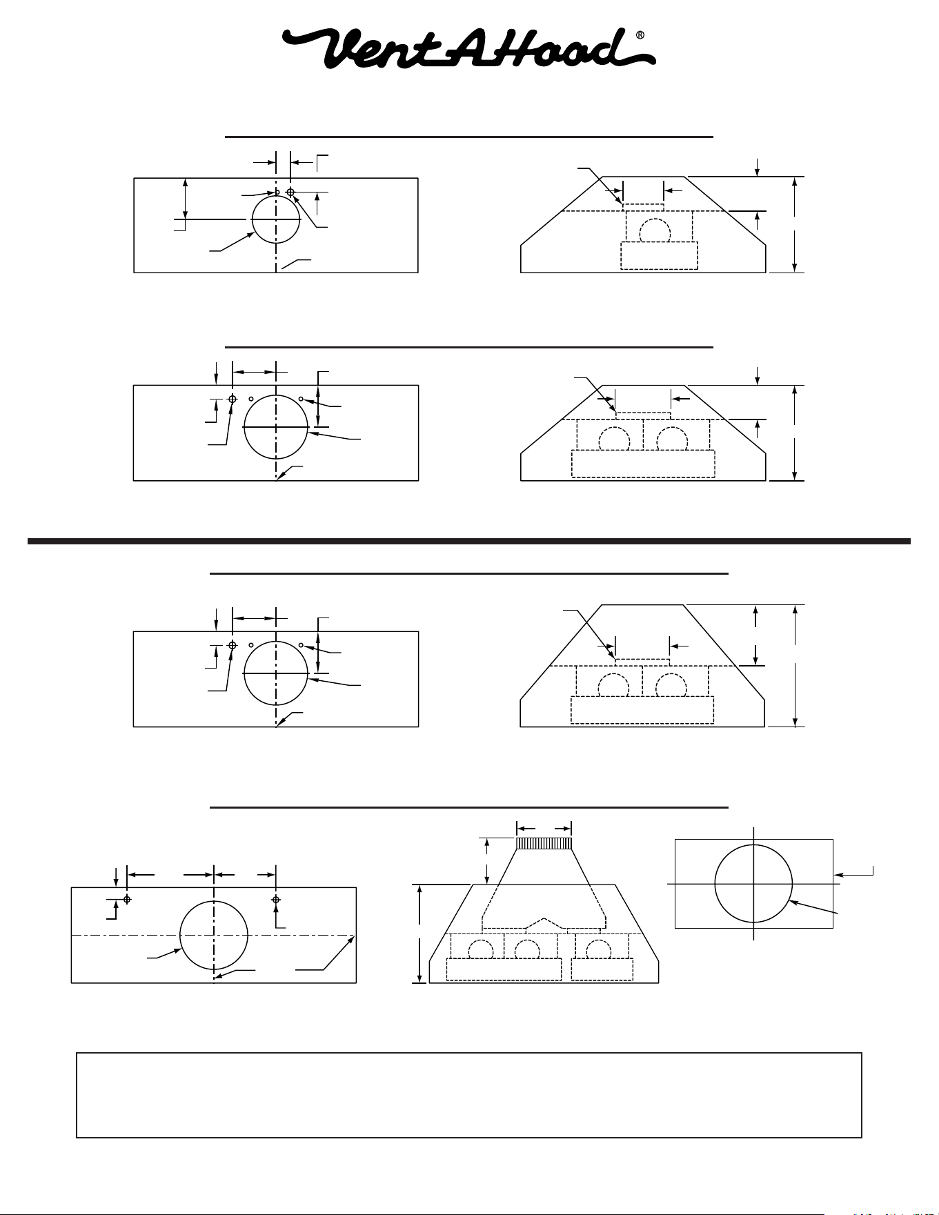
Centerline
Of Hood
Electrical
6" Outlet
Wall Side
Vent
Hole
1 7⁄8”
1 ¾”
5 ¼”
Blower
Exhaust
Outlet
5"
14"
6" Round
Electrical
1 ¾”
Centerline
of Hood
8” Outlet
Vent
Holes
5 ¼”5 ½”
Wall Side
14"
Blower
Exhaust
Outlet
5"
8" Round
Electrical
1 ¾”
Centerline
of Hood
8” Outlet
Vent
Holes
5 ¼”5 ½”
Wall Side
18"
Blower
Exhaust
Outlet
9"
8" Round
Centerline
Of Hood
Wall Side
Electrical (2)
10" Outlet
Centered On
Hood To p
12 7⁄8” 9 1⁄8”
1 ¾”
18"
10"
8 ½”
Duct Cover
(Top of Hood)
10" Dia. or 12" Dia.
T r ansition Location
"Centered"
Installation Details Continued
14” Tall Euroline Connection Diagram (30” - 48” Widths)
300 CFM B100 Single Blower
(Top View)
600 CFM B200 Dual Blower
(Top View)
(Front View)
(Front View)
18” Tall Euroline Pro Connection Diagram (36”- 48” Widths)
18” Tall Euroline Pro Connection Diagram (42”- 66” Widths)
The transition shown (VP562)
is installed in the hood at the
factory as a standard item.
It will be located in the exact
center of the duct cover (left to
right & front to rear).
600 CFM B200 Dual Blower
(Top View)
(Front View)
900 CFM B200 Dual & B100 Single Blower
(Top View)
VP562 Standard Transition
Installed (Front View)
See next page for 18” Tall Euroline Pro Connection
Diagram for 54” - 66” widths.
14” Tall Euroline Connection Diagram (36” - 48” Widths)
Loading ...
Loading ...
Loading ...