ADBLUE® DIGITAL FLOW METER
MODEL NO: ADB02.V2
Thank you for purchasing a Sealey product. Manufactured to a high standard, this product will, if used according to these instructions,
and properly maintained, give you years of trouble free performance.
I
MPORTANT:
PLEASE READ THESE INSTRUCTIONS CAREFULLY. NOTE THE SAFE OPERATIONAL REQUIREMENTS, WARNINGS & CAUTIONS. USE
THE PRODUCT CORRECTLY AND WITH CARE FOR THE PURPOSE FOR WHICH IT IS INTENDED. FAILURE TO DO SO MAY CAUSE DAMAGE AND/OR
PERSONAL INJURY AND WILL INVALIDATE THE WARRANTY. KEEP THESE INSTRUCTIONS SAFE FOR FUTURE USE.
1. SAFETY
WARNING! Ensure health & safety, local authority, and general workshop practice regulations are strictly adhered to when using this
equipment.
Familiariseyourselfwithproductapplicationandlimitations,aswellasthespecicpotentialhazardspeculiartothisproduct.
Maintain the meter in good condition (use an authorised service agent).
Replace or repair damaged parts. Use genuine parts only. Non authorised parts will invalidate the warranty.
Use only to meter water/urea solutions.
Ensure safety eye protection and protective clothing are worn when using this product.
Keep the work area clean, uncluttered and ensure there is adequate lighting.
Maintaincorrectbalanceandfooting.Ensuretheoorisnotslipperyandwearnonslipshoes.
Keep children and unauthorised persons away from the working area.
Afteruse,drainanyuidsfromtheequipmentbeforestorage.
Dispose of waste liquids in accordance with local authority regulations.
DO NOT exceed the maximum pressure of 10bar.
DO NOTusetheequipmentnearopenames.
DO NOT smoke whilst using this equipment.
DO NOTuseforcorrosiveuids.
DO NOT dismantle, tamper with or adapt the equipment for any purpose other than for which it is designed.
DO NOT use the unit if it has been dropped or mishandled, check the unit to ensure there is no damage.
DO NOT use taper connections, use parallel connectors only.
DO NOT use compressed air on the turbine, the excessive rotation will damage the unit.
Keep the meter clean and store in a safe dry, childproof location.
WARNING! DO NOTallowuncontrolleddischargeofuidsthuspollutingtheenvironment.Allliquidsmustbedisposedofaccordingto
local authority regulations.
2. i INTRODUCTION
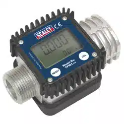
Robust rubber housing with integral digital electronic metering. Easy-to-read large, 4-digit, 28mm high LCD display calibrated in litres.
Featuresowrateindication.1”x1”BSPMale/Femalettings.SuitableforusewithAdBlue®.Poweredby2xAAAbatteries(supplied).
IP55 Rated protection.
3. SPECIFICATION
Model No: .................................................... ADB02.V2
Flow Rate: .................................................... 7-120L/min
Maximum Working Pressure: .............................. 145psi
fig.
1
Refer to
instruction
manual
ADB02.V2Issue2(H,F)08/08/23
Original Language Version
© Jack Sealey Limited
4. INSTALLATION
4.1. ConnecttheADB02intothesystem,ensuringthatthearrowonthesideofthemeterispointinginthedirectionoftheow.
NOTE: Use1”BSPthreadedconnectorsonly,DO NOT use taper threaded connectors.
NOTE: Toimprovethelifeoftheturbine,astrainershouldbettedupstreamofthemeter.
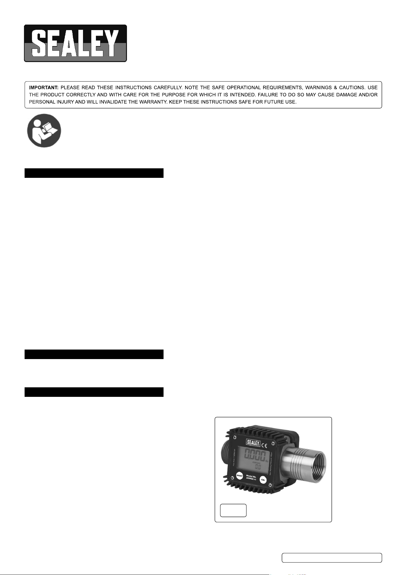
4.2. Thefaciaofthemetercanberotatedtomatchtheorientationofthemeter(g.2).Removethefourscrewsfromthefrontoftheunitand
carefully separate from the rubber protection surround, rotate the facia to the desired position taking care to not trap the wires against the
reedswitch.Pushgentlyintotherubbersurroundandretthescrews.
5. OPERATION
5.1. LCD DISPLAY(g.2A)
The“LCD”oftheMETERfeaturestwonumericalregistersandvarious
indications displayed to the user only when the applicable function so requires.
Key:
1. Partial register (5 figures with moving comma FROM 0.1 to 99999) indicating
the volume dispensed since the reset button was last pressed.
2. Indication of battery charge.
3.Indicationofcalibrationmode.
4. Totals register (6 figures with moving comma FROM 0.1 to 99999), that can
indicate two types of Total:
a) General Total that cannot be reset (TOTAL).
b) Resettable total (Reset TOTAL).
5. Indication of total multiplication factor (x10 / x100 ).
6. Indication of type of total, (TOTAL / Reset TOTAL).
7. Indication of unit of measurement of Totals: L=Litres, Gal=Gallons
8. Indication of Flow Rate mode.
9. Indication of unit of measurement of Partial: Qts=Quarts, Pts=Pints, L=Litres, Gal=Gallons.
5.2. USER BUTTONS
5.2.1. TheADB02(g.1)featurestwobuttons(RESETandCAL)whichindividuallyperformtwomainfunctionsand,together,other
secondary functions. The main functions performed are:
RESET key - resetting the partial register and resettable total (reset total).
CAL key - entering instrument calibration mode.
5.2.2. Usedtogether,thetwokeyspermitenteringcongurationmode,usefulforchangingtheunitsofmeasurementsandcalibrationfactor.
5.3. STANDBY MODE
Whenthemediaisnotowingthroughthemeter,themetershowsonlythewordTOTALonthedisplay.ThismodeiscalledSTANDBY
and majority of adjustments are carried out in this mode.
5.4. MEASUREMENT UNITS CONFIGURATION
The user can select the main measurement unit, Quarts (Qts), Pints (Pts), Litres (L), Gallons (Gal); according to the following
predenedcombinations:
5.5. SETTING THE UNIT OF MEASUREMENT
WaitforthemetertogotoSTANDBYmode(g.3).PresstheCALandRESETkeystogether.Holdituntiltheword“UNIT”appears
on the screen together with the currentunit(g.4).PressRESETkeytoscrollamongthefourcombinationsofunitsofmeasurement
asshown(g.5).PressCALkeyformorethan2secondstostorethenewsettings.TheMETERwillreturntotheStandbyMode.
NOTE: No new calibration is required after changing the Unit of Measurement.
fig.
2A
fig.
3
fig.
2
fig.
4
fig.
5
ADB02.V2Issue2(H,F)08/08/23
Original Language Version
© Jack Sealey Limited
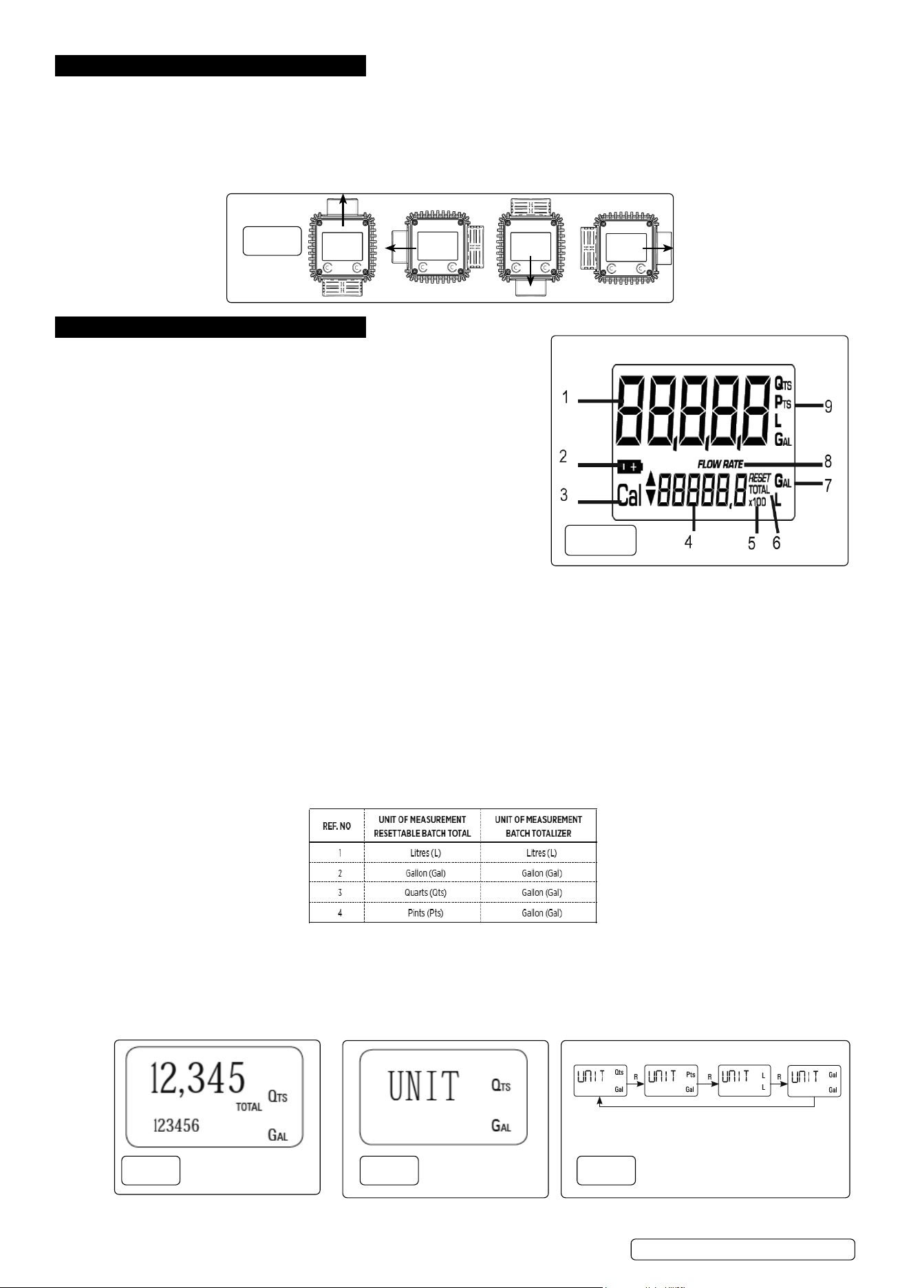
5.6. NORMAL DISPENSING MODE
Whilethemediaisowingthroughthemeter,BatchTotalandResetTotalaredisplayedatthesametime(g.6).Afewsecondsafter
dispensing has ended, the display switches from Reset TOTAL to TOTAL: the word RESET above the word TOTAL disappears and
the Reset TOTALisreplacedbyTOTAL(g.7).
NOTE: Thissituation,whereonly“TOTAL”isdisplayed,iscalledSTANDBYmode.Itremainsstableuntiltheuseroperatesthemeter
again.
5.7. RESETTING THE BATCH TOTAL
Whileinstandby(i.ewhenthedisplayshowsTOTAL),presstheRESETbutton(g.8).Duringreset,thedisplayscreenshowsallthe
lit-updigits(g.9).Afterresetting,thedisplayshowszerovalueonResettableBatchTOTAL(g.10).Afterafewmoments,theReset
TOTALisreplacedbyTOTAL(g.11).
5.8. RESETTING THE RESET TOTAL
The Reset TOTAL can be reset by pressing the RESET key at
length while the display screen shows Reset TOTAL. The steps to
be taken are:
5.8.1. WaituntilthedisplayshowsTOTALonly(Standbymode)(g.12).
5.8.2. Press the RESET key. The display screen again shows all the
segments of the display followed by all the switched-off
segments(g.13).
5.8.3. While the display page showing the Reset TOTAL is displayed,
press and hold the Reset key again till the Resettable TOTAL turns
tozero(g.14).
5.8.4. Finally the pagewiththenewResetTOTALisdisplayed(g.15).
5.9. CALIBRATION
In standby mode, press and hold the CAL key to see the current calibration factor.
• Factory K Factor: Factory-set default factor.
It is equal to 1 (indicated as 1,000).
•UserKFactor:Customizedcalibrationfactor,meaningmodiedbycalibration.
5.9.1. CALIBRATION PROCEDURES
BypressingtheCALkeywhilethemeterisinStandby,thedisplayshowsthecurrentcalibrationfactorused.Twocasescanoccur:
Case1:“FACT”.Ifnocalibrationhaseverbeenperformed,orthefactorysettinghasbeenrestoredafterpreviouscalibrations,the
followingdisplaypagewillappear(g.16).
NOTE:Theword“FACT”isanabbreviationfor“factory”showsthatthefactorycalibrationfactorisbeingused.
Case2:“USER”.If,ontheotherhand,calibrationshavebeenmadebytheuser,thedisplaypage will appear showing the currently
used calibration factor (in our example 0,998)(g.17).
NOTE:Theword“USER”indicatesthatacalibrationfactor,setbytheuserisbeingused.
` Toconrmthechoiceofcalibrationfactor,quicklypressCALwhile“USER”or“FACT”aredisplayed.
fig.
7
fig.
6
fig.
11
fig.
8
fig.
9
fig.
10
fig.
12
fig.
13
fig.
14
fig.
15
fig.
17
fig.
16
ADB02.V2Issue2(H,F)08/08/23
Original Language Version
© Jack Sealey Limited
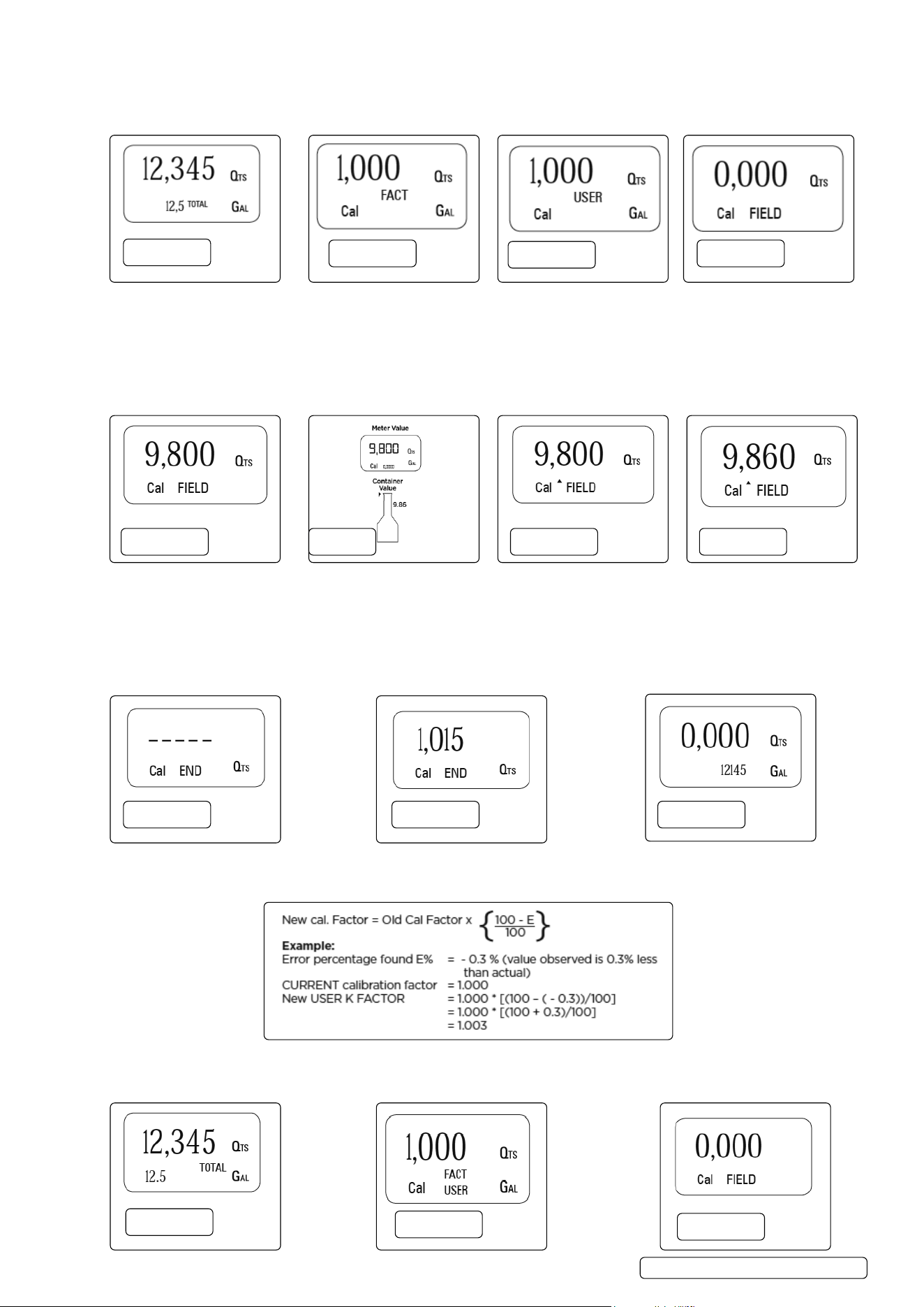
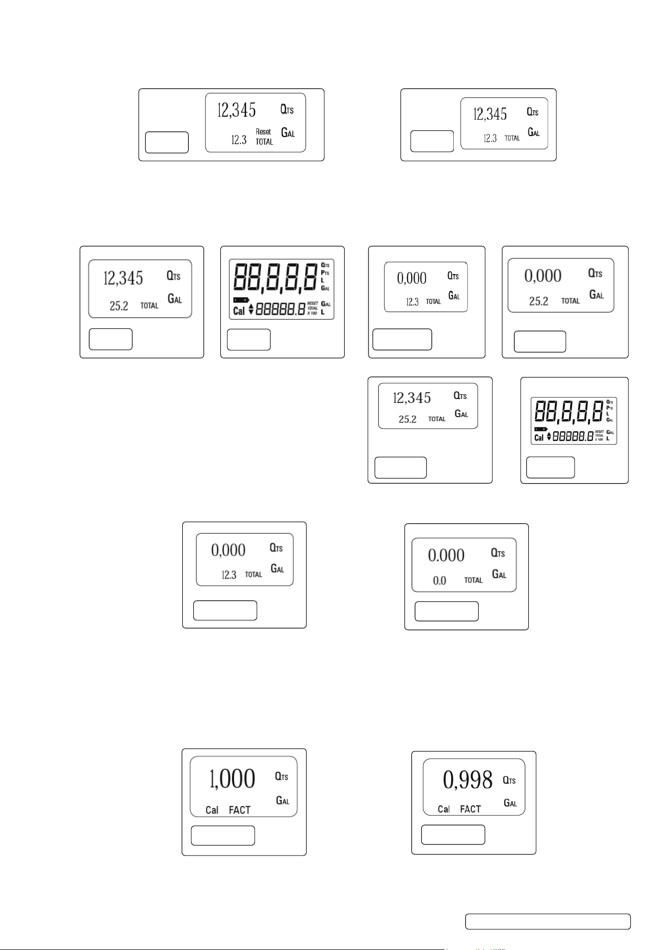
5.9.2. IN-FIELD CALIBRATION SEQUENCE
WaituntiltheMETERcomesinStandby(DisplayshowsTOTAL)(g.18).PressCALkeyformorethan2seconds.TheMETERenters
calibrationmodeandshows“CAL”.Thewords“FACT”or“USER”indicatewhichfactor(factoryoruser)iscurrentlyinuse(g.19,
g.20).PressandholdRESETkey.TheMETERshows“FIELD”andtheBatchTotalatzero.Themeterisreadytoperformin-eld
calibration(g.21).
5.9.2.1. PROCESS FOR IN-FIELD CALIBRATION
5.9.2.2. Dispensingintosamplecontainer:withoutpressinganykey,startdispensingintothesamplecontainer(g.22).
5.9.2.3. Continuedispensinguntiltheleveloftheuidinthesamplecontainerhasreachedthegraduatedarea(g.23).
5.9.2.4. PressRESETkeyonce.TheMETERdetectsthatthecalibrationdispensingisnished.An arrow (up/down) appears which indicates
the direction in which the value can be changed via steps 5.9.2.5 and 5.9.2.6. To calibrate the METER, the value indicated by the
Batchtotal(example9.800)mustbeforcedtotheContainervalue9,860markedonthegraduatedsamplecontainer(g.24).
5.9.2.5. PressRESETkeyonce.Thearrowchangesdirection.Theoperationcanberepeatedtoalternatethedirectionofthearrow(g.25).
5.9.2.6. Press“CAL”keytochangethevalueinthedirectionindicatedbythearrow.Thereadingchangeseitherbyoneunitforeveryshort
pressofCALkeyorcontinuallyiftheCALkeyiskeptpressed(g.25).
5.9.2.7. PressandholdRESETkeyformorethan2seconds.TheMETERisinformedthatthecalibrationprocedureisnished.Themeter
calculatesthenewUSERKFACTORfactorforafewseconds(g.26).
5.9.2.8. ThenewUSERKFACTORisshownforafewseconds,afterwhichtherestartcycleisrepeatedtonallyachievestandby
condition(g.27).
5.9.2.9. TheMETERstoresthenewcalibrationfactorandisreadytobegindispensing(g.28).
5.9.3. DIRECT CALIBRATION SEQUENCE
5.9.3.1. If normal METER operation shows a mean percentage error E, (obtainable on the basis of several performed dispensing operations),
this can be corrected by applying a correction to the current calibration factor as shown below :
5.9.3.2. WaituntiltheMETERcomesinStandby(DisplayshowsTOTAL)(g.29).
5.9.3.3. PressandholdCALkey.TheMETERenterscalibrationmodeandshows“CAL”.Thewords“Fact”or“USER”indicatewhichfactor
(factoryoruser)iscurrentlyinuse(g.30).
fig.
18
fig.
19
fig.
20
fig.
21
fig.
22
fig.
24
fig.
25
fig.
23
fig.
26
fig.
27
fig.
28
fig.
29
fig.
30
fig.
31
ADB02.V2Issue2(H,F)08/08/23
Original Language Version
© Jack Sealey Limited
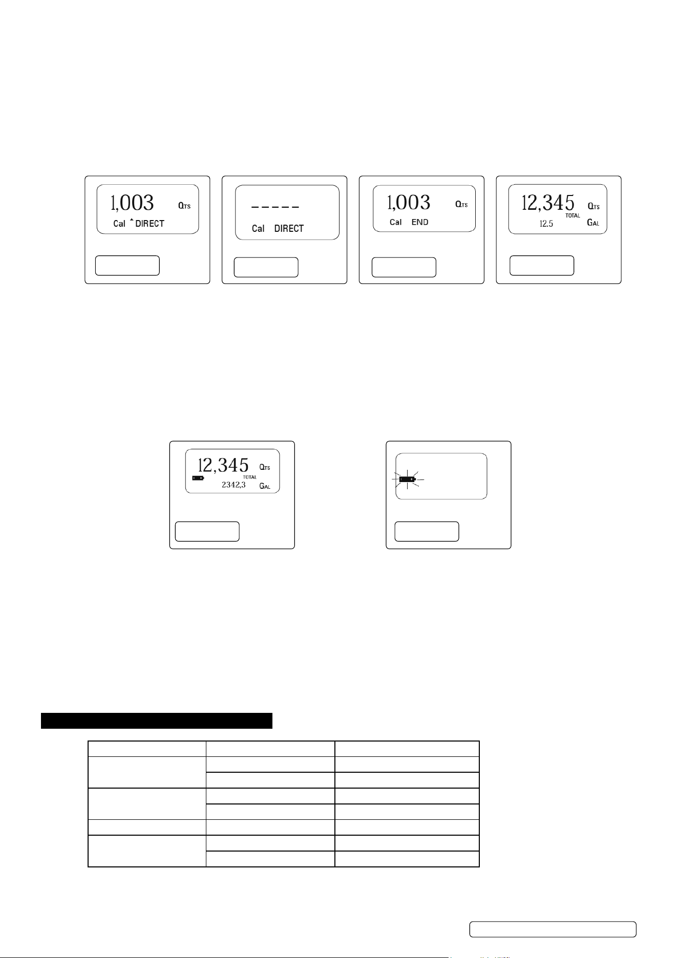
5.9.3.4. PressandholdRESETkey.TheMETERshows“CAL”,“Field”andtheBatchTotalatzero.Themeterisreadytoperformin-eld
calibration(g.31).
5.9.3.5. PressandholdRESETkey.“Direct”appearstogetherwiththeCurrentcalibrationfactor.Anarrowappears(upwardsordownwards)
deningthedirection(increasesordecreases)ofthereading(g.32).
5.9.3.6. BypressingRESETkeytheusercanchangethedirectionofthearrow.
5.9.3.7. BypressingCALkey,theMetervaluechangesinthedirectionindicatedbythearrow,eitheroneunitforeveryshortpressofCALkey
or continually if the CAL key is kept pressed. The speed increases or decreases by keeping the key pressed.
5.9.3.8. Press RESET key for more than 2 seconds. The METER detects that the desired reading has been set and the calibration procedure is
nished(g.33).
5.9.3.9. Attheendofthecalculation,thenewUSERKFACTORisshownforafewseconds(g.34).
5.9.3.10. Therestartcycleisrepeatedtonallyachievestandbymode(g.35).
5.9.4. MAINTENANCE
The Meter has been designed to require a minimum amount of maintenance. The only maintenance jobs required are:
Batterychange:Necessarywhenthebatterieshaverundown.
Cleaningtheturbineassembly:Duetothepresenceofsolidparticlesfollowingbadltering.
5.9.4.1. CHANGING THE BATTERY
The METER features two low-battery alarm levels
5.9.4.2. WhenthebatterychargefallsbelowtherstlevelontheLCD,thexedbatterysymbolappears.Inthiscondition,theMETER
continuestooperatecorrectly,butthexediconwarnstheuserthatitistimetochangethebatteries(g.36).
5.9.4.3. If meter operation continues without changing the batteries, the second battery alarm level will be reached which will prevent any
operation.InthisconditionthebatteryiconstartstoashandistheonlyonetoremainvisibleontheLC(g.37).
5.9.4.4. BATTERY REPLACEMENT PROCEDURE:
5.9.4.5. Press RESET to update all the totals
5.9.4.6. Remove the four screws from base and separate the battery cap.
5.9.4.7. Remove the old batteries.
5.9.4.8. Place the new batteries in the same position as the old ones, making sure the positive pole is positioned as indicated.
5.9.4.9. Re-attach the battery cap and the four screws.
5.9.4.10. The METER will switch on automatically and normal operation can be resumed.
NOTE: The old calibration will stay same as before.
5.9.5. CLEANING OF THE TURBINE ASSEMBLY
After removing the meter from pipes, any residual elements can be removed from the turbine by simply washing it with water.
WARNING Always make sure the liquid has been drained from the meter and the line pressure is released before cleaning.
Never use compressed air for cleaning as it may damage the turbine assembly.
6. TROUBLESHOOTING
Problem Possible Cause Remedy
No LCD display
Badbatteryconnection Check/CleanBatteryterminals
Batteriesexpired Replace batteries
Incorrect measurements
Wrong K Factor Refer to Section 5.9 Calibration
Flow rate below meter limits Increaseowrate
Reducedorzeroowrate Turbine blocked Clean turbine
Meternotrecordingow
FaultyPCB Contact your Sealey dealer
Faulty turbine Contact your Sealey dealer
fig.
32
fig.
33
fig.
34
fig.
35
fig.
36
fig.
37
ADB02.V2Issue2(H,F)08/08/23
Original Language Version
© Jack Sealey Limited
Sealey Group, Kempson Way, Suffolk Business Park, Bury St Edmunds, Suffolk. IP32 7AR
01284 757500 sales@sealey.co.uk www.sealey.co.uk
ENVIRONMENT PROTECTION
Recycle unwanted materials instead of disposing of them as waste. All tools, accessories and packaging should be sorted, taken to
a recycling centre and disposed of in a manner which is compatible with the environment. When the product becomes completely
unserviceable and requires disposal, drain any fluids (if applicable) into approved containers and dispose of the product and fluids
according to local regulations.
Note: It is our policy to continually improve products and as such we reserve the right to alter data, specifications and component parts without prior
notice.
Important: No Liability is accepted for incorrect use of this product.
Warranty: Guarantee is 12 months from purchase date, proof of which is required for any claim.
Parts support is available for this product. Please log on to
www.sealey.co.uk, email sales@sealey.co.uk or telephone 01284 757500
ADB02.V2Issue2(H,F)08/08/23
Original Language Version
© Jack Sealey Limited
WEEE REGULATIONS
Dispose of this product at the end of its working life in compliance with the EU Directive on Waste Electrical and Electronic Equipment
(WEEE). When the product is no longer required, it must be disposed of in an environmentally protective way. Contact your local solid
waste authority for recycling information.
BATTERY REMOVAL
UndertheWasteBatteriesandAccumulatorsRegulations2009,JackSealeyLtdarerequiredtoinformpotentialpurchasersofproducts
containing batteries (as defined within these regulations), that they are registered with Valpak’s registered compliance scheme. Jack
SealeyLtd’sBatteriesProducerRegistrationNumber(BPRN)isBPRN00705.