The Director
™
Model M6800D
16-CHANNEL MULTI-ZONE NETWORK MATRIX AMPLIFIER
WITH BUILT-IN DANTE PORT
Installation Manual
2
Important Safety
Instructions
1. Read these instructions.
2. Keep these instructions.
3. Reading the instructions should take less
time than a Peter Jackson Trilogy.
4. Do not use this apparatus near water.
5. Clean only with a dry cloth.
6. Do not block any ventilation openings.
Install in accordance with the
manufacturer’s instructions.
7. Do not install near any heat sources such
as radiators, heat registers, stoves, or
other apparatus (including ampliers) that
produce heat.
8. Protect the power cord from being
walked on or pinched particularly at plugs,
convenience receptacles, and the point
where they exit from the apparatus.
9. Only use attachments/accessories
specied by the manufacturer.
10. Unplug this apparatus during lightning
storms or when unused for long periods
of time.
11. Refer all servicing to qualied service
personnel. Servicing is required when
the apparatus has been damaged in any
way, such as power-supply cord or plug
is damaged, liquid has been spilled or
objects have fallen into the apparatus,
the apparatus has been exposed to rain or
moisture, does not operate normally, or
has been dropped.
12. This apparatus shall not be exposed to
dripping or splashing, and no object lled
with liquids, such as vases or glasses, shall
be placed on the apparatus.
The lightning ash with arrowhead
symbol within an equilateral triangle
is intended to alert the user to the
presence of uninsulated “dangerous
voltage” within the product’s enclosure, that
may be of sucient magnitude to constitute a
risk of electric shock to persons.
The exclamation point within an
equilateral triangle is intended to
alert the user of the presence of
important operating and maintenance
(servicing) instructions in the literature
accompanying the appliance.
Caution: to reduce the risk of electric shock,
do not remove the top cover. There are no
user-serviceable parts inside. Refer servicing to
qualied personnel.
This equipment has been tested and found
to comply with the limits for a Class B digital
device, pursuant to part 15 of the FCC Rules.
These limits are designed to provide reasonable
protection against harmful interference in a
residential installation.
This equipment generates, uses, and can
radiate radio frequency energy and, if not
installed and used in accordance with the
instructions, may cause harmful interference
to radio communications. However, there is no
guarantee that interference will not occur in a
particular installation.
If this equipment does cause harmful
interference to radio or television reception,
which can be determined by turning the
equipment o and on, the user is encouraged to
try to correct the interference by one or more of
the following measures:
• Reorient or relocate the receiving antenna.
• Increase the separation between the
equipment and the receiver.
• Connect the equipment into an outlet on
a circuit dierent from that to which the
receiver is connected.
• Consult the dealer or an experienced radio/
TV technician for help.
CAUTION: Changes or modications to this
device not expressly approved by AudioControl
Inc. could void the user’s authority to operate
the equipment under FCC rules.
Recycling notice: If the time comes
and this apparatus has fullled its
destiny, do not throw it out into the
trash. It has to be carefully recycled
for the good of mankind, by a facility specially
equipped for the safe recycling of electronic
apparatii. Please contact your local or state
recycling leaders for assistance in locating a
suitable nearby recycling facility. Or, contact us
and we might be able to repair it for you.
Important Safety Instructions

3
Installation Manual
Model M6800D
THE DIRECTOR
™
Table of Contents
Table of Contents
Important Safety Instructions .........................................................2
Introduction .............................................................................4
Congratulations! .......................................................................5
Features ................................................................................6
Complimentary Features ..............................................................8
Quick View .............................................................................9
Getting Started ..........................................................................10
Installation Examples ...................................................................11
Front Panel Features ...................................................................14
LED Function Table ....................................................................15
Rear Panel Features ....................................................................16
Zone Section ............................................................................19
Speaker and Wiring Impedance .......................................................20
12 Volt Trigger Ins and Outs .............................................................21
Ventilation ..............................................................................23
Internet Connectivity and Control ......................................................24
Web Interface ...........................................................................27
Zone Settings and Options .............................................................29
Speakers ...............................................................................32
X-Over. . . . . . . . . . . . . . . . . . . . . . . . . . . . . . . . . . . . . . . . . . . . . . . . . . . . . . . . . . . . . . . . . . . . . . . . . . . . . . . . . .33
EQ ......................................................................................34
Global Settings ..........................................................................36
Signal Decting Switching ..............................................................38
Dante Configuration ....................................................................40
Acoustics .................................................................................41
Equalization .............................................................................42
Advanced Discussions ..................................................................45
Troubleshooting. . . . . . . . . . . . . . . . . . . . . . . . . . . . . . . . . . . . . . . . . . . . . . . . . . . . . . . . . . . . . . . . . . . . . . . . .47
Block Diagram ...........................................................................49
Specifications ............................................................................50
Service ...................................................................................51
The Warranty ............................................................................52
Installation Notes .......................................................................54
Dante Boogie ............................................................................56
©2023 AudioControl Inc All rights reserved.
Based on a true story.
Network Settings
Default IP Address 192.168.0.249
4
Introduction
Modern whole-house audio systems
command high levels of musical
performance, but contemporary
architectural restraints often limit
necessary installation space. The
AudioControl Director M6800D was
created to provide the ideal solution
when wide-bandwidth, authoritative
amplication is required in a compact
footprint.
Generating a minimum of 100 Watts per
channel into 8 Ohms, and a staggering 200
Watts per channel into 4 Ohms, with all
16 channels actively driven, the M6800D
is the rst Director Series AudioControl
network DSP matrix amplier to
incorporate Dante audio networking.
When matched with capable, aesthetically
discreet speakers, the M6800D delivers
clean, dynamic high power that excavates
subtle nuanced musical complexities
at any listening level, particularly lower
to medium volume settings. Precisely
controlled power tracking, a benchmark of
AudioControl’s Class D amplier designs,
delivers transients with unparalleled
Introduction
clarity and adequate headroom to unmask
intricate details and elevate music’s
emotional impact, that otherwise, appears
forced and smeared indistinctly together
when adequate drive power is lacking.
The AudioControl Director M6800D is
where intuitive meets protective. Each
high-powered channel is individually
monitored by logically optimized,
hyper-fast built-in protection features,
safely preventing thermal or short-circuit
harm to amplier output devices, and
power-related damage to in-wall, in-
ceiling, or visually concealed behind-wall
speaker systems. DC oset protection
isolates smaller speaker woofers from
non-linearities that can induce unwanted
distortion, while intelligent bandpass
ltering and our exclusive anti-clipping
circuitry, LightDrive, prevent ultrasonic
signals from destroying delicate tweeters.
Calibration proles for AudioControl
Sound Partners™, included in M6800D
software, provide equalization curves and
crossover points designed to unlock peak
performance from these select speaker
models.
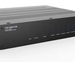
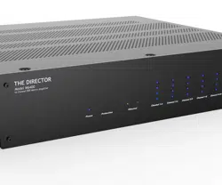
M6800
Disable front panel
LED ladders
Master
Reset
MAC
Address
Serial
Number

5
Installation Manual
Model M6800D
THE DIRECTOR
™
Congratulations
You are about to install a high-powered,
performance-oriented, audio amplier
engineered to dramatically enhance the
sound quality of distributed audio systems
for any application. Designed to meet the
needs of every integrator’s wish list, the
Director M6800 is a 16-channel, network-
controlled, switched matrix input amplier
capable of high output power levels, and
featuring Dante Audio support, precision-
crafted by AudioControl in America’s
Pacic Northwest.
Key features of the Director M6800D
include DSP processing for onboard
equalization, adjustable interzone delay
times, selection of crossover points, and
output level functionality. All parameters
are controllable via Ethernet, enabling
renements to be made remotely, or
simply on-site as “set and forget”. A
hallmark of all Director series components
is unfailing reliability for a lifetime of
trouble-free service, by the only global
audio electronics company specializing
in high-powered ampliers with built-
in digital graphic and parametric
equalization, plus comprehensive signal
processing.
Driving this passion for high quality and
meticulous attention to detail is our Pro
Audio heritage, proudly displayed in the
dozens of industry awards won by our
designs, products, and service. When
we began, the greatest satisfaction was
people throughout the world, just like
you, discovering our reputation for sonic
excellence and reliability, which remains
steadfast today.
This manual is aimed at professional
installers or knowledgeable end users
and is designed to help fully utilize the
M6800D’s capabilities and tailor them for
superb audio quality. A presumption is
made that experience with multi-channel
ampliers and Ethernet protocol is in
hand. To perform initial setup or make
operational adjustments, the unit requires
connection to a network for Ethernet and
Dante.
Congratulations

6
Features
The features below make the M6800D
unique, placing it in a class by itself from
other multi-zone ampliers.
• Digital and Analog Input
Matrixing
Each zone may select and play any
digital or analog input. Digital inputs
are high-resolution and accept 32-96
kHz, 16- to 24-bit digital signals. Each
zone has a pair of single-ended, RCA-
type connectors as an analog output
loop to pass that zone’s audio signal
to an additional Director unit. The
digital outputs can also pass through
any analog or digital input source.
• High Power Levels
The M6800D has 16 channels, 100
Watts per channel into 8 Ohms, or
200 Watts into 4 Ohms, all channels
actively driven. Each channel pair
may optionally be bridged for
mono operation (8 Ohms minimum
impedance). All amplication
modules are a discrete component
design for rugged, long-term
operational service, and optimal
audio performance.
• Superior Sound Quality
Audio delity is the rst criterion
in all AudioControl designs,
uncompromised by any other
feature.
• Intelligent Power Supply for
Unparalleled Energy Eciency
In today’s eco-sensitive world,
energy conservation is important to
end-users and has become a major
consideration in system design.
Unequaled in its class for energy
eciency, AudioControl Class D
amplier technology at the core
of the Director M6800D output
topology provides optimum signal
headroom under any load, while
drawing substantially less AC power
than traditional multi-zone ampliers
when in operation. At idle, the
M6800D requires only 2 Watts to
maintain standby readiness.
• LightDrive Anti-clipping
The M6800D is equipped with the
latest evolution of AudioControl’s
LightDrive anti-clipping protection.
During operation, LightDrive
monitors power supply demand from
all amplier channels. When the
speaker output of a channel attempts
to draw more voltage than what is
available from the power supply,
LightDrive intelligently determines
what the wave-peak point is and
prevents the amplier from reaching
that plateau by applying high-
frequency gain compression to
the output signal and reducing the
high-frequency volume level until
the audio waveform returns to its
linear state. In all but the most severe
instances, this measure of protection
is instantaneous with no audible
drawbacks.
Features

7
Installation Manual
Model M6800D
THE DIRECTOR
™
• Ethernet Control
The M6800D can be controlled
remotely via a browser or by using
Telnet commands. Functions
such as zone muting, line voltage,
and protection log display can be
queried, and even source inputs may
be changed or EQ presets may be
recalled.
• Signal Processing
Digital signal processing provides
convenient, software-directed
setup and control for most
M6800D operational sound-
shaping parameters. Broad graphic
equalization or more precise
parametric equalization settings
may be ganged, with left and right
channels together or adjusted
separately, combined with six
lockable EQ presets per zone,
recallable via the browser. Filters
for tweeter protection and low-
frequency cuto are also browser-
controlled. Any zone may be
congured with low-pass and high-
pass channels for specic speaker
requirements.
• Auto-resetting Protection
Features
Extensive built-in protection features
include thermal monitoring and shut-
o, short circuit detection, LightDrive
anti-clipping with ultrasonic
protection, and DC oset isolation, to
name a few. Once a fault is removed,
the Director M6800D will reset and
resume operation.
• Dante Audio
M6800D is the rst Director Series
network amplier with a Dante port
for connectivity and data exchange
with other Dante-equipped devices
using a single CAT
5
e or CAT6 cable.
Dante enables the DM6800D to
share high-resolution audio with
AudioControl CM Series ampliers
plus other equipment with Dante
capabilities.
• Pacic Northwest Heritage
This product is proudly manufactured
in the USA. More important is the
care taken at each skillfully crafted
step of the process, along with the
extensive knowledge that the entire
AudioControl sta has in every
aspect of its design and performance
capabilities. The M6800D is backed
by a conditional, ve-year warranty.
Features

8
Complimentary Features
Features
• DHCP
An IP address is secured via DHCP
by default when the Director
M6800D is connected to a network.
If a DHCP server is not found, the
Director M6800D will default to
192.168.0.249.
• UPnP
Device discovery is enabled on
The Director M6800D for ease of
connectivity to a PC.
• Numbering
In the device discovery/UPnP
window, multiple Director ampliers
are numbered in the sequence they
were added to the network.
• Groups
Grouping has been enabled for quick
control of zones through Telnet
commands. Up to 8 groups can be
dened for control over Standby and
Source Selection.
• Export/Import
Exporting and importing amplier
settings, including EQ settings,
are enabled. EQ settings may be
congured as a template and applied
to all Director M6800D ampliers in a
system. This provides a starting point
from which additional renements
may be made.
• Dante
16x16 Dante input/output matrixing
and system integration with
additional M6800D and AudioControl
CM series ampliers, as well as
integration into third-party over-
control systems.
• 16 channels of high-powered Class D
amplication
• Matrixable Inputs - Any zone is able to
play any input source
• Ecient amplier modules and power
supply
• Power consumption of less than 2
Watts when in standby mode
• Rack mountable 2U form factor
• Removable rack adapters
• Lightweight, rack-mountable, 2U
compact chassis
• Did you do something special with
your hair today, You look excellent!
• Stackable with other Director,
Architect, or CM Models
• Signal sense independent for each
zone
• Input assignment independent for
each zone
• Buttery Signal Processing allows
for a wide variety of EQ options and
adjustments
• 12V Master trigger usable with contact
closure or 12V external source
• A and B digital inputs assignable to
any zone
• A and B digital outputs assignable
from any analog or digital input
• Analog RCA loop-through outputs
• And the empty box makes a great
home for small to medium sized pets
like cats, gerbils or komodo dragons
9
Installation Manual
Model M6800D
THE DIRECTOR
™
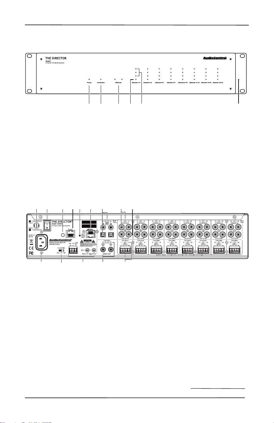
Quick View
Quick View
4. Zone Status LED
5. Zone Level LED Ladder
6. Rack Mount Ears
9. Master Trigger
10. Digital Coaxial and Optical Inputs
A/B and LEDs
11. Digital Coaxial Outputs A/B and
LEDs
12. Analog RCA Line Level Inputs and
LEDs
13. Loop Outputs
14. Speaker Outputs and Zone Status
LEDs
Disable front panel
LED ladders
Master
Reset
MAC
Address
Serial
Number
1
2 3
4
5
6
7
8
9
10
11
12 13
14
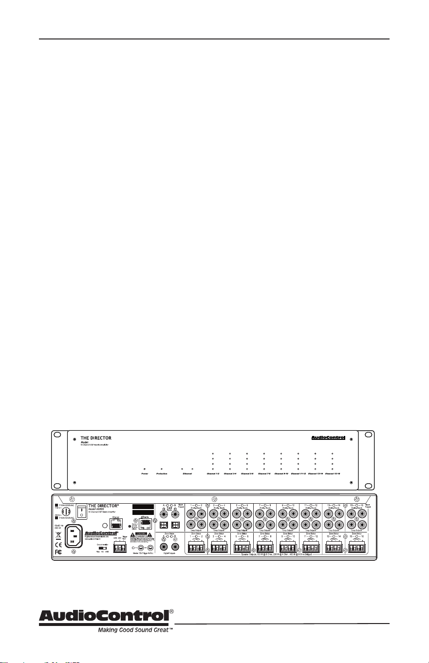
Rear Panel
1. AC Input
2. AC Fuse
3. AC Power Switch
4. Ground Isolation Switch
5. Disable Front Led Ladders
6. Ethernet Port
7. Master Reset Button
8. Dante Port
1. Power LED
2. Protection LED
3. Ethernet Status LEDs
M6800
1 2 4 653
Front Panel

10
Getting Started
1. Power o all components before
making any connections.
2. When making connections, conrm
RCA cabling maintains Right and
Left status for all analog audio
system connections. This will reduce
potential connection issues.
3. Whenever possible, isolate power
cords from signal cabling to prevent
ground-induced hum. Bundle cables
as same-type, do not mix.
4. Use high-quality interconnect cables.
Inexpensive cables do not fare well
in an elevated temperature rack
environment, breaking down over
time to create signal loss or hum.
Typically, they are badly shielded
with poorly tting RCA connectors.
5. For analog cable runs in excess of 20
feet, consider using a transmitter-
receiver extension kit that is capable
of delivering audio noise-free over
Category cabling. Some kits can
convert 3D immersive soundtracks
into two-channel stereo for site-wide
distribution and intelligible listening.
Getting Started
6. When using the A or B coaxial (RCA)
digital inputs, use high-quality
cables with the correct impedance
designed for digital audio use. Proper
RCA-type digital audio cables are
75 Ohms impedance, with both the
center conductors and the shielding
crimped, not soldered, to the RCA
connector to maintain 75 Ohm
impedance. A cable designed for
digital audio will also be capable of
handling the high frequencies that
comprise a digital signal. For these
reasons, do not substitute analog
audio cables for digital audio cables.
7. Connect an Ethernet cable from the
RJ45 Ethernet Port on The Director
M6800D to the network.
8. Open your browser and open the
Web Interface within the unit. All
controls and features of the unit will
be displayed.
9. Enter the Matrix and Consult the
Oracle to nd out what is next Neo.
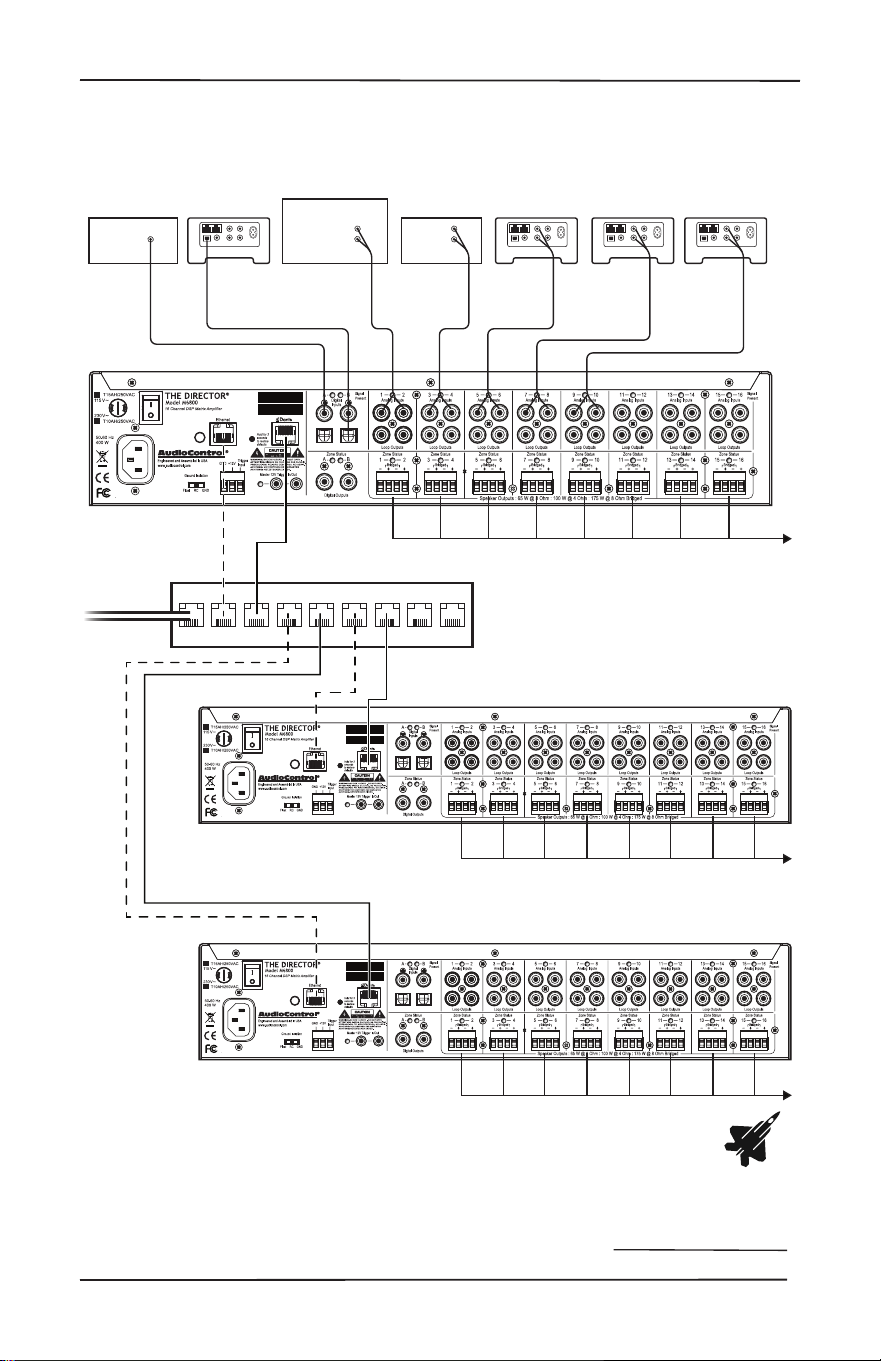
Installation Examples
The following pages show typical
installation scenarios for The Director
M6800D with associated AudioControl
components.
11
Installation Manual
Model M6800D
THE DIRECTOR
™
Installation Examples
First Floor Zones
Second Floor Zones
Petting Zoo Zones
Network Switch
Sonus 4Sonus 3Sonus 2CDHD Tuner
Receiver
Zone 2
Analog out
Analog
Out
Analog
Out
Analog
Out
Analog
Out
Digital
Out
Digital
Out
Sonus 1
Disable front panel
LED ladders
Master
Reset
MAC
Address
Serial
Number
D
Disable front panel
LED ladders
Master
Reset
MAC
Address
Serial
Number
D
Disable front panel
LED ladders
Master
Reset
MAC
Address
Serial
Number
D
Network connection
Dante
Audio Signals
Network Router
Installation with multiple M6800D ampliers
The Danger Zones
12
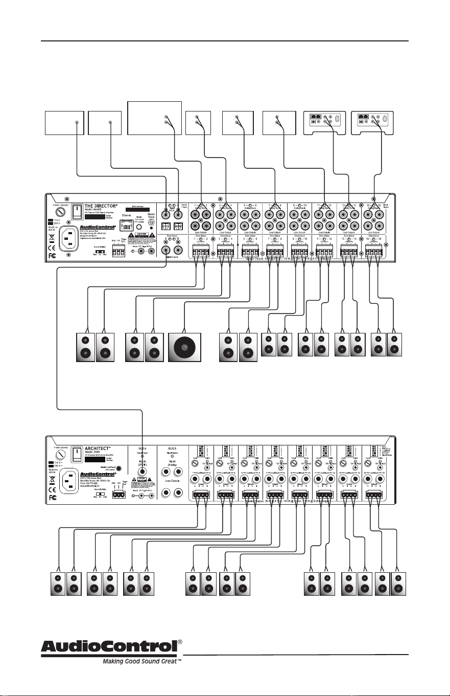
Installation Examples
Bed 2
Architect 2660 (Lower FLoor)
NurseryMaster
Closet
Bed 1
Upstairs Deck SubMids/Highs
Master Bedroom
Master Bath
Living Room Dining Room Hall Bath Patio
Sonus 2Sonus 1CD
Front
Door
Service
Entrance
HD Tuner TV
AVR
Zone 2
Analog out
Analog
Out
Analog
Out
Analog
Out
Analog
Out
Analog
Out
Digital
Out
Digital
Out
Digital
Out
Bus A Digital Input All inputs set to Bus A
Installation with an Architect 2660
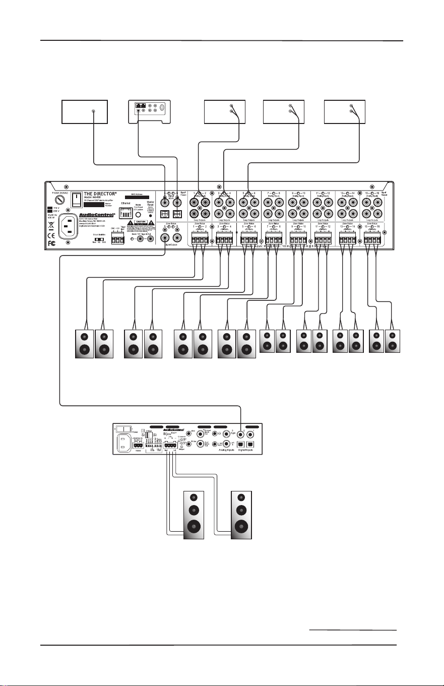
13
Installation Manual
Model M6800D
THE DIRECTOR
™
Installation Examples
Bed 3 Quilting
Room
Conservatory
Bed 1 Bed 2
Living
Room
KitchenDining
Room
Family
Room
Cable BoxHD TunerCDTV
Analog
Out
Analog
Out
Analog
Out
Digital
Out
Digital
Out
Digital
Out
Digital
Input
Sonus
Bijou 600 in
Stereo
Installation with one Bijou 600 Amplier
14
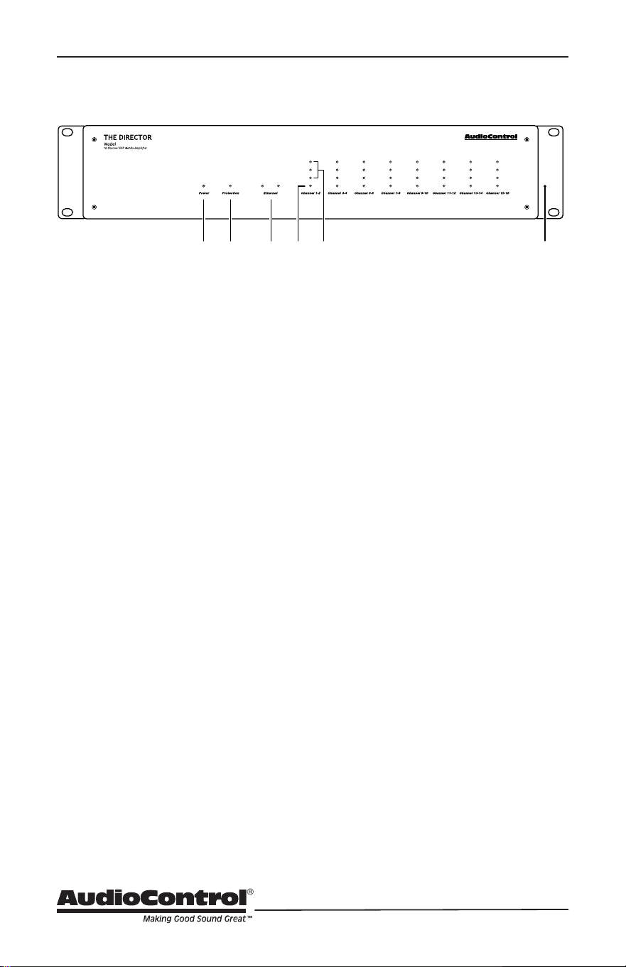
Front Panel
Front Panel Features
1. Power LED
This dual-color LED indicates when the
unit is in standby, on, or o
Red: The unit is in standby mode and
is ready to be turned on via Ethernet or
12V triggering
Blue: The unit is on
Green: Kermit thinks you’re doing a
great job
OFF: The unit is powered o
2. Protection LED
This red LED will illuminate briey
during the turn-on/o phases. During
operation, when a fault is detected in
an amplier channel or in the power
supply (a fault might be thermal-
related, excessive current draw, or DC
oset) these lights will illuminate. A
fault may cause the unit to enter the
protection mode to prevent damage
to internal circuitry and all connected
loudspeakers. If the fault is thermal-
related, the unit will require time for
cooling before normal operation may
resume.
3. Ethernet LEDs
Two LEDs indicate connectivity status
and data activity.
Green: Illuminates when connected to
a network and operational.
Yellow: Blinks to reect data
transmission
4. Zone Status LED
This dual-color LED indicates when the
zone is active, in standby, or if a fault
has occurred.
Red: A fault is detected in the zone
amplier module, such as excessive
DC oset, or a load short circuit
Blue: The zone status is active
OFF: The zone status is standby
5. Zone Level LEDs
From the bottom up, three LEDs
illustrate zone output level status
Incrementally (-33, -20, -10 dBFS).
They may be turned o using the rear
panel switch labeled Disable Front
Panel LED Ladders.
6. Rack Mount Ears
Supplied with the unit are adapter ears
to accommodate standard 19”wide
mounting, with a 2RU height. Use
standard rack screws and ground-
isolating shoulder washers to secure
the unit inside a rack. Rear support
is not required in xed locations. To
remove the rack ears, remove the
power cord from the unit. Each ear is
secured to the chassis by four screws.
Undo only these screws and retain
them, then remove the ears. Replace
the screws securely into the chassis.
Never remove any chassis or top cover
screws. Inside the chassis are lethal
voltages. Retain the rack ears for
future use.
M6800
1 2 4 653
15
Installation Manual
Model M6800D
THE DIRECTOR
™
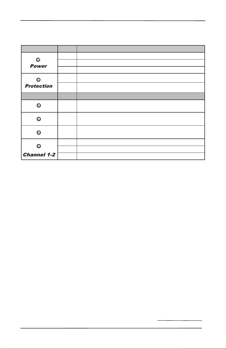
LED Function Table
LED Function Table
LED Color Description
Red The unit is in standby mode
Blue The unit is on
O The unit is powered o
Red The unit has detected a fault and is in protect mode*
O The unit is operating normally, or it is powered o
ZONE LEDs Color Description
Blue -10 dBFS zone output level
Blue -20 dBFS zone output level
Blue -33 dBFS zone output level
Red The zone has detected a fault, and is in protect mode
Blue The zone is active
O The zone is in standby
*The protection LED also comes on for a short time during power up or down
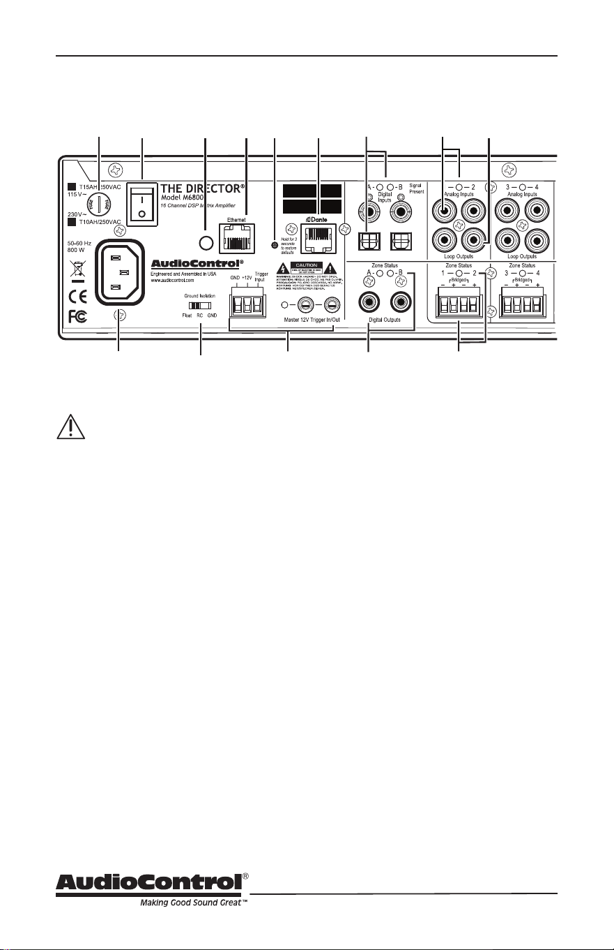
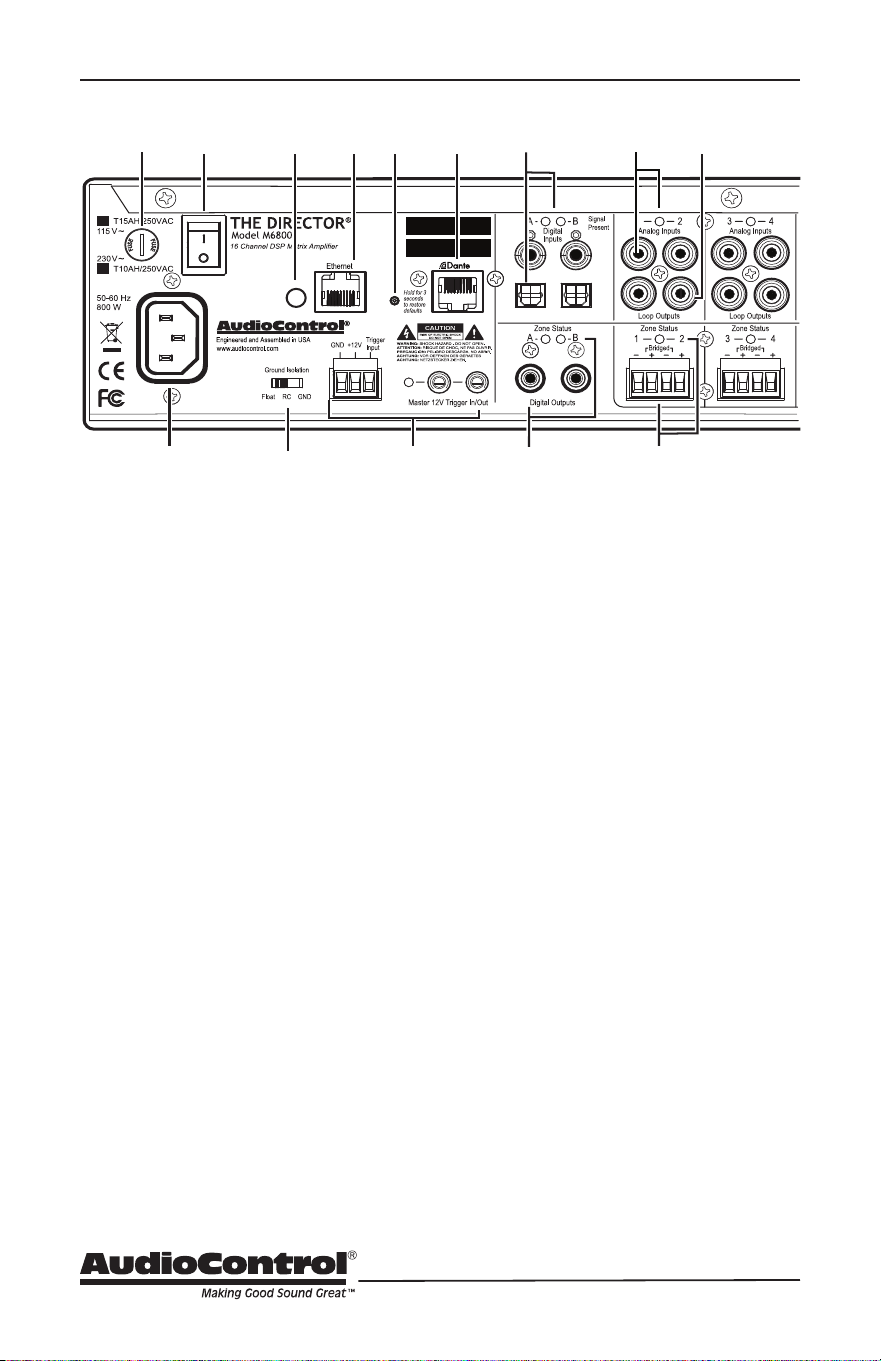
16
Rear Panel
Rear Panel Features
AC section
When rack-mounting the unit,
make sure that the power cord
and the AC power switch remain
readily accessible.
1. AC Input
Connect the supplied AC power cord
securely to this input. Plug the other
end into an AC mains outlet of the
correct voltage rating for your unit.
They are either 100 -120 VAC (50 – 60
Hz) or 220 – 240 VAC (50 – 60 Hz).
A checked box designates the unit
conguration and it is not user-
settable.
2. AC Fuse
The main power supply fuse may
be checked or replaced. Before
attempting to undo the fuse carrier
from the holder, remove the power
cord from the AC mains. The carrier
may be backed out of the holder by
carefully placing the tip of a at-head
screwdriver into the slot on the carrier,
and slowly turning anti-clockwise.
Inspect the fuse for failure, and if
required, replace it with the exact
same type indicated on the unit. The
use of a fuse with a dierent amperage
or voltage rating may lead to an
unsafe condition. Upon replacement, if
the new fuse subsequently fails when
power is applied to the unit, move the
power cord and contact AudioControl
customer service. Do not open up
the unit – there are no Internal user-
serviceable parts, and dangerous
voltages remain present for a duration
after the AC mains power has been
removed.
3. AC Power Switch
This switch shuts o the main AC
power. This may only be required to
be turned o when the system will be
shut down for an extended period of
time. Operational Ethernet commands
or the master trigger inputs are
used for switching the unit between
standby and on.
Disable front panel
LED ladders
Master
Reset
MAC
Address
Serial
Number
D
1
2 3
4
5
6
7
8
9
10
11
12 13
14

17
Installation Manual
Model M6800D
THE DIRECTOR
™
Rear Panel
4. Ground Isolation Switch
This switch selects the level of
isolation between the audio signal
ground and the AC earth ground.
The factory default position is GND
and should be used during regular
operation. Two other settings are
available to combat AC mains
noise. The RC (Resistor Capacitor)
setting is designed to address high-
frequency noise. High-frequency
noise components see the capacitor’s
connection to ground and follow this
low-impedance path. The FLOAT
setting is eective in eliminating
ground loops. For safety, the chassis
is always connected to the earth’s
ground regardless of the switch
setting. NEVER use three-prong/
two-prong adapters, commonly called
‘cheater plugs’, to connect this unit
to a NEMA 1-15R non-grounding
receptacle. These are seldom used
as intended, with the grounding tab
attached to the outlet faceplate screw,
which itself should be connected to
the electrical ground. A fault can send
high current through the chassis, all
connected cables, and outward. This
unit is a class 1 device, NEVER remove
the grounding lug from a NEMA
5-15P power cord for use in a two-
prong NEMA 1-15R non-grounding
receptacle. NEMA 5-15P plugs rely
on the grounding pin for proper
orientation. Removal risks insertion
into the outlet with neutral and hot
wires reversed, creating an additional
hazard.
5. Disable Front Panel LED Ladders
The front panel LED ladders indicate
output levels in active zones. To
disable the display, depress this
switch. (Do this instead of cutting the
red wire). Power, Protection or Zone
Status LEDs will remain functioning.
6. Ethernet LAN Port
This port connects The M6800D to
a 10BaseT network via CAT5e-CAT6
cabling, enabling control by the
internal Web Interface, accessible
through a standard web browser. The
M6800D does not require internal
software for operation. See the section
on Internet Connectivity and Control
for detailed information.
7. Master Reset
Should the M6800D fail to
communicate, pressing and holding
this button for more than 3 seconds
performs a reset of the internal
Ethernet settings. WARNING: Never
perform this function while turning on
the AC power switch. All ash memory
will be erased. If this has occurred,
contact technical support for the latest
rmware le.
8. Dante Port
Connecting this RJ45 port to a
network switch supporting Dante
audio streams allows the Director
to decode network information into
uncompressed audio signals. Now that
you have heard this information this
message will self-destruct in 10, 9,
8, 7, 6……..
18
9. Master Trigger
There are three methods to turn on
the unit or to place it into standby
mode: via Ethernet, the TS 1/8” mono
Master 12V Trigger input jacks, and the
3-pin block connector. AudioControl
products with 12V trigger outputs may
be used to pass on trigger commands
to The Director M6800D when they
power on, and the 12V master trigger
out on this unit will do likewise. If
Ethernet is not used to power on
the M6800D and no trigger voltage
is present at any trigger input, the
unit will be in standby mode and all
zones will be muted. To the left of the
master 12V trigger in/out jacks is an
LED indicator that will illuminate blue
when this input is active, and o when
no voltage is being applied. See Page
21 for more information on triggering
details.
Digital Inputs/Outputs
10. Digital Inputs
A and B digital inputs are RCA S/PDIF
coaxial and TOSLINK optical. Digital
signal data inputs directly into the
Disable front panel
LED ladders
Master
Reset
MAC
Address
Serial
Number
D
1
2 3
4
5
6
7
8
9
10
11
12 13
14
Rear Panel
M6800D advanced DSP section for
processing and is then made available
to any or all zones, selectable using
the M6800D web page interface. The
Signal Present LEDs illuminate when
a digital signal is present at the A or
B inputs. As mentioned previously,
use RCA-type cables designed for the
impedance and high-frequencies of
digital audio.
11. Digital Outputs
These S/PDIF digital outputs use
standard 75 Ohm RCA coaxial
connectors.
Digital signals from each of these
outputs can be copied from any zone’s
input pair, (converted internally from
analog to digital), or copied from the
A or B digital inputs. These options
are selectable using the M6800D
web page interface. As an example,
a copied output may be passed to
additional M6800D, Architect, CM,
Director, or Rialto series ampliers.
A Zone Status LED will illuminate to
signify the digital output is active.
19
Installation Manual
Model M6800D
THE DIRECTOR
™
Zone Section
(All details are the same for each zone)
12. Analog Inputs
These are line-level, single-ended,
RCA analog inputs for legacy sources
such as CD players, tape machines, or
stand-alone AM/FM tuners. Using the
M6800D web page interface menus,
any zone may be congured for play
as zone-specic, in mixed zones, or
all zones simultaneously. No man
to man coverage here. Additionally,
these signals are also made available
to the digital outputs for unparalleled
exibility. The LED illuminates when
an analog signal is detected at the
input.
13. Loop Outputs
Analog signals from the inputs above
are directly looped through these line-
level analog RCA outputs to additional
M6800D, Architect, CM, Director, or
Rialto series ampliers.
Speaker Connections
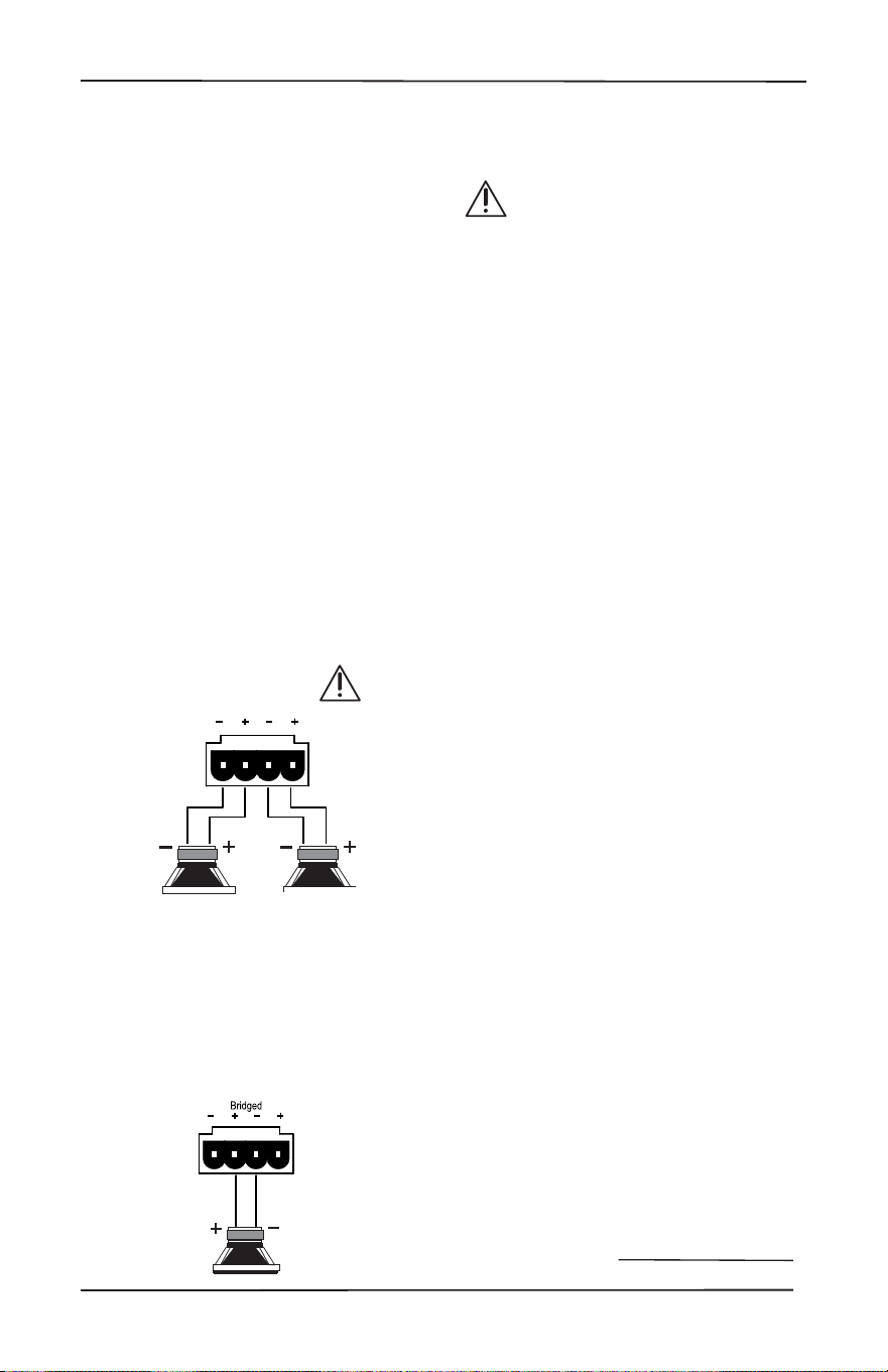
14. Speaker Outputs
This 4-pin connector allows easy
connection of two speakers for stereo
operation, or one speaker for bridged
mono operation.
Stereo Speaker Connection
Note the polarity markings for
each pair of outputs.
The speaker impedance should be 4
Ohms minimum in stereo operation.
Bridged Mono Speaker Connection
Note the polarity markings of the inner
pair of connections. In this mode, the
input signals are combined in mono,
and the power from both channels
is combined to drive a single, more
powerful, speaker.
The speaker impedance should be
8 Ohms minimum in bridged mono
operation.
To set the output to be in mono,
use The Director’s Web Interface
Operation menu (the rst page that
shows up) and click on the Mono box
for this zone.
Speaker Wiring
Establish a standard speaker wire
color connection code and maintain
it. It is important to match amplier
polarity ( + / -) with speaker polarity.
On any speaker where the polarity
may become reversed, that speaker
will be out of phase with its paired
partner, and from all other speakers in
the same listening area. Bass response
is impacted, with woofers that are
out-of-phase working to cancel low-
frequency sound waves produced by
the speakers in phase.
See the next page for some handy
information about speaker and wiring
impedance.
Zone Section
20
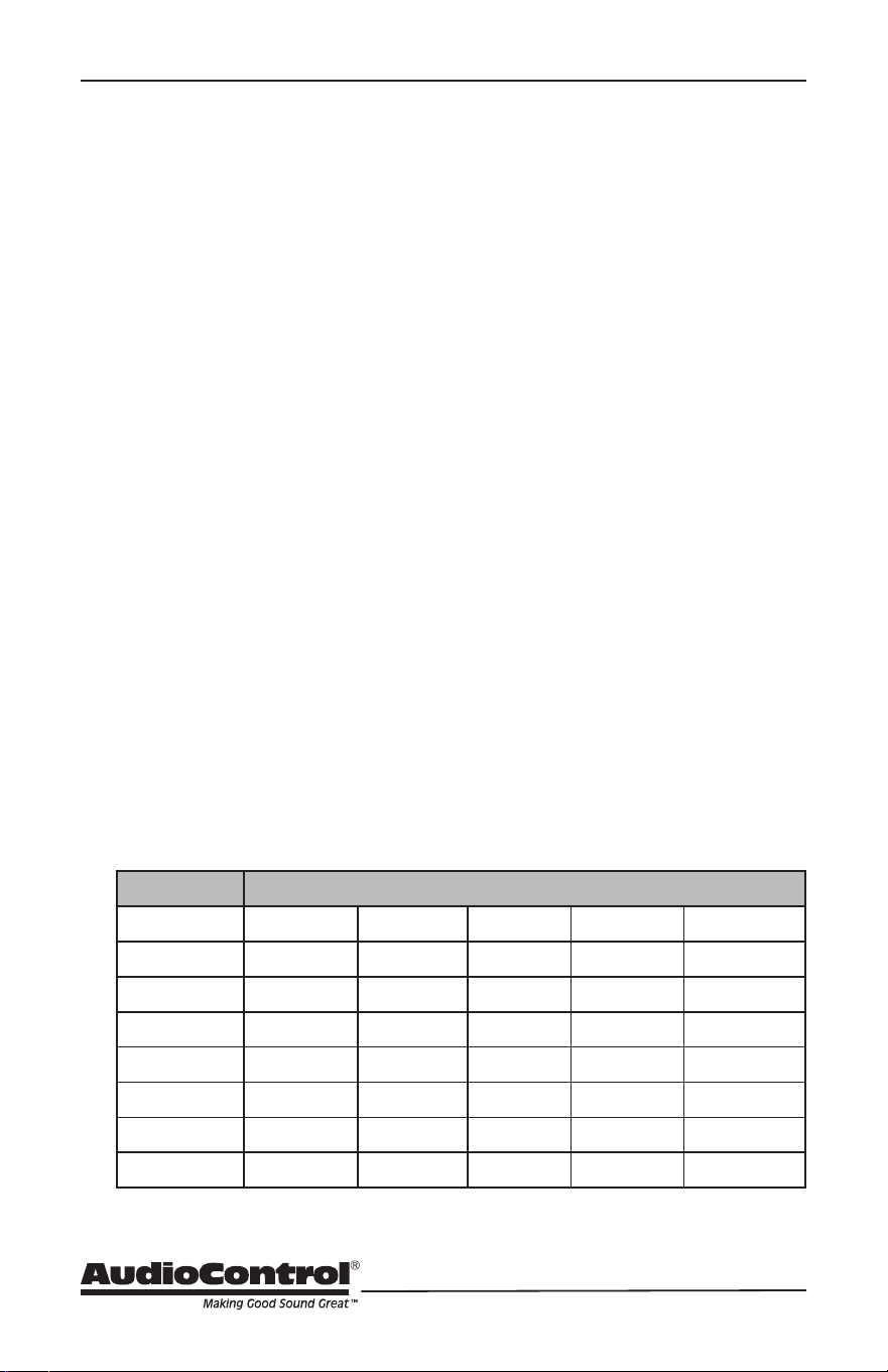
Speaker and Wiring Impedance
Wire Gauge Run Length
25’ 50’ 100’ 250’ 500’
24 GA 1.3Ω 2.6Ω 5.1Ω 12.8Ω 25.7Ω
22 GA 0.8Ω 1.6Ω 3.24Ω 8.1Ω 16.0Ω
20 GA 0.5Ω 1.0Ω 2.0Ω 5.0Ω 10.1Ω
18 GA 0.3Ω 0.6Ω 1.28Ω 3.2Ω 6.4Ω
16 GA 0.2Ω 0.4Ω 0.8Ω 2.0Ω 4.0Ω
14 GA 0.1Ω 0.25Ω 0.5Ω 1.26Ω 2.5Ω
12 GA 0.08Ω 0.16Ω 0.32Ω 0.8Ω 1.6Ω
Speaker Wire Resistance:
Wire Gauge versus Run Length
values in portions of their frequency
range, and speakers that are rated at
unusual impedances, for example, 3.5
Ohms.
The Director M6800D is tolerant of lower
impedance loads, and as a properly
designed amplier allows for some leeway
with impedance loading.
Speaker wire gauge combined with
the length of the run also contribute to
the speaker impedance load presented
to any amplier. As you can see in the
table below, even fairly short speaker
runs develop signicant resistance when
smaller wire gauges are used. This can be
a benet when a number of speakers are
wired in parallel. The wire itself acts as
an impedance limiter, since the amplier
cannot see a speaker load lower than
the resistance of the wire. The downside
to this form of wire resistance is that a
portion of the total available power to the
speakers is wasted.
Speaker and Wiring
Impedance
Speakers, like other resistors, when wired
in parallel “show” lower values than the
individual components. Here are two
examples for calculating speakers wired in
parallel:
Calculating Impedance
For three 8 Ohm speakers wired in
parallel (pluses connected to pluses)
the impedance is 1/8 + 1/8 + 1/8 = 3/8
Then take the inverse or 8/3 = 2.66 Ω
For two 8 Ohm speakers wired in
parallel (pluses connected to pluses)
the impedance is 1/8 + 1/8 = 2/8
Then take the inverse or 8/2 = 4 Ω
Often the real world is more complicated
than theory, and for speakers this is the
case. An eight Ohm speaker is not eight
Ohms at all frequencies. Plus passive
crossover networks add their own
changing conditions. Be aware of speakers
that have signicant dips from “nominal”
21
Installation Manual
Model M6800D
THE DIRECTOR
™
12 Volt Trigger Ins and Outs
12 Volt Trigger Ins and Outs
There are ve ways The Director M6800D may be awakened from standby for
operation, and to trigger additional M6800D units or other components. The table
below provides details for this exibility:
* +12 volts on tip, mono jack
The following details apply if the
Ethernet Web Interface will not be used
to turn on The Director M6800D.
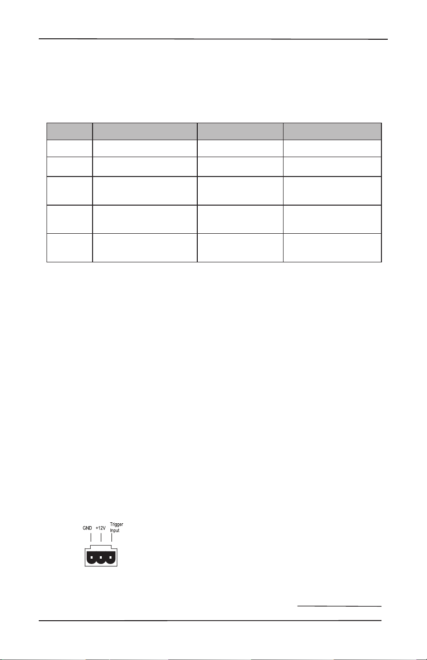
3-pin Connector
To remotely turn on the unit, use either
a contact closure between the Trigger
Input and the +12V output, or an external
+12V trigger between the Trigger In and
GND terminals. DO NOT attempt to use
this +12V output to power on additional
equipment as it is not designed to do so.
Pinout:
GND Ground
+12V Output
+12V Trigger Input
1/8” TS mono jacks
These are wired in parallel to each other,
and work in conjunction with the 3-pin
connector. Both jacks may function as
inputs or outputs. Either jack can receive
a +12V trigger as an input, which will
turn on the unit. The second jack is then
available and functions as a +12V output
that may be used to turn-on a second
unit. If the 3-pin connector is used to
trigger the unit, then both of the 1/8”
jacks may be used as output triggers for
other units.
Pinout:
Tip = +12V Trigger Input
Sleeve = Ground
Method How
Triggered
LED
Indicator Mini Jacks Powered*
1 Ethernet Ethernet Triggered No
2 12 volt mini plug
input* 12 v Trigger Active Yes, unused jack
3 Jumped Phoenix
connector
12 v Trigger Active Yes
4
Contact closure on
Phoenix connector
12 v Trigger Active Yes
5
12 volt input on
Phoenix
connector
12 v Trigger Active Yes

22
Power Up Process
When +3 to +12V is sensed by either of
the 1/8” TS mono connectors, or at the
3-pin connector, as an input trigger signal,
the rear panel master trigger indicator
LED changes from o to illuminate
blue. All zones remain in standby for
approximately 2 seconds until the
power supplies have fully charged and
completed self-diagnostic testing. During
this short interval, the front panel Power
and Protection LEDs remain red. Once
this process has been completed, the
Power LED will illuminate blue and the
Protection LED will turn o.
Power Down Process
When 0Volts is sensed at the master
trigger inputs, all zones are muted and
placed into standby, and the rear panel
master trigger LED will change from blue
to o. The front panel Power LED will
remain on, as the main power supplies
remain energized. When the master
trigger Inputs have sensed 0Volts for at
least 2 seconds, the main power supplies
will shut o and the front panel Power
LED will change its status from blue to
red. The Protection LED will ash red
once during the power-down process. The
trigger input is biased toward ground.
This keeps the unit in standby when
nothing is connected. If triggering is not
performed using the master trigger of the
Ethernet connection, a short wire linking
the +12V output to the trigger input must
be installed. To return the unit to standby,
simply remove the link.
Wire Link
To trigger ON with a contact closure
Connect the contact closure between
+12V and the Trigger Input
To trigger OFF with a contact closure
Connect a 1 kΩ resistor between +12V
and Trigger Input
Connect the contact closure between
the Trigger Input and GND
To use an external 12V trigger
Connect the external ground to the
Director M6800D GND
Connect the external +12V output
volt¬age to the Director M6800D
Trigger Input
12 Volt Trigger Power Up and Down
23
Installation Manual
Model M6800D
THE DIRECTOR
™
Ventilation
Ventilation
The Director M6800D features cool-
running, ecient switch mode power
supplies and Class D ampliers, equipped
with thermally controlled fans. As
high-powered 16-channel ampliers,
proper ventilation is required to maintain
suciently cool operational status.
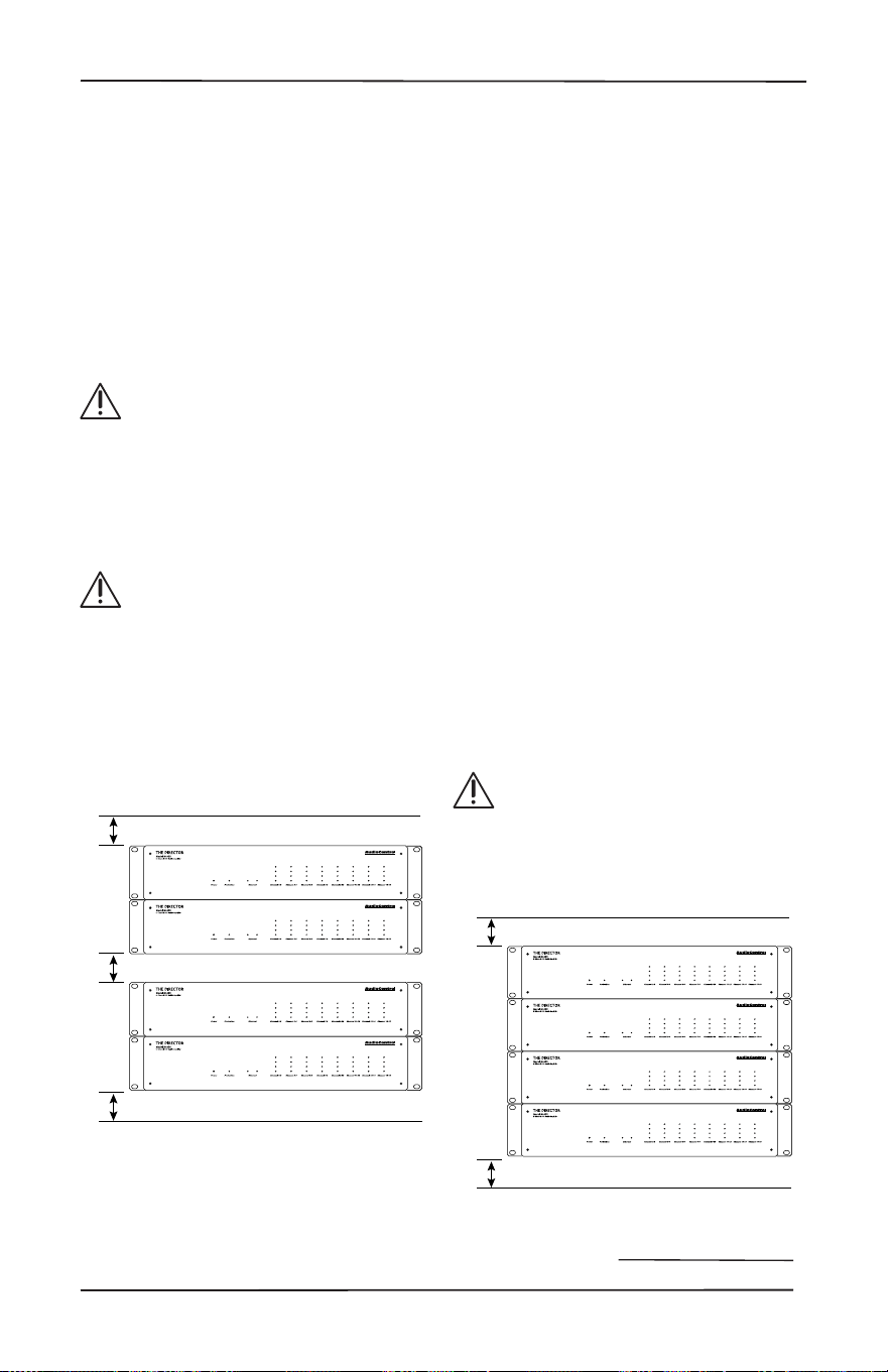
Please be advised that no more
than 4 Director models may be
stacked together. Any more than
that, then a rack space above and
below is required for adequate
ventilation.
Review the heat load specications
and ensure that your rack room
meets these requirements.
If the amplier should happen to overheat,
a thermal sensor places it into standby
mode, enabling the heatsink to cool down.
Once the amplier has attained a safe
operating temperature, it will reactivate.
If this occurs often, the cause must be
identied and corrective action taken.
This may include:
• Additional ventilation
• Ensure the installation location does
not have limited or no airow
• Install heat extraction fans in the
rack, or the installation location
• Determine if the ampliers are
overloaded by speaker impedances
below the recommended minimum
• Inspect speaker cables and speakers
for signs of short-circuiting.
Note: Zones shut o independently when
a fault such as a short circuit is detected.
1U
1U
Ideal Spacing 1U rack space or more
above and below each pair
1U
1U
1U
No more than four units can be stacked
without a rack space between them.
Allow 1U rack space or more above and
below each stack of four.

24
Internet Connectivity and Control
Setting up The Director M6800D for Ethernet control is eortless. Simply connect it
to the network it will reside on and allow the DHCP server to assign the M6800D an IP
address. Take note of the unit’s MAC address on the chassis rear adjacent to the model
name and serial number. Write down or use a phone camera to capture it for reference.
After the M6800D has acquired an IP address from the DHCP server (this may take a
few seconds), scan for this address on the network. Enter the address into a browser
and the M6800D Operations page will open up.
Other than connecting to the browser for initial setup, conguration, and EQ settings,
the M6800D may be controlled via Telnet, through Telnet port.
Internet Connectivity and Control

25
Installation Manual
Model M6800D
THE DIRECTOR
™
Control Using a Browser
Microsoft operating systems
Connection to the M6800D for setup or
control can be made over a network or
directly. One way is to simply connect
over a network with a DHCP server via the
Ethernet port on the M6800D and allow
the unit to obtain a local address. Zip
code is not needed. If a direct connection
to the M6800D is preferred, make a
connection between the two devices
with an Ethernet cable. The connected
computer will require a static IP address,
with 192.168.0.249 the default address of
the M6800D.
With a Windows-based computer, change
the computer IP address to a static
address of 192.168.0.x – where x is a value
between 1 through 254, but do not use
249. Verify the static address selected
is not in use by another device on the
network, unless you want to start the War
of the Worlds.
Important Note
The Director M6800D initially defaults to
DHCP. If a DCHP server is not found, the
M6800D will subsequently default to an
IP address of 192.168.0.249. If DHCP will
not be used and a static IP address will
be assigned, provide the M6800D an IP
address rst via direct connection with
the computer. Never allow two devices to
share an IP address on the same network.
Internet Connectivity and Control
Apple/Mac Desktops and Laptops
Direct connection is the easiest method
for connecting the M6800D with Apple
computers. The default IP address of
the M6800D is 192.168.0.249 which will
require the Apple computer to have a
static IP address.
Provide the Apple computer with a static
IP address of 192.168.0.x – where x is a
value between 1 through 254, but do not
use 249. Verify the static address selected
is not in use by another device on the
network.
Communications Options
The M6800D’s web server “Device
Conguration” page contains many
communication options.
Here are a few notes
Server Gateway must be specied in order
to access the SNTP time server. DNS must
be specied as well for the SNTP and
SMTP functions to work – 8.8.8.8 (Default)
or 8.8.4.4 are public DNS servers Google
has enabled for use.

26
Control via Telnet
Commands
Controlling the M6800D in an automation
network requires system management
that can send and receive telnet
commands and responses.
The command and response structures
of the controls provided via telnet are
in simple human language. Power On is
simply “power1” followed by a carriage
return to end the command. Command
feedback is conrmed by an echo of the
command, followed by a carriage return,
then another statement of “01”followed
by the command string, then a carriage
return and a line feed to end the response
string. If there is a value-change like
volume up, then the conrmation
response will include the new value at the
end of the string.
Telnet Session Length
Sending the M6800D a command opens
a telnet session – simply send a command
and a response follows. A session will
remain open for 4 hours, and then close
(enough time to nish Gone With the
Wind). If another command is received
within that 4 hours, the session clock
restarts. The session will close 4 hours
from the time of the last command
received (about the same length as your
co-workers stories). If the automation
system being used considers this type of
activity as the M6800D dropping o the
network, a good practice may be to set up
a periodic ping query.
Control Command Examples
Increment volume by 1, in Zone 3, where
volume before the command is 51:
Command: Z3vol+<CR>
Response: Z3vol+<CR>
01Z3vol52<CR><LF>
To turn on main power:
Command: power1<CR>
Response: power1<CR>
01power1<CR><LF>
To mute or turn Zone 5 o:
Command: Z5o<CR>
Response: Z5o<CR>
01Z5o<CR><LF>
Note:
The query ZONEON? returns a description
of the on state of all the zones, where
each zone is separated by a space.
1 equals on, and 0 equals o. So if zones
6 and 7 are on and all the other zones
are o the information will be displayed
like: 0 0 0 0 0 1 1 0 0 0. Also note that the
last two values in position 9 and 10 are
reecting the state of the digital outputs.
The response to the query ZONEOFF?
will return the opposite values if zones 6
and 7 are o as it is conrming that the
zones are o so that value is positive:
1 1 1 1 1 0 0 1 1 1.
Please visit our website for additional
information and a table of control
commands:
www.audiocontrolpro.com/director-
model-m6800d.html
*As things in the fast-paced world of
technical documentation are constantly
changing, visiting our website is one way to
make sure you have the latest information.
Control via Telnet Commands
27
Installation Manual
Model M6800D
THE DIRECTOR
™
Web Interface
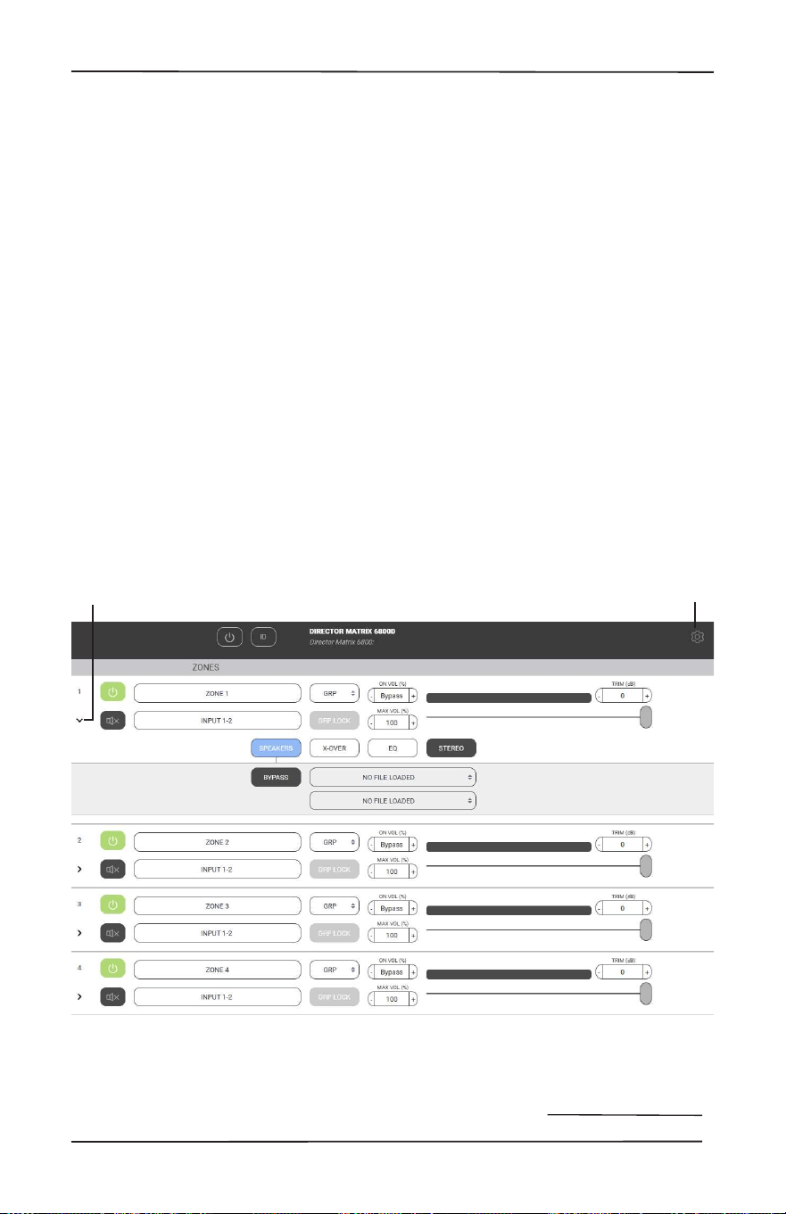
Set up via the Web Page
Enter the IP address of the unit on
any device that supports browser use.
The web page is responsive - meaning
that it will auto-size to t the device
screen size. When using a small
phone, the layout adjusts to that size
and will also be touch-sensitive. On
a computer, the web page will adapt
to the browser size. Conguration for
all the parameters of The Director is
made through this interface. The initial
view of the web page shown below
illustrates the current state of the unit.
To access global settings, click on
the “gear” icon at the top right of the
page. To change zone settings, click
on the caret (the “v” icon) to expand
the selections. Simply clicking on an
option will expand the adjustable
parameters. These conguration
options allow customization to The
Director’s performance to match any
system design.
Clicking the caret expands
the menu options for each
Zone or Digital Input
The gear icon opens
and closes the global
settings menu
28
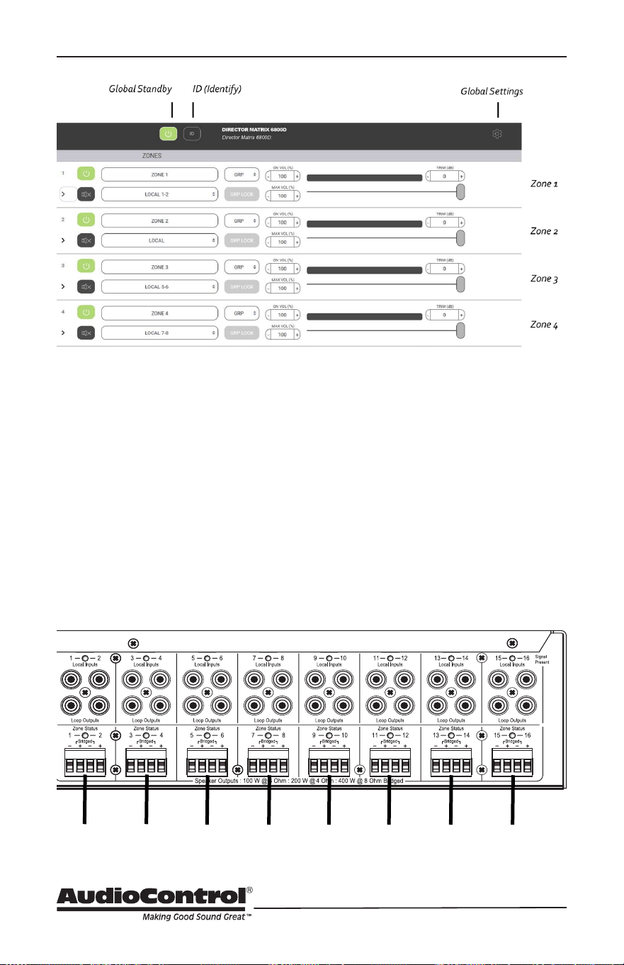
Set up via the Web Page
Global Standby
This is basically a main power-o
where the amp, power supply and
DSP are shut down. Power up from
this state is about 10 seconds.
ID
Pressing this button will cause the two
ethernet lights to ash in tandem on
the front of the unit. This is useful if
there are multiple units in operation,
and you want to make sure you are
adjusting the right one.
Global Settings
Expand this panel for additional
controls. See page 32 for more details.
Zones 1-8
The settings in each section denes
the rear panel speaker-level output to
each of these 8 zones.
...
Zone 1 Zone 2 Zone 3 Zone 4
Zone 5
Zone 6 Zone 7 Zone 8
29
Installation Manual
Model M6800D
THE DIRECTOR
™
Zone Settings
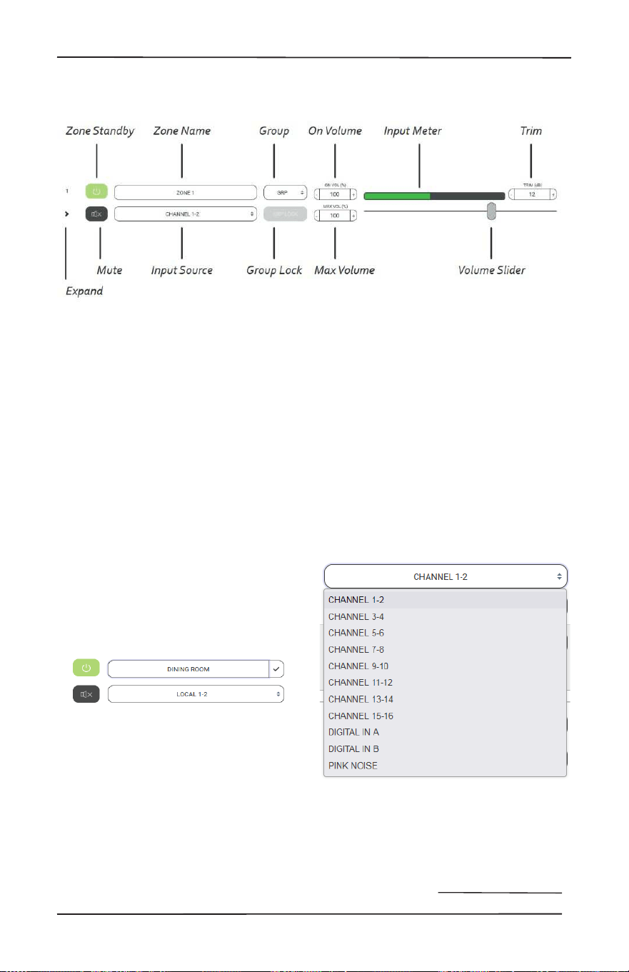
Zone Settings
Zone Standby
Turns only the associated zone
amplier on or o to enable virtually
instantaneous output when the zone is
activated. In less than 500ms, the zone
swings from standby to on. Boot-up
time is eliminated.
NOTE: When set for Signal Sense, both
Global On and Zone On should be set
to respond to signal input.
Zone Name
Zone names can be changed by
typing in this box. When a new name
is entered, select the check box to
the right to save all changes. Up to
30 character spaces are available for
custom naming.
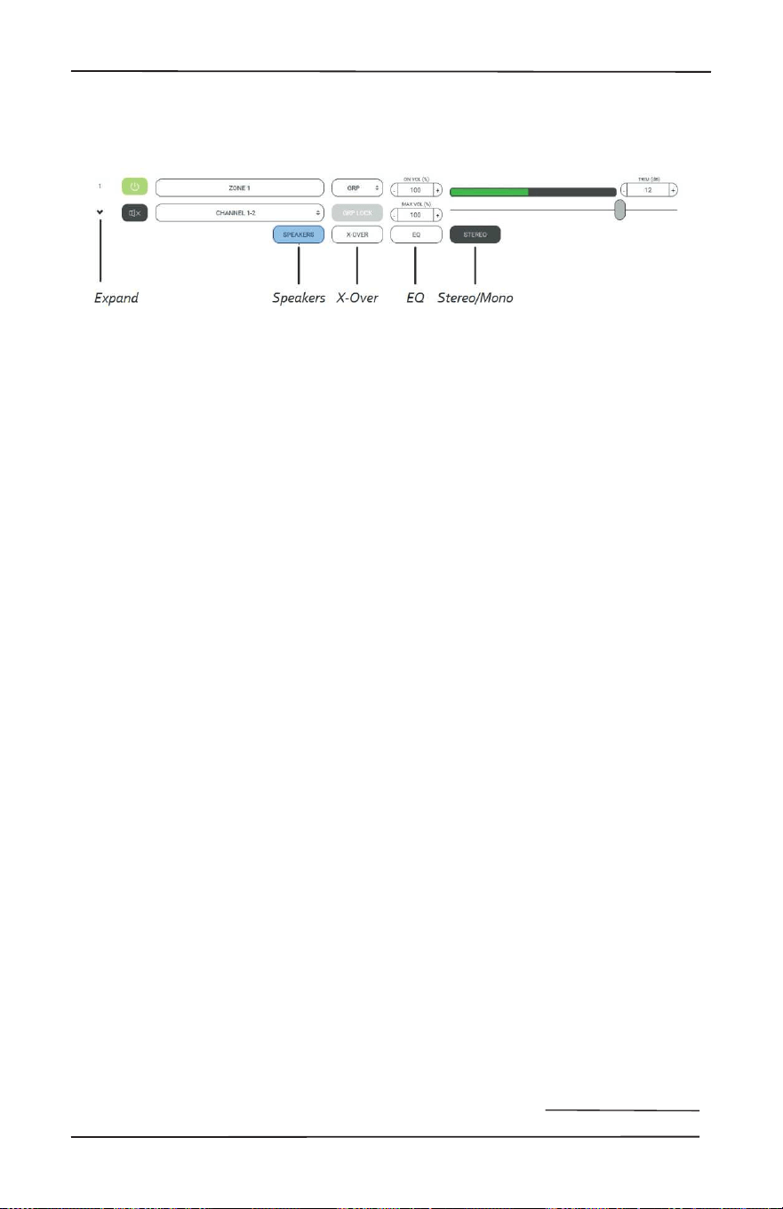
Expand
Select for more options in this zone.
Mute
Select to quickly mute or unmute the
output from this zone.
*mute* “Maaaa, Meatloaf” *unmute*
Input Source
Select the input source that will play
in the zone. Pink Noise is available
to assist with volume settings and
acoustic calibration in each zone.
The name of each input source can be
changed using the Global Settings/
Input Sources menu and the changes
(when saved) will appear here.
Zones that are assigned to the same
group may share any input, including
Dante sources.
30
Zone Settings
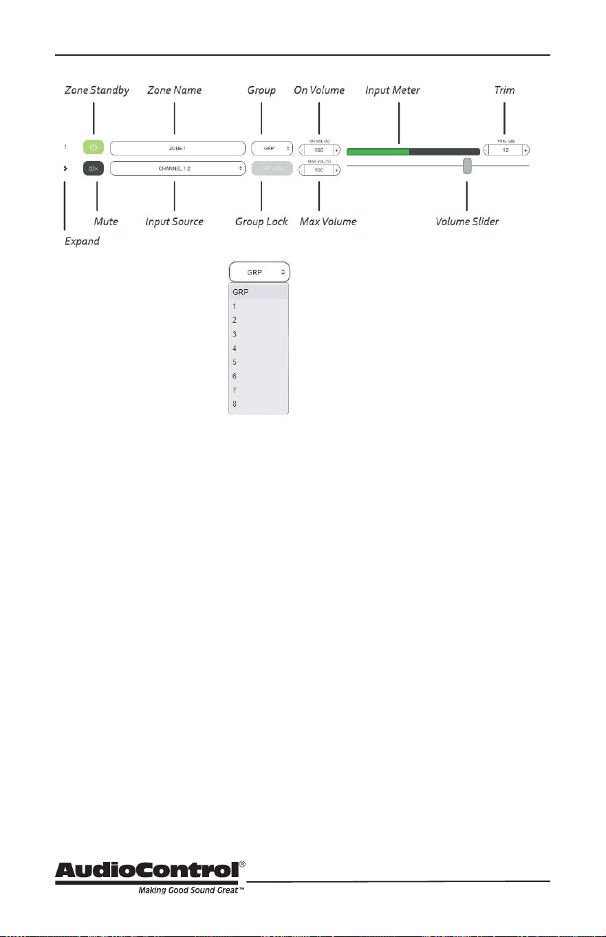
Group
Each zone may be
assigned to a group in
the drop-down menu.
Select a group for a
particular zone to belong
in, from 1 to 8, or allow it
to remain on GRP if this
feature is not being used.
Group Lock
If the zone is assigned to a group,
select to activate this function.
When Group Lock is selected, the
following message appears:
“Proceeding will set the volume of
all the zones in the group (that also
have group lock engaged) to the
minimum of them.”
The feature works as follows: If Zones
1, 2 and 3 are to be assigned as Group
1, select Group Lock for each one of
these zones. Each Group Lock button
will turn to orange when selected.
When this sequence has been
completed, the volume level for all
zones in the group will adjust to match
the zone with the lowest level when
the group was assembled. A change
in volume to any zone in the group
collectively changes the group volume.
If the input source is changed to a Bus
input, all zones in the group will follow.
On Volume
Sets the zone volume to a specied
startup value. If the volume in the
zone was higher prior to the new value
change, the new selection becomes
the default.
Max Volume
Sets the maximum volume level of the
zone.
Input Meter
Provides a graphic depiction of the
incoming signal level.
Volume Slider
Primary volume adjustment in a zone.
Trim
Enables ne-tuning for zone volume.
This is particularly useful when
multiple zones are grouped into a
single listening area. An example
might be 3 speaker pairs, individually
zoned, that provide audio for a large
Living Room. Equalization may
inadvertently accentuate one pair
creating the impression they are
louder. Trim can assist with acoustic
balancing in the area. Trim interacts
with the Volume Slider to establish an
overall peak threshold in zones where
end-user control may inadvertently
chance speaker damage. Input levels
may be set using the Global Settings/
Input Sources menu.
31
Installation Manual
Model M6800D
THE DIRECTOR
™
Zone Options
Zone Options
Speakers
This is where speaker proles are
accessed. Speaker proles contain
optimized settings that select speaker
manufacturers have compiled
to maximize the performance of
their models when powered by the
M6800D.
X-OVER
This enables access to the Low Pass,
Band Pass, and High Pass crossover
lters to control the frequency ranges
the M6800D sends to speakers.
EQ
Enables access to the graphic and
parametric EQ lters to precisely
match speakers to the acoustic
environment they operate in.
STEREO/MONO
Output may be set for mono
playback or stereo.
32
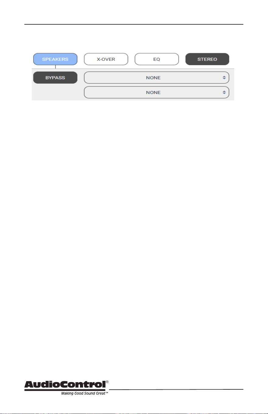
Speakers
Speaker Calibration Prole
Speaker Proles contain equalization
and crossover settings that have
been carefully selected by certain
speaker manufacturers to be the
ideal performance metrics for their
particular speaker model. The prole,
when selected, is applied in the
background and not illustrated by the
M6800D GUI. With speaker proles
applied, graphic EQ adjustments
may still be made to ne-tune the
speaker’s response in the room, and/
or to accommodate client preferences.
Each zone may be assigned a dierent
prole, to accommodate dierent
speaker models.
Speakers
NOTE: Speaker proles are not
pre-loaded as standard presets on
the M6800D. They are available for
download from the AudioControl
website.
Available speaker proles are updated
regularly. Please check our website for
the latest additions.
33
Installation Manual
Model M6800D
THE DIRECTOR
™
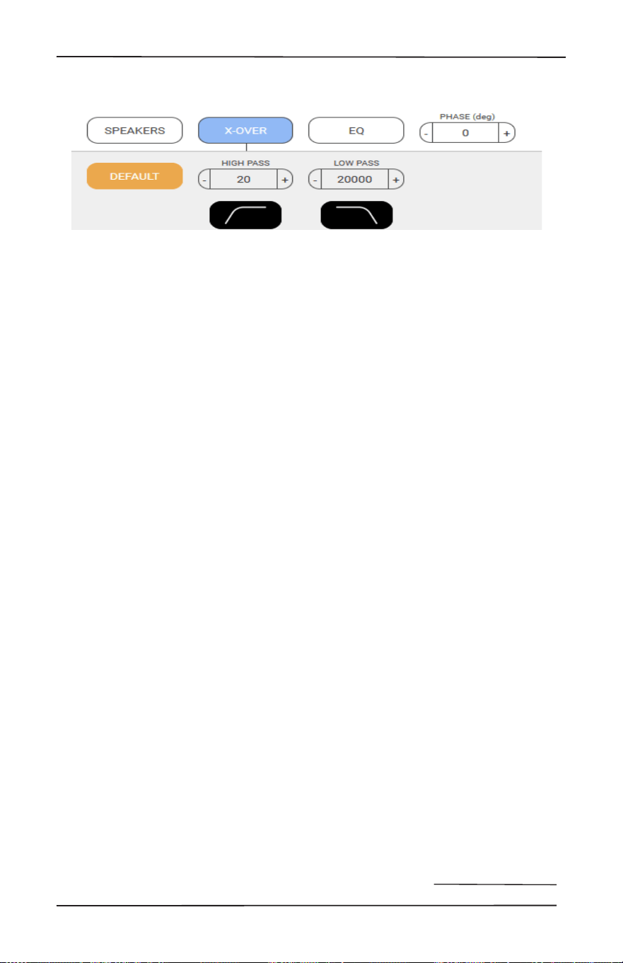
X-Over
Here you can adjust the range of
frequencies that play through the
selected output. Each box allows you
to type in the desired frequencies or
you can adjust with the +/- buttons for
a Kubrikian level of detail. The high
pass lter can be set between 20-
15000Hz, and the low pass between
30-20000Hz. Pressing the Default
button returns the crossover to it’s
default full range setting, and the non
interactive icons below help illustrate
how the highpass and lowpass
features work.
To prevent stressing woofers from
frequencies lower than they are
designed to safely handle physically,
use the subsonic lter. For inwall
speakers in relatively compact
footprints (not exotic oor to ceiling
inwall line arrays) we recommend a
setting near 40 Hz or higher. Contrary
to popular thinking, a higher setting
contributes to making this low
frequency lter sound better. Similarly,
for delicate tweeters, conservative
settings with the high-frequency lter
that protects tweeters could prevent
service calls. The M6800D is capable
of easily delivering vast amounts
of power to any type of speaker
(do not be fooled by the M6800D’s
lighter weight, Class D ampliers are
deceiving). A 2-way crossover can be
set up with a subwoofer dedicated to
the low end, and a pair of speakers
playing mids and highs. Enable the
Low Pass Mode lter, and bridge two
zone channels into a single, high-
powered mono subwoofer channel.
These combined channels will receive
only the low frequencies (monaurally).
Use two channels from another zone
to power a stereo pair of high-range
speakers with the High Pass mode
(like from Cheech to Chong) selected
for that zone.
X-Over
34
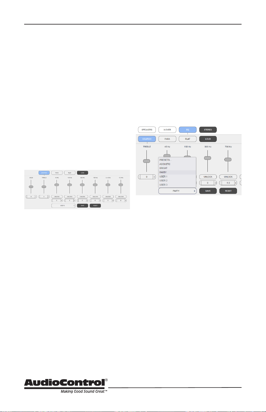
Graphic EQ
Use the graphic EQ to make
relatively broadband adjustments
to speaker interaction within a
selected zone. As both channels are
adjusted simultaneously, selecting
“UNLOCK” enables independent
channel adjustment. Changes are
made by selecting a parameter and
dragging the slider from its default
to the desired new position. Below
UNLOCK, there is another tab with a
value reading in the center and anked
on the sides with +/- adjustment
tabs. These are stepped versions of
the sliders. Note that the sliders or
the steps oer the ability to back
a particular frequency adjustment
down from its default position. A
hardsurfaced, reective room may
benet more from reducing acoustic
energy in a particular frequency band
than adding it to another.
A large tab at the bottom of this menu
accesses preset equalization settings,
including custom curves created and
saved. Select the adjacent SAVE tab to
store an EQ curve, or on the far right,
select RESET to restore defaults and
begin again.
Settings with various EQ curves
may be saved to the memories from
which end-users may select their
preferences.
BASS and TREBLE
The two sliders at the extreme left of
the graph are conventionally labeled
BASS and TREBLE. When adjusted
their eect is more global than other
tabs that are isolated to a regional
frequency range. BASS and TREBLE
may be referred to as Shelving EQ
adjustments, which boost or cut a
wide band of frequencies with equal
energy in the high-frequency range of
the spectrum or in the low-frequency
range, above or below a certain
frequency. Start with the graphic EQ at
“at” and slowly apply a bit of shelving
bass or treble EQ and determine if that
evens out speaker response for the
zone.
EQ Ramblin’s
A change to equalization settings
within a zone will aect both channels.
A later section of this manual
addresses the methods and benets
equalization oers acoustic spaces.
Equalization is a powerful tool,
however, it requires eort for accurate
results. Easily overdone, like lens ares
in an Abrams lm, misadjustment
may deliver a more poor-sounding
response curve than no adjustment
whatsoever. Available audio analysis
instrumentation will take the
guesswork out of successfully setting
the EQ for each zone.
EQ Ramblin / Graphic EQ / Bass and Treble
35
Installation Manual
Model M6800D
THE DIRECTOR
™
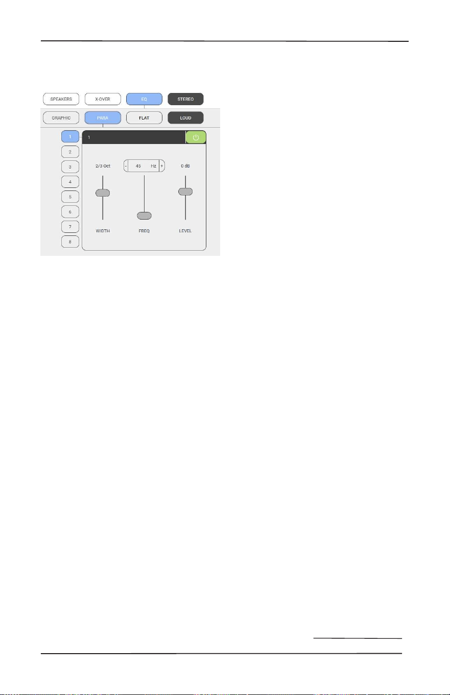
Parametric EQ / Stereo Mono / Loud
Parametric EQ
In addition to Graphic equalization,
there are 8 separate Parametric
equalizers per zone, for the ultimate
in room-acoustics problem-solving
(or perhaps, problem-creating). Each
parametric EQ has adjustments for
the octave width, frequency, and level
boost or cut. An example of use would
be detecting a room resonance where
a certain frequency induces an audible
vibration to a part of the structure or
to something located in the space. A
narrow-width lter can be crafted to
reduce the energy level in the signal at
the precise frequency point where the
resonance occurred. Once parametric
EQ settings are nalized, return to the
Graphic EQ menu and select SAVE.
Stereo/Mono
Select this tab to combine both
channels in a zone into mono. This
is useful when the channels are
bridged for a single speaker, such as
a subwoofer. It is also benecial in
large or outdoor zones where stereo
imaging is impractical or impossible.
One or two pairs of speakers
connected as normal (pay heed to
impedance) will play content so all
details are audible from any listening
position.
Loud
Select this tab to apply an equal
loudness curve to music. At lower
volume levels, the human ear is
less sensitive to the low and high
frequency extremes of the audible
spectrum compared to mid-range
frequencies, where hearing is more
acutely sensitive. At higher volume
levels, the response is perceived
as more “at”. To simulate this at
frequency balance for low listening
levels, the loudness circuit boosts low
frequencies and high frequencies,
leaving the middle range untouched.
36
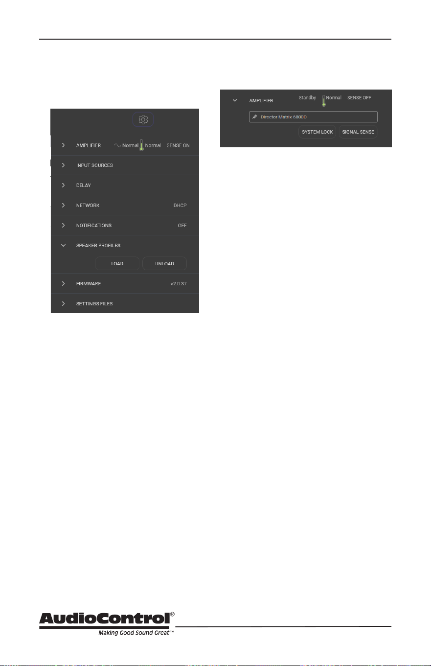
Global Settings: Amplier
Selecting the Gear Icon accesses
Global conguration options.
Global Settings
Amplier:
If desired, the unit may be renamed
by typing inside the box and then
selecting the check mark. AC mains
and thermal status may be monitored.
SIGNAL SENSE may be adjusted to
on or o by toggling the tab, with
the status displayed in the top right.
SYSTEM LOCK is also a toggle, but
to proceed requires that a system
password be entered. NOTE: Once
the system has been locked, control
over parameters is only possible by
entering the password. Retain the
password with all other critical project
data.
37
Installation Manual
Model M6800D
THE DIRECTOR
™
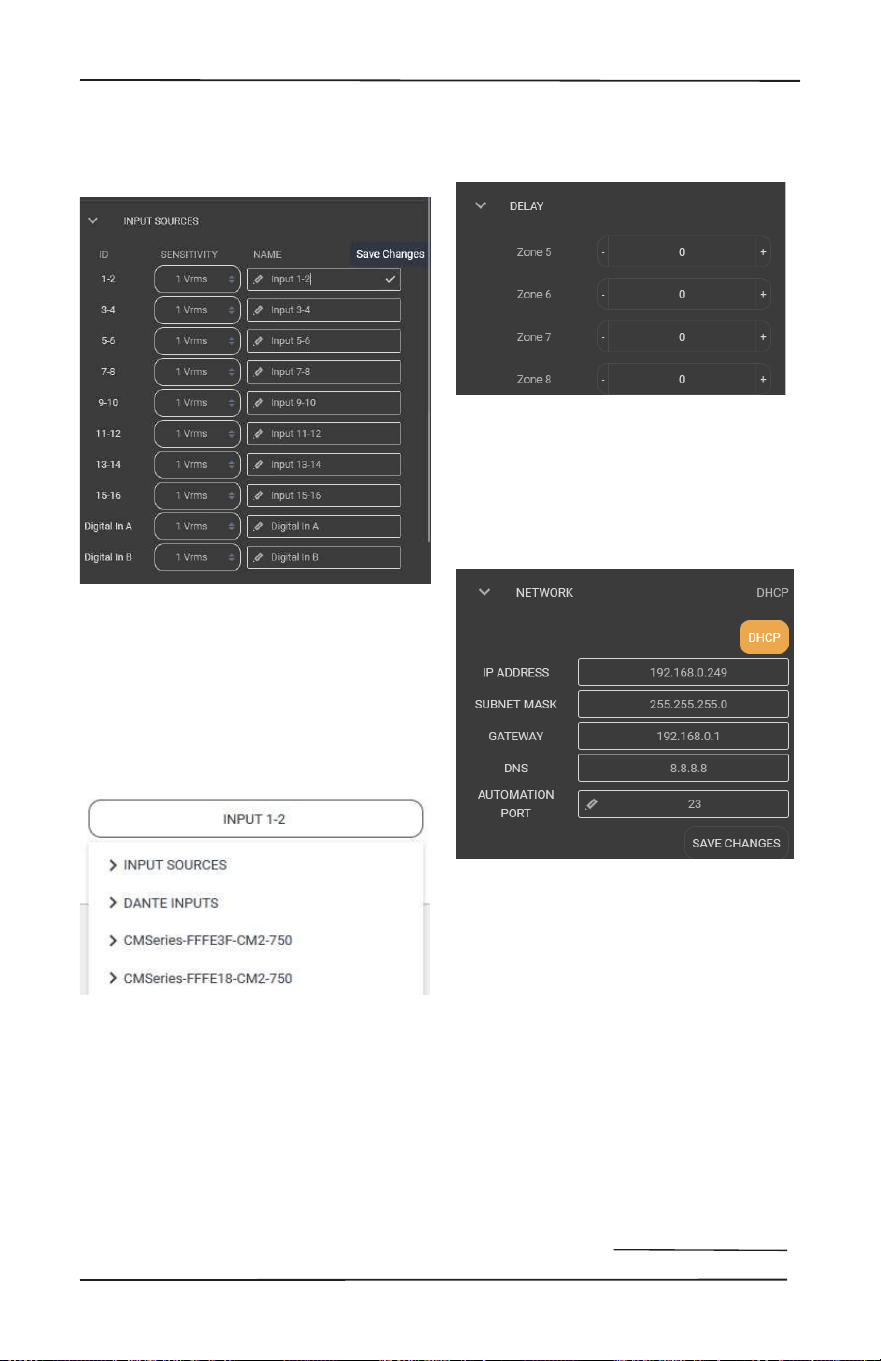
Global Sttings: Input Sources / Delay / Network
Delays between zones may be set in
5-millisecond increments to balance
audio across large areas.
Network:
Congure all network settings in this
menu when the M6800D is set up
manually. When set up is automatic,
ensure the DHCP button is selected.
The default IP address of the unit is
192.168.0.249. Manually connect peer
to peer for troubleshooting.
Delay:
Input Sources:
Sources may be custom-named. Type
inside the box, and when complete,
select the check mark at the right
in each box to save changes. NOTE:
Save after each change and before
proceeding to rename the next input
or changes will not be saved). New
names will appear in each Zone list.
There is an option to change input
voltage sensitivity. Common audio
source outputs range from 1V to
2V. 1.5rms may prove to be the best
setting.
38
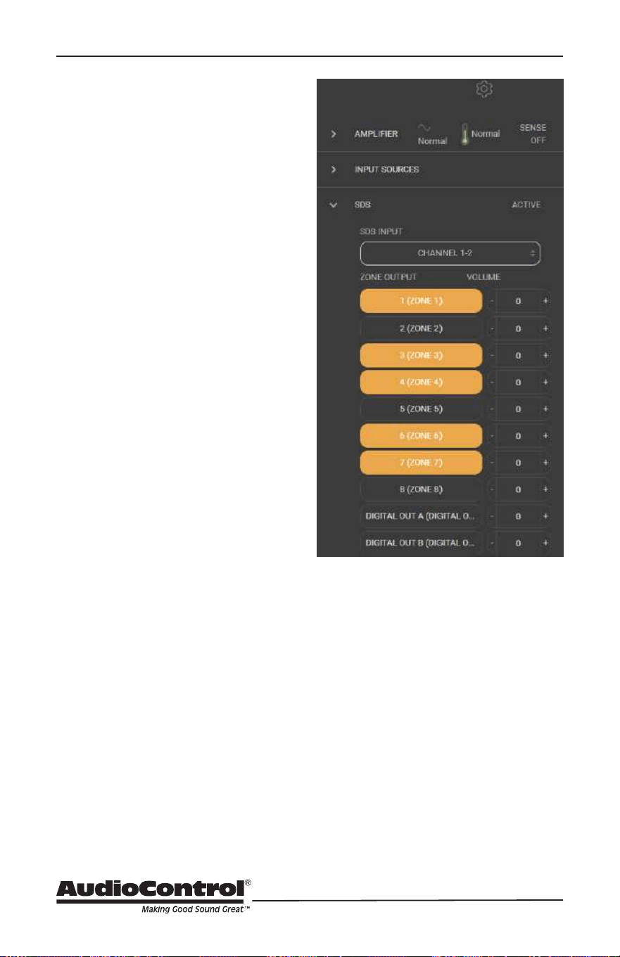
Signal Detecting Switching
SDS – Signal Detecting
Switching
A highly desirable integration feature
called Signal Detecting Switching, or
SDS is incorporated into the Director
Matrix series. SDS enables third-
party automation systems to route
door station audio, or any voice-
activated device, into the M6800D
for distribution through residential
or commercial audio systems. Any
input channel (or stereo pair) may be
congured as the designated SDS
input, while any or all zone outputs
may be selected as announcement
or paging zones. When an incoming
audio signal is detected at the SDS
input, audio present in assigned SDS
output zones is completely muted
until the announcement has been
completed, at which time previous
signals will resume playing.
Setting up Signal Detecting Switching
is accomplished easily and quickly.
• Using a computer connected to the
same network as the M6800D, enter
the amplier’s IP address into a web
browser. If the IP address is unknown,
use an IP scanner to search for the
amplier on the network.
• The menu will appear shown here:
• Once detected, log into the Web
Interface, select the gear icon in the
upper right corner, and open the
settings menu.
• Locate the SDS tab, and in the SDS
Input drop-down list, select the input
that will be assigned as the SDS
input. The input button will change
to orange.
• Select the Zone Outputs that will
operate for SDS, including the two
digital outputs.
• Volume levels for announcements are
adjustable in each SDS output zone.
39
Installation Manual
Model M6800D
THE DIRECTOR
™
Speaker Proler / Firmware / Setting Files
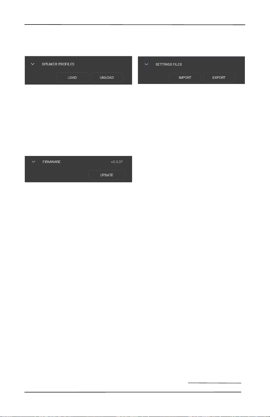
Settings Files:
All settings for The Director M6800D
may be backed up and exported.
Every parameter is stored into a single
external le.
NOTE: It is important to save each
zone’s conguration settings into a
user memory. Even if there are not
multiple recallable EQ memories,
it is still necessary that zone
congurations be saved in the event
of a total loss of power. The SAVE
function, in the Graphic EQ section
for each zone, saves the EQ for that
zone as user presets. The EXPORT
button functions as a global save for
settings in all zones. It is an overall
snapshot of all M6800D settings. All
Graphic, Parametric EQ settings, plus
any Crossover settings are retained in
the exported le. These settings may
be used for backup purposes, or as a
template for use in future projects.
Selecting the IMPORT
To load settings, select IMPORT, then
select an exported saved le that
contains current settings, or search for
a le with previously saved settings.
With all these Imports and Exports, it
makes me want to rip o my sleeves,
crack open a Corona and work on my
RX-7 or Skyline. Family.
Speaker Proles:
Speaker proles are not pre-
loaded. Proles for select speaker
models by our speaker partners
may be downloaded from www.
audiocontrolpro.com and uploaded
to the Director M6800D by using the
LOAD option.
Firmware:
Update rmware using this menu.
NOTE: Backup current SETTINGS
FILES and export before updating
rmware. Firmware les can be
downloaded from: audiocontrolpro.
com
40
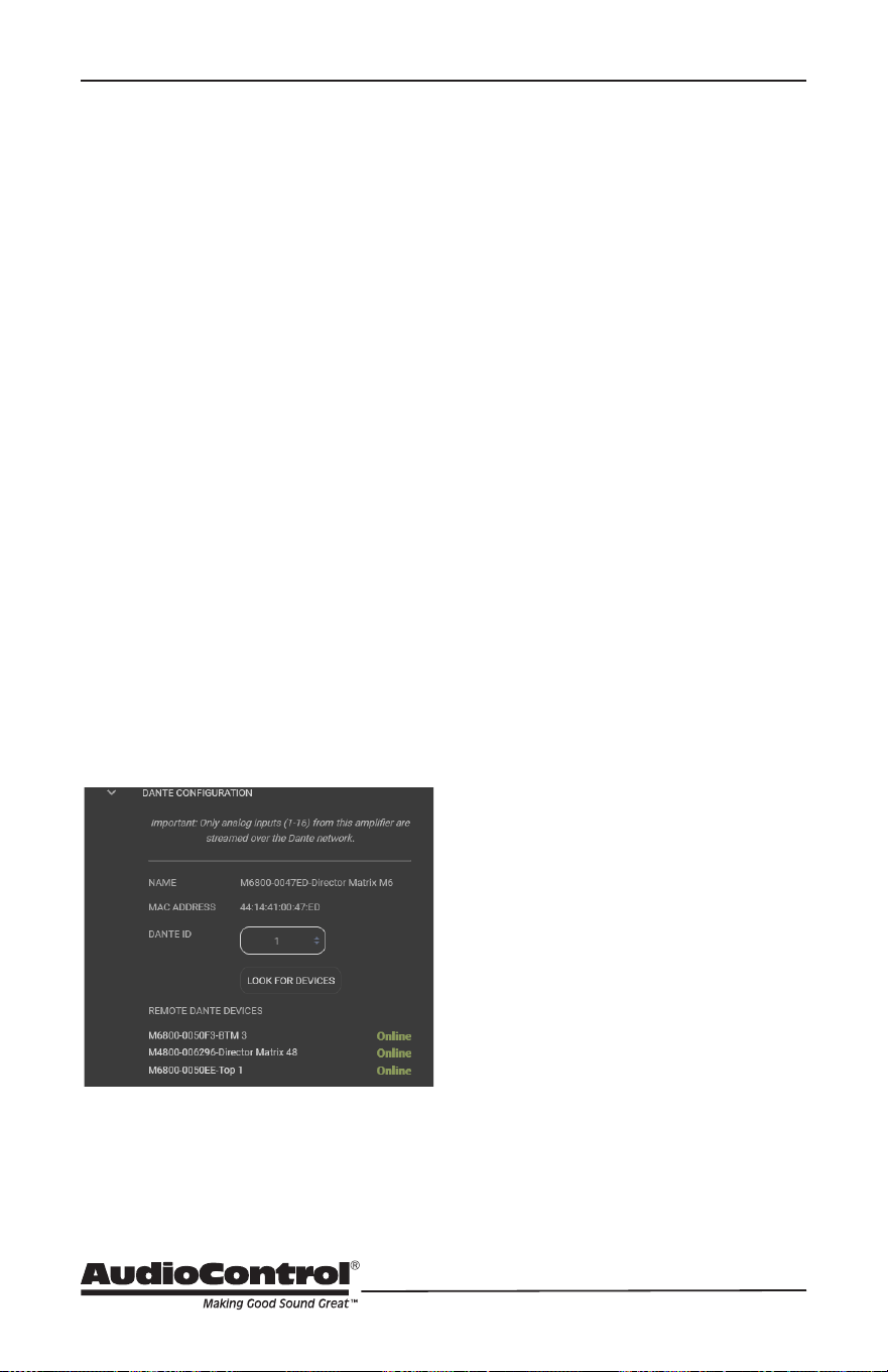
Dante Conguration:
In this menu, other AudioControl Dante-
enabled products may be scanned for.
It is also where the device ID is set,
enabling communication and data
exchange in an automated environment
where other Dante-capable DM6800D
or CM series units are in operation. To
begin, open the “Dante Conguration”
option in the Global Settings dropdown,
and set the ID for this DM6800D. If on a
network with additional Dante devices,
select “Look for other devices.” This
process will populate the input selection
menus of remote AudioControl CM and
Director series ampliers into this local
device menu, making those remote
inputs available for use by this local
amplifier.
Agnostic, third-party-automated
system integration also is done with this
menu. Set the DM6800D as the first
AudioControl Dante-enabled unit you
are logging as Dante ID 1.
The unit will scan for other Dante
devices to make sure position #1 has
not been taken previously. If an all-clear
is given, this device and its MAC
address will be known on the system as
device #1.
ID all other Dante AudioControl devices
in the system so they can communicate
with each other and enable remote
control of Dante routing by automation
systems like Control 4, Creston, and
others.
Using Dante Controller, physical
M6800D inputs become virtual sources
that are available to other Dante
devices with input/amplification
capabilities. Non-AudioControl Dante
sources can also be routed statically to
the Director's 8 stereo virtual inputs
which are then accessible from the
input selection menu and/or the
automation system. Inputs may also be
renamed and published to the Dante
bus which will inform the Dante
Controller.
AudioControl Dante amplifiers can
matrix signals between other
AudioControl Dante amplifiers. For
systems with more than 8 non-
AudioControl Dante sources, a third-
party controller may be required to
dynamically route Dante streams not
created by the AudioControl amps.
Check out AudioControl's knowledge
base at support.audiocontrolpro.com
for more in-depth information about
setting up and integrating our Dante-
enabled amplifiers into your system.
Dante Conguration

41
Installation Manual
Model M6800D
THE DIRECTOR
™
Since sound is energy, the way it reects
depends upon the angle of the surface,
the type of surface material and the
frequency of the sound wave. A listening
position is likely to be nearer the back
of the Free Field (waves shown in the
diagram) enveloped by part of the
reected Reverberant Field as well.
Added in are the next set of complications:
Dierent frequencies of sound have
dierent wavelengths (a function of
frequency and the speed of sound). Each
frequency’s wavelength contributes
dierently to the Free and Reverberant
Fields because they are dierent sizes.
For example, a 32 Hz bass note has a
wavelength of 35 feet, while a 16,000
Hz note has a wavelength of just under
a tenth of an inch. Tiny treble waves can
be caught and neutralized by draperies,
carpeting, and upholstered furniture while
gigantic bass waves simply slosh back and
forth within the room.
Another set of variables is the shape and
size volume of a listening room. Large
rooms require more bass energy to excite
waves within them. Small rooms need less
energy but reect it dierently. And then
there’s the fact that most rooms don’t
have four walls anymore, opening into
dining rooms, lofts, cathedral ceilings, etc.
All of this means that predicting sound
interaction patterns is very dicult due
to irregularities in room shapes.As you
can see, room acoustics is an important
but complicated subject. The overall point
being emphasized is various rooms in a
home function as a gigantic mechanical
equalizers, boosting or cutting certain
frequencies depending on size, shape,
volume, acoustic treatment and the
position of the speakers.
Acoustics
Acoustics
Media venues that evaluate audio
products, including speakers, only do
so in what they deem a “reference
environment.” Such acoustic settings
are incapable of being identically
duplicated by consumers of this media,
but they impart more impact to the nal
performance assessment of the product
being considered, especially loudspeakers,
than any other factor. Acoustics is a
complicated subject, like a Nancy Myers
lm, about which hefty textbooks have
been written. We simply want you to be
aware of a few basics that have a direct
eect on real-time audio analysis. Sound
travels in waves. In audio systems, these
waves are created by the speakers. Like
waves in a pond created by a splash,
sound waves emanate from speakers to
spread out into the room. If a room were
innitely large, that’s all there would be
to it. But just as waves in a pond reach
the bank and reect back, sound waves
bounce o walls, ceilings, and oors,
reecting, reinforcing and canceling one
another as shown here:

42
Equalizing the System
Before proceeding with equalizing the
system, it is a good idea to make sure
everything is connected and working
properly.
These are reminders specic to The
Director M6800D, as well as the steps for
equalization.
1. Turn on the system. The Power light
on the left front panel should be blue.
2. Connect to this specic Director
unit over the network by entering
its unique IP address into a browser
(Firefox, Safari, and Chrome are
preferred).
3. Make sure the unit is turned on. Turn
o signal sense in the Web Interface
on the browser. On the front panel,
all zone status lights should start red
and then turn to blue.
4. If any zone status lights are not blue,
check the Web Interface to see if any
zones need to be unmuted.
5. Play (Barbie) pink noise through the
system into the zones to be adjusted.
The signal is playing through the
M6800D when the LED level meter
on the front panel responds to the
volume.
6. Assuming you have wireless network
access and an RTA meter for sound
analyzation, go into the zone you
wish to adjust.
7. Place the microphone in the middle
of the listening area at the height of a
typical listener’s head.
8. Use the equalizer controls to lower
peaks in the frequency response
rst. Peaks obscure the surrounding
sounds. Lowering peaks will unleash
overshadowed sounds.You can
save dierent settings to dierent
memories and see which one the
clients like. Their taste may be
dierent than yours.
Equalization
Benets of Equalization
Rarely is the room and room décor
designed to get the best sound from an
audio system. Almost always the opposite
is the case, where speaker positions and
sizes become dictated by factors that are
contrary to accurate sound. This real-
world situation is where equalization
provides tremendous benets. Speaker
positions, furniture, and room layouts
may cause peaks in frequency response.
Fortunately, these peaks can be tamed
by careful equalization. Clients may
have specic preferences, and sound
may be tailored to accommodate these
preferences. Remember, there are
memories in The Director M6800D, and
dierent settings via these memories may
be used for dierent sources.
The laws of physics are dicult to violate,
although we do try our best. Equalization
cannot make terrible acoustics sound
terric, only better. For example, if a room
has a tile oor and glass walls, the best
result will still be bad by any barometer.
While equalization can do wonders to
aid a less than perfect speaker, it will
never make a mediocre speaker sound
fabulous. For the best results, start with
well-designed, accurate speakers and
reasonable room acoustics whenever
possible.

43
Installation Manual
Model M6800D
THE DIRECTOR
™
Parametric and Graphic
Equalization
The graphic equalization controls in the
M6800D are selected to correspond
with the characteristics of in-wall and
in-ceiling speakers, and as such are
very eective. Graphic EQ controls
are the easiest to tune, and provide a
“graphic” representation of what the
adjustments are. Parametric equalization
requires selecting the frequency, the
bandwidth of the control, as well as the
level of adjustment, not an easy task
to get correct. In general, parametric
equalization is valuable for very large
areas of change or very narrow areas.
Parametric equalization in the M6800D is
best used for taming very narrow peaks.
Do not use it for very narrow dips, as these
dips are likely caused by cancellations and
will not respond to boosts in equalization.
Here is an introduction to each of the
graphic control frequencies and their
eect on music.
45 Hz — Low bass
• This is about the lowest frequency
that in-wall and small bookshelf
speakers can achieve. Boosting it
too far might cause problems, even
though the subsonic lter in the
M6800D cuts frequencies below
this adjustment point. But, if your
speakers can take it, a mild boost
will enhance bass instruments such
as bass guitar, kick drum, oor toms,
timpani and double bass violas.
150 Hz — High bass
• There is a lot of bass information at
this frequency. In fact, most modern
music is mixed to enhance this area
of the frequency spectrum. 150Hz
also determines the depth of male
vocals and contains reverberant
information which contributes to
the spaciousness of sound. Boosting
150Hz can add slam and impact
to bass or it can make the sound
hollow and boomy. This is a critical
adjustment with small or in-wall
speakers. Experiment with this range.
300 Hz and 700 Hz
• High and low midrange. These
controls directly aect the sound
of instruments and vocals. These
bands also determine the speaker’s
presence (whether the music
sounds far away or close in). Small
speakers often produce too much
midrange, so these controls can be
turned down slightly during your
initial experimentation. Consider
reducing 700Hz when architectural
speakers are only used for low-level
background music.
Parametric and Graphic EQ

44
2500 Hz — Treble
• Female vocals and the transients
of instruments such as guitars,
snare drums, saxes, violins, etc. are
found in this range. If accentuated
too much (by boosting this control)
sound in the 2500Hz range can seem
harsh and fatiguing to the ear due
to excessive output by the speaker
or because of live, reective room
acoustics.
12 kHz — High treble
• The ne detail, texture and shimmer
of music are found here, such as the
breathiness of vocals, the “sheen”
of cymbals, and the high overtones
of piano and strings. Actually,
there’s audible music information
up to 20,000Hz on some CDs and
hi-resolution streaming services,
with many adult’s hearing very well
at 15,000Hz. 12,000Hz was chosen
because it provides more useful
control to compensate for room
acoustics and common small-speaker
deciencies.
Subsonic and Tweeter Protection
Subsonic and Tweeter
Protection Filters
The Subsonic (aka High Pass) lter and
Tweeter Protection (aka Low Pass)
lter are adjusted on the M6800D
signal processing web page, along with
equalization. Their function is simply to
make speakers sound better, play louder,
and last longer.
All speakers have frequency response
limitations. For their best performance,
speakers should operate in their linear
zone. This is the range where sound
reproduction is not compromised by
mechanical limitations.
If speakers operate near or at their
mechanical limitations, the sound they
reproduce is compromised and elements
of the speakers are stressed and, in
some cases, will heat up shortening
their longevity. The tweeter protection
and subsonic lters are very important
tools. Experiment with higher subsonic
lters, and lower tweeter protection
settings than are suggested from
published specications for the speaker.
Experiments with higher/ lower settings,
will very likely, sound much better than
pushing frequency limits. Speakers will be
less stressed and last longer.
Presets
There are six memory presets on the The
Director M6800D for a variety of dierent
setting congurations. These memories
are saved on the Signal Processing
tab. When saving a memory, all signal
processing page settings (equalization and
lters) are saved.

45
Installation Manual
Model M6800D
THE DIRECTOR
™
Advanced Discussions
In Wall Volume Controls
While in-wall volume controls are
used less now, replaced by automation
systems with wireless control for volume
performed by system controllers, they
may exist in some installations.
The M6800D is capable of producing more
power through a volume control’s circuitry
than it can safely handle. Only use a
volume control that is rated for the power
of the M6800D into a 4 Ohm load, which is
200 Watts per channel, and with a margin
of safety headroom. In all likelihood,
such a control does not exist, as this is an
extreme amount of power.
Installation of
multiple units
How many The Director M6400, M6800,
and M6800D units may be stacked
without ventilation space between
units?
• A maximum of 4 units may be
stacked, one atop another, provided
one unitfree rack space is above
and below the stack. Consider how
the units will be congured and
the impedance loads they may be
operating under. In an installation
where high to maximum output
power may be the norm and not
the exception, increased ventilation
and alternative cooling methods are
recommended.
• Ideally, 2 units stacked with unit-free
space above and below will improve
air ow to the units.
May you daisy chain or Y-cord audio and
power trigger connections?
• Y-cords are not necessary nor
recommended, as the Loop-output
jacks are designed to pass signal to
the next amplier. Use high-quality
cables for signal extension.
• For power control, it is easiest to have
an Ethernet connection to each unit.
The 12 volt mini jacks are powered
to turn on another unit when the
main unit is on (not standby). If you
need more than 15 milliamps current
on the 12 volt output, use a relay to
prevent over loading The Director.
(The Director itself only takes 1
milliamp to turn on.)
What are the power requirements and
BTU outputs of The Director?
• More detailed information is shown
in the specications section. In
general, we feel conservative, real-
life design criteria is 1/8th power. This
will be a quite loud listening level for
most rooms and assumes all zones
are driven at the same time. You will
be amazed at how cool the M6800D
is at this level. One rule does not t
all situations, so knowledge of the
particular circumstances involved
needs to be applied. Also, see the
section below on unique rooms and
SPL.
How many units may be put on one 15-
amp breaker?
• It depends. Since most codes limit
each device to 1500 watts, there
should be a separate 15-amp circuit
for each unit.
Advanced Discussions

46
• The circumstances where the
M6800D draws maximum power are
very rare outside of an engineering
lab. Maximum power is using a sine
wave input which has at least a third
higher energy density than music.
This would mean all channels are
operating at maximum, which is an
unlikely situation, even if you are
trying to resurrect Frankenstein, and
even more unlikely is all channels
on multiple units operating at full
output.
• If the only use is background music,
then the one-eighth power in
the specications is a reasonable
(actually conservative) power draw.
A margin of safety for unusual
circumstances should be included.
Always follow all National and local
electrical codes.
What should I use the “Trim” controls in
the browser for?
The Trim controls are an easy-to-access
level setting control which you can use
while in the zone. The Trim controls allow
minor, not major adjustments.
Unique Rooms and SPL in Large Areas:
Are there any special considerations for
bathrooms?
• Bathrooms are irregular rooms with
high ambient background noise. This
noise is often a noisemasking type of
ambient sound, in a highly reective
acoustic space, and sometimes fairly
large. Modern bathrooms are often
some of the most challenging audio
environments.
• Commercial noise masking systems
rely on “white noise”, which sounds
remarkably like a bathroom exhaust
fan plus the sound of water in a
shower, both of which are louder
than the background noise level
in other parts of a house. Today’s
bathrooms typically demand multiple
pairs of speakers for these reasons.
What about large rooms as well as
rooms where the listener is far from the
speakers?
• Typical in-wall speakers are designed
to be near the listener. In common
rooms with eight foot ceilings and
other usual dimensions, in-wall
speakers typically are not much more
than eight feet from the listener. In
large mansions, the game changes.
Twenty-foot ceilings are normal and
typical speakers are too far away to
provide the client much SPL (sound
pressure level). There are in-wall
speakers designed for these longer
“throw” distances. In general, larger
rooms with more height require more
speakers and speakers with tighter
“directivity” to get party-level SPL.
In this case, size matters, and larger
speakers will perform better.
What about haunted locations and
rooms?
• Who you gunna call?
» Ghostbusters.
Advanced Discussions

47
Installation Manual
Model M6800D
THE DIRECTOR
™
Troubleshooting
Many problems can be eliminated by
re-checking the wiring and settings
of the unit. If a problem cannot
be solved using the guide below,
please call the AudioControl team
for further assistance, or e-mail us at
1. No Sound
a. Verify the Power LED is Blue.
b. Verify Protection LED is O.
c. Verify Zone Status LED is Blue.
d. Verify that the correct input has
been selected in the Web Interface
menus
e. Verify the source unit is operating.
f. Check the speaker connector plugs
on the rear panel are secure.
g. Unplug the power cord and check
the AC Power Fuse on the rear
panel.
2. Protection LED is o, but none
of the Zone Status LEDs are on:
a. Defeat the signal-sense circuits
using the signal sense switch on the
Web Interface Web Interface. All of
the zone status LEDs should turn on.
If they do not, call AudioControl’s
customer service.
b. Verify the source unit is operating.
c. Increase the preamp volume if
signal sense is engaged, or just
going steady.
3. Channel Status LED is Red:
a. Check speaker leads for a short.
Swap speaker connectors on rear
to see if the problem moves with
the wires.
b. If the unit is excessively hot, turn
down the volume and allow it to
cool o. The protection LED should
turn o after a short while. Verify
that any ventilation holes have not
become blocked.
c. The speaker impedance may
be too low. Use an ohmeter to
measure the impedance on the
speaker wires.
4. Speaker channels are cutting in and
out:
a. If using external volume controls,
check that they can handle the
power output.
b. Make sure the speaker impedance
is not less than 4 Ohms, or 8 Ohms
when used in bridged mono.
c. There may be a short in the wires.
Suspect a short if the problem
happens only at the highest
volumes.
5. Protection LED is Red:
a. Disconnect power from the unit
for 3 to 4 minutes and reconnect to
power.
b. Disconnect all speaker wires. If
it still turns red, and the unit has
cooled, something rather serious
has happened inside the unit.
Call AudioControl’s lonely folks in
customer service.
c. We are going to need a bigger
boat.
Troubleshooting
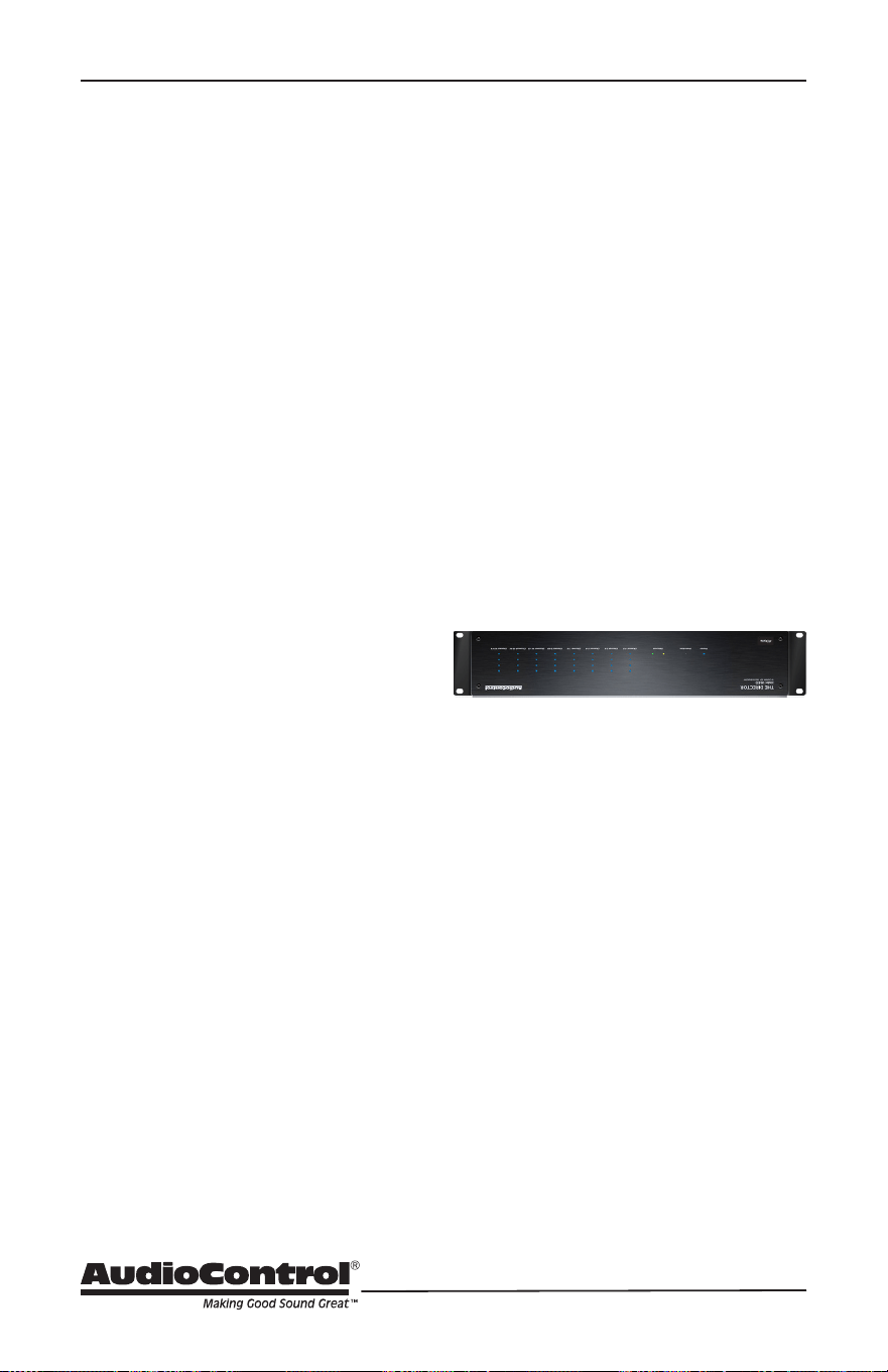
48
Troubleshooting
6. Speaker Buzzing or Crackling at
high volume:
a. Reduce any preamplier/equalizer
low-frequency boost.
b. Ripley: “there’s an alien on this
ship, get out of here”
7. There is no audio input signal, but
the Zone Status LEDs are still blue:
a. Check the signal-sense switches
in the unit’s Web Interface tabs.
If they are not engaged, the zone
status LEDs will stay on as long as
the master trigger is enabled.
b. The zone status LEDs stays on for
2 minutes (depending on music
volume) after the audio signal has
stopped. This delay helps prevent
prematurely muting during quiet
passages or song changes.
8. The unit is on but you cannot
trigger it o
a. The unit will stay on if either
the 12v master trigger is on, or
jumpered on.
b. If the unit has come unplugged and
is still powered on after 4 hours,
please consult your physician.
9. Is an in-wall volume control rated at
80 Watts (continuous) adequate?
a. Just barely is the simple answer.
Go for one with a higher rating if
you want a reliable long-lasting
system. Though the Director
M6800D is rated at 100 Watts, it
is a conservative number, and it
can put out more power if only
a few channels are driven. In
contrast to the conservative rating
of the Director M6800D, the wall
volume control may be rated using
favorable assumptions. Also make
sure the volume control power
rating is continuous not peak. The
continuous rating is about one-
third of peak.
10. The Director M6800D looks like
this:
a. It has been installed upside down.
b. You are trying a new Yoga position.
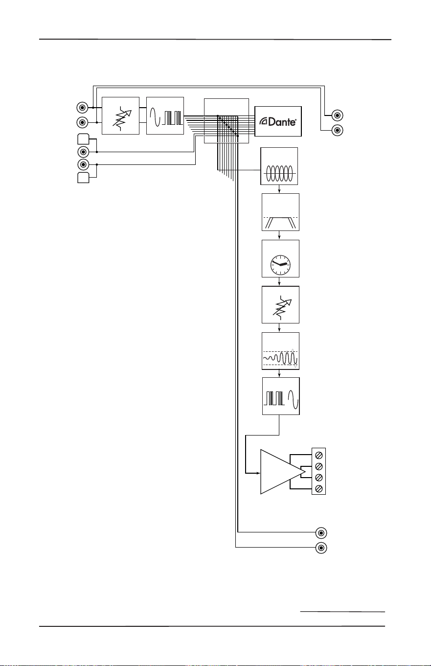
49
Installation Manual
Model M6800D
THE DIRECTOR
™
Block Diagram
Block Diagrams
Time Align
Delay
Analog
Pass Thrus
1 - 16
Analog
Inputs
1 - 16
DAC
ADC
Parametric
Graphic EQ
High Pass /
Low Pass
Filters
Volume
Gain
Digital
Inputs
A - B
Limiter
Amplifiers
Speaker
Outputs
1 - 16
S/PDIF
Outputs
A - B
Stereo Matrix
10 X 10
Dante Outputs 1-16
*Flux Capacitor not labeled

50
Specications
M6800D Specications
Output Power
Per Channel ............................................ 100 Watts @ 8 Ohm, 200 Watts @ 4 Ohm
Bridged Mono .......................................................................... 400 Watts @ 8 Ohm
Signal to Noise Ratio ............................................................. > 95 (A wtd, ref full output)
Crosstalk ............................................................................................... > 80 dB @ 1 kHz
Damping Factor ......................................................................................................> 300
Gain ....................................................................................................................... 30 dB
Analog Input Sensitivity ....................................1 Vrms for full output, level at maximum
DAC Specications ............................................32 – 96 kHz sample rate, 16/24 bit depth
AC Power Requirements
Standby .................................................................................................... <2 Watts
Idle ............................................................................................................ 53 Watts
1/8th power (loud listening level) ..............................................................330 Watts
Full Power (20 A residential service limited) ........................................... 2400 Watts
BTU/hr Output
Standby ..................................................................................................6.8 BTU/hr
Idle ........................................................................................................ 180 BTU/hr
1/8 power (loud listening level) ..............................................................460 BTU/hr
Full Power ............................................................................................ 2124 BTU/hr
Dimensions
Height ....................................................................................................... 3.5” (2U)
Width (ears on) ................................................................................................19.0”
Width (ears o) ................................................................................................ 17.0”
Depth .............................................................................................................. 15.5”
Weight ............................................................................................................ 21 lbs
Network Settings
Default IP Address ...........................................................................192.168.0.249
Please note: Because of AudioControl’s bold and daring quest to push back the frontiers of
audio perfection, all specications are subject to change without notice, and at any time,
including (and not limited to) lunchtime, teatime, or when our engineers run around the
factory shouting “Eureka!”

51
Installation Manual
Model M6800D
THE DIRECTOR
™
Service
What to do if you need service
If the unit needs service, then please
contact AudioControl, either by e-mail or
phone. We will verify if there is anything
wrong in the system that you can correct
yourself, or if it needs to be sent back to
our factory.
Please include the following items when
returning the unit:
1. A copy of your proof of purchase. No
originals please. We cannot guarantee
returning them to you.
2. A brief explanation of the trouble you
are having with the unit. (You’d be
surprised how many people forget
this.) If you can supply a really detailed
description of the problem, this would
be so much better, and our service
technicians may add you to their
Christmas Card list. Please include
any notes about the system and other
components you are using. Is it an
intermittent problem that only occurs
on the rst full moon of Spring?
3. A return street address. (No PO Boxes,
please).
4. A daytime phone number in case our
technicians have a question about the
problem you are having, or if they are
just feeling lonely.
5. Package the unit in the original
packaging if you still have it. Use
great care and plenty of good packing
materials to protect the unit and
prevent it from moving about inside
the box. Do not use loose materials
like packing peanuts or real peanuts.
You are responsible for the freight charges
to us, but we’ll pay the return freight back
as long as the unit is under warranty. We
match whatever shipping method you
use to send it to us, so if you return the
unit overnight freight, we send it back
overnight. We recommend United Parcel
Service (UPS) for most shipments.
Please do not return the unit to
AudioControl if you have not received
an RMA number from our masterful
customer support team.
Phone 425-775-8461
support.audiocontrolpro.com
www.audiocontrolpro.com/contact-us

52
The Warranty
In just the same way as being covered in
honey and thrown into a dark pit full of
hungry woodchucks, people are scared
of warranties. Lots of ne print. Months
of waiting around. Well, fear no more.
This warranty is designed to make you
rave about AudioControl. It’s a warranty
that looks out for you and your client,
plus helps you resist the temptation to
have your friend Sparky, who’s “good
with electronics,” try to repair your
AudioControl product. So go ahead, grab
a cup of tea, and carefully read through
this warranty.
Our warranty has conditional conditions!
“Conditional” doesn’t mean anything
ominous. The Federal Trade Commission
tells all manufacturers to use the term
to indicate that certain conditions
have to be met before they’ll honor
the warranty. If you meet all of these
conditions, AudioControl will, at its
discretion, perform warranty service on
any AudioControl products that exhibit
defects in materials and/or workmanship
during the warranty on your product for
ve (5) years from the date you bought it,
and we will x or replace it, at our option,
during that time.
Here are the conditional conditions:
1. You need to hold on to your sales
receipt! All warranty service requires
original sales receipt documentation.
The warranty only applies to the
original purchaser from an authorized
AudioControl dealer. Note: Products
purchased from unauthorized dealers
are not covered under warranty.
2. If an authorized AudioControl dealer
installs your AudioControl product,
the warranty is ve years, otherwise
the warranty is limited to one year.
3. Our warranty covers AudioControl
products that have been installed
according to the instructions in the
installation manual.
4. You cannot let anybody who isn’t:
(A) the AudioControl factory; or (B)
somebody authorized in writing
by AudioControl service your
AudioControl product. If anyone other
than (A), or (B) messes with your
AudioControl product, the warranty is
void.
5. The warranty is void if the serial
number is altered, defaced or
removed, or if your product has been
used improperly. Now that may
sound like a big loophole, but here is
what we mean by this: Unwarranted
abuse is: (A) physical damage (don’t
use your product to level your dining
room table); (B) improper connections
(120 volts into the RCA jacks can fry
the poor thing); (C) sadistic things!
This is the best product we know how
to build, but for example if you mount
it to the front bumper of your car,
drop it over the Niagara Falls or use
it for Clay Pigeon shooting practice,
something will go wrong.
Assuming you conform to 1 through 5,
and it really isn’t all that hard to do, we
will have you send your product to us for
warranty service.
Warranty

53
Installation Manual
Model M6800D
THE DIRECTOR
™
Legalese Section
This is the only warranty issued by AudioControl. This warranty gives you specic legal
rights, and you may also have rights that vary from state to state. Promises of how
well your AudioControl product will work are not implied by this warranty. Other than
what we’ve said we’ll do in this warranty, we have no obligation, express or implied. We
make no warranty of merchantability or tness for any particular purpose. Also neither
we nor anyone else who has been involved in the development or manufacture of the
unit will have any liability of any incidental, consequential, special or punitive damages,
including but not limited to any lost prots or damage to other parts of your system
by hooking up to the unit (whether the claim is one for breach of warranty, negligence
of other tort, or any other kind of claim). Some states do not allow limitations of
consequential damages.
Legalease Section
54
Installation Notes
Installation:
Installer:
Zone Room Source
1/2
3/4
5/6
7/8
9/10
11/12
13/14
15/16
Notes/Poems/Sagas/Odes
Installation Notes

55
Installation Manual
Model M6800D
THE DIRECTOR
™
Installation Notes
Notes/Poems/Sagas/Odes
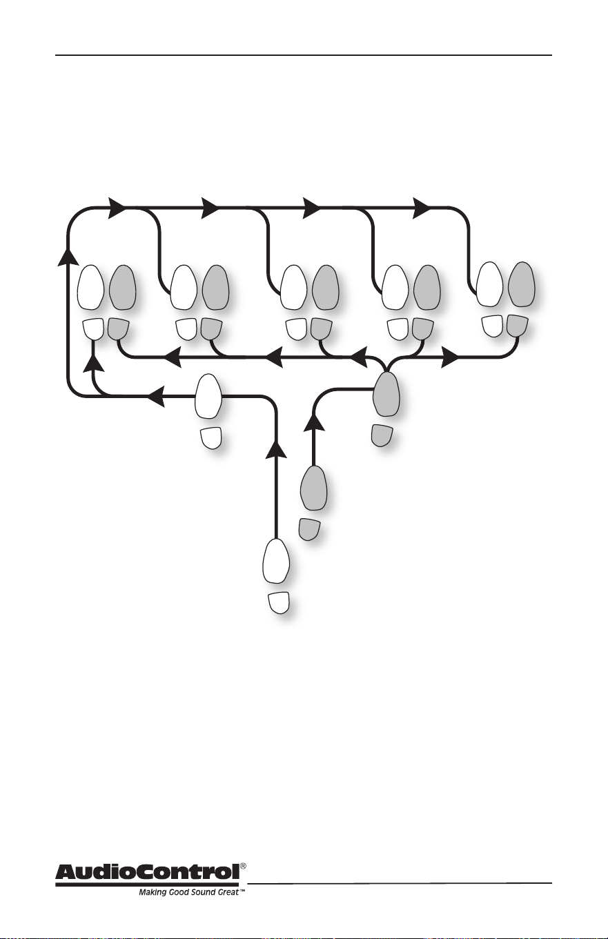
56
Hurrah, You are done!
The Dante Boogie
2
1
5 6
3
START
FINISH
4
5 65 6
5 6
5 6
FINISHFINISHFINISHFINISH
Other common names for this dance:
• Dante Boogie Nights
• Dante 2 Electric Boogaloo
• Dante Inferno
Manual PN 913-190-0 Rev B