1. SAFETY
WARNING! Ensure that Health and Safety, local authority and general workshop practice regulations are adhered to when using tools.
WARNING! Air brushes produce a ne mist of paint and solvents which may be harmful by inhalation.
9 Always wear suitable protective breathing equipment which can be obtained from your local Sealey Dealer.
9 For a better understanding of the risks involved with any particular paint or solvent read the warnings on the containers and follow
the advice given. Also take measures to protect the eyes and skin from contact with paint and solvents. A full range of personal safety
equipment is available from your Sealey stockist.
8 DO NOT operate the air brush near other people unless they are wearing the same protective equipment.
8 DO NOT eat or drink when using the air brush.
8 DO NOT allow smoking or open ame in the work area.
9 Ensure that the air brush and accessories are in a clean, sound condition and good working order. Take action for immediate repair or
replacement of damaged parts. Use recommended parts only. The use of unauthorised parts may be dangerous and will invalidate the
warranty.
9 Ensure the air brush supply hose is not tangled, twisted or pinched.
8 DO NOT use air brush or accessories if damaged.
8 DO NOT operate air brush while under the inuence of drugs, alcohol or intoxicating medication, or if fatigued.
8 DO NOT direct spray against yourself, other persons or animals or electrical equipment.
8 DO NOT use the air brush for a task it is not designed to perform.
9 Always ensure adequate ventilation in the work area.
9 Always disconnect from the air supply before dismantling the air brush for cleaning and maintenance.
8 DO NOT leave the air brush connected to the air supply when unattended.
2. INTRODUCTION
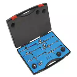
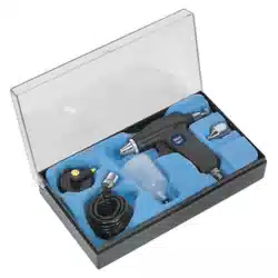
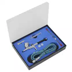
Metal body construction with built-in gravity feed pot. Double-action trigger providing precision control of paint ow. Supplied tted with
0.3mm nozzle. Includes alternative 0.2 and 0.5mm set-ups, 1.8m small-bore hose, adjustment spanner and pipette. Supplied in storage
case.
3. ASSEMBLY
3.1. Screw one end of the air hose onto the air hose connection underneath the air brush trigger and the other end onto the air supply.
3.2. To use a compressor such as the Sealey Model No: AB900 use the adaptor supplied with the compressor to connect the air hose.
3.3. To use the air brush with other types of compressors use the 1/4” reduction nipple supplied.
NOTE: The maximum air supply to the air brush should never exceed 50psi. Normal operating pressure is approx 30psi.
4. SPECIFICATION
Model No: ..........................................................AB9321
Cup Capacity: ........................................................... 7cc
Nozzle Size(s): ....................................... 0.2, 0.3, 0.5mm
Working Pressure: ............................................. 15-50psi
5. OPERATION
Thank you for purchasing a Sealey product. Manufactured to a high standard, this product will, if used according to these instructions,
and properly maintained, give you years of trouble free performance.
IMPORTANT: PLEASE READ THESE INSTRUCTIONS CAREFULLY. NOTE THE SAFE OPERATIONAL REQUIREMENTS, WARNINGS & CAUTIONS. USE
THE PRODUCT CORRECTLY AND WITH CARE FOR THE PURPOSE FOR WHICH IT IS INTENDED. FAILURE TO DO SO MAY CAUSE DAMAGE AND/OR
PERSONAL INJURY AND WILL INVALIDATE THE WARRANTY. KEEP THESE INSTRUCTIONS SAFE FOR FUTURE USE.
GRAVITY FEED AIR BRUSH KIT
MODEL NO: AB9321
Refer to
instruction
manual
Wear a mask Wear protective
gloves
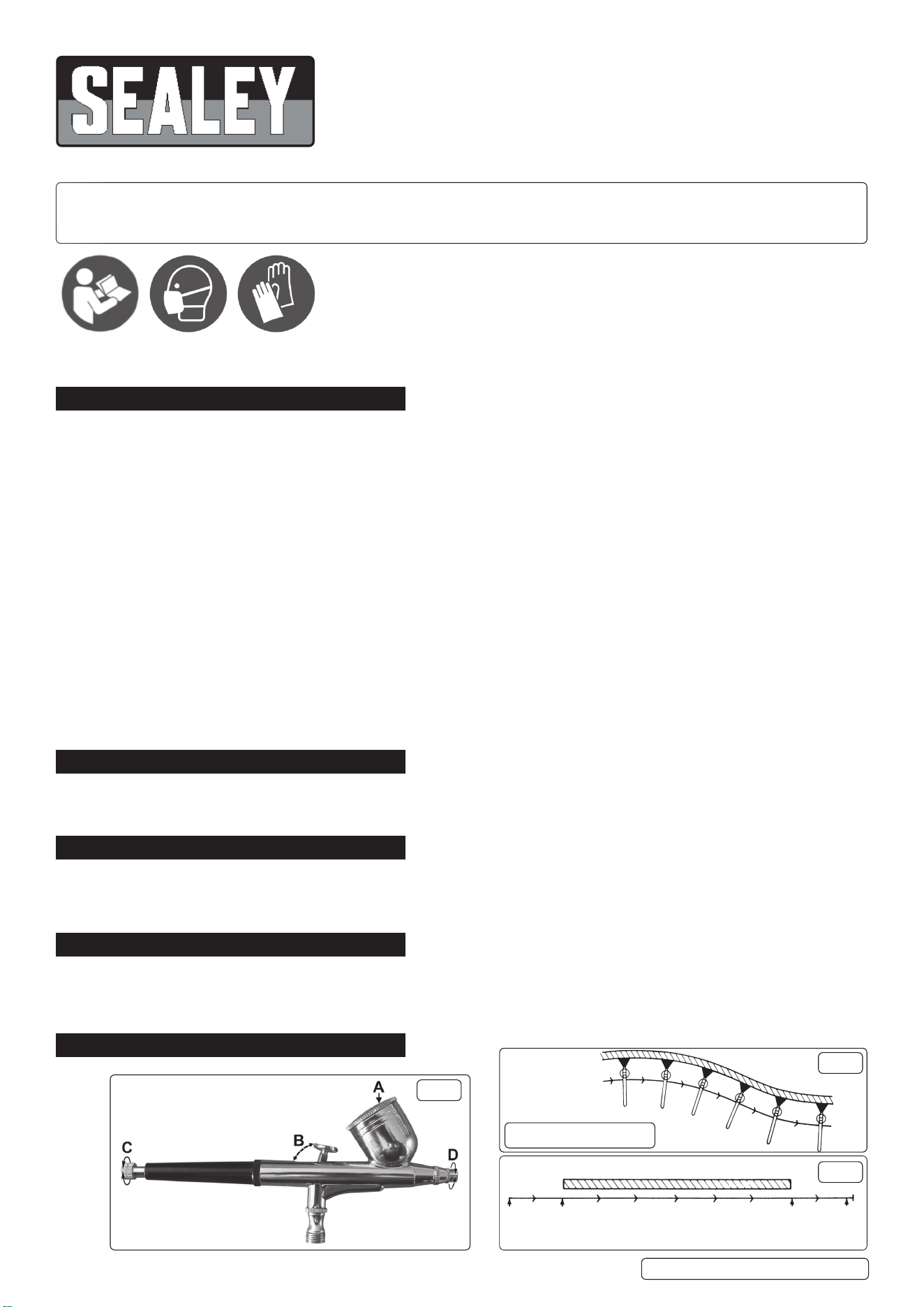
Fig.1
KEEP AIR BRUSH
PARALLEL TO SURFACE
Fig.2
SURFACE
START
MOTION
HERE
PRESS
TRIGGER
HERE
RELEASE
TRIGGER
HERE
FOLLOW
THROUGH
MOTION
KEEP MOTION
STEADY AND SPRAY
Fig.3
AB9321 Issue 3 (ALL) 06/07/23Original Language Version
© Jack Sealey Limited

WARNING! Ensure adequate ventilation.
8 DO NOT spray near naked ames.
5.1. Mask the area which is NOT to be painted.
5.2. Ensure the object to be painted is free from dust, grease and the surface has been prepared.
5.3. After mixing and thinning the paint, as instructed by the paint manufacturer, ll the gravity feed pot just over half full.
NOTE: Mix thoroughly, making sure that the paint is free from lumps. It may be necessary to strain the paint rst.
5.4. Turn the air ON and test your spray on a test panel to get the “feel” of your air brush.
5.5. Make any necessary spray adjustments. The paint spray pattern can be adjusted by turning the xing nut (Fig.1D). The nut is fully
closed, when it has been turned clockwise to the stop point. The volume of paint dispensed can be adjusted by varying the backward
movement of the trigger (Fig.1B). This can be pre-set using the micro adjust screw (Fig.1C).
5.6. Holding the air brush about 15cm inches from the surface press the trigger (Fig.1A) down. Using short strokes, move the air brush at a
steady rate, parallel to the surface, see Fig.2.
5.7. Apply a light coat of paint, let it dry, then apply another coat. Continue with this method until the desired coverage is reached
DO NOT spray too heavily.
NOTE: When using quick drying paints, it is advisable to clean or immerse the uid end of the air brush in a compatible solvent
between sprays.
5.8. Once you are satised with the results of your test pieces and have made any necessary adjustments to the air brush, continue with
the task to be performed. Best results are achieved with a good constant motion. Start the motion before pressing the trigger and follow
a through motion after releasing the trigger, see Fig.3.
6. MAINTENANCE
Numbers refer to the attached parts list.
NOTE: To achieve the best results when spraying it is always best to start with the air brush clean and totally free from old paint
deposits, dirt etc. Therefore the air brush should be thoroughly cleaned immediately after each operation.
6.1. Remove the excess paint from the paint pot, wipe the inside thoroughly, including the lid.
6.1.1. Fill the gravity feed pot half full of a compatible solvent.
6.1.2. Spray into a suitable container, this will clean the needle and nozzle assembly. Hold a soft cloth over the xing nut and spray again, this
will force air and the compatible solvent back through the air brush and clean the internal moving parts.
6.2. Should the air brush become clogged with paint, dismantle the air brush and clean the component parts as follows:
NOTE: Numbers in brackets refer to item numbers on the parts diagram.
6.2.1. Turn off the air and disconnect the air hose from the air brush.
WARNING! The uid needle has a long sharp point and great care should be exercised when handling it.
6.2.2. Unscrew the needle cover (16) from the main body of the air brush and slide it off.
6.2.3. Unscrew the needle xing screw (13) and slide it off the needle. Carefully withdraw the uid needle (5) and place it somewhere safe to
avoid bending it or damaging the sharp point.
6.2.4. Unscrew the nozzle caps (1,2) from the front of the air brush.
6.2.5. Loosen the nozzle assembly (3) with the wrench provided and unscrew it. If the nozzle needs to be soaked in solvent remove the ‘O’
ring (4) as it may be damaged by the solvent.
6.2.6. Unscrew the needle guide assembly (12, 13, 14 & 15) from the rear of the air brush body. Test the action of the sprung plunger. If this
operates smoothly no further disassembly is required.
6.2.7. The lever (9) and lever guide (10) will now be loose in the body and should be removed.
6.2.8. Any components with dried paint on them should be cleaned with a solvent suitable for the paint last used and may need to be soaked
for a while before the paint will come off. Take great care not to bend the needle when cleaning it and avoid the sharp point.
6.3. Reassemble the cleaned air brush as follows:
6.3.1. Replace ‘O’ ring (4) onto the nozzle assembly (3) and screw nozzle into place on body (8A).
8 DO NOT overtighten as this may restrict the effectiveness of the spray pattern.
6.3.2. Position the lever (9) into the opening in the top of the air brush so that it sits on top of the air valve.
6.3.3. The slot in the stem of the lever should be orientated to allow the needle to pass through it when the needle is re-inserted.
6.3.4. Insert the lever guide (10) into the rear opening of the air brush body such that the convex face of the upper section rests against the
lever.
6.3.5. Screw the needle guide assembly (12, 13, 14 & 15) into the back of the air brush until it makes contact with the curved lever (10).
Continue to screw it in until the trigger moves forwards.
6.3.6. Carefully insert the needle (5) into the needle guide assembly and push it through until the needle tip just emerges from the nozzle
assembly (3). Do not force it into position but allow the needle to ‘rest’ in place.
6.3.7. Slide the needle adjuster sleeve (17) over the end of the needle and screw it into the rear of the needle guide assembly.
6.3.8. Test the action of the lever to ensure that the needle withdraws smoothly into the nozzle as the lever is pulled back.
6.3.9. Screw the nozzle caps (1,2) onto the nozzle (3). Do not do them up too tightly. Screw the back cover (16) onto the back of the air brush
body.
7. TROUBLESHOOTING
PROBLEM POSSIBLE CAUSE SOLUTION
Paint Runs. Too much paint applied.
Moving air brush too slowly along workpiece.
Press trigger lightly.
Move at a faster speed.
Grainy Spray. Paint too thick.
Dried paint deposits on tip, needle or regulator.
Thin paint.
Clean air brush, as described above.
Paint Splattering. Needle snapping back into tip. Release needle gently.
Curved Stroke. Air brush not being kept parallel to work. Keep air brush parallel to the work, unless curved stroke is desired.
Paint Spitting. Needle snapping back into tip.
Paint too thick.
Release needle gently.
Thin paint.
Restricted Spray. Air adjusting valve screwed in too tight.
Paint tube in pot clogged.
Loosen the air adjusting valve to obtain the correct spray.
Clean as described above.
AB9321 Issue 3 (ALL) 06/07/23Original Language Version
© Jack Sealey Limited

Sealey Group, Kempson Way, Suffolk Business Park, Bury St Edmunds, Suffolk. IP32 7AR
01284 757500 sales@sealey.co.uk www.sealey.co.uk
ENVIRONMENT PROTECTION
Recycle unwanted materials instead of disposing of them as waste. All tools, accessories and packaging should be
sorted, taken to a recycling centre and disposed of in a manner which is compatible with the environment. When
the product becomes completely unserviceable and requires disposal, drain any uids (if applicable) into approved
containers and dispose of the product and uids according to local regulations.
WEEE REGULATIONS
Dispose of this product at the end of its working life in compliance with the EU Directive on Waste Electrical and Electronic
Equipment (WEEE). When the product is no longer required, it must be disposed of in an environmentally protective way. Contact
your local solid waste authority for recycling information.
NOTE: It is our policy to continually improve products and as such we reserve the right to alter data, specications and component parts
without prior notice.
IMPORTANT: No Liability is accepted for incorrect use of this product.
WARRANTY: Guarantee is 12 months from purchase date, proof of which is required for any claim.
REGISTER YOUR
PURCHASE HERE
AB9321 Issue 3 (ALL) 06/07/23Original Language Version
© Jack Sealey Limited