Loading ...
Loading ...
Loading ...
2000 Series Installation and Operation
7
System Operation
Switch on the receiver. Do not switch on the transmitter yet.
Receiver On…
The LCD display will light up. If two or more of the RF LCD segments
light up at this point, there may be RF interference in the area. If this
occurs, change operating channels (select another frequency).
How to Make Operating Channel Changes
Operating channel changes (frequency changes) may be made in two
ways: manually and automatically.
To change channel manually
1. Use the Up/Down arrow buttons to reach the desired channel
number.
2. Hold the Set/Scan button until the channel number stops ashing
to set the receiver to the channel indicated. NOTE: Before the
channel has been set, a touch (momentary press) of the Set/Scan
(rather than a hold) will revert the channel to its previous setting.
To change channel automatically
1. Hold the Set/Scan button. The Automatic Scan/Set Mode will
automatically scan for and set the next open channel. LCD screen
will ash “FS” four times to indicate start of scan. ”E1“ will show
on the receiver display when no further usable frequencies remain
in the 10 channel frequency list.
Transmitter On…
Before turning on the transmitter, use the provided screwdriver to
set the transmitter channel selector switches (Fig. E/I ) to the same
numbers as those displayed on the receiver. Always turn the transmitter
off when changing channels (frequencies).
The transmitters have a two-position, on-off power switch. When the
switch is “On,” the transmitter produces both RF and audio.
The transmitters have a two-position RF power select switch, offering
low/high transmission modes to conserve battery life/maximize power.
Factory setting is high.
There is about a half-second delay after the transmitter is switched to
the “On” position before the receiver’s Tone Lock squelch un-mutes the
receiver.
When the transmitter is switched on and in normal operation, the
receiver’s RF signal level indicators will display as dark segments (signal
strength indicators) from bottom to top at the left side of the LCD
display.
Setting Levels
Correct adjustment of transmitter audio input, receiver audio output,
and mixer/amplier input and output levels is important for optimum
system performance.
ATW-T220a Handheld Transmitter
The 2000 Series handheld transmitter has factory pre-set audio input
levels. Factory setting is full clockwise, maximum gain.
1. While speaking/singing into the microphone at typically loud levels,
check the AF meter levels on the receiver. If all ve AF meter bars
are consistently illuminated and distortion is heard through the
system, it may be necessary to adjust the transmitter audio input
level.
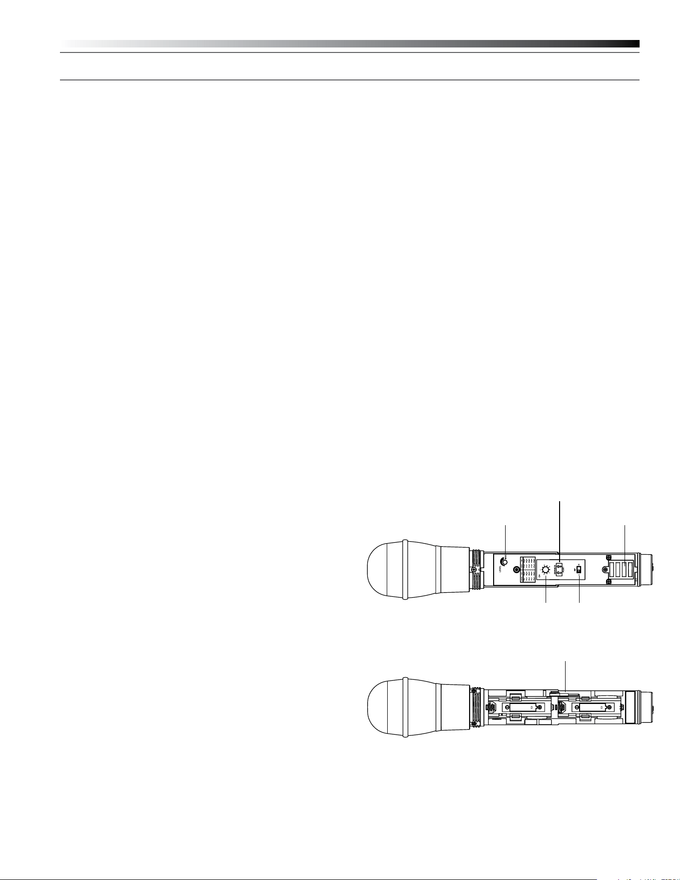
2. To adjust the transmitter audio input level, unscrew the lower body
cover and slide it downwards, exposing the screwdriver and level
trim control (Fig. I). Remove the screwdriver and gently turn the level
trim control counterclockwise until the topmost receiver AF level
meter bar is illuminated only on audio peaks.
3. Return the screwdriver to its clip and close and secure the lower
body. No further transmitter gain adjustments should be needed, as
long as the acoustic input does not change signicantly.
CAUTION! The small trimmer controls are delicate; use only the
supplied screwdriver. Do not force the trimmers beyond their normal
180° range of rotation. Return the screwdriver to its storage clip when
not in use.
Fig. I – Handheld Transmitter Interior View
Charging Contacts
RF Power
Select Switch
Service Port
(for factory use only)
Channel
Selector
Switch
Level Trim Control
Screwdriver
Loading ...
Loading ...
Loading ...