
ELECTRONIC STARTER/CHARGER/MAINTAINER
650/100A 12/24V
MODEL NO: ECS650.V2
Thank you for purchasing a Sealey product. Manufactured to a high standard, this product will, if used according to these
instructions, and properly maintained, give you years of trouble free performance.
IMPORTANT: PLEASE READ THESE INSTRUCTIONS CAREFULLY. NOTE THE SAFE OPERATIONAL REQUIREMENTS, WARNINGS & CAUTIONS. USE
THE PRODUCT CORRECTLY AND WITH CARE FOR THE PURPOSE FOR WHICH IT IS INTENDED. FAILURE TO DO SO MAY CAUSE DAMAGE AND/OR
PERSONAL INJURY AND WILL INVALIDATE THE WARRANTY. KEEP THESE INSTRUCTIONS SAFE FOR FUTURE USE.
1. SAFETY
ELECTRICAL SAFETY
WARNING! It is the user’s responsibility to check the following:
9 Check all electrical equipment and appliances to ensure that they are safe before using. Inspect power supply leads, plugs and all
electrical connections for wear and damage. Sealey recommend that an RCD (Residual Current Device) is used with all electrical
products.
1.1. Electrical safety information. It is important that the following information is read and understood:
9 Ensure that the insulation on all cables and on the appliance is safe before connecting it to the power supply.
9 Regularly inspect power supply cables and plugs for wear or damage and check all connections to ensure that they are secure.
Important: Ensure that the voltage rating on the appliance suits the power supply to be used and that the plug is tted with the
correct fuse.
8 DO NOT pull or carry the appliance by the power cable.
8 DO NOT pull the plug from the socket by the cable.
8 DO NOT use worn or damaged cables, plugs or connectors. Ensure that any faulty item is repaired or is replaced immediately by a
qualied electrician.
If the cable or plug is damaged during use, switch off the electricity supply and remove from use.
Ensure that repairs are carried out by a qualied electrician.
WARNING! Modern vehicles contain extensive electronic systems.
You are required to check with the vehicle Manufacturer, for any specic instructions regarding the use of this type of equipment on
each vehicle. No liability will be accepted for damage / injury, where this product is not used in accordance with all instructions.
▲ DANGER! BE AWARE, LEAD-ACID BATTERIES GENERATE EXPLOSIVE GASES DURING NORMAL BATTERY OPERATION. FOR THIS
REASON, IT IS VERY IMPORTANT TO READ AND FOLLOW THESE INSTRUCTIONS CAREFULLY EACH TIME YOU USE THE CHARGING
EQUIPMENT. Follow these instructions and those published by the battery manufacturer and the maker of any equipment you intend to
use in the vicinity of the battery. Remember to review warning marks on all products and on engines.
1.2. PERSONAL PRECAUTIONS
9 When working with or near a lead-acid battery ensure there is another person within hearing range and close enough to come to your
aid, should a problem arise.
9 Wear safety eye protection and protective clothing. Avoid touching eyes while working near battery.
9 Have fresh water and soap nearby in case battery acid contacts skin, clothing, or eyes.
9 Wash immediately with soap and water if battery acid contacts skin or clothing. If acid enters eye, flush eye immediately with cool,
clean running water for at least 15 minutes and seek immediate medical attention.
9 Remove personal metallic items such as rings, bracelets, necklaces and watches. A lead-acid battery can produce a short-circuit
current high enough to weld a ring or the like to metal, which may cause severe burns.
9 Ensure hands and clothing, including belts, are clear of fan blades and other moving or hot parts of the engine. Remove ties and contain
long hair.
8 DO NOT smoke or allow a spark or flame in the vicinity of the battery or the engine.
1.3. GENERAL SAFETY INSTRUCTIONS
9 Familiarise yourself with the applications, limitations and potential hazards relating to the starter/charger. Also refer to the vehicle
manufacturer’s handbook. IF IN ANY DOUBT CONSULT A QUALIFIED ELECTRICIAN.
9 Ensure the starter/charger is in good order and condition before use. If in any doubt, do not use the unit and contact an electrician.
9 Only use genuine parts. To use unapproved parts may be dangerous and will invalidate your warranty.
Original Language Version
© Jack Sealey Limited
Refer to
instructions
Electrical
shock
hazard
Wear eye
protection
Wear protective
gloves
Warning
corrosive
substance
Warning:
explosive
material
Keep away
from sources of
ignition
Use in well
ventilated areas
Keep in dry area
protect from rain
ECS650.V2 Issue 2 (3) 16/01/24

Original Language Version
© Jack Sealey Limited
9 Use the starter/charger in the vertical position only and ensure it stands on a stable surface which will adequately support the weight.
9 Ensure the charger is switched off and disconnected from the mains power supply before attaching the power clamps to the battery.
9 Keep tools and other items away from the engine and ensure that you can see the battery and working parts of the engine clearly.
9 If the battery has removable caps to access the battery fluid, remove the caps and check the fluid level before connecting the power
leads.
9 If necessary top-up the battery with distilled water by referring to the battery manufacturer’s instructions, (apply the personal safety
precautions described in para. 1.2.).
8 DO NOT dis-assemble the starter/charger for any reason. It must be checked by qualified service personnel only.
9 The cables may become hot with excessive use. If so, allow a few minutes for them to cool down before attempting to re-use.
9 If the starter/charger receives a sharp knock or blow, the unit must be checked by a qualified service agent before using.
9 When not in use, store the starter/charger carefully in a safe, dry, childproof location.
9 Ensure the positive cable is connected to the correct voltage connection on the charger as for the voltage of the battery being charged.
9 Keep children and unauthorised persons away from the work area.
8 DO NOT try to charge a non-rechargeable battery.
8 DO NOT try to start with a frozen battery. DO NOT attempt to charge a frozen battery.
WARNING! DO NOT allow metal tools to touch both battery terminals at the same time. The resulting spark or short circuit may cause an
explosion.
8 DO NOT pull the cables or clamps from the battery terminals.
8 DO NOT use this product to perform a task for which it is not designed.
WARNING! DO NOT simultaneously charge different types of batteries.
WARNING! If a fuse blows, ensure that it is replaced with one of identical type and rating.
9 If the battery terminals are corroded or dirty, clean them before attaching the starter/charger clamps.
8 DO NOT use the starter/charger outdoors, or in damp, or wet locations, and DO NOT operate within the vicinity of flammable liquids or
gases.
8 DO NOT situate charger inside a vehicle or under the vehicle bonnet. Ensure that there is sufficient ventilation and DO NOT cover or
obstruct the starter/charger ventilation louvres.
8 DO NOT allow clamps to touch each other or to make accidental contact with any part of the vehicle.
8 DO NOT cross-connect power leads from starter/charger to the battery. Ensure positive (+ RED) is to positive and negative (- BLACK) is
to negative. If symbols cannot be distinguished, remember that the negative terminal is normally the one directly connected to the
vehicle bodywork.
NOTE: This appliance can be used by children aged from 8 years and above and persons with reduced physical, sensory or mental
capabilities or lack of experience and knowledge if they have been given supervision or instruction concerning use of the appliance
in a safe way and understand the hazards involved. Children shall not play with the appliance. Cleaning and user maintenance shall not
be made by children without supervision.
2. INTRODUCTION
Fully electronic, microprocessor controlled battery starter/charger designed to meet the requirements of modern battery technology.
Suitable for EFB and AGM/GEL (stop/start), Lead Acid, Lead Calcium and Silver Calcium batteries found on electric and hybrid
vehicles. Features up to ten analysis and charge phases, including trickle/maintenance and suitable for 12V and 24V electrical
systems. Instant visual check of battery condition, charge current, voltage and charging rate via LED read-out. Stabilised charging
current allows improved charging efciency and reduced charging times using ECS (Electronic Control Systems) technology. Includes
circuitry to provide surge and spike protection during charging and starting, preventing damage to vital systems such as ABS, airbag
sensors, ignition and music systems. Features power supply mode, providing support for the battery to prevent it from being drained
during prolonged electronic diagnostic checks and software updates.
3. SPECIFICATION
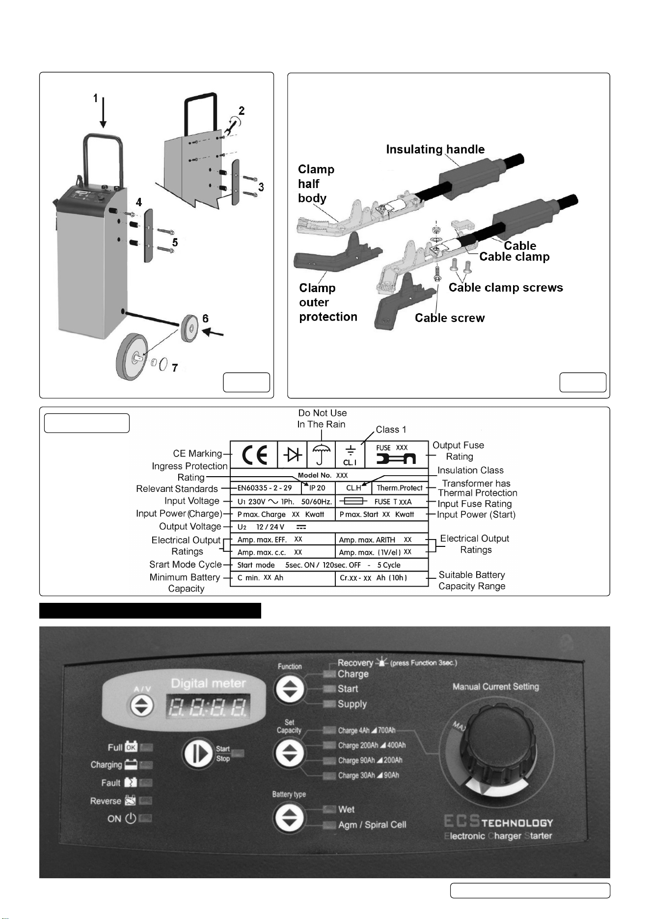
4. ASSEMBLY
4.1. Carefully unpack all components and prepare a surface on which you can lay the unit down on during assembly, without damaging it.
4.2. Insert the handle (g.1.1) and secure it through the rear of the unit with screws (g.1.2).
4.3. Screw on the clamp holders to each side (use the long screws) (g.1.5) and the mains cable holder on the rear (g.1.3).
4.4. Lay the unit on its front in order to insert the axle. Fit the wheels (g.1.6), then their retainers and caps (g.1.7).
4.5. CLAMP ASSEMBLY (g.2). (Supplied assembled)
4.5.1. Push cable through insulating handles.
4.5.2. Locate cable using cable screw washer and nut, note which way up cable needs to be. Screw on cable clamp tightly.
4.5.3. Screw up cable screw tightly.
Model No: .................................................... ECS650.V2
Battery Range: ..................................................4-700Ah
BSU Supply: ................................................ 40A - 13.5V
Cable & Clamp Length: ............................................. 2m
Charging Rates: 3 x Preset +1 x Variable to Max. Current
Fuse: ......120/802131 (Pack of 10), 120/122452 (single)
Input Charge: ................................................2kW - 8.5A
Input Start: ...................................................12kW - 52A
Output Charge Peak (EN): ............................100A(70A)
Output Start Peak (EN): ..............................650A(450A)
Plug Type: ........................................... Blue - 32A-2P+E
Polarity Protection: ................................Fuse (3 x 100A)
Power Supply Cable Length: ..................................1.6m
Supply: ......................................................... 230V - 32A
NOTE: *Performance dependent on connection to an adequate, good clean electric supply.
ECS650.V2 Issue 2 (3) 16/01/24
Original Language Version
© Jack Sealey Limited
4.5.4. Push outer protection pieces onto the ends of the clamp.
4.5.5. Slide insulating handles up to meet the outer protection pieces.
4.5.6. Repeat for all clamps.
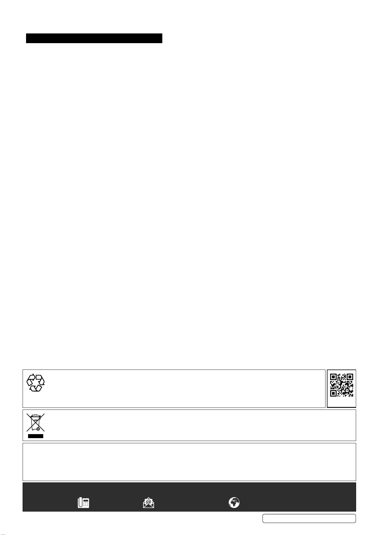
5. CONTROL PANEL
6.
g.1 g.2
Data Plate
ECS650.V2 Issue 2 (3) 16/01/24
For reference.
Supplied assembled.

Original Language Version
© Jack Sealey Limited
6.1. SIGNALLING LEDS
There are 15 LEDs on the front panel having the following functions:
• 4 battery status LEDs, indicating:
Full:...............................battery is charged and is in Charge Maintenance status.
Charging: ..........................battery charging.
Fault:..............................battery is damaged.
Reverse: . . . . . . . . . . . . . . . . . . . . . . . . . . . polarity reversal.
• 1 battery charger status LED:..........ON LED, battery charger ON (colour BLUE).
• 1 operating status LED: ..............indicates whether output is in accordance with selected mode.
.................................Correlated with the Start/Stop button (Colour YELLOW).
• 3 LEDs on Function operating mode:....Charge, Start or Supply (colour YELLOW).
• 4 battery capacity indication LEDs: .....Set Capacity described in section 6.2. (colour YELLOW).
• 2 battery type indication LEDs:.........Battery Type described in section 6.3. (colour YELLOW).
6.2. OPERATING MODE BUTTONS
There are 5 buttons on the front panel which have the following functions:
• Start / Stop:........................starts or stops supply in the selected mode.
• Function:..........................selects operating mode.
• Set Capacity: ......................selects battery capacity.
• Battery Type:.......................selects the type of battery to charge.
• A/V:..............................selects the information to be displayed.
6.3. DIGITAL DISPLAY
6.3.1. A/V button: The A/V selector button selects voltage or current display or allows the user to change the display language.
Pressing the A/V button toggles from voltage display U to current display A and nally the Language menu. This menu will show the
message “LANGUAGE = ITALIAN” or another language, depending on the selection.
6.3.2. Change Display Language
To enter the language selection mode, press the A/V button and hold it down when the display is showing the message “LANGUAGE =
ITALIAN”. The language setting is Italian by default; to scroll the language menu press the A/V button again and the language shown will
change instantly. Languages supported: • Italian • English.
Once the language is set, to quit the menu press the A/V button for a few seconds.
7. OPERATING MODES
7.1. FUNCTIONS
Note: All modes support both 12V and 24V batteries (voltages stated for 12V batteries).
7.1.1. CHARGE MODE
Battery charging mode. Provides 11 charging steps as described below:
• STEP 1: Analysis 1: If the battery output is less than 10.5V the unit proceeds with the next analysis. Outputs below 5V will cause the
charger to revert to stand-by.
• STEP 2: Analysis 2 (sulphated battery): The display shows the message “ANALYSIS” alternating with the instantaneous voltage or
current. After this step the unit either starts the charging cycle directly or it displays the message “SULPHATED BATTERY” to inform
the operator that the battery must be recovered.
• STEP 3: Desulphation: Pulsed voltage to prevent sulphation of the battery.
• STEP 4: Controlled current: Charges the battery up to the programmed limit value.
• STEP 5: Analysis 3 (elements short circuited): Checks whether the battery has short circuited elements or is damaged and
Reports the error, if present.
• STEP 6: Deep Cycle Charging: Central charging cycle.
• STEP 7: Constant Voltage: Keeps the battery at the charging end voltage.
• STEP 8: Analysis 4:. Checks whether the battery has short circuited elements or is damaged and reports the error, if present.
• STEP 9: Trickle charging: Maintains the battery at 13.8V (WET) or 13.5V (AGM/SPIRAL CELL).
• STEP 10: Analysis 5: Checks whether the battery has short circuited elements or is damaged and reports the error, if present.
• STEP 11: Pulsed current cycle: Cycle that simulates the normal life cycle of the battery.
7.1.2. START MODE
To start a vehicle with a at battery, this mode consists of the following steps:
• STEP 1: Battery analysis: The charger’s Start LED ashes.
• STEP 2: Fast Charging: The charger enters this step if the Start LED is steadily on. It sets the charge end voltage associated with the
selected battery type with the current limit dened for the Start step.
• STEP 3: Engine Boost: When the battery charger detects an engine cranking attempt, it switches to the next step. If the battery
Voltage reading is above 13.5V the scrolling message START appears on the display.
• STEP 4: Boost: The scrolling message START appears on the display: the battery charger is now delivering the maximum power.
7.1.3. SUPPLY MODE
Power supply mode to assist in vehicle programming. This mode does not contain any charging steps, and it consists exclusively
Of a stabilised power supply delivering the nominal battery voltage. The purpose is that of supplying current to support the battery to
prevent it from being drained during operations that require power for short or long periods.
7.1.4. RECOVERY MODE
WARNING: because of the high voltage reached during this cycle, the battery recovery process MUST be performed with the battery
disconnected and removed from the vehicle. Recovery with the battery connected to the vehicle may result in damage to the
vehicle’s electronics. This is the method of recovery for sulphated batteries accessible by means of a prolonged press of 3 seconds of
the Function button.
The screen displays the message RECOVERY alternating with the instantaneous voltage or current reading; during this step the
Charge LED ashes. The charger performs a special charging cycle in which higher than average voltages are forced to attempt
recovery of the battery. In this mode no error messages are generated during the charging cycle.
At the end of the cycle a message is displayed to indicate whether or not the battery has been recovered on the basis of the current
absorption.
ECS650.V2 Issue 2 (3) 16/01/24

Original Language Version
© Jack Sealey Limited
This mode has six steps as described below:
• STEP 1: Analysis 1: Outputs below 1.5V will cause the device to revert to standby.
• STEP 2: Desulphation: Pulsed voltage in order to prevent sulphation of the battery.
• STEP 3: Controlled Current: Charges the battery up to the programmed limit value.
• STEP 4: Deep Cycle Charging: Central Charging Cycle.
• STEP 5: High Voltage: Keeps the battery at high voltage for 2 hours to attempt to break down the sulphate crystals that
have formed in the battery.
• STEP 6: Analysis 2: Checks whether or not the battery has been recovered.
7.2. CHARGING MODE
7.2.1. Set Capacity.
Preset charging bands to select the connected battery, or for expert users, manual setting of the output current as a percentage of the
maximum current supported by the operating mode currently selected on the battery charger Manual Current Setting.
Specically:
• Charge: settable charging band.
• Start: settable charging band.
• Supply: settable supply band, by Manual Current Setting.
Charge 4Ah - 700Ah (Manual).
Supports all batteries from a minimum of 4Ah up to a maximum of 700Ah.
Output current is adjustable from 0 up to the maximum supported by the operating mode currently selected on the battery charger.
Charge 200Ah - 400Ah.
Supports batteries from 200Ah up to 400Ah. Output current adjusted automatically.
Charge 90Ah - 200Ah.
Supports batteries from 90Ah up to 200Ah. Output current adjusted automatically.
Charge 30Ah - 90Ah.
Supports batteries from 30Ah - 90Ah. Output current adjusted automatically.
7.2.2. BATTERY TYPE
Wet: Acid electrolyte batteries.
Agm-Spiral Cell: AGM batteries with at plate or Optima type spiral cell.
7.3. SAVING SETTINGS
The battery charger saves the settings made on the control panel. In the event of an accidental power loss or voluntary power off,
when the charger is restarted, it will restart with the latest saved settings, including the Start/Stop status.
7.4. BATTERY ANALYSIS
The analysis stages within the operating modes may terminate with the signalling of various errors:
• Damaged Battery: the Fault LED switches on and the Start/Stop LED switches off and the charger enters Standby mode.
The display shows the message Errxx where xx is the number corresponding to the cause of the error (see table). Single 10 second
audible warning.
• Polarity reversal: the Reverse LED switches on and the display shows the message Err07 with a two second audible warning.
• Analysis step in: Charge: the display shows the scrolling message ANALYSIS alternating with the measured voltage or current
value; the LED corresponding to the function continues to ash until the analysis is concluded. If the battery is in good condition, the
LED will be on, otherwise the display shows scrolling message SULPHATED BATTERY and an intermittent audible warning is emitted.
• Analysis step in: Start: in the preliminary analysis function in Start, the LED of this mode will ash until a current absorption
Exceeding a minimum threshold is detected, after which the LED remains on and the vehicle engine can be started.
7.5. ERROR CODES
Display
Indication
Cause Solution
Err01 Leads disconnected, leads short-circuited. Position the clamps correctly and start charging the battery
again; (see section: 7.2. Operating the Charger).
Battery completely short-circuited. The battery could be defective. Contact your nearest battery
service centre.
Err02 Battery faulty or unrecoverable
No current accepted after 10 hours of recovery.
The battery could be defective. Contact your nearest battery
service centre.
Err03 Internal overheating of battery charger Battery charger
overload.
Remove any objects that could be covering the ventilation
area of the battery charger or move it to a cooler area. Wait
for the battery charger to start again automatically.
Err04 Tension Error. Set again the voltage corresponding to that of the battery.
Start charging the battery again (see section: 7.2. Operating
the Charger).
One or more elements of the battery has/have short-circuited. The battery could be defective. Contact your nearest battery
service centre.
Err05 Battery voltage too high compared to that set. (You are
attempting to charge a 24V battery with the battery charger
set at 12 Volt).
Set again the voltage corresponding to that of the battery.
Start charging the battery again (see section: 7.2. Operating
the Charger).
Err06 Battery capacity excessive Unable to reach end condition. Use a battery charger with greater capacity.
Err07
and LED
REVERSE
The clamps of the output leads are not connected correctly to
the battery.
Position the clamps correctly and start charging the battery
again
(see section: 7.2. Operating the Charger).
Err08 Excessively high output current Current exceeds maximum
limit.
Reduce output current when in manual mode.
ECS650.V2 Issue 2 (3) 16/01/24

Original Language Version
© Jack Sealey Limited
8. OPERATION
8.1. CHARGING CONNECTIONS
8.1.1. Charging batteries connected to the vehicle
8.1.1.1. Before starting to charge the battery, make sure the power supply lead is NOT plugged into the mains supply.
8.1.1.2. Locate the vehicle’s earthing point, which is normally connected to the negative battery terminal.
8.1.1.3. Charging a battery with negative earth, grounded to the vehicle’s chassis:
• Connect the output lead with red clamp to the positive terminal (+) of the battery.
• Connect the output lead with black clamp to the vehicle’s earthing point, keeping it away from the battery and from the fuel pipes etc.
NOTE: If connecting to an older vehicle, it may be positively earthed, in which case the clamps need to be connected in reverse.
8.1.2. Charging batteries that are not connected to a vehicle
8.1.2.1. Before starting to charge the battery, make sure the power supply lead is NOT plugged into the mains supply.
8.1.2.2. Connect the output lead with red clamp to the positive terminal (+) of the battery.
8.1.2.3. Connect the output lead with black clamp to the negative terminal (-) of the battery.
ATTENTION: Make sure both clamps of the output leads generate a suitable contact with their corresponding terminals.
8.2. OPERATING THE BATTERY CHARGER
8.2.1. Once the output leads are connected to the battery, check that the positive lead is connected correctly to either the 12V or 24V
Connector on the charger as required. Then plug the power supply lead of the battery charger into the mains supply, making sure that
the voltage matches the nominal voltage of the battery charger (230V-50Hz); having done this, the charger will emit an acoustic signal
for ½ second and all the LED indicators on the control panel will switch on for 2 seconds, the digital display shows ----.
8.2.2. The battery charger is congured in Standby mode, for example: ON LED lit, Charge lit, Wet LED lit. The LEDs light up differently
based on the last program saved (see section 6.4. Saving Settings).
8.2.3. At this stage, with the battery charger in Standby mode, set the charging parameters suitable for the type of battery to be charged,
using the buttons on the control panel. The charging parameters selected are displayed by the corresponding LED, which switches on.
8.2.4. Settable charging parameters:
• Function key: Charge, Start, Supply, Recovery.
• Set Capacity key: Based on the capacity of the battery and on the work cycle, select:
- Charge 30Ah/90Ah: Charge for batteries with capacity from 30Ah to 90Ah.
- Charge 80Ah/200Ah:Charge for batteries with capacity from 90Ah to200Ah.
- Charge 200Ah/400Ah: Charge for batteries with capacity from 200Ah to 400Ah.
- Charge 4Ah/700Ah: Supports all batteries from a minimum capacity of 4Ah up to a maximum of 700Ah.
Adjust the output current from 0 up to the maximum supported by the operating mode currently selected on the
charger using the dial on the right of the panel.
• Type key: Depending on the construction/type of the battery, select: Wet or Agm/Spiral Cell.
8.2.5. Once the charging parameters haver been set, press the START/STOP key to start charging the battery. When the START/STOP and
CHARGING LEDs light up, the battery is being charged; the display will show the charging current and the voltage of the battery.
8.2.6. The CHARGING LED remains lit in phases “I” and “U0” whilst the battery is charging.
8.2.7. When the FULL LED switches on, it means that the battery is fully charged (100%) and the charger will switch to the maintenance
phase, keeping the state of efciency of the battery constantly monitored so that it is always at an optimal level of charge. In this
charging phase, the appliance can be left connected to the battery for several months.
8.2.8. If you wish to end or interrupt the charging cycle, follow the end of charging instructions in section 7.4.
8.3. INTENTIONAL INTERRUPTION OF THE CHARGING CYCLE
8.3.1. If you want to interrupt the battery charging cycle, simply press the START/STOP key; the corresponding LED will switch off to show
that the work cycle has ended. At this stage, it is recommended to disconnect the output leads from the battery terminals/earthing point.
8.3.2. Interruption of the Charging Cycle in the case of a Power Supply Cut
8.3.2.1. In the case of a mains power supply cut, the charger saves the work cycle that it was performing in order to restore it automatically
as soon as the power supply is restored.
8.3.2.2. This function is fundamental if the battery charger is used to charge batteries without the operator supervising the cycle; for
example, during very long charging cycles (charge maintenance) or when charging overnight (charges for vehicles that need to be
charged daily).
8.4. END OF CHARGING
8.4.1. Once the battery is charged, unplug the power supply lead of the charger from the mains supply.
8.4.2. Disconnect the output lead with the black clamp from the negative terminal (-) of the battery or from the vehicle’s earthing point.
8.4.3. Disconnect the output lead with the red clamp from the positive terminal (+) of the battery. Store clamps properly on the charger.
8.5. STARTING A VEHICLE
8.5.1. Connect the charger to the vehicle as in section 7.1. and connect the charger to the mains supply as in 7.2.1.
8.5.2. Select Start and also the correct battery type and battery capacity using the selection buttons on the control panel.
8.5.3. Press the Start button and the Start LED will ash for a while (analysis), and then will remain on (fast charging). Engine starting can
now be attempted.
8.5.4. Attempt to start the engine - the scrolling message START appears on the display - if the engine doesn’t start within 5 seconds,
stop cranking the engine and wait for 120 seconds before attempting again. A maximum of 5 cycles of starting/resting is OK, before
a longer rest period is needed before attempting again. This is important as the charger needs a cooling down period.
8.5.5. REMOTE START CONTROL BUTTON
8.5.5.1. By pressing the remote start remote control button, the start function can be enabled, even if charge mode is in operation. In this
way the vehicle can be started without having to stop the charging process.
8.5.5.2. Press the remote start remote control button and the display will show START, at this point the vehicle can be started.
8.5.5.3. The starter will deliver maximum starting power only when the ignition key is turned.
8.5.5.4. During the start-up phase, the battery charger will keep the voltage and current under control.
8.5.6. When the engine starts, switch off the charger and remove the clamps from the battery in the order as in section 7.4. Above.
ECS650.V2 Issue 2 (3) 16/01/24
9. MAINTENANCE
9.1. When the battery charger is not being used, it must be stored in a dry place to protect it against humidity. Use a soft cloth to clean its
outer casing.
Original Language Version
© Jack Sealey Limited
Sealey Group, Kempson Way, Suffolk Business Park, Bury St Edmunds, Suffolk. IP32 7AR
01284 757500 sales@sealey.co.uk www.sealey.co.uk
NOTE: It is our policy to continually improve products and as such we reserve the right to alter data, specications and component parts
without prior notice. Please note that other versions of this product are available. If you require documentation for alternative versions, please
email or call our technical team on technical@sealey.co.uk or 01284 757505.
IMPORTANT: No Liability is accepted for incorrect use of this product.
WARRANTY: Guarantee is 24 months from purchase date, proof of which is required for any claim.
WEEE REGULATIONS
Dispose of this product at the end of its working life in compliance with the EU Directive on Waste Electrical and Electronic
Equipment (WEEE). When the product is no longer required, it must be disposed of in an environmentally protective way. Contact
your local solid waste authority for recycling information.
ENVIRONMENT PROTECTION
Recycle unwanted materials instead of disposing of them as waste. All tools, accessories and packaging should be
sorted, taken to a recycling centre and disposed of in a manner which is compatible with the environment. When
the product becomes completely unserviceable and requires disposal, drain any uids (if applicable) into approved
containers and dispose of the product and uids according to local regulations.
REGISTER YOUR
PURCHASE HERE
ECS650.V2 Issue 2 (3) 16/01/24