Home
Bookmarks
Home
FLUKE
FLUKE 9144-B-156 User Manual
Page 18
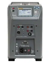
FLUKE 9144-B-156 Field Metrology Well with B Insert
User Manual for the Fluke 9144-B-156 Field Metrology Well with B Insert - Page 18
For 9144-B-156.
PDF File Manual
,
42 pages
,
Read Online
|
Download pdf file
1 Before You Start
1.1 Introduction
1.2 Unpacking
1.3 Symbols Used
1.4 Safety Information
1.4.1 Warnings
1.4.2 Cautions
1.5 CE Comments
1.5.1 EMC Directive
1.5.2 Immunity Testing
1.5.3 Emission Testing
1.5.4 Low Voltage Directive (Safety)
1.6 Authorized Service Centers
2 Specifications and Environmental Conditions
2.1 Specifications
2.2 Environmental Conditions
3 Quick Start
3.1 Setup
3.2 Parts and Controls
3.2.1 Display Panel
3.2.2 Display
3.2.3 Power Panel
3.2.4 -P Option Panel (-P models only)
3.3 Languages
3.3.1 Language Selection
3.3.2 Reset to English Language
4 Menu Structure
4.1 Temp Setup Menu
4.2 Prog Menu
4.2.1 Switch Test Parameters
4.2.2 Switch Test Description
4.3 System Menu
4.4 Input Setup (-P only)
5 Maintenance
5.1 Field Metrology Well Performance Analysis
Table 1 Symbols used
Table 2 Base Unit Specifications
Table 3 -P Option Specifications
Figure 1 Clamp-on ferrite installation
Figure 2 914X Field Metrology Well
Figure 3 Display panel and keys
Figure 4 914X display
Figure 5 9142 power panel
Figure 6 9143 and 9144 power panel
Figure 7 -P option panel
Figure 8 Probe connector wiring
Figure 9 Jumper locations for 3-wire and 2-wire connections
Figure 10 Steps to language selection
Figure 11 Main Menu - Temp SetUp
Figure 12 Main Menu - Prog Menu
Figure 13 Auto and manual switch test operation example
Figure 14 Main Menu - System Menu
Figure 15 Main Menu - Input Setup
Page 18/42
Page 1
Page 2
Page 3
Page 4
Page 5
Page 6
Page 7
Page 8
Page 9
Page 10
Page 11
Page 12
Page 13
Page 14
Page 15
Page 16
Page 17
Page 18
Page 19
Page 20
Page 21
Page 22
Page 23
Page 24
Page 25
Page 26
Page 27
Page 28
Page 29
Page 30
Page 31
Page 32
Page 33
Page 34
Page 35
Page 36
Page 37
Page 38
Page 39
Page 40
Page 41
Page 42
Contents
Table of Contents
Search
Previous
Next
Bookmarks
Loading ...
Loading ...
Loading ...
1.888.610.7664
sales@GlobalT
estSupply
.com
Fluk
e
-
D
ir
ect
.com
Loading ...
Loading ...
Loading ...
File type: PDF
File name: 12673448_9144-b-156.pdf
File size: 1.7 MB
File Language: English
Pages: 42
Author: FLUKE
Published: 2024-02-09
Updated: 2024-02-09
Download File
Table of Contents
×
1 Before You Start
7
1.1 Introduction
7
1.2 Unpacking
8
1.3 Symbols Used
9
1.4 Safety Information
10
1.4.1 Warnings
11
1.4.2 Cautions
13
1.5 CE Comments
14
1.5.1 EMC Directive
14
1.5.2 Immunity Testing
14
1.5.3 Emission Testing
15
1.5.4 Low Voltage Directive (Safety)
15
1.6 Authorized Service Centers
15
2 Specifications and Environmental Conditions
19
2.1 Specifications
19
2.2 Environmental Conditions
21
3 Quick Start
23
3.1 Setup
23
3.2 Parts and Controls
24
3.2.1 Display Panel
25
3.2.2 Display
26
3.2.3 Power Panel
28
3.2.4 -P Option Panel (-P models only)
30
3.3 Languages
32
3.3.1 Language Selection
32
3.3.2 Reset to English Language
33
4 Menu Structure
35
4.1 Temp Setup Menu
35
4.2 Prog Menu
36
4.2.1 Switch Test Parameters
37
4.2.2 Switch Test Description
37
4.3 System Menu
39
4.4 Input Setup (-P only)
40
5 Maintenance
41
5.1 Field Metrology Well Performance Analysis
41
Table 1 Symbols used
9
Table 2 Base Unit Specifications
19
Table 3 -P Option Specifications
20
Figure 1 Clamp-on ferrite installation
15
Figure 2 914X Field Metrology Well
24
Figure 3 Display panel and keys
26
Figure 4 914X display
27
Figure 5 9142 power panel
29
Figure 6 9143 and 9144 power panel
29
Figure 7 -P option panel
30
Figure 8 Probe connector wiring
31
Figure 9 Jumper locations for 3-wire and 2-wire connections
32
Figure 10 Steps to language selection
33
Figure 11 Main Menu - Temp SetUp
35
Figure 12 Main Menu - Prog Menu
36
Figure 13 Auto and manual switch test operation example
38
Figure 14 Main Menu - System Menu
39
Figure 15 Main Menu - Input Setup
40
Search:
×
Search