
100M or Gigabit Hi-PoE Switch
Quick Start Guide
UD17624B

Legal Informaon
©2019 Hangzhou Hikvision Digital Technology Co., Ltd. All rights
reserved.
About this Manual
The Manual includes instrucons for using and managing the
Product. Pictures, charts, images and all other informaon
hereinaer are for descripon and explanaon only. The
informaon contained in the Manual is subject to change,
without noce, due to rmware updates or other reasons. Please
nd the latest version of this Manual at the Hikvision website
( hps://www.hikvision.com/ ).
Please use this Manual with the guidance and assistance of
professionals trained in supporng the Product.
Trademarks
and other Hikvision's trademarks
and logos are the properes of Hikvision in various jurisdicons.
Other trademarks and logos menoned are the properes of
their respecve owners.
Disclaimer
TO THE MAXIMUM EXTENT PERMITTED BY APPLICABLE LAW, THIS
MANUAL AND THE PRODUCT DESCRIBED, WITH ITS HARDWARE,
SOFTWARE AND FIRMWARE, ARE PROVIDED “AS IS” AND “WITH
ALL FAULTS AND ERRORS”. HIKVISION MAKES NO WARRANTIES,
EXPRESS OR IMPLIED, INCLUDING WITHOUT LIMITATION,
MERCHANTABILITY, SATISFACTORY QUALITY, OR FITNESS FOR A
PARTICULAR PURPOSE. THE USE OF THE PRODUCT BY YOU IS AT
YOUR OWN RISK. IN NO EVENT WILL HIKVISION BE LIABLE TO YOU
FOR ANY SPECIAL, CONSEQUENTIAL, INCIDENTAL, OR INDIRECT
DAMAGES, INCLUDING, AMONG OTHERS, DAMAGES FOR LOSS OF
BUSINESS PROFITS, BUSINESS INTERRUPTION, OR LOSS OF DATA,
CORRUPTION OF SYSTEMS, OR LOSS OF DOCUMENTATION,
WHETHER BASED ON BREACH OF CONTRACT, TORT (INCLUDING
NEGLIGENCE), PRODUCT LIABILITY, OR OTHERWISE, IN
CONNECTION WITH THE USE OF THE PRODUCT, EVEN IF
HIKVISION HAS BEEN ADVISED OF THE POSSIBILITY OF SUCH
DAMAGES OR LOSS.
YOU ACKNOWLEDGE THAT THE NATURE OF INTERNET PROVIDES
FOR INHERENT SECURITY RISKS, AND HIKVISION SHALL NOT TAKE
ANY RESPONSIBILITIES FOR ABNORMAL OPERATION, PRIVACY
LEAKAGE OR OTHER DAMAGES RESULTING FROM CYBER-ATTACK,
HACKER ATTACK, VIRUS INSPECTION, OR OTHER INTERNET
SECURITY RISKS; HOWEVER, HIKVISION WILL PROVIDE TIMELY
TECHNICAL SUPPORT IF REQUIRED.
YOU AGREE TO USE THIS PRODUCT IN COMPLIANCE WITH ALL
APPLICABLE LAWS, AND YOU ARE SOLELY RESPONSIBLE FOR
ENSURING THAT YOUR USE CONFORMS TO THE APPLICABLE LAW.
ESPECIALLY, YOU ARE RESPONSIBLE, FOR USING THIS PRODUCT IN
A MANNER THAT DOES NOT INFRINGE ON THE RIGHTS OF THIRD
PARTIES, INCLUDING WITHOUT LIMITATION, RIGHTS OF
i

PUBLICITY, INTELLECTUAL PROPERTY RIGHTS, OR DATA
PROTECTION AND OTHER PRIVACY RIGHTS. YOU SHALL NOT USE
THIS PRODUCT FOR ANY PROHIBITED END-USES, INCLUDING THE
DEVELOPMENT OR PRODUCTION OF WEAPONS OF MASS
DESTRUCTION, THE DEVELOPMENT OR PRODUCTION OF
CHEMICAL OR BIOLOGICAL WEAPONS, ANY ACTIVITIES IN THE
CONTEXT RELATED TO ANY NUCLEAR EXPLOSIVE OR UNSAFE
NUCLEAR FUEL-CYCLE, OR IN SUPPORT OF HUMAN RIGHTS
ABUSES.
IN THE EVENT OF ANY CONFLICTS BETWEEN THIS MANUAL AND
THE APPLICABLE LAW, THE LATER PREVAILS.
ii
Regulatory
FCC
Please take that changes or not expressly
approved by the party responsible for compliance could void the
user's authority to operate the equipment.
FCC compliance: This equipment has been tested and found to
comply with the limits for a Class A digital device, pursuant to
part 15 of the FCC Rules. These limits are designed to provide
reasonable
against harmful interference when the
equipment is operated in a commercial environment. This
equipment generates, uses, and can radiate radio frequency
energy and, if not installed and used in accordance with the
manual, may cause harmful interference to radio
of this equipment in a
area is likely to cause harmful interference in which case the user
will be required to correct the interference at his own expense.
FCC
This device complies with part 15 of the FCC Rules. is
subject to the following two
1. This device may not cause harmful interference.
2. This device must accept any interference received, including
interference that may cause undesired
EU Conformity Statement
This product and - if applicable - the supplied accessories
too are marked with "CE" and comply therefore with the
applicable harmonized European standards listed under
the EMC
2014/30/EU, the RoHS 2011/
65/EU.
2012/19/EU (WEEE Products marked with this
symbol cannot be disposed of as unsorted municipal waste
in the European Union. For proper recycling, return this
product to your local supplier upon the purchase of
equivalent new equipment, or dispose of it at designated
points. For more see:
www.recyclethis.info .
2006/66/EC This product contains a
that cannot be disposed of as unsorted municipal
waste in the European Union. See the product
for The
is marked with this symbol, which may include
to indicate cadmium (Cd), lead (Pb), or mercury
(Hg). For proper recycling, return the
to your
supplier or to a designated
point. For more
see: .
iii

Industry Canada ICES-003 Compliance
This device meets the CAN ICES-3 (A)/NMB-3(A) standards
requirements.
iv

Preface
Applicable Models
This manual is applicable to DS-3T03XXHP series and
DS-3T05XXHP series switches.
Symbol Convenons
The symbols that may be found in this document are dened as
follows.
Symbol Descripon
Danger
Indicates a hazardous situaon which, if not avoided,
will or could result in death or serious injury.
Cauon
Indicates a potenally hazardous situaon which, if
not avoided, could result in equipment damage, data
loss, performance degradaon, or unexpected
results.
Note
Provides addional informaon to emphasize or
supplement important points of the main text.
v

Safety Instrucon
Cauon
•
During the installaon and ulizaon of the device, please
strictly conform to electrical safety rules in dierent naons
and regions.
•
Use the power adapter delivered with the device only.
•
The device can be directly or
modied to connect with IT
power distribuon system.
•
Please install the device in accordance with the installaon
method in the manual.
•
Do not place any naked ame sources, such as lit candles, on
the device.
•
Do not place any objects containing water or liquids on the
device. Prevent the device from water dropping or splashing.
•
The device must be installed in machine room or machine
cabinet only, and only maintenance
sta or qualied person
can access to the device.
•
Do not touch the cover area of the device that may be
overheated.
Danger
•
Please x the device in a stable posion. Otherwise, serious
personal injury or casuales may happen if the device is
dumped.
•
The supporng accessories can only be used together with the
device. Using them with other device may cause instability and
injury.
•
The device must be
rmly xed on the DIN rail or wall to
prevent injury.
•
Place the device out of reach of kids.
•
The power socket or power plug is used to disconnect power.
Do not cover the power socket or power plug so that it can be
easily moved.
•
The device has mulple power supplies. To avoid electric
shock, please disconnect all power supplies during
maintenance.
•
This is a class A product and may cause radio interference in
which case the user may be required to take adequate
measures.
•
If the product does not work properly, please contact your
dealer or the nearest service center. Never
aempt to
disassemble the product yourself. (We shall not assume any
responsibility for problems caused by unauthorized repair or
maintenance.)
vi
1 Introducon
1.1 Product Introducon
DS-3T03XXHP series and DS-3T05XXHP series switches are layer 2
Hi-PoE switches, providing advanced PoE power supply
technology and wider temperature (-30 to 65 °C, that is, -22 to
149 °F) design on the basis of high-performance access to ensure
stable data upload. The switches support Hi-PoE, long range, port
isolaon, and PoE watchdog funcon.
1.2 Packing List
DS-3T03XXHP Series DS-3T05XXHP Series
Switch × 1 × 1
Power Adapter × 1 × 1
AC Power Cord × 1 × 1
Wall Mount Ear × 2 × 2
DIN Rail Mount Clip × 2 × 2
Screw × 6 × 6
Quick Start Guide × 1 × 1
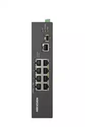
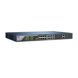
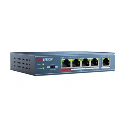
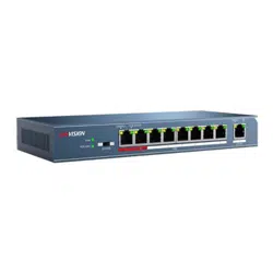
1.3 Appearance
Dierent models of devices may have dierent appearances. The
following pictures are only for illustraon.
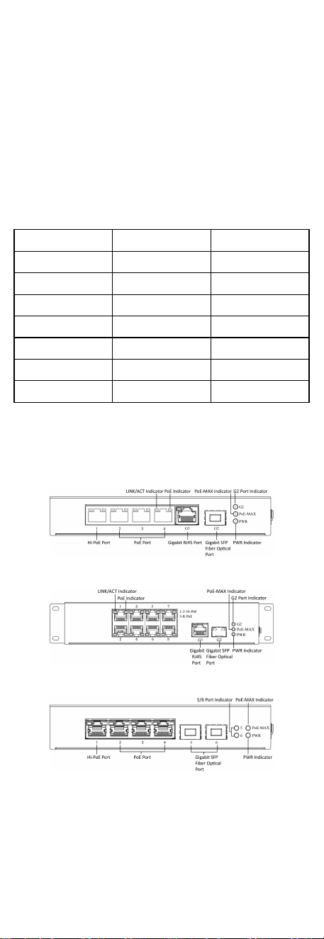
Front Panel
Figure 1-1 DS-3T0306HP-E
Figure 1-2 DS-3T0310HP-E
Figure 1-3 DS-3T0506HP-E
1
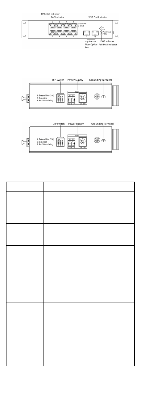
Figure 1-4 DS-3T0510HP-E
Rear Panel
Figure 1-5 DS-3TXX06HP-E Series
Figure 1-6 DS-3TXX10HP-E Series
Port/Indicator Descripon
Indicator/Port Descripon
PoE-MAX Indicator
•
Solid /Flashing: The output power of the switch
will reach the upper limit. The power supply may
be abnormal if more devices are connected.
•
Unlit: The switch provides power supply to PD
normally.
PWR Indicator
•
Solid: The switch is powered on normally.
•
Unlit: No power supply connected or power
supply is abnormal.
LINK/ACT Indicator
•
Solid: The port is connected.
•
Flashing: The port is transming data.
•
Unlit: The port is disconnected or connecon is
abnormal.
PoE Indicator
•
Solid: The switch provides power supply to PD
normally.
•
Unlit: The switch is disconnected to PD, or
provides power supply to PD abnormally.
G2/5/6/9/10 Port
Indicator
•
Solid: The gigabit SFP ber opcal port is
connected.
•
Flashing: The gigabit SFP ber opcal port is
transming data.
•
Unlit: No gigabit SFP ber opcal port connected
or connecon is abnormal.
Hi-PoE Port
Used for other Hi-PoE PTZ cameras connecon. In
the temperature from 0 to 40 °C (32 to 104 °F), the
max. power of DS-3TXX06HP series is 60 W, and the
max. power of DS-3TXX10HP series is 90 W.
2

PoE Port
Used for other PD devices connecon via network
cables.
Gigabit RJ45 Port Used for devices connecon via network cables.
Gigabit SFP Fiber
Opcal Port
Used for other devices connecon via opcal ber
when plugged into with an opcal module.
Grounding Terminal
Used for connecng to the grounding cable to
protect the switch from lightning.
Power Supply
Use the aached power cord to connect the switch
to socket.
DIP Switch
Support 3 modes:
•
Extend: Port 3 and 4 of DS-3TXX06HP-E series and
port 7 and 8 of DS-3TXX10HP-E series support
network transmission of up to 300 metres.
•
Isolaon: Data transmission of each port is
isolated from each other to improve network
security.
•
PoE Watchdog: Auto-detect and restart cameras
that do not respond.
2 Installaon
Please select the appropriate installaon method according to
the actual needs.
Before You Start
•
Keep the room well-venlated.
•
Keep at least 10 cm distance around the device for heat
dissipaon.
2.1 Wall-Mounted Installaon
Before You Start
Use a screwdriver to remove the DIN rail-mounted unit.
Steps
1.
Fix the wall mount ears to the device with self-prepared M4
screws.
2.
Use self-prepared M4 screws to
x the device onto the wall.
Figure 2-1 Wall-Mounted Installaon
3
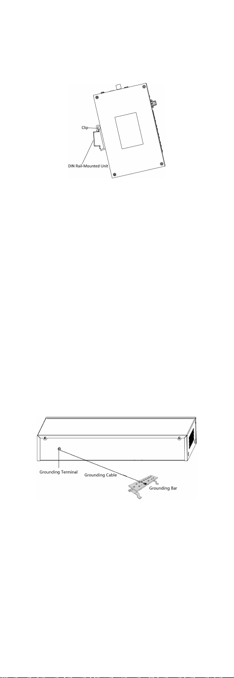
2.2 Rail-Mounted Installaon
Steps
1.
Fix the clip to the device.
2.
Insert the end of DIN rail-mounted unit into the notch under
the clip.
Figure 2-2 Rail Mounted Installaon
3.
Press the DIN rail-mounted unit in quickly.
3 Grounding
3.1 Connecng the Grounding Cable
Grounding is used to quickly release overvoltage and overcurrent
induced by lightening for switch, and to protect personal safety.
Select the appropriate grounding method according to your
needs.
3.1.1 With Grounding Bar
If a grounding bar is available at the installaon site, follow the
steps below.
Steps
1.
Connect one end of the grounding cable to the binding post on
the grounding bar.
2.
Connect the other end of the grounding cable to the grounding
terminal of the device and
x the screw.
Figure 3-1 Grounding with Grounding Bar
3.1.2 Without Grounding Bar
If there is no grounding bar but the earth is nearby and the
grounding body is allowed to be buried, follow the steps below.
Steps
1.
Bury an angle steel or steel pipe (≥ 0.5 m) into the mud land.
4
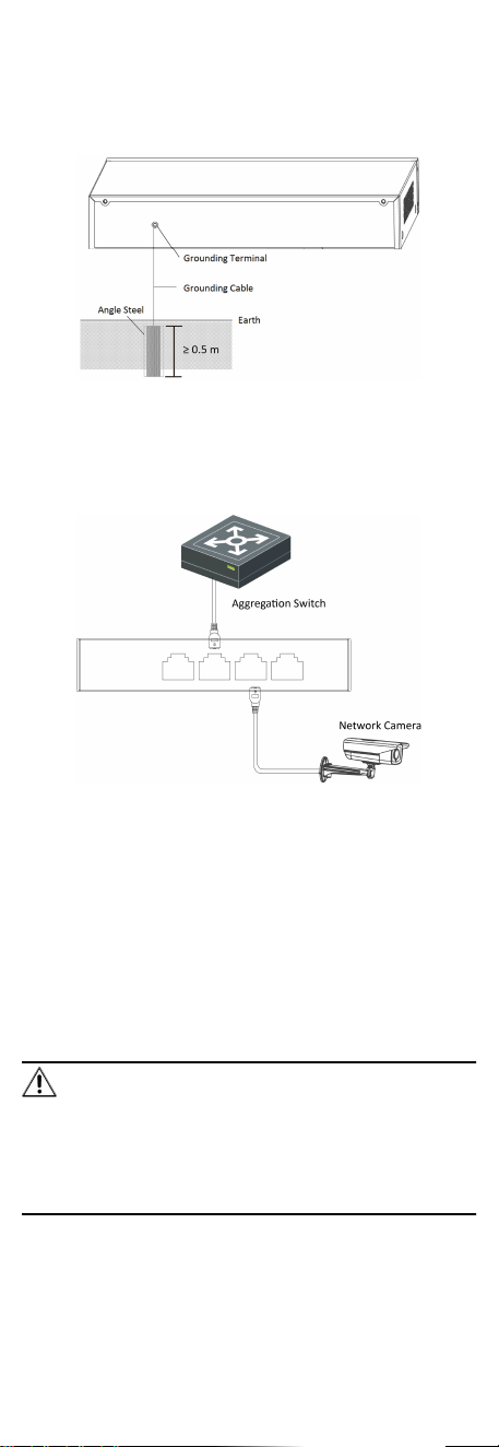
2.
Weld one end of the grounding cable to the angle steel or steel
pipe and embalm the welding point via electroplang or
coang.
3.
Connect the other end of the grounding cable to the grounding
terminal.
Figure 3-2 Grounding with Angle Steel
3.2 Connecng RJ45 Port
Use a network cable to connect the device to the RJ45 port of a
peer device such as network camera, NVR, switch, etc.
Figure 3-3 RJ45 Port Connecon
3.3 Connecng SFP Opcal Module
Connecng SFP opcal module is supported when the device has
a
ber opc port or a combo.
When connected to a network cable, the combo is a RJ45 port.
When plugged into with an opcal module and connected to an
opcal ber, the combo funcons as a ber opc port.
When connected to both the network cable and
opcal ber at
the same
me, the port works as a ber opc port.
Steps
Cauon
•
Single-Mode opcal module needs to be paired.
•
Do not bend ber opc (curvature radius ≥ 10 cm) overly.
•
Do not look directly at ber opc connector because the laser
is harmful to eyes.
1.
Connect the two paired SFP opcal modules with an opcal
ber.
5

2.
Hold the SFP opcal module from one side, and smoothly plug
it into the device along with the SFP port slot unl the opcal
module and the device are closely aached.
3.
Aer powering on the device, check the status of LINK/ACT
indicator. If the indicator is lit, the link is connected. If the
indicator is unlit, the link is disconnected. Check the line, and
make sure peer devices have been started.
4 Powering on the Device
Please use the
aached power cord in package to power on the
device.
Before powering your switch, make sure that:
•
The operang power supply is compliant with rated input
standard.
•
Port cables and grounding cables are correctly connected.
•
If there is outdoor cabling, connect a lightning rod and
lightening arrester to the cable.
Cauon
PoE power supply line and strong wire cannot be wired together,
otherwise PD equipment or switch ports will be burnt.
6