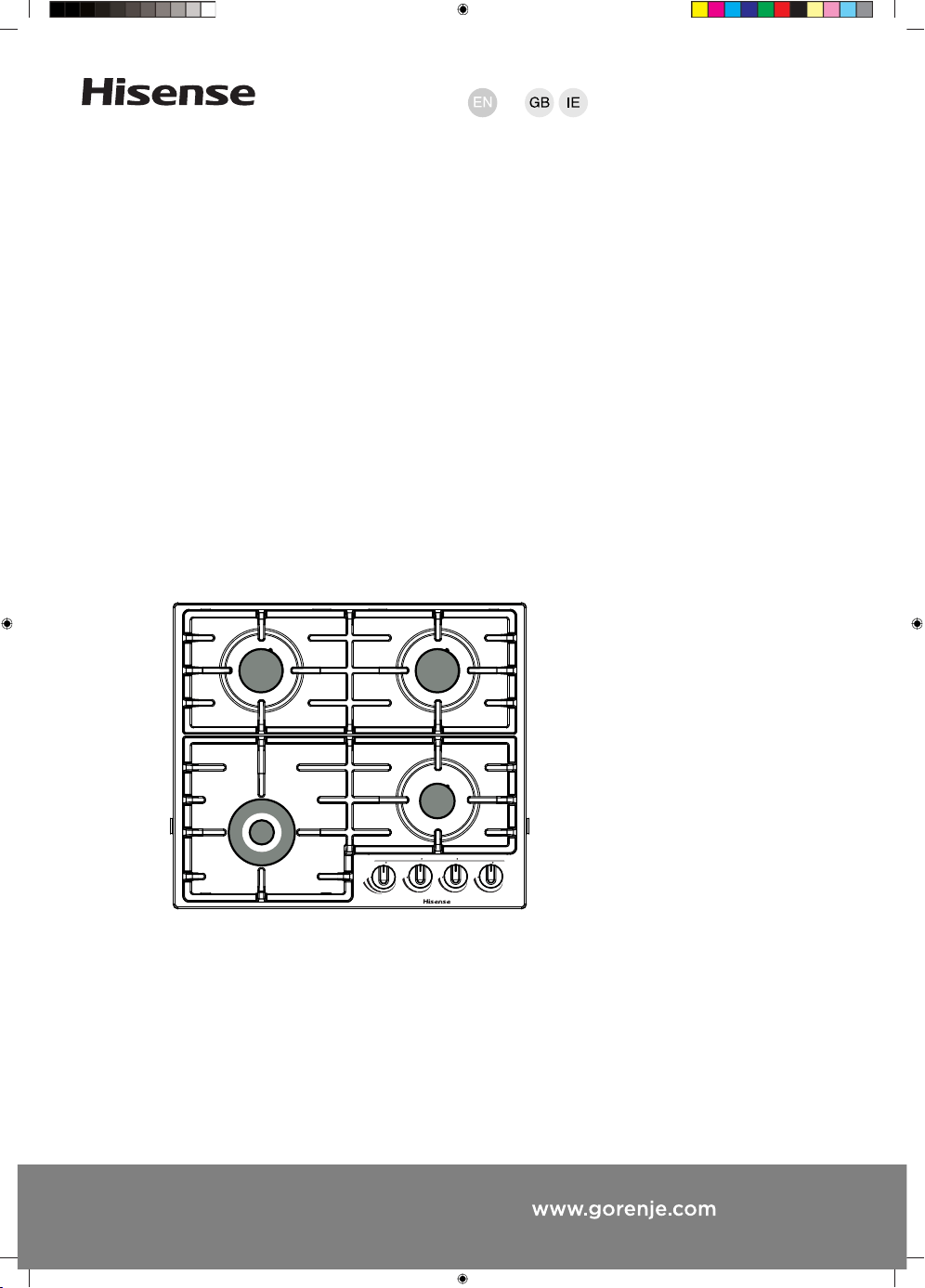
Gas Hobs
User manual
Installation instruction
Conversion instruction
BG3xA - BG6xA - BG6xB - BG6xD
BG6xE - BG7xA - BG7xB - BG7xC
BG7xD - BG9xA - BG9xB - BG9xD
BG9xE
The following symbols are used throughout the manual and they have the following meanings:
INFORMATION!
Information, advice, tip, or recommendation
WARNING!
Warning – general danger
GAS CONNECTION!
Warning – gas connection
ELECTRIC SHOCK!
Warning – danger of electric shock
HOT SURFACE!
Warning – danger of hot surface
DANGER OF FIRE!
Warning – danger of fire
RIGHT!
WRONG!
It is important that you carefully read the instructions.

Contents
4Safety regulations ...................................................................................................................
4READ CAREFULLY AND KEEP FOR FUTURE REFERENCE! ..................................................
7Gas hob ....................................................................................................................................
9User Manual ............................................................................................................................
9Models ......................................................................................................................................
11Description ................................................................................................................................
12Information according to regulation (EU only) 66/2014 ............................................................
13Use ............................................................................................................................................
14Burner position: ........................................................................................................................
14Cleaning: ...................................................................................................................................
15Faults table ...............................................................................................................................
16Installation instruction ............................................................................................................
16Safety regulations .....................................................................................................................
19Preparations for installation ......................................................................................................
20Sealing tape ..............................................................................................................................
21Gas connection .........................................................................................................................
21Accessibility ..............................................................................................................................
22Built-in .......................................................................................................................................
22Connecting & testing ................................................................................................................
23Conversion instruction ...........................................................................................................
23Conversion table .......................................................................................................................
24Power table (kW-g/h): ...............................................................................................................
25Converting nozzles ...................................................................................................................
25Converting by-pass screws ......................................................................................................
26Check for gas tightness and operation .....................................................................................
26Start up .....................................................................................................................................
26Checking operation ...................................................................................................................
27Environmental considerations ...............................................................................................
27Disposal of the appliance and packaging .................................................................................
3
Safety regulations
READ CAREFULLY AND KEEP FOR FUTURE REFERENCE!
General
•
The manufacturer cannot be held liable for any damage
resulting from failure to follow the safety instructions and
warnings.
•
Damage caused by incorrect connection, incorrect fitting,
or incorrect use is not covered by the warranty.
WARNING!
This appliance and the accessible parts will become hot
during use. Do not touch hot parts. Keep children younger
than 8 away from the appliance unless they are under
continuous supervision.
DANGER OF FIRE!
WARNING: Danger of fire: do not store items on the cooking
surfaces.
•
CAUTION! The cooking process has to be supervised. A
short term cooking process has to be supervised
continuously.
DANGER OF FIRE!
WARNING: Cooking with fat or oil on a hob without
supervision can be dangerous and can lead to a fire.
4
•
NEVER try to extinguish a fire with water. Instead, switch the
appliance off and then cover the flames with for example a
lid or a fire blanket.
•
Never flambé under a cooker hood. The high flames can
cause a fire, even if the cooker hood is switched off.
WARNING!
Use only hob guards designed by the manufacturer of the
cooking appliance or indicated by the manufacturer of the
appliance in the instructions for use as suitable or hob
guards incorporated in the appliance. The use of
inappropriate guards can cause accidents.
•
The hob is only to be used for the preparation of food.
•
The unit is not designed for heating rooms.
•
Do not warm closed tins on the hob. There will be a build-up
of pressure that will cause tins to explode. You might get
injured or scalded.
•
Never cover the appliance with a cloth or something similar.
If the appliance is still hot or is switched on, there is a risk
of fire.
•
Do not use the appliance as a worktop. The appliance may
accidentally be switched on or still be hot, which means
objects could melt, become hot or catch fire.
•
Do not use the appliance in temperatures below 5 °C.
•
The appliance should not be placed or used outdoors.
5
•
When you use the hob for the first time you will notice a “new
smell”. Don’t worry, this is normal. If the kitchen is well
ventilated, the smell will soon disappear.
•
The appliance is not intended to be operated by means of
an external timer or separate remote control system.
•
Never open the casing of the appliance.
•
Never use a pressure cleaner or steam cleaner to clean the
hob.
•
The ceramic top is extremely strong, but not unbreakable.
For example, a spice jar or sharp utensil falling on it could
cause it to break.
•
If a drawer underneath the appliance is permitted (see the
installation instructions), without an intermediate bottom,
this should not be used to store highly flammable
objects/materials. Ensure that there is adequate clearance
of a few centimetres between the bottom of the hob and the
contents of any drawers.
ELECTRIC SHOCK!
WARNING! In case of hotplate glass breakage:
•
shut immediately off all burners and any electrical heating
element and isolate the appliance from the power supply.
•
do not touch the appliance surface.
•
do not use the appliance.
6
WARNING!
•
This appliance can be used by children aged 8 years and
over, as well as by people with reduced physical, sensory
or mental capabilities or lack of experience and
knowledge, provided they are supervised and instructed
in the safe use of the appliance and understand the
hazards involved.
•
Do not allow children to play with the appliance.
•
Do not allow children to clean or maintain the appliance
unless supervised.
•
Do not keep objects that children might find interesting
in cupboards above or behind the appliance.
•
The cooking zones/burners heat up during use and stay
hot for a while afterwards. Keep young children away
from the hob during and immediately after cooking.
Gas hob
•
CAUTION! The use of a gas cooking appliance results in the
production of heat, moisture and products of combustion in
the room in which it is installed. Ensure that the kitchen is
well ventilated especially when the appliance is in use. Keep
natural ventilation holes open or install a mechanical
ventilation device (mechanical extractor hood).
•
The burner components are hot during and immediately after
use. Do not touch them, and avoid contact with non-heat
resistant materials.
7

•
Never immerse hot burner caps and pan supports in cold
water. The rapid cooling can damage the enamel.
•
The distance between the pan and a knob or non-heat
resistant wall should always be greater than one centimetre.
In case of smaller distances, the high temperature may cause
the knobs or wall to discolour and/or deform.
•
Always use the pan supports and suitable cookware.
•
Always place the pan on the pan support. Placing the pan
directly on the burner cap can result in dangerous situations.
•
Aluminium trays or foil are not suitable as cooking utensils.
They can burn into the burner caps and pan supports.
•
The hob can only function effectively if the burner
components have been assembled using the guide ridges.
Ensure that the pan supports lie properly against each other
and flat on the drip tray. Only then can the pans be positioned
stably.
•
Keep oven gloves or oven cloths away from the flame.
•
Do not use griddle plates or baking plates.
•
Clean the burner parts regularly for safe and correct operation
of the burners.
•
Missing rubber feet from the pan supports can cause
scratches on the drip tray or poor combustion of the burner.
If the rubber feet are missing, please contact our service
department.
8
User Manual
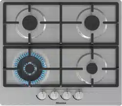
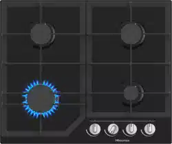
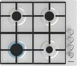
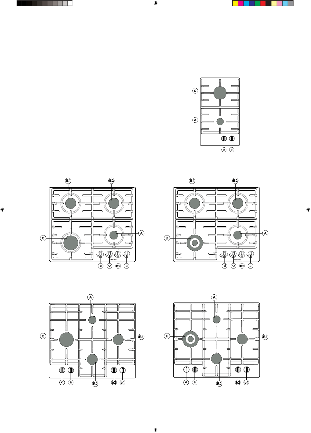
Models
BG3xA
Aa - Auxiliary burner
Bb - Semi-rapid burner
Cc - Rapid burner
Dd - Wok burner
BG6xBBG6xA
BG6xEBG6xD
9
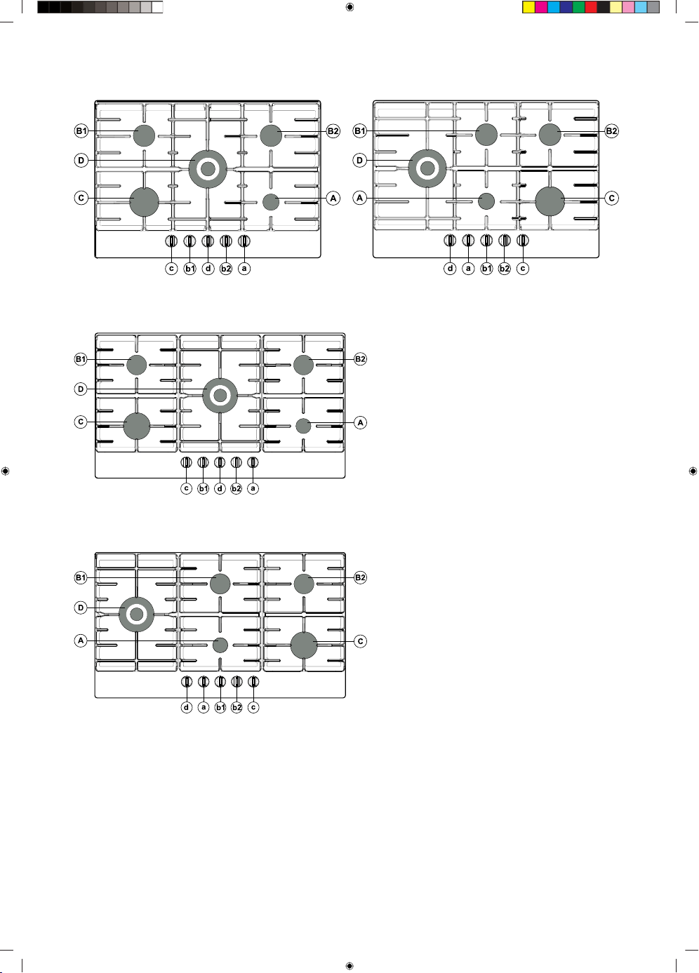
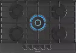
BG7xB / BG7xDBG7xA / BG7xC
BG9xA / BG9xD
BG9xB / BG9xE
10
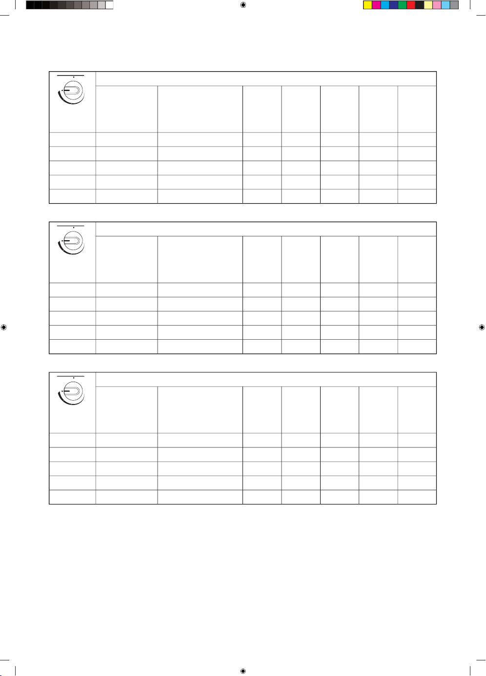
Description
G20 - 20 mbar
BG7XC
BG7xD
BG7xA
BG7xB
BG6xB
BG6xE
BG6xA
BG6xD
BG3xAPowerBurner
BG9xD
BG9xE
BG9xA
BG9xB
xxxxx1.05 kWAuxiliaryAa
xxxx1.80 kWSemi-rapidBb
xxxx3.00 kWRapidCc
xx3.50 kWWokDd
x4.05 kWWokDd
G30/G31 - 28-30/37 mbar
BG7xC
BG7xD
BG7xA
BG7xB
BG6xB
BG6xE
BG6xA
BG6xD
BG3xAPower / Mass flowBurner
BG9xD
BG9xE
BG9xA
BG9xB
xxxxx1.05 kW / 76 g/hAuxiliaryAa
xxxx1.70 kW / 122 g/hSemi-rapidBb
xxxx3.00 kW / 216 g/hRapidCc
xx3.50 kW / 252 g/hWokDd
x3.90 kW / 281 g/hWokDd
G30/G31 - 50 mbar
BG7xC
BG7xD
BG7xA
BG7xB
BG6xB
BG6xE
BG6xA
BG6xD
BG3xAPower / Mass flowBurner
BG9xD
BG9xE
BG9xA
BG9xB
xxxxx1.00 kW / 72 g/hAuxiliaryAa
xxxx1.90 kW / 137 g/hSemi-rapidBb
xxxx3.00 kW / 216 g/hRapidCc
xx3.50 kW / 252 g/hWokDd
x4.00 kW / 288 g/hWokDd
11
G20 - 25 mbar
BG7xC
BG7xD
BG9xD
BG9xE
BG6xB
BG6xE
BG6xA
BG6xD
BG3xAPower / Mass flowBurner
xxxx1.15 kWAuxiliaryAa
xxx2.00 kWSemi-rapidBb
xxx3.30 kWRapidCc
xx3.90 kWWokDd
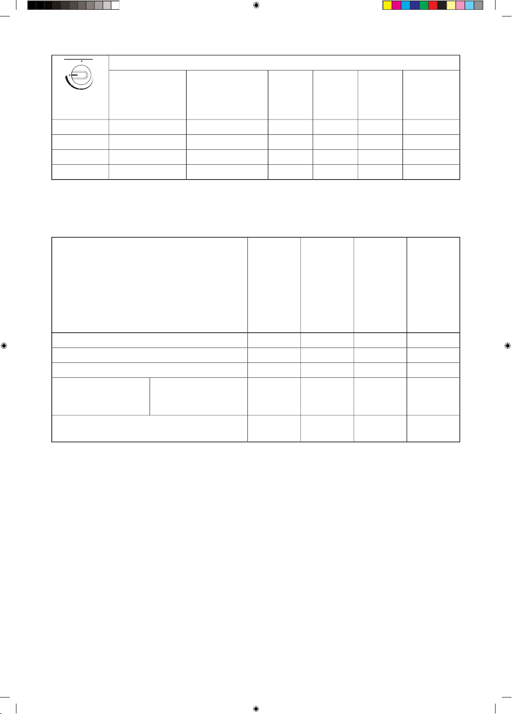
Information according to regulation (EU only) 66/2014
Measurements according to EN60350-2
BG7xA
BG7xB
BG7xC
BG7xD
BG9xA
BG9xB
BG9xD
BG9xE
BG6xB
BG6xE
BG6xA
BG6xD
BG3xAModel identification
Gas hobGas hobGas hobGas hobType of hob
5442Number of gas burners
Gas burnerGas burnerGas burnerGas burnerHeating technology
58.158.158.1-Semi-rapid burner:Energy efficiency per
gas burner (EEgas
burner) in %
57.1
55.1
-
55.1
57.1
-
57.1
-
Rapid burner:
Wok burner:
57.157.157.857.1Energy efficiency for the gas hob (EEgas
hob) in %
12
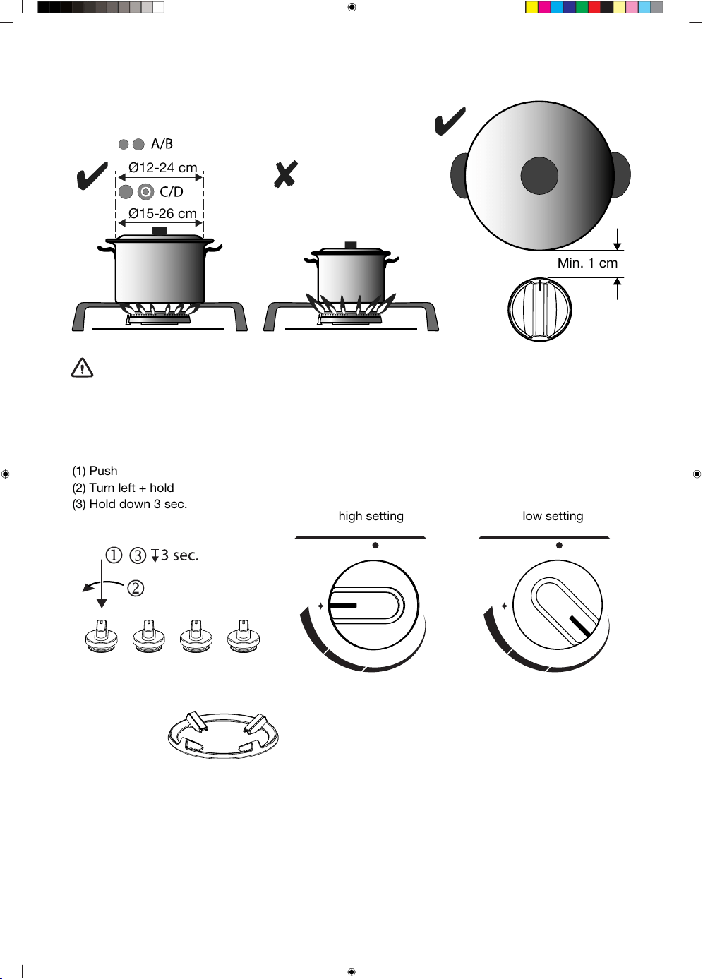
Use
Ø12-24 cm
Ø15-26 cm
Min. 1 cm
WARNING!
The distance between the pan and a non-heat resistant wall should always be greater than one
centimetre. In case of smaller distances, the high temperature may cause the knobs or wall to
discolour and/or deform.
Control:
(1) Push
(2) Turn left + hold
(3) Hold down 3 sec.
high setting low setting
Accessories:
Suits wok burner
806206
13
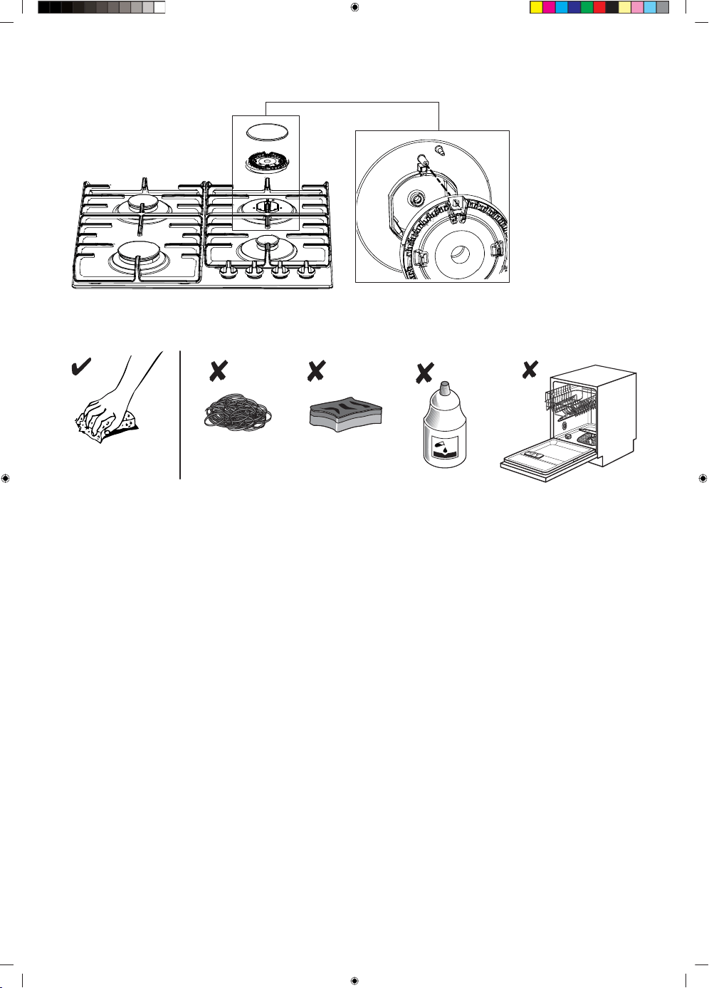
Burner position:
Cleaning:
14
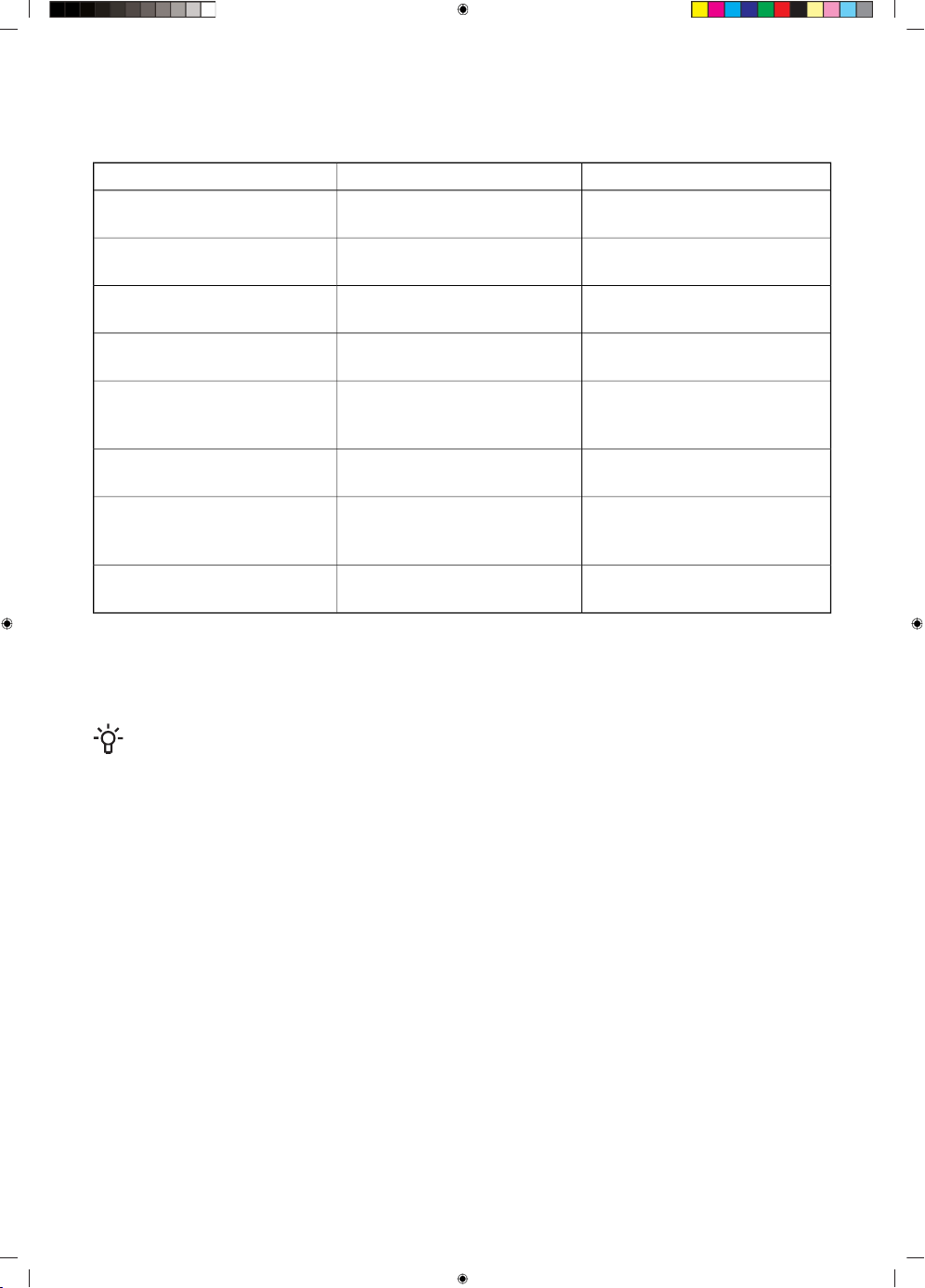
Faults table
Following is some advice on rectifying some common problems.
What to do?Possible causeWhat happened...?
Have an expert check the gas
pipeline!
The flame is uneven due to a
wrong gas power setting.
The burners will not burn.
The flame is uneven/unstable.
Assemble the burner correctly.Wrongly assembled parts of the
kitchen hob.
The flame from the burners
suddenly changes.
Assemble the burner correctly.Wrongly assembled parts of the
kitchen hob.
Burner ignition takes more time.
Keep the knob pressed for a
longer period of time.
Knob pressed too short or too
weakly.
The flame is extinguished
shortly after ignition.
Clean the grid with a metal care
detergent.
This is a commonplace phe-
nomenon resulting from high
temperature.
The grid has discoloured in the
burner area?
Check the fuse in the fuse box
and replace it if it is blown.
The fuse may be blown.Electric power supply, in gener-
al, is interrupted?
Open and carefully clean the
opening between the spark plug
and the burner.
There are food or detergent
residues between the spark
plug and the burner.
Electric ignition of the burners
no longer works?
Clean the burner covers with a
metal care detergent.
Regular dirt.The burner cover looks unap-
pealing.
A visit by a service technician during the warranty period will be charged if the appliance is not
functioning because of improper use. Store these instructions in a place where they are always readily
accessible; if you pass the appliance on to another person, the instructions should also be included.
NOTE!
If the problem persists despite observing the instructions above, call an authorized service
technician. Elimination of any errors or warranty claims that resulted from an improper connection
or use of the appliance is not covered by our warranty. In such cases, the costs of repair are
borne by the user.
15
Installation instruction
Safety regulations
•
This appliance should only be connected by a registered
installer.
•
Prior to installation, ensure that the local distribution
conditions (voltage, frequency, nature of the gas and gas
pressure) and the adjustment of the appliance are
compatible.
•
This appliance must be earthed.
•
The voltage, frequency, power, type of gas and the country
for which the appliance has been designed are shown on
the appliance rating plate.
•
Electrical connection Class I - 220-240 V - 50/60 Hz -
max 1 W.
•
The electrical connection must comply with national and
local regulations.
•
The wall plug socket and plug should always be accessible.
16
•
If a stationary appliance is not fitted with a supply cord and
a plug, or with other means for disconnection from the supply
mains having a contact separation in all poles that provide
full disconnection under overvoltage category III conditions,
the means for disconnection must be incorporated in the
fixed wiring in accordance with the wiring rules. Using an
omnipolar switch with a contact separation of at least 3 mm
fitted in the supply cable will fulfil this requirement.
•
The connection cable must hang freely and should not be
fed through a drawer.
•
Gas connection 1/2” ISO 228 / ISO 7-1 / EN 10226-1
(1/2” ISO 228 / 1/2” ISO 228 FR only).
The gas connection must comply with national and local
regulations. See appliance label for technical gas data.
•
This appliance is not connected to a combustion products
evacuation device. It shall be installed and connected in
accordance with current installation regulations. Particular
attention shall be given to the relevant requirements regarding
ventilation.
•
We recommend that the gas hob be connected by means
of a fixed pipe. Connection using a specially designed safety
hose is also permitted.
•
The pipe behind the oven must be made entirely out of metal.
•
A safety hose may not be bent and must not come into
contact with moving parts of kitchen units.
17
•
The gas supply valve must always be placed in an easily
accessible position.
•
The worktop into which the hob is fitted should be flat.
•
The walls and the worktop surrounding the appliance must
be heat resistant up to at least 85 °C. Even though the
appliance itself does not get hot, the heat of a hot pan could
discolour or deform the wall.
Service
•
Faulty parts may only be replaced by original parts.
The manufacturer can only guarantee that original parts meet
safety requirements.
•
If the supply cord is damaged, it must be replaced by the
manufacturer, its service agent or similarly qualified persons
in order to avoid a hazard.
18
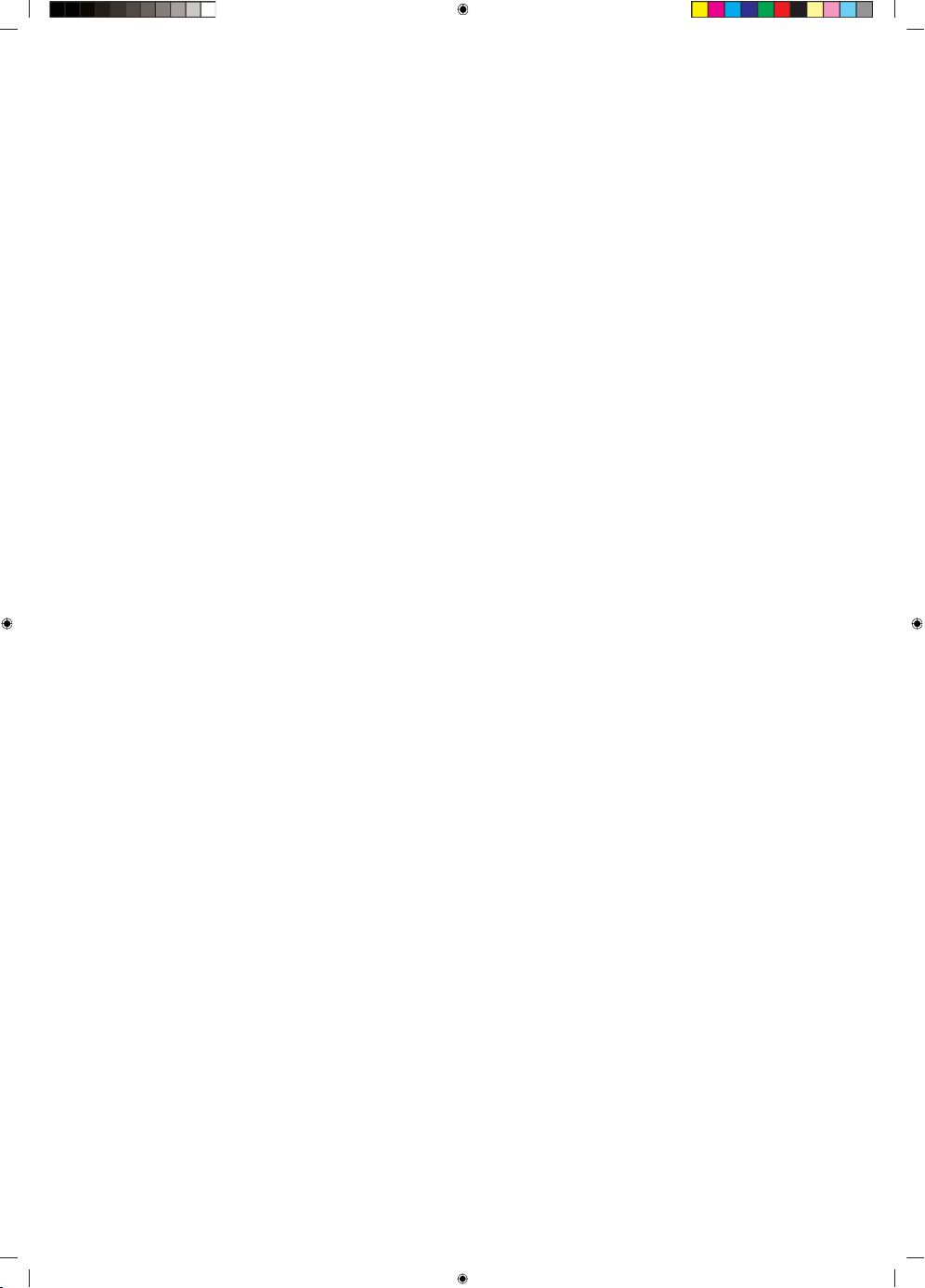
Preparations for installation
Free space around the appliance
D (mm)C (mm)B (mm)A (mm)
min. 120min. 450min. 600min. 650BG3
min. 120min. 450min. 600min. 650BG6
min. 120min. 450min. 750min. 650BG7
min. 120min. 450min. 900min. 650BG9
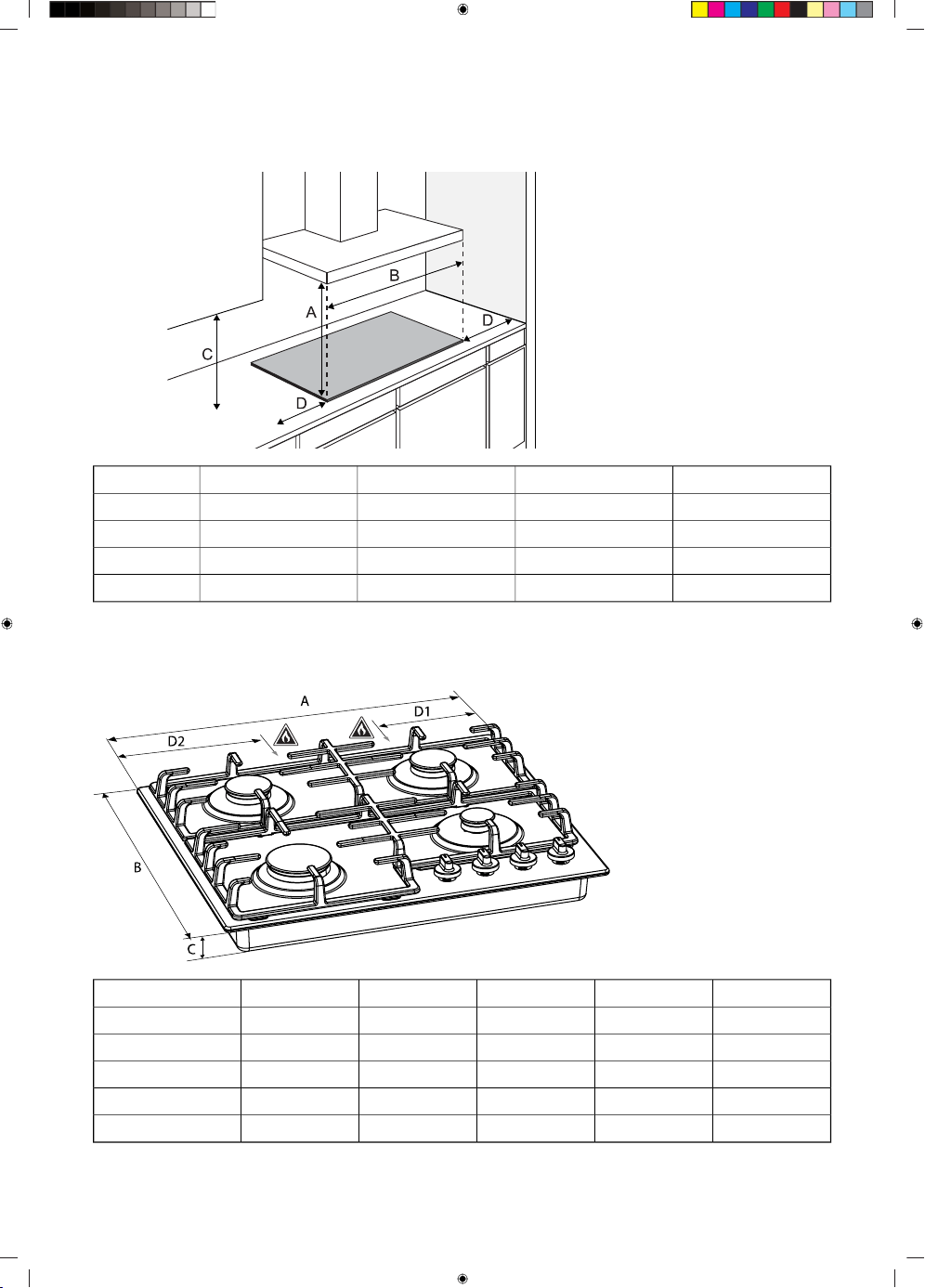
Dimensions
Appliance:
D2 (mm)D1 (mm)C (mm)B (mm)A (mm)
138-52520300BG3
138-52520600BG6xA/B
-13852520600BG6xD/E
-13852520750BG7
-13852520900BG9
19
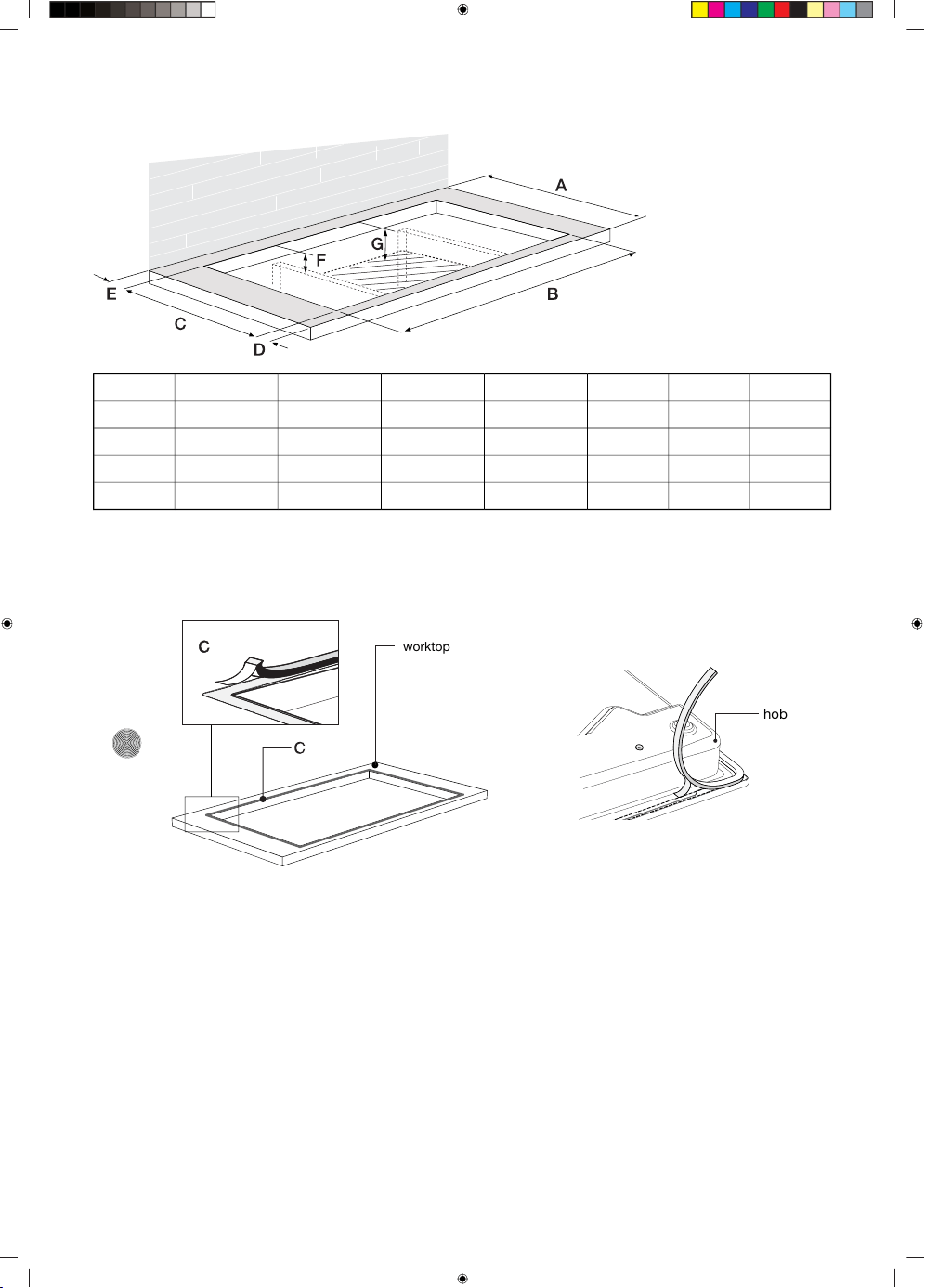
Built-in:
G (mm)F (mm)E (>mm)D (mm)C (mm)B (mm)A (mm)
100905060490260600BG3
100905060490560600BG6
100905060490715600BG7
100905060490860600BG9
Sealing tape
Glass drip trayStainless steel drip tray
hob
worktop
20
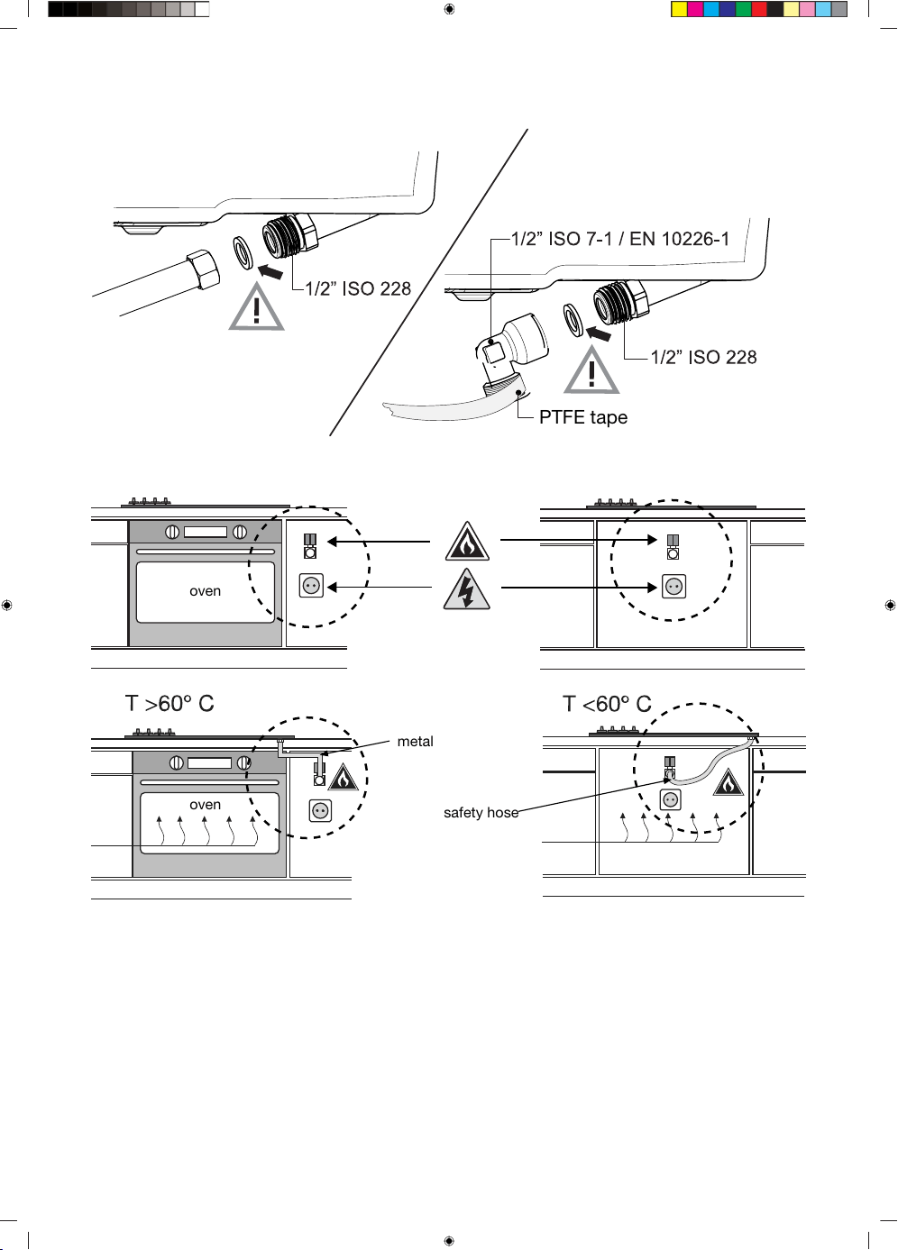
Gas connection
PTFE tape
Accessibility
oven
oven
metal
safety hose
21
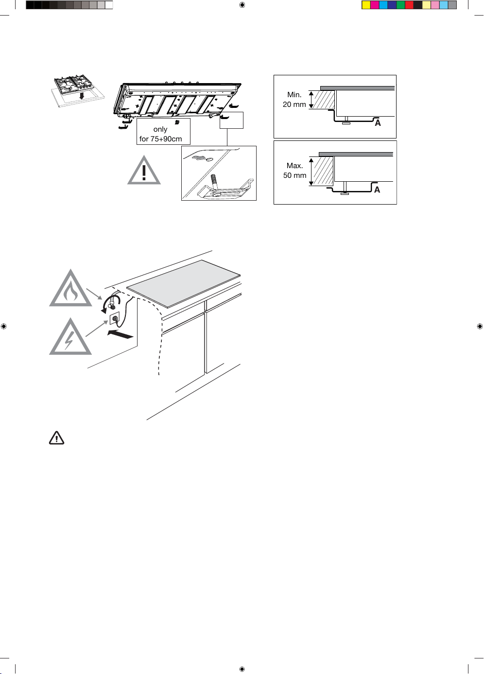
Built-in
only
for 75+90cm
Min.
20 mm
Max.
50 mm
Connecting & testing
WARNING!
Check if connections are gastight.
22
Conversion instruction
WARNING!
Adjusting for a different gas type!
WARNING!
Attention! Performing these instructions by a non-qualified person can lead to dangerous
situations. The supplier is not responsible for the consequences (the arising of a hazardous
situation and/or damage to persons or goods) caused by the incorrect performance of these
instructions by engineers who are not employees of the supplier. Consequential damage arising
through inexpert performance of these instructions is not accepted.
With this conversion-set, your gas hob can be converted to different gasses. See the conversion table.
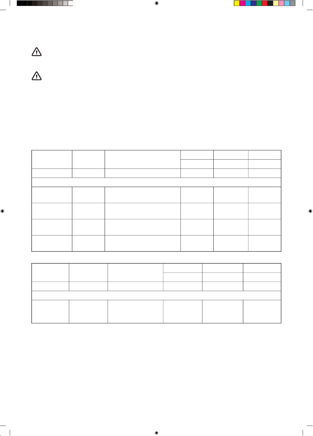
Conversion table
RapidSemi rapidAuxiliaryModificationP mbarGas type
nozzlenozzlenozzle
1289772-20 / 25G20
Convert from G20 - 20 mbar to:
14511584Replace nozzle & no action
bypass
13G20
856550Replace nozzle & screw in
bypass (see 3A)
28-30/37G30/G31
856550Replace nozzle & screw in
bypass (see 3A)
37(PL)
G30/G31
756043Replace nozzle & screw in
bypass (see 3A)
50G30/G31
RapidSemi rapidAuxiliaryModificationP mbarGas type
nozzlenozzlenozzle
856550-28-30/37G30/G31
Convert from G30/G31 - 28-30/37 mbar to:
1289772Replace nozzle &
adjust bypass (see
3C)
20 / 25G20
23
Wok
BG7xA/B /
BG9xA/B
Wok
BG6xB/E /
BG7xC/D /
BG9xD/E
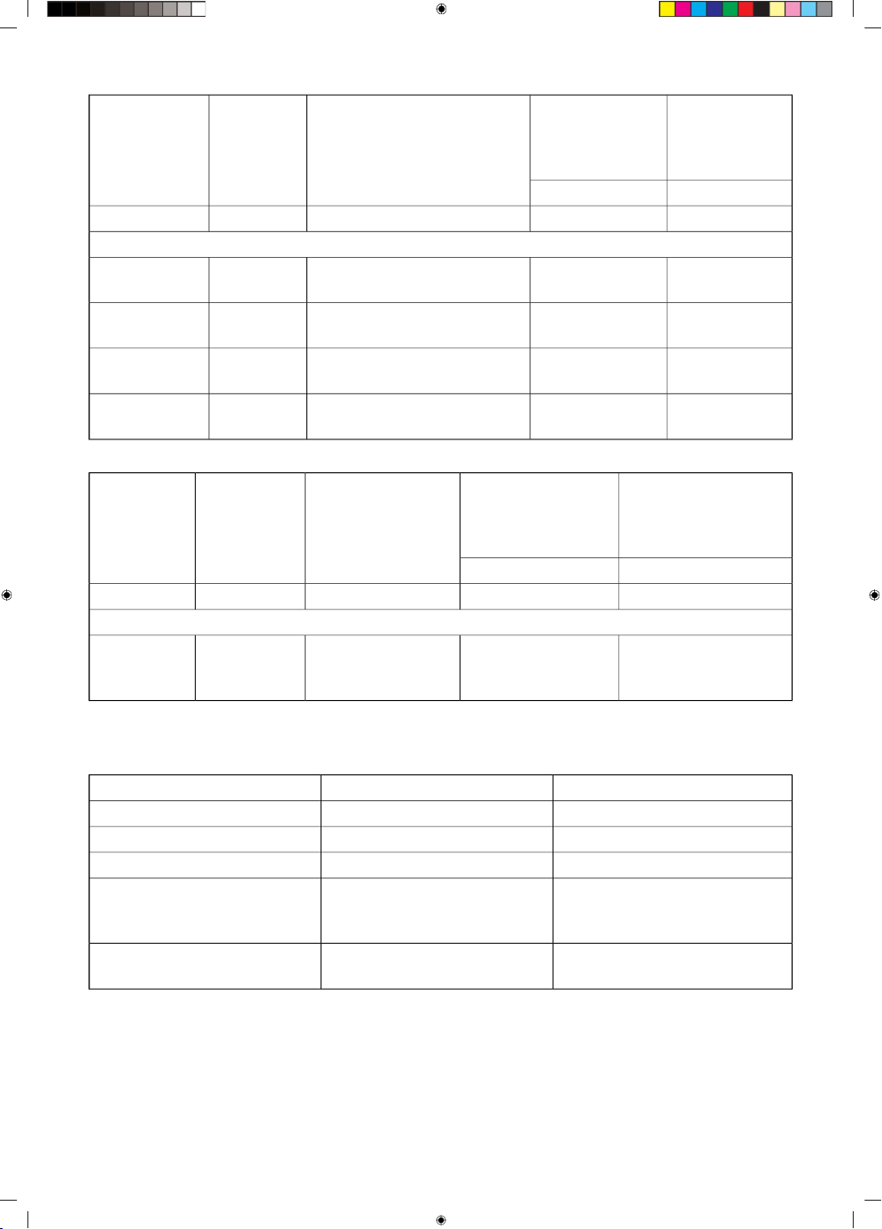
ModificationP mbarGas type
nozzlenozzle
150142-20 / 25G20
Convert from G20 - 20 mbar to:
170155Replace nozzle & no action
bypass
13G20
10094Replace nozzle & screw in by-
pass (see 3A)
28-30/37G30/G31
9494Replace nozzle & screw in by-
pass (see 3A)
37(PL)
G30/G31
9082Replace nozzle & screw in by-
pass (see 3A)
50G30/G31
WokWokModificationP mbarGas type
BG7xA/B / BG9xA/BBG6xB/E /
BG7xC/D /
BG9xD/E
nozzlenozzle
10094-28-30/37G30/G31
Convert from G30/G31 - 28-30/37 mbar to:
150 (not for G20 25
mbar)
142Replace nozzle &
adjust bypass (see
3C)
20 / 25G20
Power table (kW-g/h):
PL G30/G31 - 37 mbarG20 - 13 mbar
1.15 / 831.05Auxiliary burner
1.95 / 1401.95Semi-rapid burner
3.30 / 2383.10Rapid burner
3.90 / 2813.45Wok burner
(BG6xB/E-BG7xC/D-
BG9xD/E)
3.90 / 2814.00Wok burner
(BG7xA/B - BG9xA/B)
Contents of conversion set
• Nozzles for burners and (if applicable) by-pass screws for gas taps.
• Data label with the modified gas specifications and setting.
24
Tools needed:
T1 Socket spanner (7 mm)
T2 Screwdriver flat blade (4 mm)
T3 Nose pliers
T4 Open-end spanner (7 mm)
T5 Leak test spray
Converting nozzles
NOTE!
Please note: disconnect the appliance from the power supply.
Prevent damage of the worktop. Lay down parts of the appliance on a protected base.
For converting to a different type of gas, the nozzles have to be changed.
The values are also marked on the nozzle.
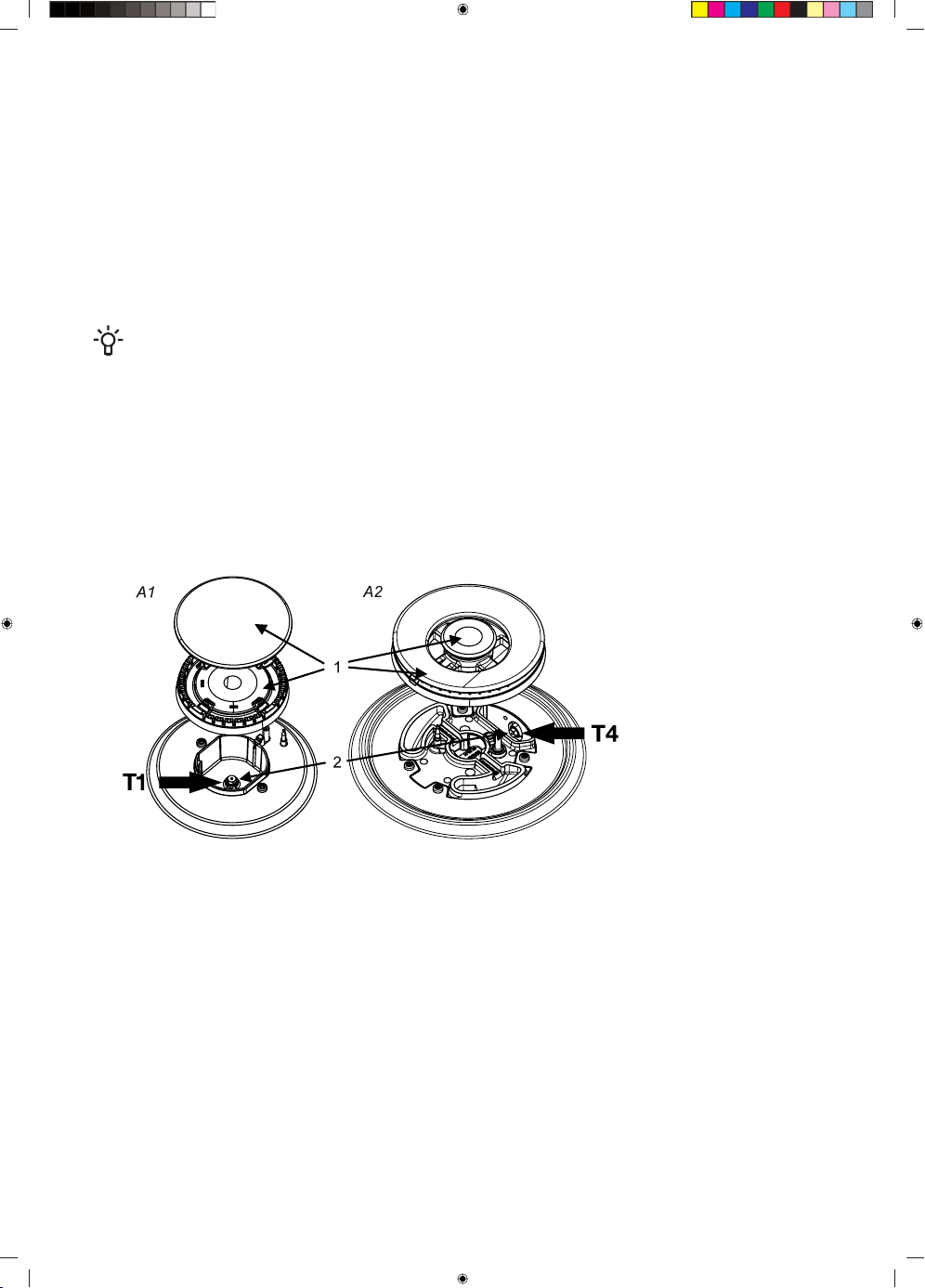
1. Remove pan supports, burner heads, crowns and covers (see pictures A1 and A2).
Pull off the control knobs vertically.
2. Use the socket (T1) or open-end spanner (T4) to remove the old nozzles and place the new nozzles
inside the burner cups (see pictures A1 and A2).
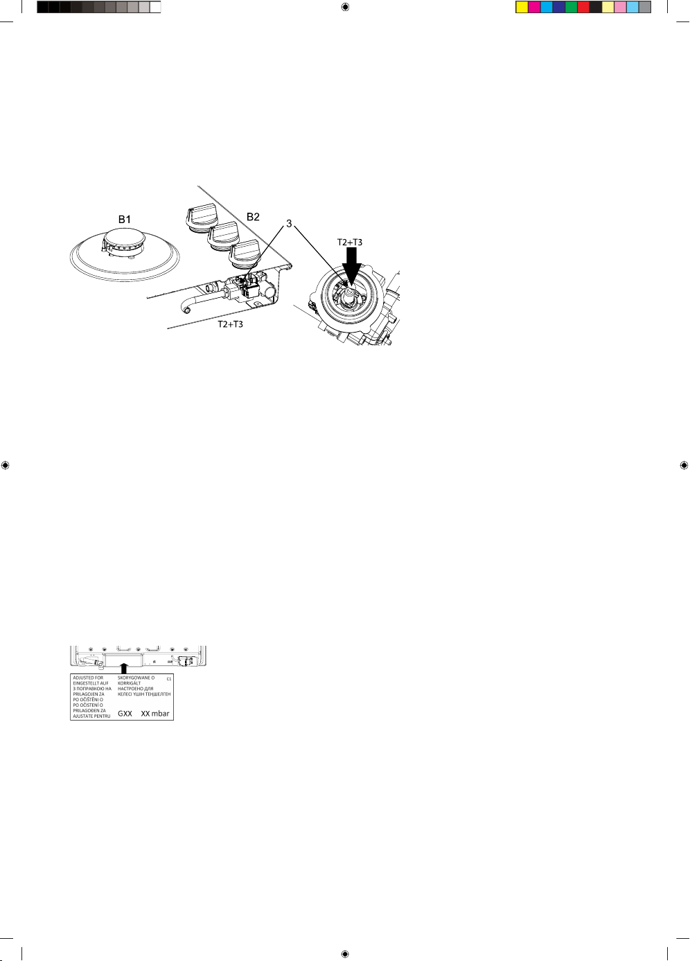
Converting by-pass screws
Depending on the gas type to which the appliances will be converted, there are two ways to adjust
the by-pass screws.
Please check the conversion table in the column “Modification” if the by-pass screws have to be
screwed completely in (see action 3A), replaced by a different by-pass screw (see action 3B) or adjusted
(see action 3C).
The values are also indicated on the top of the by-pass screws. The by-pass screws can be reached
from the top of the hob when the knobs are removed (B2).
3A. Screw the by-pass screws (3) of all gas taps completely in by using the flat-blade screwdriver
(T2).
25
3B. Remove the by-pass screws by using the flat-blade screwdriver (T2) and the nose pliers (T3).
Place the new by-pass screws with the nose pliers and screw the by-pass screws of all gas taps in,
by using the flat-blade screwdriver.
3C. Adjust the by-pass screws (3) of all gas taps by using the flat-blade screwdriver (T2) until a stable
flame is established with a minimal gas flow. Please check if the flame is stable in the cold and hot
condition of the burner.
Check for gas tightness and operation
When the appliance is connected to the gas supply, use leak test spray to check the gas tightness.
1. Seal the injector.
2. Open the gas tap. Attention: press and open tap to override the thermo-electric safety device
and keep it pressed down.
3. Spray leak test spray over all gas connections and check for gas tightness.
4. Repeat for every burner.
Start up
1. Reinstall the knobs, burner parts and pan supports.
2. Check if the appliance is connected to the correct gas type and pressure.
3. Open the main gas valve.
4. Insert the plug into the power socket.
Checking operation
1. Ignite the burners.
2. Check whether the flame profile is normal, uniform and stable for the
complete ratio:
3. • Check if the flame does not smother in simmer rate;
• Check if the flames are not ‘blowing off’ at maximum rate;
• No long, yellow flames should be visible during operation.
4. Paste the data label with the modified gas specifications and setting
over the current data label with old specification (at the underside of
the appliances nearby the gas connection).
26
Environmental considerations
Disposal of the appliance and packaging
Sustainable materials have been used during the manufacture of this appliance.
The appliance packaging is recyclable. The following may have been used:
• cardboard;
• paper;
• polyethylene film (PE);
• CFC-free polystyrene (PS-rigid foam);
• polypropylene tape (PP).
Dispose of these materials in a responsible manner and in accordance with government regulations.
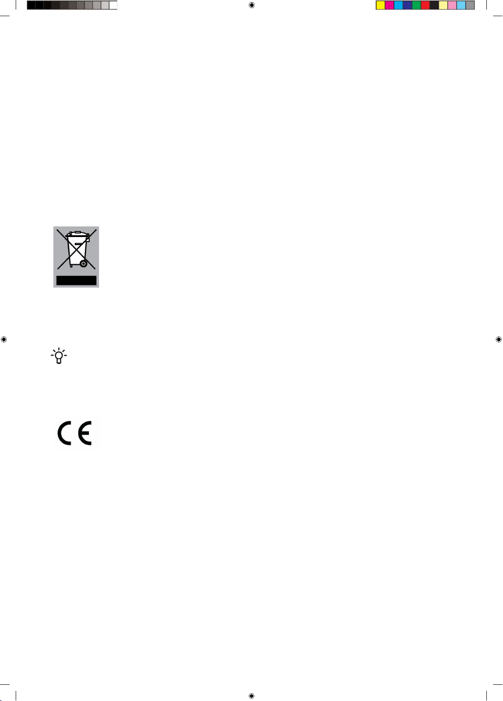
To designate the requirement for separate collection of household electrical
appliances, the symbol of a crossed-out dustbin is applied to the product.
This means that at the end of its working life, the product must not be
disposed of as urban waste. It must be taken to a special local authority
differentiated waste collection centre or to a dealer providing this service.
Disposing of a household appliance such as this hob separately avoids
possible negative consequences for the environment and health and en-
ables the constituent materials to be recovered, resulting in significant
savings in energy and resources.
NOTE!
Please note! Do not throw a broken ceramic glass plate in the glass recycling bin but take
this to the Municipality's waste recycling centre.
Declaration of conformity
We hereby declare that our products satisfy the applicable European directives, orders and regu-
lations, as well as the requirements stated in the referenced standards.
27
843260-a1