INSTRUCTION,
USE & CARE MANUAL
UC-C190SS-30 | UC-C395SS-30 | UC-C395SS_36
READ
A
AND
FOR
SE
DOMESTIC
THESE
COOKING
INSTRUCTIONS
ON
A
INSLLER: Leave this manual with the homeowner.
HOMEOWNER:
Use and Care information on Page
RNING
SUIBLE FOR USE IN HOUSEHOLD COOKING
AREA.
TO REDUCE THE RISK OF FIRE, ELECTRICAL
SHOCK, OR INJURY TO PERSONS, OBSEE
THE FOLLOWING:
1. Use this unit only in the manner intended by the man
ufacturer. If you have the questions, contact the man
ufacturer at the email address or telephone number
listed in the warranty.
2. Before servicing or cleaning unit, switching power o
at seice panel and lock service panel to prevent
power from being switched on accidentally. When the
service disconnecting means cannot be locked, se
curely fasten a prominent warning device, such as a
tag, to the seice panel.
3. Installation work and electrical wiring must be done by
a qualified personnel in accordance with all applica
ble codes and standards, including fire-rated con
struction codes and standards.
4. Suicient air is needed for proper combustion and
exhausting of gases through the flue (chimney) of fuel
burning equipment to prevent back-draing. Follow
the heating equipment manufacturer's guidelines and
safety standards such as those published by the Na
tional Fire Protection Association (NFPA), and the
American Society for Heating, Refrigeration and Air
Conditioning Engineers (ASHRAE), and the local
code authorities.
5. When cutting or drilling into wall or ceiling, do not
damage electrical wiring and other hidden utilities.
6. Ducted fans must always be vented to the outdoors.
7. Do not use this unit with any solid-state speed control
device.
8. To reduce the risk of fire, use only steel ductwork.
9. This unit must be grounded.
TO REDUCE THE RISK OF A RANGE TOP
GREASE FIRE:
A. Never leave suace units unattended at high set
tings. Boilovers cause smoking and greasy spillove
that may ignite. Heat oils slowly on low or medium
settings.
B. Always turn hood ON when cooking at high heat or
when cooking flaming foods.
C. Clean ventilating fans frequently. Grease should not
be allowed to accumulate on fan or filter.
D. Use proper pan size. Always use cookware appropri
ate for the size of the suace element.
RNING
TO REDUCE THE RISK OF INJU TO PERSONS IN
THE EVENT OF A RANGE TOP GREASE FIRE, OB
SERVE THE FOLLOWING*:
1. SMOTHER FLAMES with a close-fitting lid, cookie
sheet or metal tray, then turn o the burner. BE
CAREFUL TO PREVENT BURNS. IF THE
FLAMES DO NOT GO OUT IMMEDIELY, EVAC
UATE AND CALL THE FIRE DERTMENT.
2. NEVER PICK UP A FLAMING N - u may be
burned.
3. DO NOT USE ER, including wet dishcloths or
towels - This could cause a violent steam explo
sion.
4. Use an extinguisher ONLY if:
A. u own a Class ABC extinguisher and you
know how to operate it.
B. The fire is small and contained in the area where
it staed.
C. The fire department has been called.
D. You can fight the fire with your back to an exit.
•Based on "Kitchen Fire Safety Tips" published by NF.
CAUTION
1. For general ventilating use only. Do not use to ex
haust hazardous or explosive materials and vapors.
2.
3.
To avoid motor bearing damage and noisy and/or
unbalanced impellers, keep drywall spray, con
struction dust, etc. o power unit.
For the best capture of cooking impurities, your
range hood should be mounted so that the top of
the hood is 27"-30" above the cooking surface. The
minimum hood distance above electric cooktop
must not be less than 27" and 29" from gas cook
top; any installation less than 27" may cause over
heat and cause damage to the range hood,
Hauslane does not warrant this improper instal
lation.
4. Two installers are recommended because of the
larger size and weight of this hood.
5. To reduce the risk of fire and to properly exhaust
air, be sure to duct air outside - Do not exhaust air
into spaces within walls and ceiling or into attics,
crawl space or garages.
6. Because of the high exhausting capacity of this
hood, you should make sure enough air is entering
the house to replace exhausted air by opening a
window close to or in the kitchen.
7. Use with approved cord-connection kit only.
8. Please read specification label in product for fuher
information and requirements.
Page:2
INSTALL DUCTWORK
VENTING REQUIREMENTS
Determine which venting method is best r your
application. Ductwork can extend either through
the wall or the roof.
A straight, sho duct run will allow the hood to per
form most eiciently. Long duct runs, elbows, and
transitions will reduce the peormance of the hood.
Use as few of them as possible. Larger ducting
may be required r best peormance with longer
duct runs. The length of the ducork and the num
ber of elbows should be kept to a minimum to pro
vide eicient peormance.
The size of the ducork should be unirm. Do not
install two elbows together. Use 2" duct tape to
seal all joints in the ductwork system.
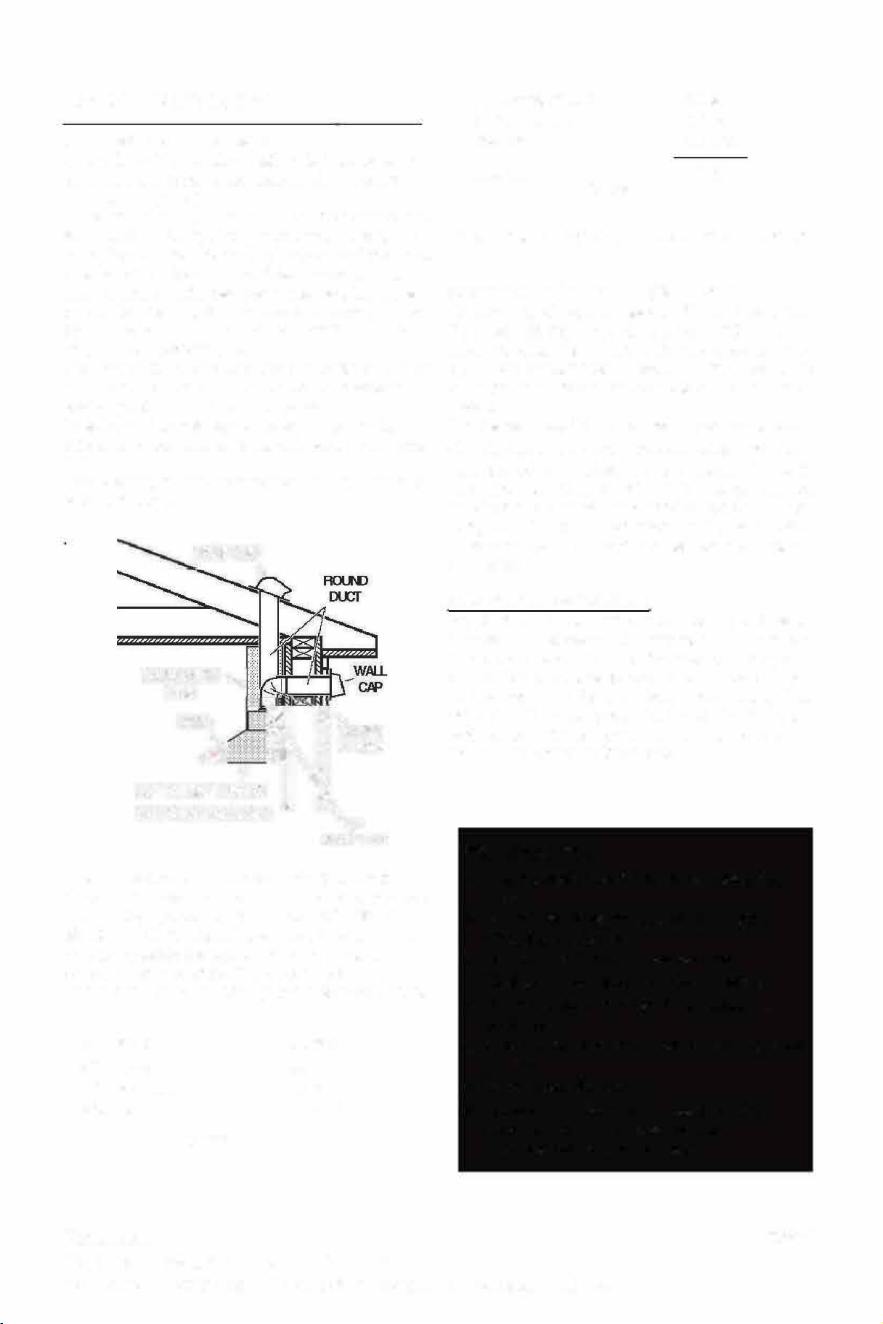
Install a roof or wall cap. Connect round metal
ducork to cap and work back towards hood loca
tion.
Use caulking to seal exterior wall or floor opening
around the cap.
ROOF C
CA
\
26"T:�,b,,lf =
COOKING SURFACE I �
6"
ADAPTER
Flexible ductwork is not recommended. Flexible
ducork creates back pressure and air turbulence
that greatly reduces peormance. USE ON
MEL DUCTWORK. Make sure there is proper
clearance within the wall or floor r exhaust duct
bere making cutouts. Do not cut a joist or stud
unless absolutely necessary. If a joist or stud must
45
°
Elbow
90
°
Elbow
90
°
Flat Elbow
Wall Cap
FIGURE2
3.0 feet
5.0 feet
12.0 feet
0.0 feet
9 feet straight duct
2 - 90
°
Elbows
Wall cap
Total feet
FIGURE 3
9.0 feet
10.0 feet
0.0 feet
19.0 feet
be cut, then a suppoing frame must be construct
ed.
CALCULATE THE DUCT RUN LENGTH
The duct run should not exceed 35 equivalent feet
if ducted with the required minimum of 6" round
duct. Calculate the length of the ductwork by add
ing the equivalent feet in FIGURE 2 r each piece
of duct in the system. An example shown in FIG
URE 3.
For the best results, do not use more than three
90
°
elbows in a system. Make sure that there is a
minimum of 24" of straight duct beeen elbows if
more than one is used. DO NOT install o elbows
together. If you must elbow right away, do it as far
away from the hood's exhaust opening as possible.
Distances over 30" are at the installer and users
discretion.
Cold Weather Installations
An additional back dra damper should be installed
to minimize backward cold air flow and a nonmetal
lic thermal break should be installed to minimize
conduction of outside temperatures as pa of the
vent system. The damper should be on the cold air
side of the thermal break. The break should be as
close as possible to where the vent system enters
the heated poion of the house.
RNING
• Venting system MUST terminate outside the
home.
• DO NOT terminate the ductwork in an attic or
other enclosed space.
• DO NOT use 4" laundry-type wall caps.
• Flexible-type ductwork is not recommended.
• DO NOT obstruct the flow of combustion and
ventilation air.
• Failure to follow venting requirements may result
in a fire.
• Indoor installation ONLY.
e Contact SUMAKI to troubleshoot range
hood. DO NOT try to repair yourself,
otherwise warranty will be voided.
Page:3
Hauslane
267 Wattis Way, San Francisco, CA 94124
Tel: 1-800-929-0168 E-mail: [email protected]
Hauslane
267 Wattis Way, San Francisco, CA 94124
READ
A
AND
FOR
SE
DOMESTIC
THESE
COOKING
INSTRUCTIONS
ON
A
INSLLER: Leave this manual with the homeowner.
HOMEOWNER:
Use and Care information on Page
RNING
SUIBLE FOR USE IN HOUSEHOLD COOKING
AREA.
TO REDUCE THE RISK OF FIRE, ELECTRICAL
SHOCK, OR INJURY TO PERSONS, OBSEE
THE FOLLOWING:
1. Use this unit only in the manner intended by the man
ufacturer. If you have the questions, contact the man
ufacturer at the email address or telephone number
listed in the warranty.
2. Before servicing or cleaning unit, switching power o
at seice panel and lock service panel to prevent
power from being switched on accidentally. When the
service disconnecting means cannot be locked, se
curely fasten a prominent warning device, such as a
tag, to the seice panel.
3. Installation work and electrical wiring must be done by
a qualified personnel in accordance with all applica
ble codes and standards, including fire-rated con
struction codes and standards.
4. Suicient air is needed for proper combustion and
exhausting of gases through the flue (chimney) of fuel
burning equipment to prevent back-draing. Follow
the heating equipment manufacturer's guidelines and
safety standards such as those published by the Na
tional Fire Protection Association (NFPA), and the
American Society for Heating, Refrigeration and Air
Conditioning Engineers (ASHRAE), and the local
code authorities.
5. When cutting or drilling into wall or ceiling, do not
damage electrical wiring and other hidden utilities.
6. Ducted fans must always be vented to the outdoors.
7. Do not use this unit with any solid-state speed control
device.
8. To reduce the risk of fire, use only steel ductwork.
9. This unit must be grounded.
TO REDUCE THE RISK OF A RANGE TOP
GREASE FIRE:
A. Never leave suace units unattended at high set
tings. Boilovers cause smoking and greasy spillove
that may ignite. Heat oils slowly on low or medium
settings.
B. Always turn hood ON when cooking at high heat or
when cooking flaming foods.
C. Clean ventilating fans frequently. Grease should not
be allowed to accumulate on fan or filter.
D. Use proper pan size. Always use cookware appropri
ate for the size of the suace element.
RNING
TO REDUCE THE RISK OF INJU TO PERSONS IN
THE EVENT OF A RANGE TOP GREASE FIRE, OB
SERVE THE FOLLOWING*:
1. SMOTHER FLAMES with a close-fitting lid, cookie
sheet or metal tray, then turn o the burner. BE
CAREFUL TO PREVENT BURNS. IF THE
FLAMES DO NOT GO OUT IMMEDIELY, EVAC
UATE AND CALL THE FIRE DERTMENT.
2. NEVER PICK UP A FLAMING N - u may be
burned.
3. DO NOT USE ER, including wet dishcloths or
towels - This could cause a violent steam explo
sion.
4. Use an extinguisher ONLY if:
A. u own a Class ABC extinguisher and you
know how to operate it.
B. The fire is small and contained in the area where
it staed.
C. The fire department has been called.
D. You can fight the fire with your back to an exit.
•Based on "Kitchen Fire Safety Tips" published by NF.
CAUTION
1. For general ventilating use only. Do not use to ex
haust hazardous or explosive materials and vapors.
2.
3.
To avoid motor bearing damage and noisy and/or
unbalanced impellers, keep drywall spray, con
struction dust, etc. o power unit.
For the best capture of cooking impurities, your
range hood should be mounted so that the top of
the hood is 27"-30" above the cooking surface. The
minimum hood distance above electric cooktop
must not be less than 27" and 29" from gas cook
top; any installation less than 27" may cause over
heat and cause damage to the range hood,
Hauslane does not warrant this improper instal
lation.
4. Two installers are recommended because of the
larger size and weight of this hood.
5. To reduce the risk of fire and to properly exhaust
air, be sure to duct air outside - Do not exhaust air
into spaces within walls and ceiling or into attics,
crawl space or garages.
6. Because of the high exhausting capacity of this
hood, you should make sure enough air is entering
the house to replace exhausted air by opening a
window close to or in the kitchen.
7. Use with approved cord-connection kit only.
8. Please read specification label in product for fuher
information and requirements.
Page:2
INSTALL DUCTWORK
VENTING REQUIREMENTS
Determine which venting method is best r your
application. Ductwork can extend either through
the wall or the roof.
A straight, sho duct run will allow the hood to per
form most eiciently. Long duct runs, elbows, and
transitions will reduce the peormance of the hood.
Use as few of them as possible. Larger ducting
may be required r best peormance with longer
duct runs. The length of the ducork and the num
ber of elbows should be kept to a minimum to pro
vide eicient peormance.
The size of the ducork should be unirm. Do not
install two elbows together. Use 2" duct tape to
seal all joints in the ductwork system.
Install a roof or wall cap. Connect round metal
ducork to cap and work back towards hood loca
tion.
Use caulking to seal exterior wall or floor opening
around the cap.
ROOF C
CA
\
26"T:�,b,,lf =
COOKING SURFACE I �
6"
ADAPTER
Flexible ductwork is not recommended. Flexible
ducork creates back pressure and air turbulence
that greatly reduces peormance. USE ON
MEL DUCTWORK. Make sure there is proper
clearance within the wall or floor r exhaust duct
bere making cutouts. Do not cut a joist or stud
unless absolutely necessary. If a joist or stud must
45
°
Elbow
90
°
Elbow
90
°
Flat Elbow
Wall Cap
FIGURE2
3.0 feet
5.0 feet
12.0 feet
0.0 feet
9 feet straight duct
2 - 90
°
Elbows
Wall cap
Total feet
FIGURE 3
9.0 feet
10.0 feet
0.0 feet
19.0 feet
be cut, then a suppoing frame must be construct
ed.
CALCULATE THE DUCT RUN LENGTH
The duct run should not exceed 35 equivalent feet
if ducted with the required minimum of 6" round
duct. Calculate the length of the ductwork by add
ing the equivalent feet in FIGURE 2 r each piece
of duct in the system. An example shown in FIG
URE 3.
For the best results, do not use more than three
90
°
elbows in a system. Make sure that there is a
minimum of 24" of straight duct beeen elbows if
more than one is used. DO NOT install o elbows
together. If you must elbow right away, do it as far
away from the hood's exhaust opening as possible.
Distances over 30" are at the installer and users
discretion.
Cold Weather Installations
An additional back dra damper should be installed
to minimize backward cold air flow and a nonmetal
lic thermal break should be installed to minimize
conduction of outside temperatures as pa of the
vent system. The damper should be on the cold air
side of the thermal break. The break should be as
close as possible to where the vent system enters
the heated poion of the house.
RNING
• Venting system MUST terminate outside the
home.
• DO NOT terminate the ductwork in an attic or
other enclosed space.
• DO NOT use 4" laundry-type wall caps.
• Flexible-type ductwork is not recommended.
• DO NOT obstruct the flow of combustion and
ventilation air.
• Failure to follow venting requirements may result
in a fire.
• Indoor installation ONLY.
e Contact SUMAKI to troubleshoot range
hood. DO NOT try to repair yourself,
otherwise warranty will be voided.
Page:3
Hauslane
267 Wattis Way, San Francisco, CA 94124
Tel: 1-800-929-0168 E-mail: info@hauslane.com
Hauslane
267 Wattis Way, San Francisco, CA 94124
Tel: 1-800-929-0168 E-mail: [email protected]

ELECTRICAL REQUIREMENTS
Before installation and usage, read all the in
structions and make sure that the voltage (V)
and the frequency (Hz) indicated on the identi
fication plate (found inside your range hood)
and all the data inside the appliance are exactly
the same as the voltage and frequency in your
home.
Note: The manufacturer declines all responsibility
in the event of failure to observe all the accident
prevention regulations in rce which are neces
sary r normal use and regular operation of the
electric system.
This appliance must be grounded.
This appliance is equipped with a grounding plug cord,
the plug must be plugged into an outlet that is properly
installed and grounded.
Set the electrical power supply within the space covered
by the decorative flues. Position the power socket at a
maximum distance of 30" from where the lead exits from
the hood. Make sure this does not inteace with the
bracket fastening area or with the decorative flue (where
the flue attached to the wall).
Fil the plug into the power socket. Hard wire connection
is not recommended.
RNING
• Electrical ground is required on this range hood.
• If cold water pipe is interrupted by plastic, non
metallic gaskets or other materials, DO NOT
use for grounding.
• DO NOT ground to a gas pipe.
• DO NOT have a fuse in the neutral or grounding
circuit. A fuse in the neutral or grounding circuit
could result in electrical shock.
• Check with a qualified electrician if you are in
doubt as to whether the range hood is properly
grounded.
• DO NOT use this appliance with any solid state
fan speed control device.
• DO NOT use an extension cord. If the power
supply cord is too short, hire a qualified electri
cian to install an outlet near the appliance.
A 120 volt, 6
0 Hz AC-only electrical supply is re
quired on a separate 15 amp fused circuit. A time
delay fuse or circuit breaker is recommended. The
fuse must be sized per local codes in accordance
with the electrical rating of this unit as specified on
the serial/rating plate located inside the unit near
the field wiring compartment. THIS UNIT MUST BE
CONNECTED WITH COPPER WIRE ONL Wire
sizes must conform to the requirements of the Na
tional Electrical Code, ANSI/NFPA 70 - latest edi-
lion, and all local codes and ordinances. Wire size
and connections must conrm with the rating of
the appliance. Copies of the standard listed above
may be obtained from:
National Fire Protection Association
Batterymarch Park
Quincy, Massachusetts 02269
For residential use only.
This appliance should be connected directly to the
fused disconnect( or circuit breaker) through flexi
ble, armored or nonmetallic sheathes copper cable.
Allow some slack in the cable so the appliance can
be removed if servicing is ever necessary. A UL
Listed, 1/2" conduit connector must be provided at
each and of the power supply cable (at the appli
ance and at the junction box)
When making the electrical connection, cut a 1-1/4"
hole in the wall. A hole cut through wood must be
sanded until smooth. A hole through metal must
have a grommet.
WARNING -TO REDUCE THE RISK OF FIRE OR
ELECTRIC SHOCK, do not use this fan with any
solid-state speed control device.
WARNING -TO REDUCE THE RISK OF FIRE,
ELECTRICAL SHOCK, OR INJURY TO PER
SONS, OBSERVE THE FOLLOWING: Use this
unit only in the manner intended by the manu
facturer. If you have any questions, contact the
manufacturer ..
Before servicing or cleaning unit, switch power o
at service panel and lock the service disconnecting
means to prevent power from being switched on
accidentally. When the service disconnecting
means cannot be locked, securely fasten a promi
nent warning device, such as a tag, to the service
panel.
When cutting or drilling into wall or ceiling, do not
damage electrical wiring and other hidden utilities.
CAUTION: For General Ventilating Use Only. DO
NOT use to exhaust hazardous or explosive
materials and vapors.
WARNING - TO REDUCE THE RISK OF FIRE,
ELECTRICAL SHOCK, OR INJURY TO PER
SONS, OBSERVE THE FOLLOWING: Installa
tion work and electrical wiring must be done by
qualified person(s) in accordance with all appli
cable codes and standards, including fire-rating
construction.
Page:4
PLAN THE INSTALLION
LOCATION PRERATION
The hood should be mounted to the boom of a standard
1.
wall cabinet. If the hood must be mounted directly to the
wall, secure the hood to wall studs.
Use the dimensional drawings below to lay out
the range hood's mounng holes, wiring access
and ductwork by marking the cabinet boom and
drywall where applicable.
2. Make cutouts r wiring and ductwork.
The hood is connected to a 110-120V AC lighng circuit
(15 amp) in the circuit breaker or fuse box.
3. Install the ductwork so that it is ush to the range
hood's mounng surface.
• Ductwork can be installed vercally or horizontally.
• Duct runs should be as short as possible.
• Avoid the use of elbows.
4. Run two-conductor wire (with ground) from a
power source to the hood locaon. Bring approxi
mately 1/2" of wiring through wiring hole.
• Use duct tape at all joints.
• Do not use duct smaller than the discharge on the
hood.
5. Drill four 3/32" diameter pilot holes at points
where mounng holes are marked in cabinet
boom.
6. Insert (4) mounng screws, leaving approximately
1/4" of thread exposed.
NOTE: If the boom of the cabinet is recessed,
attached wood strips (not included), as shown
beside, in order to properly install the range
under the cabinet. The wood strips must be as
thick as recess.
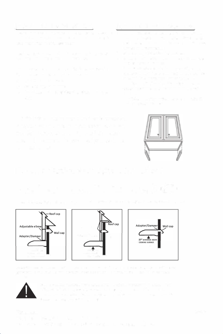
Ducting Options (adapters included)
Option 1 � Option 2� Option 3 �
6" round duct Vertical Discharge
3-1/4" x 10" duct Vertical Discharge 3-1/4" x 10" duct Horizontal Discharge
27" MINIMt ABOVE
COOKING SURFACE
(29" FOR GAS RANGE)
Adjustable elbow
Adapter/Damper
"
27" MINIM M ABOVE
COOKING SURFACE
(29
H
FOR GAS RANGE)
'
Wall cap
(29
H
FORGASRANGE)
Note: We recommend to install the hood at a minimum 27" from an electric range and at 29" from a
gas range. For optimal performance, the hood should not be installed more than 32
"
from cooking
surface.
Please read the manual before installation. Identifies an instruction which, if not
followed, might cause serious personal injuries including possibility of death.
Denotes an instruction which, if not followed, may severely damage the unit and/or
its components; warranty will be void.
Page: 5
Hauslane
267 Wattis Way, San Francisco, CA 94124
Hauslane
267 Wattis Way, San Francisco, CA 94124
Tel: 1-800-929-0168 E-mail: [email protected]
ELECTRICAL REQUIREMENTS
Before installation and usage, read all the in
structions and make sure that the voltage (V)
and the frequency (Hz) indicated on the identi
fication plate (found inside your range hood)
and all the data inside the appliance are exactly
the same as the voltage and frequency in your
home.
Note: The manufacturer declines all responsibility
in the event of failure to observe all the accident
prevention regulations in rce which are neces
sary r normal use and regular operation of the
electric system.
This appliance must be grounded.
This appliance is equipped with a grounding plug cord,
the plug must be plugged into an outlet that is properly
installed and grounded.
Set the electrical power supply within the space covered
by the decorative flues. Position the power socket at a
maximum distance of 30" from where the lead exits from
the hood. Make sure this does not inteace with the
bracket fastening area or with the decorative flue (where
the flue attached to the wall).
Fil the plug into the power socket. Hard wire connection
is not recommended.
RNING
• Electrical ground is required on this range hood.
• If cold water pipe is interrupted by plastic, non
metallic gaskets or other materials, DO NOT
use for grounding.
• DO NOT ground to a gas pipe.
• DO NOT have a fuse in the neutral or grounding
circuit. A fuse in the neutral or grounding circuit
could result in electrical shock.
• Check with a qualified electrician if you are in
doubt as to whether the range hood is properly
grounded.
• DO NOT use this appliance with any solid state
fan speed control device.
• DO NOT use an extension cord. If the power
supply cord is too short, hire a qualified electri
cian to install an outlet near the appliance.
A 120 volt, 6
0 Hz AC-only electrical supply is re
quired on a separate 15 amp fused circuit. A time
delay fuse or circuit breaker is recommended. The
fuse must be sized per local codes in accordance
with the electrical rating of this unit as specified on
the serial/rating plate located inside the unit near
the field wiring compartment. THIS UNIT MUST BE
CONNECTED WITH COPPER WIRE ONL Wire
sizes must conform to the requirements of the Na
tional Electrical Code, ANSI/NFPA 70 - latest edi-
lion, and all local codes and ordinances. Wire size
and connections must conrm with the rating of
the appliance. Copies of the standard listed above
may be obtained from:
National Fire Protection Association
Batterymarch Park
Quincy, Massachusetts 02269
For residential use only.
This appliance should be connected directly to the
fused disconnect( or circuit breaker) through flexi
ble, armored or nonmetallic sheathes copper cable.
Allow some slack in the cable so the appliance can
be removed if servicing is ever necessary. A UL
Listed, 1/2" conduit connector must be provided at
each and of the power supply cable (at the appli
ance and at the junction box)
When making the electrical connection, cut a 1-1/4"
hole in the wall. A hole cut through wood must be
sanded until smooth. A hole through metal must
have a grommet.
WARNING -TO REDUCE THE RISK OF FIRE OR
ELECTRIC SHOCK, do not use this fan with any
solid-state speed control device.
WARNING -TO REDUCE THE RISK OF FIRE,
ELECTRICAL SHOCK, OR INJURY TO PER
SONS, OBSERVE THE FOLLOWING: Use this
unit only in the manner intended by the manu
facturer. If you have any questions, contact the
manufacturer ..
Before servicing or cleaning unit, switch power o
at service panel and lock the service disconnecting
means to prevent power from being switched on
accidentally. When the service disconnecting
means cannot be locked, securely fasten a promi
nent warning device, such as a tag, to the service
panel.
When cutting or drilling into wall or ceiling, do not
damage electrical wiring and other hidden utilities.
CAUTION: For General Ventilating Use Only. DO
NOT use to exhaust hazardous or explosive
materials and vapors.
WARNING - TO REDUCE THE RISK OF FIRE,
ELECTRICAL SHOCK, OR INJURY TO PER
SONS, OBSERVE THE FOLLOWING: Installa
tion work and electrical wiring must be done by
qualified person(s) in accordance with all appli
cable codes and standards, including fire-rating
construction.
Page:4
PLAN THE INSTALLION
LOCATION PRERATION
The hood should be mounted to the boom of a standard
1.
wall cabinet. If the hood must be mounted directly to the
wall, secure the hood to wall studs.
Use the dimensional drawings below to lay out
the range hood's mounng holes, wiring access
and ductwork by marking the cabinet boom and
drywall where applicable.
2. Make cutouts r wiring and ductwork.
The hood is connected to a 110-120V AC lighng circuit
(15 amp) in the circuit breaker or fuse box.
3. Install the ductwork so that it is ush to the range
hood's mounng surface.
• Ductwork can be installed vercally or horizontally.
• Duct runs should be as short as possible.
• Avoid the use of elbows.
4. Run two-conductor wire (with ground) from a
power source to the hood locaon. Bring approxi
mately 1/2" of wiring through wiring hole.
• Use duct tape at all joints.
• Do not use duct smaller than the discharge on the
hood.
5. Drill four 3/32" diameter pilot holes at points
where mounng holes are marked in cabinet
boom.
6. Insert (4) mounng screws, leaving approximately
1/4" of thread exposed.
NOTE: If the boom of the cabinet is recessed,
attached wood strips (not included), as shown
beside, in order to properly install the range
under the cabinet. The wood strips must be as
thick as recess.
Ducting Options (adapters included)
Option 1 � Option 2� Option 3 �
6" round duct Vertical Discharge
3-1/4" x 10" duct Vertical Discharge 3-1/4" x 10" duct Horizontal Discharge
27" MINIMt ABOVE
COOKING SURFACE
(29" FOR GAS RANGE)
Adjustable elbow
Adapter/Damper
"
27" MINIM M ABOVE
COOKING SURFACE
(29
H
FOR GAS RANGE)
'
Wall cap
(29
H
FORGASRANGE)
Note: We recommend to install the hood at a minimum 27" from an electric range and at 29" from a
gas range. For optimal performance, the hood should not be installed more than 32
"
from cooking
surface.
Please read the manual before installation. Identifies an instruction which, if not
followed, might cause serious personal injuries including possibility of death.
Denotes an instruction which, if not followed, may severely damage the unit and/or
its components; warranty will be void.
Page: 5
Hauslane
267 Wattis Way, San Francisco, CA 94124
Tel: 1-800-929-0168 E-mail: [email protected]
Hauslane
267 Wattis Way, San Francisco, CA 94124
Tel: 1-800-929-0168 E-mail: info@hauslane.com
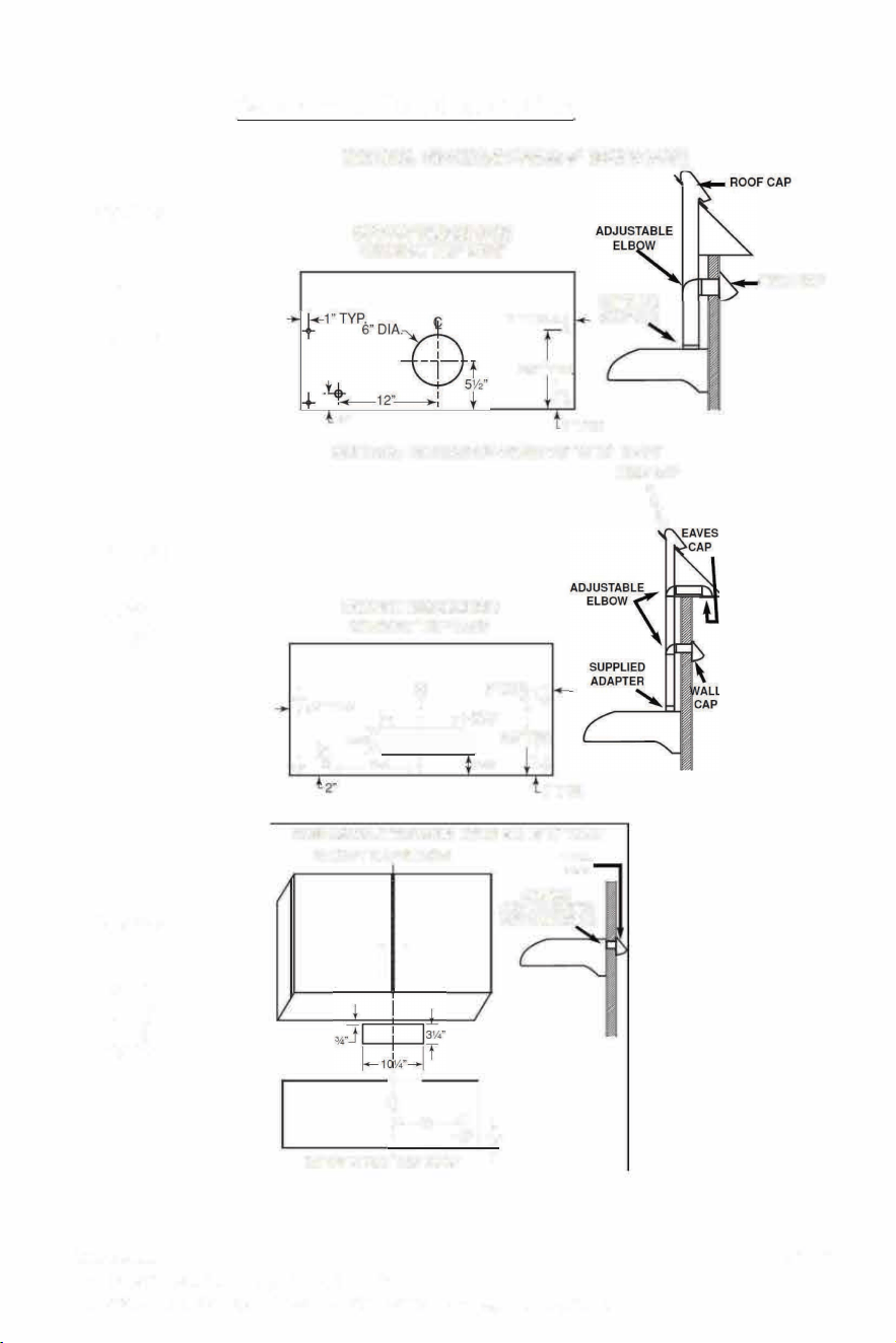
Opon
1
Opon
2
Opon
3
Select ur Ducting Option
VERTICAL DISCHARGE USING 6" ROUND DUCT
CUTOUT DIMENSIONS
CABINET TOP VIEW
1" TYP.
i
9½"TYP
4
SUPPLIED
ADAPTER
2"
l"TYP.
VERTICAL DISCHARGE USING 3 ¼" X 10" DUCT
ROOF CAP
CUTOUT DIMENSIONS
CABINET TOP VIEW
+
�
1"TYP.
�
.-l"TYP.
1
r
�I ·�•11
O
¼
"
3V,I
I ! _
gv, TYP.
+ ,12"�:
2¼"
4
1"TYP.
HORIZONL DISCHARGE USING 3 ¼" X 1 O" DUCT
CUTOUT DIMENSIONS
I I
�,,-��½
CABINET BOTTOM VIEW T
WALL
CAP
SUPPLIED
ADAPTER/DAMPER
(INSIDE THE HOOD)
\
WALL CAP
Page:6
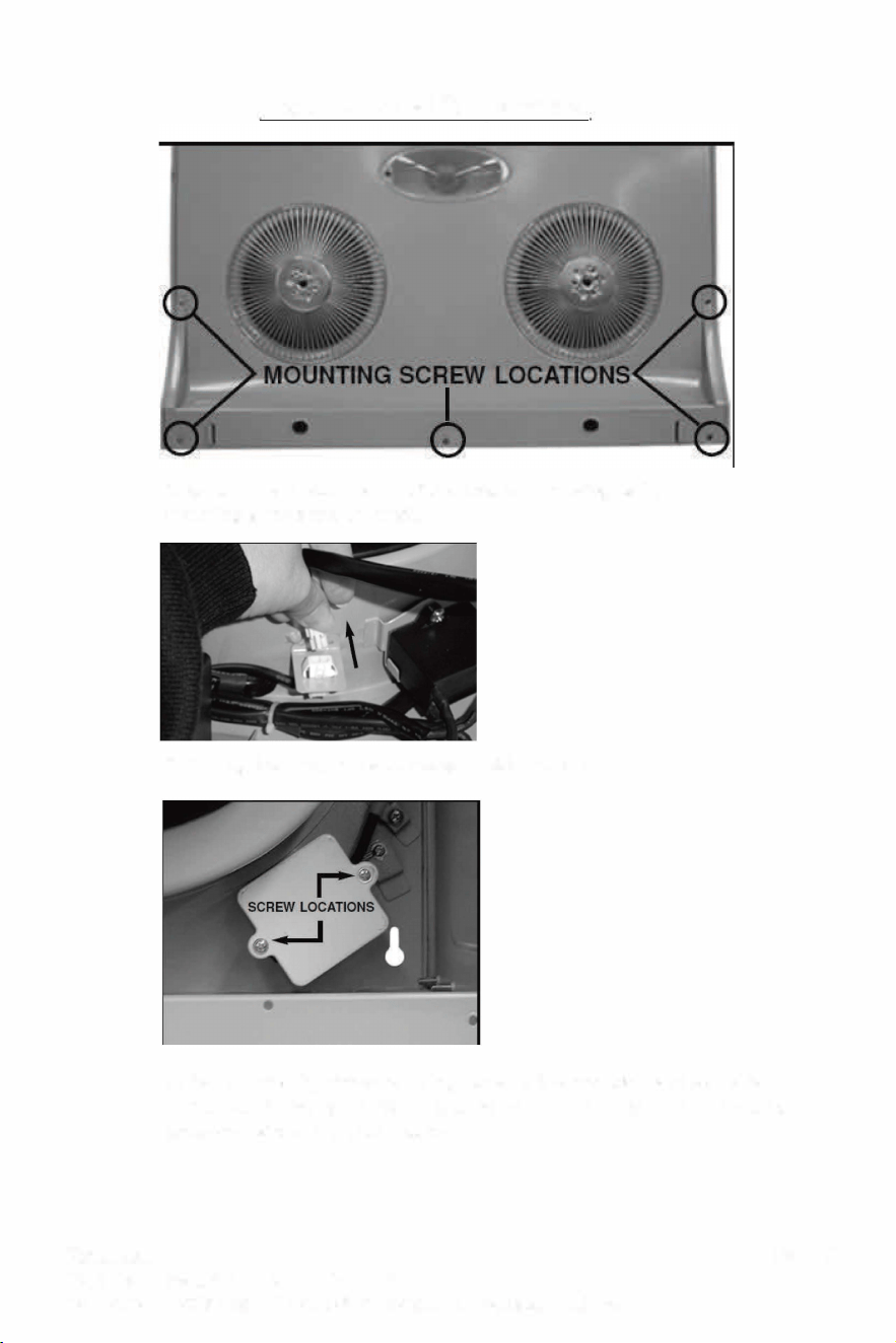
Step 1- Hood Preparation
1. Remove the boom panel of the hood by removing its (5)
mounting screws and set aside.
2. Unplug the small white connector inside the hood.
3. Remove the (2) screws retaining the electrical box cover and set aside.
Punch out the wiring knock-out located on the TOP of the unit and install an
approved wire clamp (not included).
Page: 7
Hauslane
267 Wattis Way, San
Francisco, CA 94124
Tel: 1-800-929-0168 E-mail: info@hauslane.com
Hauslane
267 Wattis Way, San Francisco, CA 94124
Tel: 1-800-929-0168 E-mail: info@hauslane.com
Opon
1
Opon
2
Opon
3
Select ur Ducting Option
VERTICAL DISCHARGE USING 6" ROUND DUCT
CUTOUT DIMENSIONS
CABINET TOP VIEW
1" TYP.
i
9½"TYP
4
SUPPLIED
ADAPTER
2"
l"TYP.
VERTICAL DISCHARGE USING 3 ¼" X 10" DUCT
ROOF CAP
CUTOUT DIMENSIONS
CABINET TOP VIEW
+
�
1"TYP.
�
.-l"TYP.
1
r
�I ·�•11
O
¼
"
3V,I
I ! _
gv, TYP.
+ ,12"�:
2¼"
4
1"TYP.
HORIZONL DISCHARGE USING 3 ¼" X 1 O" DUCT
CUTOUT DIMENSIONS
I I
�,,-��½
CABINET BOTTOM VIEW T
WALL
CAP
SUPPLIED
ADAPTER/DAMPER
(INSIDE THE HOOD)
\
WALL CAP
Page:6
Step 1- Hood Preparation
1. Remove the boom panel of the hood by removing its (5)
mounting screws and set aside.
2. Unplug the small white connector inside the hood.
3. Remove the (2) screws retaining the electrical box cover and set aside.
Punch out the wiring knock-out located on the TOP of the unit and install an
approved wire clamp (not included).
Page: 7
Hauslane
267 Wattis Way, San
Francisco, CA 94124
Tel: 1-800-929-0168 E-mail: info@hauslane.com
Hauslane
267 Wattis Way, San Francisco, CA 94124
Tel: 1-800-929-0168 E-mail: info@hauslane.com
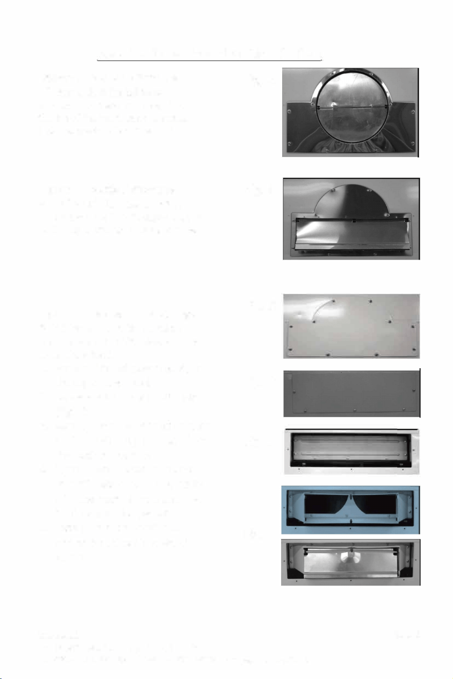
Step 2 - Select Your Ducting Option
Opon 1-vercal discharge
6" round duct installaon
6" round duct installaon (Fig. A) on
the top of the hood, using 10 screws
(adapter pre-installed at factory)
Opon 2-vercal discharge
3-1/4" x 10" duct installaon
Mount the 3-1
/
4" x 10" adapter (Fig. B)
on the top of the hood, using 10 screws
Opon 3- horizontal discharge
3-1/4" x 10" duct installaon
Mount the 3-1
/
4" x 10" adapter on the
BACK of the hood.
1. Remove the adapter
{
Fig. A) on
the top of the hood.
2. Replace with the shuto plate
{
Fig.
C
)
3. Remove and discard rectangular
shuto plate (Fig. D) located on
the back of the hood.
4. Remove and discard the small
shuto plate (Fig. E) located IN
SIDE the back ofthe hood. DO
NOT remove the gasket!
5. Install the adapter with 10
screws previous removed at
step 4.
Fig. A
Fig. B
Fig. C
Fig. D
Fig. E
I
Fig. F
I
Page:8
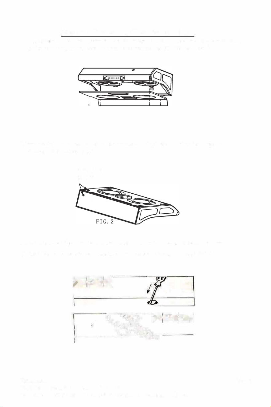
Step 3 - Preparing The Range Hood
1. Unpacking and check the contents. st the range hood to check all the funcon is normal
before you installation. Remove wiring cover screw and lift off cover (Fig.1)
2. Remove the top or the rear electrical knockout, bring power cord to the range hood
(through the cabinet) (Fig.2)
KEYHOLE
SLOTS
3. Insert a screwdriver into the knockout slot and bend the knockout back and forth
(FIG.3-1).You may have to use pliers to pull the loosened knockout free (FIG.3-2)
Mi¼IM
---�
Page:9
Hauslane
267 Wattis Way, San
Francisco, CA 94124
Tel: 1-800-929-0168 E-mail: info@hauslane.com
Hauslane
267 Wattis Way, San Francisco, CA 94124
Tel: 1-800-929-0168 E-mail: info@hauslane.com
Step 2 - Select Your Ducting Option
Opon 1-vercal discharge
6" round duct installaon
6" round duct installaon (Fig. A) on
the top of the hood, using 10 screws
(adapter pre-installed at factory)
Opon 2-vercal discharge
3-1/4" x 10" duct installaon
Mount the 3-1
/
4" x 10" adapter (Fig. B)
on the top of the hood, using 10 screws
Opon 3- horizontal discharge
3-1/4" x 10" duct installaon
Mount the 3-1
/
4" x 10" adapter on the
BACK of the hood.
1. Remove the adapter
{
Fig. A) on
the top of the hood.
2. Replace with the shuto plate
{
Fig.
C
)
3. Remove and discard rectangular
shuto plate (Fig. D) located on
the back of the hood.
4. Remove and discard the small
shuto plate (Fig. E) located IN
SIDE the back ofthe hood. DO
NOT remove the gasket!
5. Install the adapter with 10
screws previous removed at
step 4.
Fig. A
Fig. B
Fig. C
Fig. D
Fig. E
I
Fig. F
I
Page:8
Step 3 - Preparing The Range Hood
1. Unpacking and check the contents. st the range hood to check all the funcon is normal
before you installation. Remove wiring cover screw and lift off cover (Fig.1)
2. Remove the top or the rear electrical knockout, bring power cord to the range hood
(through the cabinet) (Fig.2)
KEYHOLE
SLOTS
3. Insert a screwdriver into the knockout slot and bend the knockout back and forth
(FIG.3-1).You may have to use pliers to pull the loosened knockout free (FIG.3-2)
Mi¼IM
---�
Page:9
Hauslane
267 Wattis Way, San
Francisco, CA 94124
Tel: 1-800-929-0168 E-mail: info@hauslane.com
Hauslane
267 Wattis Way, San Francisco, CA 94124
Tel: 1-800-929-0168 E-mail: info@hauslane.com
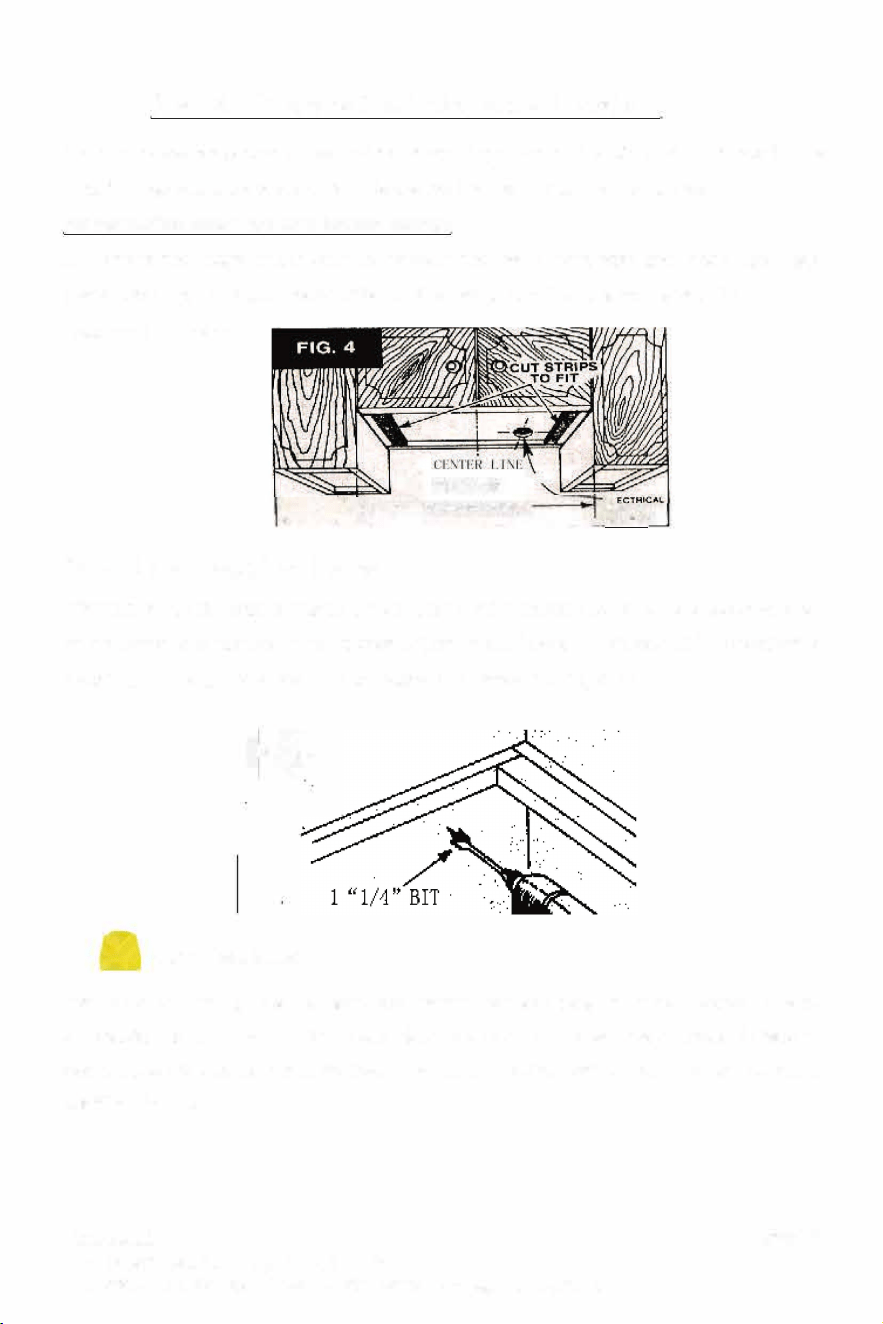
Step 4- Prepare the Installation Location
If you move the range hood to make room for working on the cabinet ,turn off the power for the
electric range at the service entrance .Before moving a gas range, shut off the gas.
For installaon onto a recessed boom cabinet:
a. Measure the space (under cabinet) between the inside front edge and inside back edge
(FIG.4).With a saber saw cut two lx2"wood ller strips (purchased seperately) to ll in the
bottom of the cabinet.
WI II Ol
i •---RANGE HOOD
�1N
, ·-- OPfING
Providing Electrical Power
After turning off the proper 120volt circuit at the service entrance ,d ri 11 out the electrical pow
er line access hole marked on the cabinet boom or wall (use a 1 1/4"wood bit
)
. operate the
electric drill
,
use an extension cord connected to another circuit (FIG.SJ.
'"''
m SAFE RNING
If drilling into the walls, be careful not to cut exisng electrical cables, which would create a hazard.
All electrical connecons must be in accordance with local codes, decrees or naonal electrical
codes. If you are unfamiliar with methods of installing electrical wiring, secure the services with a
qualied electrician.
Page: 10
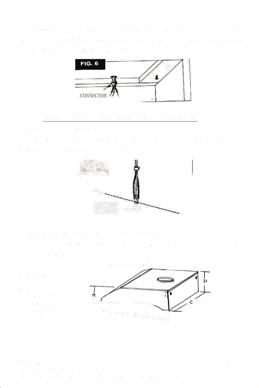
3. Fish the electrical power line through the access hole drilled in the wall or boom of the
cabinet. Aach an appropriate connector (purchased seperately)to the end of the power line for
the type of wiring being installed follow all codes. (FIG.6).
I
Step 5 - Mount the Range Hood to Cabinet
1. Posion the hood in place so that:
The electrical line is routed through the appropriate knockout opening .This step will have to
be accomplished while posioning the hood (FIG.7).
'"''
KNOCKOUT
O·
OPENING -
2. Adjust the hood so the front is flush with the cabinet front.
3. Tighten the hood mounng screws all the way into the cabinet or into the l"x2"wood strips
so the hood is secure.
Dimension:
A) 5-1/2"
B) 22"
C)
U
C
-C190ss-30 -30"
U
C-C395ss-30-30"
U
C-C395ss-36- 36"
D) 7-7/8"
�----
1
Page: 11
Hauslane
267 Wattis Way, San Franci
sco, CA 94124
Hauslane
267 Wattis Way, San Francisco, CA 94124
Tel: 1-800-929-0168 E-mail: [email protected]
Step 4- Prepare the Installation Location
If you move the range hood to make room for working on the cabinet ,turn off the power for the
electric range at the service entrance .Before moving a gas range, shut off the gas.
For installaon onto a recessed boom cabinet:
a. Measure the space (under cabinet) between the inside front edge and inside back edge
(FIG.4).With a saber saw cut two lx2"wood ller strips (purchased seperately) to ll in the
bottom of the cabinet.
WI II Ol
i •---RANGE HOOD
�1N
, ·-- OPfING
Providing Electrical Power
After turning off the proper 120volt circuit at the service entrance ,d ri 11 out the electrical pow
er line access hole marked on the cabinet boom or wall (use a 1 1/4"wood bit
)
. operate the
electric drill
,
use an extension cord connected to another circuit (FIG.SJ.
'"''
m SAFE RNING
If drilling into the walls, be careful not to cut exisng electrical cables, which would create a hazard.
All electrical connecons must be in accordance with local codes, decrees or naonal electrical
codes. If you are unfamiliar with methods of installing electrical wiring, secure the services with a
qualied electrician.
Page: 10
3. Fish the electrical power line through the access hole drilled in the wall or boom of the
cabinet. Aach an appropriate connector (purchased seperately)to the end of the power line for
the type of wiring being installed follow all codes. (FIG.6).
I
Step 5 - Mount the Range Hood to Cabinet
1. Posion the hood in place so that:
The electrical line is routed through the appropriate knockout opening .This step will have to
be accomplished while posioning the hood (FIG.7).
'"''
KNOCKOUT
O·
OPENING -
2. Adjust the hood so the front is flush with the cabinet front.
3. Tighten the hood mounng screws all the way into the cabinet or into the l"x2"wood strips
so the hood is secure.
Dimension:
A) 5-1/2"
B) 22"
C)
U
C
-C190ss-30 -30"
U
C-C395ss-30-30"
U
C-C395ss-36- 36"
D) 7-7/8"
�----
1
Page: 11
Hauslane
267 Wattis Way, San Franci
sco, CA 94124
Tel: 1-800-929-0168 E-mail: [email protected]
Hauslane
267 Wattis Way, San Francisco, CA 94124
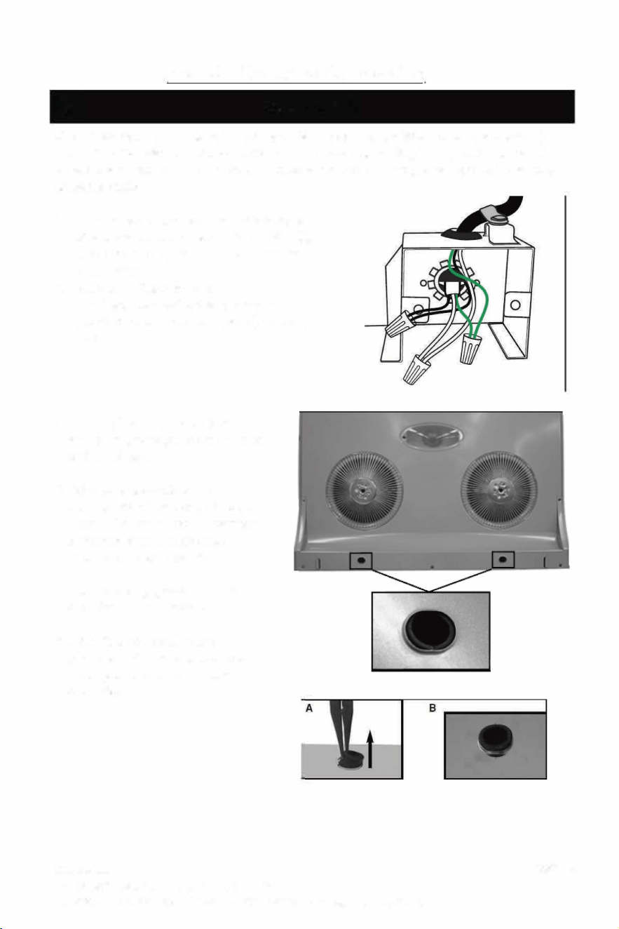
Step 6 - Electrical Connection
� WARNING
Risk of electrical shock. Electrical wiring must be done by qualied personnel in accord
ance with all applicable codes and standards. Before connecng wires, switch power o at
service panel and lock service disconnecon means to prevent power from being switched
on accidentally.
1. Connect cable to range hood wiring using
wire connectors. Connect BLACK to BLACK,
WHITE to WHITE, GREEN or BARE wire to
GREEN wire.
2. Reinstall wiring box cover.
3. Plug back the small white connector
(aached with the boom panel) inside the
hood.
4. Reinstall boom panel. Make
sure both grease guides are aligned
with the holes.
5. Using long nose pliers, pull out
the end of each grease guides (A).
Then, set them in such a way their
slightly protrudes above the
boom panel surface (B).
6. Install the long grease cup at the
end of the hood bottom.
7. Install the two small round
grease guard cups onto the two
metal guard. Push in and turn
clockwise.
Page: 12
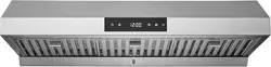
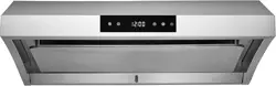
Model: C190 Standard Series
A. Power O Switch
B. Low Speed Switch
C. Middle Speed Switch
D. High Speed Switch
E. Light Switch
r�r r
E D C BA
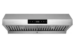
Model:
C
395 Premium Auto-clean Series
A. Auto-Clean Switch- press once will go into the 38 seconds auto-clean mode. It
will starts to spray the degreaser that stored at the water tank and clean up the fans,
then automatically stop in 38 seconds.
B. Low Speed Switch (6 speed step down)
C. High Speed Switch (6 speed step up)
D. Power On/o Switch
E. Light Switch
B
CD E
Install/ Replace of the Light Bulb
Light bulb is included in this package.
F
or future replacement, this is a
110
/
120
V
, 40W A-15 type incandescent lamp (a
v
ailable at most
hardware stores). We highly recommend using a 3.5W LED light bulb.
RNING - If you use a bulb over 40W, it will seriously caused damage to the
hood and the warranty will be voided!
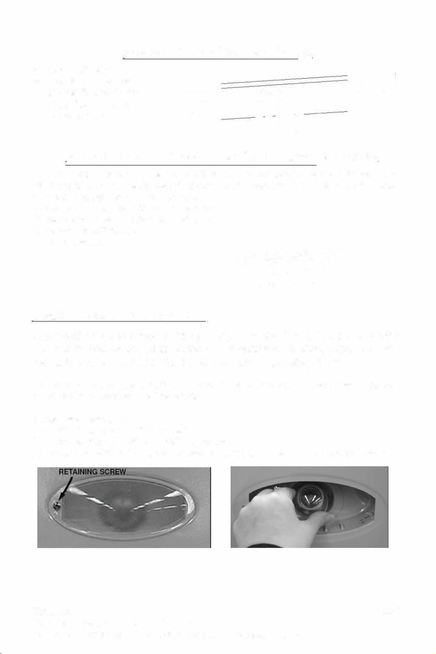
Install of a light bulb
1) Turn o the power of the range hood
2) Unscrew the light diuser retaining screw.
3) Rotate the 40W A-15 type incandescent lamp clockwise into the socket holder
Page: 13
Hauslane
267 Wattis Way, San Francisco, CA 94124
Hauslane
267 Wattis Way, San Francisco, CA 94124
Tel: 1-800-929-0168 E-mail: [email protected]
Step 6 - Electrical Connection
� WARNING
Risk of electrical shock. Electrical wiring must be done by qualied personnel in accord
ance with all applicable codes and standards. Before connecng wires, switch power o at
service panel and lock service disconnecon means to prevent power from being switched
on accidentally.
1. Connect cable to range hood wiring using
wire connectors. Connect BLACK to BLACK,
WHITE to WHITE, GREEN or BARE wire to
GREEN wire.
2. Reinstall wiring box cover.
3. Plug back the small white connector
(aached with the boom panel) inside the
hood.
4. Reinstall boom panel. Make
sure both grease guides are aligned
with the holes.
5. Using long nose pliers, pull out
the end of each grease guides (A).
Then, set them in such a way their
slightly protrudes above the
boom panel surface (B).
6. Install the long grease cup at the
end of the hood bottom.
7. Install the two small round
grease guard cups onto the two
metal guard. Push in and turn
clockwise.
Page: 12
Model: C190 Standard Series
A. Power O Switch
B. Low Speed Switch
C. Middle Speed Switch
D. High Speed Switch
E. Light Switch
r�r r
E D C BA
Model:
C
395 Premium Auto-clean Series
A. Auto-Clean Switch- press once will go into the 38 seconds auto-clean mode. It
will starts to spray the degreaser that stored at the water tank and clean up the fans,
then automatically stop in 38 seconds.
B. Low Speed Switch (6 speed step down)
C. High Speed Switch (6 speed step up)
D. Power On/o Switch
E. Light Switch
B
CD E
Install/ Replace of the Light Bulb
Light bulb is included in this package.
F
or future replacement, this is a
110
/
120
V
, 40W A-15 type incandescent lamp (a
v
ailable at most
hardware stores). We highly recommend using a 3.5W LED light bulb.
RNING - If you use a bulb over 40W, it will seriously caused damage to the
hood and the warranty will be voided!
Install of a light bulb
1) Turn o the power of the range hood
2) Unscrew the light diuser retaining screw.
3) Rotate the 40W A-15 type incandescent lamp clockwise into the socket holder
Page: 13
Hauslane
267 Wattis Way, San Francisco, CA 94124
Tel: 1-800-929-0168 E-mail: [email protected]
Hauslane
267 Wattis Way, San Francisco, CA 94124
Tel: 1-800-929-0168 E-mail: info@hauslane.com
HOOD CLEANING
Stainless steel is known r its ability to be a clean
surface that resists corrosion an rust. Dirt, dust and
grime, however, put stainless at risk r corrosion
and rust. Luckily, stainless steel responds well to
cleaning, never wearing out from excessive clean
ing, as long as certain rules are followed.
1.Water and a cloth. Routine cleaning can be ac
complished by using warm water and a cloth. This
is the least risky option r cleaning stainless steel.
Dry with a towel or cloth to prevent water spots.
Wipe in the directions of the polish lines.
2. Mild detergent, (dish washing liquid) and
cloth. For cleaning that needs more power, mild
detergent and warm water can do a great job with
out damaging the stainless steel. Make sure you
rinse the surface thoroughly to prevent staining and
spotting. Towel dry to prevent water spots which
can be caused by minerals in water.
3. Glass cleaner for fingerprints. Fingerprints are
one of the biggest complaints about stainless steel,
but can be taken care by using glass cleaner or
household ammonia. Rinse thoroughly and towel
dry. There are some newer types of finishes for
stainless steel that resist fingerprints, a must if your
pint-sized helpers leave their mark on your stain
less steel appliances.
4. Stainless Steel Cleaner. If you've had staining
or scratching, or need to polish your stainless steel,
a stainless steel cleaner may be a good option.
Some of these cleaners and polishes can help min
imize scratching and remove stains. They also can
polish stainless steel surfaces nicely. Read the di
rections on the stainless steel cleaner and test in
an inconspicuous spot. Be sure to rinse thoroughly
and towel dry.
Warning- When cleaning the hood, never spray
cleaning agent directly on the controls; spray it
on the cleaning cloth and wipe the control with
it. Spraying cleaning agent directly on the con
trol will cause unexpected keyboard activation.
Do not use any steel or stainless steel wool or any
other scrapers to remove stubborn dirt.
Do not use any harsh or abrasive cleanser.
Do not allow dirt to accumulate.
Do not let plaster dust or any construction resides
reach the hood. During construction or renovation,
cover the hood to make sure no dust sticks to
stainless steel surface.
OID : when choosing a detergent
-Any cleaners that contain bleach will attack stain
less steel.
-Any products containing: chloride, fluoride, io
dide, bromide will deteriorate surfaces rapidly.
-Any combustible products used for cleaning
such as acetone, alcohol, ether, benzol, etc., are
highly explosive and should never be used close to
a range.
Auto-cleaning function
(Only for Model
C
395)
Use the white water kettle provided, mix with 2 por
tion of degreaser (DO NOT USE detergent) and 8
portion of water.
recommend to use 409 degrease
Remove the cap at the top le of the range hood,
Fill in the mixer into the hole (water tank).
It can serve up to 8-10 times of Auto-cleaning func
tion.
Stop to fill if over flow.
Status
Method of fixing
Bulb does
Check the light bulb, some base too flat
not light
cannot touch the base.
Check for damaoed control oanel
Check connection of power plug
Check whether the vane is blocked
Motor does
Lubricate the motor
not work
Repair or replace damaged control panel
Replace the capacitor
Replace the motor
Machine Fasten the body
vibrates Check for damaged vanes
when
Check if the vanes are installed well
switch on
Fasten the motor
Regulate bob-weight or replace the
Big noise
vanes
Check whether some matters drop into
the air chamber, like damper.
Lower the hood properly
Weak sue- Do not open too many windows for im-
lion proving the suction environment
Replace the motor and the capacitor
Oil leakage
Remain the body level
Replace the sealant
Unworka-
Replace the cleaning bump
ble clean-
ing
Replace the control machine
Page: 14
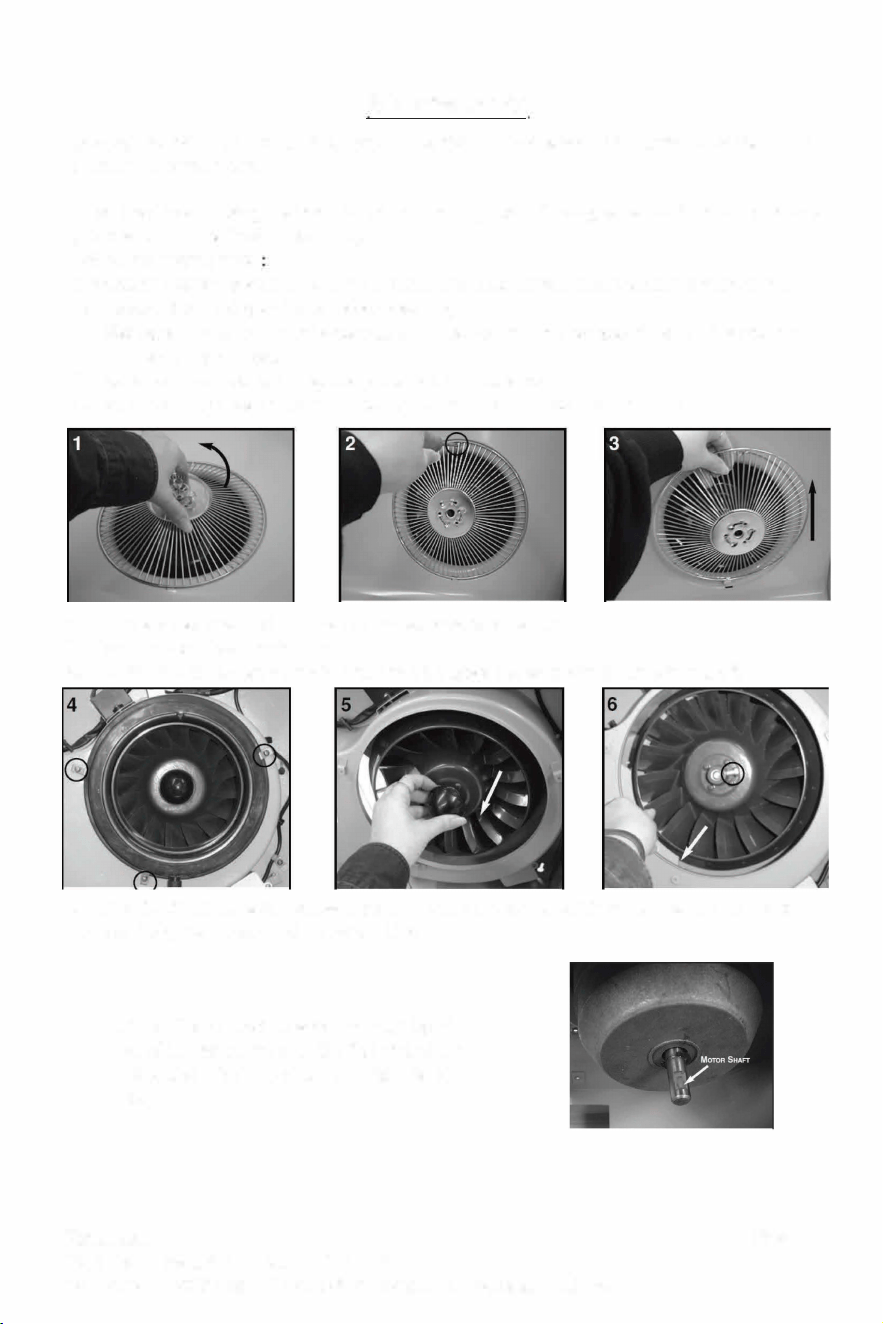
Maintenance
C395 (with Auto-clean funcon) - using this funcon weekly to maintenance the inside
cleanliness of the hood.
Aer long me of using the hood (about 6 months), you will see grease retained at the grease
guard and blowers (inside the hood).
Follow the steps below
Important - Switch power o at service panel and lock service disconnecon means to pre
vent power from being switched on accidentally.
1. Disengage the small round grease guard cups from the grease guard by turning counter
clockwise and remove.
2. Remove the screw retaining the grease guard to the hood.
3. Remove the grease guard from the hood. Then remove the boom panel.
4. Unscrew the clips and remove the wheel grease collector.
5. Remove the wheel center cap.
6. Loosen the wheel set screw in order to disengage the wheel from its motor sha.
Let soak r 30 minutes all removed parts in warm soapy water. Then wash with nylon brush,
rinse and dry completely bere reinstalling.
NOTE: When reinstalling the wheel, align the
end of the set screw with the at part of the
motor sha (see the picture at right hand
side )
Page:15
Hauslane
267 Wattis Way, San Francisco, CA 94124
Hauslane
267 Wattis Way, San Francisco, CA 94124
Tel: 1-800-929-0168 E-mail: [email protected]
HOOD CLEANING
Stainless steel is known r its ability to be a clean
surface that resists corrosion an rust. Dirt, dust and
grime, however, put stainless at risk r corrosion
and rust. Luckily, stainless steel responds well to
cleaning, never wearing out from excessive clean
ing, as long as certain rules are followed.
1.Water and a cloth. Routine cleaning can be ac
complished by using warm water and a cloth. This
is the least risky option r cleaning stainless steel.
Dry with a towel or cloth to prevent water spots.
Wipe in the directions of the polish lines.
2. Mild detergent, (dish washing liquid) and
cloth. For cleaning that needs more power, mild
detergent and warm water can do a great job with
out damaging the stainless steel. Make sure you
rinse the surface thoroughly to prevent staining and
spotting. Towel dry to prevent water spots which
can be caused by minerals in water.
3. Glass cleaner for fingerprints. Fingerprints are
one of the biggest complaints about stainless steel,
but can be taken care by using glass cleaner or
household ammonia. Rinse thoroughly and towel
dry. There are some newer types of finishes for
stainless steel that resist fingerprints, a must if your
pint-sized helpers leave their mark on your stain
less steel appliances.
4. Stainless Steel Cleaner. If you've had staining
or scratching, or need to polish your stainless steel,
a stainless steel cleaner may be a good option.
Some of these cleaners and polishes can help min
imize scratching and remove stains. They also can
polish stainless steel surfaces nicely. Read the di
rections on the stainless steel cleaner and test in
an inconspicuous spot. Be sure to rinse thoroughly
and towel dry.
Warning- When cleaning the hood, never spray
cleaning agent directly on the controls; spray it
on the cleaning cloth and wipe the control with
it. Spraying cleaning agent directly on the con
trol will cause unexpected keyboard activation.
Do not use any steel or stainless steel wool or any
other scrapers to remove stubborn dirt.
Do not use any harsh or abrasive cleanser.
Do not allow dirt to accumulate.
Do not let plaster dust or any construction resides
reach the hood. During construction or renovation,
cover the hood to make sure no dust sticks to
stainless steel surface.
OID : when choosing a detergent
-Any cleaners that contain bleach will attack stain
less steel.
-Any products containing: chloride, fluoride, io
dide, bromide will deteriorate surfaces rapidly.
-Any combustible products used for cleaning
such as acetone, alcohol, ether, benzol, etc., are
highly explosive and should never be used close to
a range.
Auto-cleaning function
(Only for Model
C
395)
Use the white water kettle provided, mix with 2 por
tion of degreaser (DO NOT USE detergent) and 8
portion of water.
recommend to use 409 degrease
Remove the cap at the top le of the range hood,
Fill in the mixer into the hole (water tank).
It can serve up to 8-10 times of Auto-cleaning func
tion.
Stop to fill if over flow.
Status
Method of fixing
Bulb does
Check the light bulb, some base too flat
not light
cannot touch the base.
Check for damaoed control oanel
Check connection of power plug
Check whether the vane is blocked
Motor does
Lubricate the motor
not work
Repair or replace damaged control panel
Replace the capacitor
Replace the motor
Machine Fasten the body
vibrates Check for damaged vanes
when
Check if the vanes are installed well
switch on
Fasten the motor
Regulate bob-weight or replace the
Big noise
vanes
Check whether some matters drop into
the air chamber, like damper.
Lower the hood properly
Weak sue- Do not open too many windows for im-
lion proving the suction environment
Replace the motor and the capacitor
Oil leakage
Remain the body level
Replace the sealant
Unworka-
Replace the cleaning bump
ble clean-
ing
Replace the control machine
Page: 14
Maintenance
C395 (with Auto-clean funcon) - using this funcon weekly to maintenance the inside
cleanliness of the hood.
Aer long me of using the hood (about 6 months), you will see grease retained at the grease
guard and blowers (inside the hood).
Follow the steps below
Important - Switch power o at service panel and lock service disconnecon means to pre
vent power from being switched on accidentally.
1. Disengage the small round grease guard cups from the grease guard by turning counter
clockwise and remove.
2. Remove the screw retaining the grease guard to the hood.
3. Remove the grease guard from the hood. Then remove the boom panel.
4. Unscrew the clips and remove the wheel grease collector.
5. Remove the wheel center cap.
6. Loosen the wheel set screw in order to disengage the wheel from its motor sha.
Let soak r 30 minutes all removed parts in warm soapy water. Then wash with nylon brush,
rinse and dry completely bere reinstalling.
NOTE: When reinstalling the wheel, align the
end of the set screw with the at part of the
motor sha (see the picture at right hand
side )
Page:15
Hauslane
267 Wattis Way, San Francisco, CA 94124
Tel: 1-800-929-0168 E-mail: [email protected]
Hauslane
267 Wattis Way, San Francisco, CA 94124
Tel: 1-800-929-0168 E-mail: info@hauslane.com
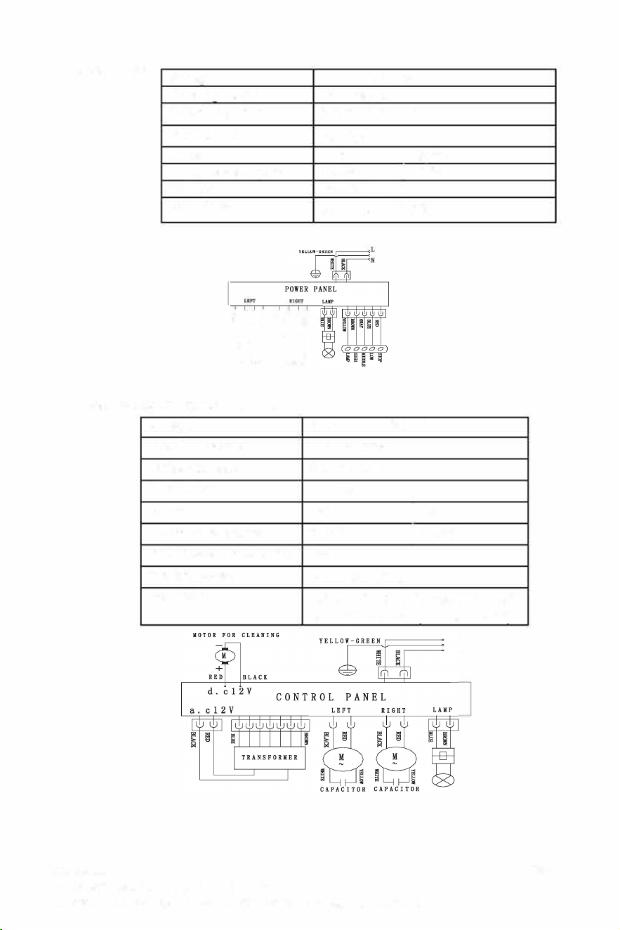
Model:
C
190
ltaae
110V -120V / 60Hz
Rotatina method
in Motors
Outlet diameter
6 Inch (150mm)
Illumination
4ow
Motor
Le
I Right
Power consumption
100W
I100w
Air Flow
250-750 CFM
Body Size
30"X 22" X 7-7/8"
{ti� �t;��
88
CAPACIOI
CAPCITOl
Model:
C
395 (with Auto-Clean)
Voltage
Rotating method
Outlet diameter
Illumination
Motor
Power consumption
Input power r cleaning
Suction power
110V-120V- /60Hz
in Motors
6 Inch (150mm)
40W
Le
I
Right
100W
I
100w
8W
810 ± 50 m
3
thr
Body Size
30"X 22"X 7-7/8"
36" x 22" x 7-7/8"
L
N
Page: 16
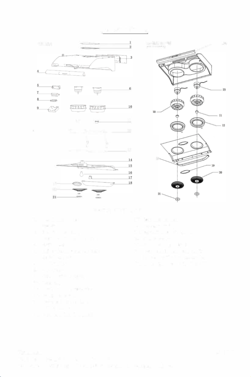
Service Parts
C
190
TA-395 I TA-495
�
22
(anto-cleanv�nton)
�
19
20
==r�r
(\
((
11
12
=
=--
-
�13
18
Parts number
1. Top Shuto plate
2. Gasket
3. Rear Shuto plate
4. Front plastic panel (C190)
5. Switch box
6. Le or right motor (C190)
7. Switch box cover
8. Push buon
9. PCB cover
10. Vane (Le and right)
11. Vane cap
12. Inside round grease tray
13. Plasc rubber ring
14. Light bulb socket holder
15. Boom panel
16. Light bulb (not included)
17. Light bu I b socket
18. Long grease cup
19. Light diuser with screw
20. Grease guard
21. Small round grease cup
22. Front plastic panel with switch
(
U
C-C395SS-30 <30"> /
U
C-
C395SS-36 <36">)
23. Le or right motor (C395)
Page: 17
Hauslane
267 Wattis Way, San Francisco, CA 94124
Hauslane
267 Wattis Way, San Francisco, CA 94124
Tel: 1-800-929-0168 E-mail: [email protected]
Model:
C
190
ltaae
110V -120V / 60Hz
Rotatina method
in Motors
Outlet diameter
6 Inch (150mm)
Illumination
4ow
Motor
Le
I Right
Power consumption
100W
I100w
Air Flow
250-750 CFM
Body Size
30"X 22" X 7-7/8"
{ti� �t;��
88
CAPACIOI
CAPCITOl
Model:
C
395 (with Auto-Clean)
Voltage
Rotating method
Outlet diameter
Illumination
Motor
Power consumption
Input power r cleaning
Suction power
110V-120V- /60Hz
in Motors
6 Inch (150mm)
40W
Le
I
Right
100W
I
100w
8W
810 ± 50 m
3
thr
Body Size
30"X 22"X 7-7/8"
36" x 22" x 7-7/8"
L
N
Page: 16
Service Parts
C
190
TA-395 I TA-495
�
22
(anto-cleanv�nton)
�
19
20
==r�r
(\
((
11
12
=
=--
-
�13
18
Parts number
1. Top Shuto plate
2. Gasket
3. Rear Shuto plate
4. Front plastic panel (C190)
5. Switch box
6. Le or right motor (C190)
7. Switch box cover
8. Push buon
9. PCB cover
10. Vane (Le and right)
11. Vane cap
12. Inside round grease tray
13. Plasc rubber ring
14. Light bulb socket holder
15. Boom panel
16. Light bulb (not included)
17. Light bu I b socket
18. Long grease cup
19. Light diuser with screw
20. Grease guard
21. Small round grease cup
22. Front plastic panel with switch
(
U
C-C395SS-30 <30"> /
U
C-
C395SS-36 <36">)
23. Le or right motor (C395)
Page: 17
Hauslane
267 Wattis Way, San Francisco, CA 94124
Tel: 1-800-929-0168 E-mail: [email protected]
Hauslane
267 Wattis Way, San Francisco, CA 94124