
Tyre and Axle Recognition Unit
User Manual

Tyre and Axle Recognition Unit User Manual
i
Initiatives on the Use of Video Products
Thank you for choosing Hikvision products.
Technology affects every aspect of our life. As a high-tech company, we are increasingly aware of
the role technology plays in improving business efficiency and quality of life, but at the same time,
the potential harm of its improper usage. For example, video products are capable of recording
real, complete and clear images. This provides a high value in retrospect and preserving real-time
facts. However, it may also result in the infringement of a third party's legitimate rights and
interests if improper distribution, use and/or processing of video data takes place. With the
philosophy of "Technology for the Good", Hikvision requests that every end user of video
technology and video products shall comply with all the applicable laws and regulations, as well as
ethical customs, aiming to jointly create a better community.
Please read the following initiatives carefully:
●
Everyone has a reasonable expectation of privacy, and the installation of video products should
not be in conflict with this reasonable expectation. Therefore, a warning notice shall be given in
a reasonable and effective manner and clarify the monitoring range, when installing video
products in public areas. For non-public areas, a third party's rights and interests shall be
evaluated when installing video products, including but not limited to, installing video products
only after obtaining the consent of the stakeholders, and not installing highly-invisible video
products.
●
The purpose of video products is to record real activities within a specific time and space and
under specific conditions. Therefore, every user shall first reasonably define his/her own rights
in such specific scope, in order to avoid infringing on a third party's portraits, privacy or other
legitimate rights.
●
During the use of video products, video image data derived from real scenes will continue to be
generated, including a large amount of biological data (such as facial images), and the data
could be further applied or reprocessed. Video products themselves could not distinguish good
from bad regarding how to use the data based solely on the images captured by the video
products. The result of data usage depends on the method and purpose of use of the data
controllers. Therefore, data controllers shall not only comply with all the applicable laws and
regulations and other normative requirements, but also respect international norms, social
morality, good morals, common practices and other non-mandatory requirements, and respect
individual privacy, portrait and other rights and interests.
●
The rights, values and other demands of various stakeholders should always be considered
when processing video data that is continuously generated by video products. In this regard,
product security and data security are extremely crucial. Therefore, every end user and data
controller, shall undertake all reasonable and necessary measures to ensure data security and
avoid data leakage, improper disclosure and improper use, including but not limited to, setting
up access control, selecting a suitable network environment (the Internet or Intranet) where
video products are connected, establishing and constantly optimizing network security.

Tyre and Axle Recognition Unit User Manual
ii
●
Video products have made great contributions to the improvement of social security around the
world, and we believe that these products will also play an active role in more aspects of social
life. Any abuse of video products in violation of human rights or leading to criminal activities are
contrary to the original intent of technological innovation and product development. Therefore,
each user shall establish an evaluation and tracking mechanism of their product application to
ensure that every product is used in a proper and reasonable manner and with good faith.
Tyre and Axle Recognition Unit User Manual
iii
Symbol Conventions
The symbols that may be found in this document are defined as follows.
Symbol
Description
Danger
Indicates a hazardous situation which, if not avoided, will or could
result in death or serious injury.
Caution
Indicates a potentially hazardous situation which, if not avoided,
could result in equipment damage, data loss, performance
degradation, or unexpected results.
Note
Provides additional information to emphasize or supplement
important points of the main text.

Tyre and Axle Recognition Unit User Manual
iv
Contents
Chapter 1 Product Introduction .................................................................................................. 1
1.1
Product Introduction .......................................................................................................... 1
1.2 Product Features .................................................................................................................. 1
Chapter 2 Activation and Login ................................................................................................... 2
2.1 Activation .............................................................................................................................. 2
2.1.1 Default Information ................................................................................................... 2
2.1.2 Activate via SADP ....................................................................................................... 2
2.1.3 Activate via Web Browser .......................................................................................... 3
2.2 Login ..................................................................................................................................... 4
Chapter 3 Capture Configuration ................................................................................................ 5
3.1 Set Smart Monitoring Capture .............................................................................................. 5
3.2 Set Capture Parameters ........................................................................................................ 6
3.2.1 Set License Plate Recognition Parameters ................................................................. 6
3.2.2 Set Supplement Light Parameters ............................................................................. 7
3.2.3 Set Picture Composition ............................................................................................ 8
3.2.4 Set Information Overlay ............................................................................................. 9
3.2.5 Set Face Picture Matting .......................................................................................... 10
3.2.6 Set Vehicle Feature Parameters .............................................................................. 11
3.2.7 Set Image Encoding Parameters .............................................................................. 12
Chapter 4 View Traffic Statistics ................................................................................................ 13
4.1 Search Picture ..................................................................................................................... 13
4.2 View Real-Time Picture ....................................................................................................... 13
4.3 View Real-Time Traffic Statistics ......................................................................................... 15
Chapter 5 Live View and Local Configuration ............................................................................. 16
5.1 Live View ............................................................................................................................. 16
5.1.1 Start/Stop Live View ................................................................................................ 16
5.1.2 Select Live View Ratio .............................................................................................. 16
5.1.3 Select Window Division Mode ................................................................................. 16

Tyre and Axle Recognition Unit User Manual
v
5.1.4 Select Stream Type .................................................................................................. 16
5.1.5 Capture Picture Manually ........................................................................................ 16
5.1.6 Record Manually ...................................................................................................... 17
5.1.7 Enable Digital Zoom ................................................................................................. 17
5.1.8 Select Video Mode ................................................................................................... 17
5.1.9 Enable Full Screen .................................................................................................... 17
5.1.10 BLC ......................................................................................................................... 17
5.2 Local Configuration ............................................................................................................. 18
Chapter 6 Playback ................................................................................................................... 21
Chapter 7 Record and Capture .................................................................................................. 22
7.1 Set Storage Path ................................................................................................................. 22
7.1.1 Set Storage Card ...................................................................................................... 22
7.1.2 Set FTP ..................................................................................................................... 23
7.1.3 Set SDK Listening ..................................................................................................... 24
7.1.4 Set Arm Host ............................................................................................................ 25
7.1.5 Set ISAPI Listening .................................................................................................... 26
7.1.6 Set Cloud Storage ..................................................................................................... 27
7.2 Set Quota ............................................................................................................................ 28
7.3 Set Record Schedule ........................................................................................................... 29
Chapter 8 Encoding and Display ................................................................................................ 31
8.1 Set Video Encoding Parameters .......................................................................................... 31
8.2 Set Image Parameters ......................................................................................................... 32
8.3 Set ROI ................................................................................................................................ 34
8.4 Set OSD ............................................................................................................................... 35
8.5 Set Privacy Mask ................................................................................................................. 36
Chapter 9 Network Configuration ............................................................................................. 38
9.1 Set IP Address ..................................................................................................................... 38
9.2 Connect to ISUP Platform ................................................................................................... 40
9.3 Set DDNS ............................................................................................................................. 42
9.4 Set SNMP ............................................................................................................................ 43
9.5 Set Port ............................................................................................................................... 43

Tyre and Axle Recognition Unit User Manual
vi
9.6 Set 802.1 X .......................................................................................................................... 45
9.7 Set QoS ............................................................................................................................... 45
Chapter 10 Serial Port Configuration ......................................................................................... 47
10.1 Set RS-485 ......................................................................................................................... 47
10.2 Set RS-232 ......................................................................................................................... 48
Chapter 11 Event and Alarm ..................................................................................................... 49
11.1 Exception Alarm ................................................................................................................ 49
11.2 Set Email ........................................................................................................................... 49
Chapter 12 Safety Management ................................................................................................ 52
12.1 Manage User ..................................................................................................................... 52
12.2 Set IP Address Filtering ..................................................................................................... 53
12.3 Enable User Lock ............................................................................................................... 53
12.4 Set HTTPS .......................................................................................................................... 53
12.4.1 Create and Install Self-signed Certificate ............................................................... 53
12.4.2 Install Authorized Certificate ................................................................................. 54
12.5 Set SSH .............................................................................................................................. 54
12.6 Set RTSP Authentication ................................................................................................... 55
12.7 Set Timeout Logout .......................................................................................................... 55
12.8 Set Password Validity Period ............................................................................................ 55
Chapter 13 Maintenance .......................................................................................................... 56
13.1 View Device Information .................................................................................................. 56
13.2 Log .................................................................................................................................... 56
13.2.1 Enable System Log Service ..................................................................................... 56
13.2.2 Search Log .............................................................................................................. 56
13.2.3 Enable Log According to Module ........................................................................... 57
13.3 Upgrade ............................................................................................................................ 57
13.4 Reboot .............................................................................................................................. 58
13.5 Restore Parameters .......................................................................................................... 58
13.6 Synchronize Time .............................................................................................................. 58
13.7 Set DST .............................................................................................................................. 59
13.8 Debug ................................................................................................................................ 59

Tyre and Axle Recognition Unit User Manual
vii
13.8.1 Debug Device ......................................................................................................... 59
13.8.2 Vehicle Capture and Recognition Service .............................................................. 60
13.8.3 Set Image Format ................................................................................................... 61
13.9 Export Parameters ............................................................................................................ 61
13.10 Import Configuration File ............................................................................................... 62
13.11 Export Debug File ............................................................................................................ 62
13.12 Export Diagnosis Information ......................................................................................... 62

Tyre and Axle Recognition Unit User Manual
1
Chapter 1 Product Introduction
1.1 Product Introduction
Tyre and Axle Recognition Unit (hereinafter referred to as device) has shield and high-definition
camera. The device has high frame rate, good color reproduction and low illumination. The device
adopts "deep learning" algorithm, which can be widely used in highway and park vehicle axle
recognition and license plate recognition.
1.2 Product Features
Some functions are dependent on the model. Please refer to the actual device.
●
Supports wheel axle and tyre type recognition.
●
Supports vehicle body text and container number recognition.
●
Supports connecting supplement light.
●
Supports uploading data remotely.
●
Dustproof, waterproof, anti-surge and etc.

Tyre and Axle Recognition Unit User Manual
2
Chapter 2 Activation and Login
2.1 Activation
For the first-time access, you need to activate the device by setting an admin password. No
operation is allowed before activation. The device supports multiple activation methods, such as
activation via SADP software, web browser, and iVMS-4200 Client.
Note
Refer to the user manual of iVMS-4200 Client for the activation via client software.
2.1.1 Default Information
The device default information is shown as below.
●
Default IP address: 192.168.1.64
●
Default user name: admin
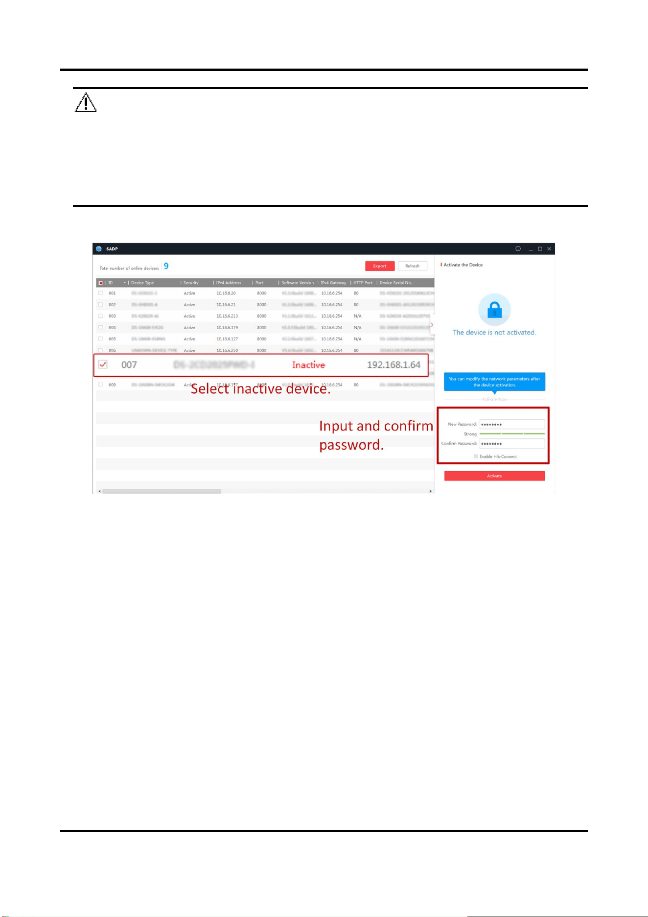
2.1.2 Activate via SADP
SADP is a tool to detect, activate, and modify the IP address of the device over the LAN.
Before You Start
●
Get the SADP software from the supplied disk or the official website
(http://www.hikvision.com/), and install it according to the prompts.
●
The device and the computer that runs the SADP tool should belong to the same network
segment.
The following steps show how to activate one device and modify its IP address. For batch
activation and IP address modification, refer to User Manual of SADP for details.
Steps
1. Run the SADP software and search the online devices.
2. Find and select your device in online device list.
3. Enter a new password (admin password) and confirm the password.
Tyre and Axle Recognition Unit User Manual
3
Caution
STRONG PASSWORD RECOMMENDED-We highly recommend you create a strong password of
your own choosing (using a minimum of 8 characters, including upper case letters, lower case
letters, numbers, and special characters) in order to increase the security of your product. And
we recommend you reset your password regularly, especially in the high security system,
resetting the password monthly or weekly can better protect your product.
4. Click Activate to start activation.
Figure 2-1 Activate via SADP
Status of the device becomes Active after successful activation.
5. Modify IP address of the device.
1) Select the device.
2) Change the device IP address to the same network segment as your computer by either
modifying the IP address manually or checking Enable DHCP (Dynamic Host Configuration
Protocol).
3) Enter the admin password and click Modify to activate your IP address modification.
2.1.3 Activate via Web Browser
Use web browser to activate the device. For the device with the DHCP enabled by default, use
SADP software or client software to activate the device.
Before You Start
Ensure the device and the computer are in the LAN with the same network segment.

Tyre and Axle Recognition Unit User Manual
4
Steps
1. Change the IP address of your computer to the same network segment as the device.
2. Open the web browser, and enter the default IP address of the device to enter the activation
interface.
3. Create and confirm the admin password.
Caution
STRONG PASSWORD RECOMMENDED-We highly recommend you create a strong password of
your own choosing (using a minimum of 8 characters, including upper case letters, lower case
letters, numbers, and special characters) in order to increase the security of your product. And
we recommend you reset your password regularly, especially in the high security system,
resetting the password monthly or weekly can better protect your product.
4. Click OK to complete activation.
5. Go to the network settings interface to modify IP address of the device.
2.2 Login
You can log in to the device via web browser for further operations such as live view and local
configuration.
Before You Start
Connect the device to the network directly, or via a switch or a router.
Steps
1. Open the web browser, and enter the IP address of the device to enter the login interface.
2. Enter User Name and Password.
3. Click Login.
4. Download and install appropriate plug-in for your web browser. Follow the installation prompts
to install the plug-in.
5. Reopen the web browser after the installation of the plug-in and repeat steps 1 to 3 to login.
6. Optional: Click Logout on the upper right corner of the interface to log out of the device.
Tyre and Axle Recognition Unit User Manual
5
Chapter 3 Capture Configuration
3.1 Set Smart Monitoring Capture
The smart monitoring mode supports capturing motor vehicles, non-motor vehicles, and
pedestrians via video triggering.
Steps
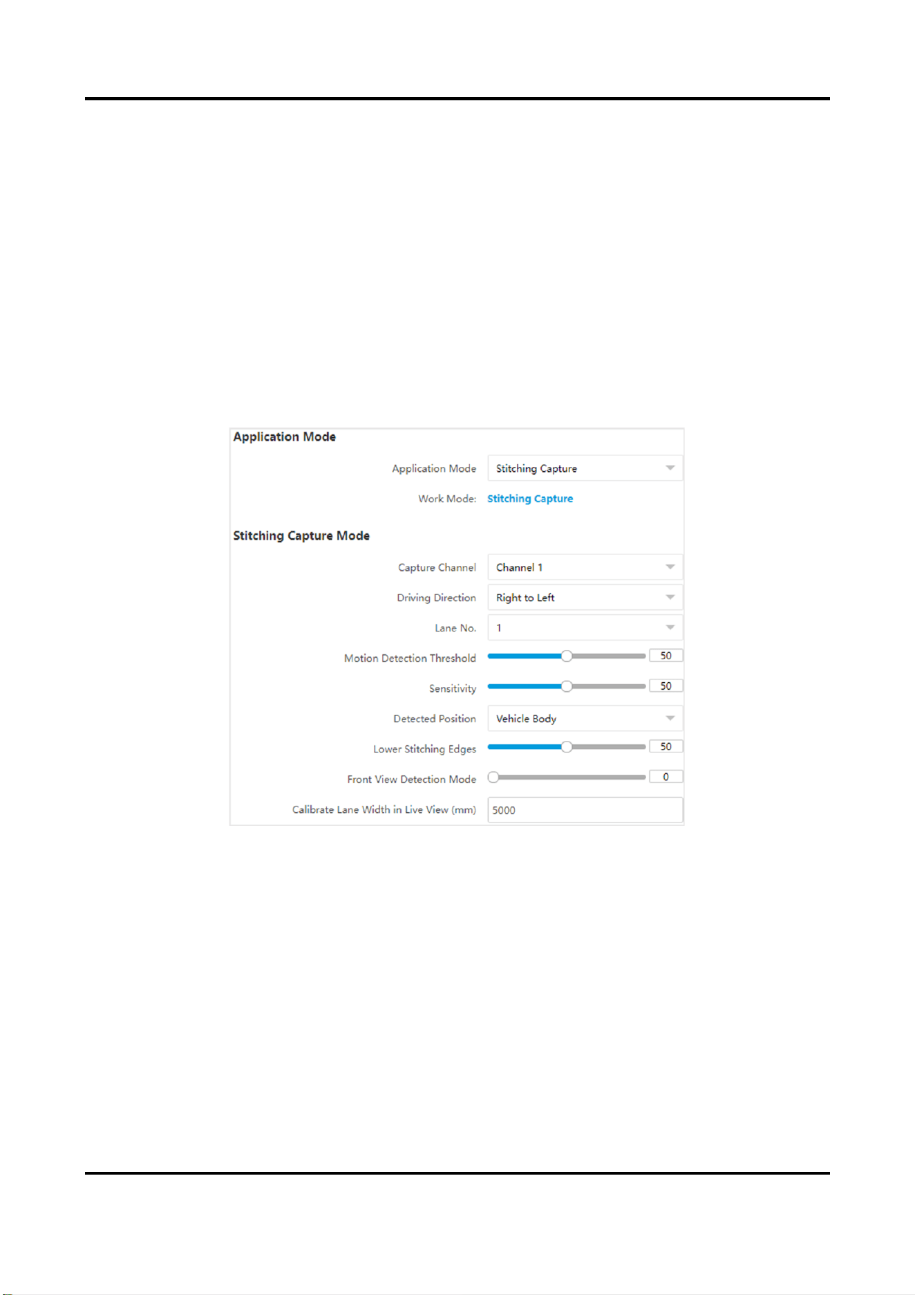
1. Go to Configuration → Capture → Application Mode.
2. Select Application Mode as Stitching Capture.
Figure 3-1 Set Smart Monitoring Capture
3. Set parameters.
Driving Direction
The driving direction of the vehicle
。
Lane No.
The corresponding lane No. linked with the current lane. The lane No. will be overlaid on the
captured picture.
Motion Detection Threshold
It is the position of the upper lane line boundary in the image.
Sensitivity
Tyre and Axle Recognition Unit User Manual
6
It is used to adjust stitching completeness. The larger the value is the more complete the
image stitching will be.
Lower Stitching Edges
It is used to adjust the stitching targets amount and the default value is 50.
Front View Detection Mode
It is used to optimize the stitching image and the default value is 0.
Calibrate Lane Width in Live View (mm)
The distance from the leftmost to the rightmost side of the lane in the image.
6. Optional: Check the other lane(s) to copy the same settings.
7. Draw lane lines.
1) Click Draw Lane Line.
2) Select the default lane lines, trigger line, and right border line, and drag the two end points of
the line or drag the whole line to adjust its position according to the actual scene.
3) Click OK.
8. Click Save.
3.2 Set Capture Parameters
3.2.1 Set License Plate Recognition Parameters
When there are vehicles of different types passing from different directions, set the license plate
recognition parameters.
Steps
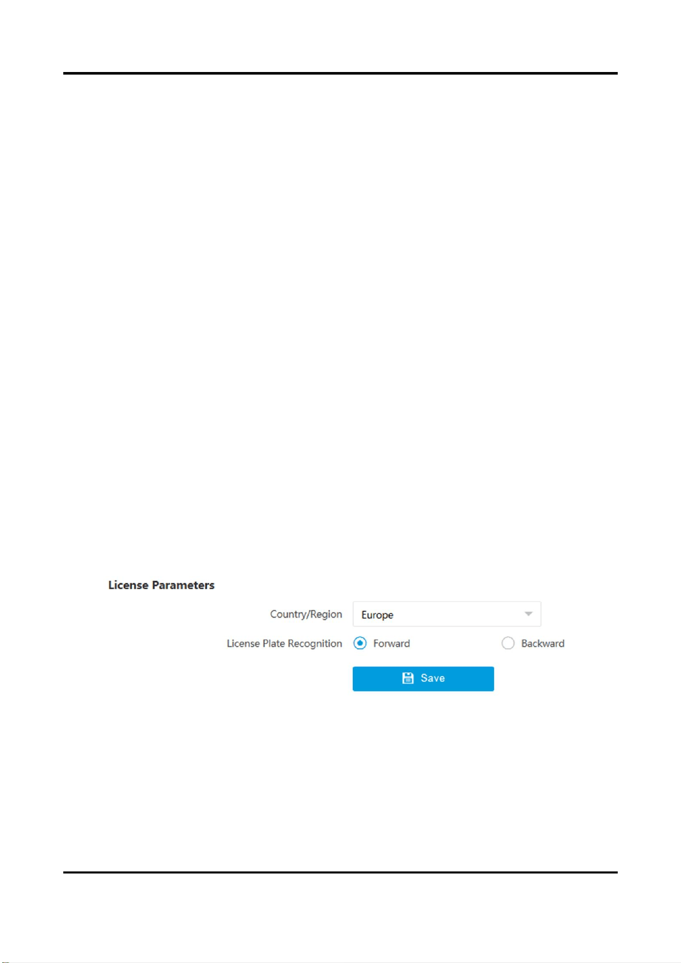
1. Go to Configuration → Capture → Capture Parameters → License Parameters.
Figure 3-2 Set License Plate Recognition Parameters
2. Set Country/Region according to the actual needs.
3. Select License Plate Recognition.
–
Select Forward when license plates of vehicles from the approaching direction need to be
recognized.
–
Select Backward when license plates of vehicles from the leaving direction need to be
recognized.
Tyre and Axle Recognition Unit User Manual
7
4. Click Save.
3.2.2 Set Supplement Light Parameters
Supplement light can enhance the image stabilization and adjust the brightness and color
temperature.
Steps
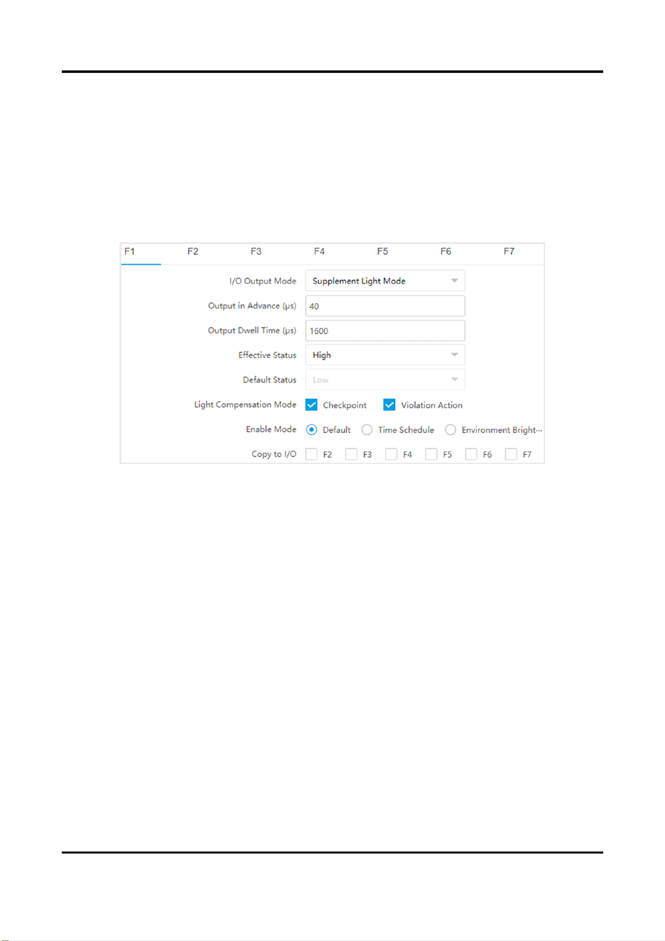
1. Go to Configuration → Capture → Capture Parameters → Supplement Light Parameters.
Figure 3-3 Set Supplement Light Parameters
2. Select the I/O and set the supplement light parameters.
Output in Advance
It is used to adjust time difference between device pulsing and supplement light discharging,
which will improve light effect in capture.
Output Dwell Time
Light flashing duration.
Effective Status
Choose according to actual status.
High/Low
The light will flash when the level signal is high or low.
Pulse
The light will flash when there is pulse signal.
Light Compensation Mode
Please check Checkpoint or Violation Action according to actual needs.
3. Set the supplement light control mode.
–
Select Default to disable the supplement light.
Tyre and Axle Recognition Unit User Manual
8
–
Select Time Schedule when you want the supplement light to be enabled during a fixed time
period. Set the start time and end time.
–
Select Environment Brightness when you want the supplement light to be controlled by
detecting the surroundings brightness automatically. Set the brightness threshold. The higher
the threshold is, the harder the supplement light can be enabled.
Note
The modes conflict with each other. You can only enable one mode.
4. Optional: Check other I/O(s) to copy the same settings.
5. Click Save.
3.2.3 Set Picture Composition
You can enable the picture composition to composite several pictures into one to make it
convenient to view the violation captured pictures.
Steps
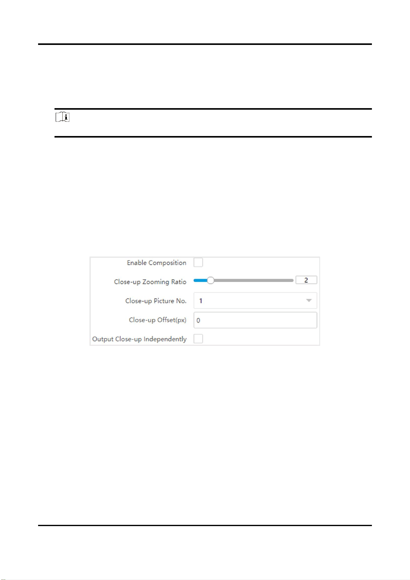
1. Go to Configuration → Capture → Capture Parameters → Image Encoding and Composition →
Image Composition.
Figure 3-4 Set Picture Composition
2. Check Enable Composition.
3. Set composition types for different picture quantities.
4. Set other composition parameters.
Close-up Zooming Ratio
The higher the value is, the larger the close-up is.
Close-up Picture No.
It is the picture where the close-up comes from.
Plate Close-up Offset
The default value is 0, which is recommended to be adopted. The device can capture close-up
pictures according to the set offset when no license plate is recognized.
5. Optional: Check Output Close-up Independently to output close-up pictures independently
when the picture composition is not enabled.
Tyre and Axle Recognition Unit User Manual
9
Note
Enabling composition and outputting close-up independently functions conflict with each other.
You can only enable one.
6. Click Save.
3.2.4 Set Information Overlay
If you want to overlay information on the captured single pictures, set capture overlay.
Steps
Note
The supported parameters vary with different models. The actual device prevails.
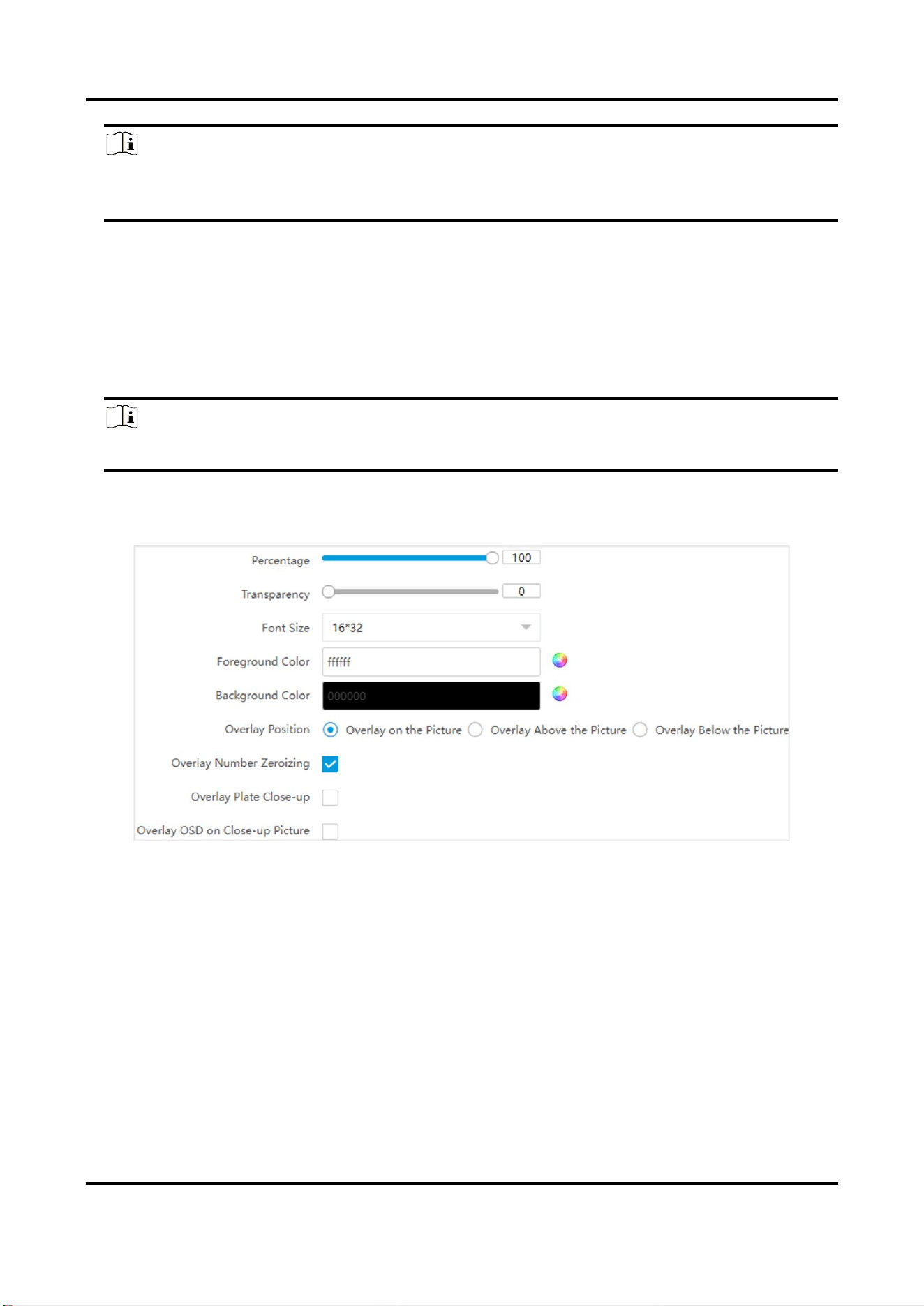
1. Go to Configuration → Capture → Capture Parameters → Text Overlay.
2. Check Capture Picture Overlay.
Figure 3-5 Set Single Picture Overlay
3. Set the percentage, front size, color, overlay position, etc.
Percentage
It is the percentage that the overlaid information occupies on the picture. For example, if you
set the percentage to 50, the overlaid information in a row will occupy up to half of the image
width, and the excess content will be overlaid from a new line.
Transparency
It is the condition of viewing the live view image through the overlaid information.
Overlay Number Zeroizing
When the overlaid number digits are smaller than the fixed digits, 0 will be overlaid before

Tyre and Axle Recognition Unit User Manual
10
the overlaid number. E.g., the fixed digits for lane No. is 2. If the lane No. is 1, 01 will be
overlaid on the picture.
Overlay Plate Close-up
Check it to overlay license plate close-up pictures on the captured pictures.
Overlay OSD on Close-up Picture
Check it to overlay the OSD information on the close-up pictures.
4. Select the overlay information from the list.
Note
The overlay information varies with different models. The actual device prevails.
5. Set the overlay information.
Set Type
You can edit the type.
Set Overlay
Information
For some information types, you can edit the detailed information.
Set Overlay Position
If you check it, the current information will be displayed from a new
line.
Set Space
Edit the number of space between the current information and the
next one from 0 to 255. 0 means there is no space.
Set Line Break
Characters
Edit the number of characters from 0 to 100 between the current
information line and the previous information line. 0 means no line
break.
Adjust overlay
sequence
Click / to adjust the display sequence of the overlay
information.
6. Click Save.
3.2.5 Set Face Picture Matting
Set face picture matting first if you need to upload face and vehicle pictures to the platform.
Steps
Note
The function varies with different models. The actual device prevails.
1. Go to Configuration → Capture → Capture Parameters → Vehicle Feature → Face Picture
Matting.
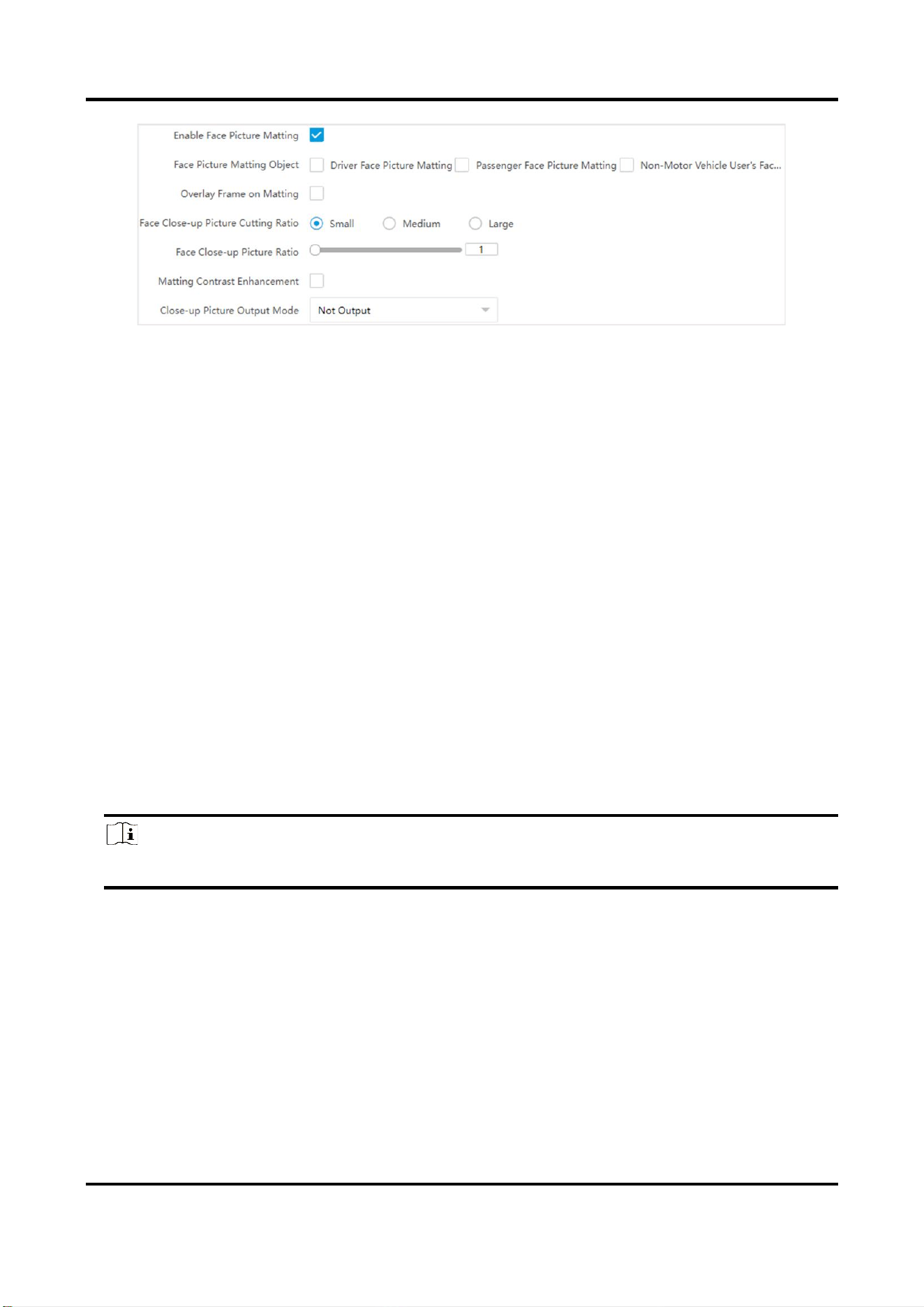
2. Check Enable Face Picture Matting.
Tyre and Axle Recognition Unit User Manual
11
Figure 3-6 Set Face Picture Matting
3. Check Face Picture Matting Object and Overlay Frame on Matting according to the actual
needs.
4. Set other parameters.
Face Close-up Picture Cutting Ratio
The higher the level is, the higher the cutting ratio will be.
Face Close-up Picture Ratio
The higher the value is, the higher the zoom level will be.
Matting Contrast Enhancement
Check Matting Contrast Enhancement and set Matting Contrast Enhancement Level. The
higher the value is, the higher the contrast level will be.
5. Set Close-up Picture Output Mode.
6. Click Save.
3.2.6 Set Vehicle Feature Parameters
Set vehicle feature parameters if you need to detect the vehicle features of the passing vehicle.
Steps
Note
The parameters vary with different models. The actual device prevails.
1. Go to Configuration → Capture → Capture Parameters → Vehicle Feature → Vehicle Feature.
2. Check Vehicle Color Recognition if you want to recognize the vehicle color.
3. Check Enable Vehicle Manufacturer Recognition if you want to recognize the vehicle
manufacturer.
4. Check Non-Motor Vehicle User Wearing Helmet Detection and set sensitivity level if you want
to recognize the helmet wearing condition.
5. Set Steering Wheel Location according to the actual condition.
6. Click Save.
Tyre and Axle Recognition Unit User Manual
12
3.2.7 Set Image Encoding Parameters
If the captured pictures are not clear, set the resolution of the captured pictures and the picture
size.
Steps
1. Go to Configuration → Capture → Capture Parameters → Image Encoding and Composition →
Image Encoding.
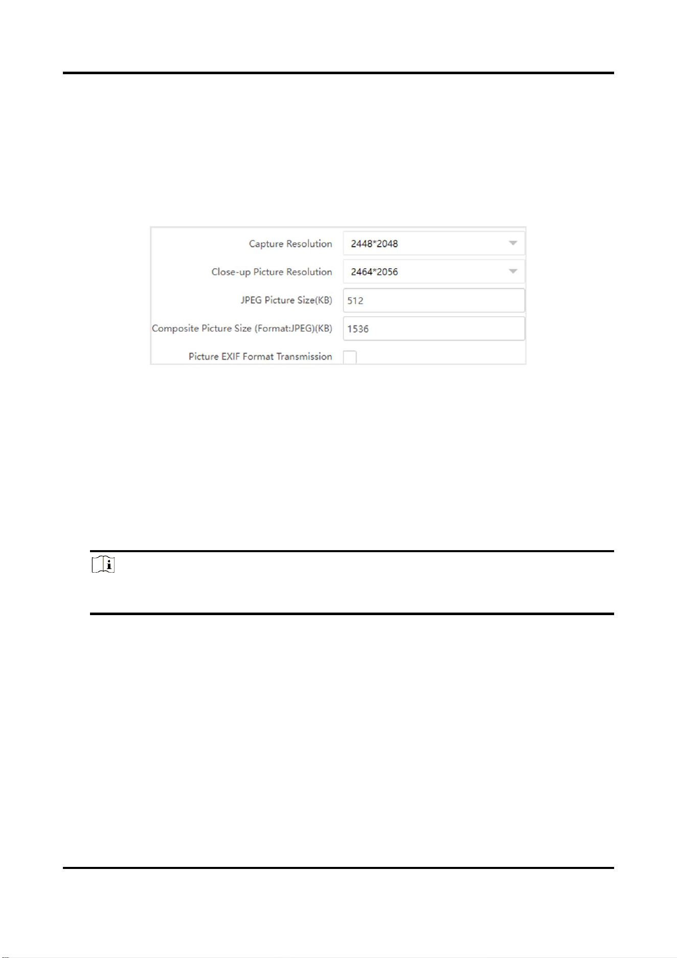
Figure 3-7 Set Image Encoding Parameters
2. Select Capture Resolution and Close-up Picture Resolution.
3. Enter the picture size.
JPEG Picture Size
The size of the compressed captured picture. The actual size is related to the scene
complexity.
Composite Picture Size
The size of the compressed composite picture. The actual size is related to the scene
complexity.
Note
Only the device supporting picture composition supports composite picture size settings. The
actual device prevails.
Picture EXIF Format Transmission
The captured pictures will be transmitted in the EXIF format.
4. Click Save.

Tyre and Axle Recognition Unit User Manual
13
Chapter 4 View Traffic Statistics
4.1 Search Picture
You can search the captured pictures stored in the storage card and export the pictures you need.
Before You Start
Install the storage card, and ensure the storage status is normal.
Steps
1. Click Picture.
2. Set search conditions.
Note
Search conditions vary with different models. The actual device prevails.
3. Click Search.
The searched pictures information will be displayed in the picture list.
Note
If you have set level 1 arming for the device, the captured pictures will not be saved in the
storage card. Go to the saving path of scene pictures to view them. You can go to Configuration
→ Local to check the saving path.
4. Optional: Check picture(s) and click Download to save them to local.
The downloaded picture(s) will be marked as "Downloaded". You can go to Configuration →
Local to check the saving path.
4.2 View Real-Time Picture
You can view the real-time captured pictures and license plate information.
Steps
1. Go to Live View → Real-Time Capture.
2. Click Arming.
3. Select an item from the list, and you can view the capture scene picture and license plate
picture.
Tyre and Axle Recognition Unit User Manual
14
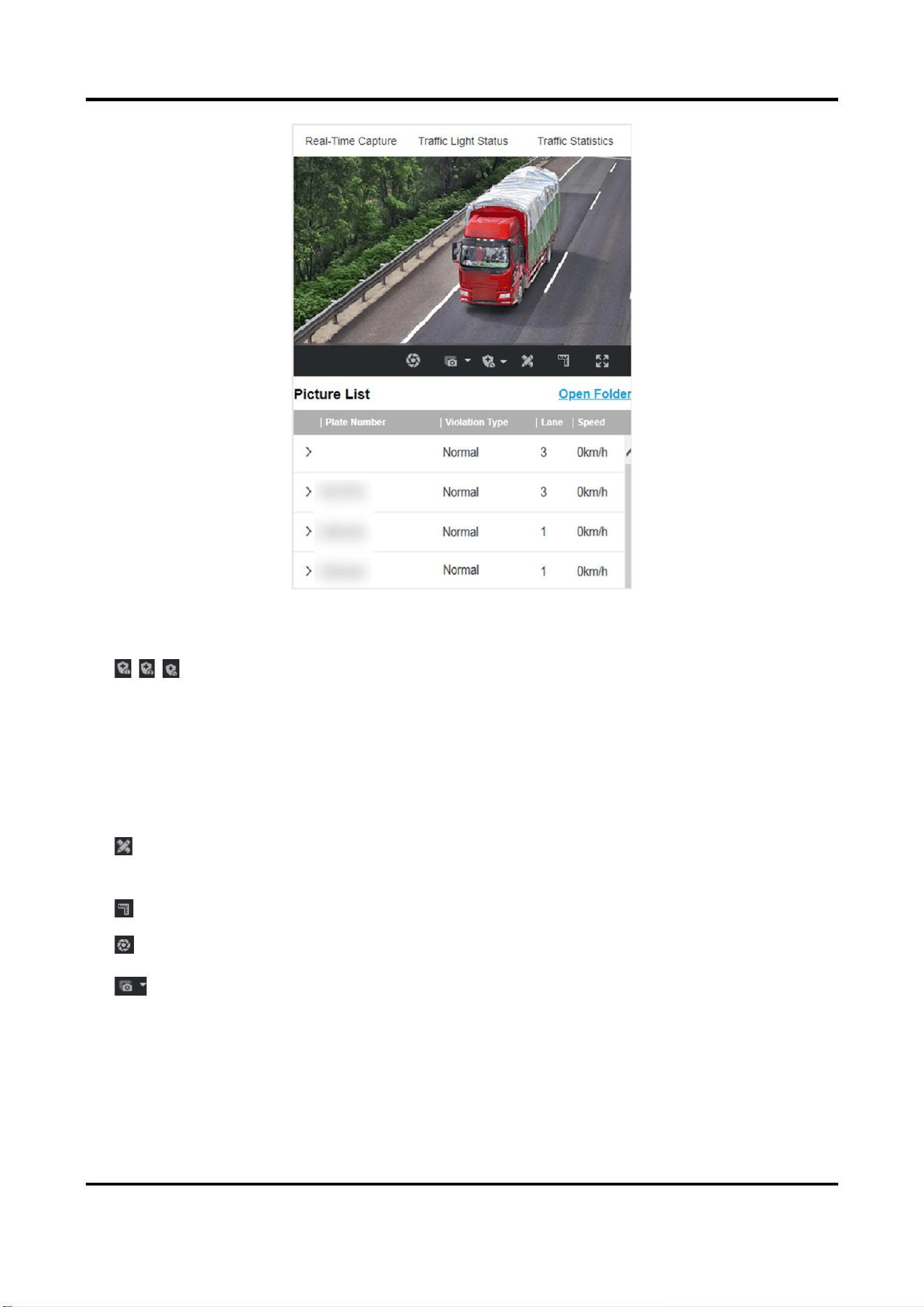
Figure 4-1 Real-Time Picture
4. Optional: You can also do the following operations.
/ /
●
Level 1 Arming can only connect one client or web. The uploaded
pictures will not be stored in the storage card. The pictures in the
storage card will be uploaded to the level 1 arming.
●
Level 2 Arming can connect three clients or webs. The pictures will
be uploaded to the client/web, and stored in the storage card.
●
Disarming is to cancel the alarm status or real-time picture.
Click it to measure the license plate pixel. Click it again to disable the
measurement.
Click it to enable the ruler to measure the license plate.
Click it to enable manual capture.
Click it to set continuous capture parameters and the device will
capture pictures according to the set interval.
●
Capture Times: Up to five pictures can be captured per continuous
capture.
●
Interval: Up to four intervals can be set, and the default interval is
100 ms.

Tyre and Axle Recognition Unit User Manual
15
Display the images in full screen mode.
Open Folder
Open the saving path of captured pictures.
4.3 View Real-Time Traffic Statistics
You can view the real-time traffic statistics if the device supports this function.
Steps
1. Go to Configuration → Capture → Advanced → Traffic Parameters.
2. Check Enable.
3. Set Interval.
4. Go to Live View → Traffic Statistics to view real-time data.
Tyre and Axle Recognition Unit User Manual
16
Chapter 5 Live View and Local Configuration
5.1 Live View
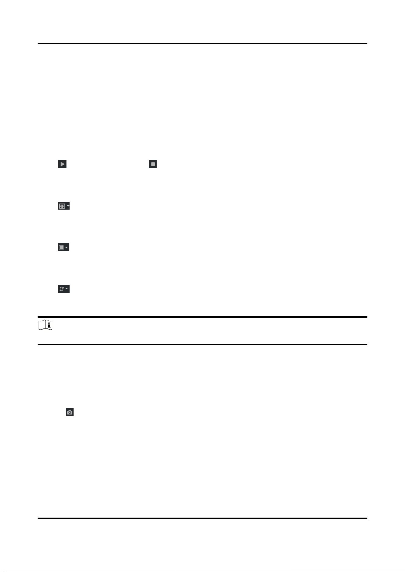
5.1.1 Start/Stop Live View
Click to start live view. Click to stop live view.
5.1.2 Select Live View Ratio
Click to select live view ratio.
5.1.3 Select Window Division Mode
Click to select a window division mode.
5.1.4 Select Stream Type
Click to select the stream type. It is recommended to select the main stream to get the high-
quality image when the network condition is good, and select the sub-stream to get the fluent
image when the network condition is not good enough. The third stream is custom.
Note
The third stream varies with different models. The actual device prevails.
5.1.5 Capture Picture Manually
You can capture pictures manually on the live view image and save them to the computer.
Steps
1. Click to capture a picture.
2. Optional: Click Configuration → Local → Live View Parameters and select Image Format.
3. Optional: Click Configuration → Local → Picture and Clip Settings to view the saving path of
snapshots in live view.

Tyre and Axle Recognition Unit User Manual
17
5.1.6 Record Manually
You can record videos manually on the live view image and save them to the computer.
Steps
1. Click to start live view.
2. Click to start recording.
3. Click to stop recording.
4. Optional: Click Configuration → Local → Record File Settings to view the saving path of record
files.
5.1.7 Enable Digital Zoom
You can enable digital zoom to zoom in a certain part of the live view image.
Steps
1. Click to start live view.
2. Click to enable digital zoom.
3. Place the cursor on the live view image position which needs to be zoomed in. Drag the mouse
rightwards and downwards to draw an area.
The area will be zoomed in.
4. Click any position of the image to restore to normal image.
5. Click to disable digital zoom.
5.1.8 Select Video Mode
Set the video mode when adjusting the device focus during construction.
Click and select when the device is running normally.
5.1.9 Enable Full Screen
Click to enable full screen mode.
5.1.10 BLC
Enable regional exposure to expose partial area of the live view image.
Steps
1. Go to Configuration → Video →Video Encoding → BLC.
2. Select a channel.
3. Check Enable.
Tyre and Axle Recognition Unit User Manual
18
4. Drag the mouse to draw an area.
5. Click Save.
Result
The drawn area will be exposed.
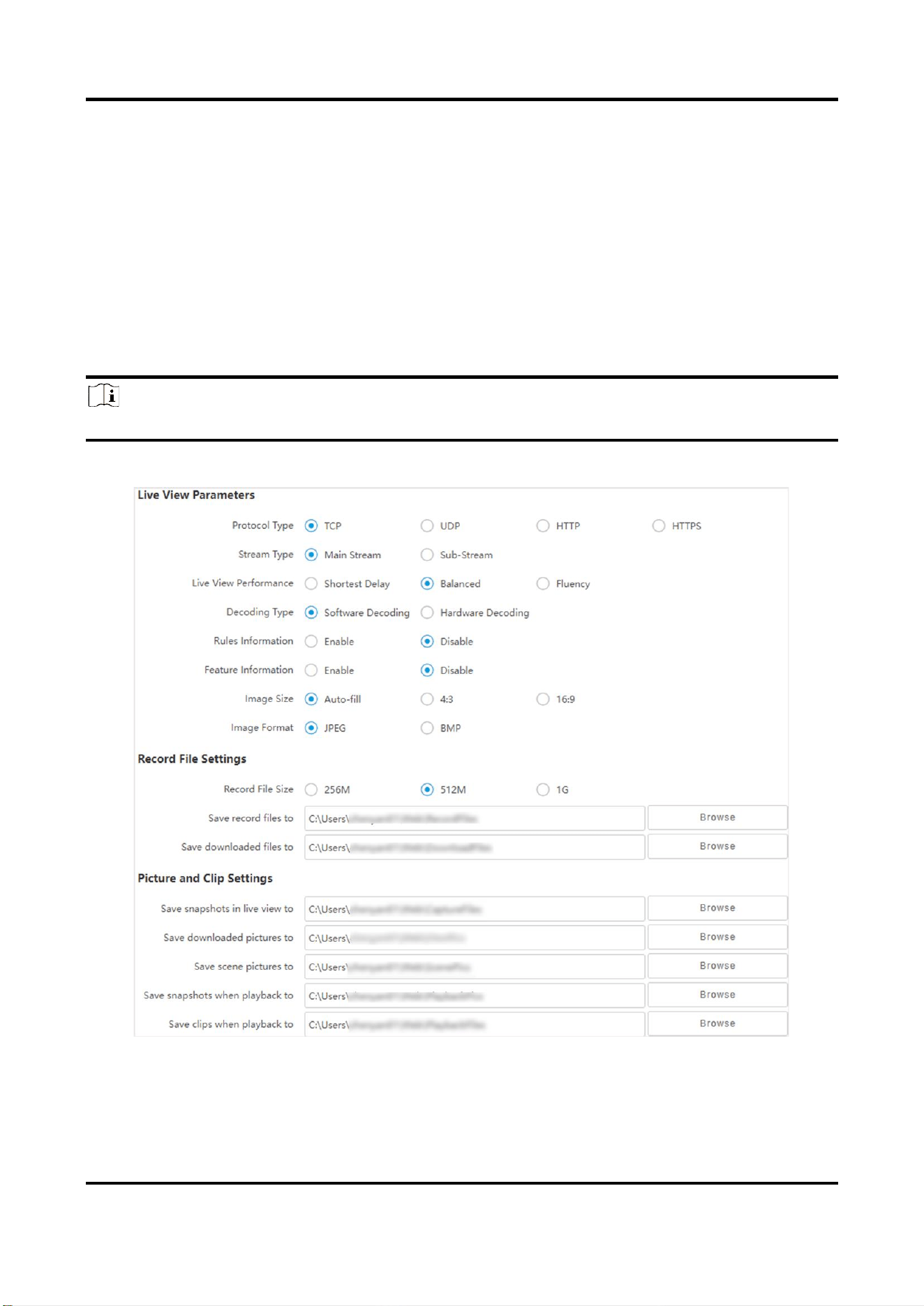
5.2 Local Configuration
Go to Configuration → Local to set the live view parameters and change the saving paths of
videos, captured pictures, scene pictures, etc.
Note
The parameters vary with different models. The actual device prevails.
Figure 5-1 Local Configuration
Protocol Type

Tyre and Axle Recognition Unit User Manual
19
Select the network transmission protocol according to the actual needs.
TCP
Ensures complete delivery of streaming data and better video quality, yet the real-time
transmission will be affected.
UDP
Provides real-time audio and video streams.
HTTP
Gets streams from the device by a third party client.
HTTPS
Gets streams in https format.
Stream Type
Main Stream
Select it to get the high-quality image when the network condition is good.
Sub-Stream
Select it to get the fluent image when the network condition is not good enough.
Live View Performance
Shortest Delay
The video is real-time, but its fluency may be affected.
Balanced
Balanced mode considers both the real time and fluency of the video.
Fluency
When the network condition is good, the video is fluent.
Decoding Type
Software Decoding
Decode via software. It takes up more CPU resources but provides images with better quality
when it compares to the hardware decoding.
Hardware Decoding
Decode via GPU. It takes up less CPU resources but provides images with worse quality when
it compares to the software decoding.
Rules Information
If you enable the rule information, tracking frames will be displayed on the live view interface
when there are vehicles passing.
Feature Information
Enable it to display feature information of the target in the live view image.

Tyre and Axle Recognition Unit User Manual
20
Image Size
The display ratio of live view.
Image Format
The saving format of manually captured images.
Record File Size
Select the packed size of the manually recorded video files. After the selection, the max. record
file size is the value you selected.
Save record files to
Set the saving path for the manually recorded video files.
Save downloaded files to
Set the saving path for the download files.
Save snapshots in live view to
Set the saving path for the manually captured pictures in live view mode.
Save downloaded pictures to
Set the saving path for the downloaded pictures.
Save scene picture to
Set the saving path of the captured pictures in Live View → Real-Time Capture.
Save snapshots when playback to
Set the saving path for the manually captured pictures in playback mode.
Save clips when playback to
Set the saving path for the clips.

Tyre and Axle Recognition Unit User Manual
21
Chapter 6 Playback
You can search, play back, and download videos that stored on the storage card.
Steps
1. Click Playback.
2. Select a channel.
3. Select a date.
4. Click Search.
5. Click to start playback.
6. Optional: You can also do the following operations.
Set playback time
●
Drag the time bar to the target time and click to play the video.
●
Click the current time point showed above the time bar and enter
the target time point in the popup window. Click OK and click
to play the video.
Capture image
Click to capture an image.
Clip record
Click / to start/stop clipping the record.
Play back in single
frame
Click once to play back the video in one frame.
Download record
1.
Click .
2.
Select the start time and end time.
3.
Click Search.
4.
Check record files that need to be downloaded.
5.
Click Download.
Stop playback
Click to stop playback.
Slow forward
Click to slow down the playback.
Fast forward
Click to speed up the playback.
Digital zoom
Click to enable digital zoom.
Click to disable digital zoom.
Zoom In
Click to zoom in images.
Zoom out
Click to zoom out images.
Tyre and Axle Recognition Unit User Manual
22
Chapter 7 Record and Capture
7.1 Set Storage Path
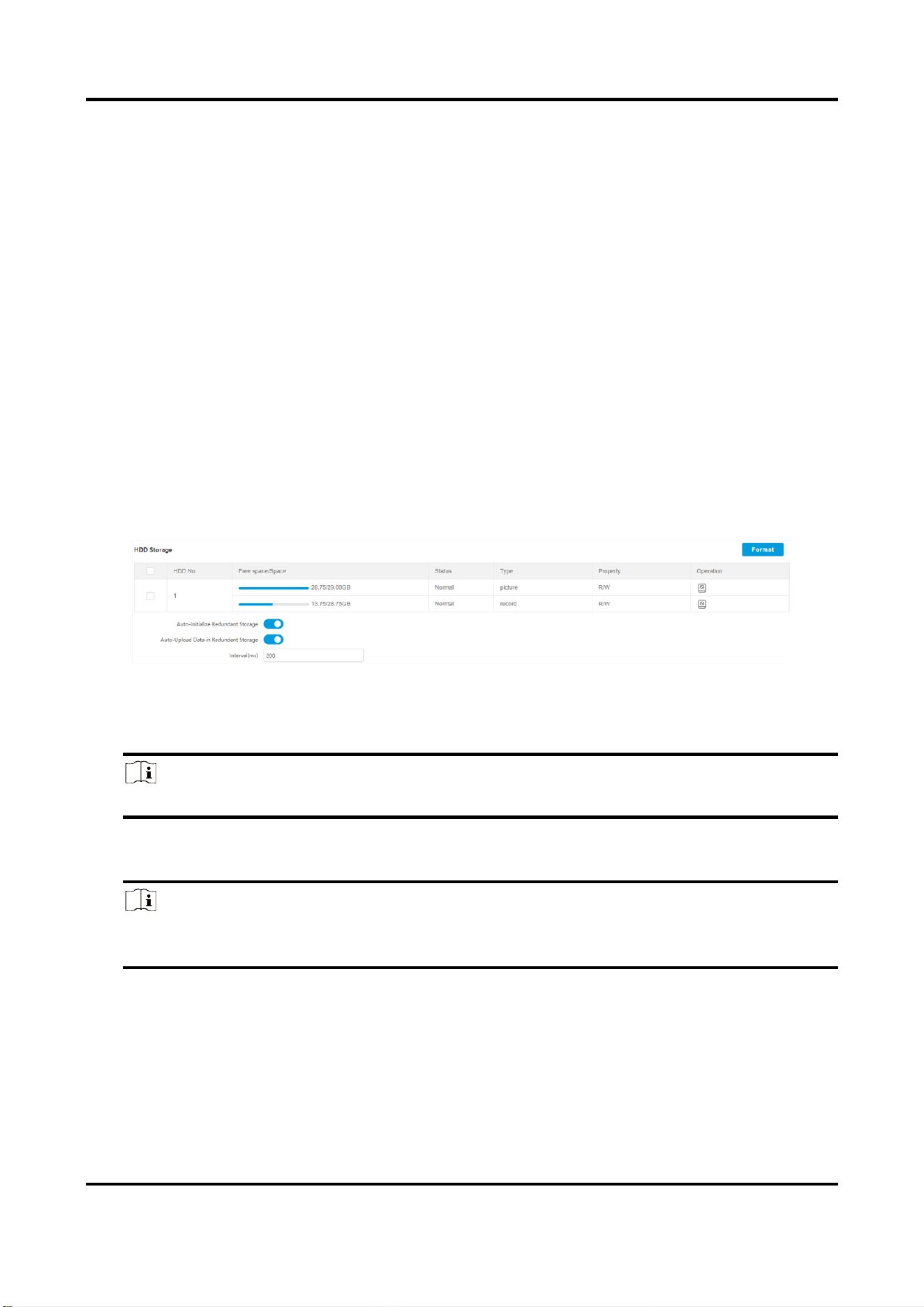
7.1.1 Set Storage Card
If you want to store the files to the storage card, make sure you insert and format the storage card
in advance.
Before You Start
Insert the storage card to the device.
Steps
1. Go to Configuration → Storage → Storage Management → HDD Management → HDD Storage.
Figure 7-1 Set Storage Card
2. Format the storage card in two ways.
–
Check the storage card, and click Format to format it manually.
Note
For the newly installed storage card, you need to format it manually before using it normally.
–
If you want to format the storage card automatically when the card is abnormal, enable Auto-
Initialize Redundant Storage.
Note
If you enable Auto-Initialize Redundant Storage, reboot the device to take the settings into
effect.
3. Optional: If the device has been connected to the platform, and you want to upload the storage
card information automatically, enable Auto-Upload Data in Redundant Storage.
4. Set Interval.
4. Click Save.
Tyre and Axle Recognition Unit User Manual
23
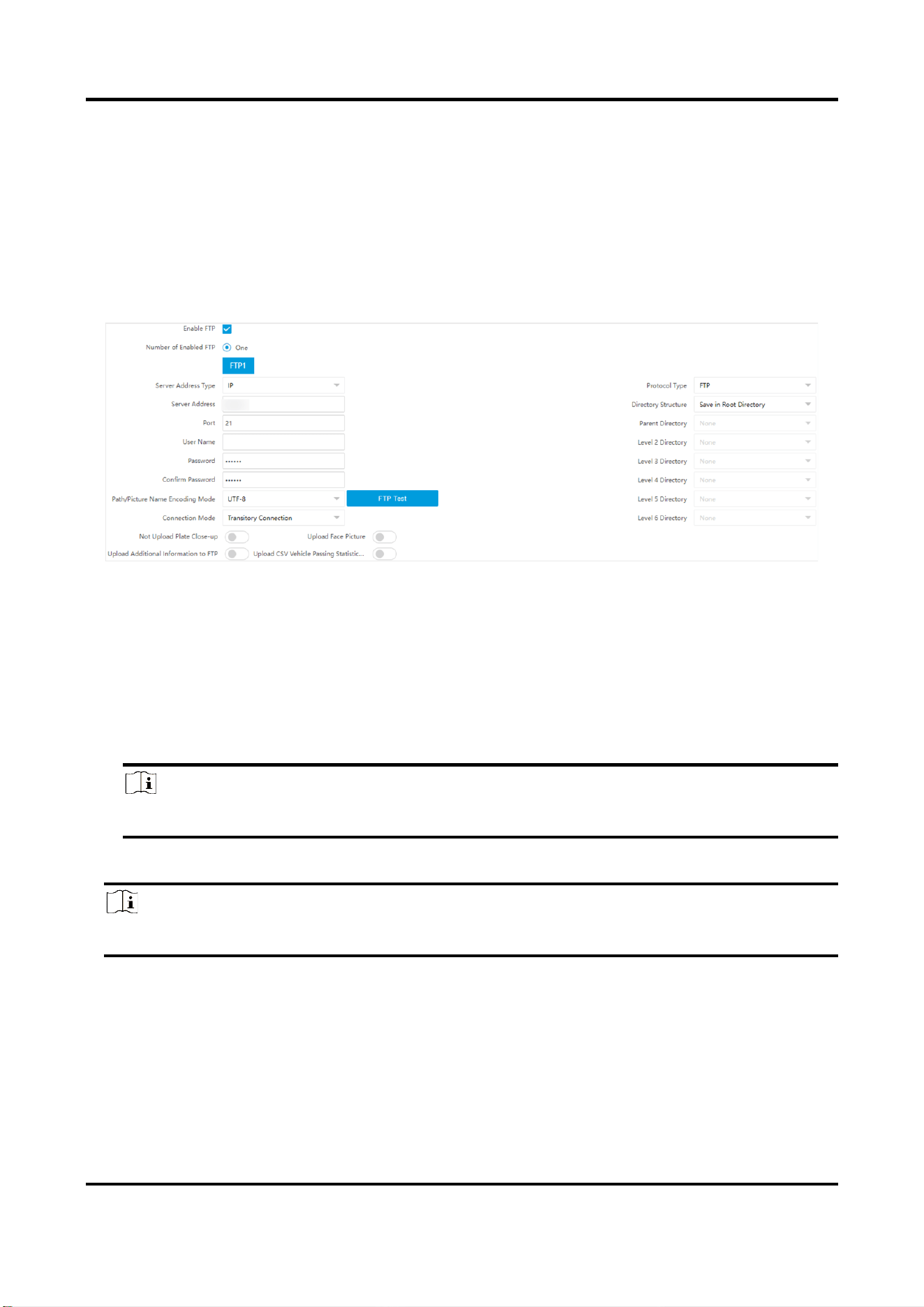
7.1.2 Set FTP
Set FTP parameters if you want to upload the captured pictures to the FTP server.
Before You Start
Set the FTP server, and ensure the device can communicate normally with the server.
Steps
1. Go to Configuration → Network → Data Connection → FTP.
Figure 7-2 Set FTP
2. Check Enable FTP.
3. Set FTP Parameters.
1) Select Sever Address Type and enter corresponding information.
2) Enter Port.
3) Enter User Name, Password, and confirm the password.
4) Select Protocol Type.
5) Select Directory Structure and Connection Mode.
Note
You can customize the directory structure according to your needs.
4. Optional: Enable upload functions.
Note
Supported functions vary with different models. The actual device prevails.
Not Upload Plate Close-up
The close-up pictures of a license plate will not be uploaded.
Upload Additional Information to FTP
Add related information when uploading data to the FTP server.
Upload CSV Vehicle Passing Statistics Information to FTP
Tyre and Axle Recognition Unit User Manual
24
The CSV Vehicle Passing Statistics Information will be uploaded to FTP server.
Upload Face Picture
Face pictures will be uploaded to FTP server.
5. Optional: Click FTP Test to check the FTP server.
6. Set naming rules and separators according to the actual needs.
7. Optional: Edit OSD information which can be uploaded to the FTP server with the pictures to
make it convenient to view and distinguish the data.
8. Click Save.
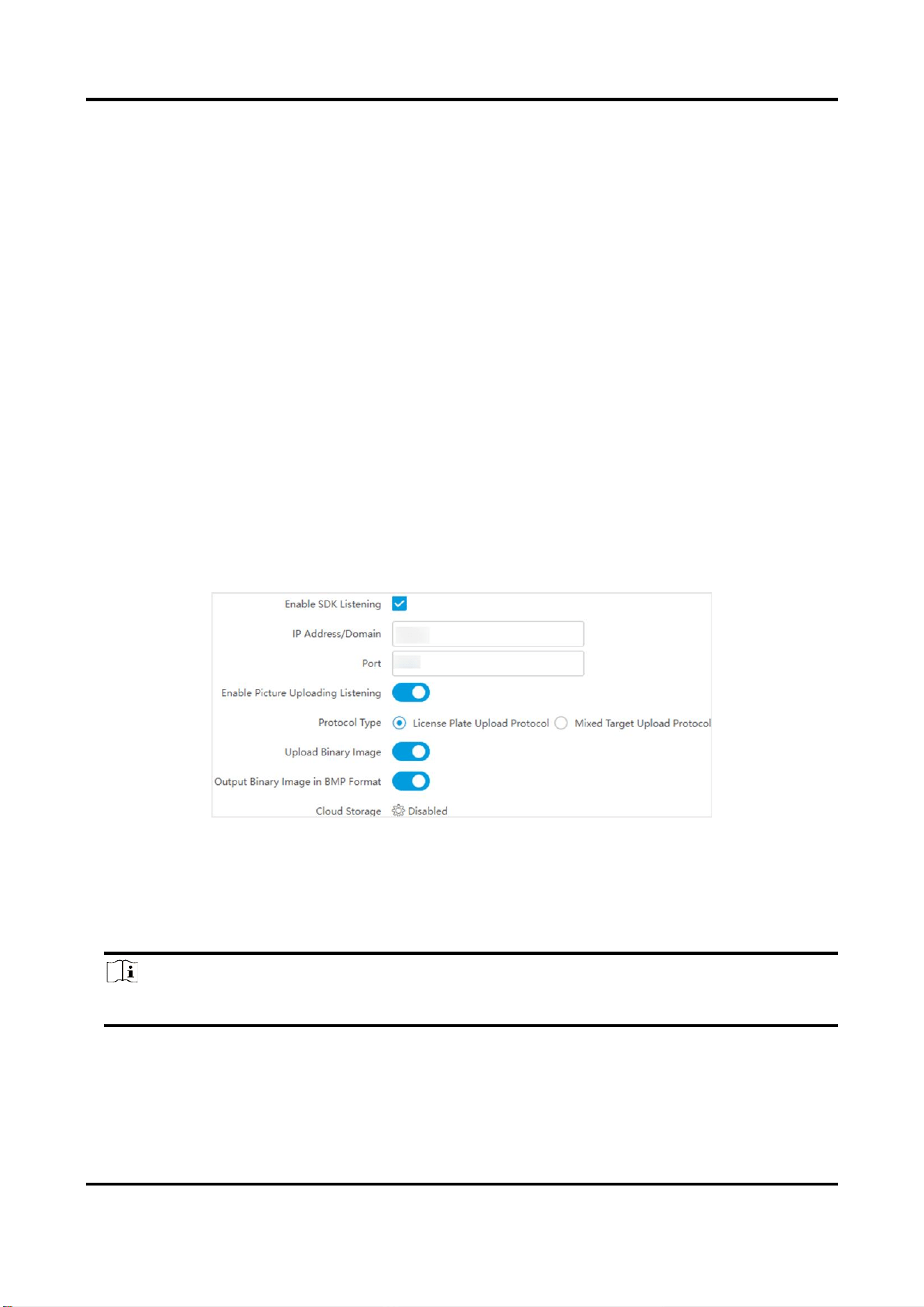
7.1.3 Set SDK Listening
The SDK listening can be used to receive the uploaded information and pictures of the device
arming alarm.
Before You Start
The listening service has been enabled for the SDK listening, and the network communication with
the device is normal.
Steps
1. Go to Configuration → Network → Data Connection → SDK Listening.
Figure 7-3 Set SDK Listening
2. Check Enable SDK Listening.
3. Set IP Address/Domain and Port if you need to upload the alarm information and pictures.
4. Optional: Enable Enable Picture Uploading Listening if you need to upload image information.
5. Select Protocol Type.
Note
Supported functions vary with different models. The actual device prevails.
License Plate Upload Protocol
Uploads arming alarm images of the license plate. You can enable Upload Binary Image if you
need to upload images which are full of black or white pixel points. Enable Output Binary
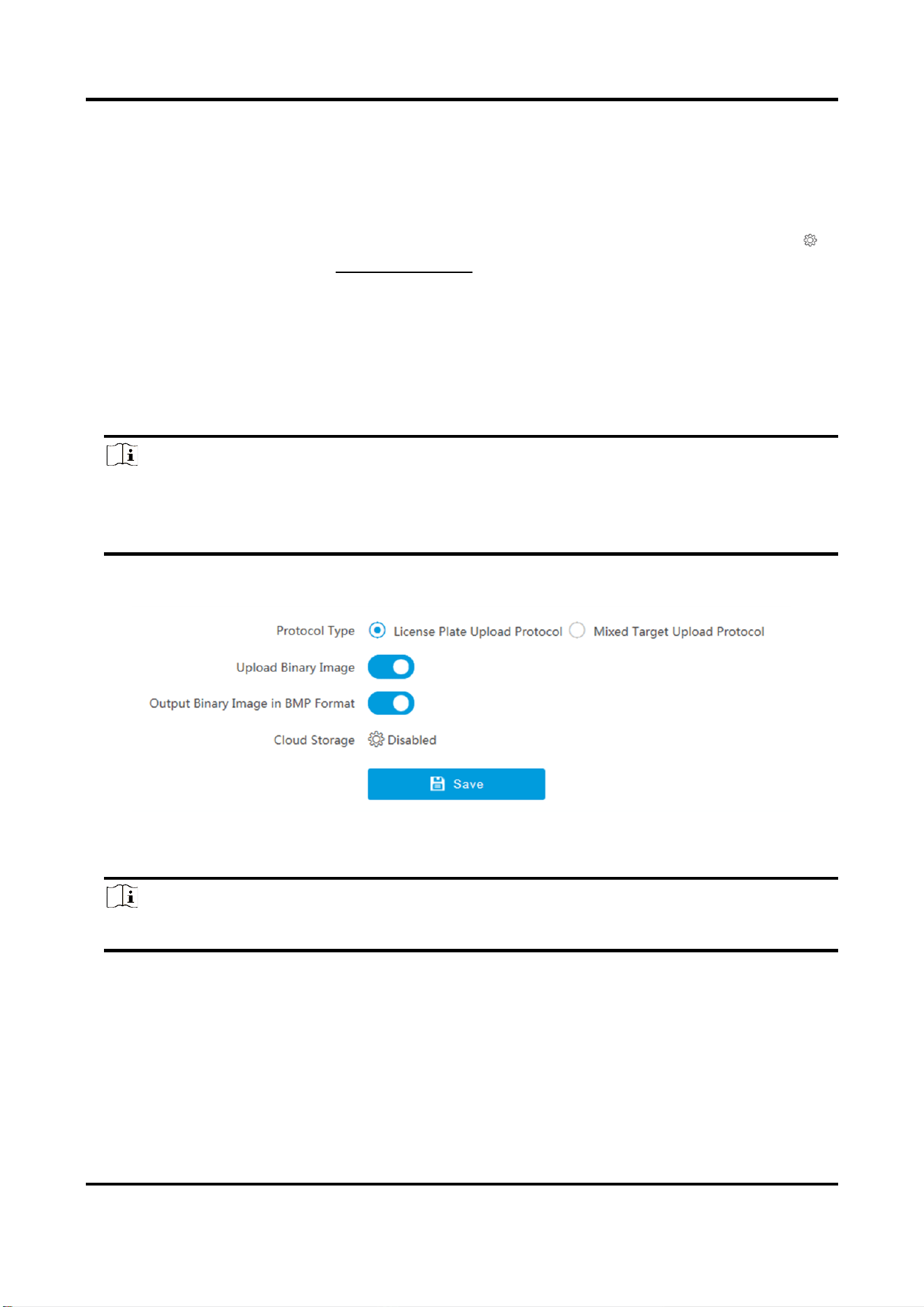
Tyre and Axle Recognition Unit User Manual
25
Image in BMP Format if you want to output images in this format.
Mixed Target Upload Protocol
Uploads images of multiple targets such as humans and vehicles. You can enable the body
property to recognize clothes, bags, and other properties.
5. Optional: If you want to save the alarm information and pictures to the cloud storage, click
to set Cloud Storage. Refer to Set Cloud Storage for details.
6. Click Save.
7.1.4 Set Arm Host
The device can upload the captured pictures via the arm host.
Steps
Note
For level 1 arm, the pictures can be uploaded normally. If uploading failed, the device will
upload again. For level 2 arm, the pictures will be uploaded once. No more upload if uploading
failed. For level 3 arm, pictures will not be uploaded.
1. Go to Configuration → Network → Data Connection → Arm Upload.
Figure 7-4 Set Arm Host
2. Select Protocol Type.
Note
Supported functions vary with different models. The actual device prevails.
License Plate Upload Protocol
Uploads arming alarm images of the license plate. You can enable Upload Binary Image if you
need to upload binary images full of black or white pixel points. Enable Output Binary Image
in BMP Format if you want to output images in this format.
Mixed Target Upload Protocol
Tyre and Axle Recognition Unit User Manual
26
Uploads images of multiple targets such as humans and vehicles. You can enable the body
property to recognize clothes, bags, and other properties.
3. Optional: If you want to save the alarm information and pictures to the cloud storage, click
to set Cloud Storage. Refer to Set Cloud Storage for details.
4. Click Save.
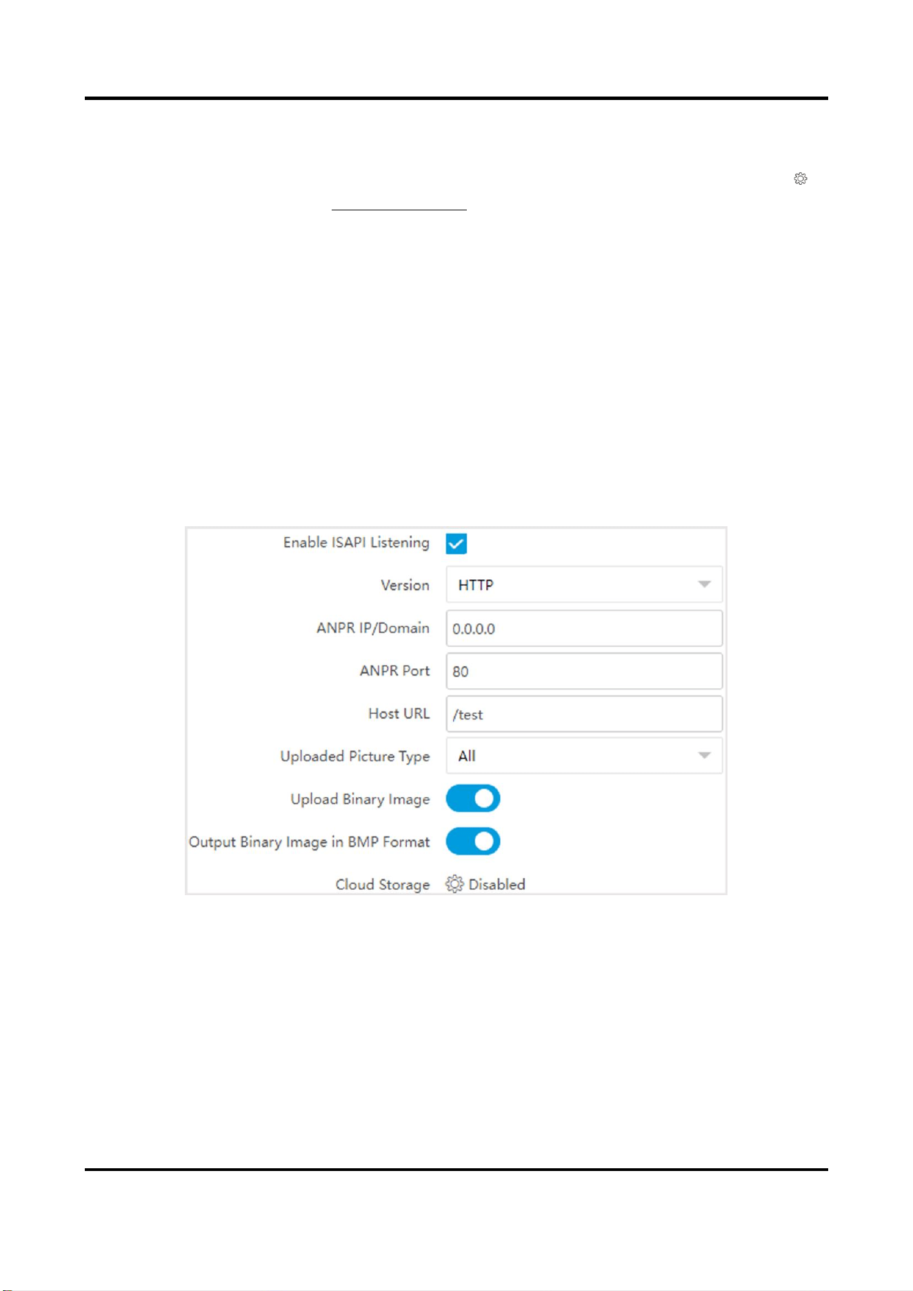
7.1.5 Set ISAPI Listening
ISAPI listening and SDK listening are mutually exclusive protocols. If you enable the picture
uploading listening, the device will transmit images via the SDK listening. If not, the device will
upload images via ISAPI protocol after the ISAPI parameters are set.
Before You Start
The listening service has been enabled for the ISAPI host, and the network communication with
the device is normal.
Steps
1. Go to Configuration → Network → Data Connection → ISAPI Listen.
Figure 7-5 Set ISAPI Listening
2. Check Enable ISAPI Listening.
3. Set ANPR IP/Domain, ANPR Port, and Host URL.
4. Select Uploaded Picture Type.
5. Optional: Enable Upload Binary Image if you need to upload images which are full of black or
white pixel points.
Tyre and Axle Recognition Unit User Manual
27
Note
Enable Output Binary Image in BMP Format if you want to output images in this format.
6. Optional: If you want to save the alarm information and pictures to the cloud storage, click
to set Cloud Storage. Refer to Set Cloud Storage for details.
7. Click Save.
7.1.6 Set Cloud Storage
Cloud storage is a kind of network storage. It can be used as the extended storage to save the
captured pictures.
Before You Start
●
Arrange the cloud storage server.
●
You have enabled level 1 arming in Live View → Real-Time Capture.
Note
The real-time capture should be used with dedicated platform.
Steps
1. Go to Configuration → Storage → Storage Management → Cloud Storage.
Figure 7-6 Set Cloud Storage
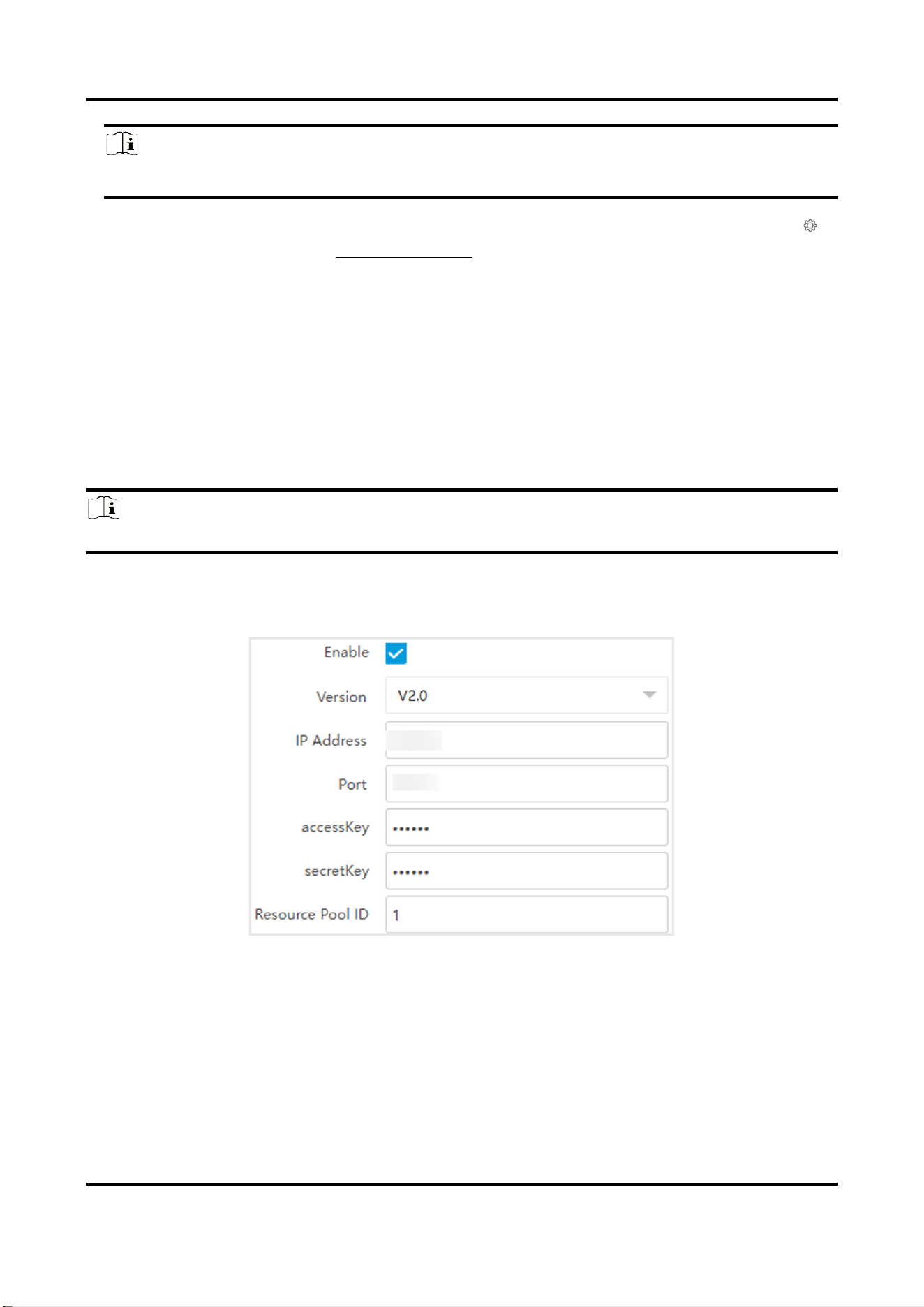
2. Check Enable.
3. Select Version.
V1.0
1.
Enter IP Address and Port
2.
Enter User Name and Password.
3.
Enter Cloud Storage ID and Violation Cloud Storage ID according
to the server storage area No.
Tyre and Axle Recognition Unit User Manual
28
V2.0
1.
Enter IP Address and Port.
2.
Enter accessKey and secretKey.
3.
Enter Resource Pool ID according to the server storage area No.
of uploading pictures.
4. Click Save.
7.2 Set Quota
Set the video and picture ratio in the storage.
Before You Start
Install the storage card.
Steps
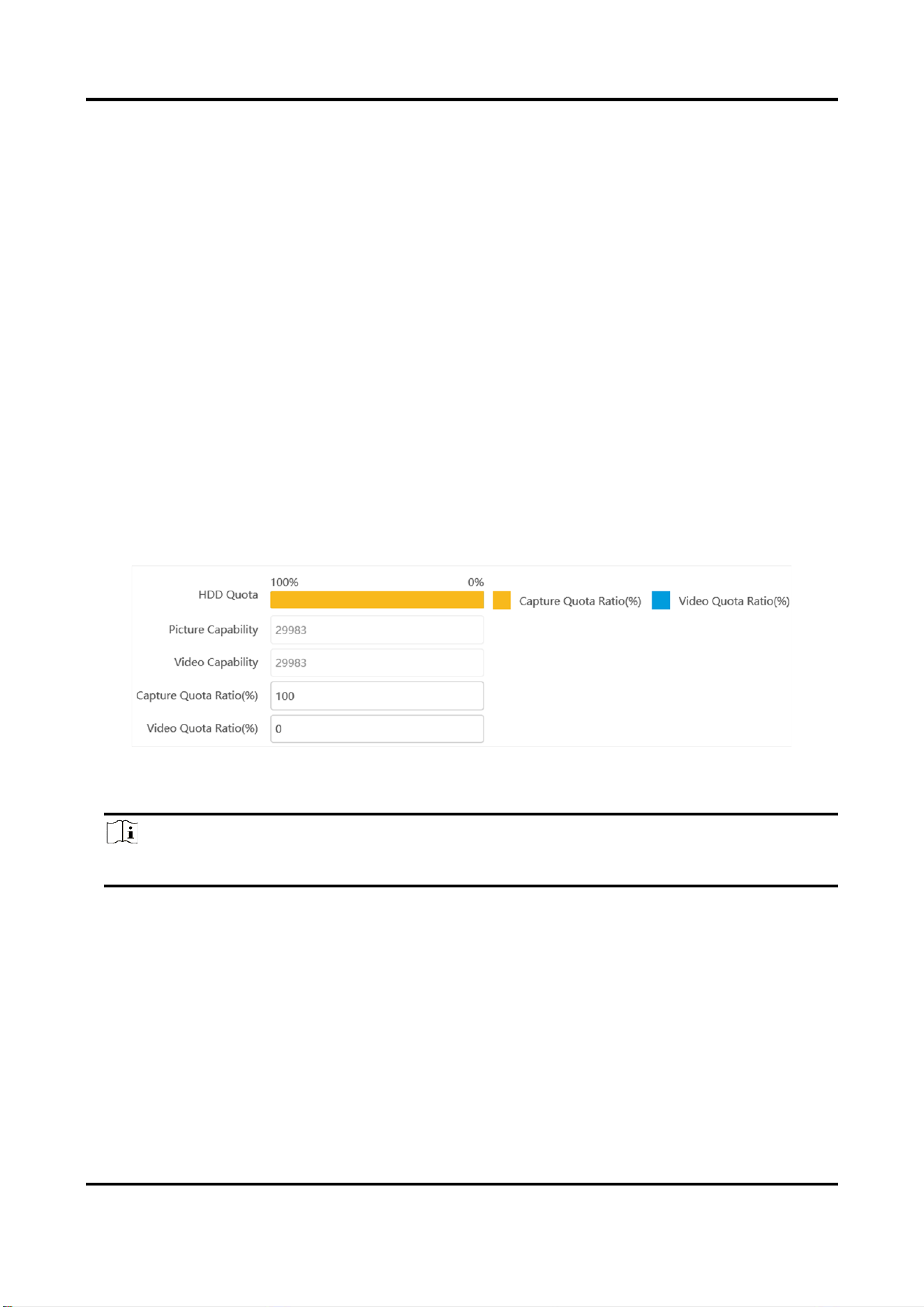
1. Go to Configuration → Storage → Storage Management → HDD Quota.
Figure 7-7 Set Quota
2. Set Capture Quota Ratio and Video Quota Ratio according to the actual needs.
Note
The percentage sum of the capture and video quota ratio should be 100 %.
3. Click Save.
What to do next
Format the storage card after the settings.
Tyre and Axle Recognition Unit User Manual
29
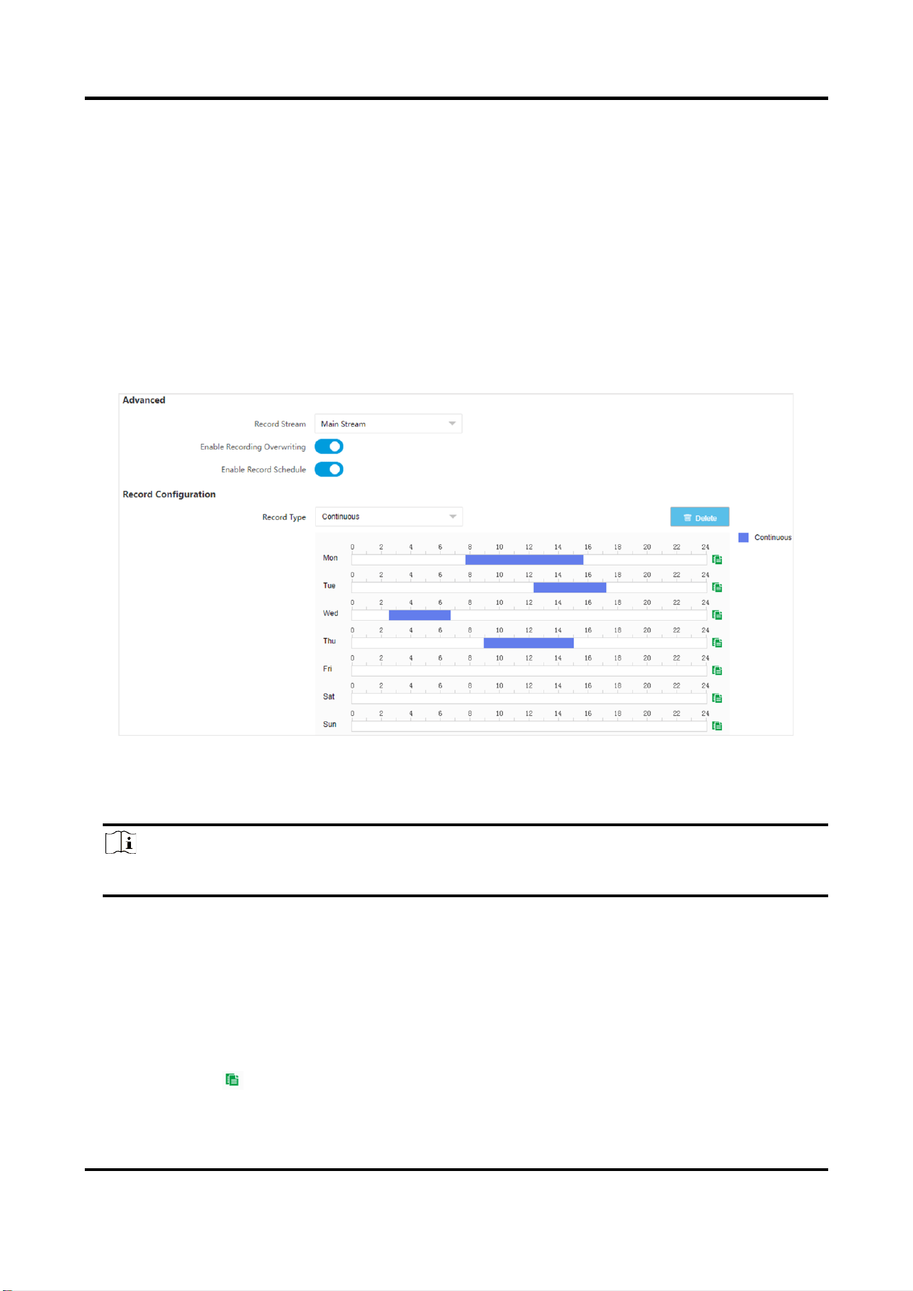
7.3 Set Record Schedule
Set record schedule to record video automatically during configured time periods.
Before You Start
Install the storage card.
Steps
1. Go to Configuration → Storage → Schedule Settings → Record Schedule.
2. Optional: Enable the recording overwriting.
When the storage is full, the earliest videos will be overwritten.
3. Enable the record schedule.
Figure 7-8 Set Record Schedule
4. Select Record Type.
5. Drag the cursor on the time bar to set a recording time.
Note
Up to 8 time periods can be set on a time bar.
6. Adjust the recording time.
–
Click a set recording period and enter the start time and end time in the pop-up window.
–
Drag two ends of the set recording period bar to adjust the length.
–
Drag the whole set recording period bar and relocate it.
7. Optional: Delete recording periods.
–
Click a set recording period and click Delete in the pop-up window.
–
Click a set recording period and click Delete on the record configuration interface.
8. Optional: Click to copy set recordings to other days.
9. Click Save.

Tyre and Axle Recognition Unit User Manual
30
Result
The device will only record at the set periods.

Tyre and Axle Recognition Unit User Manual
31
Chapter 8 Encoding and Display
8.1 Set Video Encoding Parameters
Set video encoding parameters to adjust the live view and recording effect.
●
When the network signal is good and the speed is fast, you can set high resolution and bitrate to
raise the image quality.
●
When the network signal is bad and the speed is slow, you can set low resolution, bitrate, and
frame rate to guarantee the image fluency.
●
When the network signal is bad, but the resolution should be guaranteed, you can set low
bitrate and frame rate to guarantee the image fluency.
●
Main stream stands for the best stream performance the device supports. It usually offers the
best resolution and frame rate the device can do. But high resolution and frame rate usually
means larger storage space and higher bandwidth requirements in transmission. Sub-stream
usually offers comparatively low resolution options, which consumes less bandwidth and
storage space. Third stream is offered for customized usage.
Steps
Note
The supported parameters vary with different models. The actual device prevails.
1. Go to Configuration → Video → Video Encoding → Video Encoding.
2. Set the parameters for different streams.
Stream Type
Select the stream type according to your needs.
Note
The supported stream types vary with different models. The actual device prevails.
Bitrate
Select relatively large bitrate if you need good image quality and effect, but more storage
spaces will be consumed. Select relatively small bitrate if storage requirement is in priority.
Frame Rate
It is to describe the frequency at which the video stream is updated and it is measured by
frames per second (fps). A higher frame rate is advantageous when there is movement in the
video stream, as it maintains image quality throughout.
Resolution
The higher the resolution is, the clearer the image will be. Meanwhile, the network

Tyre and Axle Recognition Unit User Manual
32
bandwidth requirement is higher.
SVC
Scalable Video Coding (SVC) is an extension of the H.264/AVC and H.265 standard. Enable the
function and the device will automatically extract frames from the original video when the
network bandwidth is insufficient.
Bitrate Type
Select the bitrate type to constant or variable.
Video Quality
When bitrate type is variable, 6 levels of video quality are selectable. The higher the video
quality is, the higher requirements of the network bandwidth.
Profile
When you select H.264 or H.265 as video encoding, you can set the profile. Selectable profiles
vary according to device models.
I Frame Interval
It refers to the number of frames between two key frames. The larger the I frame interval is,
the smaller the stream fluctuation is, but the image quality is not that good.
Video Encoding
The device supports multiple video encoding types, such as H.264, H.265, and MJPEG.
Supported encoding types for different stream types may differ. H.265 is a new encoding
technology. Compared with H.264, it reduces the transmission bitrate under the same
resolution, frame rate, and image quality.
3. Click Save.
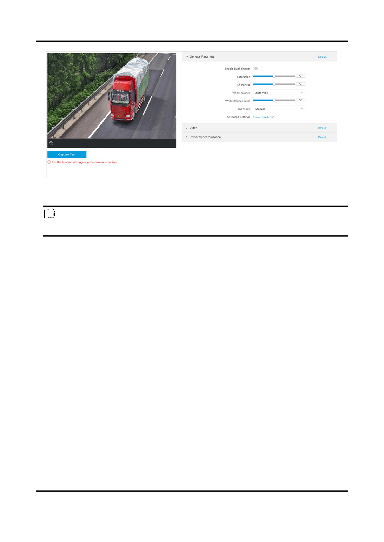
8.2 Set Image Parameters
You can adjust the image parameters to get clear image.
Steps
Note
The supported parameters may vary with different models. The actual device prevails.
1. Go to Configuration → Video → Camera Parameter → Camera Parameter.
Tyre and Axle Recognition Unit User Manual
33
Figure 8-1 Set Image Parameters
2. Set the camera parameters.
Note
The supported parameters vary with different models. The actual device prevails.
General Parameter
Enable Dual-Shutter
Set Stream Type after enabling it.
Saturation
It refers to the colorfulness of the image color.
Sharpness
It refers to the edge contrast of the image.
White Balance
It is the white rendition function of the device used to adjust the color temperature
according to the environment.
Brightness Enhancement at Night
The scene brightness will be enhanced at night automatically.
Enable Gamma Correction
The higher the gamma correction value is, the stronger the correction strength is.
Video
Brightness
It refers to the brightness the image.
Contrast

Tyre and Axle Recognition Unit User Manual
34
It refers to the contrast of the image. Set it to adjust the levels and permeability of the
image.
Shutter
If the shutter speed is quick, the details of the moving objects can be displayed better. If
the shutter speed is slow, the outline of the moving objects will be fuzzy and trailing will
appear.
Gain
It refers to the upper limit value of limiting image signal amplification. It is recommended
to set a high gain if the illumination is not enough, and set a low gain if the illumination is
enough.
Hue Range
Select the range to adapt to the display.
3D DNR
Digital Noise Reduction (DNR) reduces the noise in the video stream.
In Normal Mode, the higher the 3D DNR Level is, the stronger the noise will be reduced.
But if it is too high, the image may become fuzzy.
In Expert Mode, set Spatial Intensity and Time Intensity. If the space domain intensity is
too high, the outline of the image may become fuzzy and the details may lose. If the time
domain intensity is too high, trailing may appear.
2D DNR
The higher the 2D DNR Level is, the stronger the noise will be reduced. But if it is too high,
the image may become fuzzy.
Video Standard
Select the video standard according to the actual power supply frequency.
Power Synchronization
Power Synchronization
The street lights and traffic lights will cause image flashing in live view. Check it, and set
Phase Position and Signal Frequency to overcome the image flashing in live view.
3. Optional: Click Capture Test to check the image.
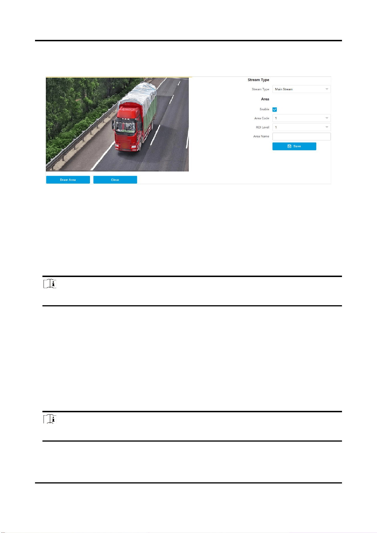
8.3 Set ROI
ROI (Region of Interest) encoding helps to assign more encoding resources to the region of
interest, thus to increase the quality of the ROI whereas the background information is less
focused.
Before You Start
Please check the video encoding type. ROI is supported when the video encoding type is H.264 or
H.265.
Tyre and Axle Recognition Unit User Manual
35
Steps
1. Go to Configuration → Video → Video Encoding → ROI.
Figure 8-2 Set ROI
2. Select Stream Type.
3. Set ROI region.
1) Check Enable.
2) Select Area Code.
3) Click Draw Area.
4) Drag the mouse on the live view image to draw a fixed area.
5) Select the fixed area that needs to be adjusted and drag the mouse to adjust its position.
4. Select ROI Level and enter Area Name.
Note
The higher the ROI level is, the clearer the image of the detected area is.
5. Click Save.
6. Optional: Select other area codes and repeat the steps above if you need to draw multiple fixed
areas.
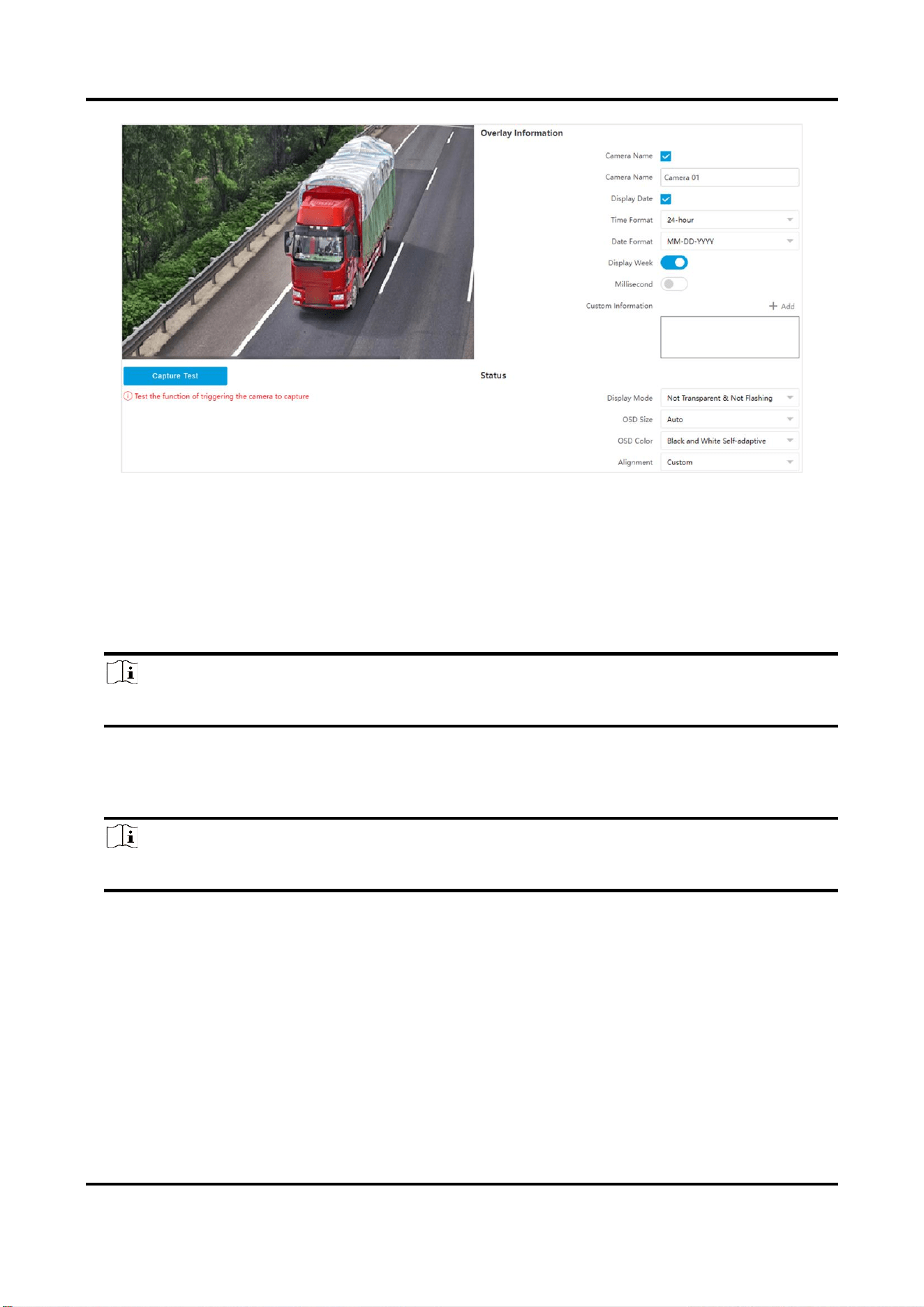
8.4 Set OSD
You can customize OSD information on the live view.
Steps
1. Go to Configuration → Video → Text Overlay on Video → Text Overlay on Video.
Note
The supported functions vary with different models. The actual device prevails.
Tyre and Axle Recognition Unit User Manual
36
Figure 8-3 Set OSD
2. Set display contents.
1) Check Camera Name.
2) Enter Camera Name.
3) Check Display Date, and set the time and date format.
4) Enable Display Week or Millisecond according to your needs.
3. Optional: Click Add and enter information if you want to add custom information.
Note
Up to 6 items of custom information can be added.
4. Set Display Mode according to actual needs.
5. Set display properties (font, color, etc.).
6. Select Alignment.
Note
If you select Align Left or Align Right, set Min. Horizontal Margin and Min. Vertical Margin.
7. Drag the red frames on the live view image to adjust their positions.
8. Click Save.
Result
The set OSD will be displayed in live view image and recorded videos.
8.5 Set Privacy Mask
The privacy mask can be used to protect personal privacy by concealing parts of the image from

Tyre and Axle Recognition Unit User Manual
37
view or recording with a masked area.
Steps
1. Go to Configuration → Video → Video Encoding → Privacy Mask.
2. Check Enable Privacy Mask.
3. Enable the privacy mask area(s).
1) Check Enable.
2) Select Area Code.
3) Select Type.
4. Draw the privacy mask area.
1) Click Draw Area.
2) In the live view image, drag the mouse to draw the privacy mask area of the selected area
code.
3) Click Stop Drawing.
4) Optional: Click Clear to clear all the drawn areas.
5. Optional: Repeat step 3 and 4 to draw more privacy mask areas.
Note
Up to four privacy mask areas are supported.
6. Click Save.

Tyre and Axle Recognition Unit User Manual
38
Chapter 9 Network Configuration
9.1 Set IP Address
IP address must be properly configured before you operate the device over network. IPv4 and IPv6
are both supported. Both versions can be configured simultaneously without conflicting to each
other.
Steps
Note
The supported parameters vary with different models. The actual device prevails.
1. Go to Configuration → Network → Network Parameters → Network Interface.
Tyre and Axle Recognition Unit User Manual
39
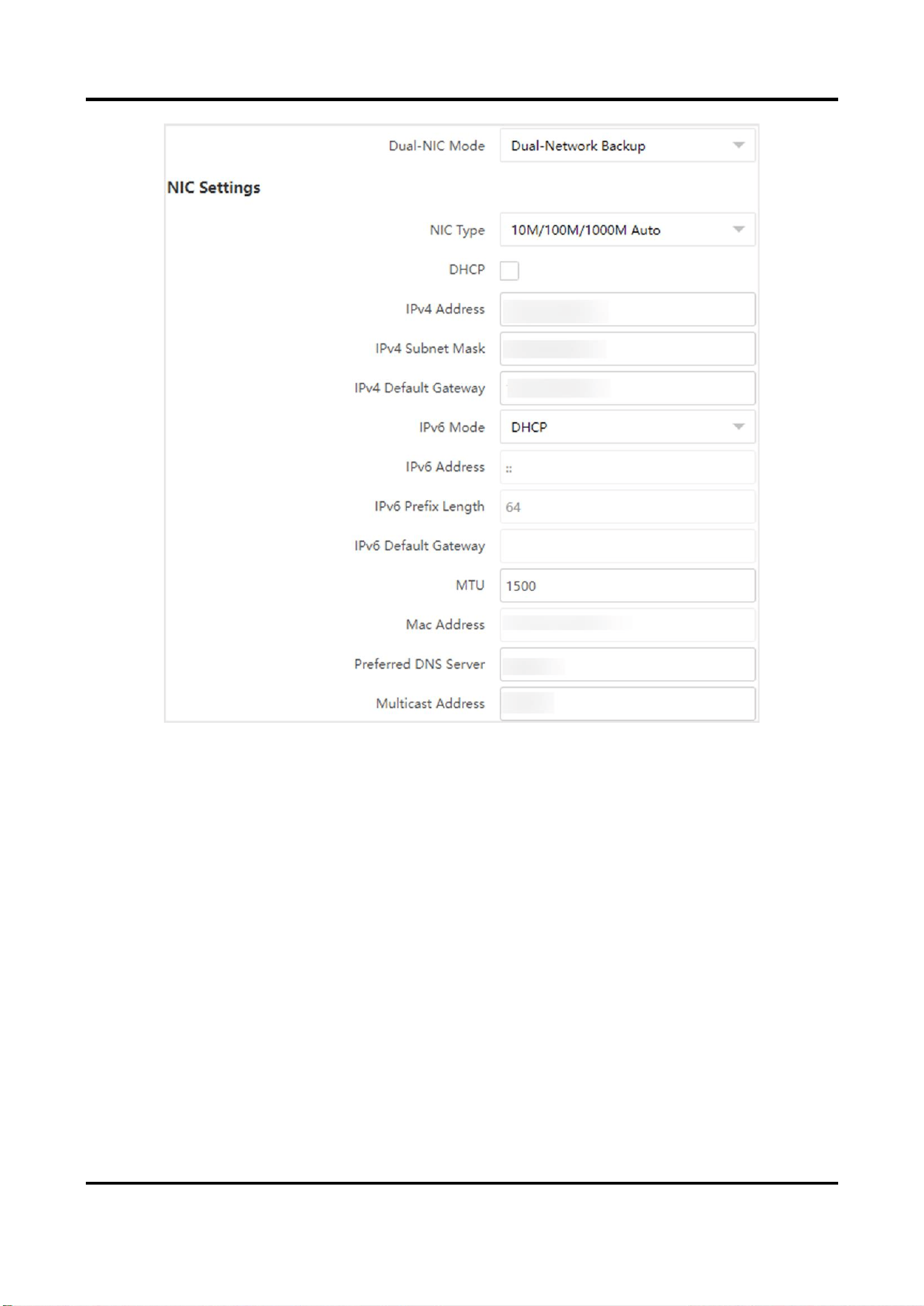
Figure 9-1 Set IP Address
2. Select Dual-NIC Mode.
Dual-Network Backup
Select it when the two network interfaces are connected to two network cables respectively.
When one network interface fails, the other network interface will be employed
automatically without influencing the data transmission.
Multi-Network Isolation
Select it when different LANs are connected. Set the IP addresses of different network
segments.
3. Set IPv4 Address, subnet mask, gateway and other network parameters.
NIC Type
Select a NIC (Network Interface Card) Type according to your network condition.
IPv6
Three IPv6 modes are available.

Tyre and Axle Recognition Unit User Manual
40
Route Advertisement
The IPv6 address is generated by combining the route advertisement and the device Mac
address.
Note
Route advertisement mode requires the support from the router that the device is
connected to.
DHCP
The IPv6 address is assigned by the server, router, or gateway.
Note
The network that the device is connected to should support DHCP (Dynamic Host
Configuration Protocol).
Manual
Enter IPv6 Address, IPv6 Subnet Mask, and IPv6 Gateway. Consult the network
administrator for required information.
MTU
It stands for maximum transmission unit. It is the size of the largest protocol data unit that
can be communicated in a single network layer transaction.
The valid value range of MTU is 1280 to 1500.
Multicast Address
Multicast is group communication where data transmission is addressed to a group of
destination devices simultaneously. After setting the IP address of the multicast host, you can
send the source data efficiently to multiple receivers.
DNS
It stands for domain name server. It is required if you need to visit the device with domain
name. And it is also required for some applications (e.g., sending email). Set Preferred DNS
Address properly if needed.
3. Click Save.
9.2 Connect to ISUP Platform
ISUP (EHome) is a platform access protocol. The device can be remotely accessed via this platform.
Before You Start
●
Create the device ID on ISUP platform.
●
Ensure the device can communicate with the platform normally.
Tyre and Axle Recognition Unit User Manual
41
Steps
1. Go to Configuration → Network → Data Connection → ISUP.
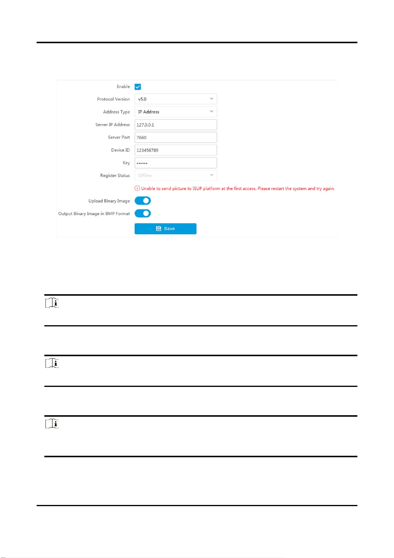
Figure 9-2 Connect to ISUP Platform
2. Check Enable.
3. Select Protocol Version.
4. Select Address Type.
5. Enter Sever IP Address, Server Port, and Device ID.
Note
You need to enter Key if you select Protocol Version as v5.0.
6. Optional: For protocol v5.0, you can enable Upload Binary Image if you need to upload images
which are full of black or white pixel points.
Note
Enable Output Binary Image in BMP Format if you want to output images in this format.
7. Click Save.
8. Optional: View Register Status.
Note
When the registration status shows online, you can add or manage the device via the platform
software. Refer to its corresponding manual for details.
Tyre and Axle Recognition Unit User Manual
42
9.3 Set DDNS
You can use the Dynamic DNS (DDNS) for network access. The dynamic IP address of the device
can be mapped to a domain name resolution server to realize the network access via domain
name.
Before You Start
●
Register the domain name on the DDNS server.
●
Set the LAN IP address, subnet mask, gateway, and DNS server parameters. Refer to "Set IP
Address" for details.
●
Complete port mapping. The default ports are 80, 8000, and 554.
Steps
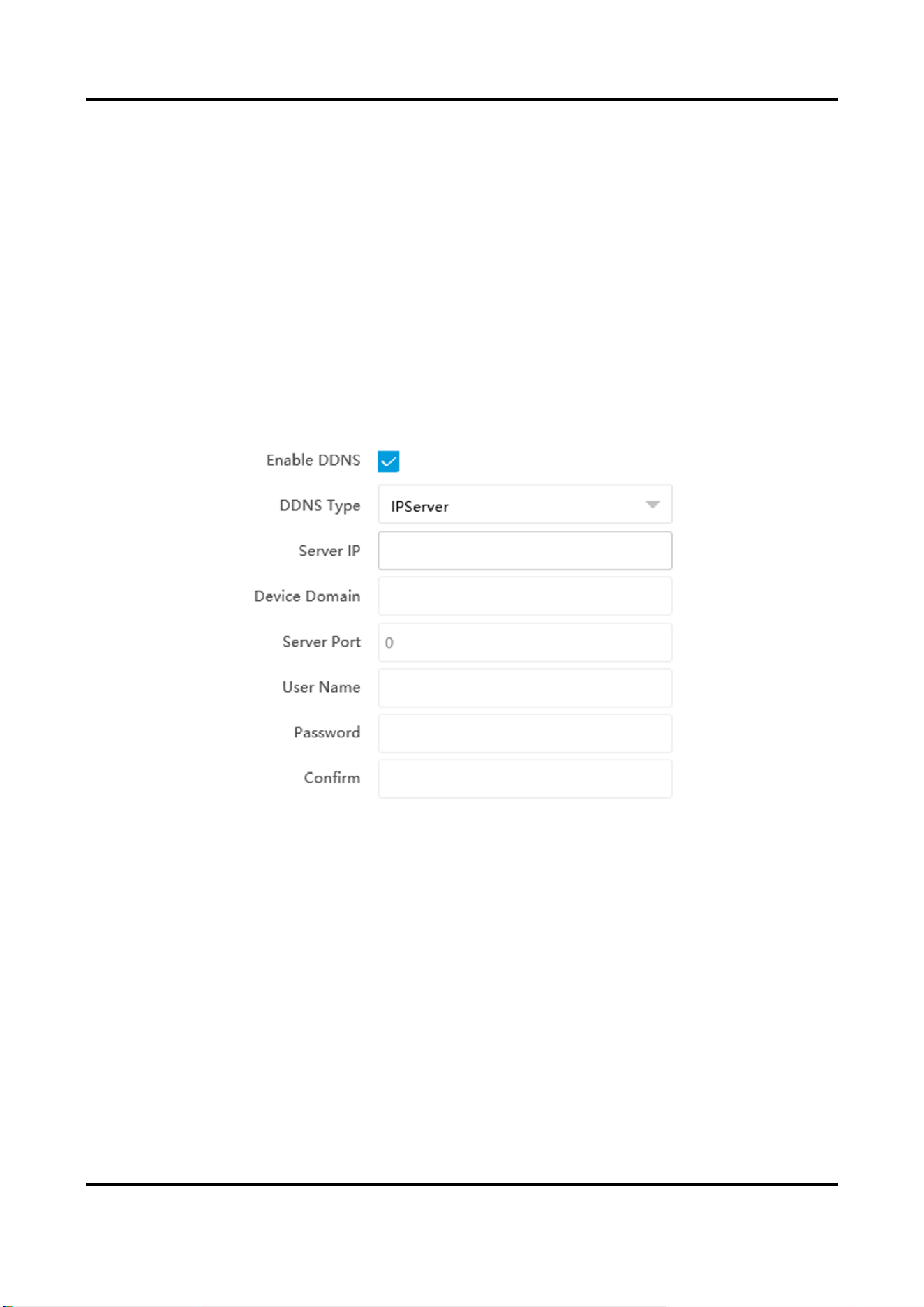
1. Go to Configuration → Network → Network Parameters → DDNS.
Figure 9-3 Set DDNS
2. Check Enable DDNS.
3. Enter the server address and other information.
4. Click Save.
5. Access the device.
By Browsers
Enter the domain name in the browser address bar to access the
device.
By Client Software
Add domain name to the client software. Refer to the client software
manual for specific adding methods.

Tyre and Axle Recognition Unit User Manual
43
9.4 Set SNMP
You can set the SNMP network management protocol to get the alarm event and exception
messages in network transmission.
Before You Start
Download the SNMP software and manage to receive the device information via SNMP port.
Steps
1. Go to Configuration → Network → Network Parameters → SNMP.
2. Check Enable SNMPv1/Enable SNMP v2c/Enable SNMPv3.
Note
●
The SNMP version you select should be the same as that of the SNMP software.
●
Use different versions according to the security levels required. SNMP v1 is not secure and
SNMP v2 requires password for access. SNMP v3 provides encryption and if you use the third
version, HTTPS protocol must be enabled.
3. Set the SNMP parameters.
4. Click Save.
9.5 Set Port
The device port can be modified when the device cannot access the network due to port conflicts.
Go to Configuration → Network → Network Parameters → Port for port settings.
Tyre and Axle Recognition Unit User Manual
44
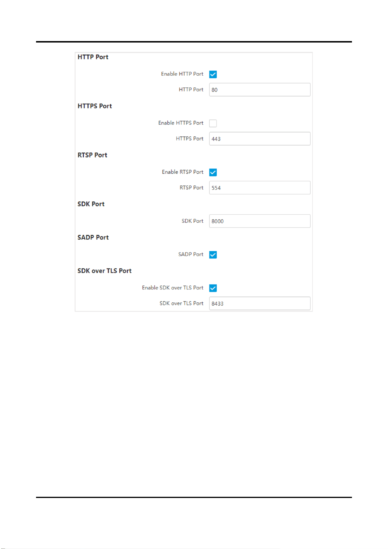
Figure 9-4 Set Port
HTTP Port
It refers to the port through which the browser accesses the device. For example, when the
HTTP Port is modified to 81, you need to enter http://192.168.1.64:81 in the browser for login.
HTTPS Port
Set the HTTPS for accessing the browser. Certificate is required when accessing.
RTSP Port
It refers to the port of real-time streaming protocol.
SDK Port
It refers to the port through which the client adds the device.
SADP Port
It refers to the port through which the SADP software searches the device.
SDK over TLS Port

Tyre and Axle Recognition Unit User Manual
45
It refers to the port that adopts TLS protocol over the SDK service, to provide safer data
transmission.
Note
●
After editing the port, access to the device via new port.
●
Reboot the device to take the new settings into effect.
●
The supported ports vary with different models. The actual device prevails.
9.6 Set 802.1 X
802.1X is a port-based network access control. It enhances the security level of the LAN/WLAN.
When devices connect to the network with 802.1X standard, the authentication is needed.
Steps
1. Go to Configuration → Network → Network Parameters → 802.1 X.
2. Check Enable 802.1X.
3. Select Protocol Type and EAPOL Version.
Protocol Type
The authentication server must be configured. Register a user name and password for 802.1X
in the server in advance. Enter the user name and password for authentication.
EAPOL Version
The EAPOL version must be identical with that of the router or the switch.
4. Enter User Name and Password registered in the server.
5. Click Save.
9.7 Set QoS
QoS (Quality of Service) can help improve the network delay and network congestion by setting
the priority of data sending.
Note
QoS needs support from network devices such as routers and switches.
Steps
1. Go to Configuration → Network → Network Parameters → QoS.
2. Enable Video/Audio DSCP, Event/Alarm DSCP, and Management DSCP according to the actual
needs.

Tyre and Axle Recognition Unit User Manual
46
Note
Network can identify the priority of data transmission. The bigger the DSCP value is, the higher
the priority is. Same settings need to be set in the router for configuration.
3. Click Save.
Tyre and Axle Recognition Unit User Manual
47
Chapter 10 Serial Port Configuration
10.1 Set RS-485
Set RS-485 parameters if the device needs to be connected to other peripheral devices controlled
by RS-485 serial port.
Before You Start
The corresponding device has been connected via the RS-485 serial port.
Steps
Note
The number of available RS-485 serial port varies with different models.
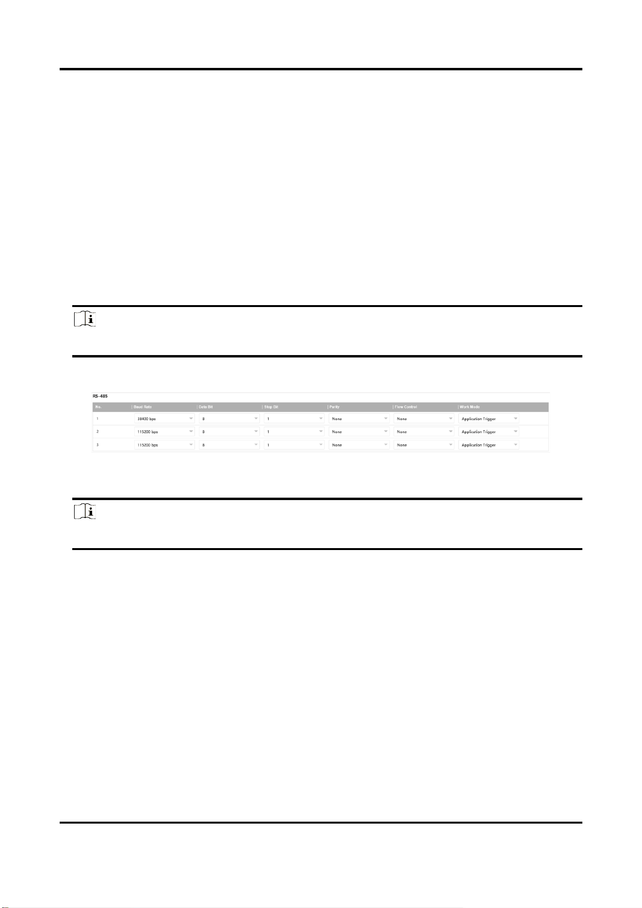
1. Go to Configuration → System → System Settings → Serial Port → RS-485.
Figure 10-1 Set RS-485
2. Set Baud Rate, Data Bit, Stop Bit, etc.
Note
The parameters should be same with those of the connected device.
3. Set Work Mode.
Application Trigger
Select it when the signal trigger devices (such as radar) are connected to the RS-485 serial
port of the device.
Transparent Channel
Select it when the other peripheral devices are connected to the RS-485 serial port of the
device for communication transmission.
GPS
The GPS devices are connected to the RS-485 serial port of the device for receiving location
data.
4. Click Save.

Tyre and Axle Recognition Unit User Manual
48
10.2 Set RS-232
Set RS-232 parameters if you need to debug the device via RS-232 serial port.
Before You Start
The debugging device has been connected via the RS-232 serial port.
Steps
1. Go to Configuration → System → System Settings → Serial Port → RS-232.
Figure 10-2 Set RS-232
2. Set Baud Rate, Data Bit, Stop Bit, etc.
Note
The parameters should be same with those of the connected device.
3. Select Work Mode.
Console
Select it when you need to debug the device via RS-232 serial port.
Transparent Channel
Select it, and the network command can be transmitted to RS-232 control command via the
RS-232 serial port.
Narrow Bandwidth Transmission
Reserved.
4. Click Save.

Tyre and Axle Recognition Unit User Manual
49
Chapter 11 Event and Alarm
11.1 Exception Alarm
Set exception alarm when the network is disconnected, the IP address is conflicted, etc.
Steps
Note
The supported exception types vary with different models. The actual device prevails.
1. Go to Configuration → Event → Alarm Linkage → Exception Event.
2. Select the exception type(s) and the linkage method.
3. Click Save.
11.2 Set Email
When the email is enabled and set, the device will send an email notification to all designated
receivers if an alarm event is detected.
Before You Start
Set the DNS server before using the email function. Go to Configuration → Network → Network
Parameters → Network Interface for DNS settings.
Steps
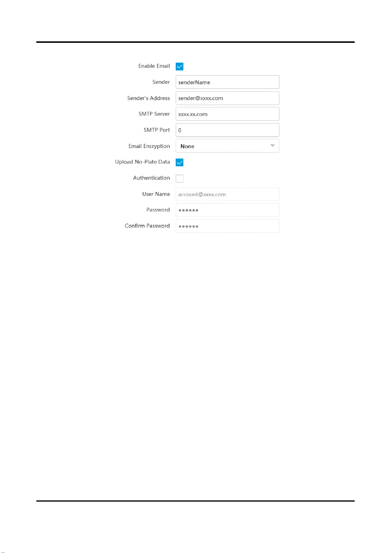
1. Go to Configuration → Network → Data Connection → Email.
2. Check Enable Email.
Tyre and Axle Recognition Unit User Manual
50
Figure 11-1 Set Email
3. Set email parameters.
1) Enter the sender's email information, including Sender, Sender's Address, SMTP Server, and
SMTP Port.
2) Select Email Encryption.
None
Emails are sent without encryption.
TLS
Emails are sent after being encrypted by TLS.
3) Optional: If you want to upload no-plate data, check Upload No-Plate Data.
4) Optional: If your email server requires authentication, check Authentication and enter your
user name and password to log in to the server.
5) Enter the receiver's information, including the receiver's name and address.
6) Optional: Click Test to see if the function is well configured.
4. Click Save.
11.3 Set Email Event
When the set event occurs, the device can be set to send an email with alarm information to the

Tyre and Axle Recognition Unit User Manual
51
user.
Before You Start
The email has been enabled and related email parameters have been configured.
Steps
1. Go to Configuration → Event → Alarm Linkage → Email Event.
2. Check Enable to trigger an email alarm.
3. Click Save.

Tyre and Axle Recognition Unit User Manual
52
Chapter 12 Safety Management
12.1 Manage User
The administrator can add, modify, or delete other accounts, and grant different permissions to
different user levels.
Steps
1. Go to Configuration → System → User Management → User List.
2. Select Password Level.
The password level of the added user should conform to the selected level.
3. Add a user.
1) Click Add.
2) Enter User Name and select Type.
3) Enter Admin Password, New Password, and confirm the password.
Caution
To increase security of using the device on the network, please change the password of your
account regularly. Changing the password every 3 months is recommended. If the device is
used in high-risk environment, it is recommended that the password should be changed every
month or week.
4) Assign remote permission to users based on needs.
User
Users can be assigned permission of viewing live video and changing their own passwords,
but no permission for other operations.
Operator
Operators can be assigned all permission except for operations on the administrator and
creating accounts.
5) Click OK.
4. Optional: You can do the following operations.
Change the password
and permission
Click to change the password and permission.
Delete the user
Click to delete the user.

Tyre and Axle Recognition Unit User Manual
53
12.2 Set IP Address Filtering
You can set the IP addresses allowable and not allowable to access the device.
Steps
1. Go to Configuration → System → Security → Security Settings.
2. Check Enable IP Address Filtering.
3. Set Filtering Mode.
Blocklist Mode
The added IP addresses are not allowed to access the device.
Allowlist Mode
The added IP addresses are allowed to access the device.
4. Click Add, enter the IP address, and click OK.
Note
The IP address only refers to the IPv4 address.
5. Optional: Edit, delete, or clear the added IP addresses.
6. Click Save.
12.3 Enable User Lock
To raise the data security, you are recommended to lock the current IP address.
Steps
1. Go to Configuration → System → Security → Security Service → Software.
2. Check Enable User Lock.
3. Click Save.
Result
When the times you entered incorrect passwords have reached the limit, the current IP address
will be locked automatically.
12.4 Set HTTPS
12.4.1 Create and Install Self-signed Certificate
HTTPS is a network protocol that enables encrypted transmission and identity authentication,

Tyre and Axle Recognition Unit User Manual
54
which improves the security of remote access.
Steps
1. Go to Configuration → Network → Network Parameters → HTTPS.
2. Select Create Self-signed Certificate.
3. Click Create.
4. Follow the prompt to enter Country/Region, Hostname/IP, Validity, and other parameters.
5. Click OK.
Result
The device will install the self-signed certificate by default.
12.4.2 Install Authorized Certificate
If the demand for external access security is high, you can create and install authorized certificate
via HTTPS protocol to ensure the data transmission security.
Steps
1. Go to Configuration → Network → Network Parameters → HTTPS.
2. Select Create certificate request first and continue the installation.
3. Click Create.
4. Follow the prompt to enter Country/Region, Hostname/IP, Validity, and other parameters.
5. Click Download to download the certificate request and submit it to the trusted authority for
signature.
6. Import certificate to the device.
–
Select Signed certificate is available, start the installation directly. Click Browse and Install
to import the certificate to the device.
–
Select Create the certificate request first and continue the installation. Click Browse and
Install to import the certificate to the device.
7. Click Save.
12.5 Set SSH
To raise network security, disable SSH service. The configuration is only used to debug the device
for the professionals.
Steps
1. Go to Configuration → System → Security → Security Service → Software.
2. Disable SSH Service.
3. Click Save.

Tyre and Axle Recognition Unit User Manual
55
12.6 Set RTSP Authentication
You can improve network access security by setting RTSP authentication.
Steps
1. Go to Configuration → System → Security → Security Settings.
2. Select RTSP Authentication.
digest
The device only supports digest authentication.
digest/basic
The device supports digest or basic authentication.
3. Click Save.
12.7 Set Timeout Logout
You can improve network access security by setting timeout logout.
Steps
1. Go to Configuration → System → Security → Security Service → Timeout Logout.
2. Enable timeout logout for static page.
3. Set Max. Timeout.
4. Click Save.
Result
When the page static time exceeds the set time, the device will automatically log out.
12.8 Set Password Validity Period
You can improve network access security by setting password validity period.
Steps
1. Go to Configuration → System → Security → Security Service → Password Validity Period.
2. Select Validity Type.
–
Select Permanent. The password will be permanently valid.
–
Select Daily and set Password Expiry Time. It will prompt you that the password is expired
according to the set password expiry time, and you need to set the new password.
3. Click Save.

Tyre and Axle Recognition Unit User Manual
56
Chapter 13 Maintenance
13.1 View Device Information
Basic Information and Algorithms Library Version
Go to Configuration → System → System Settings → Basic Information to view the basic
information and algorithms library version of the device.
You can edit Device Name and Device No. The device No. is used to control the device. It is
recommended to reserve the default value.
Device Status
Go to Configuration → System → System Settings → Device Status to view the device status.
13.2 Log
13.2.1 Enable System Log Service
The security audit logs refer to the security operation logs. You can search and analyze the security
log files of the device so as to find out the illegal intrusion and troubleshoot the security events.
Security audit logs can be saved on device internal storage. The log will be saved every half hour
after device booting. Due to limited storage space, you are recommended to save the logs on a log
server.
Steps
1. Go to Configuration → System → Security → Security Service → Log Audit Service.
2. Enable system log service.
3. Enter IP Address and Port of the log server.
4. Click Save.
Result
The device will upload the security audit logs to the log server regularly.
13.2.2 Search Log
Log helps to locate and troubleshoot problems.
Steps
1. Go to Configuration → System → Maintenance → Log Search.
2. Set search conditions.

Tyre and Axle Recognition Unit User Manual
57
3. Click Search.
The matched log files will be displayed on the log list.
4. Optional: Click Export to save the log files to your computer.
13.2.3 Enable Log According to Module
You can enable the log according to the module for debugging.
Steps
Note
The function varies with different models. The actual device prevails.
1. Go to Configuration → System → Maintenance → Debug → Log.
2. Check the module(s) according to your needs.
Note
If you want to disable the log automatically, you can enable auto close log and set close time.
3. Click Save.
13.3 Upgrade
Upgrade the system when you need to update the device version.
Before You Start
Prepare the upgrade file. If the upgrade file is a compressed package, it needs to be decompressed
into the .dav format.
Steps
1. Go to Configuration → System → Maintenance → Upgrade & Maintenance → Upgrade.
2. Click Browse to select the upgrade file.
3. Click Upgrade.
4. Click OK in the popup window.
Note
The upgrade process will take 1 to 10 minutes. Do not cut off the power supply.
Result
The device will reboot automatically after upgrade.

Tyre and Axle Recognition Unit User Manual
58
13.4 Reboot
When the device needs to be rebooted, reboot it via the software instead of cutting off the power
directly.
Steps
1. Go to Configuration → System → Maintenance → Upgrade & Maintenance → Device
Maintenance.
2. Click Reboot.
3. Click OK to reboot the device.
Note
You can also click Reboot on the upper right corner of the page to reboot the device.
13.5 Restore Parameters
When the device is abnormal caused by the incorrect set parameters, you can restore the
parameters.
Steps
1. Go to Configuration → System → Maintenance → Upgrade & Maintenance → Device
Maintenance.
2. Select the restoration mode.
–
Click Reboot, and click OK to reboot the device.
–
Click Restore, and select the parameters to be saved instead of being restored. Click OK. Then
the parameters except the IP parameters, user parameters, and the saved parameters will be
restored to the default settings.
–
Click Restore Factory Settings and click OK to restore all the parameters to the factory
settings.
3. Click OK.
13.6 Synchronize Time
Synchronize the device time when it is inconsistent with the actual time.
Steps
1. Go to Configuration → System → System Settings → Time Settings.
2. Select Time Zone.
3. Select Sync Mode.
Satellite Time
Select it to synchronize the device time with that of the satellite. Set Interval.

Tyre and Axle Recognition Unit User Manual
59
SDK
If the remote host has been set for the device, select it to synchronize time via the remote
host.
ONVIF
Select it to synchronize time via the third-party device.
No
Select it to disable time synchronization.
All
Select it, and you can select any mode above.
Note
The time synchronization modes vary with different models. The actual device prevails.
4. Click Save.
13.7 Set DST
If the region where the device is located adopts Daylight Saving Time (DST), you can set this
function.
Steps
1. Go to Configuration → System → System Settings → DST.
2. Check Enable DST.
3. Set Start Time, End Time, and DST Bias.
4. Click Save.
13.8 Debug
Note
The debug configurations below are only provided to debug the device by the professionals.
13.8.1 Debug Device
You can enable the functions to debug the device.
Steps
1. Go to Configuration → Capture → Advanced → System Service.
2. Check the debug information according to your needs.
Enable Algorithm POS Information Debug

Tyre and Axle Recognition Unit User Manual
60
The algorithm POS information will be overlaid on the playback image when you play back
the video with the dedicated tool.
Enable Positioning Frame Debug
The positioning frames of vehicle bodies and license plates will be overlaid on the captured
pictures.
Enable Closed Positioning Frame
The bottom lines of the positioning frames on the captured pictures will display. The frames
will be closed.
Enable LPR Area Frame
The LPR area frames on the captured pictures will be displayed.
LPR Area Frame Y-Direction Deviation
If the license plate is not included in the LPR area frame, adjust the LPR area frame position in
the Y-direction by pixel. Enter the deviation pixel in the text field. The value = image height ×
(deviation distance/100). Set the value according to the actual needs. Range: -100% to 100%.
The LPR area frame moves up if the value is negative, and it moves down if the value is
positive.
Enable Multi-Way Upload
Data will be uploaded in multiple set ways simultaneously.
3. Click Save.
13.8.2 Vehicle Capture and Recognition Service
Set the vehicle capture and recognition service to debug the device.
Steps
1. Go to Configuration → Capture → Advanced → Vehicle Capture and Recognition Service.
2. Check the service according to your needs.
Filter Checkpoint Capture of Same Vehicle
It is used to debug the device with the same vehicle. When the same vehicle is triggered
many times during a short period in the scene, the checkpoint pictures of the vehicle will not
be captured.
Note
For some models, you can set Effective Time of Filtering.
Capture Frame Priority Mode
Check it to adopt license plate recognition results that processed by the single frame
recognition algorithm.
Do Not Capture Reverse-driving Vehicle

Tyre and Axle Recognition Unit User Manual
61
The reverse-driving vehicles will not be captured. For example, if you need to capture the
vehicles driven from the west to the east, enable the function and the vehicles driven from
the east to the west will not be captured.
VCA Alarm for Target Picture Matting
Check it to upload alarms via VCA protocol if the target picture matting is enabled.
3. Click Save.
13.8.3 Set Image Format
You can enable smartJPEG which can save the storage space without influencing the resolution.
Steps
1. Go to Configuration → Capture → Advanced → Image Service.
2. Check smartJPEG.
3. Set image quality according to your needs.
Note
The higher the value is, the better the image quality is.
4. Optional: Set Expansion Ratio of License Plate Image to expand the cutout scale of license plate
image.
5. Click Save.
13.9 Export Parameters
You can export the parameters of one device, and import them to another device to set the two
devices with the same parameters.
Steps
1. Go to Configuration → System → Maintenance → Upgrade & Maintenance → Data Export.
2. Click Export after Configuring Parameters.
3. Set an encryption password, confirm the password, and click OK.
Note
The password is used for importing the configuration file of the current device to other devices.
4. Select the saving path, and enter the file name.
5. Click Save.

Tyre and Axle Recognition Unit User Manual
62
13.10 Import Configuration File
Import the configuration file of another device to the current device to set the same parameters.
Before You Start
Save the configuration file to the computer.
Steps
Caution
Importing configuration file is only available to the devices of the same model and same version.
1. Go to Configuration → System → Maintenance → Upgrade & Maintenance → Advanced
Settings → Data Import.
2. Select Importing Method.
Note
If you select Import Part, check the parameters to be imported.
3. Click Browse to select the configuration file.
4. Click Import.
5. Enter the password which is set when the configuration file is exported, and click OK.
6. Click OK on the popup window.
Result
The parameters will be imported, and the device will reboot.
13.11 Export Debug File
The technicians can export the debug file to troubleshoot and maintain the device.
Steps
1. Go to Configuration → System → Maintenance → Upgrade & Maintenance → Data Export.
2. Click Export after Debug File.
3. Select the saving path, and enter the file name.
4. Click Save.
13.12 Export Diagnosis Information
The technicians can export the diagnosis information to troubleshoot and maintain the device.
Steps
1. Go to Configuration → System → Maintenance → Upgrade & Maintenance → Data Export.

Tyre and Axle Recognition Unit User Manual
63
2. Click Export after Diagnosis Information.
3. Select the saving path, and enter the file name.
4. Click Save.

UD34252B
