
Panic Alarm Station
Configuration Guide

Panic Alarm Station Configuration Guide
i
Legal Information
© 2020 Hangzhou Hikvision Digital Technology Co., Ltd. All rights reserved.
About this Manual
The Manual includes instructions for using and managing the Product. Pictures, charts, images and
all other information hereinafter are for description and explanation only. The information
contained in the Manual is subject to change, without notice, due to firmware updates or other
reasons. Please find the latest version of this Manual at the Hikvision website
(https://www.hikvision.com/).
Please use this Manual with the guidance and assistance of professionals trained in supporting the
Product.
Trademarks
and other Hikvision's trademarks and logos are the properties of
Hikvision in various jurisdictions.
Other trademarks and logos mentioned are the properties of their respective owners.
Disclaimer
TO THE MAXIMUM EXTENT PERMITTED BY APPLICABLE LAW, THIS MANUAL AND THE PRODUCT
DESCRIBED, WITH ITS HARDWARE, SOFTWARE AND FIRMWARE, ARE PROVIDED “AS IS” AND
“WITH ALL FAULTS AND ERRORS”. HIKVISION MAKES NO WARRANTIES, EXPRESS OR IMPLIED,
INCLUDING WITHOUT LIMITATION, MERCHANTABILITY, SATISFACTORY QUALITY, OR FITNESS FOR
A PARTICULAR PURPOSE. THE USE OF THE PRODUCT BY YOU IS AT YOUR OWN RISK. IN NO EVENT
WILL HIKVISION BE LIABLE TO YOU FOR ANY SPECIAL, CONSEQUENTIAL, INCIDENTAL, OR INDIRECT
DAMAGES, INCLUDING, AMONG OTHERS, DAMAGES FOR LOSS OF BUSINESS PROFITS, BUSINESS
INTERRUPTION, OR LOSS OF DATA, CORRUPTION OF SYSTEMS, OR LOSS OF DOCUMENTATION,
WHETHER BASED ON BREACH OF CONTRACT, TORT (INCLUDING NEGLIGENCE), PRODUCT
LIABILITY, OR OTHERWISE, IN CONNECTION WITH THE USE OF THE PRODUCT, EVEN IF HIKVISION
HAS BEEN ADVISED OF THE POSSIBILITY OF SUCH DAMAGES OR LOSS.
YOU ACKNOWLEDGE THAT THE NATURE OF INTERNET PROVIDES FOR INHERENT SECURITY RISKS,
AND HIKVISION SHALL NOT TAKE ANY RESPONSIBILITIES FOR ABNORMAL OPERATION, PRIVACY
LEAKAGE OR OTHER DAMAGES RESULTING FROM CYBER-ATTACK, HACKER ATTACK, VIRUS
INSPECTION, OR OTHER INTERNET SECURITY RISKS; HOWEVER, HIKVISION WILL PROVIDE TIMELY
TECHNICAL SUPPORT IF REQUIRED.
YOU AGREE TO USE THIS PRODUCT IN COMPLIANCE WITH ALL APPLICABLE LAWS, AND YOU ARE
SOLELY RESPONSIBLE FOR ENSURING THAT YOUR USE CONFORMS TO THE APPLICABLE LAW.
ESPECIALLY, YOU ARE RESPONSIBLE, FOR USING THIS PRODUCT IN A MANNER THAT DOES NOT
INFRINGE ON THE RIGHTS OF THIRD PARTIES, INCLUDING WITHOUT LIMITATION, RIGHTS OF
PUBLICITY, INTELLECTUAL PROPERTY RIGHTS, OR DATA PROTECTION AND OTHER PRIVACY RIGHTS.
YOU SHALL NOT USE THIS PRODUCT FOR ANY PROHIBITED END-USES, INCLUDING THE
DEVELOPMENT OR PRODUCTION OF WEAPONS OF MASS DESTRUCTION, THE DEVELOPMENT OR

Panic Alarm Station Configuration Guide
ii
PRODUCTION OF CHEMICAL OR BIOLOGICAL WEAPONS, ANY ACTIVITIES IN THE CONTEXT RELATED
TO ANY NUCLEAR EXPLOSIVE OR UNSAFE NUCLEAR FUEL-CYCLE, OR IN SUPPORT OF HUMAN
RIGHTS ABUSES.
IN THE EVENT OF ANY CONFLICTS BETWEEN THIS MANUAL AND THE APPLICABLE LAW, THE LATER
PREVAILS.
Panic Alarm Station Configuration Guide
iii
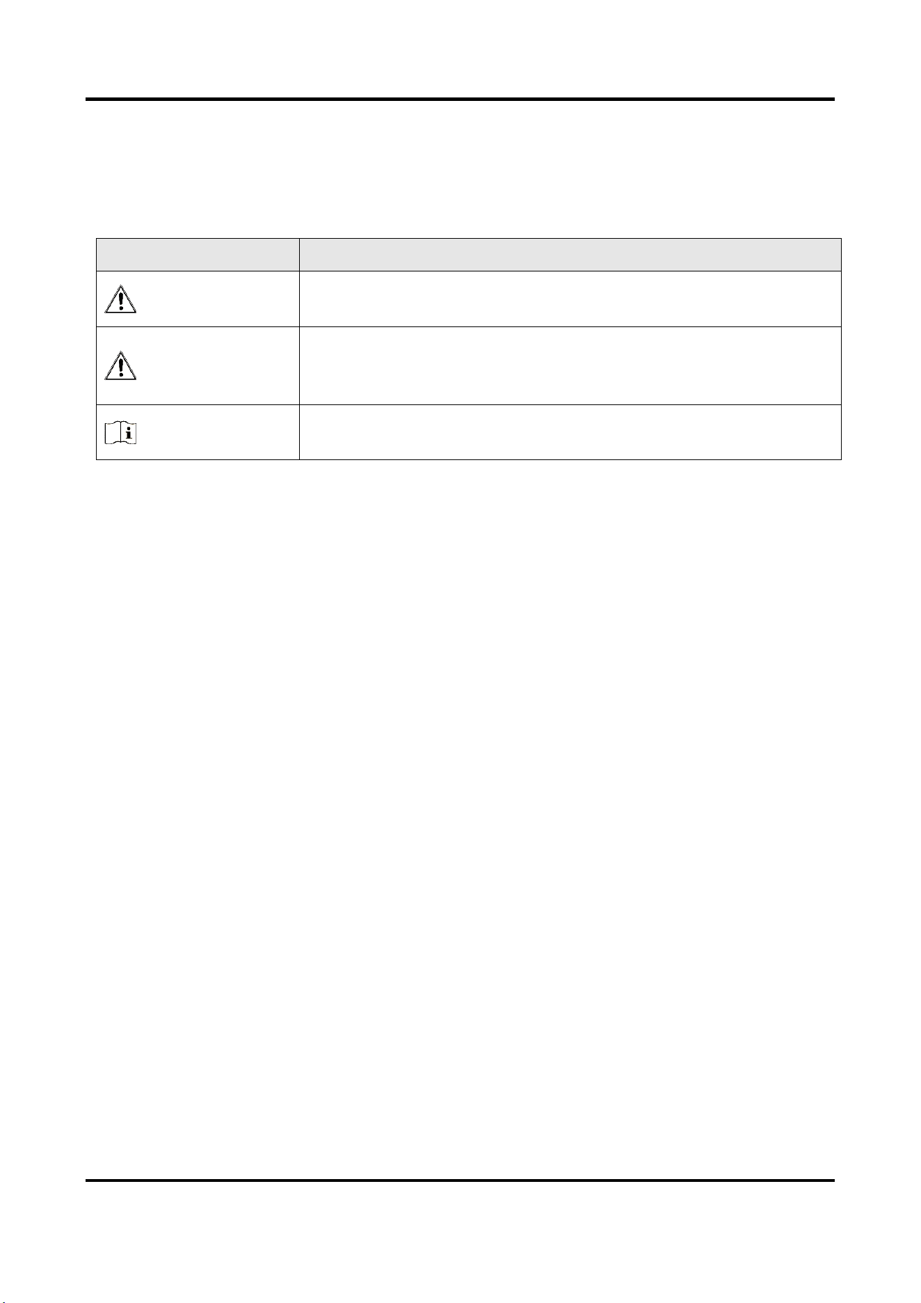
Symbol Conventions
The symbols that may be found in this document are defined as follows.
Symbol
Description
Danger
Indicates a hazardous situation which, if not avoided, will or could
result in death or serious injury.
Caution
Indicates a potentially hazardous situation which, if not avoided,
could result in equipment damage, data loss, performance
degradation, or unexpected results.
Note
Provides additional information to emphasize or supplement
important points of the main text.

Panic Alarm Station Configuration Guide
iv
Regulatory Information
FCC Information
Please take attention that changes or modification not expressly approved by the party
responsible for compliance could void the user’s authority to operate the equipment.
FCC compliance: This equipment has been tested and found to comply with the limits for a Class B
digital device, pursuant to part 15 of the FCC Rules. These limits are designed to provide
reasonable protection against harmful interference in a residential installation. This equipment
generates, uses and can radiate radio frequency energy and, if not installed and used in
accordance with the instructions, may cause harmful interference to radio communications.
However, there is no guarantee that interference will not occur in a particular installation. If this
equipment does cause harmful interference to radio or television reception, which can be
determined by turning the equipment off and on, the user is encouraged to try to correct the
interference by one or more of the following measures:
—Reorient or relocate the receiving antenna.
—Increase the separation between the equipment and receiver.
—Connect the equipment into an outlet on a circuit different from that to which the receiver is
connected.
—Consult the dealer or an experienced radio/TV technician for help
FCC Conditions
This device complies with part 15 of the FCC Rules. Operation is subject to the following two
conditions:
1. This device may not cause harmful interference.
2. This device must accept any interference received, including interference that may cause
undesired operation.
EU Conformity Statement
This product and - if applicable - the supplied accessories too are marked with
"CE" and comply therefore with the applicable harmonized European standards
listed under the EMC Directive 2014/30/EU, the RoHS Directive 2011/65/EU
2012/19/EU (WEEE directive): Products marked with this symbol cannot be
disposed of as unsorted municipal waste in the European Union. For proper
recycling, return this product to your local supplier upon the purchase of
equivalent new equipment, or dispose of it at designated collection points. For
more information see: www.recyclethis.info

Panic Alarm Station Configuration Guide
v
Contents
Chapter 1 Overview.................................................................................................................... 1
Chapter 2 Activation................................................................................................................... 2
2.1 Activate via SADP .................................................................................................................. 2
2.2 Activate Device via Client Software ...................................................................................... 3
Chapter 3 Remote Settings ......................................................................................................... 5
3.1 Device Management ............................................................................................................. 5
3.1.1 Add Device to the Client Software ............................................................................ 5
3.1.2 Edit Network Parameters ........................................................................................... 6
3.2 Network Configuration ......................................................................................................... 6
3.2.1 Basic Settings .............................................................................................................. 6
3.2.2 Set DNS ....................................................................................................................... 8
3.2.3 Set NAT ....................................................................................................................... 8
3.2.4 Set Alarm Center ...................................................................................................... 10
3.2.5 Set SIP ....................................................................................................................... 11
3.2.6 Data Limit ................................................................................................................. 12
3.2.7 Set Wireless Dialing .................................................................................................. 13
3.2.8 Set Hik-Connect ........................................................................................................ 15
3.2.9 Access the Platform .................................................................................................. 16
3.2.10 Set Call Center Parameters .................................................................................... 16
3.2.11Set Intercom Parameters ........................................................................................ 17
3.3 Alarm Settings ..................................................................................................................... 18
3.3.1 Set Zone .................................................................................................................... 18
3.3.2 Set Relay ................................................................................................................... 20
3.3.3 Set Call Waiting ........................................................................................................ 21
3.3.4 Set Voice Prompt ...................................................................................................... 22
3.4 Alarm Management ............................................................................................................ 23
3.4.1 Manage Relay ........................................................................................................... 23
3.4.2 Manage Audio Input/Output ................................................................................... 23
3.4.3 Manage Siren ............................................................................................................ 24

Panic Alarm Station Configuration Guide
vi
3.4.4 Manage Strobe Light ................................................................................................ 25
3.4.5 Manage Audio File.................................................................................................... 25
3.4.6 Manage Strobe Light Flicking ................................................................................... 27
3.5 Event Settings ...................................................................................................................... 28
3.5.1 Schedule Settings ..................................................................................................... 28
3.5.2 Set Audio Exception Detection ................................................................................ 34
3.6 Video & Audio Settings ....................................................................................................... 35
3.6.1 Video & Audio Settings ............................................................................................ 35
3.6.2 Set Display ................................................................................................................ 37
3.6.3 Set Image Parameters .............................................................................................. 39
3.6.4 Set Intercom Audio .................................................................................................. 40
3.7 System Settings ................................................................................................................... 40
3.7.1 Set Time .................................................................................................................... 40
3.7.2 Set System Parameters ............................................................................................ 41
3.7.3 Set Security ............................................................................................................... 41
3.7.4 Set Password ............................................................................................................ 41
3.7.5 Set User ..................................................................................................................... 43
3.7.6 Search for Log ........................................................................................................... 44
3.7.7 Maintain the System ................................................................................................ 44
3.7.8 Check Video & Audio Status .................................................................................... 46
3.7.9 View Device Information ......................................................................................... 47
3.8 Set Camera ........................................................................................................................... 47
3.8.1 Add Camera .............................................................................................................. 48
3.8.2 Set Video Parameters ............................................................................................... 49
3.8.3 Set WDR .................................................................................................................... 49
3.8.4 Set Other Parameters ............................................................................................... 50
3.9 Storage Settings ................................................................................................................... 51
3.9.1 Initialize HHD ............................................................................................................ 51
3.9.2 Search for File ........................................................................................................... 52
3.10 Check Status ...................................................................................................................... 52
3.10.1 Check Zone Status .................................................................................................. 52


Panic Alarm Station Configuration Guide
1
Chapter 1 Overview
Description
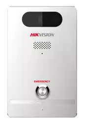
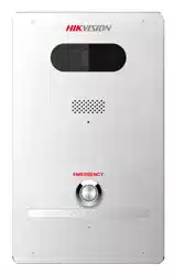
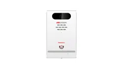
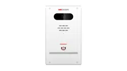
DS-PEA series of active panic alarm station supports dual network ports. It provides200W high-
definition camera, center call, strobe light work schedule, two-way audio, remote/local open
electric lock, external network camera to increase field of view and other functions. The device
supports video call with the center, and linkage with the surrounding cameras and external lamp,
sound box, etc. It helps to realize alarm aid in emergency.
The device is mainly used in classrooms, corridors, laboratories, dormitories, offices, hospital
wards, etc.
Key Features
● Supports network adaptive, video and audio adaptive, and low video and audio delay in the case
of network packet loss
● Two-way audio with center
● Video collection and all-day monitoring with 2 MP HD IR camera
● Supports accessing one channel of network camera
● Supports H.264/H.265
● Supports G.711U, G726, OPUS, and AAC
● Supports video storage
● Built-in omnidirectional microphone to realize 2 m two-way audio distance, 10 m listening
distance
● Multiple network protocols including SIP, Private SIP, ISUP, and RTSP
● 3.5 mm standard audio interface for external active speaker
● Supports anti-breaking with full-band high-quality speaker and pickup
● Optional wireless communication module to meet different network environments
● Supports dual network ports

Panic Alarm Station Configuration Guide
2
Chapter 2 Activation
In order to protect personal security and privacy and improve the network security level, you
should activate the device the first time you connect the device to a network.
2.1 Activate via SADP
SADP is a tool to detect, activate and modify the IP address of the device over the LAN.
Before You Start
● Get the SADP software from the supplied disk or the official website
http://www.hikvision.com/en/, and install the SADP according to the prompts.
● The device and the PC that runs the SADP tool should be within the same subnet.
The following steps show how to activate a device and modify its IP address. For batch activation
and IP addresses modification, refer to User Manual of SADP for details.
Steps
1. Run the SADP software and search the online devices.
2. Find and select your device in online device list.
3. Input new password (admin password) and confirm the password.
Caution
STRONG PASSWORD RECOMMENDED-We highly recommend you create a strong password of
your own choosing (using a minimum of 8 characters, including upper case letters, lower case
letters, numbers, and special characters) in order to increase the security of your product. And
we recommend you reset your password regularly, especially in the high security system,
resetting the password monthly or weekly can better protect your product.
4. Click Activate to start activation.
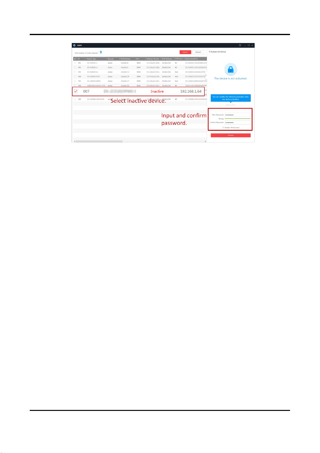
Panic Alarm Station Configuration Guide
3
Figure 2-1 Activate via SADP
Status of the device becomes Active after successful activation.
5. Modify IP address of the device.
1) Select the device.
2) Change the device IP address to the same subnet as your computer by either modifying the IP
address manually or checking Enable DHCP.
3) Input the admin password and click Modify to activate your IP address modification.
2.2 Activate Device via Client Software
Before You Start
● Get the iVMS-4200 client software from the supplied disk or the official website
http://www.hikvision.com/en/. Install the software by following the prompts.
● Get the Guarding Vision client software from the supplied disk. Install the software by following
the prompts.
● The device and the PC that runs the software should be in the same subnet.
Steps
1. Run the client software.
2. Enter Device Management → Device in the Maintenance and Management list.
3. Click Online Device.
4. Check the device status from the online device list, and select an inactive device.
5. Click Activate.
6. Create and confirm the admin password of the device.

Panic Alarm Station Configuration Guide
4
Caution
STRONG PASSWORD RECOMMENDED-We highly recommend you create a strong password of
your own choosing (using a minimum of 8 characters, including upper case letters, lower case
letters, numbers, and special characters) in order to increase the security of your product. And
we recommend you reset your password regularly, especially in the high security system,
resetting the password monthly or weekly can better protect your product.
7. Click OK to start activation.
Device status will change to Active after successful activation.
8. Edit IP address of the device.
1) Select a device and click on the online device list.
2) Change the device IP address to the same subnet with your computer.
3) Enter the admin password of the device and click OK to complete modification.
9. Optional: Check the device on the online device list and click Add to add the device to the
device list.
Panic Alarm Station Configuration Guide
5
Chapter 3 Remote Settings
In the client software, go to Control Panel → Device Mnagement, click and select the device in the
Device for Management, and click Remote Configuration to go to Remote Configuration page.
Note
● The device should be activated the first time it is used to log in and use properly. See Activation
to activate the device.
● You need to add the device to the client software before configure it. See Add Device to the
Client Software.
● Get the client software from the technical support, and install the software according to the
prompts.
3.1 Device Management
3.1.1 Add Device to the Client Software
Before You Start
Activate the device and ensure that the device is on the same subnet as the PC.
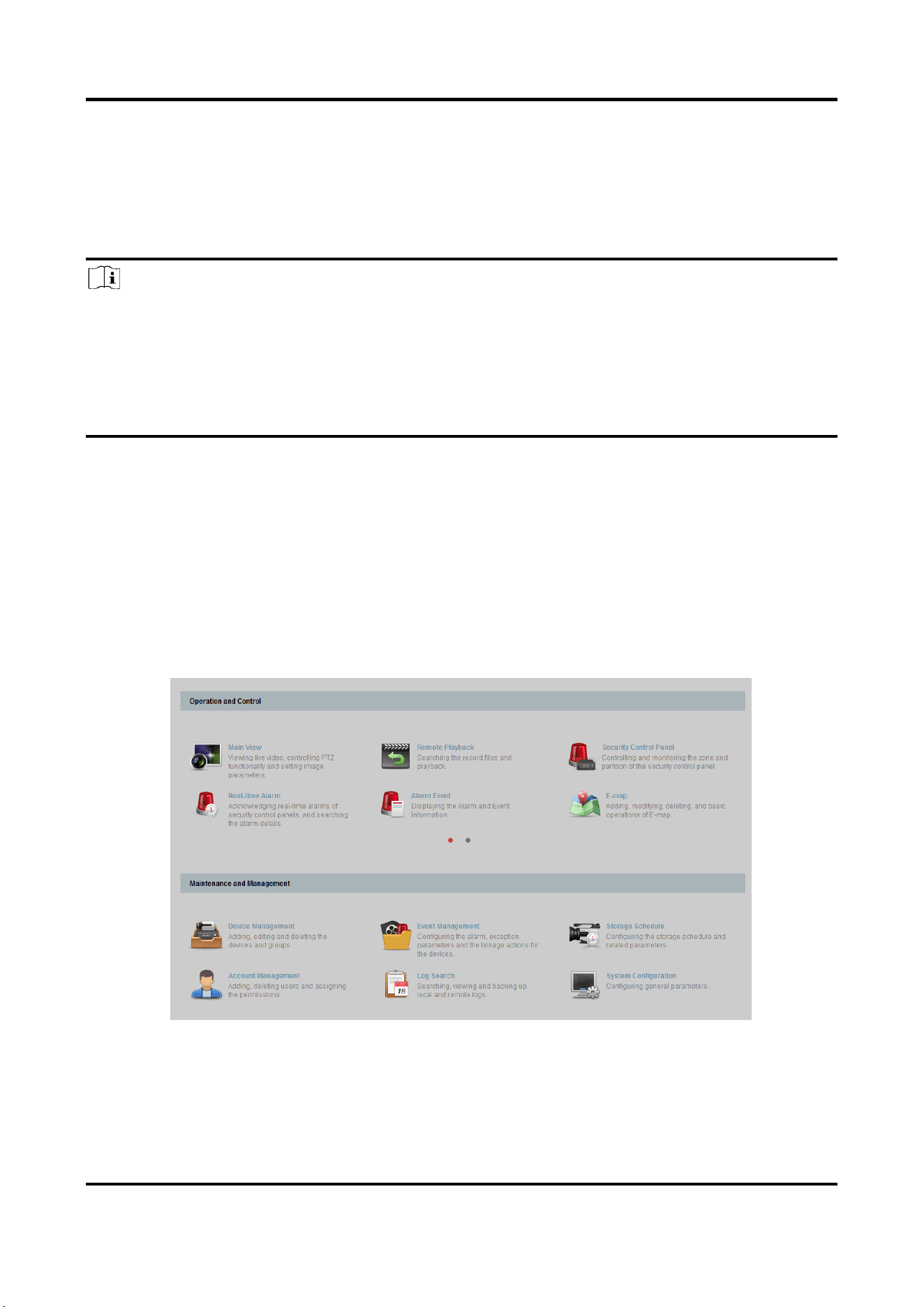
Figure 3-1 Client Software Main Page
In the client software, go to Device Management → Device on the Maintenance and
Management list. You can add devices to client software by several methods on the device

Panic Alarm Station Configuration Guide
6
management page. The following describes how to add devices through IP/Domain Name. For
more information, see iVMS-4200 Client Software User Manual.
Steps
1. On the Device page, click Add.
2. Select IP/Domain as the adding mode, edit the device information, including Name, Address,
Port, User Name, and Password.
3. Check Import to Group.
4. Click Add to add the device.
3.1.2 Edit Network Parameters
Edit the device network parameters so that the device IP address is in the same subnet as the
computer IP address.
You can edit the network parameters through the SADP software, or the client software. The SADP
software is taken as an example for explanation.
Steps
1. Run the SADP software, check the activated device, and edit the IP Address, Subnet Mask,
Gateway and other parameters in the Modify Network Parameters list on the right.
Note
If check Enable DHCP, the device can automatically obtain network parameters.
2. Enter the activation password, click Modify, and the prompt Modify parameters is successful
indicate that the settings take effect.
3.2 Network Configuration
3.2.1 Basic Settings
Configure network mode, IP address, NIC and NIC type, subnet mask, gateway, MAC address, MTU
settings, and port No. for device.
Before You Start
Make sure the cable of the device is connected.
Panic Alarm Station Configuration Guide
7
Steps
Note
The network mode is multiple networks mode, you can set the basic network parameters for
NIC 1 and NIC 2.
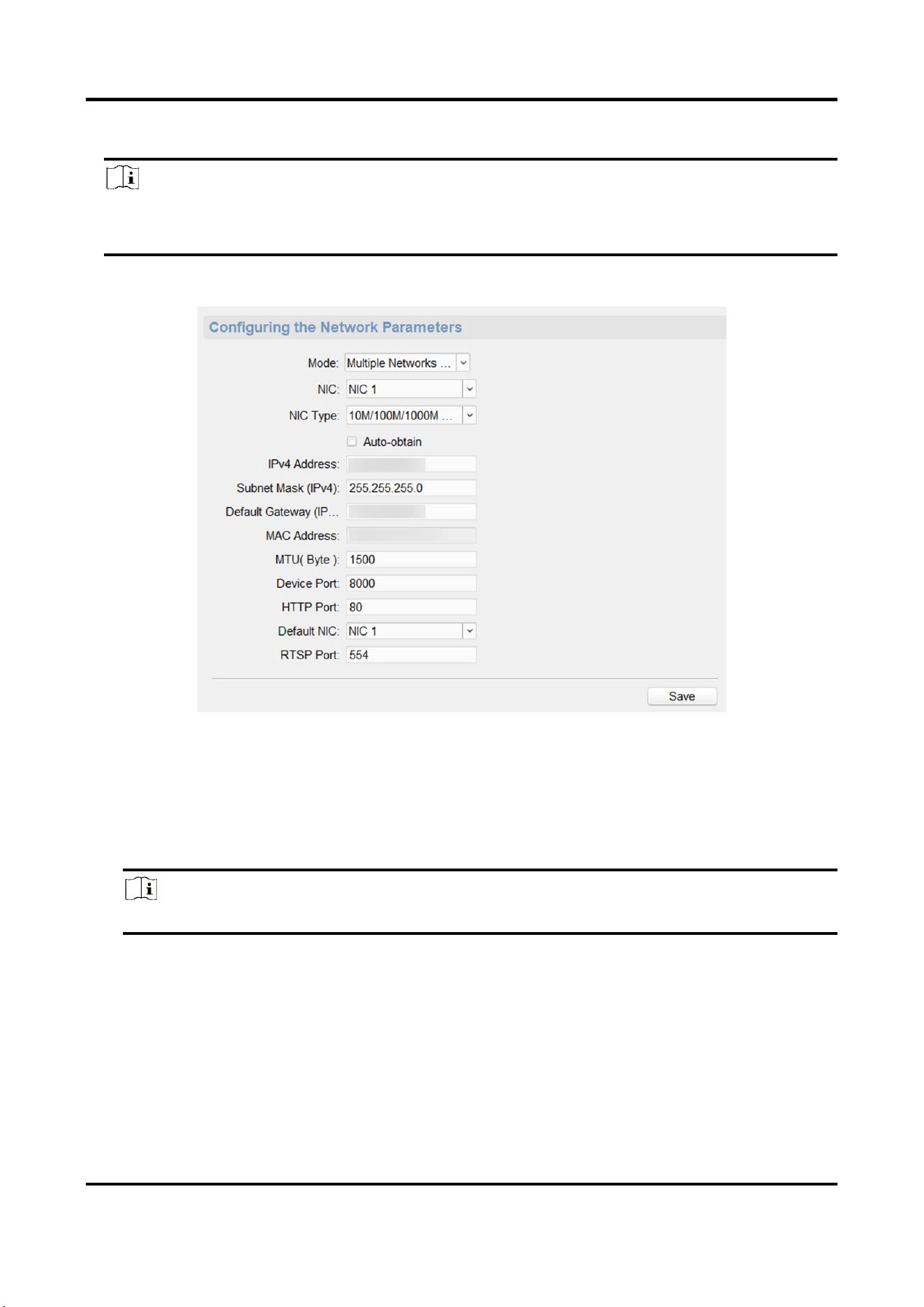
1. On the Remote Configuration page, go to Network → General.
Figure 3-2 Network Basic Settings Page
2. Select the NIC and the NIC type.
3. Set the network address.
– Automatically obtain the network address
Check Auto-obtain, the device automatically obtains the network address (IPv4 Address,
Subnet Mask (IPv4), Default Gateway (IPv4)) through DHCP.
Note
NIC 1 and NIC 2 are independent of DHCP.
– Manually set the network address
According to the actual network environment, manually set the network address IPv4
Address, Subnet Mask (IPv4), Default Gateway (IPv4).
4. Set the MTU(Byte), Device Port, HTTP port, RTSP port, and Default NIC for the device.
MTU(Byte)
Maximum transmission unit, which refers to the maximum packet size passed by TCP/UDP
protocol network transmission. The default is 1500.
Panic Alarm Station Configuration Guide
8
Device Port
The default device port number is 8000.
HTTP port
The default port number is 80, and it can be changed to any port No. which is not occupied.
RTSP port
The default port number is 554 and it can be changed to any port No. ranges from 1 to 65535.
Default NIC
The default NIC is NIC 1 and it can be set to NIC 1 or NIC 2.
5. Click Save to save the settings.
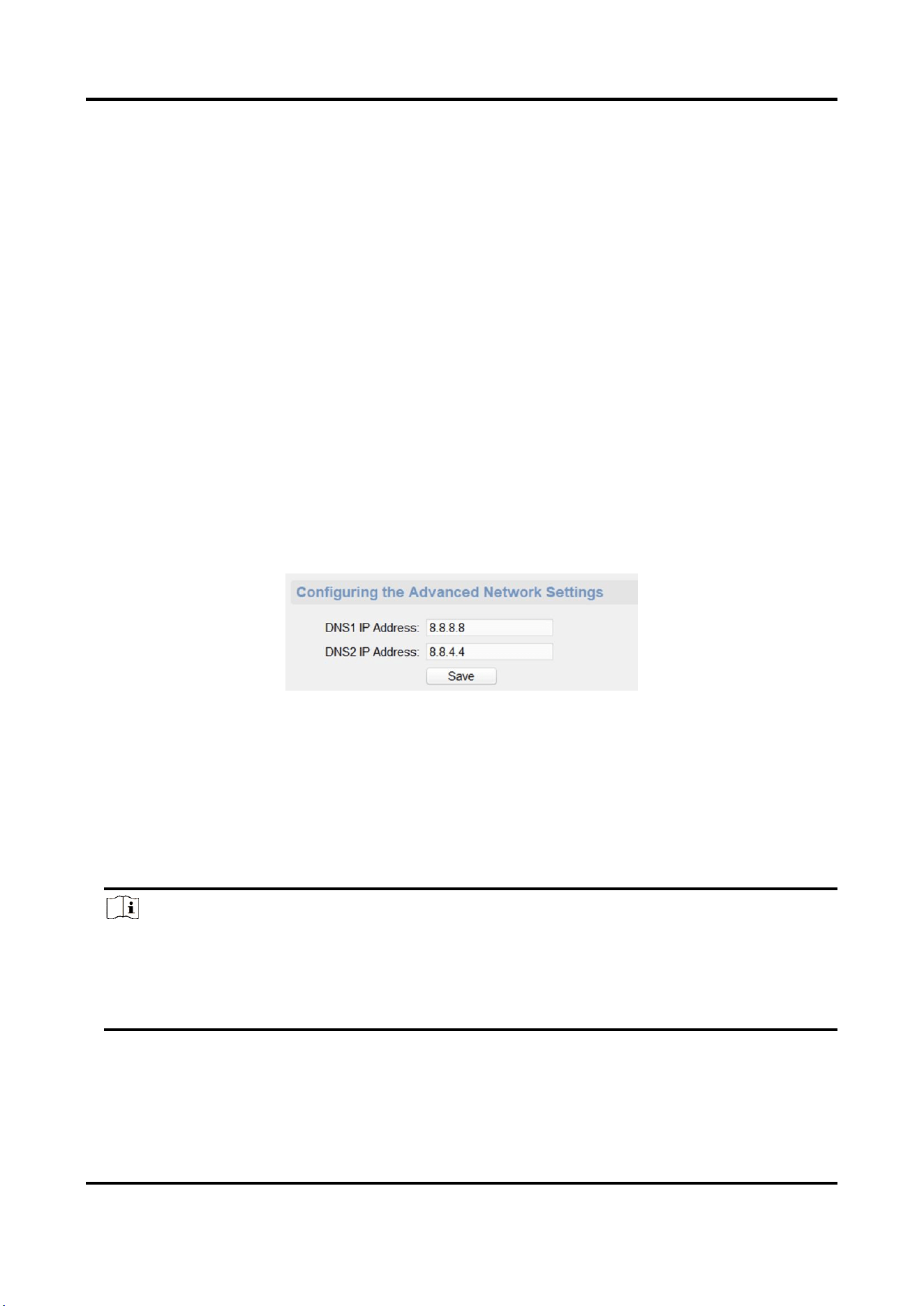
3.2.2 Set DNS
When the device accesses the network through the domain name, you need to configure the
correct and available DNS server IP address.
The device supports 2 DNS address.
On the Remote Configuration page, go to Network → DNS, set the DNS server IP address and click
Save to save the settings.
Figure 3-3 DNS Setting Page
3.2.3 Set NAT
Enable the UPnP function, and you don't need to configure the port mapping for each port, and
the device is connected to the Wide Area Network via the router.
Steps
Note
Universal Plug and Play (UPnP™) is a networking architecture that provides compatibility among
networking equipment, software and other hardware devices. The UPnP protocol allows devices
to connect seamlessly and to simplify the implementation of networks in the home and
corporate environments.
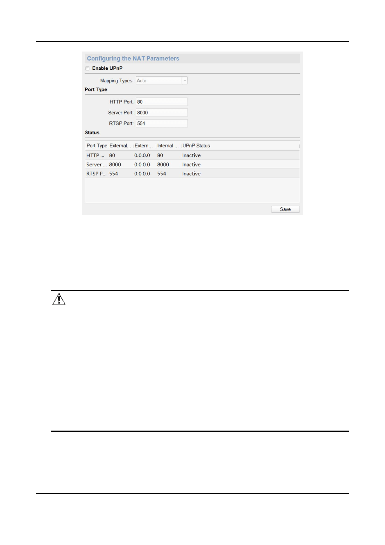
1. On the Remote Configuration page, go to Network → NAT.
Panic Alarm Station Configuration Guide
9
Figure 3-4 NAT Setting Page
2. Check Enable UPnP, and set Mapping Types as Manual or Auto.
– Set Mapping Types as Auto
The Ports are read-only, and the external ports are set by the router automatically.
– Set Mapping Types as Manual
You can edit the external port on your demand. And then you should enable UPnP function
on the router.
Caution
Please do not arbitrarily edit the default port number. If there is a port conflict and you need
to edit the port number, please modify the port number as follows.
HTTP Port
By default, the value of the HTTP port No. is 80.
Server Port
By default, the value of the Server port No. is 8000. If the value is changed, you need to
enter the server port number on the login page when you log in the device by client
software.
RTSP Port
Real-time transport protocol port, please make sure that the port you modified is available.
By default, the value of the RTSP port No. is 554.
3. Click Save to save the settings.
Panic Alarm Station Configuration Guide
10
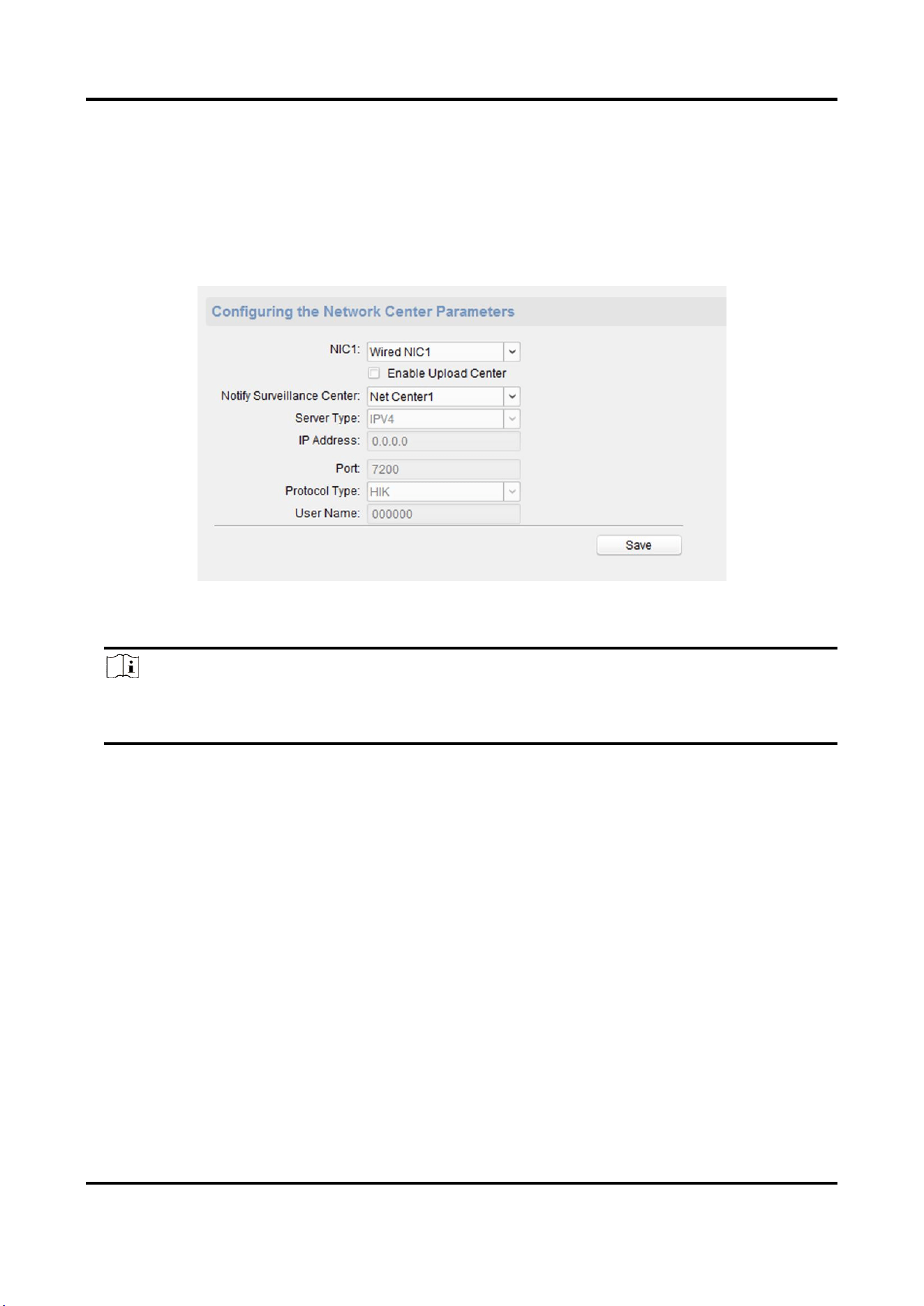
3.2.4 Set Alarm Center
Configure the alarm center. When an alarm is triggered, the alarm information can be uploaded to
the configured alarm center.
Steps
1. On the Remote Configuration page, go to Network → Network Center Configure.
Figure 3-5 Alarm Center Configuration
2. Select a NIC.
Note
The device supports two wired networks and one wireless network. Each network supports
uploading alarm information to one alarm center.
3. Check Enable Upload Center to enable the alarm center, and set the upload center parameters.
Notify Surveillance Center
Each NIC supports only one upload center, and the default is Net Center 1.
Server Type
The address type of the upload center server. You can set Server Type as IP4/IP6 or Domain
Name.
IP Address/Server Domain Name
Enter the server IP address or server domain name according to the server type you set.
Port
The port number of the upload center. The HIK protocol defaults to 7200; the NAL2300
protocol needs to be set to 4001.
Protocol Type
The default is HIK. Can be set to HIK or NAL2300.
Panic Alarm Station Configuration Guide
11
User Name
Supports numbers and letters. The HIK protocol can be set to a length ranging from 6 to 9
digits; the NAL2300 protocol can be set to a length of 6 digits.
Note
If you set the protocol type as HIK, you do not need to edit the user name.
4. Click Save.
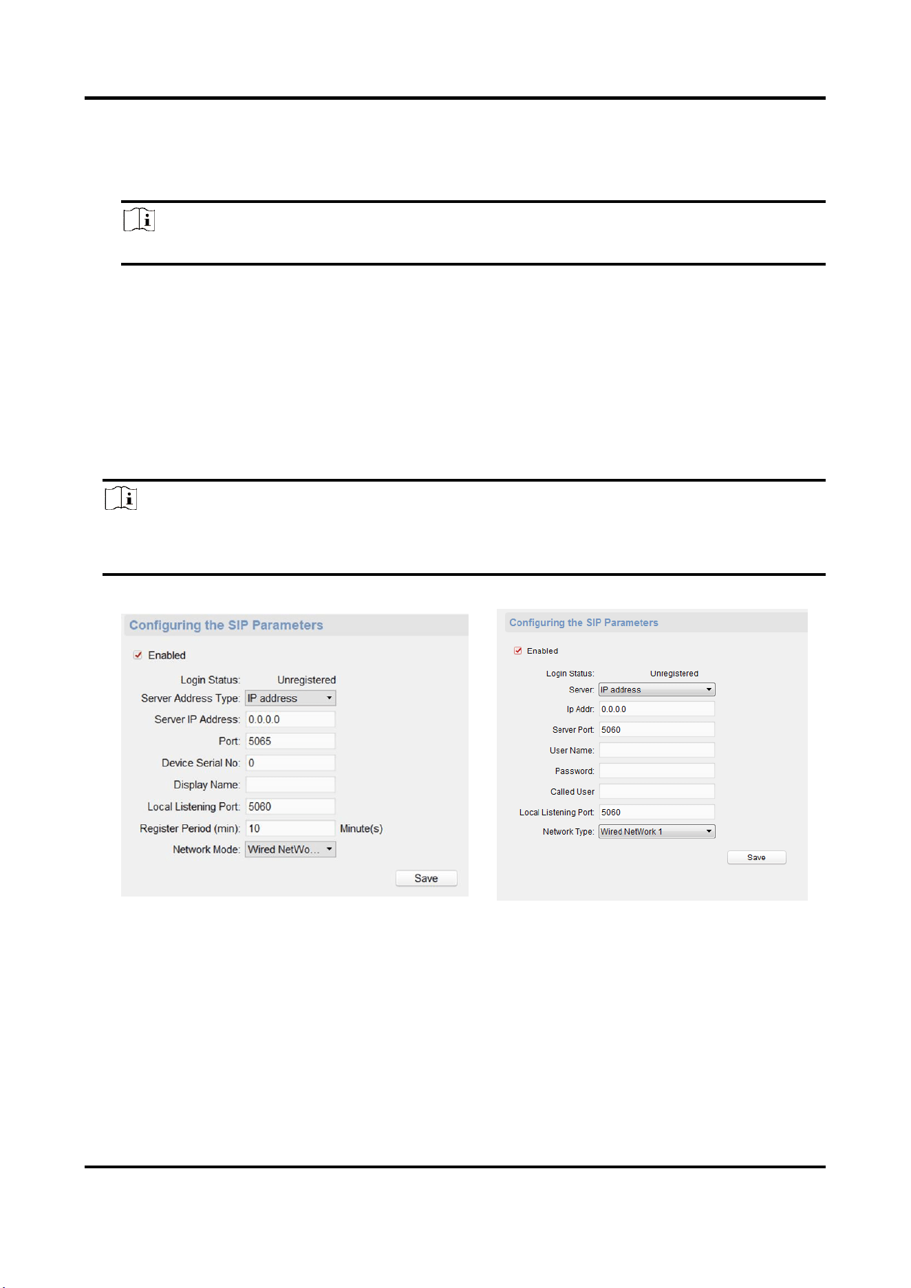
3.2.5 Set SIP
After the SIP server address is set, the device actively registers to the SIP server, and devices under
the same SIP server address can communicate with each other.
Steps
1. On the Remote Configuration page, go to Network → SIP Settings.
Note
The SIP parameters need to be configured will vary as the selected intercom protocol type. For
intercom protocol settings, please see 3.2.11Set Intercom Parameters.
Figure 3-6 SIP Setting Page (Private Protocol)
Figure 3-7 SIP Setting Page (SIP Protocol)
Login Status
Display the status of the device registers to the SIP server.
2. Select the Server Address Type as IP Address or Domain Name.
3. According to the selected address type, enter the IP address or domain name of the SIP server.
4. Set the Port and the Local Listening Port.

Panic Alarm Station Configuration Guide
12
Port
The SIP server port. By default, the private SIP port is 5065 and the standard SIP port is 5060.
The available server port number should be between 1024 and 65535.
Local Listening Port
The local port of the device SIP function. By default, the local listening port is 5060. The
available port number should be between 1024 and 65535.
5. Configure the SIP parameters according to the selected intercom protocol.
– If configuring the SIP parameters based on Private Protocol, please set the Device Serial No.,
Display Name, Local Listening Port Register Period (min) and Network Mode.
If configuring the SIP parameters based on SIP Protocol, please enter the User Name, Password
and Called User.
Device Serial No.
Device ID is the unique identification of the device, facilitating the communication between
the devices.
Display Name
You can enter the position information of the device for easy management.
Register Period (min)
The interval that the device continuously registers to the SIP server, the register period
ranges from 1 to 30 (min).
Network Mode
Select the Network Mode as Wired Network 1, Wired Network 2 or Wireless Network.
Note
When you select a wired network, the wired network is used regardless of whether the wired
network is normal; when you select a wireless network, only the wireless network is used.
User Name
The user name which the device registers to the SIP server.
Password
The password which the device registers to the SIP server.
Called User
The user name of the user which the device calls.
6. Click Save.
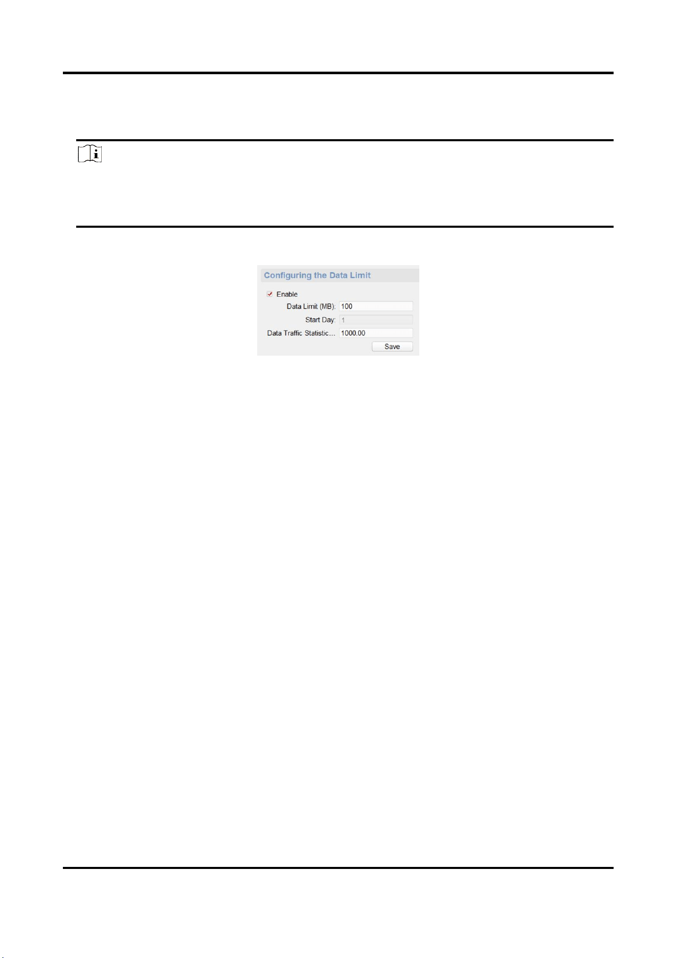
3.2.6 Data Limit
Enable the data limit for the 3G/4G wireless network. Once the data traffic exceeds the set
threshold, the data traffic excess alarm is uploaded to the platform and the user will receive a
Panic Alarm Station Configuration Guide
13
message prompt.
Steps
Note
● The data traffic will be calculated form the first day per month.
● The message prompt should be enabled, please see Set Wireless Dialing to enable the
function.
1. On the Remote Configuration page, go to Network → Data Limit.
Figure 3-8 Data Limit Configuration Page
2. Check Enable to enable the data limit.
3. Set the data limit parameters.
Data Limit (MB)
The threshold of the data traffic.
Start Day
By default, it is 1, that is, the data traffic is calculated form the first day per month.
Data Traffic Statistics (MB)
The total data traffic from the first day to today of the month.
4. Click Save.
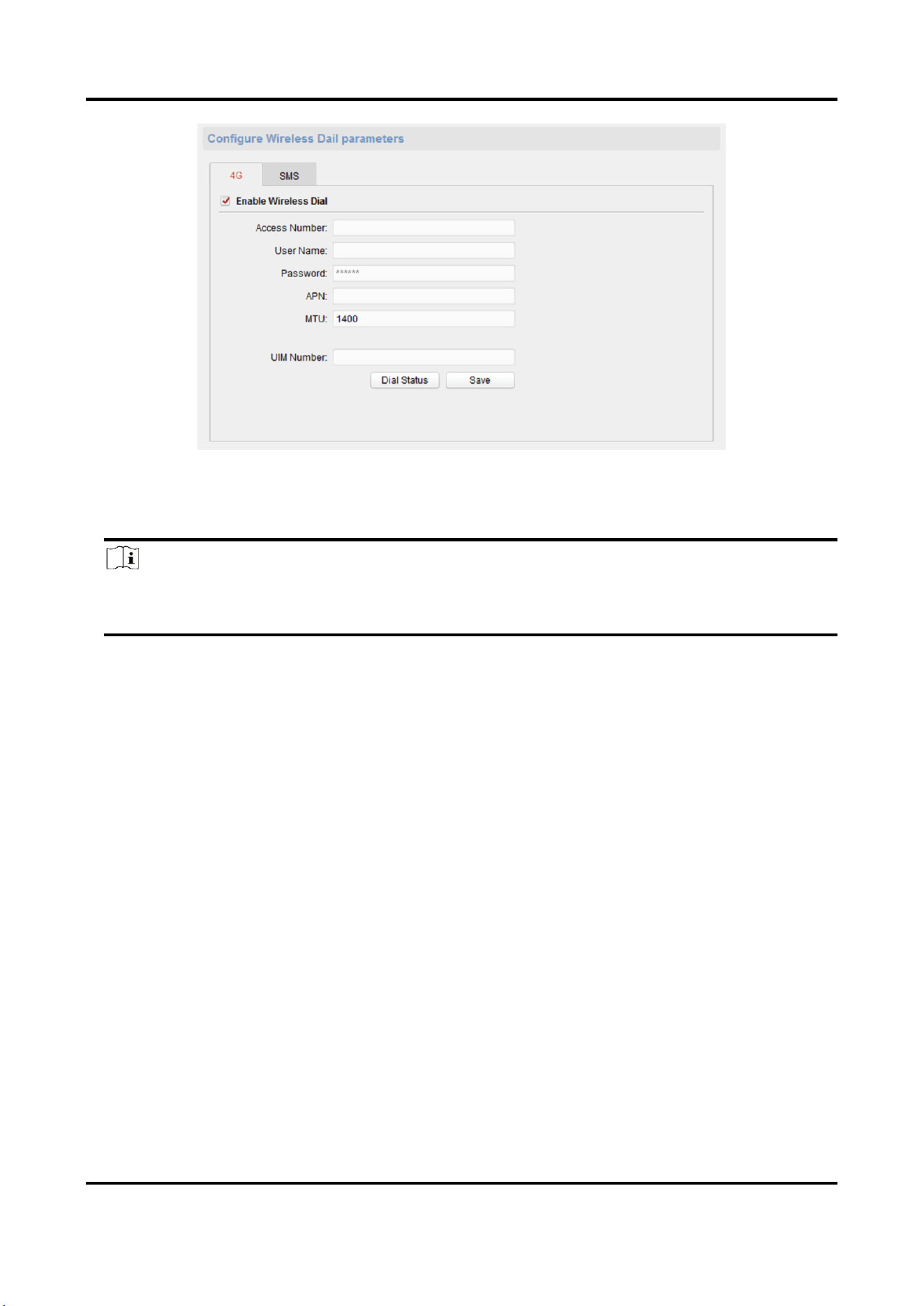
3.2.7 Set Wireless Dialing
Enable the wireless dial function, and you can use the wireless network for data/image
transmission.
Before You Start
Connect the wireless communication module to the device.
Steps
1. On the Remote Configuration page, go to Network → Wireless Dialing Settings.
Panic Alarm Station Configuration Guide
14
Figure 3-9 Data Limit
2. Click 4G and check Enable Wireless Dial to enable the wireless dial.
3. Set the Access Number, User Name, Password, APN and MTU.
Note
You can also leave these parameters blank, and the device will adopt the default settings for
dialing after other parameters are configured.
4. Enter the UIM Number.
5. Click Dial Status to view the dial status, including Real-time Mode, UIM Status, Signal Quality,
etc.
6. Click Save.
7. Optional: Enable the message prompt function.
1) Click SMS.
2) Check Enable SMS Alarm.
3) Set the mobile phone number and click Edit Permission to edit the permission of this mobile
phone number.
Smart Event
When smart event is triggered, the mobile phone number will receive an alarm message.
Data Traffic
When the wireless network traffic is excessive, the mobile phone number will receive an
alarm message.
Panic Alarm Station Configuration Guide
15
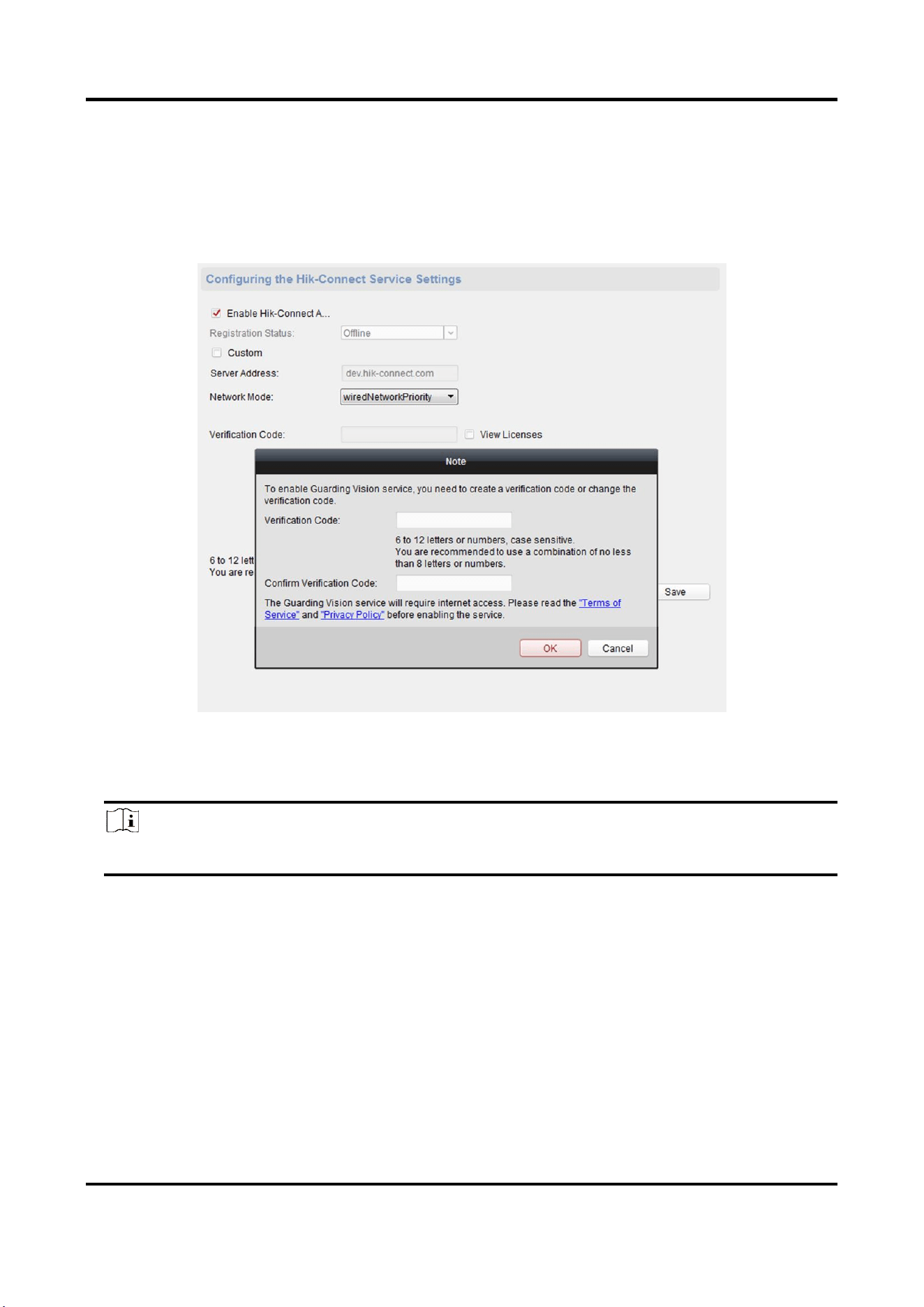
3.2.8 Set Hik-Connect
Enable Hik-Connect service and you can add the device to Hik-Connect.
Steps
1. On the Remote Configuration page, go to Network → Hik-Connect Service Settings.
Figure 3-10 Hik-Connect Service Setting Page
2. Check Enable Hik-Connect Access and enter the verification code to enable Hik-Connect service.
3. Optional: If you want to edit Server Address, check Custom and enter the server address.
Note
The default server address is dev.hik-connect.com.
4. Select Network Mode.
5. Enter a verification code and click Generate QR code.
There will be a QR code displaying on the page.
6. Click Save.
7. Scan the QR code via Hik-Connect and the device will be added to Hik-Connect.
Panic Alarm Station Configuration Guide
16
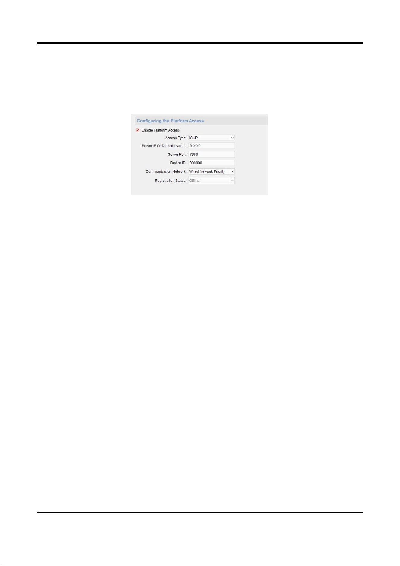
3.2.9 Access the Platform
Platform access provides you an option to manage the devices via platform.
Steps
1. On the Remote Configuration page, go to Network → Platform Access.
Figure 3-11 Platform Access Configuration
2. Check Enable Platform Access to enable the Platform Access function.
3. Set the platform access parameters.
Access Type
Select the platform to be accessed.
Server IP or Domain Name
Enter the IP address or domain name of the platform.
Server Port
Enter the port number of the platform.
Device ID
Device ID is the unique identification of the device.
Communication Network
Select the network mode for communication with platform.
Registration Status
Display the status which the device registers to the platform.
4. Click Save, and you can access to the device via platform.
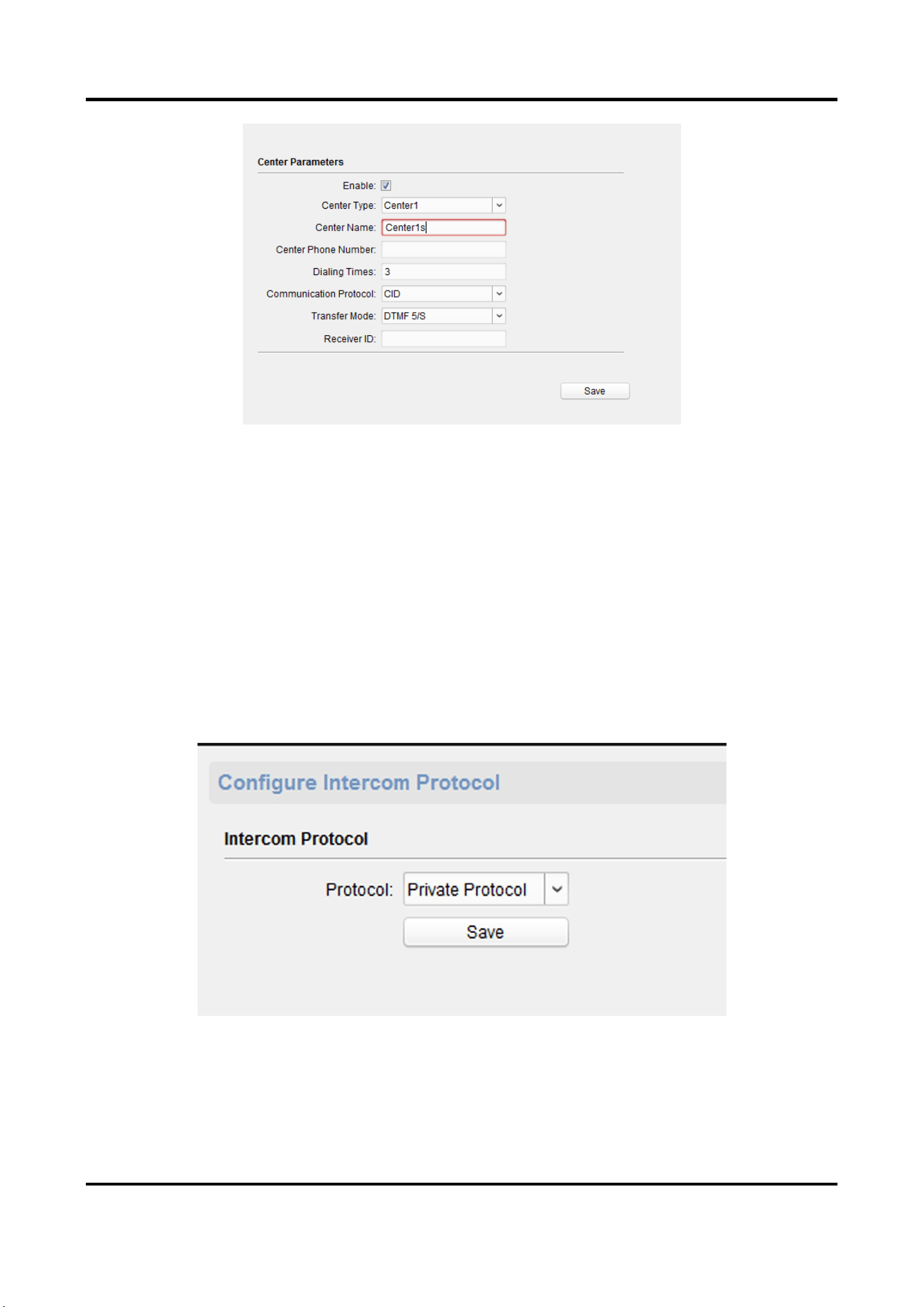
3.2.10 Set Call Center Parameters
Steps
1. On the Remote Configuration page, go to Network →Configure call center parameters.
Panic Alarm Station Configuration Guide
17
Figure 3-12 Set Call Center Parameters
2. Check to enable the function
3. Set call center parameters including center type, center name, phone number, dialing times,
communication protocol, transfer mode, and receiver ID.
3. Click Save.
3.2.11Set Intercom Parameters
Steps
1. On the Remote Configuration page, go to Network → Intercom Protocol.
Figure 3-12 Intercom Parameters Configuration
2. Select the Protocol as SIP Protocol or Private Protocol.
3. Click Save.
The device will reboot automatically after switching the protocol successfully.
Panic Alarm Station Configuration Guide
18
3.3 Alarm Settings
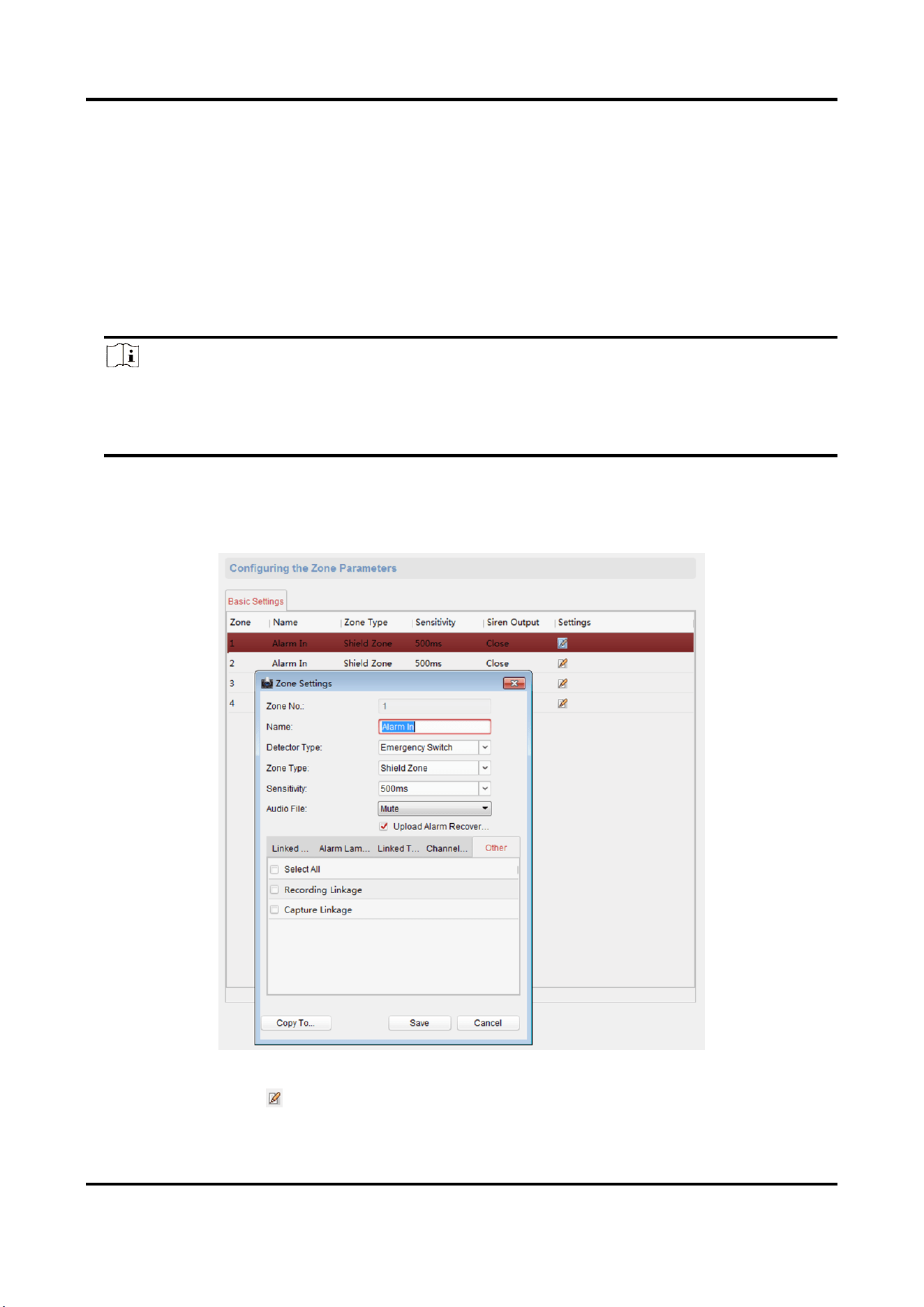
3.3.1 Set Zone
The device supports four alarm input zones and two default zones (emergency call help and
consulting). You need to configure zone parameters.
Steps
Note
The default zone has a default zone type, default audio file, and the default zone will
automatically upload an alarm recovery report. These three parameters (Zone Type, Audio File
and Upload Alarm Recovery Report) do not need to be set.
1. In the client software, go to Control Panel → Device Management, select the device in the
device list, and click Remote Configuration.
2. Go to Input → Zone.
Figure 3-13 Zone Configuration Page
3. Select an zone, click .
Panic Alarm Station Configuration Guide
19
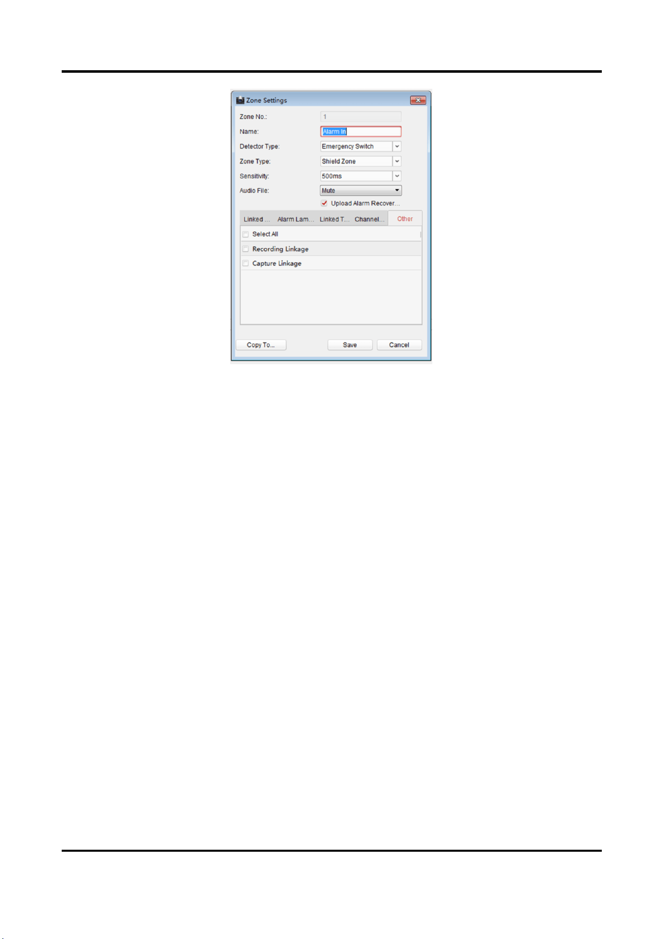
Figure 3-14 Set Zone Parameters
4. Set zone parameters.
Name
Zone name.
Detector Type
The detector type of the zone.
Zone Type
Four zone type can be set for Non-default zones: Instant Zone, Fire Zone, 24-hour Non-voiced
Zone, Shield Zone.
Instant Zone
In the armed state, as long as the detector connected to the zone is triggered, an alarm is
generated immediately without delay.
Fire Zone
The fire zone must be set to a 24-hour alarm zone. When the fire zone is triggered, start
the external siren/sounder.
24-hour Non-voiced Zone
The detector working in 24-hour non-voiced zone is in an alert state for 24 hours, and will
not be affected by the disarming operation. Once triggered, the information is immediately
uploaded to the center with no alarm sound.
Shield Zone
No events will trigger an alarm.
Sensitivity

Panic Alarm Station Configuration Guide
20
The default value is 500 ms.
Audio File
Select an audio file for zone.
Upload Alarm Recovery Report
If check Upload Alarm Recovery Report, the report will be uploaded to the center when the
alarm is restored.
5. Select the zone linkage.
Linked Siren
After the zone is triggered, the selected siren sounds.
Alarm Lamp
After the zone is triggered, the selected alarm lamp is on.
Linked Relay
After the zone is triggered, the selected trigger outputs.
Note
The relay output can set the output delay time, that is, when the zone
is triggered, the trigger outputs a signal, and the trigger will turn off
the output after the output delay time ends. Please refer to the user
manual for the output delay time setting.
Channel
After the zone is triggered, the selected video channel is linked.
Other
You can select Recording Linkage and FTP Linkage.
RRecording Linkage
After the zone is triggered, the event video is recorded.
FFTP Linkage
After the zone is triggered, the event image is captured.
6. Optional: Click Copy to..., copy the zone parameter configuration to other zones.
7. Click Save.
3.3.2 Set Relay
Configure the relay parameters, include the relay name and the output delays.
Steps
1. On the Remote Configuration page, go to Output Settings → Relay.
2. Select a relay and click , set the relay parameters.
Panic Alarm Station Configuration Guide
21
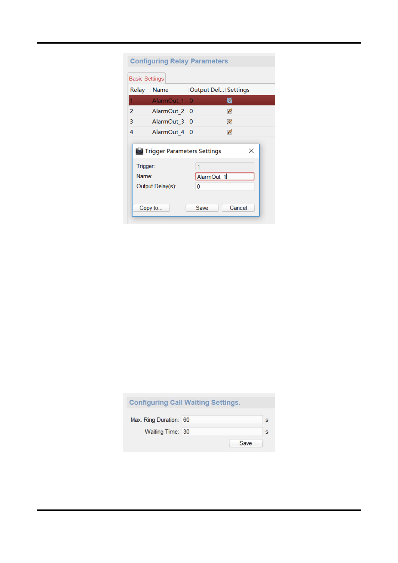
Figure 3-15 Relay Configuration Page
Name
The relay name.
Output Delay(s)
The output delay time, can be set from 0 to 2000s. After the zone event is triggered, the relay
will turn off the relay output after the output delay time is ended.
3. Click Save.
4. Optional: Click Copy to..., you can copy the relay settings to other relays.
3.3.3 Set Call Waiting
Configure the call waiting parameters, include the maximum ring duration and waiting time.
Steps
1. On the Remote Configuration page, go to Output Settings → Waiting.
Figure 3-16 Call Waiting Settings Page
2. Set the call waiting parameters.
Panic Alarm Station Configuration Guide
22
Max. Ring Duration
The playback time of the calling tone when calling, can be set from 40 s to 80 s.
Waiting Time
The extended playback time of the prompt tone based on the maximum ring time when
calling the master station and pressing the call waiting button, can b set from 10 seconds to
60 s.
3. Click Save.
3.3.4 Set Voice Prompt
Steps
1. On the Remote Configuration page, go to Output Settings → Voice Prompt.
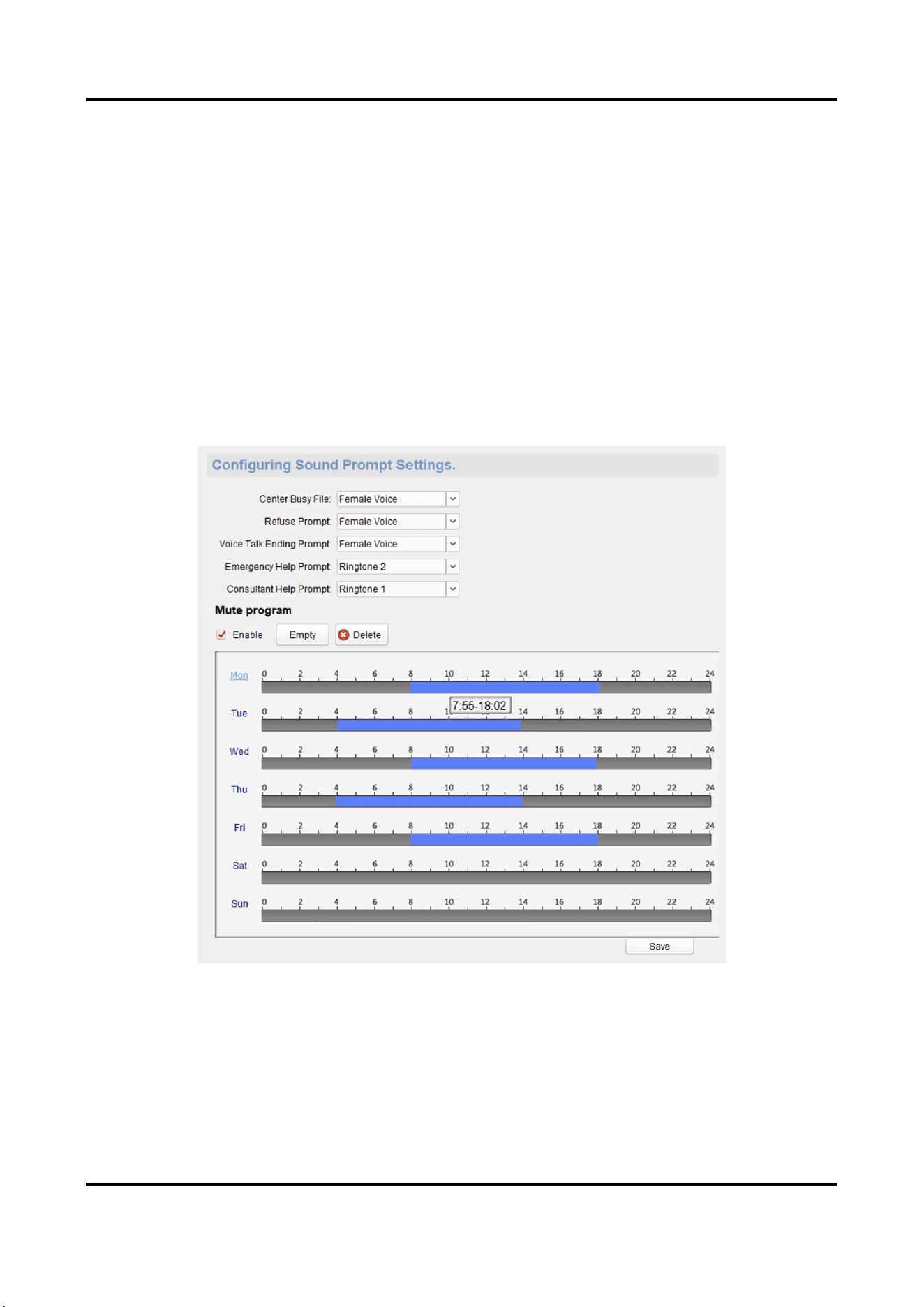
Figure 3-17 Voice Prompt Configuration Page
2. Set the Center Busy File, Refuse Prompt, Voice Talk Ending Prompt, Emergency Help Prompt,
and Consultant Help Prompt.
3. Optional: Configure the mute program.
1) Check Enable to enable the mute program.
2) Click and drag the mouse on the time bar to draw the scheduled time period.
Panic Alarm Station Configuration Guide
23
3) Optional: Edit the time period.
● Modify the time period
Click and select the added time period, drag to modify the time period position; click and
select the added time period, then moves the cursor to both ends of the time period, when
the cursor becomes a double arrow, you can drag the mouse left and right to modify the
time period.
● Delete one time period
Click and select the time period, and click Delete to delete the selected time period.
● Delete all time periods
Click Empty to delete all time periods.
The device will be muted during the configured time period.
4. Click Save.
3.4 Alarm Management
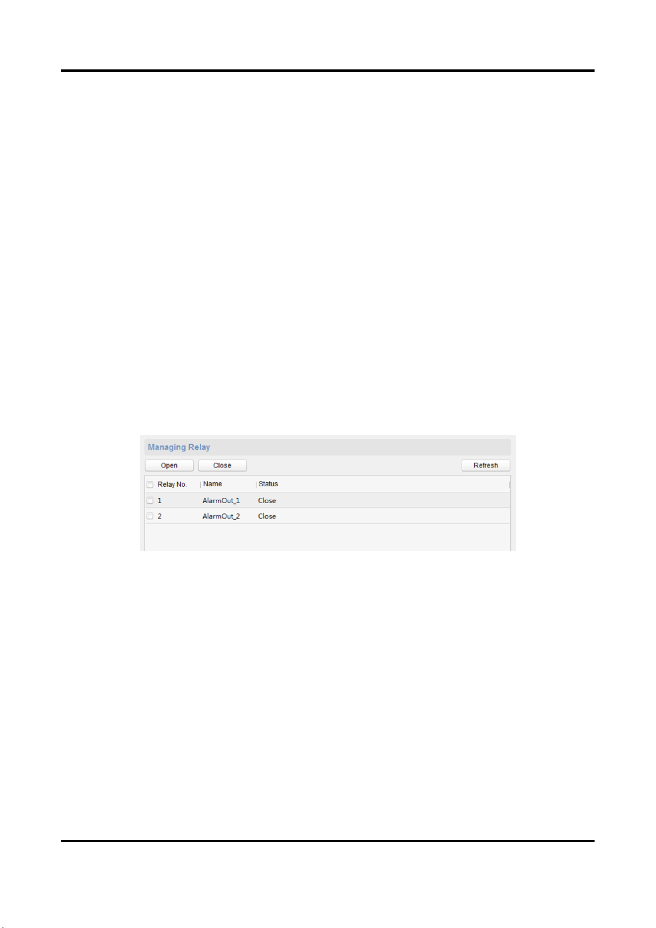
3.4.1 Manage Relay
Open or close the relay via client software.
On the Remote Configuration page, go to Alarm Management → Relay
Figure 3-18 Relay Management Page
Check the relays that need to be turned on/off. Click Open/Close to change the relay switch
status. Click Refresh, you can refresh the relay switch status.
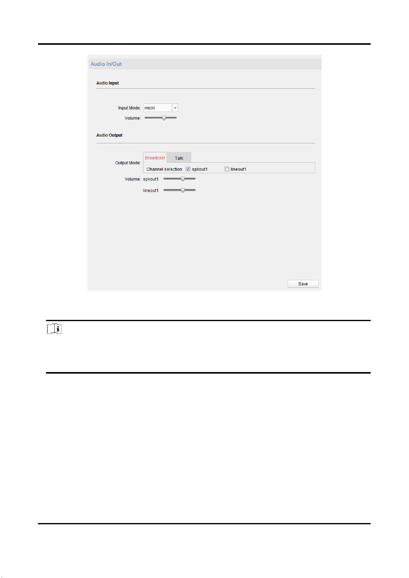
3.4.2 Manage Audio Input/Output
Configure the audio input/audio output mode and the volume of the corresponding mode.
Steps
1. On the Remote Configuration page, go to Alarm Management → Audio In/Out.
Panic Alarm Station Configuration Guide
24
Figure 3-19 Alarm Input/Output Configuration Page
2. Set the audio input/output mode and volume.
Note
● spkOut is the device's own audio input/output. lineOut1 are 3.5mm hole interfaces, which
can connect to the external microphones and speakers. The device defaults to micIn and
spkOut.
3. Click Save.
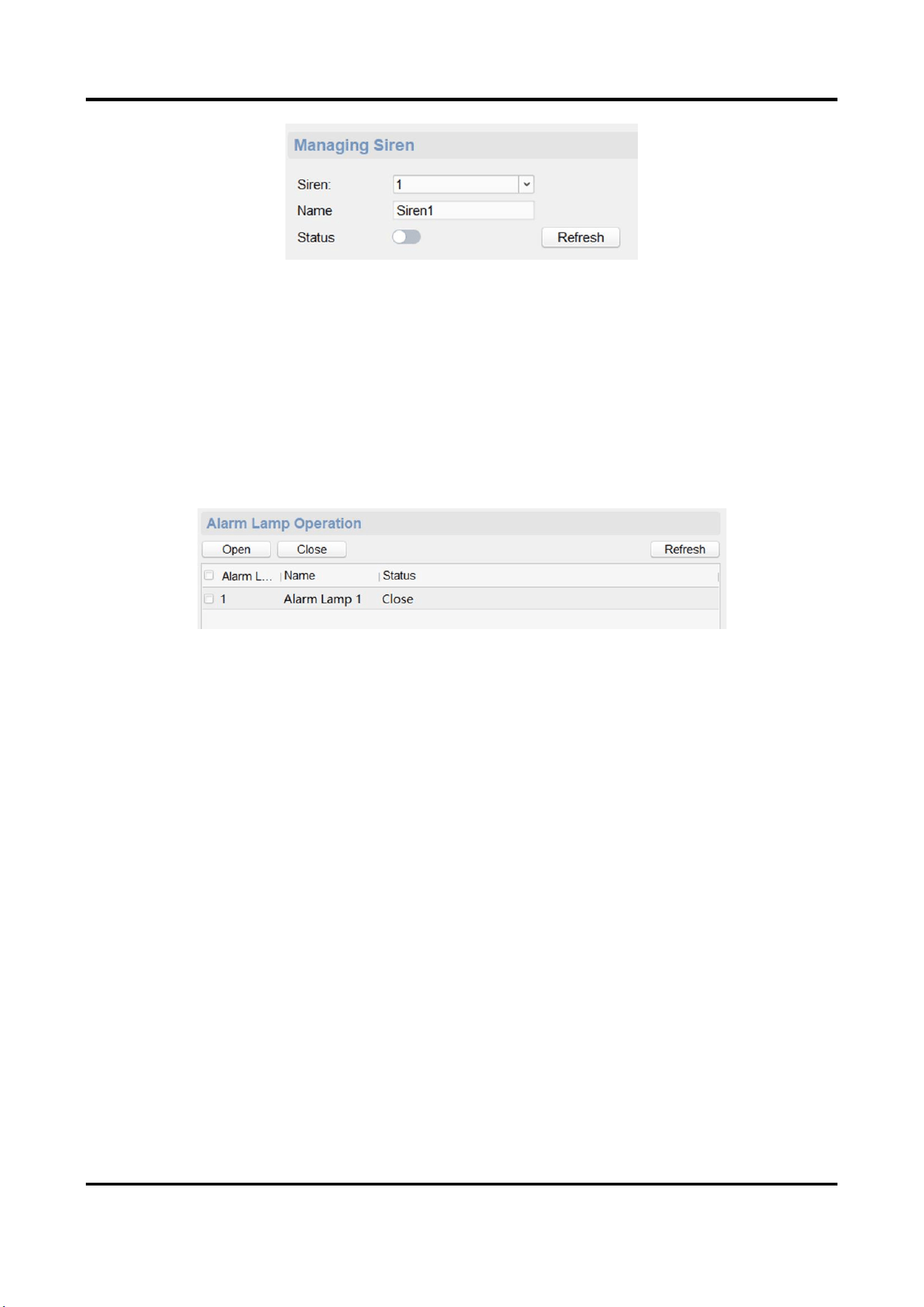
3.4.3 Manage Siren
Open/Close the siren via the client software.
Steps
1. On the Remote Configuration page, go to Alarm Management → Siren.
Panic Alarm Station Configuration Guide
25
Figure 3-20 Siren Management Page
2. Select a siren and enable Status to open the siren, or disable Status to close the siren.
3. Optional: Click Refresh to refresh the siren status.
3.4.4 Manage Strobe Light
Open/Close the strobe lamp via the client software.
Steps
1. On the Remote Configuration page, go to Alarm Management → Strobe Light.
Figure 3-21 Strobe Light Management Page
2. Check the strobe light in the list, and click Open/Close to open or close the selected strobe light.
3. Optional: Click Refresh to refresh the strobe light status.
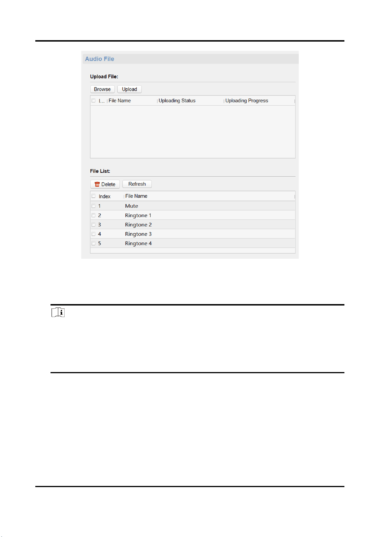
3.4.5 Manage Audio File
Upload the custom audio files to SD card, and delete the audio file in the SD card.
Before You Start
Insert the SD card into the device.
Steps
1. On the Remote Configuration page, go to Alarm Management → Audio File.
Panic Alarm Station Configuration Guide
26
Figure 3-22 Audio File Management
2. Upload the custom audio files.
1) Click Browse to select the audio file (can be selected in batch).
2) Check the audio file in the Upload File list and click Upload.
Note
● Supported Audio file format: .mp3 and .wav (8 kHz, 16 bit, and single track). The file name
can't contain spaces at the beginning and end. The length of the file name should be not more
than 31, and the file name can not contain symbols: ?\/*”<>|.
● Each audio file size up to 2MB, and up to 16 audio files are uploaded.
● An audio file will be overwritten if uploading an audio file with the same name.
3. Optional: Delete the audio files in the SD card.
1) In the File List, click Refresh to display the audio files.
2) Check the audio file needs to be deleted, click Delete.
The function using the deleted audio files will restore the default audio file configuration.
Panic Alarm Station Configuration Guide
27
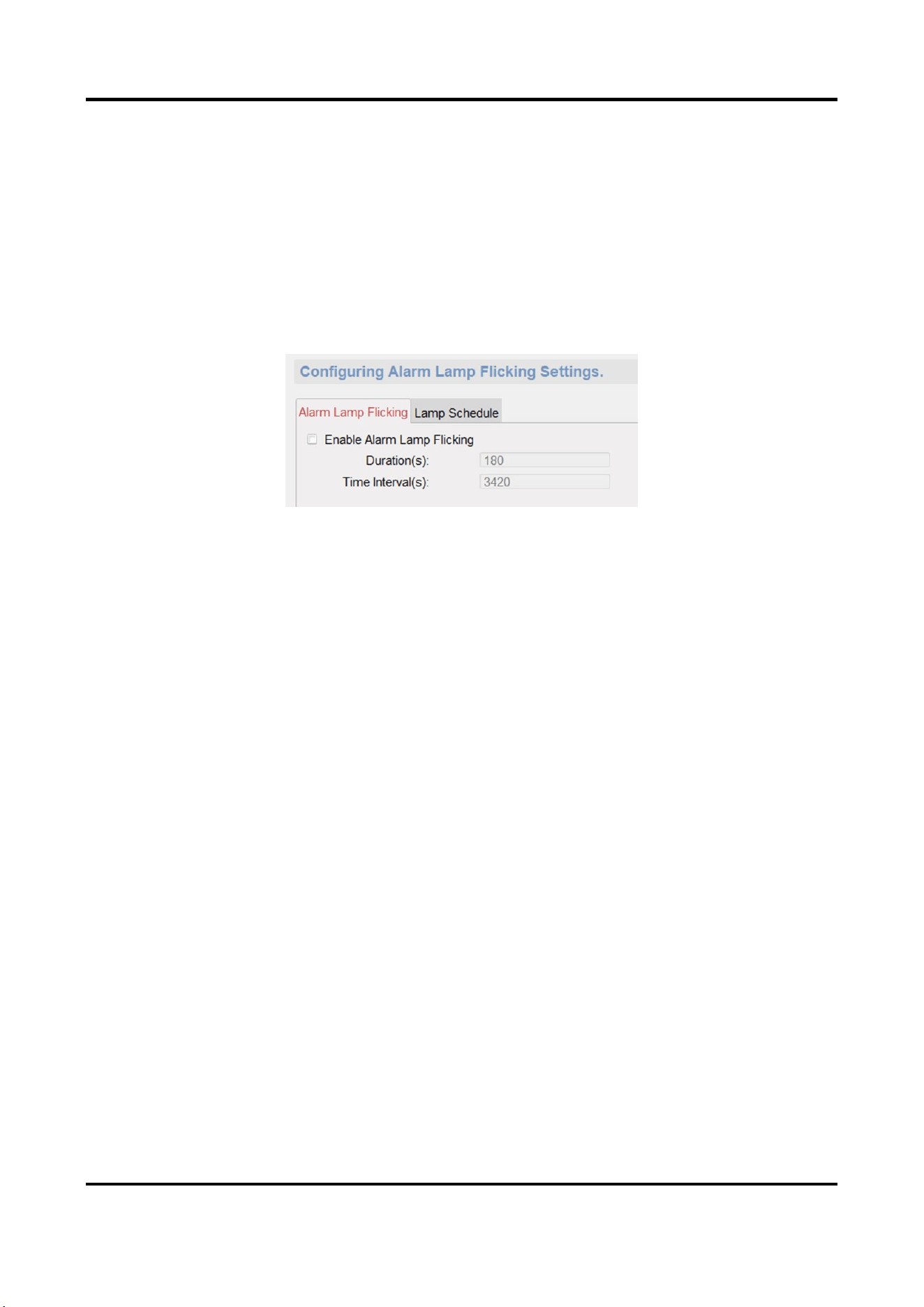
3.4.6 Manage Strobe Light Flicking
Enable the strobe light flicking, and you can configure the strobe light flicking schedule.
Steps
1. On the Remote Configuration page, go to Alarm Management → Alarm Lamp Flicking.
2. You can enable the strobe light flicking or configure the schedule.
– Enable the strobe light flicking
Click Alarm Lamp Flicking. Check Enable Alarm Lamp Flicking to enable flicking, and set the
duration and interval of the strobe light flicking.
Figure 3-24 Strobe Light Flicking Page
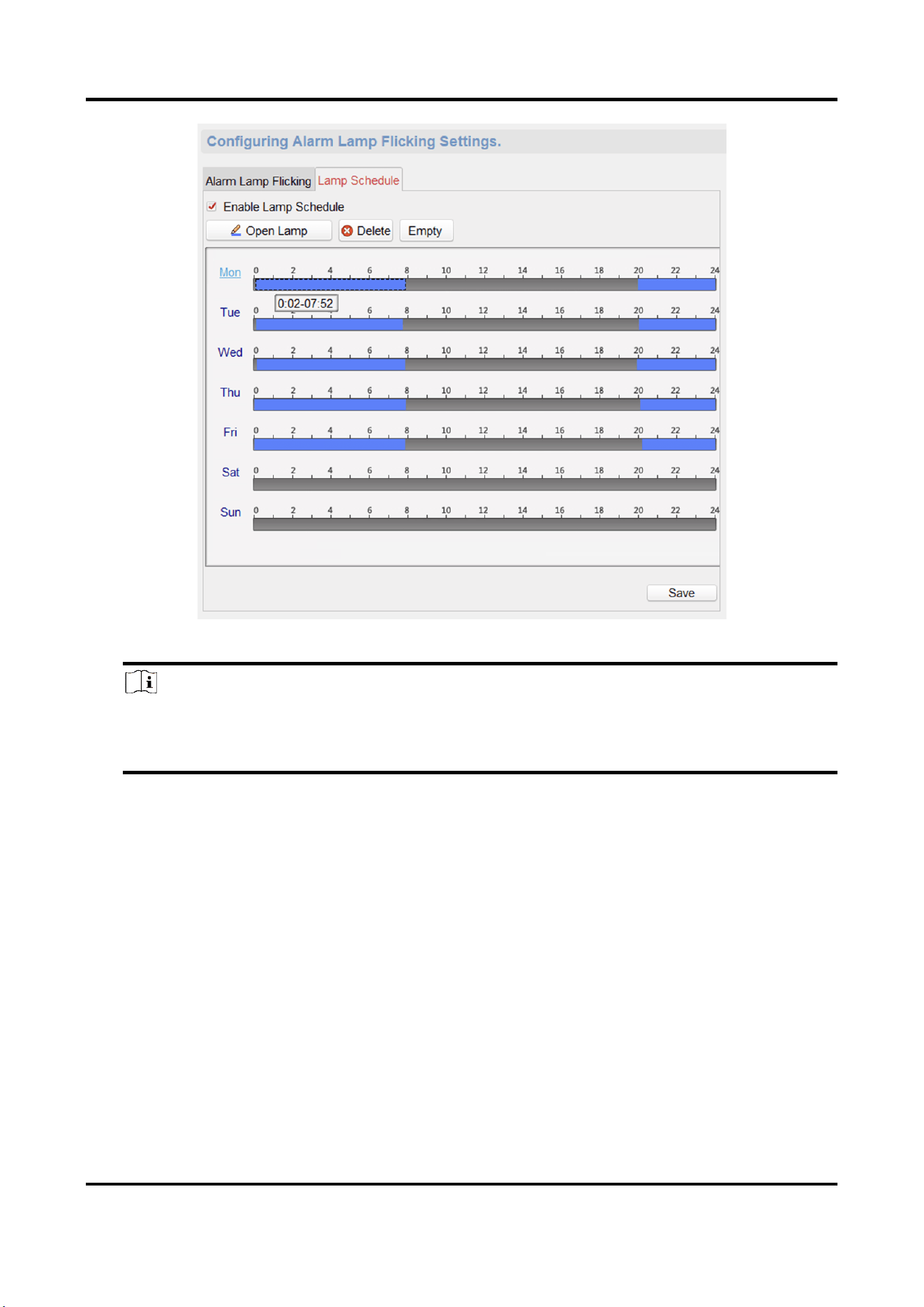
– Enable the strobe light flicking schedule
You can configure the strobe light flicking schedule for the device, and the strobe light will
flick in the scheduled time.
Click Lamp Schedule. Check Enable Lamp Schedule to enable schedule, click Open Lamp and
drag the mouse to draw the time period for opening the strobe light.
Panic Alarm Station Configuration Guide
28
Figure 3-25 Strobe Light Flicking Schedule
Note
You can delete the drawn time period.
● Select a time period, and click Delete to delete it.
● Click Empty to delete all time period.
3. Click Save.
3.5 Event Settings
3.5.1 Schedule Settings
Configure the recording and capture schedule.
On the Remote Configuration page, go to Event → Schedule.
Panic Alarm Station Configuration Guide
29
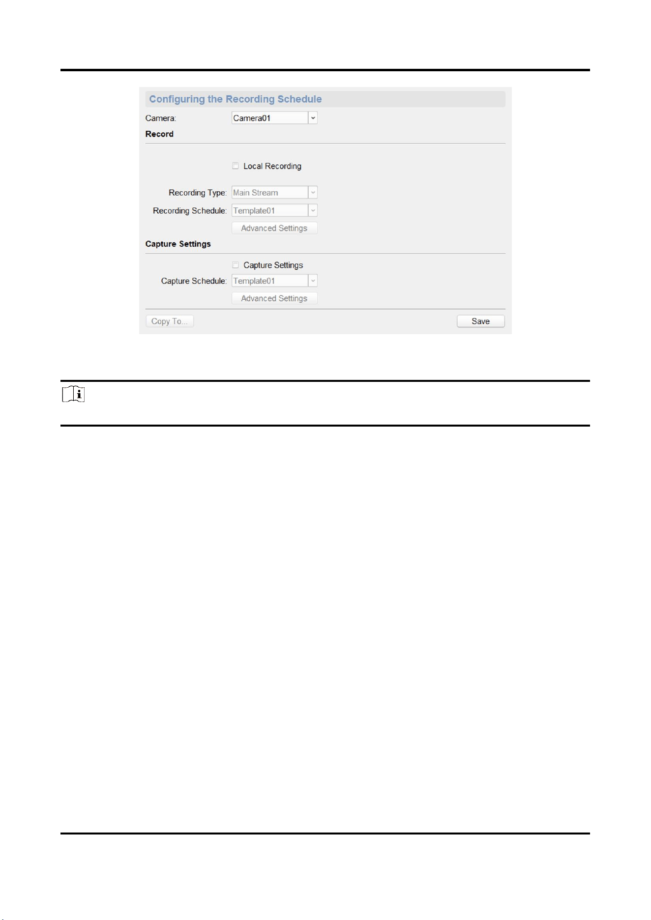
Figure 3-26 Schedule Configuration Page
Select a camera, and configure the record and capture schedule. Click Save to save the settings.
Note
The panic alarm station without camera does not support capture schedule configuration.
Record schedule configuration
Local Recording
Check Local Recording to enable the recording.
Recording Type
Main Stream and Sub Stream is optional.
Recording Schedule
Click the drop-down box of Recording Schedule, and configure the recording schedule.
There are three schedules.
● The schedule template (not editable) that comes with the system, such as all-day template,
weekday template and event template.
● Editable schedule template01 to template08. For detailed edit method, see Set System
Schedule.
● Custom schedule. For detailed edit method, see Set Custom Schedule.
Advanced Settings
Click Advanced Settings and set the pre-recording time, Post-recording time, and record audio
as needed.
Panic Alarm Station Configuration Guide
30
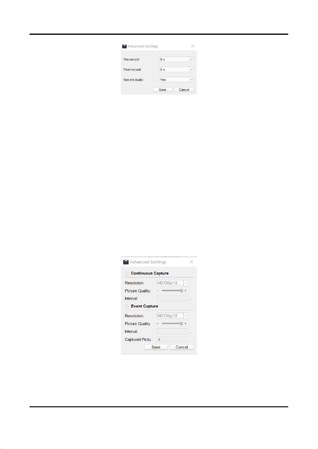
Figure 3-27 Advanced Settings of Record
Pre-record
The pre-recording time can be selected as 5 s or not pre-record.
Post-record
The delay recording time can be selected as 5 s or 10 s.
Record Audio
The record audio can be set as Yes or No. If you select Yes, record file will contain audio.
Capture schedule configuration
Capture Settings
Check Capture Settings to enable the capture schedule.
Capture Schedule
Click the drop-down box of Capture Schedule, and configure the capture schedule. The settings
of capture schedule is the same as the settings of recording schedule.
Advanced Settings
Click Advanced Settings and configure the capture settings.
Figure 3-28 Advanced Settings of Capture
● Continuous capture configuration
Check Continuous Capture to enable the timed capture function, which can capture the
Panic Alarm Station Configuration Guide
31
image at regular intervals according to the set interval.
Resolution
Select the picture resolution. By default, it is HD720p(1280×720).
Picture Quality
Set the picture quality. The higher the value, the better the picture quality.
Interval
Timed capture based on this time interval.
● Event capture configuration
Check Event Capture to enable the event capture function, which can capture multiple
pictures when an event is triggered.
Resolution
Select the picture resolution. By default, it is HD720p(1280×720).
Picture Quality
Set the picture quality. The higher the value, the better the picture quality.
Interval
The interval between the two event captures.
Captured Picture Number
The total number of the event capture.
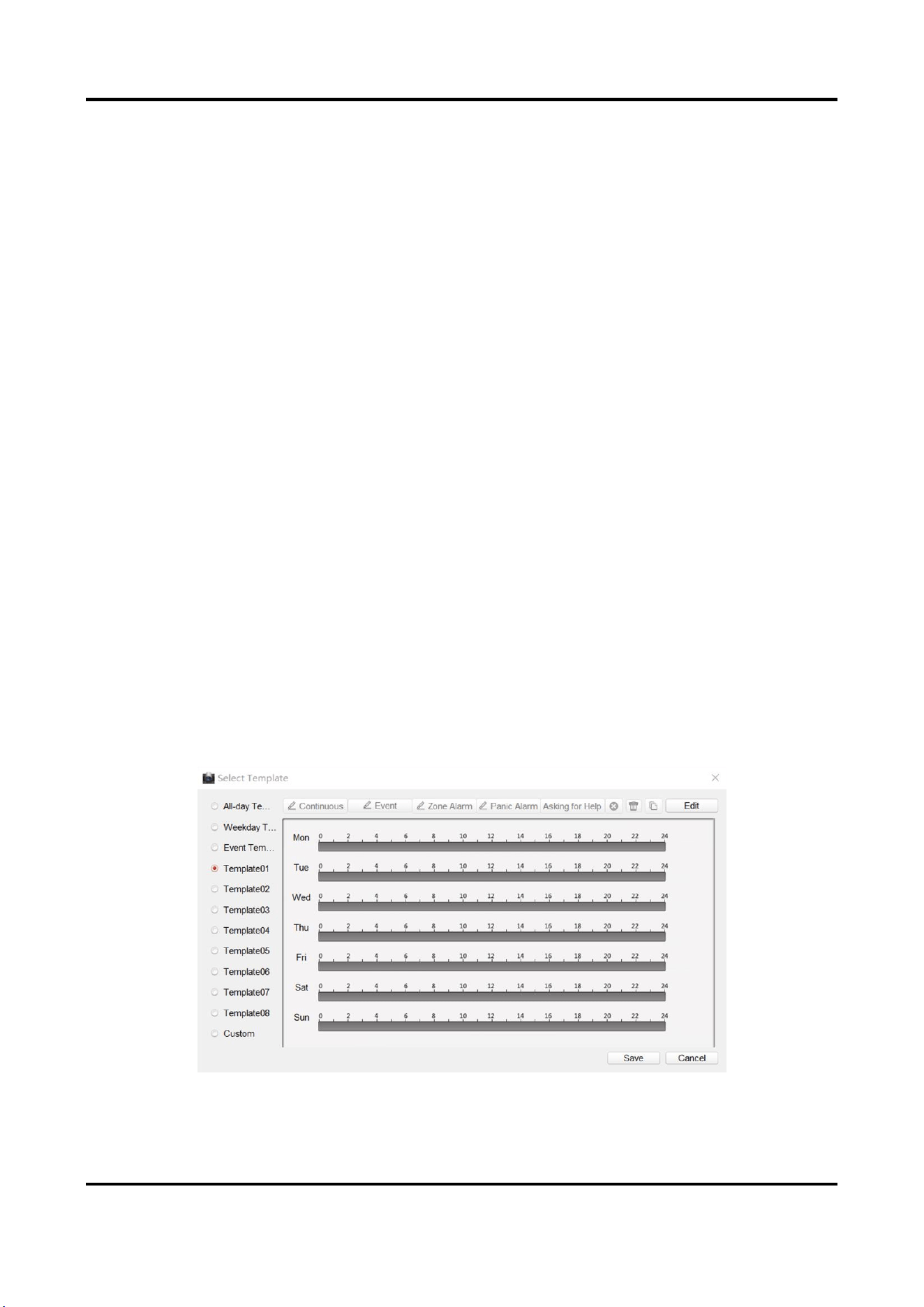
Set System Schedule
Steps
1. Select and click the text box of system editable template (Template01 to Template08).
Figure 3-29 Selection the System Template
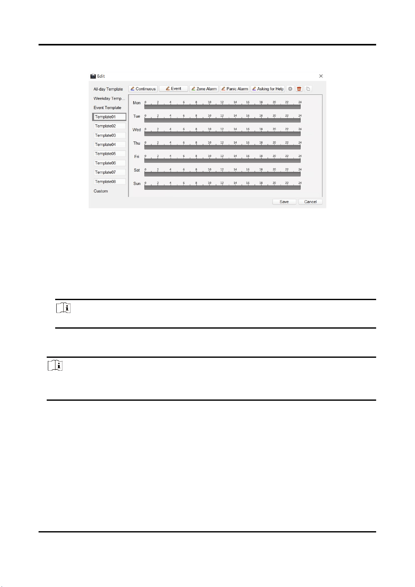
Panic Alarm Station Configuration Guide
32
2. Click Edit to go to the editing page.
Figure 3-30 System Template Editing Page
3. Optional: Select the schedule type.
– Continuous: Regardless of whether an event is triggered or not, the system records video
according to the scheduled recording time period.
– Event: The event is recorded during the scheduled recording time period when the event is
triggered.
– Zone: If an alarm occurs in the zone and the channel linkage of the zone is set, the event is
recorded during the scheduled recording time period.
Note
You can refer to Set Zone for channel linkage settings.
– Panic Alarm/ Asking for Help: The panic alarm /asking for help event is recorded during
scheduled recording time period when there is a panic alarm call for help.
Note
If the schedule template does not have the schedule type selection button, you can skip this
step.
4. Move the mouse to the time bar. When the cursor changes to a pen, click and drag the mouse
within the time bar to draw the schedule time period.
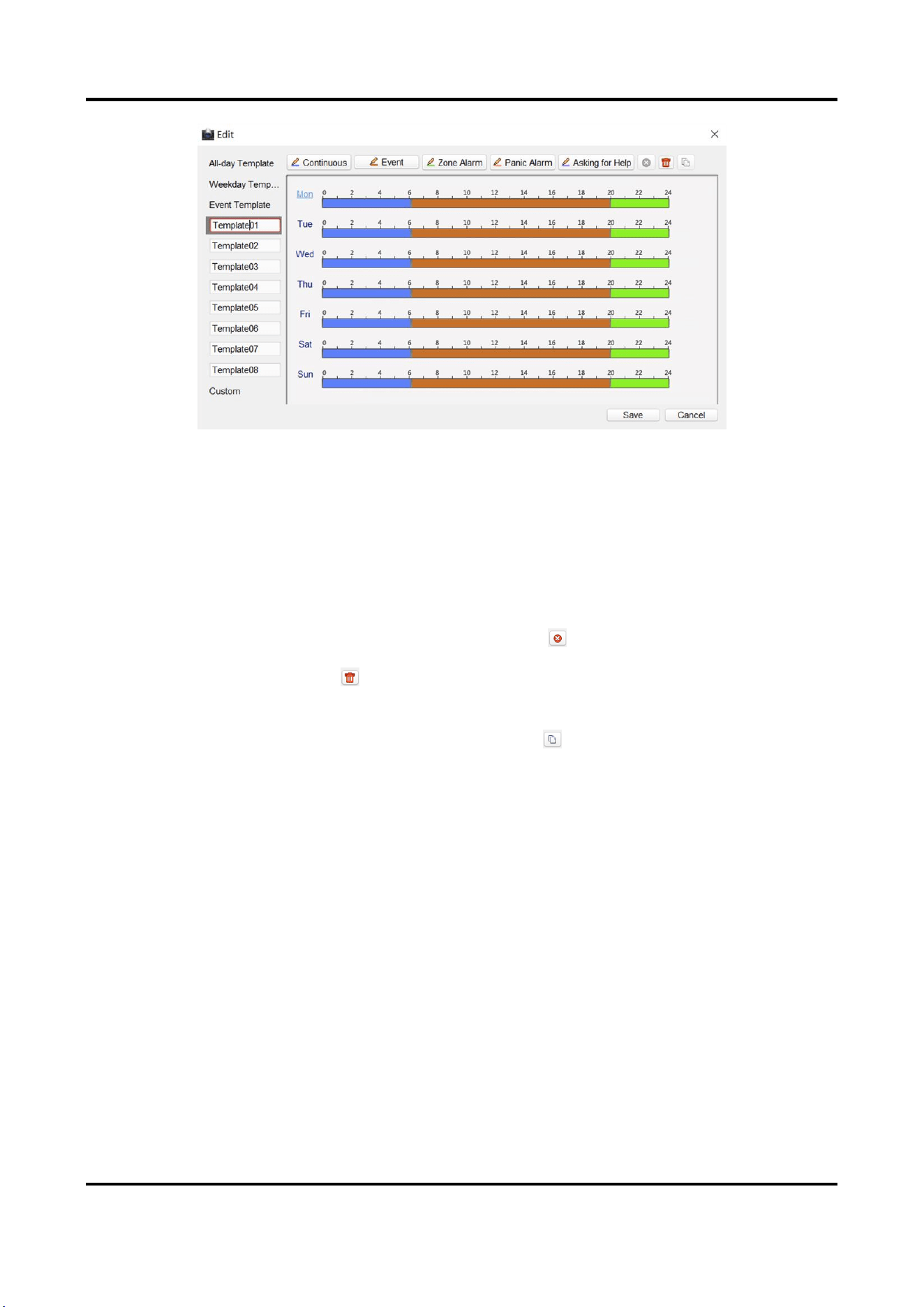
Panic Alarm Station Configuration Guide
33
Figure 3-31 Draw a schedule time period
5. Edit the schedule time period.
Modify the time
period
Move the mouse to the time period that has been drawn. When the
cursor changes to the hand, click the drag time period to modify the
time period position; move the mouse to the end of the drawn time
period, when the cursor changes to double arrow, you can drag the
mouse to modify the time period.
Delete a time period
Select the time period, and click to delete it.
Delete all time
period
Click to delete all.
Copy the time period
Select the time period and click , you can check the day and copy
the current time period to the checked day.
6. Click Save.
Set Custom Schedule
Steps
1. Check Custom to go to the custom schedule editing page.
Panic Alarm Station Configuration Guide
34
Figure 3-32 Custom Schedule Editing Page
2. Draw the schedule time period. For detailed, seeSet System Schedule.
3. Click Save.
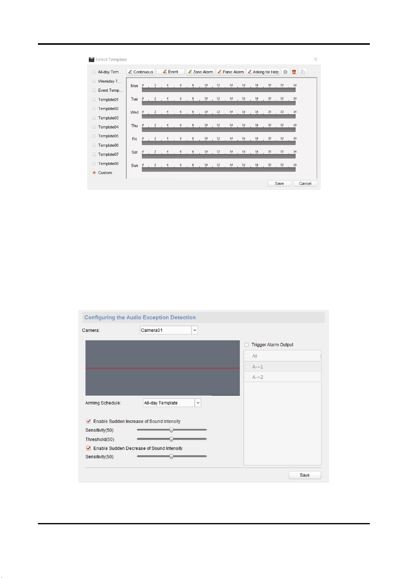
3.5.2 Set Audio Exception Detection
Audio exception detection means that when the sound in the environment is detected as sudden
increase of sound intensity or sharp decrease of sound intensity, an alarm output will be triggered.
Steps
1. On the Remote Configuration page, go to Event → Audio Exception Detection
Figure 3-33 Audio Exception Detection Configuration Page

Panic Alarm Station Configuration Guide
35
2. According to actual needs, select and check Enable Sudden Increase of Sound Intensity, Enable
Sudden Decrease of Sound Intensity. And set the parameters.
Note
Sensitivity(50) and Thresholds(50) can be set from 1 to 100 and default to 50.
3. Click the drop-down box of Arming Schedule and set the arming schedule for audio exception
detection.
Note
There are three schedules.
● The schedule template (not editable) that comes with the system, such as all-day template,
weekday template and event template.
● Editable schedule template01 to template08. For detailed edit method, see Set System
Schedule.
● Custom schedule. For detailed edit method, see Set Custom Schedule.
4. Check Trigger Alarm Output, select and check the alarm output signal that is linked when the
audio exception is detected.
5. Click Save.
Result
During the configured arming schedule, the audio anomaly event is detected according to the
enabled detection items, and the selected alarm output signal is linked when the audio exception
is detected.
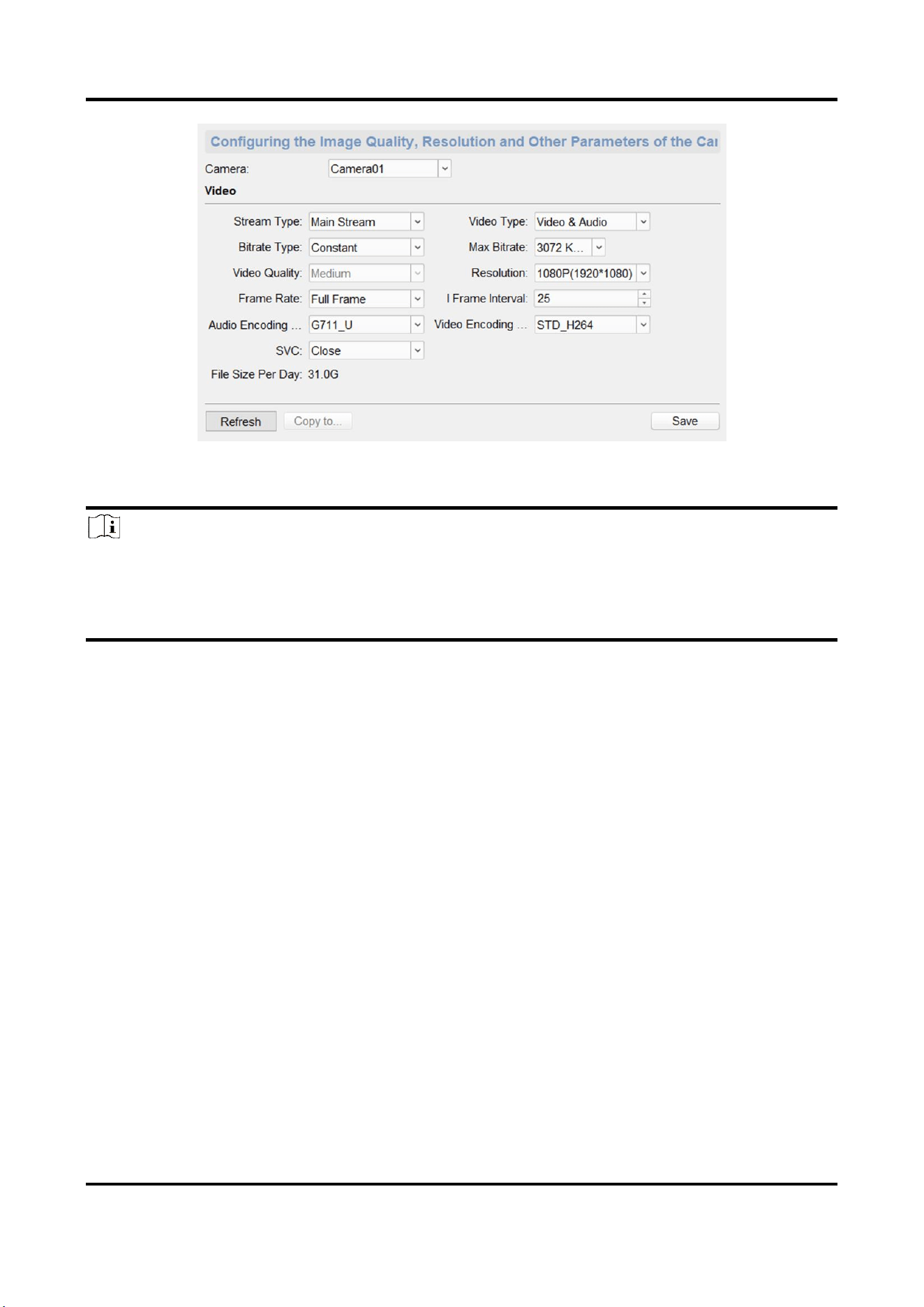
3.6 Video & Audio Settings
3.6.1 Video & Audio Settings
Configure the image quality, resolution and other parameters of the camera.
On the Remote Configuration page, click Image → Video & Audio.
Panic Alarm Station Configuration Guide
36
Figure 3-34 Video & Audio Configuration Page
Select a camera, and set the video and audio parameters. Click Save to save the settings.
Note
● You can click Copy to... to copy the parameters to other camera.
● After editing the video and audio parameters, the device won't reboot.
● Please combine the actual demand and storage capacity to configure the video and audio
parameters.
Stream Type
The stream type of camera can be set as Main Stream or Sub Stream. By default, it is Main
Stream. The main stream is used for HD storage and preview; the sub stream is used for SD
storage and preview when the network bandwidth is insufficient.
Video Type
The video type can be set as Video or Video & Audio. By default, it is Video & Audio, where
video contains sound and images. If you don't need sound, choose Video Stream.
Bitrate Type
The bitrate type can be set as Constant or Variable. By default, it is Constant, where you should
select a constant value from the Bitrate drop-down box. You are supposed to select the
maximum bitrate when the bitrate type is set as Variable.
Video Quality
You are able to choose different level of the video quality. The video quality is not optional by
default when the bitrate type is Constant.
Resolution
According to the requirements for video clarity, the higher the resolution, the higher the
bandwidth requirement for the network.

Panic Alarm Station Configuration Guide
37
Frame Rate
Video frames per second. According to the actual bandwidth setting, the higher the video frame
rate, the higher the required bandwidth and the higher the required storage space.
I Frame Interval
The number of frames between the two key frames before and after. The larger the I frame
interval is, the smaller the code stream fluctuation is, but the image quality is relatively poor.
Otherwise, the code stream fluctuation is larger and the image quality is higher. It is
recommended to use the default value.
Audio Encoding Type
When the stream type is the Main Stream, the audio encoding type can be set as G711_U,
G726, or AAC. And the audio encoding type of the sub stream is the same as the audio encoding
type set in the main stream.
Video Encoding Type
By default, it is STD_H264.
SVC
It is a scalable video coding technology. The SVC function can be used for framed video
recording to reduce storage space. The framed video file still supports normal decoding. When
the SVC function is selected to be On, both the storage device and the decoding device must be
required to support the function. When the SVC function is selected as Auto, the device will
adapt to the current network environment and decide whether to send framed video to ensure
that the image can be previewed normally.
File Size Per Day
According to the video and audio parameters, the video file size of the whole day will be
automatically calculated.
Note
● After the video and audio parameters are changed, the device won't reboot.
● Please combine the actual demand and storage capacity to configure the video and audio
parameters.
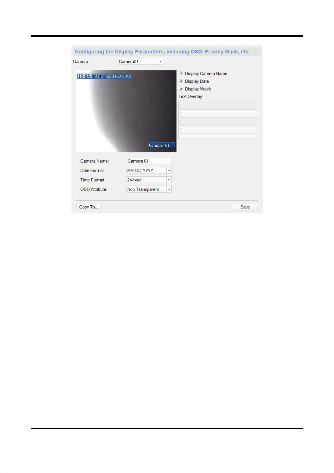
3.6.2 Set Display
Edit the display information of the camera.
On the Remote Configuration page, go to Image → Video Display.
Panic Alarm Station Configuration Guide
38
Figure 3-35 Video Display Configuration Page
Select a camera from the drop-down box to configure the display parameters of the camera,
including display position, display format and optional display content, you are able to add custom
display information.
Editing the display position
Drag the blue box on the live view page to change the position of the display information, click
Save, and then the position of the display information will be updated.
Editing the display format
Date Format
Select the display format of the date in the Date Format Drop-Down box.
Time Format
Select Time Format as 24-hour or 12-hour.
OSD Format
There are four freely combined display status to choose from depending on whether the display
information is transparent or flashing. For example, when the display status is Transparent &
Blinking, the displayed information will be displayed with a certain transparency and will flash. .
Editing the display content
You are able to select the display content optionally, edit the camera name, and add the custom
Panic Alarm Station Configuration Guide
39
display content.
● Selecting the display content
According to your requirement, check Display Camera Name, Display Date, Display Week to
display the selected display content. Click Save to save the settings.
● Editing the camera name
Editing the camera name in the Camera Name text box and click Save.
● Adding custom display content
Click the right area of the check box in the Text Overlay List and enter display content in the
text box. Check the text and click Save to display the custom information.
Note
You can drag the content to modify the location, or remove the check to cancel the display.
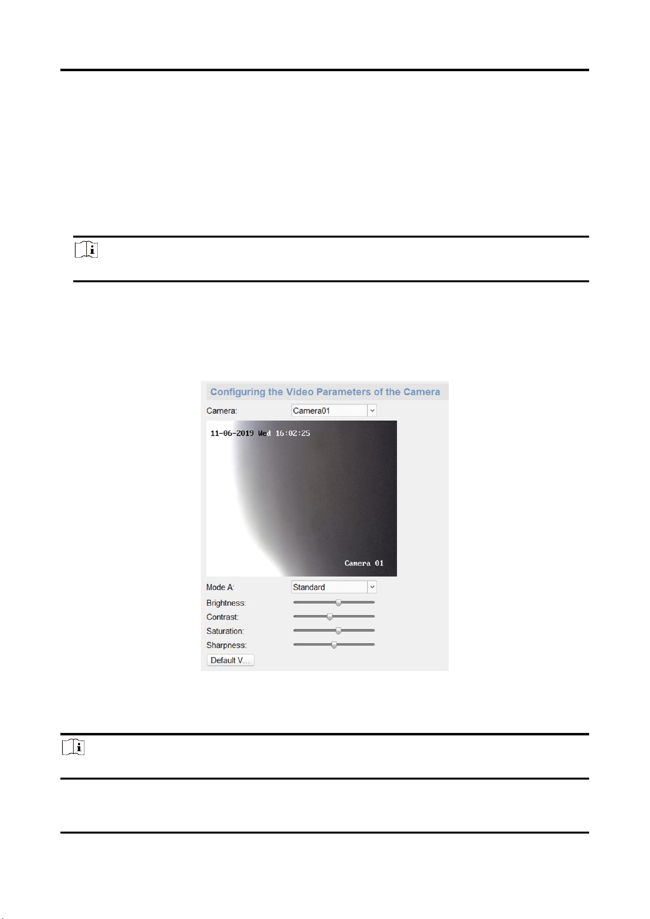
3.6.3 Set Image Parameters
For the device with camera, you can set the image parameters for camera.
On the Remote Configuration page, go to Image → Image Settings.
Figure 3-36 Image Settings Page
Select a camera to configure the video parameters, including brightness, contrast, saturation and
sharpness.
Note
● By default, the brightness is 6, the contrast is 5, the saturation is 6, the sharpness is 50.
Panic Alarm Station Configuration Guide
40
Click Default Value, you can restore all video parameters to default.
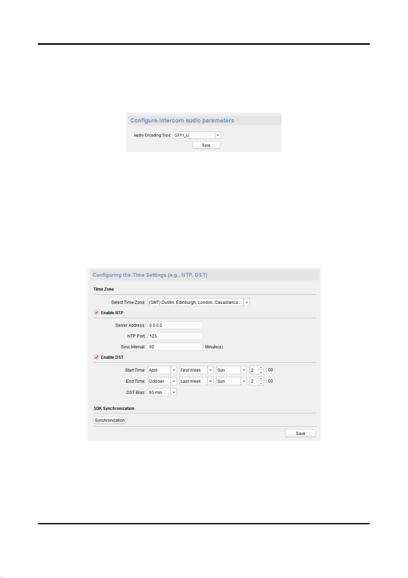
3.6.4 Set Intercom Audio
On the Remote Configuration page, go to Image → Intercom Audio.
Figure 3-37 Intercom Audio Configuration Page
Select the Audio Encoding Type as G711_U, G726, AAC, or OPUS from the drop-down box. And
click Save to save the settings.
3.7 System Settings
3.7.1 Set Time
On the Remote Configuration page, go to Device Information → Time.
You can set the time zone, NTP, DST on the Time page.
You can also click Synchronization to implement SDK synchronization.
Panic Alarm Station Configuration Guide
41
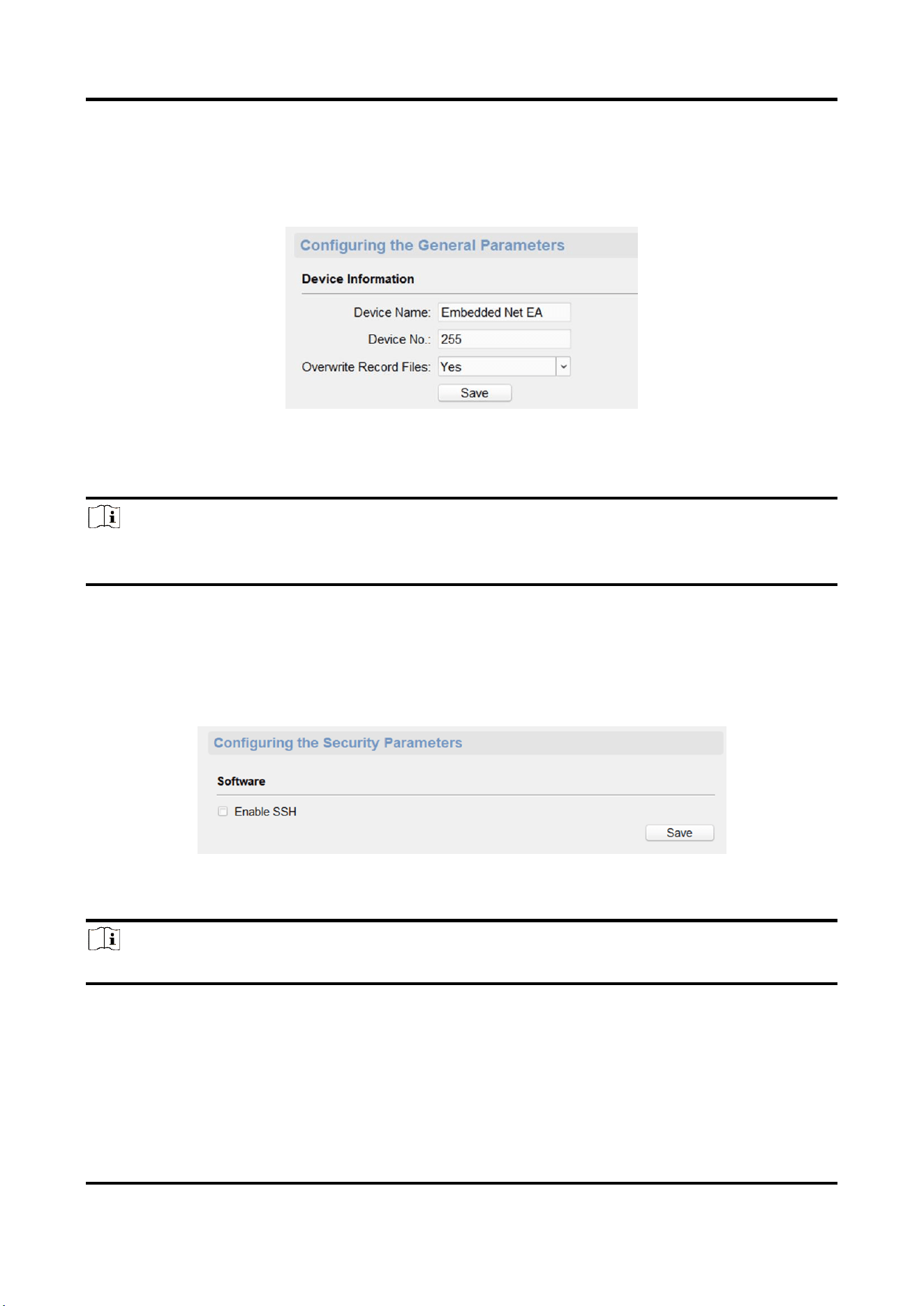
3.7.2 Set System Parameters
Set the device name, device No. and configure the video files.
On the Remote Configuration page, go to System → General Parameters.
Figure 3-38 System Parameters Setting Page
Set the device name and device No., and select Yes or No from the Overwrite Record Files drop-
down box. Click Save to save the settings.
Note
Select Overwrite Record Files as Yes, the new video file will overwrite the earliest video file when
the device storage is full.
3.7.3 Set Security
Enable/disable SSH service, which is used to provide security configuration for remote debugging.
On the Remote Configuration page, go to System → Security.
Figure 3-39 Security Parameters Configuration Page
Check Enable SSH to enable SSH service, and click Save.
Note
By default, the SSH service is not enabled. The default setting will be restored after the restart.
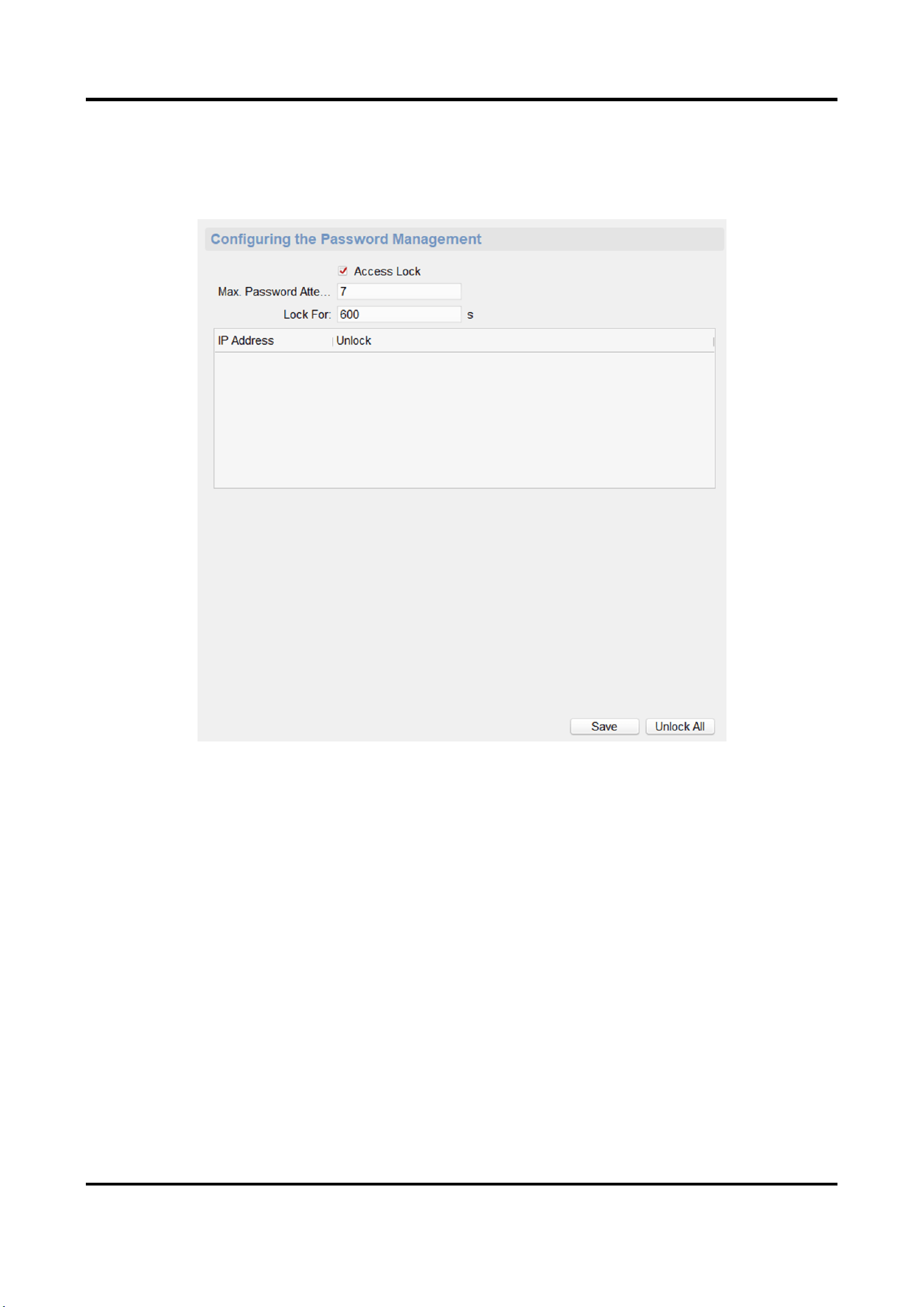
3.7.4 Set Password
Set the maximum password attempts, the lock duration of the locked user. And you can unlock the
Panic Alarm Station Configuration Guide
42
user remotely.
Steps
1. On the Remote Configuration page, go to System → Password Management.
Figure 3-40 Password Management Page
IP Address
The IP address of the terminal in which the locked user logs.
Unlock
The user's access lock status on the corresponding IP address.
2. Enable the access lock function and set the lock parameters.
1) Check Access Lock to enable the access lock function.
2) set the user lock parameters, including maximum password attempts and lock duration.
Max. Password Attempts
The maximum times that the user attempts to enter the password. By default, it is 7, the
available value is 3 to 10.
Lock For
The lock duration of the locked user. By default, it is 600 s, the available value is 10 to 3600
s.
Panic Alarm Station Configuration Guide
43
3) Click Save.
3. Optional: Click Unlock All to unlock all user.
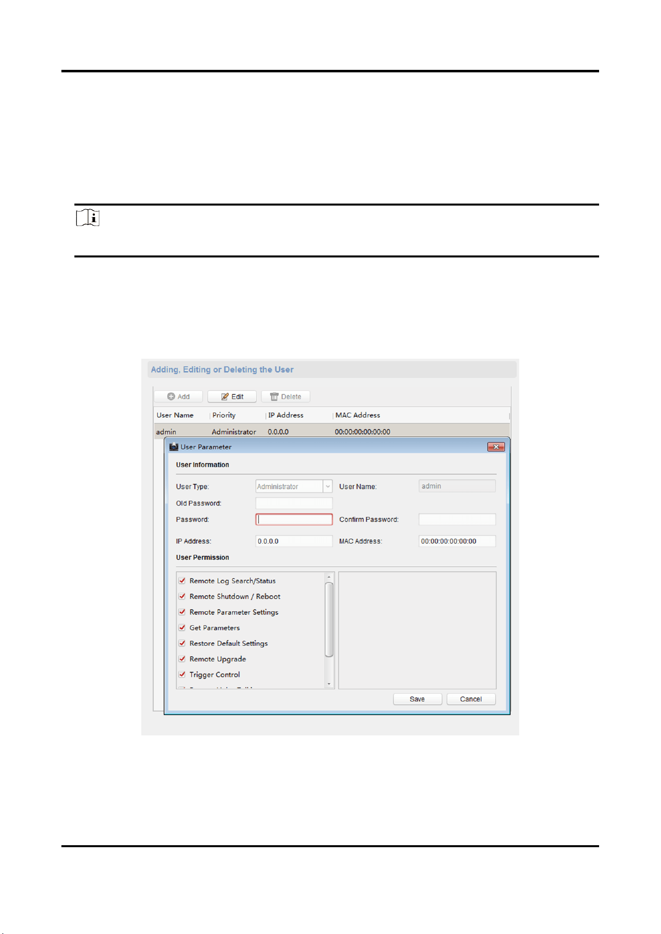
3.7.5 Set User
Steps
Note
The device only has the admin user and only supports modifying the admin user password.
1. On the Romte Configuration page, go to System → User.
2. Edit the admin user password.
1) Select the admin user and click Edit.
2) Enter the new password and confirm it.
3) Click Save.
Figure 3-41 Edit Admin User
Panic Alarm Station Configuration Guide
44
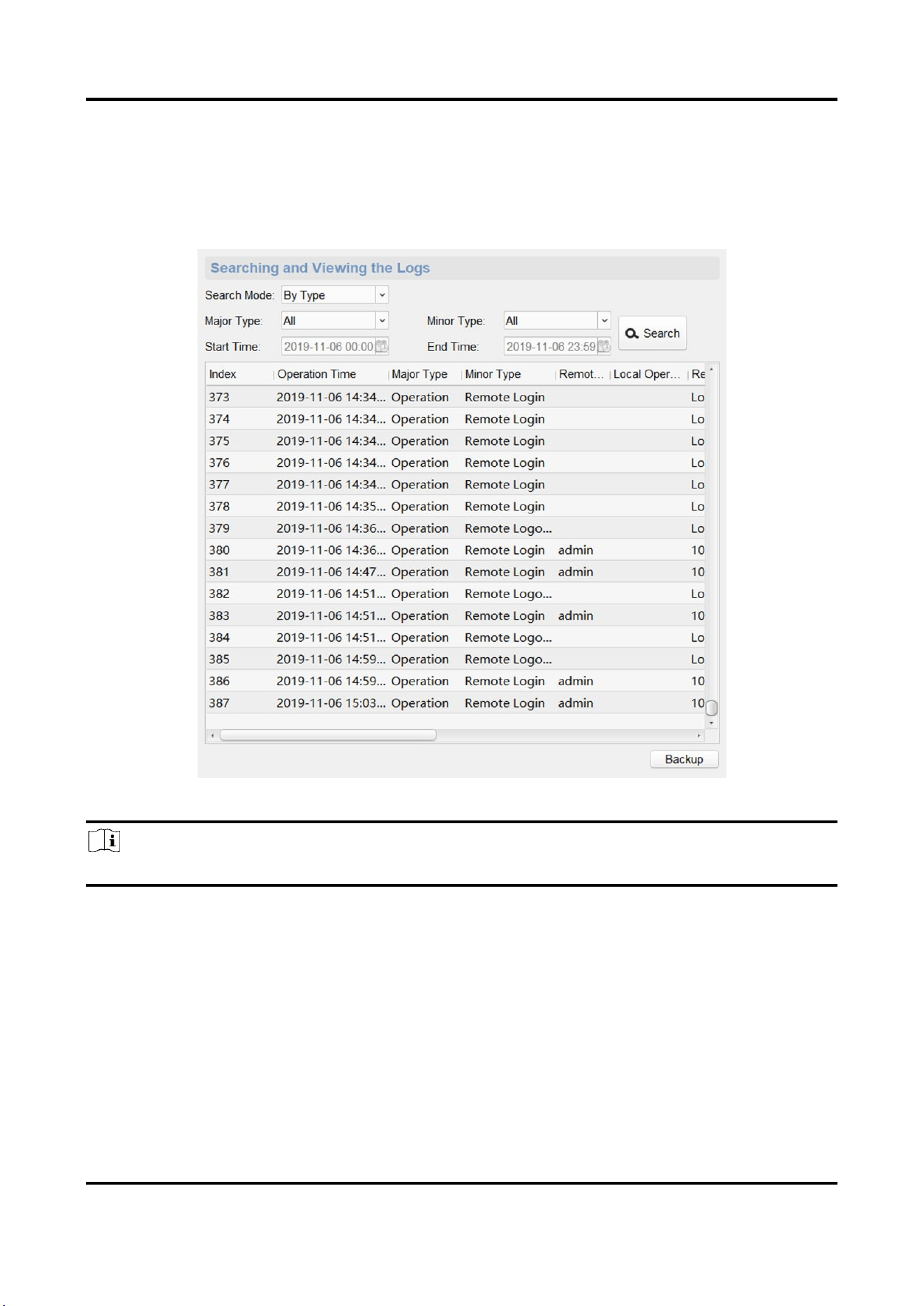
3.7.6 Search for Log
Search and view the alarm logs, exception logs, operation logs and event logs.
On the Remote Configuration page, go to System → Log.
You can set the search criteria and click Search, and the search result is in the list.
Figure 3-42 Search and View the Log
Note
You can click Backup and download the search result.
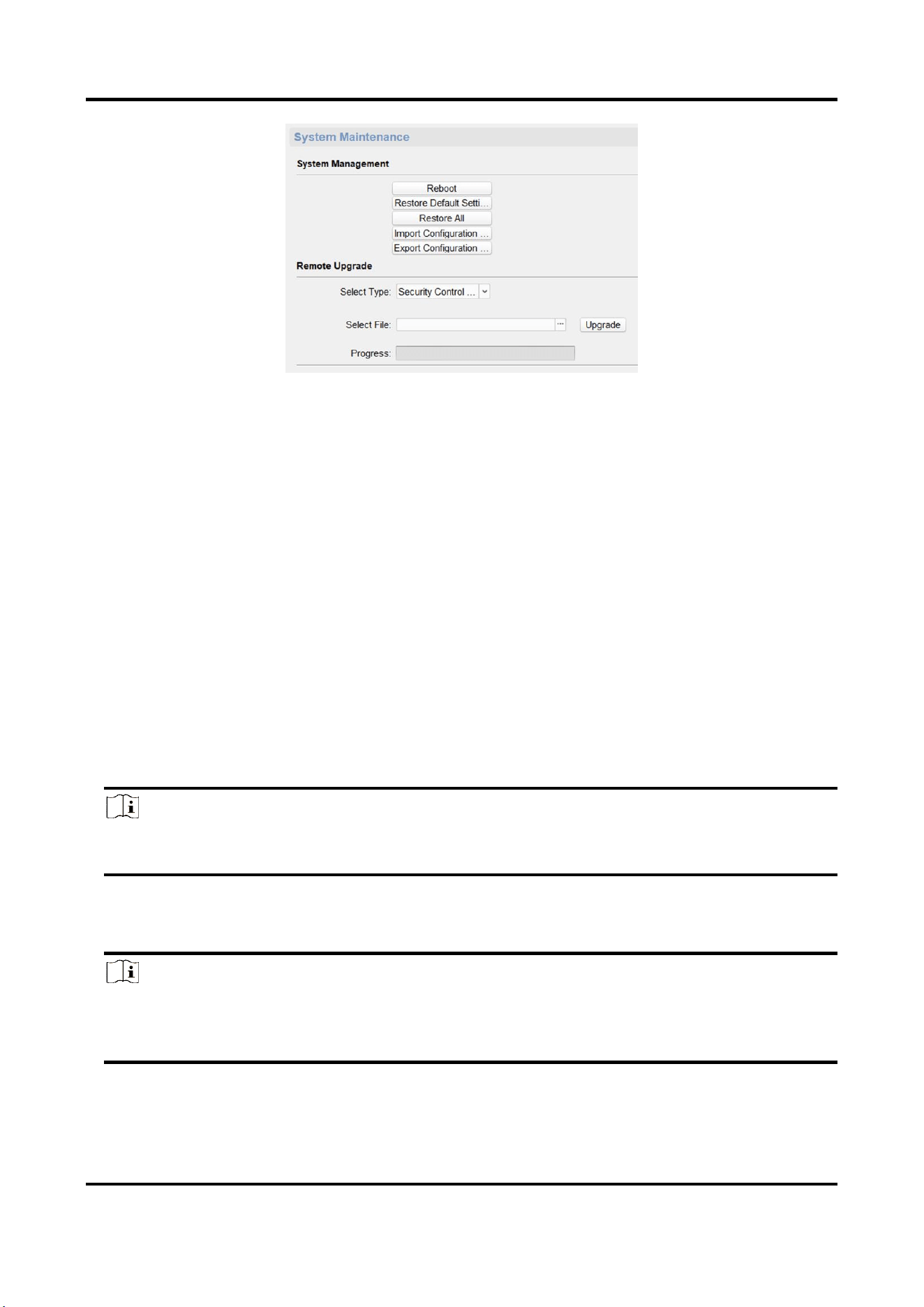
3.7.7 Maintain the System
System management and remote upgrade.
On the Remote Configuration page, go to System → System Maintenance.
Panic Alarm Station Configuration Guide
45
Figure 3-43 System Maintenance Page
System Management
You can reboot the device, restore default settings, restore all settings, and import/export
configuration file.
Reboot
Restart the device.
Restore Default Settings
Restore the default settings, that is, except the IP address and user information, all other
parameters of the device will be restored to factory default settings.
Restore All
Restore all the parameters to factory default settings, and the device needs to be reactivated
after restoring the parameters to default.
Import Configuration File
Import the configuration file from the client software to the device.
Note
The configuration file contains the parameter information of the device.
It is required to enter the password created when exporting when import a file.
Export Configuration File
Export the configuration file from the device to the client software.
Note
The configuration file contains the parameter information of the device.
It is required to set a password for the exported file. The password is used for importing
verification.
Panic Alarm Station Configuration Guide
46
Remote Upgrade
Upgrade the device remotely via the client software.
Click and select the upgrading file. And click Upgrade to upgrade the device.
Note
An invalid upgrade occurs when using a mismatched upgrade file, and then the device program is
still the program before the upgrade.
Caution
Do not power off the device during the upgrade process.
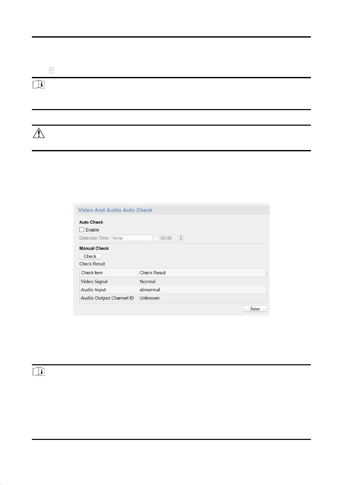
3.7.8 Check Video & Audio Status
Automatically or Manually check the video and audio status.
On the Remote Configuration page, go to System → Video and Audio Auto Check.
Figure 3-44 Video and Audio Check Page
Auto check
Check the video and audio status automatically.
Check Enable, set the detection time and click Save.
Note
The detection time can be selected as None, Everyday or one day of the week.
None
Auto check function is not enabled.
Panic Alarm Station Configuration Guide
47
Everyday
Check every day according to the set time.
One day of the week
The device performs a check at the set time on this day of the week.
Manual check
Click Check to start the check and the check results are displayed in the list.
Table 3-1 Description of Check Results
Check results
Description
Normal
Video/audio input/audio output signal is normal.
Abnormal
Video/audio input/audio output signal is loss.
Unknown
Audio input is abnormal and cannot detect audio output status.
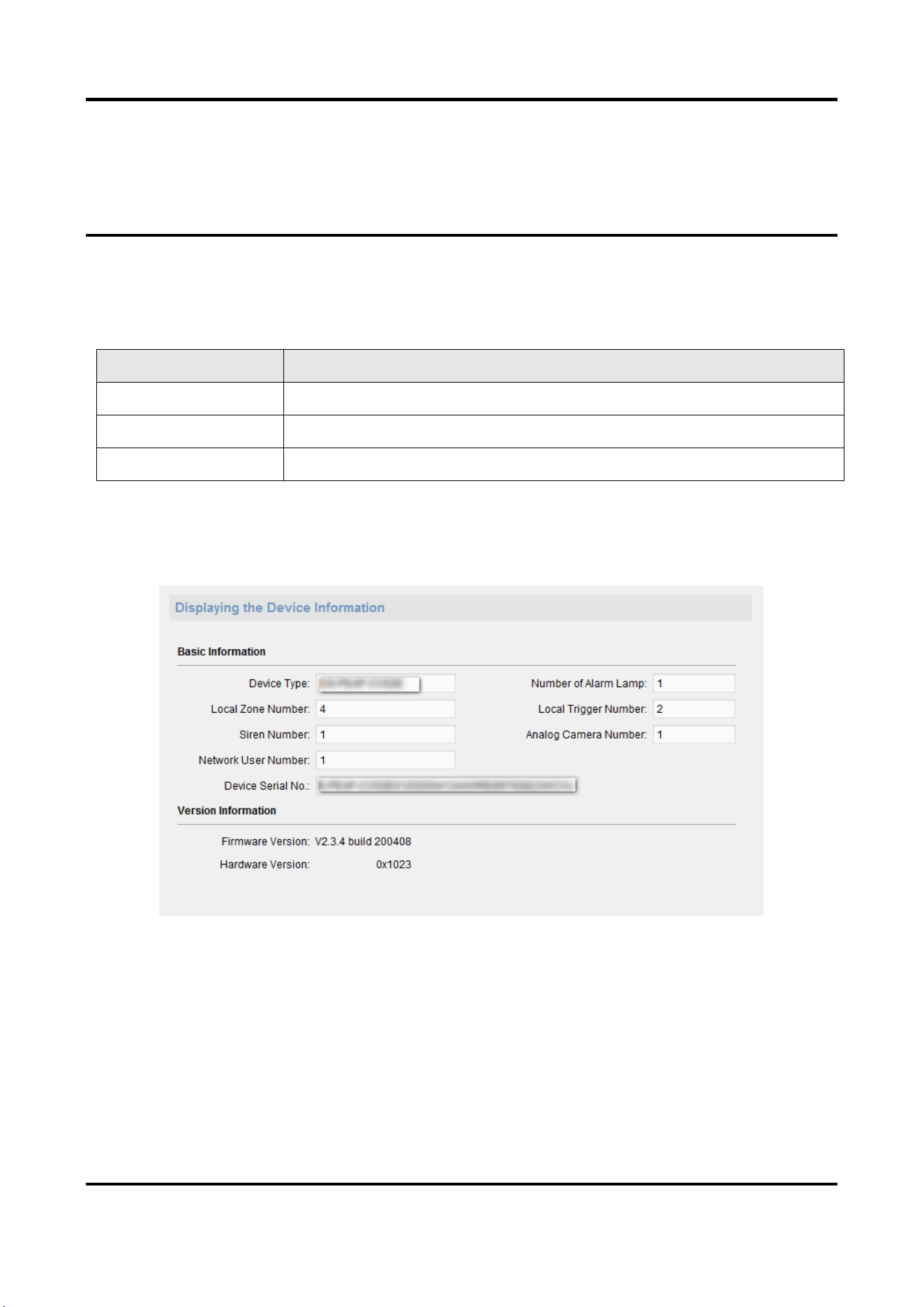
3.7.9 View Device Information
On the Remote Configuration page, go to Device Information→ Device Information.
Figure 3-45 View Device Information
3.8 Set Camera
Configure the camera parameters, including the camera, WDR (Wide Dynamic Range) function,
Panic Alarm Station Configuration Guide
48
and video standard.
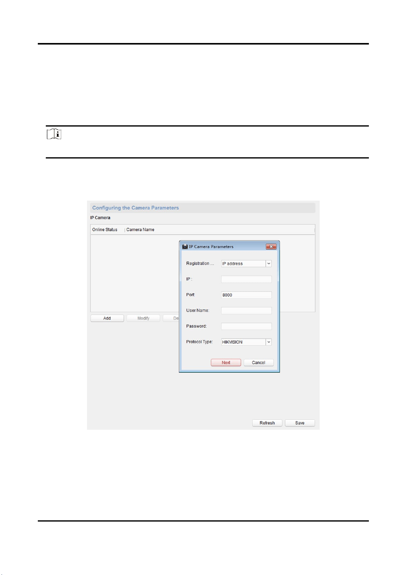
3.8.1 Add Camera
Add, modify and delete an external network camera, and enable the camera.
Steps
Note
Only one network camera can be added to the device.
1. On the Remote Configuration page, go to System → Camera.
2. Add a camera.
1) Click Add, and enter the IP address. port, user name, and password of the camera.
Figure 3-46 Add a camera
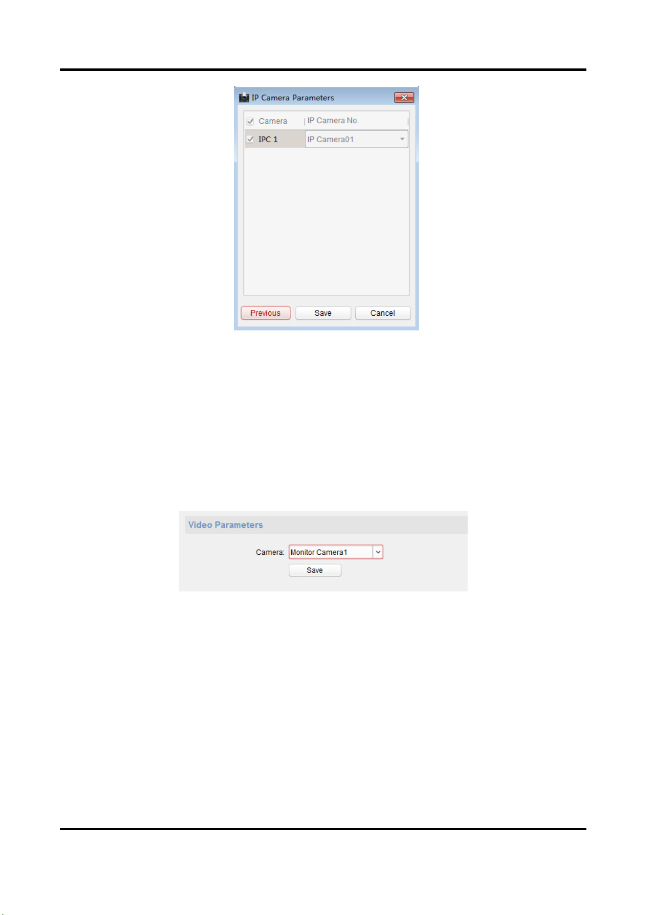
2) Click Next, select the camera number.
Panic Alarm Station Configuration Guide
49
Figure 3-47 Select the Camera Number
3) Click Save
3. Optional: You can select the camera in the list, and click modify to modify the camera
parameters, or click Delete to delete the added camera.
4. Click Save.
5. Optional: Click Refresh to refresh the camera status.
3.8.2 Set Video Parameters
On the Remote Configuration page, go to CCD → Video Parameters.
Figure 3-48 Video Configuration Page
Select the camera from the drop-down box. Click Save.
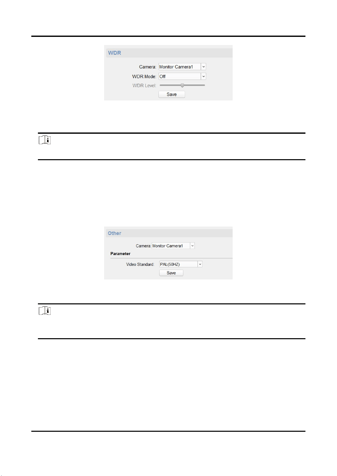
3.8.3 Set WDR
When WDR is enabled, the device automatically balances the brightest and darkest parts of the
camera picture, improving the dynamic range of the overall picture to see more details of the
camera picture.
Steps
1. On the Remote Configuration page, go to CCD → WDR.
Panic Alarm Station Configuration Guide
50
Figure 3-49 WDR function Configuration
2. Select a camera, set WDR Mode as On.
3. Set WDR Level.
Note
The WDR level can change the wide dynamic strength.
4. Click Save to enable WDR.
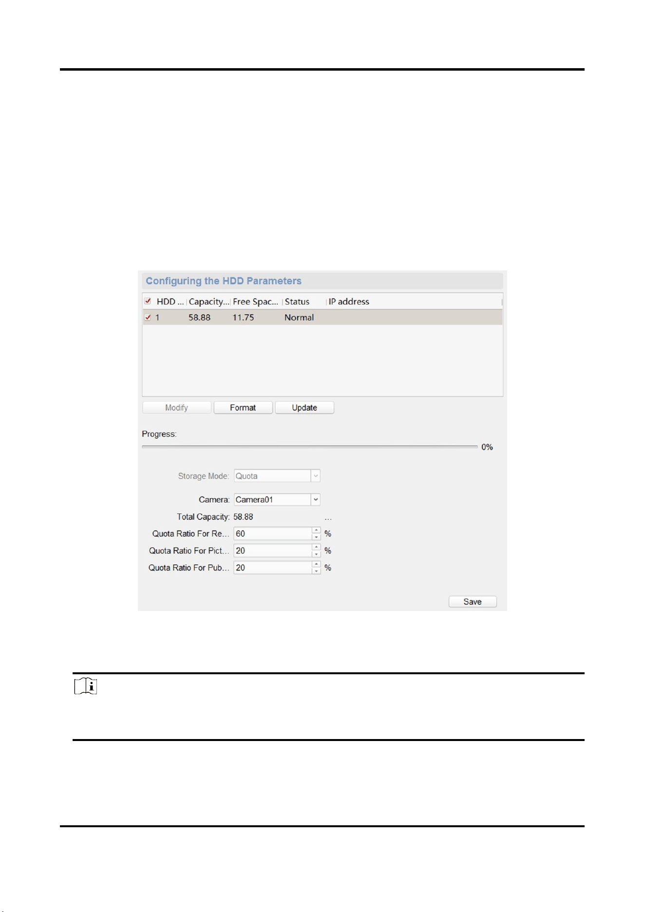
3.8.4 Set Other Parameters
Steps
1. On the Remote Configuration page, go to CCD → Other.
Figure 3-50 Video Standard Configuration Page
2. Select a camera, and set the video standard.
Note
When selecting Video Standard as PAL (50HZ), the highest frame rate is 25 fps, and when
selecting Video Standard as NTSC (60HZ), the highest frame rate is 30 fps.
3. Click Save to save settings.
Result
The changed video standard parameters take effect after restarting the device.
Panic Alarm Station Configuration Guide
51
3.9 Storage Settings
3.9.1 Initialize HHD
In order to store pictures and video files, you must format the MicroSD card first.
Steps
1. In the client software, go to Control Panel → Device Management, select the device in the
device list, and click Remote Configuration.
2. Click Storage → General.
Figure 3-51 HDD Parameters Configuration Page
3. Set the storage quota, and click Save.
4. Select and check the MicroSD card, click Format.
Note
The progress bar shows the formatted process. When the MicroSD card is formatted, the status
of the MicroSD card will display Active.

Panic Alarm Station Configuration Guide
52
3.9.2 Search for File
Search and download the record file and captured picture.
Steps
1. On the Remote Configuration page, go to Storage → File.
2. Select the searched file type as Record File or Captured Picture.
3. Select the camera, recording type, start time and end time, and click Search.
The search results are displayed in the list.
4. Click Download to download the result to PC.
3.10 Check Status
3.10.1 Check Zone Status
On the Remote Configuration page, go to Status → Zone, you can view the status of zone alarm.
3.10.2 Check Relay Status
On the Remote Configuration page, go to Status → Relay, you can view the relay status.
Panic Alarm Station Configuration Guide
53
Chapter 4 Communication Matrix and Device
Command
Scan the OR code for communication matrix
Scan the QR code for device command