Loading ...
Loading ...
Loading ...
EN
9
A QUALIFIED SERVICE MAN OR GAS APPLIANCE INSTALLER
MUST MAKE THE GAS SUPPLY CONNECTION.
Leak testing of the appliance shall be conducted by the
installer according to the instructions given.
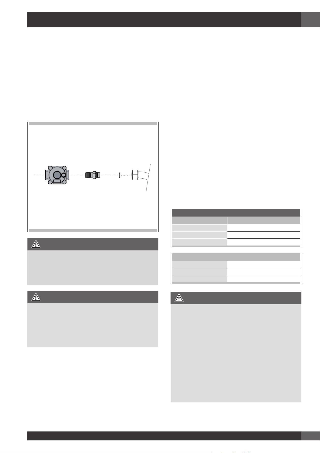
You must install the supplied connection parts seen here in
this configuration to the main gas manifold on the appliance.
Issues arising from a failure to do so will not be covered by
warranty.
Do not install the pressure regulator backwards as the gas will
not flow correctly. Check that the arrow on the back points in
the direction of gas flow.
Parts required for connection from gas supply to regulator are
the responsibility of the installer / owner
Appliance
pressure regulator
Flare union
adaptor
Gasket
Appliance
ATTENTION
Use Teflon tape rated for gas applications at all threaded
connections.
Do not overtighten the connection at the manifold or you
could damage the gasket causing a leak.
WARNING
If the line pressure supplying the appliance pressure
regulator exceeds 14 inches W.C. (any gas), an external
regulator must be installed in the gas line ahead of the
appliance regulator to reduce the pressure to no more
than 14 inches W.C. Failure to do this can result in
malfunction and damage to the appliance.
Important Notes for Gas Connection
The appliance and its individual gas shutoff valve must be
disconnected from the gas supply piping system during any
pressure testing of that system at test pressures in excess of
1/2 psi (3.5 kPa).
The appliance must be isolated from the gas supply piping
system by closing its individual manual shut-off valve during
any pressure testing of the gas supply piping system at test
pressures equal to or less than 1/2 psi (3.5 kPa).
All supply piping, except as noted, should use common
National Pipe Thread (N.P.T.). For all pipe connections use
an approved pipe joint compound resistant to the action of
LP gas.
This appliance is designed for use with NG gas or LP gas.
The gas pressure regulator is supplied with this appliance.
It must be installed in the gas way ahead of the manifold
entrance. It is pre-set for use with natural gas. To use it with
different gas it must be converted, as described in the Gas
conversion paragraph.
If at any time the appliance is to be used with a different
type of gas, all the conversion adjustments must be made
by a qualified technician before attempting to operate the
cooktop on that gas.
The gas should be supplied to the appliances pressure
regulator, at line pressure between 6 and 14 inches of
water column for NG, and between 11 and 14 inches of
water column for LP.
GAS REQUIREMENTS
NATURAL GAS WC
Manifold Pressure 5" (12.5 mb)
Min Line Pressure 6" (15 mb)
Max Line Pressure 14" (34.9 mb), .5 psi (3.5 kPa)
LP GAS WC
Manifold Pressure 10” (25 mb)
Min Line Pressure 11” (27.4 mb)
Max Line Pressure 14” (34.9 mb), .5 psi (3.5 kPa)
IMPORTANT
• NEVER REUSE OLD CONNECTORS WHEN INSTALLING
THIS COOKTOP.
To reduce the likelihood of gas leaks, apply teflon tape
or a thread compound approved for use with LP or
Natural gases to all threaded connections.
Apply a non-corrosive leak detection fluid to all joints
and fittings in the gas connection between the supply
line shut-off valve and the cooktop inlet.
Check for leaks!
Bubbles appearing around fittings and connections
will indicate a leak. If a leak appears, turn off supply
line gas shut-off valve, tighten connections, turn on
the supply line gas shutoff valve, and retest for leaks.
Never test for gas leaks with an open flame.
• NEVER TIGHTEN TO MORE THAN 35 ft lbs OF TORQUE.
4 - Gas Requirement
Loading ...
Loading ...
Loading ...