Thank you for purchasing a Sealey product. Manufactured to a high standard, this product will, if used according to these instructions,
and properly maintained, give you years of trouble free performance.
I
MPORTANT:
PLEASE READ THESE INSTRUCTIONS CAREFULLY. NOTE THE SAFE OPERATIONAL REQUIREMENTS, WARNINGS & CAUTIONS. USE
THE PRODUCT CORRECTLY AND WITH CARE FOR THE PURPOSE FOR WHICH IT IS INTENDED. FAILURE TO DO SO MAY CAUSE DAMAGE AND/OR
PERSONAL INJURY AND WILL INVALIDATE THE WARRANTY. KEEP THESE INSTRUCTIONS SAFE FOR FUTURE USE.
Refer to
instruction
manual
Wear eye
protection
Wear
protective
gloves
Wear protective
footwear
Wear ear
protection
Wear a mask
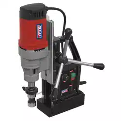
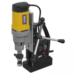
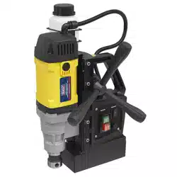
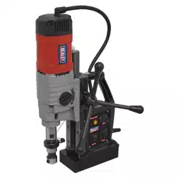
35MM LOW PROFILE MAGNETIC DRILLING
MACHINE 110V
MODEL NO: MAG35110VLP
1. SAFETY
1.1. ELECTRICAL SAFETY
WARNING! It is the user’s responsibility to check the following:
Check all electrical equipment and appliances to ensure that they are safe before using. Inspect power supply leads, plugs and all
electrical connections for wear and damage. Sealey recommend that an RCD (Residual Current Device) is used with all electrical
products. If the drilling machine is used in the course of business duties, it must be maintained in a safe condition and routinely PAT
(Portable Appliance Test) tested.
Electrical safety information, it is important that the following information is read and understood.
Ensure that the insulation on all cables and on the appliance is safe before connecting it to the power supply.
Regularly inspect power supply cables and plugs for wear or damage and check all connections to ensure that they are secure.
Ensure that the voltage rating on the appliance suits the power supply to be used.
DO NOT pull or carry the appliance by the power cable.
DO NOT pull the plug from the socket by the cable.
DO NOT use worn or damaged cables, plugs or connectors. Ensure that any faulty item is repaired or
replaced immediately by a quali ed electrician.
This product should be tted with a EN 60309 (110volt 16amp) plug.
If the cable or plug is damaged during use, switch the electricity supply and remove from use.
Replace a damaged plug with a EN 60309 (110volt 16amp) plug If in doubt contact a quali ed electrician.
A) Connect the GREEN/YELLOW earth wire to the earth terminal ‘E’.
B) Connect the BROWN live wire to the live terminal ‘L’.
C) Connect the BLUE neutral wire to the neutral terminal ‘N’.
Ensure that the cable outer sheath extends inside the cable restraint and that the restraint is tight.
Sealey recommend that repairs are carried out by a quali ed electrician.
1.2. GENERAL SAFETY
Enlist help to place the drill in its working position.
DO NOT allow non-essential persons, children or animals into the working area. Establish a cordon below.
DO NOT allow the use of this machine except by those who have received suitable training and have read these instructions.
If operating above ground level, use suitable staging to provide a safe working platform.
DO NOT work from ladders or steps.
Use non-original parts; use of such parts may be dangerous will a ect the warranty.
WARNING: Always wear approved eye or face protection when operating this drill. Use a face or dust mask if dust is generated.
DO NOT use near flammable gas or liquid, use only in a well lit and ventilated areas.
Remove ill fitting clothing, remove ties, watches, rings, and other loose jewellery, and contain long hair.
DO NOT operate whilst under the influence of drugs, alcohol or intoxicating medication, or if tired.
1.3. OPERATIONAL SAFETY
ALWAYS attach the drill to the work by means of the nylon security strap and buckle, in case of an electrical supply failure releasing
the electro-magnet.
Ensure that the machine is electrically isolated before installing in its working position and switched o before connecting to supply.
Ensure drill is switched o and isolated from mains supply before changing bit, or moving its position.
Check that the drill and its electric lead is not damaged before use. DO NOT use if any damage is evident.
Use non-original parts; use of such parts may be dangerous will a ect the warranty.
Ensure magnetic switch is in the o position before connecting to mains supply.
Only use water as coolant NOT antifreeze.
Keep drill dry.
If cut-out switch operates follow these steps: turn o power switch, wait for a few minutes, disconnect from mains.
DO NOT force the drill by pulling down on the handle with excessive force.
DO NOT use on non magnetic materials.
DO NOT use on the same steel work as electric welders are being used.
Brown
(L)
Yellow/
Green
(E)
Blue(N)
Cable
restraint
Original Language Version
© Jack Sealey Limited
MAG110VLP Issue 2 (ALL) 17/07/23
2. INTRODUCTION
Manufactured using high quality components for performance and reliability. Lightweight and compact made from heavy duty die cast
magnesium alloy. Fitted with a powerful magnet to ensure unit stays adhered at any angle. Includes safety xing strap, 10mm twist drill
chuck and integrated coolant system to extend the life of cutters and increase the quality of the cut. Designed for use in fabrication,
construction and other applications when drilling ferrous metal.
3. SPECIFICATION
Model No: .............................................. MAG35110VLP
Arbor: ................................................ 3/4” Weldon Shank
Magnet Adhesion: ...............................................14000N
Maximum Annular Cutter Capacity: ....................... 35mm
Maximum Cutter Depth: ........................................ 30mm
Motor Power: ........................................................1480W
No-Load Speed: .................................................. 640rpm
Stroke Length: ....................................................... 50mm
Supply .........................................................110V ~ 50Hz
Plug Type: ......................................... Yellow - 16A-2P+E
Power Supply Cable Length: ................................... 2.2m
Consumables (not included)
Neat Cutting Oil .................................................. NCO/5L
Soluble Cutting Oil ............................................. SCO/5L
Pilot Pin ............................................................. MAGC.P
4. ASSEMBLY
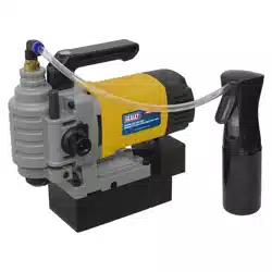
4.1. ATTACH COOLANT BOTTLE (g.1)
4.1.1. Connect coolant pipe to the connector on the drill head. (Pipe can be
released by pushing in the blue valve.)
4.1.2. Fill the bottle with appropriate lubricant (ref. Section 3).
4.2. FIT CUTTING BIT
4.2.1. Wind drill head up to maximum height.
4.2.2. Insert cutter and tighten the two cutter xings (g.1).
5. OPERATION
5.1. Mark the position of the hole to be drilled on the workpiece.
5.2. POSITION THE DRILL
5.2.1. Connect to the mains supply. Oer drill to workpiece and line up with the
previously marked hole.
WARNING! Make sure there is nothing between the magnet and the workpiece BEFORE turning the magnet on.
NOTE: When using drill vertically use the level indicator (g.1).
5.2.2. Ensure the drill head is wound back away from the workpiece before turning the magnet on.
5.3. ATTACH DRILL TO WORKPIECE
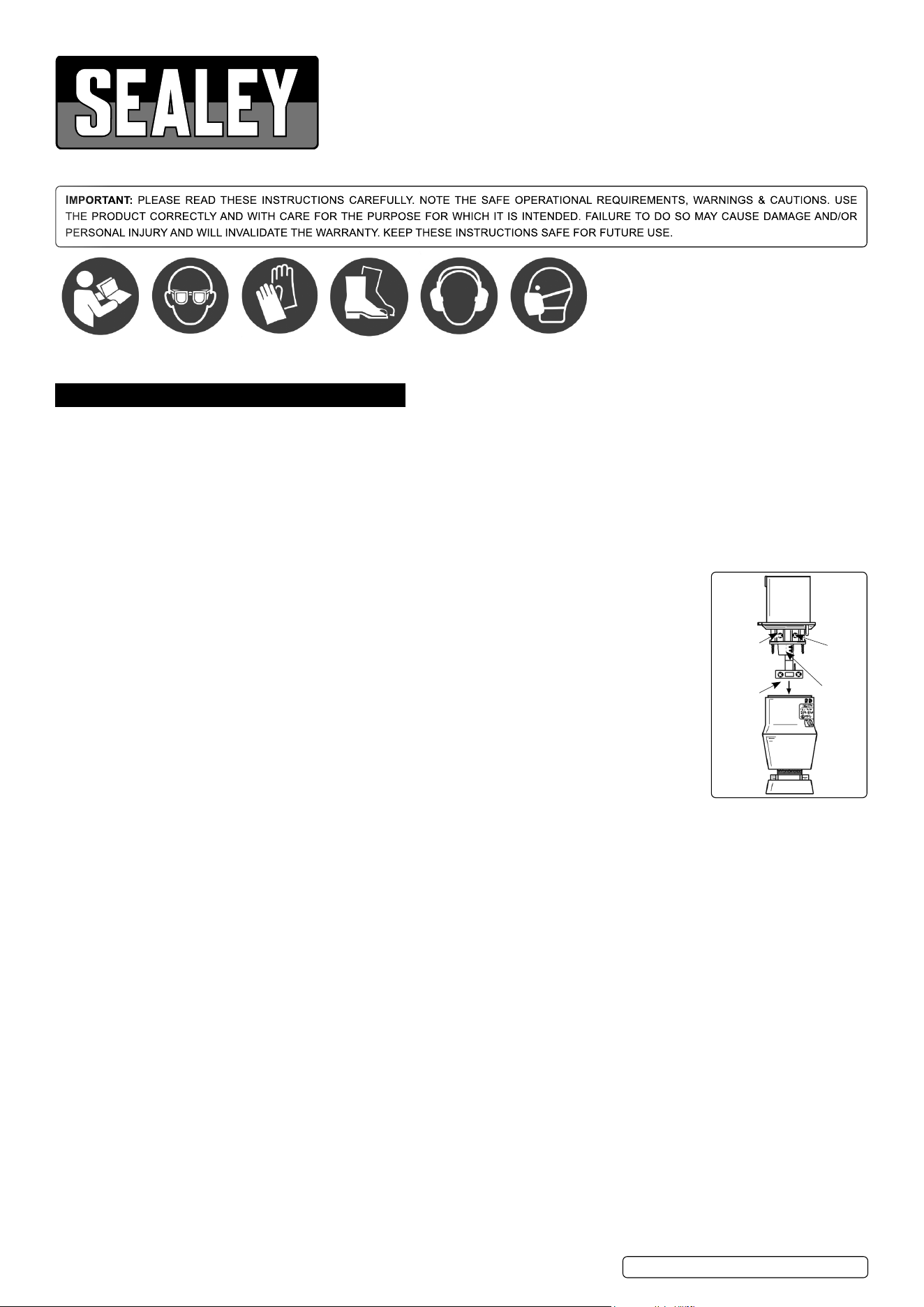
5.3.1. Turn the magnet on (g.2). Wind the drill head down to the workpiece and align the cutting head pin (not supplied).
5.4. FIT THE SAFETY STRAP
5.4.1. Place the safety strap though the handle of the drill and around the steelwork. Adjust the length of the strap so that if the drill should fall
the drill should not be allowed to swing too far and be damaged.
5.5. FILL COOLANT BOTTLE
5.5.1. Always use the correct cutting oil, refer to Section 3.
5.6. CUTTING THE HOLE
NOTE: Lubricate cutter by frequently squeezing trigger on coolant container (g.1).
5.6.1. Back the cutting head away from the workpiece, turn the drill motor on (g.2). Check the drill sounds and is operating normally.
5.6.2. Use ratchet drive (g.1) to move the cutting bit towards the workpiece.
5.6.3. Start feeding slowly, with not too much force, to prevent overloading the drill.
CAUTION! Prepare for bursting through the workpiece.
5.6.4. If the drill suddenly stops, you must turn o the motor switch immediately.
5.6.5. Once the hole has been cut, back the cutting head back out of the hole and switch o the motor.
5.6.6. Remove the debris from the cutting head.
5.6.7. Clean away swarf.
5.6.8. Undo the safety strap.
5.6.9. Support the weight of the drill and turn o the magnet. Remove the cutting bit and replace drill in its case.
fig.
1
fig.
2
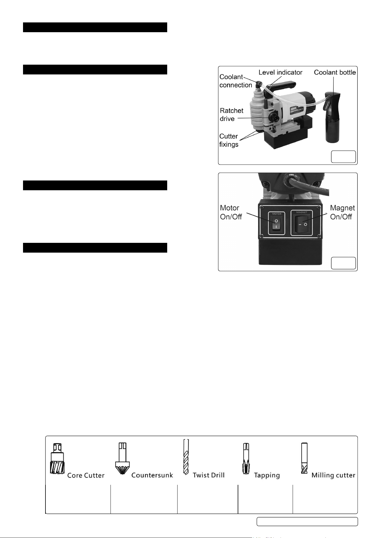
To remove a cylinder of
material, much like a hole
saw.
To create a cone-shaped
depression, to allow a
xing to sit ush with the
surface of the material.
To drill holes in a
variety of materials.
To cut threads inside
a hole.
To cut sideways to widen
a hole or taper it o.
Original Language Version
© Jack Sealey Limited
MAG110VLP Issue 2 (ALL) 17/07/23
6. MAINTENANCE
WARNING! Disconnect from mains supply before performing any maintenance.
6.1. Remove the cut ‘plug’ from the cutter, each time it is used.
6.2. Keep the tool clean.
6.3. Store in a dry, childproof location in its case.
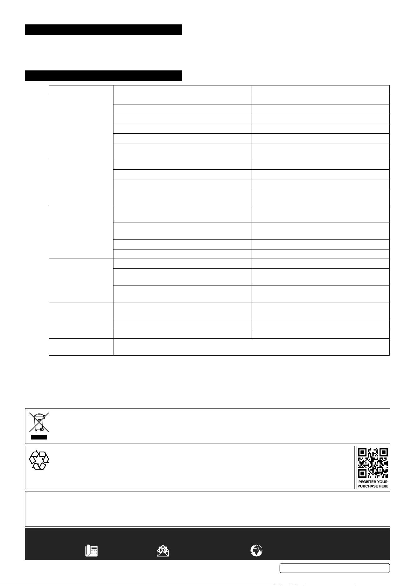
7. TROUBLESHOOTING
PROBLEM POSSIBLE CAUSE SOLUTION
Magnetic base does
not function
The contact of the switch is poor. Check/Repair the switch.
The power supply is broken. Check/Repair the power supply.
The circuit board is burned out. Replace the circuit board.
The electromagnet is short-circuited or burned out. Repair or replace the disk.
Not adsorbed on the steel frame. Change the adsorption surface.
The magnetic disk has been used for a long time
and has been heated and leaked.
Repair or replace the magnetic disk.
The machine does not
work after powering
up.
The contact of the switch is poor. Repair/Replace the switch.
Connectors are loose. Check the connectors.
Poor contact between brush and commutator. Repair or replace the brush.
The armature or stator coil of the electric drill is
burnt out.
Replace the armature or stator.
The magnetic base
suction is weak.
The suction workpiece is too thin. Replace the adsorption surface or thicken the
adsorption surface (>10mm steel sheet).
The adsorption surface is too small. Replace adsorption surface or temporarily weld thick
adsorption surface.
The support rod is not topped to the suction surface. The magnetic base suction is weak.
The diode may be pseudo-soldered. Reweld the diode.
The guide rail does not
run after turning the
handle.
The shaft key is broken. Replace the shaft key.
The gear and rack are misaligned. Loosen the screws under the rack and remove the
guide plate for repair.
The pin on the lifting gear is broken. Replace the pin.
Drill out the elliptical
hole.
The fasteners are loosened due to the vibration of
the machine.
The fasteners are loosened due to the vibration of
the machine.
Bit unilateral cutting. Regrind the bit.
There are impurities on the adsorption surface. Eliminate impurities.
Hard to shift gears. The machine must be turned o before changing gears. Turn the spindle with one hand and turn the shift
knob with the other.
Original Language Version
© Jack Sealey Limited
MAG110VLP Issue 2 (ALL) 17/07/23
Sealey Group, Kempson Way, Suffolk Business Park, Bury St Edmunds, Suffolk. IP32 7AR
01284 757500 sales@sealey.co.uk www.sealey.co.uk
ENVIRONMENT PROTECTION
Recycle unwanted materials instead of disposing of them as waste. All tools, accessories and packaging should be sorted,
taken to a recycling centre and disposed of in a manner which is compatible with the environment. When the product
becomes completely unserviceable and requires disposal, drain any fluids (if applicable) into approved containers and
dispose of the product and fluids according to local regulations.
Note: It is our policy to continually improve products and as such we reserve the right to alter data, specifications and component parts without prior
notice.
Important: No Liability is accepted for incorrect use of this product.
Warranty: Guarantee is 12 months from purchase date, proof of which is required for any claim.
WEEE REGULATIONS
Dispose of this product at the end of its working life in compliance with the EU Directive on Waste Electrical and Electronic Equipment
(WEEE). When the product is no longer required, it must be disposed of in an environmentally protective way. Contact your local solid
waste authority for recycling information.