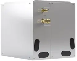

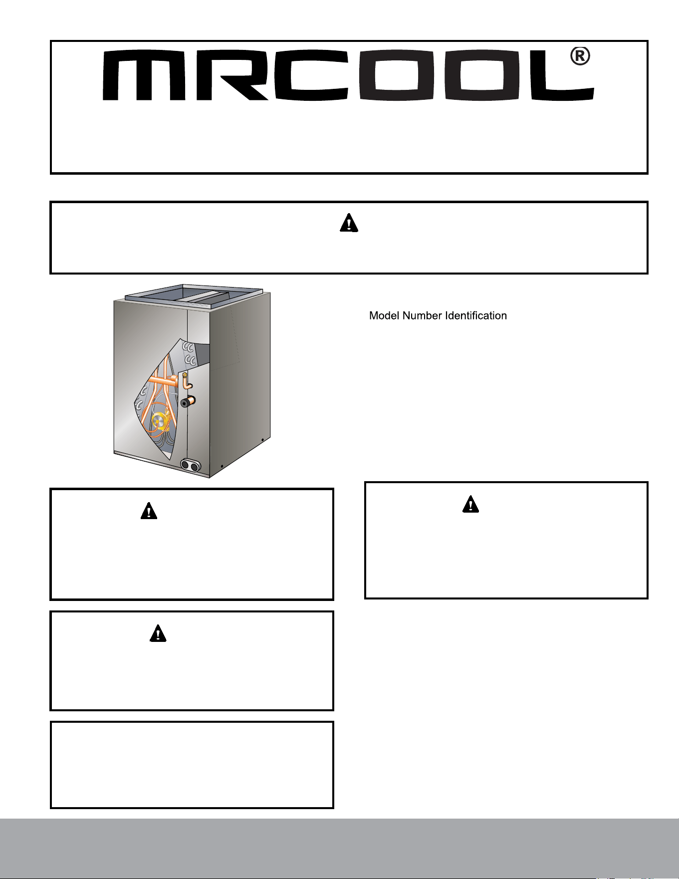
Signature Series
MCVP* & MCHP* Series Coils
Please read this manual carefully before installation and keep it for future reference.
Due to updates and constantly improving performance, the information and instructions within this
manual are subject to change without notice. Please visit www.mrcool.com/documentation to
ensure you have the latest version of this manual.
Version Date: 05-24-21
Installation Manual
This manual must be left with the homeowner for future reference.
This is a safety alert symbol and should never be ignored. When you see this symbol on labels or in manuals, be alert to
the potential for personal injury or death.
Improper installation, adjustment, alteration, service or
maintenance can cause personal injury, loss of life, or
damage to property.
Installation and service must be performed by a licensed
professional installer (or equivalent) or a service agency.
WARNING
As with any mechanical equipment, contact with sharp
sheet metal edges can result in personal injury. Take
care while handling this equipment and make sure to
wear gloves and protective clothing.
CAUTION
The Clean Air Act of 1990 bans the intentional venting
of refrigerant (CFCs, HCFCs and HFCs) as of July
1, 1992. Approved methods of recovery, recycling or
reclaiming must be followed. Fines and/or incarceration
may be levied for noncompliance.
IMPORTANT
Table of Contents
........................................2
General ........................................................................3
Shipping and Packing List ...........................................3
Releasing Air Charge ..................................................3
Installation ...................................................................3
Refrigerant Line Connections .....................................4
Leak Testing, Evacuating and Charging .....................5
Sealing Ducts .............................................................6
Condensate Drain Connections ..................................6
Blower Speed Selection .............................................7
Maintenance ...............................................................8
INSTALLATION INSTRUCTIONS
Signature Series Indoor Coils
Manufactured By:
MRCOOL
®
,
LLC
48 Remington Way
Hickory, KY 42051
Page 1
mrcool.com
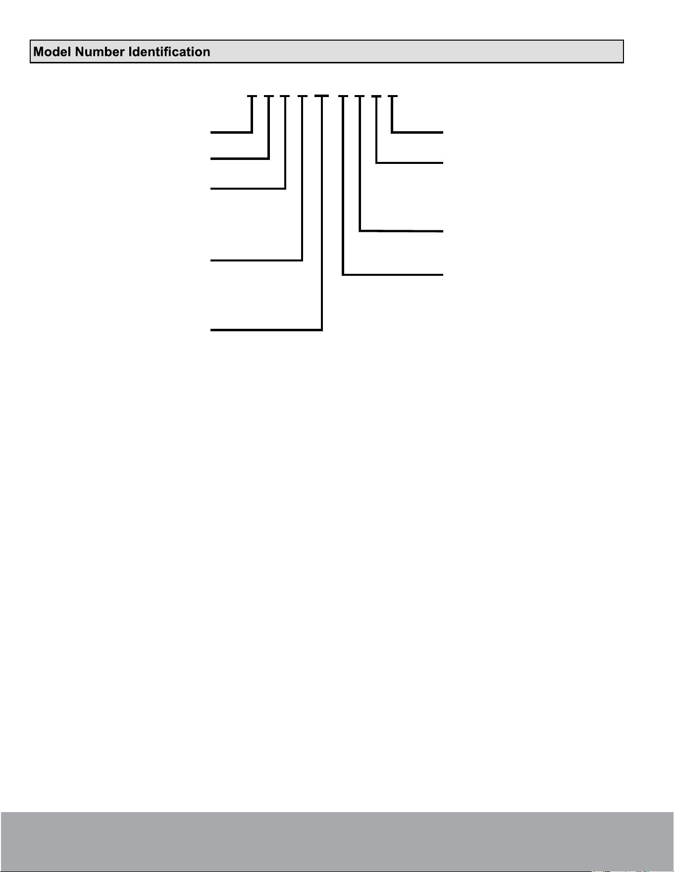
M C V P 24 A N P A
MRCOOL
Coil
Air Flow
M = Upflow/Horizontal
V = Upflow
H = Horizontal
Case
C = Unpainted
U = Uncased
P = Painted
Capacity
(MBTU/H)
2nd Gen
Refrigerant
N = R410
R = R-22
Coil Dimension
A = 14.5
B = 17.5
C = 21
D = 24.5
Metering Device
O = Orifice
T = TXV
C = Capillary
P = Piston
Page 2
mrcool.com
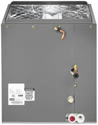
NOTE: Special procedures are required for cleaning the
aluminum coil in this unit. See Page 8 in this instruction
for information.
General
The MCV* & MCH* coils are only available cased and
metering device that must be replaced if the system match
of 500°F. The drain pan must be at least 2" away from a
may damage the drain pan and cause a leak.
and line sets.
These instructions are intended as a general guide and
do not supersede local or national codes in any way.
Authorities who have jurisdiction should be consulted
before installation.
Shipping and Packing List
Package 1 of 1 contains:
1 – Evaporator coil
Check the components for shipping damage; if found,
immediately contact the last carrier.
Releasing Air Charge
The coil is shipped from the factory pressurized with dry
air. Pierce a hole in the rubber plug that seals the vapor
line to relieve the pressure before removing the plugs.
CAUTION
NOTE: If there is no pressure released when the vapor
line rubber plug is pierced, check the coil for leaks before
continuing with the installation.
The MCVP* and MCHP* coils are shipped with a 10 psi dry
air holding charge. Puncture the suction line rubber plug to
release the charge. Remove the rubber plug. Ensure that
the coil is void of pressure.
Installation
Can cause injury or death.
Recover all refrigerant to relieve pressure before
opening the system.
WARNING
Install the furnace or air handler and condensing unit
according to the installation instructions provided with the
unit.
Position the cased coil on top of the furnace or air handler
NOTE: If the coil is to be installed on an oil furnace, it may
possible damage to the coil drain pan. See the oil furnace
installation instructions for details.
NOTE: The coil cabinet has six screw clearance holes
which should be aligned with the furnace engagement
holes. Secure the coil cabinet to the furnace or air handler
" screws.
Air Leakage
All indoor cabinets MUST be taped after installation to seal
include a factory-installed HFC-410A fixed orifice (RFC)
valve.
Page 3
mrcool.com
Refrigerant Line Connections
Line Sizes
The refrigerant line sets should be sized according to the
recommendations given in the condensing unit installation
instructions. Use Table 1 to determine correct braze
to match line set connections.
Model Number Suction Liquid
18/24
24
30
30/36
36
3/4 Inch
3/8 Inch
48
49
50/60
60
7/8 Inch
Table 1. Refrigerant Line Connections
Replacement Parts
If replacement parts are necessary, order kit 69J46. The
kit includes:
• 10 – Brass nuts for liquid line assemblies
•
•
• 10 Liquid line assemblies
TEFLON RINGS (20)
BRASS NUTS (10)
LIQUID LINE ASSEMBLIES
(INCLUDES STRAINER) (10)
LIQUID LINE ORIFICE HOUSINGS (10)
LIQUID LINE
ASSEMBLY
COPPER
TUBE
PISTON
RETAINER
STRAINER
Figure 1. 69J46 Kit Components
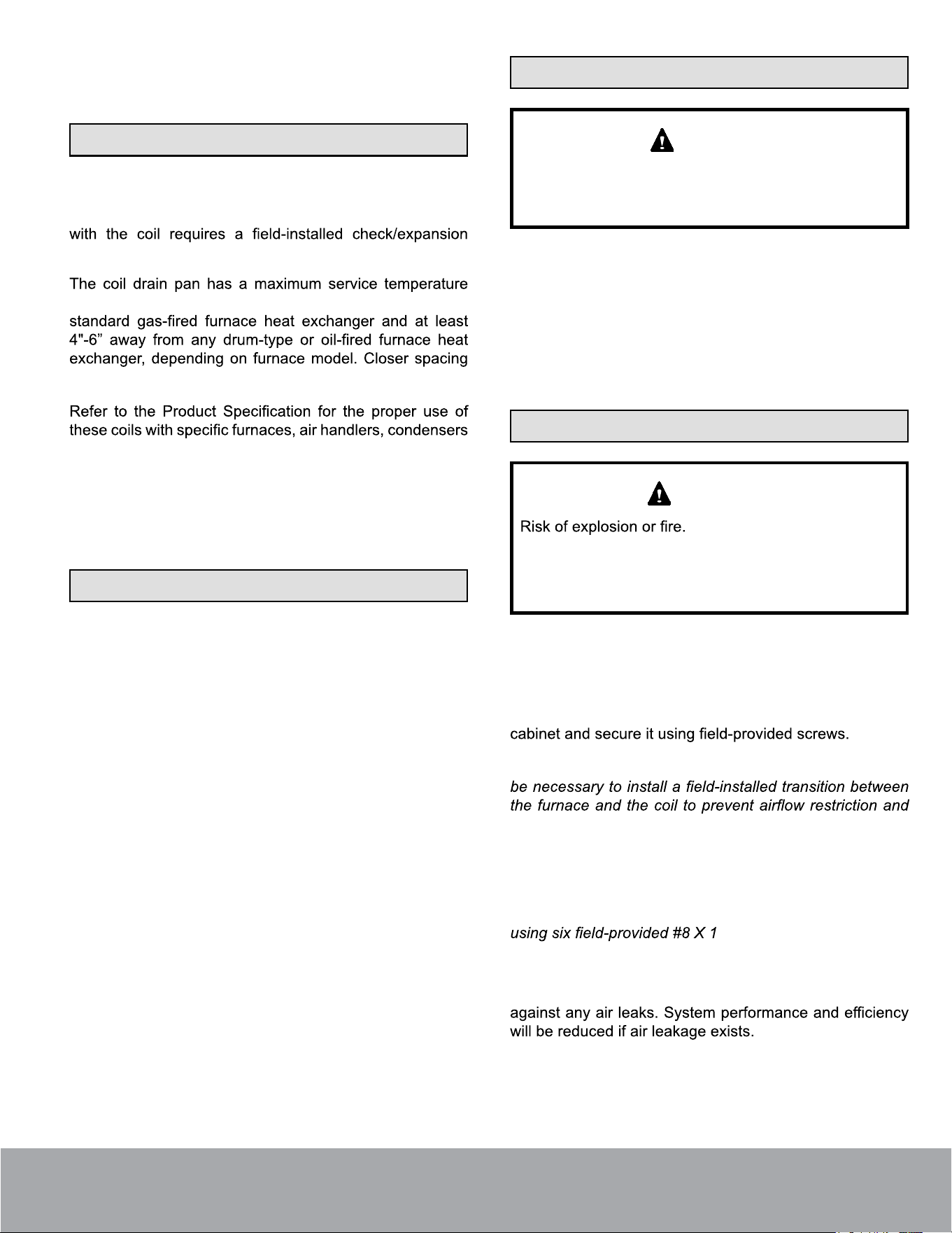
Brazing Guidelines
Use a silver alloy brazing rod (5 or 6 percent silver alloy for
copper-to-copper connections or 45 percent silver alloy for
copper-to-brass or copper-to-steel connections).
heat shield, such as a wet rag, against the unit cabinet
bulb. The heat shield must be in place to prevent heat
damage during brazing. See Figure 2.
WATER-
SATURATED
RAGS
PLACE A WET RAG AGAINST
COIL CABINET AND AROUND
THE SUCTION LINE
CONNECTION.
BRAZE CONNECTION. ALLOW
PIPE TO COOL BEFORE
REMOVING WET RAG.
1
2
Figure 2. Braze Refrigerant Lines
Suction Line Connection
Use the following procedure to connect the suction line to
the indoor coil:
1. Remove rubber plug from the stubbed connection.
2. Position the properly sized refrigerant piping and
make the brazed connection following the brazing
guidelines.
3. Do not remove the water-saturated rags from the
cabinet and piping until the piping has cooled
completely.
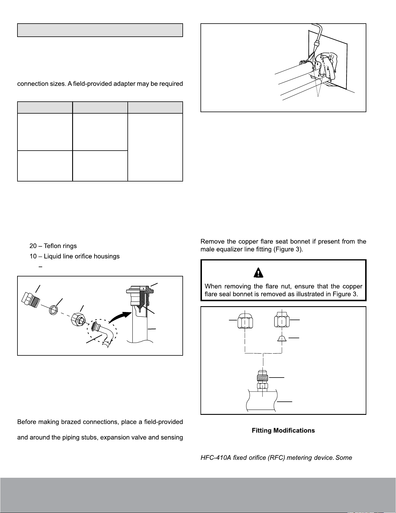
Suction Line Equalizer Fitting
IMPORTANT
SUCTION LINE
FLARE NUT
REMOVE AND DISCARD FLARE
SEAL BONNET IF PRESENT
MALE BRASS EQUALIZER LINE
FITTING
FLARE
SEAL CAP
OR
Figure 3. Suction Line Male Equalizer Line
Liquid Line Connection
NOTE:
system matches with this coil require use of a check/
expansion valve.
The coils are shipped with a factory-installed
Page 4
mrcool.com

NOTE: If the system match requires an HFC-410A check/
expansion valve is installed.
1. Remove the coil access and plumbing panels.
2. Remove any shipping clamps that secure the liquid
line and distributor assembly.
3. Using two wrenches, disconnect the liquid line stub
damage the distributor tubes during this process.
4.
Figure 4.
5. Retain brass nut to be used later with the liquid line
assembly.
O-RING
REMOVE AND DISCARD
WHITE TEFLON SEAL
STRAINER
DISTRIBUTOR
TUBES
LIQUID LINE
STUB
ORIFICE HOUSING
(REMOVE ORIFICE
FROM INSIDE OF
HOUSING)
Figure 4.
Some system matches for the MCVP* and MCHP* coil
installation of the valve and sensing bulb.
See the MCVP* and MCHP* product specifications for
approved expansion valve match-ups and application
information.
1.
bulb have been installed per the kit instructions,
braze the properly sized refrigerant piping into place.
Carefully follow brazing guidelines and use wet rags to
prevent heat damage.
2. Do not remove the water-saturated rags from the
cabinet and piping until the piping has cooled
completely.
NOTE: To prevent any possibility of water damage,
properly insulate all parts of the expansion valve assembly
the valve and its surrounding ambient temperatures.
Leak Testing, Evacuating and Charging
Refer to the outdoor unit instruction for leak testing,
evacuating and charging procedures. Always leak check
entire system before charging.
Page 5
mrcool.com
require a check/expansion valve. The expansion valve must
be installed external to the indoor coil cabinet. Refer to the
instructions provided with the expansion valve kit for proper
Sealing Ducts
There must be an airtight seal between the bottom of
sealing strips, caulking, or equivalent sealing method
between the plenum and the air handler cabinet to
ensure a tight seal. Return air must not be drawn from a
room where the air handler or any gas-fueled appliance
WARNING
Ensure that the duct is secured and all joints are properly
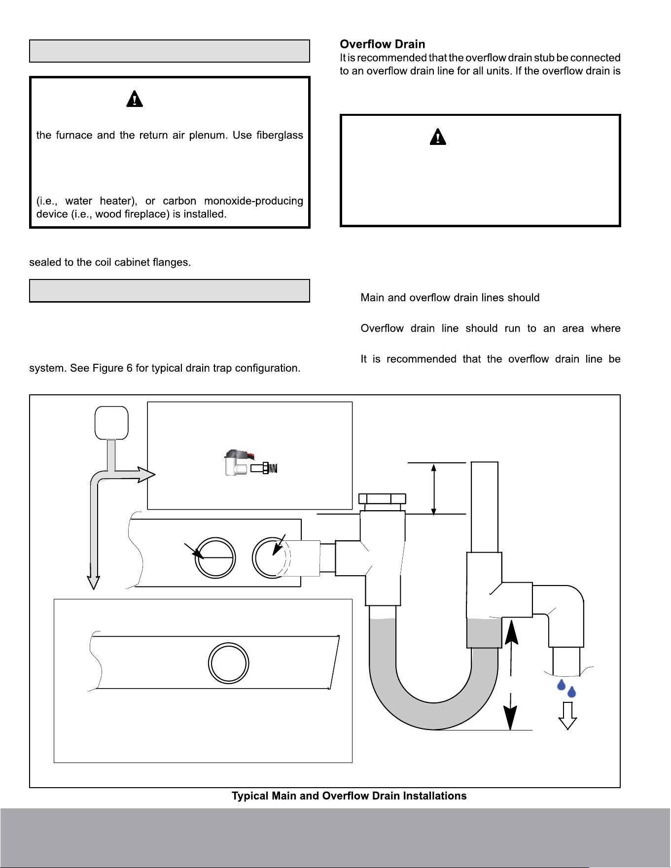
Condensate Drain Connections
Main Drain
Connect the main drain and route drain tubing downward to
drain line or sump. Do not connect drain to a closed waste
not connected to a drain line, it must be plugged with the
provided cap.
After removal of drain pan plug(s), check drain hole(s)
to verify that drain opening is fully open and free of any
debris. Also check to make sure that no debris has
fallen into the drain pan during installation that may plug
up the drain opening.
IMPORTANT
Condensate Drain Recommendations
The following practices are recommended to ensure better
condensate removal:
• NOT be smaller
than both drain connections at drain pan.
•
homeowner will notice drainage.
•
vented and a trap installed. Refer to local codes.
ABOVE
FINISHED
SPACE?
OVERFLOW DRAIN LINE
ALWAYS RUN AN OVERFLOW DRAIN LINE. IF NOT POSSIBLE TO
ROUTE OVERFLOW DRAIN LINE, INSTALL LOW VOLTAGE
OVERFLOW SWITCH KIT. WIRE KIT TO SHUT DOWN
COMPRESSOR PER INSTRUCTIONS.
NO
YES
CLEAN OUT
VENT
PRESS IN
(DO NOT GLUE)
VENT MUST EXTEND
ABOVE HEIGHT OF
COIL DRAIN PAN BY
TWO INCHES
1” X 3/4” X 3/4”
REDUCING
TEE WITH
PLUG
PVC
SCH 40 P- OR
J-TRAP 3/4”
OVERFLOW
DRAIN
OPTIONAL
SAFETY
PAN
COIL DRAIN PAN
WHEN A COIL IS LOCATED ABOVE A FINISHED SPACE, A 3/4” SECONDARY DRAIN LINE
MUST BE:
● CONNECTED TO SECONDARY DRAIN PAN
OR
● CONNECTED TO THE OVERFLOW DRAIN OUTLET OF THE AIR HANDLER DRAIN PAN.
TRAPS MUST BE DEEP ENOUGH TO OFFSET MAXIMUM STATIC DIFFERENCES —
GENERALLY, TWO INCHES.
DRAIN LINE SHOULD
SLOPE A MINIMUM OF
ONE INCH PER 10 FT.
NOTE — WHEN A AIR HANDLER IS LOCATED ABOVE A FINISHED SPACE THE SECONDARY
DRAIN PAN MUST HAVE A LARGER FOOTPRINT THAN THE AIR HANDLER.
MAIN
DRAIN
TO APPROVED
DRAIN
FOR NEGATIVE PRESSURE COILS (BLOWER
AFTER COIL) TRAPS ARE REQUIRED ON ALL
DRAIN LINES CONNECTED TO COIL.
COMPACT OVERFLOW SWITCH WITH 3/4” FEMALE SLIP INLET
AND MALE ADAPTER, TWO PART DESIGN FOR USE WHERE
OBSTRUCTIONS PREVENT DIRECT THREADING
SECONDARY
DRAIN PAN
2”
(51 MM)
TRAP DEPTH
Figure 6.
Page 6
mrcool.com
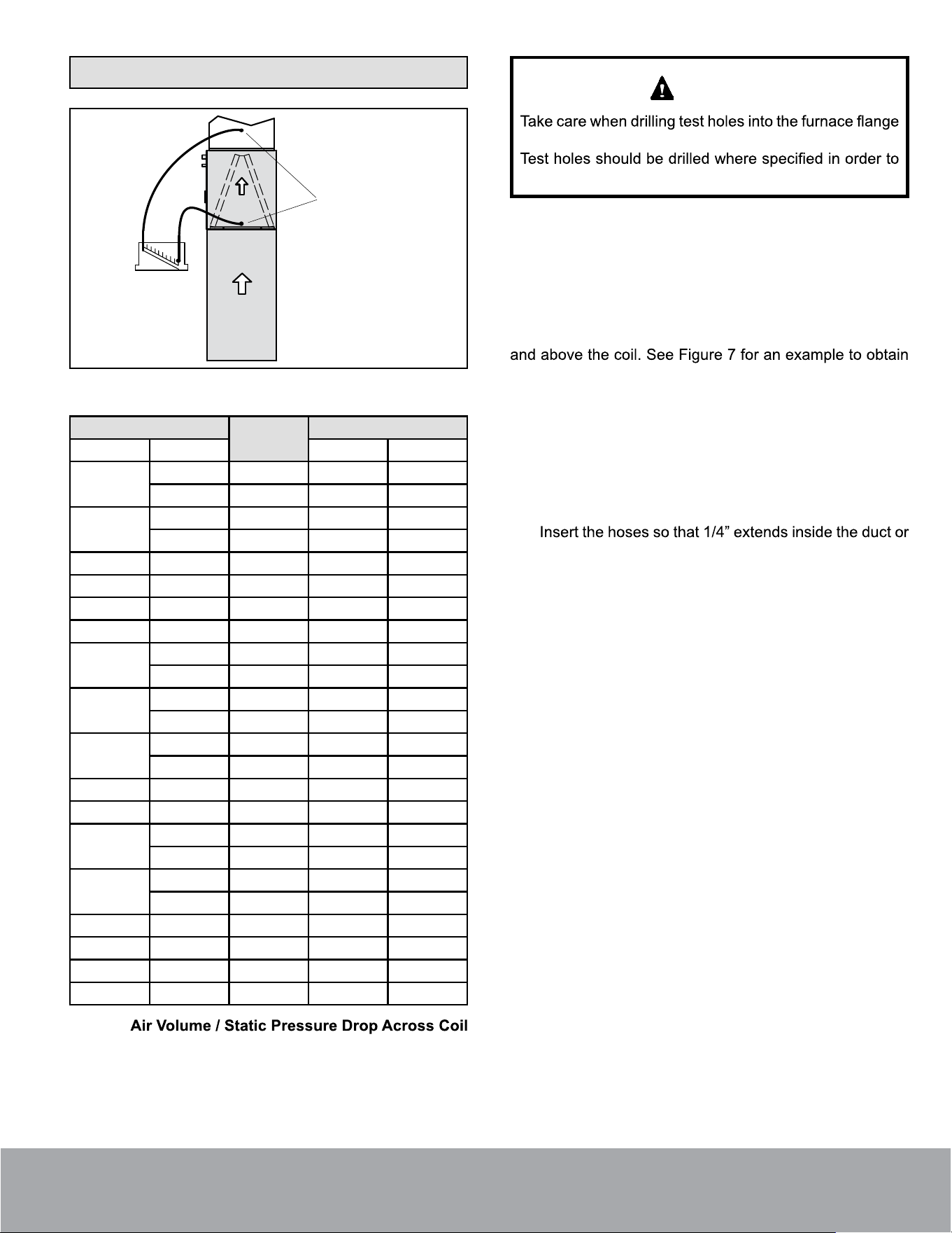
Blower Speed Selection
LEFT-HAND AIR
DISCHARGE (TOP VIEW)
TEST HOLES
AIR FLOW
Figure 7. Static Pressure Test
Cabinet
Vol: CFM
Drop: in. w.g.
Model Width in. Dry Wet
18/24ANPA
14.5 600 .11 .17
14.5 800 .18 .25
18/24BNPA
17.5 600 .11 .17
17.5 800 .18 .25
24ANPA 14.5 800 .16 .18
24BNPA 17.5 800 .16 .18
30ANPA 14.5 1000 .18 .20
30BNPA 17.5 1000 .18 .20
30/36ANPA
14.5 1000 .19 .21
14.5 1200 .27 .30
30/36BNPA
17.5 1000 .13 .16
17.5 1200 .17 .21
30/36CNPA
21 1000 .13 .16
21 1200 .17 .21
36ANPA 14.5 1200 .27 .30
36BNPA 17.5 1200 .17 .21
48BNPA
17.5 1400 .23 .24
17.5 1600 .30 .31
48CNPA
21 1400 .13 .16
21 1600 .16 .20
49CNPA 21 1600 .17 .22
50/60CNPA 21 1600 .23 .29
60CNPA 21 2000 .29 .34
60DNPA 24.5 2000 .21 .27
Table 2.
and the duct. Drill holes away from refrigerant piping.
avoid unit damage.
CAUTION
Proper air volume must be provided over the evaporator
coil. Select a blower motor speed tap that will provide 400
± 50 CFM per 12,000 Btu/h of cooling capacity (wet coil). A
static pressure reading must be taken to see if the pressure
drop falls within the proper range. See Table 2.
To ensure accuracy, air must be read from below the coil
an accurate reading.
1. Drill one 5/16” air test hole into the delta plate between
the coil slabs.
2. Drill one 5/16” air test hole into the duct above the top
of the coil.
3. Connect the instrument for static pressure
measurement hoses to the air entering side of coil.
end seal. Seal around holes with sealant.
4.
Turn on electrical power to the furnace and set the
thermostat to initiate a cooling demand.
5.
Table 2 lists air volumes and equivalent static pressure
readings for these units. Observe the static pressure
reading. If the reading is below the required air
volume, increase the blower speed; if the reading is
above the required air volume, decrease the blower
speed. Refer to the furnace wiring diagram for blower
speed settings.
6.
When the required static pressure readings are
obtained, remove the test hose lines and insert snap
hole plugs into test holes.
Page 7
mrcool.com
Maintenance
Failure to follow instructions will cause damage to the
unit.
This unit is equipped with an aluminum coil. Aluminum
pH below 5 or above 9. The aluminum coil should be
cleaned using potable water at a moderate pressure
(less than 50 psi). If the coil cannot be cleaned using
water alone, AAE recommends use of a coil cleaner
with a pH in the range of 5 to 9. The coil must be rinsed
thoroughly after cleaning.
In coastal areas, the coil should be cleaned with potable
water several times per year to avoid corrosive buildup
(salt).
NOTE
A trained technician or service agency must perform
maintenance and service on equipment. At the beginning
of each heating or cooling season, indoor coils should be
cleaned.
on coils. These chemicals are not necessary to dissolve
used to dissolve oils and greases, which generally are not
present on most installations.
Cleaning The Coil
1. Remove the coil from the cabinet or plenum, and take
the coil to an appropriate place to clean it.
2. Vacuum or brush the coil to remove matted and
3. If oil deposits are present, spray the coil with a mild
household liquid detergent to soften deposits. Do
not leave the detergent on the coil for more than 10
minutes. Flush the coil thoroughly with potable water.
NOTE: For units in coastal regions, fresh water will
4. Spray the coil at a vertical angle of 30 to 45 degrees
with a constant stream of water at moderate pressure.
A pressure washer with a fan nozzle will work best. Do
not spray the coil from a horizontal direction.
5. Direct the spray so that any debris is washed out of the
coil and base pan. For most residential units, hot water
is not necessary.
NOTE:
coil will require removing parts from the unit, and it
Attempting to blow water through a coil will slow the
6. Replace the coil into the cabinet or plenum. Ensure
that you have followed the proper procedure for routing
and securing the refrigerant tubing.
Ensure that the distributor lines are not rubbing together
or kinked. All tubes must have enough clearance from
other metal parts. Use wire ties to secure tubes to
prevent movement that could cause the refrigerant
tubing to fail.
IMPORTANT
Page 8
mrcool.com

Signature Series
Please read this manual carefully before installation and keep it for future reference.
Consult with the sales agency or manufacturer for details.