TROY-BILT LLC, P.O. BOX 361131 CLEVELAND, OHIO 44136-0019
Printed In USA
Op e r a t O r ’s Ma n u a l
Safe Operation Practices • Set-Up • Operation • Maintenance • Service • Troubleshooting • Warranty
WARNING
READ AND FOLLOW ALL SAFETY RULES AND INSTRUCTIONS IN THIS MANUAL
BEFORE ATTEMPTING TO OPERATE THIS MACHINE.
FAILURE TO COMPLY WITH THESE INSTRUCTIONS MAY RESULT IN PERSONAL INJURY.
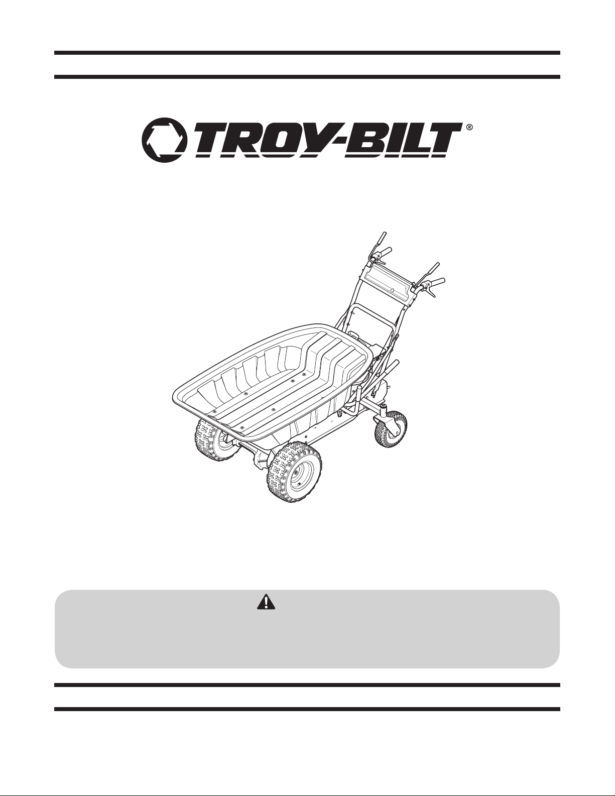
Gas Powered Wheelbarrow — Pack Horse
Form No. 769-05016
(June 10, 2009)

Customer Support
Please do NOT return the machine to the retailer or dealer without first contacting our Customer Support Department.
If you have difficulty assembling this product or have any questions regarding the controls, operation, or maintenance of
this machine, you can seek help from the experts. Choose from the options below:
Visit us on the web at www.troybilt.com◊
Call a Customer Support Representative at (800) 828-5500 or (330) 558-7220◊
Write us at Troy-Bilt LLC • P.O. Box 361131 • Cleveland, OH • 44136-0019◊
Thank you for purchasing a Motorized Wheelbarrow
manufactured by Troy-Bilt LLC. It was carefully engineered to
provide excellent performance when properly operated and
maintained.
Please read this entire manual prior to operating the equipment.
It instructs you how to safely and easily set up, operate and
maintain your machine. Please be sure that you, and any other
persons who will operate the machine, carefully follow the
recommended safety practices at all times. Failure to do so could
result in personal injury or property damage.
All information in this manual is relative to the most recent
product information available at the time of printing. Review
this manual frequently to familiarize yourself with the machine,
its features and operation. Please be aware that this Operator’s
Manual may cover a range of product specifications for various
models. Characteristics and features discussed and/or illustrated
in this manual may not be applicable to all models. Troy-Bilt LLC
reserves the right to change product specifications, designs and
equipment without notice and without incurring obligation.
If you have any problems or questions concerning the machine,
phone a authorized Troy-Bilt service dealer or contact us directly.
Troy-Bilt’s Customer Support telephone numbers, website
address and mailing address can be found on this page. We want
to ensure your complete satisfaction at all times.
Throughout this manual, all references to right and left side of the
machine are observed from the operating position
The engine manufacturer is responsible for all engine-related
issues with regards to performance, power-rating, specifications,
warranty and service. Please refer to the engine manufacturer’s
Owner’s/Operator’s Manual, packed separately with your
machine, for more information.
Thank You
Record Product Information
Before setting up and operating your new equipment, please
locate the model plate on the equipment and record the
information in the provided area to the right. You can locate the
model plate by standing at the operator’s position and looking
down at the rear of the frame. This information will be necessary,
should you seek technical support via our web site, Customer
Support Department, or with a local authorized service dealer.
MO d e l nu M b e r
se r i a l nu M b e r
To The Owner
1
2
Safe Operation Practices ........................................ 3
Assembly & Set-Up .................................................. 8
Controls .................................................................... 9
Operation ................................................................11
Maintenance & Adjustment..................................13
Service .....................................................................16
Troubleshooting .....................................................17
Illustrated Parts List .............................................. 20
Table of Contents

Important Safe Operation Practices
2
3
General Operation
Read, understand, and follow all instructions on the 1.
machine and in the manual(s) before attempting to
assemble and operate. Keep this manual in a safe place for
future and regular reference and for ordering replacement
parts.
Be familiar with all controls and their proper operation. 2.
Know how to stop the machine and disengage them
quickly.
IMPORTANT: The Forward and Reverse drive controls also
serve as speed controls. The more you squeeze the levers
the faster the unit goes. Depressing the Brake Release Lever
releases the parking brake. Releasing the Brake Release
Lever automatically resets the parking brake. To avoid
abrupt stops, first release the drive control and slowly let
the unit come to a complete stop. Then release the Brake
Release Lever. The unit will come to a slow controlled stop.
Never allow children under 14 years of age to operate this 3.
machine. Children 14 and over should read and understand
the instructions and safe operation practices in this manual
and on the machine and should be trained and supervised
by an adult.
Never allow adults to operate this machine without proper 4.
instruction.
Keep bystanders, children and pets away from the machine 5.
while it is in operation.
Wear sturdy, rough-soled work shoes and close-fitting 6.
slacks and shirts. Avoid loose fitting clothes and jewelry
which can be caught in movable parts of the machine.
Never operate this machine in bare feet or sandals.
Your motorized wheelbarrow is not a toy. Use extreme 7.
caution at all times. Its purpose is to haul material. Do not
use it for any other purpose.
Always operate the machine from behind the handlebars, 8.
never from the side.
Never use the machine to drag, tow or push items.9.
Make sure you have full control of the machine at all times. 10.
Do not rush. Take your time. When in doubt about the
equipment or your surroundings, stop the machine and
take time to look things over. Make sure you are able to
proceed in a safe manner.
Watch for traffic when operating near or crossing 11.
roadways. This machine is not intended for use on any
public roadway.
Do not operate the machine while under the influence of 12.
alcohol or drugs.
Operate only in daylight or good artificial light.13.
Always look down and behind before and while backing up 14.
to avoid tripping and falling or a back-over accident.
Never carry passengers in or on unit.15.
WARNING! This symbol points out important safety instructions which, if not followed,
could endanger the personal safety and/or property of yourself and others. Read and follow
all instructions in this manual before attempting to operate this machine. Failure to comply
with these instructions may result in personal injury.
When you see this symbol. HEED ITS WARNING!
DANGER! This machine was built to be operated according to the safe operation practices in
this manual. As with any type of power equipment, carelessness or error on the part of the
operator can result in serious injury. Failure to observe the following safety instructions could
result in serious injury or death.
CALIFORNIA PROPOSITION 65
WARNING! Engine Exhaust, some of its constituents, and certain vehicle components
contain or emit chemicals known to State of California to cause cancer and birth defects
or other reproductive harm.
WARNING! Battery posts, terminals, and related accessories contain lead and lead
compounds, chemicals known to the State of California to cause cancer and reproductive
harm. Wash hands after handling

4 se c t i O n 2 — iM p O r t a n t sa f e Op e r a t i O n pr a c t i c e s
Slow down before turning. Let go of drive control slowly to 16.
avoid abrupt stops. Operate the machine smoothly. Avoid
erratic operation and excessive speed particularly when
carrying a full or heavy load or on slopes. Use unit at a
comfortable walking speed.
Never leave a running machine unattended.17.
Use extra care when loading or unloading the machine 18.
into a trailer or truck. This machine should not be driven
up or down ramp(s) in excess of 10 degrees, because the
machine could tip over, causing serious personal injury. The
machine must be pushed manually on ramp(s) to load or
unload properly.
Muffler and engine become hot and can cause a burn. Do 19.
not touch.
Do not squeeze Brake Release Lever or Drive Levers while 20.
starting engine.
Use only accessories and attachments approved for this 21.
machine by the machine manufacturer. Read, understand
and follow all instructions provided with the approved
accessory or attachment.
If situations occur which are not covered in this manual, use 22.
care and good judgment. Contact your customer service
representative for assistance.
Slope Operation
Slopes are a major factor related to loss of control and tip-over
accidents which can result in severe injury or death. All slopes
require extra caution. If you cannot back up the slope or if you
feel uneasy on it, do not operate on it.
For your safety, use the slope gauge included as part of this
manual to measure slopes before operating this machine on
a sloped or hilly area. If the slope is greater than 10 degrees as
shown on the slope gauge, do not operate this machine on that
area or serious injury could result. When operating on slopes,
reduce load box capacity to 400 lb. maximum and keep load low
to avoid tip-over.
Do:
Operate up and down slopes, not across. Exercise extreme 1.
caution when changing direction on slopes.
Reduce speed, especially when going downhill, to avoid 2.
loss of control.
Watch for holes, ruts, bumps, rocks, or other hidden objects 3.
that could cause you to slip or trip or cause the machine to
tip over.
Always be sure of your footing. A slip and fall can cause 4.
serious injury. If you feel you are losing your balance,
release the controls immediately and the machine will
quickly come to a stop.
Avoid sudden stops, particularly when going downhill. 5.
First release the drive control and let the unit come to
a complete stop. Then release the brake lever which
automatically applies the parking brake. Releasing the
brake lever too quickly will result in an abrupt stop and
could cause the machine to tip forward.
Avoid rapid engagement of the drive controls. Gently 6.
squeeze the drive lever to start the machine moving and
gradually squeeze it more to increase speed.
Do Not:
Do not turn on slopes unless necessary; then, turn slowly 1.
and gradually, if possible.
Do not operate near drop-offs, ditches or embankments. 2.
The machine could suddenly turn over if a wheel gets too
close to the edge of a drop-off, ditch, or if an edge caves in.
Do not operate on wet grass. Reduced traction could cause 3.
you to slip or the unit to slide.
Do not make sudden changes in speed or direction.4.
Maximum Capacity/Loading
Do not exceed 500 lb. on level ground or 400 lb. on slopes 1.
(max. 10 deg.).
Make sure dump latch is securely latched before loading or 2.
operating unit.
Spread load evenly. Secure load to prevent movement. 3.
Avoid top-heavy loads which could cause machine to tip.
Go slow. Avoid sudden starts and stops which could cause 4.
load to shift and loss of control.
When lowering bed keep hands and other body parts from 5.
between bed and frame.
Children
1. Tragic accidents can occur if the operator is not alert to 1.
the presence of children. Children may be attracted to the
machine and the hauling activity. They do not understand
the dangers. Never assume that children will remain where
you last saw them.
Keep children out of the work area and in watchful a.
care of a responsible adult other than the operator.
Be alert and turn machine off if a child enters the b.
area.
Before and while backing, look behind and down for c.
small children.
Never carry children in or on the unit. They may fall d.
from the unit and be seriously injured or interfere
with safe machine operation.
Use extreme care when approaching blind corners, e.
doorways, shrubs, trees or other objects that may
block your vision of a child who may run into the
path of the machine.
Keep children away from hot or running engines. f.
They can suffer burns from a hot muffler.
Never allow children under 14 years of age to operate this 2.
machine. Children 14 and over should read and understand
the instructions and safe operation practices in this manual
and on the machine and should be trained and supervised
by an adult.

5se c t i O n 2 — iM p O r t a n t sa f e Op e r a t i O n pr a c t i c e s
Service
Safe Handling of Gasoline:
To avoid personal injury or property damage use extreme 1.
care in handling gasoline. Gasoline is extremely
flammable and the vapors are explosive. Serious
personal injury can occur when gasoline is spilled on
yourself or your clothes which can ignite. Wash your skin
and change clothes immediately.
Use only an approved gasoline container. a.
Never fill containers placed inside the motorized b.
wheelbarrow’s plastic cargo bed, inside a vehicle, or
on a truck or trailer bed with a plastic liner. Always
place containers on the ground away from your
vehicle before filling.
When practical, remove gas-powered equipment c.
from the truck or trailer and refuel it on the ground.
If this is not possible, then refuel such equipment on
a trailer with a portable container, rather than from a
gasoline dispenser nozzle.
Keep the nozzle in contact with the rim of the fuel d.
tank or container opening at all times until fueling is
complete. Do not use a nozzle lock-open device.
Extinguish all cigarettes, cigars, pipes and other e.
sources of ignition.
Never fuel machine indoors. f.
Never remove gas cap or add fuel while the engine g.
is hot or running. Allow engine to cool at least two
minutes before refueling.
Never over fill fuel tank. Fill tank to no more than ½ h.
inch below bottom of filler neck to allow space for
fuel expansion.
Replace gasoline cap and tighten securely. i.
If gasoline is spilled, wipe it off the engine and j.
equipment. Move machine to another area. Wait 5
minutes before starting the engine.
To reduce fire hazards, keep engine free of grass, k.
leaves, or other debris build-up. Clean up oil or fuel
spillage and remove any fuel soaked debris.
Never store the machine or fuel container inside l.
where there is an open flame, spark or pilot light
as on a water heater, space heater, furnace, clothes
dryer or other gas appliances.
Allow a machine to cool at least five minutes before m.
storing.
General Service
Never run an engine indoors or in a poorly ventilated area. 1.
Engine exhaust contains carbon monoxide, an odorless,
and deadly gas.
Before cleaning, repairing, or inspecting, disconnect 2.
the spark plug wire and ground it against the engine to
prevent unintended starting.
Check brake operation frequently as it is subjected to 3.
wear during normal operation. Contact your local dealer if
service is required.
Keep all nuts, bolts, and screws tight to be sure the 4.
equipment is in safe working condition.
Never tamper with safety devices. Check their proper 5.
operation regularly.
Never attempt to make adjustments or repairs to the 6.
machine while the engine is running.
Do not change the engine governor settings or over-speed 7.
the engine. The governor controls the maximum safe
operating speed of the engine.
Maintain or replace safety and instruction labels, as 8.
necessary.
If machine should start making an unusual noise or 9.
vibration, stop the engine and wait at least 5 min. for it
to cool. Vibration is generally a warning sign of trouble.
Disconnect the spark plug wire and inspect for damaged
parts. Clean and repair or replace damaged parts.
Observe proper disposal laws and regulations for gas, oil, 10.
etc. to protect the environment.
It is recommended that you have the machine inspected 11.
periodically by an authorized service dealer to ensure that
all mechanical and safety systems are working properly
and not worn excessively. Failure to do so can result in
accidents, injuries or death. The frequency of inspection
should increase as use and age of the machine increases.
Periodically inspect belt for cracks or wear. If necessary 12.
replace belt with approved service part.
Do not modify engine
To avoid serious injury or death, do not modify engine in any
way. Tampering with the governor setting can lead to a runaway
engine and cause it to operate at unsafe speeds. Never tamper
with factory setting of engine governor.
Notice Regarding Emissions
Engines which are certified to comply with California and federal
EPA emission regulations for SORE (Small Off Road Equipment)
are certified to operate on regular unleaded gasoline, and
may include the following emission control systems: Engine
Modification (EM), Oxidizing Catalyst (OC), Secondary Air
Injection (SAI) and Three Way Catalyst (TWC) if so equipped.
Spark Arrestor
WARNING! This machine is equipped with an
internal combustion engine and should not be used
on or near any unimproved forest-covered,
brushcovered or grass-covered land unless the
engine’s exhaust system is equipped with a spark
arrester meeting applicable local or state laws (if
any).
If a spark arrester is used, it should be maintained in effective
working order by the operator. In the State of California the
above is required by law (Section 4442 of the California Public
Resources Code). Other states may have similar laws. Federal laws
apply on federal lands.
A spark arrester for the muffler is available through your
nearest engine authorized service dealer or contact the service
department, P.O. Box 361131 Cleveland, Ohio 44136-0019.

6 se c t i O n 2 — iM p O r t a n t sa f e Op e r a t i O n pr a c t i c e s
Safety Symbols
This page depicts and describes safety symbols that may appear on this product. Read, understand, and follow all instructions on the
machine before attempting to assemble and operate.
Symbol Description
READ THE OPERATOR’S MANUAL(S)
Read, understand, and follow all instructions in the manual(s) before attempting to
assemble and operate
PASSENGERS
No passengers. Do not allow anyone to ride in or on unit.
BYSTANDERS
Keep bystanders away; especially small children
WARNING— SLOPE OPERATION
Use extra caution on slopes. Go up and down slopes, not across. Do not use on slopes greater
than 10 degrees.
WARNING— HOT SURFACE
Engine parts, especially the muffler, become extremely hot during operation. Allow engine
and muffler to cool before touching.
WARNING! Your Responsibility—Restrict the use of this power machine to persons who read, understand and
follow the warnings and instructions in this manual and on the machine.
SAVE THESE INSTRUCTIONS!
7se c t i O n 2 — iM p O r t a n t sa f e Op e r a t i O n pr a c t i c e s
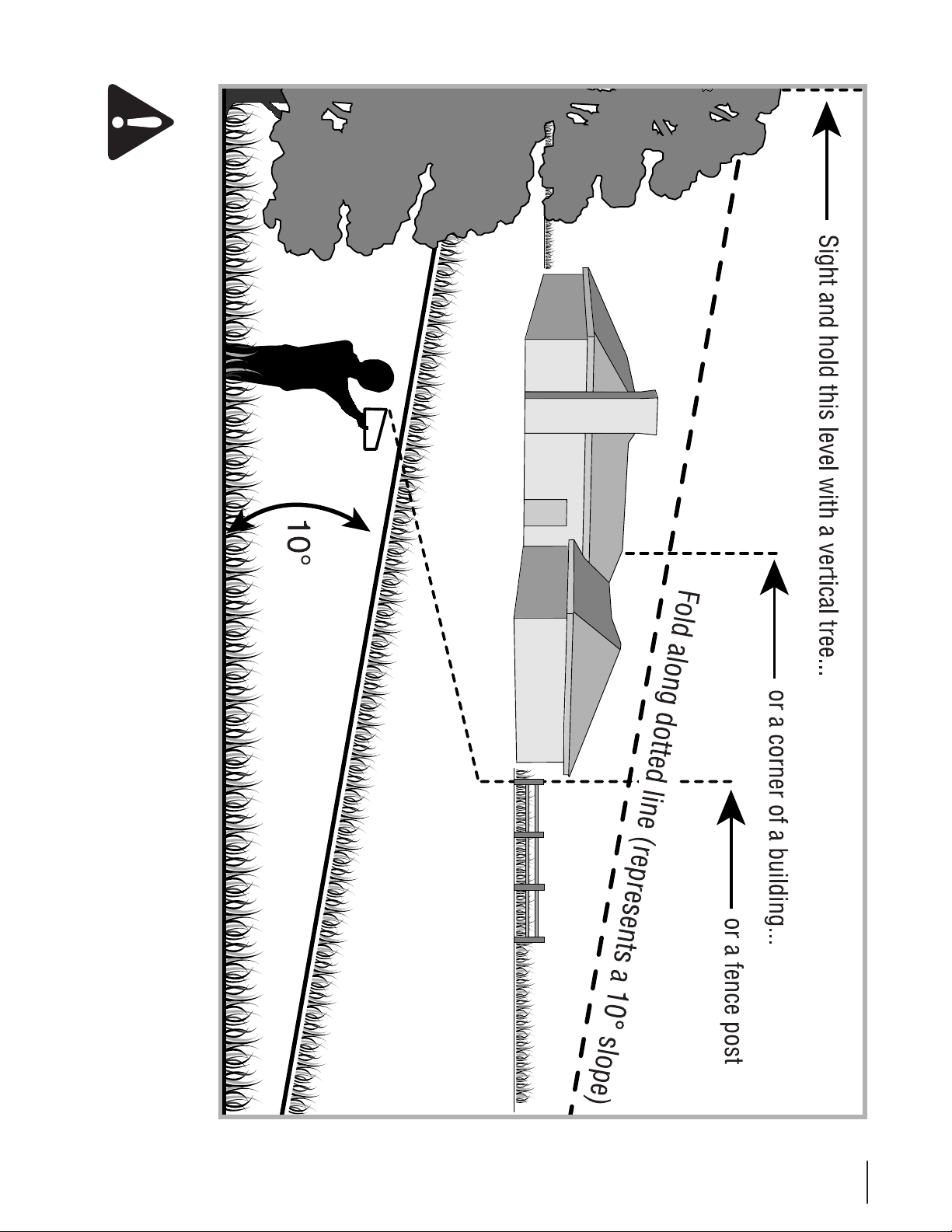
Use this page as a guide to determine slopes where you may not operate safely.
WARNING! Do not operate your wheelbarrow on such slopes. Do not operate on inclines with a slope in excess of 10
degrees (a rise of approximately 1-¾ feet every 10 feet). The wheelbarrow could overturn and cause serious injury. Operate
the wheelbarrow up and down slopes, never across the face of slopes.
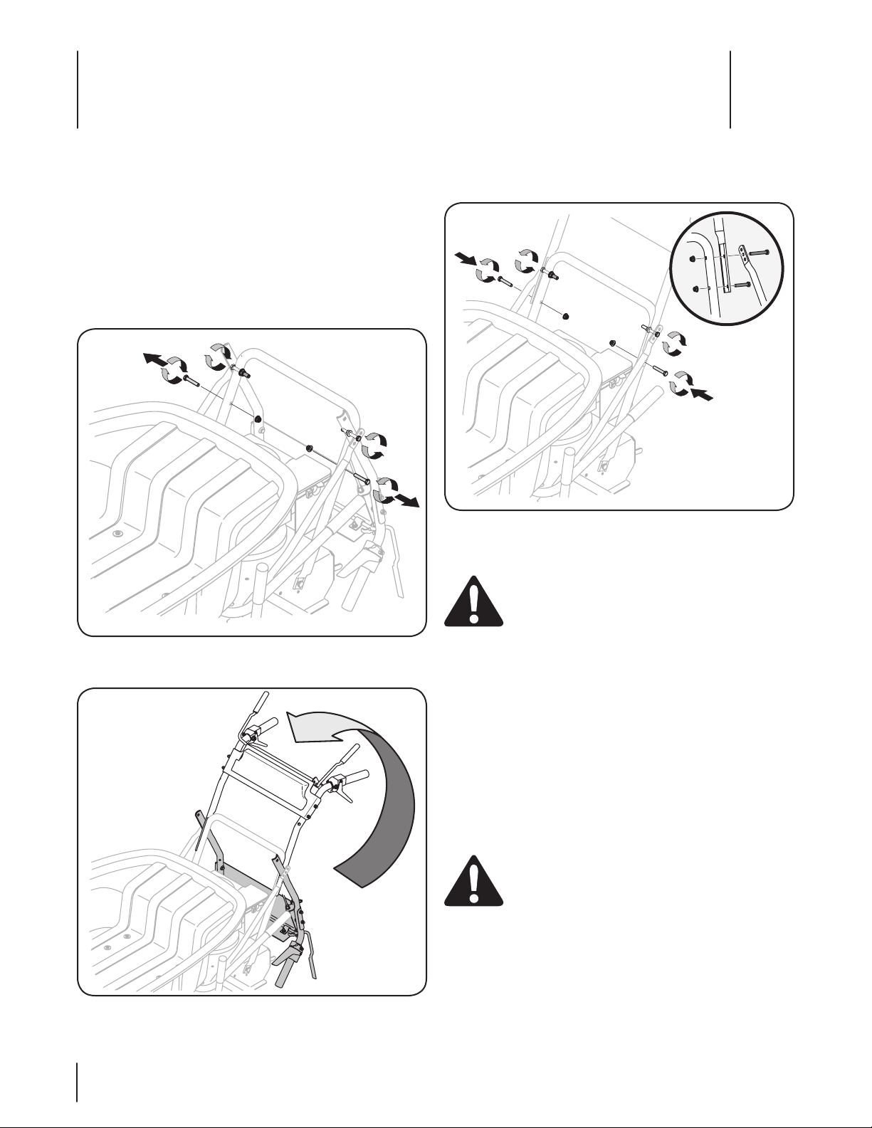
Insert and tighten the lower handle bolts into the c.
upper and lower handles. Tighten the upper handle
bolts. See Fig. 3-3.
Tire Pressure
WARNING! Under any circumstance do not exceed
manufacturer’s recommended tire pressure. Equal
tire pressure should be maintained at all times.
Excessive pressure when seating beads may cause
tire/rim assembly to burst with force sufficient to
cause serious injury. Refer to side wall of tire for
recommended pressure.
The recommended operating tire pressure is:
Approximately 30 psi for the small, rear tires•
Approximately 14 psi for the large, front tires•
IMPORTANT: Refer to the tire sidewall for exact tire
manufacturer’s recommended or maximum psi. Do not
overinflate. Uneven tire pressure could cause the wheelbarrow to
push at an angle.
Add Oil and Fuel
WARNING! Use extreme care when handling
gasoline. Gasoline is extremely flammable and the
vapors are explosive. Never fuel machine indoors or
while the engine is hot or running. Extinguish
cigarettes, cigars, pipes, and other sources of
ignition.
Service the engine with gasoline and oil as instructed in
the separate Engine Operator’s Manual packed with your
wheelbarrow. Read instructions carefully.
Unpacking and Assembly
Unscrew bolts around the lower edge of the crate and lift 1.
off the top half of the crate.
Cut and discard the cable tie securing the lower handle to 2.
the upper handle, and the nylon tags securing unit to the
crate.
To assemble the handle:3.
Remove the lower handle bolts, and loosen the bolts a.
securing upper handle to lower handle. See Fig. 3-1.
Fold up the upper handle. See Fig. 3-2.b.
Figure 3-1
Figure 3-2
Figure 3-3
Assembly & Set-Up
3
8
WARNING Read, understand, and follow all
instructions and warnings on the machine and in
this manual before operating.
Transmission Release Rod
The transmission release rod is located at the bottom left hand
edge of the wheelbarrow frame. Engaging the transmission
release rod will enable manual moving of the wheelbarrow.
Brake Release Lever
The brake release bail is located across the top of the handle
panel and controls the brake for the wheelbarrow. When not
held down, the brake release bail acts as a parking brake. When
held down, the bail releases the brake.
Forward Lever
The forward lever is located on the right hand side of the handle
panel. The forward lever is used to drive the wheelbarrow
forward.
Reverse Lever
The reverse lever is located on the left hand side of the handle
panel. The reverse lever is used to drive the wheelbarrow in
reverse.
Locking Lever & Lift Bar
The locking lever and lift bar are located on the left side of the
wheelbarrow and are used to operate the wheelbarrow bed.
Release the locking lever to unlock the bed, and push the lift bar
forward to unload the wheelbarrow bed contents.
Bed
The bed is located in the front of the wheelbarrow. The bed can
be emptied by pushing the lift bar forward, and locked in place
by the locking lever.
Note: Maximum load of the wheelbarrow is 500 lbs. on level
surfaces and 400 lbs. when operating on slopes.
Transmission
Release ON
Transmission
Release OFF
Brake Release Lever
Forward Lever
Reverse
Lever
Lift Bar
Locking
Lever
Bed
Stop Switch
Choke Control
Recoil Starter
Figure 4-1
Controls and Features
4
9

Engine
Stop Switch
The stop switch is located on the front of the engine. Turn to ON
to enable starting of the engine. Turn to OFF to stop the engine.
Choke Control
The choke control is located above the stop switch. Activating
the choke will close the choke plate on the carburetor and aid in
starting the engine.
Recoil Starter
The recoil starter is located on the engine below the handle
panel. Pull the recoil starter to start the unit.
10 se c t i O n 4— cO n t r O l s a n d fe a t u r e s
Starting Engine
WARNING: Be sure no one other than the operator
is standing near the wheelbarrow while starting
engine or operating wheelbarrow. Never run engine
indoors or in enclosed, poorly ventilated areas.
Engine exhaust contains carbon monoxide, an
odorless and deadly gas. Keep hands, feet, hair and
loose clothing away from any moving parts on
engine and wheelbarrow.
Set the ON/OFF switch to the ON position.1.
Set the choke lever to CHOKE position.2.
Pull the recoil starter lightly until resistance is felt, then pull 3.
rapidly to overcome compression, prevent kickback, and
start the engine. Repeat if necessary.
NOTE: Do not allow the recoil starter to snap back against
the rope guide.
Set the choke lever to the RUN position.4.
Stopping Engine
Set the stop switch to the OFF position.
Operating on Slopes
Refer to the SLOPE GAUGE in the Important Safe Operation
Practices section in the front of this manual to help determine
slopes where you may operate the wheelbarrow safely.
WARNING! Do not exceed a load of 400 lbs. on
slopes as the wheelbarrow may lose stability.
WARNING! Do not operate on inclines with a slope
in excess of 10 degrees (a rise of approximately 2
feet every 10 feet). The wheelbarrow could overturn
and cause serious injury.
Go up and down slopes, NEVER across.•
Exercise extreme caution when changing direction on •
slopes.
Watch for holes, ruts, bumps, rocks, or other hidden •
objects. Uneven terrain could overturn the machine. Tall
grass can hide obstacles.
Avoid turns when operating on a slope. If a turn must be •
made, turn down the slope. Turning up a slope greatly
increases the chance of a roll over.
Avoid stopping when going up and down slopes. If it is •
necessary to stop while going up a slope, start up smoothly
and carefully to reduce the possibility of flipping the
wheelbarrow over backward.
Minimize speed when going down slopes as wheelbarrow •
will accelerate with heavy loads.
Moving and Stopping
WARNING! Do not overload the wheelbarrow; the
maximum load on level surfaces is 500 lbs. When
operating on slopes, the maximum load is 400 lbs.
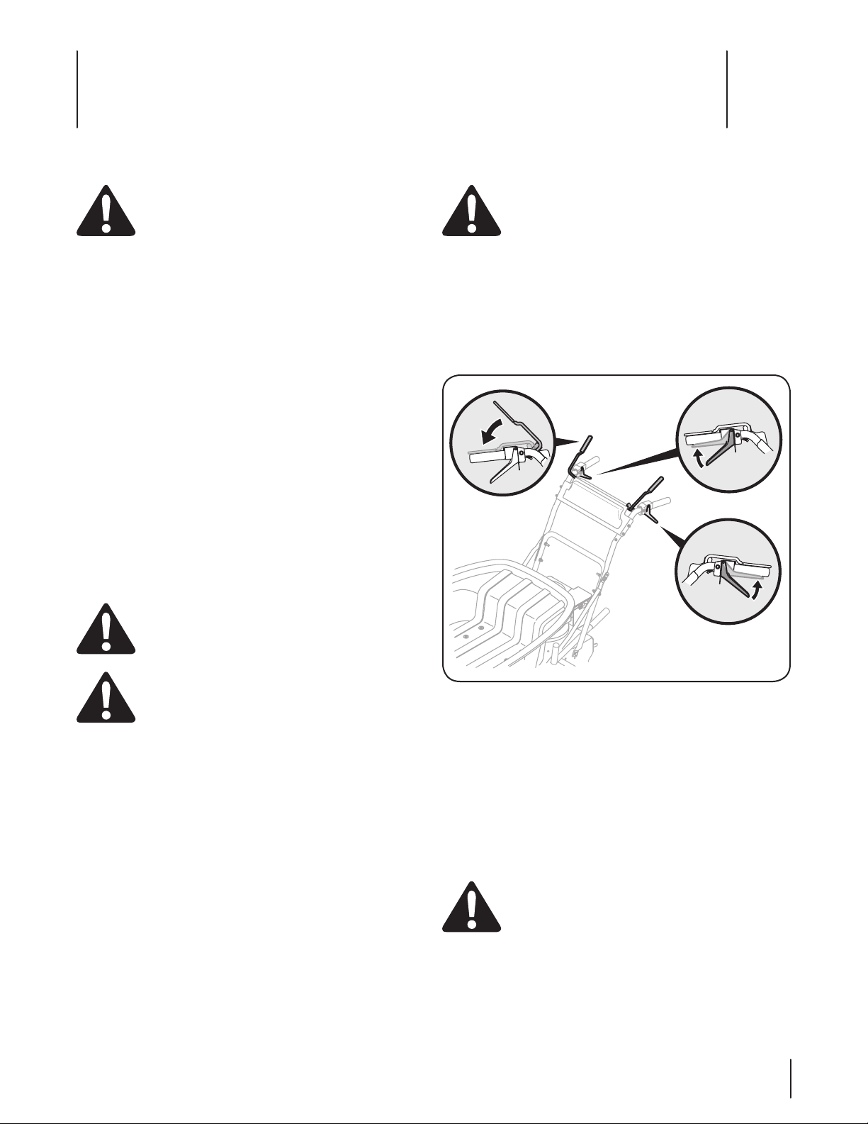
To move forward:
Squeeze the brake release lever. 1.
Squeeze the forward lever, while holding down the brake 2.
release lever. See Fig. 5-1.
NOTE: The wheelbarrow levers are pressure sensitive; squeezing
the forward lever tightly will move the wheelbarrow faster than if
the lever is loosely squeezed.
To move in reverse:
Squeeze the brake release lever.1.
Squeeze the reverse lever, while holding down the brake 2.
release lever. See Fig. 5-1.
NOTE: The wheelbarrow levers are pressure sensitive; squeezing
the reverse lever tightly will move the wheelbarrow faster than if
the lever is loosely squeezed.
To stop, slowly release the forward or reverse lever until the
wheelbarrow stops and disengage the brake release lever.
CAUTION! Releasing the brake release lever while
the wheelbarrow is moving will stop the
wheelbarrow suddenly, possibly displacing the
contents of the bed.
Brake
Forward
Reverse
Figure 5-1
Operation
5
11
Unloading
WARNING: Make sure the target unloading area is
clear before unloading the wheelbarrow.
IMPORTANT: Make sure the wheelbarrow is at a complete stop,
and release the brake release lever to lock the wheelbarrow in
place.
Note: Releasing the brake release lever while the wheelbarrow is
moving will suddenly stop the wheelbarrow, possibly displacing
the contents of the bed.
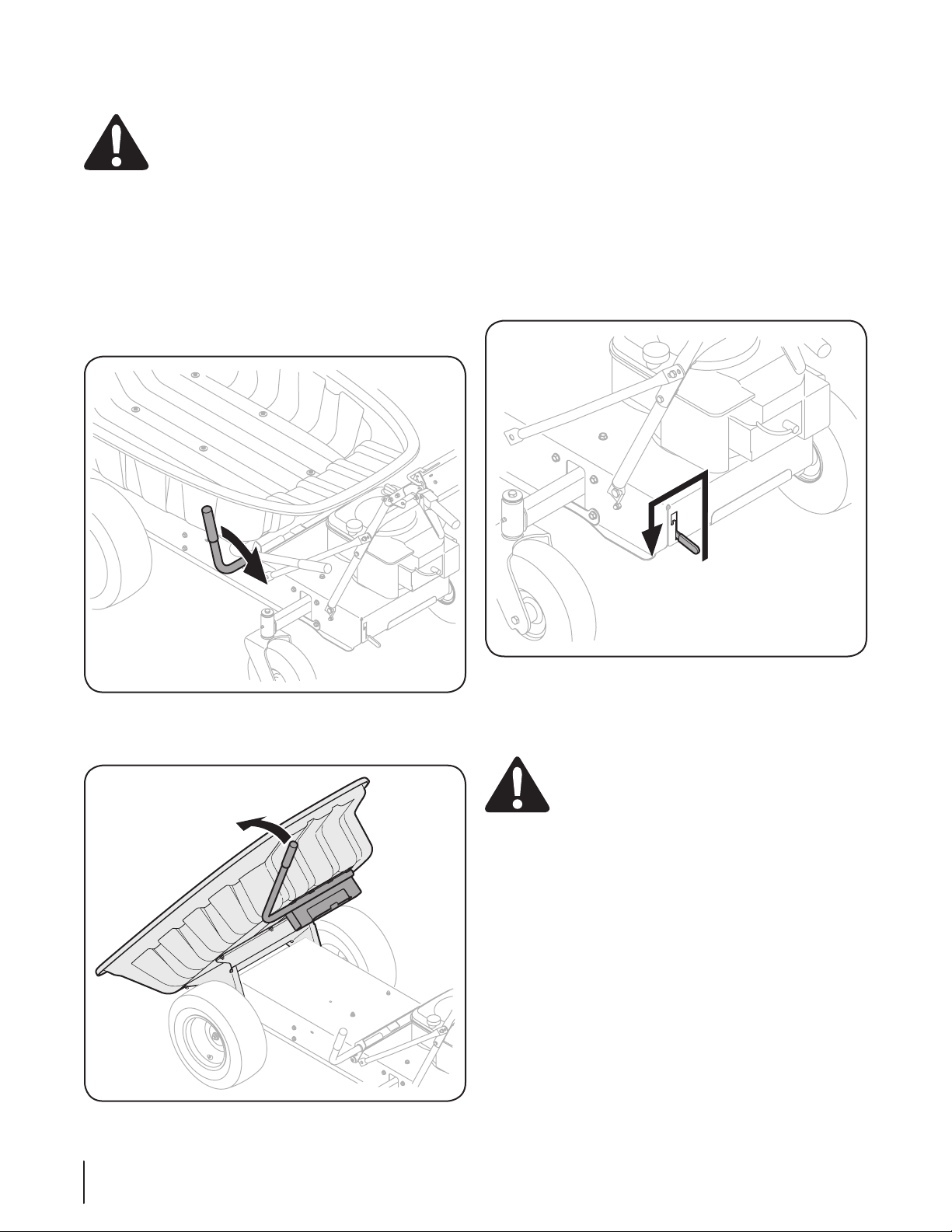
To unload the wheelbarrow:
Pull the locking lever toward the handle panel to unlock 1.
the wheelbarrow bed. See Fig. 5-2.
Push the lift bar towards the front of the wheelbarrow to 2.
unload contents of wheelbarrow. See Fig. 5-3.
Figure 5-2
Figure 5-3
IMPORTANT: Clear any debris that may interfere with the
locking mechanism.
Pull the lift bar towards the handle panel to return the bed 3.
to a flat position on the wheelbarrow.
Push down on the bed until the locking lever relatches.4.
IMPORTANT: Make sure the bed is locked before operating
wheelbarrow.
Moving With Engine Off
To manually move the wheelbarrow, lift the transmission release
rod up and slide to the left to set the transmission release rod in
the ON position. See Fig. 5-4.
Hold down the brake release lever and push the wheelbarrow.
To resume gas power, reset the transmission release rod to the
OFF position.
WARNING: Do not tow the wheelbarrow, even
with the transmission release rod in the ON position.
Serious transmission damage will result from doing
so.
Note: The wheelbarrow will not drive with the transmission
release ON.
Figure 5-4
12 se c t i O n 5— Op e r a t i O n

Maintenance Schedule
Before
Each use
Every
10 Hours
Every
25 Hours
Every
50 Hours
Every
100 Hours
Prior
to Storing
Check Engine Oil Level
P P
Check Air Filter for Dirty, Loose or Damaged Parts
P
Clean and Re-oil Air Filter’s Foam Precleaner
P
Replace Air Filter Element
P
Change Engine Oil and Replace Oil Filter
P
Lube Rear Axles
P P
Clean Engine Cooling Fins
P P
Check Spark Plug Condition & Gap
P P
Replace Fuel Filter
P
IMPORTANT: It is important to consult the specific engine Operator’s Manual included with this machine for detailed engine
maintenance procedures and intervals.
General Recommendations
Always observe safety rules when performing any maintenance.
The warranty on this wheelbarrow does not cover items •
that have been subjected to operator abuse or negligence.
To receive full value from warranty, operator must maintain
the wheelbarrow as instructed here.
All adjustments should be checked at least once each •
season.
Periodically check all fasteners and make sure these are •
tight.
WARNING: Always stop engine, disconnect spark
plug, and ground against engine before performing
any type of maintenance on your machine.
Engine
Refer to the Engine Operator’s Manual for engine maintenance
instructions.
Check engine oil level before each use as instructed in the Engine
Operator’s Manual packed with your unit. Follow the instructions
carefully.
Air Cleaner
Service the pre-cleaner and cartridge/air cleaner element as
instructed in the Engine Operator’s Manual packed with your
unit.
Spark Plug
The spark plug should be cleaned and the gap reset once a
season. Refer to the Engine Operator’s Manual for correct plug
type and gap specifications.
Maintenance & Adjustments
6
13
Engine Operator’s Manual packed with your unit.
IMPORTANT: Refer to the Engine Operator/Owner Manual
packed with your unit for information regarding the
quantity and proper viscosity of motor oil.
Adjustments
Brake Cable
If the wheelbarrow does not come to a complete stop when
the brake release lever is released, or if the wheelbarrow can
roll with the brake release lever released, the brake is in need of
adjustment. See an authorized Troy-Bilt Service dealer to have
your brakes properly adjusted.
Forward and Reverse Cable
When the forward or reverse levers are released, the control
levers should have very little slack. They should NOT be tight.
NOTE: If excessive slack is present in the forward or reverse
cables or if the wheelbarrow’s drive is disengaging intermittently
during operation, the cables may be in need of adjustment.
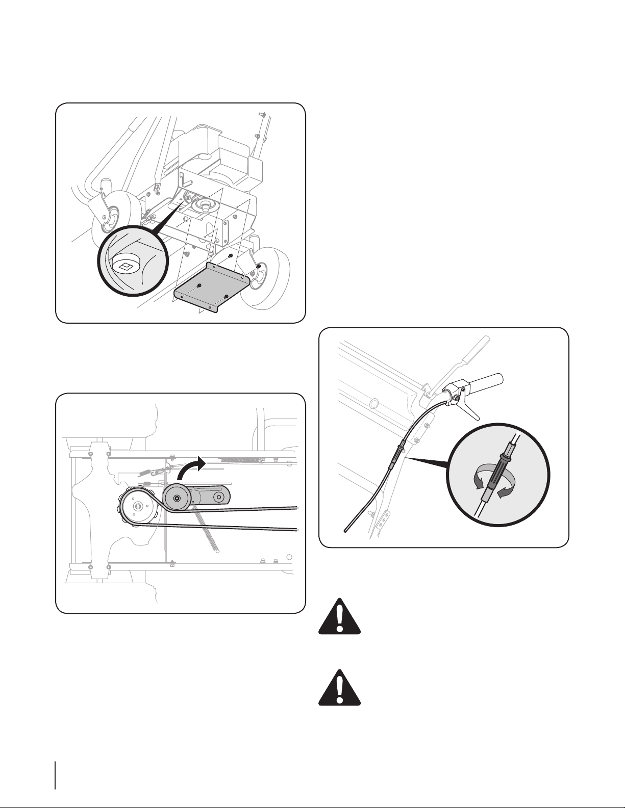
To tighten the forward and reverse controls, twist the applicable
cable adjustment clockwise. See Fig. 6-3.
To loosen the forward and reverse controls, twist the applicable
cable adjustment counter clockwise. See Fig. 6-3.
CAUTION: If the wheelbarrow drives with the
brake release lever engaged, but the forward and
reverse levers disengaged, the control cables are too
tight. Stop unit immediately and loosen control
cables.
CAUTION: When the forward or reverse levers are
released, the control levers should have very little
slack. They should NOT be tight.
Changing Engine Oil
To drain the oil, proceed as follows:
Unscrew belt cover found below the engine. See Fig. 6-1.1.
Pull the idler pulley at the front of the wheelbarrow to the 2.
left (pull towards the locking lever and lift bar). Pull the
drive belt down to remove from the idler pulley. See Fig.
6-2.
Remove the drive belt from the engine pulley. 3.
Unscrew the oil fill cap and remove the dipstick from the oil 4.
fill tube.
Remove drain plug and drain oil into a suitable container 5.
with a capacity of no less than 64 oz. See Fig. 6-1.
Replace drain plug, belt and belt cover.6.
Refill the engine with new motor oil as instructed in the 7.
Figure 6-1
Figure 6-3
Figure 6-2
14 se c t i O n 6— Ma i n t e n a n c e & ad j u s t M e n t s
Lubrication
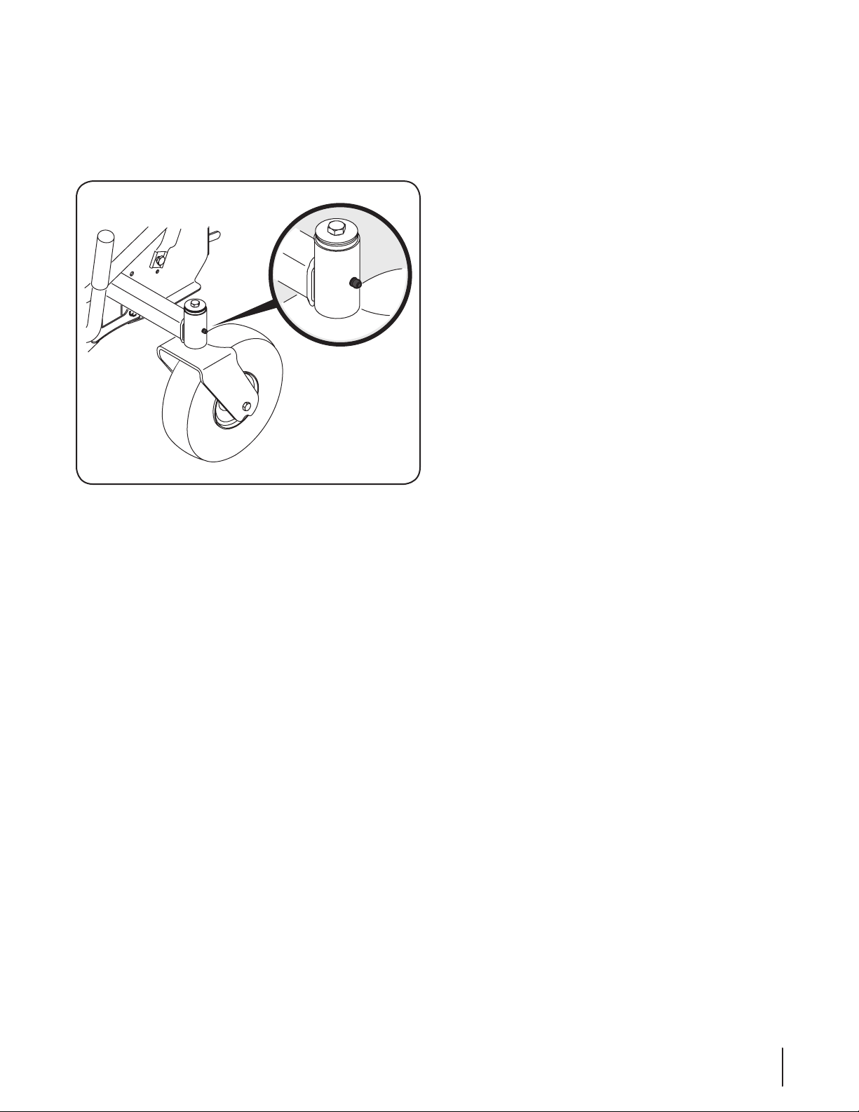
Rear Wheels
The rear axles are fitted with a grease fitting. See Figure 6-4.
Lubricate with a No. 2 multi-purpose grease applied with a
grease gun after every 25 hours of operation.
Pivot Points
Lubricate all the pivot points on the brake release lever, locking
lever, idler and bed pivot bracket at least once every 25 hours
with light oil.
Hydrostatic Transmission
The wheelbarrow is equipped with a a hydrostatic transmission
that is sealed and maintenance-free. Fluid levels cannot be
checked and fluid cannot be added or changed.
Figure 6-4
15se c t i O n 6 — Ma i n t e n a n c e & ad j u s t M e n t s

Tire Pressure
WARNING! Under any circumstance do not exceed
manufacturer’s recommended tire pressure. Equal
tire pressure should be maintained at all times.
Excessive pressure when seating beads may cause
tire/rim assembly to burst with force sufficient to
cause serious injury. Refer to side wall of tire for
recommended pressure.
The recommended operating tire pressure is:
Approximately 30 psi for the small, rear tires•
Approximately 14 psi for the large, front tires•
IMPORTANT: Refer to the tire sidewall for exact tire
manufacturer’s recommended or maximum psi. Do not
overinflate. Uneven tire pressure could cause the wheelbarrow to
push at an angle.
Off-Season Storage
The following steps should be taken to prepare your
wheelbarrow for storage.
Clean and lubricate wheelbarrow thoroughly as described •
in the lubrication instructions.
Do not use a pressure washer or garden hose to clean your •
unit.
Refer to Engine Operator’s Manual for correct engine •
storage instructions.
Store wheelbarrow in a dry, clean area. Do not store next to •
corrosive materials, such as fertilizer.
When storing any type of power equipment in a poorly
ventilated or metal storage shed, care should be taken to
rust-proof the equipment. Using a light oil or silicone, coat
the equipment, especially cables and all moving parts of your
wheelbarrow before storage.
Service
7
16

Problem Cause Remedy
Engine Fails to start Fuel tank emtpy or stale fuel.1.
Blocked fuel line.2.
Spark plug wire disconnected.3.
Faulty spark plug.4.
Choke is OFF.5.
Fill tank with clean, fresh gasoline.1.
Clean fuel line.2.
Connect wire to spark plug.3.
Clean spark plug, readjust gap, or replace.4.
Unless the engine is warm, move choke lever 5.
to the choke ON position.
Engine runs erratically Engine running on choke.1.
Fuel line blocked or stale fuel. 2.
Water or dirt in fuel system.3.
Carburetor out of adjustment.4.
Move choke lever to RUN position.1.
Clean fuel line and fill tank with clean, fresh 2.
gasoline.
Drain fuel tank. Refill with fresh fuel.3.
See an authorized service dealer.4.
Engine overheats Engine oil level low.1.
Carburetor out of adjustment.2.
Add oil to engine.1.
See an authorized service dealer.2.
Loss of power Spark plug wire loose.1.
Vent in gas cap plugged.2.
Firmly connect spark plug wire.1.
Clear vent.2.
Unit will not drive Transmission release is ON. 1.
Drive belt is broken or worn. 2.
Brake is engaged.3.
Release control levers and move transmission 1.
release to the OFF position.
Turn unit off, release brake release lever, and 2.
inspect belt for cracks or wear.
Hold down brake release lever while 3.
squeezing the forward or reverse lever.
Troubleshooting
8
17

Notes
9
18

19se c t i O n 11 — nO t e s
20
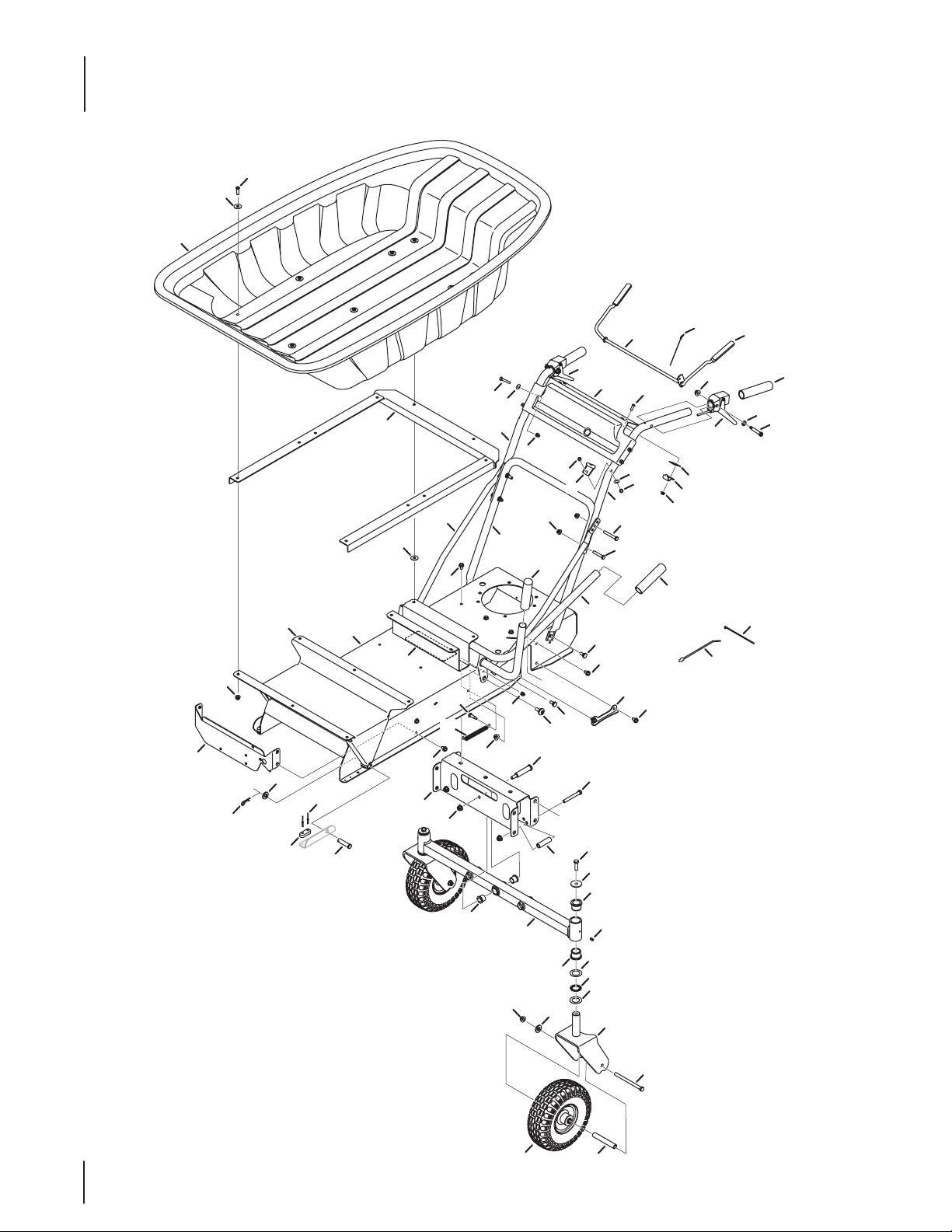
Bed, Frame, and Rear Wheel Assembly
33
41
36
49
50
46
59
16
55
47
3
1
27
11
2
6
13
54
48
5
4
63
15
11
10
22
20
19
58
61
59
62
60
56
65
57
17
60
45
35
39
48
7
4
66
63
7
21
34
8
53
8
48
42
42
37
52
30
6
26
25
6
64
51
23
14
29
24
11
12
31
A
7
A
9
44
18
43
38
18
32
48
40
28

21
Ref.
Part Number Description
1 681-04154-0637 Brake Bail Assembly
2 710-0924 Screw, ¼-20 x 0.750
3 710-0395 Hex Head Screw, ⁵⁄₁₆-18 x 2.25
4 710-0606 Hex Head Screw, ¼-20 x 1.50
5 710-3180 Hex Head Screw, ⁵⁄₁₆-18 x 1.75
6 712-04063 Flangelock Nut, ⁵⁄₁₆-18
7 712-04064 Flangelock Nut, ¼-20
8 712-04065 Flangelock Nut, ³⁄₈-16
9 912-0442 Cap Lock Nut, ¼-20
10 720-0270A Reverse Handle Grip
11 720-0274 Grip, 1.0 ID x 5.0 LG
12 926-0154 Cable Tie, 7.5 LG, Push Mount
13 726 -0317 Cable Tie, 8.5 LG
14 735-04182 Damper Pad
15 936-0169 Washer, Lock, ³⁄₈
16 750-05255 Spacer, .375 x .625 x 4.05
17 741-3083 Thrust Bearing Needle, 1.00 x 1.562
18 938-0140 Shield Screw, .435 x .178 - 5/16 x .56
19 738-04402 Socket Head Screw, ⁵⁄₁₆-18 x .375
20 946-04592 Forward Cable
21 946-04595 Reverse Cable
22 946-04598 Brake Release Cable
23 749-04330-0637 Lower Handle
24 749-04331-0637 Upper Handle, LH
25 749-04332-0637 Upper Handle, RH
26 749-04333-0637 Handle Adjuster Brace Tube
27 781-04360-0638 Handle Panel
28 781-04373-0637 Cable Mounting Bracket, LH
29 786-0098-0637 Retainer Bracket, RH
30 681-04133-0638 Pivot Bed Bracket Assembly
31 681-04155-0638 Bed Handle Assembly
32 681-04158-0638 Lock Bracket Assembly
33 710-1669 Screw, ⁵⁄₁₆-18 x 1.00
Ref.
Part Number Description
34 711- 0 5217 Clevis Pin, .500 x 2.00
35 914-0145 Click Pin, .092 x 1.64 LG
36 728-04041 Rivet, .125 DIA x .625
37 931-06908 Bed
38 732-04579 Extension Spring, .60 OD x 6.44 LG
39 735 -04172 Bumper Pad
40 735-04173 Rubber Pad
41 936-0326 Washer, Flat, .510 x 1.000 x .125
42 736-3078 Washer, Flat, .344 x 1.00 x .063
43 738 -04012A Screw, Shoulder, ³⁄₈-16 x .625 x .145
44 938-3141 Screw, Shoulder, ¼-20 x .31 x .75
45 781-04335-0638 Transmission Support Bracket
46 681-04146-0638 Front Axle Assembly
47 710-0521 Hex Head Screw, ³⁄₈-16 x 3.00
48 710-0604A Screw, ⁵⁄₁₆-18 x 0.625
49 738-04216A Shoulder Bolt, ³⁄₈-16 x .625 x 2.515
50 941-0353 Bronze Flange Bearing, .630 ID
51 750-05156 Spacer Tube, .385 x .625 x 2.250
52 781-04329-0638 Frame
53 781-04348-0638 Pivot Mount Bracket
54 781-04379-0638 Frame Brace Bracket
55 634-04584 Wheel Assembly, 10.0 x 3.5
56 681-04165-0638 10" Wheel Caster Assembly
57 710- 0615A Hex Head Screw, ³⁄₈-16 x 5.00
58 710-0879 Hex Head Screw, ³⁄₈-24 x 1.25
59 731-05500 Flange, Bearing, 1.00 ID x 1.246 OD
60 936-0163 Washer, Flat, 1.03 x 1.62 x .03
61 736-0234 Washer, Flat, .385 x 1.5 x .075
62 937-3000 Drive Lube Fitting, ³⁄₁₆
63 736-0173 Washer, Flat, .28 x .74 x .063
64 712-0266A Nut, Jamlock, ³⁄₈-16
65 936-0185 Washer, Flat, .375 x .738 x .063
66 681-04174 Bed Frame Assembly
Bed, Frame, and Rear Wheel Assembly
22
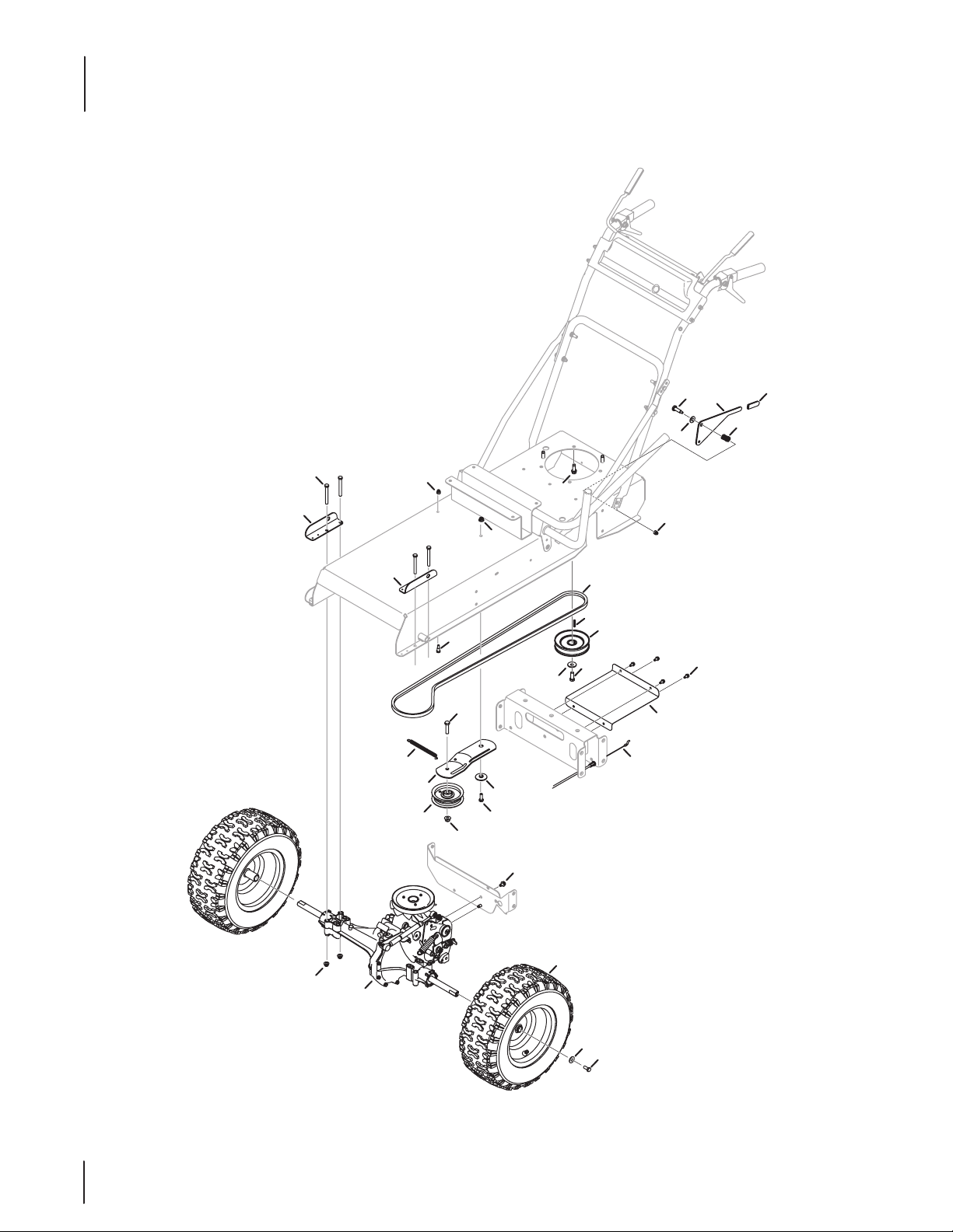
Drive Assembly
21
13
5
23
14
26
25
9
4
7
20
28
6
19
27
11
2
30
17
29
1
13
11
32
24
22
10
12
3
18
8
16
15
31

23
Ref. Part Number Description
1 781-04380-0638 Support Bracket, LH
2 918-04845 Transmission Assembly w/ Damper
727-04291 Cylinder, Damper
732-04293 Spring, .75 OD X 3.240
3 710- 0176 Hex Head Screw, ⁵⁄₁₆-18 x 2.75
4 710-0520 Hex Head Screw, ³⁄₈-16 x 1.50
5 710-0599 Screw, ¼-20 x 0.500
6 710-0627 Hex Head Screw, ⁵⁄₁₆-24 x .750
7 710-0607 Screw, ⁵⁄₁₆-18 x 0.500
8 710-0654A Screw, ³⁄₈-16 x 1.000
9 710-1039 Hex Head Screw, ³⁄₈-24 x 1.00
10 710-3038 Hex Head Screw, ⁵⁄₁₆-18 x .875
11 712- 04063 Flangelock Nut, ⁵⁄₁₆-18
12 712- 04065 Flangelock Nut, ³⁄₈-16
13 912-04 42 Cap Lock Nut, ¼-20
14 914-0105 Square Key, ³⁄₁₆ x 1.00
15 720-04008 Shift Handle Grip
16 732-0193 Compression Spring, .39 x .60 x .88
17 732-04639 Extension Spring, .55 DIA x 6.25 LG
18 936-0267 Washer, Flat, .385 x .87 x .06
19 936-0452 Washer, Bell, .396 x 1.140 x .095
20 634-04135-0911 X-Trac Wheel, Complete, 16 x 6.5 x 8
21 738- 04125 Screw, Shield, .374 DIA. x 1.05 LG.
22 738-04166 Spacer, Shoulder, .5000 x .1475
23 738-04395 Screw, Shoulder, ¼-20 x .31 x .50
24 946-04623 Transmission Cable
25 954-04165 V-Belt, 4L x 78 LG POLY
26 756-04378 Engine Pulley
27 756-0627D Idler Pulley, 3.50 DIA.
28 736-0242 Washer, Bell, .340 x .872 x .060
29 781-04347-0638 Support Bracket, RH
30 781-04349-0637 Idler Bracket
31 781-04376-0637 Transmission Release Bracket
32 781-04377-0638 Pulley Guard
Drive Assembly

MANUFACTURER’S LIMITED WARRANTY FOR
GDOC-100216 REV. A
The limited warranty set forth below is given by Troy-Bilt LLC with
respect to new merchandise purchased and used in the United States
and/or its territories and possessions, and by MTD Products Limited
with respect to new merchandise purchased and used in Canada and/
or its territories and possessions (either entity respectively, “Troy-
Bilt”).
Troy-Bilt warrants this product (excluding its Normal Wear Parts and
Attachments as described below) against defects in material and
workmanship for a period of two (2) years commencing on the date
of original purchase and will, at its option, repair or replace, free of
charge, any part found to be defective in materials or workmanship.
This limited warranty shall only apply if this product has been
operated and maintained in accordance with the Operator’s Manual
furnished with the product, and has not been subject to misuse,
abuse, commercial use, neglect, accident, improper maintenance,
alteration, vandalism, theft, fire, water, or damage because of other
peril or natural disaster. Damage resulting from the installation or use
of any part, accessory or attachment not approved by Troy-Bilt for use
with the product(s) covered by this manual will void your warranty as
to any resulting damage.
Normal Wear Parts are warranted to be free from defects in material
and workmanship for a period of thirty (30) days from the date of
purchase. Normal wear parts include, but are not limited to items
such as: batteries, belts, bed and tires.
Attachments — Troy-Bilt warrants attachments for this product
against defects in material and workmanship for a period of one (1)
year, commencing on the date of the attachment’s original purchase
or lease.
HOW TO OBTAIN SERVICE: Warranty service is available, WITH
PROOF OF PURCHASE, through your local authorized service dealer.
To locate the dealer in your area:
In the U.S.A.
Check your Yellow Pages, contact Troy-Bilt LLC at P.O. Box 361131,
Cleveland, Ohio 44136-0019 or call 1-866-840-6483 or 1- 330-558-
7220.
In Canada
Contact MTD Products Limited, Kitchener, ON N2G 4J1, call 1-800-
668-1238 or log on to our Web site at www.mtdcanada.com.
This warranty is subject to the following limitations:
a. If your product included a separate engine manufacturer’s
written warranty, that warranty is the sole and exclusive warranty
applicable to the engine components of your product, and all other
components shall be warranted under the terms and conditions of
this warranty. Please refer to any such applicable manufacturer’s
warranty for its terms and conditions.
b. Routine maintenance items such as lubricants, filters, tune-ups,
brake adjustments, clutch adjustments, and normal deterioration
of the exterior finish due to use or exposure are not covered.
c. Service completed by someone other than an authorized service
dealer is not covered.
d. Troy-Bilt does not extend any warranty for products sold or
exported outside of the United States and/or Canada, and their
respective possessions and territories, except those sold through
Troy-Bilt’s authorized channels of export distribution.
e. Replacement parts that are not genuine Troy-Bilt parts are not
warranted.
f. Transportation charges and service calls are not covered.
g. Troy-Bilt does not warrant this product for commercial use.
Except as expressly set forth herein, there are no other
warranties, express or implied, including any implied warranty
of merchantability of fitness for any particular purpose. Beyond
this document, no other express warranty, whether written or oral
given by any person or entity other than Troy-Bilt , including a
dealer or retailer, with respect to any product, shall bind Troy-Bilt .
The exclusive remedy hereunder is the repair or replacement of the
product as set forth above.
The provisions as set forth in this warranty (and any applicable
engine warranty provided by the engine manufacturer) provide the
sole and exclusive remedy arising from the sale. Troy-Bilt shall not
be liable for incidental or consequential loss or damage including,
without limitation, expenses incurred for substitute or replacement
lawn care services or for rental expenses to temporarily replace a
warranted product.
Some states do not allow the exclusion or limitation of incidental
or consequential damages, or limitations on how long an implied
warranty lasts, so the above exclusions or limitations may not apply
to you.
In no event shall recovery of any kind be greater than the amount of
the purchase price of the product sold. Alteration of safety features of
the product shall void this warranty. You assume the risk and liability
for loss, damage, or injury to you and your property and/or to others
and their property arising out of the misuse or inability to use the
product.
This limited warranty shall not extend to anyone other than the
original purchaser or to the person for whom it was purchased as a
gift.
HOW STATE LAW RELATES TO THIS WARRANTY: This limited
warranty gives you specific legal rights, and you may also have other
rights which vary from state to state.
IMPORTANT: Owner must present Original Proof of Purchase to
obtain warranty coverage.
Troy-Bilt LLC, P.O. BOX 361131 CLEVELAND, OHIO 44136-0019; Phone: 1-866-840-6483, 1-330-558-7220
MTD Canada Limited - KITCHENER, ON N2G 4J1; Phone 1-800-668-1238