
Installation Manual
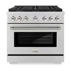
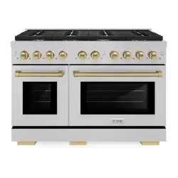
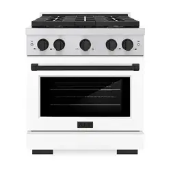
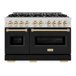
GAS RANGES
SGR MODELS
www.zlinekitchen.com

ZLINE Kitchen and Bath provides Attainable Luxury, where the kitchen and bath of your dreams
is never out of reach. Through our unique designs and unparalleled quality, we’re dedicated to
providing you an elevated experience in the heart of your home. With an endless selection of
features and finishes, our inspiration is your reality.
ZLINE is fueled by a passion for innovation; A relentless pursuit of bringing the highest end luxury
designs and professional features into everyone’s homes. Because we continually strive to improve
our products, we may change specifications and designs without prior notice.
WARNING: This product can expose you to chemicals including nickel, which is known to the
State of California to cause cancer. For more information, go to www.P65Warnings.ca.gov.

IMPORTANT SAFETY INFORMATION . . . . . . . . . . . . . . . . . . . 1
Gas Safety . . . . . . . . . . . . . . . . . . . . . . . . . . . . . . . . . . . . . 1
Electric And Gas Safety . . . . . . . . . . . . . . . . . . . . . . . . . . . . . . 6
Cooktop Safety . . . . . . . . . . . . . . . . . . . . . . . . . . . . . . . . . . 9
Ventilation Safety . . . . . . . . . . . . . . . . . . . . . . . . . . . . . . . . 13
Gas Supply And Electrical Connection . . . . . . . . . . . . . . . . . . . . . 16
BEFORE INSTALLATION . . . . . . . . . . . . . . . . . . . . . . . . . . . . . . 16
Product Specifications . . . . . . . . . . . . . . . . . . . . . . . . . . . . . . 21
Pre-Installation Specifications And Instructions . . . . . . . . . . . . . . . . 23
INSTALLATION . . . . . . . . . . . . . . . . . . . . . . . . . . . . . . . . . . . . .25
Gas Connection . . . . . . . . . . . . . . . . . . . . . . . . . . . . . . . . . 28
Liquid Propane Gas Conversion Procedure (Optional) . . . . . . . . . . . . 31
Installing The Anti-Tip Device . . . . . . . . . . . . . . . . . . . . . . . . . . 42
WARRANTY . . . . . . . . . . . . . . . . . . . . . . . . . . . . . . . . . . . . . . . .45
TABLE OF CONTENTS
1
GAS SAFETY
WARNING
WARNING: If the information in these
instructions is not followed exactly, a fire
or explosion may result causing property
damage, personal injury or death.
• Do not store or use gasoline or other flammable vapors and liquids in the vicinity
of this or any other appliance.
• WHAT TO DO IF YOU SMELL GAS
• Do not try to light any appliance.
• Do not touch any electrical switch.
• Do not use any phone in your building.
• Immediately call your gas supplier from a neighbor’s phone. Follow the gas
supplier’s instructions.
• If you cannot reach your gas supplier, call the fire department.
• Installation and service must be performed by a qualified installer, service agency
or the gas supplier.
IMPORTANT SAFETY INFORMATION
Gas Safety
2
Gas Safety
IMPORTANT SAFETY INSTRUCTIONS
AVERTISSEMENT
AVERTISSEMENT : Le non-respect à
la lettre de ces instructions peut causer
un incendie ou une explosion, qui
pourrait entraîner des dommages
matériels, desblessures ou la mort
• Ne pas entreposer ou utiliser d’essence ou tout autre liquide ou gaz
inflammable à proximité de cet appareil ou de tout autre appareil.
• EN PRÉSENCE D’UNE ODEUR DE GAZ :
• Ne tenter d’allumer aucun appareil ;
• Ne toucher à aucun commutateur électrique ;
• N’utiliser aucun téléphone dans l’immeuble ;
• Appeler immédiatement le fournisseur de gaz à partir d’un téléphone situé
à l’extérieur de l’immeuble ; Suivre les instructions du fournisseur de gaz ;
• S’il est impossible de joindre le fournisseur de gaz, appeler le service
des incendies.
• L’installation et la réparation doivent être effectuées par un installateur
ou une agence de réparation ayant les qualifications requises ou par le
fournisseur de gaz.
3
Gas Safety
IMPORTANT SAFETY INSTRUCTIONS
WARNING
WARNING:
Never Operate the Top Surface Cooking Section of this Appliance Unattended.
• Failure to follow this warning statement could result in fire, explosion, or burn
hazard that could cause property damage, personal injury, or death.
• If a fire should occur, keep away from the appliance and immediately call
your fire department. DO NOT ATTEMPT TO EXTINGUISH AN OIL/GREASE
FIRE WITH WATER.
ATTENTION
ATTENTION :
Ne faites jamais fonctionner la surface de cuisson, sur le dessus de cet appareil, sans
surveillance.
• Le non-respect de cette mise en garde pourrait entraîner un incendie, une
explosion ou un risque de brûlure et ainsi causer des dommages matériels, des
blessures ou la mort.
• Si l’appareil prend feu, tenez-vous à l’écart et appelez immédiatement votre
service des incendies. NE TENTEZ JAMAIS D’ÉTEINDRE UN FEU DE GRAISSE
OU D’HUILE EN L’ASPERGEANT D’EAU.
4
WARNING
WARNING: Never use this appliance as a space heater to heat or
warm the room. Doing so may result in carbon monoxide poisoning
and overheating. Never use the top of the range or the interior of the
oven as a storage areas, as items could melt or ignite, increasing the
risk of fire, damage, and/or serious injury.
AVERTISSEMENT
AVERTISSEMENT: Ne JAMAIS utiliser cet appareil électroménager en
guise de chaufferette. Le fait de chauffer une pièce ainsi peut entraîner un
empoisonnement au monoxyde de carbone ou une surchauffe du four.
WARNING
WARNING: NEVER cover any slots, holes or passages in the oven
bottom or cover an entire rack with materials such as aluminum foil.
Doing so blocks airflow through the oven and may cause carbon
monoxide poisoning. Aluminum foil linings may also trap heat, causing
a fire hazard.
AVERTISSEMENT
AVERTISSEMENT:Ne JAMAIS recouvrir une fente, un trou ou une
conduite dans le fond du four ni recouvrir entièrement une grille d’un
matériau comme du papier d’aluminium. Un tel revêtement bloque la
circulation d’air dans le four, ce qui peut entraîner un empoisonnement
au monoxyde de carbone. De plus, le papier d’aluminium peut
emprisonner la chaleur, ce qui risque de provoquer un incendie.
IMPORTANT SAFETY INFORMATION
Gas Safety

5
IMPORTANT SAFETY INFORMATION
• Before beginning installation, please read and follow these important instructions for the
safety of your home and the people living in it.
• The manufacturer will not be responsible for any damage to property or to persons
caused by incorrect installation, improper use of the appliance, or failure to heed the
warnings listed.
• The manufacturer reserves the right to make changes to its products when considered
necessary and useful, without affecting the essential safety and operating characteristics.
• This appliance has been designed for non-commercial, domestic use only.
• Please observe all local, state, and national codes and ordinances. Please ensure the
range is properly grounded. The plug should always be accessible.
• The installer should leave these instructions with the consumer who should retain for local
inspectors’ use and for future reference.
• This manual does not cover all possible conditions that may occur during installation
and/or operation. Always contact a qualified service technician or the manufacturer
about problems you may not understand.
WARNING
Installation and service on this product must only be conducted by a qualified
installer, service agency, or gas supplier.
• The installation of appliance designed for manufactured (mobile) home installation must
conform with the Manufactured Home Construction and Safety Standard, Title 24CFR,
Part 3280 [formerly the Federal Standard for Mobile Home Construction and Safety,
Title 24, HUD (Part280)] or with local codes where applicable.
• Installation of any gas-fired equipment should be made by a licensed plumber or gas
fitter. A manual gas shut-off valve must be installed in the gas supply line for safety and
ease of service.
• Please ensure that the altitude of your home is conducive for the use of gas cooking
products. If the product is installed at higher altitudes above sea level, you may experience
issues with gas pressure that will affect product performance. Please consult your local
gas company for recommendations before purchasing or installing.
Gas Safety
6
Electrical Safety
IMPORTANT SAFETY INFORMATION
IMPORTANT SAFETY ALERTS
DANGER
DANGER: When you see this symbol in the instructions, it indicates a hazardous
situation which, if not avoided, could result in death or serious injury.
WARNING
WARNING: When you see this symbol in the instructions, it indicates a hazardous
situation which, if not avoided, could result in minor or moderate injury.
DANGER
USE CARE WHEN UNPACKING THE PRODUCT
• Remove all tape and packaging before using the appliance, including plastic zip ties
securing the oven racks.
• Carefully dispose of the product’s shipping box, plastic bags, and all other packing
materials after the appliance is unpacked.
• Boxes covered with rugs, bedspreads, sheets, or other materials can become air-tight
chambers. Never allow children to play with packaging material.
• Remove all staples from the box. Staples can cause cuts and destroy finishes if they come
in contact with other appliances or furniture.
• Do not remove the model/serial plate attached to the appliance; doing so will not only
void the product warranty, it will limit the ability for future service to be conducted on the
range in an effective manner.
ELECTRIC AND GAS SAFETY
WARNING
• Be sure your appliance is properly installed and grounded by a qualified technician
in accordance with all local codes and ordinances and with the National Fuel Gas
Code ANSI Z223.1—latest edition and the National Electrical Code ANSI/NFPA No.
70—latest edition in United States, or CAN/CGA B149.1, B149.2, and the Canadian
Electrical Code, Part 1, in Canada.
• Gas leaks cannot always be detected by smell. As such, gas suppliers recommend that
you use a gas detector approved by UL or CSA. For more information, contact your
gas supplier.
• If a gas leak is detected, refer to the “WHAT TO DO IF YOU SMELL GAS”
alert on page 1.

7
Installation Safety
IMPORTANT SAFETY INFORMATION
• Installation and service on this product must be performed by a qualified installer,
servicer, or gas supplier. Ask the manufacturer to recommend a qualified technician and
authorized repair service in your area.
• Know how to shut off gas supply at the meter and disconnect the electrical power to the
appliance at the circuit breaker or fuse box in case of an emergency. Installers should
also show appliance owners the location of the appliance gas shut-off valve and how
to shut it off if necessary.
• Do not repair or replace any part of the appliance unless specifically recommended in
this manual. All other servicing should be done only by a qualified technician. This may
reduce the risk of personal injury and damage to the appliance.
DANGER
Always disconnect gas and power when servicing this product, especially for
larger-scale repairs impacting important appliance functionality; failure to do
so increases the risk of fire, explosion, injury, or death.
INSTALLATION SAFETY
• Never modify or alter the construction of the appliance by removing panels, wire covers,
or any other part of the product.
• Injuries may result from the misuse of appliance doors such as stepping, leaning, or
sitting on the doors.
• If the appliance is located near a window, NEVER hang long curtains or paper blinds
on that window. They could blow over the surface burners and ignite, potentially causing
a fire hazard.
• Ensure the kitchen or room where the appliance is installed is well ventilated by
keeping the air intakes open and in good working order and/or by installing a range
hood above the unit. It’s recommended a hood is installed between 30" and 36"
(762 mm and 914 mm) above the cooktop to allow for optimal air flow.
WARNING
An air curtain or other overhead range/range top hood, which operates
by blowing downward airflow onto the range, shall not be used/installed
in conjunction with this gas range.
8
IMPORTANT SAFETY INFORMATION
• If the appliance is used intensively for a long time, the effectiveness of the ventilation will
have to be increased, for example by opening a window or increasing the power of the
range hood operating above.
• Flammable materials and liquids should not be stored on the appliance or near surface
units. This includes paper, plastic, and cloth items, as well as cookbooks, plastic ware,
and towels. Do not store explosives such as aerosol cans on or near the appliance.
Flammable materials may explode and result in fire or property damage.
• Keep the appliance area clear and free from combustible materials, gasoline, and other
flammable vapors and liquids.
• Flammable materials should not be stored in the oven or near surface units.
IN THE STATE OF MASSACHUSETTS, THE FOLLOWING INSTALLATION
INSTRUCTIONS APPLY
• Installations and repairs must be performed by a qualified or licensed contractor,
plumber, or gas fitter licensed by the State of Massachusetts.
• If using a ball valve, it must be a T-handle type.
• A flexible gas connector, when used, must not exceed 3' (914 mm).
WARNING
STATE OF CALIFORNIA PROPOSITION 65 WARNINGS
• The California Safe Drinking Water and Toxic Enforcement Act requires the Governor of
California to publish a list of substances known to the state to cause birth defects or other
reproductive harm and requires businesses to warn customers of potential exposure to
such substances.
• Gas appliances can cause minor exposure to at least four main substances — benzene,
carbon monoxide, formaldehyde, and soot — caused primarily by the incomplete
combustion of natural gas or liquid propane fuels.
• Properly adjusted burners, indicated by a bluish rather than yellow flame, will minimize
incomplete combustion. Exposure to these substances can also be minimized by venting
with an open window or by using a ventilation fan or range hood.
Installation Safety

9
IMPORTANT SAFETY INFORMATION
COOKTOP SAFETY
DANGER
• Do not store items of interest to children in the cabinets above the appliance or on the
back splash of appliance.
• Children should not be left alone or unattended in the area where the appliance is in use.
Do not allow children to climb, play, sit, or stand on or around any part of the appliance.
Children climbing on the appliance to reach items could be seriously burned or injured.
• DO NOT TOUCH THE COOKING SURFACE, BURNERS, GRATES, OR ANY AREAS
NEAR THEM. Surface burners or other parts of the range may be hot even though flames
are not visible.
• Areas near surface burners or throughout the appliance may become hot enough to
cause burns. During and after use, do not touch, or let clothing or other flammable
materials touch, these areas until they have had sufficient time to cool.
• Do not wear loose-fitting or hanging garments while using the appliance. Do not let
clothing or other flammable materials contact hot surfaces.
• Smother grease fires with a pan lid, or use baking soda, a dry chemical, or foam-type
extinguisher. Use an extinguisher ONLY if:
• You have a Class A, B, or C extinguisher and you know how to operate it.
• The fire is small and contained in the area where it is started.
• The fire department is being/has been called.
• You can fight the fire with your back to an exit.
• When heating fat or grease, watch it closely. Fat or grease may catch fire if allowed to
become too hot.
• Use only dry potholders and oven mitts. Moist or damp potholders on hot surfaces may
result in burns from steam. Do not let potholders touch hot heating elements, flames, or
burners. Do not use a towel or other bulky cloth instead of a potholder.
• Do not heat unopened food containers. Buildup of pressure may cause the container to
burst and result in injury.
• Stepping, leaning, or sitting on this appliance can result in serious injuries and also
damage the appliance.
• Know which knob controls which surface burner. Visually check that the burner has lit.
Then adjust the flame so it does not extend beyond the edge of the pot/pan.
• Clean the appliance regularly to keep all parts free of grease that could catch fire.
Exhaust fan ventilation range hoods and grease filters should be kept clean. Do not allow
grease to accumulate on hoods or filters. Greasy deposits in the fan could catch fire.
• When cooking food, turn the hood fan on. Refer to hood manufacturer’s instructions for
cleaning and operation.
Cooktop Safety

10
IMPORTANT SAFETY INFORMATION
• Pot/pan handles should be turned inward and not extend over surface burners. To
reduce the risk of burns, ignition of flammable materials, and spillage due to unintentional
contact with the pot/pan, the handle of the utensil should be positioned so that it is
turned inward, and does not extend over adjacent surface burners.
• Do not use aluminum foil to line any part of the appliance. Use aluminum foil only to
cover food during cooking. Improper installation of these liners may result in risk of
electric shock or fire.
• Only certain types of glass, glass/ceramic, ceramic, earthenware, or other glazed
cookware are suitable for use without breaking due to sudden changes in temperature.
Check the manufacturer’s recommendations for appliance use.
WARNING
Never leave surface burners unattended. Boilovers cause smoke and greasy
spillovers that may ignite, or a pan that has boiled dry may melt.
• Do not use decorative surface burner covers. If a burner is accidentally turned on, the
decorative cover will become hot and possibly melt. You will not be able to see that the
burner is on. Burns will occur if the hot covers are touched. Damage may also be done to
the appliance or burners because the covers may cause overheating. Air will be blocked
from the burner and cause combustion problems.
• Always use a proper flame size. Adjust the flame size so it does not extend beyond
the edge of the pot/pan. The use of undersized pots/pans will expose a portion of the
burner flame to direct contact and may result in ignition of clothing. Adjusting the flame
size to appropriate levels will also improve efficiency.
• Always use proper pot/pan and cookware sizes. This appliance is equipped with
surface units of different sizes. Select cookware with flat bottoms large enough to cover
the surface unit.
• SGR48 series ranges come with a reversible cast iron griddle that can be placed
vertically (front to back) atop any of the four grates on the range. Use care when placing
and flipping the griddle to not damage the griddle or cast iron grates below.
• Make sure the griddle is completely cool to the touch before placing on or removing
from the range to avoid risk of burns and injury.
• Do not use stove top grills on your gas appliance. If you use a stove top grill on a
sealed gas burner, it will cause incomplete combustion and can result in exposure to
carbon monoxide levels above allowable current standards. This can be hazardous to
your health.
Cooktop Safety
11
IMPORTANT SAFETY INFORMATION
DANGER
TIPPING SAFETY
— 7 —
Important Safety Information
DANGER
equipped with surface units of different sizes. Select
surface unit. The use of undersized utensils will expose a
portion of the surface heating unit to direct contact and
may result in ignition of clothing. Proper relationship of
use a stove top grill on a sealed gas burner, it will cause
incomplete combustion and can result in exposure
to carbon monoxide levels above allowable current
standards. This can be hazardous to your health.
before operating it. These materials can ignite, causing
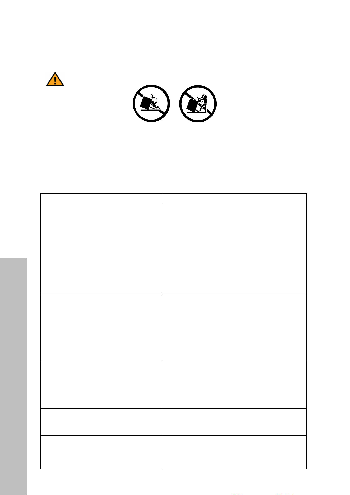
TIPPING DANGER
SECURED WITH A PROPERLY INSTALLED ANTI-TIP DEVICE.
THE DEATH OF A CHILD OR ADULT.
or wall then slide range back so rear range foot is under anti-tip bracket.
the wall. If it tips forward more than 4 inches, the anti-tip device has not been installed correctly.
by the anti-tip bracket.
much force or weight is applied to the open door.
Do not operate the range without the anti-tip bracket in place.
Before removing label, ensure anti-tip bracket is properly installed.
• TIPPING RANGES CAN CAUSE SERIOUS PERSONAL INJURY OR DEATH.
• TO REDUCE THE RISK OF TIPPING OF THE RANGE, THE RANGE MUST BE SECURED
WITH A PROPERLY INSTALLED ANTI-TIP DEVICE.
• FAILURE TO PROPERLY INSTALL THE ANTI-TIP DEVICE INTO THE WALL COULD
RESULT IN THE DEATH OF A CHILD OR ADULT.
ENGLISH FRANÇAIS
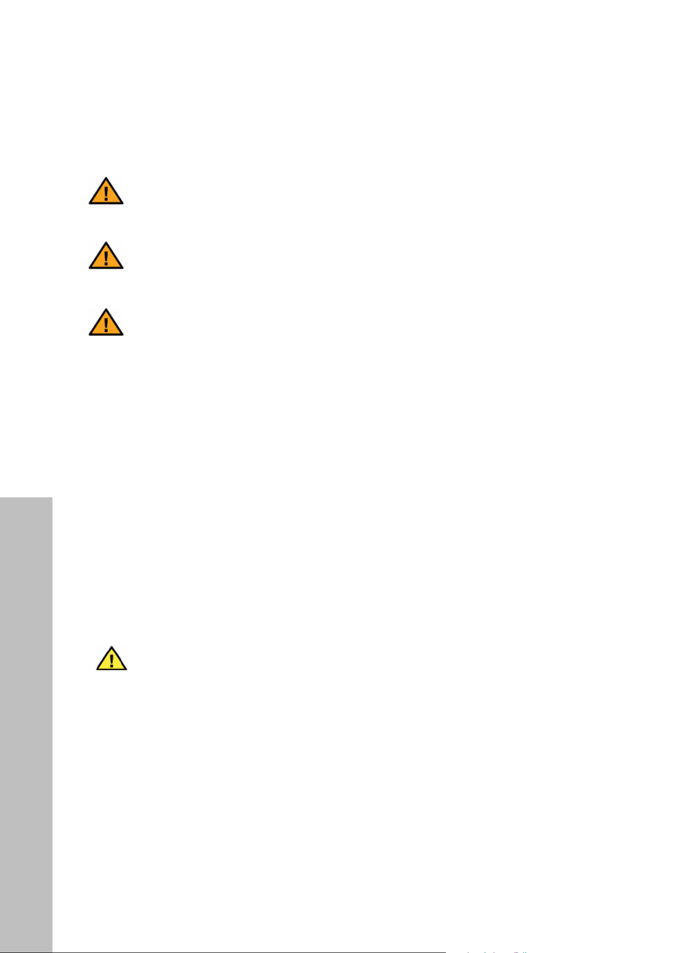
Install the anti-tip device to the structure
and/or the range. Verify the anti-tip
device has been properly installed and
engaged by sliding the range back
toward the wall where both brackets
have been secured, as outlined in the
directions on “Installing The Anti-Tip
Device” on page 42.
Installez le dispositif anti-basculement sur la
structure et/ou la cuisinière. Vérifiez que le
dispositif anti-basculement a été correctement
installé et engagé en faisant glisser la cuisinière
vers le mur où les deux supports ont été fixés,
comme indiqué dans les instructions de «
Installation du dispositif anti-basculement »
à la page 42.
Engage the range to the anti-tip device
by safely tilting the front of the range
upward slightly and moving it back to
its final resting place, making sure the
mounting pins slide under both brackets.
Engagez la cuisinière dans le dispositif anti-
basculement en inclinant légèrement l’avant de
la cuisinière vers le haut et en la ramenant à son
emplacement de repos final, en vous assurant
que les broches de montage glissent sous les
deux supports.
Re-engage the anti-tip device if the
range is moved. Do not operate the
range without the anti-tip device in
place and engaged.
Engager de nouveau le dispositif
antibasculement si la cuisinière est déplacée.
Ne pas utiliser la cuisinière lorsque le dispositif
antibasculement n’est pas installé et engagé.
See installation instructions for details.
Voir les directives d’installation pour obtenir de
plus amples renseignements
Failure to do so can result in death or
serious burns to children or adults.
Toute omission de le faire expose les enfants
et les adultes à un risque de décès ou de
brûlures graves.
Tipping Safety

12
Tipping Safety
IMPORTANT SAFETY INFORMATION
• Ensure the anti-tip device is re-engaged when the range is moved by following the same
steps outlined above and on page 42.
• Carefully pull on the range from the rear. If the brackets are installed correctly, the range
will not tip more than 4" (102 mm) from the wall. If it tips forward more than
4" (102 mm), the anti-tip device has not been installed correctly.
DANGER
DO NOT TIP THE RANGE MORE THAN 4” (102 MM) FROM THE WALL AS IT
COULD TIP OVER AND CAUSE INJURY.
• Never completely remove the leveling legs or the range may not be secured to the anti-
tip device properly. NEVER step or sit on the door.
• The range will not tip during normal use. However, without a properly fastened anti-tip
bracket, the range can tip if too much force or weight is applied to the open door.

13
Ventilation Safety
IMPORTANT SAFETY INFORMATION
VENTILATION SAFETY
WARNING
• The appliance should have proper ventilation in order to keep the unit operating
properly and maintain the temperature of immediate surroundings. Do not obstruct flow
of combustion and ventilation air.
• Observe all governing codes and ordinances, and check your local building codes as
they may vary from the general rules outlined in this manual.
• It is the installer’s responsibility to comply with installation clearances specified on the
model/serial rating plate, in addition to within this Installation Manual.
• For proper operation of a gas appliance, the air necessary for gas combustion must
be able to flow into the room naturally. The air must flow into the room directly through
openings in the outside walls.
• These openings must be constructed so that it will not be obstructed from inside or outside,
and not be constructed close to the floor. The opening is recommended to be on the side
opposite to that on which the flue gases are discharged.
• The appliance should be located for convenient use in the kitchen; recessed installations
must provide complete enclosure of the sides and rear of the range.
• To eliminate risk of burns or fire by reaching overheated surface units, cabinet storage
space located above the range should be avoided. This risk can be further reduced by
installing a range hood or microwave hood combination that projects horizontally a
minimum of 5" (127 mm) beyond the bottom of the cabinets.
• If a range hood is installed with appropriate ducting, maintain a 30" (762 mm) minimum
clearance between the cooking surface and bottom of the hood.
• Avoid placing cabinetry directly above the appliance when possible. If cabinetry is used
above the cooking surface, use cabinets no more than 13" (330 mm) deep.
• Contact a service technician and/or a qualified floor covering installer to check that
wall coverings, countertops, and cabinets located around the appliance can withstand
at least 200 °F (93 °C).
14
IMPORTANT SAFETY INFORMATION
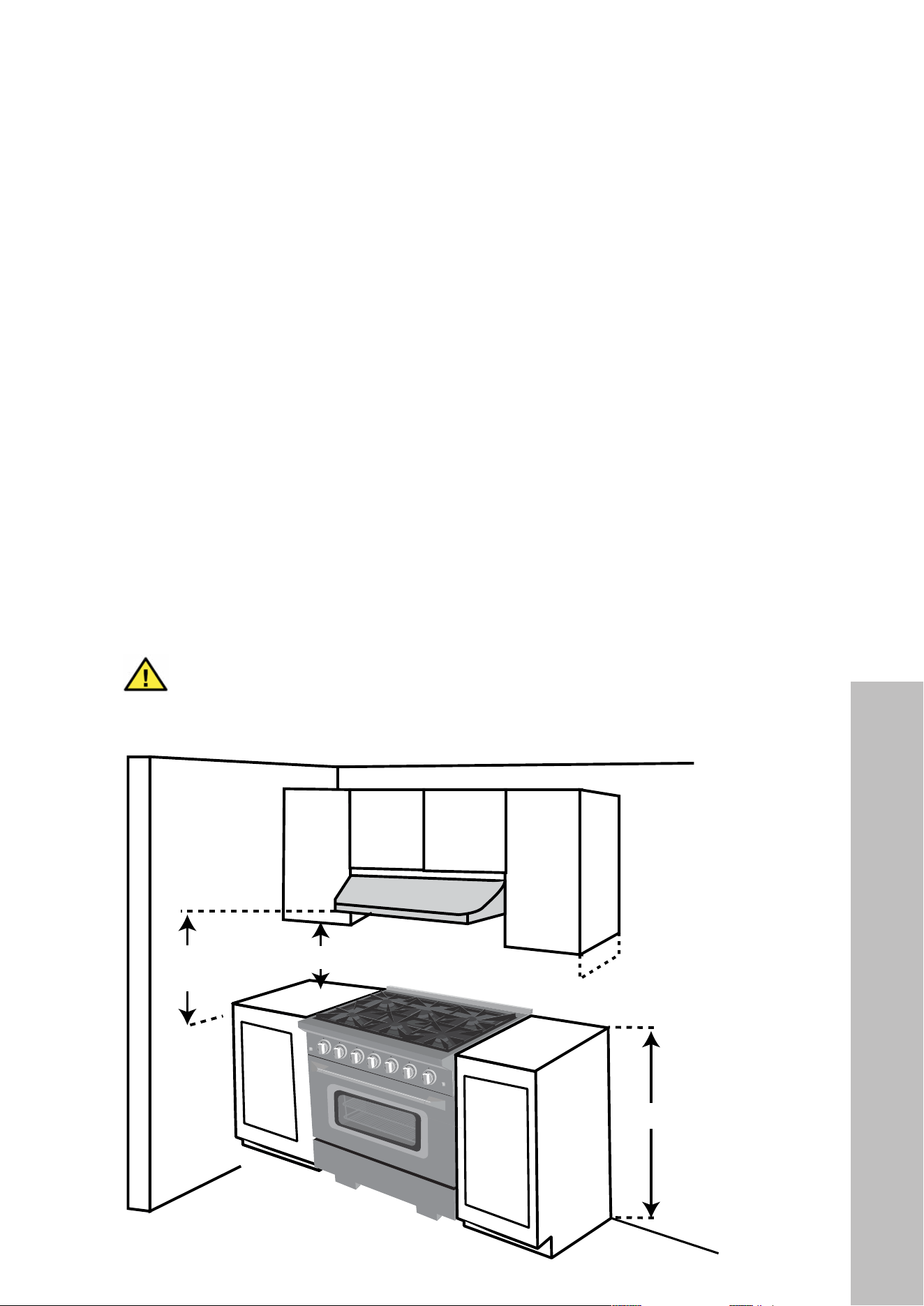
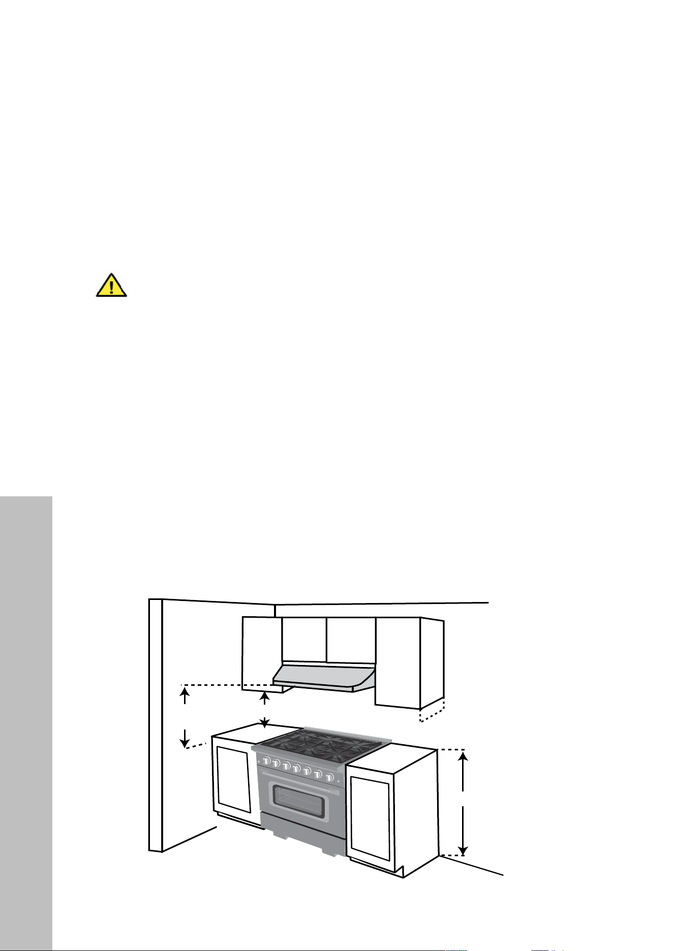
RANGE PLACEMENT
• The dimensions shown below must be used. Given dimensions are minimum clearances
from combustible surfaces. For additional cabinet cut-out details, see page 21.
• Working areas adjacent to the appliance should have 18" (457 mm) minimum clearance
between countertop and cabinet bottom (see image below).
• All openings in the wall or floor where appliance will be installed must be sealed.
• The floor anti-tip device must be installed. To install the anti-tip device shipped with the
range, see “Installing The Anti-Tip Device 1” on page 42.
• A grounded electrical supply is required. See “Connect to Power” section on page
43, as well as additional electrical safety precautions on page 19.
• Proper gas supply connection must be available. See “Gas Connection” section on
pages 28–30, as well as additional safety precautions on page 17.
• NOTE: The diagram below is of an SGR36 series range; minimum clearances are the
same for SGR30 and SGR48 series models.
WARNING
It is the responsibility of the installer to ensure the appliance is properly adjusted
at the time of installation. Situations caused by improper adjustments or improper
installation are not covered under warranty.
— 17 —
STEP 4
Gas Connection
Range Tops:
This range top is designed to operate at a pressure of 4”
of water column on natural gas or 10” of water column on
propane gas (LPG).
This range top can be converted for use on Liquid propane
gas (LPG). When using this range top on LPG gas,
attempting to operate the range top on that gas.
For correct operation, the pressure of natural gas supplied to
the regulator should be between 4” and 5” of water column.
For LP gas, the pressure supplied must be between 10” and
12” of water column.
When checking for correct operation of the regulator, the
inlet pressure must be at least 1” more than the operating
manifold pressure as given above.
Ranges:
For NG, input pressure is 7” W.C. and output pressure 5”
W.C.
For LP, input pressure is 11” W.C. and output pressure: 10”
W.C.
Appliance regulator is set at 5.0” W.C. outlet pressure.
The gas supply pressure for checking the regulator setting is
connector to the regulator on the range. Position range to
permit connection at the shut off valve.
DANGER:
The gas supply line must be equipped with an approved manual shut-off valve. The shut-off valve must be in an easily
accessible location in the same room as the appliance. Do not block access to the shut-off valve. Be sure you know
how and where to shut off the gas supply to the range.
STEP 3B (ranges only)
Dimensions and Clearances
Before installing the range, you must locate and secure
the included anti-tip bracket to the wall for your range.
may install a non-combustible material on the rear
wall above the range and up to the vent hood. It is not
necessary to install non-combustible materials behind
the range below the countertop height.
The minimum distance from the side of the range above
the countertop to combustible sidewalls must be at
least 10 inches.
Installation
30" (762 mm) Min.
18
"
(457 mm) Min.
13
"
(330 mm) Max.
36
"
(914 mm)
Figure 6
Appliance Placement

15
IMPORTANT SAFETY INFORMATION
GAS SAFETY
DANGER
Explosion hazard conditions will exist unless you perform ALL of the following;
failure to do so can result in death, explosion, or fire.
• Use a new CSA International approved gas supply line.
• Install a manual gas shut-off valve.
• Securely tighten all gas connections.
• If connected to liquid propane, have a qualified person make sure gas pressure does not
exceed 3.2 kPa/13" W.C.P.
• Examples of a qualified person include:
• Licensed heating personnel
• Authorized gas company personnel
• Authorized service personnel
• Observe all governing codes and ordinances:
• IMPORTANT: This installation must conform with all local codes and ordinances. In the
absence of local codes, installation must conform with American National Standard,
National Fuel Gas Code ANSI Z223.1/NFPA 54—latest edition, or CAN/CGA
B149—latest edition.
• In Canada, installation must conform to the current natural gas installation code,
CAN 1-1.1-M81, and with local codes where applicable. This appliance has been
design-certified according to ANSI Z21.1b-201 latest edition. A statement of the
maximum gas supply pressure in accordance with the inlet pressure rating of the gas
appliance pressure regulator is supplied.
• IMPORTANT: Leak testing of the appliance must be conducted according to the
manufacturer’s instructions.
• The appliance should be connected to the supply line with a 1/2" metal gas line or a
certified flexible type stove connector. To prevent gas leaks, put an approved sealing
compound that is resistant to liquefied petroleum gases on all threaded connections.
Gas Safety
16
BEFORE INSTALLATION
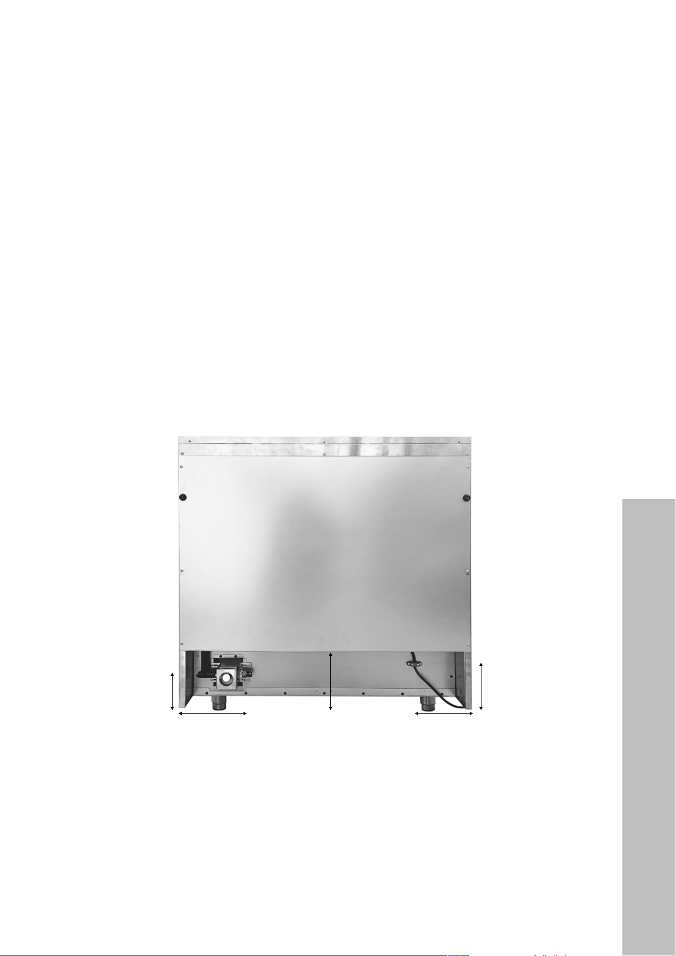
GAS SUPPLY AND ELECTRICAL CONNECTION
• The gas supply should be within convenient distance for proper connection to the gas
regulator, which is located within the oven’s recess at bottom left (as outlined below with
an SGR36 series range).
• Also noted below is the location of the power cord (54" – 1372 mm) when planning for
where to locate the dedicated power circuit.
• Height measurements below are based on legs being at their lowest position
(2 3/4" – 70 mm). Legs can be extended up to 4 1/4" (108 mm) tall depending on
kitchen layout.
• NOTE: While the image below is of an SGR36 series range, measurements are similar on
both the SGR30 and SGR48 series ranges, though they may vary slightly. Professional
installers should carefully take these dimensions into account when hooking the unit up
to its electrical and gas supplies.
7 1/2" (191 mm):
Width from edge of range
to gas regulator fitting
6 1/2" (165 mm):
Width from edge
of range to center
of power cord
10 1/4" (260 mm):
Height from bottom of oven
recess to bottom of range legs
5 3/4" (146 mm):
Height from gas
regulator connection to
bottom of range legs
7 1/4" (184 mm):
Height from center of power
cord to bottom of range legs
Gas Supply

17
BEFORE INSTALLATION
WARNING
The range may not sit flush to the back wall if the gas or electrical connections
are installed outside of these dimensions.
NATURAL GAS:
• This appliance is designed for use with natural gas or, after proper conversion, for use
with liquid propane gas.
• This appliance is factory set for use with natural gas. The model/serial rating plate has
information on the types of gas that can be used.
LIQUID PROPANE GAS:
• Conversions must be done by a qualified service technician. Go to page 31 for liquid
propane conversion instructions.
• Do not attempt to convert the appliance from the gas specified on the model/serial
rating plate for use with a different gas without consulting the local gas company.
Gas Supply

18
BEFORE INSTALLATION
GAS CONNECTIONS
• IMPORTANT: Do not apply pressure directly to the appliance manifold pipe when
tightening supply connections. The manifold pipe should be held securely at the pressure
regulator to prevent twisting. Hold the pressure regulator with a wrench during tightening,
or the manifold pipe may be twisted and split and cause a dangerous leak.
• NOTE: Check all piping connections in the unit for leaks. Use a soap solution, 75%
water, 25% dish soap. It is possible for connections made at the factory to leak, due to
vibration encountered in shipping. Make certain you have checked them all, and repair
any connections that leak.
DANGER
NEVER use an open flame to check for gas leaks.
• The appliance and its individual shut-off valve must be disconnected from the gas supply
piping system during any pressure testing of that system at test pressures in excess of 1/2
psig (0.12 kPa).
• The appliance must be isolated from the gas supply piping system by closing its individual
manual shut-off valve during any pressure testing of the gas supply piping system at test
pressures equal to or less than 1/2 psig (0.12 kPa).
GAS LINE SHUT-OFF VALVE
• To reduce the possibility of gas leaks, apply Teflon tape or a thread compound approved
for use with liquid propane or natural gases to all threaded connections.
• Install an agency-approved, properly-sized manual gas line shut-off valve in the gas
line in an easily accessed location outside the range in the gas piping external to the
appliance for the purpose of turning on or shutting off gas to the appliance.
• This valve is not shipped with the appliance and must be provided by the installer.
• Install a male 1/2" flare union adapter (SGR30 and SGR36 series ranges) or 3/4"
flare union adapter (SGR48 series ranges) to 1/2" or 3/4" NPT internal thread elbow
at the inlet of the regulator. Use a wrench on the regulator fitting to avoid damage.
• Install a male 1/2" or 3/4" flare union adapter to the NPT internal thread of the manual
shut-off valve, taking care to secure the shut-off valve to keep it from turning.
Gas Supply

19
BEFORE INSTALLATION
ELECTRICAL SAFETY
DANGER
ELECTRIC SHOCK HAZARD
• Failure to follow these instructions can result in death, fire, or electrical shock.
• Any additions, changes, or conversions required to properly operate this appliance
must be made by a qualified service technician in accordance with the manufacturer’s
instructions and all codes and requirements of the local governing authority.
• Failure to follow the instructions could result in serious injury or property damage. The
qualified agency performing this work assumes responsibility for the conversion.
• DO NOT operate this appliance using a 2-prong adapter. DO NOT use an extension
cord. If a 2-prong wall receptacle is the only available outlet, it is the responsibility of
the consumer to have it replaced with a properly grounded 3-prong wall receptacle
installed by a qualified electrician.
• Severe shock or damage to the range may occur if the appliance is not installed by a
qualified installer or electrician.
• This appliance is 120VAC/60Hz. A dedicated circuit, protected by a minimum 15-amp
circuit breaker, is required for electrical connection.
• Total input power is 23.4 kW for SGR30 series ranges, 30.2 kW for SGR36 series
ranges, and 41.1 kW for SGR48 ranges, each with a 5 amp capacity.
• For personal safety, the appliance must be properly grounded.
• The power supply must be the correct polarity. Reverse polarity will result in continuous
sparking of the electrodes, even after flame ignition. If you have any doubt whether the
power supply has the correct polarity or is properly grounded, have it checked by a
qualified electrician.
WARNING
Ranges are equipped with a 3-prong NEMA 5-15P plug for your protection
against shock hazard and should be plugged directly into a properly grounded
receptacle. Do not cut or remove the prong from this plug.
CAUTION
Label all wires prior to disconnection when servicing controls. Wiring errors
can cause improper and dangerous operation. Verify proper operation
after servicing.
Electrical Supply

20
BEFORE INSTALLATION
TOOLS NEEDED (INCLUDED)
• Allen wrench / hex key (for handle installation)
TOOLS AND ADDITIONAL PARTS NEEDED (NOT INCLUDED)
• Tape measure
• Phillips-head screwdriver
• Flat blade screwdriver
• 1/8" (3 mm) flat blade screwdriver
• Hex screwdriver
• Level
• Hand or electric drill
• Wrench or pliers
• Pipe wrench
• 15/16" (24 mm) combination wrench
• 1/8" (3 mm) drill bit (for wood)
• Marker or pencil
• Pipe-joint compound resistant to LP gas
• Noncorrosive leak-detection solution
• 7 mm socket wrench or nut driver
• 10 mm socket wrench or nut driver
• Manual gas line shut-off valve
• Male 1/2" or 3/4" flare union adapter
• 1/2" or 3/4" NPT internal thread elbow
Scan to follow along with a video to review how to assemble your range.
NOTE: The range in the video is of an SGR36 series range; check your
range cover to see which elements apply to your range.
ADDITIONAL PARTS
• Check local codes, consult your gas supplier, and check the existing gas/electrical
supply prior to beginning the installation process.
• See the “Electrical Connection” and “Gas Connection” sections of this manual for
further information and guidance on the additional parts a qualified installer will need
to perform this installation.
Tools Needed
21
BEFORE INSTALLATION
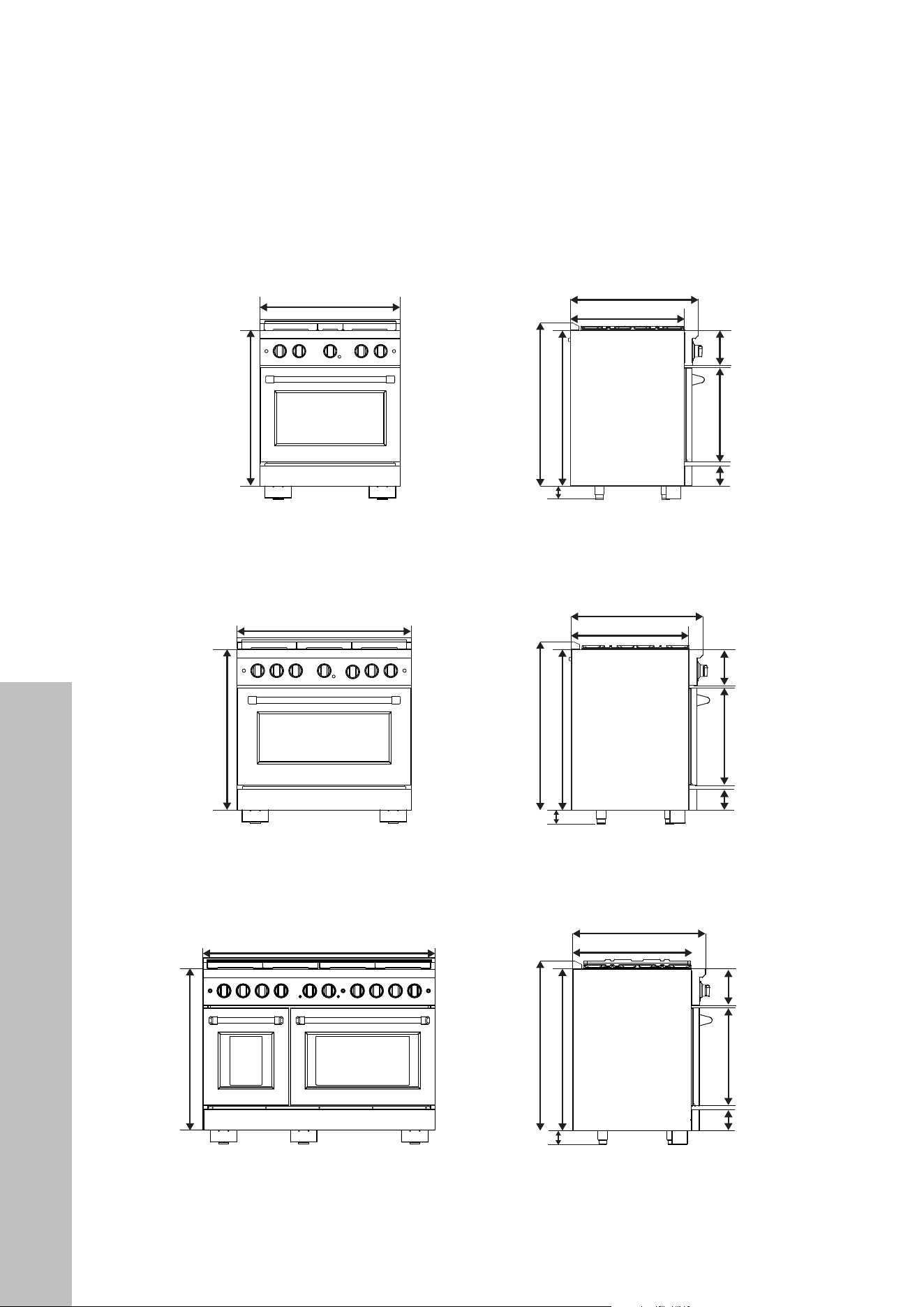
PRODUCT SPECIFICATIONS
47 7/8" (1216 mm)
7 1/2" (190 mm)
20 1/8" (511 mm)
4 5/16" (110 mm)
7 1/2" (190 mm)
20 1/8" (511 mm)
4 5/16" (110 mm)
7 1/2" (190 mm)
20 1/8" (511 mm)
4 5/16" (110 mm)
36" (915 mm)
30" (763 mm)
33 1/4" (844 mm)
33 1/4" (844 mm)
35 5/8" (905 mm)
33 1/4" (884 mm)
35 5/8" (905 mm)
33 1/4" (884 mm)
27 5/16" (694 mm)
24 3/8" (619 mm)
27 5/16" (694 mm)
24 3/8" (619 mm)
27 5/16" (694 mm)
24 3/8" (619 mm)
2 3/4" (70 mm)
to 4 1/4" (108 mm)
2 3/4" (70 mm)
to 4 1/4" (108 mm)
2 3/4" (70 mm)
to 4 1/4" (108 mm)
33 1/4" (844 mm)
SGR48 SERIES RANGES
SGR36 SERIES RANGES
SGR30 SERIES RANGES
35 5/8" (905 mm)
33 1/4" (884 mm)
Product Specifications

22
Installation Specifications
BEFORE INSTALLATION
RECOMMENDED CABINET CUT-OUT DIMENSIONS
• SGR30 Series Ranges: 30 1/4" W x 24 3/4" D x 36" H
768 mm W x 629 mm D x 914 mm H
• SGR36 Series Ranges: 36 1/4" W x 24 3/4" D x 36" H
921 mm W x 629 mm D x 914 mm H
• SGR48 Series Ranges: 48 1/8" W x 24 3/4" D x 36" H
1222 mm W x 629 mm D x 914 mm H
NOTES:
• Width: Recommended cut-outs allow for 1/8" (3 mm) of space on each side; your
kitchen layout may vary slightly, so plan accordingly.
• Depth: This is recommended beyond the standard cabinet depth of 24" (610 mm) so the
front face of the oven sticks out from the counter to fully and safely open the door for
optimal use. The additional 3/4" (19 mm) accounts for full depth of the range as well as
the rubber bumpers on the back so the range may be pushed flush to the wall.
• Height: This is recommended based on standard cabinet heights of 36" (914 mm).
Please note: 36" (914 mm) is based on the legs being at their lowest level; the legs can
be adjusted by roughly 1 1/2" (38 mm) depending on your preferred height. Again,
kitchen layouts vary.
WARNING
The use of cabinets for storage above the appliance may result in a potential fire
hazard. Combustible items may ignite; metallic items may become hot and cause
burns. If cabinet storage is necessary, the risk can be reduced by installing a
range hood that projects horizontally a minimum of 5" (127 mm) beyond the
bottom of the cabinets.
23
Installation Specifications
BEFORE INSTALLATION
PRE-INSTALLATION SPECIFICATIONS AND INSTRUCTIONS
• If a range hood is installed above the range, the clearance of the hood should be
installed between 30" to 36" (762 mm to 914 mm) above the top surface of the range.
• The range should only be used with ducted range hoods.
• Do not install with a downdraft ventilation system.
WARNING
Items of interest to children should not be placed in cabinets above the
range. Children climbing on the range to reach items could be seriously
injured or burned.
• Before installing the range, you must locate and secure the included anti-tip device to the
wall for your range. To install the anti-tip device shipped with the range, see “Installing
The Anti-Tip Device” section on page 42.
• The range may be installed flush to the rear wall. You may install a non-combustible
material on the rear wall above the range and up to the range hood. It is not necessary
to install non-combustible materials behind the range below the countertop height.
• The minimum distance from the side of the range above the countertop to combustible
sidewalls and cabinets must be at least 10" (254 mm).
• NOTE: The diagram below is of an SGR36 series range; minimum clearances are the
same for SGR30 and SGR48 series models.
— 17 —
STEP 4
Gas Connection
Range Tops:
This range top is designed to operate at a pressure of 4”
of water column on natural gas or 10” of water column on
propane gas (LPG).
This range top can be converted for use on Liquid propane
gas (LPG). When using this range top on LPG gas,
attempting to operate the range top on that gas.
For correct operation, the pressure of natural gas supplied to
the regulator should be between 4” and 5” of water column.
For LP gas, the pressure supplied must be between 10” and
12” of water column.
When checking for correct operation of the regulator, the
inlet pressure must be at least 1” more than the operating
manifold pressure as given above.
Ranges:
For NG, input pressure is 7” W.C. and output pressure 5”
W.C.
For LP, input pressure is 11” W.C. and output pressure: 10”
W.C.
Appliance regulator is set at 5.0” W.C. outlet pressure.
The gas supply pressure for checking the regulator setting is
connector to the regulator on the range. Position range to
permit connection at the shut off valve.
DANGER:
The gas supply line must be equipped with an approved manual shut-off valve. The shut-off valve must be in an easily
accessible location in the same room as the appliance. Do not block access to the shut-off valve. Be sure you know
how and where to shut off the gas supply to the range.
STEP 3B (ranges only)
Dimensions and Clearances
Before installing the range, you must locate and secure
the included anti-tip bracket to the wall for your range.
may install a non-combustible material on the rear
wall above the range and up to the vent hood. It is not
necessary to install non-combustible materials behind
the range below the countertop height.
The minimum distance from the side of the range above
the countertop to combustible sidewalls must be at
least 10 inches.
Installation
30" (762 mm) Min.
18
"
(457 mm) Min.
13
"
(330 mm) Max.
36
"
(914 mm)
Figure 6
24
ADDITIONAL PRE-INSTALLATION STEPS
• Before beginning installation, please carefully read and follow the important safety
precautions on pages 1–15.
• Safety instructions pertaining to each step have been outlined in the installation steps;
however it is important to read all the safety instructions.
• It is the installer’s responsibility to comply with installation clearances included in
this manual.
WARNING
Ranges are extremely heavy (200+ lb/91+ kg). Please use proper equipment
and adequate manpower when moving the range to avoid personal injury, as
well as damage to the unit, floor, and cabinets. Please note the range rests on
adjustable steel legs; use care when moving the range to not break the legs.
Failure to follow this advice may result in damage or personal injury.
• Plan a desirable location that fits all requirements in the Safety and Installation sections
of this manual.
• Unpack the appliance and parts carefully (burners, burner caps, cooking grates, etc.).
Make sure all parts are included as shown on page 20 and set aside.
• Assemble all tools as shown on “BEFORE INSTALLATION” on page 20. DO NOT
remove the protective film covering the appliance until it is fully installed; this avoids
accidental scratching or damage of the stainless steel, glass, and porcelain cooktop.
WARNING
Do not lift the unit by the oven door handle. Doing so increase risk of personal
injury and may damage the range, its door, or the door handle, and as such
may void the product warranty.
BEFORE INSTALLATION
Installation Preparation
25
INSTALLATION
Installing Parts
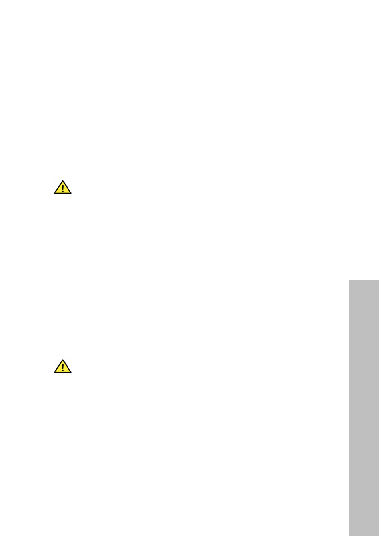
BURNER SPREADS AND CAPS
• After unpacking the range, set the cast iron grates aside and remove the burner spreads
and caps from the parts storage location under the grates.
• Place each spread on the appropriate burner by making sure the hole fits over the white
metal electrode spark tip. Next, place each burner cap on top until snug.
• Burners may only partially ignite or not light at all if burner spreads (B) or caps (A) are
not properly installed, as outlined below:
A
B
A
B
Correct
Incorrect
Correct Incorrect
A
B
CAST IRON GRATES
• Next, place the cast iron grates on top the range, using care to not scratch the porcelain
cooktop. There are rubber feet on the bottom of each grate and slots on the cooktop
where each grate fits into.
• The SGR48 series range comes with a reversible cast iron griddle that can be placed
vertically (front to back) on any of the four cast iron grates. Do not place the griddle
horizontally (left to right) across multiple grates.
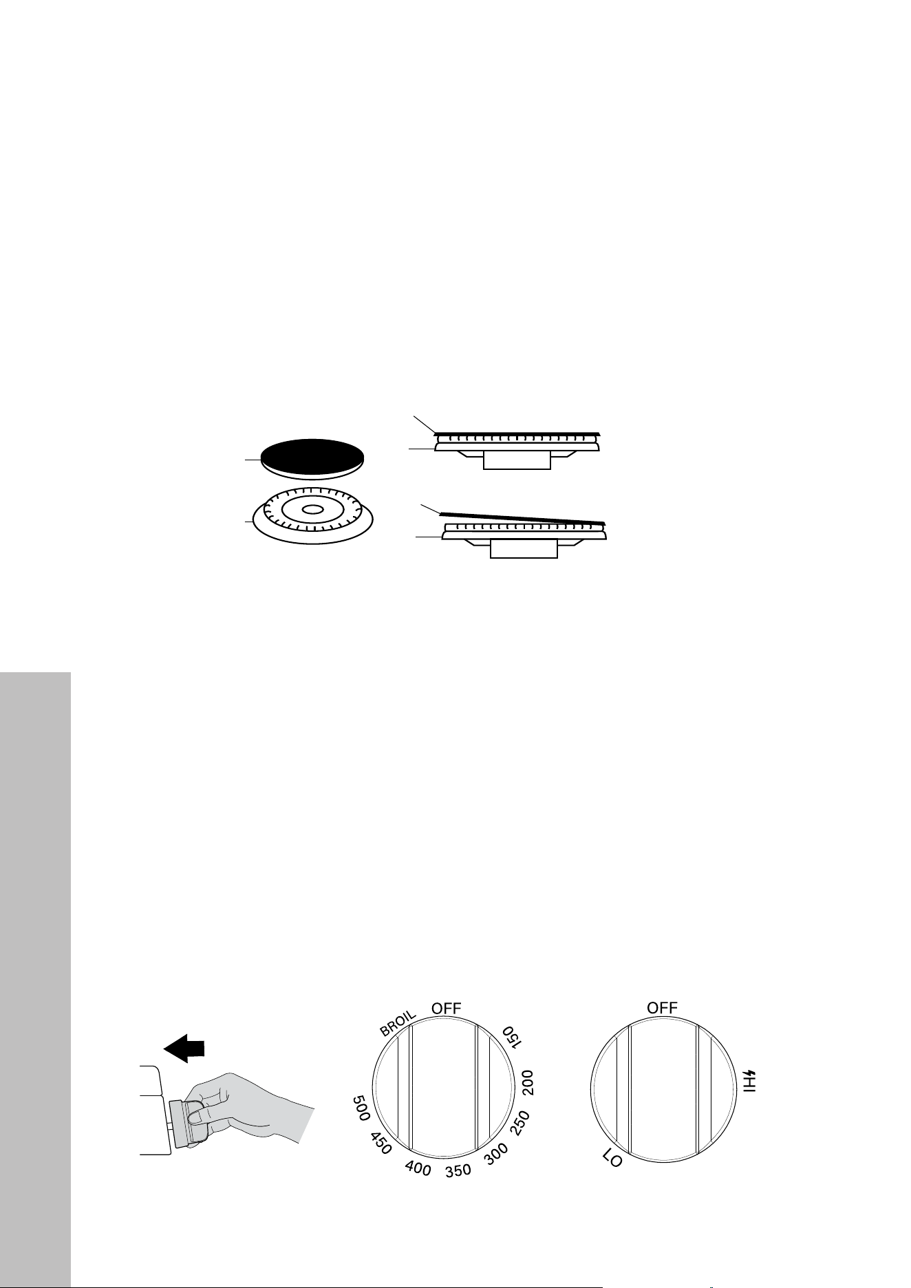
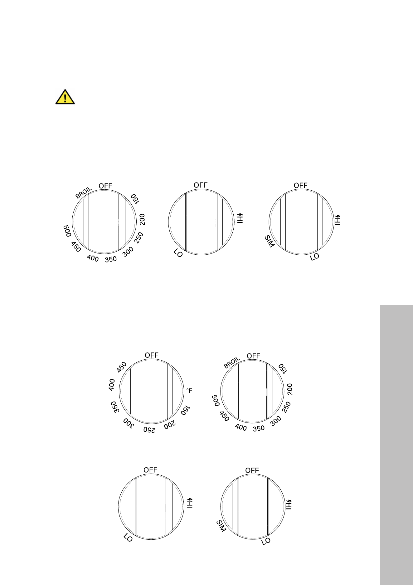
KNOBS FOR SGR30 SERIES RANGES (5 TOTAL)
• To install knobs, hold each in the “OFF” position and carefully push them straight onto
the single valves protruding from the front of the cooktop until snug.
• For the SGR30 series range, the oven control knob goes on the middle single valve, with
the individual burner knobs on each side, as outlined below:
— 27 —
Operation
setting (SIM) for gentle simmering (620 BTU/hr). Use the
SIM setting for melting chocolate and butter, cooking rice
and delicate sauces, simmering soups and stews, and
keeping cooked food hot.
Never leave the appliance unattended when in use.
Boil over causes smoking and greasy spills that may
ignite.
its sides. This could discolor and damage the utensil and
you may get burned touching a hot handle.
burner that is on.
quickly, particularly on a high setting.
Incorrectly or incompletely assembled burners may
over, make sure you clean the affected burners before
using them again. Food residue may clog the igniter and
instructions.
advice.
Guidelines for Using Cooktop Burners
Surface Burner Ignition
u
To light the top burners, push the appropriate
control knob to release gas.
v position. You will hear a clicking noise, the sound of
the electric spark igniting the burner.
w
Once bur ner ignition has been achieved, then turn
the burner control knob to adjust the desired heat
setting.
NOTE: When one burner is turned to the “Hi” position, all
the burners will spark. Do not attempt to disassemble or
clean around any burner while another burner is on. Do
not touch any burner cap, burner base, or igniter while
the igniters are sparking.
Heat Settings
HI Ignites the burners.
Simmer
Melting small quantities, steaming rice, warming food,
melting chocolate or butter.
Low Melting large quantities.
Low – Medium
Low-temperature frying, simmering large quantities, heating
milk, cream sauces, gravies.
Medium
Sautéing and browning, braising, pan-frying, maintaining
slow boil on large quantities.
Medium – Hi
High-temperature frying, pan boiling, maintaining slow boil
on large quantities.
Hi Boiling liquid quickly, deep frying.
Oven Knob (1) Burner Knobs (4)
26
WARNING
The SGR36 series range comes with 1 brass dual function burner, and the
SGR48 series range includes 2 brass dual function burners. The burner knobs
for those include a “SIM” setting, as outlined in the images below.
KNOBS FOR SGR36 SERIES RANGES (7 TOTAL)
The oven knob goes on the middle single valve, with individual burner knobs going on each
side. The dual function knob goes on the far right side of the range.
Oven Knob (1) Burner Knobs (5) Dual Function Knob (1)
KNOBS FOR SGR48 SERIES RANGES (10 TOTAL)
The oven knobs go on the 2 middle single valves, with the small oven knob on the left.
Individual burner knobs go on each side. One dual function knob goes immediately left of
the small oven burner, and the other goes on the far right side of the range.
Small Oven Knob (1)
Burner Knobs (6) Dual Function Knobs (2)
Large Oven Knob (1)
Installing Parts
INSTALLATION
27
Installation Parts
INSTALLATION
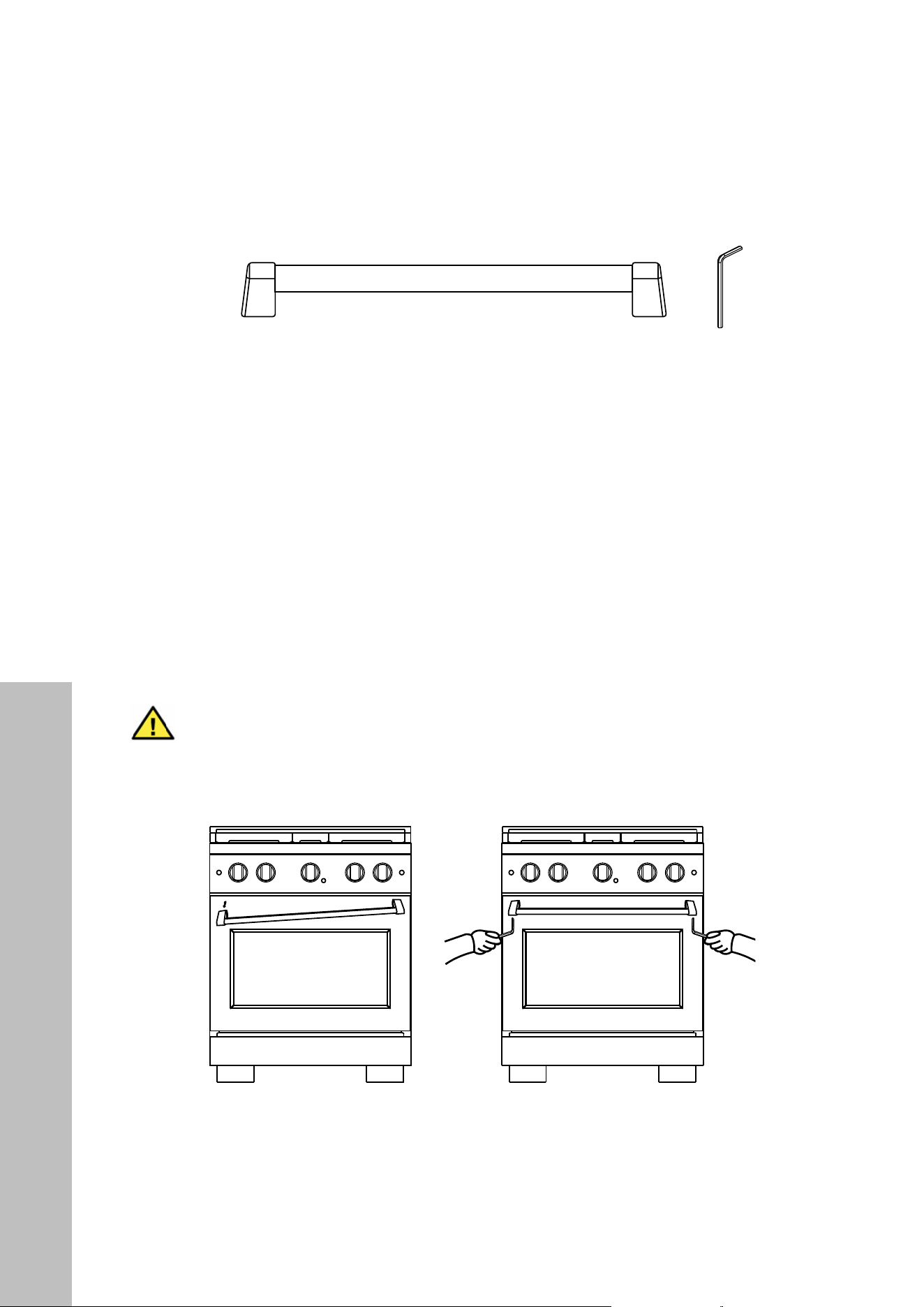
INSTALLING THE HANDLE
• To install the handle on the oven door, place each handle bracket onto the pre-installed
mounting studs located at both sides of the oven door, as outlined below in the left
image below.
• Once the handle is secured, locate the screw holes on the underside of each handle
bracket base. Using the provided 7/64" (3 mm) Allen wrench / hex key, tighten the left
and right screws until the handle is firmly in place, as outlined below in the right image.
• The handle should be perfectly level if installed correctly.
• NOTE: The diagrams on this page reference the SGR30 series range; the handle
installation method is the same for the SGR36 model. Handles will come pre-installed
on the SGR48 series range.
WARNING
Use care to not overtighten, or you risk stripping the screws and then your
handle may be unstable or fall off, increasing the risk of injury or burns.

28
INSTALLATION
GAS CONNECTION
• While ranges come factory ready to operate on natural gas (NG), the appliance can be
converted for use on liquid propane gas (LPG). When using this range on liquid propane
gas, the conversion must be made by a qualified installer before attempting to operate
the range top on that gas.
• For NG, the input pressure is 1.7 kPa/7" W.C.P. and the output pressure
1.2 kPa/5" W.C.P.
• For LP, input pressure is 2.7 kPa/11" W.C.P. and output pressure is 2.5 kPa/10" W.C.P.
• The appliance regulator is set at 1.2 kPa/5" W.C.P. output pressure.
• The gas supply pressure for checking the regulator setting is 1.2 kPa/5" W.C.P. (NG)
and 2.5 kPa/10" W.C.P. (LPG).
• All gas connections must comply with national and local codes. When connecting a
flexible gas line connector to the regulator on the range, be sure to position the range to
permit connection at the manual shut off valve.
DANGER
The gas supply line must be equipped with an approved manual shut-off valve.
The shut-off valve must be in an easily accessible location in the same room as
the appliance. Do not block access to the shut-off valve. Be sure you know how and
where to shut off the gas supply to the range.
IMPORTANT:
• The pressure regulator located at the inlet of the appliance manifold must remain in the
supply line regardless if natural gas or liquid propane gas is being used.
• The gas regulator has a clear plastic shield covering the inlet to protect against debris.
Be certain this has been removed prior to connecting the supply line or coupler.
• A flexible metal appliance connector to connect the range to the gas supply should be
a maximum of 3' (914 mm) in length for easy installation.
• In Canada, flexible connectors should be single-wall metal connectors less than
6' (1829 mm) in length.
Gas Connection

29
INSTALLATION
GAS CONNECTION (CONTINUED)
WARNING
EXPLOSION HAZARDS
• Please read ALL safety precautions on pages 1–15 before beginning installation.
• Only use a CSA-approved gas supply line.
• You must install an approved manual shut-off valve.
• Securely tighten all gas connections.
• If connected to LPG, have a qualified person make sure gas pressure does not exceed
2.7 kPa/11" W.C.P. Examples of a qualified person include licensed heating personnel,
authorized gas company personnel, and authorized service personnel.
• Failure to follow these warnings can result in death, explosion, or fire.
GAS INSTALLATION STEPS
1. Shut off the main gas supply valve before removing the old cooking appliance (if
applicable) and leave it off until the new hook-up has been completed. Don’t forget to
relight the pilots on other gas appliances when you turn the gas back on.
2. Because hard piping restricts movement of the appliance, the use of a CSA-certified
flexible metal appliance connector is recommended unless local codes require a hard-
piped connection. Never reuse an old connector when installing a new appliance. If the
hard piping method is used, you must carefully align the pipe. To prevent gas leaks, use
pipe joint compound resistant to NG gases on all male external pipe threads.
3. Use a flexible gas line to connect to the 1/2" regulator fitting, located on the bottom left
corner underneath the appliance (when facing the rear of the range).
4. When all connections have been made, be sure all appliance controls are in the off
position and turn on the main gas supply valve. Check for gas leaks by using a 75%
water, 25% dish washing soap solution. If a gas leak occurs, shut off gas immediately,
tighten all connections, and retest for leaks.
Gas Connection
30
GAS CONNECTION (CONTINUED)
DANGER
SAFETY AND EXPLOSION HAZARDS
• Please read ALL safety precautions on pages 1–15.
• NEVER use an open flame to check for leaks from gas connections. Checking for leaks
with a flame may result in a fire or explosion.
• Securely tighten all connections if necessary to prevent gas leakage in the appliance or
supply line.
• Check alignment of control knob valves after connecting the appliance to the gas supply
to be sure the appliance manifold pipe has not moved. A misalignment could cause the
valve stems to rub on the control panel, resulting in a gas leak at the valve.
• Disconnect this appliance and its individual manual shut-off valve from the gas supply
piping system during any pressure testing of that system at test pressures in excess of 1/2
psi (13" W.C.P./3.2 kPa).
• Isolate the appliance from the gas supply piping system by closing its individual manual
shut-off valve during any pressure testing of the gas supply piping system at test pressures
equal to or less than 1/2 psi (13" W.C.P./3.2 kPa).
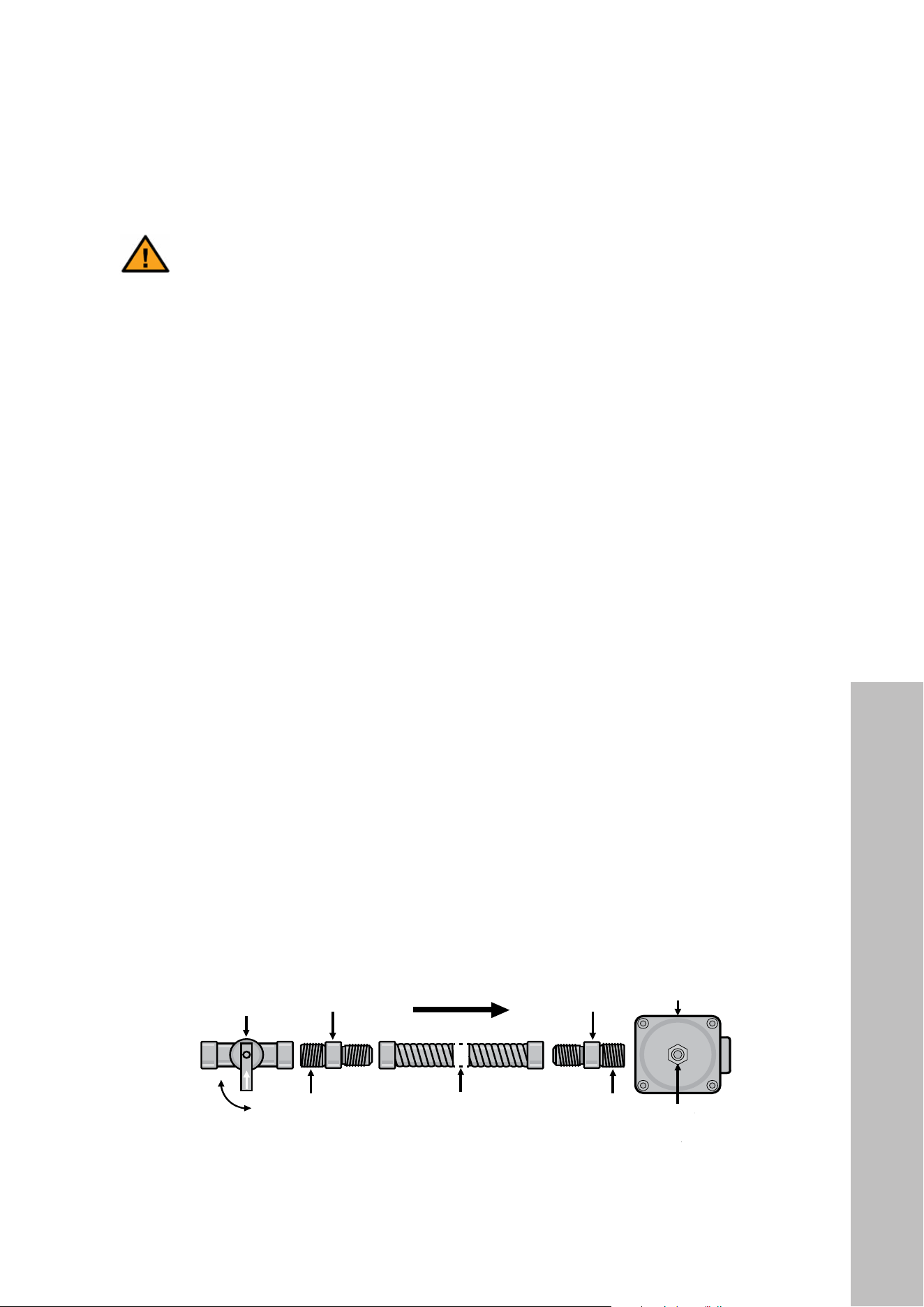
• The below figure demonstrates the proper gas hook-up flow for the SGR30 series ranges
and SGR36 series ranges. The pressure regulator is located at the bottom right corner
when facing the unit (bottom left corner when facing it from behind).
• NOTE: The pressure regulator and cap come pre-installed on the unit; the other parts in
the figure below are not supplied and are the responsibility of the customer to obtain for
a qualified installer to install to ensure a safe and effective gas hook-up.
— 19 —
Installation
STEP 5 (Optional)
(Must be done before Step 6 if converting to Propane)
Gas Conversion
This appliance can be used with Natural Gas or LP/Propane
Gas. It is shipped from the factory for use with Natural Gas. A
kit for converting to LP gas is supplied with your appliance.
u
When the appliance is converted for Liquid Petroleum
(LP) Gas, the LP gas supply is required to provide a
minimum of 10” to a maximum of 12” water column to
the appliance regulator.
Following LP Gas
Conversion, complete
Regulator Pressure”;
Burner Flames”; and
.
Adjusting the Regulator Pressure
v
w
Unscr ew the regulator cap with a wrench (see Figure
9).
Remove r etainer pin by pulling it out (see Figure 10).
Reverse the r etainer pin and snap it back into the
U
Scr ew the regulator cap back into the regulator and
DO NOT over-tighten (see Figures 12 and 13).
WARNINGS:
pages 4 to 10.
Step 4 can result in serious personal injury and
property damage.
The conversion must be performed by a qualified
service technician in accordance with the kit instruc-
tions and all local codes and requirements. Failure
to follow instructions could result in serious injury or
property damage. The qualified agency performing this
work assumes responsibility for the conversion.
Joint Joint
Flexible Connector
Off
On
Manual
Shut off
Valve
Pressure
Regulator
Flare
Union
Flare
Union
Gas Flow
Access
Cap
Figure 9
SGR30 and SGR36 models
SGR48 models
SGR30 and
SGR36 models
SGR48 models
SGR30 and SGR36 models
SGR48 models
SGR30 and SGR36 models
SGR48 models
INSTALLATION
Gas Connection
31
Liquid Propane Conversion
INSTALLATION
LIQUID PROPANE GAS CONVERSION PROCEDURE (OPTIONAL)
CAUTION
CAUTION. The gas supply shall be shut off prior to disconnecting the electrical
power, before proceeding with the conversion.
CAUTION
CAUTION: Before proceeding with the conversion, shut off the gas supply to the
appliance prior to disconnecting the electrical power.
ATTENTION
Attention : Avant de procéder à la conversion, fermer d’abord la source
d’alimentation en gaz de l’appareil, puis débrancher le cordon d’alimentation
en électricité.
IMPORTANT:
• If you plan to convert to propane, this procedure must be completed before installing the
anti-tip device. If you are operating the range on factory-installed natural gas and do
not need to convert to liquid propane, skip ahead to page 42.
• A kit for converting to liquid propane gas is supplied with your appliance. The kit is marked
• SGR30 series ranges: “Liquid Propane Gas (LPG) Orifice Kit for SGR30 Series
(SGP-LPOK30)”
• SGR36 series ranges: ”Liquid Propane Gas (LPG) Orifice Kit for SGR36 Series
(SGP-LPOK36)”
• SGR48 series ranges: ”Liquid Propane Gas (LPG) Orifice Kit for SGR48 Series
(SGP-LPOK48)”
WARNING
IMPORTANT SAFETY MEASURES
• Please make sure to read ALL safety precautions on pages 1–15.
• Failure to make the appropriate conversion after completing the gas connection process
outlined on pages 28–30 may result in serious injury and property damage.
• The conversion must be performed by a qualified service technician in accordance with
the kit instructions and all local codes and requirements.
• Failure to follow instructions could result in serious injury or property damage. The
qualified agency performing this work assumes responsibility for the conversion.
• When the appliance is converted for liquid propane gas, the LPG gas supply is required
to provide a minimum of 2.5 kPa/10" W.C.P. to a maximum of 3.2 kPa/13" W.C.P. to
the appliance regulator.
32
Liquid Propane Conversion
INSTALLATION
LIQUID PROPANE CONVERSION (CONTINUED)
WARNING
WARNING
This conversion kit shall be installed by a qualified service agency in accordance
with the manufacturer’s instructions and all applicable codes and requirements of the
authority having jurisdiction. If the information in these instructions is not followed
exactly, a fire, explosion or production of carbon monoxide may result causing
property damage, personal injury or loss of life. The qualified service agency is
responsible for the proper installation of this kit. The installation is not proper and
complete until the operation of the converted appliance is checked as specified in
the manufacturer’s instructions supplied with the kit.
AVERTISSEMENT
AVERTISSEMENT
Cet ensemble de conversion doit être installé par un organisme de service qualifié,
conformément aux directives du fabricant ainsi qu’à tous les codes applicables
et à toutes les exigences des autorités compétentes. Si les directives ne sont pas
suivies à la lettre, un incendie, une explosion ou une émission de monoxyde de
carbone pourrait se produire et entraîner des dommages matériels et des blessures
graves ou mortelles. L’organisme de service qualifié est responsable de l’installation
appropriée de cet ensemble de conversion. L’installation n’est pas considérée
adéquate et complète tant que le fonctionnement de l’appareil converti n’a pas
été vérifié, conformément aux directives du fabricant fournies avec l’ensemble
de conversion.
33
LIQUID PROPANE CONVERSION (CONTINUED)
Manifold pressure should be checked on the range top by the technician using a manometer
and a ZLINE-provided test point adapter as outlined in below (the figure shows an SGR36
series range; the procedure is the same for all models):
• By hand, remove the burner spread and burner cap from the rear left or front left burner
on the range top.
• Using a 7mm nut driver or wrench, remove the gas orifice from the bottom of the burner
and mount the test point adapter (see figure below).
• Turn the rear left or front left burner control knob to the “HI” position.
• Press in the knob and, while keeping it pressed, check the manifold pressure with
the manometer:
• Natural gas requires 5" W.C.P., while liquid propane gas requires 11" W.C.P.
• Incoming line pressure upstream from the regulator must be 1" W.C.P. higher than the
manifold pressure in order to check the regulator.
• The regulator used on this range can withstand a maximum input pressure of 1/2 PSI
(13" W.C.P). If the line pressure is in excess of that amount, a step-up regulator will
be required.
CAUTION
For SGR36 and SGR48 series ranges, do not perform the pressure test on the
dual function burners, as this will not allow for proper results. Only perform the
test on one of the burners on the far left side of the range top.
Remove the burner
spread and burner cap.
Mount test point adapter
into orifice hole.
NOTE: If the test point adapter was not included with your range’s Liquid Propane Gas
Orifice Kit, please contact ZLINE Customer Service at 1-614-777-5004.
INSTALLATION
Liquid Propane Conversion
34
INSTALLATION
LIQUID PROPANE CONVERSION (CONTINUED)
DANGER
Disconnect electrical power to the appliance before servicing. Failing to do so
may result in death, fire, or electrical shock.
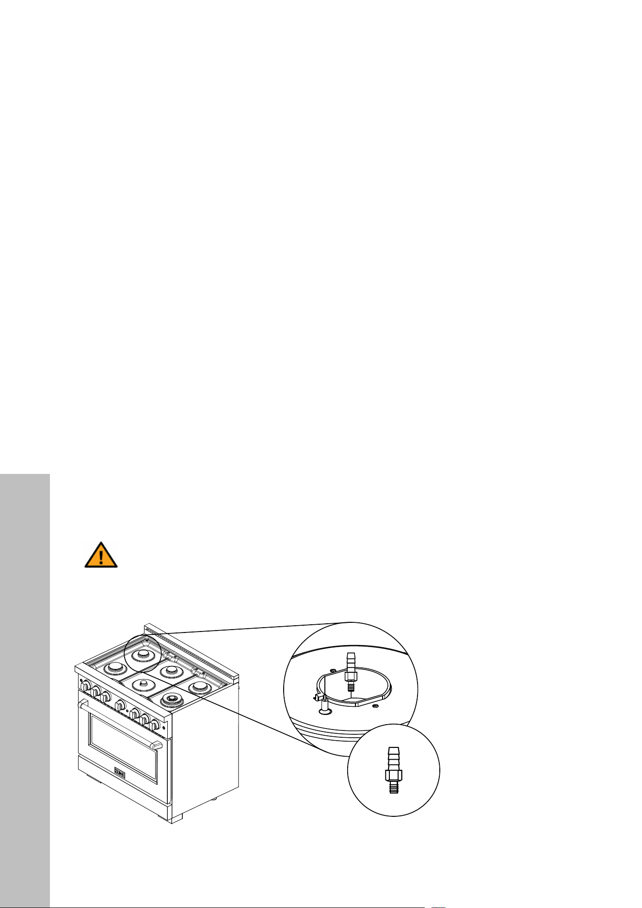
ADJUSTING THE REGULATOR PRESSURE
• Shut off the gas supply to the appliance by closing the manual shut-off valve (see images
below). Purge the gas line by pushing in the range knobs several times to ensure no more
gas is flowing through the system.
— 18 —
The pressure regulator located at the inlet of the appliance manifold must remain in the supply line regardless of Natural
(NG) or Liquid Propane (LP) gas is being used.
in length.
Installation
STEP 4 (Continued)
Gas Connection
DANGER:
Do not use a flame to check for leaks from gas connections. Checking for leaks with a flame may result in a
fire or explosion.
manifold pipe has not moved. A misalignment could cause the valve stems to rub on the control panel, resulting in
a gas leak at the valve.
pressure testing of that system at test pressures in excess of 1/2 psi (3.5 kPa or 12” water column).
Isolate the appliance from the gas supply piping system by closing its individual manual shut-off valve during any
pressure testing of the gas supply piping system at test pressures equal to or less than 1/2 psi (3.5 kPa or 12” water
column).
Figure 7
u
Shut off the main gas supply valve before removing
the old cooking appliance (if applicable) and leave it
forget to relight the pilots on other gas appliances
when you turn the gas back on.
v
Because har d piping restricts movement of the
appliance connector is recommended unless local
codes require a hard-piped connection. Never reuse
an old connector when installing a new appliance. If
the hard piping method is used, you must carefully
align the pipe.
To prevent gas leaks, use pipe joint compound
resistant to NG gases on all male external pipe
threads.
w
located on the bottom right hand corner underneath
the appliance.
x
When all connections have been made, be sur e all
appliance controls are in the off position and turn
on the main gas supply valve. Check for gas leaks
by using a 75% water,
25% dish washing soap
solution. If a gas leak
occurs, shut off gas
immediately, tighten all
connections, and retest
for leaks.
WARNINGS:
Examples of a qualified person include: licensed heating personnel, authorized gas company personnel, and
authorized service personnel.
— 19 —
Installation
STEP 5 (Optional)
(Must be done before Step 6 if converting to Propane)
Gas Conversion
This appliance can be used with Natural Gas or LP/Propane
Gas. It is shipped from the factory for use with Natural Gas. A
kit for converting to LP gas is supplied with your appliance.
u
When the appliance is converted for Liquid Petroleum
(LP) Gas, the LP gas supply is required to provide a
minimum of 10” to a maximum of 12” water column to
the appliance regulator.
Following LP Gas
Conversion, complete
Regulator Pressure”;
Burner Flames”; and
.
Adjusting the Regulator Pressure
v
w
Unscr ew the regulator cap with a wrench (see Figure
9).
Remove r etainer pin by pulling it out (see Figure 10).
Reverse the r etainer pin and snap it back into the
U
Scr ew the regulator cap back into the regulator and
DO NOT over-tighten (see Figures 12 and 13).
WARNINGS:
pages 4 to 10.
Step 4 can result in serious personal injury and
property damage.
The conversion must be performed by a qualified
service technician in accordance with the kit instruc-
tions and all local codes and requirements. Failure
to follow instructions could result in serious injury or
property damage. The qualified agency performing this
work assumes responsibility for the conversion.
Joint Joint
Flexible Connector
Off
On
Manual
Shut off
Valve
Pressure
Regulator
Flare
Union
Flare
Union
Gas Flow
Access
Cap
Figure 9
SGR30 and SGR36 models
SGR48 models
SGR30 and
SGR36 models
SGR48 models
SGR30 and SGR36 models
SGR48 models
SGR30 and SGR36 models
SGR48 models
• Unscrew the regulator access cap by hand or with a proper-sized pipe wrench (see
figure below).
— 19 —
Installation
STEP 5 (Optional)
(Must be done before Step 6 if converting to Propane)
Gas Conversion
This appliance can be used with Natural Gas or LP/Propane
Gas. It is shipped from the factory for use with Natural Gas. A
kit for converting to LP gas is supplied with your appliance.
u
When the appliance is converted for Liquid Petroleum
(LP) Gas, the LP gas supply is required to provide a
minimum of 10” to a maximum of 12” water column to
the appliance regulator.
Following LP Gas
Conversion, complete
Regulator Pressure”;
Burner Flames”; and
.
Adjusting the Regulator Pressure
v
w
Unscr ew the regulator cap with a wrench (see Figure
9).
Remove r etainer pin by pulling it out (see Figure 10).
Reverse the r etainer pin and snap it back into the
U
Scr ew the regulator cap back into the regulator and
DO NOT over-tighten (see Figures 12 and 13).
WARNINGS:
pages 4 to 10.
Step 4 can result in serious personal injury and
property damage.
The conversion must be performed by a qualified
service technician in accordance with the kit instruc-
tions and all local codes and requirements. Failure
to follow instructions could result in serious injury or
property damage. The qualified agency performing this
work assumes responsibility for the conversion.
Joint Joint
Flexible Connector
Off
On
Manual
Shut off
Valve
Pressure
Regulator
Flare
Union
Flare
Union
Gas Flow
Access
Cap
Figure 9
SGR30 and SGR36 models
SGR48 models
SGR30 and
SGR36 models
SGR48 models
SGR30 and SGR36 models
SGR48 models
SGR30 and SGR36 models
SGR48 models
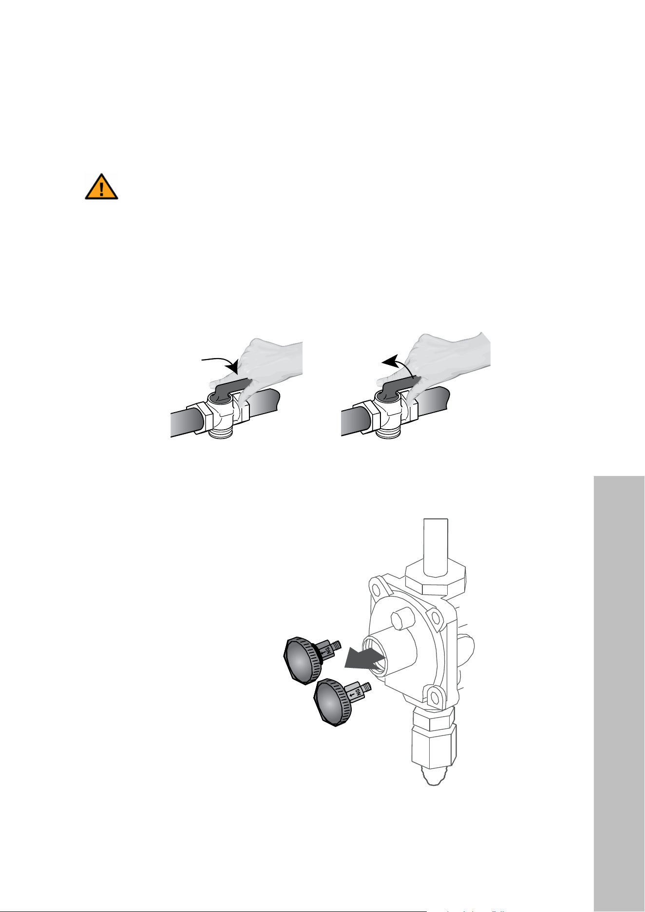
• Remove the regulator pin by pulling it out (see figure above). For SGR30 and SGR36
models, the pin will be gray in color. For SGR48 models, the pin will be gold.
Liquid Propane Conversion
35
INSTALLATION
LIQUID PROPANE CONVERSION (CONTINUED)
— 19 —
Installation
STEP 5 (Optional)
(Must be done before Step 6 if converting to Propane)
Gas Conversion
This appliance can be used with Natural Gas or LP/Propane
Gas. It is shipped from the factory for use with Natural Gas. A
kit for converting to LP gas is supplied with your appliance.
u
When the appliance is converted for Liquid Petroleum
(LP) Gas, the LP gas supply is required to provide a
minimum of 10” to a maximum of 12” water column to
the appliance regulator.
Following LP Gas
Conversion, complete
Regulator Pressure”;
Burner Flames”; and
.
Adjusting the Regulator Pressure
v
w
Unscr ew the regulator cap with a wrench (see Figure
9).
Remove r etainer pin by pulling it out (see Figure 10).
Reverse the r etainer pin and snap it back into the
U
Scr ew the regulator cap back into the regulator and
DO NOT over-tighten (see Figures 12 and 13).
WARNINGS:
pages 4 to 10.
Step 4 can result in serious personal injury and
property damage.
The conversion must be performed by a qualified
service technician in accordance with the kit instruc-
tions and all local codes and requirements. Failure
to follow instructions could result in serious injury or
property damage. The qualified agency performing this
work assumes responsibility for the conversion.
Joint Joint
Flexible Connector
Off
On
Manual
Shut off
Valve
Pressure
Regulator
Flare
Union
Flare
Union
Gas Flow
Access
Cap
Figure 9
SGR30 and SGR36 models
SGR48 models
SGR30 and
SGR36 models
SGR48 models
SGR30 and SGR36 models
SGR48 models
SGR30 and SGR36 models
SGR48 models
• Unscrew the retainer pin, reverse it, and screw back into the regulator cap as outlined
in the figures above and below. For SGR30 and SGR36 models, the gray pin is not
attached to a spring. For SGR48 models, the gold pin is attached to a spring. When
reversing the SGR48 pin, ensure the spring is snug when tightening.
— 19 —
Installation
STEP 5 (Optional)
(Must be done before Step 6 if converting to Propane)
Gas Conversion
This appliance can be used with Natural Gas or LP/Propane
Gas. It is shipped from the factory for use with Natural Gas. A
kit for converting to LP gas is supplied with your appliance.
u
When the appliance is converted for Liquid Petroleum
(LP) Gas, the LP gas supply is required to provide a
minimum of 10” to a maximum of 12” water column to
the appliance regulator.
Following LP Gas
Conversion, complete
Regulator Pressure”;
Burner Flames”; and
.
Adjusting the Regulator Pressure
v
w
Unscr ew the regulator cap with a wrench (see Figure
9).
Remove r etainer pin by pulling it out (see Figure 10).
Reverse the r etainer pin and snap it back into the
U
Scr ew the regulator cap back into the regulator and
DO NOT over-tighten (see Figures 12 and 13).
WARNINGS:
pages 4 to 10.
Step 4 can result in serious personal injury and
property damage.
The conversion must be performed by a qualified
service technician in accordance with the kit instruc-
tions and all local codes and requirements. Failure
to follow instructions could result in serious injury or
property damage. The qualified agency performing this
work assumes responsibility for the conversion.
Joint Joint
Flexible Connector
Off
On
Manual
Shut off
Valve
Pressure
Regulator
Flare
Union
Flare
Union
Gas Flow
Access
Cap
Figure 9
SGR30 and SGR36 models
SGR48 models
SGR30 and
SGR36 models
SGR48 models
SGR30 and SGR36 models
SGR48 models
SGR30 and SGR36 models
SGR48 models
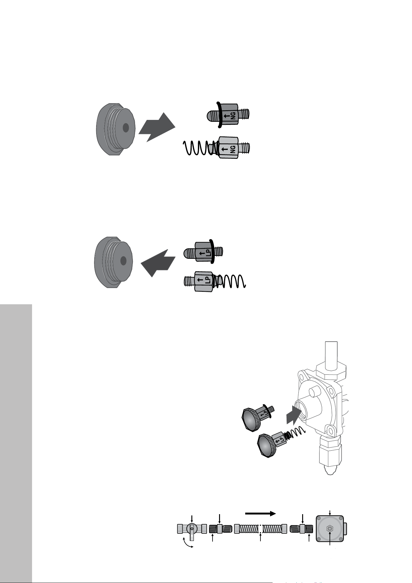
• Screw the regulator access cap back into the regulator and re-attach it to the nipple and
flare union as shown. DO NOT over-tighten (see figures below).
— 19 —
Installation
STEP 5 (Optional)
(Must be done before Step 6 if converting to Propane)
Gas Conversion
This appliance can be used with Natural Gas or LP/Propane
Gas. It is shipped from the factory for use with Natural Gas. A
kit for converting to LP gas is supplied with your appliance.
u
When the appliance is converted for Liquid Petroleum
(LP) Gas, the LP gas supply is required to provide a
minimum of 10” to a maximum of 12” water column to
the appliance regulator.
Following LP Gas
Conversion, complete
Regulator Pressure”;
Burner Flames”; and
.
Adjusting the Regulator Pressure
v
w
Unscr ew the regulator cap with a wrench (see Figure
9).
Remove r etainer pin by pulling it out (see Figure 10).
Reverse the r etainer pin and snap it back into the
U
Scr ew the regulator cap back into the regulator and
DO NOT over-tighten (see Figures 12 and 13).
WARNINGS:
pages 4 to 10.
Step 4 can result in serious personal injury and
property damage.
The conversion must be performed by a qualified
service technician in accordance with the kit instruc-
tions and all local codes and requirements. Failure
to follow instructions could result in serious injury or
property damage. The qualified agency performing this
work assumes responsibility for the conversion.
Joint Joint
Flexible Connector
Off
On
Manual
Shut off
Valve
Pressure
Regulator
Flare
Union
Flare
Union
Gas Flow
Access
Cap
Figure 9
SGR30 and SGR36 models
SGR48 models
SGR30 and
SGR36 models
SGR48 models
SGR30 and SGR36 models
SGR48 models
SGR30 and SGR36 models
SGR48 models
NOTE: The pressure
regulator and cap come
pre-installed on the unit;
the other parts in the
figure at bottom right
are not supplied and are
the responsibility of the
customer to obtain for a
qualified installer to install
to ensure a safe and
effective gas hook-up.
Liquid Propane Conversion
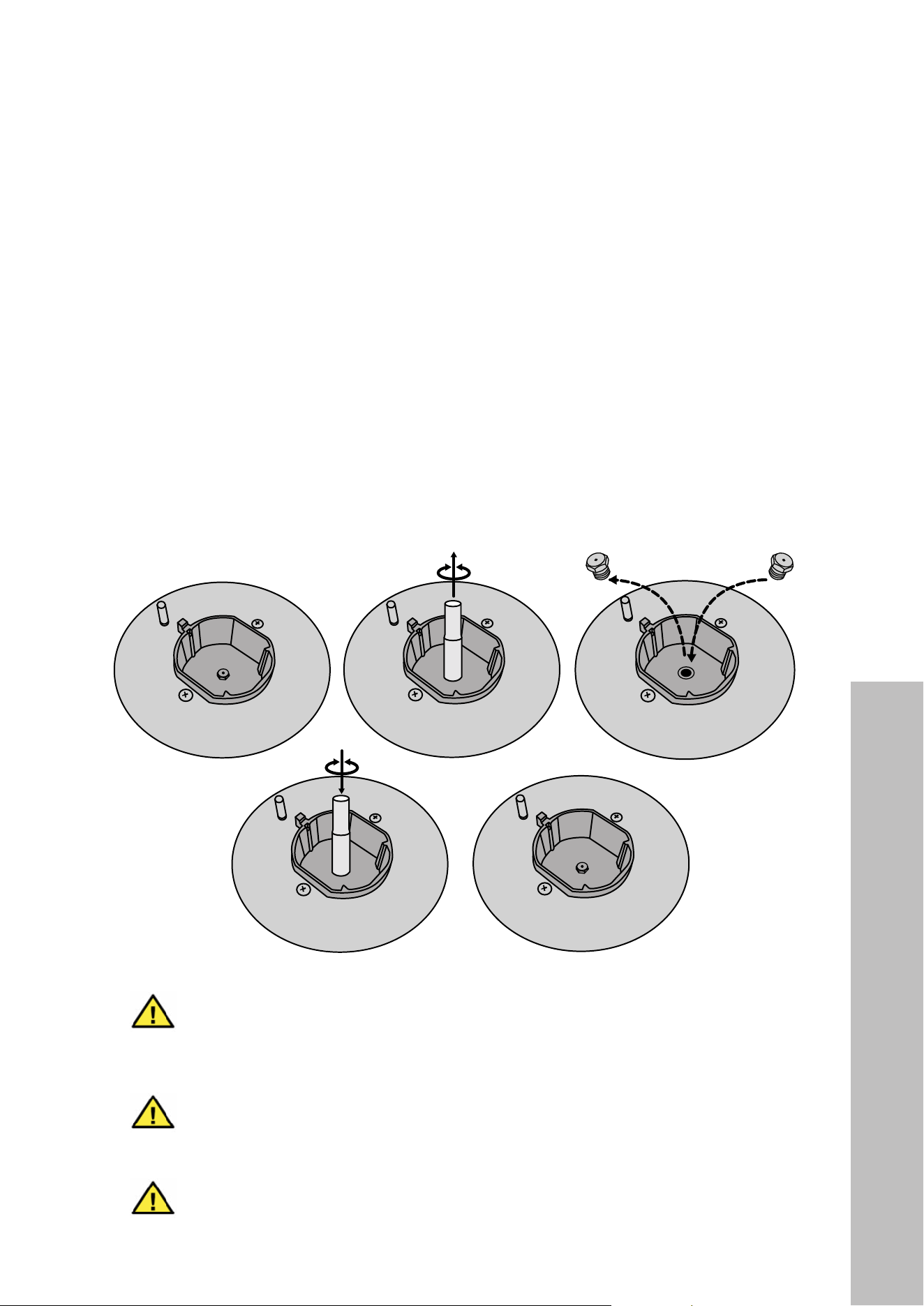
36
INSTALLATION
LIQUID PROPANE CONVERSION (CONTINUED)
CHANGING BURNER ORIFICES
• After removing the burner grates, burner caps, and burner spreads, use a 7mm nut
driver or wrench to remove the existing natural gas orifices as outlined in the figure
below. Carefully read and observe each orifice label for correct location.
• IMPORTANT: DO NOT force or over-tighten orifices, as doing so may damage the
burner base and affect the flame.
• Not indicated in the images below is the dual burner on the SGR36 and SGR48 series
ranges. Each dual burner includes 3 orifices — 1 in the middle, like below, and 2 on the
side. Use a 7mm wrench to remove the side orifices.
— 20 —
STEP 5 (Continued)
Gas Conversion
Changing Burner Nozzles
INSTALLATION TIP: To prevent any omissions,
remove ALL existing Natural Gas nozzles before
replacing them with the LP nozzles.
V
Remove the bur ner grates, burner caps and burner
rings. Using a 7mm nut driver, remove ALL the
existing Natural Gas burner nozzles. Carefully read
and observe each nozzle label for correct location
(DO NOT force or over-tighten nozzles as doing so
Installation
Figure 14
WARNING:
Save the natural gas orifices removed from the
appliance for possible future conversions to natural
gas. You should use the following process to convert
to Natural gas. Take extra care when handling steel
parts.
WARNING:
Care should be taken when removing and replacing
gas components. Use proper support to prevent
damage to components.
NG LPG
7 mm
7 mm
116
74
1.09
116
74
1.09
116
74
1.09
116
74
1.09
116
74
1.09
116
74
1.09
116
74
1.09
116
74
1.09
116
116
74
116
74
89
116
90
74
1.09
1.4
89
116
90
74
1.09
1.4
116
74
1.09
WARNING
Save the orifices removed from the appliance for future use. You should use
the same process to re-convert to natural gas. Take extra care when handling
steel parts.
WARNING
Conserver les orifices retirés de l’appareil en vue d’une utilisation ultérieure.
WARNING
Care should be taken when removing and replacing gas components. Use
proper support to prevent damage to components.
Liquid Propane Conversion
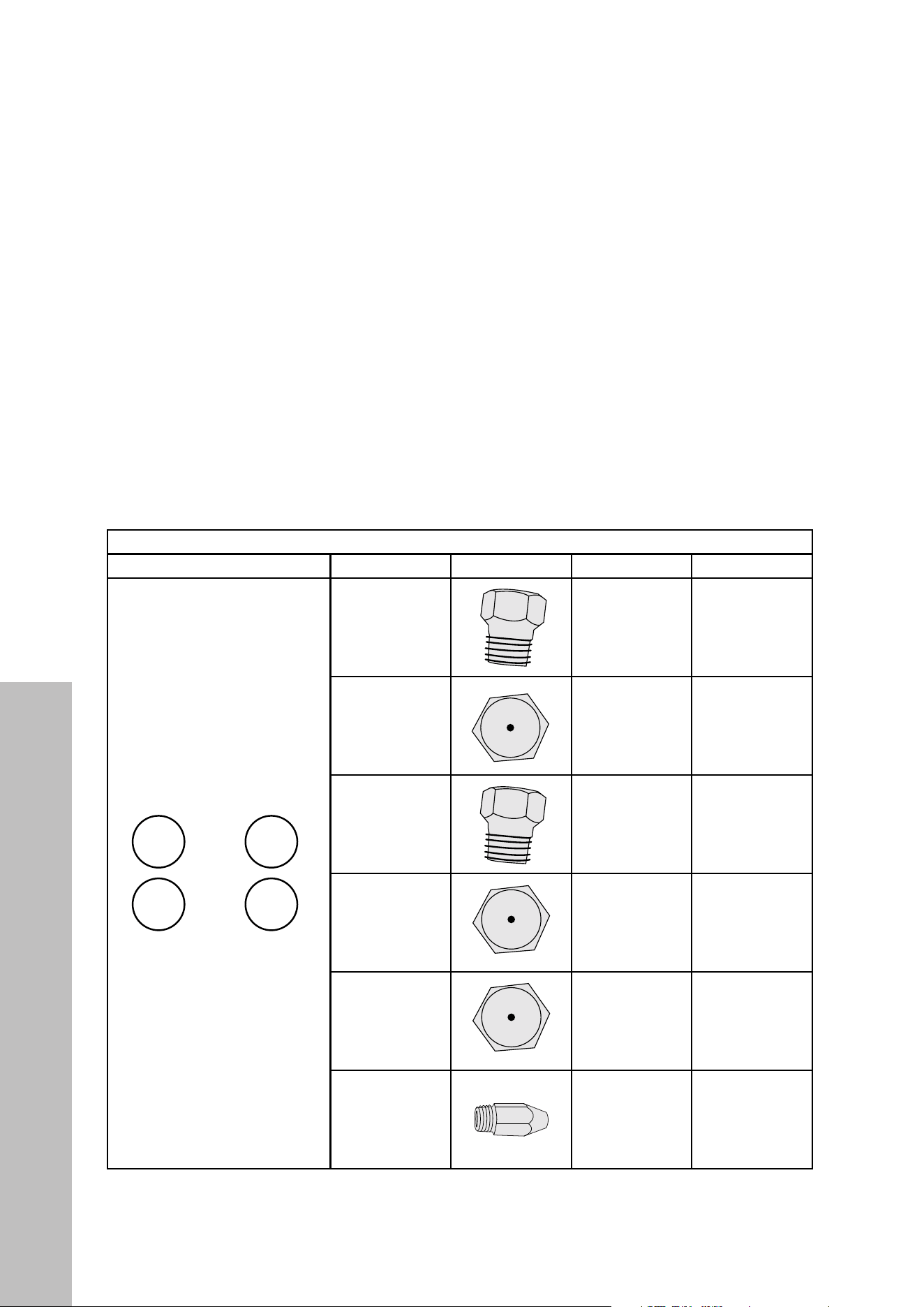
37
INSTALLATION
LIQUID PROPANE CONVERSION (CONTINUED)
ORIFICE NUMBERS
INSTALLATION TIP: To prevent any mistakes during the conversion, remove ALL existing
natural gas orifices first before replacing them with the LPG orifices.
IMPORTANT: Each orifice has a number indicating its flow diameter printed on the body.
Install the proper orifice in the exact locations as noted in the illustrations and table below
for SGR30 series ranges and on the following pages for SGR36 and SGR48 models.
SGR30 SERIES ORIFICES
BURNER LAYOUT BURNER PICTURE NG LPG
— 21 —
STEP 5 (Continued)
Gas Conversion
Changing Burner Nozzles
INSTALLATION TIP: To prevent any omissions,
remove ALL existing Natural Gas nozzles before
replacing them with the LP nozzles.
W diameter printed on the body. Install the proper
nozzles in the exact locations as noted in the
illustrations and table below (see Figure 15A, 15B or
15C).
Installation
1.16
0.9
1.16
0.9
LPGNG
1.36
1.79
1.79
1.36
Burner
B
C
D
A
D
C
B
A
Broil
Oven
0.941.42
1.42.13
0.89*2+0.53
0.74
0.9
NG
1.57
1.36*2+0.73
1.07
1.36
Burner
B
C
D
A
LPG
1.0
D
C
B
A
F
E
1.161.79E
0.91.36F
Broil
Oven
0.941.42
1.42.13
Débit d'entrée du bruleur (BTU/h) / Burner input rating
0.74
0.9
NG
1.57
1.36*2+0.73
1.07
1.36
Burner
B
C
D
A
1.0
0.89*2+0.53
LPG
D
C
B
A
F
E
H
G
Broil
Oven
0.941.42
1.42.13
0.74
0.9
1.57
1.36*2+0.73
1.07
1.36
F
G
H
E
1.0
0.89*2+0.53
18” Oven 1.091.68
30”
36”
48”
Figure 15C
53
89
116
100
90
74
1.09
1.4
0.94
53
89
116
100
90
74
1.09
1.4
0.94
53
89
116
100
90
1.09
1.4
0.94
53
89
100
90
1.4
0.94
53
89
100
90
1.4
0.94
53
89
116
100
90
74
1.09
1.4
0.94
53
89
116
100
90
74
0.94
53
89
116
100
90
74
1.09
1.4
0.94
53
89
100
90
1.4
0.94
53
89
100
90
1.4
0.94
Figure 15B
Figure 15A
53
89
116
100
90
74
1.09
1.4
0.94
53
89
100
90
1.4
0.94
53
89
116
100
90
74
1.09
1.4
0.94
53
89
100
90
1.4
0.94
53
89
116
53
89
116
100
90
74
53
89
116
100
90
53
89
100
90
1.4
0.94
53
89
116
100
90
74
0.94
53
89
116
100
90
74
1.09
1.4
0.94
53
89
100
90
1.4
0.94
53
89
53
89
100
90
53
89
100
90
53
100
0.94
53
89
116
100
90
74
0.94
53
100
0.94
53
89
116
100
90
74
1.09
1.4
0.94
53
89
116
100
90
74
1.09
1.4
0.94
53
89
100
90
1.4
0.94
53
89
116
100
90
74
1.09
1.4
0.94
A
B
C
D
B
C
D
AE
F
B
C
D
A
G
H F
E
A
— 21 —
STEP 5 (Continued)
Gas Conversion
Changing Burner Nozzles
INSTALLATION TIP: To prevent any omissions,
remove ALL existing Natural Gas nozzles before
replacing them with the LP nozzles.
W diameter printed on the body. Install the proper
nozzles in the exact locations as noted in the
illustrations and table below (see Figure 15A, 15B or
15C).
Installation
1.16
0.9
1.16
0.9
LPGNG
1.36
1.79
1.79
1.36
Burner
B
C
D
A
D
C
B
A
Broil
Oven
0.941.42
1.42.13
0.89*2+0.53
0.74
0.9
NG
1.57
1.36*2+0.73
1.07
1.36
Burner
B
C
D
A
LPG
1.0
D
C
B
A
F
E
1.161.79E
0.91.36F
Broil
Oven
0.941.42
1.42.13
Débit d'entrée du bruleur (BTU/h) / Burner input rating
0.74
0.9
NG
1.57
1.36*2+0.73
1.07
1.36
Burner
B
C
D
A
1.0
0.89*2+0.53
LPG
D
C
B
A
F
E
H
G
Broil
Oven
0.941.42
1.42.13
0.74
0.9
1.57
1.36*2+0.73
1.07
1.36
F
G
H
E
1.0
0.89*2+0.53
18” Oven 1.091.68
30”
36”
48”
Figure 15C
53
89
116
100
90
74
1.09
1.4
0.94
53
89
116
100
90
74
1.09
1.4
0.94
53
89
116
100
90
1.09
1.4
0.94
53
89
100
90
1.4
0.94
53
89
100
90
1.4
0.94
53
89
116
100
90
74
1.09
1.4
0.94
53
89
116
100
90
74
0.94
53
89
116
100
90
74
1.09
1.4
0.94
53
89
100
90
1.4
0.94
53
89
100
90
1.4
0.94
Figure 15B
Figure 15A
53
89
116
100
90
74
1.09
1.4
0.94
53
89
100
90
1.4
0.94
53
89
116
100
90
74
1.09
1.4
0.94
53
89
100
90
1.4
0.94
53
89
116
53
89
116
100
90
74
53
89
116
100
90
53
89
100
90
1.4
0.94
53
89
116
100
90
74
0.94
53
89
116
100
90
74
1.09
1.4
0.94
53
89
100
90
1.4
0.94
53
89
53
89
100
90
53
89
100
90
53
100
0.94
53
89
116
100
90
74
0.94
53
100
0.94
53
89
116
100
90
74
1.09
1.4
0.94
53
89
116
100
90
74
1.09
1.4
0.94
53
89
100
90
1.4
0.94
53
89
116
100
90
74
1.09
1.4
0.94
A
B
C
D
B
C
D
AE
F
B
C
D
A
G
H F
E
1.79 1.16
B
— 21 —
STEP 5 (Continued)
Gas Conversion
Changing Burner Nozzles
INSTALLATION TIP: To prevent any omissions,
remove ALL existing Natural Gas nozzles before
replacing them with the LP nozzles.
W diameter printed on the body. Install the proper
nozzles in the exact locations as noted in the
illustrations and table below (see Figure 15A, 15B or
15C).
Installation
1.16
0.9
1.16
0.9
LPGNG
1.36
1.79
1.79
1.36
Burner
B
C
D
A
D
C
B
A
Broil
Oven
0.941.42
1.42.13
0.89*2+0.53
0.74
0.9
NG
1.57
1.36*2+0.73
1.07
1.36
Burner
B
C
D
A
LPG
1.0
D
C
B
A
F
E
1.161.79E
0.91.36F
Broil
Oven
0.941.42
1.42.13
Débit d'entrée du bruleur (BTU/h) / Burner input rating
0.74
0.9
NG
1.57
1.36*2+0.73
1.07
1.36
Burner
B
C
D
A
1.0
0.89*2+0.53
LPG
D
C
B
A
F
E
H
G
Broil
Oven
0.941.42
1.42.13
0.74
0.9
1.57
1.36*2+0.73
1.07
1.36
F
G
H
E
1.0
0.89*2+0.53
18” Oven 1.091.68
30”
36”
48”
Figure 15C
53
89
116
100
90
74
1.09
1.4
0.94
53
89
116
100
90
74
1.09
1.4
0.94
53
89
116
100
90
1.09
1.4
0.94
53
89
100
90
1.4
0.94
53
89
100
90
1.4
0.94
53
89
116
100
90
74
1.09
1.4
0.94
53
89
116
100
90
74
0.94
53
89
116
100
90
74
1.09
1.4
0.94
53
89
100
90
1.4
0.94
53
89
100
90
1.4
0.94
Figure 15B
Figure 15A
53
89
116
100
90
74
1.09
1.4
0.94
53
89
100
90
1.4
0.94
53
89
116
100
90
74
1.09
1.4
0.94
53
89
100
90
1.4
0.94
53
89
116
53
89
116
100
90
74
53
89
116
100
90
53
89
100
90
1.4
0.94
53
89
116
100
90
74
0.94
53
89
116
100
90
74
1.09
1.4
0.94
53
89
100
90
1.4
0.94
53
89
53
89
100
90
53
89
100
90
53
100
0.94
53
89
116
100
90
74
0.94
53
100
0.94
53
89
116
100
90
74
1.09
1.4
0.94
53
89
116
100
90
74
1.09
1.4
0.94
53
89
100
90
1.4
0.94
53
89
116
100
90
74
1.09
1.4
0.94
A
B
C
D
B
C
D
AE
F
B
C
D
A
G
H F
E
1.36 0.90
C
— 21 —
STEP 5 (Continued)
Gas Conversion
Changing Burner Nozzles
INSTALLATION TIP: To prevent any omissions,
remove ALL existing Natural Gas nozzles before
replacing them with the LP nozzles.
W diameter printed on the body. Install the proper
nozzles in the exact locations as noted in the
illustrations and table below (see Figure 15A, 15B or
15C).
Installation
1.16
0.9
1.16
0.9
LPGNG
1.36
1.79
1.79
1.36
Burner
B
C
D
A
D
C
B
A
Broil
Oven
0.941.42
1.42.13
0.89*2+0.53
0.74
0.9
NG
1.57
1.36*2+0.73
1.07
1.36
Burner
B
C
D
A
LPG
1.0
D
C
B
A
F
E
1.161.79E
0.91.36F
Broil
Oven
0.941.42
1.42.13
Débit d'entrée du bruleur (BTU/h) / Burner input rating
0.74
0.9
NG
1.57
1.36*2+0.73
1.07
1.36
Burner
B
C
D
A
1.0
0.89*2+0.53
LPG
D
C
B
A
F
E
H
G
Broil
Oven
0.941.42
1.42.13
0.74
0.9
1.57
1.36*2+0.73
1.07
1.36
F
G
H
E
1.0
0.89*2+0.53
18” Oven 1.091.68
30”
36”
48”
Figure 15C
53
89
116
100
90
74
1.09
1.4
0.94
53
89
116
100
90
74
1.09
1.4
0.94
53
89
116
100
90
1.09
1.4
0.94
53
89
100
90
1.4
0.94
53
89
100
90
1.4
0.94
53
89
116
100
90
74
1.09
1.4
0.94
53
89
116
100
90
74
0.94
53
89
116
100
90
74
1.09
1.4
0.94
53
89
100
90
1.4
0.94
53
89
100
90
1.4
0.94
Figure 15B
Figure 15A
53
89
116
100
90
74
1.09
1.4
0.94
53
89
100
90
1.4
0.94
53
89
116
100
90
74
1.09
1.4
0.94
53
89
100
90
1.4
0.94
53
89
116
53
89
116
100
90
74
53
89
116
100
90
53
89
100
90
1.4
0.94
53
89
116
100
90
74
0.94
53
89
116
100
90
74
1.09
1.4
0.94
53
89
100
90
1.4
0.94
53
89
53
89
100
90
53
89
100
90
53
100
0.94
53
89
116
100
90
74
0.94
53
100
0.94
53
89
116
100
90
74
1.09
1.4
0.94
53
89
116
100
90
74
1.09
1.4
0.94
53
89
100
90
1.4
0.94
53
89
116
100
90
74
1.09
1.4
0.94
A
B
C
D
B
C
D
AE
F
B
C
D
A
G
H F
E
1.79 1.16
D
— 21 —
STEP 5 (Continued)
Gas Conversion
Changing Burner Nozzles
INSTALLATION TIP: To prevent any omissions,
remove ALL existing Natural Gas nozzles before
replacing them with the LP nozzles.
W diameter printed on the body. Install the proper
nozzles in the exact locations as noted in the
illustrations and table below (see Figure 15A, 15B or
15C).
Installation
1.16
0.9
1.16
0.9
LPGNG
1.36
1.79
1.79
1.36
Burner
B
C
D
A
D
C
B
A
Broil
Oven
0.941.42
1.42.13
0.89*2+0.53
0.74
0.9
NG
1.57
1.36*2+0.73
1.07
1.36
Burner
B
C
D
A
LPG
1.0
D
C
B
A
F
E
1.161.79E
0.91.36F
Broil
Oven
0.941.42
1.42.13
Débit d'entrée du bruleur (BTU/h) / Burner input rating
0.74
0.9
NG
1.57
1.36*2+0.73
1.07
1.36
Burner
B
C
D
A
1.0
0.89*2+0.53
LPG
D
C
B
A
F
E
H
G
Broil
Oven
0.941.42
1.42.13
0.74
0.9
1.57
1.36*2+0.73
1.07
1.36
F
G
H
E
1.0
0.89*2+0.53
18” Oven 1.091.68
30”
36”
48”
Figure 15C
53
89
116
100
90
74
1.09
1.4
0.94
53
89
116
100
90
74
1.09
1.4
0.94
53
89
116
100
90
1.09
1.4
0.94
53
89
100
90
1.4
0.94
53
89
100
90
1.4
0.94
53
89
116
100
90
74
1.09
1.4
0.94
53
89
116
100
90
74
0.94
53
89
116
100
90
74
1.09
1.4
0.94
53
89
100
90
1.4
0.94
53
89
100
90
1.4
0.94
Figure 15B
Figure 15A
53
89
116
100
90
74
1.09
1.4
0.94
53
89
100
90
1.4
0.94
53
89
116
100
90
74
1.09
1.4
0.94
53
89
100
90
1.4
0.94
53
89
116
53
89
116
100
90
74
53
89
116
100
90
53
89
100
90
1.4
0.94
53
89
116
100
90
74
0.94
53
89
116
100
90
74
1.09
1.4
0.94
53
89
100
90
1.4
0.94
53
89
53
89
100
90
53
89
100
90
53
100
0.94
53
89
116
100
90
74
0.94
53
100
0.94
53
89
116
100
90
74
1.09
1.4
0.94
53
89
116
100
90
74
1.09
1.4
0.94
53
89
100
90
1.4
0.94
53
89
116
100
90
74
1.09
1.4
0.94
A
B
C
D
B
C
D
AE
F
B
C
D
A
G
H F
E
1.36 0.90
OVEN BROIL
— 21 —
STEP 5 (Continued)
Gas Conversion
Changing Burner Nozzles
INSTALLATION TIP: To prevent any omissions,
remove ALL existing Natural Gas nozzles before
replacing them with the LP nozzles.
W diameter printed on the body. Install the proper
nozzles in the exact locations as noted in the
illustrations and table below (see Figure 15A, 15B or
15C).
Installation
1.16
0.9
1.16
0.9
LPGNG
1.36
1.79
1.79
1.36
Burner
B
C
D
A
D
C
B
A
Broil
Oven
0.941.42
1.42.13
0.89*2+0.53
0.74
0.9
NG
1.57
1.36*2+0.73
1.07
1.36
Burner
B
C
D
A
LPG
1.0
D
C
B
A
F
E
1.161.79E
0.91.36F
Broil
Oven
0.941.42
1.42.13
Débit d'entrée du bruleur (BTU/h) / Burner input rating
0.74
0.9
NG
1.57
1.36*2+0.73
1.07
1.36
Burner
B
C
D
A
1.0
0.89*2+0.53
LPG
D
C
B
A
F
E
H
G
Broil
Oven
0.941.42
1.42.13
0.74
0.9
1.57
1.36*2+0.73
1.07
1.36
F
G
H
E
1.0
0.89*2+0.53
18” Oven 1.091.68
30”
36”
48”
Figure 15C
53
89
116
100
90
74
1.09
1.4
0.94
53
89
116
100
90
74
1.09
1.4
0.94
53
89
116
100
90
1.09
1.4
0.94
53
89
100
90
1.4
0.94
53
89
100
90
1.4
0.94
53
89
116
100
90
74
1.09
1.4
0.94
53
89
116
100
90
74
0.94
53
89
116
100
90
74
1.09
1.4
0.94
53
89
100
90
1.4
0.94
53
89
100
90
1.4
0.94
Figure 15B
Figure 15A
53
89
116
100
90
74
1.09
1.4
0.94
53
89
100
90
1.4
0.94
53
89
116
100
90
74
1.09
1.4
0.94
53
89
100
90
1.4
0.94
53
89
116
53
89
116
100
90
74
53
89
116
100
90
53
89
100
90
1.4
0.94
53
89
116
100
90
74
0.94
53
89
116
100
90
74
1.09
1.4
0.94
53
89
100
90
1.4
0.94
53
89
53
89
100
90
53
89
100
90
53
100
0.94
53
89
116
100
90
74
0.94
53
100
0.94
53
89
116
100
90
74
1.09
1.4
0.94
53
89
116
100
90
74
1.09
1.4
0.94
53
89
100
90
1.4
0.94
53
89
116
100
90
74
1.09
1.4
0.94
A
B
C
D
B
C
D
AE
F
B
C
D
A
G
H F
E
1.42 0.94
OVEN BAKE
— 21 —
STEP 5 (Continued)
Gas Conversion
Changing Burner Nozzles
INSTALLATION TIP: To prevent any omissions,
remove ALL existing Natural Gas nozzles before
replacing them with the LP nozzles.
W diameter printed on the body. Install the proper
nozzles in the exact locations as noted in the
illustrations and table below (see Figure 15A, 15B or
15C).
Installation
1.16
0.9
1.16
0.9
LPGNG
1.36
1.79
1.79
1.36
Burner
B
C
D
A
D
C
B
A
Broil
Oven
0.941.42
1.42.13
0.89*2+0.53
0.74
0.9
NG
1.57
1.36*2+0.73
1.07
1.36
Burner
B
C
D
A
LPG
1.0
D
C
B
A
F
E
1.161.79E
0.91.36F
Broil
Oven
0.941.42
1.42.13
Débit d'entrée du bruleur (BTU/h) / Burner input rating
0.74
0.9
NG
1.57
1.36*2+0.73
1.07
1.36
Burner
B
C
D
A
1.0
0.89*2+0.53
LPG
D
C
B
A
F
E
H
G
Broil
Oven
0.941.42
1.42.13
0.74
0.9
1.57
1.36*2+0.73
1.07
1.36
F
G
H
E
1.0
0.89*2+0.53
18” Oven 1.091.68
30”
36”
48”
Figure 15C
53
89
116
100
90
74
1.09
1.4
0.94
53
89
116
100
90
74
1.09
1.4
0.94
53
89
116
100
90
1.09
1.4
0.94
53
89
100
90
1.4
0.94
53
89
100
90
1.4
0.94
53
89
116
100
90
74
1.09
1.4
0.94
53
89
116
100
90
74
0.94
53
89
116
100
90
74
1.09
1.4
0.94
53
89
100
90
1.4
0.94
53
89
100
90
1.4
0.94
Figure 15B
Figure 15A
53
89
116
100
90
74
1.09
1.4
0.94
53
89
100
90
1.4
0.94
53
89
116
100
90
74
1.09
1.4
0.94
53
89
100
90
1.4
0.94
53
89
116
53
89
116
100
90
74
53
89
116
100
90
53
89
100
90
1.4
0.94
53
89
116
100
90
74
0.94
53
89
116
100
90
74
1.09
1.4
0.94
53
89
100
90
1.4
0.94
53
89
53
89
100
90
53
89
100
90
53
100
0.94
53
89
116
100
90
74
0.94
53
100
0.94
53
89
116
100
90
74
1.09
1.4
0.94
53
89
116
100
90
74
1.09
1.4
0.94
53
89
100
90
1.4
0.94
53
89
116
100
90
74
1.09
1.4
0.94
A
B
C
D
B
C
D
AE
F
B
C
D
A
G
H F
E
2.13 1.40
Liquid Propane Conversion
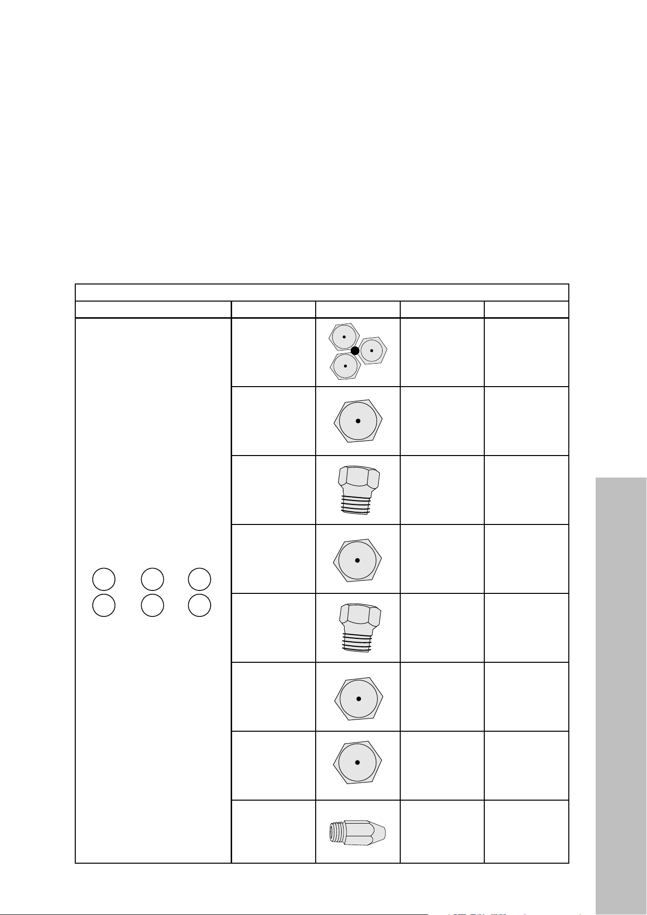
38
INSTALLATION
LIQUID PROPANE CONVERSION (CONTINUED)
IMPORTANT: The SGR36 series ranges have 6 cooktop burners compared to 4 on the
SGR30 series ranges. Additionally, the SGR36 series ranges come with a special dual
burner (A). This burner includes 3 orifices to remove/replace — 1 in the middle and 2
on the side.
SGR36 SERIES ORIFICES
BURNER LAYOUT BURNER PICTURE NG LPG
— 21 —
STEP 5 (Continued)
Gas Conversion
Changing Burner Nozzles
INSTALLATION TIP: To prevent any omissions,
remove ALL existing Natural Gas nozzles before
replacing them with the LP nozzles.
W diameter printed on the body. Install the proper
nozzles in the exact locations as noted in the
illustrations and table below (see Figure 15A, 15B or
15C).
Installation
1.16
0.9
1.16
0.9
LPGNG
1.36
1.79
1.79
1.36
Burner
B
C
D
A
D
C
B
A
Broil
Oven
0.941.42
1.42.13
0.89*2+0.53
0.74
0.9
NG
1.57
1.36*2+0.73
1.07
1.36
Burner
B
C
D
A
LPG
1.0
D
C
B
A
F
E
1.161.79E
0.91.36F
Broil
Oven
0.941.42
1.42.13
Débit d'entrée du bruleur (BTU/h) / Burner input rating
0.74
0.9
NG
1.57
1.36*2+0.73
1.07
1.36
Burner
B
C
D
A
1.0
0.89*2+0.53
LPG
D
C
B
A
F
E
H
G
Broil
Oven
0.941.42
1.42.13
0.74
0.9
1.57
1.36*2+0.73
1.07
1.36
F
G
H
E
1.0
0.89*2+0.53
18” Oven 1.091.68
30”
36”
48”
Figure 15C
53
89
116
100
90
74
1.09
1.4
0.94
53
89
116
100
90
74
1.09
1.4
0.94
53
89
116
100
90
1.09
1.4
0.94
53
89
100
90
1.4
0.94
53
89
100
90
1.4
0.94
53
89
116
100
90
74
1.09
1.4
0.94
53
89
116
100
90
74
0.94
53
89
116
100
90
74
1.09
1.4
0.94
53
89
100
90
1.4
0.94
53
89
100
90
1.4
0.94
Figure 15B
Figure 15A
53
89
116
100
90
74
1.09
1.4
0.94
53
89
100
90
1.4
0.94
53
89
116
100
90
74
1.09
1.4
0.94
53
89
100
90
1.4
0.94
53
89
116
53
89
116
100
90
74
53
89
116
100
90
53
89
100
90
1.4
0.94
53
89
116
100
90
74
0.94
53
89
116
100
90
74
1.09
1.4
0.94
53
89
100
90
1.4
0.94
53
89
53
89
100
90
53
89
100
90
53
100
0.94
53
89
116
100
90
74
0.94
53
100
0.94
53
89
116
100
90
74
1.09
1.4
0.94
53
89
116
100
90
74
1.09
1.4
0.94
53
89
100
90
1.4
0.94
53
89
116
100
90
74
1.09
1.4
0.94
A
B
C
D
B
C
D
AE
F
B
C
D
A
G
H F
E
A
— 21 —
STEP 5 (Continued)
Gas Conversion
Changing Burner Nozzles
INSTALLATION TIP: To prevent any omissions,
remove ALL existing Natural Gas nozzles before
replacing them with the LP nozzles.
W diameter printed on the body. Install the proper
nozzles in the exact locations as noted in the
illustrations and table below (see Figure 15A, 15B or
15C).
Installation
1.16
0.9
1.16
0.9
LPGNG
1.36
1.79
1.79
1.36
Burner
B
C
D
A
D
C
B
A
Broil
Oven
0.941.42
1.42.13
0.89*2+0.53
0.74
0.9
NG
1.57
1.36*2+0.73
1.07
1.36
Burner
B
C
D
A
LPG
1.0
D
C
B
A
F
E
1.161.79E
0.91.36F
Broil
Oven
0.941.42
1.42.13
Débit d'entrée du bruleur (BTU/h) / Burner input rating
0.74
0.9
NG
1.57
1.36*2+0.73
1.07
1.36
Burner
B
C
D
A
1.0
0.89*2+0.53
LPG
D
C
B
A
F
E
H
G
Broil
Oven
0.941.42
1.42.13
0.74
0.9
1.57
1.36*2+0.73
1.07
1.36
F
G
H
E
1.0
0.89*2+0.53
18” Oven 1.091.68
30”
36”
48”
Figure 15C
53
89
116
100
90
74
1.09
1.4
0.94
53
89
116
100
90
74
1.09
1.4
0.94
53
89
116
100
90
1.09
1.4
0.94
53
89
100
90
1.4
0.94
53
89
100
90
1.4
0.94
53
89
116
100
90
74
1.09
1.4
0.94
53
89
116
100
90
74
0.94
53
89
116
100
90
74
1.09
1.4
0.94
53
89
100
90
1.4
0.94
53
89
100
90
1.4
0.94
Figure 15B
Figure 15A
53
89
116
100
90
74
1.09
1.4
0.94
53
89
100
90
1.4
0.94
53
89
116
100
90
74
1.09
1.4
0.94
53
89
100
90
1.4
0.94
53
89
116
53
89
116
100
90
74
53
89
116
100
90
53
89
100
90
1.4
0.94
53
89
116
100
90
74
0.94
53
89
116
100
90
74
1.09
1.4
0.94
53
89
100
90
1.4
0.94
53
89
53
89
100
90
53
89
100
90
53
100
0.94
53
89
116
100
90
74
0.94
53
100
0.94
53
89
116
100
90
74
1.09
1.4
0.94
53
89
116
100
90
74
1.09
1.4
0.94
53
89
100
90
1.4
0.94
53
89
116
100
90
74
1.09
1.4
0.94
A
B
C
D
B
C
D
A
E
F
B
C
D
A
G
H F
E
1.36 (2) + 0.73 0.89 (2) + 0.53
B
— 21 —
STEP 5 (Continued)
Gas Conversion
Changing Burner Nozzles
INSTALLATION TIP: To prevent any omissions,
remove ALL existing Natural Gas nozzles before
replacing them with the LP nozzles.
W diameter printed on the body. Install the proper
nozzles in the exact locations as noted in the
illustrations and table below (see Figure 15A, 15B or
15C).
Installation
1.16
0.9
1.16
0.9
LPGNG
1.36
1.79
1.79
1.36
Burner
B
C
D
A
D
C
B
A
Broil
Oven
0.941.42
1.42.13
0.89*2+0.53
0.74
0.9
NG
1.57
1.36*2+0.73
1.07
1.36
Burner
B
C
D
A
LPG
1.0
D
C
B
A
F
E
1.161.79E
0.91.36F
Broil
Oven
0.941.42
1.42.13
Débit d'entrée du bruleur (BTU/h) / Burner input rating
0.74
0.9
NG
1.57
1.36*2+0.73
1.07
1.36
Burner
B
C
D
A
1.0
0.89*2+0.53
LPG
D
C
B
A
F
E
H
G
Broil
Oven
0.941.42
1.42.13
0.74
0.9
1.57
1.36*2+0.73
1.07
1.36
F
G
H
E
1.0
0.89*2+0.53
18” Oven 1.091.68
30”
36”
48”
Figure 15C
53
89
116
100
90
74
1.09
1.4
0.94
53
89
116
100
90
74
1.09
1.4
0.94
53
89
116
100
90
1.09
1.4
0.94
53
89
100
90
1.4
0.94
53
89
100
90
1.4
0.94
53
89
116
100
90
74
1.09
1.4
0.94
53
89
116
100
90
74
0.94
53
89
116
100
90
74
1.09
1.4
0.94
53
89
100
90
1.4
0.94
53
89
100
90
1.4
0.94
Figure 15B
Figure 15A
53
89
116
100
90
74
1.09
1.4
0.94
53
89
100
90
1.4
0.94
53
89
116
100
90
74
1.09
1.4
0.94
53
89
100
90
1.4
0.94
53
89
116
53
89
116
100
90
74
53
89
116
100
90
53
89
100
90
1.4
0.94
53
89
116
100
90
74
0.94
53
89
116
100
90
74
1.09
1.4
0.94
53
89
100
90
1.4
0.94
53
89
53
89
100
90
53
89
100
90
53
100
0.94
53
89
116
100
90
74
0.94
53
100
0.94
53
89
116
100
90
74
1.09
1.4
0.94
53
89
116
100
90
74
1.09
1.4
0.94
53
89
100
90
1.4
0.94
53
89
116
100
90
74
1.09
1.4
0.94
A
B
C
D
B
C
D
AE
F
B
C
D
A
G
H F
E
1.57 1.00
C
— 21 —
STEP 5 (Continued)
Gas Conversion
Changing Burner Nozzles
INSTALLATION TIP: To prevent any omissions,
remove ALL existing Natural Gas nozzles before
replacing them with the LP nozzles.
W diameter printed on the body. Install the proper
nozzles in the exact locations as noted in the
illustrations and table below (see Figure 15A, 15B or
15C).
Installation
1.16
0.9
1.16
0.9
LPGNG
1.36
1.79
1.79
1.36
Burner
B
C
D
A
D
C
B
A
Broil
Oven
0.941.42
1.42.13
0.89*2+0.53
0.74
0.9
NG
1.57
1.36*2+0.73
1.07
1.36
Burner
B
C
D
A
LPG
1.0
D
C
B
A
F
E
1.161.79E
0.91.36F
Broil
Oven
0.941.42
1.42.13
Débit d'entrée du bruleur (BTU/h) / Burner input rating
0.74
0.9
NG
1.57
1.36*2+0.73
1.07
1.36
Burner
B
C
D
A
1.0
0.89*2+0.53
LPG
D
C
B
A
F
E
H
G
Broil
Oven
0.941.42
1.42.13
0.74
0.9
1.57
1.36*2+0.73
1.07
1.36
F
G
H
E
1.0
0.89*2+0.53
18” Oven 1.091.68
30”
36”
48”
Figure 15C
53
89
116
100
90
74
1.09
1.4
0.94
53
89
116
100
90
74
1.09
1.4
0.94
53
89
116
100
90
1.09
1.4
0.94
53
89
100
90
1.4
0.94
53
89
100
90
1.4
0.94
53
89
116
100
90
74
1.09
1.4
0.94
53
89
116
100
90
74
0.94
53
89
116
100
90
74
1.09
1.4
0.94
53
89
100
90
1.4
0.94
53
89
100
90
1.4
0.94
Figure 15B
Figure 15A
53
89
116
100
90
74
1.09
1.4
0.94
53
89
100
90
1.4
0.94
53
89
116
100
90
74
1.09
1.4
0.94
53
89
100
90
1.4
0.94
53
89
116
53
89
116
100
90
74
53
89
116
100
90
53
89
100
90
1.4
0.94
53
89
116
100
90
74
0.94
53
89
116
100
90
74
1.09
1.4
0.94
53
89
100
90
1.4
0.94
53
89
53
89
100
90
53
89
100
90
53
100
0.94
53
89
116
100
90
74
0.94
53
100
0.94
53
89
116
100
90
74
1.09
1.4
0.94
53
89
116
100
90
74
1.09
1.4
0.94
53
89
100
90
1.4
0.94
53
89
116
100
90
74
1.09
1.4
0.94
A
B
C
D
B
C
D
AE
F
B
C
D
A
G
H F
E
1.07 0.74
D
— 21 —
STEP 5 (Continued)
Gas Conversion
Changing Burner Nozzles
INSTALLATION TIP: To prevent any omissions,
remove ALL existing Natural Gas nozzles before
replacing them with the LP nozzles.
W diameter printed on the body. Install the proper
nozzles in the exact locations as noted in the
illustrations and table below (see Figure 15A, 15B or
15C).
Installation
1.16
0.9
1.16
0.9
LPGNG
1.36
1.79
1.79
1.36
Burner
B
C
D
A
D
C
B
A
Broil
Oven
0.941.42
1.42.13
0.89*2+0.53
0.74
0.9
NG
1.57
1.36*2+0.73
1.07
1.36
Burner
B
C
D
A
LPG
1.0
D
C
B
A
F
E
1.161.79E
0.91.36F
Broil
Oven
0.941.42
1.42.13
Débit d'entrée du bruleur (BTU/h) / Burner input rating
0.74
0.9
NG
1.57
1.36*2+0.73
1.07
1.36
Burner
B
C
D
A
1.0
0.89*2+0.53
LPG
D
C
B
A
F
E
H
G
Broil
Oven
0.941.42
1.42.13
0.74
0.9
1.57
1.36*2+0.73
1.07
1.36
F
G
H
E
1.0
0.89*2+0.53
18” Oven 1.091.68
30”
36”
48”
Figure 15C
53
89
116
100
90
74
1.09
1.4
0.94
53
89
116
100
90
74
1.09
1.4
0.94
53
89
116
100
90
1.09
1.4
0.94
53
89
100
90
1.4
0.94
53
89
100
90
1.4
0.94
53
89
116
100
90
74
1.09
1.4
0.94
53
89
116
100
90
74
0.94
53
89
116
100
90
74
1.09
1.4
0.94
53
89
100
90
1.4
0.94
53
89
100
90
1.4
0.94
Figure 15B
Figure 15A
53
89
116
100
90
74
1.09
1.4
0.94
53
89
100
90
1.4
0.94
53
89
116
100
90
74
1.09
1.4
0.94
53
89
100
90
1.4
0.94
53
89
116
53
89
116
100
90
74
53
89
116
100
90
53
89
100
90
1.4
0.94
53
89
116
100
90
74
0.94
53
89
116
100
90
74
1.09
1.4
0.94
53
89
100
90
1.4
0.94
53
89
53
89
100
90
53
89
100
90
53
100
0.94
53
89
116
100
90
74
0.94
53
100
0.94
53
89
116
100
90
74
1.09
1.4
0.94
53
89
116
100
90
74
1.09
1.4
0.94
53
89
100
90
1.4
0.94
53
89
116
100
90
74
1.09
1.4
0.94
A
B
C
D
B
C
D
AE
F
B
C
D
A
G
H F
E
1.36 0.90
E
— 21 —
STEP 5 (Continued)
Gas Conversion
Changing Burner Nozzles
INSTALLATION TIP: To prevent any omissions,
remove ALL existing Natural Gas nozzles before
replacing them with the LP nozzles.
W diameter printed on the body. Install the proper
nozzles in the exact locations as noted in the
illustrations and table below (see Figure 15A, 15B or
15C).
Installation
1.16
0.9
1.16
0.9
LPGNG
1.36
1.79
1.79
1.36
Burner
B
C
D
A
D
C
B
A
Broil
Oven
0.941.42
1.42.13
0.89*2+0.53
0.74
0.9
NG
1.57
1.36*2+0.73
1.07
1.36
Burner
B
C
D
A
LPG
1.0
D
C
B
A
F
E
1.161.79E
0.91.36F
Broil
Oven
0.941.42
1.42.13
Débit d'entrée du bruleur (BTU/h) / Burner input rating
0.74
0.9
NG
1.57
1.36*2+0.73
1.07
1.36
Burner
B
C
D
A
1.0
0.89*2+0.53
LPG
D
C
B
A
F
E
H
G
Broil
Oven
0.941.42
1.42.13
0.74
0.9
1.57
1.36*2+0.73
1.07
1.36
F
G
H
E
1.0
0.89*2+0.53
18” Oven 1.091.68
30”
36”
48”
Figure 15C
53
89
116
100
90
74
1.09
1.4
0.94
53
89
116
100
90
74
1.09
1.4
0.94
53
89
116
100
90
1.09
1.4
0.94
53
89
100
90
1.4
0.94
53
89
100
90
1.4
0.94
53
89
116
100
90
74
1.09
1.4
0.94
53
89
116
100
90
74
0.94
53
89
116
100
90
74
1.09
1.4
0.94
53
89
100
90
1.4
0.94
53
89
100
90
1.4
0.94
Figure 15B
Figure 15A
53
89
116
100
90
74
1.09
1.4
0.94
53
89
100
90
1.4
0.94
53
89
116
100
90
74
1.09
1.4
0.94
53
89
100
90
1.4
0.94
53
89
116
53
89
116
100
90
74
53
89
116
100
90
53
89
100
90
1.4
0.94
53
89
116
100
90
74
0.94
53
89
116
100
90
74
1.09
1.4
0.94
53
89
100
90
1.4
0.94
53
89
53
89
100
90
53
89
100
90
53
100
0.94
53
89
116
100
90
74
0.94
53
100
0.94
53
89
116
100
90
74
1.09
1.4
0.94
53
89
116
100
90
74
1.09
1.4
0.94
53
89
100
90
1.4
0.94
53
89
116
100
90
74
1.09
1.4
0.94
A
B
C
D
B
C
D
A
E
F
B
C
D
A
G
H F
E
1.79 1.16
F
— 21 —
STEP 5 (Continued)
Gas Conversion
Changing Burner Nozzles
INSTALLATION TIP: To prevent any omissions,
remove ALL existing Natural Gas nozzles before
replacing them with the LP nozzles.
W diameter printed on the body. Install the proper
nozzles in the exact locations as noted in the
illustrations and table below (see Figure 15A, 15B or
15C).
Installation
1.16
0.9
1.16
0.9
LPGNG
1.36
1.79
1.79
1.36
Burner
B
C
D
A
D
C
B
A
Broil
Oven
0.941.42
1.42.13
0.89*2+0.53
0.74
0.9
NG
1.57
1.36*2+0.73
1.07
1.36
Burner
B
C
D
A
LPG
1.0
D
C
B
A
F
E
1.161.79E
0.91.36F
Broil
Oven
0.941.42
1.42.13
Débit d'entrée du bruleur (BTU/h) / Burner input rating
0.74
0.9
NG
1.57
1.36*2+0.73
1.07
1.36
Burner
B
C
D
A
1.0
0.89*2+0.53
LPG
D
C
B
A
F
E
H
G
Broil
Oven
0.941.42
1.42.13
0.74
0.9
1.57
1.36*2+0.73
1.07
1.36
F
G
H
E
1.0
0.89*2+0.53
18” Oven 1.091.68
30”
36”
48”
Figure 15C
53
89
116
100
90
74
1.09
1.4
0.94
53
89
116
100
90
74
1.09
1.4
0.94
53
89
116
100
90
1.09
1.4
0.94
53
89
100
90
1.4
0.94
53
89
100
90
1.4
0.94
53
89
116
100
90
74
1.09
1.4
0.94
53
89
116
100
90
74
0.94
53
89
116
100
90
74
1.09
1.4
0.94
53
89
100
90
1.4
0.94
53
89
100
90
1.4
0.94
Figure 15B
Figure 15A
53
89
116
100
90
74
1.09
1.4
0.94
53
89
100
90
1.4
0.94
53
89
116
100
90
74
1.09
1.4
0.94
53
89
100
90
1.4
0.94
53
89
116
53
89
116
100
90
74
53
89
116
100
90
53
89
100
90
1.4
0.94
53
89
116
100
90
74
0.94
53
89
116
100
90
74
1.09
1.4
0.94
53
89
100
90
1.4
0.94
53
89
53
89
100
90
53
89
100
90
53
100
0.94
53
89
116
100
90
74
0.94
53
100
0.94
53
89
116
100
90
74
1.09
1.4
0.94
53
89
116
100
90
74
1.09
1.4
0.94
53
89
100
90
1.4
0.94
53
89
116
100
90
74
1.09
1.4
0.94
A
B
C
D
B
C
D
AE
F
B
C
D
A
G
H F
E
1.36 0.90
OVEN BROIL
— 21 —
STEP 5 (Continued)
Gas Conversion
Changing Burner Nozzles
INSTALLATION TIP: To prevent any omissions,
remove ALL existing Natural Gas nozzles before
replacing them with the LP nozzles.
W diameter printed on the body. Install the proper
nozzles in the exact locations as noted in the
illustrations and table below (see Figure 15A, 15B or
15C).
Installation
1.16
0.9
1.16
0.9
LPGNG
1.36
1.79
1.79
1.36
Burner
B
C
D
A
D
C
B
A
Broil
Oven
0.941.42
1.42.13
0.89*2+0.53
0.74
0.9
NG
1.57
1.36*2+0.73
1.07
1.36
Burner
B
C
D
A
LPG
1.0
D
C
B
A
F
E
1.161.79E
0.91.36F
Broil
Oven
0.941.42
1.42.13
Débit d'entrée du bruleur (BTU/h) / Burner input rating
0.74
0.9
NG
1.57
1.36*2+0.73
1.07
1.36
Burner
B
C
D
A
1.0
0.89*2+0.53
LPG
D
C
B
A
F
E
H
G
Broil
Oven
0.941.42
1.42.13
0.74
0.9
1.57
1.36*2+0.73
1.07
1.36
F
G
H
E
1.0
0.89*2+0.53
18” Oven 1.091.68
30”
36”
48”
Figure 15C
53
89
116
100
90
74
1.09
1.4
0.94
53
89
116
100
90
74
1.09
1.4
0.94
53
89
116
100
90
1.09
1.4
0.94
53
89
100
90
1.4
0.94
53
89
100
90
1.4
0.94
53
89
116
100
90
74
1.09
1.4
0.94
53
89
116
100
90
74
0.94
53
89
116
100
90
74
1.09
1.4
0.94
53
89
100
90
1.4
0.94
53
89
100
90
1.4
0.94
Figure 15B
Figure 15A
53
89
116
100
90
74
1.09
1.4
0.94
53
89
100
90
1.4
0.94
53
89
116
100
90
74
1.09
1.4
0.94
53
89
100
90
1.4
0.94
53
89
116
53
89
116
100
90
74
53
89
116
100
90
53
89
100
90
1.4
0.94
53
89
116
100
90
74
0.94
53
89
116
100
90
74
1.09
1.4
0.94
53
89
100
90
1.4
0.94
53
89
53
89
100
90
53
89
100
90
53
100
0.94
53
89
116
100
90
74
0.94
53
100
0.94
53
89
116
100
90
74
1.09
1.4
0.94
53
89
116
100
90
74
1.09
1.4
0.94
53
89
100
90
1.4
0.94
53
89
116
100
90
74
1.09
1.4
0.94
A
B
C
D
B
C
D
AE
F
B
C
D
A
G
H F
E
1.42 0.94
OVEN BAKE
— 21 —
STEP 5 (Continued)
Gas Conversion
Changing Burner Nozzles
INSTALLATION TIP: To prevent any omissions,
remove ALL existing Natural Gas nozzles before
replacing them with the LP nozzles.
W diameter printed on the body. Install the proper
nozzles in the exact locations as noted in the
illustrations and table below (see Figure 15A, 15B or
15C).
Installation
1.16
0.9
1.16
0.9
LPGNG
1.36
1.79
1.79
1.36
Burner
B
C
D
A
D
C
B
A
Broil
Oven
0.941.42
1.42.13
0.89*2+0.53
0.74
0.9
NG
1.57
1.36*2+0.73
1.07
1.36
Burner
B
C
D
A
LPG
1.0
D
C
B
A
F
E
1.161.79E
0.91.36F
Broil
Oven
0.941.42
1.42.13
Débit d'entrée du bruleur (BTU/h) / Burner input rating
0.74
0.9
NG
1.57
1.36*2+0.73
1.07
1.36
Burner
B
C
D
A
1.0
0.89*2+0.53
LPG
D
C
B
A
F
E
H
G
Broil
Oven
0.941.42
1.42.13
0.74
0.9
1.57
1.36*2+0.73
1.07
1.36
F
G
H
E
1.0
0.89*2+0.53
18” Oven 1.091.68
30”
36”
48”
Figure 15C
53
89
116
100
90
74
1.09
1.4
0.94
53
89
116
100
90
74
1.09
1.4
0.94
53
89
116
100
90
1.09
1.4
0.94
53
89
100
90
1.4
0.94
53
89
100
90
1.4
0.94
53
89
116
100
90
74
1.09
1.4
0.94
53
89
116
100
90
74
0.94
53
89
116
100
90
74
1.09
1.4
0.94
53
89
100
90
1.4
0.94
53
89
100
90
1.4
0.94
Figure 15B
Figure 15A
53
89
116
100
90
74
1.09
1.4
0.94
53
89
100
90
1.4
0.94
53
89
116
100
90
74
1.09
1.4
0.94
53
89
100
90
1.4
0.94
53
89
116
53
89
116
100
90
74
53
89
116
100
90
53
89
100
90
1.4
0.94
53
89
116
100
90
74
0.94
53
89
116
100
90
74
1.09
1.4
0.94
53
89
100
90
1.4
0.94
53
89
53
89
100
90
53
89
100
90
53
100
0.94
53
89
116
100
90
74
0.94
53
100
0.94
53
89
116
100
90
74
1.09
1.4
0.94
53
89
116
100
90
74
1.09
1.4
0.94
53
89
100
90
1.4
0.94
53
89
116
100
90
74
1.09
1.4
0.94
A
B
C
D
B
C
D
AE
F
B
C
D
A
G
H F
E
2.13 1.40
Liquid Propane Conversion
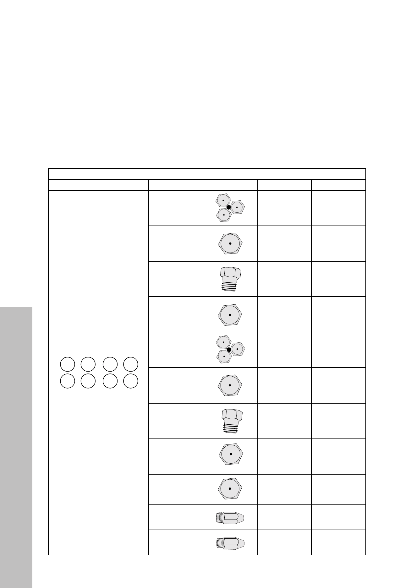
39
LIQUID PROPANE CONVERSION (CONTINUED)
IMPORTANT: The SGR48 series ranges have 8 cooktop burners, 2 of which are special
dual burners (A and E). These burners include 3 orifices to remove/replace — 1 in the
middle and 2 on the side.
SGR48 SERIES ORIFICES
BURNER LAYOUT BURNER PICTURE NG LPG
— 21 —
STEP 5 (Continued)
Gas Conversion
Changing Burner Nozzles
INSTALLATION TIP: To prevent any omissions,
remove ALL existing Natural Gas nozzles before
replacing them with the LP nozzles.
W diameter printed on the body. Install the proper
nozzles in the exact locations as noted in the
illustrations and table below (see Figure 15A, 15B or
15C).
Installation
1.16
0.9
1.16
0.9
LPGNG
1.36
1.79
1.79
1.36
Burner
B
C
D
A
D
C
B
A
Broil
Oven
0.941.42
1.42.13
0.89*2+0.53
0.74
0.9
NG
1.57
1.36*2+0.73
1.07
1.36
Burner
B
C
D
A
LPG
1.0
D
C
B
A
F
E
1.161.79E
0.91.36F
Broil
Oven
0.941.42
1.42.13
Débit d'entrée du bruleur (BTU/h) / Burner input rating
0.74
0.9
NG
1.57
1.36*2+0.73
1.07
1.36
Burner
B
C
D
A
1.0
0.89*2+0.53
LPG
D
C
B
A
F
E
H
G
Broil
Oven
0.941.42
1.42.13
0.74
0.9
1.57
1.36*2+0.73
1.07
1.36
F
G
H
E
1.0
0.89*2+0.53
18” Oven 1.091.68
30”
36”
48”
Figure 15C
53
89
116
100
90
74
1.09
1.4
0.94
53
89
116
100
90
74
1.09
1.4
0.94
53
89
116
100
90
1.09
1.4
0.94
53
89
100
90
1.4
0.94
53
89
100
90
1.4
0.94
53
89
116
100
90
74
1.09
1.4
0.94
53
89
116
100
90
74
0.94
53
89
116
100
90
74
1.09
1.4
0.94
53
89
100
90
1.4
0.94
53
89
100
90
1.4
0.94
Figure 15B
Figure 15A
53
89
116
100
90
74
1.09
1.4
0.94
53
89
100
90
1.4
0.94
53
89
116
100
90
74
1.09
1.4
0.94
53
89
100
90
1.4
0.94
53
89
116
53
89
116
100
90
74
53
89
116
100
90
53
89
100
90
1.4
0.94
53
89
116
100
90
74
0.94
53
89
116
100
90
74
1.09
1.4
0.94
53
89
100
90
1.4
0.94
53
89
53
89
100
90
53
89
100
90
53
100
0.94
53
89
116
100
90
74
0.94
53
100
0.94
53
89
116
100
90
74
1.09
1.4
0.94
53
89
116
100
90
74
1.09
1.4
0.94
53
89
100
90
1.4
0.94
53
89
116
100
90
74
1.09
1.4
0.94
A
B
C
D
B
C
D
AE
F
B
C
D
A
G
H F
E
A
— 21 —
STEP 5 (Continued)
Gas Conversion
Changing Burner Nozzles
INSTALLATION TIP: To prevent any omissions,
remove ALL existing Natural Gas nozzles before
replacing them with the LP nozzles.
W diameter printed on the body. Install the proper
nozzles in the exact locations as noted in the
illustrations and table below (see Figure 15A, 15B or
15C).
Installation
1.16
0.9
1.16
0.9
LPGNG
1.36
1.79
1.79
1.36
Burner
B
C
D
A
D
C
B
A
Broil
Oven
0.941.42
1.42.13
0.89*2+0.53
0.74
0.9
NG
1.57
1.36*2+0.73
1.07
1.36
Burner
B
C
D
A
LPG
1.0
D
C
B
A
F
E
1.161.79E
0.91.36F
Broil
Oven
0.941.42
1.42.13
Débit d'entrée du bruleur (BTU/h) / Burner input rating
0.74
0.9
NG
1.57
1.36*2+0.73
1.07
1.36
Burner
B
C
D
A
1.0
0.89*2+0.53
LPG
D
C
B
A
F
E
H
G
Broil
Oven
0.941.42
1.42.13
0.74
0.9
1.57
1.36*2+0.73
1.07
1.36
F
G
H
E
1.0
0.89*2+0.53
18” Oven 1.091.68
30”
36”
48”
Figure 15C
53
89
116
100
90
74
1.09
1.4
0.94
53
89
116
100
90
74
1.09
1.4
0.94
53
89
116
100
90
1.09
1.4
0.94
53
89
100
90
1.4
0.94
53
89
100
90
1.4
0.94
53
89
116
100
90
74
1.09
1.4
0.94
53
89
116
100
90
74
0.94
53
89
116
100
90
74
1.09
1.4
0.94
53
89
100
90
1.4
0.94
53
89
100
90
1.4
0.94
Figure 15B
Figure 15A
53
89
116
100
90
74
1.09
1.4
0.94
53
89
100
90
1.4
0.94
53
89
116
100
90
74
1.09
1.4
0.94
53
89
100
90
1.4
0.94
53
89
116
53
89
116
100
90
74
53
89
116
100
90
53
89
100
90
1.4
0.94
53
89
116
100
90
74
0.94
53
89
116
100
90
74
1.09
1.4
0.94
53
89
100
90
1.4
0.94
53
89
53
89
100
90
53
89
100
90
53
100
0.94
53
89
116
100
90
74
0.94
53
100
0.94
53
89
116
100
90
74
1.09
1.4
0.94
53
89
116
100
90
74
1.09
1.4
0.94
53
89
100
90
1.4
0.94
53
89
116
100
90
74
1.09
1.4
0.94
A
B
C
D
B
C
D
A
E
F
B
C
D
A
G
H F
E
1.36 (2) + 0.73 0.89 (2) + 0.53
B
— 21 —
STEP 5 (Continued)
Gas Conversion
Changing Burner Nozzles
INSTALLATION TIP: To prevent any omissions,
remove ALL existing Natural Gas nozzles before
replacing them with the LP nozzles.
W diameter printed on the body. Install the proper
nozzles in the exact locations as noted in the
illustrations and table below (see Figure 15A, 15B or
15C).
Installation
1.16
0.9
1.16
0.9
LPGNG
1.36
1.79
1.79
1.36
Burner
B
C
D
A
D
C
B
A
Broil
Oven
0.941.42
1.42.13
0.89*2+0.53
0.74
0.9
NG
1.57
1.36*2+0.73
1.07
1.36
Burner
B
C
D
A
LPG
1.0
D
C
B
A
F
E
1.161.79E
0.91.36F
Broil
Oven
0.941.42
1.42.13
Débit d'entrée du bruleur (BTU/h) / Burner input rating
0.74
0.9
NG
1.57
1.36*2+0.73
1.07
1.36
Burner
B
C
D
A
1.0
0.89*2+0.53
LPG
D
C
B
A
F
E
H
G
Broil
Oven
0.941.42
1.42.13
0.74
0.9
1.57
1.36*2+0.73
1.07
1.36
F
G
H
E
1.0
0.89*2+0.53
18” Oven 1.091.68
30”
36”
48”
Figure 15C
53
89
116
100
90
74
1.09
1.4
0.94
53
89
116
100
90
74
1.09
1.4
0.94
53
89
116
100
90
1.09
1.4
0.94
53
89
100
90
1.4
0.94
53
89
100
90
1.4
0.94
53
89
116
100
90
74
1.09
1.4
0.94
53
89
116
100
90
74
0.94
53
89
116
100
90
74
1.09
1.4
0.94
53
89
100
90
1.4
0.94
53
89
100
90
1.4
0.94
Figure 15B
Figure 15A
53
89
116
100
90
74
1.09
1.4
0.94
53
89
100
90
1.4
0.94
53
89
116
100
90
74
1.09
1.4
0.94
53
89
100
90
1.4
0.94
53
89
116
53
89
116
100
90
74
53
89
116
100
90
53
89
100
90
1.4
0.94
53
89
116
100
90
74
0.94
53
89
116
100
90
74
1.09
1.4
0.94
53
89
100
90
1.4
0.94
53
89
53
89
100
90
53
89
100
90
53
100
0.94
53
89
116
100
90
74
0.94
53
100
0.94
53
89
116
100
90
74
1.09
1.4
0.94
53
89
116
100
90
74
1.09
1.4
0.94
53
89
100
90
1.4
0.94
53
89
116
100
90
74
1.09
1.4
0.94
A
B
C
D
B
C
D
AE
F
B
C
D
A
G
H F
E
1.57 1.00
C
— 21 —
STEP 5 (Continued)
Gas Conversion
Changing Burner Nozzles
INSTALLATION TIP: To prevent any omissions,
remove ALL existing Natural Gas nozzles before
replacing them with the LP nozzles.
W diameter printed on the body. Install the proper
nozzles in the exact locations as noted in the
illustrations and table below (see Figure 15A, 15B or
15C).
Installation
1.16
0.9
1.16
0.9
LPGNG
1.36
1.79
1.79
1.36
Burner
B
C
D
A
D
C
B
A
Broil
Oven
0.941.42
1.42.13
0.89*2+0.53
0.74
0.9
NG
1.57
1.36*2+0.73
1.07
1.36
Burner
B
C
D
A
LPG
1.0
D
C
B
A
F
E
1.161.79E
0.91.36F
Broil
Oven
0.941.42
1.42.13
Débit d'entrée du bruleur (BTU/h) / Burner input rating
0.74
0.9
NG
1.57
1.36*2+0.73
1.07
1.36
Burner
B
C
D
A
1.0
0.89*2+0.53
LPG
D
C
B
A
F
E
H
G
Broil
Oven
0.941.42
1.42.13
0.74
0.9
1.57
1.36*2+0.73
1.07
1.36
F
G
H
E
1.0
0.89*2+0.53
18” Oven 1.091.68
30”
36”
48”
Figure 15C
53
89
116
100
90
74
1.09
1.4
0.94
53
89
116
100
90
74
1.09
1.4
0.94
53
89
116
100
90
1.09
1.4
0.94
53
89
100
90
1.4
0.94
53
89
100
90
1.4
0.94
53
89
116
100
90
74
1.09
1.4
0.94
53
89
116
100
90
74
0.94
53
89
116
100
90
74
1.09
1.4
0.94
53
89
100
90
1.4
0.94
53
89
100
90
1.4
0.94
Figure 15B
Figure 15A
53
89
116
100
90
74
1.09
1.4
0.94
53
89
100
90
1.4
0.94
53
89
116
100
90
74
1.09
1.4
0.94
53
89
100
90
1.4
0.94
53
89
116
53
89
116
100
90
74
53
89
116
100
90
53
89
100
90
1.4
0.94
53
89
116
100
90
74
0.94
53
89
116
100
90
74
1.09
1.4
0.94
53
89
100
90
1.4
0.94
53
89
53
89
100
90
53
89
100
90
53
100
0.94
53
89
116
100
90
74
0.94
53
100
0.94
53
89
116
100
90
74
1.09
1.4
0.94
53
89
116
100
90
74
1.09
1.4
0.94
53
89
100
90
1.4
0.94
53
89
116
100
90
74
1.09
1.4
0.94
A
B
C
D
B
C
D
AE
F
B
C
D
A
G
H F
E
1.07 0.74
D
— 21 —
STEP 5 (Continued)
Gas Conversion
Changing Burner Nozzles
INSTALLATION TIP: To prevent any omissions,
remove ALL existing Natural Gas nozzles before
replacing them with the LP nozzles.
W diameter printed on the body. Install the proper
nozzles in the exact locations as noted in the
illustrations and table below (see Figure 15A, 15B or
15C).
Installation
1.16
0.9
1.16
0.9
LPGNG
1.36
1.79
1.79
1.36
Burner
B
C
D
A
D
C
B
A
Broil
Oven
0.941.42
1.42.13
0.89*2+0.53
0.74
0.9
NG
1.57
1.36*2+0.73
1.07
1.36
Burner
B
C
D
A
LPG
1.0
D
C
B
A
F
E
1.161.79E
0.91.36F
Broil
Oven
0.941.42
1.42.13
Débit d'entrée du bruleur (BTU/h) / Burner input rating
0.74
0.9
NG
1.57
1.36*2+0.73
1.07
1.36
Burner
B
C
D
A
1.0
0.89*2+0.53
LPG
D
C
B
A
F
E
H
G
Broil
Oven
0.941.42
1.42.13
0.74
0.9
1.57
1.36*2+0.73
1.07
1.36
F
G
H
E
1.0
0.89*2+0.53
18” Oven 1.091.68
30”
36”
48”
Figure 15C
53
89
116
100
90
74
1.09
1.4
0.94
53
89
116
100
90
74
1.09
1.4
0.94
53
89
116
100
90
1.09
1.4
0.94
53
89
100
90
1.4
0.94
53
89
100
90
1.4
0.94
53
89
116
100
90
74
1.09
1.4
0.94
53
89
116
100
90
74
0.94
53
89
116
100
90
74
1.09
1.4
0.94
53
89
100
90
1.4
0.94
53
89
100
90
1.4
0.94
Figure 15B
Figure 15A
53
89
116
100
90
74
1.09
1.4
0.94
53
89
100
90
1.4
0.94
53
89
116
100
90
74
1.09
1.4
0.94
53
89
100
90
1.4
0.94
53
89
116
53
89
116
100
90
74
53
89
116
100
90
53
89
100
90
1.4
0.94
53
89
116
100
90
74
0.94
53
89
116
100
90
74
1.09
1.4
0.94
53
89
100
90
1.4
0.94
53
89
53
89
100
90
53
89
100
90
53
100
0.94
53
89
116
100
90
74
0.94
53
100
0.94
53
89
116
100
90
74
1.09
1.4
0.94
53
89
116
100
90
74
1.09
1.4
0.94
53
89
100
90
1.4
0.94
53
89
116
100
90
74
1.09
1.4
0.94
A
B
C
D
B
C
D
AE
F
B
C
D
A
G
H F
E
1.36 0.90
E
— 21 —
STEP 5 (Continued)
Gas Conversion
Changing Burner Nozzles
INSTALLATION TIP: To prevent any omissions,
remove ALL existing Natural Gas nozzles before
replacing them with the LP nozzles.
W diameter printed on the body. Install the proper
nozzles in the exact locations as noted in the
illustrations and table below (see Figure 15A, 15B or
15C).
Installation
1.16
0.9
1.16
0.9
LPGNG
1.36
1.79
1.79
1.36
Burner
B
C
D
A
D
C
B
A
Broil
Oven
0.941.42
1.42.13
0.89*2+0.53
0.74
0.9
NG
1.57
1.36*2+0.73
1.07
1.36
Burner
B
C
D
A
LPG
1.0
D
C
B
A
F
E
1.161.79E
0.91.36F
Broil
Oven
0.941.42
1.42.13
Débit d'entrée du bruleur (BTU/h) / Burner input rating
0.74
0.9
NG
1.57
1.36*2+0.73
1.07
1.36
Burner
B
C
D
A
1.0
0.89*2+0.53
LPG
D
C
B
A
F
E
H
G
Broil
Oven
0.941.42
1.42.13
0.74
0.9
1.57
1.36*2+0.73
1.07
1.36
F
G
H
E
1.0
0.89*2+0.53
18” Oven 1.091.68
30”
36”
48”
Figure 15C
53
89
116
100
90
74
1.09
1.4
0.94
53
89
116
100
90
74
1.09
1.4
0.94
53
89
116
100
90
1.09
1.4
0.94
53
89
100
90
1.4
0.94
53
89
100
90
1.4
0.94
53
89
116
100
90
74
1.09
1.4
0.94
53
89
116
100
90
74
0.94
53
89
116
100
90
74
1.09
1.4
0.94
53
89
100
90
1.4
0.94
53
89
100
90
1.4
0.94
Figure 15B
Figure 15A
53
89
116
100
90
74
1.09
1.4
0.94
53
89
100
90
1.4
0.94
53
89
116
100
90
74
1.09
1.4
0.94
53
89
100
90
1.4
0.94
53
89
116
53
89
116
100
90
74
53
89
116
100
90
53
89
100
90
1.4
0.94
53
89
116
100
90
74
0.94
53
89
116
100
90
74
1.09
1.4
0.94
53
89
100
90
1.4
0.94
53
89
53
89
100
90
53
89
100
90
53
100
0.94
53
89
116
100
90
74
0.94
53
100
0.94
53
89
116
100
90
74
1.09
1.4
0.94
53
89
116
100
90
74
1.09
1.4
0.94
53
89
100
90
1.4
0.94
53
89
116
100
90
74
1.09
1.4
0.94
A
B
C
D
B
C
D
AE
F
B
C
D
A
G
H F
E
1.36 (2) + 0.73 0.89 (2) + 0.53
F
— 21 —
STEP 5 (Continued)
Gas Conversion
Changing Burner Nozzles
INSTALLATION TIP: To prevent any omissions,
remove ALL existing Natural Gas nozzles before
replacing them with the LP nozzles.
W diameter printed on the body. Install the proper
nozzles in the exact locations as noted in the
illustrations and table below (see Figure 15A, 15B or
15C).
Installation
1.16
0.9
1.16
0.9
LPGNG
1.36
1.79
1.79
1.36
Burner
B
C
D
A
D
C
B
A
Broil
Oven
0.941.42
1.42.13
0.89*2+0.53
0.74
0.9
NG
1.57
1.36*2+0.73
1.07
1.36
Burner
B
C
D
A
LPG
1.0
D
C
B
A
F
E
1.161.79E
0.91.36F
Broil
Oven
0.941.42
1.42.13
Débit d'entrée du bruleur (BTU/h) / Burner input rating
0.74
0.9
NG
1.57
1.36*2+0.73
1.07
1.36
Burner
B
C
D
A
1.0
0.89*2+0.53
LPG
D
C
B
A
F
E
H
G
Broil
Oven
0.941.42
1.42.13
0.74
0.9
1.57
1.36*2+0.73
1.07
1.36
F
G
H
E
1.0
0.89*2+0.53
18” Oven 1.091.68
30”
36”
48”
Figure 15C
53
89
116
100
90
74
1.09
1.4
0.94
53
89
116
100
90
74
1.09
1.4
0.94
53
89
116
100
90
1.09
1.4
0.94
53
89
100
90
1.4
0.94
53
89
100
90
1.4
0.94
53
89
116
100
90
74
1.09
1.4
0.94
53
89
116
100
90
74
0.94
53
89
116
100
90
74
1.09
1.4
0.94
53
89
100
90
1.4
0.94
53
89
100
90
1.4
0.94
Figure 15B
Figure 15A
53
89
116
100
90
74
1.09
1.4
0.94
53
89
100
90
1.4
0.94
53
89
116
100
90
74
1.09
1.4
0.94
53
89
100
90
1.4
0.94
53
89
116
53
89
116
100
90
74
53
89
116
100
90
53
89
100
90
1.4
0.94
53
89
116
100
90
74
0.94
53
89
116
100
90
74
1.09
1.4
0.94
53
89
100
90
1.4
0.94
53
89
53
89
100
90
53
89
100
90
53
100
0.94
53
89
116
100
90
74
0.94
53
100
0.94
53
89
116
100
90
74
1.09
1.4
0.94
53
89
116
100
90
74
1.09
1.4
0.94
53
89
100
90
1.4
0.94
53
89
116
100
90
74
1.09
1.4
0.94
A
B
C
D
B
C
D
AE
F
B
C
D
A
G
H
F
E
1.57 1.00
G
— 21 —
STEP 5 (Continued)
Gas Conversion
Changing Burner Nozzles
INSTALLATION TIP: To prevent any omissions,
remove ALL existing Natural Gas nozzles before
replacing them with the LP nozzles.
W diameter printed on the body. Install the proper
nozzles in the exact locations as noted in the
illustrations and table below (see Figure 15A, 15B or
15C).
Installation
1.16
0.9
1.16
0.9
LPGNG
1.36
1.79
1.79
1.36
Burner
B
C
D
A
D
C
B
A
Broil
Oven
0.941.42
1.42.13
0.89*2+0.53
0.74
0.9
NG
1.57
1.36*2+0.73
1.07
1.36
Burner
B
C
D
A
LPG
1.0
D
C
B
A
F
E
1.161.79E
0.91.36F
Broil
Oven
0.941.42
1.42.13
Débit d'entrée du bruleur (BTU/h) / Burner input rating
0.74
0.9
NG
1.57
1.36*2+0.73
1.07
1.36
Burner
B
C
D
A
1.0
0.89*2+0.53
LPG
D
C
B
A
F
E
H
G
Broil
Oven
0.941.42
1.42.13
0.74
0.9
1.57
1.36*2+0.73
1.07
1.36
F
G
H
E
1.0
0.89*2+0.53
18” Oven 1.091.68
30”
36”
48”
Figure 15C
53
89
116
100
90
74
1.09
1.4
0.94
53
89
116
100
90
74
1.09
1.4
0.94
53
89
116
100
90
1.09
1.4
0.94
53
89
100
90
1.4
0.94
53
89
100
90
1.4
0.94
53
89
116
100
90
74
1.09
1.4
0.94
53
89
116
100
90
74
0.94
53
89
116
100
90
74
1.09
1.4
0.94
53
89
100
90
1.4
0.94
53
89
100
90
1.4
0.94
Figure 15B
Figure 15A
53
89
116
100
90
74
1.09
1.4
0.94
53
89
100
90
1.4
0.94
53
89
116
100
90
74
1.09
1.4
0.94
53
89
100
90
1.4
0.94
53
89
116
53
89
116
100
90
74
53
89
116
100
90
53
89
100
90
1.4
0.94
53
89
116
100
90
74
0.94
53
89
116
100
90
74
1.09
1.4
0.94
53
89
100
90
1.4
0.94
53
89
53
89
100
90
53
89
100
90
53
100
0.94
53
89
116
100
90
74
0.94
53
100
0.94
53
89
116
100
90
74
1.09
1.4
0.94
53
89
116
100
90
74
1.09
1.4
0.94
53
89
100
90
1.4
0.94
53
89
116
100
90
74
1.09
1.4
0.94
A
B
C
D
B
C
D
AE
F
B
C
D
A
G
H F
E
1.07 0.74
H
— 21 —
STEP 5 (Continued)
Gas Conversion
Changing Burner Nozzles
INSTALLATION TIP: To prevent any omissions,
remove ALL existing Natural Gas nozzles before
replacing them with the LP nozzles.
W diameter printed on the body. Install the proper
nozzles in the exact locations as noted in the
illustrations and table below (see Figure 15A, 15B or
15C).
Installation
1.16
0.9
1.16
0.9
LPGNG
1.36
1.79
1.79
1.36
Burner
B
C
D
A
D
C
B
A
Broil
Oven
0.941.42
1.42.13
0.89*2+0.53
0.74
0.9
NG
1.57
1.36*2+0.73
1.07
1.36
Burner
B
C
D
A
LPG
1.0
D
C
B
A
F
E
1.161.79E
0.91.36F
Broil
Oven
0.941.42
1.42.13
Débit d'entrée du bruleur (BTU/h) / Burner input rating
0.74
0.9
NG
1.57
1.36*2+0.73
1.07
1.36
Burner
B
C
D
A
1.0
0.89*2+0.53
LPG
D
C
B
A
F
E
H
G
Broil
Oven
0.941.42
1.42.13
0.74
0.9
1.57
1.36*2+0.73
1.07
1.36
F
G
H
E
1.0
0.89*2+0.53
18” Oven 1.091.68
30”
36”
48”
Figure 15C
53
89
116
100
90
74
1.09
1.4
0.94
53
89
116
100
90
74
1.09
1.4
0.94
53
89
116
100
90
1.09
1.4
0.94
53
89
100
90
1.4
0.94
53
89
100
90
1.4
0.94
53
89
116
100
90
74
1.09
1.4
0.94
53
89
116
100
90
74
0.94
53
89
116
100
90
74
1.09
1.4
0.94
53
89
100
90
1.4
0.94
53
89
100
90
1.4
0.94
Figure 15B
Figure 15A
53
89
116
100
90
74
1.09
1.4
0.94
53
89
100
90
1.4
0.94
53
89
116
100
90
74
1.09
1.4
0.94
53
89
100
90
1.4
0.94
53
89
116
53
89
116
100
90
74
53
89
116
100
90
53
89
100
90
1.4
0.94
53
89
116
100
90
74
0.94
53
89
116
100
90
74
1.09
1.4
0.94
53
89
100
90
1.4
0.94
53
89
53
89
100
90
53
89
100
90
53
100
0.94
53
89
116
100
90
74
0.94
53
100
0.94
53
89
116
100
90
74
1.09
1.4
0.94
53
89
116
100
90
74
1.09
1.4
0.94
53
89
100
90
1.4
0.94
53
89
116
100
90
74
1.09
1.4
0.94
A
B
C
D
B
C
D
AE
F
B
C
D
A
G
H
F
E
1.36 0.90
OVEN BROIL
— 21 —
STEP 5 (Continued)
Gas Conversion
Changing Burner Nozzles
INSTALLATION TIP: To prevent any omissions,
remove ALL existing Natural Gas nozzles before
replacing them with the LP nozzles.
W diameter printed on the body. Install the proper
nozzles in the exact locations as noted in the
illustrations and table below (see Figure 15A, 15B or
15C).
Installation
1.16
0.9
1.16
0.9
LPGNG
1.36
1.79
1.79
1.36
Burner
B
C
D
A
D
C
B
A
Broil
Oven
0.941.42
1.42.13
0.89*2+0.53
0.74
0.9
NG
1.57
1.36*2+0.73
1.07
1.36
Burner
B
C
D
A
LPG
1.0
D
C
B
A
F
E
1.161.79E
0.91.36F
Broil
Oven
0.941.42
1.42.13
Débit d'entrée du bruleur (BTU/h) / Burner input rating
0.74
0.9
NG
1.57
1.36*2+0.73
1.07
1.36
Burner
B
C
D
A
1.0
0.89*2+0.53
LPG
D
C
B
A
F
E
H
G
Broil
Oven
0.941.42
1.42.13
0.74
0.9
1.57
1.36*2+0.73
1.07
1.36
F
G
H
E
1.0
0.89*2+0.53
18” Oven 1.091.68
30”
36”
48”
Figure 15C
53
89
116
100
90
74
1.09
1.4
0.94
53
89
116
100
90
74
1.09
1.4
0.94
53
89
116
100
90
1.09
1.4
0.94
53
89
100
90
1.4
0.94
53
89
100
90
1.4
0.94
53
89
116
100
90
74
1.09
1.4
0.94
53
89
116
100
90
74
0.94
53
89
116
100
90
74
1.09
1.4
0.94
53
89
100
90
1.4
0.94
53
89
100
90
1.4
0.94
Figure 15B
Figure 15A
53
89
116
100
90
74
1.09
1.4
0.94
53
89
100
90
1.4
0.94
53
89
116
100
90
74
1.09
1.4
0.94
53
89
100
90
1.4
0.94
53
89
116
53
89
116
100
90
74
53
89
116
100
90
53
89
100
90
1.4
0.94
53
89
116
100
90
74
0.94
53
89
116
100
90
74
1.09
1.4
0.94
53
89
100
90
1.4
0.94
53
89
53
89
100
90
53
89
100
90
53
100
0.94
53
89
116
100
90
74
0.94
53
100
0.94
53
89
116
100
90
74
1.09
1.4
0.94
53
89
116
100
90
74
1.09
1.4
0.94
53
89
100
90
1.4
0.94
53
89
116
100
90
74
1.09
1.4
0.94
A
B
C
D
B
C
D
AE
F
B
C
D
A
G
H F
E
1.42 0.94
OVEN BAKE
— 21 —
STEP 5 (Continued)
Gas Conversion
Changing Burner Nozzles
INSTALLATION TIP: To prevent any omissions,
remove ALL existing Natural Gas nozzles before
replacing them with the LP nozzles.
W diameter printed on the body. Install the proper
nozzles in the exact locations as noted in the
illustrations and table below (see Figure 15A, 15B or
15C).
Installation
1.16
0.9
1.16
0.9
LPGNG
1.36
1.79
1.79
1.36
Burner
B
C
D
A
D
C
B
A
Broil
Oven
0.941.42
1.42.13
0.89*2+0.53
0.74
0.9
NG
1.57
1.36*2+0.73
1.07
1.36
Burner
B
C
D
A
LPG
1.0
D
C
B
A
F
E
1.161.79E
0.91.36F
Broil
Oven
0.941.42
1.42.13
Débit d'entrée du bruleur (BTU/h) / Burner input rating
0.74
0.9
NG
1.57
1.36*2+0.73
1.07
1.36
Burner
B
C
D
A
1.0
0.89*2+0.53
LPG
D
C
B
A
F
E
H
G
Broil
Oven
0.941.42
1.42.13
0.74
0.9
1.57
1.36*2+0.73
1.07
1.36
F
G
H
E
1.0
0.89*2+0.53
18” Oven 1.091.68
30”
36”
48”
Figure 15C
53
89
116
100
90
74
1.09
1.4
0.94
53
89
116
100
90
74
1.09
1.4
0.94
53
89
116
100
90
1.09
1.4
0.94
53
89
100
90
1.4
0.94
53
89
100
90
1.4
0.94
53
89
116
100
90
74
1.09
1.4
0.94
53
89
116
100
90
74
0.94
53
89
116
100
90
74
1.09
1.4
0.94
53
89
100
90
1.4
0.94
53
89
100
90
1.4
0.94
Figure 15B
Figure 15A
53
89
116
100
90
74
1.09
1.4
0.94
53
89
100
90
1.4
0.94
53
89
116
100
90
74
1.09
1.4
0.94
53
89
100
90
1.4
0.94
53
89
116
53
89
116
100
90
74
53
89
116
100
90
53
89
100
90
1.4
0.94
53
89
116
100
90
74
0.94
53
89
116
100
90
74
1.09
1.4
0.94
53
89
100
90
1.4
0.94
53
89
53
89
100
90
53
89
100
90
53
100
0.94
53
89
116
100
90
74
0.94
53
100
0.94
53
89
116
100
90
74
1.09
1.4
0.94
53
89
116
100
90
74
1.09
1.4
0.94
53
89
100
90
1.4
0.94
53
89
116
100
90
74
1.09
1.4
0.94
A
B
C
D
B
C
D
AE
F
B
C
D
A
G
H F
E
2.13 1.40
SMALL OVEN
— 21 —
STEP 5 (Continued)
Gas Conversion
Changing Burner Nozzles
INSTALLATION TIP: To prevent any omissions,
remove ALL existing Natural Gas nozzles before
replacing them with the LP nozzles.
W diameter printed on the body. Install the proper
nozzles in the exact locations as noted in the
illustrations and table below (see Figure 15A, 15B or
15C).
Installation
1.16
0.9
1.16
0.9
LPGNG
1.36
1.79
1.79
1.36
Burner
B
C
D
A
D
C
B
A
Broil
Oven
0.941.42
1.42.13
0.89*2+0.53
0.74
0.9
NG
1.57
1.36*2+0.73
1.07
1.36
Burner
B
C
D
A
LPG
1.0
D
C
B
A
F
E
1.161.79E
0.91.36F
Broil
Oven
0.941.42
1.42.13
Débit d'entrée du bruleur (BTU/h) / Burner input rating
0.74
0.9
NG
1.57
1.36*2+0.73
1.07
1.36
Burner
B
C
D
A
1.0
0.89*2+0.53
LPG
D
C
B
A
F
E
H
G
Broil
Oven
0.941.42
1.42.13
0.74
0.9
1.57
1.36*2+0.73
1.07
1.36
F
G
H
E
1.0
0.89*2+0.53
18” Oven 1.091.68
30”
36”
48”
Figure 15C
53
89
116
100
90
74
1.09
1.4
0.94
53
89
116
100
90
74
1.09
1.4
0.94
53
89
116
100
90
1.09
1.4
0.94
53
89
100
90
1.4
0.94
53
89
100
90
1.4
0.94
53
89
116
100
90
74
1.09
1.4
0.94
53
89
116
100
90
74
0.94
53
89
116
100
90
74
1.09
1.4
0.94
53
89
100
90
1.4
0.94
53
89
100
90
1.4
0.94
Figure 15B
Figure 15A
53
89
116
100
90
74
1.09
1.4
0.94
53
89
100
90
1.4
0.94
53
89
116
100
90
74
1.09
1.4
0.94
53
89
100
90
1.4
0.94
53
89
116
53
89
116
100
90
74
53
89
116
100
90
53
89
100
90
1.4
0.94
53
89
116
100
90
74
0.94
53
89
116
100
90
74
1.09
1.4
0.94
53
89
100
90
1.4
0.94
53
89
53
89
100
90
53
89
100
90
53
100
0.94
53
89
116
100
90
74
0.94
53
100
0.94
53
89
116
100
90
74
1.09
1.4
0.94
53
89
116
100
90
74
1.09
1.4
0.94
53
89
100
90
1.4
0.94
53
89
116
100
90
74
1.09
1.4
0.94
A
B
C
D
B
C
D
AE
F
B
C
D
A
G
H F
E
1.68 1.09
INSTALLATION
Liquid Propane Conversion
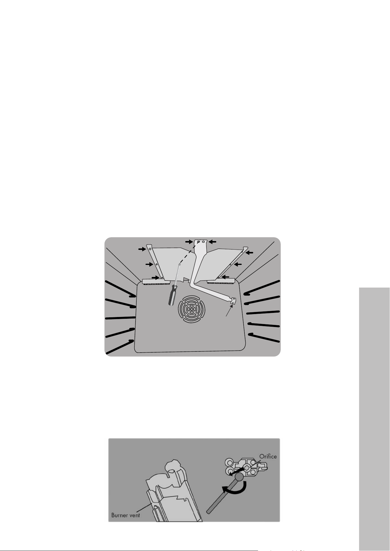
40
LIQUID PROPANE CONVERSION (CONTINUED)
CHANGING UPPER OVEN ORIFICES - SGR30, SGR36, SGR48 LARGE OVEN
1. Open the oven door and remove the racks. To do so, slide out the racks to their full
extensions, and then lift them up and out of the sliding mechanisms. Next, remove the
bottom drip pan by lifting up from each front corner and sliding out, using care to not
damage the lower burner spread in the process. Set aside.
2. Remove the upper broil burner spread screws (8 total — 2 at the front and 3 along
each side) with a Phillips-head drill bit or screwdriver, as shown in the figure below.
Carefully remove the burner vent from its connection against the back wall of the oven.
This provides access to the orifice.
Débit d'entrée du bruleur (BTU/h) / Burner input rating
— 22 —
STEP 5 (Continued)
Gas Conversion
Changing Oven Nozzles (ranges only)
X
Open the oven door and r emove the bottom drip
pan and sliding racks.
at
Remove the upper bur ner screw. Remove the burner
from its connection against the back wall of the oven
(see Figure 16). Be careful not to scratch or damage
the connection wire that will remain connected
throughout this procedure.
ak
Using a 10 mm socket wrench, remove the nozzle.
Set the natural gas nozzle aside and replace with the
liquid propane gas nozzle. Screw in and tighten the
new nozzle.
al
Place the burner vent back into position over the
new nozzle in the AR3 slot.
am
Secure the burner back in place with the mounting
screw that was removed in step 10.
an
Follow steps 10 through 13 with the bottom burner
(see Figure 18). Ensure the nozzles and burners are
secured properly. When finished, replace drip pan
and sliding racks.
Installation
Figure 16
Figure 17
AR3
Orifice
Burner vent
Figure 18
Orifice
location
3. Using a 7 mm socket wrench, remove the natural gas orifice as outlined in the figure
below; set it aside and replace with the liquid propane gas orifice. Screw in the new
orifice; use care to not overtighten. Place the burner vent back into position over the new
orifice as outlined in the figure below, then re-secure the burner spread with the screws
removed in step 2.
INSTALLATION
Liquid Propane Conversion
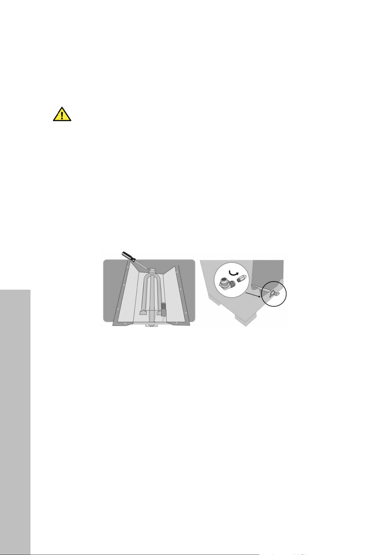
41
LIQUID PROPANE CONVERSION (CONTINUED)
WARNING
Be careful not to scratch or damage the connection wire that will remain
connected throughout this procedure for the upper burner spread.
CHANGING LOWER OVEN ORIFICES - SGR30, SGR36, SGR48 SMALL OVEN
1. For the lower burner spread, remove the 2 screws at the rear of the oven, as outlined in
the left image below. Carefully lift the burner up and back into the oven cavity to access
the orifice located at the front of the burner.
Using a 10 mm socket wrench, remove the natural gas orifice as outlined in the right
image below; set aside and replace with the liquid propane gas orifice. Place the burner
vent back into position before re-securing the 2 screws at the rear of the oven.
2. When finished, replace the bottom drip pan and the sliding racks in the reverse order in
which they were removed in step 1.
NOTES:
• The diagrams above detail the lower burner spreads for the SGR30 and SGR36 series
ranges, as well as that of the larger oven on the SGR48 model. For the SGR48 smaller
oven, the lower burner spread will look slightly different; however, the orifice swap
process in Step 4 remains the same.
• Since the SGR48 smaller oven doesn’t have an upper broil burner, no upper orifice
change is needed for liquid propane conversion.
• After completing the conversion procedure, be sure to check all piping connections in
the unit for leaks. Use a soap solution, 75% water, 25% dish soap. Make certain you
have checked them all, and repair any connections that leak.
INSTALLATION
Liquid Propane Conversion
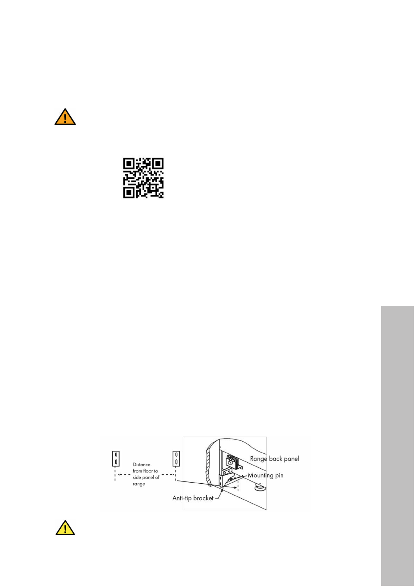
42
INSTALLATION
INSTALLING THE ANTI-TIP DEVICE
DANGER
A child or adult can tip the range and be seriously injured or killed. Do not
operate the range without the anti-tip device in place. Failure to follow these
instructions can result in death or serious burns to children and adults.
Scan to follow along with a video.
1. After determining the final installation location within your cabinet, raise or lower the
feet of the range to desired height and slide the range forward to access the back wall.
2. Secure each anti-tip bracket to the back wall by drilling 2 holes for each and fasten with
the 4 provided screws, making sure the mounting side of the bracket faces toward the
cabinet, as outlined in the right image below. For concrete or tile, tap 4 anchors into the
drilled holes with a hammer, then fasten the bracket with the provided screws.
3. To determine proper height for each bracket, measure from the floor to the bottom of
each side panel as outlined in the images below. Ensure both brackets are level.
4. Screw in the mounting pins provided with the anti-tip bracket kit into each side of the
range within the bottom oven recess at left and right.
5. For reference, the width of the SGR30 series ranges oven bottom recess is
28 1/4" (718 mm). Installing both brackets so the mounting side of the bracket faces
toward the cabinet should allow both to fit comfortably within that 28 1/4" (718 mm)
oven recess. For the SGR36 series ranges, the recess width is 34 1/4" (870 mm). For the
SGR48 series ranges, the recess width is 46 1/8" (1172 mm). However, cabinet cutouts
vary by kitchen, so be sure to carefully measure before securing the brackets.
6. Slide the range back toward the wall, then safely tilt the front of the range upward slightly
and move it back to its final resting place, making sure the mounting pin slides under
bracket, as outlined below.
WARNING
Carefully pull on the range from the rear. If the anti-tip device is installed
correctly, the mounting pin will make contact with the bracket and the range will
not tip more than 4" (102 mm) from the wall.
Installing the Anti-Tip Devices
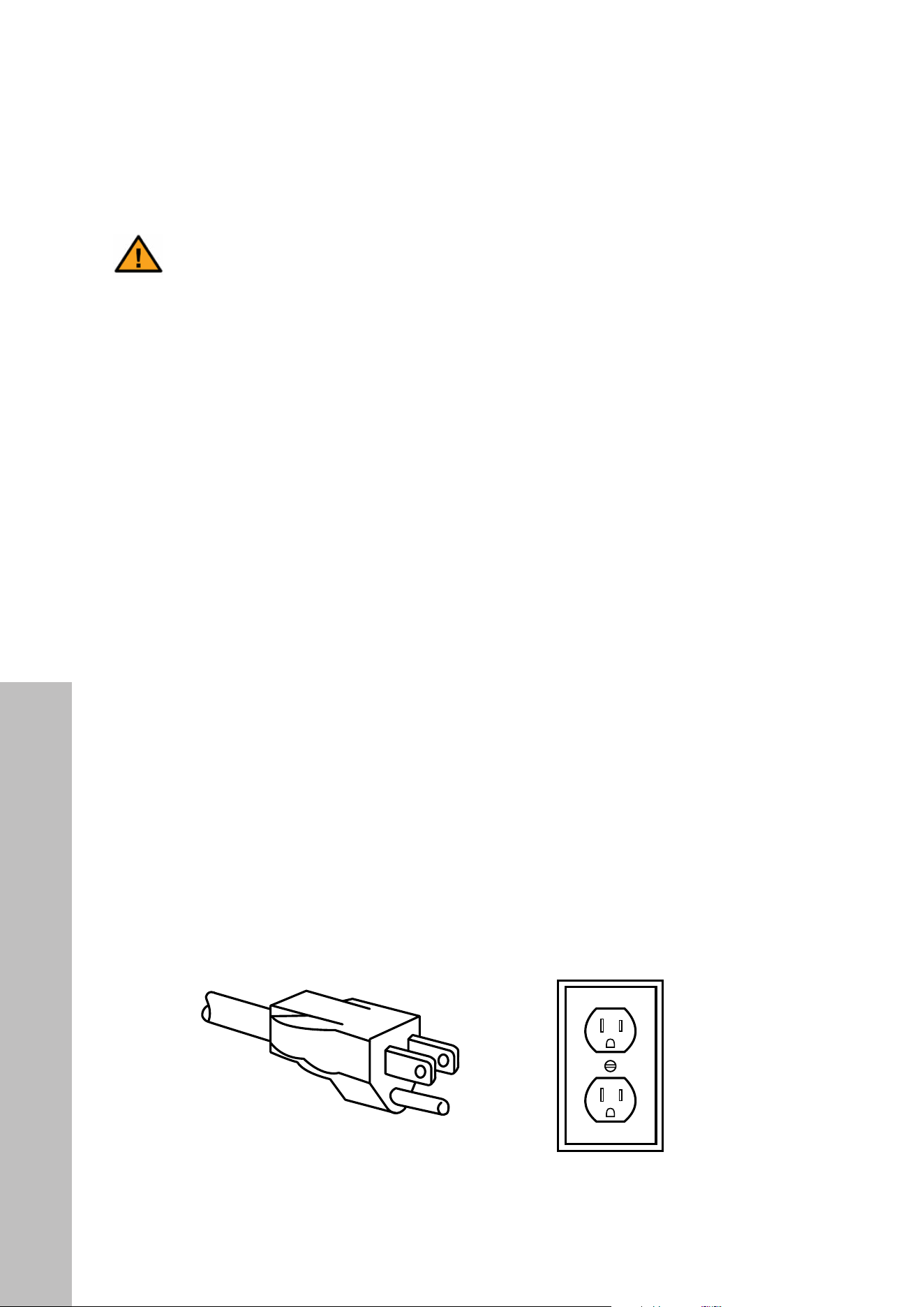
43
INSTALLATION
CONNECT TO POWER
DANGER
Electric Shock Hazard
• Please make sure to read ALL safety precautions on pages 1–15 and throughout
both the Installation Manual and User Manual.
• Do not use any sort of power adapter for this appliance.
• Do not use an extension cord for this appliance.
• Failure to follow these instructions can result in death, fire, or electrical shock.
• Any additions, changes, or conversions required to properly operate this appliance
must be made by a qualified service technician in accordance with the manufacturer’s
instructions and all codes and requirements of the local governing authority.
• The safety circuit-breaker and the electrical system must be able to withstand the load
of the appliance. See label on back of appliance should you need to verify any of the
electrical requirements.
• This appliance is 120VAC/60Hz. A dedicated circuit, protected by a minimum 15-amp
circuit breaker, is required for electrical connection.
• The power cord is equipped with a 3-prong NEMA 5-15P plug that mates with a standard
3-prong grounding wall receptacle to minimize the possibility of electrical shock hazard
from the appliance (see figure below).
• The appliance must be electrically grounded in accordance with local codes or, in the
absence of local codes, with the National Electrical Code, ANSI/NFPA 70. In Canada,
the appliance must be electrically grounded in accordance with Canadian Electrical Code.
grounding pin
3-prong receptacle3-prong plug
Connect to Power
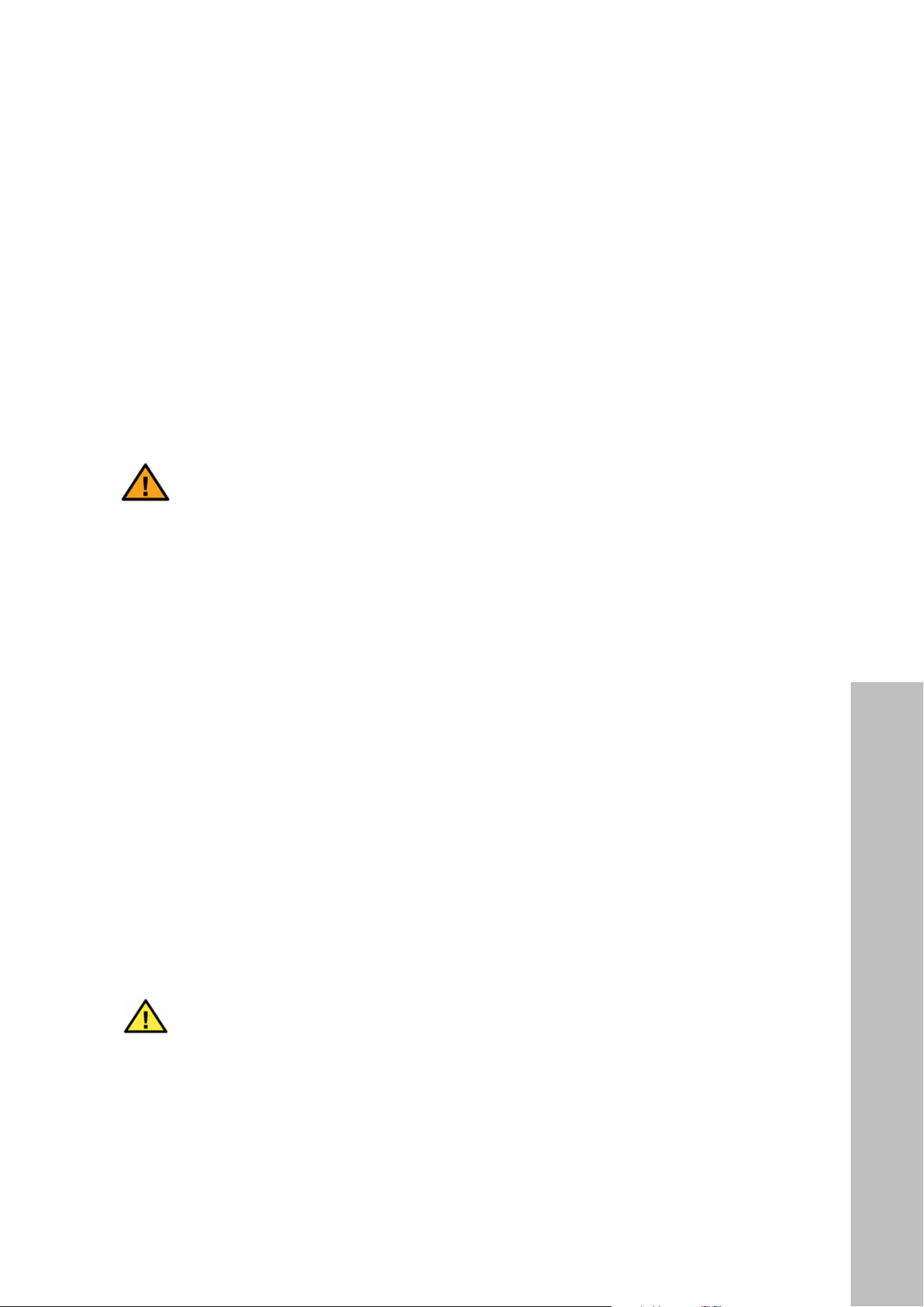
44
• The electrical socket must be easily accessible with the appliance installed. In all cases,
the power supply lead must be positioned so that it does not reach a temperature of
122 °F (50 °C) above the room temperature at any point.
• The manufacturer is not liable for any direct or indirect damage caused by faulty
installation or connection.
• Never use reductions, shunts, or adapters that can cause overheating or burning.
• Make sure the power supply cable does not come in contact with any parts or components
that get hot.
DANGER
Installers and users should disconnect the electrical supply whenever cleaning
or servicing the product to avoid risk of electric shock or injury.
FINISH INSTALLATION
1. After your gas connection and anti-tip brackets are properly installed, and the electrical
cord is plugged in, slide the range into place.
2. Check to make sure the range does not tip more than 4" (102 mm).
3. Install all burner spreads onto the cooktop by making sure the white sparks tips for each
burner fits into the hole in each burner spread.
4. Carefully place each burner cap onto each burner spread so it fits snug and is level.
5. Carefully place all grates onto the cooktop, being careful to not scratch the burner caps,
burner spreads, or porcelain cooktop.
6. Using a level, adjust the front and/or rear feet so the range frame is even with the
counter top and level or uneven baking may result.
7. When all connections have been made, check that all range controls are in the “off”
position and turn on the main gas supply valve.
WARNING
It may take a few minutes before gas will freely flow through the unit, so it could
take a few attempts to light the cooktop and/or oven. Refer to the User Manual
for how to operate cooktop burners and adjust flame settings.
NOTE: The installer should leave these instructions with the consumer who should retain for
local inspectors’ use and for future reference. Installers and consumers should refer to the
User Manual for additional safety measures, operation tips, and troubleshooting.
INSTALLATION
Connecting to Power

COVERAGE
ZLINE Kitchen and Bath range products will be warrantied for one year from the original
purchase date for the original purchaser of the product. This warranty covers all parts and
labor for necessary repairs if any part of the product proves to be defective in materials or
workmanship. The product must be deemed serviceable via troubleshooting with the ZLINE
Kitchen and Bath service team. All service on ZLINE Kitchen and Bath range products under
the above warranty must be performed by ZLINE approved and certified service providers,
unless otherwise specified by ZLINE Kitchen and Bath. Service will be provided during
normal business hours.
TERMS
This warranty applies only to the original purchaser of a range product installed for
normal residential use. This is defined as a single-family, residential dwelling in a non-
commercial setting. Commercial settings include but are not limited to: schools, churches,
hotels, restaurants, vacation rentals such as Airbnb, day care centers, private clubs, fire
stations, common areas in multi-family dwellings, nursing homes, food service locations,
and institutional food service locations such as hospitals or correction facilities. This warranty
is non-transferable and will not be extended based on the date of installation. The warranty
applies only to products installed in the contiguous United States and the District of Columbia.
Failure to secure certified warranty service per these terms will result in a forfeiture of the
remaining warranty. Out of pocket payments will not be reimbursed unless prior approval
is received from ZLINE Kitchen and Bath and/or our service contract partner. Unapproved
out of pocket payments for service will not be reimbursed. All warranty procedures must be
followed to maintain warranty coverage.
Warranty shall not apply and ZLINE Kitchen and Bath is not responsible for damage resulting
from negligence, improper maintenance, misuse, abuse, alteration of or tampering with the
appliance, accident, natural disaster, improper electric supply, flare-up fires, unauthorized
service or repair, improper installation, or installation not in accordance with the instructions
contained in the manual, or with local government codes.
WARRANTY

WHAT IS NOT COVERED
1. Installation or start-up, damages or problems caused by improper installation or use.
2. Improper liquid propane gas conversion or damage related to improper liquid propane
gas conversion.
3. Range top burner flame adjustments or related complaints.
4. Service by unauthorized service providers or damage related to unauthorized service
or unauthorized parts.
5. Installation in any commercial or non-residential application.
6. Corrections regarding normal adjustments or settings, or local gas supply issues resulting
in low gas pressure or other issues.
7. Removal or re-installation cost.
8. Aesthetic damage, scratches, or natural wear caused by normal use.
9. Second-hand, open box products, or products purchased from an unauthorized retailer.
10. Service for gas pressure issues related to installation at high altitudes. A high-altitude
pressure regulator must be sourced by the customer.
NOTE: In the event that service is dispatched, and it is discovered that the reported
issue is not covered under warranty based on the disclaimers above, the customer will
be responsible for all service fees. Failure to pay these fees will result in the forfeiture of
remaining warranty coverage.
WARRANTY
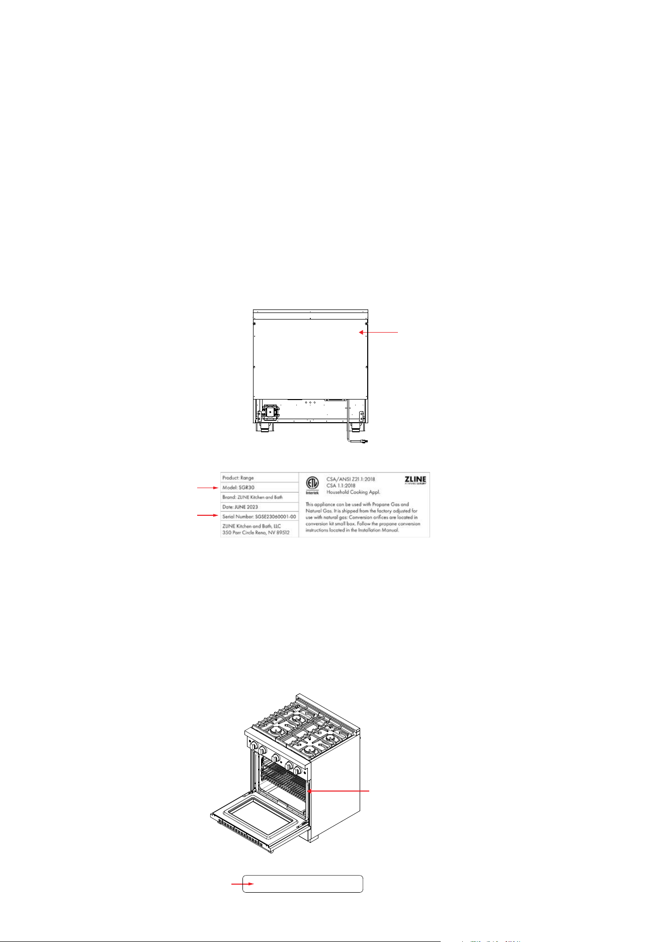
WARRANTY
SERIAL NUMBER LOCATIONS
SGR30 SERIES MODELS
The rating tag shows the model and serial number of your range. The tag is located on the
back of the range. On some SGR30 series models, the serial number may be on the right
front edge of the range; reference the section at bottom of page. Do not remove permanently
affixed labels, warnings, or plates from the product. This will void the warranty.
Appliance
Tag Here
36”
30”
Appliance Tag Here
SGR30, SGR36, AND SGR48 SERIES MODELS
The serial number tag shows the serial number of your range. The tag is located on the right
front edge of your range. The door must be open for the tag to be visible. Do not remove
permanently affixed labels, warnings, or plates from the product. This will void the warranty.
Serial Number
Tag Here
S/N: SGSE23060339-00

WARRANTY
SERVICE
For warranty service, please contact our Customer Service team at
1-614-777-5004 or visit www.zlinekitchen.com/contact to utilize our
online Customer Experience Portal.
Need to purchase a part or accessory for your ZLINE product?
Visit www.zlineparts.com, ZLINE’s official parts distribution partner.