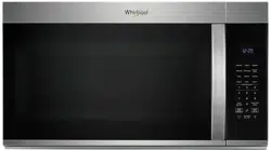
MICROWAVE OVEN HOOD COMBINATION OWNER’S MANUAL
Control Guide
WARNING: To reduce the risk of fire, electric shock, or injury to persons, read the IMPORTANT SAFETY INSTRUCTIONS, located in your appliance's Owner's Manual, before operating this appliance.
This manual covers several models. Your model may have some or all of the items listed. Refer to this manual or the Product Help section of our website at www.whirlpool.com/owners for more detailed instructions. In Canada, refer our website www.whirlpool.ca/owners. For more specific details on a feature and steps to use the features listed, refer to the titled section for that feature.
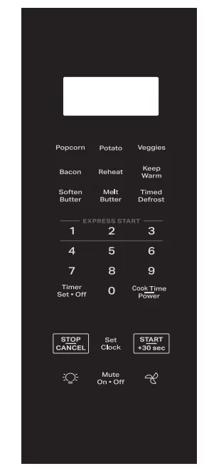
Control Panel
Icons on Display
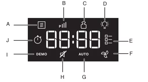
A. Cook
B. Power
C. Amount/weight
D. Light
E. Select food category
F. Fan
G. Auto
H. Mute
I. Demo
J. Kitchen timer
Electronic Oven Controls
| BUTTONS |
FEATURE |
INSTRUCTION |
 |
Turn on/off the hood fan |
Press the  button to adjust the hood fan setting among HI->LO->OFF. The hood fan function can be operated independently. button to adjust the hood fan setting among HI->LO->OFF. The hood fan function can be operated independently.
NOTE: To keep the microwave oven from overheating, the vent fan will automatically turn on if the temperature from the range or cooktop below the microwave oven gets too hot. When this occurs, the vent fan cannot be turned off. The "AUTO" icon and "Fan Icon" will turn on the display. |
| Mute On-Off |
Mute all system sounds |
Activate mute sounds:
Press the Mute On-Off button will mute all sounds, mute icon will be shown on the display.
Inactivate mute sounds:
Press the Mute On-Off button again will unmute all sounds, mute icon will disappear on the display. |
 |
Turn on/off hood light |
Press the  button to adjust the hood light setting among HI->LO->OFF. The hood light function can be operated independently. button to adjust the hood light setting among HI->LO->OFF. The hood light function can be operated independently. |
| START/+30 sec |
Cooking start |
The Start button begins any oven function. If cooking is interrupted by opening the door, pressing the Start button after the door is closed again will resume the preset cycle. |
| START/+30 sec |
Quick start for 30 seconds |
Use the +30 sec and 1, 2 and 3 minute express start buttons to quickly start a cycle or add time mid cycle.
See Express Cook section for details.
See the Manual Cooking section to change the cooking time or power level. |
| EXPRESS START "1" |
Quick start for 1 minute |
| EXPRESS START "2" |
Quick start for 2 minutes |
| EXPRESS START "3" |
Quick start for 3 minutes |
| Set Clock |
Set the clock |
This microwave uses a 12 hour clock (1:00 - 12:59). To set the clock, follow the instructions below:
1. Press the Set Clock button to set the clock.
2. Use the number buttons to set the clock.
3. Press the Set Clock button or wait 5 seconds will save. |
| STOP/CANCEL |
Stop or cancel cooking function |
During input
Pressing the STOP/CANCEL button once to clear the input.
Pressing the STOP/CANCEL button twice to exit input.
During cooking cycle
Pressing the STOP/CANCEL button once to pause the cycle.
Pressing the STOP/CANCEL button twice to stop/cancel cycle. |
| Cook Time/Power |
Set manual cooking time and power |
To set cooking time length and change power level:
1. Press the Cook Time/Power button.
2. Press the number buttons to set the length of cook time, for example 2:30, press number "2 3 0".
3. Press the Cook Time/Power button again to change the power level.
4. Press number buttons to set the power level, for example press "8 0" to set the power level to 80%.
5. Press the START button to start.
You can skip steps 3 and 4 if you want to cook at 100% power level. |
| Timer Set-Off |
Kitchen Timer |
For example to set 60 minutes timer.
1. Press the Timer Set-Off button.
2. Press the number buttons "6 0 0 0".
3. Press the Timer Set-Off button to start kitchen timer. |
| Popcorn |
Popcorn |
1. Press the Popcorn button.
2. Press the number buttons to enter food weight (refer to the cooking sticker on the product).
3. Press the Start button to cook. |
| Potato |
Potato |
1. Press the Potato button repeatedly to select potato size: 1 - Small potato 2 - Large potato
2. Press the number buttons to select food amounts/weight: Small potato: 4-16 potatoes Large potato: 1-4 potatoes
3. Press the Start button. |
| Veggies |
Vegetables |
1. Press the Veggies button repeatedly to select vegetable category: 1 - Canned Vegetables 2 - Fresh Vegetables 3 - Frozen Vegetables
2. Press the number buttons to select food amounts/weight (1-4 cups).
3. Press the Start button. |
| Bacon |
Bacon |
1. Press the Bacon button.
2. Press the number buttons to select food amounts/weight: 1-6 slice.
3. Press the Start button. |
| Reheat |
Reheat |
1. Press the Reheat button repeatedly to select category:
1 - Beverage
2 - Casserole
3 - Dinner Plate
4 - Soup/Sauce
5 - Baked Goods
6 - Pizza
7 - Manual Reheat
2. Press the number buttons to select food amounts/weight.
Beverage: 1-2 cups
Casserole: 1-4 cups
Dinner Plate: 1 plate
Soup/Sauce: 1-4 cups
Baked Goods: 1-6 pieces
Pizza: 1-3 slices
Manual Reheat: 70% power level, 0-90 minutes
3. Press the Start button.
|
| Keep Warm |
Keep Warm |
1. Press the Keep Warm button.
2. Press the number buttons to enter time 15, 30 (default), 45 or 60 minutes.
3. Press the Start button. |
| Soften Butter |
Soften Butter |
1. Press the Soften Butter button.
2. Press the number buttons to enter weight: 0.5, 1.0 (default), 1.5 or 2.0 sticks.
3. Press the Start button. |
| Melt Butter |
Melt Butter |
1. Press the Melt Butter button.
2. Press the number buttons to enter weight: 0.5, 1.0 (default), 1.5 or 2.0 sticks.
3. Press the Start button. |
| Timed Defrost |
Timed Defrost |
1. Press the Timed Defrost button repeatedly to select category:
1 - Ground Beef
2 - Chicken Breast
3 - Manual Defrost
2. Press the number buttons to select food amounts/weight:
Ground Beef: 0.2-6.6 lb
Chicken Breast: 0.2-6.6 lb
Manual Defrost: 20% power level, 0-90 minutes.
3. Press the Start button.
|
Microwave Oven Use
Odors and smoke are normal when the microwave oven is used the first few times or when it is heavily soiled.
IMPORTANT: The health of some birds is extremely sensitive to the fumes given off. Exposure to the fumes may result in death to certain birds. Always move birds to another closed and well ventilated room.
Electronic Oven Controls
Display
When power is first supplied to the microwave oven, 12:00 will appear in the display, press number buttons to set the clock. Press Set Clock button or wait few seconds to confirm.
A power failure has occurred or reset the clock if needed. See the "Clock" section.
Standby mode
When no functions are working (12-hour clock is displayed or if the clock has not been set), oven will switch to Standby Power mode and dim the display brightness. Press any button or open/close the door, and then display will return to the normal brightness.
Set Clock
The Clock is a 12-hour (1:00-11:59) without AM/PM. Press Set Clock button to set the clock.
- Press the Set Clock button.
- Press the number buttons to set Clock HH:MM.
- Press the Set Clock button, or wait for around 5 seconds will save.
If the clock set is not correctly, start the clock with the clock value in the memory. If not value is saved in memory, display will start with 12:00.
Mute On-Off
This function allows the user to activate/deactivate all the sounds played by the appliances, includes button press, warnings, alarm, even end audio feedback.
Activate mute sounds:
Press the Mute On-Off button will mute all sounds, mute it will be shown on the display.
Inactivate mute sounds:
Press the Mute On-Off button again will unmute all sounds, mute it will disappear on the display.
Demo Mode
Activate to practice using the control without actually turning on the magnetron or heating elements.
Activate:
Long press number button "3", "DEMO" icon lights up in the display.
Deactivate:
Long press number button "3", "DEMO" icon switched off in the display.
Timer Set-Off
You can set Kitchen Timer by pressing the Timer Set-Off button. For example to set 60 minutes timer.
- Press the Timer Set-Off button.
- Press the number buttons "6 0 0 0".
- Press the Timer Set-Off button to start kitchen timer.
NOTE: During kitchen timer counting down, press the Timer Set-Off button will cancel the timer. If you press the Timer Set-Off button when cooking is running:
1. Press the Timer Set-Off button once, the display will shown the kitchen timer screen.
2. Press the Timer Set-Off button again will cancel the timer.
Cooking General guide
- Please follow the function instructions to cook the different types of foods.
- For better cooking performance, it is recommended to stir/turn and let the food stand 1 minute after cooking and reheat.
- For better cooking performance, try to use the preset button first.
- For auto function, Auto functions never allow any change:
- You can start and proceed with remaining time after the door is shut and you press start.
Express Cook
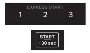
Use the +30 sec and 1, 2 and 3 minutes express start buttons to quickly start a cycle or add time mid cycle.
Start/+30 sec
Each press of the button "Start/+30 sec" will add 30 seconds more to the cooking time.
Express Start "1"
Each press of the button "1" will add 1 minute more to the cooking time.
Express Start "2"
Each press of the button "2" will add 2 minute more to the cooking time.
Express Start "3"
Each press of the button "3" will add 3 minute more to the cooking time.
NOTE: If you want to change the cooking time or power level, see the manual cooking section for details.
Cook Time/Power
Use the Cook Time/Power to set manual cooking. Place food in microwave-safe container.
For example to cook for 1 minute 45 seconds at 80% power level.
- Press the Cook Time/Power button once.
- Press the number buttons "1 4 5".
- Press the Cook Time/Power button again.
- Press the number buttons "8 0".
- Close the door.
- Pressing the Start button to start.
Power Level Table
| Percent/ Name |
Number |
Use |
| 100% |
100 |
Quick heating convenience foods and foods with high water content, such as cooking soups with raw ingredients, heating beverages, and cooking most vegetables. |
| 90% |
90 |
Cooking small, tender pieces of meat, ground meat, poultry pieces, and fish fillets. Heating cream soups. |
| 80% |
80 |
Heating rice, pasta, or casseroles. Cooking and heating foods that need a cook power lower than high, for example, whole fish and meat loaf. |
| 70% |
70 |
Reheating ready-cooked food, single or multiple dishes. |
| 60% |
60 |
Cooking sensitive foods such as cheese and egg dishes, pudding, and custards. |
| 50% |
50 |
Cooking non-stirrable casseroles, such as lasagna. |
| 40% |
40 |
Cooking ham, whole poultry, and pot roasts. |
| 30% |
30 |
Simmering stews, melting butter. |
| 20% |
20 |
Defrosting, melting chocolate. Heating bread, rolls, and pastries. |
| 10% |
10 |
Taking chill out of fruit, Softening butter, cheese, and ice cream. |
Tips and suggestions:
For a better cooking performance, it is recommended to stir/turn and let the food stand 1 minutes after cooking and reheat.
Popcorn
Enter 3.0 or 3.5 oz (85 or 99 g)
- Do not use regular paper bags or glassware. Follow manufacturer's instructions when using a microwave popcorn popper.
- Listen for popping to slow to one pop every 1 or 2 seconds, and then stop the cycle. Do not repop unpopped kernels.
- For best results, use fresh bags of popcorn.
- Cooking results may vary by brand and fat content. Follow the instructions provided by the microwave popcorn manufacturer.
1. Press the Popcorn button.
2. Press the number buttons to enter food weight 3 0 or 3 5.
3. Press the Start button to cook.
Potato
- Press the Potato button continuously, to select food, 1- Small Potato, 2- Large Potato, wait a second to confirm.
- Press the number button to select potato quantity (see below chart).
- Close the door.
- Press the Start button to cook.
| Item |
Food Category |
Quantity |
Instruction |
| 1 |
Small potato |
4-16 potatoes, 3-5 oz (85-141 g) each |
■ Pierce each potato 2-3 times with a fork.
■ Place on paper towel, around turntable edges.
■ Let stand for 5 minutes after cooking. |
| 2 |
Large potatoes |
1-4 potatoes, 8-10 oz (227-283 g) each |
■ Pierce each potato several times with a fork.
■ Place on paper towel, around turntable edges.
■ Place single potato to the side of the turntable.
■ Let stand for 5 minutes after cooking. |
Veggies
- Press the Veggies button continuously, to select option (see below chart).
- Press the number button to select food quantity (see below chart).
- Close the door.
- Press the Start button to cook.
| Item |
Food Category |
Quantity |
Instruction |
| 1 |
Canned Vegetables |
1-4 cups |
■ Place in microwave-safe container.
■ Cover with plastic wrap and vent. Stir and let stand 3 minutes after cooking. |
| 2 |
Fresh Vegetables |
1-4 cups |
■ Place in microwave-safe container and add 2-4 tablespoon water.
■ Cover with plastic wrap and vent. Stir and let stand 3 minutes after cooking. |
| 3 |
Frozen Vegetables |
1-4 cups |
Bacon
- Press the Bacon button.
- Press the number buttons to select quantity 1-6 slices (2 is default).
- Close the door.
- Press the Start button to cook.
Cooking Tips:
Average thickness: Follow directions on package. For best results, place bacon on microwave-safe bacon rack.
Reheat
Times and cooking powers have been preset for reheating a number of food types. Use the following chart as a guide.
- Press Reheat button continuously, to select option (see below chart).
- Use number buttons to select food quantity (see below chart).
- Close the door.
- Press the Start button to cook.
| Item |
Food Category |
Quantity |
Instruction |
| 1 |
Beverage |
1-2 cups |
Do not cover. |
| 2 |
Casserole |
1-4 cups (220-880 g) |
Place in a microwave-safe container. Cover with plastic wrap and vent. Stir and let stand for 3 minutes after reheating. |
| 3 |
Dinner Plate |
1 plate |
Place food on a plate. Cover with plastic wrap and vent. Let stand for 3 minutes after reheating. |
| 4 |
Soup/Sauce |
1-4 cups (250 mL-1 L) |
Place in a microwave-safe container. Cover with plastic wrap and vent. Stir and let stand for 3 minutes after reheating. |
| 5 |
Baked Goods |
1-6 pieces |
Place on a paper towel in the center of the oven. Place baked good(s) on paper towel: One piece: in center More than one piece: equidistant from the center of the oven and each other. |
| 6 |
Pizza |
1-3 slices, 100 g each |
Place on a paper towel lined microwave-safe plate. |
| 7 |
Manual Reheat |
Enter time 0-90 minutes |
Stir and let stand for 3 minutes after reheating. |
Keep Warm
WARNING: Do not let food sit for more than one hour before or after cooking. Doing so can result in food poisoning or sickness.
This function allows you to keep your dishes warm automatically.
- Press the Keep Warm button.
- Press number button, enter 15 min, 30 min(default), 45 min, 60 min.
- Close the door.
- Press the Start button to cook.
Soften Butter
- Press the Soften Butter button.
- Press number button, enter 0.5, 1.0, 1.5, 2.0 sticks.
- Close the door.
- Press the Start button to cook.
Cooking tips: Unwrap and place in microwave-safe container.
Melt Butter
Melt functions is used to melt butter. Times and cooking powers have been preset.
- Press the Melt Butter button.
- Press number button, enter 0.5, 1.0, 1.5, 2.0 sticks.
- Close the door.
- Press the Start button to cook.
Cooking tips: Unwrap and place in microwave-safe container. Stir after melting.
Timed Defrost
- For the better cooking performance, try to use the preset button firstly.
- For optimal results, food should be 0°F(-18°C) or colder when defrosting.
- Unwrap foods and remove lids (from fruit juice) before defrosting.
- Shallow packages will defrost more quickly than deep blocks.
- Separate food pieces as soon as possible during or at the end of the cycle for more even defrosting.
- Foods left outside the freezer for more than 20 minutes or frozen ready-made food should not be defrosted using the Defrost feature but should be defrosted manually.
- Use small pieces of aluminum foil to shield parts of food such as chicken wings, leg tips, and fish tails. See the "Aluminum Foil and Metal" section first.
- Times and cooking powers have been preset for defrosting a number of food types.
- Let stand 5-20 minutes after defrosting.
Instruction:
1. Press the Timed Defrost button.
2. Press number button to enter food weight (see below chart).
3. Close the door.
4. Press the Start button to cook.
| Item |
Food Category |
Weight |
| 1 |
Ground Beef |
0.2-6.6 lb/0.1 lb |
| 2 |
Chicken Breast |
0.2-6.6 lb/0.1 lb |
| 3 |
Manual Defrost |
0-90 minutes |
OPERATING INSTRUCTIONS
WARNING: To reduce the risk of fire, electric shock, or injury to persons, read the IMPORTANT SAFETY INSTRUCTIONS, located in your appliance’s Owner’s Manual, before operating this appliance.
Using Your Microwave Oven to Cook
Step 1. Open the door.
Step 2. Place food inside the microwave oven.
Step 3. Find your favorite recipe in the cooking guide label.
Step 4. Press keypad once or repeatedly to select your favorite recipe.
Step 5. Use number keypad to input food weight/amounts.
Step 6. Close the door.
Step 7. Press Start to start the cooking.
Step 8. During cooking, press the Stop/Clear keypad once to pause cooking time. Press the Stop/Clear keypad twice to cancel
Demo mode
To activate demo mode: Hold the number “3” on the keypad for a few seconds.
To deactivate demo mode: Hold the number “3” again on the keypad for a few seconds.
Setting Custom Cook Time and Power Level
- Press Cook Time / Power.
- Use the number buttons to enter a custom cook time.
- Press Cook Time / Power again.
- Enter power level.
- Press Start to begin cycle.
Using Express Start Buttons
Use the +30 sec and 1, 2 and 3 min express start buttons to quickly start a cycle or add time mid cycle.
Using Hood Light
Press the Light button to adjust the hood light setting among HI → LO → OFF.
Using Hood Fan
Press the Fan button to adjust the vent fan setting among HI → LO → OFF. NOTE: For more detailed instructions on specific functions, see the Control Guide section.
IMPORTANT SAFETY INSTRUCTIONS
When using electrical appliances basic safety precautions should be followed, including the following:
WARNING: To reduce the risk of burns, electric shock, fire, injury to persons, or exposure to excessive microwave energy:
- Read all instructions before using the appliance.
- Read and follow the specific "PRECAUTIONS TO AVOID POSSIBLE EXPOSURE TO EXCESSIVE MICROWAVE ENERGY" found in this manual.
- This appliance must be grounded. Connect only to properly grounded outlet. See "GROUNDING INSTRUCTIONS" found in this section.
- Install or locate this appliance only in accordance with the provided Installation Instructions.
- Some products such as whole eggs and sealed containers - for example, closed glass jars - are able to explode and should not be heated in this oven.
- Use this appliance only for its intended use as described in the manual. Do not use corrosive chemicals or vapors in this appliance. This type of oven is specifically designed to heat, cook, or dry food. It is not designed for industrial or laboratory use.
- HOT CONTENTS CAN CAUSE SEVERE BURNS. DO NOT ALLOW CHILDREN TO USE THE MICROWAVE. Use caution when removing hot items.
- Do not operate this appliance if it has a damaged cord or plug, if it is not working properly, or if it has been damaged or dropped.
- This appliance should be serviced only by qualified service personnel. Contact nearest authorized service facility for examination, repair, or adjustment.
- Do not cover or block any openings on the appliance.
- Do not store this appliance outdoors. Do not use this product near water - for example, near a kitchen sink, in a wet basement, near a swimming pool, or similar locations.
- Do not immerse cord or plug in water.
- Keep cord away from heated surfaces.
- Do not let cord hang over edge of table or counter.
- Do not use replacement parts that have not been recommended by the manufacturer (e.g. parts made at home using a 3D printer).
- See door surface cleaning instructions in the "Microwave Oven Maintenance and Care" section.
- Liquids, such as water, coffee, or tea are able to be overheated beyond the boiling point without appearing to be boiling. Visible bubbling or boiling when the container is removed from the microwave oven is not always present. THIS COULD RESULT IN VERY HOT LIQUIDS SUDDENLY BOILING OVER WHEN THE CONTAINER IS DISTURBED OR A UTENSIL IS INSERTED INTO THE LIQUID.
- Do not operate any heating or cooking appliance beneath this appliance.
- Do not mount unit over or near any portion of a heating or cooking appliance.
- Do not mount over a sink.
- Do not store anything directly on top of the appliance surface when the appliance is in operation.
- Clean Ventilating Hoods Frequently - Grease should not be allowed to accumulate on hood or filter.
- When flaming foods under the hood, turn the fan on.
- Suitable for use above both gas and electric cooking equipment.
- Intended to be used above ranges with maximum width of 36" (91.44 cm).
- Use care when cleaning the vent- hood filter. Corrosive cleaning agents, such as lye- based oven cleaners, may damage the filter.
- To reduce the risk of fire in the oven cavity:
- Do not overcook food. Carefully attend appliance when paper, plastic, or other combustible materials are placed inside the oven to facilitate cooking.
- Remove wire twist- ties from paper or plastic bags before placing bag in oven.
- If materials inside the oven ignite, keep oven door closed, turn oven off, and disconnect the power cord, or shut off power at the fuse or circuit breaker panel.
- Do not use the cavity for storage purposes. Do not leave paper products, cooking utensils, or food in the cavity when not in use.
PRECAUTIONS TO AVOID POSSIBLE EXPOSURE TO EXCESSIVE MICROWAVE ENERGY
(a) Do not attempt to operate this oven with the door open since open-door operation can result in harmful exposure to microwave energy. It is important not to defeat or tamper with the safety interlocks.
(b) Do not place any object between the oven front face and the door or allow soil or cleaner residue to accumulate on sealing surfaces.
(c) Do not operate the oven if it is damaged. It is particularly important that the oven door close properly and that there is no damage to the:
(1) Door (bent),
(2) Hinges and latches (broken or loosened),
(3) Door seals and sealing surfaces
(d) The oven should not be adjusted or repaired by anyone except properly qualified service personnel.
MICROWAVE OVEN MAINTENANCE AND CARE
General Cleaning
IMPORTANT: Before cleaning, make sure all controls are off and the microwave oven is cool. Always follow label instructions on cleaning products.
Soap, water, and a soft cloth or sponge are suggested first, unless otherwise noted.
STAINLESS STEEL AND BLACK STAINLESS STEEL (on some models)
NOTE: To avoid damage to stainless steel surfaces, do not use soap- filled scouring pads, abrasive cleaners, Cooktop Cleaner, steel- wool pads, gritty washcloths, or abrasive paper towels. Damage may occur to stainless steel surfaces, even with one- time or limited use.
Rub in direction of grain to avoid damaging.
Cleaning Method:
Affresh Stainless Steel Cleaners Part Number W10355016 (not included) or affresh Stainless Steel Cleaning Wipes Part Number W1055049 (not included): See the Quick Start Guide for ordering information. Vinegar for hard water spots.
MICROWAVE OVEN DOOR EXTERIOR
Cleaning Method:
Cleaning Method: - Glass cleaner and a soft cloth or sponge: Apply glass cleaner to soft cloth or sponge, not directly on panel. - Affresh Kitchen Appliance Cleaners Part Number W10355010 (not included): See "Online Ordering Information" section from Quick Start Guide to order.
NONSTICK CAVITY COATING (on some models)
To avoid damage to the microwave oven cavity, do not use metal or sharp utensils or scrapers or any type of abrasive cleanser or scrubbers.
MICROWAVE OVEN CAVITY
To avoid damage to the microwave oven cavity, do not use soap- filled scouring pads, abrasive cleaners, steel- wool pads, gritty washcloths, or some paper towels.
On stainless steel models, rub in direction of grain to avoid damaging.
The area where the microwave oven door and frame touch when closed should be kept clean.
Cleaning Method:
Average soil
Mild, nonabrasive soaps and detergents: Rinse with clean water and dry with soft, lint- free cloth.
Heavy soil
Mild, nonabrasive soaps and detergents: Heat 1 cup (250 mL) of water for 2 to 5 minutes in microwave oven. Steam will soften soil. Rinse with clean water and dry with soft, lint- free cloth.
Odors
Odors - Lemon juice or vinegar: Heat 1 cup (250 mL) of water with 1 tablespoon (15 mL) of either lemon juice or vinegar for 2 to 5 minutes in microwave oven.
GREASE FILTERS
Mild cleanser and scouring pad Dishwasher
INSTALLATION INSTRUCTIONS REQUIREMENTS
Tools and Parts
Tools Needed
Tools Needed
- Measuring tape
- Pencil
- Scissors
- Masking tape or thumbtacks
- Drill
- No. 2 Phillips screwdriver
- Stud finder
- No. 3 Phillips screwdriver for 1/4
- 20 x 3" (76 mm) bolts
- 3/16" (5 mm), 3/8" (10 mm), 5/8" (16 mm) drill bits
- 3/4" (19 mm) hole saw
- Keyhole saw
- Diagonal wire cutting pliers
- 7/16" (11 mm) socket wrench (or box wrench) for 1/4" x 2" (6.4 mm x 51 mm) lag screws
- 1/2" (38 mm) diameter hole drill bit for wood or metal cabinet
- Caulking gun and weatherproof caulking compound - Duct tape.
Materials Needed
- Materials Needed - Standard fittings for wall or roof venting. See the "Venting Design Specifications" section.
Location Requirements
Check the opening where the microwave oven will be installed. The location must provide:
- Minimum installation dimensions. See the "Installation Dimensions" illustration.
- Minimum one 2" x 4" (5.1 x 10.2 cm) wood wall stud and minimum 3/8" (1 cm) thickness drywall or plaster/lath within cabinet opening.
- Support for weight of 150 lbs (68 kg) which includes microwave oven and items placed inside the microwave oven and upper cabinet.
- Grounded electrical outlet inside upper cabinet. See the "Electrical Requirements" section.
NOTE:
- If installing the microwave oven near a left sidewall, make sure there is at least 6" (15.2 cm) of clearance between the wall and the microwave oven so that the door can open fully.
- Some models have a pocket handle. If installing the microwave near a right side wall, make sure there is at least 3" (7.6 cm) of clearance between wall and microwave oven so you can grab the handle integrated inside the door.
- Some cabinet and building materials are not designed to withstand the heat produced by the microwave oven for cooking. Check with your builder or cabinet supplier to make sure that the materials used will not discolor, delaminate, or sustain other damages.
Special Requirements
For Wall Venting Installation Only:
- Cutout must be free of any obstructions so that the vent fit properly and the damper blade opens freely and fully.
For Roof Venting Installation Only:
- If you are using a rectangular- to- round transition piece, the 3" (7.6 cm) clearance needs to exist above the microwave oven so that the damper blade can open freely and fully. See "Rectangular to Round Transition" illustration in the "Venting Design Specifications" section.
Product Dimensions
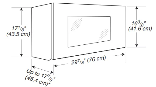
*Overall depth of product will vary slightly depending on door design.
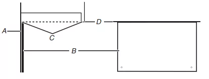
Installation Dimensions
NOTE: The grounded 3 prong outlet must be inside the upper cabinet. See the "Electrical Requirements" section.
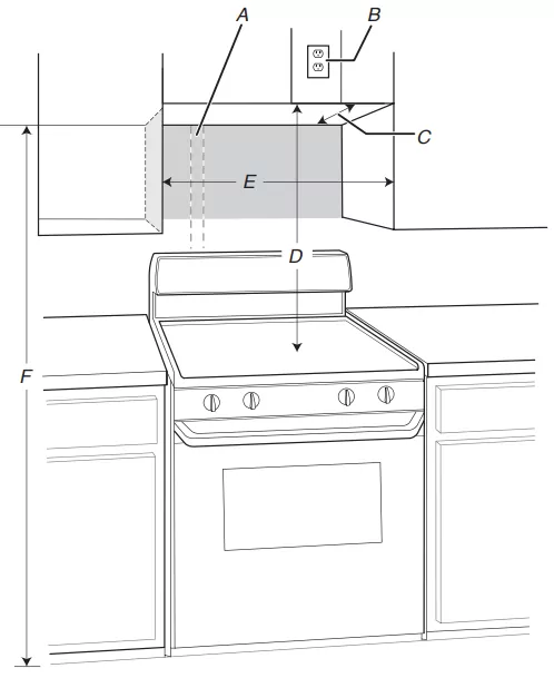
A. 2" x 4" (5.1 cm x 10.2 cm) wall stud
B. Grounded 3 prong outlet
C. 12" (30.5 cm) minimum, 14" (35.6 cm) maximum*
Exact dimensions may vary depending on type of range/cooktop below.
*Upper cabinet and side cabinet depth: 12" (30.5 cm) minimum, 14" (35.6 cm) maximum.
**30" (76.2 cm) is typical for 66" (167.6 cm) installation height.
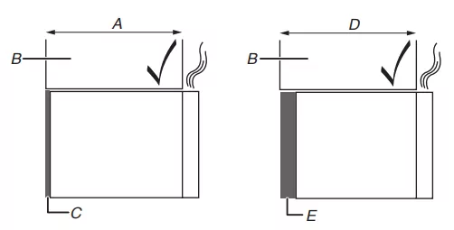
A. 12" (30.5 cm) to 14" (35.6 cm) depth of cabinet
B. Cabinet
C. Mounting plate
D. 14" (35.6 cm) to 15" (38.1 cm) depth of cabinet
E. Bump out mounting kit
NOTE: To ensure good performance, do not obstruct top vent airflow. If cabinets are larger than 14" (35.6 cm) but no more than 15" (38.1 cm) use the bump out mounting kit replacing the mounting plate from the wall. The bump out mounting kit (part # W11185746) is not provided but can be purchased from Whirlpool.
To order, see the "Online Ordering Information" section of the Quick Start Guide.
For cabinets with other dimension's, we suggest selecting other Whirlpool Products.
Electrical Requirements
Observe all governing codes and ordinances.
Required:
A 120 V, 60 Hz, AC only, 15 A or 20 A electrical supply with a fuse or circuit breaker.
Recommended:
A time- delay fuse or time- delay circuit breaker. A separate circuit serving only this microwave oven.
GROUNDING INSTRUCTIONS
For a grounded, cord-connected appliance:
This appliance must be grounded. In the event of a malfunction or breakdown, grounding will reduce the risk of electric shock by providing a path of least resistance for electric current. This appliance is equipped with a cord having an equipment- grounding conductor and a grounding plug. The plug must be plugged into an appropriate outlet that is properly installed and grounded in accordance with all local codes and ordinances.
WARNING: Improper connection of the equipment- grounding conductor can result in a risk of electric shock. Check with a qualified electrician or serviceman if you are in doubt as to whether the appliance is properly grounded. Do not modify the plug provided with the appliance: if it will not fit the outlet, have a proper outlet installed by a qualified electrician.
This device complies with Part 18 of the FCC Rules.
INSTALLATION
Prepare Microwave Oven Hood Combination
WARNING: Use two or more people to move and install or uninstall appliance. Failure to do so can result in back or other injury.
1. To avoid possible damage to the work surface, cover the work surface.
2. Separate cardboard template from the carton box, see the "Separate cardboard template" section for details.
3. Remove the screw pack from the outer foam in the carton.
4. Remove the damper from the outer foam in the carton.
5. Remove the literature pack from the outer foam in the carton.
6. Remove shipping materials, tape and film from microwave.
7. Remove the mounting plate from the outer foam in the carton.
8. Tape the microwave oven door closed so that the door does not swing open while the microwave oven is being handled.
Separate Cardboard Template
The wall template and upper cabinet template is embedded in the backside of the carton box. They are used as a rear wall template and upper cabinet template.
- Cut along the dotted line to separate the cardboard template from the backside of the carton box. Set the cardboard template to the side and refer to it during the "Mark Rear Wall" and "Prepare Upper Cabinet" parts of installation.
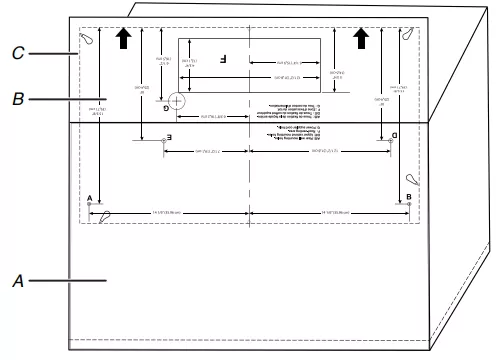
A. Backside of the carton box
B. Cardboard template (including Rear Wall template and Upper Cabinet template)
C. Dotted line
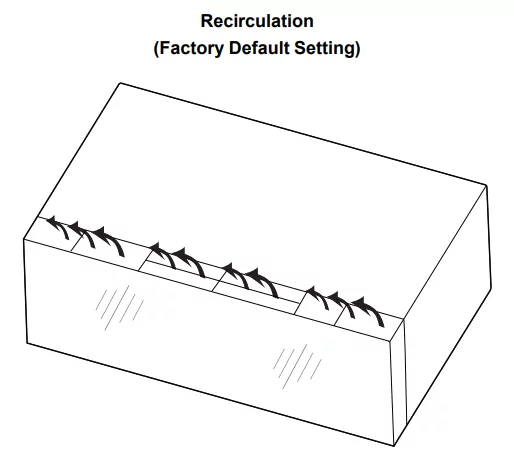
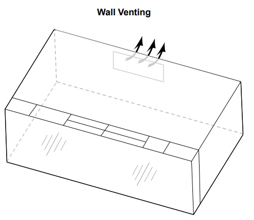
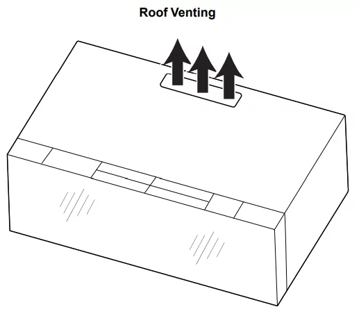
Installation Types
This microwave oven is designed for adaptation to the following three types of ventilation, choose one type before installation.
Find the Wall Stud(s)
NOTE: If no wall studs exist within the cabinet opening, do not install the microwave oven.
- Using a stud finder, locate the edges of the wall stud(s) within the opening.
- Mark the center of each stud, and draw a plumb line down each stud center. See illustrations in "Possible Wall Stud Configurations."
Possible Wall Stud Configurations
These depictions show examples of preferred installation configurations with the mounting plate.
No Wall Studs at End Holes
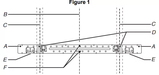
A. End holes (on mounting plate)
B. Cabinet opening vertical centerline
C. Wall stud centerlines 30" (76.2 cm) minimum
D. Holes for lag screws
E. Support tabs
F. Mounting plate center markers
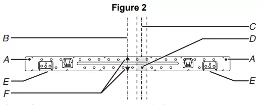
No Wall Studs at End Holes
NOTE: If wall stud is within 6" (15.2 cm) of the vertical centerline (see the "Mark Rear Wall" section), only recirculation or roof venting installation can be done.
A. End holes (on mounting plate)
B. Cabinet opening vertical centerline
C. Wall stud centerlines
D. Holes for lag screws
E. Support tabs
F. Mounting plate center markers
Wall Stud at End Holes Figure 3
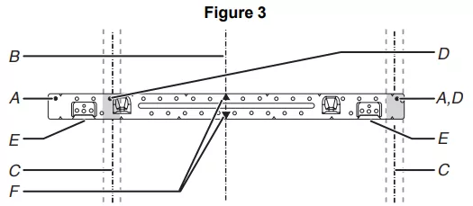
A. End holes (on mounting plate)
B. Cabinet opening vertical centerline
C. Wall stud centerlines
D. Holes for lag screws
E. Support tabs
F. Mounting plate center markers
Wall Stud at End Holes Figure 4
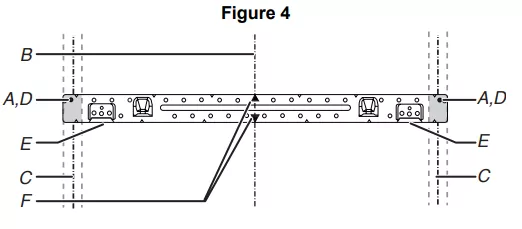
A. End holes (on mounting plate)
B. Cabinet opening vertical centerline
C. Wall stud centerlines Holes for lag screws
D. Holes for lag screws
E. Support tabs
F. Mounting plate center markers
Mark and Drill Upper Cabinet
1. Disconnect power to outlet.
2. Remove all contents from upper cabinet.
3. Using a tape, measure clearly and mark the vertical centerline of the opening. Make sure it aligns with the vertical wall centerline. Use a pencil to draw the centerlines on the upper cabinet and wall.
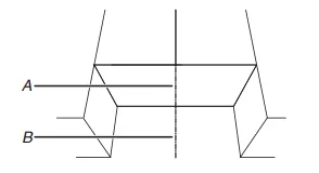
A. Upper Cabinet Centerline
B. Wall Centerline
NOTE: The cardboard plate is fit for depth of 12" to 14" (30.5 cm to 35.6 cm) cabinet installation, if cabinets are larger than 14" (35.6 cm), and up to 15" (38.1 cm), using the bump out mounting kit, replacing the mounting plate supplied with the product. The bump out mounting kit (part#- W11185746) is not provided. To order, see the "Online Ordering Information" section of the Quick Start Guide.
A. Arrows to wall
B. Upper cabinet centerline
C. Center marks on cardboard plate
4. Placing the cardboard plate against the bottom of the upper cabinet. Make sure the cardboard plate centerline aligns with the centerline on the upper cabinet which drew in step 3. And the Arrows to wall (A) must be against the rear wall so that the holes cut into the upper cabinet align with the holes in the top of the microwave oven.
NOTE: If the wall behind the microwave oven (as installed) has a partial wall covering (for example, tile back splash), be sure the "Rear Wall" arrows align to the thickest part of the rear wall (for example, the thickness of the tiles rather than the drywall).
5. Using a drill and the 3/4" (1.9 cm) hole saw cut out the power cord hole power supply hole (G on cardboard plate).
6. Drill two mounting nut holes (B), which are 3/8" (10 mm) holes at points "D" and "E" on the cardboard plate. These are for two 1/4 - 20 x 3" bolts and washers used to secure the microwave oven to the upper cabinet.
A. Power cord hole (G)
B. Mounting nut holes (D and E)
NOTE: If upper cabinet is metal, the supply cord bushing needs to be installed around the supply cord hole as shown.
A. Metal cabinet
B. Power supply cord bushing
7. Using a keyhole saw, cut out the rectangular roof venting cutout area. Skip this step if for recirculation venting or wall venting installation.
A. Roof Venting Cutout Area
Mark and Drill Rear Wall
The microwave oven must be installed on a minimum of 1 wall stud, preferably 2, using a minimum of 1 lag screw, preferably 2. See "Find the Wall Stud(s)" section for find the wall studs.
Align the center markers on the cardboard plate, to the centerline on the wall, making sure it is level, and that the top of the cardboard template is butted up against the back edge of the upper cabinet. (See following NOTE before making marks).
1. Attach the cardboard plate to wall, Align the center markers on the cardboard plate, to the centerline on the wall, making sure it is level, and that the top of the cardboard plate is butted up against the back edge of the upper cabinet. (See following NOTE before making marks).
NOTE: If the front edge of the upper cabinet is lower than the back edge, lower the cardboard template so that its top is level with the front edge of the cabinet.
A. Rear wall
B. Cardboard plate
C. Top of cardboard plate must align with front edge of cabinet.
D. Front edge of the upper cabinet
2. Drill holes at A (A and B marks on the cardboard plate), if the Wall studs are not located A and B hole, do not drill A and B hole, and follow the below instruction
A. A and B holes
B. Arrows to upper cabinet
C. Center marks on cardboard plate
D. Back edge of upper cabinet
3. In addition to being installed on at least 1 wall stud, the mounting plate must attach to the wall at both end holes. If the end holes are not over wall studs, use two 3/16-24 x 3" round head bolts with toggle nuts; if 1 end hole is over a wall stud, use 1 lag screw and one 3/16-24 x 3" round-head bolt with toggle nut; or if both end holes are over wall studs, use 2 lag screws. Following are 3 installation configurations.
Installation for No Wall Studs at End Holes (Figures 1 and 2 in Find the Wall Stud(s) section)
1. Drill 5/8" (1.6 cm) holes through the wall at both end holes marked in Step 3 of the "Mark Rear Wall."
2. Drill 3/16" (5 mm) hole(s) into the wall stud(s) at the hole(s) marked in step 6 of the "Mark Rear Wall." Refer to figures 1 and 2 in "Possible Wall Stud Configurations" in the "Locate Wall Stud(s)" section.
Installation for Wall Stud at One End Hole (Figure 3 in Find the Wall Stud(s) section)
1. Drill a 3/16" (5 mm) hole into the wall stud at the end hole marked in Step 3 of the "Mark Rear Wall."
2. If installing on a second wall stud, drill a 3/16" (5 mm) hole into the wall stud at the other hole marked in Step 6 of the "Mark Rear Wall." Refer to Figure 3 in "Possible Wall Stud Configurations" in the "Locate all Stud(s)" section.
3. Drill a 5/8" (1.6 cm) hole through the wall at the other end.
Installation for Wall Studs at Both End Holes (Figure 4 in Find the Wall Stud(s) section)
1. Drill 3/16" (5 mm) holes into the studs at the end holes marked in Step 3 of the “Mark Rear Wall.”
4. Using a keyhole saw, cut out the rectangular wall venting cutout area. Skip this step if for recirculation venting or roof venting installation.
A. Wall Venting Cutout Area
Attach Mounting Plate to Wall
1. Position mounting plate on the wall.
2. Secure the mounting plate to the wall at both end holes drilled into the wall studs and/or drywall using either 3/16-24 x 3" round-head bolts and toggle nuts or 1/4 x 2" lag screws. Refer to illustrations in "Possible Wall Stud Configurations" in the "Locate Wall Stud(s)" section, and the following sections "No Wall Studs at End Holes (Figures 1 and 2 in Find the Wall Stud(s) section)" or "Wall Stud at One End Hole (Figure 3 in Find the wall Stud(s) section)".
3. Insert lag screws into both end holes.
4. Check alignment of mounting plate, making sure it is level.
5. Secure the two end hole screws.
Instruction for No Wall Studs at End Holes (Figures 1 and 2 in Find the Wall Stud(s) section)
NOTE: The mounting plate must be secured to the wall on at least 1 wall stud as well as at both ends.
1. With the support tabs of the mounting plate facing forward, insert 3/16-24 x 3" round-head bolts through both ends of mounting plate.
2. Start toggle nuts on bolts from the back of the mounting plate. Leave enough space for the toggle nuts to go through the wall and to open.
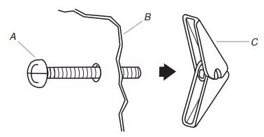
A. 3/16-24 x 3" round-head bolt
B. Mounting plate
C. Spring toggle nut
3. Position mounting plate on the wall.
4. Push the 2 bolts with toggle nuts through the drywall, and finger tighten the bolts to make sure toggle nuts have opened against drywall.
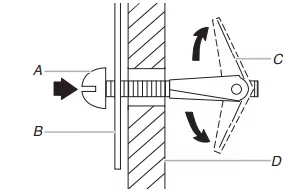
A. 3/16-24 x 3" round-head bolt
B. Mounting plate
C. Spring toggle nut
D. Drywall
5. Insert lag screw(s) into the hole(s) drilled into wall stud(s) in Step 2 of "Installation for No Wall Studs at End Holes" in the "Drill Holes in Rear Wall" section.
6. Check alignment of mounting plate, making sure it is level.
7. Securely tighten all lag screws and bolts.
Wall Stud at One End Hole (Figure 3 in Find the Wall Stud(s) section)
1. With the support tabs of the mounting plate facing forward, insert a 3/16-24 x 3" round-head bolt through the end hole that fits over the 5/8" (16 mm) hole drilled in step 3 of "Installation for Wall Stud at One End Hole" in the "Drill Holes in Rear Wall" section.
2. Start a toggle nut on the bolt from the back of the mounting plate. Leave enough space for the toggle nut to go through the wall and to open.
3. Position mounting plate on the wall.
4. Push the bolt with toggle nut through the drywall, and finger tighten the bolt to make sure toggle nut has opened against drywall.
5. Insert a lag screw into the remaining end hole.
6. If installing on a second wall stud, insert a lag screw into the other hole drilled in Step 2 of "Installation for Wall Stud at One End Hole" in the "Drill Holes in Rear Wall" section. Check alignment of mounting plate, making sure it is level.
7. Securely tighten the lag screw(s) and bolt.
Wall Studs at Both End Holes (Figure 4)
1. Position mounting plate on the wall.
2. Insert lag screws into both end holes.
3. Check alignment of mounting plate, making sure it is level.
4. Securely tighten the lag screws.
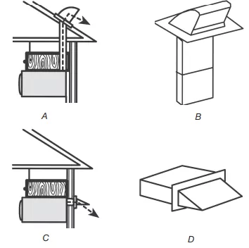
Rotate Blower Motor
This section include wall and roof venting installation, both venting installation need rotate blower motor, select one ventilation type before install the microwave oven. And follow the propritated instruction to rotate the blower motor. If for recirculation installation, no need to rotate the blower motor, this section can be skip.
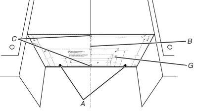
Rotate Blower Motor for Wall Venting Installation
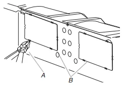
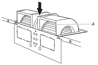
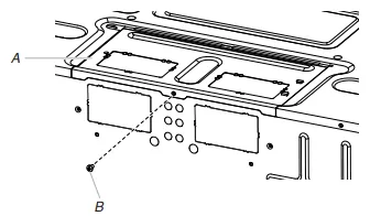
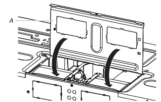
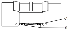
1. Remove screws attaching damper plate to back of microwave oven, set the screws aside.
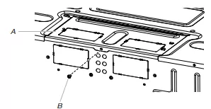
A. Damper plate
B. Screw
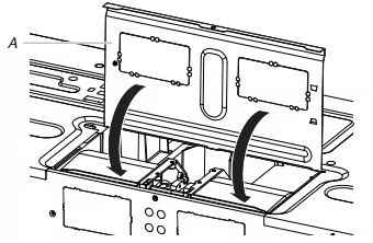
2. Turn and hold the damper plate vertically as shown.
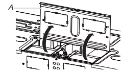
A. Damper plate
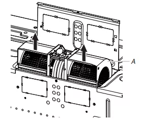
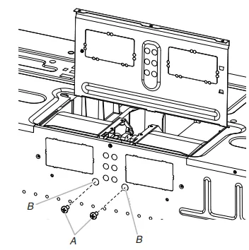
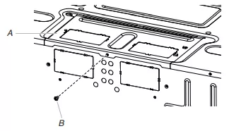
3. Remove 2 blower screws attaching blower motor to the microwave oven, and set aside.
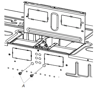
A. Blower screws
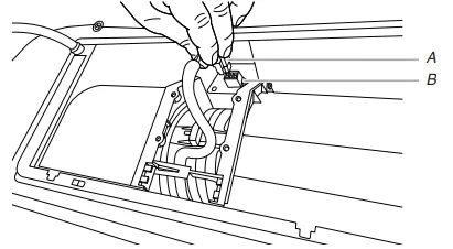
4. Disconnect the blower motor wire from the connector.
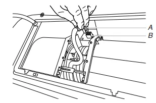
A. Blower motor wire
B. Connector
5. Lift blower motor out of microwave oven, and set aside.
A. Blower motor
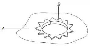
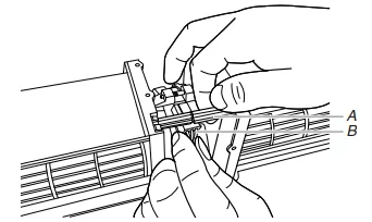
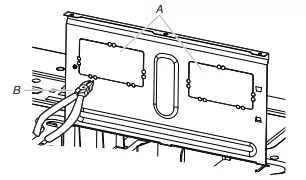
6. Using diagonal wire cutting pliers, gently snip out the rectangular damper vent covers at the perforations.
A. Diagonal wire cutting pliers
B. Rectangular damper vent cover
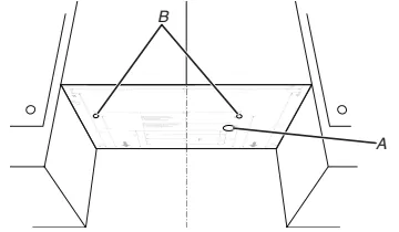
7. Hold the blower motor wire, put the wire through the blower motor bridge.
A. Blower motor bridge
B. Blower motor wire
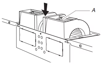
8. Lower blower motor back into the microwave oven. Exhaust ports face the back of the microwave oven.
A. Exhaust Port
9. Reconnect the blower motor wire into the connector.
A. Blower motor wire
B. Connector
10. Reattach the 2 blower screws into the recessed holes in the back of the microwave.
A. Screws
B. Holes
11. Check to make sure the 2 screws are secured properly in the blower motor screw holes, so that the motor cannot move.
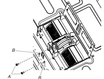
A. Screws
B. Blower motor screw holes
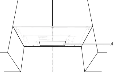
12. Return the damper plate to its original horizontal position.
A. Damper plate
13. Secure damper plate with 2 screws removed in Step 1.
A. Damper plate
B. Screw
14. Plug in the microwave oven. Check if the vent fan runs with abnormal sounds, go back through the steps to see which step was skipped.
Rotate Blower Motor for Roof Venting Installation
1. Repeat Steps 1 to 5 from "Wall Venting Installation Only."
2. Using diagonal wire cutting pliers, gently snip out the rectangular vent covers on the damper plate at the perforations.
A. Rectangular vent covers
B. Diagonal wire cutting pliers
3. Lower blower motor back into microwave oven. Exhaust ports face the top of microwave oven.
A. Exhaust port
IMPORTANT: If blower motor is not positioned with flat side facing the back of the microwave oven (as shown), performance will be poor.
4. Reconnect the blower motor wire into the connector.
5. Reattach the 2 blower screws into the recessed holes in the back of the microwave.
6. Check to make sure the 2 screws are secured properly in the blower motor screw holes, so that the motor cannot move.
7. Return the damper plate to its original horizontal position.
A. Damper plate
8. Secure damper plate with screw removed in Step 1.
A. Damper plate
B. Screw
9. Repeat Step 14 from "Wall Venting Installation Only."
Install Damper Assembly
If for recirculation installation, no need to install the damper assembly, this section can be skip. And save it for future use.
Install Damper (For Wall Venting)
1. Find the damper in outer foam in the carton.
2. Check that damper blade moves freely, and opens fully.
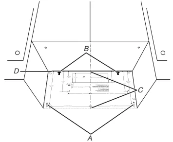
3. Position the damper assembly on the back of the microwave oven so that the damper blade hinge is at the top, and the damper blade opens away from the microwave oven.
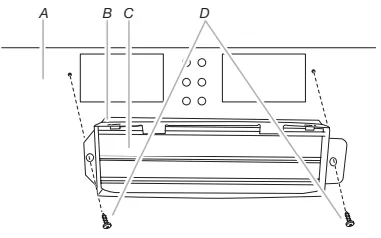
A. Back of microwave oven
C. Damper blade
B. Damper assembly
D. #6 x 3/8" Sheet metal screws (in the screw pack)
4. Secure damper assembly with two #6 x 3/8" sheet metal screws, see above illustration.
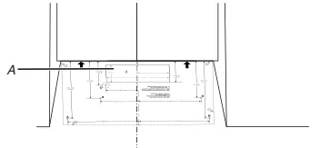
Install Damper (For Roof Venting)
1. Find the damper in outer foam in the carton.
2. Check that damper blade moves freely and opens fully.
3. Insert damper assembly through the cabinet cutout so that the long tab of the damper assembly slides under the raised tabs of the damper plate. Then secure with #6 x 3/8" sheet metal screw.
NOTE: The screw cannot be installed if the damper assembly is not positioned as shown.
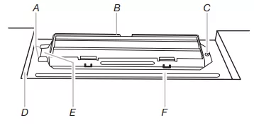
A. Raised tabs
D. Upper cabinet cutout
B. Damper assembly
E. Long tab
C. #6 x 3/8" Sheet metal screws
F. Damper plate
Install the Microwave Oven
WARNING: Use two or more people to move and install or uninstall appliance. Failure to do so can result in back or other injury.
IMPORTANT: The control side of the microwave oven is the heavy side. Handle the microwave oven gently.
1. Place a washer on each 1/4 - 20 x 3" (7.6 cm) flat-head bolt and place inside upper cabinet near the 3/8" (9.5 mm) holes.
2. Make sure the microwave oven door is closed and taped shut.
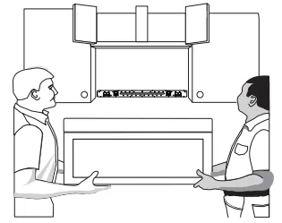
3. Using 2 or more people, lift microwave oven and hang it on support tabs at the bottom of mounting plate.
NOTE: To avoid damage to the microwave oven, do not grip or use the door or while the microwave oven is being handled.
A. Mounting plate
B. Support tabs
4. With front of microwave oven still tilted, thread power supply cord through the power supply cord hole in the bottom of the upper cabinet.
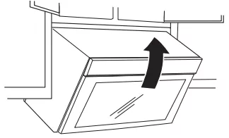
5. Rotate microwave oven up toward upper cabinet.
NOTE: If venting through the wall, make sure the damper assembly fits easily into the vent in the wall cutout.
6. Push microwave oven against mounting plate and hold in.
NOTE: If microwave oven does not need to be adjusted, skip steps 7 through 9.
7. If adjustment is required, rotate microwave oven downward. Using 2 or more people, lift microwave oven off of mounting plate and set aside on a covered surface.
8. Loosen mounting plate screws. Adjust mounting plate and re-tighten screws.
9. Repeat steps 3 through 6.
10. With the microwave oven centered, and with at least one person holding it in place, insert bolts through upper cabinet into microwave oven. Tighten bolts until there is no gap between upper cabinet and microwave oven.
NOTE: Some upper cabinets may require bolts longer or shorter than 3" (7.6 cm). Longer or shorter bolts are available at most hardware stores. Overtightening bolts may warp the top of the microwave oven. To avoid warping, wood filter blocks (installer to provide) may be added. The blocks must be the same thickness as the space between the upper cabinet bottom and the microwave oven.
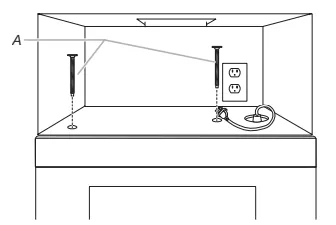
A. Bolts
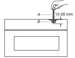
Avoid damage to the mounting nut, screw the bolts into the mounting nut holes around 15 - 20 mm by hand first, make sure the bolts thread in properly. Then tighten with tools.
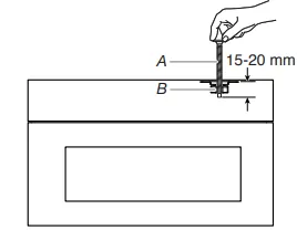
A. Bolt
B. Mounting Nut
11. Connect vent to damper assembly.
A. Vent
B. Damper assembly (under vent) Compact
Complete Installation
1. Plug microwave oven into grounded 3 prong outlet.
2. Reconnect power.
3. Check the operation of microwave oven by placing 1 cup (250 mL) of water on the turntable and programming a cook time of 1 minute at 100% power. Test vent fan and exhaust by operating the vent fan.
4. If the microwave oven does not operate: Check that a household fuse has not blown, or that a circuit breaker has not tripped. Replace the fuse or reset the circuit breaker. If the problem continues, call an electrician. Check that the power supply cord is plugged into a grounded 3 prong outlet.
5. See the Quick Start Guide for more informations.
The installation is now complete.
Save this owner manual for future use.
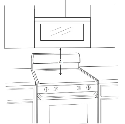
A. 12 1/8" (33 cm) is the height from the highest point of the stove to the bottom of the microwave oven.
VENTING DESIGN SPECIFICATIONS
This section is intended for architectural designer and builder/contractor reference only.
NOTES:
- Vent materials needed for installation are not provided with microwave hood combination.
- We do not recommend using a flexible metal vent.
- To avoid possible product damage, be sure to vent air outside, unless using recirculation installation. Do not vent exhaust air into concealed spaces, such as spaces within walls or ceilings, attics, crawl spaces or garages.
For optimal venting installation, we recommend:
- Using roof or wall caps that have backdraft dampers.
- Using a rigid metal vent.
- Using the most direct route by minimizing the length of the vent and number of elbows to provide efficient performance.
- Using uniformly sized vents.
- Using duct tape to seal all joints in the vent system.
- Using caulking compound to seal exterior wall or roof opening around cap.
- Not installing 2 elbows together, for optimal hood performance.
If venting through the wall, be sure that there is proper clearance within the wall for the damper to open fully.
If venting through the roof, and rectangular- to- round transition is used, be sure there are at least 3" (7.6 cm) of clearance between the top of the microwave oven and the transition piece. See "Rectangular- to- Round Transition" illustration.
A. Roof venting
B. Roof cap
C. Wall venting
D. Wall cap
Rectangular-to-Round Transition
NOTE: The minimum 3" (7.6 cm) clearance must exist between the top of the microwave oven and the rectangular- to- round transition piece so that the damper can open freely and fully.
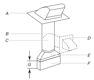
A. Roof cap
B. 6" (152 mm) minimum diameter round vent
C. Elbow (for wall venting only)
D. Wall cap
E. 3 1/4 x 10" to 6" (8.3 x 25.4 cm to 15.2 cm) a rectangular-to-round transition piece
F. Vent extension piece, at least 3" (7.6 cm) high
G. 3" (7.6 cm)
Recommended Standard Fittings
NOTE: The minimum 3" (7.6 cm) clearance must exist between the top of the microwave oven and the rectangular- to- round transition piece so that the damper can open freely and fully.
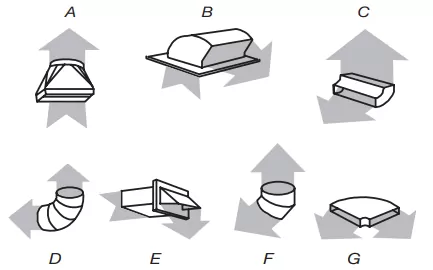
A. Rectangular-to-round transition piece: 3 1/4" x 10" to 6" = 5 ft (8.3 x 25.4 cm to 15.2 cm = 1.5 m)
B. Roof cap: 3 1/4" x 10" = 24 ft (8.3 x 25.4 cm = 7.3 m)
C. 90° elbow: 3 1/4" x 10" = 25 ft (8.3 x 25.4 cm = 7.6 m)
D. 90° elbow: 6" = 10 ft (15.2 cm = 3 m)
E. Wall cap: 3 1/4" x 10" = 40 ft (8.3 x 25.4 cm = 12.2 m)
F. 45° elbow: 6" = 5 ft (15.2 cm = 1.5 m)
G. 90° flat elbow: 3 1/4" x 10" = 10 ft (8.3 x 25.4 cm = 3 m)
Recommended Vent Length
A 3 1/4" x 10" (8.3 x 25.4 cm) rectangular or 6" (15.2 cm) round vent should be used.
The total length of the vent system including straight vent, elbow(s), transitions and wall or roof caps must not exceed the equivalent of 140 ft (42.7 m) for either type of vent. See the "Recommended Standard Fittings" section for equivalent lengths. For best performance, use no more than three 90° elbows.
3 1/4" x 10" (8.3 x 25.4 cm) vent system = 73 ft (22.2 m) total
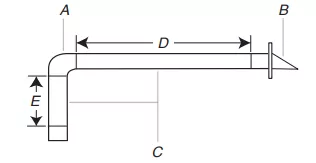
A. One 3 1/4" x 10" (8.3 x 25.4 cm) 90° elbow = 25 ft (7.6 m)
B. 1 wall cap = 40 ft (12.2 m)
C. 2 ft (0.6 m) + 6 ft (1.8 m) straight = 8 ft (2.4 m)
D. 6 ft (1.8 m)
E. 2 ft (0.6 m)
6" (152 mm) vent system = 73 ft (22.2 m) total
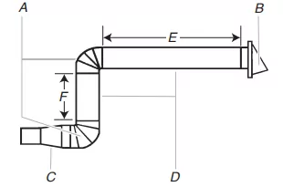
A. Two 90° elbows = 20 ft (6.1 m)
B. 1 wall cap = 40 ft (12.2 m)
C. 1 rectangular-to-round transition piece = 5 ft (1.5 m)
D. 2 ft (0.6 m) + 6 ft (1.8 m) straight = 8 ft (2.4 m)
E. 6 ft (1.8 m)
F. 2 ft (0.6 m)
If the existing vent is round, a rectangular to round transition piece must be used. In addition, a rectangular 3" (7.6 cm) extension vent between the damper assembly and rectangular to round transition piece must be installed to keep the damper from sticking.