
0
DS-6900UDI(C) Series
Ultra HD Video and Audio Decoder
User Manual
DS-6900UDI(C) Series Ultra HD Video and Audio Decoder • User Manual
I
Legal Information
About this Document
●
This Document includes instructions for using and managing the Product. Pictures, charts, images and all other
information hereinafter are for description and explanation only.
●
The information contained in the Document is subject to change, without notice, due to firmware updates or other
reasons. Please find the latest version of the Document at the Hikvision website (https://www.hikvision.com).
Unless otherwise agreed, Hangzhou Hikvision Digital Technology Co., Ltd. or its affiliates (hereinafter referred to as
"Hikvision") makes no warranties, express or implied.
●
Please use the Document with the guidance and assistance of professionals trained in supporting the Product.
About this Product
●
This product can only enjoy the after-sales service support in the country or region where the purchase is made.
●
If the product you choose is a video product, please scan the following QR code to obtain the "Initiatives on the Use
of Video Products", and read it carefully.
Acknowledgment of Intellectual Property Rights
●
Hikvision owns the copyrights and/or patents related to the technology embodied in the Products described in this
Document, which may include licenses obtained from third parties.
●
Any part of the Document, including text, pictures, graphics, etc., belongs to Hikvision. No part of this Document
may be excerpted, copied, translated, or modified in whole or in part by any means without written permission.
●
and other Hikvision’s trademarks and logos are the properties of Hikvision in various
jurisdictions.
●
Other trademarks and logos mentioned are the properties of their respective owners.
●
The terms HDMI and HDMI High-Definition Multimedia Interface, and the HDMI Logo are trademarks or
registered trademarks of HDMI Licensing Administrator, Inc. in the United States and other countries.
LEGAL DISCLAIMER
●
TO THE MAXIMUM EXTENT PERMITTED BY APPLICABLE LAW, THIS DOCUMENT AND THE PRODUCT DESCRIBED,
WITH ITS HARDWARE, SOFTWARE AND FIRMWARE, ARE PROVIDED "AS IS" AND "WITH ALL FAULTS AND ERRORS".
HIKVISION MAKES NO WARRANTIES, EXPRESS OR IMPLIED, INCLUDING WITHOUT LIMITATION, MERCHANTABILITY,

DS-6900UDI(C) Series Ultra HD Video and Audio Decoder • User Manual
II
SATISFACTORY QUALITY, OR FITNESS FOR A PARTICULAR PURPOSE. THE USE OF THE PRODUCT BY YOU IS AT YOUR
OWN RISK. IN NO EVENT WILL HIKVISION BE LIABLE TO YOU FOR ANY SPECIAL, CONSEQUENTIAL, INCIDENTAL, OR
INDIRECT DAMAGES, INCLUDING, AMONG OTHERS, DAMAGES FOR LOSS OF BUSINESS PROFITS, BUSINESS
INTERRUPTION, OR LOSS OF DATA, CORRUPTION OF SYSTEMS, OR LOSS OF DOCUMENTATION, WHETHER BASED
ON BREACH OF CONTRACT, TORT (INCLUDING NEGLIGENCE), PRODUCT LIABILITY, OR OTHERWISE, IN CONNECTION
WITH THE USE OF THE PRODUCT, EVEN IF HIKVISION HAS BEEN ADVISED OF THE POSSIBILITY OF SUCH DAMAGES
OR LOSS.
●
YOU ACKNOWLEDGE THAT THE NATURE OF THE INTERNET PROVIDES FOR INHERENT SECURITY RISKS, AND
HIKVISION SHALL NOT TAKE ANY RESPONSIBILITIES FOR ABNORMAL OPERATION, PRIVACY LEAKAGE OR OTHER
DAMAGES RESULTING FROM CYBER-ATTACK, HACKER ATTACK, VIRUS INFECTION, OR OTHER INTERNET SECURITY
RISKS; HOWEVER, HIKVISION WILL PROVIDE TIMELY TECHNICAL SUPPORT IF REQUIRED.
●
YOU AGREE TO USE THIS PRODUCT IN COMPLIANCE WITH ALL APPLICABLE LAWS, AND YOU ARE SOLELY
RESPONSIBLE FOR ENSURING THAT YOUR USE CONFORMS TO THE APPLICABLE LAW. ESPECIALLY, YOU ARE
RESPONSIBLE, FOR USING THIS PRODUCT IN A MANNER THAT DOES NOT INFRINGE ON THE RIGHTS OF THIRD
PARTIES, INCLUDING WITHOUT LIMITATION, RIGHTS OF PUBLICITY, INTELLECTUAL PROPERTY RIGHTS, OR DATA
PROTECTION AND OTHER PRIVACY RIGHTS. YOU SHALL NOT USE THIS PRODUCT FOR ANY PROHIBITED END-USES,
INCLUDING THE DEVELOPMENT OR PRODUCTION OF WEAPONS OF MASS DESTRUCTION, THE DEVELOPMENT OR
PRODUCTION OF CHEMICAL OR BIOLOGICAL WEAPONS, ANY ACTIVITIES IN THE CONTEXT RELATED TO ANY
NUCLEAR EXPLOSIVE OR UNSAFE NUCLEAR FUEL-CYCLE, OR IN SUPPORT OF HUMAN RIGHTS ABUSES.
●
IN THE EVENT OF ANY CONFLICTS BETWEEN THIS DOCUMENT AND THE APPLICABLE LAW, THE LATTER PREVAILS.
© Hangzhou Hikvision Digital Technology Co., Ltd. All rights reserved.
DS-6900UDI(C) Series Ultra HD Video and Audio Decoder • User Manual
III
Regulatory Information
FCC Information
Please take attention that changes or modification not expressly approved by the party responsible
for compliance could void the user’s authority to operate the equipment.
FCC Compliance
This equipment has been tested and found to comply with the limits for a Class A digital device,
pursuant to part 15 of the FCC Rules. These limits are designed to provide reasonable protection
against harmful interference when the equipment is operated in a commercial environment. This
equipment generates, uses, and can radiate radio frequency energy and, if not installed and used in
accordance with the instruction manual, may cause harmful interference to radio communications.
Operation of this equipment in a residential area is likely to cause harmful interference in which
case the user will be required to correct the interference at his own expense.
FCC Conditions
This device complies with part 15 of the FCC Rules. Operation is subject to the following two
conditions:
1. This device may not cause harmful interference.
2. This device must accept any interference received, including interference that may cause
undesired operation.
EU Conformity Statement
This product and - if applicable - the supplied accessories too are marked with "CE" and
comply therefore with the applicable harmonized European standards listed under the
EMC Directive 2014/30/EU, the LVD Directive 2014/35/EU, the RoHS Directive 2011/65/EU.
2012/19/EU (WEEE directive): Products marked with this symbol cannot be disposed of as
unsorted municipal waste in the European Union. For proper recycling, return this product
to your local supplier upon the purchase of equivalent new equipment, or dispose of it at
designated collection points. For more information see: www.recyclethis.info
2006/66/EC (battery directive): This product contains a battery that cannot be disposed
of as unsorted municipal waste in the European Union. See the product documentation
for specific battery information. The battery is marked with this symbol, which may include
lettering to indicate cadmium (Cd), lead (Pb), or mercury (Hg). For proper recycling, return the
battery to your supplier or to a designated collection point. For more information see:
www.recyclethis.info
Industry Canada ICES-003 Compliance
This device meets the CAN ICES-3 (A)/NMB-3(A) standards requirements.
DS-6900UDI(C) Series Ultra HD Video and Audio Decoder • User Manual
IV
Applicable Models
This manual is applicable to the models listed in the following table.
Series
Model
DS-6900UDI Decoder
DS-6901UDI(C)
DS-6904UDI(C)
DS-6908UDI(C)
DS-6910UDI(C)
DS-6912UDI(C)
DS-6916UDI(C)
About the Default
Item
Default Value
User name
admin
Device IP address
192.0.0.64
SSH login
User name: admin
Password: same as the device
Symbol Conventions
The symbols that may be found in this document are defined as follows.
Safety Instructions
Symbol
Description
Provides additional information to emphasize or supplement
important points of the main text.
Indicates a potentially hazardous situation, which if not avoided,
could result in equipment damage, data loss, performance
degradation, or unexpected results.
Indicates a hazard with a high level of risk, which if not avoided, will
result in death or serious injury.

DS-6900UDI(C) Series Ultra HD Video and Audio Decoder • User Manual
V
Proper configuration of all passwords and other security settings is the responsibility of the
installer and/or end-user.
In the use of the product, you must be in strict compliance with the electrical safety
regulations of the nation and region. Please refer to technical specifications for detailed
information.
Use the power adapter delivered with the device only.
If the product does not work properly, please contact your dealer or the nearest service
center. Never attempt to disassemble the product yourself. (We shall not assume any responsibility
for problems caused by unauthorized repair or maintenance.)
If smoke, odor or noise rise from the device, turn off the power at once and unplug the power
cable, and then please contact the service center.
Please enhance the protection for personal information and data security as the device may
be confronted with the network security problems when it is connected to the Internet. Please
contact your dealer or the nearest service center once you find that there may be the network
security problems.
Proper configuration of all passwords and other security settings is the responsibility of the
installer and/or end-user.
Do not drop the device or subject it to physical shock, and do not expose it to high
electromagnetism radiation. Avoid the equipment installation on vibrations surface or places
subject to shock (ignorance can cause equipment damage).
Do not expose the device to the explosive situation.
Keep clean and dry on the surface of the device.
Do not touch the exposed connection points or components when the device is powered on.
The equipment is a system level monitoring device, usually placed in the central computer
room of each level of monitoring system for use. The selection of its installation site should comply
with the relevant standards for the construction of computer rooms in the country and region
where it is used.
The equipment is a standard rack, mounted device fixed in the cabinet for use. Please pay
attention to the following during installation and use:
Ensure that the temperature inside the cabinet is within the range of 0 °C~45 °C.
Ensure that the humidity in the computer room is between 10%~90% RH.
Ensure that the cabinet is sturdy enough to support the weight of the equipment and its
accessories, and pay attention to avoiding hazards caused by uneven mechanical loads during
installation.
Ensure that there is sufficient installation space for the video and audio cables, and the
bending radius of the cables should not be less than 5 times the outer diameter of the cables.

DS-6900UDI(C) Series Ultra HD Video and Audio Decoder • User Manual
VI
Ensure a good ventilation environment, and it is recommended to install the equipment with a
ground clearance of more than 50 cm.

DS-6900UDI(C) Series Ultra HD Video and Audio Decoder • User Manual
VII
Contents
Chapter 1 Introduction ............................................................................................................... 1
1.1 Provisons ............................................................................................................................................................... 1
1.2 Product Introduction ............................................................................................................................................ 1
1.3 Manangement Software Description .................................................................................................................... 1
Chapter 2 Video Wall Configuration............................................................................................ 2
2.1.Web Login ............................................................................................................................................................. 2
2.2 Video Wall Configuration ...................................................................................................................................... 3
2.2.1 Edit Video Wall Dimensions ....................................................................................................................... 3
2.2.2 Connect with Video Wall ........................................................................................................................... 4
2.2.3 Other Configurations ................................................................................................................................. 6
2.3 Network Signal Source Management ................................................................................................................... 8
2.3.1 Add by IP Address ...................................................................................................................................... 8
2.3.2 Add by DDNS ............................................................................................................................................ 11
2.3.3 Add by URL ............................................................................................................................................... 12
2.4 Video Wall Operation ......................................................................................................................................... 13
2.4.1 Edit Decoding Window............................................................................................................................. 14
2.4.2 Signal Source Operations ......................................................................................................................... 16
2.4.3 View Decoding Status .............................................................................................................................. 16
2.4.4 Scene Management ................................................................................................................................. 17
Chapter 3 General Configuration .............................................................................................. 19
3.1 System Configuration .......................................................................................................................................... 19
3.1.1 Check Basic Information .......................................................................................................................... 19
3.1.2 Configure Time Settings ........................................................................................................................... 19
3.1.3 Configure Serial Ports .............................................................................................................................. 21
3.1.4 Manage Users .......................................................................................................................................... 24
3.2 Network Configuration ....................................................................................................................................... 27
3.2.1 Configure Network Parameters ............................................................................................................... 27
3.2.2 Configure HTTP(S) .................................................................................................................................... 27
3.3 Configure Encoding Devices ................................................................................................................................ 28
3.4 Event Configuration ............................................................................................................................................ 30
3.4.1 Configure Device Exception Alarms ......................................................................................................... 31
3.4.2 Configure Device Working Status Alarms ................................................................................................ 31
3.5 Other Settings ..................................................................................................................................................... 32
3.5.1 Split Image to Get Sub-stream ................................................................................................................. 32
3.5.2 Configure Display Settings ....................................................................................................................... 32
3.5.3 Configure Decoding Delay ........................................................................................................................ 33
Chapter 4 Maintenance and Security ........................................................................................ 34
4.1 System Maintenance .......................................................................................................................................... 34
4.1.1 Reboot...................................................................................................................................................... 34
4.1.2 Upgrade ................................................................................................................................................... 34
4.1.3 Backup and Restore ................................................................................................................................. 34

DS-6900UDI(C) Series Ultra HD Video and Audio Decoder • User Manual
VIII
4.1.4 Log ............................................................................................................................................................ 36
4.1.5 Device Debugging .................................................................................................................................... 36
4.2 Security Management ......................................................................................................................................... 37
4.2.1 IP Filtering Control ................................................................................................................................... 37
4.2.2 Certificate Management .......................................................................................................................... 38
4.2.3 SADP ......................................................................................................................................................... 39
4.2.4 Syslog ....................................................................................................................................................... 39
4.2.5 WebSocket ............................................................................................................................................... 39
Chapter 5 Device Information ................................................................................................... 40
5.1 Check Device Status ............................................................................................................................................ 40
5.2 Screen Maintenance ........................................................................................................................................... 40
Chapter 6 More Information..................................................................................................... 43

DS-6900UDI(C) Series Ultra HD Video and Audio Decoder • User Manual
1
Chapter 1 Introduction
1.1 Provisons
In order to simplify the description, the following provisions are made in this manual:
Smart Wall software are referred to as “Client Software”.
“Click” means clicking the left mouse button. “Double Click” refers to double clicking the left
mouse button. “Right Click” means clicking the right mouse button.
The figures in this manual are only examples, please refer to the actual software interface for
details.
1.2 Product Introduction
DS-6900UDI(C) series decoder is developed on the basis of embedded hardware platform, and it
supports multiple video stream formats like H.265, H.264+, H.264, with strong decoding
performance and supports 4K30 ultra high definition output. It is widely used in various video
monitoring system projects.
1.3 Manangement Software Description
The decoder can be managed and configured through the Smart Wall Client. For specific operation
methods, please refer to Chapter 5 Device Information. You can also manage and configure
through the corresponding platform software. For platform software operations, please refer to
the corresponding manual.
DS-6900UDI(C) Series Ultra HD Video and Audio Decoder • User Manual
2
Chapter 2 Video Wall Configuration
You can add signal source, decode video on the video wall, manage scenes, and so on, through the
web.
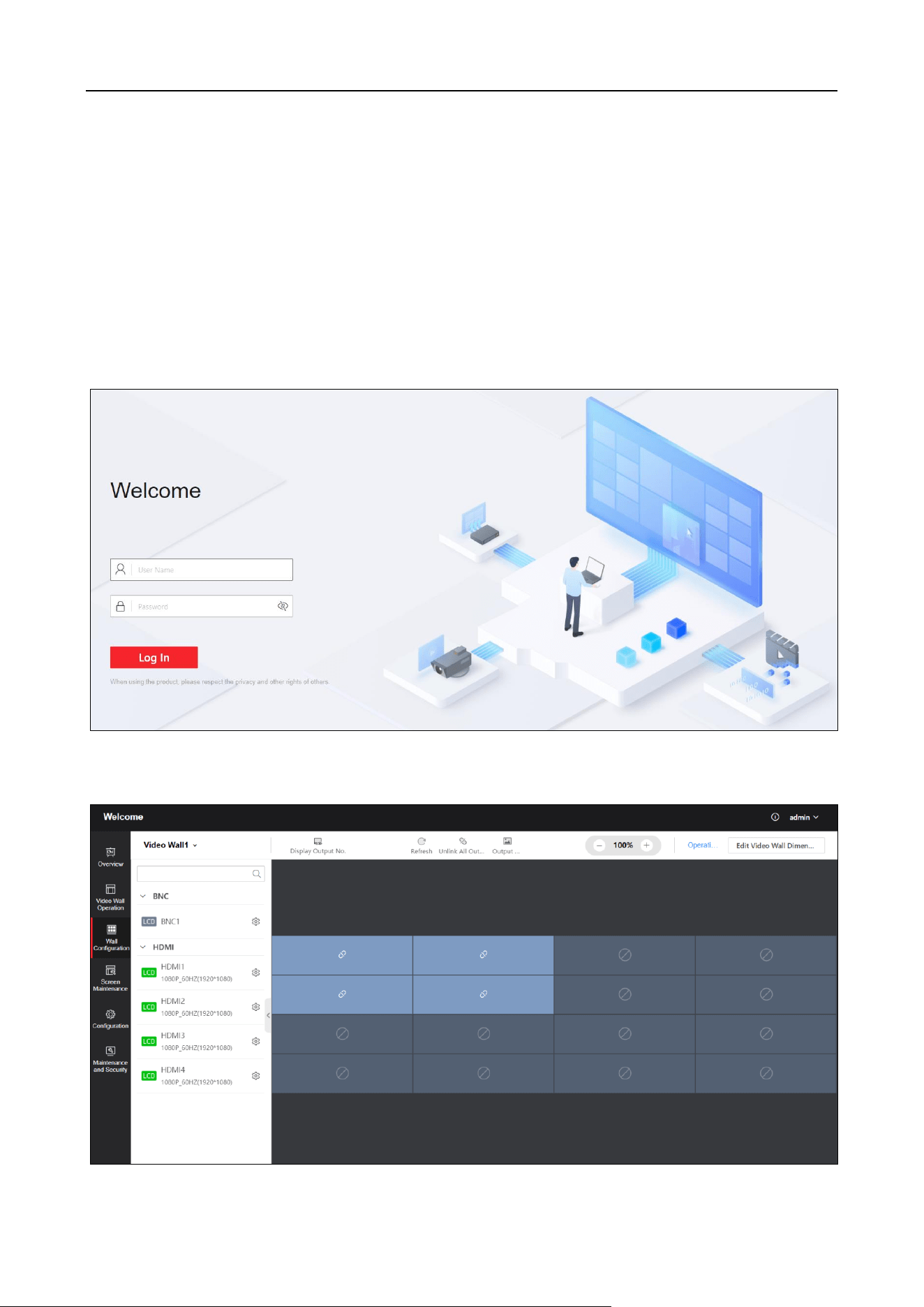
2.1.Web Login
Enter the IP address of the decoder on the address bar of web browser, and enter the user name
and password in the login page.
Figure 2-1 Login Page
Click Login to enter the Welcome page.
DS-6900UDI(C) Series Ultra HD Video and Audio Decoder • User Manual
3
Figure 2-2 Welcome Page
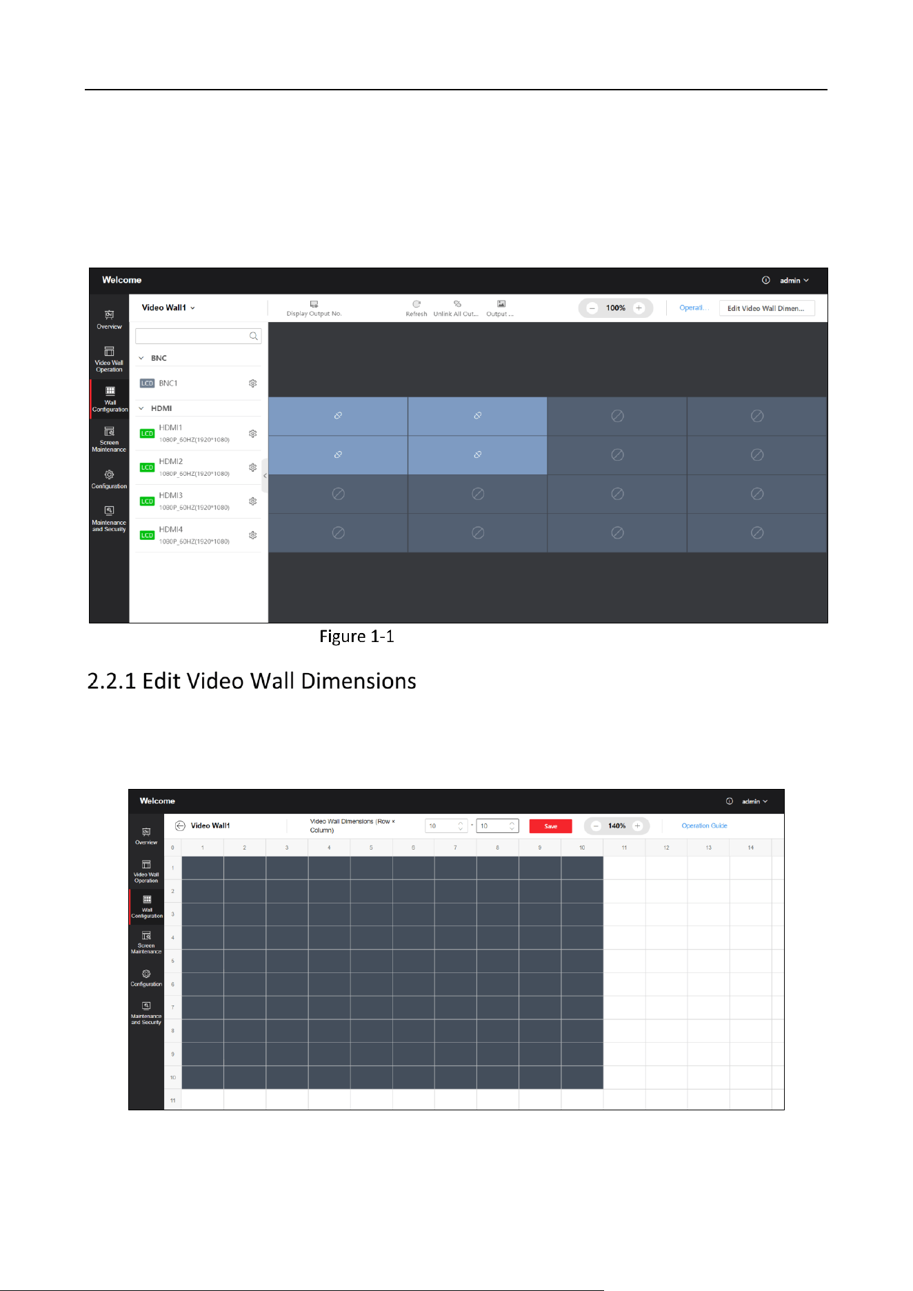
2.2 Video Wall Configuration
Click Video Wall Configuration to enter the corresponding page.
Video Wall Configuration
Click Video Wall Configuration > Edit Video Wall Dimensions in the upper-right corner of
the page to set video wall dimensions (row × column). Enter the number of screens in row
and column. Click Save.
Figure 2-4 Edit Video Wall Dimensions
DS-6900UDI(C) Series Ultra HD Video and Audio Decoder • User Manual
4
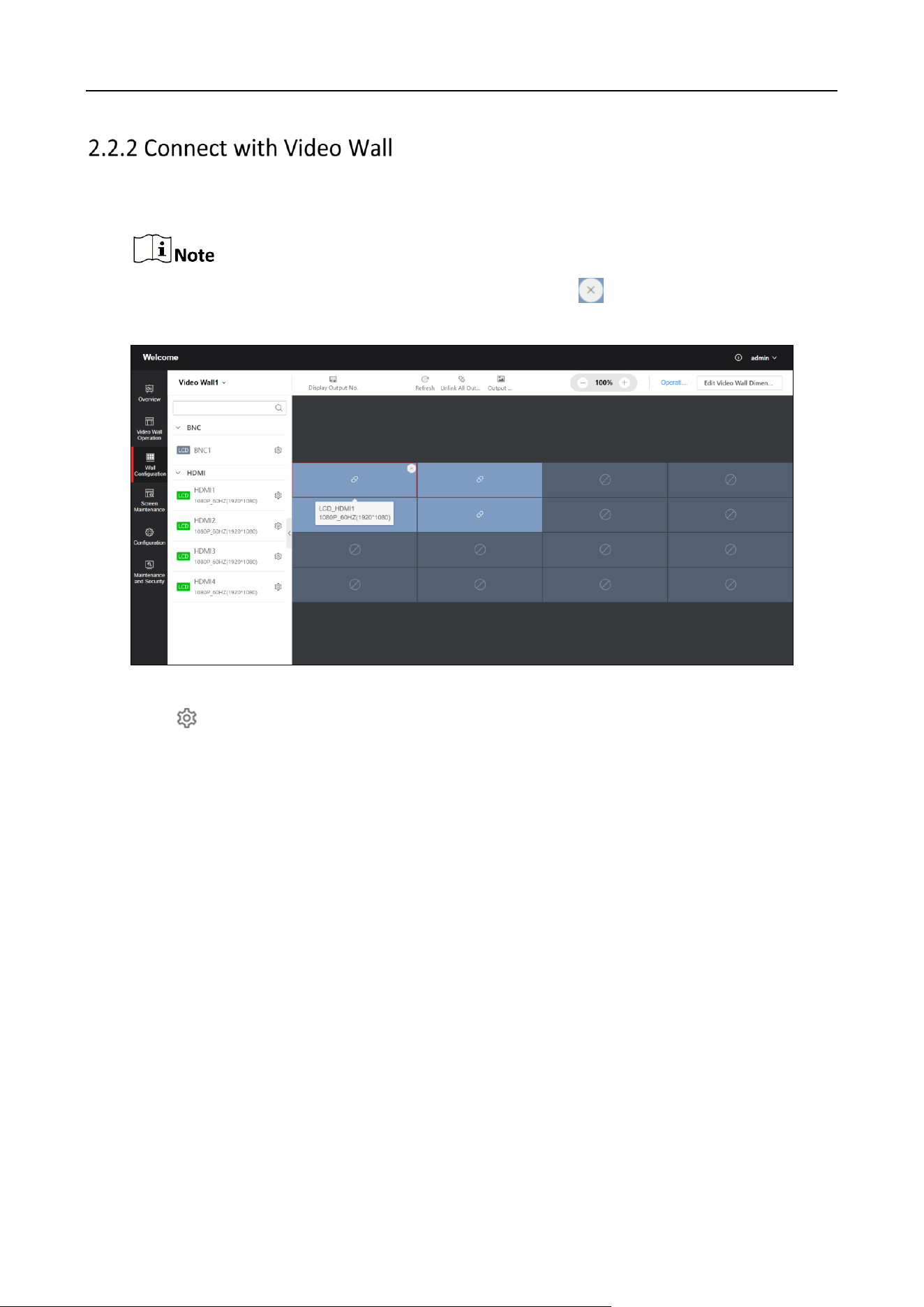
Click Video Wall Configuration to drag the output channels from the left-side list to the right
display screen to connect them with the video wall.
If all screens of the current video wall are connected, click to cancel the connection first
and then drag the output channels to connect once again.
Figure 2-5 Connect with Video Wall
Click of the output port in the left list to configure the output mode and resolution.
BNC Output Port
Output Name: Customize a name.
Video Format: Select according to actual needs.
Copy To: Copy the BNC output port configuration to other decoders.
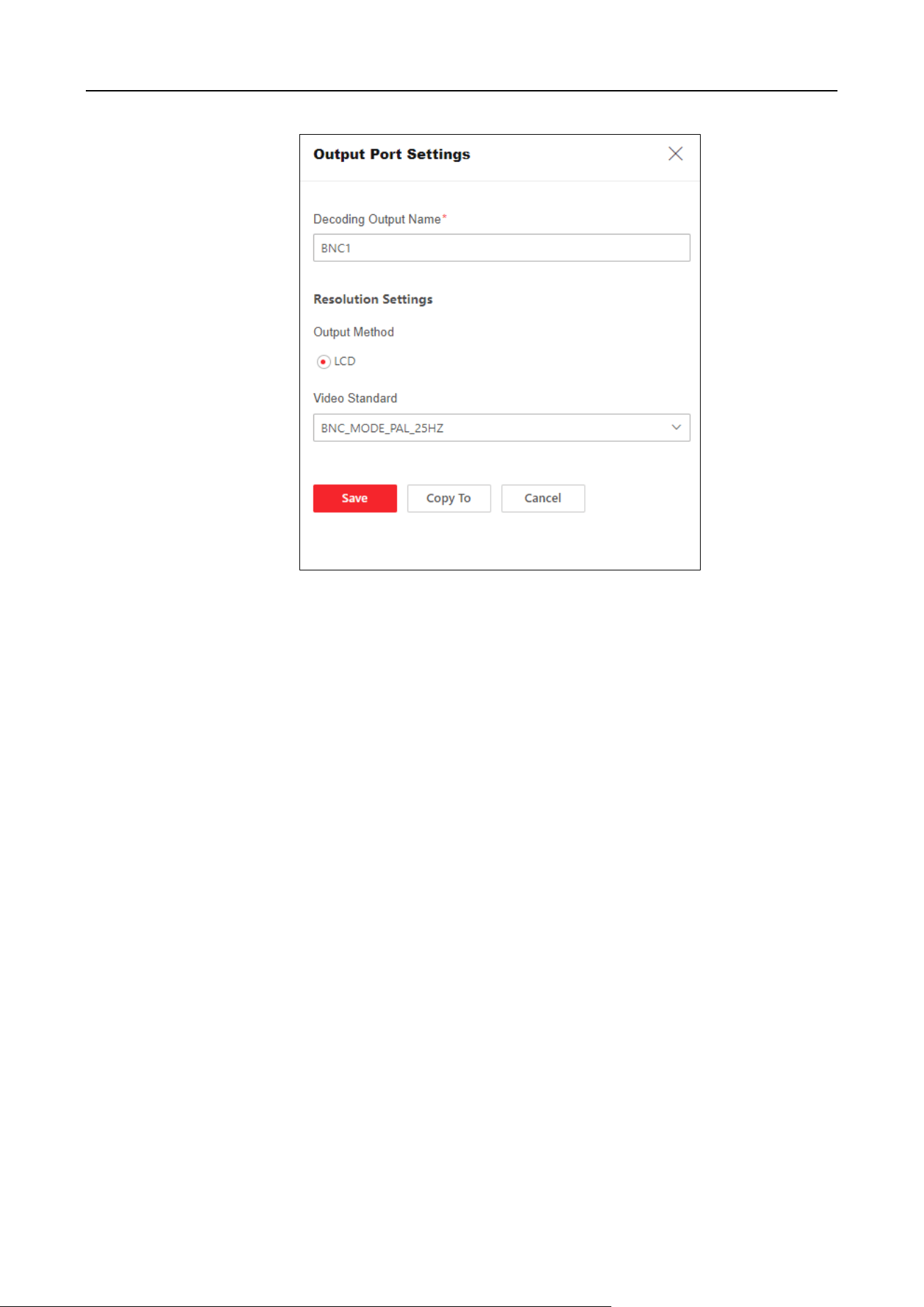
DS-6900UDI(C) Series Ultra HD Video and Audio Decoder • User Manual
5
Figure 2-6 BNC Output Port
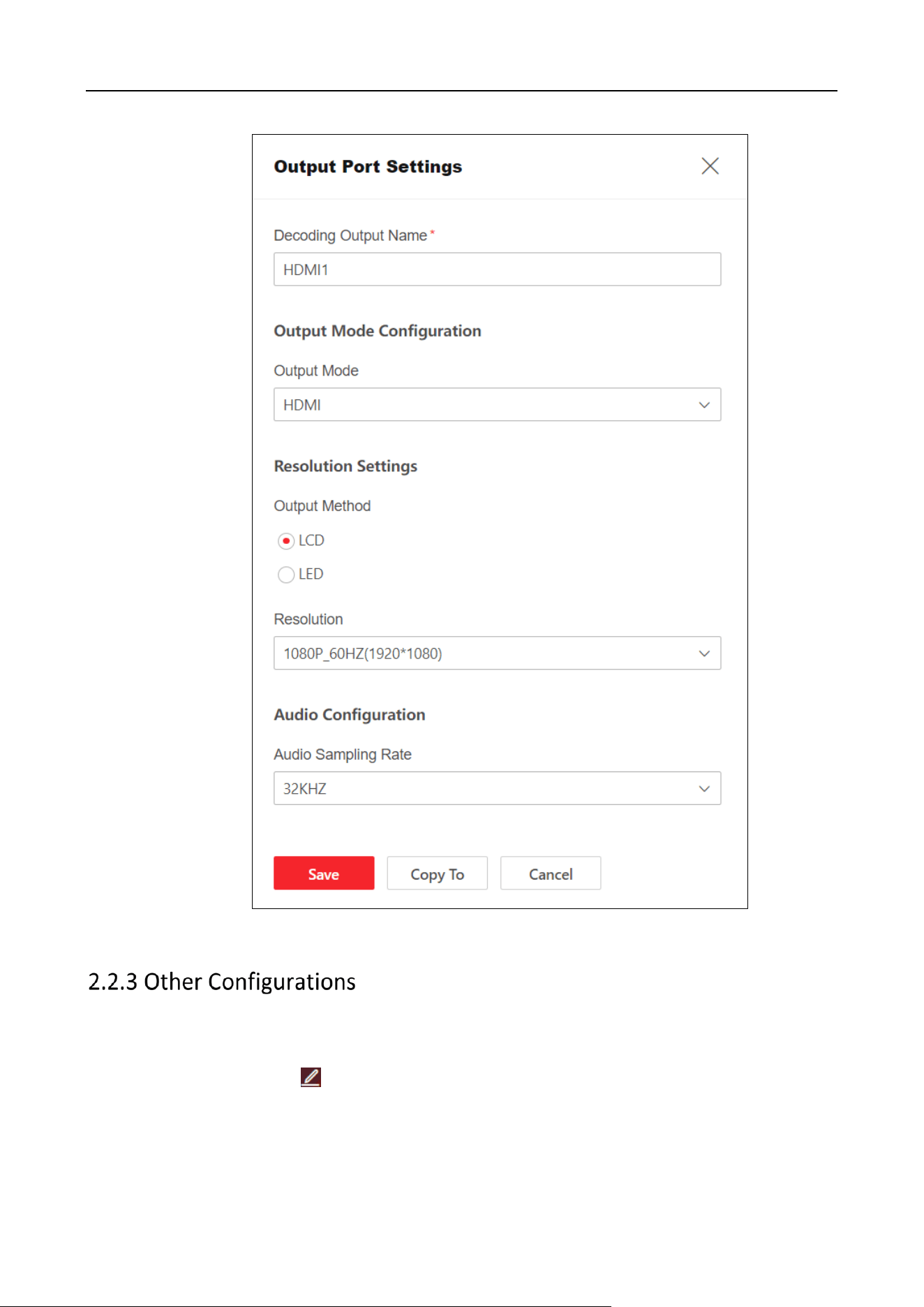
HDMI Output Port
Output Name: Customize a name.
Video Format: Select the output mode of the decoder connected to the display screen,
with options for HDMI and DVI. If the decoder is connected to the display screen and
uses HDMI output, the output mode can be set to HDMI.
Output Method: Select LCD based on the type of display screen connected to the
decoder.
Resolution: Set the resolution based on the display screen.
LCD: When selecting the LCD output method, select the LCD resolution according to the
requirement.
Audio Sampling Rate: Select according to actual needs.
Copy To: Copy the HDMI output port configuration to other decoders.
DS-6900UDI(C) Series Ultra HD Video and Audio Decoder • User Manual
6
Figure 2-7 HDMI Output Port
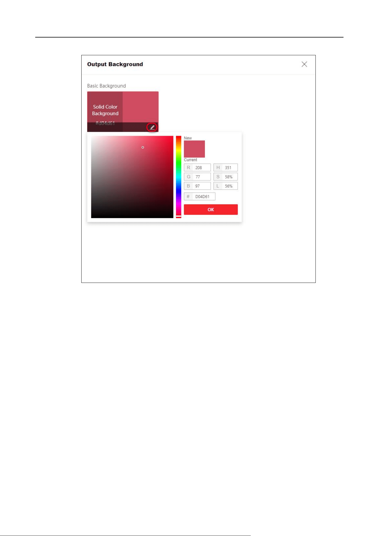
Edit Output Background
Edit the output background of the single video wall.
Click Output Background > in the lower right to edit the background color.
DS-6900UDI(C) Series Ultra HD Video and Audio Decoder • User Manual
7
Figure 2-8 Select Solid Color Background
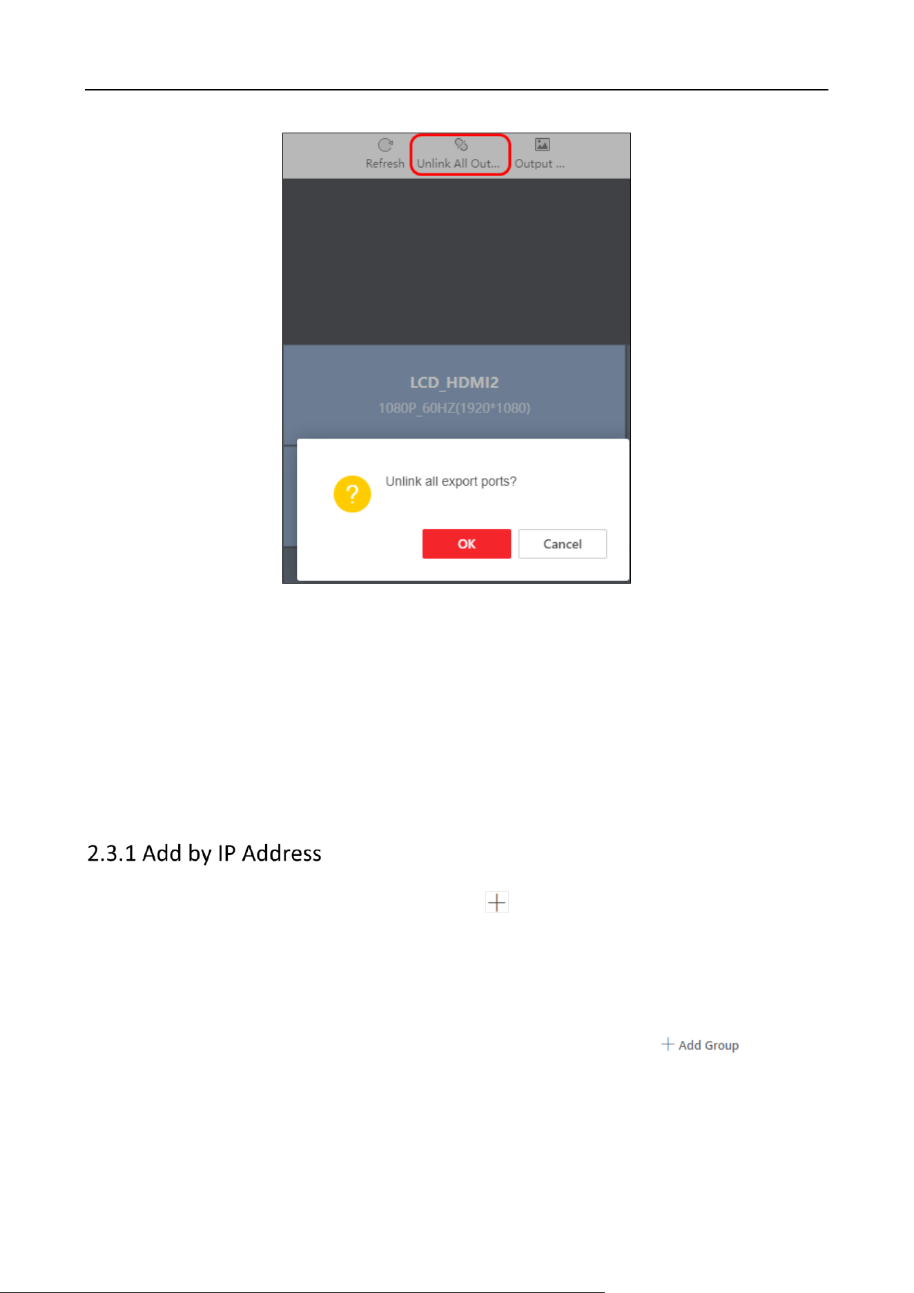
Unlink All Output Ports
Click Unlink All Output Ports, and click Save.
DS-6900UDI(C) Series Ultra HD Video and Audio Decoder • User Manual
8
Figure 2-9 Unlink All Output Ports
Display Output No.
Click Display Output No.to display the output No.
Refresh
Click Refresh to refresh the video wall configuration.
2.3 Network Signal Source Management
Signal source can be added by entering IP address or URL.
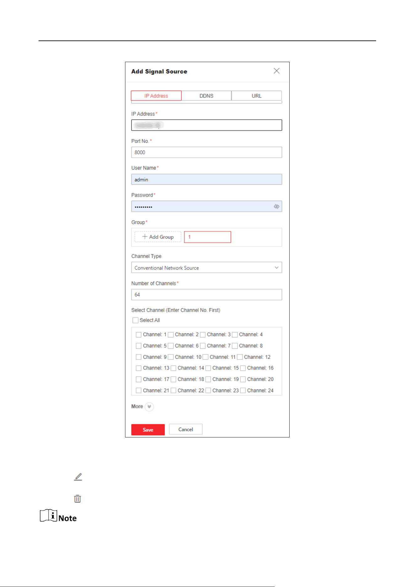
Step 1 Click Video Wall Operation > Signal Source > to select IP address.
Step 2 Fill in signal source information and stream media information.
Device Name: Enter a custom name.
IP Address and Port No.: Enter signal source address and port No..
User Name and Password: Enter user name and password of the signal source.
Group: Select the group for the signal source. You can also click to add a
new group.
Channel Type:

DS-6900UDI(C) Series Ultra HD Video and Audio Decoder • User Manual
9
Ordinary Network Source: Fill in the number of channels based on the number of channels
in the signal source, and check the channels that need to be added.
Zero Channel Network Source: No channel number needs to be set.
If the added signal source is NVR, the number of channels needs to be calculated starting from 33,
and the first 32 channels are reserved as analog channels. For example, to add a 32 channel NVR,
the number of channels needs to be set to 32 + 32=64.
Step 3 Click More to select transfer protocol, stream type, device manufacturer and stream IP
address.
Transfer Protocol: Support TCP and UDP.
Stream Type: Support main stream, sub-stream, and third stream.
Encrypted Stream: When Enabled, the stream can be encrypted, and a secret key needs
to be set at the same time.
Device Manufacturer: Select the manufacturer to which the signal source belongs.
Get Stream via Streaming Server: Enable according to the requirement, and set the stream
media IP address, port and transmission protocol simultaneously. Transfer real-time
preview data through streaming media servers to reduce network pressure.
DS-6900UDI(C) Series Ultra HD Video and Audio Decoder • User Manual
10
Figure 2-10 Add Signal Source by IP Address
Step 4 Click Save.
Step 5 (Optional) Perform the following operations.
Click to modify the information like Device Name, Transmission Protocol, Group, Getting
Stream via Stream Media of the Added Signal Source.
Click to delete the signal source that has already been added.
DS-6900UDI(C) Series Ultra HD Video and Audio Decoder • User Manual
11
If the network signal source has been decoded onto the video wall, editing or deleting is not
supported.
Step 1 Click Video Wall Operation > Signal Source > to select DDNS.
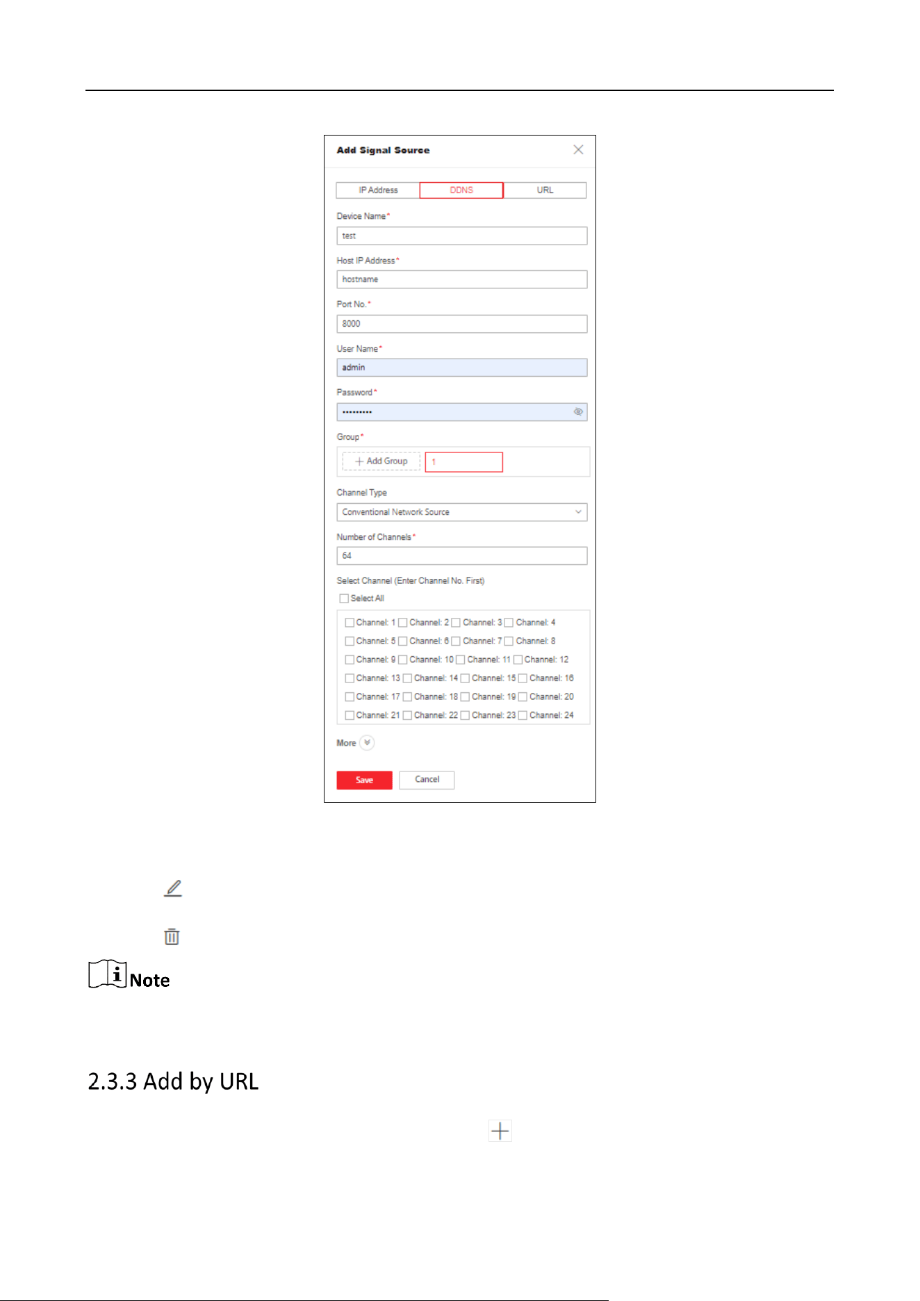
Step 2 Fill in signal source information and stream media information.
Device Name: Customized entering.
Host IP Address and Port No.: Entering signal source host IP address and port number.
User Name and Password: Entering user name and password of the signal source.
Group: Select the group of the signal source added. You can also click to
add a new group.
Channel Type:
Ordinary Network Source: Fill in the number of channels based on the number of channels
in the signal source, and check the channels that need to be added.
Zero Channel Network Source: No channel number needs to be set.
If the added signal source is NVR, the number of channels needs to be calculated starting from 33,
and the first 32 channels are reserved analog channels. For example, to add a 32 channel NVR, the
number of channels needs to be filled in as 32 + 32=64.
Step 3 Click More to select transfer protocol, stream type, device manufacturer and stream IP
address.
Transfer Protocol: Support TCP and UDP.
Stream Type: Support main stream, sub-stream, and third stream.
Encrypted Stream: When Enabled, the stream can be encrypted, and a secret key needs
to be set at the same time.
Device Manufacturer: Select the manufacturer to which the signal source belongs.
Get Stream via Streaming Server: Enable according to the requirement, and set the stream
media IP address, port and transmission protocol simultaneously.
Transfer real-time preview data through streaming media servers to reduce network
pressure.
DS-6900UDI(C) Series Ultra HD Video and Audio Decoder • User Manual
12
Figure 2-11 Add Signal Source by DDNS
Step 4 Click Save.
Step 5 (Optional) Perform the following operations:
Click to modify the information like Device Name, Transmission Protocol, Group, Getting
Stream via Stream Media of the Added Signal Source.
Click to delete the signal source that has already been added.
If the network signal source has been decoded onto the video wall, editing or deleting is not
supported.
Step 1 Click Video Wall Operation > Signal Source > to select URL.
DS-6900UDI(C) Series Ultra HD Video and Audio Decoder • User Manual
13
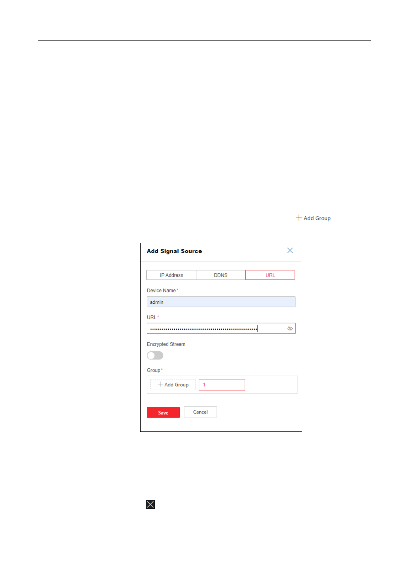
Step 2 Fill in signal source information and stream media information.
Device Name: Enter a custom name.
URL: Enter signal source URL.
The URL parameters are described as follows:
rtsp://IP:554/h264/ch1/main/av_stream/?username=admin?password=12345678?link
mode=tcp
For example
rtsp://192.0.0.1:554/h264/ch1/main/av_stream/?username=admin?password=
12345678?linkmode=tcp
Among them, 192.0.0.1 is the IP address of the signal source, admin is the user name,
12345678 is the password, and TCP is the streaming protocol (the streaming protocol
supports TCP, UDP)
Encrypted Stream: When enabled, the stream will be encrypted, and a secret key needs
to be set at the same time.
Group: Select the group for the signal source. You can also click to add a
new group.
Figure 2-12 Add by URL
Step 3 Click Save.
2.4 Video Wall Operation
Click Video Wall Operation to drag the signal source on the left to the output port on the right to
decode on the video wall. Click to stop the signal source from decoding onto the video wall.
DS-6900UDI(C) Series Ultra HD Video and Audio Decoder • User Manual
14
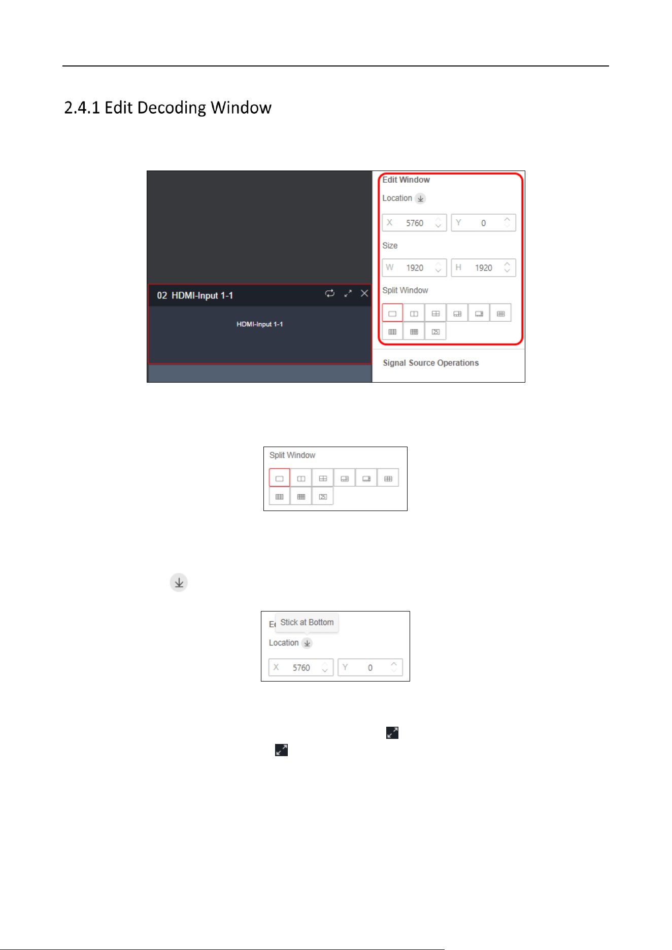
Click the decoding window to adjust the window position and size, and perform operations such as
splitting, roaming and enlarging window.
Figure 2-13 Edit Window
Split Window
Click the corresponding split screen icon to perform window splitting.
Figure 2-14 Split Window
Sticking Layer at Bottom
After decoding to the video wall, a layer will be displayed on the corresponding output port. Click
the layer and click to stick the layer at bottom.
Figure 2-15 Stick the Layer at Bottom
Roam and Enlarge Window
When roaming a window to multiple output ports, click to enlarge the window to cover the
occupied output ports, and then click to restore again.
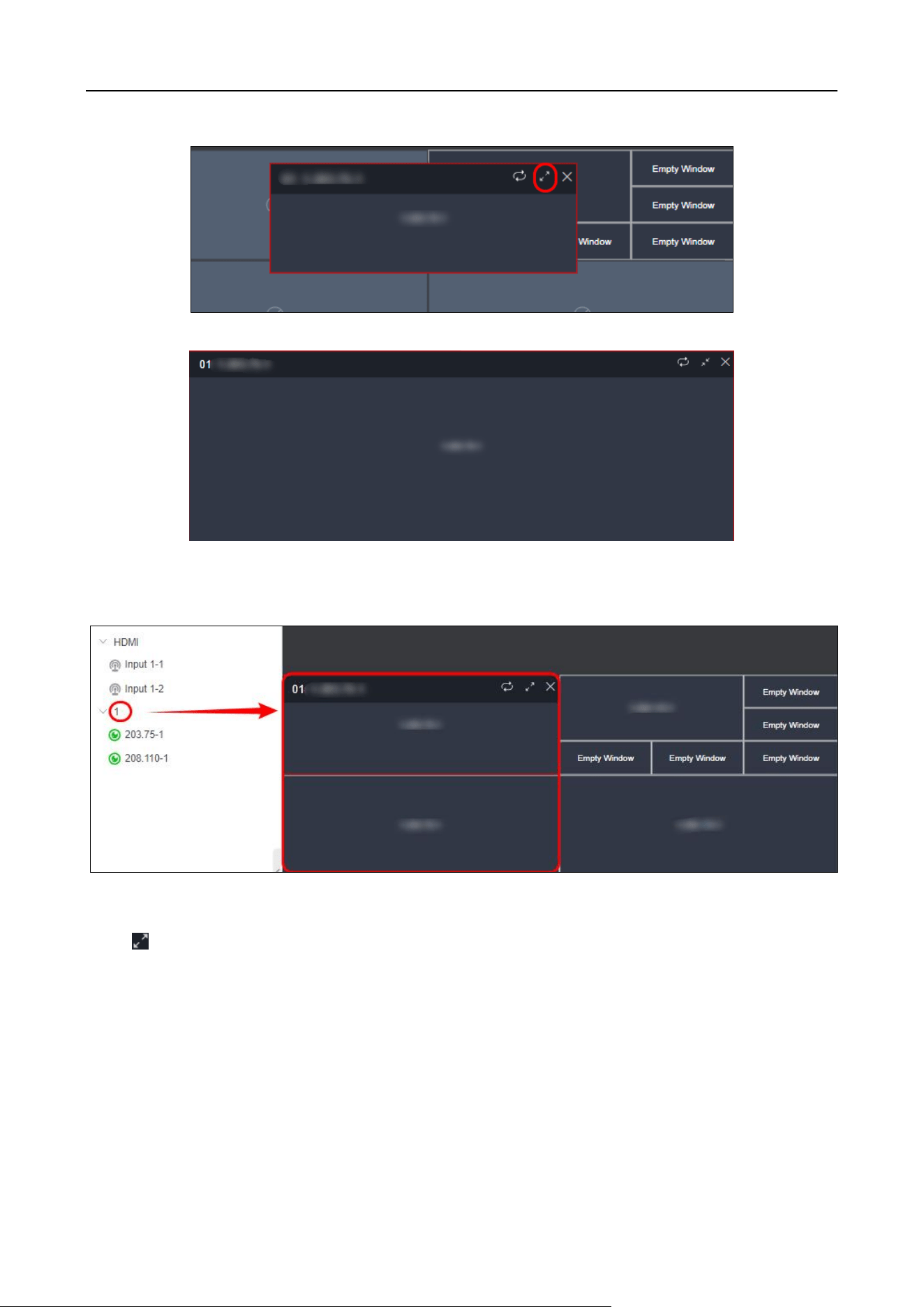
DS-6900UDI(C) Series Ultra HD Video and Audio Decoder • User Manual
15
Figure 2-16 Roam Window
Figure 2-17 Enlarge Window
Batch Open Windows
Directly drag the folder to the output port to batch open windows and decode to the video wall.
Figure 2-18 Batch Open Window
Start Signal Source Auto-Switch
Click to select the signal source and set the screen dwell time. Click Start Auto-Switch.
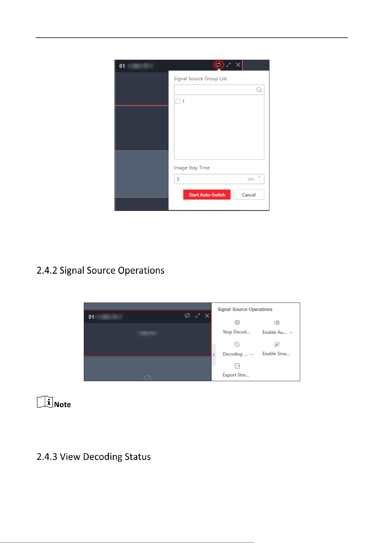
DS-6900UDI(C) Series Ultra HD Video and Audio Decoder • User Manual
16
Figure 2-19 Start Signal Source Auto-Switch
Clear Window
Click Clear to clear all windows of the signal source.
Click the decoding window to stop/start decoding, turn on/off audio, set decoding delay, and turn
on/off intelligent decoding for the signal source.
Figure 2-20 Decoding Status
After enabling intelligent decoding, the device can decode and display behavior information
detected by cameras.
You can view the decoding window No., decoding connection status, decoding status, picture width
and height, video frame rate, audio frame rate (sound needs to be turned on), stream transmission
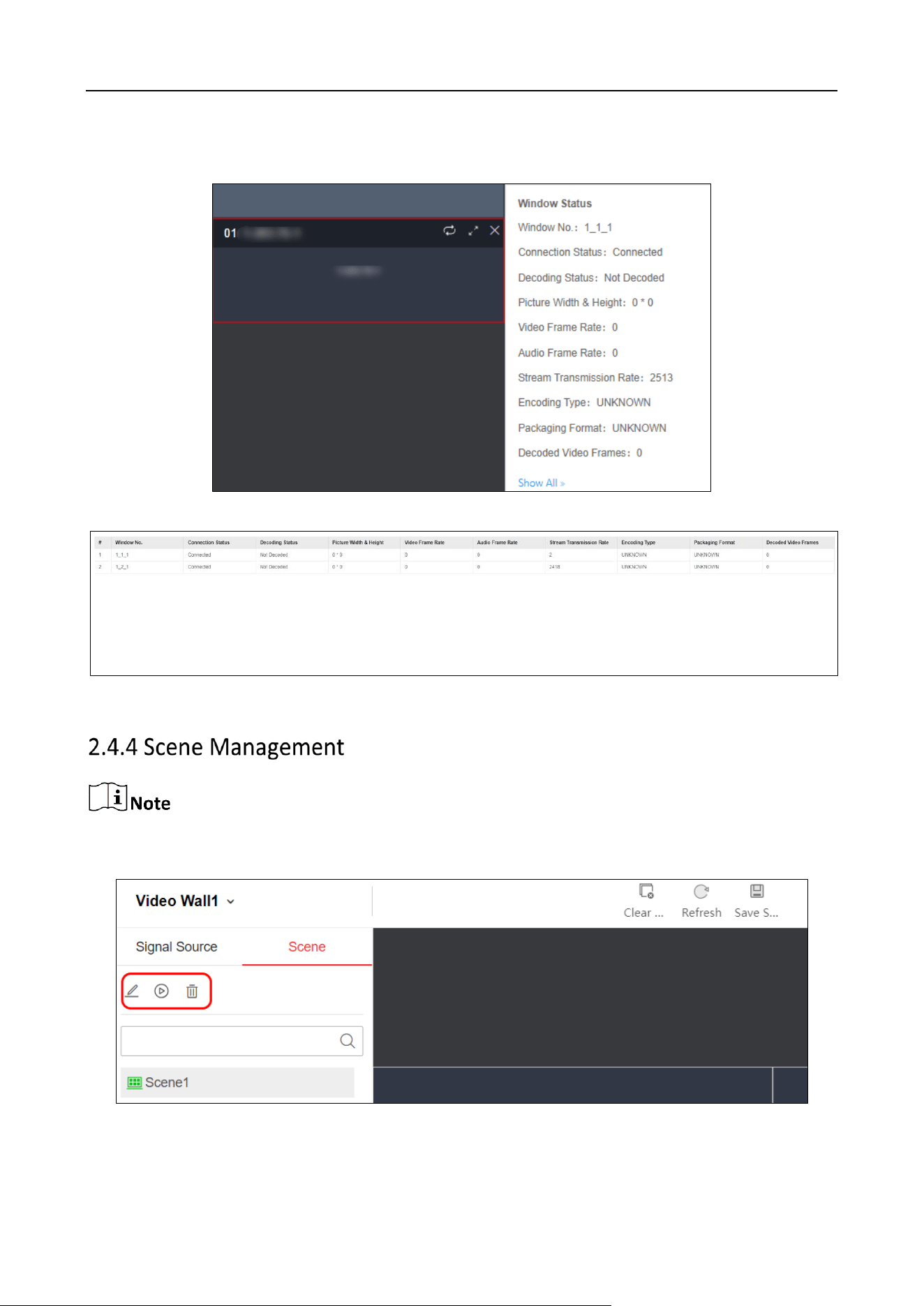
DS-6900UDI(C) Series Ultra HD Video and Audio Decoder • User Manual
17
rate, encoding type, packaging format, and decoded video frames. Click Show All to enter the
decoding status page.
Figure 2-21 Decoding Status Details
Figure 2-22 Decoding Status Page
No more than 64 scenes can be added for a device.
Click Video Wall Operation > Scene to edit, call and delete scenes.
Figure 2-23 Scene Management
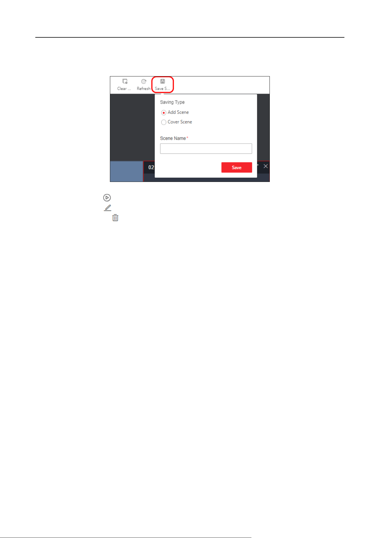
DS-6900UDI(C) Series Ultra HD Video and Audio Decoder • User Manual
18
Save Scene: Click Save Scene to save the current video wall scheme as a new scene or overwrite
the old scene.
Figure 2-24 Save Scene
Call Scene: Click to call the scene.
Edit Scene: Click to edit the scene name.
Delete Scene: Click to delete the scene.
DS-6900UDI(C) Series Ultra HD Video and Audio Decoder • User Manual
19
Chapter 3 General Configuration
3.1 System Configuration
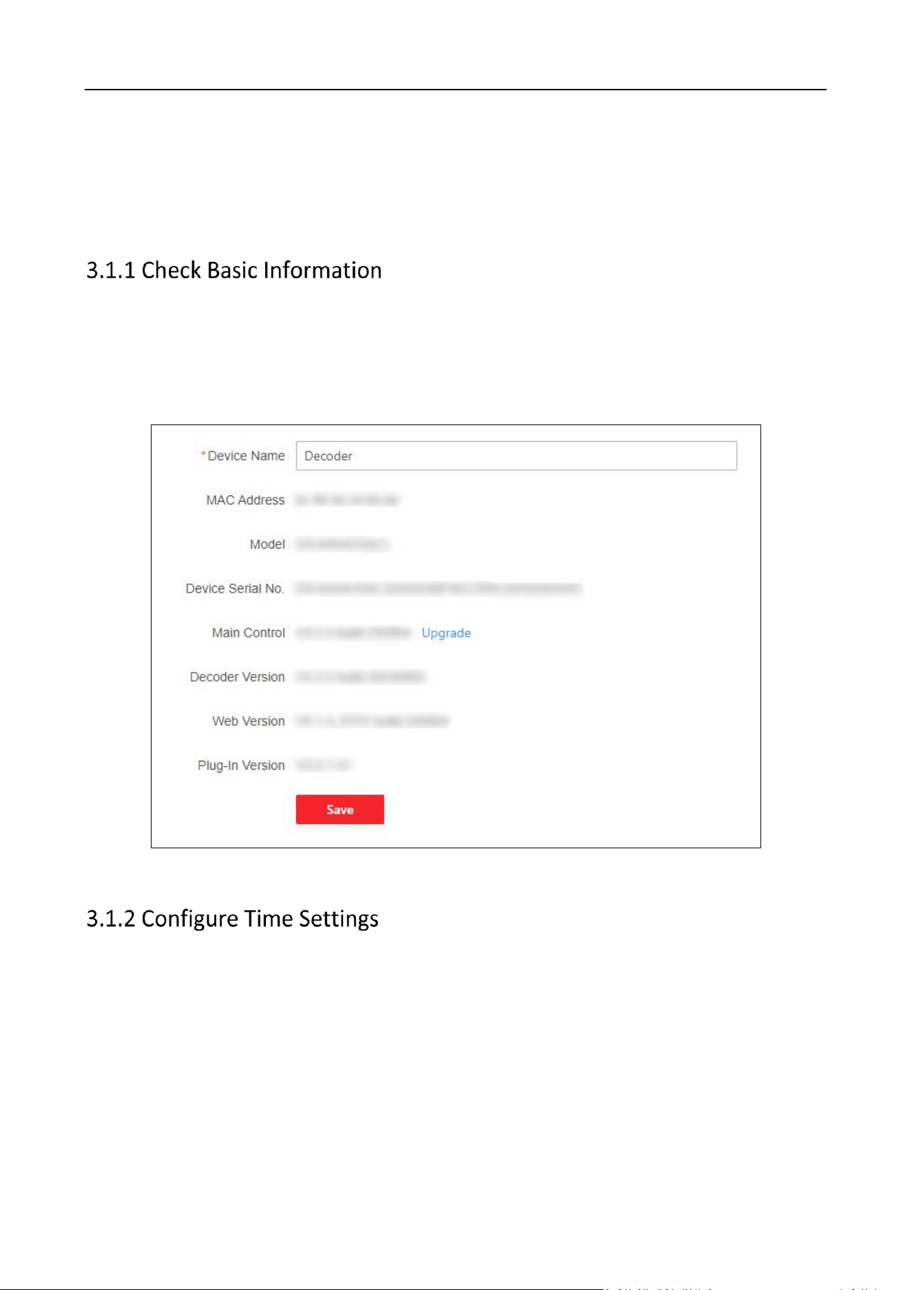
Click Configuration > System > System Settings > Basic Information.
You can check the device information, such as the device name, Mac address, model, device serial
No., main control version, etc.
You can edit the device name or click Upgrade to upgrade the main control.
Figure3-1 Basic Information
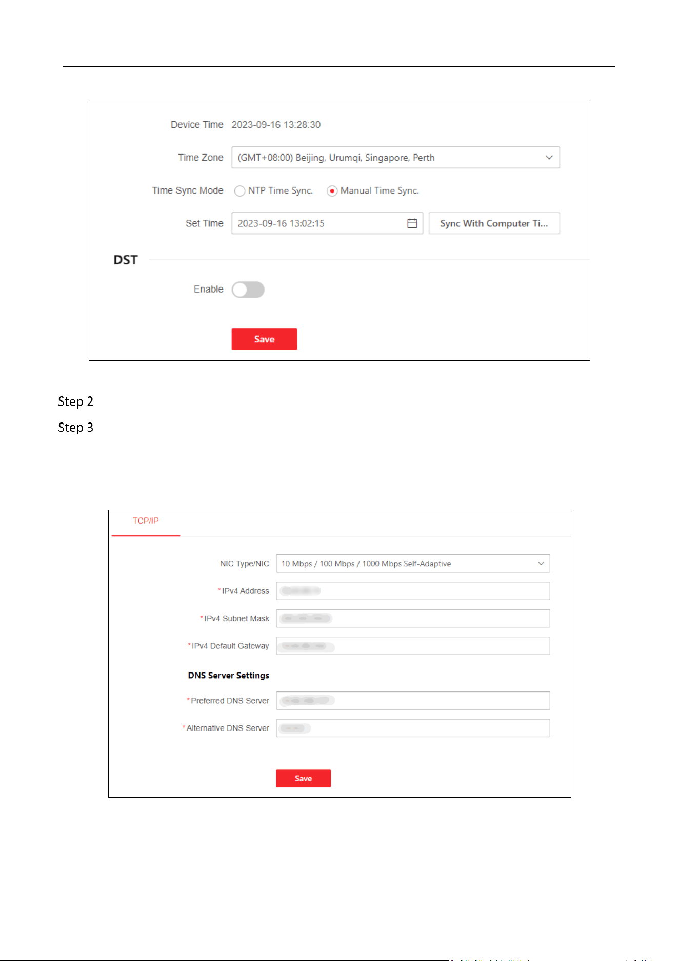
You can set the time zone, time synchronization mode, and time for the decoder, or enable the DST.
Step 1 Click Configuration > System Config. > Time Settings to enter the Time Setting page.
DS-6900UDI(C) Series Ultra HD Video and Audio Decoder • User Manual
20
Figure 3-2 Configure Time Settings
Step 2 Select a time zone.
Select a time synchronization mode and set the corresponding parameters.
Synchronize Time with NTP Server
Select NTP Time Sync., enter the IP address and port No. of NTP server, and select the
synchronization interval.
Figure 3-3 Configure Time by NTP
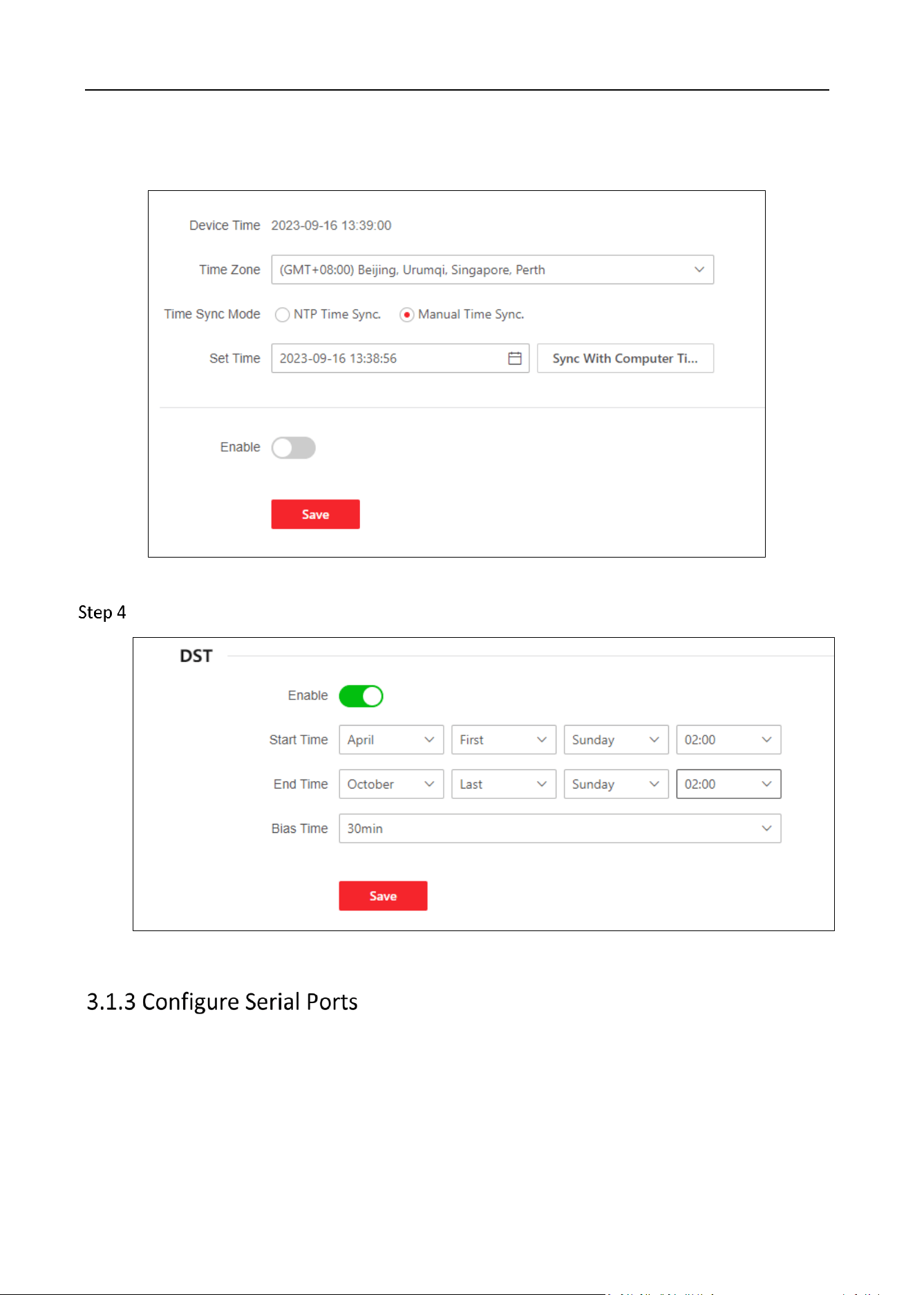
Synchronize Time Manually
DS-6900UDI(C) Series Ultra HD Video and Audio Decoder • User Manual
21
Select Manual Time Sync. and manually set the time for synchronization. You can also click Sync
With Computer Time and the system time will be synchronized with the computer time.
Figure 3-4 Configure Time Manually
(Optional)Enable the DST function and configure the start time, end time, and bias time.
Figure 3-5 DST Function Enabled
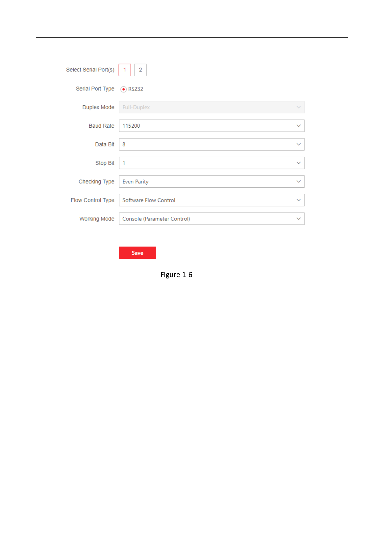
You can debug or control other products by serial ports settings.
Configure RS-232 Serial Port
Click Configuration > System > Serial Port Settings > Select Serial Port(s) 1 to enter the
following page and configure the serial port parameters
DS-6900UDI(C) Series Ultra HD Video and Audio Decoder • User Manual
22
Configure RS-232 Settings
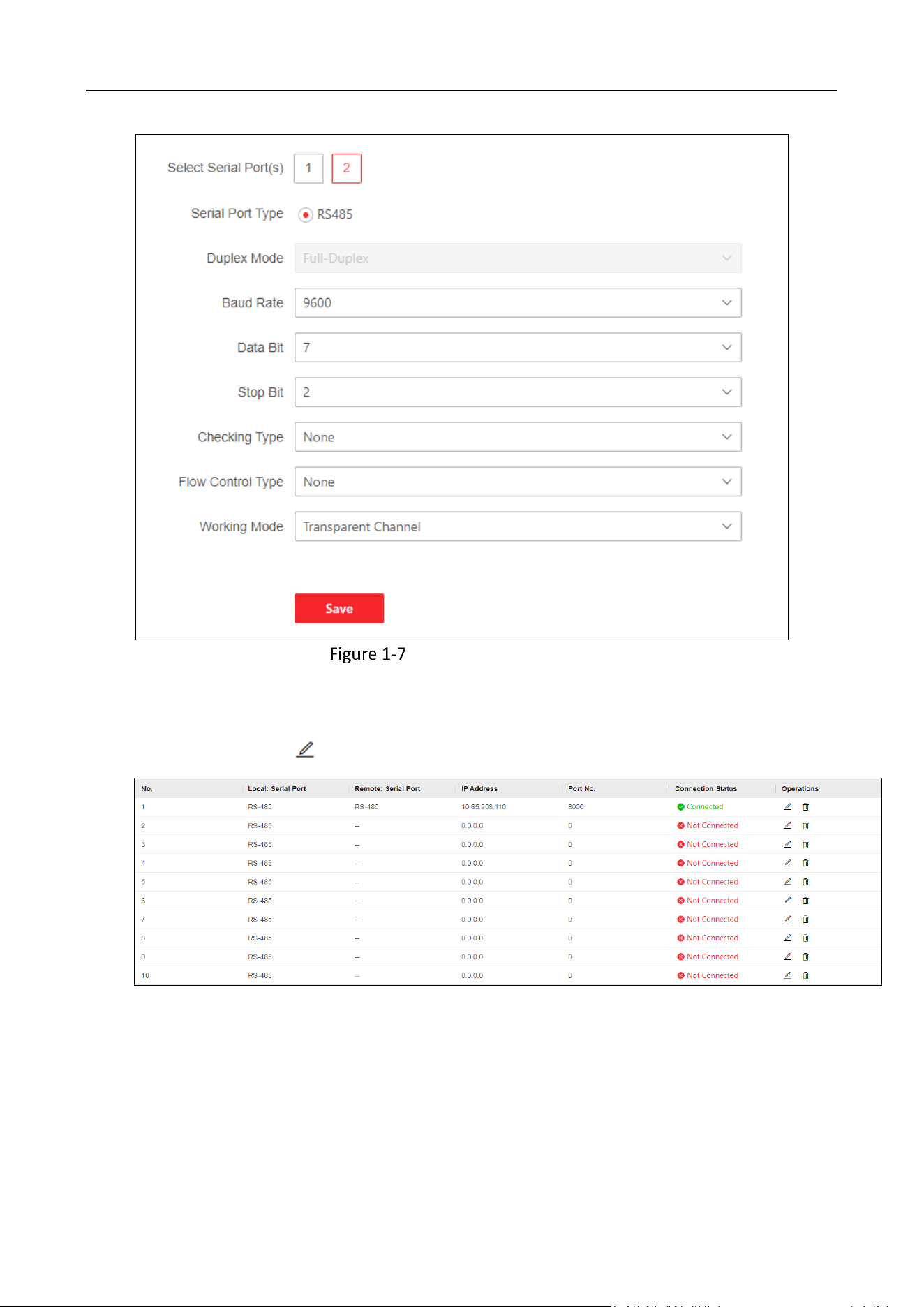
Configure RS-485 Serial Port
Click Configuration > System > Serial Port Settings > Select Serial Port(s) 2 to enter the
following page.
DS-6900UDI(C) Series Ultra HD Video and Audio Decoder • User Manual
23
Configure RS-485 Settings
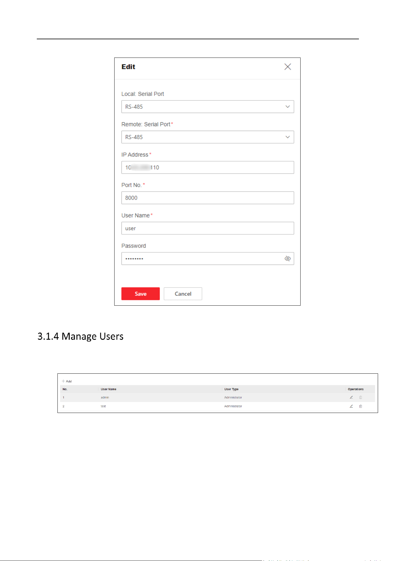
Configuring Transparent Channel
Click Configuration > System > Serial Port Settings > Transparent Channel to enter the
following page. Click to configure channel parameters.
Figure3-8 Select the Channel
DS-6900UDI(C) Series Ultra HD Video and Audio Decoder • User Manual
24
Figure3-9 Configure Channel Parameters
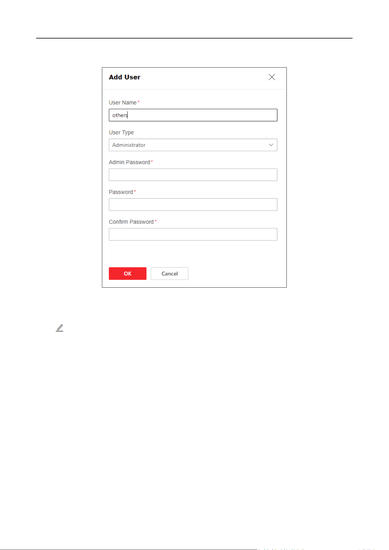
Click Configuration > System > User Management to enter the following page, which
supports adding, editing, and deleting user accounts.
Figure3-10 User Management
Add User Accounts
Click Add to fill in the user name, admin password, password, and confirm password.
DS-6900UDI(C) Series Ultra HD Video and Audio Decoder • User Manual
25
Figure 3-11 Add User Accounts
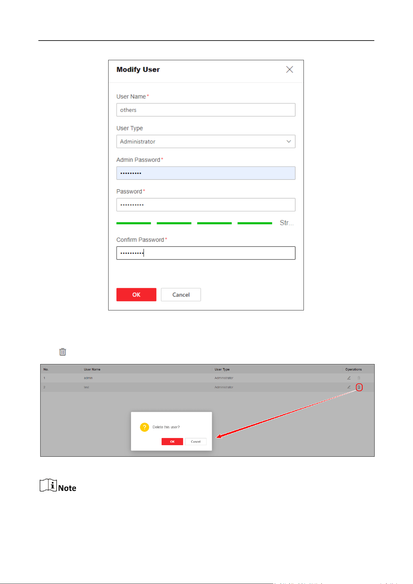
Edit User Name or Change Password
Click to edit the user name or change password.
DS-6900UDI(C) Series Ultra HD Video and Audio Decoder • User Manual
26
Figure 3-12 Edit User Information
Delete User Accounts
Click to delete the user account and click OK.
Figure 3-13 Delete User Accounts
Only the admin password can be changed. The name of admin user cannot be edited and the
admin user cannot be deleted.
DS-6900UDI(C) Series Ultra HD Video and Audio Decoder • User Manual
27
3.2 Network Configuration
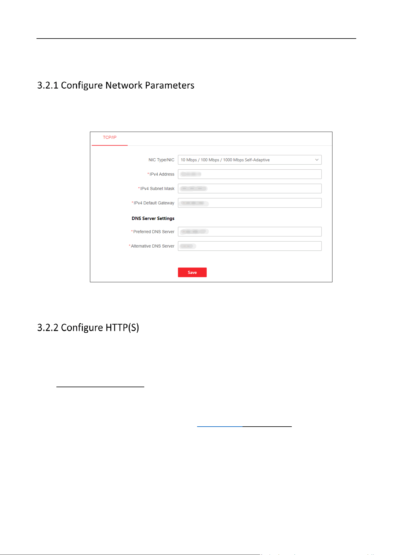
Step 1 Click Configuration > Network > Network Settings > TCP/IP to configure network
parameters, such as the IPv4 address, IPv4 subnet mask, IPv4 default gateway, and the IP
addresses of preferred and alternative DNS server.
Figure 3-14 Configure Network Parameters
Step 2 Click Save.
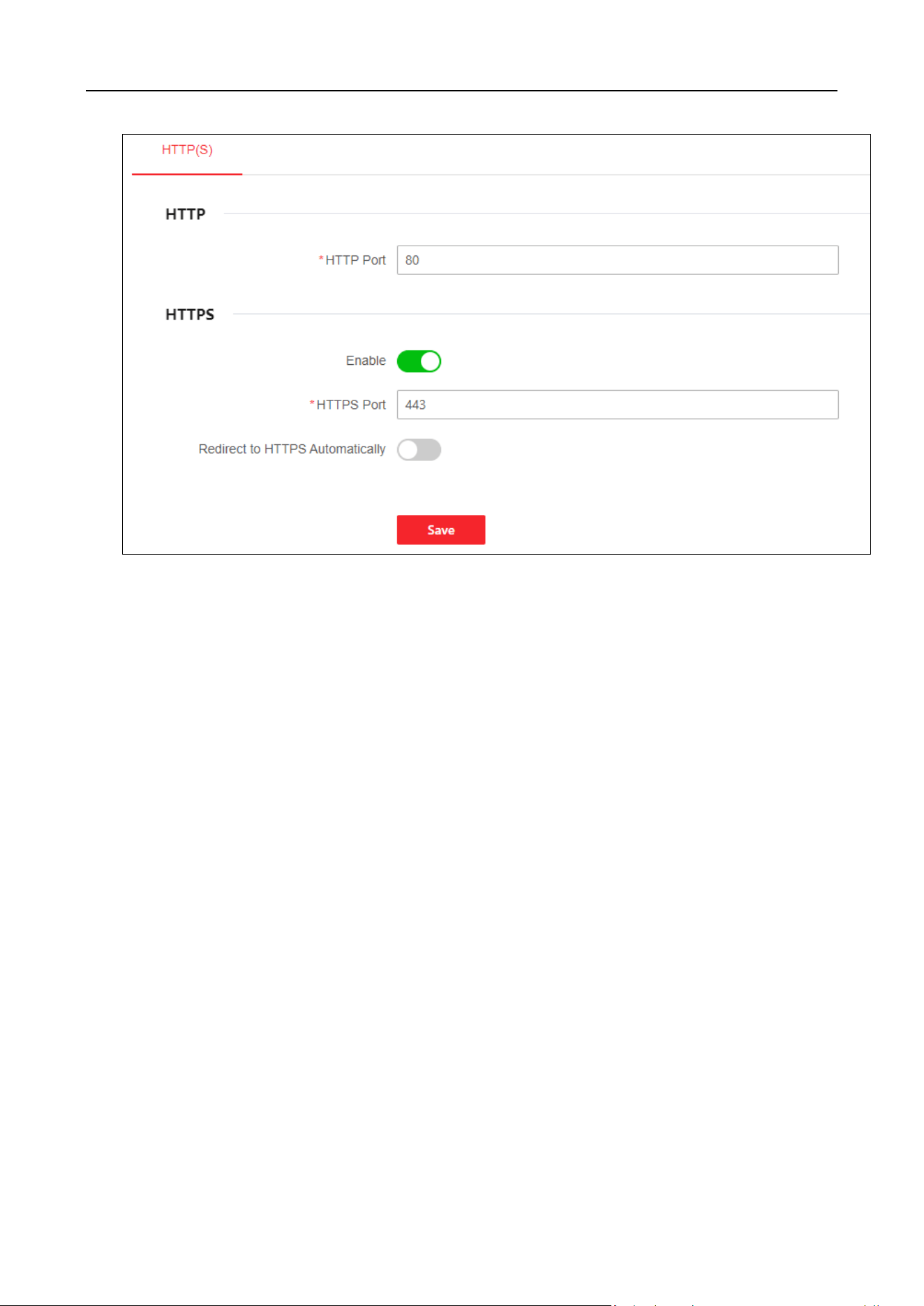
Step 1 Click Configuration > Network > Network Services > HTTP(S) to enter the following page.
HTTP Port
The port for the browser to access the device. When the HTTP port is changed to 81, you need to
enter http://Device IP Address:81 on the browser address bar.
Enable HTTPS
Use HTTPS to access the device while setting the HTTPS port. When editing the HTTPS port to 443
and logging in using a browser, you need to enter https://Device IP Address:443 on the browser
bar.
Redirect to HTTPS Automatically
If enabled, HTTPS will be used by default when accessing the device.
DS-6900UDI(C) Series Ultra HD Video and Audio Decoder • User Manual
28
Figure 3-15 Configure HTTP(S)
Step 2 Click Save.
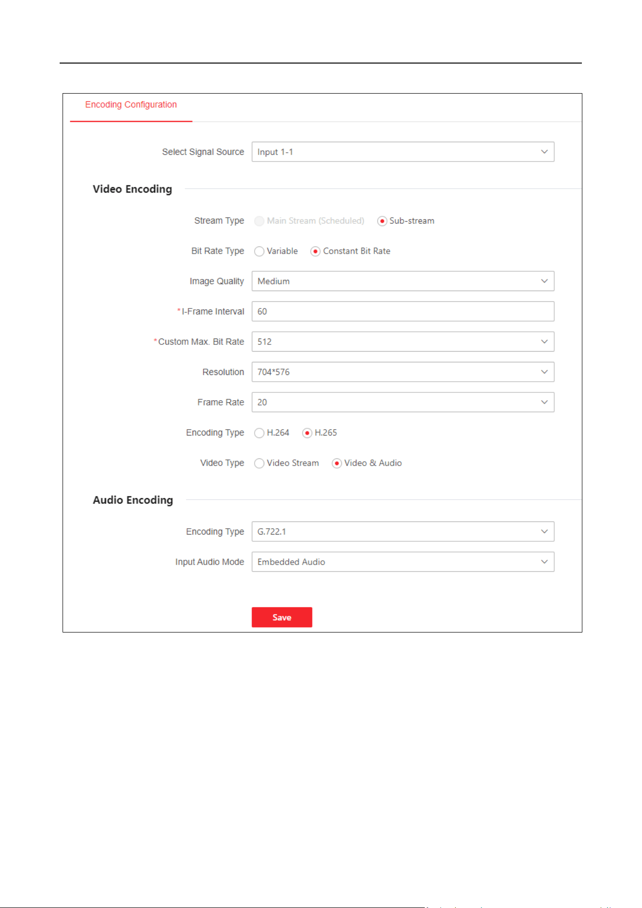
3.3 Configure Encoding Devices
Click Configuration > Signal Source Configuration > Encoding Configuration to set video encoding
parameters such as stream type and resolution.
Select Signal Source: Select the signal source that requires encoding parameters.
Stream Type: Sub-stream, which is used for standard definition storage and live view in case of
insufficient bandwidth.
Bit Rate Type and Max. Bit Rate: Bit rate type can be set to variable or constant bit rate.
Constant bit rate: Maintain the average bit rate for transmission with fast compression speed,
which may cause video mosaic phenomenon.
Variable bit rate: Adjust the bit rate on the basis of not exceeding the upper limit of the bit
rate with relatively slow compression speed, but able to ensure image clarity in complex
scenes.
Image Quality: Select according to the requirement of image clarity. The higher the image
quality, the higher the bandwidth requirement for the network.
I-Frame Interval: I-Frame Interval is the amount of frames between two continuous I-Frames.
The larger the frame interval, the smaller the fluctuation of the bit stream, but the image

DS-6900UDI(C) Series Ultra HD Video and Audio Decoder • User Manual
29
quality is relatively low. On the contrary, the larger the fluctuation of the bit stream, the higher
the image quality.
Resolution: Select according to the actual requirement for video clarity. The higher the
resolution, the higher the bandwidth requirement for the network.
Frame Rate: Refers to the number of frames per second in a video. Based on the actual
bandwidth situation, the higher the video rate, the higher the required bandwidth and storage
space.
Encoding Type: The encoding standard for the bit stream can be selected.
Video Type: You can choose between video stream and composite stream, which includes
video stream and audio stream.
Audio Encoding Type: Select the encoding standard for audio.
DS-6900UDI(C) Series Ultra HD Video and Audio Decoder • User Manual
30
Figure 3-17 Encoding Configuration
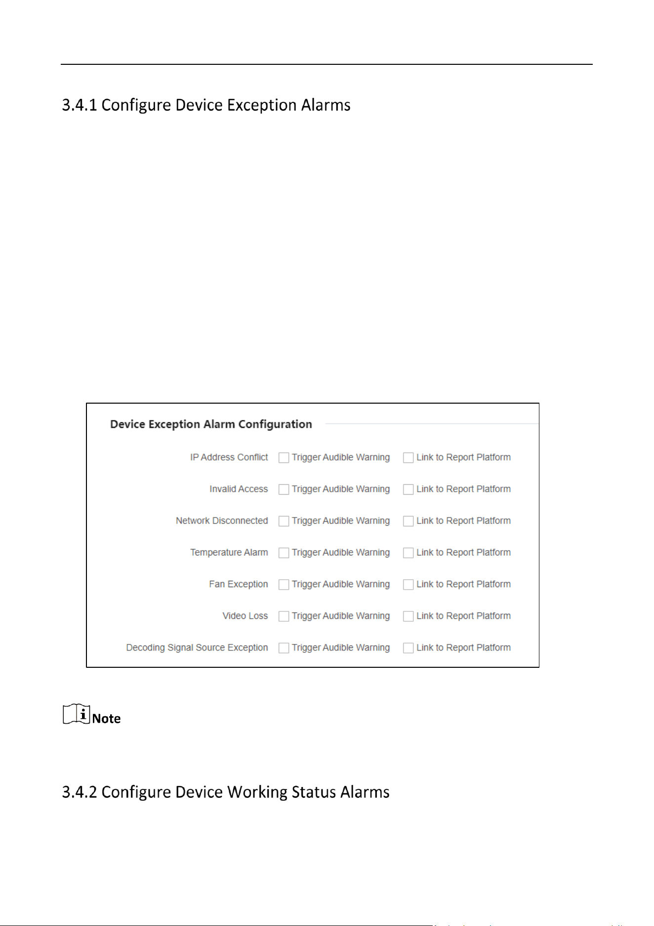
3.4 Event Configuration
When detecting incidents such as IP address conflicts, invalid access, network disconnection, and
temperature alarm, you can configure whether triggering the audible alarm and linking to report
platform or not.
Click Configuration > Event. All abnormal events support triggering the audible alarm and linking
to report platform
DS-6900UDI(C) Series Ultra HD Video and Audio Decoder • User Manual
31
IP Address Conflict: When the IP address of a device is the same as that of other devices in the
network, an alarm will be triggered and uploaded to the platform.
Invalid Access: It indicates that when entering an incorrect user name or password, an alarm
will be triggered and uploaded to the platform.
Network Disconnected: When the network of device is disconnected, an alarm will be
triggered and uploaded to the platform.
Temperature Alarm: When the temperature of device is too high or too low, an alarm will be
triggered and uploaded to the platform.
Fan Exception: It indicates that when the fan status is abnormal, an alarm will be triggered and
uploaded to the platform.
Video Loss: It indicates that when a video is lost, an alarm will be triggered and uploaded to
the platform.
Decoding Signal Source Exception: When the decoding signal source is abnormal, an alarm will
be triggered and uploaded to the platform.
Figure 3-18 Configure Device Exception Alarms
Multi-channel devices support abnormal fan status and video loss alarm, refer to the actual
capacity of the device for details.
DS-6900UDI(C) Series Ultra HD Video and Audio Decoder • User Manual
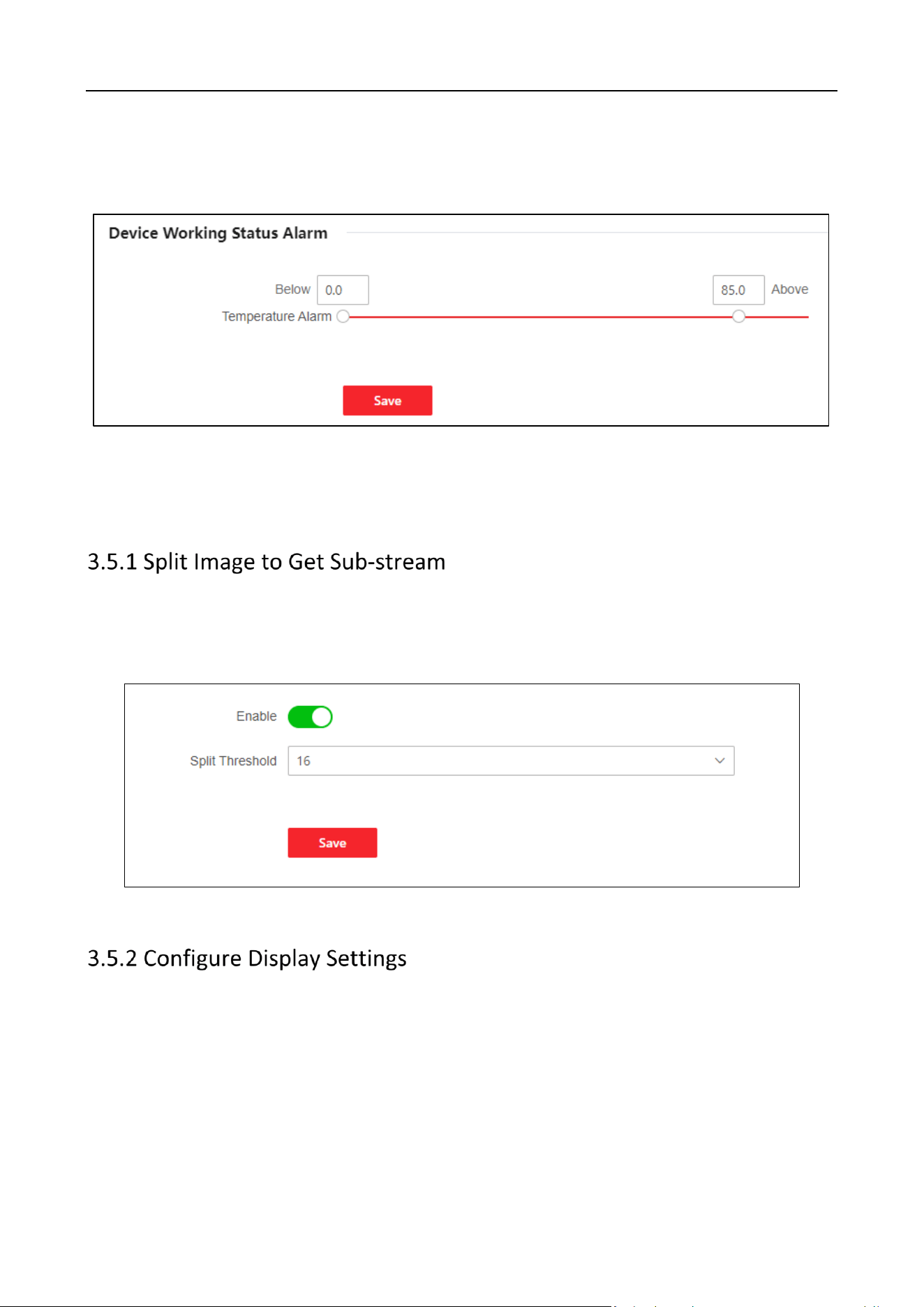
32
Set the maximum and minimum temperature thresholds for devices when they are working
normally. When the device temperature is higher than the maximum threshold or lower than the
minimum threshold, an alarm will be triggered and uploaded to the platform.
Figure 3-19 Configure Device Working Status Alarm
3.5 Other Settings
Click Configuration > Other Settings > Split Image to Get Sub-stream to enable the function and
set the split threshold.
When the threshold approaches, the image will automatically switch to sub-stream.
Figure 3-20 Split Threshold Configuration
Configure display settings when stopping decoding images, getting stream failed, and the decoding
resource is insufficient.
Click Configuration > Other Settings > Display Settings to configure parameters of display settings.
Stop Decoding Images: Select Black or Last Frame.
Image of Getting Stream Failed: Select Connection Exception or Last Frame.
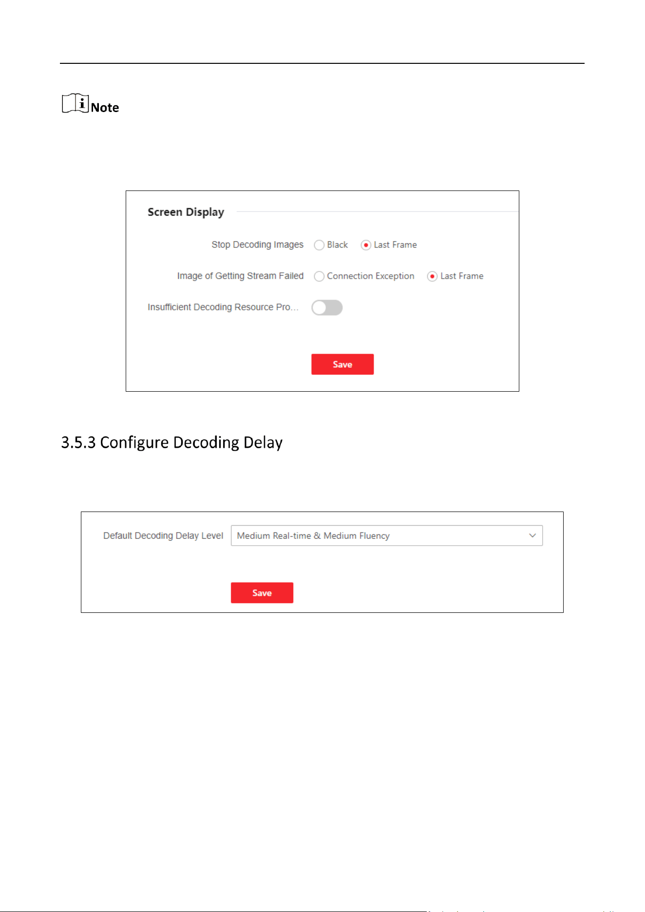
DS-6900UDI(C) Series Ultra HD Video and Audio Decoder • User Manual
33
If you select connection exception, the concrete reason will be displayed.
Insufficient Decoding Resource Prompt: Enable the button to prompt insufficient decoding
resource.
Figure 3-21 Screen Display Configuration
Configure the preference for real-time or fluency when decoding.
Click Configuration > Other Settings > Decoding Delay to select default decoding delay level.
Figure 3-22 Decoding Delay Level
DS-6900UDI(C) Series Ultra HD Video and Audio Decoder • User Manual
34
Chapter 4 Maintenance and Security
4.1 System Maintenance
Click Maintenance and Security > System Maintenance > Reboot. Click Reboot to reboot the
device.
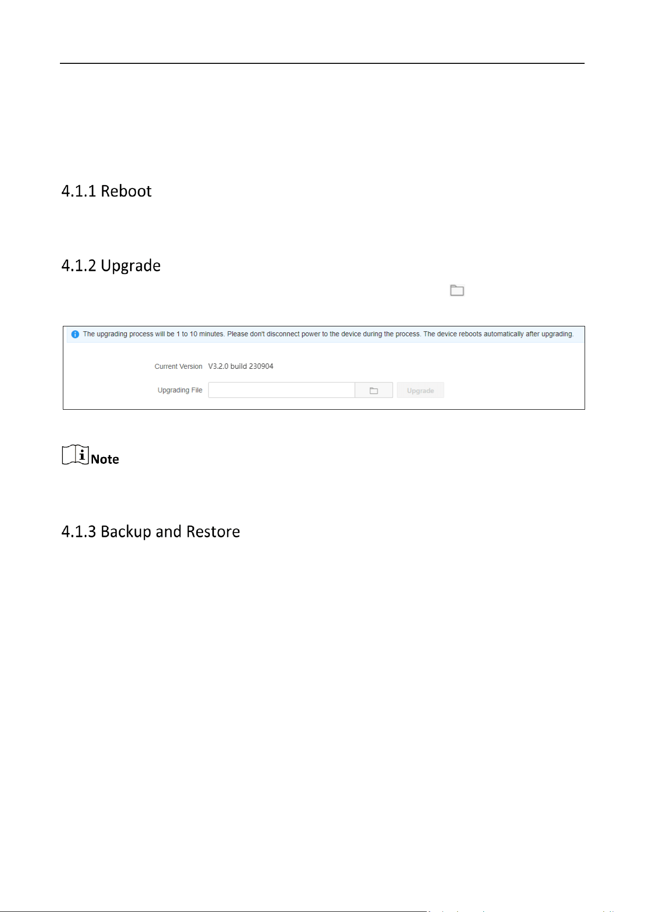
Click Maintenance and Security > System Maintenance > Upgrade. Click to select upgrading
files. Click Upgrade.
Figure 4-1 Upgrade
You need to acquire the upgrading files previously and save it in the local directory. Do not power
off in the process of upgrading. The devices will automatically reboot after upgrading.
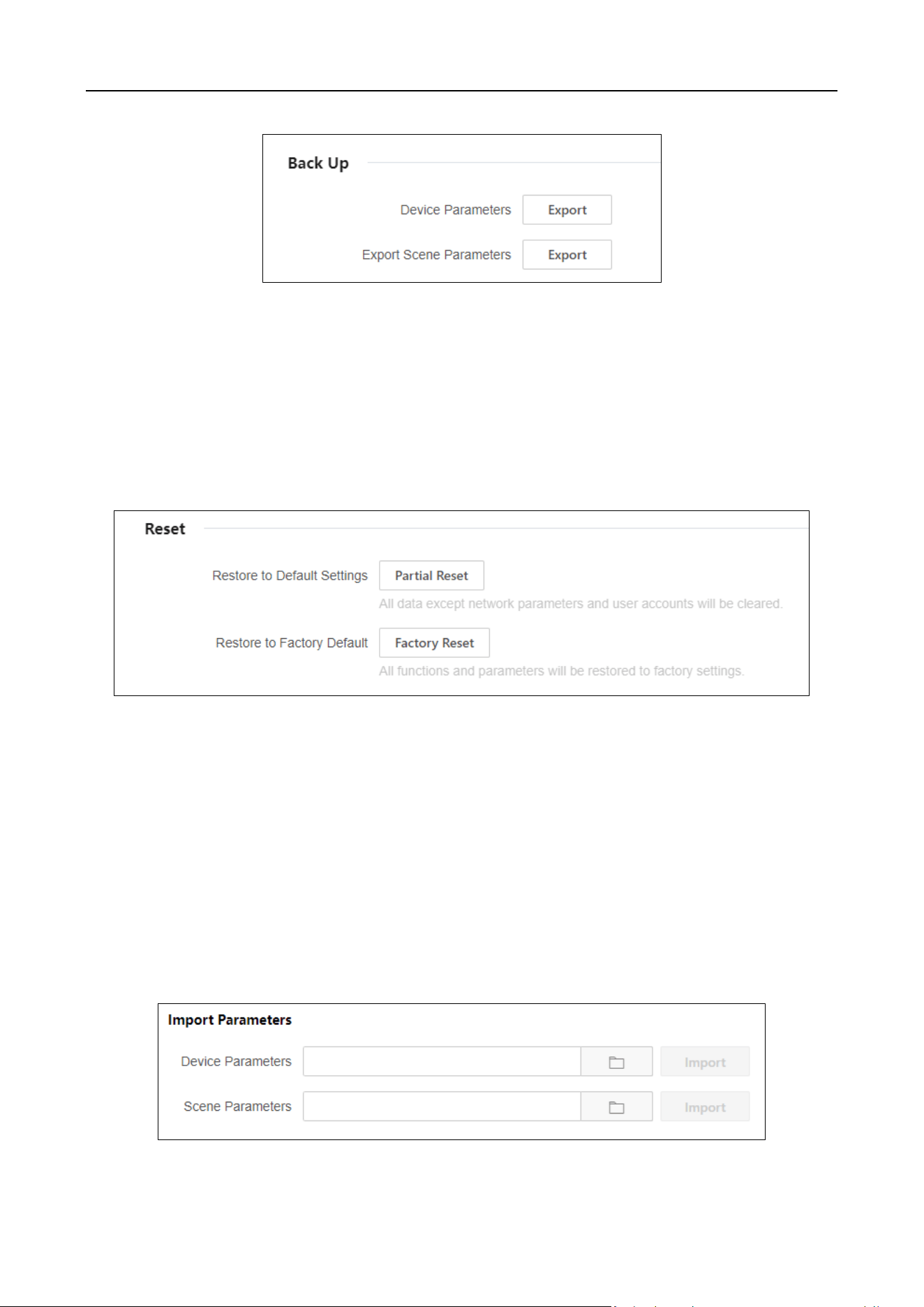
Click Maintenance and Security > System Maintenance > Backup and Restore to perform
operations such as importing/exporting parameters and restoring to default settings.
Export Parameters
Export device and scene parameters to quickly import the exported parameters into other devices.
Export Device Parameters
By exporting device parameters for the convenience of configuring other devices with the same
parameters.
Export Scene Parameters
By exporting the scene parameters for the convenience of configuring other devices with the same
parameters.
DS-6900UDI(C) Series Ultra HD Video and Audio Decoder • User Manual
35
Figure 4-2 Back Up
Reset
Partial Reset
All data except network parameters and user accounts will be cleared.
Factory Reset
All functions and parameters will be restored to factory settings.
Figure 4-3 Reset
Import Parameters
Import parameters that are exported from other devices to quickly use the same configuration.
Import Device Parameters
Import configured parameters that are exported from other devices to quickly use the same
parameters configuration.
Import Scene Parameters
Import scene parameters that are exported from other devices to quickly use the same scene
parameters configuration.
DS-6900UDI(C) Series Ultra HD Video and Audio Decoder • User Manual
36
Figure 4-4 Import Parameters
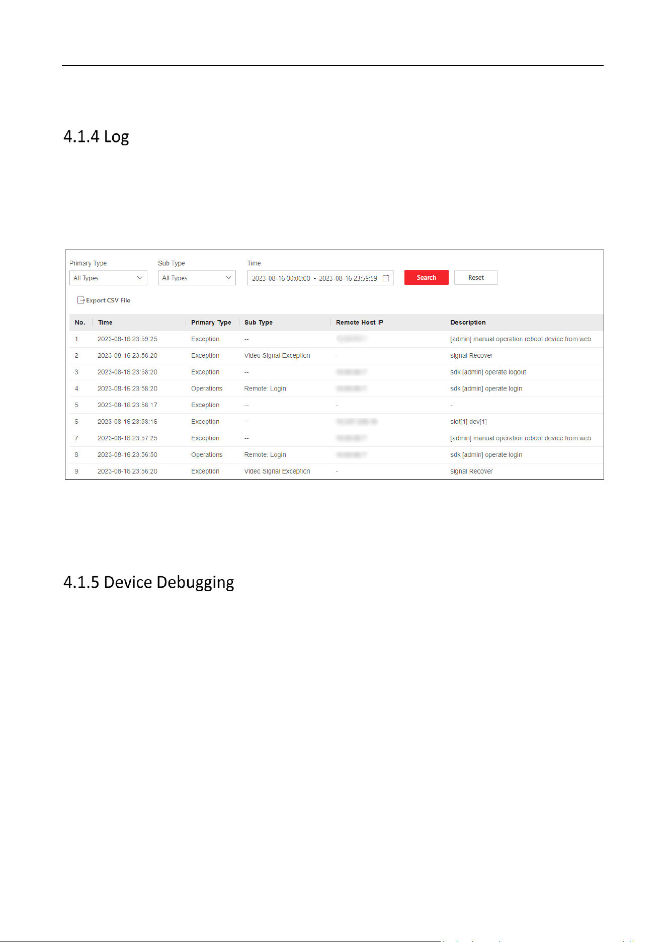
Search and export logs.
Search Logs
Click Maintenance and Security > System Maintenance > Log to set search conditions. Click
Search.
Figure 4-5 Log
Export Logs
Click Export CSV File to export log files in the CVS format.
Click Maintenance and Security > System Maintenance > Device Debugging.
SSH
Once enabled, remote devices can be accessed through SSH.
Export Logs to USB Drive
You can export device logs to a FAT32 USB drive, which requires formatting before inserting it into
the drive.
Export Network Switching Packet
Select a partition and click Start Capturing to capture network packet. Click Download to export
the captured content.
Shell Command Operation
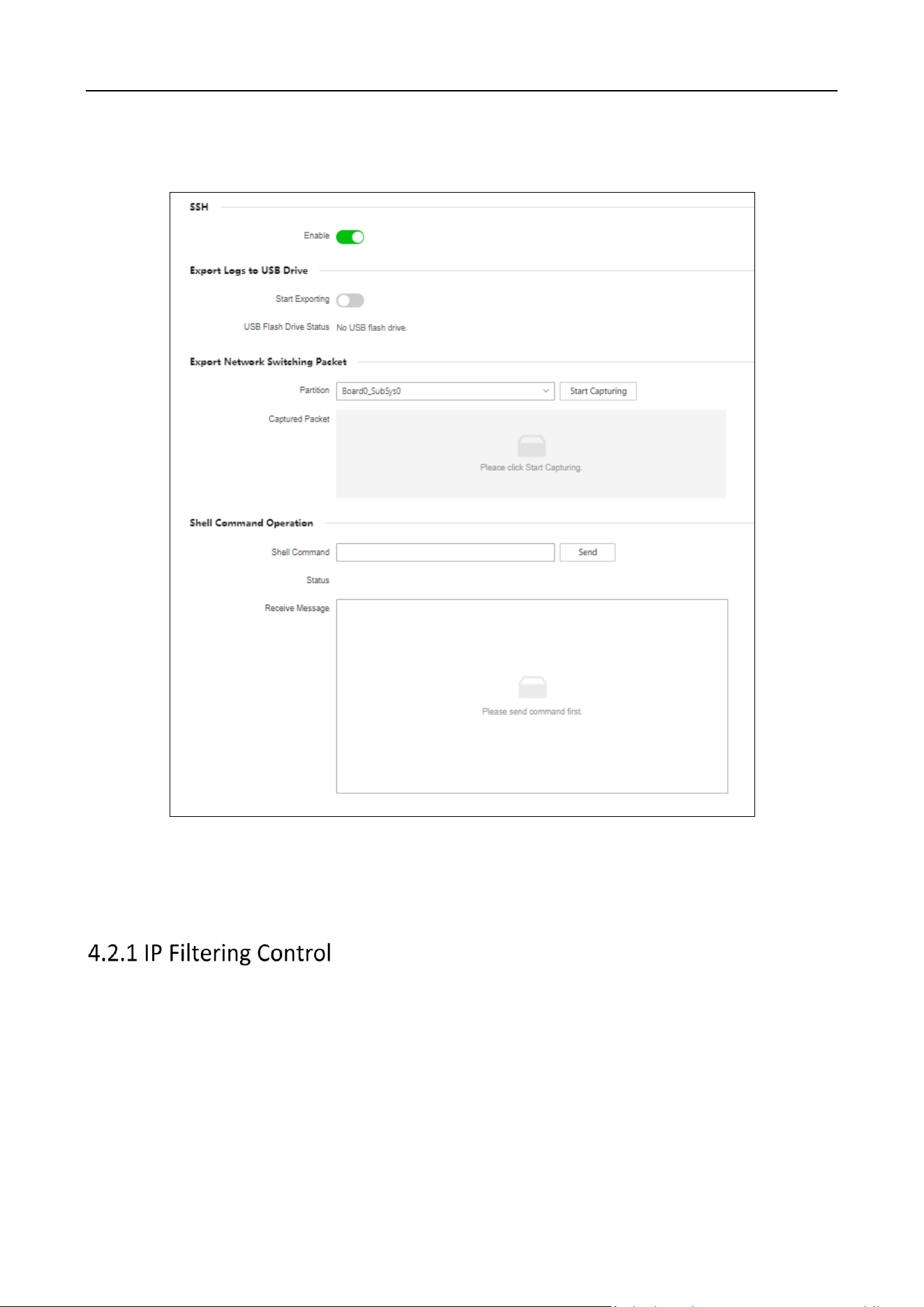
DS-6900UDI(C) Series Ultra HD Video and Audio Decoder • User Manual
37
Enter the Shell command, click Send and determine the abnormal situation of the device by
checking for received message.
Figure 4-6 Device Debugging
4.2 Security Management
Configure IP addresses that are allowed or prohibited to access the device.
Step 1 Click Maintenance and Security > Security Maintenance > IP Filtering Control to enable the
function.
Step 2 Select Filtering Type.
Blocklist: You are prohibited to access the device with the IP address.
Allowlist: You are allowed to access the device with the IP address.
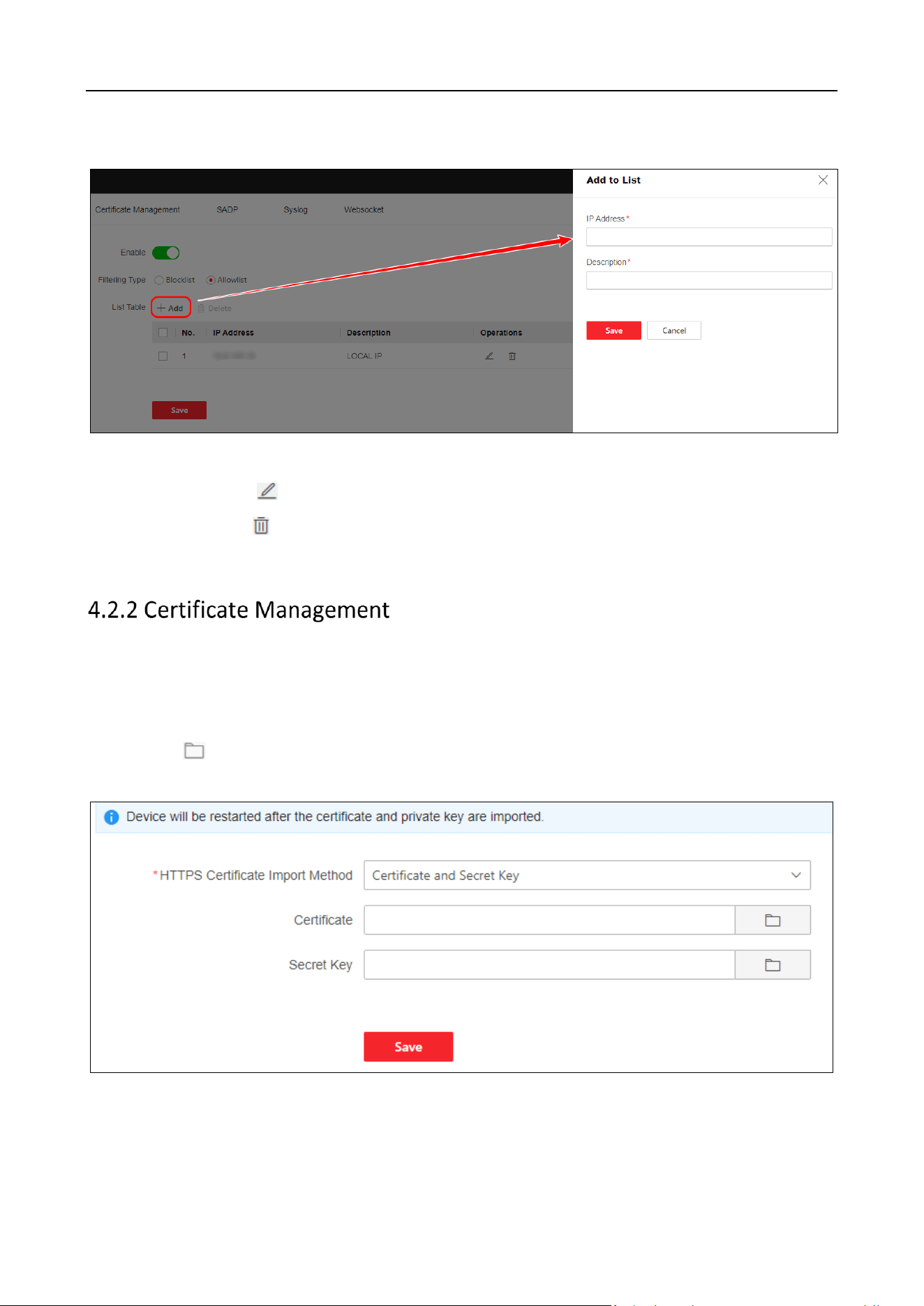
DS-6900UDI(C) Series Ultra HD Video and Audio Decoder • User Manual
38
Step 3 Click Add to add the corresponding IP address and description. Click Save.
Figure 4-7 IP Filtering Control
Modify List: Click to edit the corresponding IP address and description of the list.
Delete List: Click to delete the list.
Step 4 Click Save.
Import the HTTPS certificate and secret key.
Step 1 Click Maintenance and Security > Security Maintenance > Certificate Management.
Step 2 Set HTTPS Certificate Import Method to Certificate and Secret Key.
Step 3 Click in the Certificate or Secret Key field to select a certificate file or secret key file
from the local storage to import it.
Figure 4-8 Certificate Management
Step 4 Click Save.
DS-6900UDI(C) Series Ultra HD Video and Audio Decoder • User Manual
39
Once enabled, the device can be searched by SADP software on the same network.
Click Maintenance and Security > Security Maintenance > SADP to enable or disable SADP.
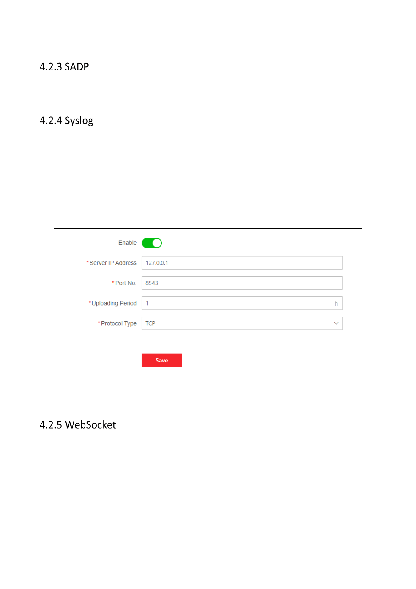
Once enabled, the device log can be uploaded to the Syslog server automatically.
Step 1 Click Maintenance and Security > Security Maintenance > Syslog to enable the function.
Server IP: IP address of the Syslog server.
Port: The port No. of the Syslog server.
Uploading Period: Set the period of uploading logs.
Protocol Type: Select TCP or UDP.
Figure 4-9 Enable Syslog
Step 2 Click Save.
Enable WebSocket to export the stream.
Click Maintenance and Security > Security Maintenance > WebSocket to enable or disable the
WebSocket.
DS-6900UDI(C) Series Ultra HD Video and Audio Decoder • User Manual
40
Chapter 5 Device Information
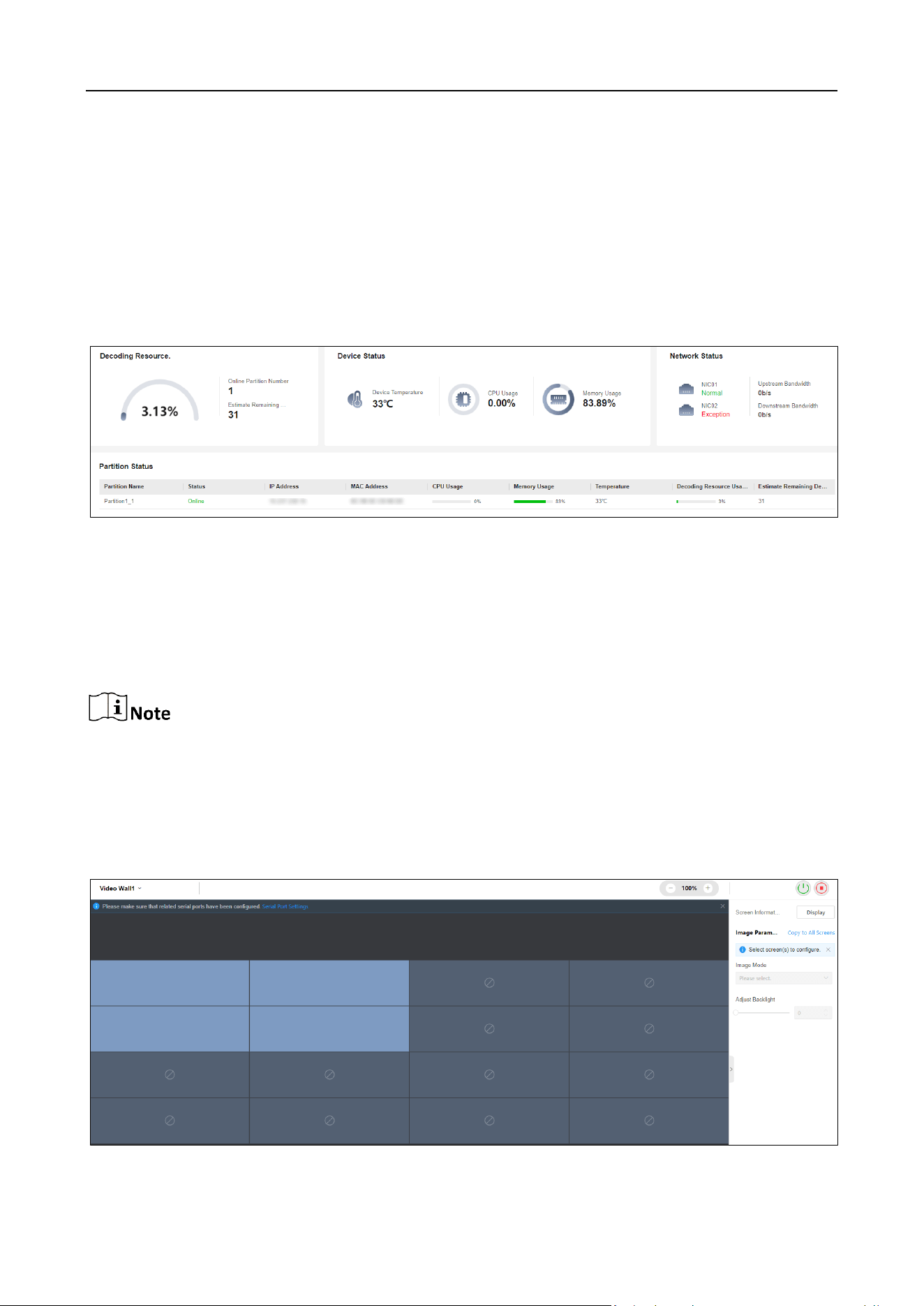
5.1 Check Device Status
You can check the device health status such as firmware usage, decoding usage, network status,
and partition status.
Click Overview to check the resource usage and device status.
Figure 5-1 Check Device Status
5.2 Screen Maintenance
You can view the screen information, configure the signal source type and image parameters, and
start up or shut down the screen.
Only partial models support screen maintenance. The actual product prevails.
Prerequisites
Make sure you have configured the related serial ports.
Step 1 Click Screen Maintenance to enter page below.
DS-6900UDI(C) Series Ultra HD Video and Audio Decoder • User Manual
41
Figure 5-2 Screen Maintenance Page
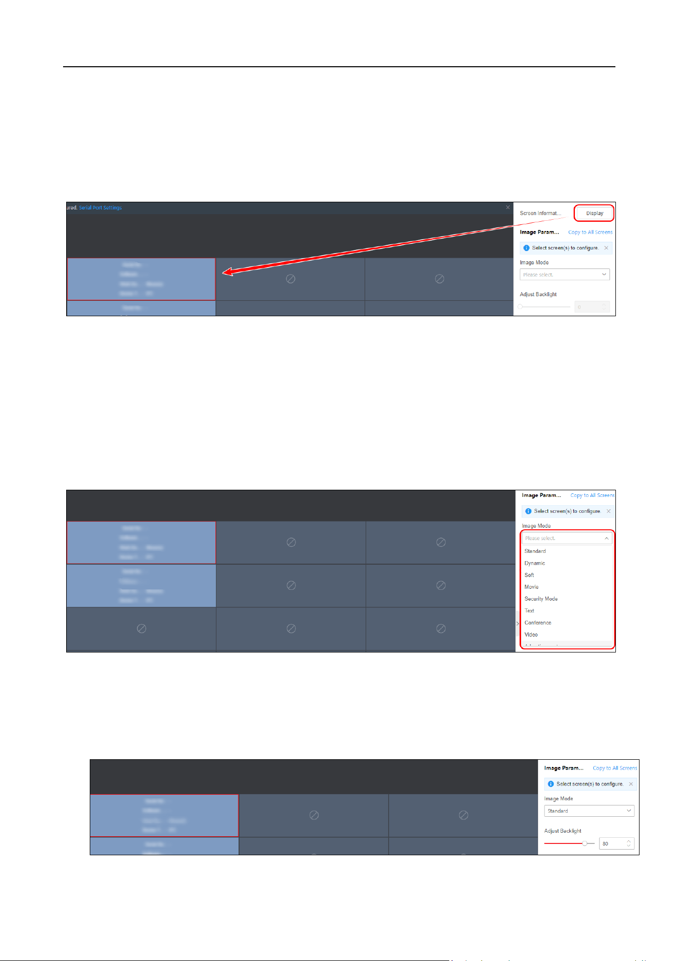
Step 2 (Optional) Perform the following operations as needed.
Display Screen Information
Click Display to show the screen information such as work duration and temperature.
Figure 5-3 Display Screen Information
Configure Signal Source Type
Select the screen to be configured, and open the corresponding drop-down list to select the
importing source type.
Modifying Image Mode
Select the screen to be configured, and open the corresponding drop-down list to select the image
mode.
Figure 5-4 Select Image Mode
Adjust Backlight
Select the screen to be configured and move the slider or enter the number to adjust screen
backlight.

DS-6900UDI(C) Series Ultra HD Video and Audio Decoder • User Manual
42
Figure 5-5 Adjust Screen Backlight
Copy to All Screens
Click Copy to All Screens to copy the current screen settings to all other screens.
Start Up/Shut Down Screen
Click / to start up/shut down the screen.
You can also start up or shut down the screen by controlling the serial port.

DS-6900UDI(C) Series Ultra HD Video and Audio Decoder • User Manual
43
Chapter 6 More Information
Scan the QR code below to acquire Smart Wall Client User Manual.

0
UD35135B