Loading ...
Loading ...
Loading ...
15
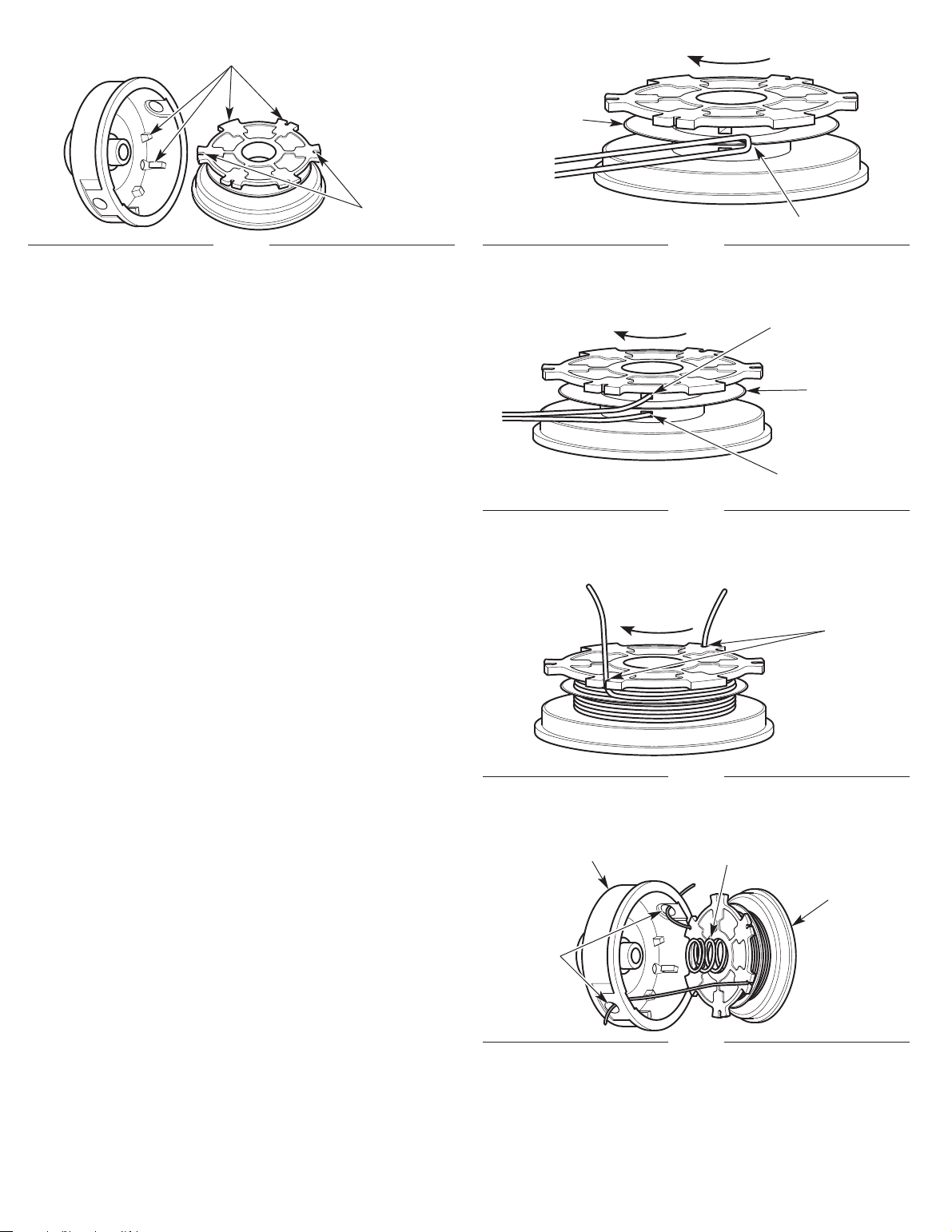
Fig. 22
Outer Spool
Inner Reel
Spring
Eyelets
Fig. 18
Indexing Teeth
Holding Slots
Part 2 - Winding New Trimming Line onto the Inner Reel
• If using single line, refer to Winding Single Line.
• If using split line, refer to Winding Split Line.
• If using a prewound inner reel, proceed to Part 3 - Installing the
Inner Reel.
Winding Single Line
1. Cut one 12-foot (3.7 m) length of new single trimming line. Fold
the line in half to create a loop in the middle.
2. Insert the loop into the slot i
n the split wall (Fig. 19). Wind the
l
ine tightly in the direction shown on the bottom of the inner reel
until about 6 inches (150 mm) of line remains. Keep the top half
of the line above the split wall and the bottom half of the line
below the split wall.
3. Insert the two 6-inch ends into the two .095 holding slots (Fig. 21).
NOTE: Failure to wind the line in the direction indicated will cause
the cutti
ng head to operate incorre
ctly.
Proceed to Part 3 - Installing the Inner Reel.
Winding Split Line
1. Cut one 6-foot (1.8 m) length of new split line trimming line. Split
each end about 6 inches (150 mm).
2. Using one split end, insert one line into the top hole and the
other line into the bottom hole in the inner reel (Fig. 20).
3. Wind the line tightly in the direction shown on the bottom of the
inner reel
. The split wall will automatically divide the line. Wind
the line until it is completely divided and about 6 inches (150 mm)
o
f line remains.
NOTE: Failure to wind the line in the direction indicated will cause
the cutting head to operate incorrectly.
4. Insert the two 6-inch ends into the two .095 holding slots (Fig. 21).
Proceed to Part 3 - Installing the Inner Reel.
Part 3 - Installing the Inner Reel
1. P
ass the two line ends through the eyelets in the outer spool
(Fig. 22).
2. Place the spring inside the inner reel (Fig. 22).
3. Insert the inner reel into the outer spool (Fig. 22). Push the inner
reel and outer spool together.
4. While holding the inner reel and outer spool together, firmly pull
the two line ends to release them from the holding slots.
5. While holding the inner reel and outer spool t
ogether,
slide the
cutting head onto the arbor (Fig. 16). Make sure that the cutting
head fits securely onto the hexagonal portion of the arbor.
6. While holding the inner reel and outer spool together, screw the
bump knob on counterclockwise (Fig. 16). Tighten the bump
knob securely.
Fig. 19
Slot
Split Wall
Fig. 20
Top Hole
Bottom Hole
Split Wall
Fig. 21
Holding
Slots
Loading ...
Loading ...
Loading ...