Introduction
This camera is designed for use as a front view or rear-facing backup
camera, and mounted on the vehicle’s front or rear bumper. When installed
with any of our camera-capable head units, the camera view can be
automatically triggered when shifting into reverse or manually triggered by
selecting the camera button from the head unit home screen.
Package Contents
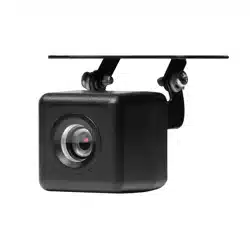
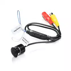
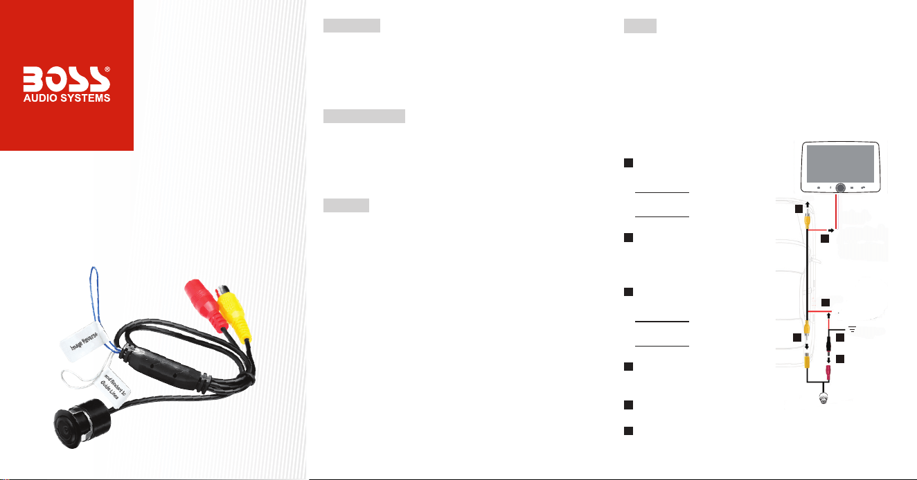
• 1x Camera with power and video sockets
• 1x Power cable with power plug
• 1x Video cable with two yellow RCA plugs
• Camera mounting kit (including one installation bit)
• User manual
Important
Please read and understand all instructions before you use your product.
Failure to follow the instructions could result in injury and/or damage that
could potentially void the warranty.
Important safety precautions
• Use of the camera must not replace other safe driving habits. Precise
control and looking around before backing up is necessary.
• Always remember that the area displayed by the camera is limited, and
certain obstacles may not be detected or not reliably detected.
Installation precautions
• WARNING: Always consult a professional installer.
• Improper wiring and mounting of the camera can cause damage, injury
or accident. Have installation performed by a professional only. Contact
our technical support for any installation questions.
• Disconnect the negative terminal of the vehicle battery prior to wiring.
• Hide wires under car oor mat or through car headliner. Make sure wires
are not squeezed or damaged by sharp edges. Use rubber grommets if
passing through sheet metal.
Wiring
• Follow two steps described below to install this product as a front camera
or a rear camera.
• The rear camera view automatically turns on when reversing. Ensure
you connect the “Reverse Input” wire on your head unit to the vehicle’s
reverse light for reverse trigger. Front camera view is not accessible
when reversing.
• Both rear and front camera view can be selected via Home screen
options on your head unit.
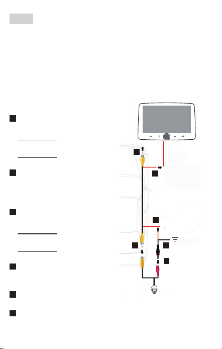
1. Connect the video cables.
a
Connect one yellow RCA plug of
the video cable to your head unit.
Front camera: to “Front Camera
Input” RCA socket.
Rear camera: to “Rear Camera
Input” RCA socket.
b
Connect the other yellow RCA plug
of the video cable to the yellow
RCA socket on the camera.
2. Connect the power cables.
c
Connect the red split wire of the
video cable to your head unit.
Front camera: to “Front Camera
Power Output” wire.
Rear camera: to “Rear Camera
Power Output” wire.
d
Connect the other red split wire of
the video cable to the red wire of
the power cable.
e
Connect the black (ground) wire of
the power cable to the car chassis.
f
Connect the black plug of the power cable to the red socket on the
camera.
2
(+)
(-)
a
b
c
d
e
f
Front or rear cam
power wire
Camera
1 2
0723

Introduction
This camera is designed for use as a front view or rear-facing backup
camera, and mounted on the vehicle’s front or rear bumper. When installed
with any of our camera-capable head units, the camera view can be
automatically triggered when shifting into reverse or manually triggered by
selecting the camera button from the head unit home screen.
Package Contents
• 1x Camera with power and video sockets
• 1x Power cable with power plug
• 1x Video cable with two yellow RCA plugs
• Camera mounting kit (including one installation bit)
• User manual
Important
Please read and understand all instructions before you use your product.
Failure to follow the instructions could result in injury and/or damage that
could potentially void the warranty.
Important safety precautions
• Use of the camera must not replace other safe driving habits. Precise
control and looking around before backing up is necessary.
• Always remember that the area displayed by the camera is limited, and
certain obstacles may not be detected or not reliably detected.
Installation precautions
• WARNING: Always consult a professional installer.
• Improper wiring and mounting of the camera can cause damage, injury
or accident. Have installation performed by a professional only. Contact
our technical support for any installation questions.
• Disconnect the negative terminal of the vehicle battery prior to wiring.
• Hide wires under car oor mat or through car headliner. Make sure wires
are not squeezed or damaged by sharp edges. Use rubber grommets if
passing through sheet metal.
Wiring
• Follow two steps described below to install this product as a front camera
or a rear camera.
• The rear camera view automatically turns on when reversing. Ensure
you connect the “Reverse Input” wire on your head unit to the vehicle’s
reverse light for reverse trigger. Front camera view is not accessible
when reversing.
• Both rear and front camera view can be selected via Home screen
options on your head unit.
1. Connect the video cables.
a
Connect one yellow RCA plug of
the video cable to your head unit.
Front camera: to “Front Camera
Input” RCA socket.
Rear camera: to “Rear Camera
Input” RCA socket.
b
Connect the other yellow RCA plug
of the video cable to the yellow
RCA socket on the camera.
2. Connect the power cables.
c
Connect the red split wire of the
video cable to your head unit.
Front camera: to “Front Camera
Power Output” wire.
Rear camera: to “Rear Camera
Power Output” wire.
d
Connect the other red split wire of
the video cable to the red wire of
the power cable.
e
Connect the black (ground) wire of
the power cable to the car chassis.
f
Connect the black plug of the power cable to the red socket on the
camera.
2
(+)
(-)
a
b
c
d
e
f
Front or rear cam
power wire
Camera
1 2
0723
Troubleshooting
Problem Solution
No image Ensure the camera’s power cable is securely plugged.
Ensure there is correct and secure wiring between the
camera and your head unit.
Ensure the reverse input wire on your head unit is
connected to the vehicle’s reverse light.
Ensure correct camera settings on your head unit.
Image blurry Check for water drops or dust on the camera lens.
Clean it with a damp, ber-free cloth.
Image shaking Ensure the camera is tightly mounted.
Image slanted Adjust the camera mounting bracket.
Image Setting
• To remove the on-screen parking guidelines, cut the white wire loop
which splits from the camera’s cable.
• If the camera image appears reverse, cut the blue wire loop which splits
from the camera’s cable.
• Make sure to unplug the power cable from the camera and plug it again
to enable the new setting (after cutting the white or blue wire loop).
Specications
Power supply ................................... 12 VDC
Viewing angle ..................................170°
TV system ........................................NTSC
Video output ....................................1.0 vp-p, 75 Ω
S/N ratio ...........................................≤45 dB
Ingress protection rating .................. IP67 (waterproof)
Operating conditions ........................ -22 to +140°F (-30 to +60°C)
max. 95% RH
White balance ..................................Auto
Illumination ......................................min. 0.1 lux
Automatic gain control (AGC) ..........Auto
Resolution (TV lines) .......................480
Electronic shutter speed .................. 1/60 (NTSC)
Effective pixels .................................648 x 488
Flush mount hole ............................. 0.73” (18.5 mm)
Cable length .................................... 197”/5m (video cable); 39”/1m (power
cable); 20”/0.5m (camera’s cable)
Specications are subject to change without notice.
43 5
0723
Mounting
Important notes on mounting
• When making modications to the vehicle due to the installation, make
sure trafc safety and stability of the vehicle is not impaired.
• When drilling or cutting any holes on your vehicle, make sure the fuel
tank, fuel lines, hydraulic lines and electrical wiring are not damaged.
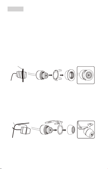
Option 1: Flush mount
1. Select a suitable location on the front or rear of your vehicle (e.g. front
or rear bumper). Then use the supplied installation bit (0.73”/18.5mm) to
drill a hole which is used to secure the camera.
2. Flush mount the camera as illustrated below. No screws are required.
Vehicle body
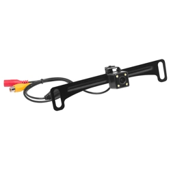
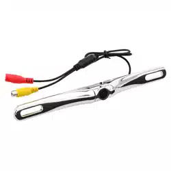
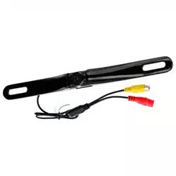
Option 2: Hanging mount
1. Select a suitable location on the front or rear of your vehicle (e.g. front or
rear bumper). Then cut an appropriate hole for the camera cable, and drill
two screw holes for the mounting bracket.
2. Use the supplied two screws to x the supplied bracket then attach the
camera to the bracket as illustrated below.
Vehicle body

Troubleshooting
Problem Solution
No image Ensure the camera’s power cable is securely plugged.
Ensure there is correct and secure wiring between the
camera and your head unit.
Ensure the reverse input wire on your head unit is
connected to the vehicle’s reverse light.
Ensure correct camera settings on your head unit.
Image blurry Check for water drops or dust on the camera lens.
Clean it with a damp, ber-free cloth.
Image shaking Ensure the camera is tightly mounted.
Image slanted Adjust the camera mounting bracket.
Image Setting
• To remove the on-screen parking guidelines, cut the white wire loop
which splits from the camera’s cable.
• If the camera image appears reverse, cut the blue wire loop which splits
from the camera’s cable.
• Make sure to unplug the power cable from the camera and plug it again
to enable the new setting (after cutting the white or blue wire loop).
Specications
Power supply ................................... 12 VDC
Viewing angle ..................................170°
TV system ........................................NTSC
Video output ....................................1.0 vp-p, 75 Ω
S/N ratio ...........................................≤45 dB
Ingress protection rating .................. IP67 (waterproof)
Operating conditions ........................ -22 to +140°F (-30 to +60°C)
max. 95% RH
White balance ..................................Auto
Illumination ......................................min. 0.1 lux
Automatic gain control (AGC) ..........Auto
Resolution (TV lines) .......................480
Electronic shutter speed .................. 1/60 (NTSC)
Effective pixels .................................648 x 488
Flush mount hole ............................. 0.73” (18.5 mm)
Cable length .................................... 197”/5m (video cable); 39”/1m (power
cable); 20”/0.5m (camera’s cable)
Specications are subject to change without notice.
43 5
0723
Mounting
Important notes on mounting
• When making modications to the vehicle due to the installation, make
sure trafc safety and stability of the vehicle is not impaired.
• When drilling or cutting any holes on your vehicle, make sure the fuel
tank, fuel lines, hydraulic lines and electrical wiring are not damaged.
Option 1: Flush mount
1. Select a suitable location on the front or rear of your vehicle (e.g. front
or rear bumper). Then use the supplied installation bit (0.73”/18.5mm) to
drill a hole which is used to secure the camera.
2. Flush mount the camera as illustrated below. No screws are required.
Vehicle body
Option 2: Hanging mount
1. Select a suitable location on the front or rear of your vehicle (e.g. front or
rear bumper). Then cut an appropriate hole for the camera cable, and drill
two screw holes for the mounting bracket.
2. Use the supplied two screws to x the supplied bracket then attach the
camera to the bracket as illustrated below.
Vehicle body