

Copyright
©
2021
Hanwha Techwin
Co., Ltd. All rights reserved.
Trademark
Each of trademarks herein is registered. The name of this product and other trademarks mentioned in this manual are the registered trademark of their
respective company.
Restriction
Copyright of this document is reserved. Under no circumstances, this document shall be reproduced, distributed or changed, partially or wholly, without
formal authorization.
Disclaimer
Hanwha Techwin
makes the best to verify the integrity and correctness of the contents in this document, but no formal guarantee shall be
provided. Use of this document and the subsequent results shall be entirely on the user’s own responsibility.
Hanwha Techwin
reserves the
right to change the contents of this document without prior notice.
※
Design and specications are subject to change without prior notice.
※
The initial administrator ID is “admin” and the password should be set when logging in for the rst time.
Please change your password every three months to safely protect personal information and to prevent the damage of the information
theft.
Please, take note that it’s a user’s responsibility for the security and any other problems caused by mismanaging a password.
Network Camera
User Manual
English _3
! OVERVIEW
IMPORTANT SAFETY INSTRUCTIONS
1. Read these instructions.
2. Keep these instructions.
3. Heed all warnings.
4. Follow all instructions.
5. Do not use this apparatus near water.
6. Clean the contaminated area on the product surface with a soft, dry cloth or a damp cloth.
(Do not use a detergent or cosmetic products that contain alcohol, solvents or surfactants or oil constituents
as they may deform or cause damage to the product.)
7. Do not block any ventilation openings, Install in accordance with the manufacturer’s instructions.
8. Do not install near any heat sources such as radiators, heat registers, stoves, or other apparatus (including
amplifiers) that produce heat.
9. Do not defeat the safety purpose of the polarized or grounding-type plug. A polarized plug has two blades
with one wider than the other. A grounding type plug has two blades and a third grounding prong. The wide
blade or the third prong are provided for your safety. If the provided plug does not fit into your outlet, consult
an electrician for replacement of the obsolete outlet.
10. Protect the power cord from being walked on or pinched particularly at plugs, convenience receptacles, and
the point where they exit from the apparatus.
11. Only use attachments/ accessories specified by the manufacturer.
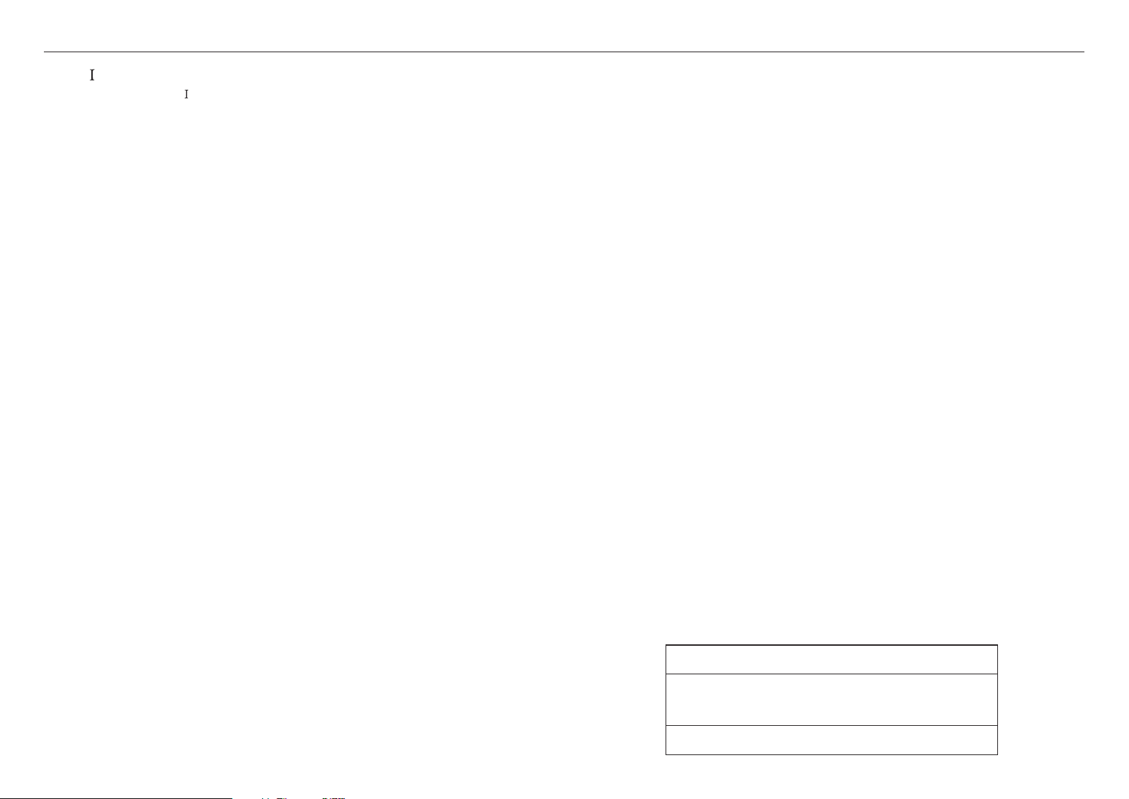
12. Use only with the cart, stand, tripod, bracket, or table specified by the manufacturer,
or sold with the apparatus. When a cart is used, use caution when moving the cart/
apparatus combination to avoid injury from tip-over.
13. Unplug this apparatus during lighting storms or when unused for long periods of time.
14. Refer all servicing to qualified service personnel. Servicing is required when the apparatus
has been damaged in any way, such as power-supply cord or plug is damaged, liquid has
been spilled or objects have fallen into the apparatus, the apparatus has been exposed to rain or moisture,
does not operate normally, or has been dropped.
15. This product is intended to be supplied by a Listed Power Supply Unit marked “Class 2” or “LPS” and rated
from
12 Vdc, 1.67 A or PoE, 0.43 A. (XND-6083RV/XND-8083RV/XND-8093RV/XND-9083RV/XNV-6083R/
XNV-8083R/XNV-8093R/XNV-9083R/XNO-6083R/XNO-8083R/XNO-9083R)
16. This product is intended to be supplied by a Listed Power Supply Unit marked “Class 2” or “LPS” and rated
from
12 Vdc 1.08 A, or PoE, 0.27 A. (XNB-6003/XNB-8003/XNB-9003)
17. This product is intended to be supplied by isolation power.
18. If you use excessive force when installing the product, the camera may be damaged and malfunction.
If you forcibly install the product using non-compliant tools, the product may be damaged.
19. Do not install the product in a place where chemical substances or oil mist exists or may be generated. As
edible oils such as soybean oil may damage or warp the product, do not install the product in the kitchen or
near the kitchen table.
This may cause damage to the product.
20. When installing the product, be careful not to allow the surface of the product to be stained with chemical
substance.
Some chemical solvents such as cleaner or adhesives may cause serious damage to the product’s surface.
21. If you install/disassemble the product in a manner that has not been recommended, the production functions/
performance may not be guaranteed.
Install the product by referring to “Installation & connection” in the user manual.
22. Installing or using the product in water can cause serious damage to the product.
23. Although a rapid change in temperature could cause frost inside the dome, there will be no problem with the
video.
24. This device has been verified using STP cable. The use of appropriate GND grounding and STP cable
is recommended to effectively protect your product and property from transient voltage, thunderstroke,
communication interruption.
WARNING
TO REDUCE THE RISK OF FIRE OR ELECTRIC SHOCK, DO NOT EXPOSE THIS PRODUCT
TO RAIN OR MOISTURE. DO NOT INSERT ANY METALLIC OBJECT THROUGH THE
VENTILATION GRILLS OR OTHER OPENNINGS ON THE EQUIPMENT.
Apparatus shall not be exposed to dripping or splashing and that no objects filled with liquids,
such as vases, shall be placed on the apparatus.
To prevent injury, this apparatus must be securely attached to the Wall/ceiling in accordance
with the installation instructions.
CAUTION
CAUTION
RISK OF ELECTRIC SHOCK.
DO NOT OPEN
CAUTION
: TO REDUCE THE RISK OF ELECTRIC SHOCK.
DO NOT REMOVE COVER (OR BACK).
NO USER SERVICEABLE PARTS INSIDE.
REFER SERVICING TO QUALIFIED SERVICE PERSONNEL.
EXPLANATION OF GRAPHICAL SYMBOLS
The lightning flash with arrowhead symbol, within an equilateral triangle, is
intended to alert the user to the presence of “dangerous voltage” within the
product’s enclosure that may be of sufficient magnitude to constitute a risk of
electric shock to persons.
The exclamation point within an equilateral triangle is intended to alert the user to
the presence of important operating and maintenance (servicing) instructions in
the literature accompanying the product.
overview
overview
4_ overview
Class construction
An apparatus with CLASS
construction shall be connected to a MAINS socket outlet with a
protective earthing connection.
Battery
Batteries(battery pack or batteries installed) shall not be exposed to excessive heat such as
sunshine, fire or the like.
The battery cannot be replaced.
Disconnection Device
Disconnect the main plug from the apparatus, if it’s defected. And please call a repair man in
your location.
When used outside of the U.S., it may be used HAR code with fittings of an approved
agency is employed.
CAUTION
RISK OF EXPLOSION IF BATTERY IS REPLACED BY AN INCORRECT TYPE.
DISPOSE OF USED BATTERIES ACCORDING TO THE INSTRUCTIONS.
ATTENTION
IL Y A RISQUE D’EXPLOSION SI LA BATTERIE EST REMPLACÉE PAR UNE BATTERIE DE
TYPE INCORRECT.
METTRE AU REBUT LES BATTERIES USAGÉES CONFORMÉMENT AUX INSTRUCTIONS.
CAUTION
These servicing instructions are for use by qualified service personnel only.
To reduce the risk of electric shock do not perform any servicing other than that contained in
the operating instructions unless you are qualified to do so.
Please use the input power with just one camera and other devices must not be connected.
When a new product box is opened (or during the initial use of the product), moisture might
build up on the glass of the camera. The built-up moisture disappears naturally within a few
hours after powered on.
Do not arbitrarily loosen or tighten the gore valve.
The ITE is to be connected only to PoE networks without routing to the outside plant.
The wired LAN hub providing power over the Ethernet (PoE) in accordance with IEEE 802.3af
shall be a UL Listed device with the output evaluated as a Limited Power Source as defined in
UL60950-1 or PS2 as defined in UL62368-1. (XNB-6003/XNB-8003/XNB-9003)
The wired LAN hub providing power over the Ethernet (PoE) in accordance with IEEE 802.3at
shall be a UL Listed device with the output evaluated as a Limited Power Source as defined in
UL60950-1 or PS2 as defined in UL62368-1. (XNV-6083R/XNV-8083R/XNV-8093R/XNV-9083R/
XND-6083RV/XND-8083RV/XND-8093RV/XND-9083RV/XNO-6083R/XNO-8083R/XNO-9083R)
Unit is intended for installation in a Network Environment 0 as defined in IEC TR 62102.
As such, associated Ethernet wiring shall be limited to inside the building.
Please read the following recommended safety precautions carefully.
~
Do not place this apparatus on an uneven surface.
~
Do not install on a surface where it is exposed to direct sunlight, near heating equipment or
heavy cold area.
~
Do not place this apparatus near conductive material.
~
Do not attempt to service this apparatus yourself.
~
Do not place a glass of water on the product.
~
Do not install near any magnetic sources.
~
Do not block any ventilation openings.
~
Do not place heavy items on the product.
~
Please wear protective gloves when installing/removing the camera.
The high temperature of the product surface may cause a burn.
User’s Manual is a guidance book for how to use the products.
The meaning of the symbols are shown below.
~
Reference : In case of providing information for helping of product’s usages
~
Notice : If there’s any possibility to occur any damages for the goods and human caused by
not following the instruction
※ Please read this manual for the safety before using of goods and keep it in the safe place.
We do not guarantee the quality of third-party products (e.g. lenses, accessories) that you
separately purchase.
In particular installation environments, there might be interference in radio communications.
When interference of electromagnetic waves occurs between the product and radio
communication device, it is recommended to keep a certain distance between the two or
change the direction of the receiving antenna.
WARNING
To Prevent damage which may caused by IR LED, don't stare at operating lamp.
For below models only.
XNV-6083R/XNV-8083R/XNV-9083R
XND-6083RV/XND-8083RV/XND-9083RV
XNO-6083R/XNO-8083R/XNO-9083R
Risk Group 1
WARNING IR emitted from this product.
Do not stare at operating lamp.
Product tested against IEC 62471

English _5
! OVERVIEW
CONTENTS
OVERVIEW
3
3 Important Safety Instructions
6 Recommended PC Specifications
6 Recommended Micro SD/SDHC/SDXC
Memory Card Specifications
6 NAS recommended specs
6 Video output
8 Optional Accessories for Installation
VANDAL DOME CAMERA
9
9 What’s Included
9 At a Glance
10 Installation
INDOOR DOME CAMERA
17
17 What’s Included
17 At a Glance
18 Installation
BOX CAMERA
31
31 What’s Included
31 At a Glance
32 Mounting the Lens
33 Inserting/Removing a Micro SD card
INSTALLATION & CONNECTION
34
34 Adjusting the monitoring direction for the
camera
35 Connecting with other Device
NETWORK CONNECTION AND
SETUP
40
40 Connecting the Camera Directly to Local
Area Networking
40 Connecting the Camera Directly to a DHCP
Based DSL/Cable Modem
41 Using Device Manager
41 Automatically searching camera
41 Configuring IP address
42 Manually registering camera
42 Automatically configuring IP
43 Port Range Forward (Port Mapping) Setup
44 Connecting to the Camera from a Shared
Local PC
44 Connecting to the Camera from a Remote
PC via the Internet
BULLET CAMERA
24
24 What’s Included
24 At a Glance
25 Installation
WEB VIEWER
45
45 Connecting to the Camera
46 Password setting
46 Login
46 Camera Web Viewer Setup
APPENDIX
47
47 Troubleshooting

overview
6_ overview
RECOMMENDED PC SPECIFICATIONS
~
CPU : Intel(R) Core(TM) i7 3.4 GHz or higher
~
RAM : 8G or higher
~
Recommended browser: Chrome
~
Supported browsers: Chrome, Safari, Firefox, MS Edge(chromium based)
~
Supported OS : Windows, Mac, Linux, Android, iOS, Chrome
~
Verification environment
- Windows 10: Google Chrome version 80 or later, Firefox version 72 or later, MS Edge version 83 or later
- Mac 10.13/14: Safari version 11.0.1 or later
※
The video play performance of the web viewer depends on the performance of the user’s CPU and GPU.
RECOMMENDED MICRO SD/SDHC/SDXC MEMORY CARD
SPECIFICATIONS
~
Recommended capacity : 16GB to
512GB (MLC type required)
~
Recommended Manufacturers : SanDisk, Transcend
~
Product Type : High endurance
~
The compatibility varies depending on the card manufacturers and types.
NAS RECOMMENDED SPECS
~
Recommended capacity : 200GB or higher is recommended.
~
For this camera, you are recommended to use a NAS with the following manufacturer’s specs.
Recommended products : QNAP NAS, Synology NAS
VIDEO OUTPUT
~
The CVBS type of video output is initially set to NTSC. This may vary for different regions, so refer to the
following directory to change the settings if necessary.
Camera web viewer's <Setup ( )>
;
<Video & Audio>
;
<Video setup>
;
<Video output>
;
<CVBS type> On the menu, select NTSC or PAL.
English _7
! OVERVIEW
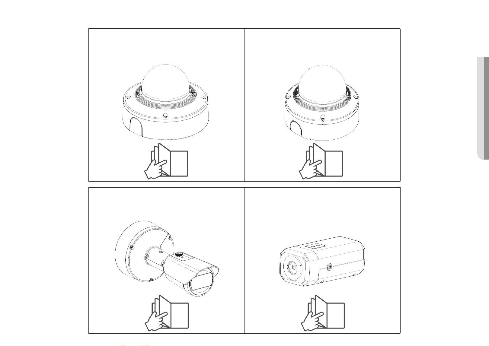
Vandal Dome Camera
XNV-6083R/XNV-8083R/XNV-8093R/XNV-9083R
Indoor Dome Camera
XND-6083RV/XND-8083RV/XND-8093RV/XND-9083RV
9 17
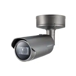
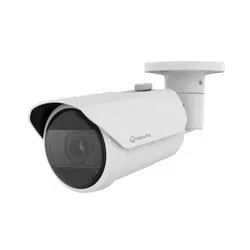
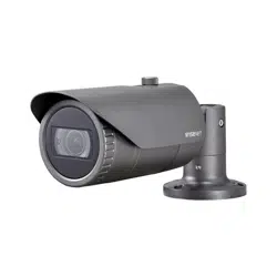
Bullet Camera
XNO-6083R/XNO-8083R/XNO-9083R
Box Camera
XNB-6003/XNB-8003/XNB-9003
24 31
overview
8_ overview
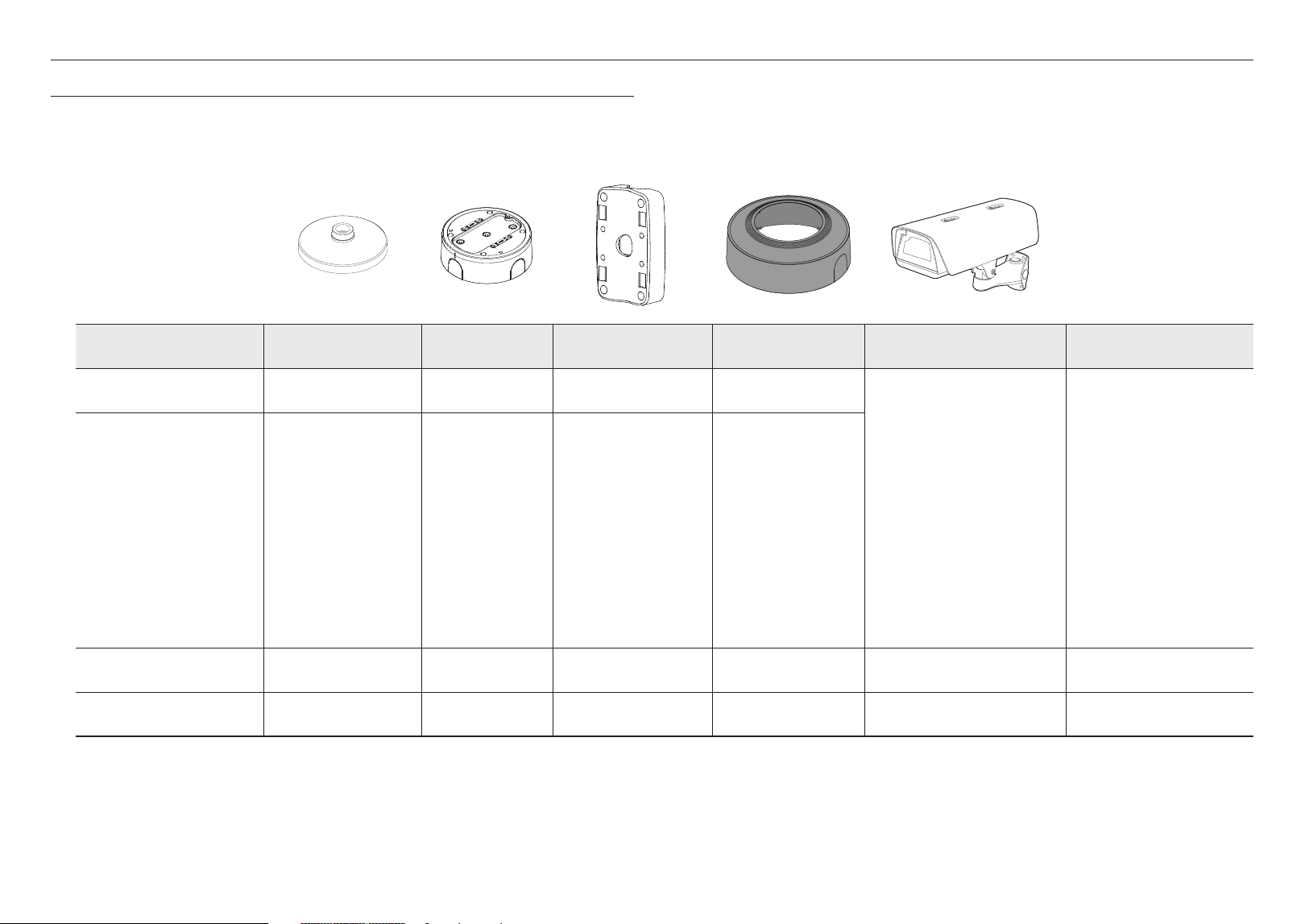
Model name Hanging Mount Backbox Pole Mount Skin Cover Housing All
XNV-6083R/XNV-8083R/
XNV-8093R/XNV-9083R
SBP-187HMW SBV-180WW SBC-180B (Black)
SBP-300LMW (Parapet Mount)
SBP-156LMW (Parapet Mount)
SBP-300CMW (Ceiling Mount)
SBP-156CMW (Ceiling Mount)
SBP-300WMW (Wall Mount)
SBP-300WMW1 (Wall Mount)
SBP-300NBW (Instalation Box)
SBP-300NBW (Wall Mount Base)
SBP-300PMW (Pole Mount)
SBP-300PMW1 (Pole Mount)
SBP-300KMW (Corner Mount)
SBP-300KMW1 (Corner Mount)
XND-6083RV/XND-8083RV/
XND-8093RV/XND-9083RV
SBP-167HMW SBC-160B (Black)
XNO-6083R/XNO-8083R/
XNO-9083R
SBP-300PMW1 SBP-300KMW1 (Corner Mount)
XNB-6003/XNB-8003/
XNB-9003
SHB-4301HP
OPTIONAL ACCESSORIES FOR INSTALLATION
You can purchase appropriate optional accessories available.
English _9
! VANDAL DOME CAMERA
vandal dome camera
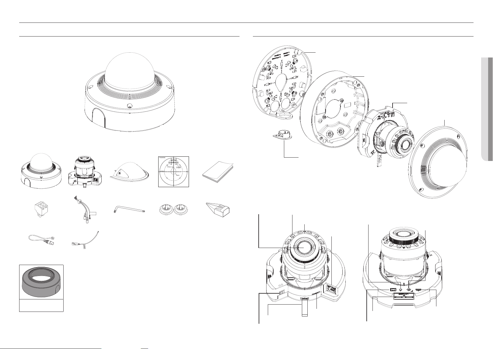
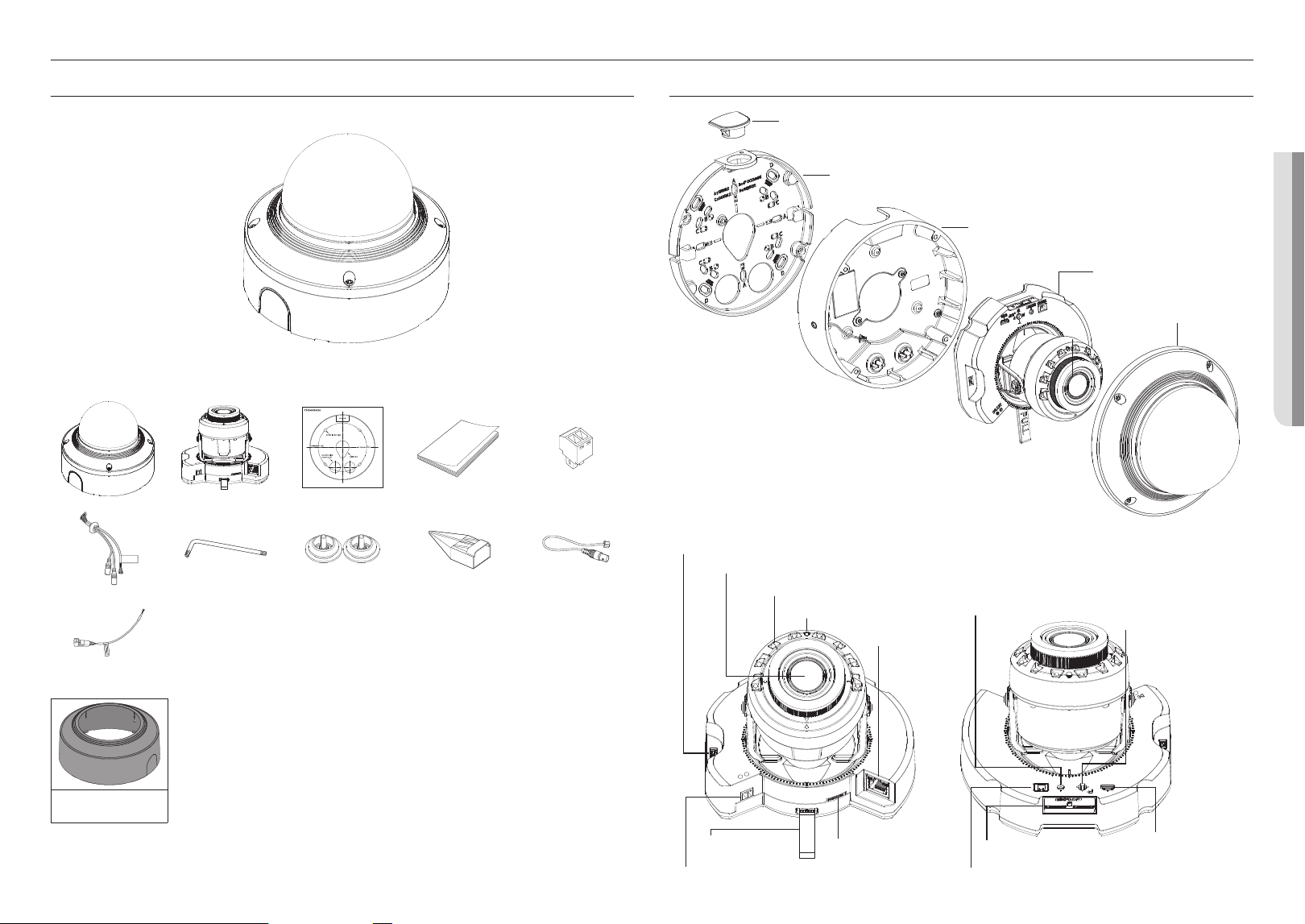
WHAT’S INCLUDED
As for each sales country, accessories are not the same.
<XNV-6083R/XNV-8083R/XNV-8093R/XNV-9083R>
DC 12V
+
-
ALARM AUDIO
PoE+
PULL
Options (not included)
SBC-180B
(Color : Black)
M
`
Use installation screws of at least M4, L30 for the installation of this product.
AT A GLANCE
Mount-plate
a
Camera-case
b
Camera-module
c
Dome-cover
d
Pipe-cover
e
DC 12V
+
-
ALARM AUDIO
PULL
PoE+
g
IR LED
h
Illumination Sensor
l
Power port (DC 12 V)
n
Audio/Alarm
cable port
i
Network
Port
PoE+
VIDEO RESET W
T
N F
AF
USB
1 2
+
j
Reset button
k
Zoom/Focus
Control Button
q
Micro USB
port
p
Micro SD card slot
o
Test monitor out port
m
Separator strap
f
Lens
10_ vandal dome camera
vandal dome camera
INSTALLATION
J
`
This camera is waterproof and in compliance with the IP67 / IP6K9K spec, but the jack connected to the external cable is not.
You are recommended to install this product below the edge of eaves to prevent the cable from being externally exposed.
Precautions before installation
Ensure you read out the following instructions before installing the camera:
~
Select an installation site that can hold at least 5 times the camera’s weight.
~
Stuck-in or peeled-off cables can cause damage to the product or a fire.
~
For safety purposes, keep anyone else away from the installation site.
And put aside personal belongings from the site, just in case.
~
If the product is installed with excessive force, it may cause damage to the camera due to malfunction.
Forcing assembly using non-compliant tools may damage the product.
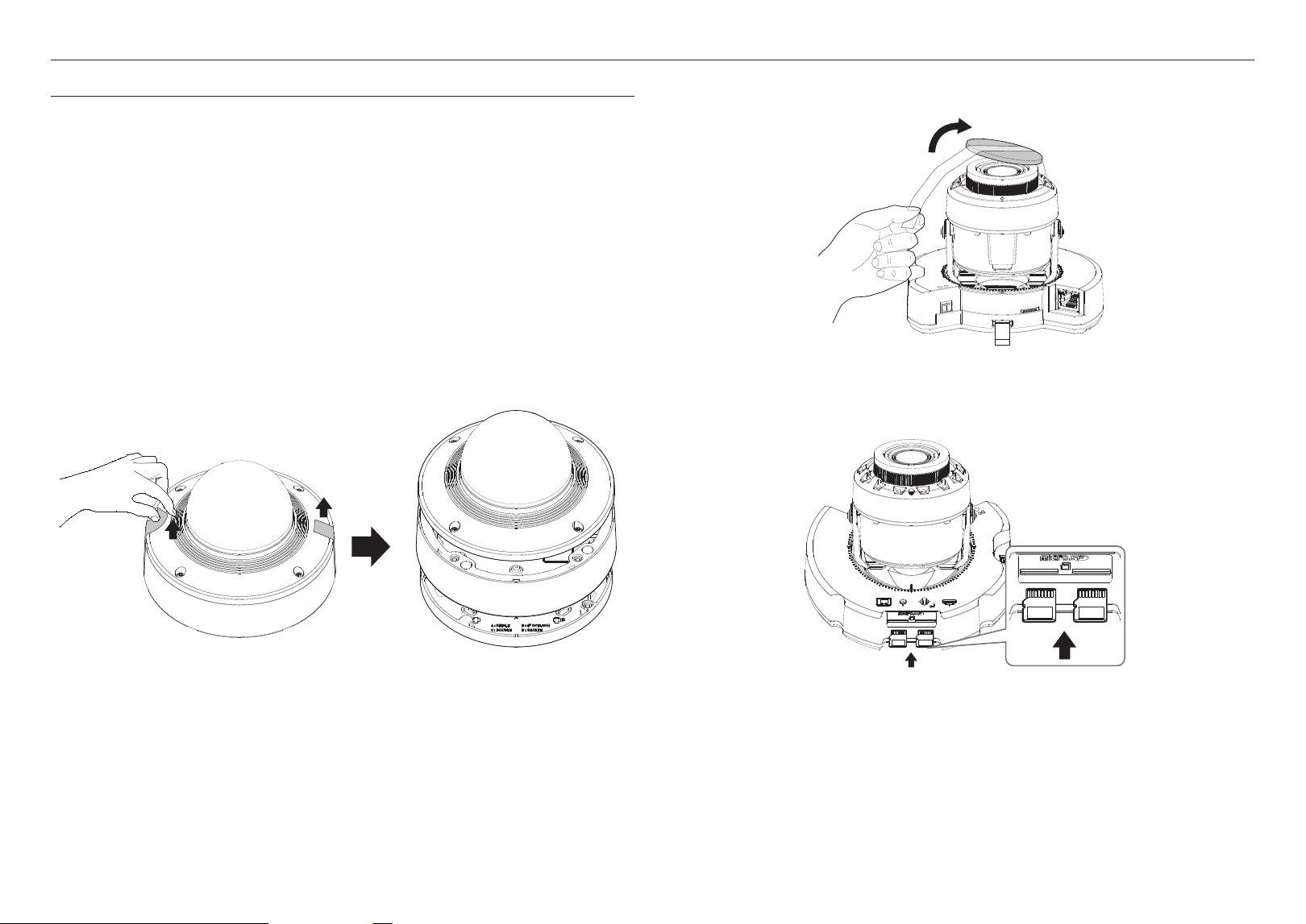
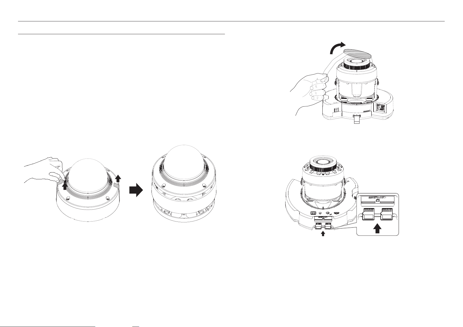
Removal
1. Peel off the fix tape and remove the dome cover, camera case, and mount plate.
2. Take off the lens cover protecting the camera lens.
DC 12V
+
-
ALARM AUDIO
PoE+
PULL
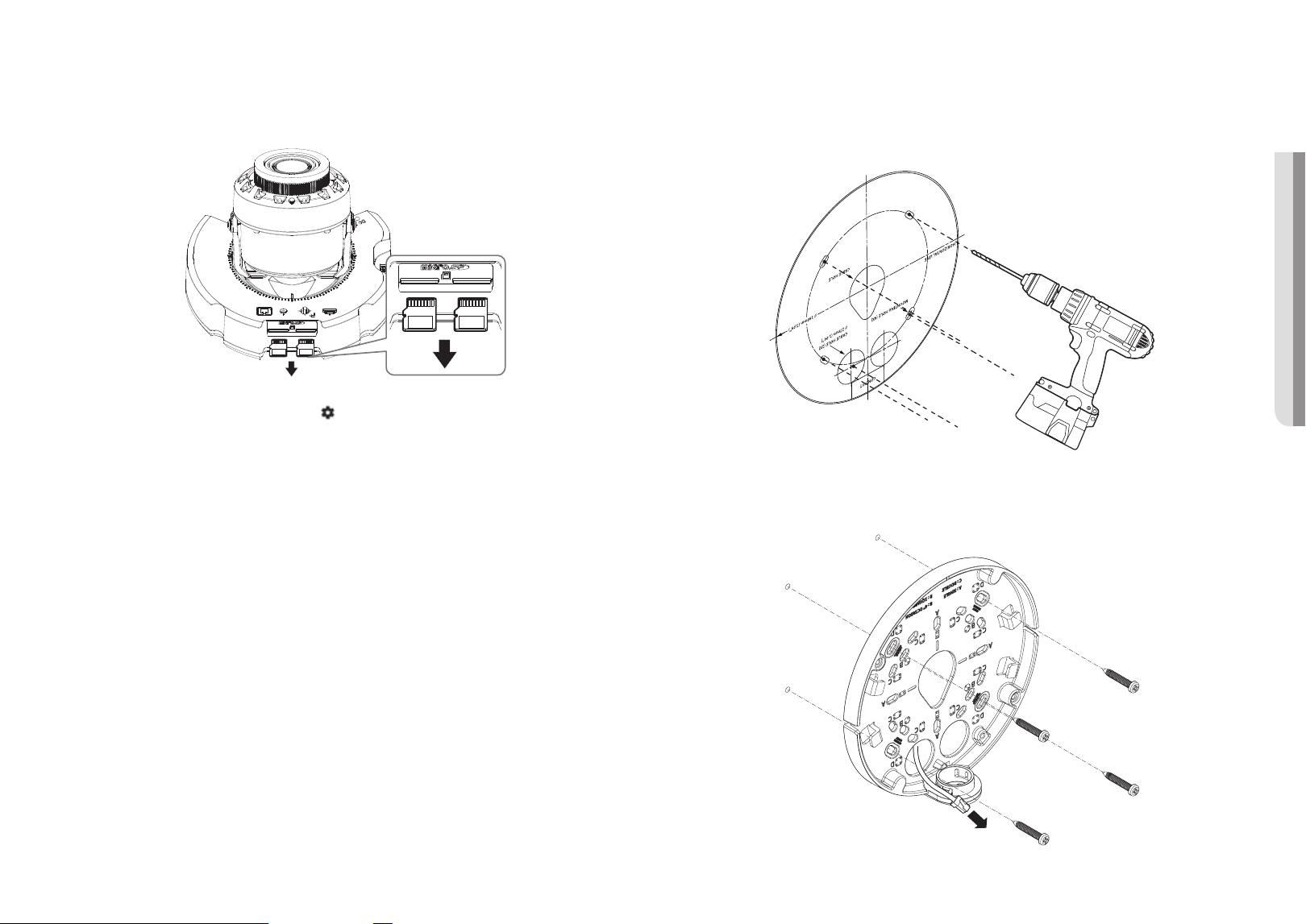
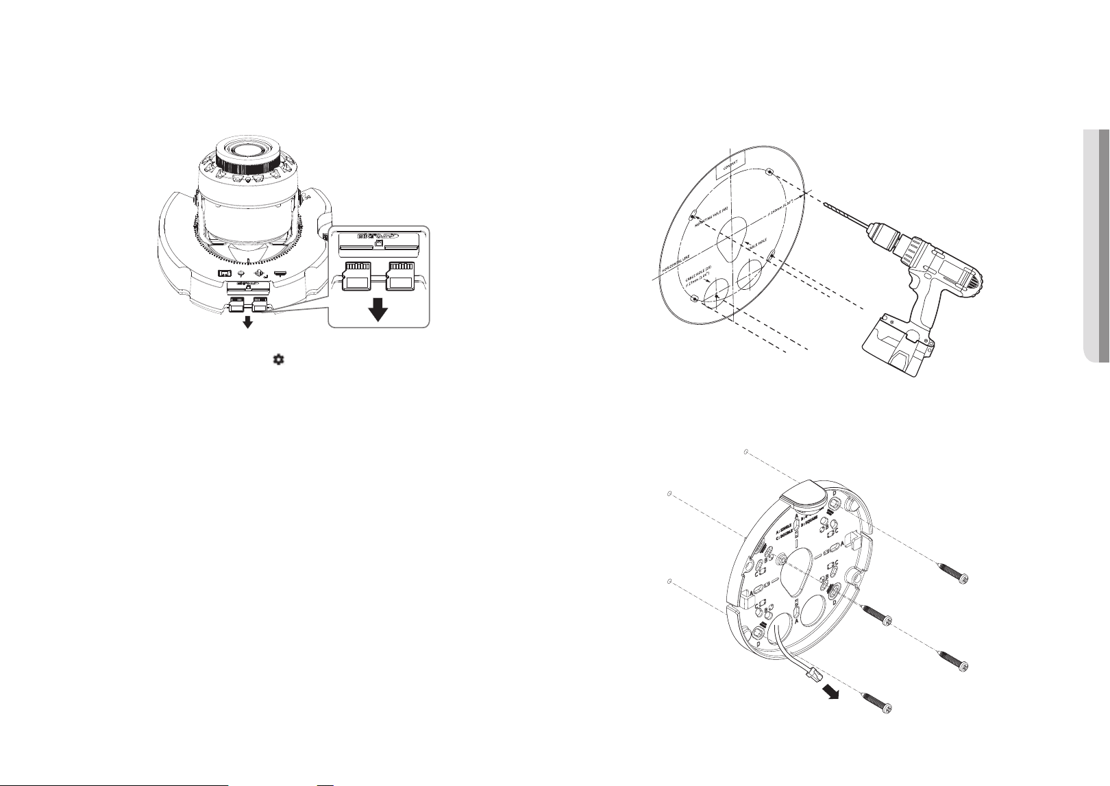
Inserting a Micro SD card
Slide the Micro SD card into the Micro SD card slot on the camera module in the direction of the arrow.
PoE+
VIDEO RESET W
T
N F
AF
USB
1 2
+
VIDEO RESET W
1 2
J
`
Before installing the camera, the Micro SD card should be inserted while the power source and the body are separated.
`
Do not forcefully insert it in the reverse direction. It might damage your Micro SD card and your product.
`
When it rains or the humidity is high, insertion or ejection of a Micro SD card is not recommended.
`
When installing/removing the Micro SD card, make sure you put the product body on a flat ground before working on it in order
to prevent accidents due to loss or drop of any parts.
English _11
! VANDAL DOME CAMERA
Removing a Micro SD card
Gently press down on the exposed end of the Micro SD card as shown in the diagram to eject the Micro SD
card from the slot.
PoE+
VIDEO RESET W
T
N F
AF
USB
1 2
+
VIDEO RESET W
1 2
J
`
Before removing the Micro SD card, in <Setup ( )>-<Event>-<Storage>, set the device to <Off> and press the [Apply]
button and turn the camera off.
`
If you turn off the camera or remove the Micro SD card that contains data from the product, the data may be lost or damaged.
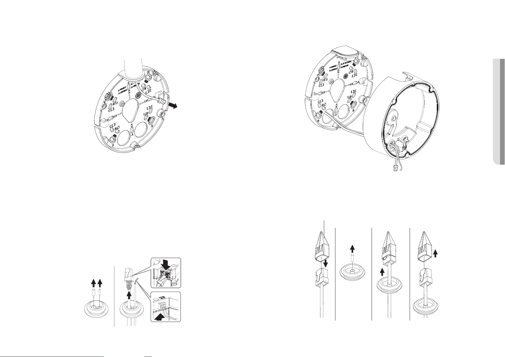
Installation (mount plate)
[Directly installing on wall/ceiling]
1-1. Attach the installation template on the desired surface and drill holes for screws and cables.
1-2. Fix the mount plate using appropriate screws.
1-3. Pull out necessary cables among network/power/audio/alarm cables through the hole in the mount
plate.
12_ vandal dome camera
vandal dome camera
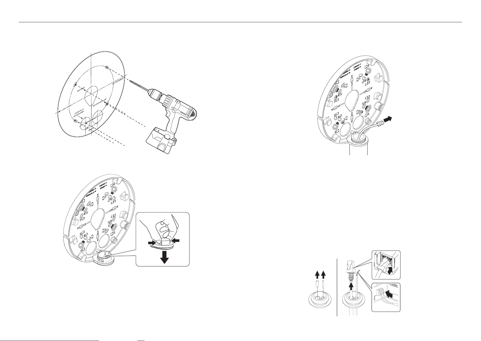
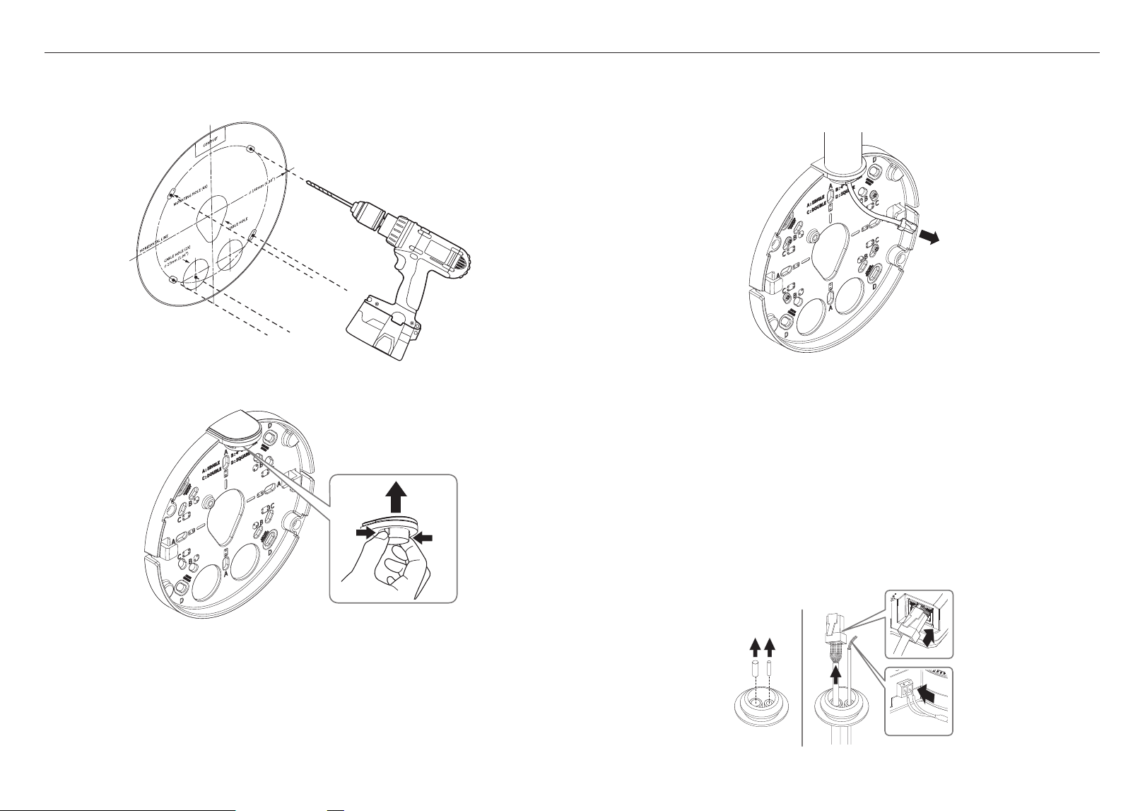
[Installing using pipe]
2-1. Attach the installation template and drill holes for screws and cables.
2-2. Separate the pipe cover of the mount plate by pressing its sides.
2-3. Place the pipe on the mount plate.
2-4. Fix the mount plate using appropriate screws.
2-5. Pull out necessary cables among network/power/audio/alarm cables through the pipe.
Installation (camera case)
J
`
Use a cable bushing compliant with the network cable to be connected.
-
Camera main: use a cable with the diameter of Ø5 to 6.5
-
Components: use a cable with the diameter of Ø5 to 8.5
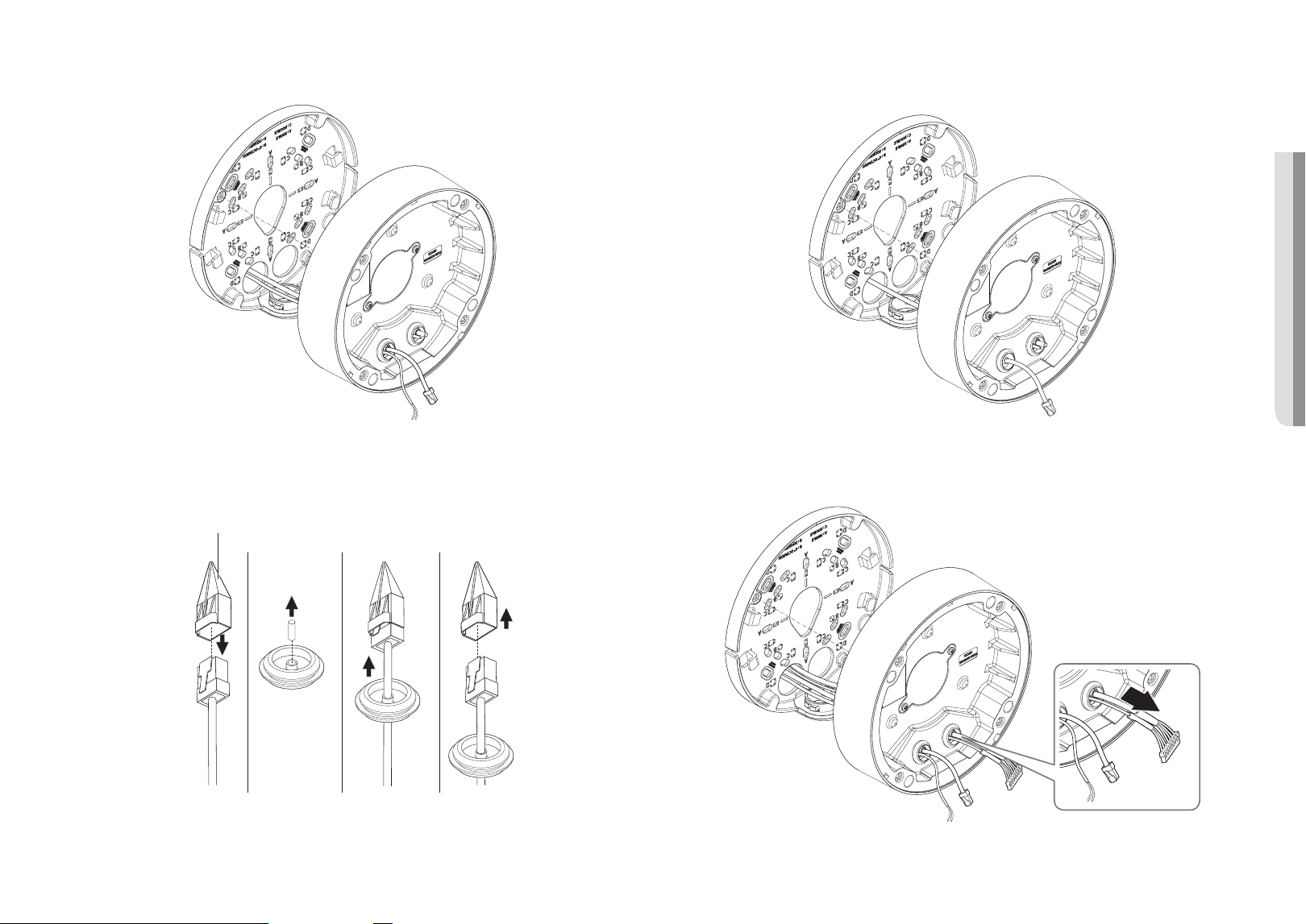
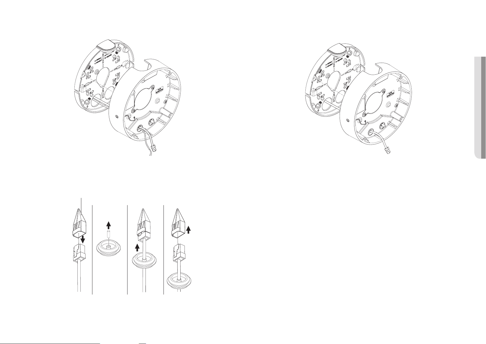
[Installing network/power cables]
1-1. Pull off the extruded parts of the cable bushing to be used.
1-2. Route the network cable through the big hole of the cable bushing and connect to the network cable
connector.
1-3. (When using the power) Route the power cable through the small hole of the cable bushing and connect
it to the provided terminal block.
PoE+
+
English _13
! VANDAL DOME CAMERA
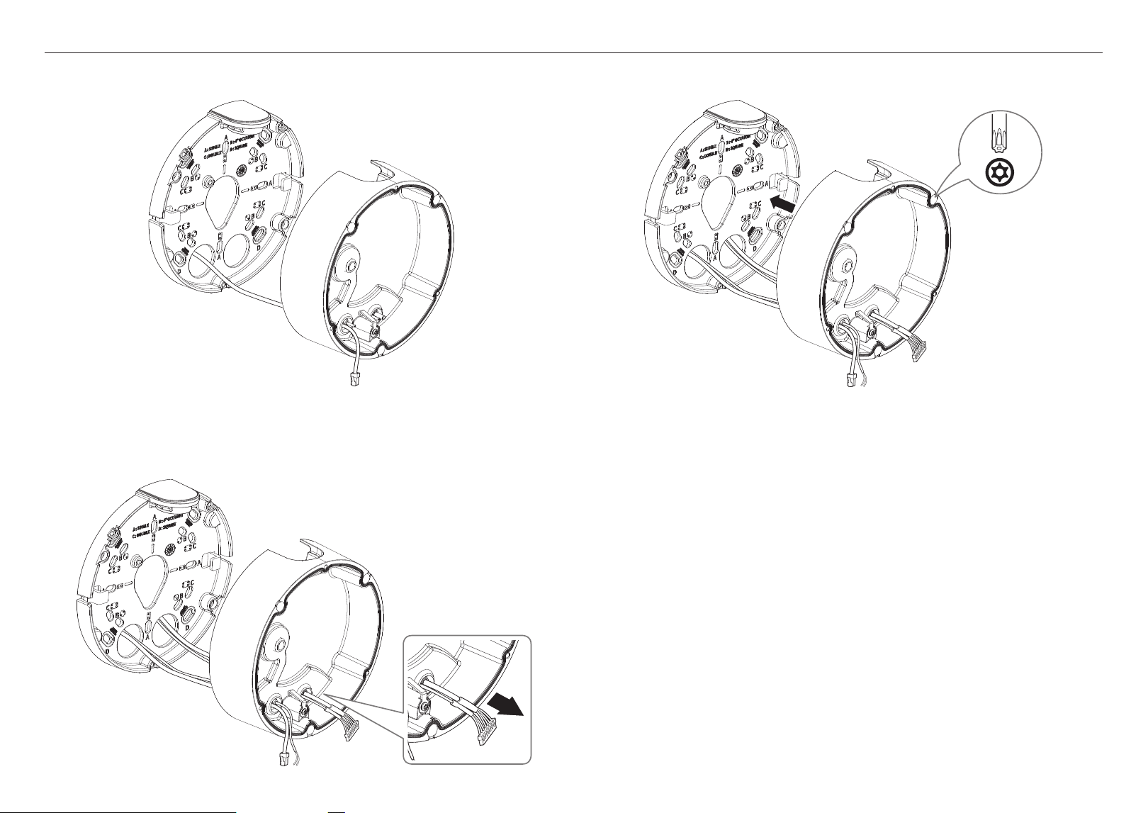
2-3. Mount the cable bushing to the camera case.
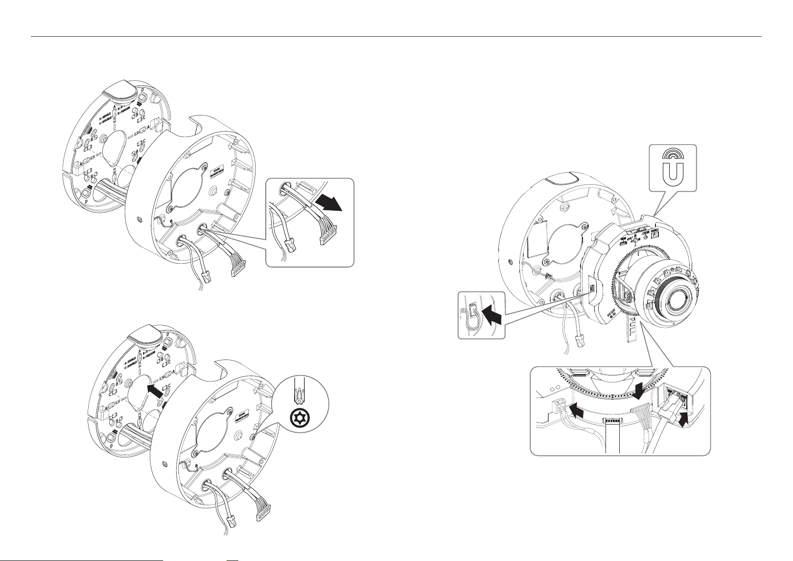
[Installing audio/alarm cables]
3-1. Mount the cable bushing of the provided audio/alarm cables to the camera case.
1-4. Mount the cable bushing to the camera case.
[Installing the network cable] (IP66)
2-1. Pull off the extruded part of the 1-hole cable bushing provided.
2-2. Use the cap installer to pass through the RJ45 cable.
Cap Installer
14_ vandal dome camera
vandal dome camera
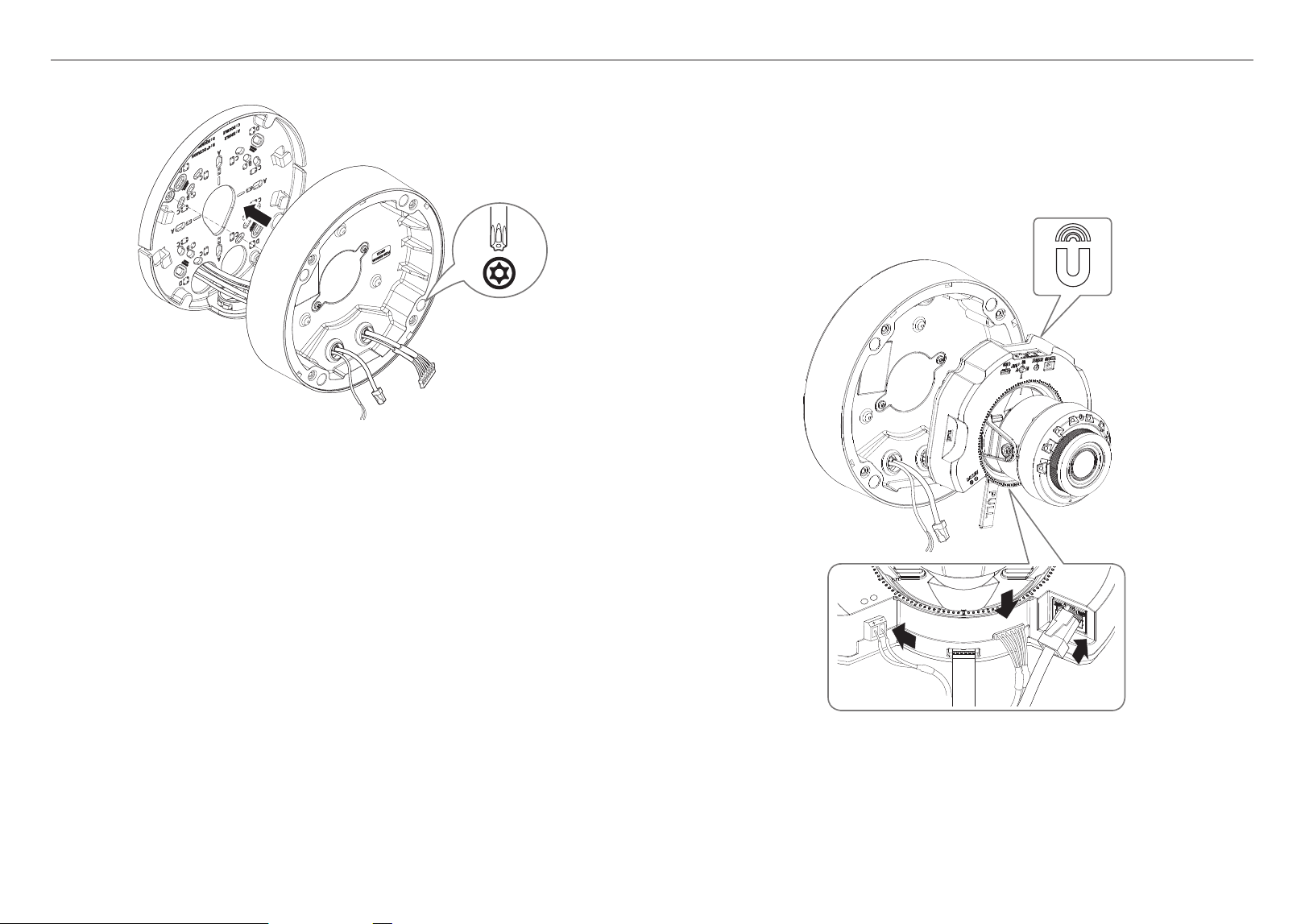
4. Join the mount plate with the camera case.
x4
2x
TR20
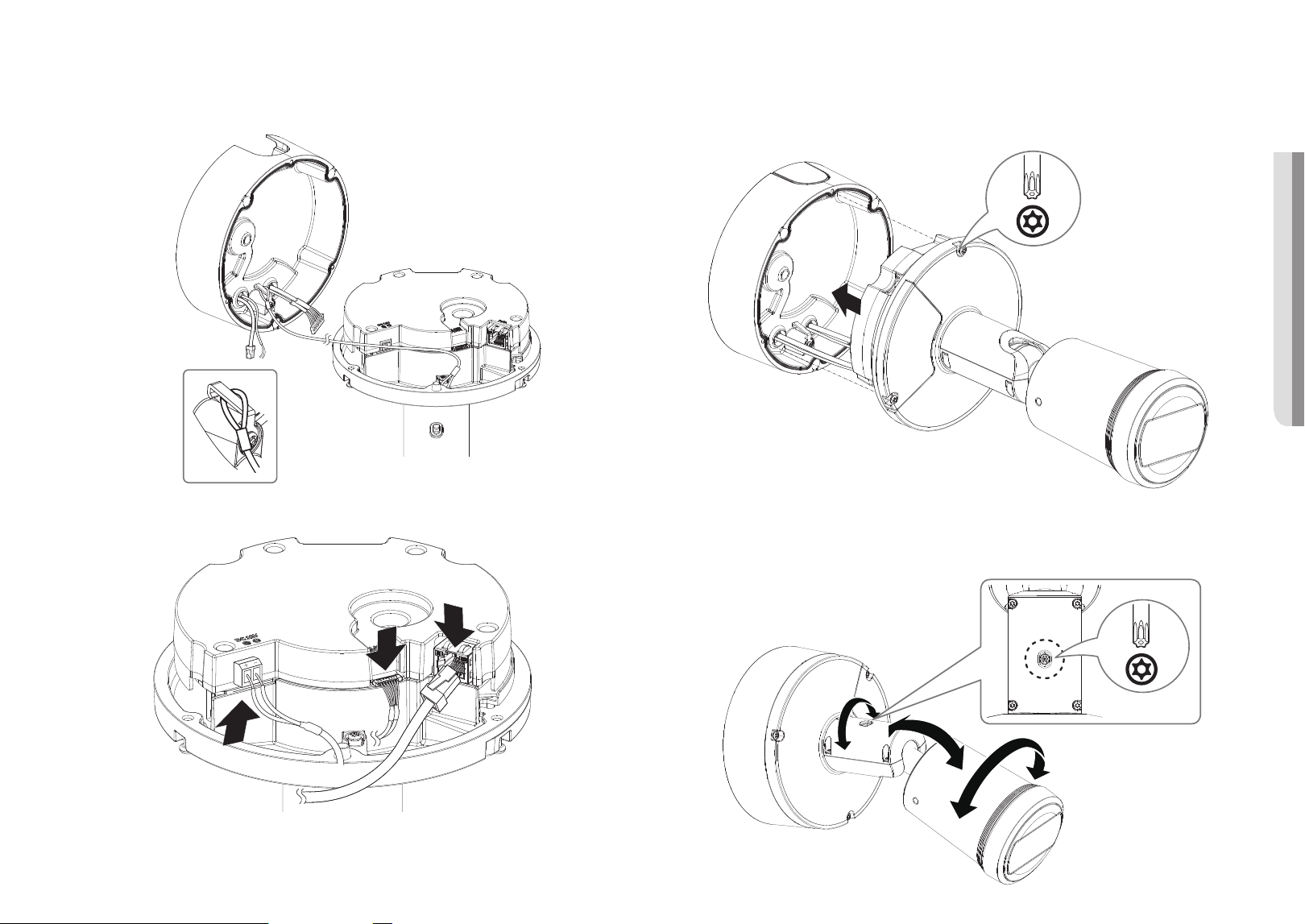
Installing the camera module
1. Connect the network/power/audio/alarm cables to the camera module terminal.
2. Attach the camera module to the case.
J
`
A magnet is embedded at the bottom of the module
`
Take caution not to allow any foreign objects between the attaching surfaces.
DC 12V
+
-
ALARM AUDIO
PULL
PoE+
3. Adjust the lens to the desired direction with reference to “Adjusting the monitoring direction for the
camera” section. (page
34)
English _15
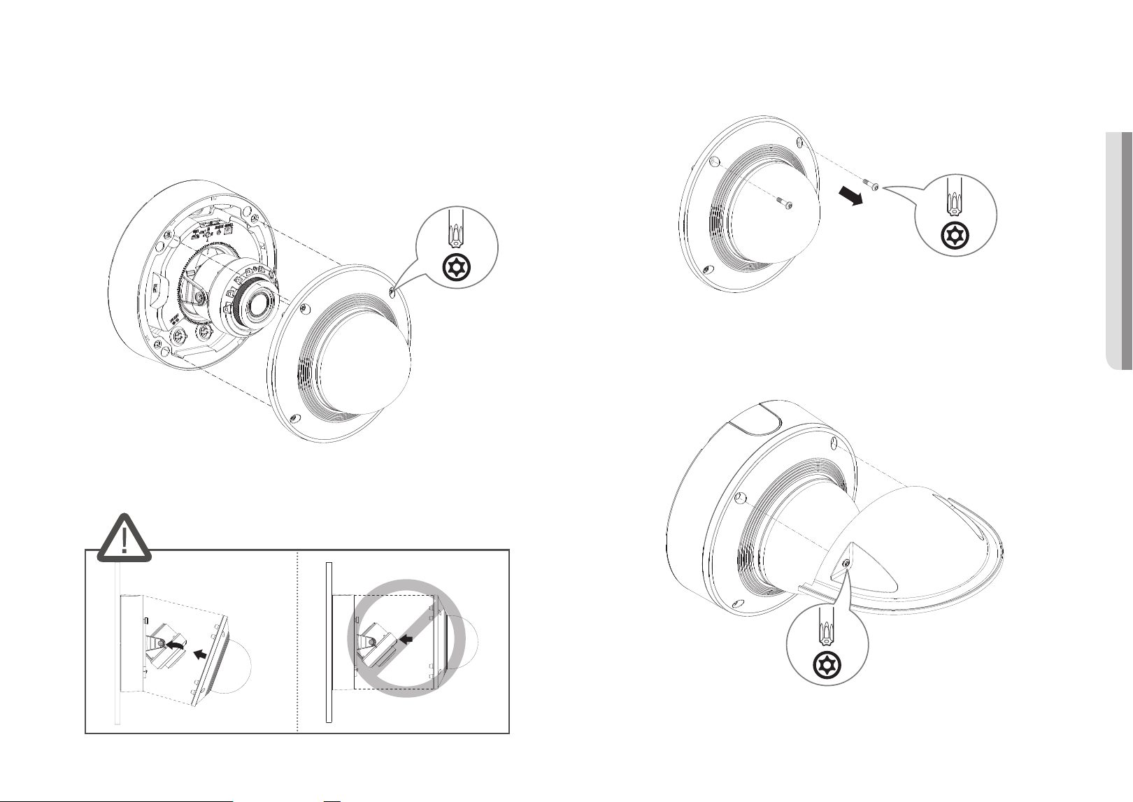
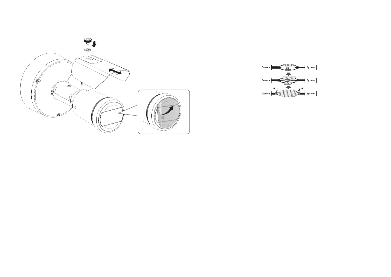
! VANDAL DOME CAMERA
[Using Weather cap]
1. Remove the screws from the dome cover.
2x
TR20
2. Assemble the dome cover.
3. Mount the weather cap to the dome cover and fasten the screws.
J
`
Make sure to firmly tighten the fastening screws so that there is no water damage issue.
2x
TR20
Assembling the dome cover
[Directly installing on wall/ceiling]
1. Assemble the dome cover.
J
`
Make sure to firmly tighten the fastening screws so that there is no water damage issue.
x4
4x
TR20
J
`
Be careful not to alter the monitoring direction of your camera.
16_ vandal dome camera
vandal dome camera
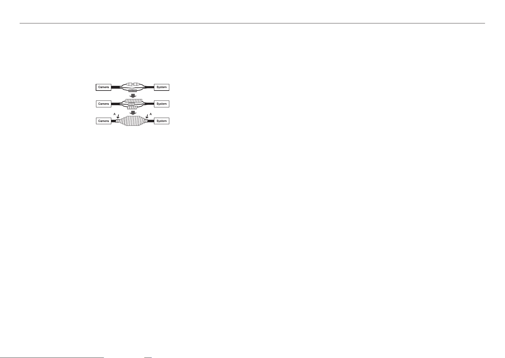
Outside installation
When you install it outside of the building, please waterproof it with waterproof butyl rubber tape (can be
purchased in stores) so that water does not leak from the gap of the cable connected to the outside.
1. Connect the power, I/O, and network cables.
2. Wrap the black cable jacket (Area A) and the cable connection area with waterproof (butyl rubber) tape so
that more than half of the butyl rubber tape is overlapped.
J
`
If the cable jacket is not waterproofed properly, then it can directly cause leakage. Make sure to protect the cable with a
dense layer of taping.
`
Waterproof butyl tape is made of butyl rubber that can be stretched to twice its normal length.
English _17
! INDOOR DOME CAMERA
WHAT’S INCLUDED
As for each sales country, accessories are not the same.
<XND-6083RV/XND-8083RV/XND-8093RV/XND-9083RV>
DC 12V
+
-
ALARM AUDIO
PoE+
PULL
Option (not included)
SBC-160B
(Color : Black)
M
`
Use installation screws of at least M4, L30 for the installation of this product.
AT A GLANCE
Mount-plate
b
Pipe-cover
a
Camera-case
c
Camera-module
d
Dome-cover
e
DC 12V
+
-
ALARM AUDIO
PULL
PoE+
h
IR LED
i
Illumination Sensor
m
Power port (DC 12 V)
o
Audio/Alarm
cable port
j
Network
Port
PoE+
VIDEO RESET W
T
N F
AF
USB
1 2
+
k
Reset button
l
Zoom/Focus
Control Button
r
Micro USB
port
q
Micro SD card slot
p
Test monitor out port
f
Internal microphone connection port
n
Separator
strap
g
Lens
indoor dome camera
18_ indoor dome camera
indoor dome camera
INSTALLATION
J
`
This camera is waterproof and in compliance with the IP52 spec, but the jack connected to the external cable is not. You are
recommended to install this product below the edge of eaves to prevent the cable from being externally exposed.
Precautions before installation
Ensure you read out the following instructions before installing the camera:
~
Select an installation site that can hold at least 5 times the camera’s weight.
~
Stuck-in or peeled-off cables can cause damage to the product or a fire.
~
For safety purposes, keep anyone else away from the installation site.
And put aside personal belongings from the site, just in case.
~
If the product is installed with excessive force, it may cause damage to the camera due to malfunction.
Forcing assembly using non-compliant tools may damage the product.
Removal
1. Peel off the fix tape and remove the dome cover, camera case, and mount plate.
2. Take off the lens cover protecting the camera lens.
DC 12V
+
-
ALARM AUDIO
PoE+
PULL
Inserting a Micro SD card
Slide the Micro SD card into the Micro SD card slot on the camera module in the direction of the arrow.
PoE+
VIDEO RESET W
T
N F
AF
USB
1 2
+
VIDEO RESET W
1 2
J
`
Before installing the camera, the Micro SD card should be inserted while the power source and the body are separated.
`
Do not forcefully insert it in the reverse direction. It might damage your Micro SD card and your product.
`
When it rains or the humidity is high, insertion or ejection of a Micro SD card is not recommended.
`
When installing/removing the Micro SD card, make sure you put the product body on a flat ground before working on it in order
to prevent accidents due to loss or drop of any parts.
English _19
! INDOOR DOME CAMERA
Removing a Micro SD card
Gently press down on the exposed end of the Micro SD card as shown in the diagram to eject the Micro SD
card from the slot.
PoE+
VIDEO RESET W
T
N F
AF
USB
1 2
+
VIDEO RESET W
1 2
J
`
Before removing the Micro SD card, in <Setup ( )>-<Event>-<Storage>, set the device to <Off> and press the [Apply]
button and turn the camera off.
`
If you turn off the camera or remove the Micro SD card that contains data from the product, the data may be lost or damaged.
Installation (mount plate)
[Directly installing on wall/ceiling]
1-1. Attach the installation template on the desired surface and drill holes for screws and cables.
1-2. Fix the mount plate using appropriate screws.
1-3. Pull out necessary cables among network/power/audio/alarm cables through the hole in the mount
plate.
20_ indoor dome camera
indoor dome camera
2-3. Place the pipe on the mount plate.
2-4. Fix the mount plate using appropriate screws.
2-5. Pull out necessary cables among network/power/audio/alarm cables through the pipe.
Installation (camera case)
J
`
Use a cable bushing compliant with the network cable to be connected.
-
Camera main: use a cable with the diameter of Ø5 to 6.5
-
Components: use a cable with the diameter of Ø5 to 8.5
[Installing network/power cables]
1-1. Pull off the extruded parts of the cable bushing to be used.
1-2. Route the network cable through the big hole of the cable bushing and connect to the network cable
connector.
1-3. (When using the power) Route the power cable through the small hole of the cable bushing and connect
it to the provided terminal block.
PoE+
+
[Installing using pipe]
2-1. Attach the installation template and drill holes for screws and cables.
2-2. Separate the pipe cover of the mount plate by pressing its sides.
English _21
! INDOOR DOME CAMERA
1-4. Mount the cable bushing to the camera case.
[Installing the network cable]
2-1. Pull off the extruded part of the 1-hole cable bushing provided.
2-2. Use the cap installer to pass through the RJ45 cable.
Cap Installer
2-3. Mount the cable bushing to the camera case.
22_ indoor dome camera
indoor dome camera
Installing the camera module
1. Connect the network/power/audio/alarm cables to the camera module terminal.
2. Attach the camera module to the case.
J
`
A magnet is embedded at the bottom of the module
`
Take caution not to allow any foreign objects between the attaching surfaces.
3. Connect the microphone cable to the camera module.
DC 12V
+
-
ALARM AUDIO
PULL
PoE+
4. Adjust the lens to the desired direction with reference to “Adjusting the monitoring direction for the
camera” section. (page
34)
[Installing audio/alarm cables]
3-1. Mount the cable bushing of the provided audio/alarm cables to the camera case.
4. Join the mount plate with the camera case.
x4
2x
TR20
English _23
! INDOOR DOME CAMERA
Assembling the dome cover
[Directly installing on wall/ceiling]
1. Assemble the dome cover.
J
`
Make sure to firmly tighten the fastening screws so that there is no water damage issue.
x4
4x
TR20
J
`
Be careful not to alter the monitoring direction of your camera.
24_ bullet camera
bullet camera
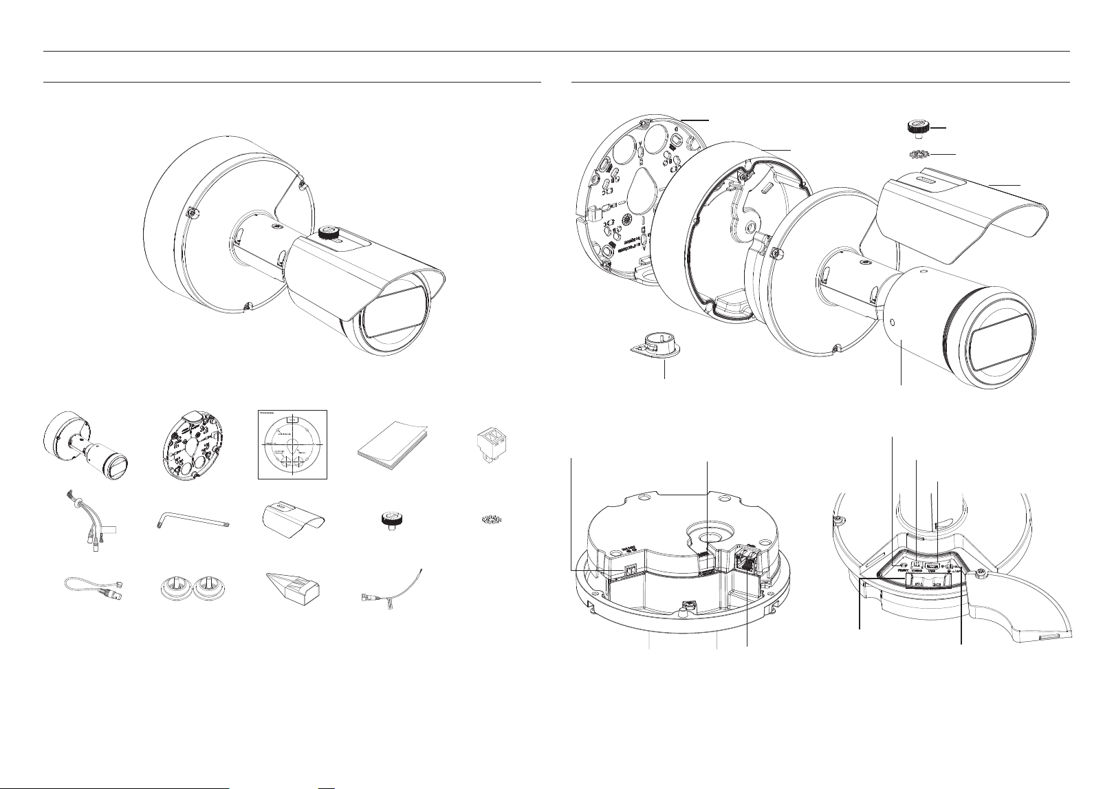
WHAT’S INCLUDED
As for each sales country, accessories are not the same.
<XNO-6083R/XNO-8083R/XNO-9083R>
M
`
Use installation screws of at least M4, L30 for the installation of this product.
AT A GLANCE
Mount plate
a
Bottom cover
b
Tooth washer
d
Camera body
g
Sunshield fixing screw
c
Pipe-cover
f
Sunshield
e
k
Reset button
i
Audio/Alarm cable
port
h
Power Port
(DC12V)
j
Network port
l
Test monitor out port
m
Micro USB port
o
Zoom/Focus
Control Button
n
Micro SD
card slot
J
`
Wipe out a dirty surface of the lens softly with a lens tissue or cloth to which you have applied ethanol.
English _25
! BULLET CAMERA
INSTALLATION
J
`
This camera is waterproof and in compliance with the IP67 spec, but the jack connected to the external cable is not. You are
recommended to install this product below the edge of eaves to prevent the cable from being externally exposed.
Precautions before installation
Ensure you read out the following instructions before installing the camera:
~
Select an installation site that can hold at least 5 times the camera’s weight.
~
Stuck-in or peeled-off cables can cause damage to the product or a fire.
~
For safety purposes, keep anyone else away from the installation site.
And put aside personal belongings from the site, just in case.
~
If the product is installed with excessive force, it may cause damage to the camera due to malfunction.
Forcing assembly using non-compliant tools may damage the product.
~
Do not use the sunshield hole for any purpose other than for connecting the sunshield.
Inserting a Micro SD card
Slide the Micro SD card into the Micro SD card slot on the camera module in the direction of the arrow.
J
`
Before installing the camera, the Micro SD card should be inserted while the power source and the body are separated.
`
Do not forcefully insert it in the reverse direction. It might damage your Micro SD card and your product.
`
When it rains or the humidity is high, insertion or ejection of a Micro SD card is not recommended.
`
When installing/removing the Micro SD card, make sure you put the product body on a flat ground before working on it in order
to prevent accidents due to loss or drop of any parts.
Removing a Micro SD card
Gently press down on the exposed end of the Micro SD card as shown in the diagram to eject the Micro SD
card from the slot.
J
`
Before removing the Micro SD card, in <Setup ( )>-<Event>-<Storage>, set the device to <Off> and press the [Apply]
button and turn the camera off.
`
If you turn off the camera or remove the Micro SD card that contains data from the product, the data may be lost or damaged.
Removal
Peel off the fix tape to remove the mount plate.
26_ bullet camera
bullet camera
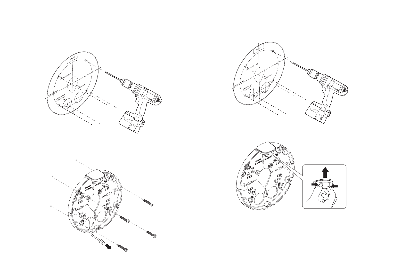
Installation (Mount plate)
[Directly installing on wall/ceiling]
1-1. Attach the installation template on the desired surface and drill holes for screws and cables.
1-2. Fix the Mount plate using appropriate screws.
1-3. Pull out necessary cables among network/power/audio/alarm cables through the hole in the Mount
plate.
[Installing using pipe]
2-1. Attach the installation template and drill holes for screws and cables.
2-2. Separate the pipe cover of the Mount plate by pressing its sides.
English _27
! BULLET CAMERA
2-3. Place the pipe on the Mount plate.
2-4. Fix the Mount plate using appropriate screws.
2-5. Pull out necessary cables among network/power/audio/alarm cables through the pipe.
Installation (Bottom cover)
J
`
Use a cable bushing compliant with the network cable to be connected.
-
Camera main: use a cable with the diameter of Ø5 to 6.5
-
Components: use a cable with the diameter of Ø5 to 8.5
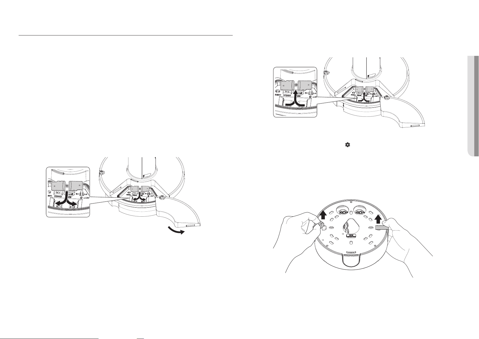
[Installing network/power cables]
1-1. Pull off the extruded parts of the cable bushing to be used.
1-2. Route the network cable through the big hole of the cable bushing and connect to the network cable
connector.
1-3. (When using the power) Route the power cable through the small hole of the cable bushing and connect
it to the provided terminal block.
1-4. Mount the cable bushing to the Bottom cover.
[Installing the network cable]
2-1. Pull off the extruded part of the 1-hole cable bushing provided.
2-2. Use the cap installer to pass through the RJ45 cable.
Cap Installer
28_ bullet camera
bullet camera
2-3. Mount the cable bushing to the Bottom cover.
[Installing audio/alarm cables]
3-1. Mount the cable bushing of the provided audio/alarm cables to the Bottom cover.
4. Join the Mount plate with the Bottom cover.
x4
3x
TR20
English _29
! BULLET CAMERA
Installing the camera module
1. Hang the safety cable up on a hook that looks like an arrow in the Bottom cover.
e.g.
2. Connect the network/power/audio/alarm cables to the camera module terminal.
3. Attach the camera body to the Bottom cover.
J
`
Make sure to firmly tighten the fastening screws so that there is no water damage issue.
x4
3x
TR20
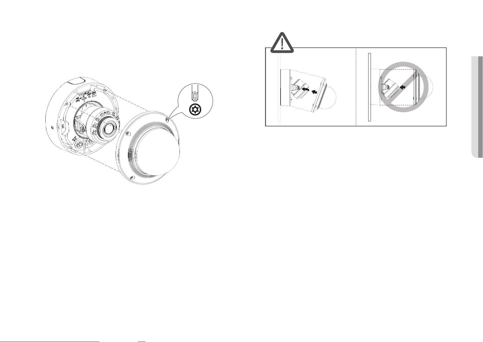
4. Adjust the camera direction using the Torx. wrench.
J
`
When you adjust the camera position using a bracket, please loosen the bracket screw, adjust the camera, and tighten it. If
you attempt to adjust it forcibly while the screw is tight, it may result in a scratch or other problems.
TR20
30_ bullet camera
bullet camera
5. Use the sunshield mounting screws and tooth washers to join the sunshield to the camera body.
Once installation is complete, peel off the protective cover from the camera lens.
Outside installation
When you install it outside of the building, please waterproof it with waterproof butyl rubber tape (can be
purchased in stores) so that water does not leak from the gap of the cable connected to the outside.
1. Connect the power, I/O, and network cables.
2. Wrap the black cable jacket (Area A) and the cable connection area with waterproof (butyl rubber) tape so
that more than half of the butyl rubber tape is overlapped.
J
`
If the cable jacket is not waterproofed properly, then it can directly cause leakage. Make sure to protect the cable with a
dense layer of taping.
`
Waterproof butyl tape is made of butyl rubber that can be stretched to twice its normal length.
English _31
! BOX CAMERA
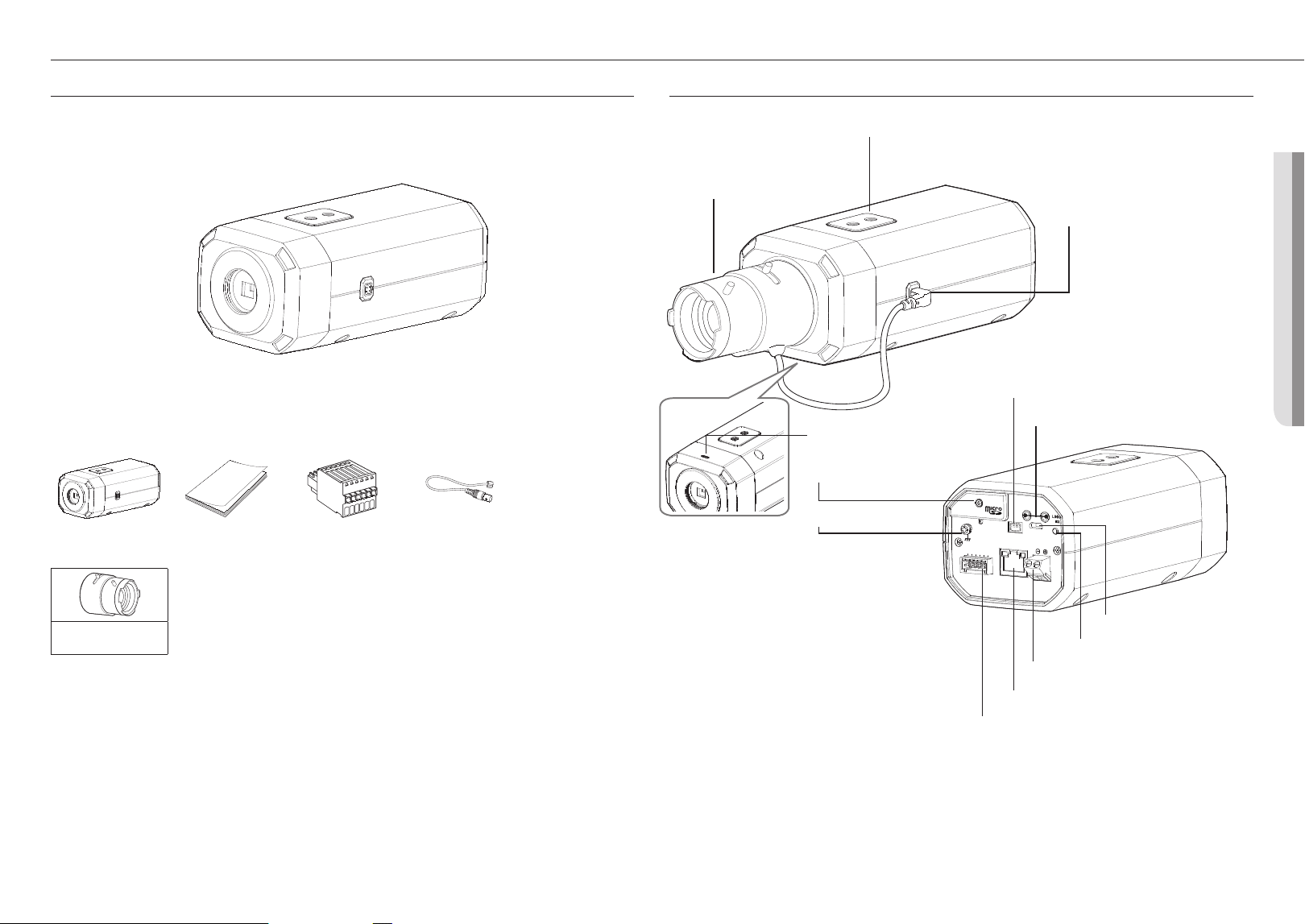
WHAT’S INCLUDED
As for each sales country, accessories are not the same.
<XNB-6003/XNB-8003/XNB-9003>
Option (not included)
CS mount Lens
box camera
AT A GLANCE
Mounting Bracket Screw Hole
b
CS mount Lens
(not included)
a
Auto Iris Lens port
c
1 : ALARM 1
2 : ALARM 2
3 : GND
4 : NC
5 : RS-485+
6 : RS-485-
2
1
3
4
5
6
RESET
VIDEO
USB
AUDIO
OUT
AUDIO
IN
FOCUS
PoE
DC 12V
Test monitor out port
m
Audio cable port
l
Micro SD card
Compartment
e
GND
f
Alarm I/O port
g
Network port
h
Power port (DC 12 V)
i
Focus button
j
Micro USB port
k
Built-in microphone
d
32_ box camera
box camera
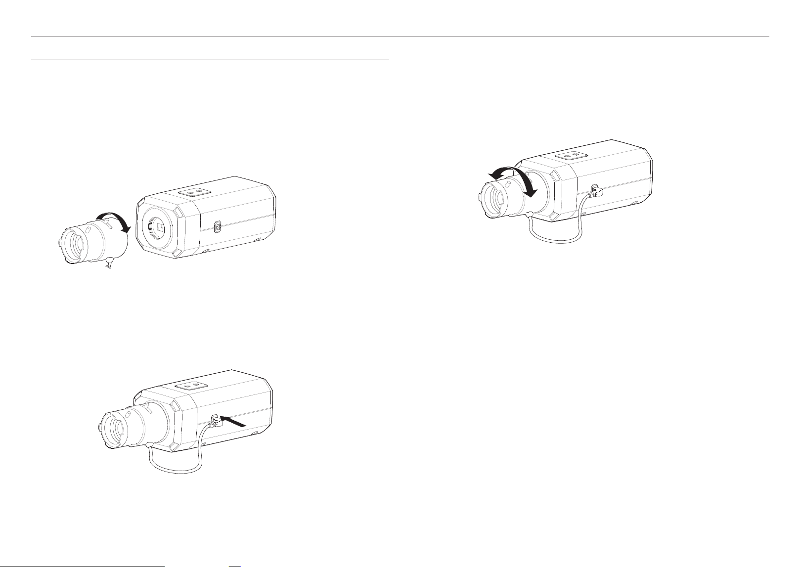
MOUNTING THE LENS
Disconnect the power before proceeding.
M
`
The CS mount Lens are not included in the product package.
It is recommended that megapixel lens are use on this camera to optimise performance.
Mounting the CS mount Lens on a camera
Turn the CS mount Lens clockwise to attach it.
CS mount Lens
Connecting the Auto Iris Lens connector
Plug the Auto Iris Lens connector of the lens in the camera connecting groove.
J
`
If the lens settings of the connected lens is different from that of the camera, the camera might not work normally.
Please plug the lens connector after changing the lens settings in the web viewer.
Focusing
Select a target to film, turn the zoom lever of the lens to adjust the magnification and then focus the lens so that
target is clearly displayed.
M
`
After focusing with the zoom lever of the lens, press the [FOCUS] button on the rear of the camera to adjust the lens even
more clearly.
`
The i-CS lens is equipped with a motor so it can be adjusted with the web viewer for zoom / focus adjustment and iris open /
close.
English _33
! BOX CAMERA
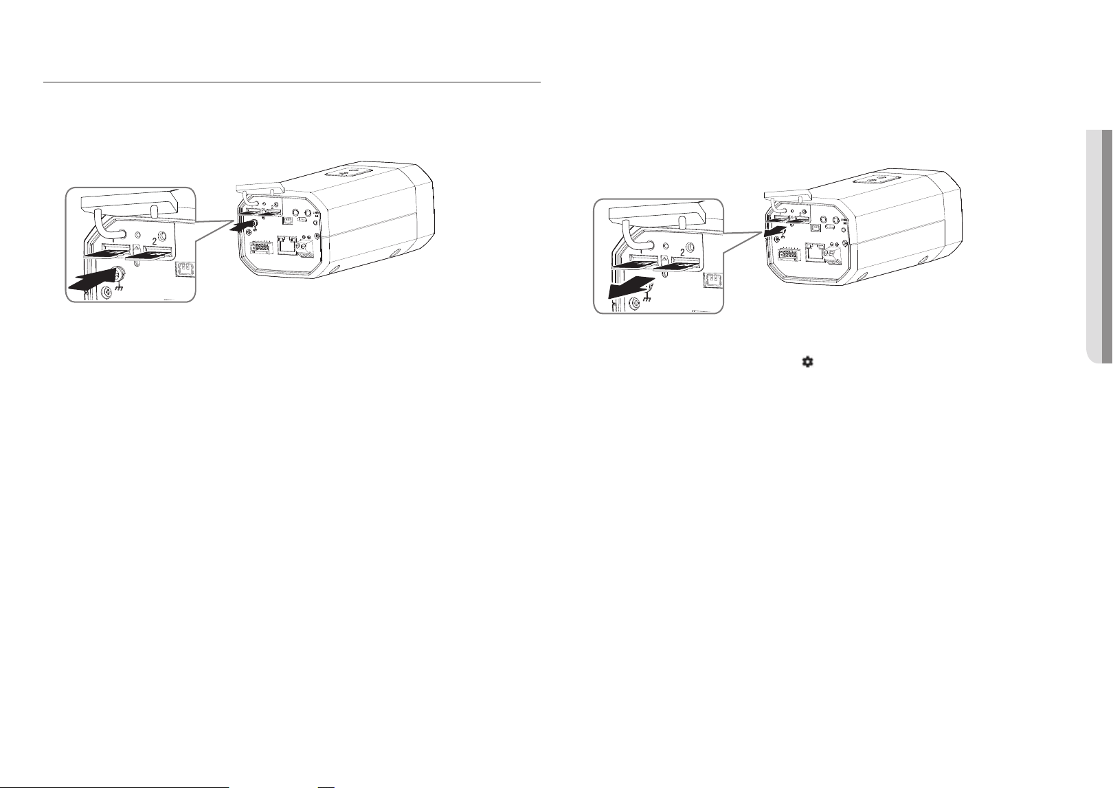
INSERTING/REMOVING A MICRO SD CARD
Inserting a Micro SD card
Insert a Micro SD card in the arrow direction shown in the figure.
RESET
VIDEO
USB
AUDIO
OUT
AUDIO
IN
FOCUS
PoE
DC 12V
1 : ALARM 1
2 : ALARM 2
3 : GND
4 : NC
5 : RS-485+
6 : RS-485-
2
1
3
4
5
6
RESET
VIDEO
AUDIO
OUT
J
`
Before installing the camera, the Micro SD card should be inserted while the power source and the body are separated.
`
Do not forcefully insert it in the reverse direction. It might damage your Micro SD card and your product.
`
When it rains or the humidity is high, insertion or ejection of a Micro SD card is not recommended.
`
When installing/removing the Micro SD card, make sure you put the product body on a flat ground before working on it in order
to prevent accidents due to loss or drop of any parts.
Removing a Micro SD card
Gently press down on the exposed end of the Micro SD card as shown in the diagram to eject the Micro SD
card from the slot.
RESET
VIDEO
USB
AUDIO
OUT
AUDIO
IN
FOCUS
PoE
DC 12V
1 : ALARM 1
2 : ALARM 2
3 : GND
4 : NC
5 : RS-485+
6 : RS-485-
2
1
3
4
5
6
RESET
VIDEO
AUDIO
OUT
J
`
Before removing the Micro SD card, in <Setup ( )>-<Event>-<Storage>, set the device to <Off> and press the [Apply]
button and turn the camera off.
`
If you turn off the camera or remove the Micro SD card that contains data from the product, the data may be lost or damaged.
34_ installation & connection
installation & connection
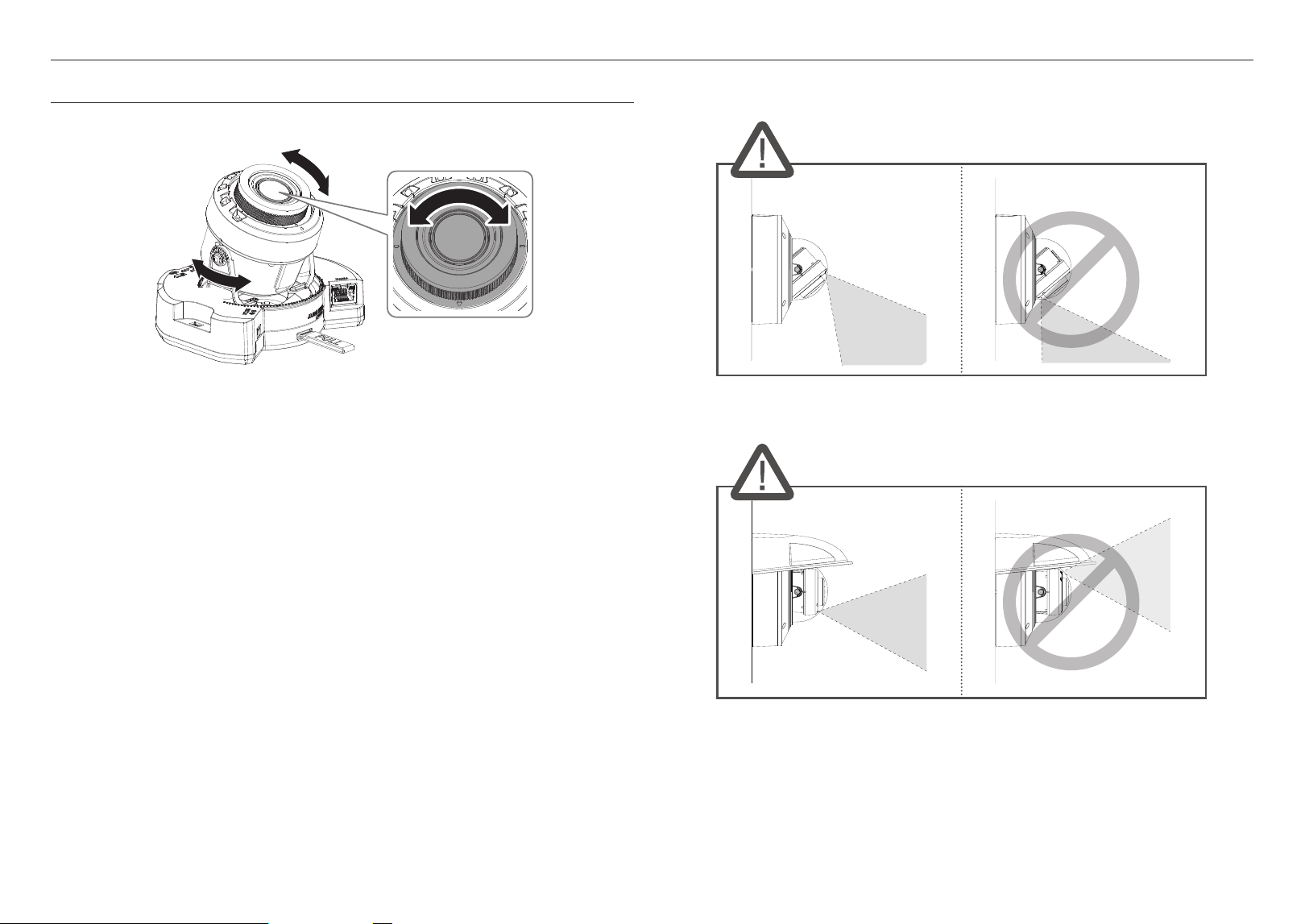
ADJUSTING THE MONITORING DIRECTION FOR THE CAMERA
Pan
Lens rotation
Tilt
`
Adjusting the monitoring direction
You can adjust the camera direction only when the camera is fixed on the ceiling.
At this time, rotating the main body of the camera in the left and right direction is called PAN, and adjusting
the angle of the camera is called TILT.
- The pan angle is 0˚ – 360˚.
- The tilt angle is -45˚ – 85˚.
- The rotation angle is 0˚ – 355˚.
J
`
In 75˚ or more tilt angle, a blockage of view or burred image may occur in some part of the screen depending on the
zoom magnification.
`
Do not forcefully rotate or press the focus/zoom lens. Otherwise, the focus might not work properly due to motor failure.
`
Methods of adjustment
1. Adjust the pan angle taking account of the direction to monitor.
2. Adjust the horizontal angle so that the video does not flip when rotated.
3. Adjust the tilt angle toward the direction to monitor.
J
`
Adjust the direction of IR LEDs not to hinder their view by an instrument.
J
`
Adjust the direction of IR LEDs not to hinder their view by a weather cap (if any).
English _35
! INSTALLATION & CONNECTION
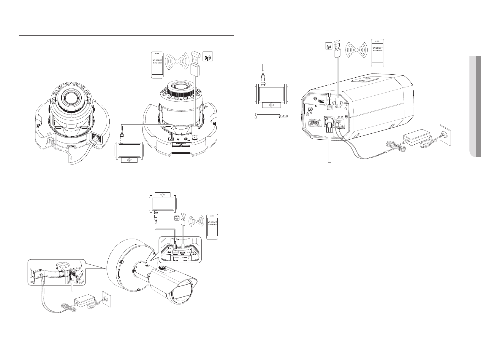
CONNECTING WITH OTHER DEVICE
<XNV-6083R/XNV-8083R/XNV-8093R/XNV-9083R/XND-6083RV/XND-8083RV/XND-8093RV/XND-9083RV>
PoE+
VIDEO RESET W
T
N F
AF
USB
1 2
+
DC 12V
+
-
ALARM AUDIO
PULL
PoE+
SOFT
AP
Ethernet
Monitor for installation
Power
WiFi dongle
<XNO-6083R/XNO-8083R/XNO-9083R>
Ethernet
Power
WiFi dongle
Monitor for installation
<XNB-6003/XNB-8003/XNB-9003>
RESET
VIDEO
USB
AUDIO
OUT
AUDIO
IN
FOCUS
PoE
DC 12V
1 : ALARM 1
2 : ALARM 2
3 : GND
4 : NC
5 : RS-485+
6 : RS-485-
2
1
3
4
5
6
SOFT
AP
Monitor for installation
Ethernet
Grounding cable
Power
WiFi dongle
J
`
The Test Monitor Out port of the product is provided for easier installation, and is not recommended for monitoring purposes.
`
The Micro USB port of the product is provided for easier installation, and is not recommended for monitoring purposes.
installation & connection
36_ installation & connection
Ethernet Connection
Connect the Ethernet cable to the local network or to the Internet.
Connecting WiFi
Camera Setup
1. Connect OTG adapter (5-pin) and WiFi dongle to the micro USB port.
Smartphone Setup
1. Install the Wisenet Installation application.
2. Select the camera SSID after turning on the WiFi.
3. Run the Wisenet Installation application.
4. When you log in to the camera, the video will be connected.
`
The video will be played without being logged in during the initial connection.
5. You can adjust angle of view while watching the video through smartphone.
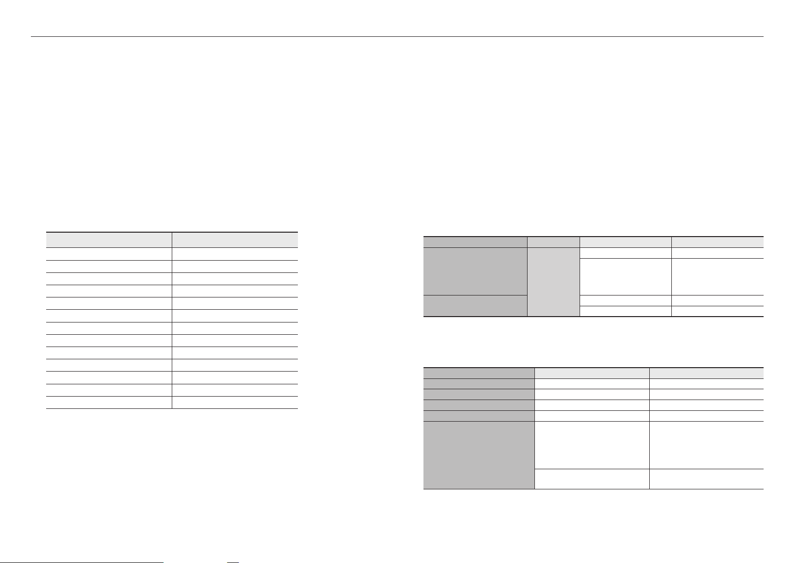
Recommended dongle manufacturer
Manufacturer Model
NETIS WF2123 n300
EDIMAX
EW-7811Un V2(New ver.)
IP Time N100mini
IP Time N105L
TP-LINK TL-WN823N V1
TP-LINK TL-WN725N
TP-LINK T2U Nano
ASUS USB-N13
ASUS USB-N10 NANO
NETGEAR WNA3100M
IODATA WN-G150UMW
IODATA WN-S150UM
TOTOLINK N300UM
Power Supply
Use the screwdriver to connect each line (+, –) of the power cable to the corresponding power port of the
camera.
J
`
If the power sources for PoE+ and DC 12 V are simultaneously turned on, the device power will be supplied by both of PoE+
and DC 12 V. (
XNV-6083R/XNV-8083R/XNV-8093R/XNV-9083R/XND-6083RV/XND-8083RV/XND-8093RV/XND-9083RV/
XNO-6083R/XNO-8083R/XNO-9083R)
`
When both PoE and DC 12V power sources are used, the device is powered by external power source (DC12V).
(XNB-6003/XNB-8003/XNB-9003)
`
If you are connecting using a router that supports PoE or PoE+, you do not need to use a separate power supply.
`
Use PoE that is compliant with the IEEE 802.3at protocols. (XNV-6083R/XNV-8083R/XNV-8093R/XNV-9083R/XND-6083RV/
XND-8083RV/XND-8093RV/XND-9083RV/XNO-6083R/XNO-8083R/XNO-9083R)
`
Use PoE that is compliant with the IEEE 802.3af protocols. (XNB-6003/XNB-8003/XNB-9003)
`
If you want to connect an external device, you must turn off the external device before proceeding.
`
Connect the set and the adapter power line first, and then connect the power cable to the outlet on the wall.
Power Cable Specification for Each Model
Model Input power Wire Type (AWG) Cable Length (Max.)
XND-6083RV/XND-8083RV/
XND-8093RV/XND-9083RV/
XNV-6083R/XNV-8083R/
XNV-8093R/XNV-9083R/
XNB-6003/XNB-8003/XNB-9003
DC 12V
#18
12m
#16 20m
XNO-6083R/XNO-8083R/
XNO-9083R
#20 12m
#18 19m
J
`
Be careful not to reverse the polarity when you connect the power cable.
Network Cable Specification
Item Contents Remark
Connector RJ-45(10/100/1000BASE-T)
Ethernet 10/100/1000BASE-T
Cable Category 6
Max Distance 100 m
PoE Support
PoE+
(XNV-6083R/XNV-8083R/XNV-8093R/
XNV-9083R/XND-6083RV/XND-8083RV/
XND-8093RV/XND-9083RV/XNO-6083R/
XNO-8083R/XNO-9083R)
PoE
(XNB-6003/XNB-8003/XNB-9003)
English _37
! INSTALLATION & CONNECTION
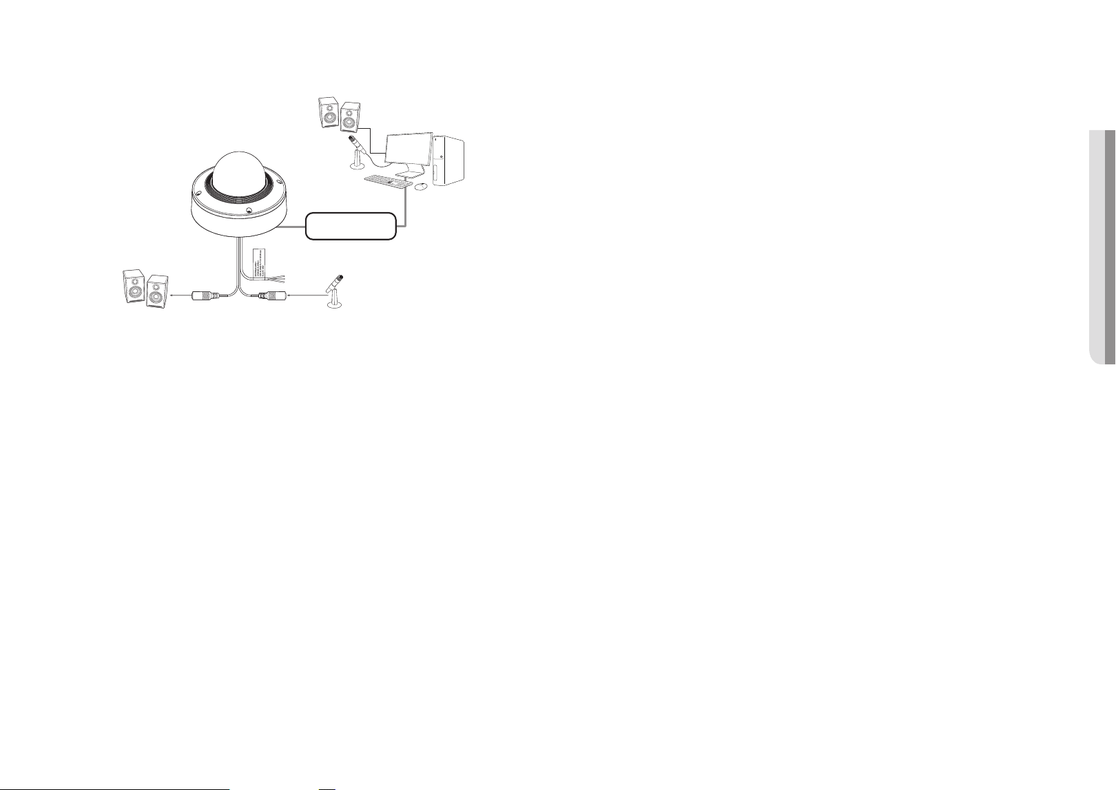
Connecting to Audio Input/Output
Network
PC
Microphone
Speaker
Microphone
Speaker
1. Connect the
MIC port of the camera with the microphone or LINE OUT port of the amplifier that the
microphone is connected to.
M
`
You can use the internal microphone of the camera without an external microphone connection
(only applicable for
XND-6083RV/XND-8083RV/XND-8093RV/XND-9083RV/XNB-6003/XNB-8003/XNB-9003).
2. Connect the SPEAKER port of the camera with the speaker or LINE IN port of the amplifier that the
speaker is connected to.
3. Check the specifications for audio input.
~
Audio Codec
- Audio In : G.711 PCM (Bit Rate: 64kbps / Sampling Frequency: 8kHz), G.726 ADPCM (Bit Rate:
16Kbps, 24Kbps, 32Kbps, 40Kbps / Sampling Frequency: 8kHz), AAC (Bit Rate: 48Kbps / Sampling
Frequency: 16kHz)
- Audio Out : G.711 PCM (Bit Rate: 64kbps / Sampling Frequency: 8kHz)
~
Full duplex Audio
~
Audio in
(XND-6083RV/XND-8083RV/XND-8093RV/XND-9083RV/XNB-6003/XNB-8003/XNB-9003) :
Selectable (microphone/Line-in/Built-in microphone), Supported voltage: 2.5VDC (4mA), Input impedance:
2K Ohm
~
Audio in (XNV-6083R/XNV-8083R/XNV-8093R/XNV-9083R/XNO-6083R/XNO-8083R/XNO-9083R) :
Selectable (microphone/Line-in), Supported voltage: 2.5VDC (4mA), Input impedance: 2K Ohm
~
Audio out : Line-out (3.5mm mono jack), Maximum output: 1Vms, Line out impedance : 600Ω
J
`
In the case you access the web viewer and select an external microphone as the audio input sources in <Video & Audio> -
<Audio setup>, the following specifications are recommended:
-
Frequency range: 40-16,000 Hz
-
Impedance: 1,500 Ω
-
Sensitivity: -40±3 dB (7.1-14.1 mV)
`
In any of the following cases, sound classification performance may be degraded or malfunction:
-
If gunshot sounds are heard continuously in a short interval (e.g. machine gun sound) rather than a one-time gunshot
sound
-
If the noise is too loud for the noise and the target sound to be distinguished
-
If two or more of different sounds are registered simultaneously
-
If the sound classification is applied while using the noise removal function in a quiet place
-
If the source of clapping sounds or screams is close to the camera (within 1 meter)
-
If a sound that does not belong to any of the sound classification categories (airplanes sound, siren sound, etc.) is loudly
heard all of sudden
-
If external microphone does not meet the recommended specifications
installation & connection
38_ installation & connection
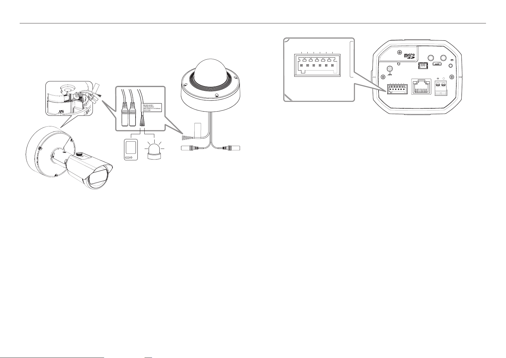
Connecting to the I/O port box
Connect the Alarm I/O cable to the corresponding port of the port box.
<XNV-6083R/XNV-8083R/XNV-8093R/XNV-9083R/XND-6083RV/XND-8083RV/
XND-8093RV/XND-9083RV/XNO-6083R/XNO-8083R/XNO-9083R>
Sensor
Alarm
(Warning lamp)
~
ALARM 1, ALARM 2 : These ports can be used as alarm input or output ports. If used as input ports,
alarm input or day/night sensors can be connect to them. If used as output ports,
alarm output signals can be connect to them.
※
Alarm I/O changes can be made through the Webviewer setup.
~
ALARM OUT(DC12/50mA) : Used to connect the alarm output signal.
~
GND : Common port for alarm in/output signal.
J
`
If devices (e.g., flashing light and siren) that exceed the voltage and current specifications are connected by using the open
collector method, it may cause malfunction.
Refer to the “Alarm Out Wiring Diagram” when connecting devices that exceed the voltage and current specifications. (page 39)
<XNB-6003/XNB-8003/XNB-9003>
RESET
AUDIO
OUT
AUDIO
IN
USB
VIDEO
LINK
FOCUS
PoE
DC 12V
+
1 : ALARM 1
2 : ALARM 2
3 : GND
4 : NC
5 : RS-485+
6 : RS-485-
1 2 3 4 5 6
1 : ALARM 1
2 : ALARM 2
3 : GND
4 : NC
5 : RS-485+
6 : RS-485-
1 2 3 4 5 6
~
ALARM 1, ALARM 2 : These ports can be used as alarm input or output ports. If used as input ports,
alarm input or day/night sensors can be connect to them. If used as output ports,
alarm output signals can be connect to them.
※
Alarm I/O changes can be made through the Webviewer setup.
~
GND : Used for earth-grounding.
~
RS-485+ : Communication port for RS-485 receiver (+).
~
RS-485- : Communication port for RS-485 receiver (–).
Connecting an external RS-485 device
By connecting an external device to the [RS-485 +, –] port, the external device can be controlled.
`
The GND connection is recommended for RS-485 communications. If you encounter a communication failure, connect the GND pin
as appropriate to correct the GND level between camera and external device.
English _39
! INSTALLATION & CONNECTION
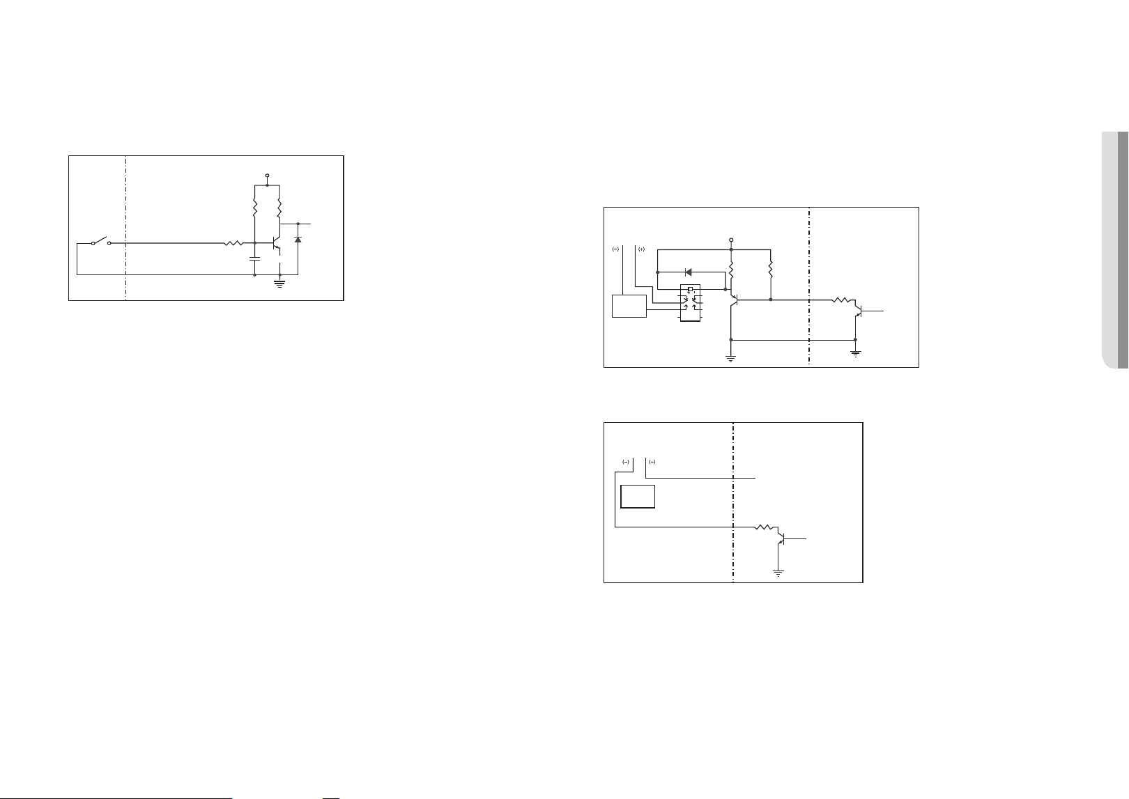
To connect the external sensor
Connect one of the 2 signal lines to the [
ALARM 1] port (if you want this to be the input port) and the
remaining one to the [GND] port.
Alarm In Wiring Diagram
Sensor
GND
RESISTORALARM 1(5 mA SINK)
RESISTOR RESISTOR
VCC_3.3V
DIODE
GND
MLCC
TRANSISTOR
External
connection
Inside of the camera
To connect the alarm out
If devices (e.g., flashing light and siren) that exceed the voltage and current specifications are connected by
using the open collector method, it may cause malfunction.
Refer to the alarm out connection diagram below when connecting devices that exceed the voltage and
current specifications.
Alarm Out Wiring Diagram
When the warning light/siren exceeds DC12V/50mA
Warning lamp /
Siren power
Warning lamp /
Siren
ALARM 2
RESISTOR 10K ohm
DIODE
RELAY
DC 5V or 3.3V
TRANSISTOR
GND
GND
TRANSISTOR
External connection Inside of the camera
GND
RESISTOR
When the warning light/siren does not exceed DC12V/50mA
(only applicable for XNV-6083R/XNV-8083R/XNV-8093R/XNV-9083R/XND-6083RV/XND-8083RV/XND-
8093RV/XND-9083RV/XNO-6083R/XNO-8083R/XNO-9083R)
Warning lamp /
Siren power
ALARM 2 DC 12 V/50 mA MAX
ALARM Out DC 12 V/50 mA MAX
TRANSISTOR
External connection Inside of the camera
GND
RESISTOR
Warning lamp /
Siren
network connection and setup
40_ network connection and setup
network connection and setup
You can set up the network settings according to your network configurations.
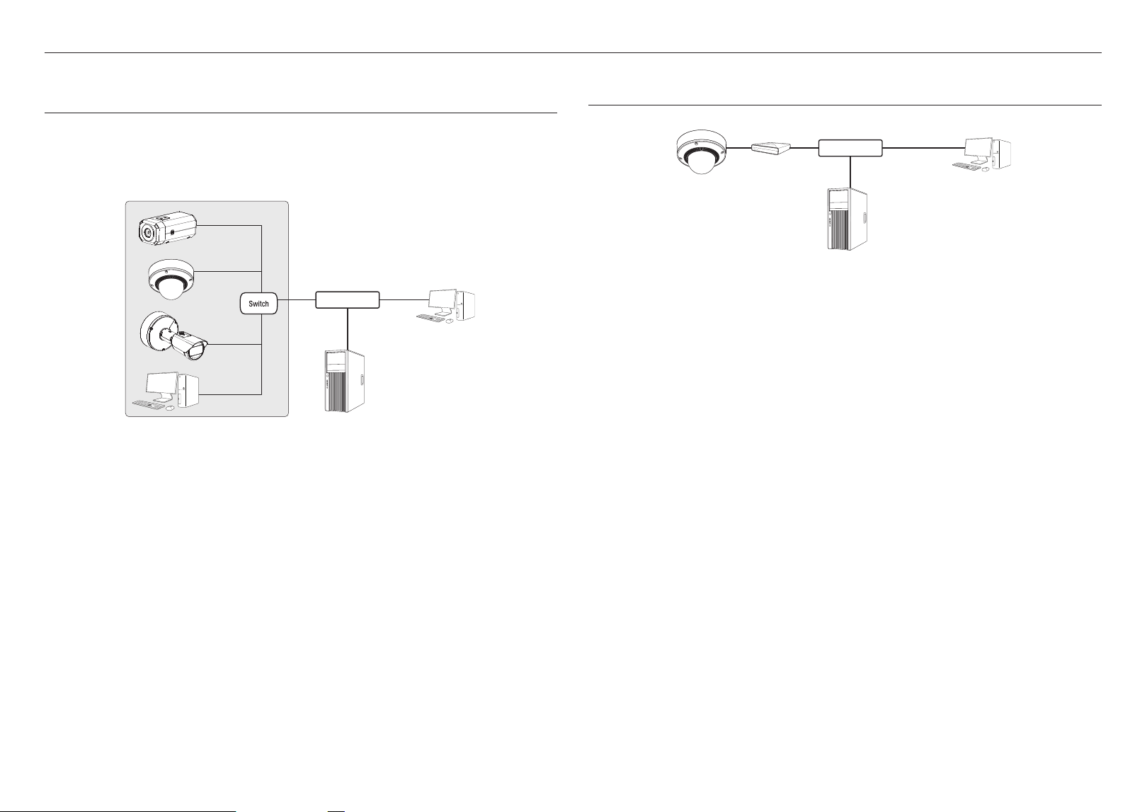
CONNECTING THE CAMERA DIRECTLY TO LOCAL AREA NETWORKING
Connecting to the camera from a local PC in the LAN
1. Launch an Internet browser on the local PC.
2. Enter the IP address of the camera in the address bar of the browser.
<
>
Camera
Camera
Local PC
Camera
INTERNET
External Remote PC
DDNS Server
(Data Center, KOREA)
<Local Network>
M
`
A remote PC in an external Internet out of the LAN network may not be able to connect to the camera installed in the intranet
if the port-forwarding is not properly set or a firewall is set.
In this case, to resolve the problem, contact your network administrator.
`
By factory default, the IP address will be assigned from the DHCP server automatically.
If there is no DHCP server available, the IP address will be set to 192.168.1.100.
To change the IP address, use the Device Manager.
For further details on Device Manager use, refer to “Using Device Manager”. (Page 41)
CONNECTING THE CAMERA DIRECTLY TO A DHCP BASED DSL/CABLE
MODEM
1. Connect the user PC directly with the network camera.
2. Run the Device Manager and change the IP address of the camera so that you can use the web browser
on your desktop to connect to the camera.
3. Use the Internet browser to connect to the web viewer.
4. Move to [Setup] page.
5. Move to [Network] – [DDNS] and configure the DDNS settings.
6. Move to [Basic] – [IP & Port], and set the IP type to [DHCP].
7. Connect the camera, which was removed from your PC, directly to the modem.
8. Restart the camera.
M
`
For information on how to set DDNS, refer to the online help of Web Viewer.
`
For information on how to set the IP format, refer to the online help of Web Viewer.
Camera
External Remote PC
DDNS Server
(Data Center, KOREA)
DSL/Cable Modem
INTERNET
English _41
! NETWORK CONNECTION AND SETUP
USING DEVICE MANAGER
M
`
Device manager program can be downloaded from <Technical Support>-<Online Tool> menu at Hanwha Techwin website
(http://www.hanwha-security.com).
`
More instructions of Device Manager can be found at <Help> menu of the main page.
AUTOMATICALLY SEARCHING CAMERA
If a camera is connected to the same network of the PC where device manager is installed, you
can find network camera by using search function.
1. Click <Search> at the main page of device manager.
2. Check the camera from the list.
~
Check MAC address at the sticker attached to the camera.
CONFIGURING IP ADDRESS
If you want to change camera network setting, <Login OK> sign must be displayed at <Status>.
Click <Authentication> at the main page to log in.
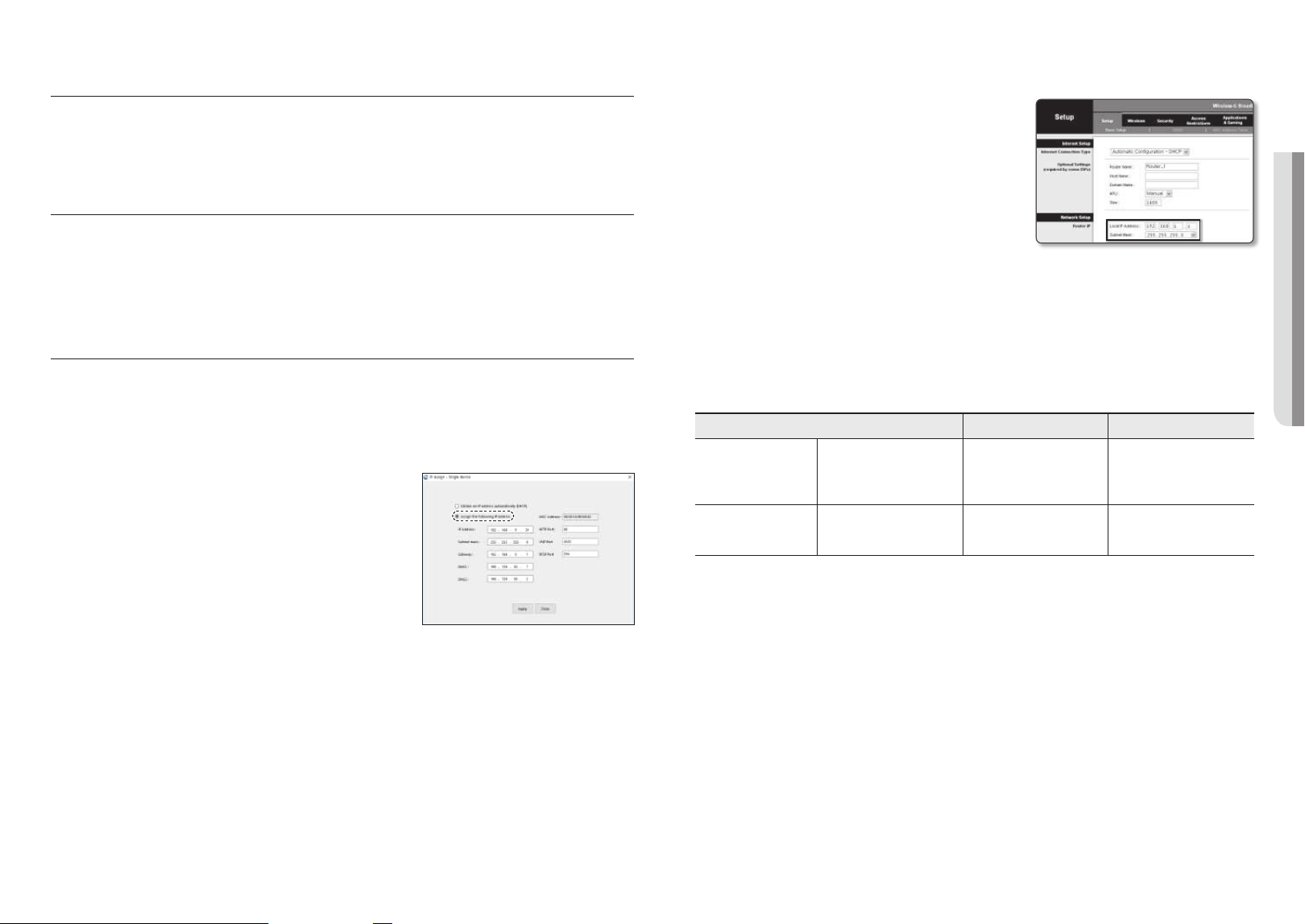
Configuring Static IP
Manually insert and configure IP address & port information.
1. Click the camera from the list that you want the change the
IP setting.
2. Click <IP Assign> at the main page of device manager.
3. Select <Assign the following IP address>.
~
IP information of the camera will be displayed as previously
set.
4. Fill in IP & Port related categories.
If not using a Broadband Router
For setting <IP Address>, <Subnet Mask>, and <Gateway>, contact your network administrator.
~
HTTP Port : Used to access the camera using the Internet browser, defaulted to 80.
~
RTSP Port: A port that controls real-time streaming. The initial value is 554.
If using a Broadband Router
~ IP Address : Enter an address falling in the IP range provided
by the Broadband Router.
ex) 192.168.1.2~254, 192.168.0.2~254,
192.168.XXX.2~254
~
Subnet Mask : The <Subnet Mask> of the Broadband Router
will be the <Subnet Mask> of the camera.
~
Gateway : The <Local IP Address> of the Broadband Router
will be the <Gateway> of the camera.
M
`
The settings may differ depending on the connected Broadband Router model.
For more information, refer to the user manual of the applicable router.
`
For more information about port forwarding of the broadband router, refer to “Port Range Forward (Port Mapping) Setup”.
(Page
43)
If the Broadband Router has more than one camera connected
Configure the IP related settings and the Port related settings distinctly with each other.
ex)
Category Camera #1 Camera #2
IP related settings
IP Address
Subnet Mask
Gateway
192.168.1.100
255.255.255.0
192.168.1.1
192.168.1.101
255.255.255.0
192.168.1.1
Port related settings
HTTP Port
RTSP Port
8080
554
8081
555
M
`
If the <HTTP Port> is set other than 80, you must provide the <Port> number in the address bar of the Internet browser
before you can access the camera.
ex) http://IP address : HTTP Port
http://192.168.1.100:8080
5. Click [Apply] Button.
6. If the success message is displayed, click [OK].
network connection and setup
42_ network connection and setup
Configuring Dynamic IP
Receive IP address from DHCP
~
Example of the Dynamic IP environment
- If a Broadband Router, with cameras connected, is assigned an IP address by the DHCP server
- If connecting the camera directly to modem using the DHCP protocols
- If IPs are assigned by the internal DHCP server via the LAN
1. Click the camera from the list that you want to change the IP
setting.
2. Click <IP Assign> at the main page of device manager.
3. Select <Obtain an IP address automatically (DHCP)>.
4. Click [Apply] button.
5. If the success message is displayed, click [OK].
MANUALLY REGISTERING CAMERA
If the camera cannot be found using search function, the camera can be registered remotely by
manually inserting IP information, if the camera is connected to external network.
1. Click <Add Devices> - <Manually Add Device> at the main
page of device manager.
2. Insert the range of IP address that you search.
3. Select the <Model Name> of the camera that you register,
and insert HTTP port, ID, and password.
4. Click [Register] button.
5. Check if camera is registered.
~
Check MAC address at the sticker attached to the camera.
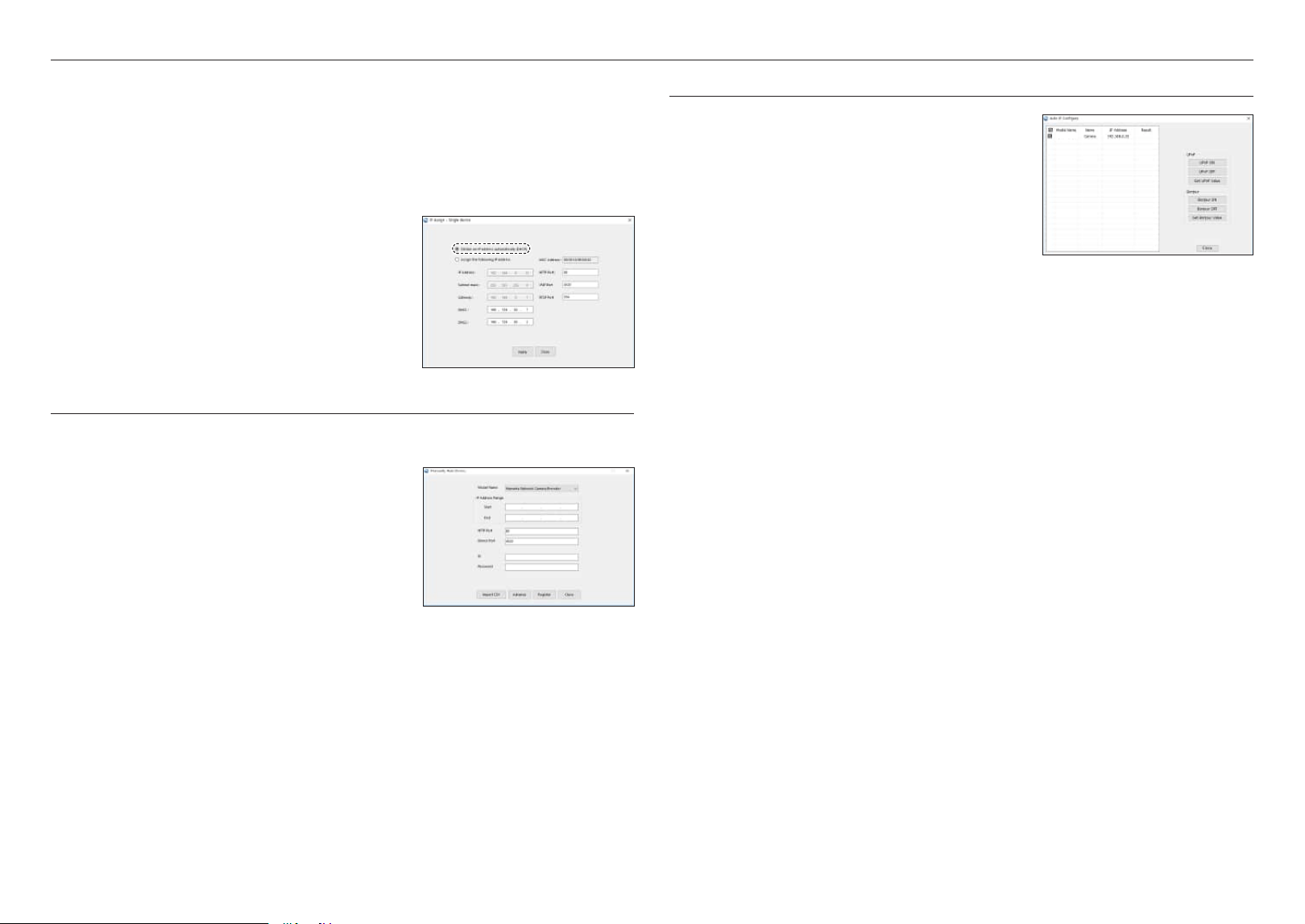
AUTOMATICALLY CONFIGURING IP
1. Click the camera from the list that you want to automatically
configure the IP.
2. Click < + > at the main page of device manager.
~
Equipment Setting menu appears.
3. At the menu, click <Auto IP Configure>.
4. Click [Close] button.
XNO-9083R
English _43
! NETWORK CONNECTION AND SETUP
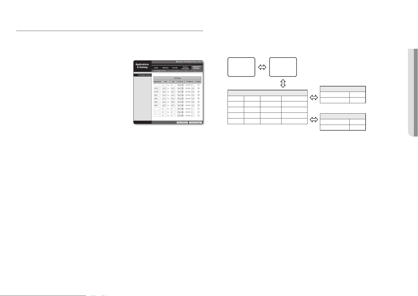
PORT RANGE FORWARD (PORT MAPPING) SETUP
If you have installed a Broadband Router with a camera connected, you must set the port range forwarding on the
Broadband Router so that a remote PC can access the camera in it.
Manual Port Range Forwarding
1. From the Setup menu of the Broadband Router, select
<Applications & Gaming> - <Port Range Forward>.
For setting the port range forward for a third-party Broadband
Router, refer to the user guide of that Broadband Router.
2. Select <TCP> and <UDP Port> for each connected camera
to the Broadband Router.
The number of each port to be configured to the IP router
should be set according to the port number designated
in <Setup> - <Basic> - <IP & Port> on the camera web
viewer.
3. When done, click [Save Settings].
Your settings will be saved.
M
`
Port forwarding setting is an example of setting CISCO IP router.
`
The settings may differ depending on the connected Broadband Router model.
For more information, refer to the user manual of the applicable router.
Setting up Port Range Forward for several network cameras
~
You can set a rule of Port Forwarding on the Broadband Router device through its configuration web page.
~
A user can change each port using the camera setting screen.
When Camera1 and Camera2 are connected to a router :
User
Internet
Broadband Router
Start End Protocol IP Address
3000 3000 TCP/UDP 192.168.1.100
3001 3001 TCP/UDP 192.168.1.101
8080 8080 TCP/UDP 192.168.1.100
8081 8081 TCP/UDP 192.168.1.101
Camera1 (192.168.1.100)
HTTP port 8080
RTSP port 3000
Camera2 (192.168.1.101)
HTTP port 8081
RTSP port 3001
M
`
Port forwarding can be done without additional router setup if the router supports the UPnP (Universal Plug and Play) function.
After connecting the network camera, select the checkbox from the menu <Quick connect> in <Wisenet DDNS> in
“Settings -> Network -> DDNS”.

network connection and setup
44_ network connection and setup
CONNECTING TO THE CAMERA FROM A SHARED LOCAL PC
1. Run device manager.
It will scan for connected cameras and display them as a list.
2. Double-click a camera to access.
The Internet browser starts and connects to the camera.
M
`
Access to the camera can also be gained by typing the camera’s IP address in the address bar of the Internet browser.
CONNECTING TO THE CAMERA FROM A REMOTE PC VIA THE
INTERNET
On a remote computer that is not in the Broadband Router’s network cluster is not allowed, users can access
cameras within a Broadband Router’s network by using the camera’s DDNS URL.
1. Before you can access a camera in the Broadband Router network, you should have set the port range
forward for the Broadband Router.
2. From the remote PC, launch the Internet browser and type the DDNS URL address of the camera, or the
IP address of the Broadband Router in the address bar.
ex) http://ddns.hanwha-security.com/ID
M
`
To use Wisenet DDNS, sign up at the Wisenet DDNS homepage (http://ddns.hanwha-security.com) and register the product
at [My DDNS]>[Register Product].
English _45
! WEB VIEWER
web viewer
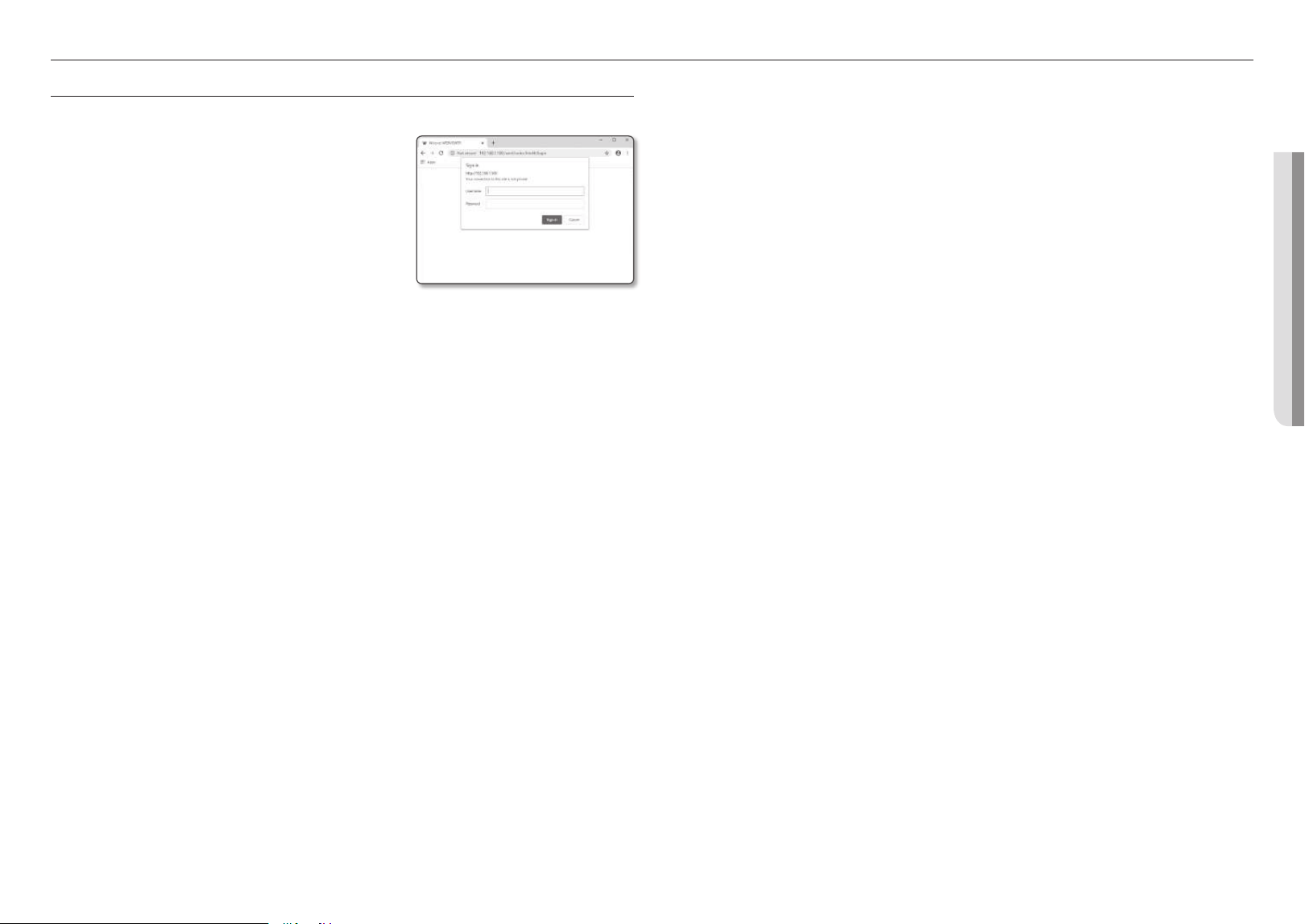
CONNECTING TO THE CAMERA
Normally, you would
1. Launch the Internet browser.
2. Type the IP address of the camera in the address bar.
ex)
~
IP address (IPv4) : 192.168.1.100
;
http://192.168.1.100
- the Login dialog should appear.
~
IP address (IPv6) : 2001:230:abcd: ffff:0000:0000:ffff:1111
;
http://[2001:230:abcd:ffff:0000:0000:ffff:1111] - the Login
dialog should appear.
If the HTTP port is other than 80
1. Launch the Internet browser.
2. Type the IP address and HTTP port number of the camera in the address bar.
ex) IP address : 192.168.1.100:HTTP Port number(8080)
;
http://192.168.1.100:8080 - the Login dialog should appear.
Using URL
1. Launch the Internet browser.
2. Type the DDNS URL of the camera in the address bar.
ex) URL address : http://ddns.hanwha-security.com/ID
- the Login dialog should appear.
J
`
Network connection is disabled in the LAN only environment.
Connecting via UPnP
1. Run the client or operating system in support of the UPnP protocol.
2. Click the camera name for search.
In the Windows operating system, click the camera name searched from the network menu.
- The login window is displayed.
Connecting via Bonjour
1. Run the client or operating system in support of the Bonjour protocol.
2. Click the camera name for search.
In the Mac operating system, click the camera name searched from the Bonjour tab of Safari.
- The login window is displayed.
To check the DDNS address
If the camera is connected directly to a DHCP-based cable modem or DSL modem, the IP address will
change each time it tries to connect to the ISP (the company you subscribed to).
If this is the case, you will not be informed of the IP address changed by DDNS.
Once you register a dynamic IP-based device with the DDNS server, you can easily check the changed IP
when you try to access the device.
To register your device to the <DDNS> server, visit http://ddns.hanwha-security.com and register your device
first, and then set the Web Viewer’s <Network> - <DDNS> to <Wisenet DDNS>, as well as providing
<Product ID> that had been used for DDNS registration.
web viewer
46_ web viewer
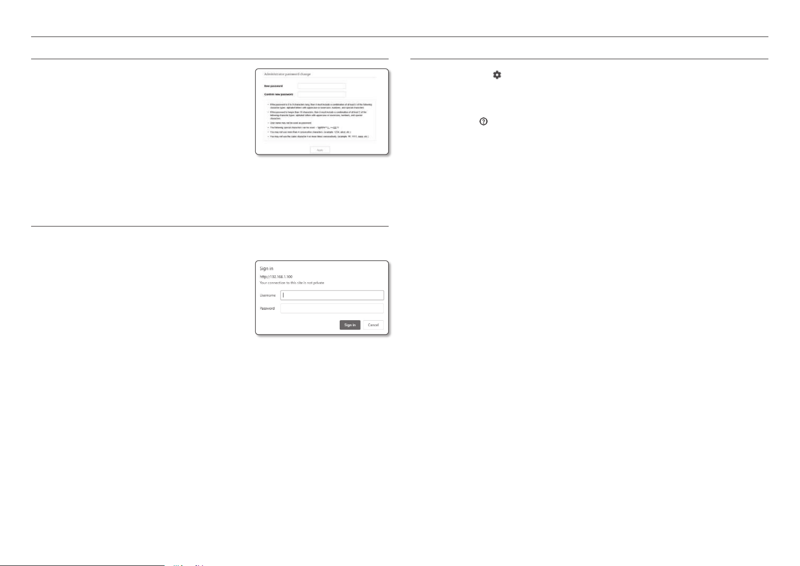
PASSWORD SETTING
When you access the product for the first time, you must register the
login password.
J
`
For a new password with 8 to 9 digits, you must use at least 3 of
the following: uppercase/lowercase letters, numbers and special
characters. For a password with 10 to 15 digits, you must use at
least 2 types of those mentioned.
-
Special characters that are allowed. : ~`!@#$%^*()_-+=|{}[].?/
`
For higher security, you are not recommended to repeat the same
characters or consecutive keyboard inputs for your passwords.
`
If you lost your password, you can press the [RESET] button to initialize the product. So, don’t lose your password by using a
memo pad or memorizing it.
LOGIN
Whenever you access the camera, the login window appears.
Enter the User ID and password to access the camera.
1. Enter “admin” in the <User name> input box.
The administrator ID, “admin”, is fixed and can not be
changed.
2. Enter the password in the <Password> input field.
3. Click [Sign in].
If you have logged in successfully, you will the Live Viewer
screen.
J
`
When you access the camera web viewer, pay special attention to the
security by checking whether the image data is encrypted.
M
`
You will experience the best video quality if the screen size is 100%. Reducing the ratio may cut the image on the borders.
CAMERA WEB VIEWER SETUP
1. Click the [Setup (
)] icon.
2. The Settings window appears.
3. You can configure settings for the camera’s basic information, video, audio, network, event, analysis, and
system over the network.
4. Click <Help (
)> to view detailed descriptions of each function.
English _47
! APPENDIX
appendix
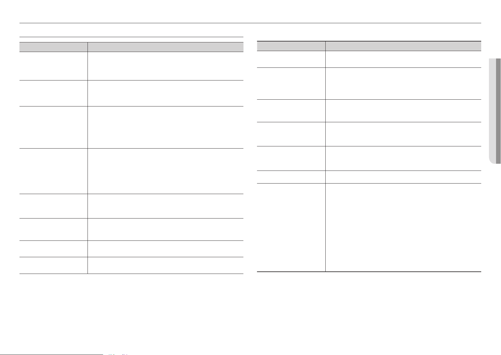
TROUBLESHOOTING
PROBLEM SOLUTION
When an Windows 10 user accesses
the web viewer through Chrome
or Firefox, the sound volume of
microphone changes periodically.
~
This is what happens when microphone driver has been set to Realtek driver.
Install the High Definition Audio device (Windows Default Driver) or the third party driver as
the microphone driver.
What are the specifications for WAVE
files necessary to play audio at the
time of an event?
~
Sampling rate of 48,000 KHz or less is recommended.
~
For bits per sample (bps), up to 8/16 bit is recommended.
~
Only PCM encoding format is supported.
No video is displayed when accessing
the plug-in free webviewer on Safari
via HTTPS.
~
On the authentication popup window prompted when initially accessing https, click "View
Authentication Certificate" and select the "Always trust when connecting to the designated
webviewer IP" check box.
~
If the webviewer continues failing to display a video after you select "Next" on the message
window below, press the command key + Q to exit the Safari browser, access again and
follow the procedures stated above.
I can’t access the camera from a web
browser.
~
Check to make sure that the camera’s Network settings are appropriate.
~
Check to make sure that all network cables have been connected properly.
~
If connected using DHCP, verify that the camera is able to acquire dynamic IP addresses
without any problem.
~
If the camera is connected to a Broadband Router, verify that port forwarding is properly
configured.
Viewer got disconnected during
monitoring.
~
Connected Viewers become disconnected upon any change to camera or network
configurations.
~
Check all network connections.
The camera connected to the network
is not detected in the Device Manager
program.
~
Turn off the firewall settings on your PC and then search the camera again.
Images overlap.
~
Check whether two or more cameras are set to a single multicast address instead of different
addresses. If a single address is used for multiple cameras, the images may overlap.
No image appears.
~
If the transmission method is set to multicast, check whether there is a router that supports
multicast in the LAN the camera is connected to.
PROBLEM SOLUTION
Voice is not recorded even though
audio input settings are configured.
~
You must enable the <Audio In> check box in <Basic> - <Video Profile>.
<Motion detection> of <Analytics> is
set to <Enable>, but no notification
e-mail reaches me even when an
analysis event had occurred.
~
Verify the settings in the following sequence:
A. Check <Data & Time> settings.
B. The <Motion detection> should be set to <Enable>.
C. Check if the <E-mail> option of <Event setup> menu is checked to use.
No signal is found at the Alarm Output
port even when an intelligent video
analysis event is generated.
~
Check alarm output port settings.
Cannot record into the Micro SD card.
~
Check if the memory card is defective.
~
When replacing the Micro SD card, it must be done while the power is disconnected from
the product.
Micro SD card is inserted but the
camera does not operate properly.
~
Check if the Micro SD card is inserted in the proper direction. Operation of Micro SD card that
is formatted by other devices is not guaranteed with this camera unit.
~
Format the Micro SD card again in <Setup>
;
<Event>
;
<Storage> menu.
Cannot record in the NAS.
~
Confirm that the information registered in the NAS is correct.
It reports that NAS setting has failed.
~
Confirm that the IP address of the NAS is valid.
~
Confirm that the ID/password of the NAS is valid.
~
Confirm that you can access the folder designated as the default folder using the ID of the
NAS.
~
Confirm that the NAS SMB/CIFS items are unchecked.
~
Confirm that the NAS IP address and the camera IP address are in the same format.
ex) The NAS & camera subnet mask initial value is 255.255.255.0.
If the IP address is 192.168.20.32 then the NAS IP address should be in the range of
192.168.20.1~192.168.20.255.
~
Check whether you tried to access as another user without formatting the default folder
saved or used.
~
Confirm that you used recommended NAS equipment.
Any changes or modifications in construction of this device which are not expressly approved by the
party responsible for compliance could void the user's authority to operate the equipment.
This device complies with part 15 of the FCC Rules. Operation is subject to the following two
conditions: (1) This device may not cause harmful interference, and (2) this device must accept any
interference received, including interference that may cause undesired operation.
This equipment has been tested and found to comply with the limits for a Class A digital device,
pursuant to part 15 of the FCC Rules. These limits are designed to provide reasonable protection
against harmful interference when the equipment is operated in a commercial environment.
This equipment generates, uses, and can radiate radio frequency energy and, if not installed and used
in accordance with the instruction manual, may cause harmful interference to radio communications.
Operation of this equipment in a residential area is likely to cause harmful interference in which case
the user will be required to correct the interference at his own expense.
Correct disposal of batteries in this product
(Applicable in the European Union and other European countries with separate battery return systems.)
This marking on the battery, manual or packaging indicates that the batteries in this product should not be disposed of with other
household waste at the end of their working life. Where marked, the chemical symbols Hg, Cd or Pb indicate that the battery contains
mercury, cadmium or lead above the reference levels in EC Directive 2006/66. If batteries are not properly disposed of, these
substances can cause harm to human health or the environment.
To protect natural resources and to promote material reuse, please separate batteries from other types of waste and recycle them
through your local, free battery return system.
Correct Disposal of This Product (Waste Electrical & Electronic Equipment)
(Applicable in the European Union and other European countries with separate collection systems)
This marking on the product, accessories or literature indicates that the product and its electronic accessories (e.g.
charger, headset, USB cable) should not be disposed of with other household waste at the end of their working life.
To prevent possible harm to the environment or human health from uncontrolled waste disposal, please separate
these items from other types of waste and recycle them responsibly to promote the sustainable reuse of material
resources.
Household users should contact either the retailer where they purchased this product, or their local government
office, for details of where and how they can take these items for environmentally safe recycling.
Business users should contact their supplier and check the terms and conditions of the purchase contract. This
product and its electronic accessories should not be mixed with other commercial wastes for disposal.
Hanwha Techwin cares for the environment at all product manufacturing stages, and is taking measures to provide
customers with more environmentally friendly products.
The Eco mark represents Hanwha Techwin's devotion to creating environmentally friendly products, and indicates
that the product satisfies the EU RoHS Directive.