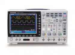

Mixed-Domain Oscilloscope
MDO-2000E Series
USER MANUAL
ISO-9001 CERTIFIED MANUFACTURER

April 2019
This manual contains proprietary information, which is protected by
copyright. All rights are reserved. No part of this manual may be
photocopied, reproduced or translated to another language without
prior written consent of Good Will company.
The information in this manual was correct at the time of printing.
However, Good Will continues to improve products and reserves the
rights to change specification, equipment, and maintenance
procedures at any time without notice.
Good Will Instrument Co., Ltd.
No. 7-1, Jhongsing Rd., Tucheng Dist., New Taipei City 236, Taiwan

TABLE OF CONTENTS
1
Table of Contents
SAFETY INSTRUCTIONS .................................................. 4
GETTING STARTED .......................................................... 9
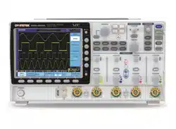
MDO-2000E Series Overview ..................................... 10
Appearance ................................................................ 14
Set Up ....................................................................... 28
Built-in Help .............................................................. 37
MEASUREMENT ............................................................ 38
Basic Measurement ................................................... 39
Automatic Measurement ............................................ 46
Cursor Measurement ................................................. 60
Math Operation ......................................................... 67
ADVANCED CONFIGURATION ....................................... 77
Acquisition ................................................................ 80
Segmented Memory Acquisition ................................ 85
Display ...................................................................... 97
Horizontal View ........................................................102
Vertical View (Channel) .............................................110
Bus Key Configuration ..............................................118
Trigger ......................................................................143
Search.......................................................................183
System Settings and Miscellaneous Settings ............192
LOGIC ANALYZER ......................................................... 197
Logic Analyzer Operation ..........................................198
ARBITRARY WAVE GENERATOR .................................... 213
Arbitrary Wave Generator Operation .........................214

MDO-2000E series User Manual
2
SPECTRUM ANALYZER ................................................. 247
Spectrum Analyzer operation ................................... 248
DMM ............................................................................ 265
DMM function ......................................................... 266
POWER SUPPLY ............................................................ 275
Power supply function ............................................. 276
APPLICATIONS ............................................................. 279
Introduction ............................................................. 280
Go-NoGo application ............................................... 282
DVM application ...................................................... 287
Data Log application ................................................ 289
Digital Filter application .......................................... 291
Mask application ..................................................... 293
SAVE/RECALL ............................................................... 303
File Format/Utility ................................................... 304
Create/Edit Labels .................................................... 310
Save ......................................................................... 313
Recall ....................................................................... 321
Reference Waveforms ............................................... 327
FILE UTILITIES ............................................................. 329
File Navigation ........................................................ 330
Create Folder ........................................................... 331
Rename File ............................................................. 332
Delete File or Folder ................................................ 333
Copy File to USB ...................................................... 334
HARDCOPY KEY ........................................................... 335
REMOTE CONTROL CONFIG ........................................ 339
Interface Configuration ............................................ 340

TABLE OF CONTENTS
3
MAINTENANCE ............................................................ 350
FAQ .............................................................................. 356
APPENDIX .................................................................... 358
Updating the Firmware .............................................359
MDO-2000E Series Specifications .............................361
Probe Specifications .................................................368
Dimensions ..............................................................370
Declaration of Conformity .........................................371
INDEX .......................................................................... 372
MDO-2000E series User Manual
4
SAFETY INSTRUCTIONS
This chapter contains important safety
instructions that you must follow during
operation and storage. Read the following before
any operation to insure your safety and to keep
the instrument in the best possible condition.
Safety Symbols
These safety symbols may appear in this manual or on the Product
name.
WARNING
Warning: Identifies conditions or practices that
could result in injury or loss of life.
CAUTION
Caution: Identifies conditions or practices that
could result in damage to the equipment or to
other properties.
DANGER High Voltage
(Note)
Attention required
Refer to the Manual
Protective Conductor Terminal
Earth (ground) Terminal

SAFETY INSTRUCTIONS
5
Do not dispose electronic equipment as unsorted
municipal waste. Please use a separate collection
facility or contact the supplier from which this
instrument was purchased.
Safety Guidelines
General Guideline
WARNING
CAUTION
Make sure the BNC input voltage does not
exceed 300Vrms.
Never connect a hazardous live voltage to the
ground side of the BNC connectors. It might
lead to fire and electric shock.
Do not place any heavy object on the MDO-
2000E series.
Avoid severe impact or rough handling that
leads to damaging the MDO-2000E series.
Do not discharge static electricity to the MDO-
2000E series.
Use only mating connectors, not bare wires, for
the terminals.
Do not block the cooling fan opening.
Do not perform measurement at a power source
or building installation (Note below).
Do not disassemble the MDO-2000E series
unless you are qualified.
Note
(Measurement categories) EN 61010-1:2010 specifies the
measurement categories and their requirements as follows. The
MDO-2000E series falls under category I.
Measurement category IV is for measurements performed at the
source of low-voltage installation.
Measurement category III is for measurements performed in the
building installation.
Measurement category II is for measurements performed on
circuits directly connected to the low voltage installation.
Measurement category I is for measurement performed on
circuits not directly connected to Mains.

MDO-2000E series User Manual
6
Power Supply
WARNING
AC Input voltage: 100 - 240V AC, 50 - 60Hz,
auto selection. Power consumption: 50W for
MDO-2000E series.
Connect the protective grounding conductor of
the AC power cord to an earth ground, to avoid
electrical shock.
Cleaning the
MDO-2000E
Series
Disconnect the power cord before cleaning.
Use a soft cloth dampened in a solution of mild
detergent and water. Do not spray any liquid.
Do not use chemicals containing harsh materials
such as benzene, toluene, xylene and acetone.
Operation
Environment
Location: Indoor, no direct sunlight, dust free,
almost non-conductive pollution (Note below)
Relative Humidity: ≤80%, 40°C or below; ≤45%,
41°C ~ 50°C
Altitude: < 2000m
Temperature: 0°C to 50° C
Note
(Pollution Degree) EN 61010-1:2010 specifies the pollution degrees
and their requirements as follows. The MDO-2000E series falls
under degree 2.
Pollution refers to “addition of foreign matter, solid, liquid, or
gaseous (ionized gases), that may produce a reduction of dielectric
strength or surface resistivity”.
Pollution degree 1: No pollution or only dry, non-conductive
pollution occurs. The pollution has no influence.
Pollution degree 2: Normally only non-conductive pollution
occurs. Occasionally, however, a temporary conductivity caused
by condensation must be expected.
Pollution degree 3: Conductive pollution occurs, or dry, non-
conductive pollution occurs which becomes conductive due to
condensation which is expected. In such conditions, equipment
is normally protected against exposure to direct sunlight,
precipitation, and full wind pressure, but neither temperature
nor humidity is controlled.

SAFETY INSTRUCTIONS
7
Storage
environment
Location: Indoor
Temperature: -10°C to 60°C
Humidity: Up to 93% RH (non-condensing) /
≤40ºC, up to 65% RH (non-condensing) / 41ºC
~ 60 ºC
Disposal
Do not dispose this instrument as unsorted
municipal waste. Please use a separate collection
facility or contact the supplier from which this
instrument was purchased. Please make sure
discarded electrical waste is properly recycled to
reduce environmental impact.

MDO-2000E series User Manual
8
Power cord for the United Kingdom
When using the oscilloscope in the United Kingdom, make sure the
power cord meets the following safety instructions.
NOTE: This lead/appliance must only be wired by competent persons
WARNING: THIS APPLIANCE MUST BE EARTHED
IMPORTANT: The wires in this lead are coloured in accordance with the
following code:
Green/ Yellow:
Earth
Blue:
Neutral
Brown:
Live (Phase)
As the colours of the wires in main leads may not correspond with
the coloured marking identified in your plug/appliance, proceed
as follows:
The wire which is coloured Green & Yellow must be connected to
the Earth terminal marked with either the letter E, the earth symbol
or coloured Green/Green & Yellow.
The wire which is coloured Blue must be connected to the terminal
which is marked with the letter N or coloured Blue or Black.
The wire which is coloured Brown must be connected to the
terminal marked with the letter L or P or coloured Brown or Red.
If in doubt, consult the instructions provided with the equipment
or contact the supplier.
This cable/appliance should be protected by a suitably rated and
approved HBC mains fuse: refer to the rating information on the
equipment and/or user instructions for details. As a guide, a cable
of 0.75mm
2
should be protected by a 3A or 5A fuse. Larger
conductors would normally require 13A types, depending on the
connection method used.
Any exposed wiring from a cable, plug or connection that is
engaged in a live socket is extremely hazardous. If a cable or plug is
deemed hazardous, turn off the mains power and remove the cable,
any fuses and fuse assemblies. All hazardous wiring must be
immediately destroyed and replaced in accordance to the above
standard.
GETTING STARTED
9
GETTING STARTED
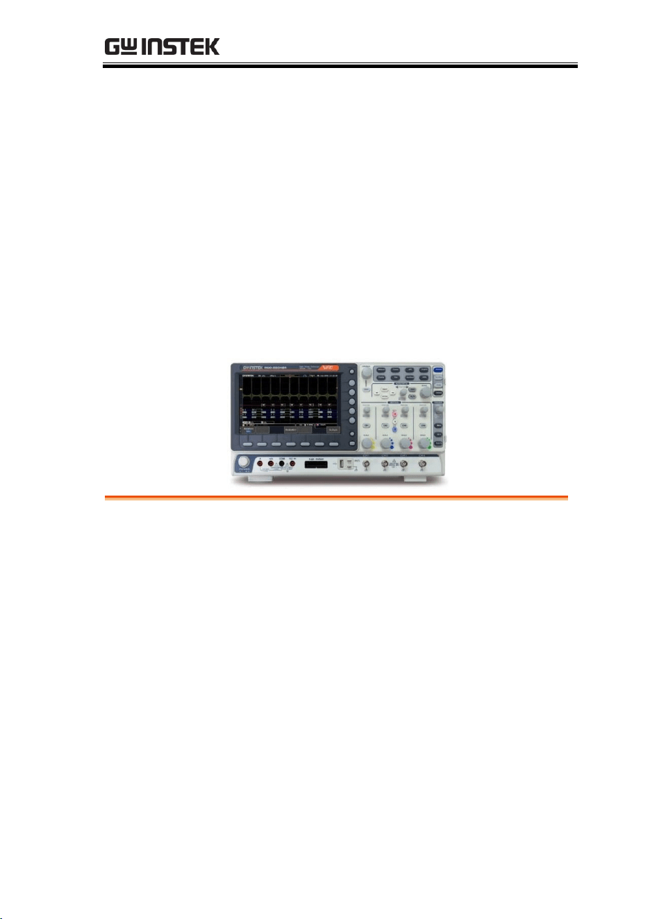
This chapter describes the MDO-2000E series in a
nutshell, including its main features and front /
rear panel. After going through the overview,
follow the Set Up section to properly set up the
device for first time use. The Set Up section also
includes an introduction on how to use this
manual effectively.
MDO-2000E Series Overview ..................................... 10
Integrated instruments and series lineup ............................................ 10
Main Features .......................................................................................... 11
Accessories .............................................................................................. 12
Appearance ................................................................ 14
MDO-2000EG/2000EX 4-channel models Front Panel ............... 14
MDO-2000EG/2000EX 2-channel models Front Panel ............... 14
MDO-2000EC/2000ES 4-channel models Front Panel ................. 15
MDO-2000EC/2000ES 2-channel models Front Panel ................. 15
MDO-2000EG/EC Rear Panel ........................................................... 23
MDO-2000EX/ES Rear Panel ............................................................ 23
Display ...................................................................................................... 25
Set Up ....................................................................... 28
Tilt Stand .................................................................................................. 28
Power Up ................................................................................................. 28
First Time Use ........................................................................................ 29
How to Use This Manual ...................................................................... 31
Built-in Help .............................................................. 37

MDO-2000E series User Manual
10
MDO-2000E Series Overview
Integrated instruments and series lineup
The MDO-2000E series have different hardware implemented
instruments:
Model name
LA
(1)
AWG
(2)
DMM
(3)
SA
(4)
Power
(5)
MDO-2000EG
✗
✓
✗
✓
✗
MDO-2000EX
✗
✓
✓
✓
✓
MDO-2000EC
✓
✓
✗
✓
✗
MDO-2000ES
✓
✓
✓
✓
✓
(1) Logic Analyzer
(2) Arbitrary Wave Generator
(3) Digital Multi-Meter
(4) Spectrum Analyzer
(5) Power Supply
The MDO-2000E series consists of 24 models, divided into 2-
channel and 4-channel versions. Note that throughout the user
manual, the term “MDO-2000E series” refers to all models of the
series, unless stated otherwise.
Model name
Frequency
bandwidth
Input
channels
Max. Real-time
Sampling Rate
MDO-2072EG /EX /EC /ES
70MHz
2
1GSa/s
MDO-2074EG /EX /EC /ES
70MHz
4
1GSa/s
MDO-2102EG /EX /EC /ES
100MHz
2
1GSa/s
MDO-2104EG /EX /EC /ES
100MHz
4
1GSa/s
MDO-2202EG /EX /EC /ES
200MHz
2
1GSa/s
MDO-2204EG /EX /EC /ES
200MHz
4
1GSa/s

GETTING STARTED
11
Main Features
Features
8 inch, 800 x 480, WVGA TFT display.
Available from 70MHz to 200MHz.
Real-time sampling rate of 1GSa/s (2 channel
models), 1GSa/s max. (4 channel models).
Deep memory: 10M points record length.
Waveform capture rate of 120,000 waveforms
per second.
Vertical sensitivity: 1mV/div~10V/div.
Segmented Memory: Optimizes the acquisition
memory to selectively capture only the
important signal details. Up to 29,000 successive
waveform segments can be captured with a
time-tag resolution of 4ns.
Waveform Search: Allows the scope to search
for a number of different signal events.
Arbitrary Wave generator: Full-function dual
channel arbitrary waveform generator.
Logic Analyzer: Can be used to measure
discrete inputs or measure values on parallel or
serial buses (for MDO-2000EC and MDO-
2000ES series only).
Spectrum Analyzer: A handy tool to perform
signal analysis in the frequency domain.
DMM: Up to 5000 count and DCV, DCA, ACV,
ACA, R, Diode, Continuity and temperature
measurement were supported (for MDO-2000EX
and MDO-2000ES series only)
Power Supply: Dual channel output, 1V to 5V
continuously adjustable (0.1V step) (for MDO-
2000EX and MDO-2000ES series only)
Powerful embedded applications such as: Data
Logging, Digital Voltmeter, Go-No Go, Mask,

MDO-2000E series User Manual
12
Digital filter, etc..
On-screen Help.
32 MB internal flash disk.
Interface
USB host port: front panel, for storage devices.
USB device port: rear panel, for remote control
or printing.
Ethernet port as standard.
Probe compensation output with selectable
output frequency (1kHz ~ 200kHz).
Calibration output.
Accessories
Standard
Accessories
Part number
Description
N/A region dependent
Power cord
GTP-70B-4, for
MDO-
2072EG/EX/EC/ES;
MDO-
2074EG/EX/EC/ES
Passive probe; 70 MHz
GTP-100B-4, for
MDO-
2102EG/EX/EC/ES;
MDO-
2104EG/EX/EC/ES
Passive probe; 100 MHz
GTP-200B-4, for
MDO-
2202EG/EX/EC/ES;
MDO-
2204EG/EX/ES/EC
Passive probe; 200 MHz
GTL-105A
Test lead for power supply
(for MDO-2000EX and MDO-
2000ES series only).
GTL-110
Test lead for AWG.

GETTING STARTED
13
GTL-207
Test lead for DMM (for MDO-
2000EX and MDO-2000ES
series only).
GTL-16E
16-channel Logic Analyzer
probe (for MDO-2000EC and
MDO-2000ES series only).
Standard Apps
Name
Description
Go-NoGo
Go-NoGo testing app.
DataLog
Waveform or image data logging
app.
DVM
Digital Voltmeter app.
Digital Filter
High ,low or band pass digital filter
for analog inputs.
Mask
Creates shape templates for signal
comparison.
Remote Disk
Allows the scope to mount a network
share drive.
Demo mode
Demonstration mode that is used
with the GDB-03 demo board.
Optional
Accessories
Part number
Description
GDB-03
Demo board.
Drivers, others
USB driver
LabVIEW driver
MDO-2000E series User Manual
14
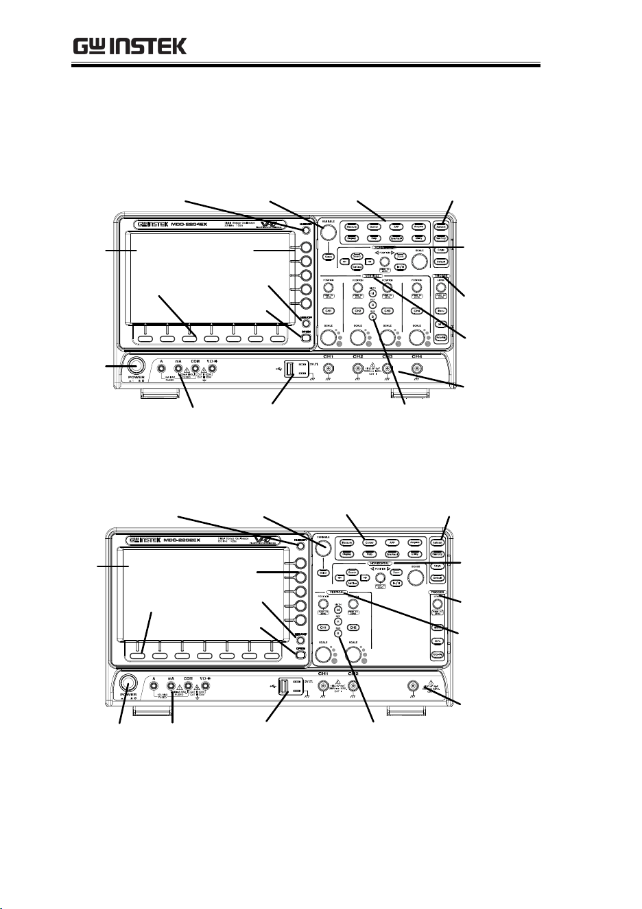
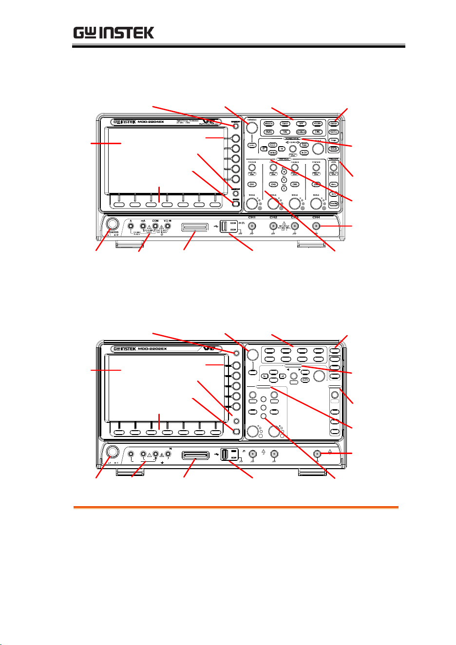
Appearance
MDO-2000EG/2000EX 4-channel models Front Panel
Side
menu keys
LCD
Variable knob
and Select key
Autoset, Run/Stop,
Single and Default
settings
Trigger
controls
Function keys
USB Host port, Probe
Compensation terminals
Power
button
Hardcopy key
Math, Reference
and Bus keys
Bottom
menu keys
Horizontal
controls
Vertical
controls
Option key
Menu key
DMM ports
CH1~CH4
MDO-2000EG/2000EX 2-channel models Front Panel
LCD
Variable knob
and Select key
Autoset, Run/Stop,
Single and Default
settings
CH1~CH2,
EXT TRIG
Trigger
controls
Function
keys
USB Host port, Probe
Compensation terminals
Hardcopy key
Math, Reference
and Bus keys
Bottom
menu keys
Vertical
controls
Option key
Menu key
Side
menu keys
DMM ports
Power
button
Horizontal
controls
EXT TRIG
GETTING STARTED
15
MDO-2000EC/2000ES 4-channel models Front Panel
Menu key
LCD
Variable knob
and Select key
Autoset, Run/Stop, Single
and Default settings
CH1~CH4
Trigger
controls
Function
keys
USB Host port, Probe
Compensation terminals
Hardcopy key
Math, Reference
and Bus keys
Vertical
controls
DMM ports
Power
button
Horizontal
controls
Logic Analyzer
probe connector
Side menu keys
Option key
Bottom menu keys
MDO-2000EC/2000ES 2-channel models Front Panel
Menu key
LCD
Variable knob
and Select key
Autoset, Run/Stop, Single
and Default settings
CH1~CH2,
EXT TRIG
Trigger
controls
Function
keys
USB Host port, Probe
Compensation terminals
Hardcopy key
Math, Reference
and Bus keys
Vertical
controls
DMM ports
Power
button
Horizontal
controls
VARIABLE
POSITION
HORIZONTAL
TRIGGER
LEVEL
PUSH TO
ZERO
PUSH TO
ZERO
SCALE
Measure
Display
Cursor
Help
APP
Save/Recall
Acquire
Utility
Autoset
Run/Stop
Single
Default
Select
Search
Set/Clear
Zoom
Menu
50 %
Force-Trig
POSITION
POSITION
VERTICAL
MATH
REF
BUS
SCALESCALE
PUSH TO
ZERO
PUSH TO
ZERO
M
R
B
Digital Storage Oscilloscope
200 MHz 1 GS/s
Visual Persistence Oscilloscope
CH1 CH2 EXT TRIG
2V
CAT I
1M
W
16pF
300Vrms MAX.
CAT I
1M
W
16pF
300Vrms MAX.
Logic Analyzer
POWER
FUSED
10A MAX
FUSED
V
W
COMA mA
CAT II600mA MAX 600V
CAT III300V
HARDCOPY
MENU OFF
OPTION
Logic Analyzer
probe connector
Side menu keys
Option key
Bottom menu keys
LCD Display
8” WVGA TFT color LCD. 800 x 480 resolution,
wide angle view display.
MDO-2000E series User Manual
16
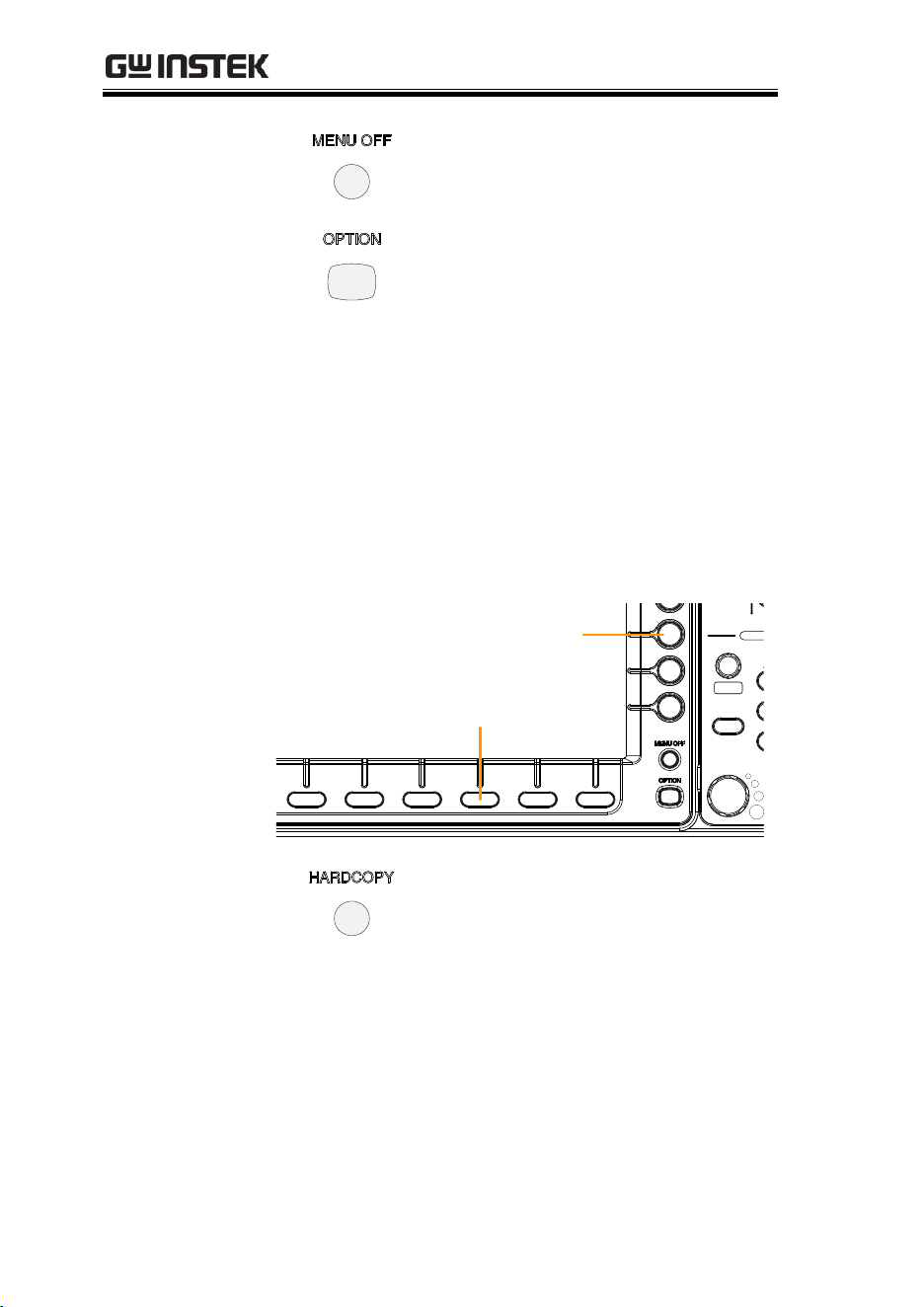
Menu Off Key
Use the Menu Off key to hide the
onscreen menu system.
Option Key
The Option key is used to access
installed options.
Menu Keys
The side menu and bottom menu keys are used to
make selections from the soft-menus on the LCD
user interface.
To choose menu items, use the 7 Bottom menu
keys located on the bottom of the display panel.
To select a variable or option from a menu, use the
side menu keys on the side of the panel. See page
31 for details.
POSITION
VER
MA
R
B
SCALE
PUSH TO
ZERO
Side menu keys
Bottom menu keys
Hardcopy Key
The Hardcopy key is a quick-save
or quick-print key, depending on
its configuration. For more
information see pages 336 (save)
or 336 (print).

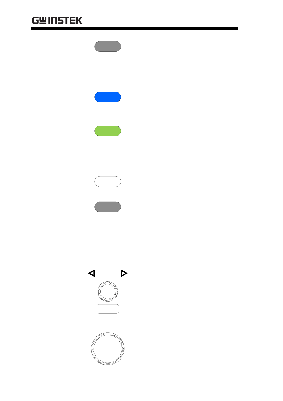
GETTING STARTED
17
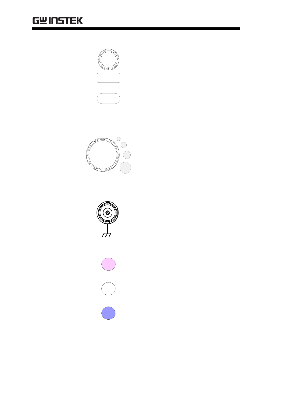
Variable Knob
and Select Key
Select
VARIABLE
The Variable knob is used to
increase/decrease values or to
move between parameters.
The Select key, when lit up, is
used to make selections.
Function Keys
The Function keys are used to enter and configure
different functions on the MDO-2000E series.
Measure
Measure
Configures and runs automatic
measurements.
Cursor
Cursor
Configures and runs cursor
measurements.
APP
APP
Configures and runs GW Instek
applications.
Acquire
Acquire
Configures the acquisition mode,
including Segmented Memory
acquisition.
Display
Display
Configures the display settings.
Help
Help
Shows the Help menu.
Save/Recall
Save/Recall
Used to save and recall
waveforms, images, panel
settings.
MDO-2000E series User Manual
18
Utility
Utility
Configures the Hardcopy key,
display time, language, probe
compensation and calibration. It
also accesses the file utilities
menu.
Autoset
Autoset
Press the Autoset key to
automatically set the trigger,
horizontal scale and vertical scale.
Run/Stop Key
Run/Stop
Press to Freeze (Stop) or continue
(Run) signal acquisition (page 42).
The run stop key is also used to
run or stop Segmented Memory
acquisition (page 88).
Single
Single
Sets the acquisition mode to
single triggering mode.
Default Setup
Default
Resets the oscilloscope to the
default settings.
Horizontal
Controls
The horizontal controls are used to change the
position of the cursor, set the time base settings,
zoom into the waveforms/traces and search for
events.
Horizontal
Position
POSITION
PUSH TO
ZERO
The Position knob is used to
position the waveforms/traces
horizontally on the display
screen. Pressing the knob will
reset the position to zero.
SCALE
SCALE
The Scale knob is used to change
the horizontal scale (TIME/DIV).
GETTING STARTED
19
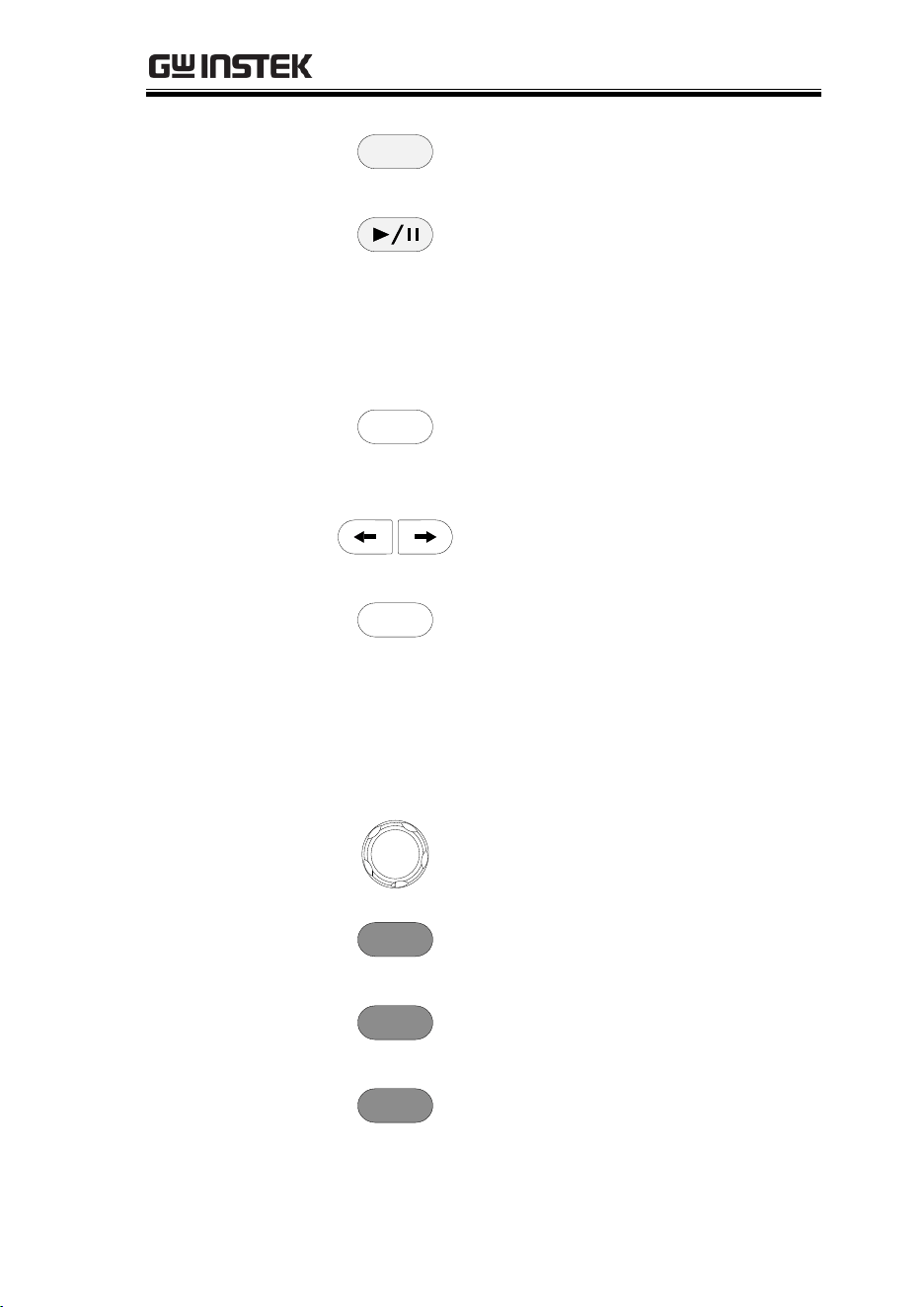
Zoom
Zoom
Press Zoom in combination with
the horizontal Position knob.
Play/Pause
The Play/Pause key allows you to
view each search event in
succession – to effectively “play”
through each search event. It is
also used to play through a
waveform/trace in zoom mode.
Search
Search
The Search key accesses the
search function menu to set the
search type, source and threshold.
Search Arrows
Use the arrow keys to navigate
the search events.
Set/Clear
Set/Clear
Use the Set/Clear key to set or
clear points of interest when
using the search function.
Trigger Controls
The trigger controls are used to control the trigger
level and options.
Level Knob
LEVEL
Used to set the trigger level.
Pressing the knob will reset the
level to zero.
Trigger Menu Key
Menu
Used to bring up the trigger
menu.
50% Key
50 %
Sets the trigger level to the half
way point (50%).
Force - Trig
Force-Trig
Press to force an immediate
trigger of the waveform.
MDO-2000E series User Manual
20
Vertical
POSITION
POSITION
PUSH TO
ZERO
Sets the vertical position of the
waveform/trace. Push the knob
to reset the vertical position to
zero.
Channel Menu
Key
CH1
Press the CH1~4 key to set and
configure the corresponding
channel.
(Vertical)SCALE
Knob
SCALE
Sets the vertical scale of the
channel (TIME/DIV).
External Trigger
Input
EXT TRIG
Accepts external trigger signals
(page 143). Only on 2 channel
models.
Input impedance: 1MΩ
Voltage input: ±15V (peak), EXT
trigger capacitance: 16pF.
Math Key
MATH
M
Use the Math key to set and
configure math functions.
Reference Key
REF
R
Press the Reference key to set or
remove reference waveforms.
BUS Key
BUS
B
The Bus key is used for serial bus
(UART, I
2
C, SPI, CAN, LIN)
configuration.
GETTING STARTED
21
Channel Inputs
CH1
Accepts input signals.
Input impedance: 1MΩ.
Capacitance: 16pF
CAT I
USB Host Port
2V
Type A, 1.1/2.0 compatible. Used
for data transfer.
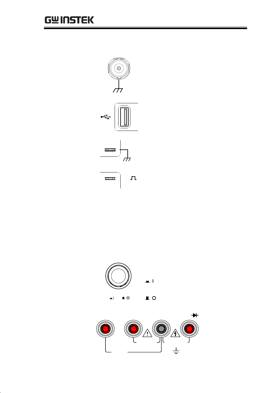
Ground Terminal
2V
Accepts the DUT ground lead for
common ground.
Probe
Compensation
Output
2V
The probe compensation output is
used for probe compensation. It
also has an adjustable output
frequency.
By default this port outputs a
2Vpp, square wave signal at 1kHz
for probe compensation.
Please see page 194 for details.
Power Switch
POWER
Used to turn the power on/off.
: ON
: OFF
DMM Ports
(For MDO-
2000EX /ES only)
10A MAX
FUSED
V
W
COMA mA
CAT II 600V
CAT III
300VFUSED
600mA MAX

MDO-2000E series User Manual
22
mA
Accepts up to 600mA.
Fuse protection: 1A.
A
Accepts up to 10A.
Fuse protection: 10A
COM
Com port
V
W
Voltage, Resistance and Diode
port.
Max voltage: 600V
Logic Analyzer
probe connector
Logic Analyzer
This probe connector is for MDO-
2000EC /ES series only.
GETTING STARTED
23
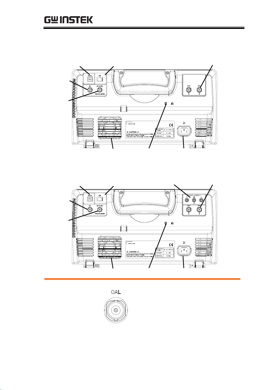
MDO-2000EG/EC Rear Panel
Calibration
output
Key lock Power input socket
Fan
Go/No Go
output
LAN portUSB Device port
AWG channels
output
MDO-2000EX/ES Rear Panel
Calibration
output
Key lock Power input socket
Fan
Go/No Go
output
LAN portUSB Device port
AWG channels
output
Power supply
output
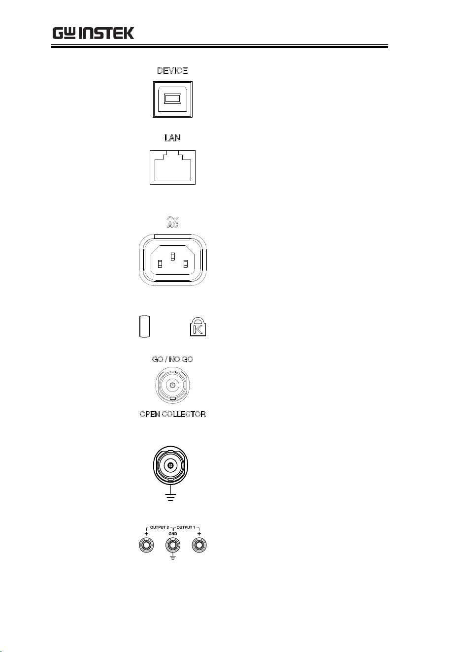
Calibration
Output
Outputs the signal for vertical scale
accuracy calibration (page 352).
MDO-2000E series User Manual
24
USB Device Port
The USB Device port is used for
remote control.
LAN (Ethernet)
Port
The LAN port is used for remote
control over a network or when
combined with the Remote Disk
app, allows the scope to be
mounted to a share disk.
Power Input
Socket
Power cord socket accepts AC
mains, 100 ~ 240V, 50/60Hz.
For power up sequence, see page
28.
Security Slot
Kensington security slot
compatible.
Go-No Go
Output
Outputs Go-No Go test results
(page 282) as a 500us pulse signal.
AWG Output
GEN 1
Output the GEN1 or GEN2 signal
from the Arbitrary Wave Generator
function. (see page 215).
Power Supply
outputs
5V/1A Dual power supply outputs,
(For MDO-2000EX /ES only, see
page 275).
GETTING STARTED
25
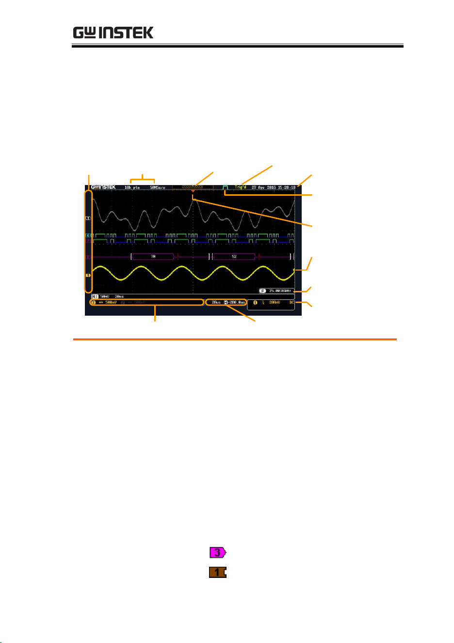
Display
Below is a general description of the main display. As the display
changes while activating the different functions of the MDO-
2000EG/2000EX, please refer to each function sub-chapters of this
user manual for more details.
Memory
bar
Reference
waveform
Analog
Waveform
Bus
decoding
Channel status Horizontal status
Trigger
configuration
Waveform
frequency
Date and time
Trigger
position
Trigger status
Acquistion
mode
Trigger level
Channel
Indicators
Memory length
and sample rate
Digital channels
Analog
Waveforms
Shows the analog input signal waveforms.
Channel 1: Yellow
Channel 2: Blue
Channel 3: Pink
Channel 4: Green
Bus decoding
Shows serial bus data decoding. The values are
displayed in hex or binary.
Reference
waveform
Reference waveform(s) can be displayed for
reference, comparison or other operations.
Digital channels
Show the digital channels. Up to 16 channels can
be displayed (Digital channel 0 to 15).
Channel
Indicators
The channel indicators for each activated channels
are located at the zero volt level of each signals.
Any active channel is shown with a solid color.
Example:
Analog channel indicator
Digital channel indicator
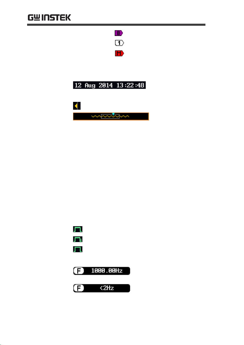
MDO-2000E series User Manual
26
Bus indicator(B)
Reference waveform indicator
Math indicator
Trigger Position
Shows the position of the trigger.
Horizontal Status
Shows the horizontal scale and position.
Date and Time
Current date and time (page 194).
Trigger Level
Shows the trigger level on the graticule.
Memory Bar
The ratio and the position of the displayed
waveform compared to the internal memory (page
102).
Trigger Status
Trig’d
Triggered.
PrTrig
Pre-trigger.
Trig?
Not triggered, display not updated.
Stop
Trigger stopped. Also appears in
Run/Stop (page 42).
Roll
Roll mode.
Auto
Auto trigger mode.
For trigger details, see page 143.
Acquisition Mode
Normal mode
Peak detect mode
Average mode
For acquisition details, see page 80.
Signal Frequency
Shows the trigger source
frequency.
Indicates the frequency is
less than 2Hz (lower
frequency limit).

MDO-2000E series User Manual
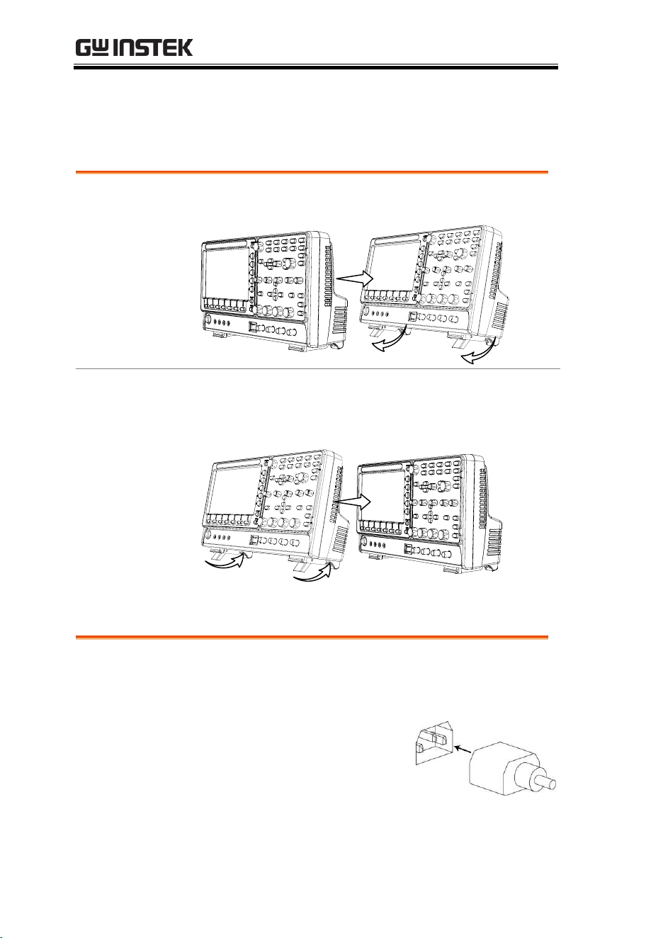
28
Set Up
Tilt Stand
Tilt
To tilt, pull the legs forward, as shown below.
Stand
To stand the scope upright, push the legs back
under the casing as shown below.
Power Up
Requirements
The MDO-2000E series accepts line voltages of 100
~ 240V at 50 or 60Hz.
Step
1. Connect the power cord to
the rear panel socket.
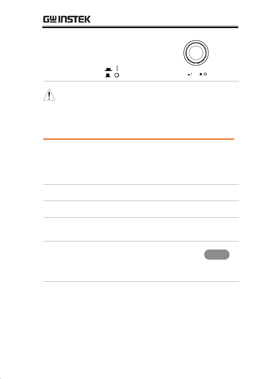
GETTING STARTED
29
2. Press the POWER key. The
display becomes active in
~ 30 seconds.
: ON
: OFF
POWER
Note
The MDO-2000E series recovers the state right before
the power is turned OFF. The default settings can be
recovered by pressing the Default key on the front
panel. For details, see page 321.
First Time Use
Background
This section describes how to connect, adjust the
scale and compensate the probe. Before operating
the MDO-2000E series in a new environment, run
these steps to make sure the instrument performs
at its full potential.
1. Power On
Follow the procedures on the previous page.
2. Firmware
Update to the latest firmware.
Page 359
3. Set the Date
and Time
Set the date and time.
Page 194.
4. Reset System
Reset the system by recalling the
factory settings. Press the Default key
on the front panel. For details, see
page 321.
Default
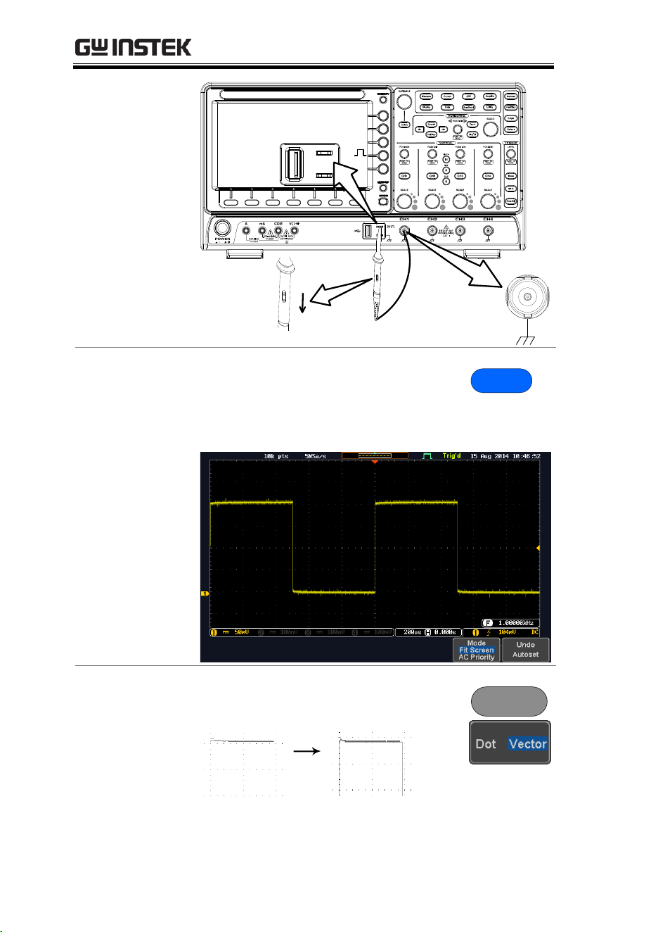
5. Connect the
probe
Connect the probe that you will use for
measurements to the Channel 1 input and to the
probe compensation output. This output provides
by default a 2V peak to peak, 1kHz square wave
for signal compensation.
Set the probe attenuation to x10 if the probe has
adjustable attenuation.
MDO-2000E series User Manual
30
x1
x10
X
10
X
1
CH1
2V
6. Capture Signal
(Autoset)
Press the Autoset key. A square
waveform appears on the center of
the screen. For Autoset details, see
page 40.
Autoset
7. Select Vector
Waveform
Press the Display key, and set the
display to Vector on the bottom menu.
Display
GETTING STARTED
31
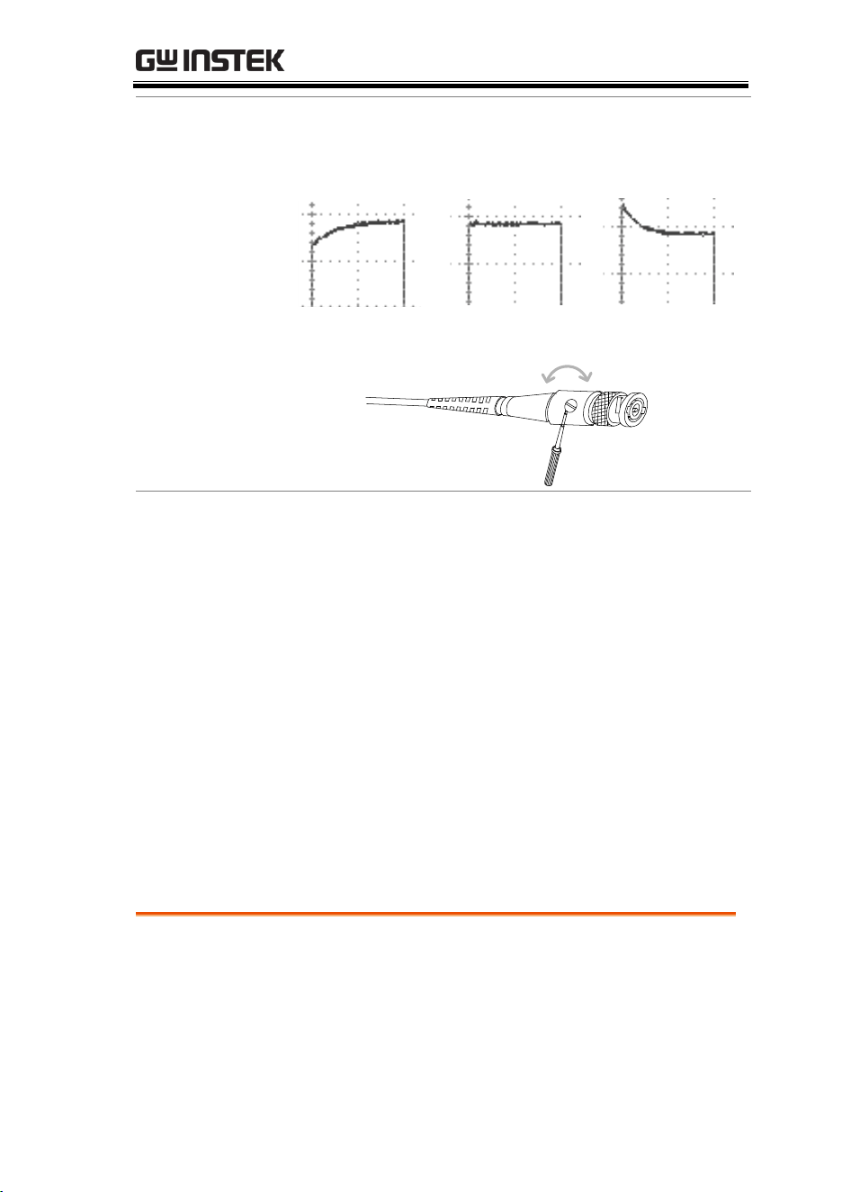
8. Compensate
the probe
Turn the adjustment point on the probe to make
the square waveform as flat as possible.
9. Start operations
Continue with the other operations.
Measurement: page 38
Configuration: page 77
Using the Logic
Analyzer: page 197
Using the Spectrum
Analyzer: page 247.
Using the Power Supply:
page 275.
Using the DMM: page
265.
Applications: page 247
Save/Recall: page 303
File Utilities: page 329
Hardcopy key: page 335
Remote Control: page
339
Maintenance: page 350
How to Use This Manual
Background
This section describes the conventions used in this
manual to operate the MDO-2000E series.
Throughout the manual any reference to pressing
a menu key refers to the keys directly below or
beside any menu icons or parameters.
Under
Compensation
Normal
Over
Compensation
MDO-2000E series User Manual
32
When the user manual says to “toggle” a value or
parameter, press the corresponding menu item.
Pressing the item will toggle the value or
parameter.
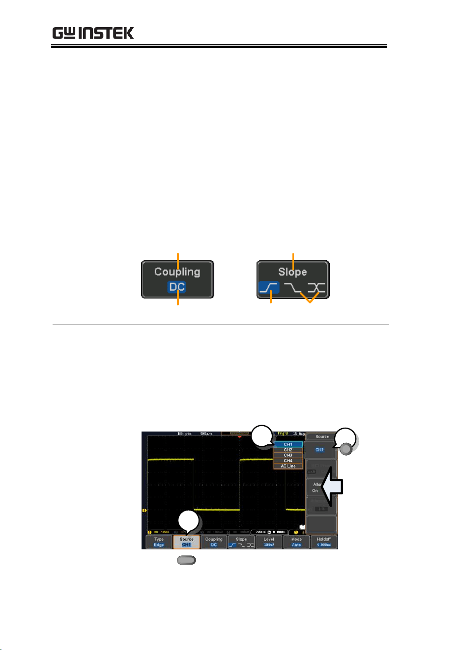
Active parameters are highlighted for each menu
item. For example in the example below, Coupling
is currently set to DC.
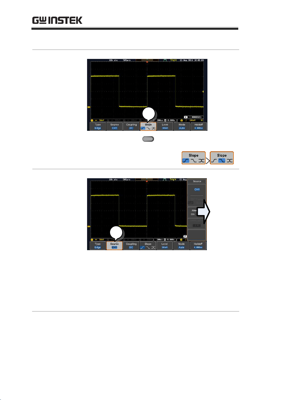
If a menu item can be toggled from one value or
parameter to another, the available options will be
visible, with the current option highlighted. In the
example below the slope can be toggled from a
rising slope to a falling slope or either slope.
Menu item
Parameter
Menu item
Active
parameter
Optional
parameters
Menu item
Selecting a Menu
Item, Parameter
or Variable
When the user manual says to “select” a value
from one of the side menu parameters, first press
the corresponding menu key and use the Variable
knob to either scroll through a parameter list or to
increase or decrease a variable.
Example 1
1
2
3
GETTING STARTED
33
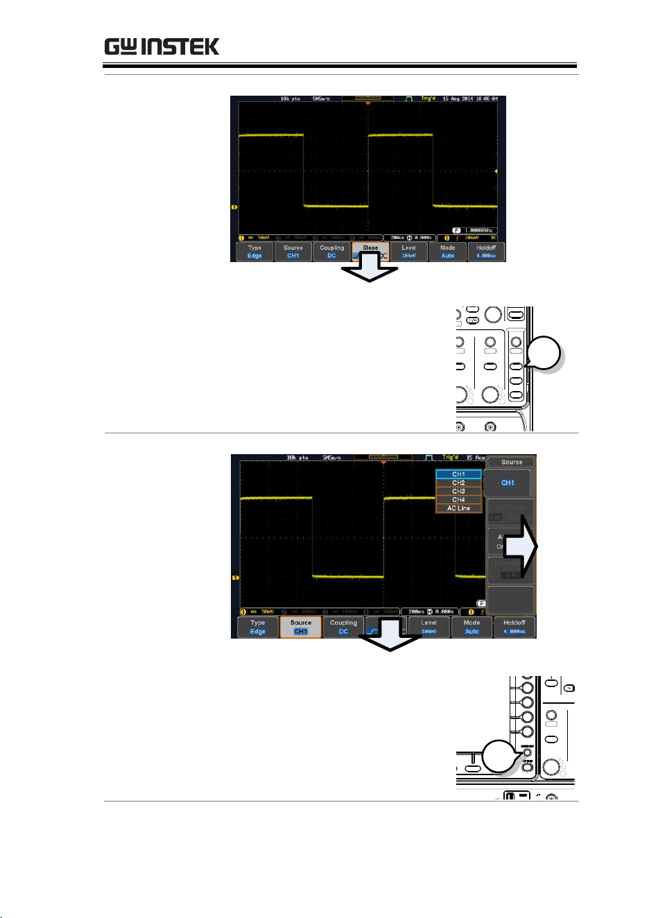
3. Press a bottom menu key to access
the side menu.
4. Press a side menu key to either set
a parameter or to access a sub
menu.
5. If accessing a sub menu or setting
a variable parameter, use the
Variable knob to scroll through
menu items or variables. Use the
Select key to confirm and exit. The
Select key is lit-up when such
selection can be made.
Select
VARIABLE
6. Press the same bottom menu key
again to reduce the side menu.
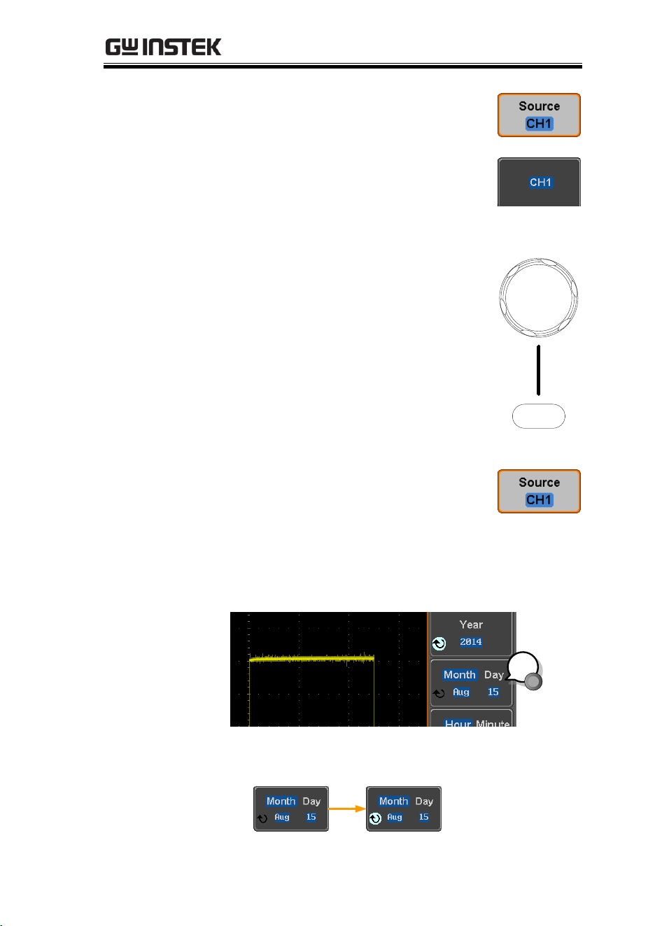
Example 2
For some variables, a circular arrow icon indicates
that the variable for that menu key can be edited
with the Variable knob.
1
7. Press the desired menu key to select it. The
circular arrow will become highlighted.
MDO-2000E series User Manual
34
8. Use the Variable knob to edit the value.
Toggling a Menu
Parameter
1
9. Press the bottom menu key
to toggle the parameter.
Reduce Side
Menu
1
10. To reduce the side menu, press the
corresponding bottom menu that brought up
the side menu.
For example: Press the Source soft-key to
reduce the Source menu.
GETTING STARTED
35
Reduce Lower
Menu
11. Press the relevant function
key again to reduce the
bottom menu. For example:
press the Trigger Menu key
to reduce the trigger menu.
VARIABLE
POSITION
HORIZONTAL
POSITION
POSITION
POSITION
POSITION
VERTICAL
MATH
REF
BUS
SCALE
TRIGGER
LEVEL
PUSH TO
ZERO
SCALESCALESCALE
PUSH TO
ZERO
PUSH TO
ZERO
PUSH TO
ZERO
PUSH TO
ZERO
PUSH TO
ZERO
SCALE
POWER
CH1 CH2 CH3 CH4
2V
CAT I
1M
W
16pF
300Vpk MAX.
Measure
Display
Cursor
Help
Test
Save/Recall
Acquire
Utility
Autoset
Run/Stop
Single
Default
Select
Search
Set/Clear
Zoom
CH1 CH2 CH3 CH4
M
R
B
Menu
50 %
Force-Trig
1
Remove All
Menus
12. Press the Menu Off key to
reduce the side menu, press
again to reduce the bottom
menu.
VARIABLE
POSITION
HORIZONTAL
POSITION
POSITION
POSITION
POSITION
VERTICAL
MATH
REF
BUS
SCALE
TRIGGER
LEVEL
PUSH TO
ZERO
SCALESCALESCALE
PUSH TO
ZERO
PUSH TO
ZERO
PUSH TO
ZERO
PUSH TO
ZERO
PUSH TO
ZERO
SCALE
POWER
CH1 CH2 CH3 CH4
2V
CAT I
1M
W
16pF
300Vpk MAX.
Measure
Display
Cursor
Help
Test
Save/Recall
Acquire
Utility
Autoset
Run/Stop
Single
Default
Select
Search
Set/Clear
Zoom
CH1 CH2 CH3 CH4
M
R
B
Menu
50 %
Force-Trig
1

MDO-2000E series User Manual
36
Remove On-
Screen Messages
13. The Menu Off key can also be
used to remove any on
screen messages.
VARIABLE
POSITION
HORIZONTAL
POSITION
POSITION
POSITION
POSITION
VERTICAL
MATH
REF
BUS
SCALE
TRIGGER
LEVEL
PUSH TO
ZERO
SCALESCALESCALE
PUSH TO
ZERO
PUSH TO
ZERO
PUSH TO
ZERO
PUSH TO
ZERO
PUSH TO
ZERO
SCALE
POWER
CH1 CH2 CH3 CH4
2V
CAT I
1M
W
16pF
300Vpk MAX.
Measure
Display
Cursor
Help
Test
Save/Recall
Acquire
Utility
Autoset
Run/Stop
Single
Default
Select
Search
Set/Clear
Zoom
CH1 CH2 CH 3 CH4
M
R
B
Menu
50 %
Force-Trig
1
GETTING STARTED
37
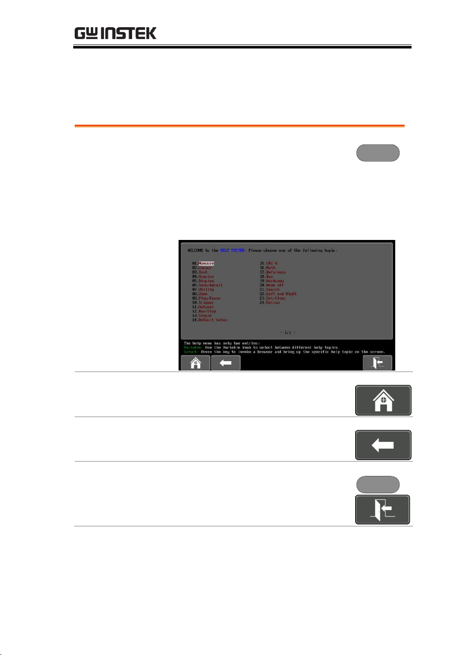
Built-in Help
The Help key accesses a context sensitive help menu. The help
menu contains information on how to use the front panel keys.
Panel Operation
1. Press the Help key. The display
changes to Help mode.
Help
2. Use the Variable knob to scroll up and down
through the Help contents. Press Select to view
the help on the selected item.
Example: Help on
the Display key
Home Key
Press the Home key to return to the
main help screen.
Go Back
Press the Back key to go to the previous
menu page.
Exit
Press the Help key again or press the
Exit key to exit the Help mode.
Help

MDO-2000E series User Manual
38
MEASUREMENT
Basic Measurement ................................................... 39
Channel Activation ................................................................................. 39
Autoset ..................................................................................................... 40
Run/Stop ................................................................................................. 42
Horizontal Position/Scale ..................................................................... 43
Vertical Position/Scale .......................................................................... 44
Automatic Measurement ............................................ 46
Measurement Items ................................................................................ 46
Add Measurement .................................................................................. 50
Remove Measurement ........................................................................... 52
Gated mode ............................................................................................. 52
Display All mode .................................................................................... 53
High Low Function ................................................................................ 54
Statistics .................................................................................................... 56
Reference Levels ..................................................................................... 58
Cursor Measurement ................................................. 60
Use Horizontal Cursors ......................................................................... 60
Use Vertical Cursors .............................................................................. 63
Math Operation ......................................................... 67
Basic Math Overview & Operators ..................................................... 67
Addition/Subtraction/Multiplication/Division................................ 67
FFT Overview & Window Functions ................................................. 69
FFT Operation ........................................................................................ 70
Advanced Math Overview .................................................................... 72
Advanced Math Operation ................................................................... 73

MEASUREMENT
39
Basic Measurement
This section describes the basic operations required in capturing,
viewing and measuring the input signal. For more detailed or more
specific operations, see the following chapters.
Advanced Configuration → from page 77
Logic Analyzer (MDO-2000EC /ES only) → from page 197
Arbitrary Wave Generator → from page 197
Spectrum Analyzer→ from page 247
Digital Multi-meter (MDO-2000EX /ES only)→ from page 265
Power Supply (MDO-2000EX /ES only)→ from page 275
Applications→ from page 279
Before operating the oscilloscope, please see the Getting Started
chapter, page 9.
Channel Activation
Activate Channel
To activate an input channel,
press a channel key.
When activated, the channel
key will light up. The
corresponding channel menu
will also appear.
CH1 CH1
Each channel is associated with the color shown
beside each channel’s vertical SCALE dial: CH1:
yellow, CH2: blue, CH3: pink and CH4: green.
When a channel is activated, it is shown above the
bottom menu system.
CH1 CH3CH2 CH4

MDO-2000E series User Manual
40
De-activate
Channel
To de-activate a channel, press
the corresponding channel key
again. If the channel menu is
not open, press the channel key
twice (the first press shows the
Channel menu).
CH1 CH1
Default Setup
To activate the default state,
press Default (this will reset the
system and recall the factory
defaults, see page 321).
Default
Autoset
Background
The Autoset function automatically configures the
panel settings to position the input signal(s) to the
best viewing condition. The MDO-2000E Series
automatically configures the following parameters:
Horizontal scale
Vertical scale
Trigger source channel
There are two operating modes for the Autoset
function: Fit Screen Mode and AC Priority Mode.
Fit Screen Mode will fit the waveform to the best
scale, including any DC components (offset). AC
priority mode will scale the waveform to the
screen by removing any DC component.
Panel Operation
1. Connect the input signal to the
MDO-2000E series and press the
Autoset key.
Autoset
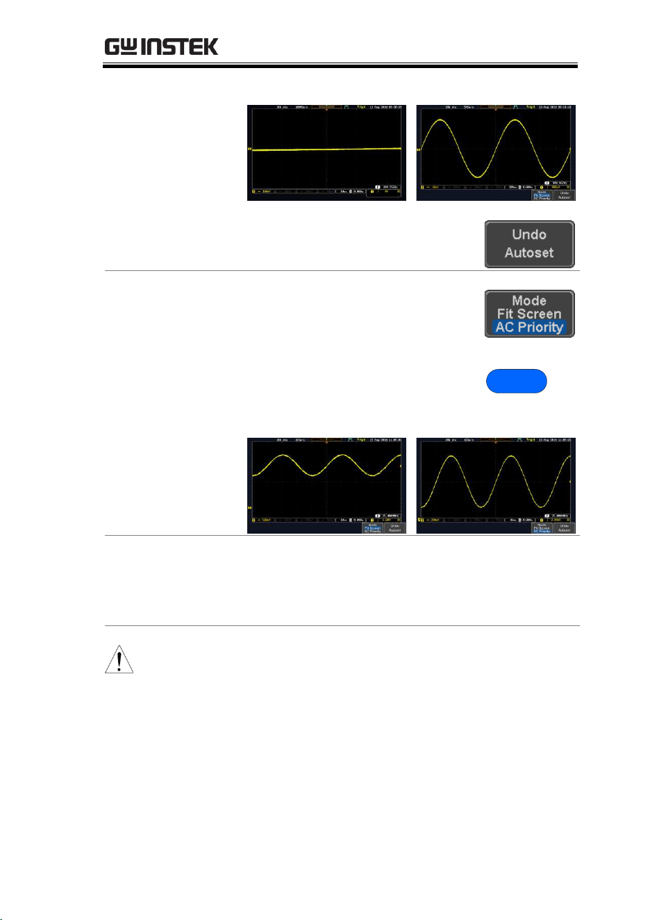
2. The waveform appears in the center of the
display.
MEASUREMENT
41
Before
After
3. To undo Autoset, press Undo
Autoset from the bottom menu.
Change modes
4. Choose between Fit Screen Mode
and AC Priority Mode from the
bottom menu.
5. Press the Autoset key again to use
Autoset in the new mode.
Autoset
Fit Screen Mode
AC Priority
Limitation
Autoset does not work in the following situations:
Input signal frequency is less than 20Hz
Input signal amplitude is less than 10mV
Note
The Autoset key does NOT automatically activate the
channels to which input signals are connected.
MDO-2000E series User Manual
42
Run/Stop
Background
By default, the waveform on the display is
constantly updated (Run mode). Freezing the
waveform by stopping signal acquisition (Stop
mode) allows flexible observation and analysis. To
enter Stop mode, two methods are available:
pressing the Run/Stop key or using the Single
Trigger mode.
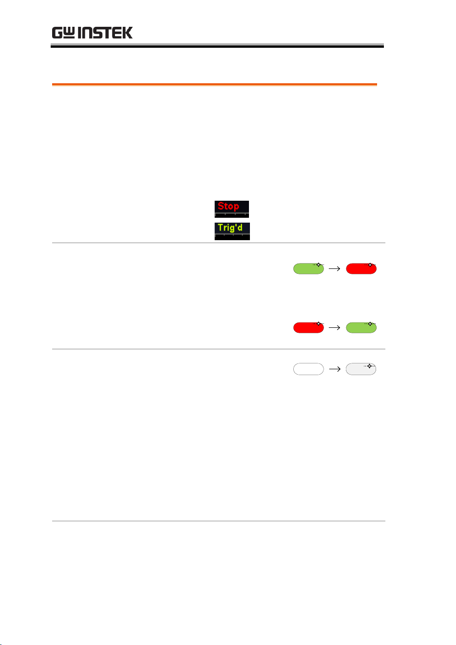
Stop mode icon
When in Stop mode, the
Stop icon appears at the
top of the display.
Triggered icon
Freeze Waveform
using the
Run/Stop Key
Press the Run/Stop key once.
The Run/Stop key turns red.
The waveform and signal
acquisition freezes.
Stop:
Run/Stop Run/Stop
To unfreeze, press the Run/Stop
key again. The Run/Stop key
turns green again.
Run:
Run/Stop Run/Stop
Freeze Waveform
by Single Trigger
Mode
Press the Single key to go into
the Single Trigger mode. The
Single key turns bright white.
In the Single Trigger mode, the
scope will be put into the pre-
trigger mode until the scope
encounters the next trigger
point. After the scope has
triggered, it will remain in Stop
mode, until the Single key is
pressed again or the Run/Stop
key is pressed.
SingleSingle
Waveform
Operation
The waveform can be moved or scaled in both Run
and Stop mode, but in different manners. For
details, see page 102 (Horizontal position/scale)
and page 110 (Vertical position/scale).
MEASUREMENT
43
Horizontal Position/Scale
For more detailed configuration, see page 102.
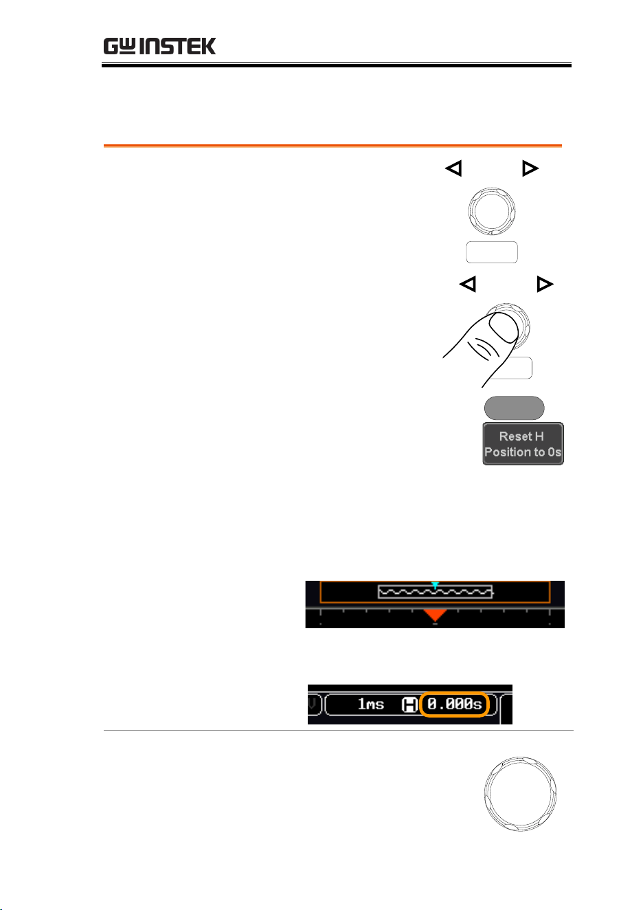
Set Horizontal
Position
The horizontal position knob
moves the waveform left and
right.
POSITION
PUSH TO
ZERO
Set Horizontal
Position to 0
Pressing the horizontal position
knob will reset the horizontal
position to 0.
POSITION
PUSH TO
ZERO
Alternatively, pressing the Acquire
key and then pressing Reset H
Position to 0s from the bottom menu
will also reset the horizontal position.
Acquire
As the waveform moves, the display bar on the top
of the display indicates the portion of the
waveform currently shown on the display and the
position of the horizontal marker on the
waveform.
Position Indicator
The horizontal position is shown at the bottom of
the display grid to the right of the H icon.
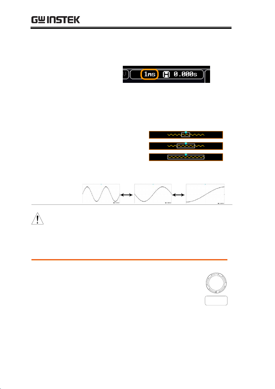
Select Horizontal
Scale
To select the timebase, turn the
horizontal SCALE knob; left (slow) or
right (fast).
SCALE
MDO-2000E series User Manual
44
Range
1ns/div ~ 100s/div, 1-2-5 increments
The scale is displayed to the left of the H icon at
the bottom of the screen.
Display bar
The display bar indicates how much
of the waveform is displayed on the
screen at any given time. Changes to
timebase will be reflected on the
display bar.
Fast
Medium
Slow
Stop mode
In the Stop mode, the waveform size
changes according to the scale.
Note
The Sample rate changes according to the timebase
and record length. See page 83.
Vertical Position/Scale
For more detailed configuration, see page 110.
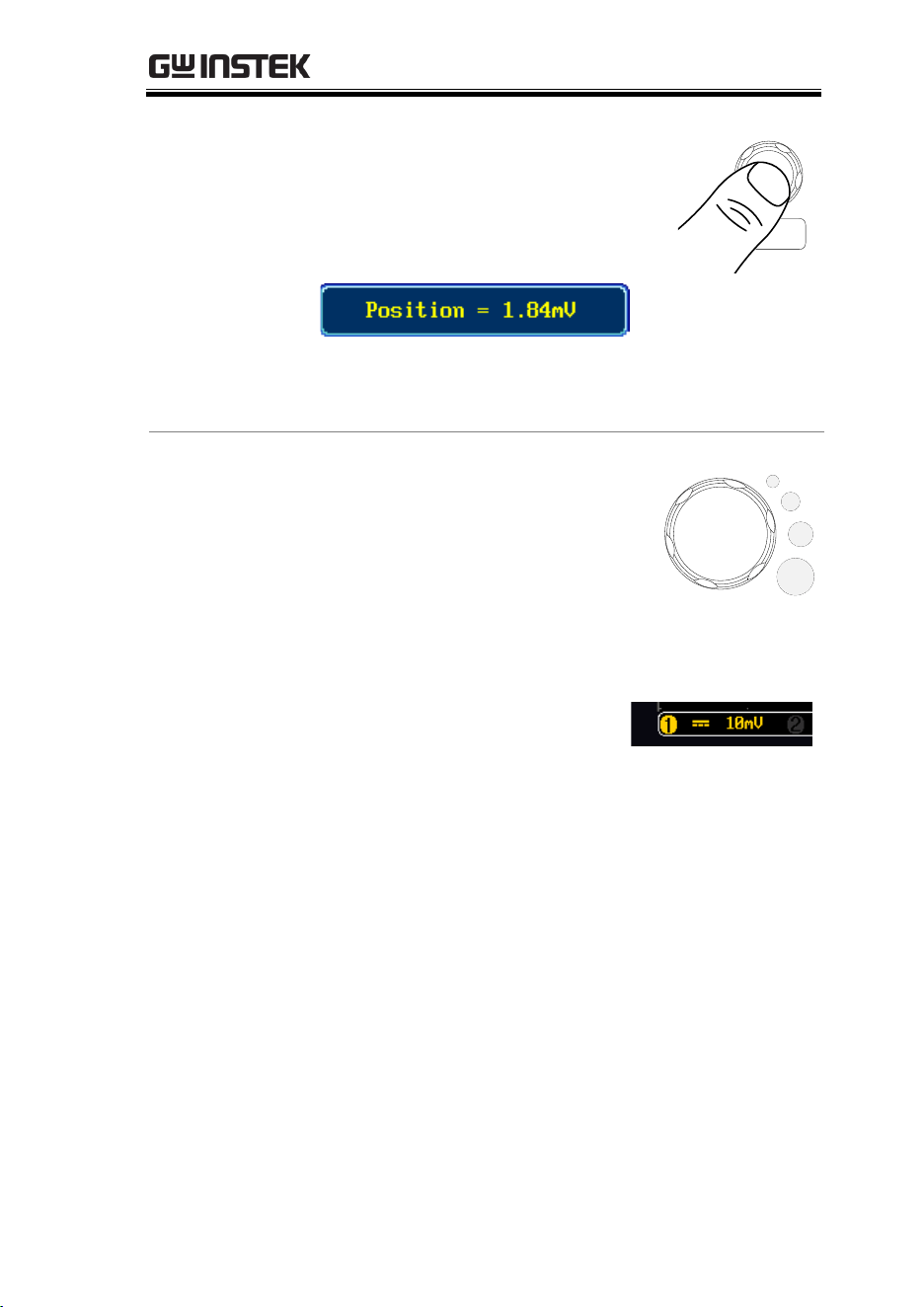
Set Vertical
Position
To move the waveform up or down, turn
the vertical position knob for each channel.
POSITION
PUSH TO
ZERO
MEASUREMENT
45
Push the vertical position knob to
reset the position to 0.
As the waveform moves, the
vertical position of the channel
indicator appears on the display.
POSITION
PUSH TO
ZERO
Run/Stop
mode
The waveform can be moved
vertically in both Run and Stop
mode.
Select Vertical
Scale
To change the vertical scale, turn
the vertical SCALE knob; left
(down) or right (up).
SCALE
Range
1mV/div ~ 10V/div
1-2-5 increments
The vertical scale indicator for
each channel on the bottom of
the display changes
accordingly.
MDO-2000E series User Manual
46
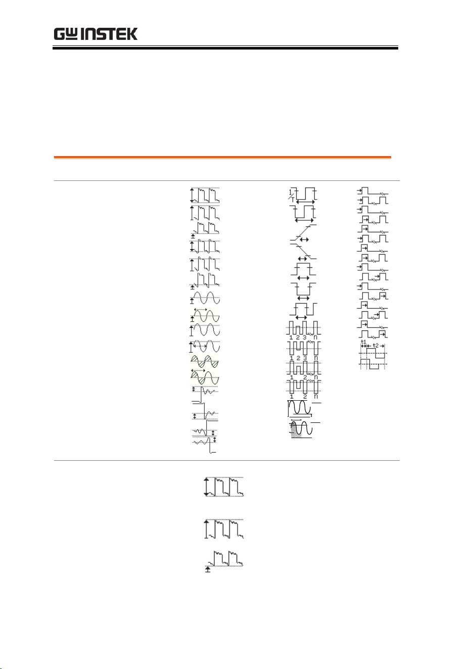
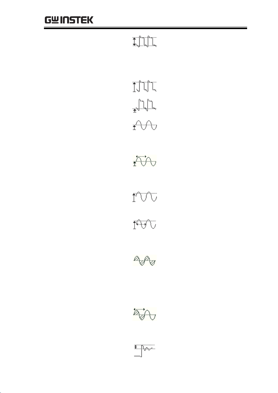
Automatic Measurement
The automatic measurement function measures and updates major
items for Voltage/Current, Time, and Delay type measurements.
Measurement Items
V/I Measurements
Time Meas.
Delay Meas.
Overview
FPREShoot
RPREShoot
FOVShoot
ROVShoot
Cycle Area
Area
Cycle RMS
RMS
Cycle Mean
Mean
Low
High
Amplitude
Min
Max
Pk-Pk
Frequency
Dutycycle
-Width
+Width
FallTime
RiseTime
Period
-Edges
+Edges
-Pulses
+Pulses
% Flicker
Flicker Idx
A
B
(A-B)
(A+B)
A1
A1
A1+A2
A2
Voltage/Current
Measurement
Pk-Pk
(peak to
peak)
Difference between positive
and negative peak.
(=max − min)
Max
Positive peak.
Min
Negative peak.
FRR
FRF
FFR
Phase
LFF
LFR
LRF
LRR
FFF
MEASUREMENT
47
Amplitude
Difference between the
global high value and the
global low value, measured
over the entire waveform or
gated region. (=high − low)
High
Global high voltage. See
page 54 for details.
Low
Global low voltage. See page
54 for details.
Mean
The arithmetic mean value is
calculated for all data
samples as specified by the
Gating option.
Cycle Mean
The arithmetic mean value is
calculated for all data
samples within the first cycle
found in the gated region.
RMS
The root mean square of all
data samples specified by the
Gating option.
Cycle RMS
The root mean square value
is calculated for all data
samples within the first cycle
found in the gated region.
Area
Measures the positive area of
the waveform and subtracts
it from the negative area. The
ground level determines the
division between positive
and negative areas.
Cycle Area
The Summation based on all
data samples within the first
cycle found in the gated
region.
ROVShoot
Rise overshoot
MDO-2000E series User Manual
48
FOVShoot
Fall overshoot
RPREShoot
Rise preshoot
FPREShoot
Fall preshoot
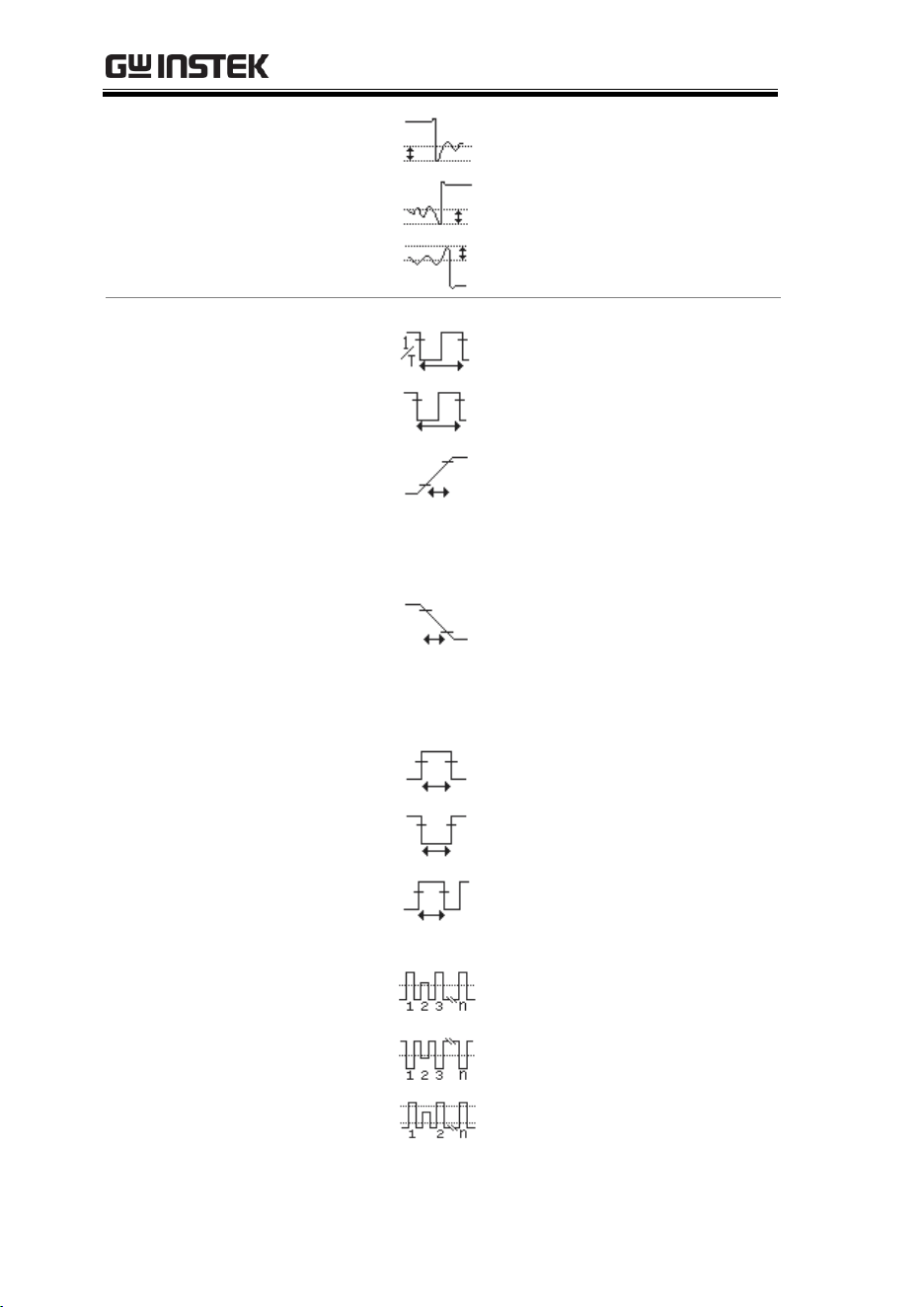
Time
Measurement
Frequency
Frequency of the waveform.
Period
Waveform cycle time.
(=1/Freq)
RiseTime
The time required for the
leading edge of the first
pulse to rise from the low
reference value to the high
reference value.
FallTime
The time required for the
falling edge of the first pulse
to fall from the high
reference value to the low
reference value.
+Width
Positive pulse width.
–Width
Negative pulse width.
Duty Cycle
Ratio of signal pulse
compared with whole cycle.
=100x (Pulse Width/Cycle)
+Pulses
Measures the number of
positive pulses.
-Pulses
Measures the number of
negative pulses.
+Edges
Measures the number of
positive edges.
MEASUREMENT
49
-Edges
Measures the number of
negative edges.
% Flicker
A
B
(A-B)
(A+B)
Ratio in percentage of the
peak-to-peak value to the
sum of peak values.
Flicker Idx
A1
A1
A1+A2
A2
Ratio of the area above the
average to the total area
during one cycle.
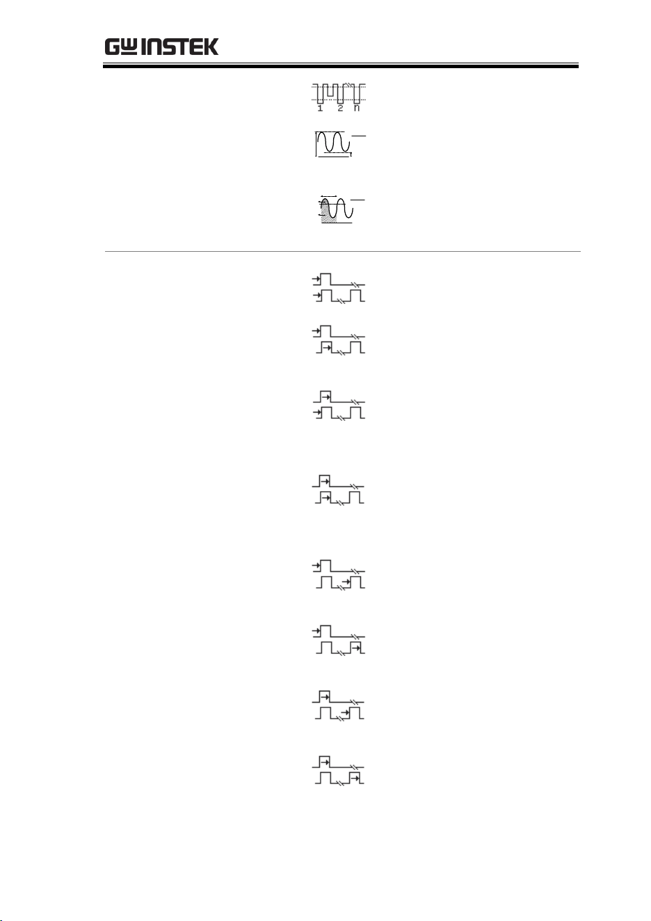
Delay
Measurement
FRR
Time between:
Source 1 first rising edge and
Source 2 first rising edge.
FRF
Time between:
Source 1 first rising edge and
Source 2 first falling edge.
FFR
Time between:
Source 1 first falling edge
and Source 2 first rising
edge.
FFF
Time between:
Source 1 first falling edge
and Source 2 first falling
edge.
LRR
Time between:
Source 1 first rising edge and
Source 2 last rising edge.
LFR
Time between:
Source 1 first rising edge and
Source 2 last falling edge.
LRF
Time between:
Source 1 first falling edge
and Source 2 last rising edge.
LFF
Time between:
Source 1 first falling edge
and Source 2 last falling
edge.
MDO-2000E series User Manual
50
Phase
The phase difference of two
signals, calculated in
degrees.
360x
t2
t1
Note
The in-built help system can be used to see detailed
automatic measurement definitions.
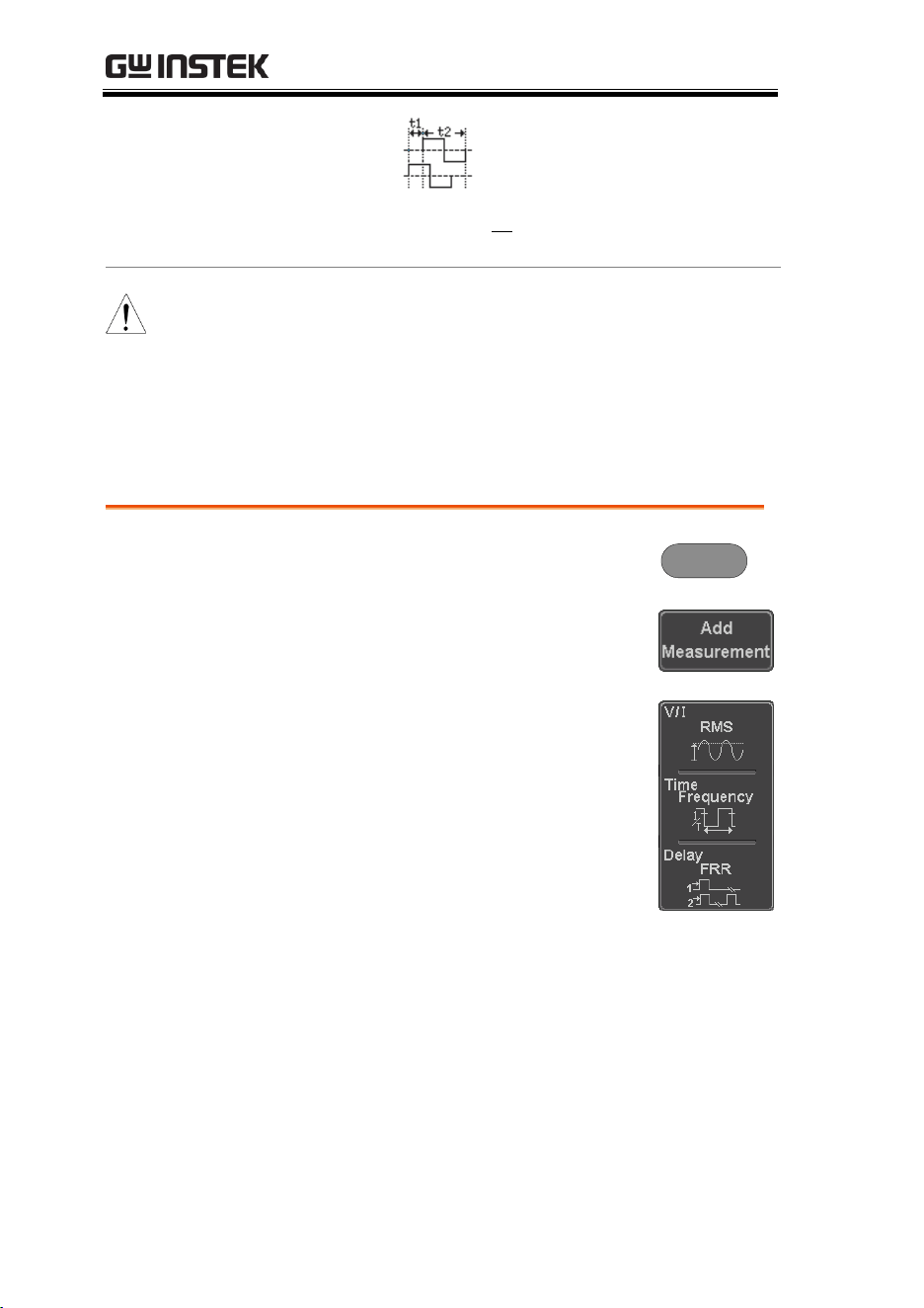
Add Measurement
The Add Measurement function allows you to add up to eight
automatic measurement items on the bottom of the screen from any
channel source.
Add
Measurement
Item
1. Press the Measure key.
Measure
2. Press Add Measurement from the
bottom menu.
3. Choose either a V/I, Time or Delay
measurement from the side menu
and choose the type of
measurement you wish to add.
V/I
(Voltage/
Current)
Pk-Pk, Max, Min, Amplitude, High,
Low, Mean, Cycle Mean, RMS,
Cycle RMS, Area, Cycle Area,
ROVShoot, FOVShoot, RPREShoot,
FPREShoot
Time
Frequency, Period, RiseTime,
FallTime, +Width, –Width, Duty
Cycle, +Pulses, -Pulses, +Edges, -
Edges, %Flicker, FlickerIndex
MEASUREMENT
51
Delay
FRR, FRF, FFR, FFF, LRR, LRF, LFR,
LFF, Phase
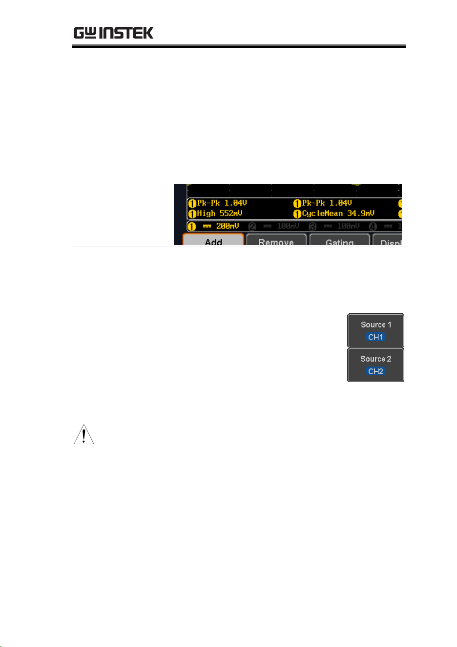
4. All of the chosen automatic measurements will
be displayed in a window on the bottom of the
screen. The channel number and channel color
indicate the measurement source.
For the analog inputs: yellow = CH1,
blue = CH2, pink = CH3, green = CH4.
Choose a Source
The channel source for measurement items can be
set either before or when selecting a measurement
item.
5. To set the source, press either the
Source1 or Source2 key from the
side menu and choose the source.
Range
Source1: CH1~CH4, Math, D0~D15
Source2: CH1~CH4, Math
(Note)
Source 2 is only applicable to Delay
measurements.
Only selected Time Frequency measurements
can be applied to Digital channels D0~D15:
Frequency, Period, +Width, -Width and
Dutycycle.
MDO-2000E series User Manual
52
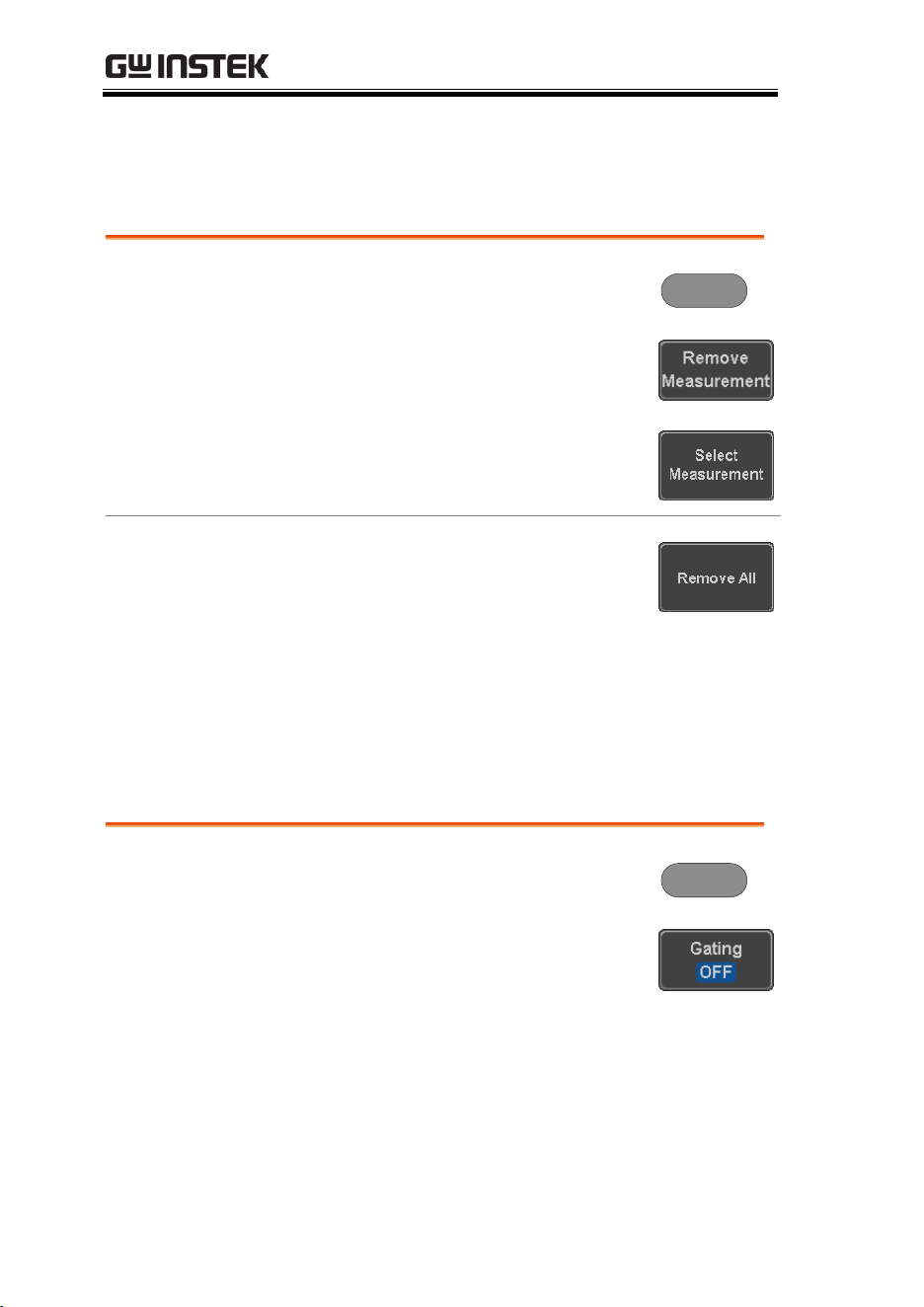
Remove Measurement
Individual measurements can be removed at any time using the
Remove Measurement function.
Remove
Measurement
Item
1. Press the Measure key.
Measure
2. Press Remove Measurement from the
bottom menu.
3. Press Select Measurement and select
the item that you want to remove
from the measurement list.
Remove All Items
Press Remove All to remove all the
measurement items.
Gated mode
Some automatic measurements can be limited to a “gated” area
between cursors. Gating is useful for measuring a magnified
waveform or when using a fast time base. The Gated mode has
three possible configurations: Off (Full Record), Screen and
Between Cursors.
Set Gating Mode
1. Press the Measure key.
Measure
2. Press Gating from the bottom
menu.
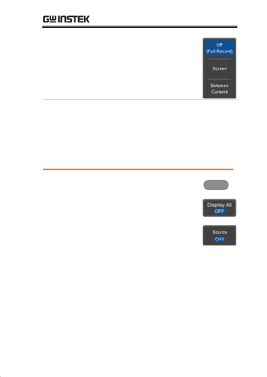
MEASUREMENT
53
3. Choose one of the gating modes
from the side menu: Off (full
record), Screen, Between Cursors.
Cursors On
Screen
If Between Cursors is selected, the
cursor positions can be edited by
using the cursor menu.
Page 60
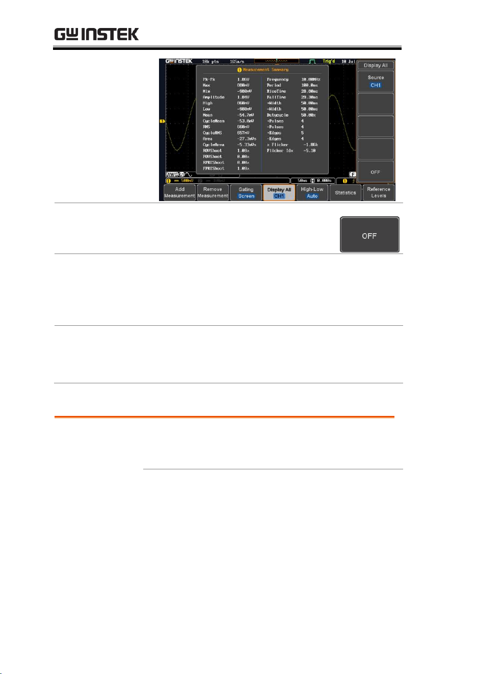
Display All mode
Display All mode shows and updates all items from Voltage and
Time type measurements.
View
Measurement
Results
1. Press the Measure key.
Measure
2. Press Display All from the bottom
menu.
3. Press Source from the side menu
and choose a measurement source.
Range
CH1~CH4, Math, D0~D15
4. The results of Voltage and Time type
measurements appear on the display.
MDO-2000E series User Manual
54
Remove
Measurements
To remove the measurement results,
press OFF.
Delay
Measurements
Delay type measurements are not available in this
mode as only one channel is used as the source.
Use the individual measurement mode (page 50)
instead.
Digital channels
Only Frequency, Period, +Width, -Width and Duty
Cycle measurements are supported for the digital
channels D0~D15
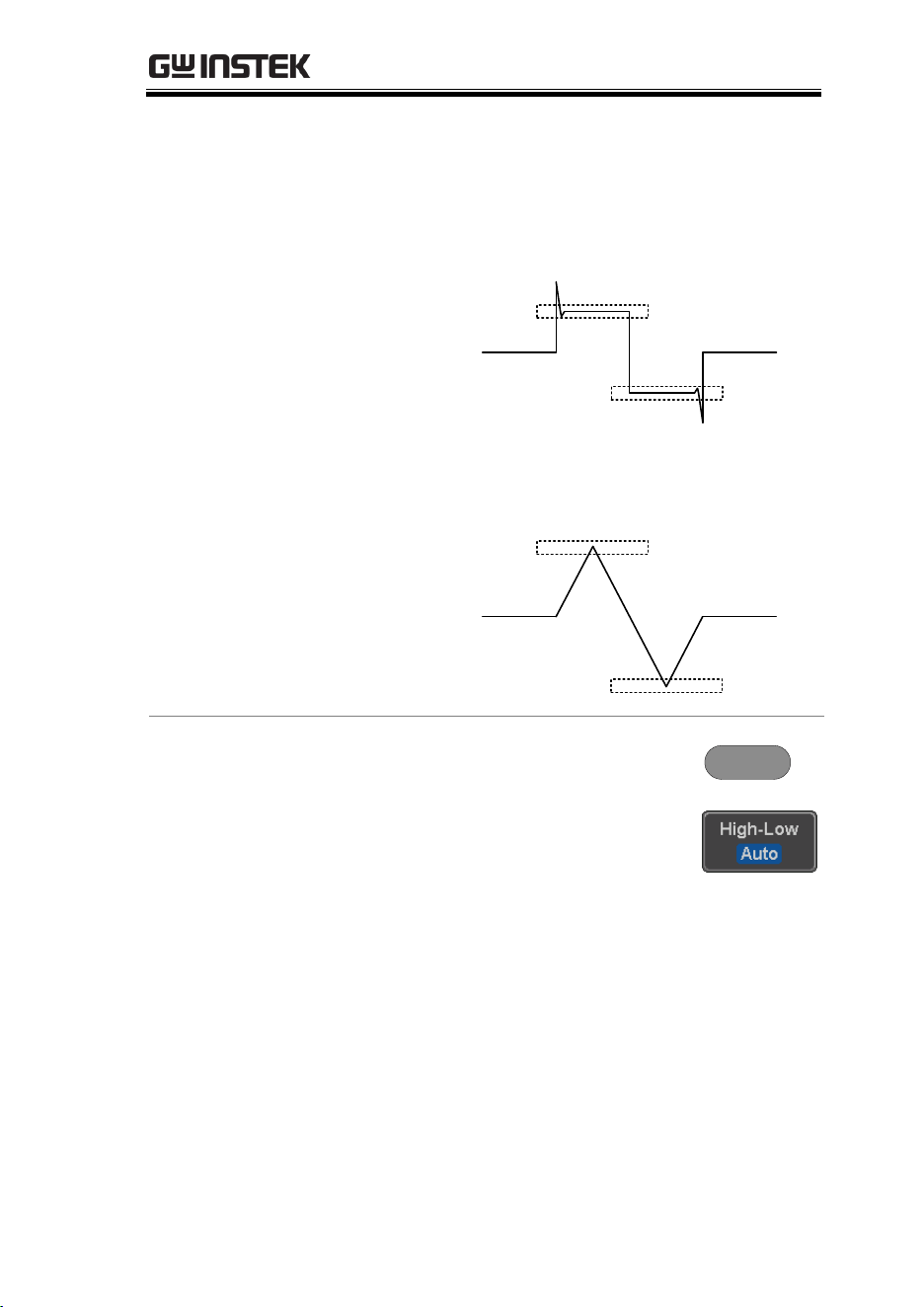
High Low Function
Background
The High-Low function is used to select the
method for determining the value of the High-Low
measurement values.
Auto
Automatically chooses the best
high-low setting for each
waveform when measuring.
MEASUREMENT
55
Histogram
Uses histograms to determine the
high-low values. This mode
ignores any pre-shoot or
overshoot values. This mode is
particularly useful for pulse-type
waveforms
low
high
Min-max
Sets the high-low values as the
minimum or maximum measured
values.
low
high
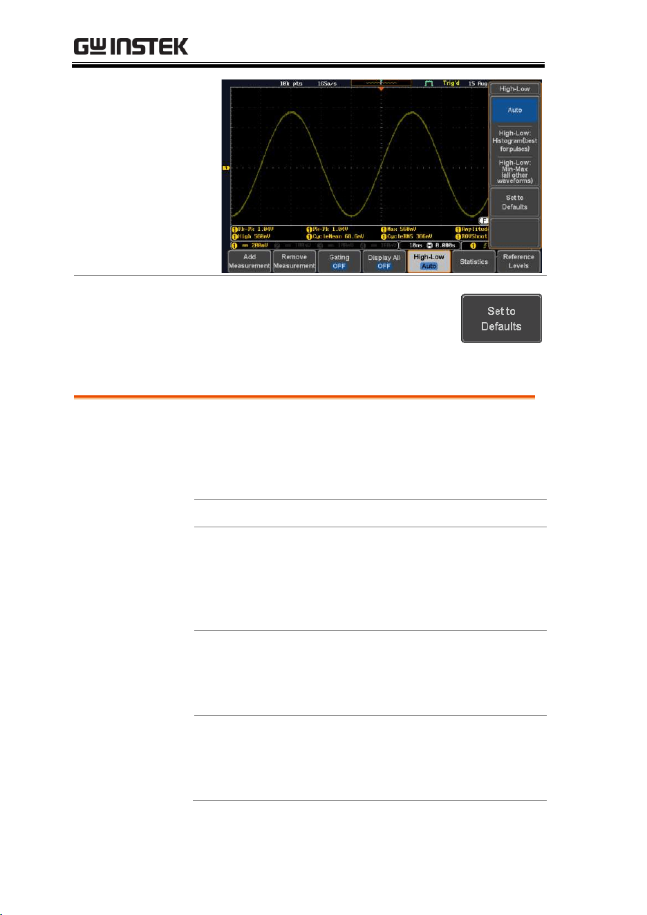
Set High-Low
1. Press the Measure key.
Measure
2. Press High-Low from the bottom
menu.
3. Select the type of High-Low settings from the
side menu.
High-Low Settings:
Histogram, Min-Max,
Auto
MDO-2000E series User Manual
56
Restore Default
High-Low
Settings
To return to the default High-Low
settings, press Set to Defaults.
Statistics
Background
The Statistics function can be used to view a
number of statistics for the selected automatic
measurements. The following information is
displayed with the Statistics function:
Value
Currently measured value
Mean
The mean value is calculated from
a number of automatic
measurement results. The number
of samples used to determine the
mean can be user-defined.
Min
The minimum value observed
from a series of measured results
for the selected automatic
measurement items.
Max
The maximum value observed
from a series of measured results
for the selected automatic
measurement items.
MEASUREMENT
57
Standard
Deviation
The variance of the currently
measured value from the mean.
The standard deviation equals the
squared root of the variance value.
Measuring the standard deviation
can, for example, determine the
severity of jitter in a signal.
The number of samples used to
determine the standard deviation
can be user-defined.
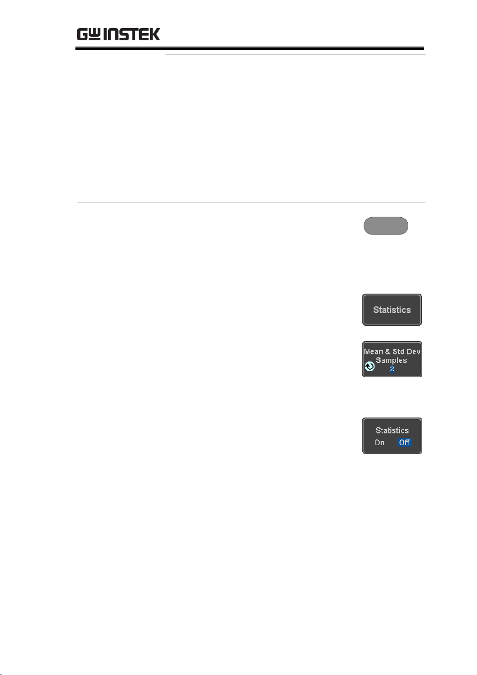
Panel Operation
1. Press the Measure key.
Measure
2. Select at least one automatic
measurement.
Page 50
3. Press Statistics from the bottom
menu.
4. Set the number of samples to be
used in the mean and standard
deviation calculations.
Samples:
2~1000
5. Press Statistics and turn Statistics
on.
6. The statistics for each automatic measurement
will appear at the bottom of the display in a
table.
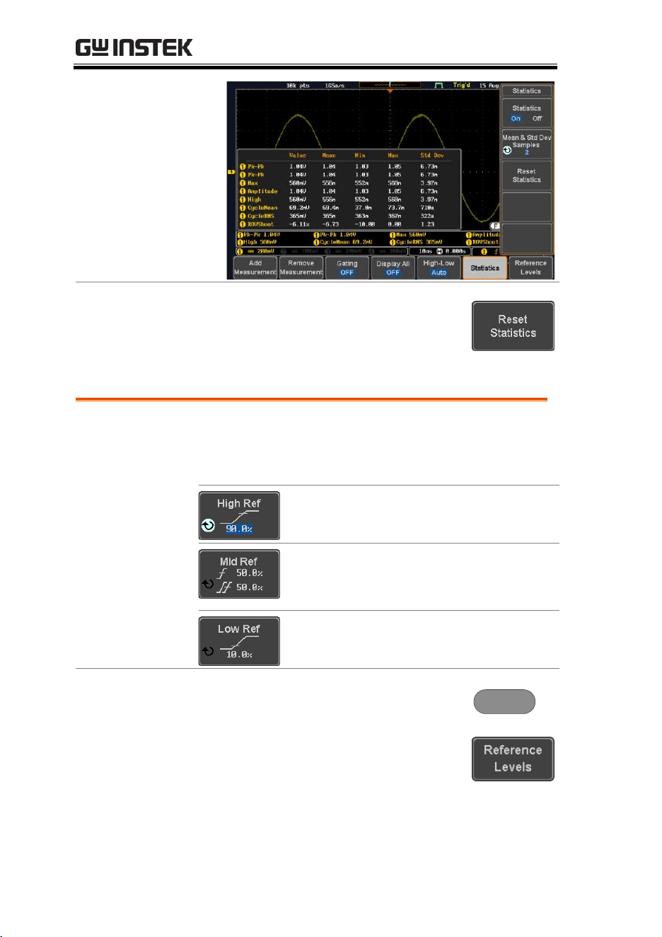
MDO-2000E series User Manual
58
Reset Statistics
To reset the standard deviation
calculations, press Reset Statistics.
Reference Levels
Background
The reference level settings determine the
measurement threshold levels for some
measurements like the Rise Time measurement.
High Ref: Sets the high reference
level.
Mid Ref: Sets the middle reference
for the first and second
waveforms.
Low Ref: Sets the low reference
level.
Panel Operation
1. Press the Measure key.
Measure
2. Press Reference Levels from the
bottom menu.

MEASUREMENT
59
3. Set the reference levels from the side menu.
Ensure the reference levels do not cross over.
High Ref
0.0% ~ 100%
Mid Ref
0.0% ~ 100%
0.0% ~ 100%
Low Ref
0.0% ~ 100%
Default Settings
4. Press Set to Defaults to set the
reference levels back to the default
settings.
MDO-2000E series User Manual
60
Cursor Measurement
Horizontal or vertical cursors are used to show the position and
values of waveform measurements and math operation results.
These results cover voltage, time, frequency and other math
operations. When the cursors (horizontal, vertical or both) are
activated, they will be shown on the main display unless turned off.
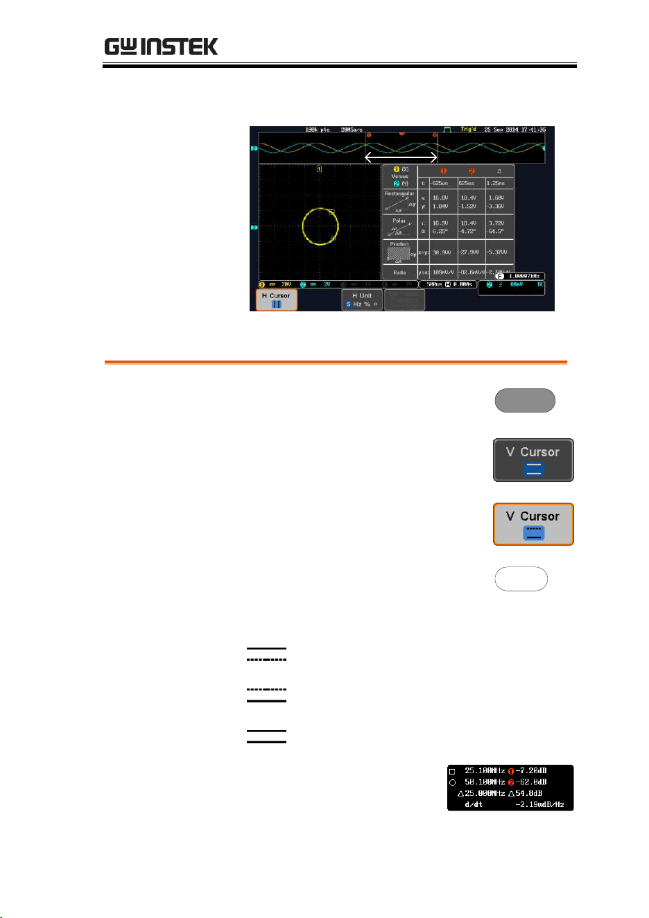
Use Horizontal Cursors
Panel Operation
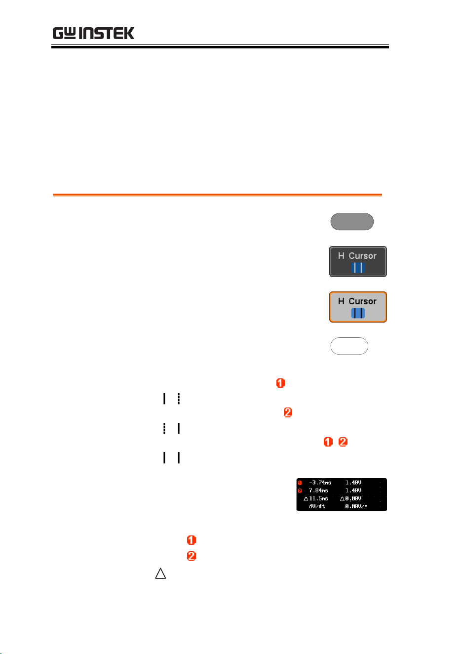
1. Press the Cursor key once.
Cursor
2. Press H Cursor from the bottom
menu if it is not already selected.
3. When the H Cursor is selected,
repeatedly pressing the H Cursor
key or the Select key will toggle
which cursor is selected.
OR
Select
Range
Description
Left cursor ( ) movable, right
cursor position fixed
Right cursor ( ) movable, left
cursor position fixed
Left and right cursor ( + )
movable together
4. The cursor position
information appears on the
top left hand side of the
screen
Cursor
Hor. position, Voltage/Current
Cursor
Hor. position, Voltage/Current
Delta (difference between cursors)
dV/dt or dI/dt
MEASUREMENT
61
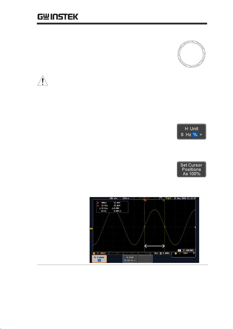
5. Use the Variable knob to move the
movable cursor(s) left or right.
VARIABLE
(Note)
The selected cursor(s) will move
along the active waveform. To
move along another waveform,
select its corresponding channel
and press the cursor key again to
re-enter the cursor menu.
Select Units
6. To change the units of the
horizontal position, press H Unit.
Units
S, Hz, % (ratio), ˚(phase)
Phase or Ratio
Reference
7. To set the 0% and 100% ratio or the
0˚ and 360˚ phase references for the
current cursor positions, press Set
Cursor Positions As 100%.
Example
Horizontal
cursors
MDO-2000E series User Manual
62
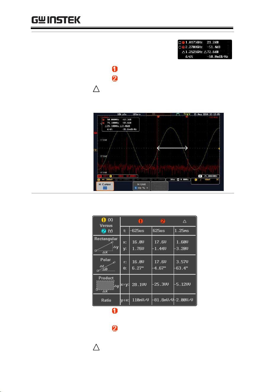
FFT
FFT cursors can use different
units. For FFT details, see page
69.
Cursor
Hor. position, dB/Voltage
Cursor
Hor. Position, dB/Voltage
Delta (difference between cursors)
dV/dt or d/dt
Example
Horizontal
cursors
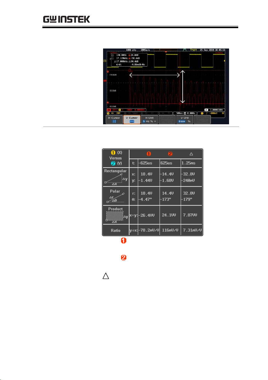
XY Mode
XY mode cursors measure a number of X by Y
measurements. See page 81.
Cursor
Time, rectangular, polar co-
ordinates, product, ratio.
Cursor
Time, rectangular, polar co-
ordinates, product, ratio.
Delta (difference between cursors)
MEASUREMENT
63
Example
Horizontal
cursors
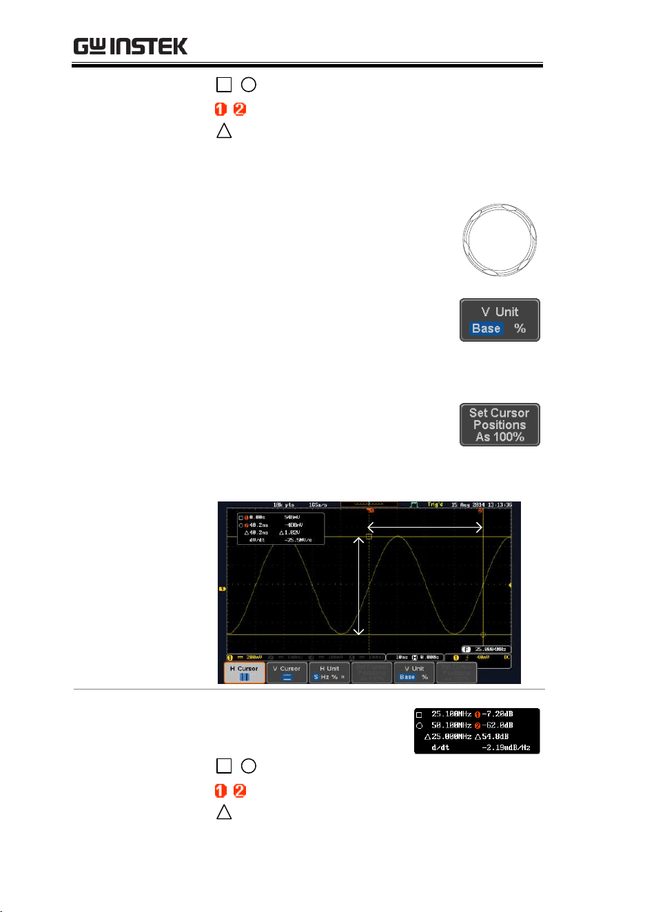
Use Vertical Cursors
Panel Operation/
Range
1. Press the Cursor key twice.
Cursor
x2
2. Press V Cursor from the bottom
menu if it is not already selected.
3. When the V Cursor is selected,
repeatedly pressing the V Cursor
key or the Select key will toggle
which vertical cursor is selected.
OR
Select
Range
Upper cursor movable, lower
cursor position fixed
Lower cursor movable, upper
cursor position fixed
Upper and lower cursor movable
together
4. The cursor position
information appears on the
top left hand side of the
screen.
MDO-2000E series User Manual
64
,
Time: cursor 1, cursor 2
,
Voltage/Current: cursor1, cursor2
Delta (difference between cursors)
dV/dt or dI/dt
5. Use the Variable knob to move the
cursor(s) up or down.
VARIABLE
Select Units
6. To change the units of the vertical
position, press V Unit.
Units
Base (source wave units), % (ratio)
Base or Ratio
Reference
7. To set the 0% and 100% ratio
references for the current cursor
position, press Set Cursor Positions
As 100%.
Example
Horizontal
cursors
Vertical
cursors
FFT
FFT has different content. For
FFT details, see page 69.
,
Frequency/Time: cursor1, cursor2
,
dB/V: cursor1, cursor2
Delta (difference between cursors)

MDO-2000E series User Manual
66
Example
Horizontal
cursors
Vertical
cursors

MEASUREMENT
67
Math Operation
Basic Math Overview & Operators
Background
The Math function performs basic math functions
(addition, subtraction, multiplication, division) on
the input signals or the reference waveforms. The
resultant waveform will be shown on the screen in
real-time.
Addition (+)
Adds the amplitude of two signals.
Source
CH1~4, Ref1~4
Subtraction (–)
Extracts the amplitude difference between two
signals.
Source
CH1~4, Ref1~4
Multiplication (×)
Multiplies the amplitude of two signals.
Source
CH1~4, Ref1~4
Division (÷)
Divides the amplitude of two signals.
Source
CH1~4, Ref1~4
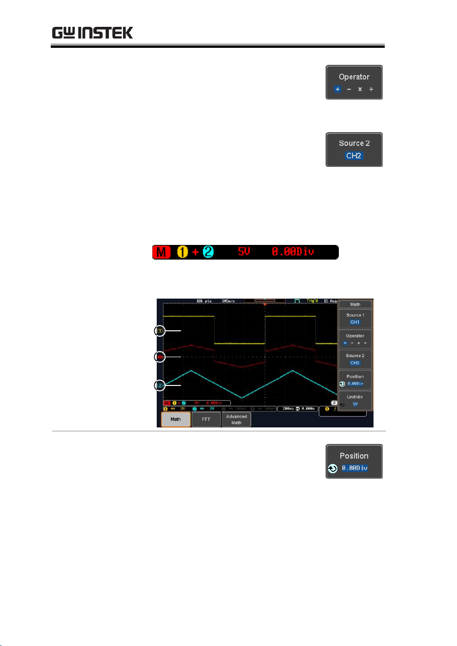
Addition/Subtraction/Multiplication/Division
Panel Operation
1. Press the Math key.
MATH
M
2. Press the Math key on the lower
bezel.
3. Select Source 1 from the side menu
Range
CH1~4, Ref1~4
MDO-2000E series User Manual
68
4. Press Operator to choose the math
operation.
Range
+, -, ×, ÷
5. Select Source 2 from the side menu.
Range
CH1~4, Ref1~4
6. The math measurement result appears on the
display. The vertical scale of the math
waveform appears at the bottom of the screen.
From left: Math function, source1, operator,
source2, Unit/div
Example
Math
Source 2
Source 1
Position and Unit
To move the math waveform
vertically, press the Position key from
the side menu and use the Variable
knob to set the position.
Range
–12.00 Div ~ +12.00 Div

MEASUREMENT
69
To change the unit/div settings, press
Unit/div, then use the Variable knob to
change the unit/div.
The units that are displayed depend
on which operator has been selected,
and whether the probe for the selected
channel has been set to voltage or
current.
Operator:
Unit/div:
Multiplication
Division
Addition/Subtraction
VV, AA or W
V/V, A/A
V or A
Turn Off Math
To turn off the Math result from the
display, press the Math key again.
MATH
M
FFT Overview & Window Functions
Background
The FFT function performs a Fast Fourier
Transform on one of the input signals or the
reference waveforms. The resultant spectrum will
be shown on the screen in real-time. Four types of
window function are available: Hanning,
Hamming, Rectangular, and Blackman, as
described below.
Hanning
Frequency resolution
Good
Amplitude resolution
Not good
Suitable for....
Frequency measurement on
periodic waveforms
Hamming
Frequency resolution
Good
Amplitude resolution
Not good
MDO-2000E series User Manual
70
Suitable for....
Frequency measurement on
periodic waveforms
Rectangular
Frequency resolution
Very good
Amplitude resolution
Bad
Suitable for....
Single-shot phenomenon
(this mode is the same as
having no window at all)
Blackman
Frequency resolution
Bad
Amplitude resolution
Very good
Suitable for....
Amplitude measurement on
periodic waveforms
(Note)
For more complete measures and functions in the
frequency domain of a signal, please also refer to
the Spectrum Analyzer section of the MDO-2000E
series on page 247.
FFT Operation
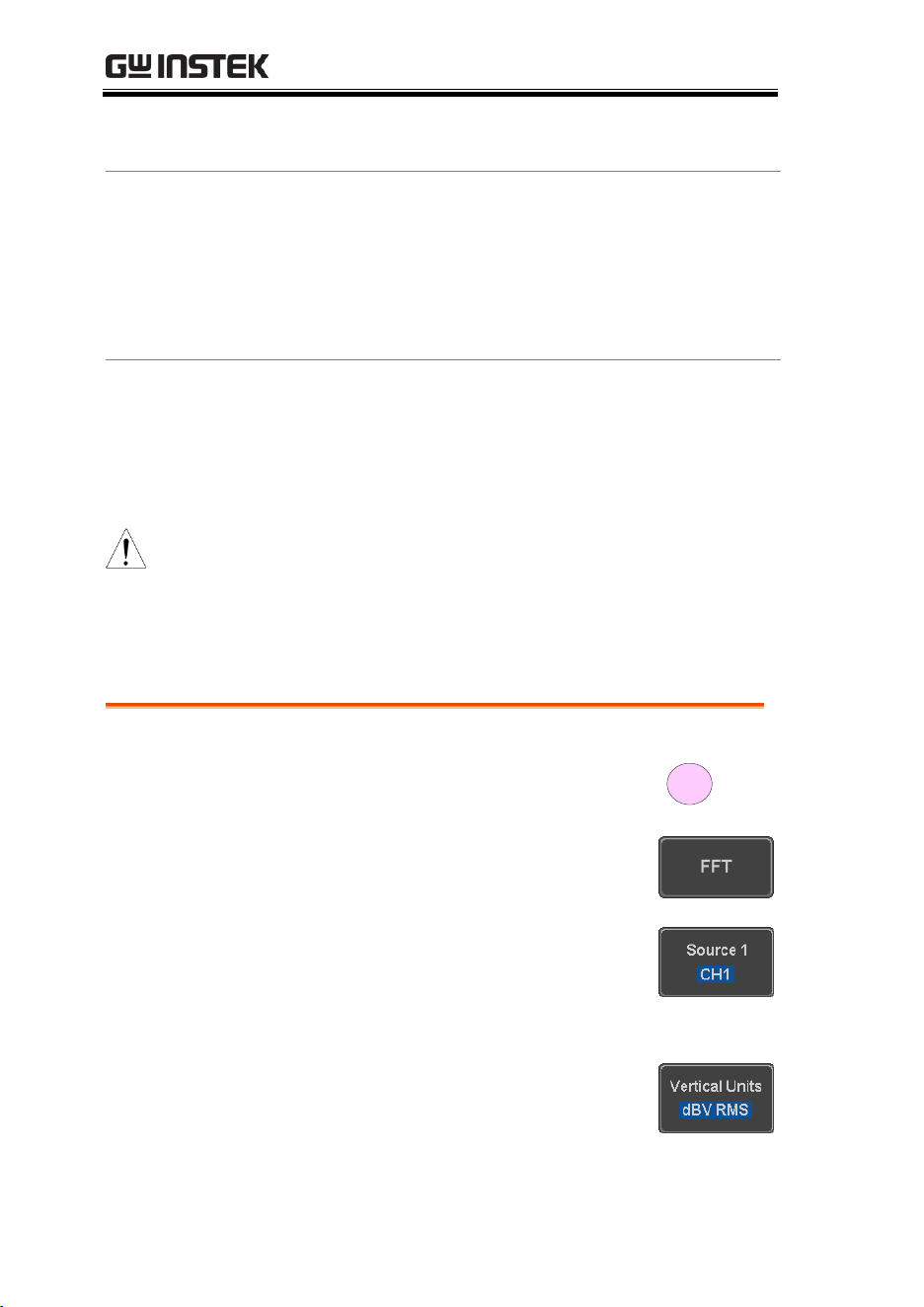
Panel Operation
1. Press the Math key.
MATH
M
2. Press FFT from the bottom menu.
3. Select the Source from the side
menu.
Range
CH1~4, Ref~4
4. Press the Vertical Units key from
the side menu to select the vertical
units used.
Range
Linear RMS, dBV RMS
MEASUREMENT
71
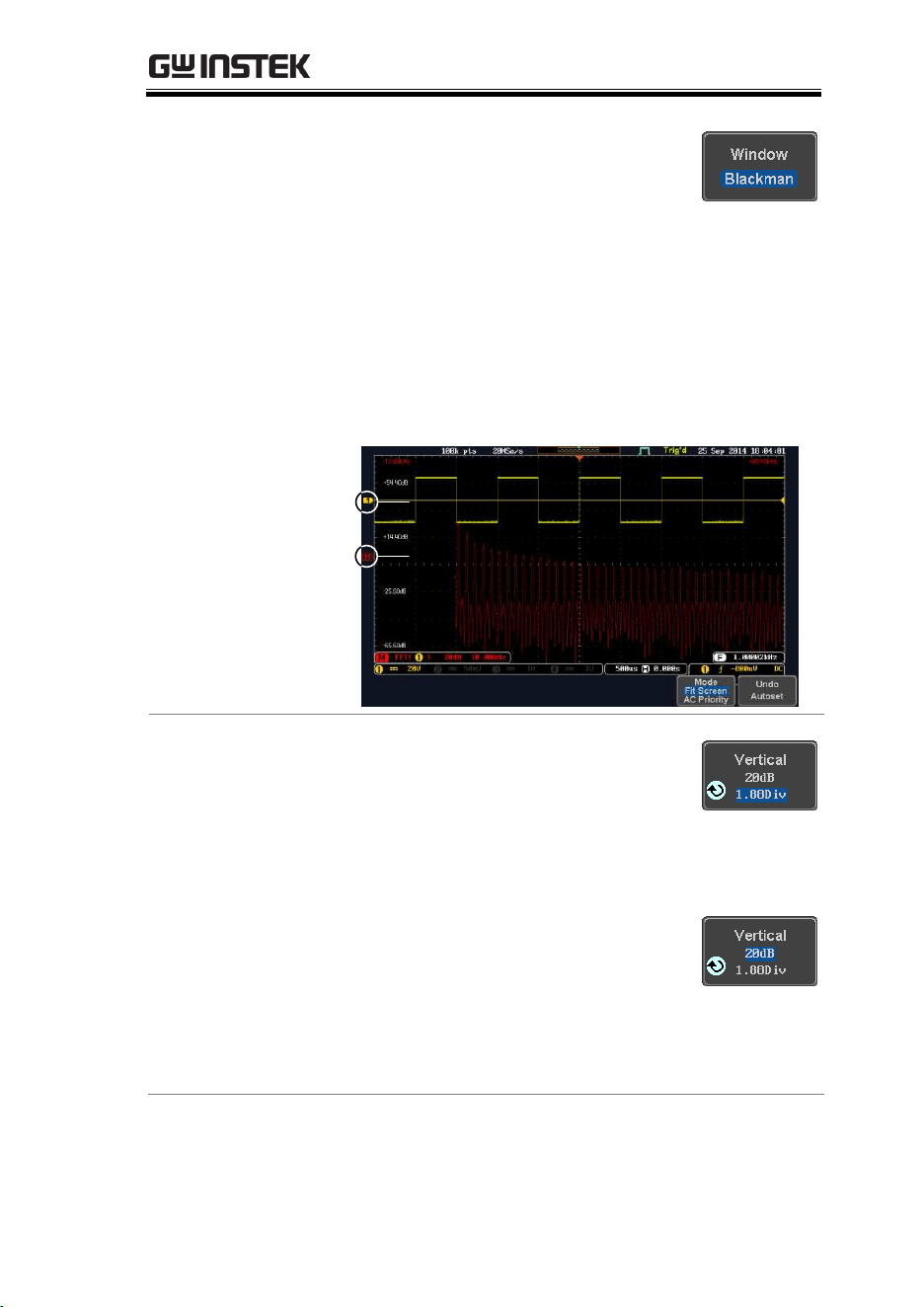
5. Press the Window key from the side
menu and select the window type.
Range
Hanning, Hamming, Rectangular,
and Blackman.
6. The FFT result represents the frequency-
domain representation of a signal. Hence, the
horizontal scale changes from time to
frequency, and the vertical scale from
voltage/current to dB/RMS.
Math
Source
Position and
Scale
To move the FFT waveform vertically,
press Vertical until the Div parameter
is highlighted and then use the
Variable knob.
Range
–12.00 Div ~ +12.00 Div
To select the vertical scale of the FFT
waveform, press Vertical until the dB
or voltage parameters are highlighted
and then use the Variable knob.
Range
2mV~1kV RMS (Linear RMS),
1~20 dB (dB VRMS)

MDO-2000E series User Manual
72
Horizontal
Position and
Scale
To move the FFT waveform
horizontally, press Horizontal until the
Frequency parameter is highlighted
and then use the Variable knob.
Range
0Hz ~ half of the sampling
frequency
To select the horizontal scale of the
FFT waveform, press Horizontal
repeatedly until the Hz/div parameter
is highlighted and then use the
Variable knob.
Advanced Math Overview
Background
The advanced math function allows complex math
expressions to be created based on the input
sources, reference waveforms or even the
automatic measurements available from the
Measure menu (see page 46).
An overview of each of the major parameters that
can be used in the advanced math function are
shown below:
Expression
Displays the function expression as it is created.
Source
Selects the source signal.
Source
CH1~4, Ref1~4
Function
Adds a mathematical function to the expression.
Function
Intg, Diff, log, Ln, Exp, Sqrt, Abs,
Rad, Deg, Sin, Cos, Tan, Asin,
Acos, Atan
Variable
Adds a user-specified variable to the expression.
Source
CH1~4, Ref1~4

MEASUREMENT
73
Operator
Adds an operator or parenthesis to the function
expression.
Operator
+, -, *, /, (, ), !(, <, >, <=, >=, ==, !=,
||, &&
Figure
Adds a value to the expression.
Figure
Integers, floating point, or floating
point with exponent values.
Measurement
Adds automatic measurements to the expression.
Not all automatic measurements are supported.
Measurement
Pk-Pk, Max, Min, Amp, High,
Low, Mean, CycleMean, RMS,
CycleRMS, Area, CycleArea,
ROVShoot, FOVShoot, Freq,
Period, Rise, Fall, PosWidth,
NegWidth, Dutycycle, FRR, FRF,
FFR, FFF, LRR, LRF, LFR, LFF,
Phase, RPRFShoot, FPREShoot,
+Pulses, -Pulses, +Edges, -Edges
Advanced Math Operation
Panel Operation
1. Press the Math key.
M
MATH
2. Press Advanced Math from the
bottom menu.
3. Press Edit Expression.
4. The Edit f(x) screen appears. CH1 + CH2 is
shown in the expression box as an example at
startup.
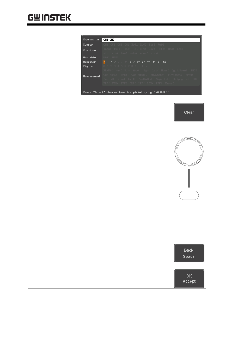
MDO-2000E series User Manual
74
5. Press Clear to clear the expression
entry area.
6. Use the Variable knob and the Select
key to create an expression.
Use the Variable knob to highlight a
source, function, variable,
operator, figure or measurement in
orange.
Press the Select key to make the
selection.
If a particular parameter is grayed
out, it indicates that the particular
parameter is not available at that
time.
Select
VARIABLE
Back Space
7. To delete the last parameter press
Back Space.
8. When the expression is complete,
press OK Accept.
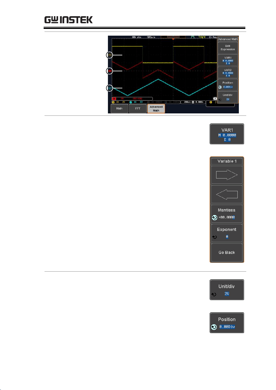
MEASUREMENT
75
Example:
CH1 + CH2
Advanced Math
Source1
Source2
Set the VAR1 &
VAR2
9. Press VAR1 or VAR2 to set
VAR1/VAR2 if they were used in
the expression created previously.
10. Press Mantissa.
Use the Left and Right arrow keys
to select a digit and use the
variable knob to set the value of
the selected digit.
11. Press Exponent.
Use the Variable knob to set the
exponent of the variable.
12. Press Go Back to finish editing
VAR1 or VAR2.
Vertical Position
and Scale
13. Press Unit/div and use the Variable
knob to set the vertical scale of the
math waveform.
14. Press Position and use the Variable
knob to set the vertical position of
the math waveform on the display.

MDO-2000E series User Manual
76
Clear Advanced
Math
To clear the advanced math result
from the display, press the Math key
again.
MATH
M

ADVANCED CONFIGURATION
77
ADVANCED
CONFIGURATION
Acquisition ................................................................ 80
Select Acquisition Mode ........................................................................ 80
Show Waveform in XY Mode ............................................................. 81
Set the Record Length ........................................................................... 83
Segmented Memory Acquisition ................................ 85
Segments Display ................................................................................... 86
Set the Number of Segments ............................................................... 87
Run Segmented Memory ....................................................................... 88
Navigate Segmented Memory .............................................................. 90
Play Through Each Segment ................................................................ 91
Measurement on Segments ................................................................... 91
Segment Info ........................................................................................... 95
Display ...................................................................... 97
Display Waveform as Dots or Vectors............................................... 97
Set the Level of Persistence .................................................................. 97
Set the Intensity Level ........................................................................... 98
Select Display Graticule ........................................................................ 99
Freeze the Waveform (Run/Stop) .................................................... 100
Turn Off Menu ..................................................................................... 101
Horizontal View ........................................................102
Move Waveform Position Horizontally ........................................... 102
Select Horizontal Scale ........................................................................ 103
Select Waveform Update Mode ......................................................... 104
Zoom Waveform Horizontally .......................................................... 105
Play/Pause ............................................................................................. 107
Vertical View (Channel) .............................................110
Move Waveform Position Vertically ................................................. 110
Select Vertical Scale .............................................................................. 111
Select Coupling Mode .......................................................................... 111
Input Impedance .................................................................................. 112
Invert Waveform Vertically ................................................................ 112

MDO-2000E series User Manual
78
Limit Bandwidth ................................................................................... 113
Expand by Ground/Center ................................................................ 114
Select Probe Type ................................................................................. 115
Select Probe Attenuation Level .......................................................... 116
Set the Deskew ...................................................................................... 116
Bus Key Configuration .............................................. 118
Bus Display ............................................................................................ 118
Serial Bus Overview ............................................................................. 119
UART Serial Bus Configuration ........................................................ 122
I
2
C Serial Bus Interface ....................................................................... 124
SPI Serial Bus Interface ....................................................................... 126
CAN Serial Bus Interface .................................................................... 128
LIN Serial Bus Interface ...................................................................... 129
Parallel Bus ............................................................................................ 131
Bus Encoding ........................................................................................ 133
Threshold configuration ...................................................................... 133
Serial Bus Event Tables ....................................................................... 135
Event Tables Format ........................................................................... 138
Adding a Label to a Bus ...................................................................... 139
Using Cursors with the Serial Bus or Parallel Bus .......................... 141
Trigger ..................................................................... 143
Trigger Type Overview........................................................................ 143
Trigger: types and sources ................................................................... 145
Trigger Parameter Overview .............................................................. 146
Setup Holdoff Level ............................................................................. 153
Setup Trigger Mode ............................................................................. 154
Using the Edge Trigger ....................................................................... 154
Using Advanced Delay Trigger .......................................................... 156
Using Pulse Width Trigger .................................................................. 157
Using Video Trigger ............................................................................. 159
Pulse Runt trigger ................................................................................. 161
Using Rise and Fall Trigger ................................................................. 162
Using the Timeout Trigger ................................................................. 164
Using the Bus Trigger .......................................................................... 166
UART BUS Trigger Settings ..................................................... 166
I
2
C Bus Trigger Settings ............................................................ 168
SPI Bus Trigger Settings ............................................................ 171
CAN Bus Trigger ........................................................................ 172
LIN Bus Trigger .......................................................................... 175
Parallel Bus Trigger .................................................................... 177
Using the Logic Trigger ....................................................................... 178
Search ...................................................................... 183
Configuring Search Events ................................................................. 183

ADVANCED CONFIGURATION
79
Copying Search Event To/From Trigger Events .......................... 185
Search Event Navigation..................................................................... 185
Save Search Marks ................................................................................ 186
Setting/Clearing Single Search Events ............................................. 187
FFT Peak................................................................................................ 188
System Settings and Miscellaneous Settings ............192
Select Menu Language ......................................................................... 192
View System Information ................................................................... 192
Erase Memory ....................................................................................... 193
Set Date and Time ................................................................................ 194
Probe Compensation Frequency ....................................................... 194
QR Code Reader Function ................................................................. 195

MDO-2000E series User Manual
80
Acquisition
The Acquisition process samples the analog input signals and
converts them into digital format for internal processing.
Select Acquisition Mode
Background
The acquisition mode determines how the samples
are used to reconstruct a waveform.
Sample
This is the default acquisition
mode. Every sample from each
acquisition is used.
Peak detect
Only the minimum and maximum
value pairs for each acquisition
interval (bucket) are used. This
mode is useful for catching
abnormal glitches in the signal.
Average
Multiple acquired data is
averaged. This mode is useful for
drawing a noise-free waveform.
To select the average number, use
the Variable knob.
Average number: 2, 4, 8, 16, 32, 64,
128, 256
Panel Operation
1. Press the Acquire key.
Acquire
2. To set the Acquisition mode, press
Mode on the bottom menu.
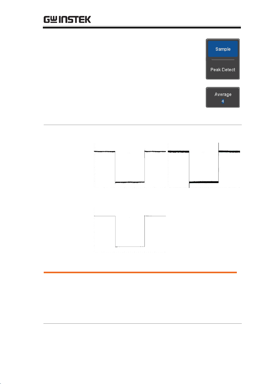
ADVANCED CONFIGURATION
81
3. Select an acquisition mode from
the side menu.
4. If Average was chosen, set the
number of samples to be used for
the average function.
Mode
Sample, Peak Detect,
Average
Average
sample
2, 4, 8, 16, 32, 64, 128,
256
Example
Sample
Peak Detect
Average (256 times)
Show Waveform in XY Mode
Background
The XY mode maps the input of channel 1 to the
input of channel 2. In 4 channel models, the input
of channel 3 can be mapped to the input of channel
4. This mode is useful for observing the phase
relationship between waveforms.
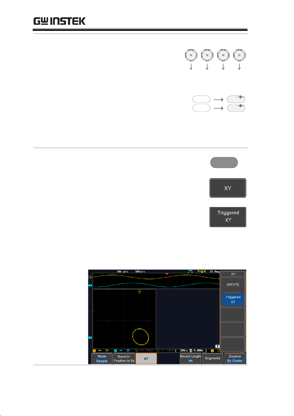
MDO-2000E series User Manual
82
Connection
1. Connect the signals to
Channel 1 (X-axis) and
Channel 2 (Y-axis) or
Channel 3 (X2-axis) and
Channel 4 (Y2-axis).
CH3CH2CH1 CH4
YX X2 Y2
2. Make sure a channel pair is
active (CH1&CH2 or
CH3&CH4). Press the
Channel key if necessary. A
channel is active if the
channel key is lit.
CH1 CH1
CH2 CH2
Panel Operation
3. Press the Acquire menu key.
Acquire
4. Press XY from the bottom menu.
5. Choose Triggered XY from the side
menu.
X-Y mode is split into two windows. The top window
shows the signals over the full time range. The bottom
window shows XY mode.
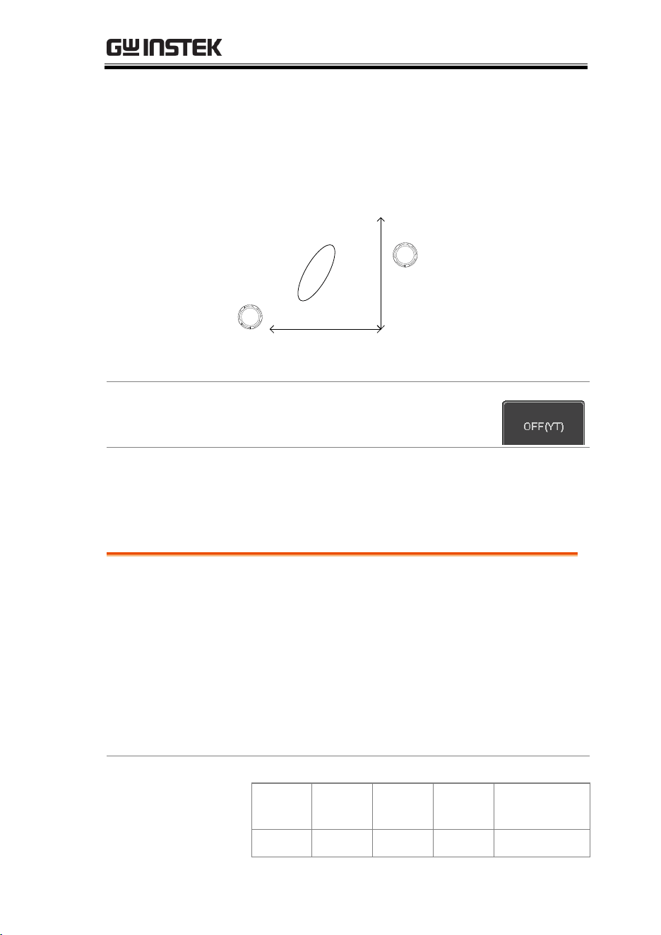
ADVANCED CONFIGURATION
83
To move the XY waveform position, use the
vertical position knob: Channel 1 knob moves the
XY waveform horizontally and Channel 2 knob
moves the XY waveform vertically. Similarly, the
X2 and Y2 axis can be positioned using the channel
3 and channel 4 vertical position knobs.
POSITION
CH1
POSITION
CH2
The horizontal position knob and horizontal Scale
knob can still be used under the XY mode.
Turn Off XY Mode
To turn off XY mode, choose OFF (YT)
mode.
Cursors and XY
Mode
Cursors can be used with XY mode.
See the Cursor chapter for details.
Page 60
Set the Record Length
Background
The number of samples that can be stored is set by
the record length. Record length is important in an
oscilloscope as it allows longer waveforms to be
recorded.
The maximum record length for the MDO-2000E
SERIES depends on operating mode. The table
below describes the record lengths that are
available for each mode.
Limitations
Record
Length
Normal
Zoom
FFT
FFT in Zoom
Window
1k
✓
✗
✓
✗
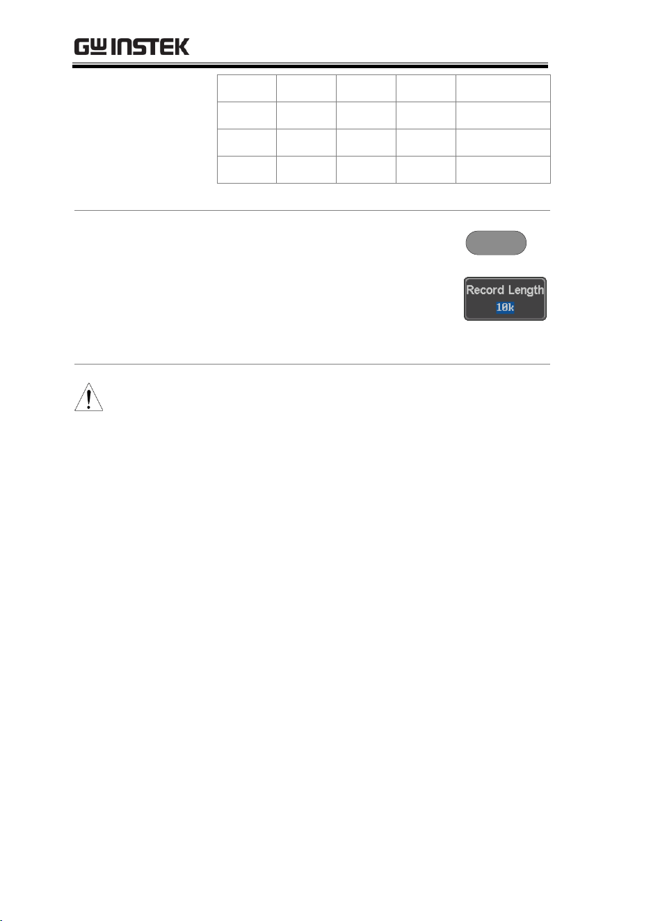
MDO-2000E series User Manual
84
10k
✓
✓
✓
✓
100k
✓
✓
✓
✓
1M
✓
✓
✓
✗
10M
✓
✓
✗
✗
Panel Operation
1. Press the Acquire key.
Acquire
2. Press the Record Length key on the
bottom menu and choose the
record length.
Record length
1000, 10k, 100k, 1M, 10M points
Note
The sampling rate may also be changed when the
record length is changed.
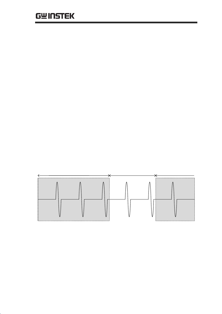
ADVANCED CONFIGURATION
85
Segmented Memory Acquisition
The advanced segmented memory utility allows the scope memory
to be divided into different segments. Each time the scope is
triggered, it only acquires data for one segment of memory at a
time. This allows you to optimize the scope memory to only
perform signal acquisition during important signal events.
For example, for a signal with a number of pulses, normally the
oscilloscope will acquire the signal until the acquisition memory of
the scope is filled up and then it will re-arm the trigger and then
capture again. This could result in a number of events not being
captured or captured at a less-than-desired resolution (depending
on the horizontal scale and sampling rate). However, the
segmented memory function would effectively allow you to
capture more of the signal than you would otherwise. The
diagrams below illustrate this point.
Normal acquisition mode example:
Normal memory acquisition period Rearm time Next trigger
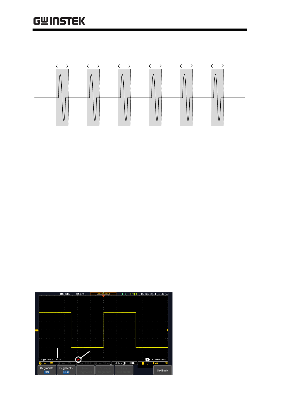
MDO-2000E series User Manual
86
Segmented memory acquisition example:
Segment
n
Segment
n+1
Segment
n+2
Segment
n+3
Segment
n+4
Segment
n+5
As shown above, the memory is divided into segments to increase
the number of events that can be effectively captured with the same
acquisition memory. Also notice that the scope doesn’t need to
rearm the trigger between each segment, this makes the segmented
memory function especially useful for high speed signals. The time
between each segment is also recorded so that accurate signal
timing can also be measured.
The segmented memory function also supports automatic
measurements for each segment or statistics for all the captured
segments.
The advanced Segment Memory Utility is available for both analog
and digital channels.
Segments Display
Run/Stop Indicator
Progress Indicator
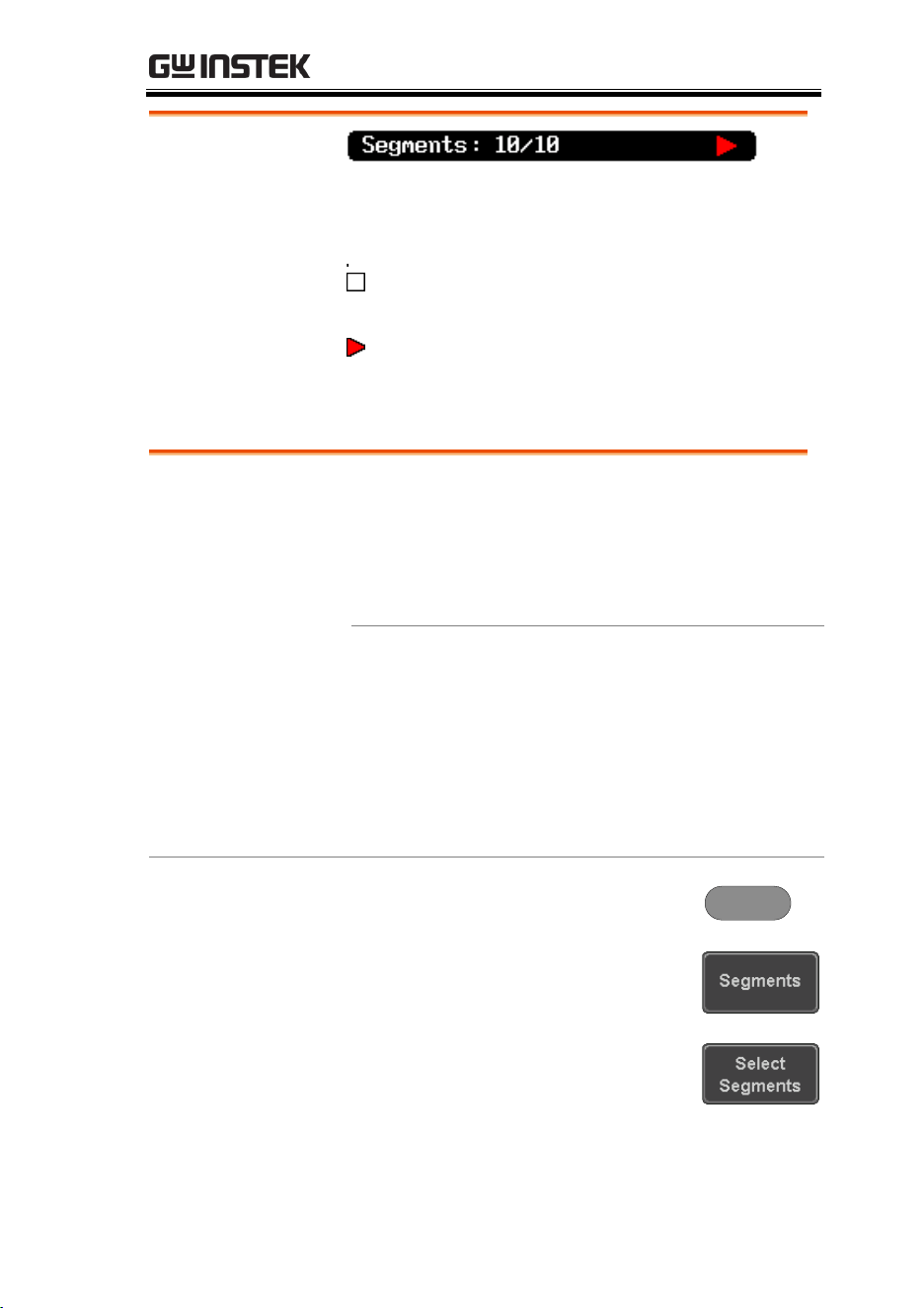
ADVANCED CONFIGURATION
87
Progress Indicator
Indicates the number of segments that have to
been captured relative to the set number of
segments.
Run/Stop Indicator
Stop: The segments have finished
acquiring or have been stopped.
Run: The scope is ready to acquire
segments.
Set the Number of Segments
Note
Before the Segment function can be used, set the
trigger settings as appropriate for the signal you
wish to use. The number of segments that can be
used depends wholly on the record length. See
page 83 to set the record length.
Record length
Number of segments
1000 pt.
1 ~ 29000
10k pt.
1 ~ 2900
100k pt.
1 ~ 290
1M pt.
1 ~ 20
10M pt.
1 ~ 2
Panel Operation
1. Press the Acquire key.
Acquire
2. Press Segments on the bottom
menu.
3. Press Select Segments and set the
number of segments from the side
menu.
Num of Seg
1~29000 (record length
dependant)
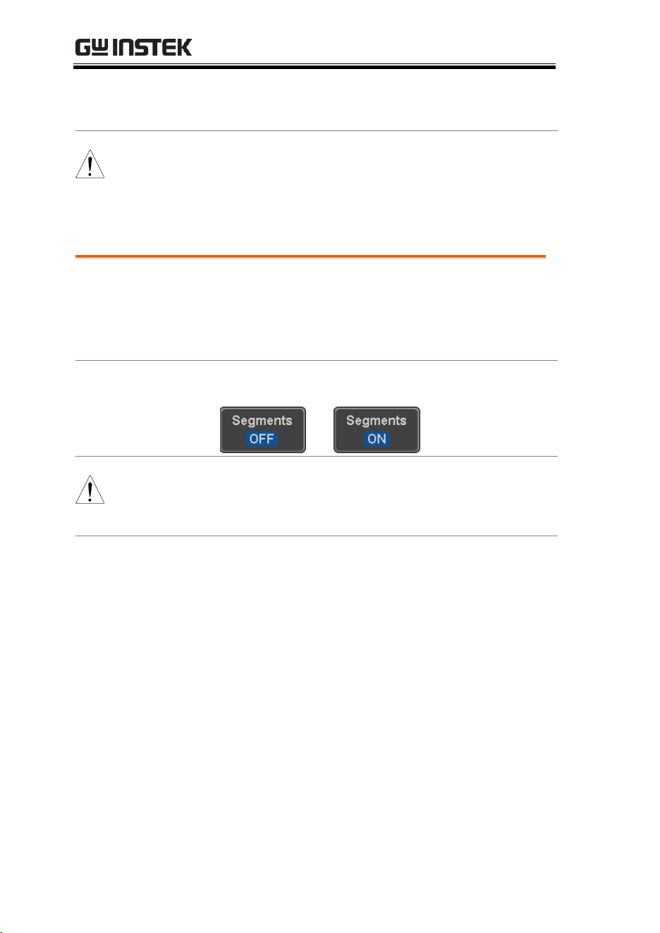
MDO-2000E series User Manual
88
Set to Maximum
Sets to the maximum number
Set to Minimum
Sets to 1 segment
Note
The Select Segments icon is only available when
Segments = OFF or when Segments is in the STOP
mode (see the section below).
Run Segmented Memory
Background
Before the Segmented Memory function can be
used, set the trigger settings as appropriate for the
signal you wish to use. See page 143 for
configuring the trigger settings.
Run Segments
1. Toggle Segments On from the bottom menu.
Note
The first time Segmented memory is turned on the
segments will automatically be run. Each segment
will be automatically captured.
2. The scope will automatically start acquiring
segments. The progress of the segmented
memory capture is shown in the Progress
Indicator.
3. The Run Indicator will be shown when in the
Run mode and the Segments icon will also
indicate that the function is in run mode.
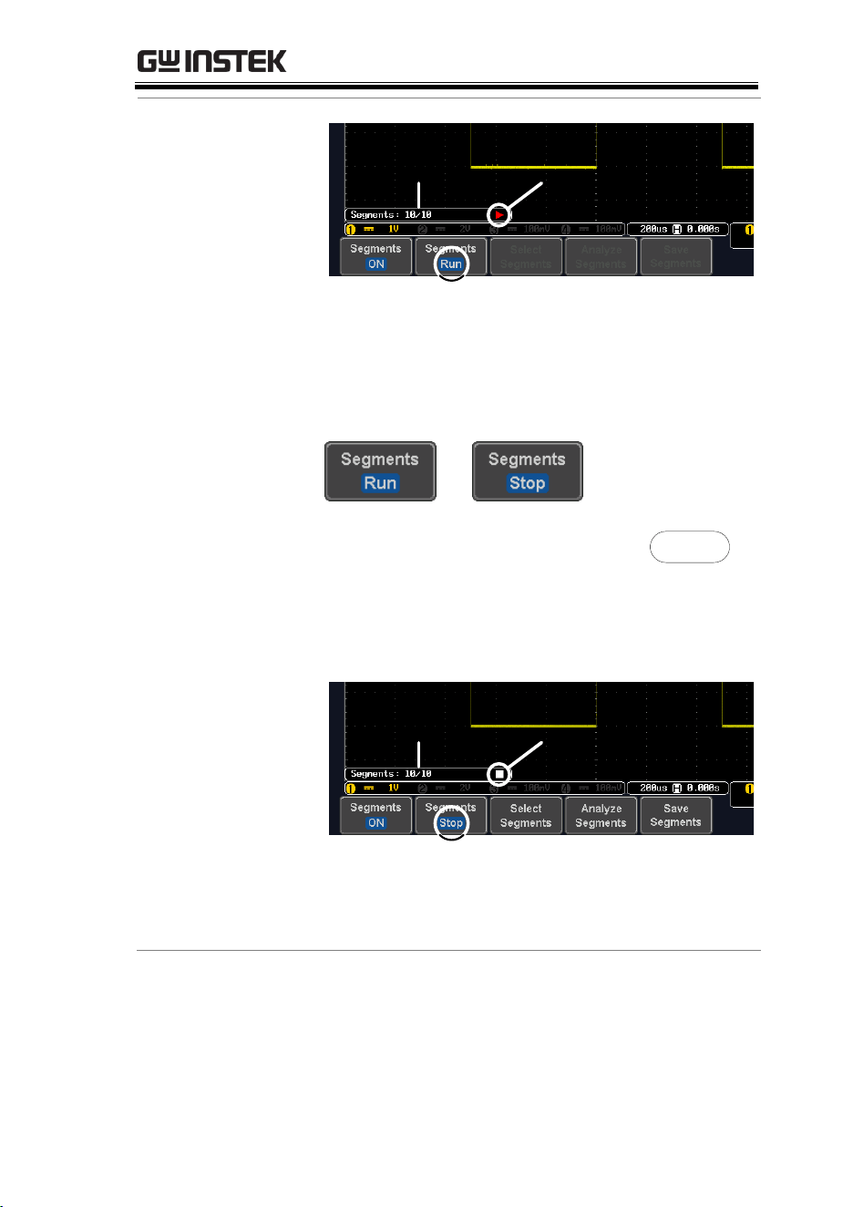
ADVANCED CONFIGURATION
89
Run Indicator
Progress Indicator
Segment (Run )icon
4. When the scope has finished acquiring
segments, press Segments Run to toggle the
mode to the Segments Stop mode.
Alternatively, the Run/Stop key can
be pressed.
Run/Stop
5. The Stop Indicator will be shown when in the
Stop mode.
Stop Indicator
Progress Indicator
Segment (Stop )icon
The scope is now ready to navigate or analyze the
acquired segments.
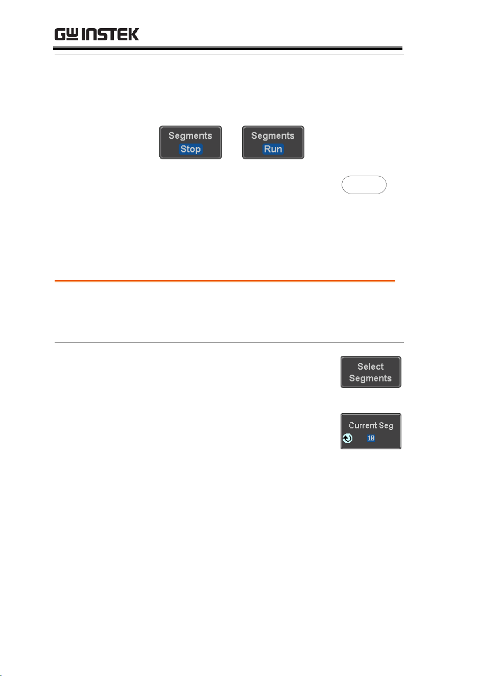
MDO-2000E series User Manual
90
Rerun Segmented
Acquisition
6. To rerun the segments, press the Segments Stop
key to toggle the mode back to the Segments
Run mode.
Alternatively, press the Run/Stop
key again.
Run/Stop
7. Repeat steps 3 and 4 in the section above when
the segmented acquisition has completed.
Navigate Segmented Memory
Background
After the segmented memory acquisitions have
been captured you can navigate through each
segment one at a time.
Operation
1. Press Select Segments from the
bottom menu. This key will be
available in the Stop mode.
2. To navigate to the segment of
interest, press Current Seg from the
side menu and use the Variable
knob to scroll to the segment of
interest.
Alternatively, the Set to Minimum
and Set to Maximum keys can be
used to jump to the first and last
segment respectively.

ADVANCED CONFIGURATION
91
3. The position in time of the selected
segment relative to the time of the
first segment is shown in the
Segments Time key.
Play Through Each Segment
Background
When all the segments have been acquired, the
play/pause key can be used to play back through
each segment.
Operation
1. Make sure the scope is in Segments Stop mode.
See page 88 for details.
2. Press the Play/Pause key to run
through the acquired segments in
numerical order.
Press the Play/Pause key again
to pause the playback.
When the scope has played
through to the last segment,
pressing the Play/Pause key
again will play through each
segment again in reverse order.
Measurement on Segments
Background
The Segmented memory function can be used in
conjunction with the automatic measurements
configured in the Measurement menu (see page
46).
Please note that Digital channels measurements
cannot be used in conjunction with the segmented
memory.

MDO-2000E series User Manual
92
Modes
Segments
Measure
This function will either perform
statistics calculations on the
segments or tabulate a list of the
measurement results for all the
segments.
Segments
Info
Provides configuration information
common for all the acquired memory
segments.
Segments
Measure
The Segments Measure function allows you to
view automatic measurements for the segments in
statistical bins or as a list displaying the result of
each automatic measurement.
Statistics
This function will bin the
measurement results of a single
automatic measurement into a
user-defined number of bins.
This allows you to easily view
statistics for a large number of
segments. For example, the
statistics function will display
the number of results for each
bin and the measurement range
of each bin for the selected
automatic measurement.
Measurement
List
Puts all the measurement
results for a segment in a list.
All the currently selected
automatic measurement results
are listed. A maximum of 8
automatic measurements can be
used with this function.
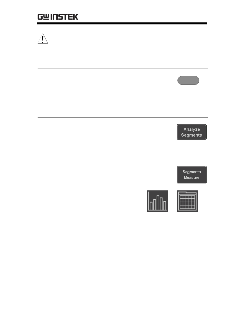
ADVANCED CONFIGURATION
93
Note
To use automatic measurements with the
segmented memory, automatic measurements
must first be selected from the Measure menu
before the segmented memory function is run.
Note that Digital channels cannot use this function.
Setup
Press the Measure key and select
any single source measurement
from the Add Measurement menu.
See page 50 for details on how to
add automatic measurements.
Measure
Operation
1. Press Analyze Segments from the
Segments menu.
Note: This key will only be
available in the Stop mode.
2. Press Segments Measure.
3. Select either the
statistics or the
measurement list from
the side menu.
Statistics
List
4. The statics table or measurement list appears on
the display.
Note that the more segments that you have, the
longer it will take to calculate the statics or list
the measurement results.
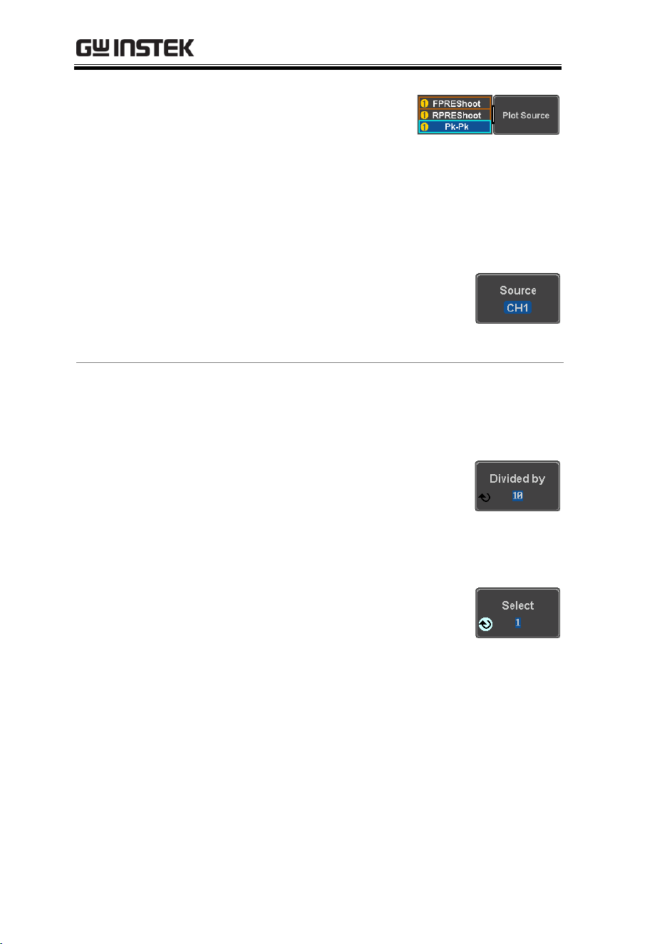
MDO-2000E series User Manual
94
5. For statistic measurements,
press Plot Source to choose
which automatic
measurement to use for the
statistics calculations. The
statistics for only one
automatic measurement
can be viewed at a time.
6. For the measurement list, press
Source and select the source
channel for measurement.
Range
CH1 ~ CH4
Statistics Results
This function will bin the measurement results of
the selected automatic measurement into a user-
defined number of bins.
Setup
7. To select the number of bins for the
statistics, press Divided by and
select the number of bins with the
Variable knob.
Range
1~20 bins
8. Press Select and use the Variable
knob to view the measurement
results for each bin.
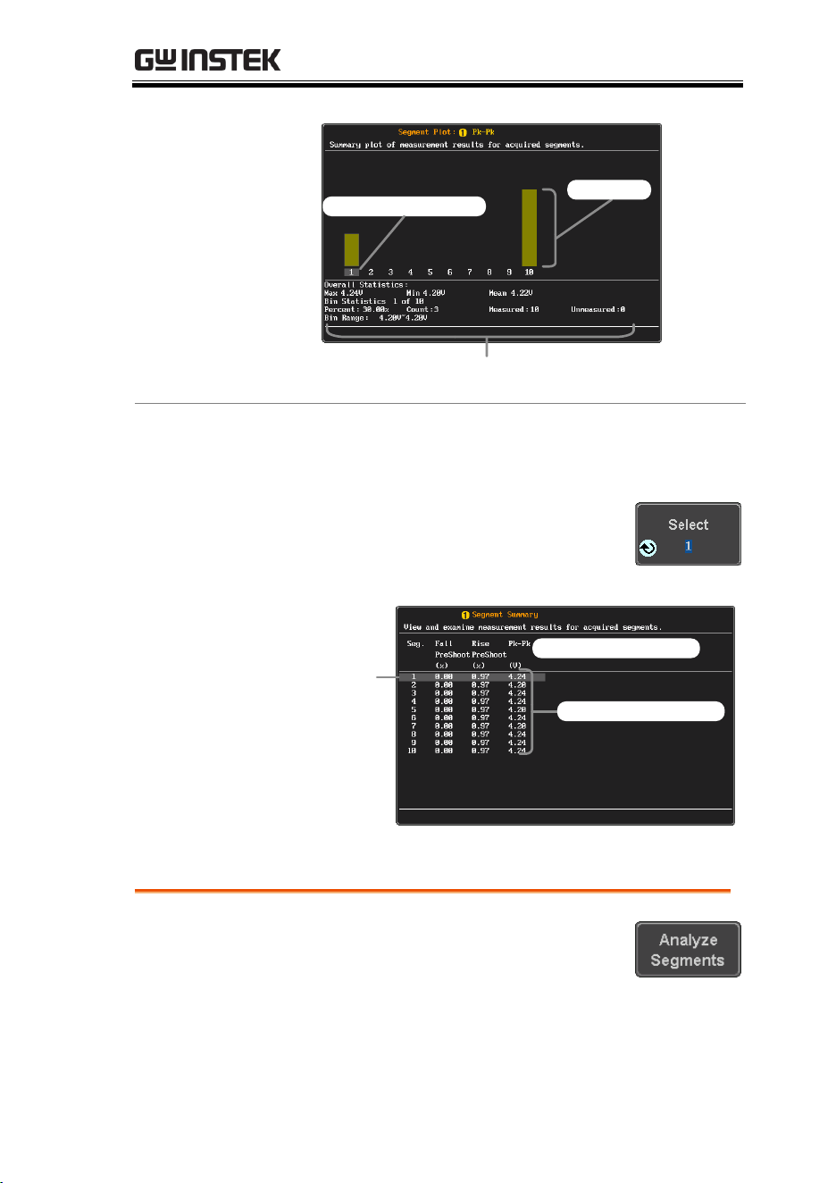
ADVANCED CONFIGURATION
95
Example:
Statistics
Statistics of currently
selected bin
Cursor/selected bin
Bin count
Measurement
List
Puts all the measurement results for a segment in a
list.
Setup
9. Press Select and use the variable
knob to scroll through each
segment.
Example:
Measurement
List
Select
cursor
Measurement results
Measurement types
Segment Info
Operation
1. Press Analyze Segments from the
bottom menu.
Note: This key will only be
available in the Stop mode.

MDO-2000E series User Manual
96
2. Press Segments Info.
3. A table showing all general setting information
for the segmented memory acquisitions is
shown on the display.
Info:
Sample rate, Record length,
Horizontal, Vertical
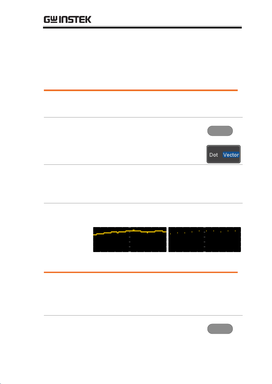
ADVANCED CONFIGURATION
97
Display
The Display menu defines how the waveforms and parameters
appear on the main LCD display.
Display Waveform as Dots or Vectors
Background
When the waveform is displayed on the screen, it
can be displayed as dots or vectors.
Panel Operation
1. Press the Display menu key.
Display
2. Press Dot / Vector to toggle between
Dot and Vector mode.
Range
Dots
Only the sampled dots are
displayed.
Vectors
Both the sampled dots and the
connecting line are displayed.
Example:
Vectors
Dots
Set the Level of Persistence
Background
The persistence function allows the MDO-2000E
SERIES to mimic the trace of a traditional analog
oscilloscope. A waveform trace can be configured
to “persist” for a designated amount of time.
Panel Operation
1. Press the Display menu key.
Display
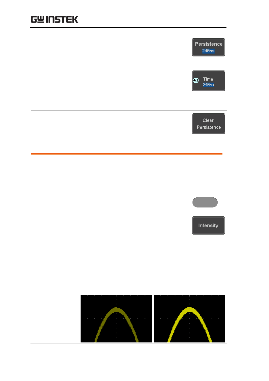
MDO-2000E series User Manual
98
2. To set the persistence time, press
the Persistence menu button on the
bottom bezel.
3. Use the Variable knob to select a
persistence time.
Time
16ms, 30ms, 60ms, 120ms, 240ms,
0.5s, 1s, 2s,~4s, Infinite, Off
Clear
To clear persistence, press Clear
Persistence.
Set the Intensity Level
Background
The intensity level of a signal can also be set to
mimic the intensity of an analog oscilloscope by
setting the digital intensity level.
Panel Operation
1. Press the Display menu key.
Display
2. Press Intensity from the bottom
menu.
Waveform
Intensity
3. To set the waveform intensity, press Waveform
Intensity and edit the intensity.
Range
0~100%
Example
Waveform Intensity 50%
Waveform Intensity 100%
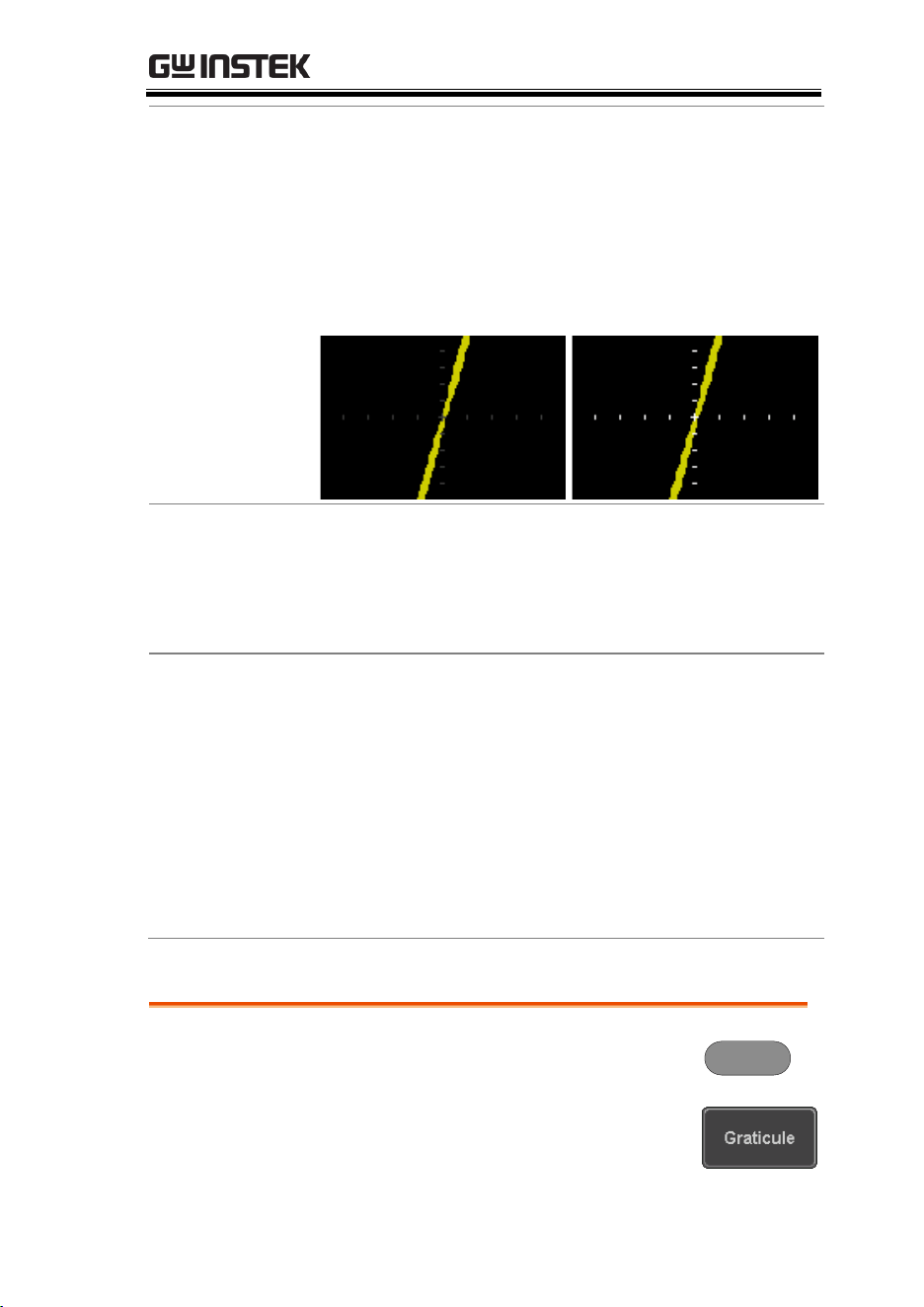
ADVANCED CONFIGURATION
99
Graticule
Intensity
4. To set the graticule intensity, press Graticule
Intensity from the side menu and edit the
intensity value.
Range
10~100%
Example
Graticule Intensity 100%
Graticule Intensity 10%
Backlight
Intensity
5. To set the LCD backlight intensity, press
Backlight Intensity from the side menu and edit
the intensity value.
Range
2~100%
Backlight Auto-
Dim
6. To automatically dim the backlight after a set
duration, set Backlight Auto-Dim to On and then
set Time to the appropriate time.
After the set amount of time with no panel
activity, the screen will dim until a panel key is
pressed again. This function will prolong the
life of the LCD display.
Range
1~180 min
Select Display Graticule
Panel Operation
1. Press the Display menu key.
Display
2. Press Graticule from the bottom
menu.
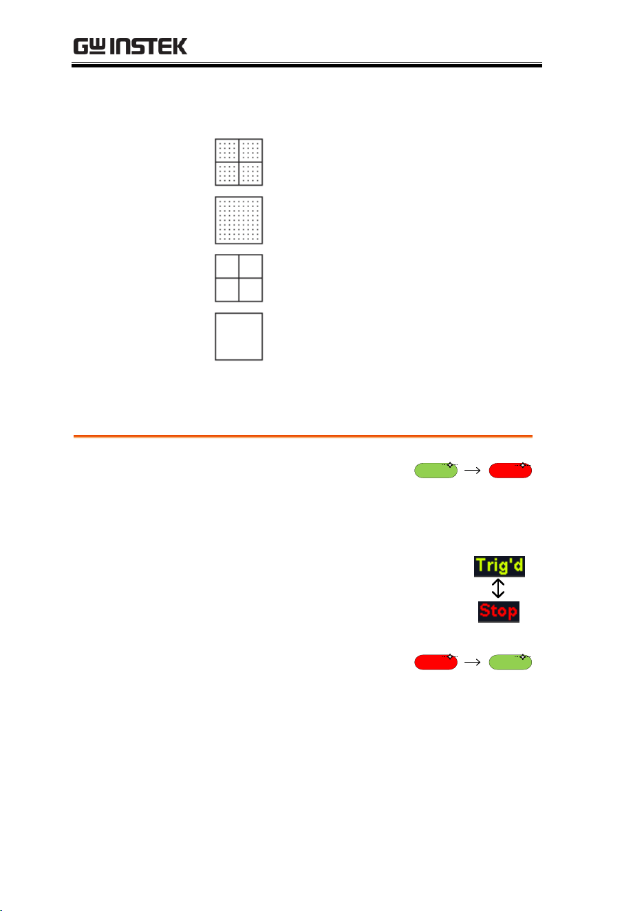
MDO-2000E series User Manual
100
3. From the side menu choose the
graticule display type.
Full
: Shows the full grid; X and Y axis
for each division.
Grid
: Show the full grid without the X
and Y axis.
Cross Hair
: Shows only the center X
and Y frame.
Frame
: Shows only the outer frame.
Freeze the Waveform (Run/Stop)
For more details about Run/Stop mode, see page 42.
Panel Operation
1. Press the Run/Stop key. The
Run/Stop key turns red and
waveform acquisition is
paused.
Run/Stop Run/Stop
2. The waveform and the trigger
freezes. The trigger indicator on
the top right of the display shows
Stop.
3. To unfreeze the waveform,
press the Run/Stop key
again. The Run/Stop key
turns green again and
acquisition resumes.
Run/Stop Run/Stop

ADVANCED CONFIGURATION
101
Turn Off Menu
Panel Operation
1. Press the Menu Off key
below the side menu keys to
reduce a menu. The menu
key needs to be pressed
each time to reduce one
menu.
See page 31 for more
information.
VARIABLE
POSITION
HORIZONTAL
POSITION
POSITION
POSITION
POSITION
VERTICAL
MATH
REF
BUS
SCALE
TRIGGER
LEVEL
PUSH TO
ZERO
SCALESCALESCALE
PUSH TO
ZERO
PUSH TO
ZERO
PUSH TO
ZERO
PUSH TO
ZERO
PUSH TO
ZERO
SCALE
POWER
CH1 CH2 CH3 CH4
2V
CAT I
1M
W
16pF
300Vpk MAX.
Measure
Display
Cursor
Help
Test
Save/Recall
Acquire
Utility
Autoset
Run/Stop
Single
Default
Select
Search
Set/Clear
Zoom
CH1 CH2 CH3 CH4
M
R
B
Menu
50 %
Force-Trig
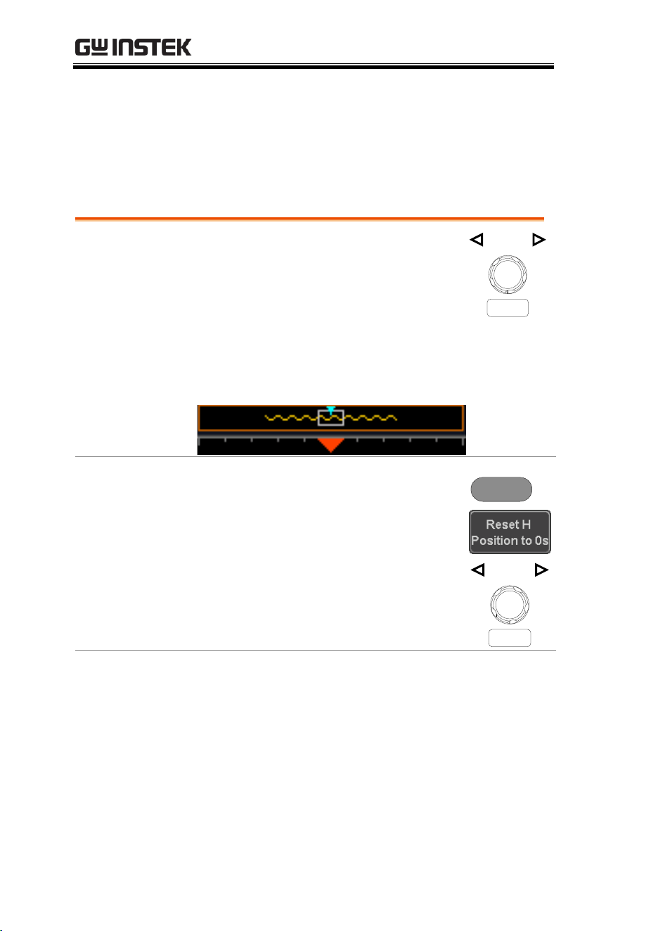
MDO-2000E series User Manual
102
Horizontal View
This section describes how to set the horizontal scale, position, and
waveform display mode.
Move Waveform Position Horizontally
Panel Operation
The horizontal position knob moves
the waveform left/right.
POSITION
PUSH TO
ZERO
As the waveform moves, a position indicator on
the top of the display indicates the horizontal
position of the waveform in memory.
Reset Horizontal
Position
1. To reset the horizontal position,
press the Acquire key and then
press Reset H Position to 0s from the
bottom menu.
Alternatively, pushing the
horizontal position knob will also
reset the position to zero.
Acquire
POSITION
PUSH TO
ZERO
Run Mode
In Run mode, the memory bar keeps its relative
position in the memory since the entire memory is
continuously captured and updated.
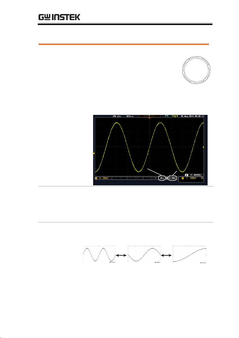
ADVANCED CONFIGURATION
103
Select Horizontal Scale
Select Horizontal
Scale
To select the timebase (time/div), turn
the horizontal Scale knob; left (slow)
or right (fast).
SCALE
Range
1ns/div ~ 100s/div, 1-2-5 increment
The timebase indicator updates as the horizontal
scale is adjusted.
Horizontal
position
Timebase
Run Mode
In Run mode, the memory bar and waveform size
keep their proportion. When the timebase becomes
slower, roll mode is activated (if the trigger is set
to Auto).
Stop Mode
In Stop mode, the waveform size changes
according to the scale.
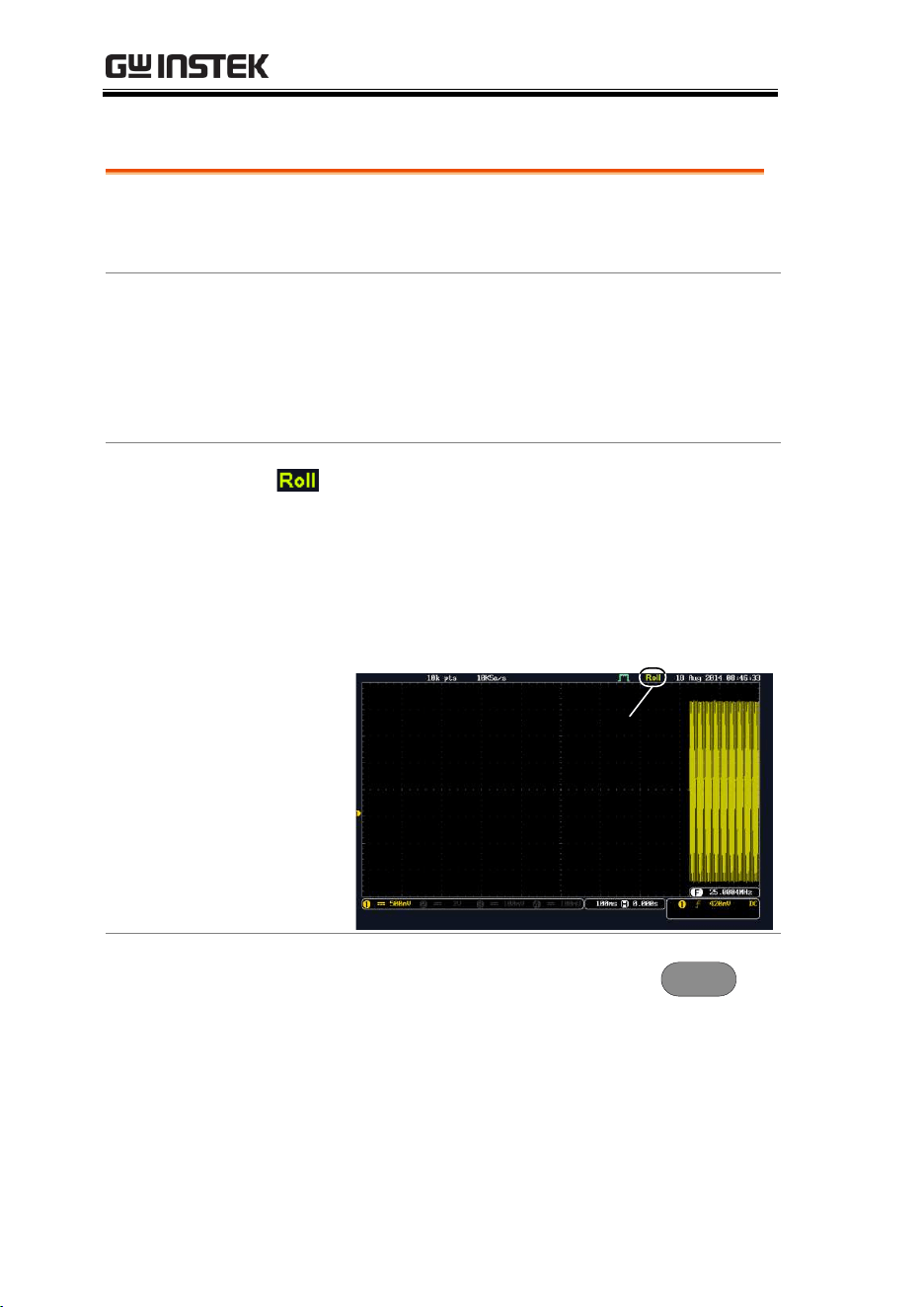
MDO-2000E series User Manual
104
Select Waveform Update Mode
Background
The display update mode is switched
automatically or manually according to the
timebase and trigger.
Normal
Updates the whole displayed waveform at
once. Automatically selected when the
timebase (sampling rate) is fast.
Timebase
≤50ms/div
Trigger
all modes
Roll Mode
Updates and moves the waveform
gradually from the right side of the
display to the left. Automatically selected
when the timebase (sampling rate) is slow.
Timebase
≥100ms/div
Trigger
all modes
Roll mode
Select Update
Mode Manually
1. Press the Trigger Menu key.
Menu
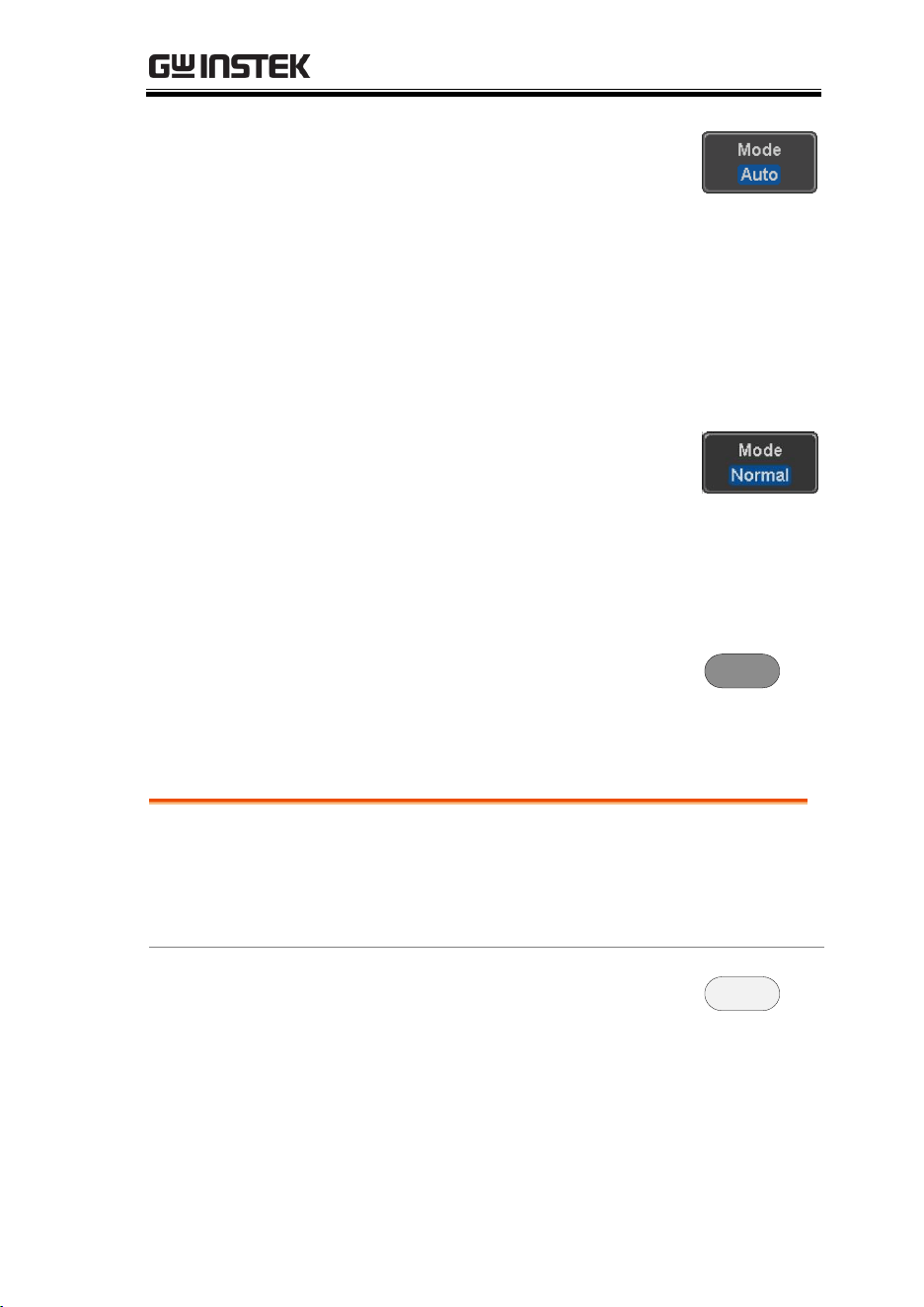
ADVANCED CONFIGURATION
105
2. Press Mode Auto/Normal key from
the bottom menu to let the
equipment choose between Auto
(Untriggered Roll) and Normal
mode.
The auto (Untriggered Roll) trigger
mode enables free-running and roll
mode (timebase >=100ms/div)
acquisitions.
The normal trigger mode enables
the equipment which trigger only
on valid trigger events. If no
trigger occurs, the last waveform
record acquired remains on the
display. If no last waveform exists,
no waveform is displayed
User can also force the equipment
to trigger. To do so, press the Force-
Trig key on the front panel.
Force-Trig
Zoom Waveform Horizontally
Background
When in Zoom mode, the screen is split into 2
sections. The top of the display shows the full
record length, while the bottom of the screen
shows the normal view.
Panel Operation
1. Press the Zoom key.
Zoom
2. The Zoom mode screen appears.
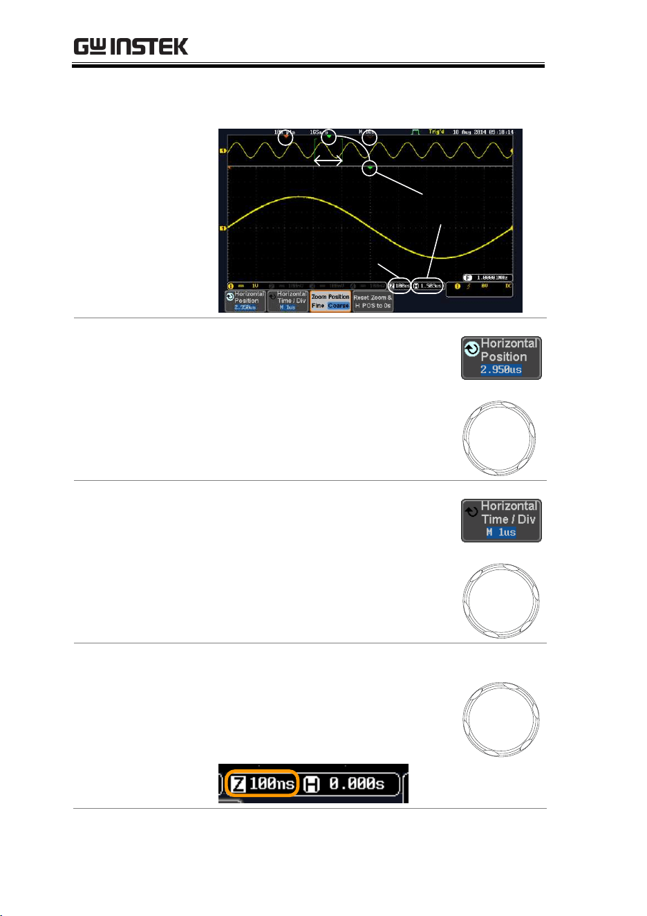
MDO-2000E series User Manual
106
Zoom
timebase
Zoom
position
Zoom
window
Horizontal
position
Trigger
position
Horizontal
Navigation
To scroll the waveform left or right,
press Horizontal Position and use the
Variable Position knob.
The horizontal position will be shown
on the Horizontal Position icon.
VARIABLE
Horizontal Scale
To change the horizontal scale, press
Horizontal Time/Div and use the
Variable Position knob.
The scale will be shown on the
Horizontal Time/Div icon.
VARIABLE
Zoom
To increase the zoom range, use the
horizontal Scale knob.
The zoom time base (Z) at the bottom
of the screen will change accordingly.
SCALE
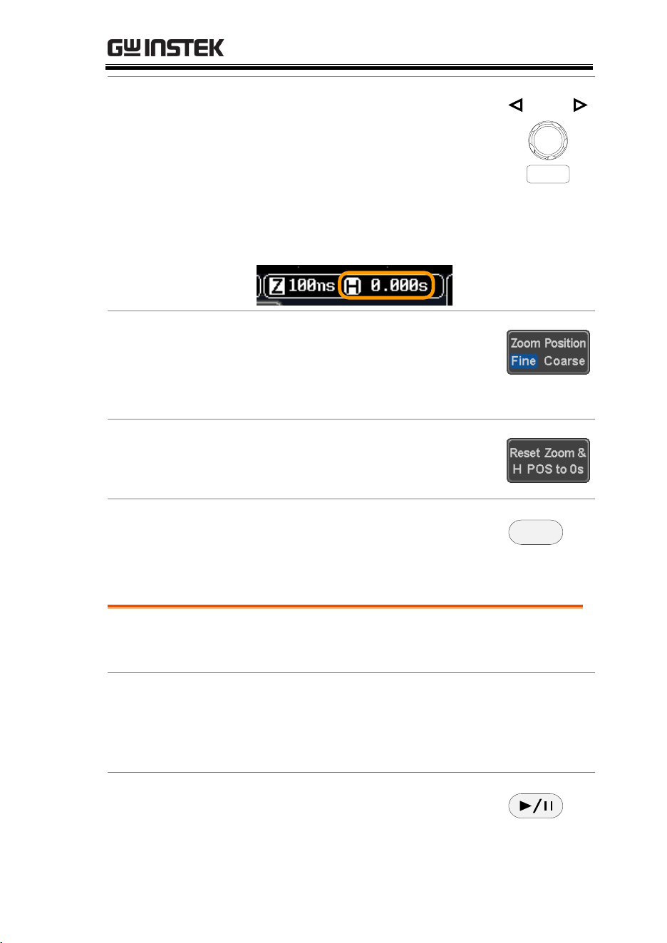
ADVANCED CONFIGURATION
107
Move the Zoom
Window
Use the Horizontal Position knob to pan
the zoom window horizontally.
To reset the zoom position, press the
Horizontal Position knob.
POSITION
PUSH TO
ZERO
The position of the zoom window, relative to the
horizontal position is shown at the bottom of the
screen next to the Zoom timebase.
Scroll Sensitivity
To alter the scrolling sensitivity of the
zoom window, press the Zoom Position
key to toggle the scrolling sensitivity.
Sensitivity
Fine, Coarse
Reset the Zoom
& Horizontal
Position
To reset both the zoom and horizontal
position, press Reset Zoom & H POS to
0s.
Exit
To go back to the original view, press
the Zoom key again.
Zoom
Play/Pause
Background
The Play/Pause key can be used to play through
signals in the Zoom mode.
Note
If the Segmented memory function is turned on,
pressing the play pause key will play through
memory segments. See page 91 for more
information.
Panel Operation
1. Press the Play/Pause menu key.
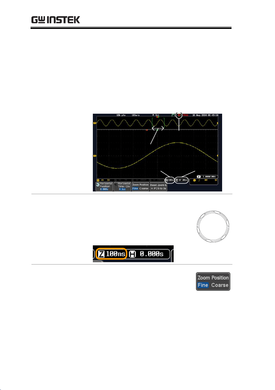
MDO-2000E series User Manual
108
2. The scope will go into the Zoom Play mode and
begin to scroll through the acquisition (from left
to right).
The full-record length waveform will be shown
at the top and the zoomed section will be
shown at the bottom. The Play/Pause indicator
shows the play status.
Zoom
timebase
Zoom
position
Zoom
window
Play/Pause
indicator
Zoom
To increase the zoom range, use the
horizontal Scale knob.
The zoom time base (Z) at the bottom
of the screen will change accordingly.
SCALE
Scroll Speed
To alter the scrolling speed of the
zoom window, press the Zoom Position
key to toggle the scrolling speed.
Sensitivity
Fine, Coarse
Alternatively, use the horizontal position knob
to control the scroll speed.
Turning the Horizontal knob determines the
speed and direction of the scrolling.
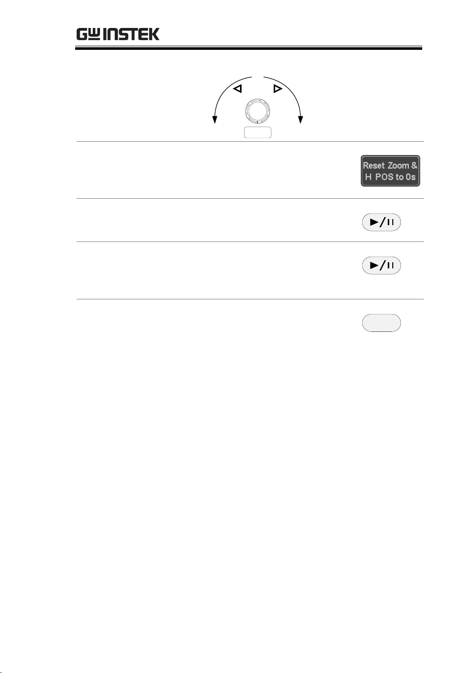
ADVANCED CONFIGURATION
109
Speed
Left
Speed
Right
POSITION
PUSH TO
ZERO
Reset the Zoom
Position
To reset both the zoom position and
horizontal position, press Reset Zoom
& H POS to 0s.
Pause
Press the Play/Pause key to pause or
resume playing the waveform.
Reverse Direction
Press the Play/Pause key when at the
end of the record length to play back
through the waveform in reverse.
Exit
To exit, press the Zoom key.
Zoom
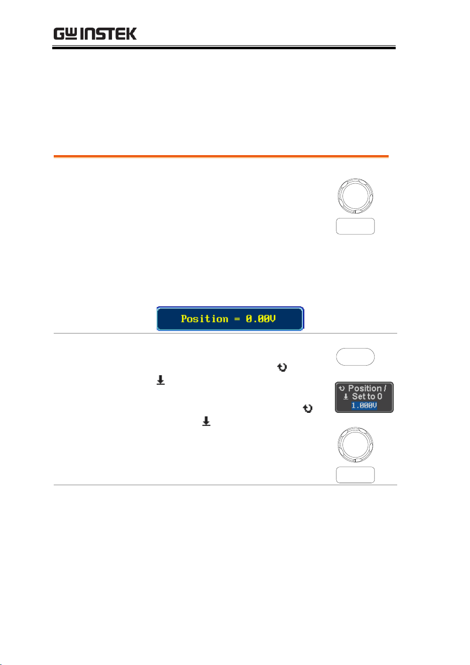
MDO-2000E series User Manual
110
Vertical View (Channel)
This section describes how to set the vertical scale, position, and
coupling mode.
Move Waveform Position Vertically
Panel Operation
1. To move the waveform up or
down, turn the vertical position
knob for each channel.
POSITION
PUSH TO
ZERO
2. As the waveform moves, the vertical position of
the channel indicator appears at the bottom half
of the display.
View or Set the
Vertical Position
3. Press a channel key. The vertical
position is shown in the Position /
Set to 0 soft key.
4. To change the position, press
Position / Set to 0 to reset the
vertical position or turn the vertical
position knob to the desired level.
CH1
POSITION
PUSH TO
ZERO
Run/Stop Mode
The waveform can be moved vertically in both
Run and Stop mode.
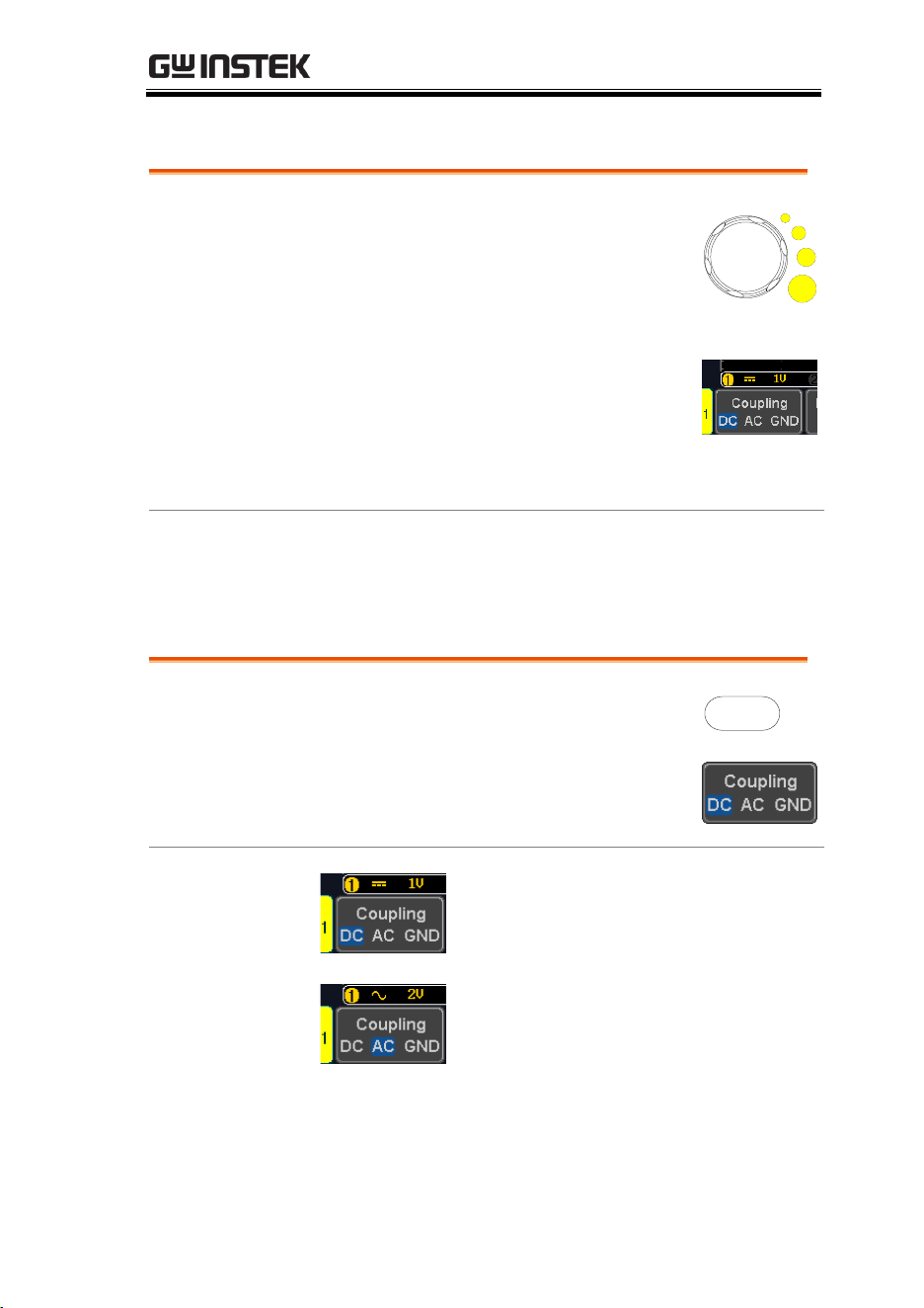
ADVANCED CONFIGURATION
111
Select Vertical Scale
Panel Operation
To change the vertical scale, turn the
vertical SCALE knob; left (down) or
right (up).
SCALE
The vertical scale indicator on the
bottom left of the display changes
accordingly for the specific channel.
Range
1mV/div ~ 10V/div. 1-2-5
increments
Stop Mode
In Stop mode, the vertical scale setting can be
changed.
Select Coupling Mode
Panel Operation
1. Press a channel key.
CH1
2. Press Coupling repeatedly to toggle
the coupling mode for the chosen
channel.
Range
DC coupling mode. The whole
portion (AC and DC) of the signal
appears on the display.
AC coupling mode. Only the AC
portion of the signal appears on the
display. This mode is useful for
observing AC waveforms mixed with
DC signals.
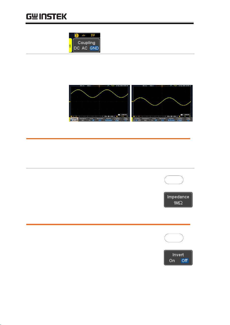
MDO-2000E series User Manual
112
Ground coupling mode. The display
shows only the zero voltage level as a
horizontal line.
Example
Observing the AC portion of the waveform using AC
coupling
DC coupling
AC coupling
Input Impedance
Background
The input impedance of the MDO-2000E Series is
fixed at 1MΩ. The impedance is displayed in the
channel menu.
View Impedance
1. Press the Channel key.
CH1
2. The impedance is displayed in the
bottom menu.
Invert Waveform Vertically
Panel Operation
1. Press the Channel key.
CH1
2. Press Invert to toggle Invert On or
Off.
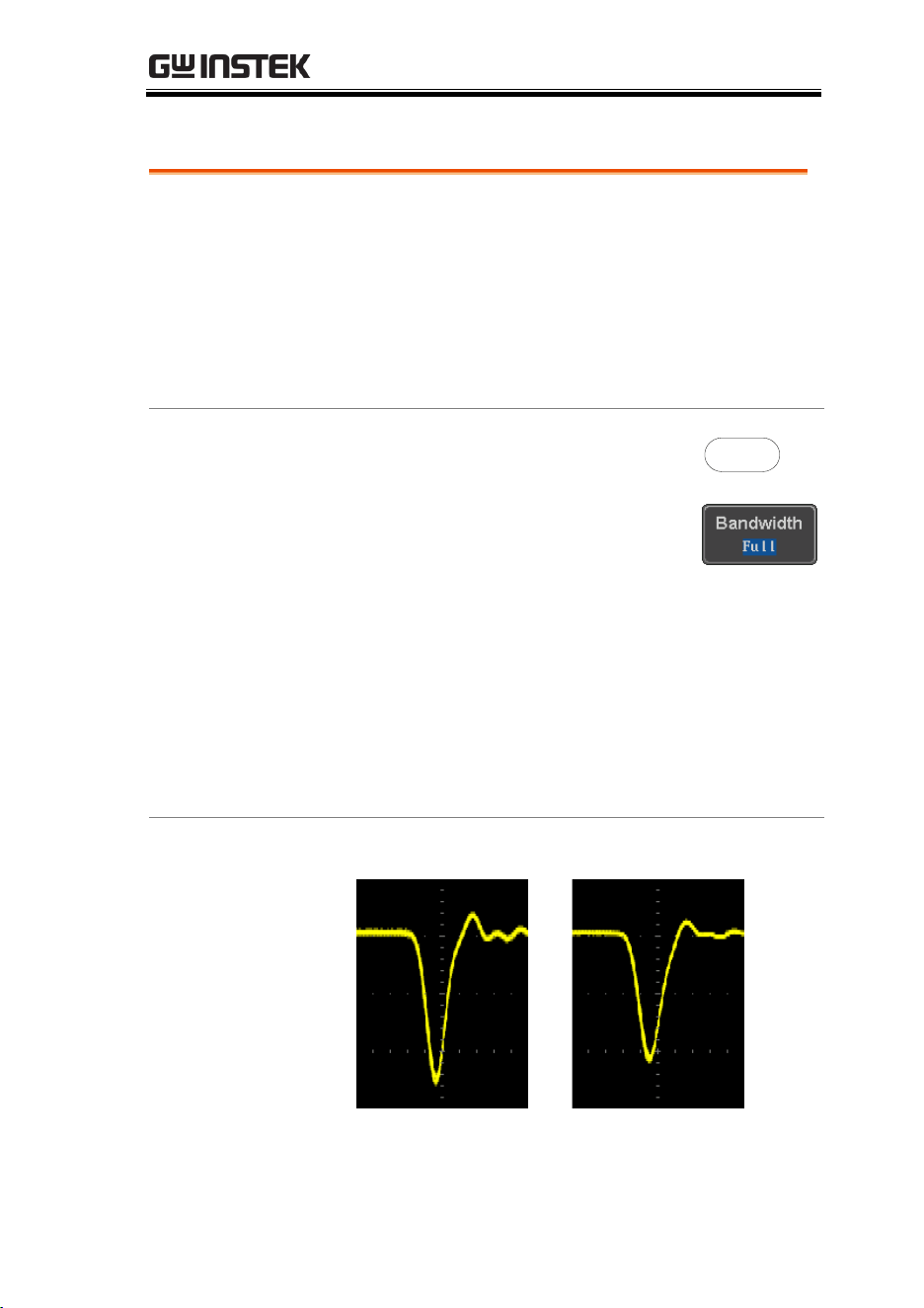
ADVANCED CONFIGURATION
113
Limit Bandwidth
Background
Bandwidth limitation puts the input signal into a
selected bandwidth filter.
This function is useful for cutting out high
frequency noise to see a clear waveform shape.
The bandwidth filters available are dependent on
the bandwidth of the oscilloscope model.
Also refer to the digital filter application, page 291.
Panel Operation
1. Press the Channel key.
CH1
2. Press Bandwidth from the bottom
menu.
3. Choose a bandwidth* from the side menu.
*Depending on the bandwidth of the
oscilloscope.
Range
70MHz models: Full, 20MHz
100MHz models: Full, 20MHz
200MHz models: Full, 20MHz,
100MHz
Example
BW Full
BW Limit 20MHz

MDO-2000E series User Manual
114
Expand by Ground/Center
Background
When the voltage scale is changed, the Expand
function designates whether the signal expands
from the center of the screen or from the signal
ground level. Expand by center can be used to
easily see if a signal has a voltage bias. Expand by
ground is the default setting.
Panel Operation
1. Press a channel key.
CH1
2. Press Expand repeatedly to toggle
between expand By Ground and
Center.
Range
By Ground, By Center
Example
If the vertical scale is changed when the Expand
function is set to ground, the signal will expand
from the ground level*. The ground level does not
change when the vertical scale is changed.
If the vertical scale is changed when the Expand
function is set to center, the signal will expand
from the center of the screen. The ground level will
suit to match the signal position.
*Or from the upper or lower edge of the screen if
the ground level is off-screen.
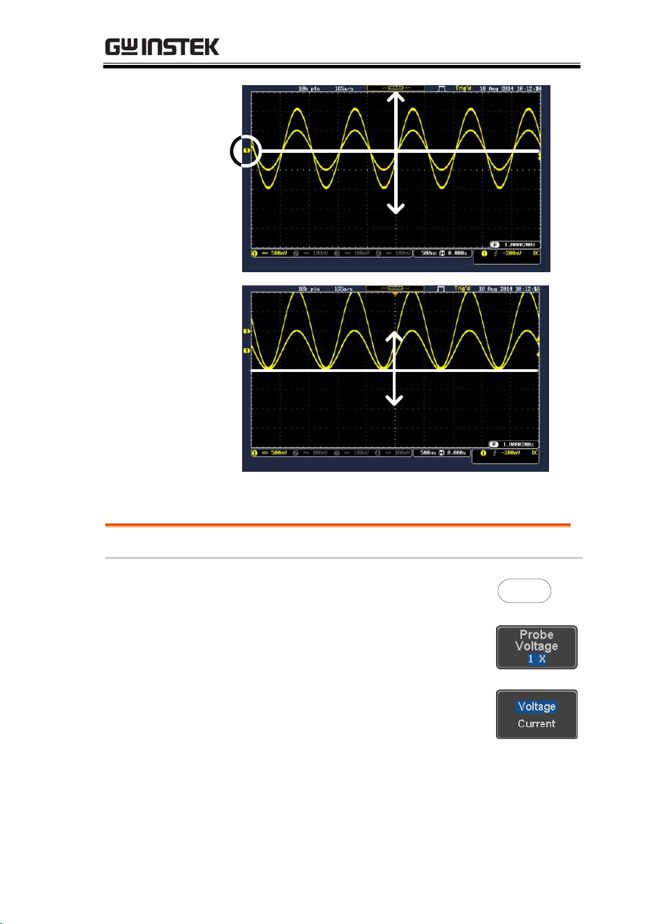
ADVANCED CONFIGURATION
115
Expand by
Ground
Expand by Ground
Expand by Center
Expand by Center
Select Probe Type
Background
A signal probe can be set to voltage or current.
Panel Operation
1. Press the Channel key.
CH1
2. Press Probe from the bottom menu.
3. Press the Voltage/Current soft-key
to toggle between voltage and
current.
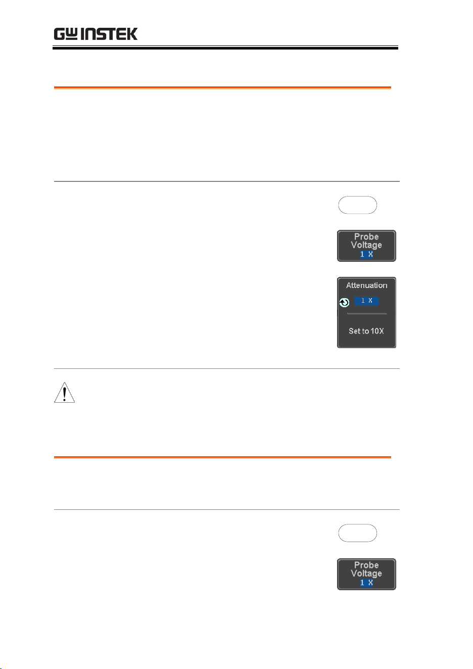
MDO-2000E series User Manual
116
Select Probe Attenuation Level
Background
An oscilloscope probe has an attenuation switch to
lower the original DUT signal level to the
oscilloscope input range, if necessary. The probe
attenuation selection adjusts the vertical scale so
that the voltage level on the display reflects the
real value on a DUT.
Panel Operation
1. Press the Channel key.
CH1
2. Press Probe from the bottom menu.
3. Press Attenuation on the side menu
and use the Variable knob to set
the attenuation.
Alternatively, press Set to 10X.
Range
1mX ~1kX (1-2-5 step)
Note
The attenuation factor adds no influence on the real
signal. It just changes the voltage/current scale on the
display.
Set the Deskew
Background
The deskew function is used to compensate for the
propagation delay between the oscilloscope and
the probe.
Panel Operation
1. Press one of the Channel keys.
CH1
2. Press Probe from the bottom menu.

ADVANCED CONFIGURATION
117
3. Press Deskew on the side menu and
use the Variable knob to set the
deskew time.
Alternatively, press Set to 0s to
reset the deskew time.
Range
-50ns~50ns, 10ps increments
4. Repeat the procedure for another channel if
necessary.
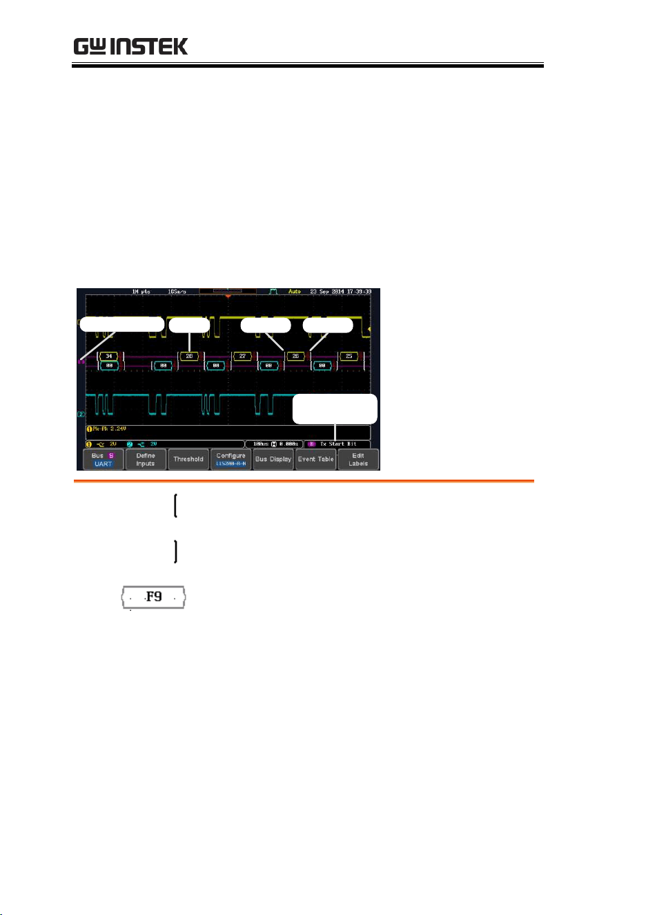
MDO-2000E series User Manual
118
Bus Key Configuration
The Bus key is used to configure the Serial bus inputs and parallel
bus inputs. The bus inputs can be either analog or digital. The Bus
menu also features event tables to track and save your bus data.
The Bus key is used in conjunction with the Bus trigger (page 166)
to decode serial or parallel bus signals.
Bus Display
Bus indicator
Trigger
configuration
Data Start bit Stop bit
Start Bit/Start
of Frame
The Start bit is shown as an open bracket (Serial
bus data only).
Stop Bit/End
of Frame
The Stop bit is shown as a closed bracket (Serial
bus data only).
Data
Data packets/frames/words can be shown in Hex
or Binary. The color of the bus data indicates the
type of data or the channel the data is coming
from, depending on the bus type.
UART:
Color of packet = Color of source
channel.
I
2
C:
Color packet = SDA source channel.
SPI:
Color of packet = MOSI or MISO source
channel.

ADVANCED CONFIGURATION
119
CAN:
Purple = Error frame, Data length control
(DLC), Overload.
Yellow = Identifier.
Cyan = Data.
Orange = CRC.
Red = Bit stuffing error
Parallel
All read words are shown in purple (no
clock) or white (a clock is defined among
the channels).
LIN:
Purple = Break, Sync and Checksum
errors, Wakeup
Yellow = Identifier, Parity
Cyan = Data
Red = Error type
Error
Indicator/
Missing Ack
If there is an error/missing acknowledgement in
decoding the data, a red error indicator will be
shown.
Bus Indicator
The Bus indicator shows the bus position. The
active bus is shown with a solid color. The Variable
knob can be used to horizontally position the Bus
indicator when it is active.
Active bus
(solid indicator)
Activated bus
(transparent indicator)
Trigger
Configuration
Shows the bus trigger (B) and the Trigger On
settings. Please see page 166.
Serial Bus Overview
The Serial Bus includes support for 6 common serial interfaces
UART, I
2
C, SPI, Parallel, CAN and LIN. Each interface is fully
configurable to accommodate variations in the basic protocols.
Each input can be displayed as binary, hexadecimal or ASCII. An
event table can also be created to aid in debugging.

MDO-2000E series User Manual
120
UART
Universal Asynchronous Receiver Transmitter.
The UART bus is able to accommodate a wide
range of various common UART serial
communications.
The UART serial bus software is suitable for a
number of RS-232 protocol variants.
Inputs
Tx, Rx
Threshold
Tx, Rx
Configuration
Baud rate, Parity, Packets, End of
packets, Input polarity
Trigger On
Tx Start Bit, Rx Start Bit, Tx End of
Packet, Rx End of Packet, Tx Data,
Rx Data, Tx Parity Error, Rx Parity
Error
I
2
C
Inter Integrated Circuit is a two line serial data
interface with a serial data line (SDA) and serial
clock line (SCLK). The R/W bit can be configured.
Inputs
SCLK, SDA
Threshold
SCLK, SDA
Configuration
Addressing mode, Read/Write in
address
Trigger On
Start, Repeat Start, Stop, Missing
Ack, Address, Data, Address/Data
SPI
The SPI (Serial Interface Peripheral) bus is fully
configurable to accommodate the wide variety of
SPI interfaces. This bus is only available on 4
channel models.
Inputs
SCLK, SS, MOSI, MISO
Threshold
SCLK, SS, MOSI, MISO
Configuration
SCLK edge, SS logic level, Word
size, Bit order

ADVANCED CONFIGURATION
121
Trigger On
SS Active, MOSI, MISO,
MOSI&MISO
CAN
The CAN (Controller Area Network) bus is a 2-
wire, message-based protocol.
Inputs
CAN Input
Threshold
CAN Input
Configuration
Signal Type, Bit Rate
Trigger On
Start of Frame, Type of Frame,
Identifier, Data, Id & Data, End of
Frame, Missing Ack, Bit Stuffing
Err.
LIN
The LIN (Local Interconnect Network) bus is used
to decode a wide range of common LIN
configurations.
Inputs
LIN Input
Threshold
LIN Input
Configuration
Bit Rate, LIN Standard, Include
Parity Bits with Id
Trigger On
Sync, Identifier, Data, Id & Data,
Wakeup Frame, Sleep Frame, Error

MDO-2000E series User Manual
122
UART Serial Bus Configuration
The UART bus menu is designed to decode RS-232 and other
common RS-232 variants such as RS-422, RS-485. The software
configuration is also flexible enough to decode the many
proprietary protocols based on RS-232.
Background
Basic RS-232 protocol uses single-ended data
transmissions. The signal voltage levels can be
high (±15V) and employ active low signaling.
High speed variants of RS-232, such as RS-422 and
RS-485 use differential signaling and commonly
employ low voltage differential signals with active
high signaling.
Universal Asynchronous Receiver/Transmitter
(UART) or RS-232 driver/receiver ICs commonly
used for embedded applications typically use
active high signaling with standard IC signal
levels.
Operation
1. Connect each of the bus signals (Tx, Rx) to one
of the oscilloscope’s analog or digital channels.
Connect the ground potential of the bus to one
of the probes’ ground clip if you are using the
analog channels or to the ground connector of
the Digital card if you are using the digital
channels.
Tx
GND
Rx
X
10
X
1
G
1
2
X
10
X
1
Analog
Digital
ADVANCED CONFIGURATION
123
2. Press the BUS key.
BUS
B
3. Press Bus from the bottom menu
and choose the UART serial bus on
the side menu.
4. Press either Analog Source or Digital
Source to choose whether the
sources for the UART bus are
analog or digital.
Define Inputs
5. Press Define Inputs from the bottom
menu.
6. From the side menu choose the Tx
Input and the Rx
Input source and the signal
polarity.
Tx
OFF, CH1~CH4 or OFF, D0~D15 *
Rx
OFF, CH1~CH4 or OFF, D0~D15 *
Polarity
Normal (High = 0), Inverted (High = 1)
*Depending on your choice at step 4 above.
Configuration
The Configure key sets the baud rate, number of data
bits and parity.
7. Press Configure from the bottom
menu.
8. From the side menu select the Baud rate, Data
bits, Parity, Packets and End of Packet bits.

MDO-2000E series User Manual
124
Baud Rate
50, 75, 110, 134, 150, 300, 600, 1200,
1800, 2000, 2400, 3600, 4800, 7200,
9600, 14400, 15200, 19200, 28800,
31250, 38400, 56000, 57600, 76800,
115200, 128000, 230400, 460800,
921600, 1382400, 1843200, 2764800
Data Bits
8 (fixed)
Parity
Odd, Even, None
Packets
On, Off
End of
Packet
(Hex)
00(NUL), OA(LF), OD(CR), 20(SP),
FF
I
2
C Serial Bus Interface
The I
2
C bus is a 2 wire interface with a serial data line (SDA) and
serial clock line (SCLK). The I
2
C protocol supports 7 or 10 bit
addressing and multiple masters. The scope will trigger on any of
the following conditions: a start/stop condition, a restart, a missing
acknowledge message, Address, Data or Address & Data frames.
The I
2
C trigger can be configured for 7 or 10 bit addressing with the
option to ignore the R/W bit as well as triggering on a data value
or a specific address and direction (read or write or both).
Panel operation
1. Connect each of the bus signals (SCLK, SDA) to
one of the oscilloscope’s analog or digital
channels. Connect the ground potential to one
of the probes’ ground clip if you are using the
analog channels or to the ground connector of
the Digital card if you are using the digital
channels.
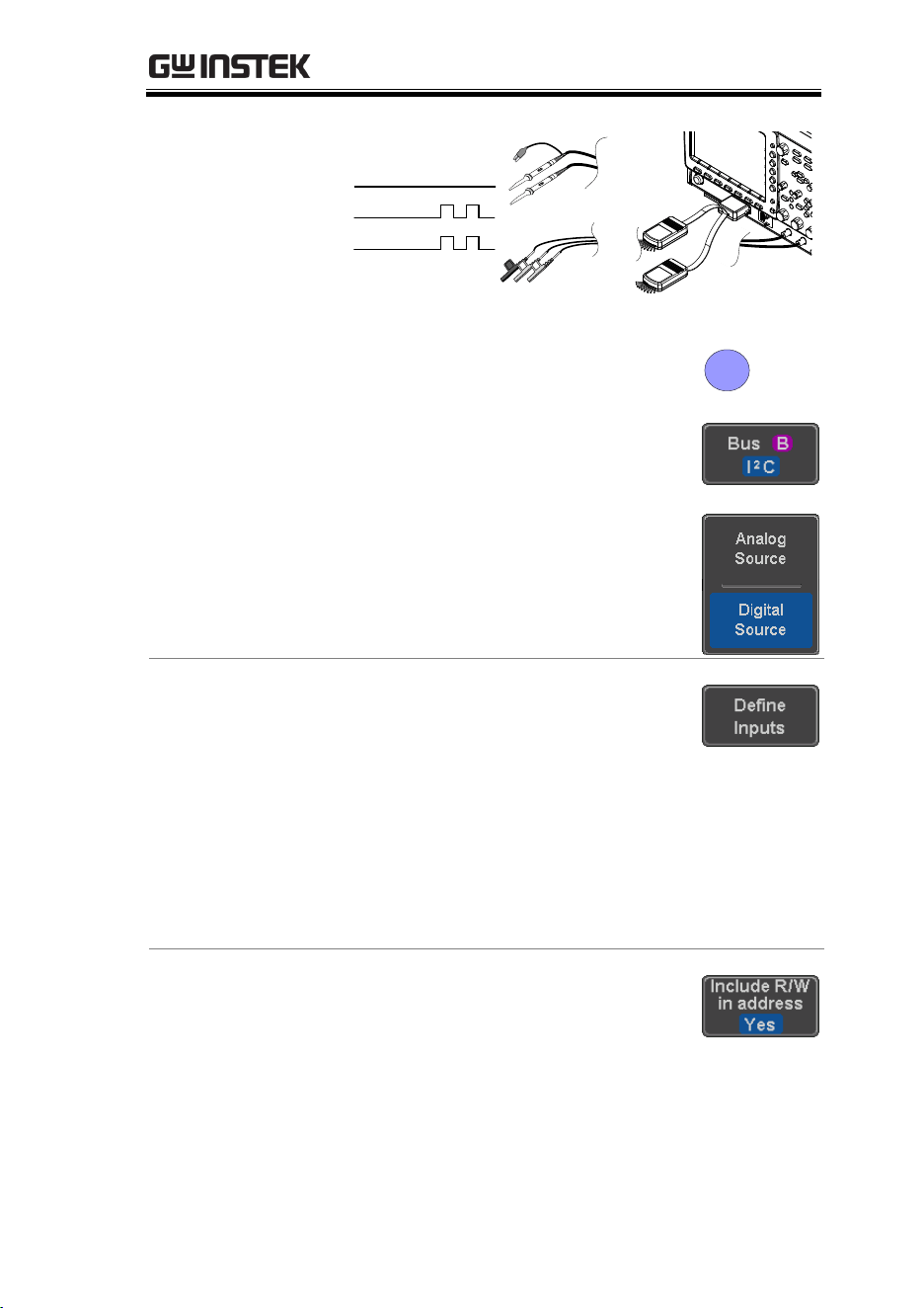
ADVANCED CONFIGURATION
125
SDA
GND
SCLK
X
10
X
1
G
1
2
X
10
X
1
Analog
Digital
2. Press the Bus key.
BUS
B
3. Press Bus from the bottom menu
and choose I
2
C from the side menu.
4. Press either Analog Source or Digital
Source to choose whether the
sources for the I
2
C bus are analog
or digital.
Define Inputs
5. Press Define Inputs from the bottom
menu.
6. From the side menu choose the
SCLK input and the SDA Input.
SCLK
CH1~CH4 or D0~D15 *
SDA
CH1~CH4 or D0~D15 *
*Depending on your choice at step 4 above.
Include R/W in
address
To configure whether you want the
R/W bit to be included in the
address, press Include R/W in
address and set to Yes or No in the
side menu.
R/W Bit
Yes, No
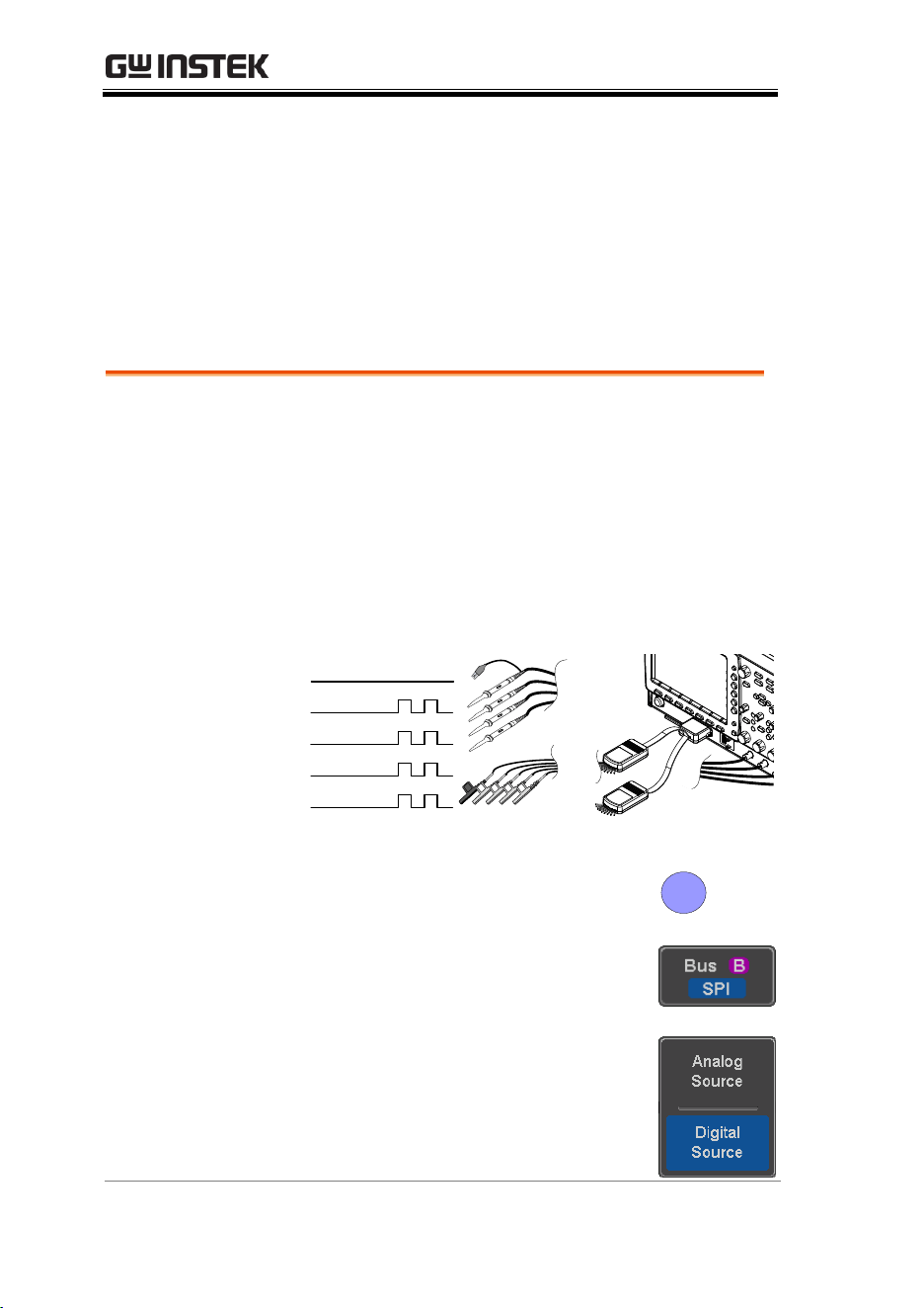
MDO-2000E series User Manual
126
SPI Serial Bus Interface
The serial peripheral interface (SPI) is a full duplex 4 wire
synchronous serial interface. The 4 signals lines: Serial clock line
(SCLK), slave select (SS), Master output/slave input (MOSI, or
SIMO) and the Master input/slave output (MISO, or SOMI). The
word size is configurable from 4 to 32 bits. The SPI triggers on the
data pattern at the start of each framing period. Note: The SPI bus
with analog source is only available for 4 channel models.
Panel operation
1. Connect each of the bus signals (SCLK, SS,
MOSI, MISO) to the oscilloscope’s 4 analog
channels or to one of the digital channels.
Connect the ground potential to one of the
probes’ ground clip if you are using the analog
channels or to the ground connector of the
Digital card if you are using the digital
channels.
SS
MOSI
MISO
GND
SCLK
X
10
X
1
G
1
2
3
4
X
10
X
1
X
10
X
1
X
10
X
1
Analog
Digital
2. Press the Bus key.
BUS
B
3. Press Bus from the bottom menu
and choose the SPI serial bus.
4. Press either Analog Source or Digital
Source to choose whether the
sources for the SPI bus are analog
or digital.
ADVANCED CONFIGURATION
127
Define Inputs
5. Press Define Inputs from the lower
menu.
6. From the side menu choose the
SCLK, SS, MOSI and MISO inputs.
SCLK
CH1~CH4 or D0~D15 *
SS
CH1~CH4 or D0~D15 *
MOSI
OFF, CH1~CH4 or OFF, D0~D15 *
MISO
OFF, CH1~CH4 or OFF, D0~D15 *
*Depending on your choice at step 4 above.
Configuration
The Configure menu sets the data line logic level,
SCLK edge polarity, word size and bit order.
7. Press Configure from the bottom
menu.
8. From the side menu select SCLK edge, SS logic
level, word Size and Bit order.
SCLK
rising edge , falling edge
SS
Active High, Active Low
Word Size
4 ~ 32 bits
Bit Order
MS First, LS First
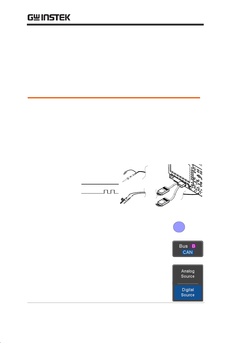
MDO-2000E series User Manual
128
CAN Serial Bus Interface
The controller area network (CAN) bus is a half duplex 2 wire
synchronous serial interface. The CAN bus is a multi-master
communication system that relies on arbitration to solve contention
issues. The MDO-2000E series supports both CAN 2.0A and 2.0B.
The CAN bus uses two wires, CAN-High and CAN-Low. These
wires are voltage inverted, and as such, the MDO-2000E Series only
needs one wire, CAN-High or CAN-Low for decoding.
Panel operation
1. Connect the bus signal (CAN Input) to one of
the oscilloscope’s analog or digital channels.
Connect the ground potential to one of the
probes’ ground clip if you are using the analog
channels or to the ground connector of the
Digital card if you are using the digital
channels.
CAN input
GND
G
1
X
10
X
1
Analog
Digital
2. Press the Bus key.
BUS
B
3. Press Bus from the bottom menu
and choose the CAN serial bus.
4. Press either Analog Source or Digital
Source to choose whether the
source for the CAN bus is analog
or digital.
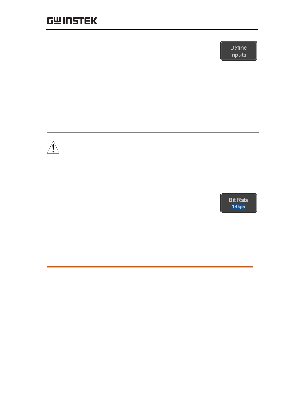
ADVANCED CONFIGURATION
129
Define Inputs
5. Press Define Inputs from the lower
menu.
6. From the side menu choose the
CAN Input inputs and the signal
type.
CAN Input
CH1~CH4 or D0~D15 *
Signal Type
CAN_H, CAN_L, Tx, Rx.
*Depending on your choice at step 4 above.
Note
The Sample Point soft-key indicates the sampling
position of each bit. This parameter is fixed.
Bit Rate
The Bit Rate menu sets the bit rate of the bus. The
bit rate is usually tied to the bus length.
7. Press Bit Rate from the bottom
menu and set the bit rate.
Bit Rate
10kbps, 20kbps, 50kbps, 125kbps,
250kbps, 500kbps, 800kbps, 1Mbps
LIN Serial Bus Interface
The local interconnect network (LIN) bus is a single wire interface.
Panel operation
1. Connect the bus signal (LIN Input) to one of the
oscilloscope’s analog or digital channels.
Connect the ground potential to one of the
probes’ ground clip if you are using the analog
channels or to the ground connector of the
Digital card if you are the using digital
channels.
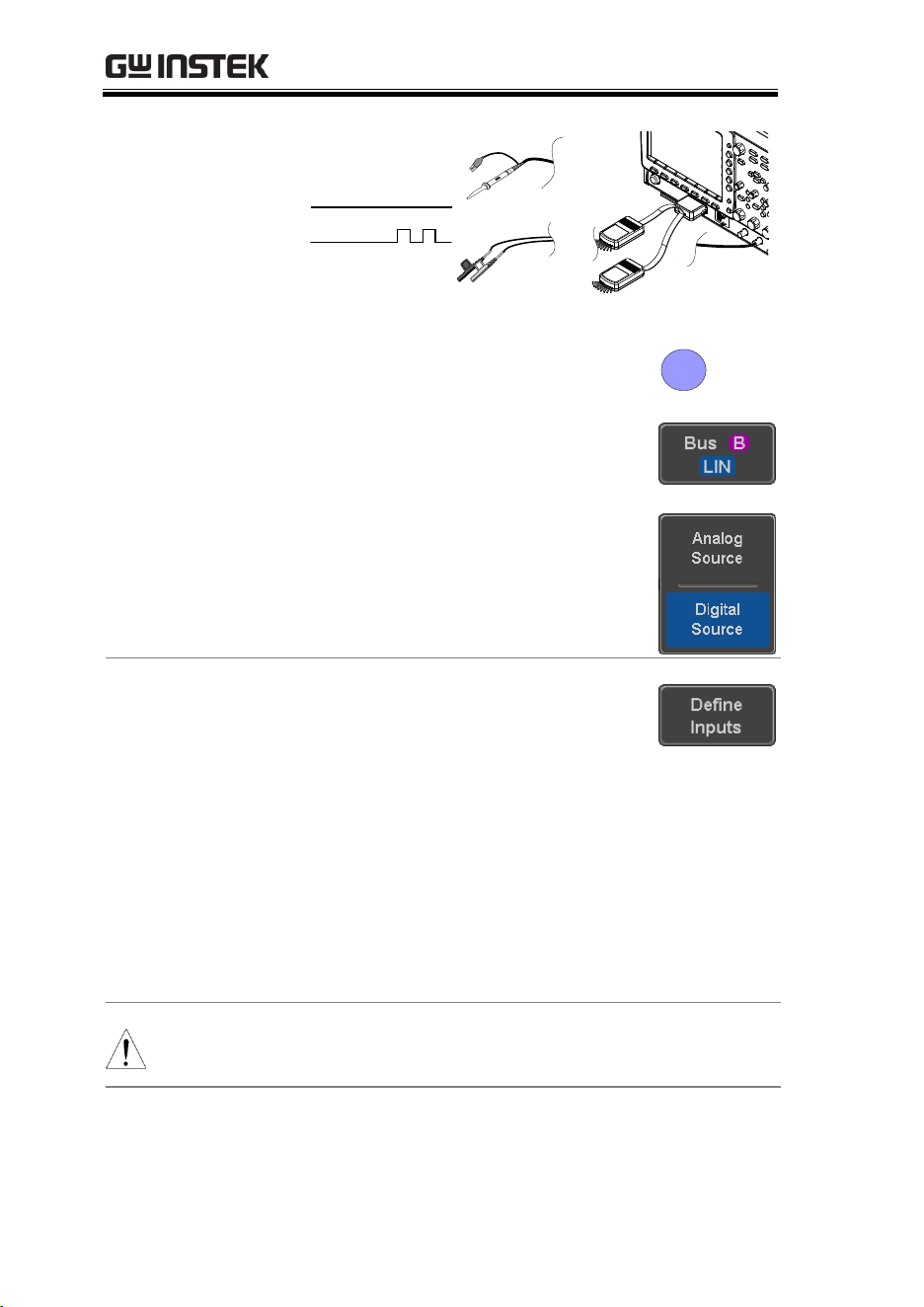
MDO-2000E series User Manual
130
LIN input
GND
G
1
X
10
X
1
Analog
Digital
2. Press the Bus key.
BUS
B
3. Press Bus from the bottom menu
and choose the LIN serial bus.
4. Press either Analog Source or Digital
Source to choose whether the
source for the LIN bus is analog or
digital.
Define Inputs
5. Press Define Inputs from the lower
menu.
6. From the side menu choose the
LIN input and the polarity of the
bus.
LIN Input
CH1~CH4 or D0~D15 *
Polarity
Normal (High = 1),
Inverted(High = 0)
*Depending on your choice at step 4 above.
Note
The Sample Point soft-key indicates the sampling
position of each bit. This parameter is fixed.
Configuration
The Configure menu sets the bit rate, the LIN
standard and the parity options for the Id frame.
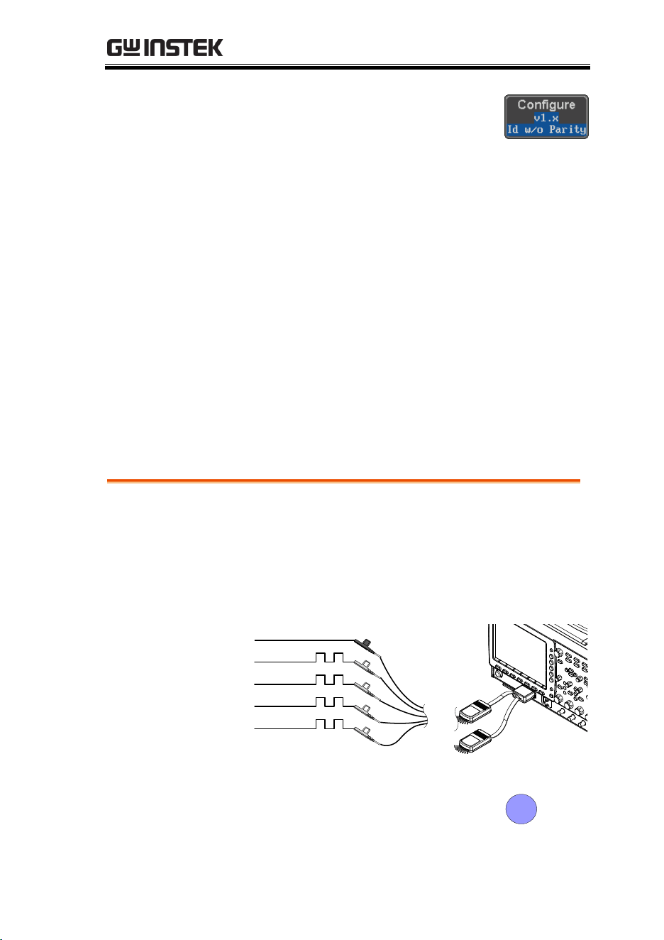
ADVANCED CONFIGURATION
131
7. Press Configure from the bottom
menu.
8. From the side menu select configuration items.
Bit Rate
1.2kbps, 2.4kbps, 4.8kbps,
9.6kbps, 10.417kbps, 19.2kbps
LIN Standard
V1.x, V2.x, Both
Include Parity
Bits with Id
On, Off
Parallel Bus
The digital channels can be configured as a parallel bus. The
number of bits that defines the bus as well as which bit is used as
the bus clock can also be configured. The trigger should also be set
to parallel bus. Please see page 177.
The read data can be displayed as binary, hexadecimal or ASCII.
An event table can also be created to aid in debugging.
Panel operation
1. Connect each of the parallel bus signals
(variable length can be configured) to the
oscilloscope’s digital channels. Connect the
ground potential to the ground connector of the
Digital card.
bit2
bit3
bit4
GND
bit1
G
1
2
3
4
Digital
2. Press the Bus key.
BUS
B
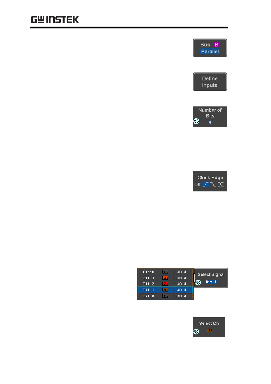
MDO-2000E series User Manual
132
3. Press the Bus soft-key and select
Parallel from the side menu.
4. Press Define Inputs from the bottom
menu.
5. Press Number of Bits from the side
menu and select the number of bits
for the data bus.
By default the bus will assign bit 0
to D0, bit 1 to D1, and so on up to
the last bit.
6. You may also assign a bit as a
clock. This bit will be one of the
bits in the bus. To add a clock bit,
press Clock Edge and select type of
clock edge. Selecting Off will
disable the clock bit.
7. If you wish to define which channels are
assigned to the bus, press Select Signal from the
side menu and select the bit that you wish to
assign.
Channel 1 is
currently
assigned to bit 1.
8. Next, press Select Ch and select
which channel is assigned to the
bit selected above.
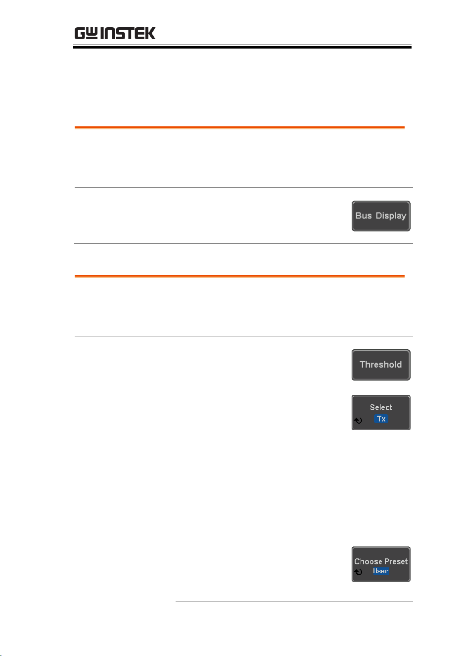
ADVANCED CONFIGURATION
133
9. Repeat steps 7 and 8 for any remaining bits and
for the clock, if enabled.
Bus Encoding
Background
The bus that is displayed on the screen or in the
event tables can be set to either hex or binary
formats.
Operation
Press Bus Display from the Bus
menu and choose either Hex or
Binary from the side menu.
Threshold configuration
Background
The threshold levels for the Serial buses can be set
to either a user-defined threshold level or to pre-
set threshold.
Set the Threshold
1. Press Threshold from the bottom
menu.
2. Press Select from the side menu to
choose one of the lines that are
configured for your type of bus.
UART
Tx, Rx
I
2
C
SCLK, SDA
SPI
SCLK, SS, MOSI, MOSI
CAN
CAN_H, CAN_L, Tx, Rx
LIN
LIN Input
3. Press Choose Preset to select a pre-
set logic threshold.
Logic Type
Threshold

MDO-2000E series User Manual
134
TTL
1.4V
5.0V CMOS
2.5V
3.3V CMOS
1.65V
2.5V CMOS
1.25V
ECL
-1.3V
PECL
3.7V
0V
0V
4. Press Threshold to set a user
defined threshold for the currently
selected input.
For the analog channels, the
threshold level depends on the
vertical scale :
Scale
Range
Scale
Range
10V/Div
±290V
50mV/Div
±5.2V
5V/Div
±270V
20mV/Div
±580mV
2V/Div
±33V
10mV/Div
±540mV
1V/Div
±29V
5mV/Div
±520mV
500mV/Div
±27V
2mV/Div
±508mV
200mV/Div
±5.8V
1mV/Div
±504mV
100mV/Div
±5.4V
For the digital channels, only the following
range can be chosen:
Range
±5V
Note
Setting the threshold levels of digital channels
from the Bus menu will also change the threshold
levels set in the Logic Analyzer menu (page 207).
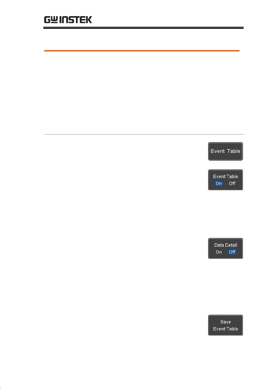
ADVANCED CONFIGURATION
135
Serial Bus Event Tables
Background
The serial bus event tables list when each data
event on the bus occurred. The data is displayed as
either hex or binary, depending on the bus display
settings.
Event tables can be saved to disk in a CSV format.
The files will be named “Event_TableXXXX.CSV”,
where XXXX is a number from 0000 to 9999. See
page 138 for details.
Operation
1. Press Event Table from the bottom
menu.
2. Press Event Table from the side
menu to turn the event table on or
off.
Event
On, Off
Use the Variable knob to scroll through the
event table.
Data Detail
(I
2
C only)
3. To view the data at a particular
address in more detail, turn Data
Detail On. This is only available for
the I
2
C bus.
Detail
On, Off
Use the Variable knob to scroll through the
Data Detail event table.
Save Event Table
4. To save the event table, press Save
Event Table. The Event table will be
saved to the current file path in a
CSV format. See page 138 for
details.
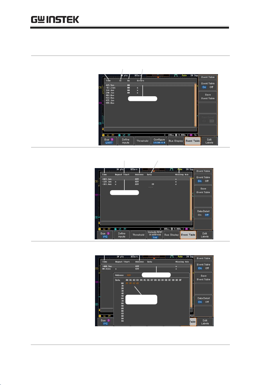
MDO-2000E series User Manual
136
Use the variable knob to scroll through the
event table.
Example:
UART Event table
Time of trigger
Tx
Rx
Errors
Select cursor
Example:
I
2
C Event table
Time of trigger
Repeat Start
Address
Data at address
Missing Ack
Select cursor
Example:
I
2
C Data Detail
Time of trigger Address
Data at cursor
position
Select cursor
Note
Data Detail is only available with the I
2
C bus.
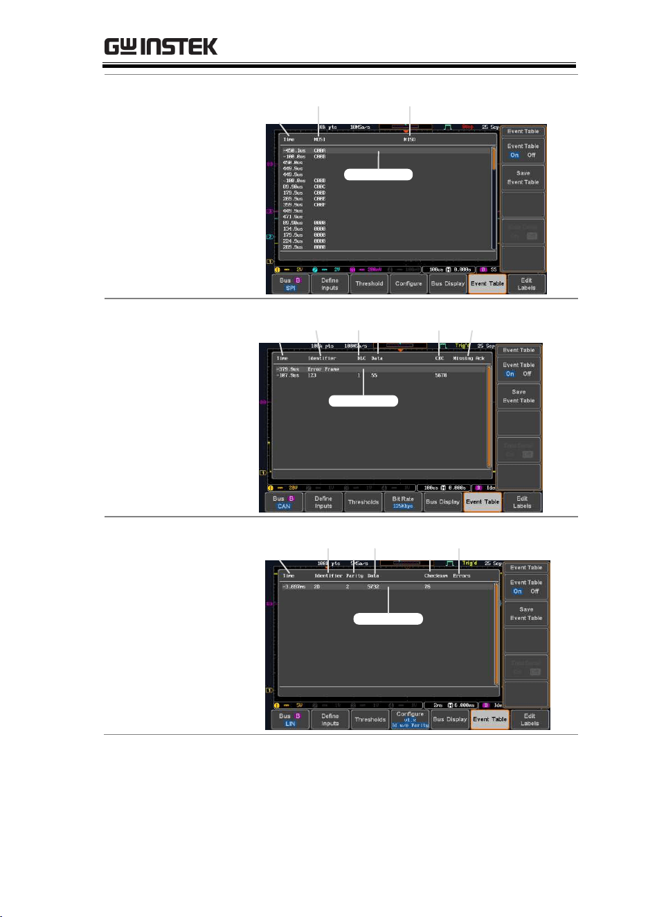
ADVANCED CONFIGURATION
137
Example:
SPI Event table
Time of trigger
MOSI MISO
Select cursor
Example:
CAN Event table
Time of trigger
DLC
Data
CRC Missing ACK
Select cursor
Identifier
Example:
LIN Event table
Time of trigger
Identifier
Checksum
Errors
Select cursor
Parity
Data
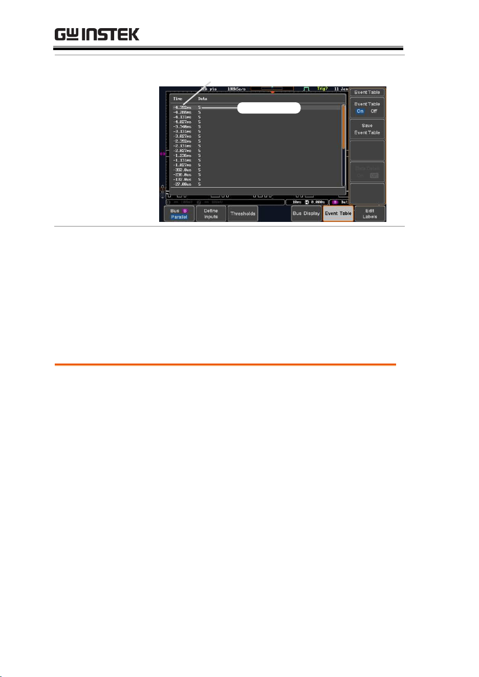
MDO-2000E series User Manual
138
Example:
Parallel Bus Event
table
Time of event
Event data
Event Tables Format
Each bus type (UART, I
2
C, SPI, CAN and LIN) can have an event
table saved containing each bus event as a .CSV file. An event is
defined as a packet/frame/word or associated set of data being
successfully read according to the specific operating conditions of
each bus (Start of frame, acknowledgements, checksums, etc …).
The data associated with each event and the time of each event is
recorded.
File Type
Each event table is saved as
Event_TableXXXX.CSV into the designated file
path. Each event table is numbered sequentially
from 0000 to 9999. For example the first event table
will be saved as Event_Table0000.CSV, the second
as Event_Table0001.CSV, and so on.
Event Table Data
Each event table saves a timestamp of each event
relative to the trigger as well as the data in each
frame/packet at the time of an event. The
frame/packet data is saved in HEX format.
The table below lists in order the data saved for
each event table.
UART
Time, Tx frame data, Rx frame data,
Errors.

ADVANCED CONFIGURATION
139
I
2
C
Time, Repeat Start, Address, Data,
Missing Ack.
SPI
Time, MISO frame data, MOSI
frame data.
CAN
Time, Identifier, DLC, Data, CRC,
Missing Ack.
Parallel
Time, Data.
LIN
Time, Identifier, Parity, Data,
Checksum, Errors.
Example
Below shows the data associated with an SPI event
table in a spreadsheet.
Adding a Label to a Bus
Background
A Label can be added to the buses. This label will
appear next to the bus indicator on the left hand-
side of the display.
Panel Operation
1. To add a label to the bus, press Edit
Labels from the Bus menu.
2. To choose a preset label, Press User
Preset from the side menu and
choose a label.
Labels
ACK, AD0, ADDR, ANALOG,
BIT, CAS, CLK, CLOCK, CLR,
COUNT, DATA, DTACK,
ENABLE, HALT, INT, IN, IRQ,
LATCH, LOAD, NMI
Time MOSI MISO
-11.60us 0D87 0D87
-10.16us 06C0 06C0
-8.720us 8343 343
-7.282us 243 243
-5.840us 0C88 0C88
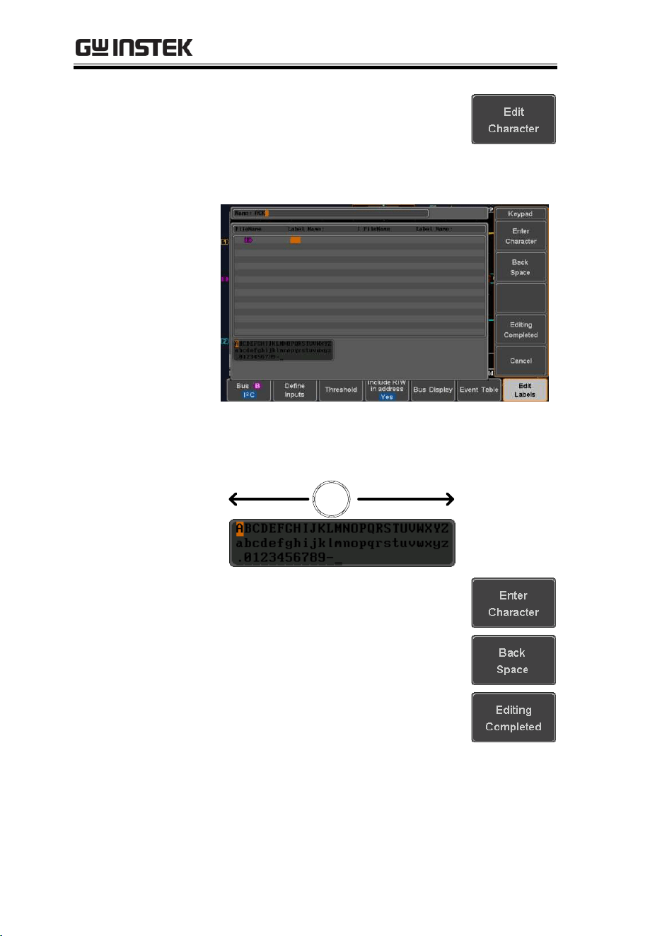
MDO-2000E series User Manual
140
Edit Label
3. Press Edit Character to edit the
current label.
4. The Edit Label window appears.
5. Use the Variable knob to highlight
a character.
VARIABLE
Press Enter Character to select a
number or letter.
Press Back Space to delete a
character.
Press Editing Completed to create
the new label and return to the
previous menu.
Note: this key must be pressed to
save the label, even for the preset
labels.
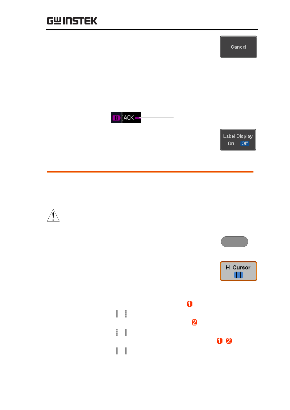
ADVANCED CONFIGURATION
141
Press Cancel to cancel the editing
and return to the Edit Label menu.
6. The label will appear next to the bus indicator.
Below, the label “ACK” was created for the
bus.
The bus is labeled
as ACK
Remove Label
Press Label Display to toggle the label
on or off.
Using Cursors with the Serial Bus or Parallel Bus
Background
The cursors can be used to read bus values at any
position.
Note
Ensure that one of the serial buses has been
selected and is activated.
Panel Operation
1. Press the Cursor key. Horizontal
cursors appear on the display.
Cursor
2. Press the H Cursor soft-key and
select which cursor(s) you wish to
position.
Range
Description
Left cursor ( ) movable, right
cursor position fixed
Right cursor ( ) movable, left
cursor position fixed
Left and right cursor ( + )
movable together

MDO-2000E series User Manual
142
3. The cursor position information appears on the
top left hand side of the screen.
Example: I
2
C cursors.
Cursor
Hor. position, Bus value(s)
Cursor
Hor. position, Bus value(s)
4. Use the Variable knob to move the
movable cursor(s) left or right.
VARIABLE
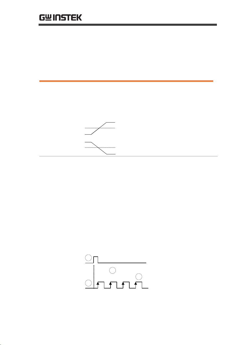
ADVANCED CONFIGURATION
143
Trigger
The trigger configures the conditions for when the MDO-2000E
SERIES captures a waveform.
Trigger Type Overview
Edge
The edge trigger is the simplest trigger type. An
edge trigger triggers when the signal crosses an
amplitude threshold with either a positive or
negative slope.
Rising edge trigger
Falling edge trigger
Delay
The Delay trigger works in tandem with the edge
trigger, by waiting for a specified time (duration)
or number of events before the delay trigger starts.
This method allows pinpointing a location in a
long series of trigger events.
Note: when using the delay trigger, the edge trigger
source can be any one of the channel inputs, the EXT*
input or the AC line.
*EXT is only available on 2 channel models.
Delay trigger example (by event)
A
Edge trigger
B
Delay Source
C
Delay event count (3)
D
First triggering point
1 2 3
A
B
C
D
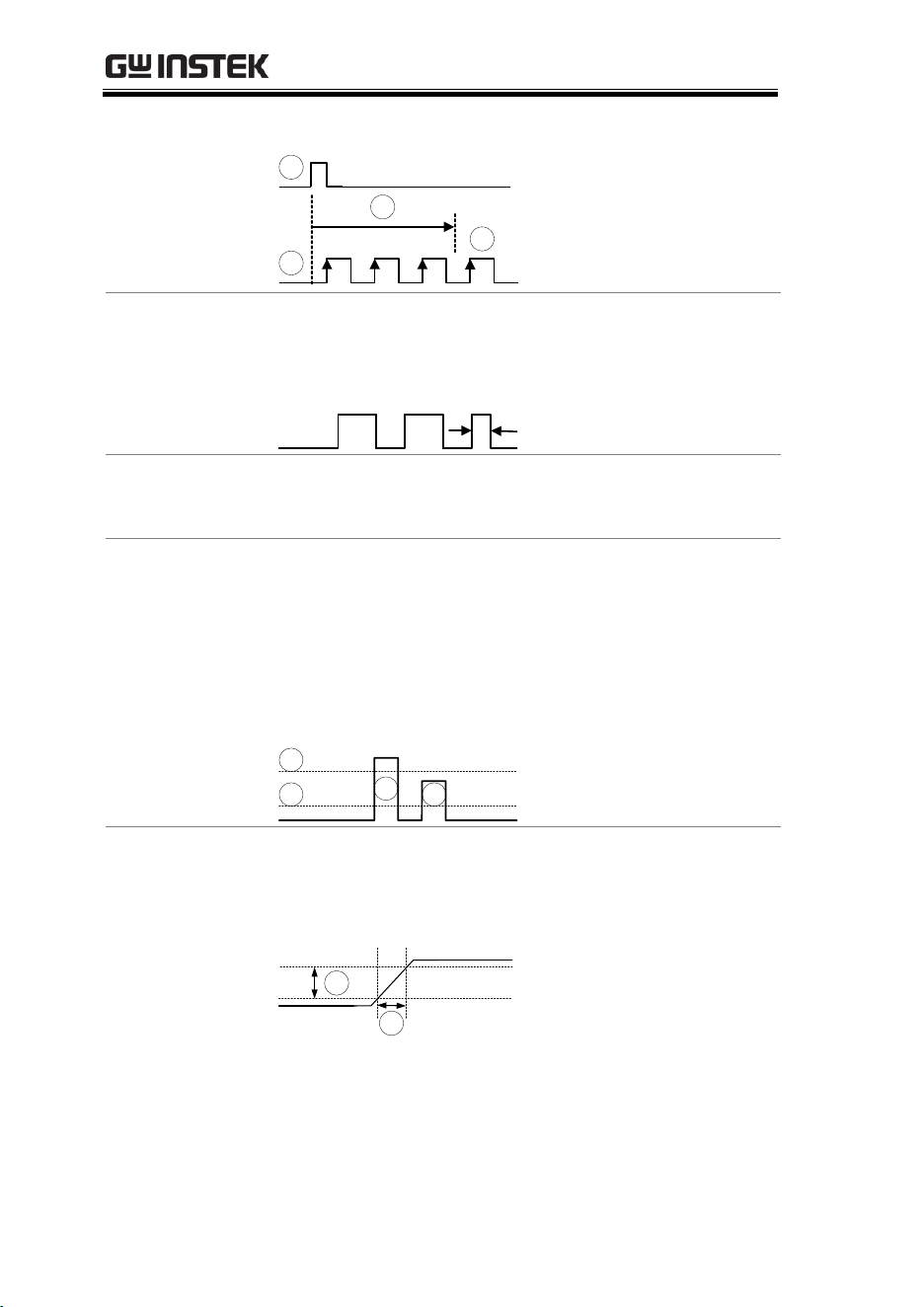
MDO-2000E series User Manual
144
Delay trigger example (by time)
A
Edge trigger
B
Delay Source
C
Delay time length
D
First triggering point
Pulse Width
Triggers when the pulse width of the signal is less
than, equal, not equal or greater than a specified
pulse width.
Pulse width
Video
Extracts a sync pulse from a video format signal,
and triggers on a specific line or field.
Pulse and Runt
Triggers on a “runt”. A runt is a pulse that passes a
specified threshold but fails to pass a second
threshold. Both positive and negative runts can be
detected.
A
Pulse
B
Runt
C
High threshold
D
Low threshold
Rise and Fall
(Slope)
Trigger on rising and or falling edges, below or
over a specified rate. The threshold can also be
specified.
A
Thresholds
B
Rate (time)
A
B
C
D
A
B
C
D
B
A
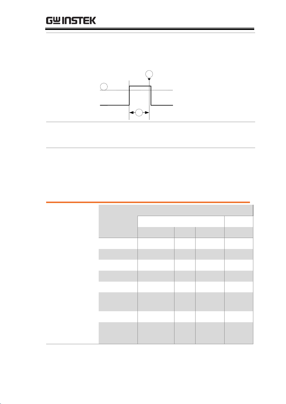
ADVANCED CONFIGURATION
145
Timeout
Triggers when the signal stays high, low or either
for a designated amount of time. The trigger level
determines when a signal is high or low.
A
B
C
A
Trigger level threshold
B
Timer
C
Triggering point
Bus
Triggers on SPI, UART, I2C, CAN or LIN bus
events.
Logic
Triggers on specified logic levels or for specified
clock edge. Logic trigger is only available for
Digital channels.
Trigger: types and sources
Sources versus
types
Trigger types
Trigger sources
Analog
Digital
CH1 ~ CH4
EXT*
AC Line
D0~D15
Edge
√
√
√
√
Delay
√
√
√
Pulse Width
√
√
√
√
Video
√
Pulse & Runt
√
Rise & Fall
(Slope)
√
Timeout
√
√
√
√
Bus
√ **
√ **
Logic
√
*Only for two channels model.
**The source analog is assigned from the Bus menu.

MDO-2000E series User Manual
146
Trigger Parameter Overview
All the following parameters are common for all
the trigger types unless stated otherwise.
Trigger Source
CH1 ~ 4
Channel 1 ~ 4 input signals
Except for: Logic
EXT *
External trigger input
signal
Except for: Video, Pulse
Runt, Rise & Fall, Bus and
Logic
*Only for 2 input models.
EXT TRIG
AC Line
AC mains signal
Except for: Video, Pulse Runt, Rise & Fall,
Bus and Logic
D0 ~ D15
Digital input channels
Except for: Video, Pulse Runt, Rise and
Fall
Alternate
Alternate between channel sources for
the trigger source.
EXT Probe
For EXT trigger source only. Set the
probe as either current or voltage.
Attenuation
For EXT trigger source only.
Attenuates the EXT trigger probe by
an adjustable value.
Range
0.001X ~ 1000X 1-2-5 steps
Source Bus
UART
UART bus
I
2
C
Inter-Integrated Circuit
SPI
Serial Peripheral Bus
Parallel
Parallel bus
CAN
Controller Area Network bus

ADVANCED CONFIGURATION
147
LIN
Local Interconnect Network
Note
The Source Bus is not configurable from the Trigger
menu. The field is automatically filled according to the
Bus menu configuration (see page 118).
Trigger Mode
Auto (un-
triggered
roll)
The MDO-2000E SERIES generates an
internal trigger if there is no trigger
event, to make sure waveforms are
constantly updated regardless of
trigger events. Select this mode
especially when viewing rolling
waveforms at slower timebases.
Normal
The MDO-2000EG/2000EX acquires a
waveform only when a trigger event
occurs.
Single
When pressing the Single
key, the MDO-2000E
SERIES acquires a
waveform only once
when a trigger event
occurs, and then stops
acquiring (the
oscilloscope falls into Stop
mode). Press the Single
key to acquire a
waveform again. Please
refer to Run/Stop mode
for more details (page 42).
Single
Coupling
(Edge, Delay,
Timeout)
DC
DC coupling.
AC
AC coupling. Blocks DC components
from the trigger circuits *.
HF reject
High frequency filter, above 70kHz*.
LF reject
Low frequency filter, below 70kHz*.
Reject noise
DC coupling with low sensitivity to
reject noise.
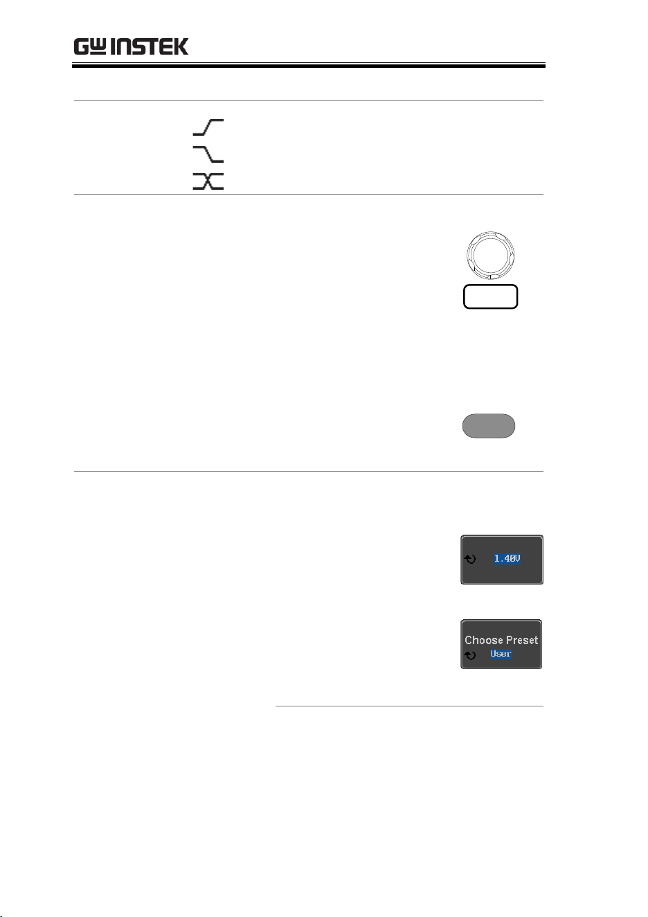
MDO-2000E series User Manual
148
*Parameter not applicable to digital channels.
Slope
(Edge, Delay, Rise
& Fall)
Trigger on a rising edge.
Trigger on a falling edge.
Either (either rising or falling edge).
Trigger Level
(Edge, Delay)
Level
Adjusts the trigger level
manually using the
Trigger LEVEL knob.
LEVEL
PUSH TO
ZERO
Set to TTL
1.4V
Sets the trigger level to 1.4V, suitable
for triggering on TTL signals.
Set to ECL -
1.3V
Sets the trigger to -1.3V. This is
suitable for ECL circuits.
Set to 50%
Sets the trigger level to
50% of the waveform
amplitude.
50 %
Level
(Edge, Delay)
Only available when the trigger source is digital.
Level
Adjusts the trigger level
when the source is digital.
Range -5V ~ +5V
Choose
Preset
Press Choose Preset to
select a pre-set logic
threshold.
Logic Type
Threshold
TTL
1.4V
5.0V CMOS
2.5V
3.3V CMOS
1.65V
2.5V CMOS
1.25V
ECL
-1.3V

ADVANCED CONFIGURATION
149
PECL
3.7V
0V
0V
Note
Setting the trigger levels for the digital sources
will also change the threshold levels set in the
Logic Analyzer menu (page 207).
Holdoff
Holdoff
Sets the holdoff time.
Set to
Minimum
Set the holdoff time to the minimum.
Delay
(Delay)
Time
Sets the delay time (4ns ~ 10s)
between the trigger event and the real
trigger timing.
Event
Sets the number of events (1 ~ 65535)
passed after the trigger event, until the
real trigger timing.
Set to
Minimum
Sets the source trigger to the
minimum time.
When
(Pulse Width)
Sets the pulse width (4ns ~ 10s) and the triggering
condition.
>
Longer than
=
Equal to
<
Shorter than
≠
Not equal to
Threshold
(Pulse Width)
Sets the amplitude threshold level for the pulse
widths.
Threshold
–XXV ~ +XXV, user-set level
Set to TTL
1.4V
Set to ECL
-1.3V
Set to 50%
Sets the threshold to 50%
(Only when the trigger source is digital):
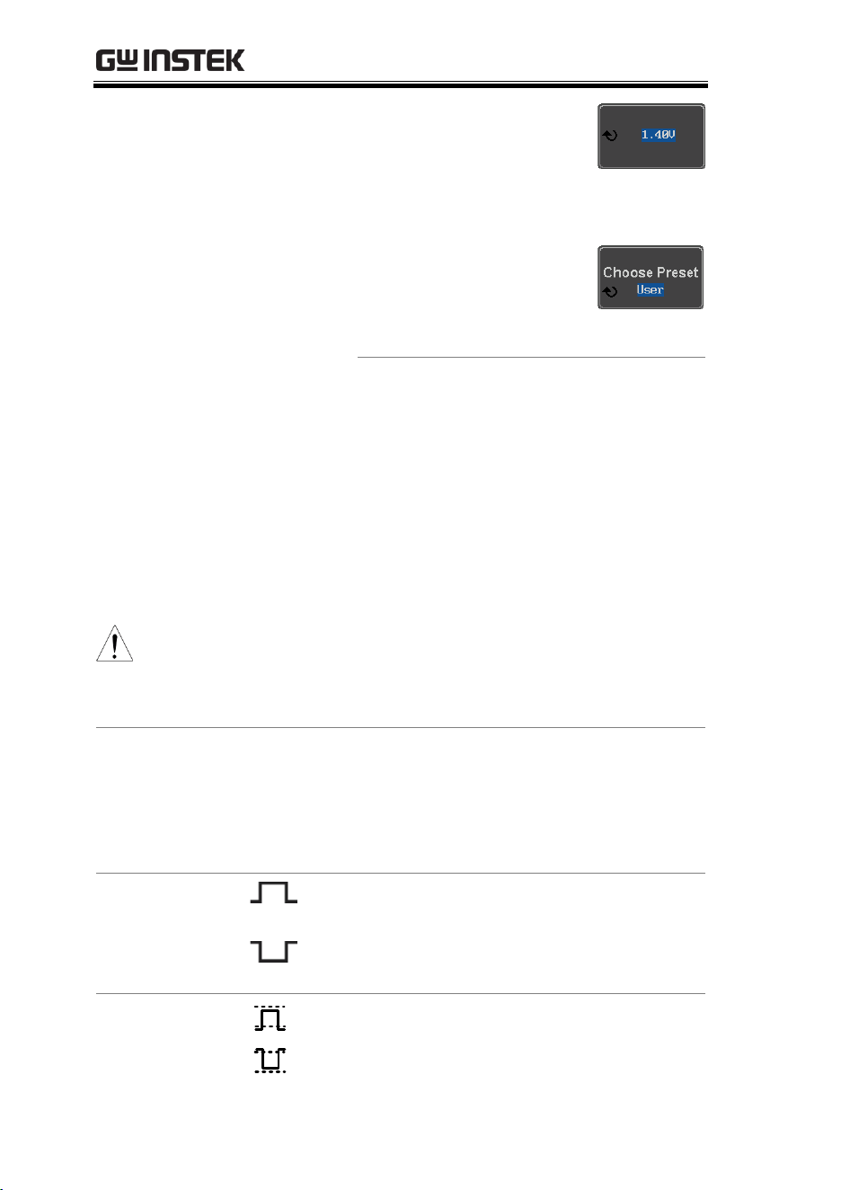
MDO-2000E series User Manual
150
Threshold
Adjusts the amplitude
threshold for the pulse
width trigger when the
source is digital.
Range -5V ~ +5V
Choose
Preset
Press Choose Preset to
select a pre-set logic
threshold.
Logic Type
Threshold
TTL
1.4V
5.0V CMOS
2.5V
3.3V CMOS
1.65V
2.5V CMOS
1.25V
ECL
-1.3V
PECL
3.7V
0V
0V
Note
Setting the threshold levels for the digital sources
from the Trigger menu will also change the
threshold levels set in the Logic Analyzer menu
(page 207).
Standard
(Video)
NTSC
National Television System
Committee
PAL
Phase Alternate by Line
SECAM
SEquential Couleur A Memoire
Polarity
(Pulse Width,
Video)
Positive polarity (triggered on the
high to low transition)
Negative polarity (triggered on the
low to high transition)
Polarity
(Pulse Runt)
Positive polarity (positive runt)
Negative polarity (negative runt)

ADVANCED CONFIGURATION
151
Either (either negative or positive
runt)
Trigger On
(Video)
Selects the trigger point in the video signal.
Odd Field
NTSC: 1 ~ 263
PAL/SECAM: 1 ~ 313
EDTV: 1~525(480P), 1~625(576P)
HDTV: 1~750(720P), 1~563(1080i),
1~1125(1080P)
Even Field
NTSC: 1 ~ 262, PAL/SECAM: 1 ~ 312
HDTV: 1~562(1080i)
All Fields
Triggers on all fields.
All Lines
Triggers on all lines.
Trigger On
(Bus)
Selects the conditions for the serial bus triggers.
UART Bus
Tx Start Bit, Rx Start Bit, Tx End of
Packet, Rx End of Packet, Tx Data, Rx
Data, Tx Parity Error, Rx Parity Error
I
2
C
Start, Repeat Start, Stop, Missing Ack,
Address, Data, Address/Data
SPI
SS Active, MOSI, MISO, MOSI&MISO
CAN
Start of Frame, Type of Frame,
Identifier, Data, Id & Data, End of
Frame, Missing Ack, Bit Stuffing Err
LIN
Sync, Identifier, Data, Id & Data,
Wakeup Frame, Sleep Frame, Error
Data
(Bus)
Selects the conditions for the parallel bus trigger.
Parallel
A Binary or Hexadecimal word.
Threshold
(Pulse Runt)
Sets the upper threshold limit.
Sets the lower threshold limit.
Threshold
Sets the High threshold.

MDO-2000E series User Manual
152
(Rise & Fall)
Sets the Low threshold.
Trigger When
(Timeout)
Stays High
Triggers when the input signal stays
high for a designated amount of time.
Stays Low
Triggers when the input signal stays
low for a designated amount of time.
Either
Triggers when the input signal stays
high or low for a designated amount
of time.
Timer
(Timeout)
4nS~10.0S
Sets the amount of time that a signal
must stay high or low for the timeout
trigger.
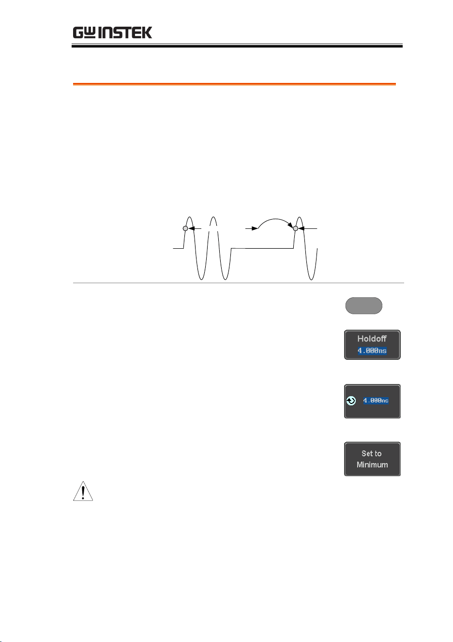
ADVANCED CONFIGURATION
153
Setup Holdoff Level
Background
The holdoff function defines the waiting period
before the MDO-2000E starts triggering again after
a trigger point. The holdoff function ensures a
stable display if there are a number of points in a
periodic waveform that can be triggered. Holdoff
applies to all the triggering types except the trigger
by bus.
Wait for
trigger
Holdoff time
Trigger point
Next trigger point
Panel Operation
1. Press the trigger Menu key.
Menu
2. To set the Holdoff time, press the
Holdoff (or Mode/Holdoff) menu
button on the bottom bezel.
3. Use the side menu to set the
Holdoff time.
Range
4ns~10s
Pressing Set to Minimum sets the
Holdoff time to the minimum, 4ns.
Note
Note: The holdoff function is automatically
disabled when the waveform update mode is in roll
mode (page 104).
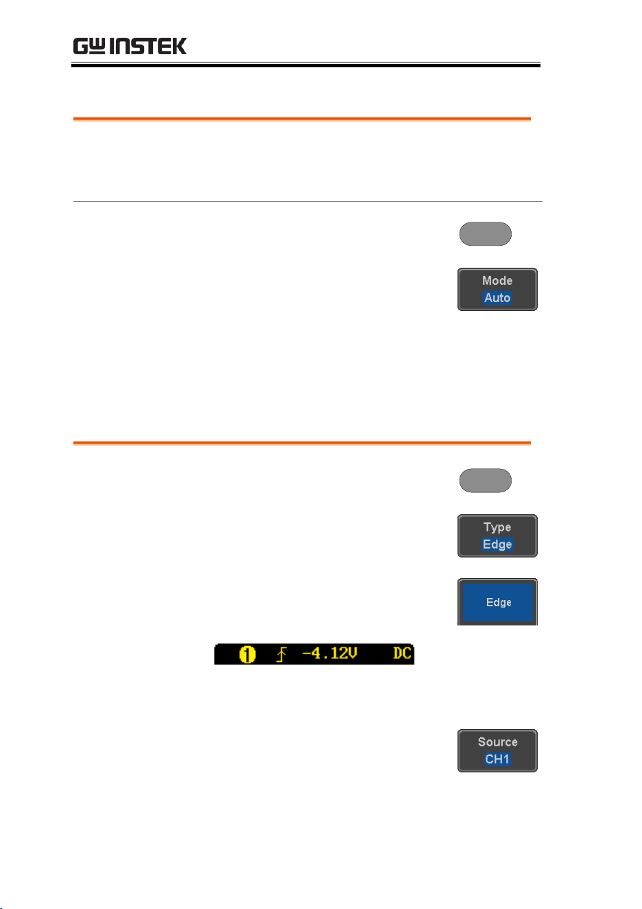
MDO-2000E series User Manual
154
Setup Trigger Mode
Background
The trigger mode can be set to Normal or Auto
(untriggered roll). The triggering mode applies to
all the trigger types.
Panel Operation
1. Press the Trigger menu key.
Menu
2. Press Mode from the bottom menu
to change the triggering mode.
3. Use the side panel to select Auto or
Normal triggering modes.
Range
Auto, Normal
Using the Edge Trigger
Panel Operation
1. Press the trigger Menu key.
Menu
2. Press Type from the lower bezel
menu.
3. Select Edge from the side menu.
The edge trigger indicator appears
at the bottom of the display.
From left: trigger source, slope, trigger level,
coupling
4. Press Source to change the trigger
source.
5. Use the side menu to select the trigger source
type.
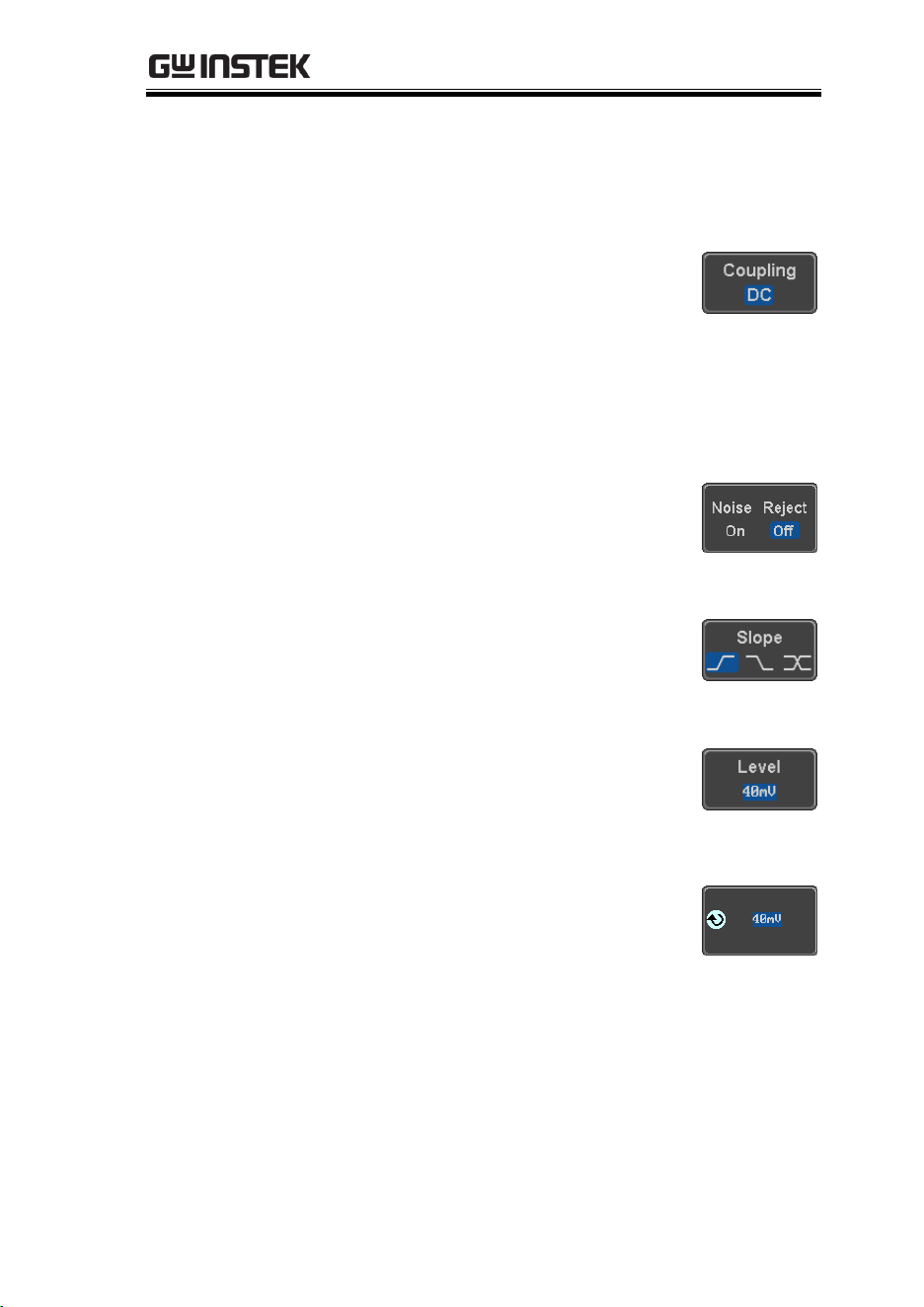
ADVANCED CONFIGURATION
155
Range
Channel 1 ~ 4 (Alternate On/Off),
EXT (Ext Probe: Volt/Current,
Attenuation: 1mX~1kX, CH2
models only), AC Line and D0~D15.
6. Press Coupling from the bottom
bezel menu to select the trigger
coupling or frequency filter
settings.
Choose the coupling from the side menu.
Range
DC, AC, HF Reject, LF Reject
7. Toggle Noise Rejection On or Off
from the side menu.
Range
On, Off
8. From the bottom menu press Slope
to toggle the slope type.
Range
Rising edge, falling edge, either
9. To set the external trigger level,
select Level from the bottom bezel
menu (Not applicable for AC line
source).
10. Set the external trigger level using
the side menu.
Analog
channel
Range
00.0V~ 5 screen divisions
Set to TTL 1.4V
Set to ECL -1.3V
Set to 50%
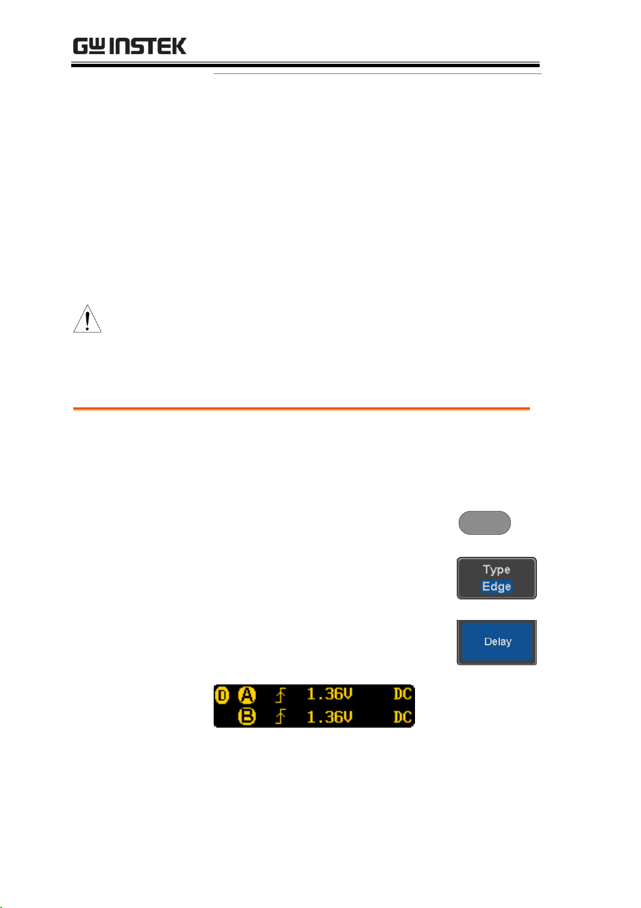
MDO-2000E series User Manual
156
Digital
channel
Range
-5.00V~ +5.00V
TTL 1.4V
5.0V CMOS 2.5V
3.3V CMOS 1.65V
2.5V CMOS 1.25V
ECL -1.3V
PECL 3.7V
0V 0V
Note
Setting the trigger level for a digital source will
also change the threshold levels set in the Logic
Analyzer menu (page 207).
Using Advanced Delay Trigger
Panel Operation
1. Set the edge trigger source. This
will set the initializing trigger for
the delay source.
Page 154
2. Press the trigger Menu key.
Menu
3. Press Type from the lower bezel
menu.
4. Select Delay from the side menu.
The delay trigger indicator appears
at the bottom of the display.
From left: Delay trigger indicator (D),
edge trigger (A), edge slope, edge level, edge
coupling, delay trigger (B), delay slope, delay
trigger level, delay coupling.
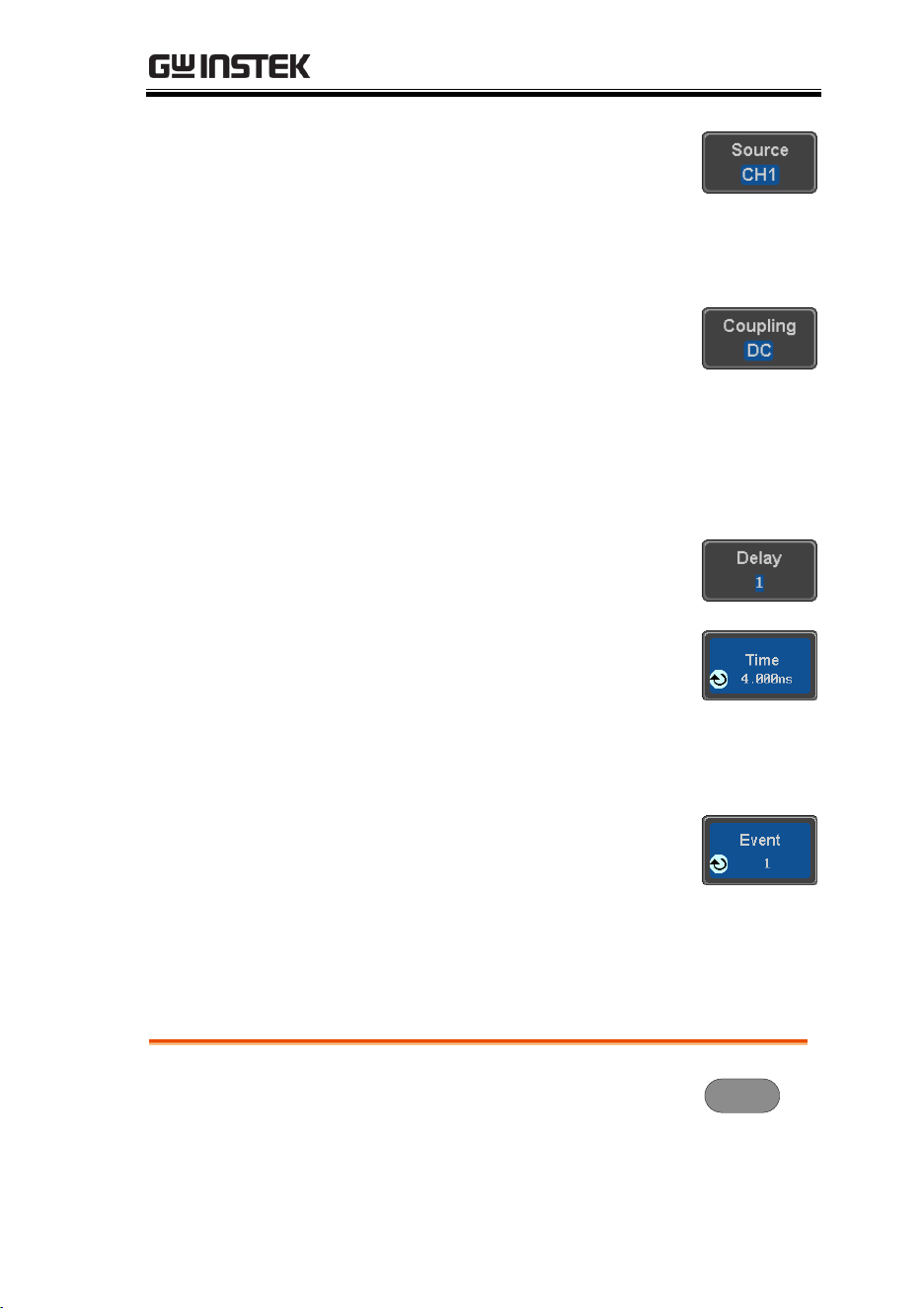
ADVANCED CONFIGURATION
157
5. To set the delay source, press
Source and select a source from the
side menu.
Source
CH1 ~ CH4, AC Line, EXT*
*2 channel models only.
6. Press Coupling from the bottom
bezel menu to select the trigger
coupling or frequency filter
settings.
Choose the coupling from the side menu.
Range
DC, AC, HF Reject, LF Reject
7. To set the delay press Delay from
the bottom bezel.
8. To Delay by Time (Duration), press
Time from the side menu and set
the delay time.
Range
4ns ~ 10s (by time)
Set to minimum
9. To Delay by Event, press Event
from the side menu and set the
number of events.
Range
1 ~ 65535 events
Set to Minimum
Using Pulse Width Trigger
Panel Operation
1. Press the trigger Menu key.
Menu
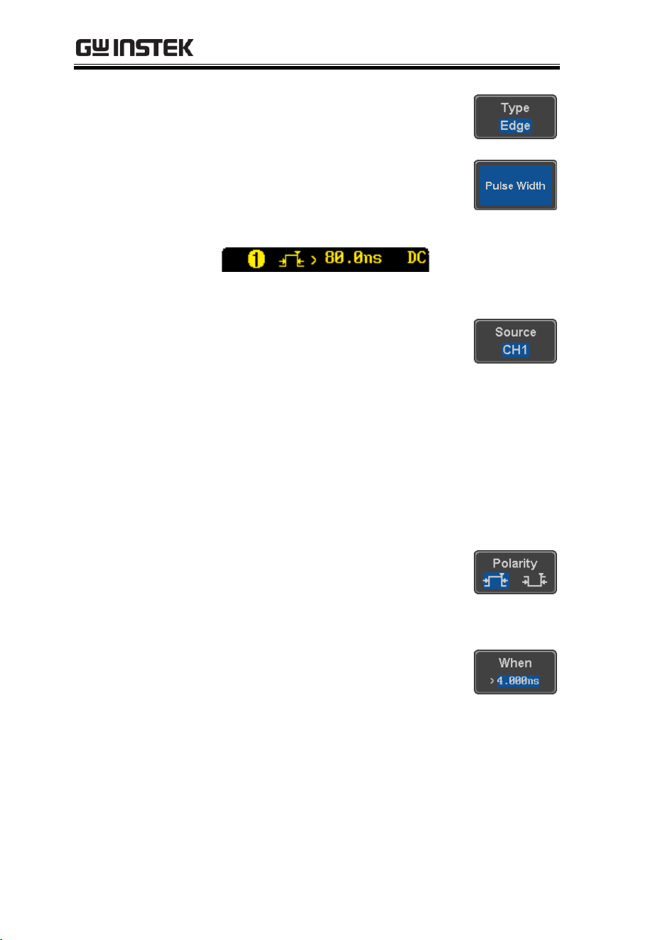
MDO-2000E series User Manual
158
2. Press the Type key from the lower
bezel menu.
3. Select Pulse Width from the side
menu. The pulse width trigger
indicator appears at the bottom of
the display.
From left: source, polarity, when, coupling
4. Press Source from the lower bezel.
5. Use the side menu to select the pulse width
trigger source.
Range
Channel 1 ~ 4 (Alternate On/Off),
EXT (Ext Probe: Volt/Current,
Attenuation: 1mX~1kX, CH2
models only), AC Line and D0 ~
D15.
6. Press Polarity to toggle the polarity
type.
Range
Positive (high to low transition)
Negative (low to high transition)
7. Press When from the lower bezel.
Then use the side menu to select the pulse
width condition and width.
Condition
> , < , = , ≠
Width
4ns ~ 10s
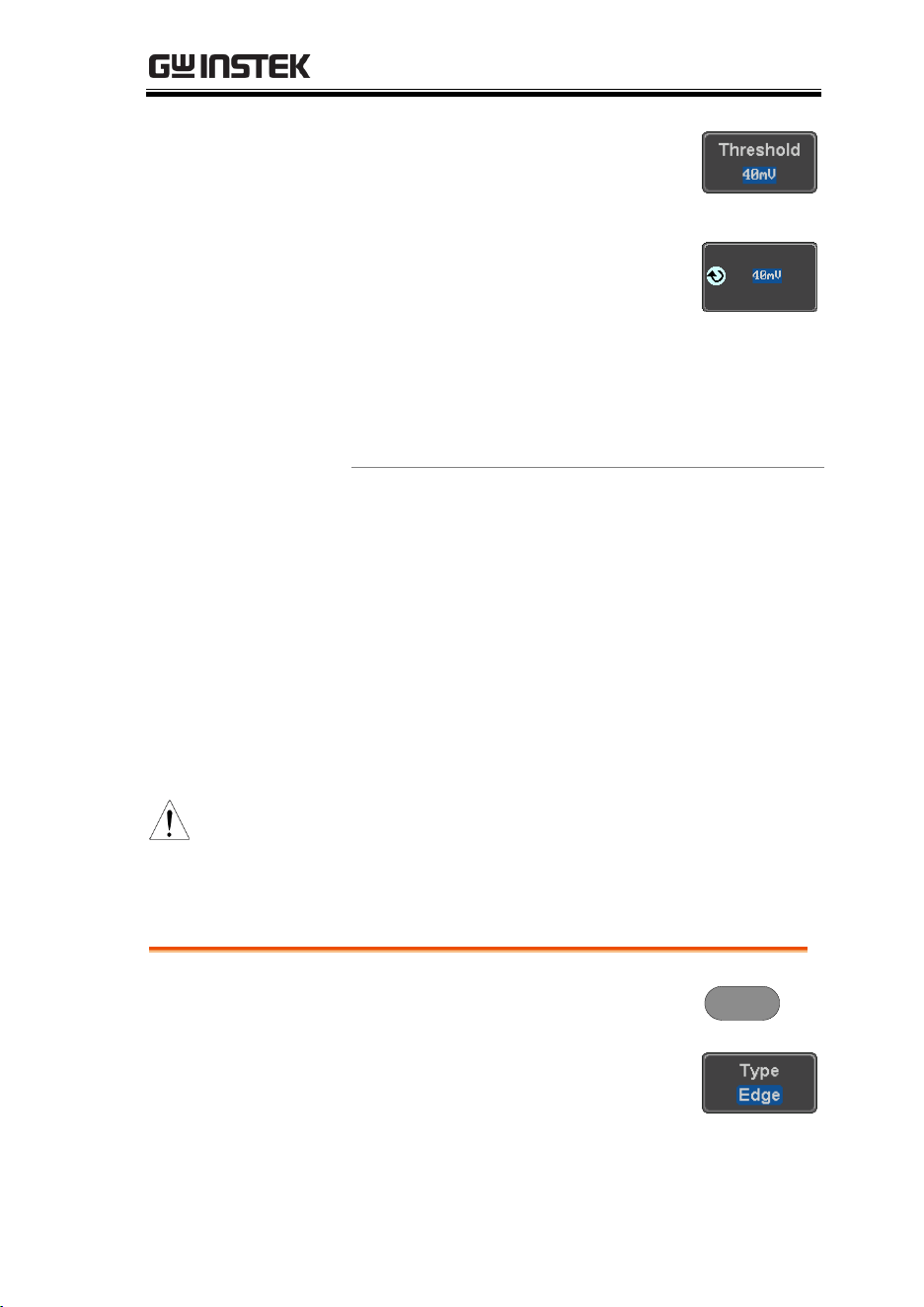
ADVANCED CONFIGURATION
159
8. Press Threshold from the lower
bezel to edit the pulse width
threshold.
9. Set the threshold level using the
side menu.
Analog
channel
Range
00.0V~ 5 screen divisions
Set to TTL 1.4V
Set to ECL -1.3V
Set to 50%
Digital
channel
Range
-5.00V~ +5.00V
TTL 1.4V
5.0V CMOS 2.5V
3.3V CMOS 1.65V
2.5V CMOS 1.25V
ECL -1.3V
PECL 3.7V
0V 0V
Note
Setting the trigger threshold for a digital source
will also change the threshold levels set in the
Logic Analyzer menu (page 207).
Using Video Trigger
Panel Operation
1. Press the trigger Menu key.
Menu
2. Press the Type key from the lower
bezel menu.
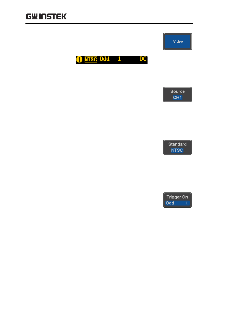
MDO-2000E series User Manual
160
3. Select Video from the side menu.
The video trigger indicator appears
at the bottom of the display.
From left: source, video standard, field, line,
coupling
4. Press Source from the lower bezel.
5. Use the side menu to select the
video trigger source.
Range
Channel 1 ~ 4
6. Press Standard on the bottom bezel.
Use the side menu to select the video standard.
Range
NTSC, PAL, SECAM, EDTV(480P,
576P), HDTV(720P, 1080i, 1080P)
7. Press Trigger On to edit the video
field and line.
Use the side menu to select the field and line.
Odd Field
NTSC: 1 ~ 263
PAL/SECAM: 1 ~ 313
EDTV: 1~525(480P), 1~625(576P)
HDTV: 1~750(720P), 1~562(1080i),
1~1125(1080P)
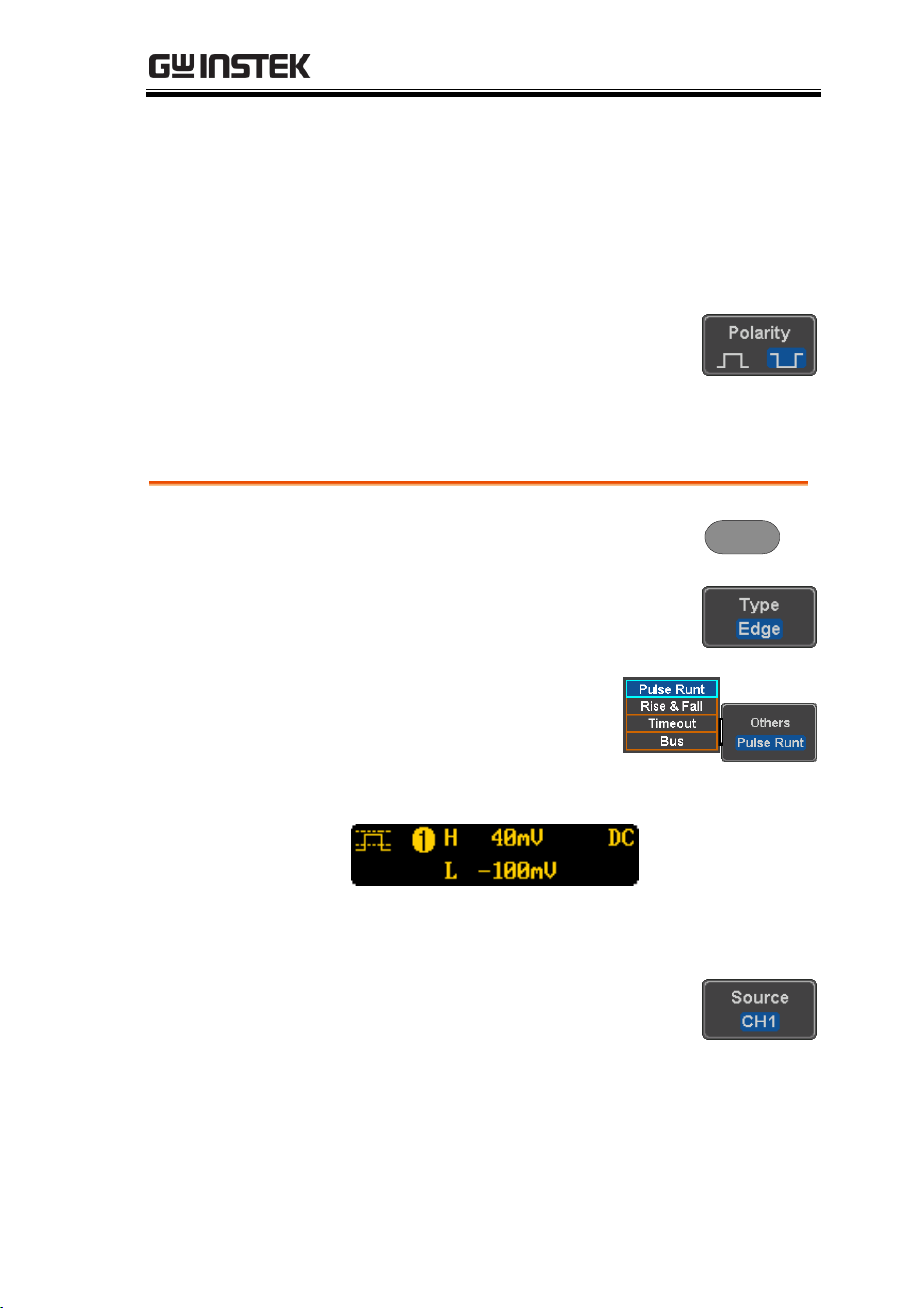
ADVANCED CONFIGURATION
161
Even Field
NTSC: 1 ~ 262
PAL/SECAM: 1 ~ 312
HDTV: 1~563(1080i)
All Fields
Triggers on all fields.
All Lines
Triggers on all lines.
8. Press Polarity to toggle the polarity
type.
Range
positive, negative
Pulse Runt trigger
Panel Operation
1. Press the trigger Menu key.
Menu
2. Press the Type key from the lower
bezel menu.
3. Select Others → Pulse Runt
from the side menu. The
Pulse and Runt indicator
appears at the bottom of
the display.
From left: polarity, source, high/low threshold,
threshold level, coupling
4. Press Source from the lower menu.
Use the side menu to select a source.
Range
Channel 1 ~ 4(Alternate On/Off)
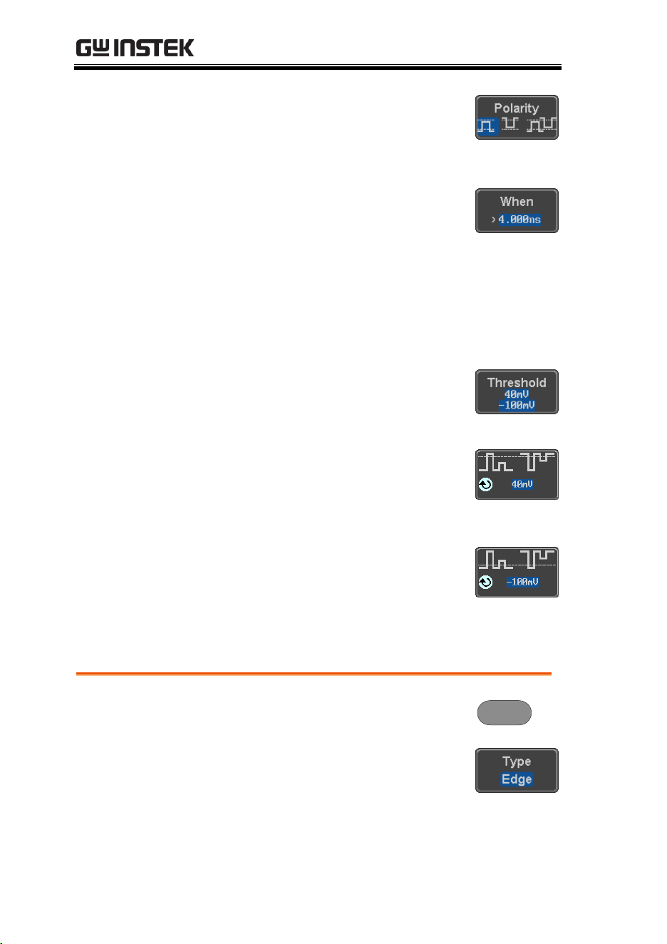
MDO-2000E series User Manual
162
5. Press Polarity to toggle the polarity.
Range
Rising edge, falling edge, either.
6. Press When from the lower menu.
Then use the side menu to select the condition
and width.
Condition
> , < , = , ≠
Width
4ns ~ 10s
7. Press Threshold from the lower
bezel to edit the threshold for the
upper and lower threshold.
8. Use the side menu to set the upper
threshold.
Range
-XXV~XXV
9. Use the side menu to set the lower
threshold.
Range
-XXV~XXV
Using Rise and Fall Trigger
Panel Operation
1. Press the trigger Menu key.
Menu
2. Press the Type key from the lower
bezel menu.
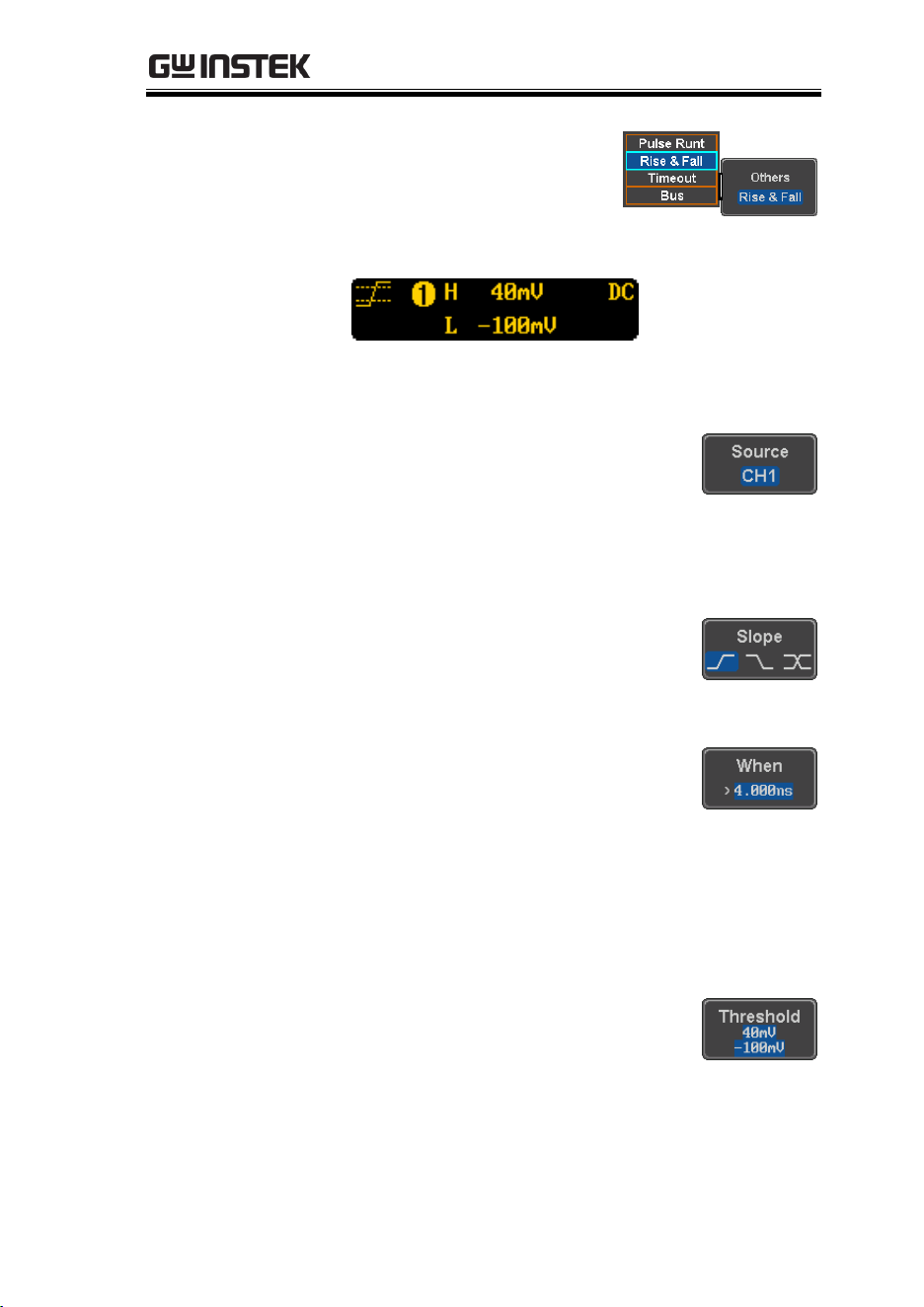
ADVANCED CONFIGURATION
163
3. Select Others
Rise and
Fall from the side menu.
The Rise and Fall indicator
appears at the bottom of
the display.
From left: slope, source, high/low threshold,
threshold level, coupling
4. Press Source from the lower menu.
Use the side menu to select a source.
Range
Channel 1 ~ 4(Alternate On/Off)
5. Press Slope from the bottom menu
to toggle the slope.
Range
Rising edge, falling edge, either
6. Press When from the lower menu.
Then use the side menu to select the logic
conditions and true or false status.
Condition
> , < , = , ≠
Width
4ns ~ 10s
7. Press Threshold from the lower
bezel to edit the High and Low
threshold.
Range
High: -XXV~XXV
Low: -XXV~XXV
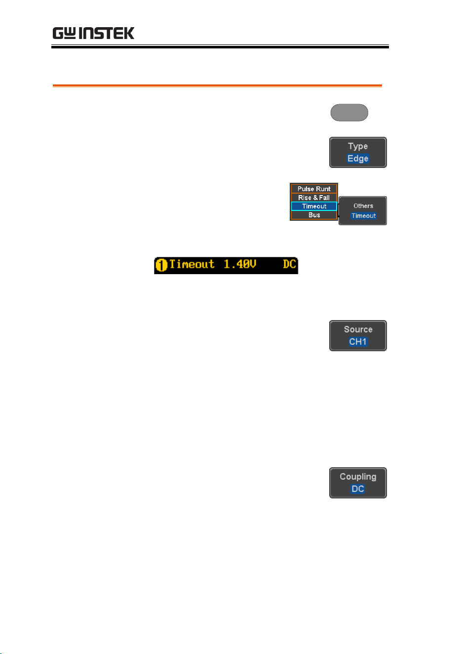
MDO-2000E series User Manual
164
Using the Timeout Trigger
Panel Operation
1. Press the trigger Menu key.
Menu
2. Press the Type key from the lower
bezel menu.
3. Select Others
Timeout
from the side menu. The
Timeout indicator appears
at the bottom of the
display.
From left: Source, Trigger type, threshold level,
coupling
4. Press Source from the lower menu.
Use the side menu to select a source.
Range
Channel 1 ~ 4 (Alternate On/Off),
EXT (Ext Probe: Volt/Current,
Attenuation: 1mX~1kX, CH2
models only), AC Line and D0 ~
D15.
5. Press Coupling from the bottom
bezel menu to select the trigger
coupling or frequency filter
settings.
Choose the coupling from the side menu.
Range
DC, AC, HF Reject, LF Reject
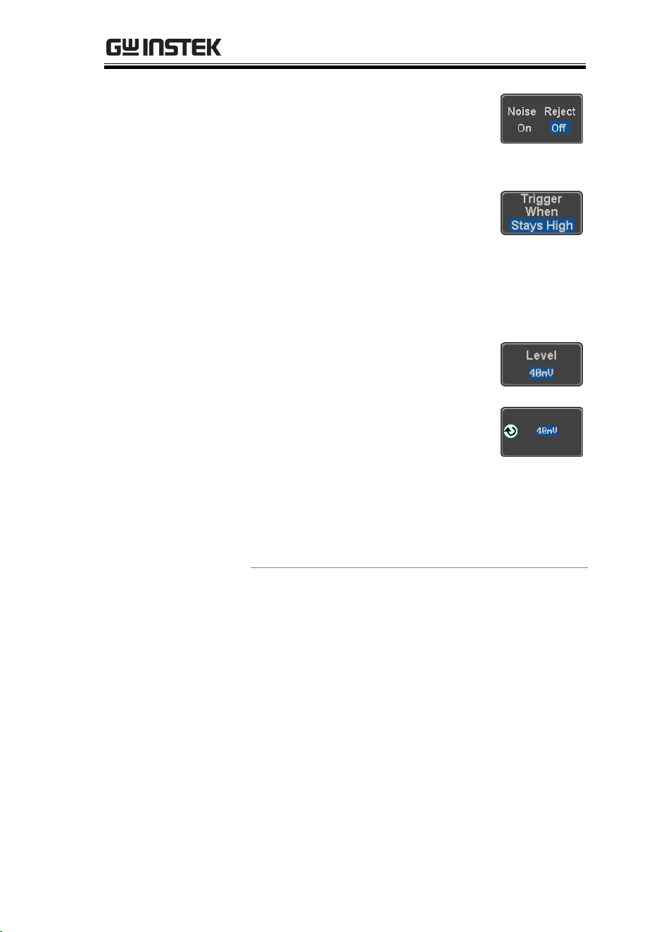
ADVANCED CONFIGURATION
165
6. Toggle Noise Rejection On or Off
from the Coupling side menu.
Range
On, Off
7. Press Trigger When from the lower
menu.
Then use the side menu to select trigger
conditions.
Condition
Stays High, Stays Low, Either
8. Press Level from the lower bezel to
set the trigger level.
9. Set the level using the side menu.
Analog
channel
Range
00.0V~ 5 screen divisions
Set to TTL 1.4V
Set to ECL -1.3V
Set to 50%
Digital
channel
Range
-5.00V~ +5.00V
TTL 1.4V
5.0V CMOS 2.5V
3.3V CMOS 1.65V
2.5V CMOS 1.25V
ECL -1.3V
PECL 3.7V
0V 0V
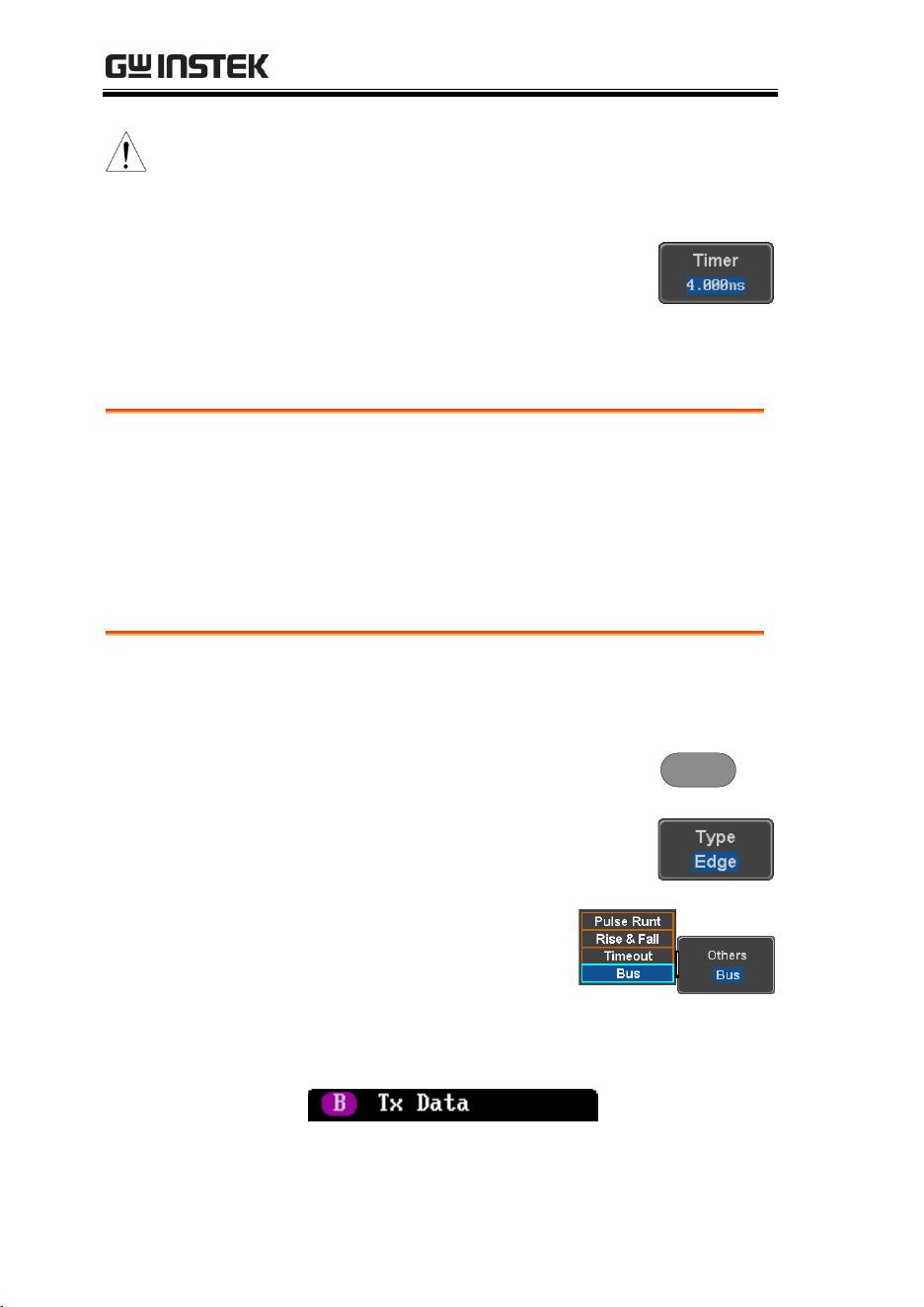
MDO-2000E series User Manual
166
Note
Setting the trigger threshold for a digital source
will also change the threshold levels set in the
Logic Analyzer menu (page 207).
10. Press Timer from the lower bezel to
set the timer time.
Range
4ns~10.0S
Using the Bus Trigger
The Bus trigger is used to trigger the oscilloscope on UART, I2C, SPI,
CAN or LIN serial bus signals or on bus data.
UART BUS Trigger Settings
The UART bus trigger conditions can be set at any time after the
bus settings have been set to UART.
Panel Operation
1. Set the Bus to UART in the bus
menu.
Page 122
2. Press the Trigger Menu key.
Menu
3. Press Type from the bottom menu.
4. Press Others from the side
menu and select Bus.
The Trigger on settings will be reflected on the
Trigger Configuration icon.
From left: Bus trigger, Trigger source
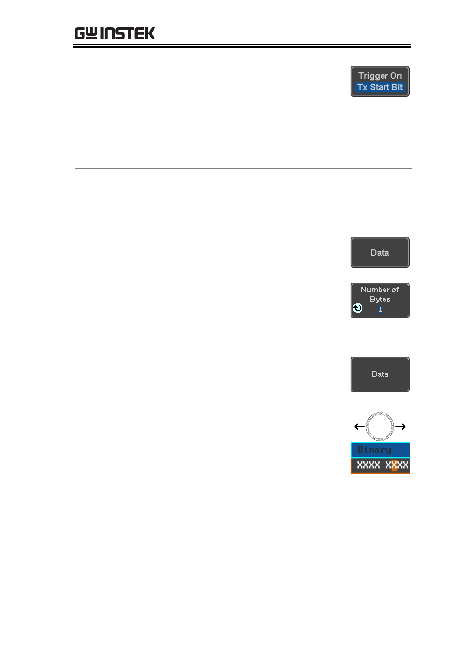
ADVANCED CONFIGURATION
167
5. Press Trigger On and select the
triggering condition for the UART
bus.
Trigger On
Tx Start Bit, Rx Start Bit, Tx End of
Packet, Rx End of Packet, Tx Data,
Rx Data, Tx Parity Error, Rx Parity
Error
Trigger On – Tx
Data, Rx Data
If Tx Data or Rx Data was configured for the
Trigger On setting, then the number of bytes and
data can also be configured.
6. Press Data from the bottom menu.
7. Press Number of Bytes from the side
menu and choose the number of
bytes for the data.
UART
1~10 Bytes
8. Press Data from the side menu to
edit the triggering data.
To edit the data, use the Variable
knob to highlight a binary or hex
digit and press Select. Use the
Variable knob to choose a value for
the digit and press Select to
confirm.
VARIABLE
Binary
0,1,X (don’t care)
Hex
0~F, X (don’t care)
ASCII
ASCII characters for the equivalent
Hex characters 00 to FF
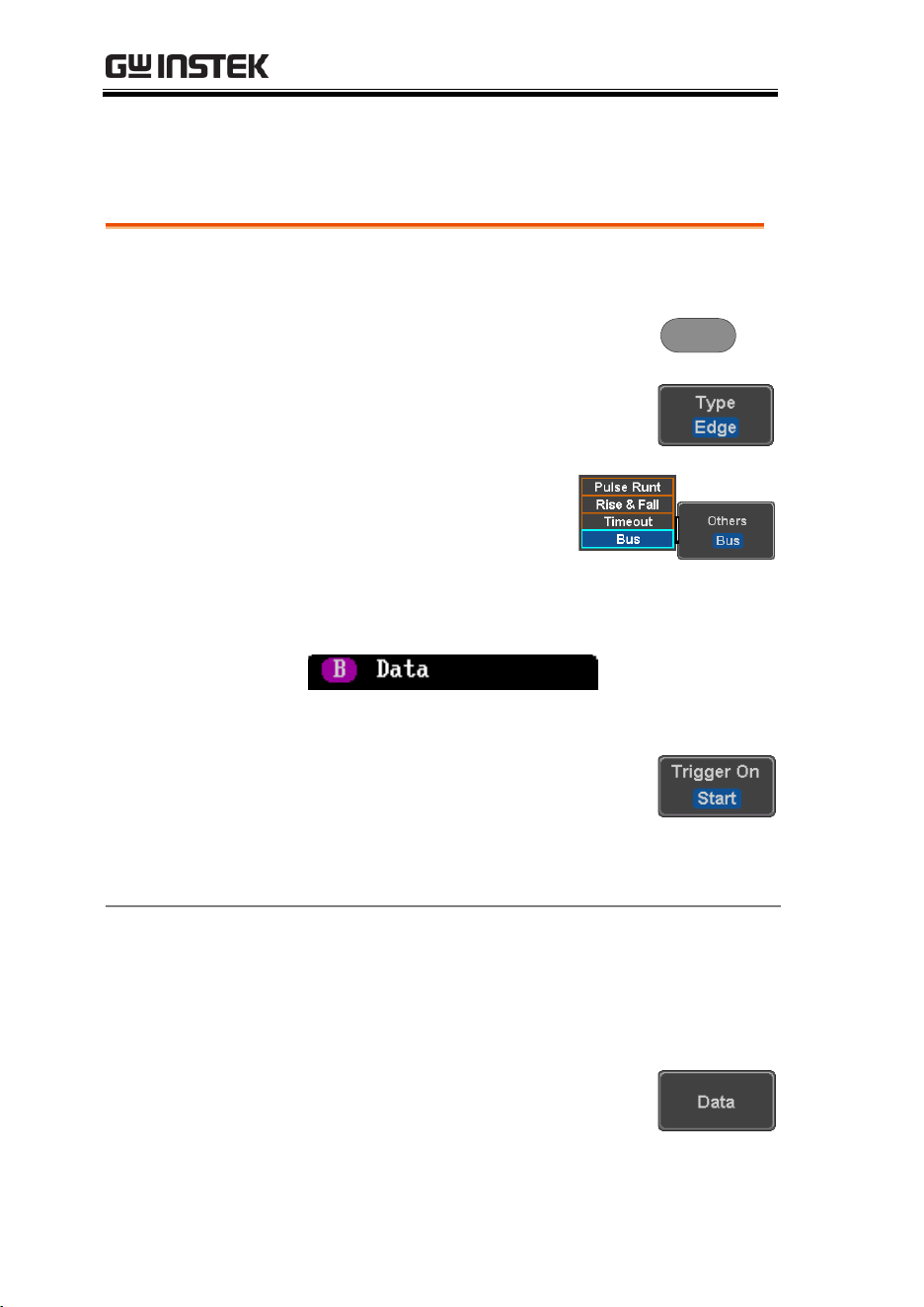
MDO-2000E series User Manual
168
I
2
C Bus Trigger Settings
The I
2
C bus trigger conditions can be set at any time after the bus
settings has been set to I
2
C.
Panel Operation
1. Set the Bus to I
2
C in the bus menu.
Page 124
2. Press the Trigger Menu key.
Menu
3. Press Type from the bottom menu.
4. Press Others from the side
menu and select Bus.
The Trigger on settings will be reflected on the
Trigger Configuration icon.
From left: Bus trigger, Trigger source
5. Press Trigger On and select the
triggering condition for the
selected bus.
Trigger On
Start, Repeat Start, Stop, Missing
Ack, Address, Data, Address/Data
Trigger On – Data
If Data or Address/Data was configured for the
Trigger On setting, then the number of bytes,
data and addressing mode (I
2
C) can be
configured.
6. Press Data from the bottom menu.
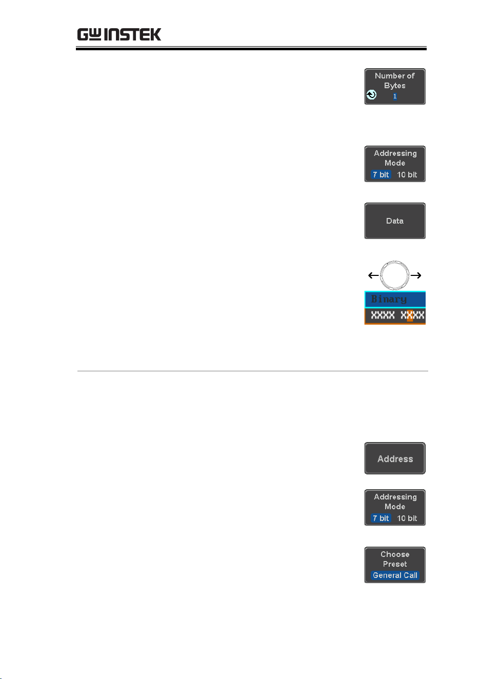
ADVANCED CONFIGURATION
169
7. Press Number of Bytes from the side
menu and choose the number of
bytes for the data.
I
2
C
1~5 Bytes
8. Press Addressing Mode to toggle
between 7 and 10 bit addressing
modes.
9. Press Data from the side menu to
edit the triggering data.
To edit the data, use the Variable
knob to highlight a binary or hex
digit and press Select. Use the
Variable knob to choose a value for
the digit and press Select to
confirm.
VARIABLE
Binary
0,1,X (don’t care)
Hex
0~F, X (don’t care)
Trigger On -
Address
If Address or Address/Data was configured for
the Trigger On setting, then the triggering
address must be configured.
10. Press Address on the bottom menu.
11. Press Addressing Mode to toggle
between 7 and 10 bit addressing
modes.
12. To choose a preset address as the
default address, press Choose Preset
and select a preset address.
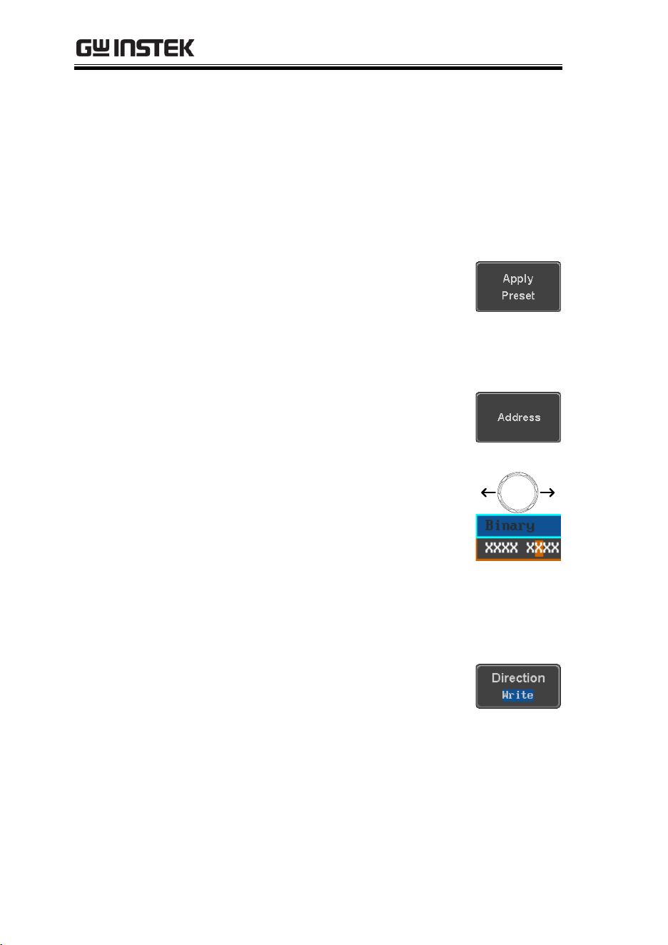
MDO-2000E series User Manual
170
Address
Description
0000 000 0
General Call
0000 000 1
START Byte
0000 1XX X
Hs-mode
1010 XXX X
EEPROM
0000 001 X
CBUS
Press Apply Preset to set the default
address to the preset.
Note
Presets are not available for Trigger On
Address/Data.
13. Press Address from the side menu
to manually edit the triggering
address.
To edit the address, use the
Variable knob to highlight a binary
or hex digit and press Select. Use
the Variable knob to choose a value
for the digit and press Select to
confirm.
VARIABLE
Binary
0,1, X (don’t care)
Hex
0~F, X (don’t care)
Direction
14. Press Direction on the bottom menu
and choose the direction from the
side menu.
Direction
Write, Read, Read or Write
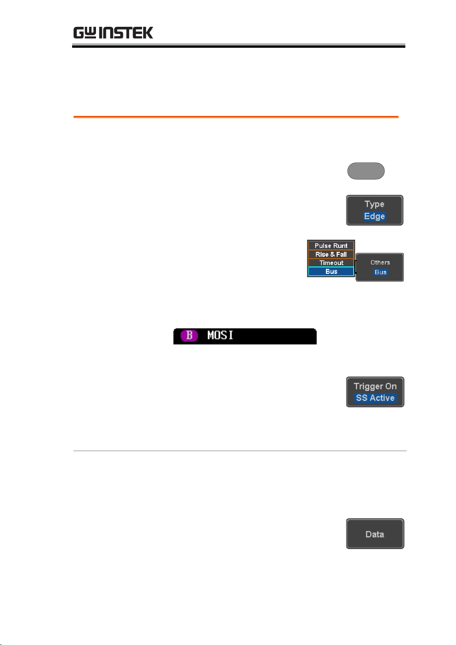
ADVANCED CONFIGURATION
171
SPI Bus Trigger Settings
The SPI bus trigger conditions can be set at any time after the bus
setting has been set to SPI.
Panel Operation
1. Set the Bus to SPI in the bus menu.
Page 126
2. Press the Trigger Menu key.
Menu
3. Press Type from the bottom menu.
4. Press Others from the side
menu and select Bus.
The Trigger on settings will be reflected on the
Trigger Configuration icon.
From left: Bus trigger, Trigger source
5. Press Trigger On and select the
triggering condition for the SPI
bus.
SPI
SS Active, MOSI, MISO,
MOSI&MISO
Trigger On – Data
If MOSI, MISO or MISO/MOSI was configured
for the Trigger On setting, then the number of
words and the data can be configured.
6. Press Data from the bottom menu.
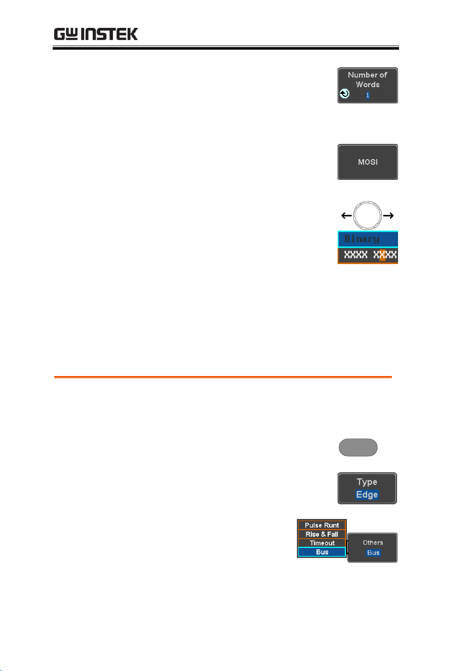
MDO-2000E series User Manual
172
7. Press Number of Words from the
side menu and choose the number
of words for the data.
SPI
1~32 Words
8. Press MOSI or MISO from the side
menu to edit the triggering data.
To edit the data, use the Variable
knob to highlight a binary or hex
digit and press Select. Use the
Variable knob to choose a value for
the digit and press Select to
confirm.
VARIABLE
Binary
0,1,X (don’t care)
Hex
0~F, X (don’t care)
CAN Bus Trigger
The CAN bus trigger conditions can be set at any time after the bus
setting has been set to CAN.
Panel Operation
1. Set the Bus to CAN in the bus
menu.
Page 128
2. Press the Trigger Menu key.
Menu
3. Press Type from the bottom menu.
4. Select Others → Bus from
the side menu. The Bus
indicator appears at the
bottom of the display.
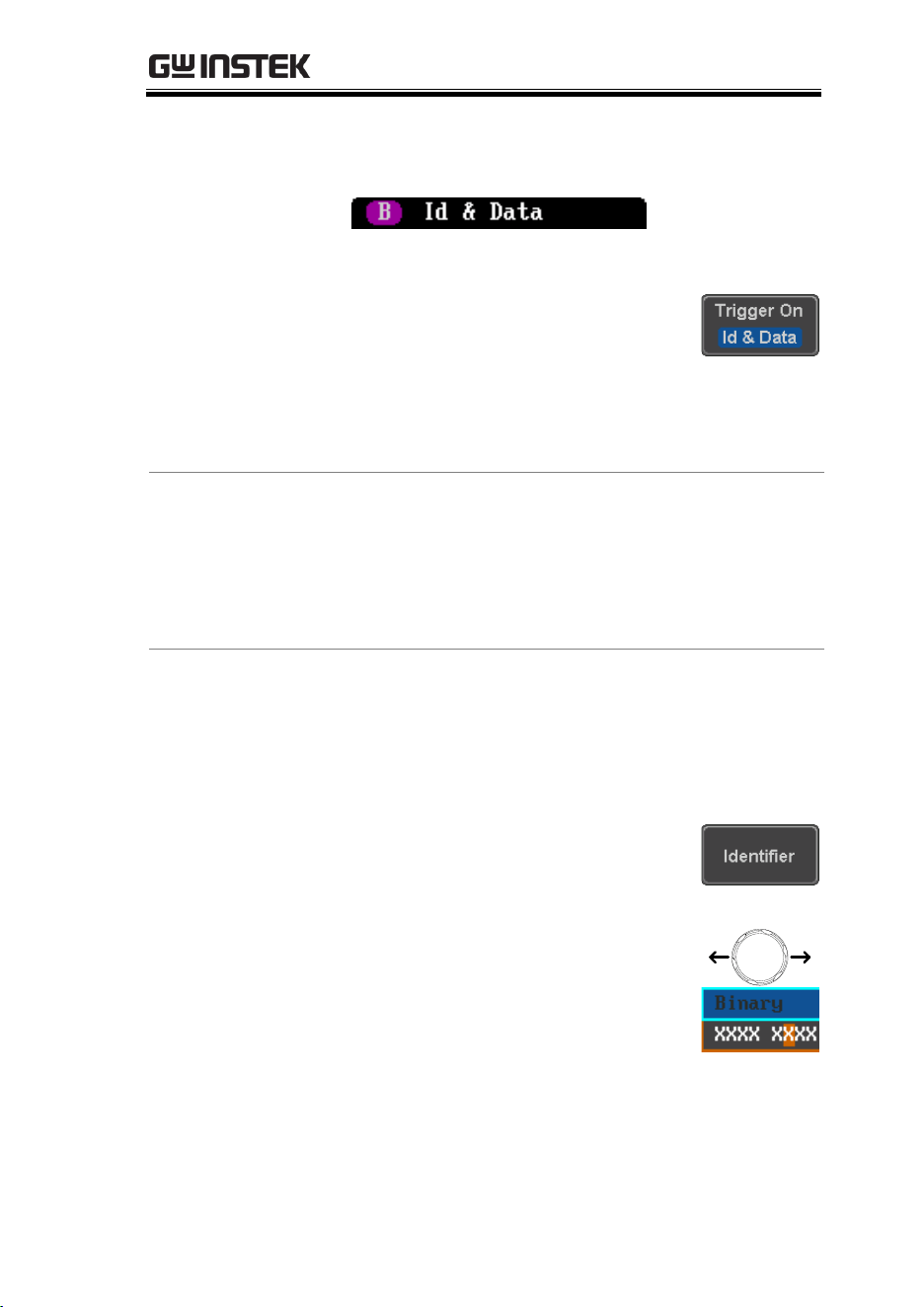
ADVANCED CONFIGURATION
173
The Trigger on settings will be reflected on the
Trigger Configuration icon.
From left: Bus trigger, Trigger source
5. Press Trigger On and select the
triggering condition for the
selected bus.
Trigger On
Start of Frame, Type of Frame,
Identifier, Data, Id & Data, End of
Frame, Missing Ack, Bit Stuffing Err
Trigger On –Type
of Frame
6. If Type of Frame was configured for the Trigger
On setting, then the type of frame can be
configured from the side menu.
Type
Data Frame, Remote Frame, Error
Frame, Overload Frame
Trigger On –
Identifier
7. If Identifier/Id & Data was configured for the
Trigger On setting, select the format from the
side menu.
Format
Standard, Extended
8. Press Identifier from the side menu
to set the identifier data.
To edit the identifier, use the
Variable knob to highlight a binary
or hex digit and press Select. Use
the Variable knob to choose a value
for the digit and press Select to
confirm.
VARIABLE
Binary
0,1,X (don’t care)
Hex
0~F, X (don’t care)
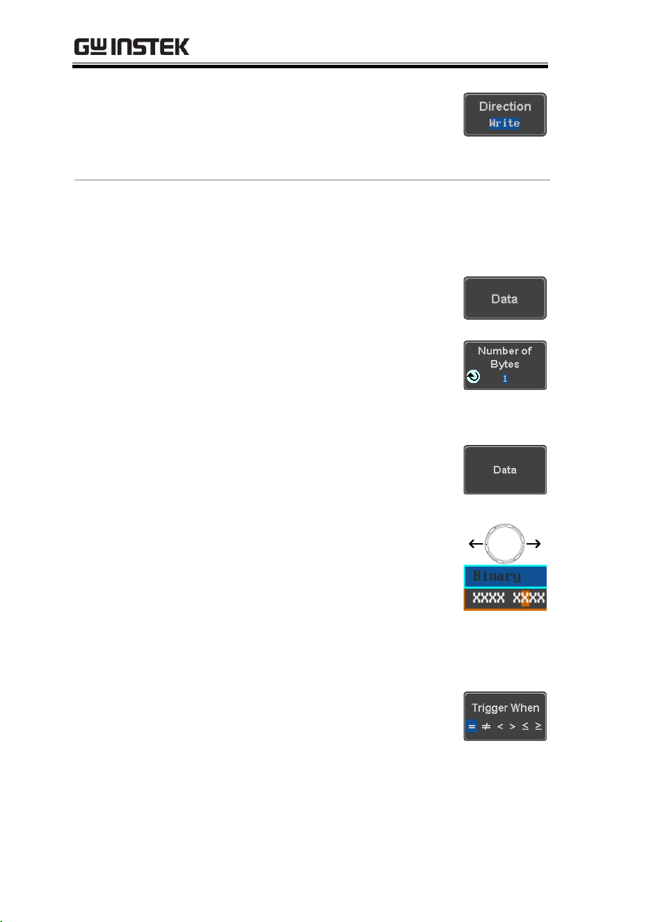
MDO-2000E series User Manual
174
9. Press Direction on the bottom
menu and select the CAN
Direction from the side menu.
CAN Direction
Write, Read, Read or Write
Trigger On - Data
If Data/Id and Data was configured for the
Trigger On setting, then the triggering data
must be configured.
10. Press Data on the bottom menu.
11. Press Number of Bytes from the side
menu and choose the number of
bytes for the data.
Bytes
1~8 Bytes
12. Press Data from the side menu to
edit the triggering data.
To edit the data, use the Variable
knob to highlight a binary or hex
digit and press Select. Use the
Variable knob to choose a value for
the digit and press Select to
confirm.
VARIABLE
Binary
0,1,X (don’t care)
Hex
0~F, X (don’t care)
13. Press Trigger When from the side
menu to choose the triggering
condition for the data.
When
=, ≠, <, >, ≤, ≥
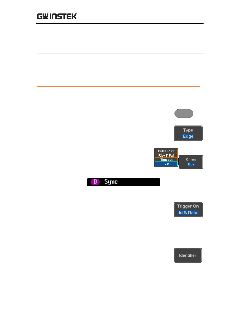
ADVANCED CONFIGURATION
175
14. The oscilloscope will now trigger when the
specified bus data matches the Trigger When
conditions.
LIN Bus Trigger
The LIN bus trigger conditions can be set at any time after the bus
setting has been set to LIN.
Panel Operation
1. Set the Bus to LIN in the bus menu.
Page 129
2. Press the Trigger Menu key.
Menu
3. Press Type from the bottom menu.
4. Select Others → Bus from
the side menu. The Bus
indicator appears at the
bottom of the display.
From left: Bus trigger, Trigger source
5. Press Trigger On and select the
triggering condition for the
selected bus.
Trigger On
Sync, Identifier, Data, Id and Data,
Wakeup Frame, Sleep Frame, Error.
Trigger On –
Identifier
6. If Identifier or Id & Data was
configured for the Trigger On
setting, press Identifier from the
bottom menu.
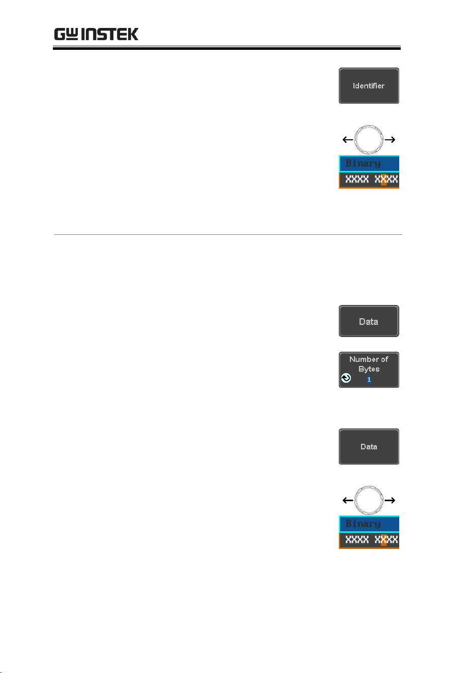
MDO-2000E series User Manual
176
7. Press Identifier from the side menu
to set the identifier data.
To edit the identifier, use the
Variable knob to highlight a binary
or hex digit and press Select. Use
the Variable knob to choose a value
for the digit and press Select to
confirm.
VARIABLE
Binary
0,1,X (don’t care)
Hex
0~F, X (don’t care)
Trigger On - Data
If Data/Id and Data was configured for the
Trigger On setting, then the triggering data
must be configured.
8. Press Data on the bottom menu.
9. Press Number of Bytes from the side
menu and choose the number of
bytes for the data.
Bytes
1~8 Bytes
10. Press Data from the side menu to
edit the triggering data.
To edit the data, use the Variable
knob to highlight a binary or hex
digit and press Select. Use the
Variable knob to choose a value for
the digit and press Select to
confirm.
VARIABLE
Binary
0,1,X (don’t care)
Hex
0~F, X (don’t care)
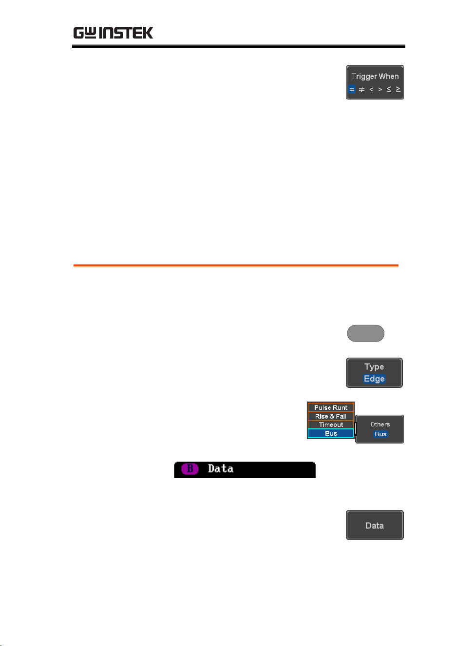
ADVANCED CONFIGURATION
177
11. Press Trigger When from the side
menu to choose the triggering
condition for the data.
When
=, ≠, <, >, ≤, ≥
12. The oscilloscope will now trigger when the
specified bus data matches the Trigger When
conditions.
Parallel Bus Trigger
The parallel bus trigger conditions can be set at any time after the
bus setting has been set to parallel. The parallel bus can be set up to
trigger on a specified data pattern.
Panel Operation
1. Set the Bus to parallel in the bus
menu.
2. Press the Trigger Menu key.
Menu
3. Press Type from the bottom menu.
4. Select Others → Bus from
the side menu. The Bus
indicator appears at the
bottom of the display.
From left: Bus trigger, Data source
5. Press Data from the bottom menu.

MDO-2000E series User Manual
178
6. Press Data from the side menu to
edit the triggering data.
To edit the data, use the Variable
knob to highlight a binary or hex
digit and press Select. Use the
Variable knob to choose a value for
the digit and press Select to
confirm.
VARIABLE
Binary
0,1,X (don’t care)
Hex
0~F, X (don’t care)
7. The oscilloscope will now trigger when the
specified data appears on the bus.
Using the Logic Trigger
Background
The digital channels can be set up to trigger on
specified logic levels and for a specified clock
edge.
For example the digital channels can be set to
trigger on the rising edge of a clock signal when bit
1 of a digital channel is high and all other channels
are ignored.
Panel Operation
1. Press the Trigger Menu key.
Menu
2. Press Type from the bottom menu.
3. Select Others → Logic from
the side menu. The Logic
indicator appears at the
bottom of the display
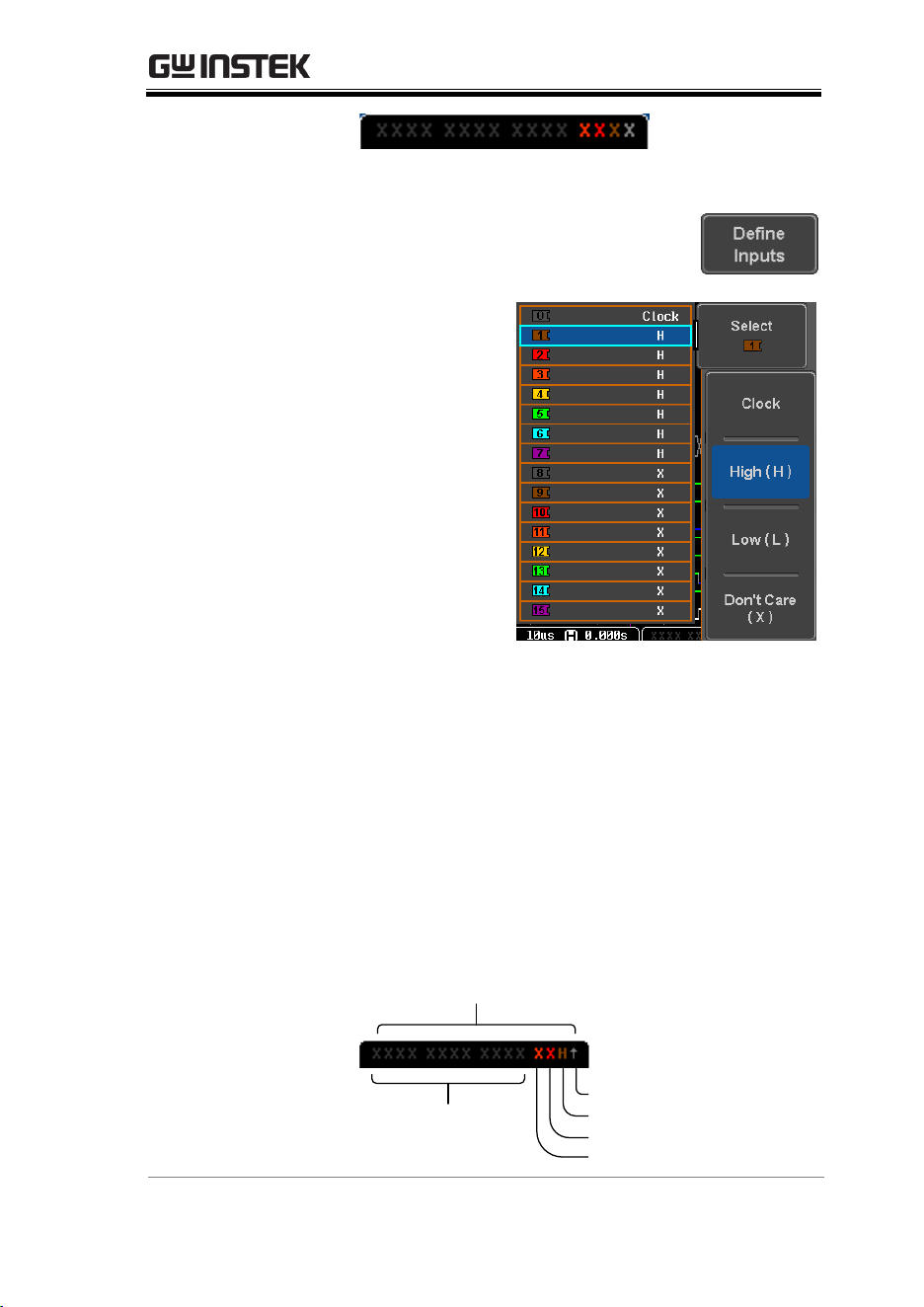
ADVANCED CONFIGURATION
179
From left: Bits D15~D0
4. Press Define inputs from the
bottom menu.
5. Press Select on
the side menu
and select a
channel.
6. Next, select a
logic level for
the selected
channel, or set
the selected
channel as the
clock signal.
Logic
Clock, High (H), Low (L), Don’t
Care (X)
7. Repeat steps 5 to 6 for the remaining channels.
8. The chosen logic levels will be reflected in the
trigger indicator at the bottom of the screen.
The color of each channel, if active will also be
displayed. If a channel is not turned on, it will
be grayed-out (see page 200 to turn the digital
channels on or off in the Logic Analyzer menu).
Example
D15 ~ D0
D0 clock edge
D1 = High
D2 = don’t care
D3 = don’t care
D15 ~ D4 = turned off
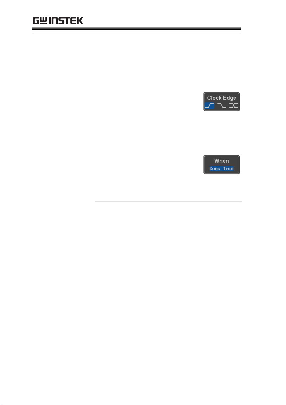
MDO-2000E series User Manual
180
Logic Trigger
Timing
If a channel was selected as a clock signal, then the
clock edge determines when the logic comparison
is made. If a clock was not defined then the When
menu determines the triggering timing conditions.
This is described below in step 9 and 10.
9. If a clock signal was defined, press
Clock Edge from the bottom menu
and select a clock transition. At
each clock transition a comparison
will be made.
Clock Edge
Rising, Falling, Either
10. If no clock were defined, press
When from the bottom menu and
choose the trigger timing
conditions.
Trigger When
Description
Goes True
Triggers when the defined logic
goes true (rising edge).
Goes False
Triggers when the defined logic
goes false (falling edge).
Is True >
10.0ns ~ 9.99s. Triggers when
the defined logic is true for
greater than the defined
amount of time (falling edge).
Is True <
10.0ns ~ 9.99s. Triggers when
the defined logic is true for less
than the defined amount of
time (falling edge).
Is True =
10.0ns ~ 9.99s. Triggers when
the defined logic is true for the
defined amount of time ±5%
(falling edge).
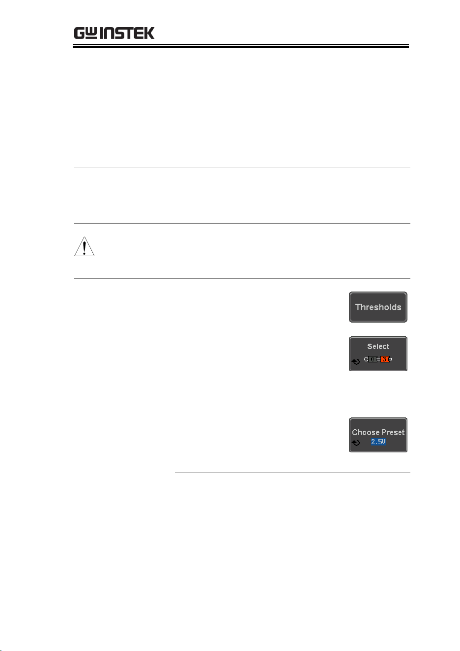
ADVANCED CONFIGURATION
181
Is True ≠
10.0ns ~ 9.99s. Triggers when
the defined logic is not true for
the defined amount of time ±5%
(falling edge).
11. The oscilloscope will now trigger when the
specified logic appears among the digital
channels.
Trigger Threshold
Levels
The trigger threshold levels for the digital channels
can be assigned from a selected number of preset
levels or a user-defined threshold level.
Note
The threshold levels that are set in this menu will
replace the threshold levels that are set in the Logic
Analyzer menu (page 207).
12. Press Thresholds from the bottom
menu.
13. Press Select from the side menu
and choose a group of channels.
Group
D0~D3, D4~D7, D8~D11,
D12~D15
14. Press Choose Preset to select a pre-
set logic threshold.
Logic Type
Threshold
TTL
1.4V
5.0V CMOS
2.5V
3.3V CMOS
1.65V
2.5V CMOS
1.25V
ECL
-1.3V
PECL
3.7V

MDO-2000E series User Manual
182
0V
0V
15. Press Threshold to set a user
defined threshold.
Range
± 5.00V
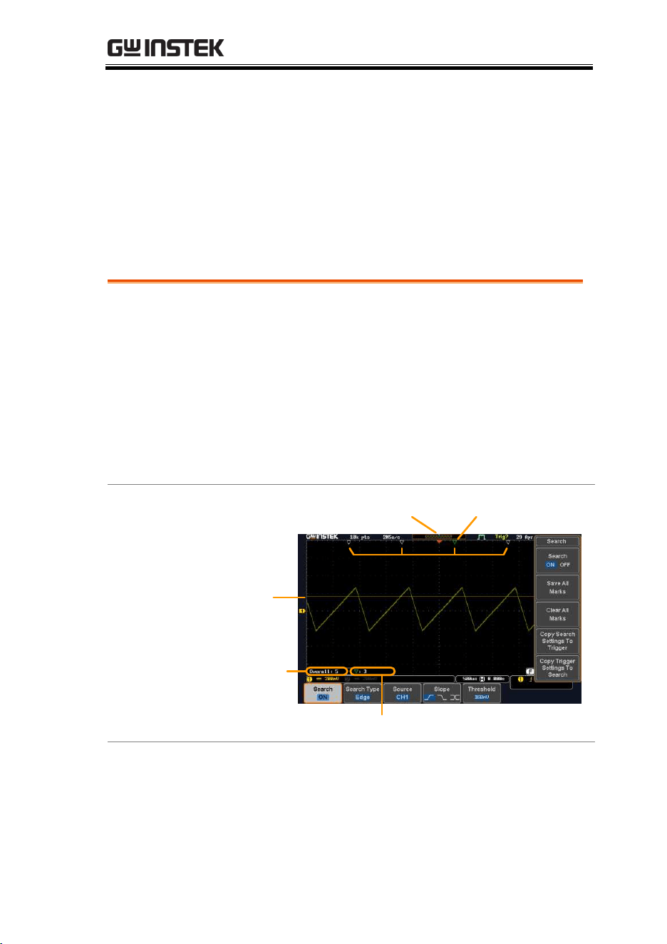
ADVANCED CONFIGURATION
183
Search
The search feature can be used to search for events on the analog
and digital input channels. The events that can be searched for are
similar to the events that are used for the trigger system. The only
difference is that the search feature uses the measurement
threshold levels rather than the trigger level to determine events.
Configuring Search Events
Background
Similar to configuring the trigger system, the
Search events must first be configured before they
can be found.
Luckily the trigger system configuration settings
can also be used for the search events. The types of
searches are listed below. Please note that a full
description of the events can be found in the
Trigger section on page 143.
Display
Bus
Total
number
of events
Trigger point
Digital signals
Current marker
Search event markers
Current marker position
Level for
event
search
Search Event
Types
Edge, Pulse Width, Runt, Rise and Fall Time, FFT
Peak*, Logic and Bus
*The FFT Peak search event doesn’t have a trigger
equivalent.
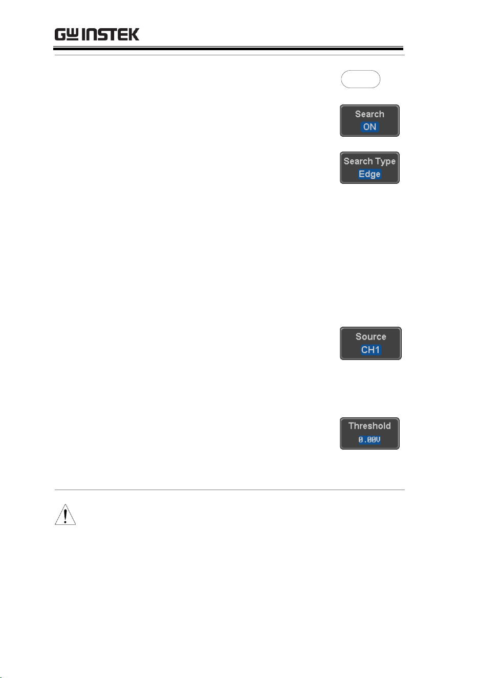
MDO-2000E series User Manual
184
Panel Operation
1. Press the Search menu key.
Search
2. Press Search from the bottom menu
and turn the Search function on.
3. Press Search Type from the bottom
menu and select the type of search.
The search events are configured
in the same fashion as the trigger
events.
Please see the trigger configuration settings for
details:
Event
Types:
Edge, Pulse Width, Runt, Rise/Fall
Time, FFT Peak*, Bus
*No trigger equivalent.
4. Select the source from which to
search events. Press Source from
the bottom menu, and select the
source.
Sources:
CH1 ~ CH4, Math, D0 ~ D15
5. To set the threshold levels for the
search events (instead of the
trigger level that is used for trigger
events), use the threshold soft-key
from the bottom menu.
Note
The search function can support up to 10,000 events,
however only 1,000 events can be displayed on screen
at once.

ADVANCED CONFIGURATION
185
Copying Search Event To/From Trigger Events
Background
As the trigger system and search feature have
similar settings, their settings can be used
interchangeably by using the Copy functions.
Interchangeable
Settings
Edge, Pulse Width, Pulse Runt, Rise and Fall Times,
Logic and Bus (FFT Peak has no trigger equivalent)
Panel Operation
1. Press Search from the lower bezel
menu.
2. To copy the settings of the selected
search type to the trigger settings,
select Copy Search Settings to
Trigger.
3. To copy over the current trigger
settings to the search settings,
press Copy Trigger Settings To
Search.
Note
If the settings cannot be copied or if there are no
trigger settings configured (so that you cannot copy
from the trigger settings), then those particular
options will not be available.
Search Event Navigation
Background
When using the search feature, each event can be
searched according to the event settings.
Operation
1. Turn Search on and set the
appropriate search type.
Page 183
2. Search events are marked by hollow white
triangles at the top of the graticule.
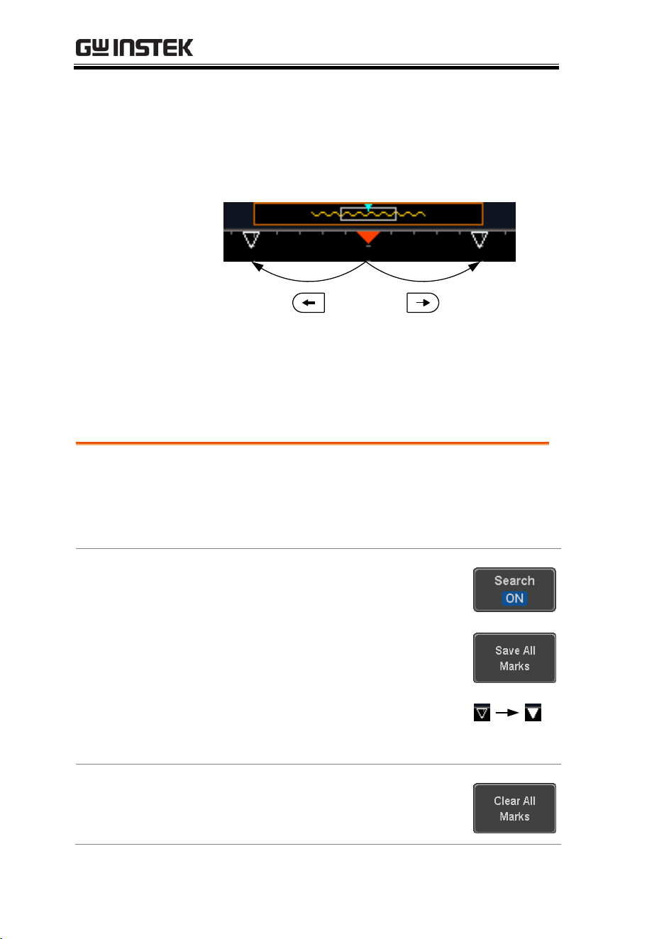
MDO-2000E series User Manual
186
3. Use the search arrow keys to move between
each search event.
Search events can be navigated in both stop and
run mode.
When using the arrow keys to navigate to each
event, the “current event” will always be
centered on the display.
Save Search Marks
Background
The search events can be saved to the graticule
display, allowing you to superimpose new search
events. Search events are saved over the entire
record length, with a maximum of 1000 marks.
Save Marks
1. Press Search from the lower bezel
menu.
2. Press the Save All Marks soft-key.
3. The search event markers will
become solid white triangles to
indicate that they have been saved.
Clear All Marks
To clear all the saved marks, press
Clear All Marks from the side
menu.
ADVANCED CONFIGURATION
187
Note
Each time the Save All Marks function is used, the
previously saved marks will also be retained,
unless cleared.
Setting/Clearing Single Search Events
Background
In addition to searching for search events based on
Search Type settings, custom search marks can be
created with the Set/Clear key.
Set Search Event
1. Navigate to a point of interest using
the horizontal position knob or
some other method.
POSITION
PUSH TO
ZERO
2. Press the Set/Clear key.
Set/Clear
3. A marker will be saved at the center
of the display.
This marker can be navigated
to/from in the same way that a
normally saved search marker
can.
Clear Search Event
To clear a set search event, use the
search arrows to navigate to the
event of interest and press the
Set/Clear key.
The marker will be deleted from the
display.
Set/Clear
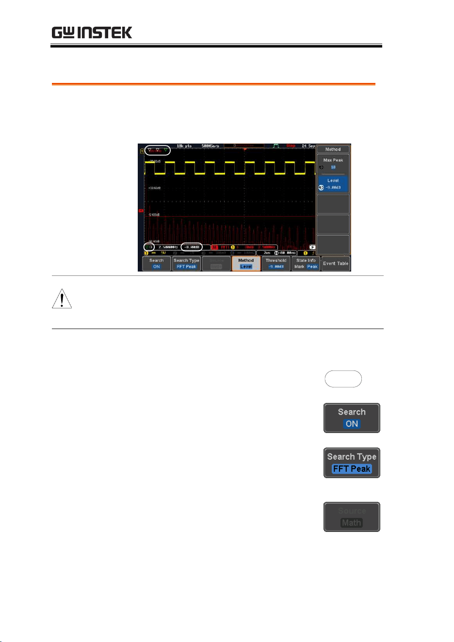
MDO-2000E series User Manual
188
FFT Peak
Background
The FFT Peak search type can be used to mark all
FFT peaks that are above a certain threshold.
Number of events
or peak amplitude
Search events
Threshold level
Note
The search function can support up to 10,000 events,
however only 1,000 events can be displayed on screen
at once.
Panel Operation
1. Turn the FFT math function on.
Page 69
2. Press the Search menu key.
Search
3. Press Search from the bottom menu
and turn the Search function on.
4. Press Search Type from the bottom
menu and select FFT Peak from the
side menu.
5. Note that the Math source is
automatically selected.
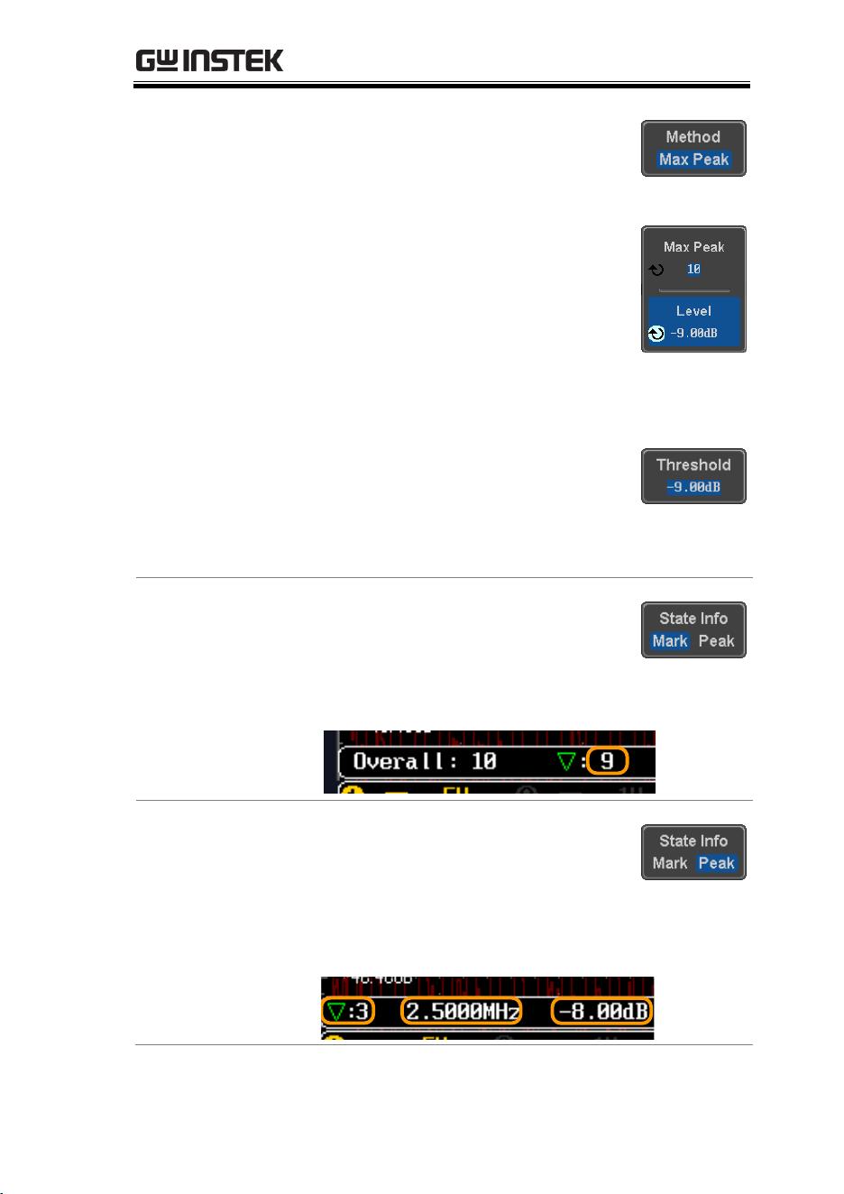
ADVANCED CONFIGURATION
189
6. Next, select the event search
method by pressing Method from
the bottom menu.
Select Max Peak to search by a
selected number of “max” peaks.
Select Level to set the threshold
level for the search events. Any
peaks above the threshold level
will be seen as a search event.
The threshold level will be
mirrored in the Threshold key.
Max Peak
1 ~ 10
Level
-100db ~ 100dB
View Number of
Peak Events
To view the number of peak
events, set State Info to Mark. The
number of search events will be
shown at the bottom of the screen.
View Amplitude
of Peak Search
Event
To view the position and
amplitude of a selected event, set
State Info to Peak. This information
will be shown at the bottom of the
display.
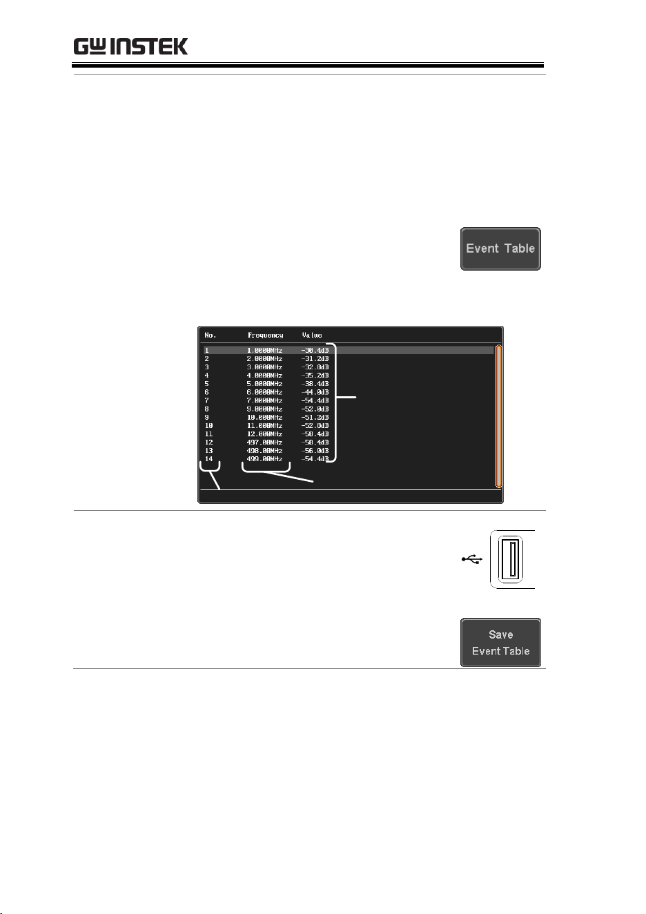
MDO-2000E series User Manual
190
Peak Event Table
The Event Table function tabulates the amplitude
and frequency of each peak event in real time. The
event table can also be saved to a USB disk drive.
File names are saved as a PeakEventTbXXXX.csv,
where XXXX is a number starting from 0001 and is
incremented each time the event table is saved.
7. Press Event Table from the bottom
menu and turn the Event Table
function on.
The event table will appear on the screen.
Peak frequency
Peak number
Amplitude
Save Event Table
8. To save the event table, insert a
USB memory drive into the front
panel USB-A port.
9. Press Save Event Table. The event
table will be saved as
PeakEventTbXXXX.csv.
2V

ADVANCED CONFIGURATION
191
Event Table CSV
Format
The format for the CSV file is the same as the event
table displayed on the MDO-2000E SERIES screen;
No., Frequency, and Value.
For example:
No.
Frequency
Value
1
1.0000MHz
-29.6dB
2
2.0000MHz
-30.4dB
3
3.0000MHz
-32.0dB
Center Peak
Results on Screen
To shift the peak events to the
center of the screen, press Selected
Peak To Center from the event table
side menu.
MDO-2000E series User Manual
192
System Settings and Miscellaneous Settings
This section describes how to set the interface, language, time/date,
probe compensation signal, erase the internal memory and access
useful QR codes.
Select Menu Language
Description
The MDO-2000E SERIES has a number of different
languages to choose from.
Panel Operation
1. Press the Utility key.
Utility
2. Press Language on the lower menu.
3. Select the language* from the side menu.
*Language selection may differ based on
region, and as such are not listed here.
View System Information
Panel Operation
1. Press the Utility key.
Utility
2. Press System from the lower menu.
3. Press System Info from the side
menu. A display panel will appear
showing:
Manufacturer name
Model name
Serial number
Firmware version
Manufacturer URL
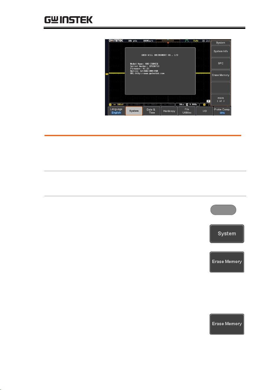
ADVANCED CONFIGURATION
193
Erase Memory
Background
The Erase Memory function will erase all internal
waveforms, setup files and labels from internal
memory.
Erased Items
Waveform 1~20, Setting memory 1~20, Reference
1~4, Labels
Panel Operation
1. Press the Utility key.
Utility
2. Press System from the lower menu.
3. Press Erase Memory from the side
menu.
A message will prompt you to press Erase
Memory again to confirm the process. Pressing
any other key will cancel erasing the memory.
4. Press Erase Memory again.
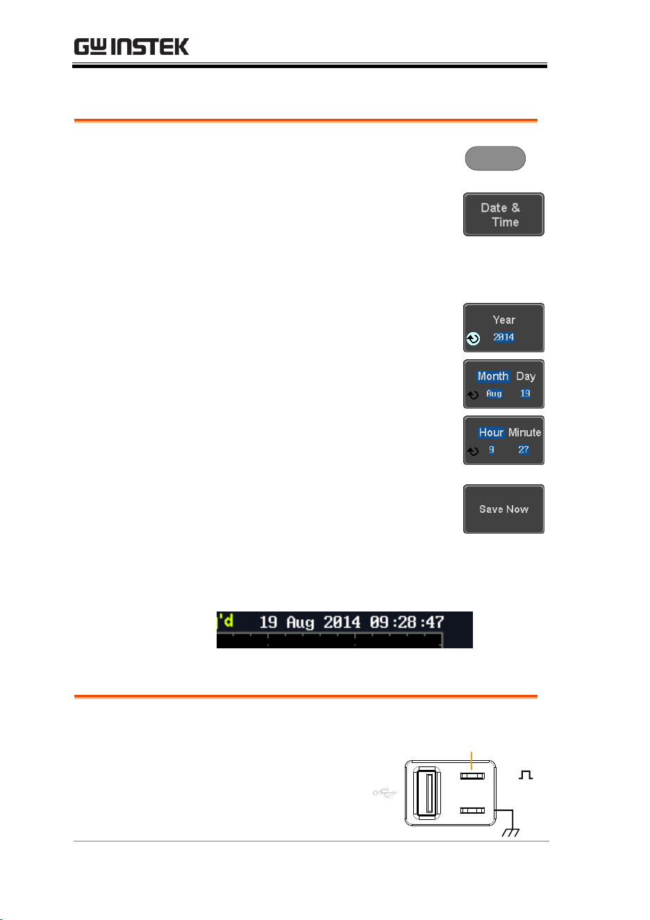
MDO-2000E series User Manual
194
Set Date and Time
Panel Operation/
Parameter
1. Press the Utility key.
Utility
2. Press Date & Time on the lower
menu.
3. Set the Year, Month, Day, Hour and Minute from
the side menu.
Year
2000 ~ 2037
Month
1 ~ 12
Day
1 ~ 31
Hour
1~23
Minute
0~59
4. Press Save Now from the side menu
to save the date and time.
5. Make sure the date/time setting is correctly
reflected at the top of the display.
Probe Compensation Frequency
Background
The probe compensation
output can be set from
1kHz (default) to
200kHz, in steps of
1kHz.
2V
Compensation
output
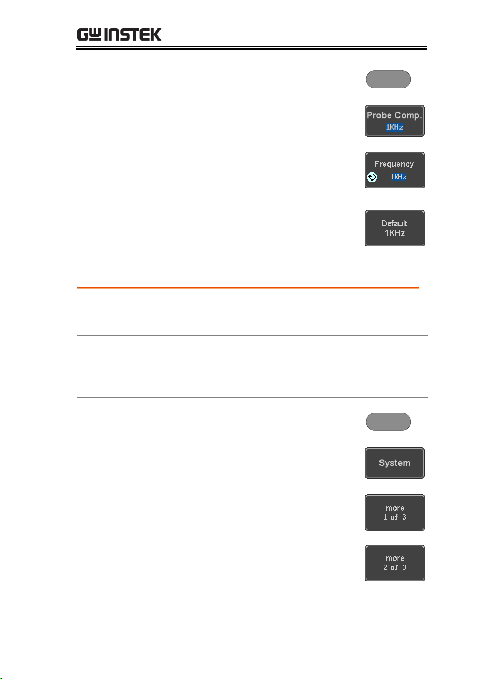
ADVANCED CONFIGURATION
195
Panel Operation/
Parameter
1. Press the Utility key.
Utility
2. Press Probe Comp. on the lower
menu.
3. Press Frequency and change the
frequency of the probe
compensation signal.
Default Frequency
4. Press Default to set the frequency
of the probe compensation signal
to 1kHz default.
QR Code Reader Function
Background
The QR Code reader function displays a number of
preset QR codes that link to useful websites.
QR Code Items
GW Instek website
GW Instek contact window (marketing
department)
Panel Operation/
Parameter
1. Press the Utility key.
Utility
2. Press System from the lower menu.
3. Press More 1 of 3, More 2 of 3 from
the side menu.
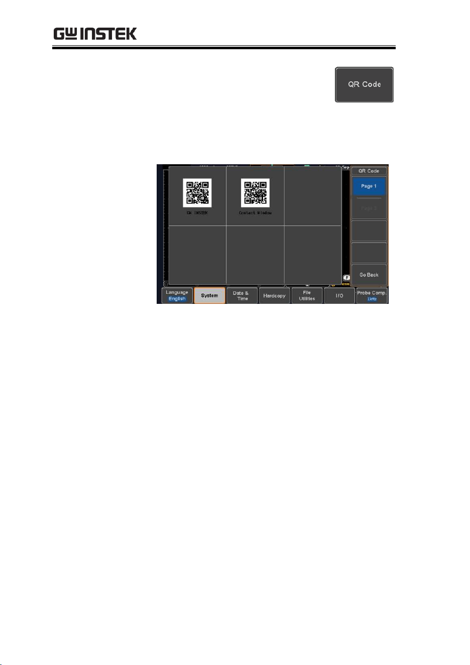
MDO-2000E series User Manual
196
4. Press QR Code from the side menu.
There will be two pages of QR
codes to choose from.
Press Page 1 or Page 2 to navigate
to each page.
5. Use a QR code reader app on your smart phone
or tablet to read one of the QR codes.

LOGIC ANALYZER
197
LOGIC ANALYZER
Logic Analyzer Operation ..........................................198
Overview ................................................................................................ 198
Using the Logic Analyzer Probes ...................................................... 198
Digital Display Overview .................................................................... 199
Activating Digital Channels ................................................................ 200
Activate Digital Channels as a Group ..................................... 200
Activate Individual Channels .................................................... 201
Moving the Digital Channels or Creating
Digital Channel Groups ............................................................ 203
Digital Channel Vertical Scale ............................................................ 207
Digital Channel Threshold Levels ..................................................... 207
Analog Waveform ................................................................................ 208
Adding Labels to Digital Channels or the Analog Waveform ..... 209

MDO-2000E series User Manual
198
Logic Analyzer Operation
Overview
Background
The logic analyzer inputs can be used to measure
discrete inputs or can be used to measure values
on a parallel or serial bus.
The logic analyzer has a sample rate of 1GSa/s
with a bandwidth of 200MHz.
Supported Logic
Thresholds
TTL, CMOS,
ECL, PELC,
User- defined
The MDO-2000E supports
common logic thresholds and
supports user-defined thresholds
of ± 5V if the in-built threshold
levels are unsuitable.
Digital Trigger
Types
Edge, Pulse
Width, Timeout,
Bus, Logic
As standard, the digital channels
support basic edge, pulse width,
timeout as well as bus and logic
triggers.
Using the Logic Analyzer Probes
Background
This section will describe how to connect the
digital channels to the device under test.
Connection
1. Turn the DUT off to protect it from being short
circuited when the probes are attached.
2. Insert the Logic
Analyzer probe
(GTL-16E) into the
Logic Analyzer slot
input.
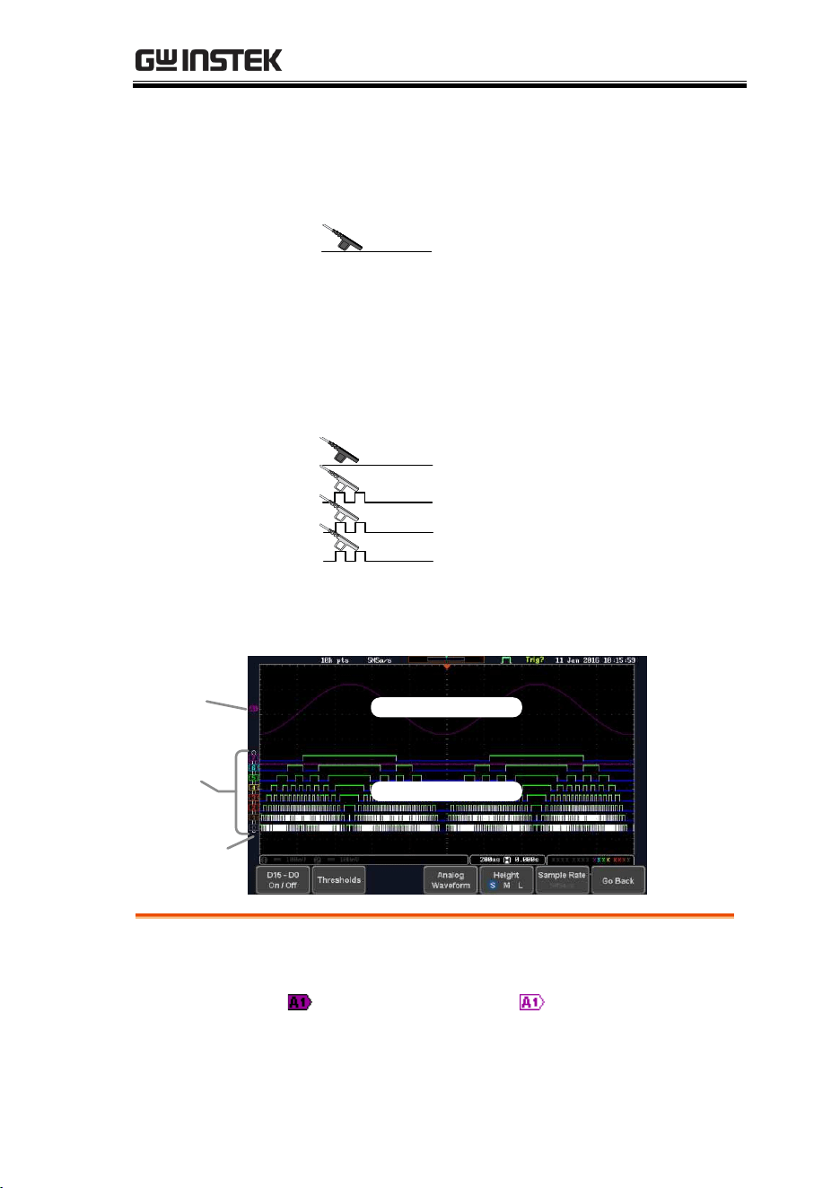
LOGIC ANALYZER
199
3. Connect the ground lead from the logic
analyzer probe (marked G) to the circuit
ground on the DUT.
GND
G
4. Connect another probe lead to a point of
interest on the circuit. Make note of which
probe lead is connected to which point.
5. Repeat step 4 with any remaining probes.
Signal 2
Signal 3
GND
Signal 1
1
2
G
3
….
Digital Display Overview
Analog
waveform
indicator
Digital
channel
indicators
Digital waveforms
Analog waveform
Digital
channel
group
Analog Waveform
Indicator
Used to show the position of the analog waveform
outputs.
Currently active
analog waveform (solid
indicator)
Activated analog
waveform (transparent
indicator)
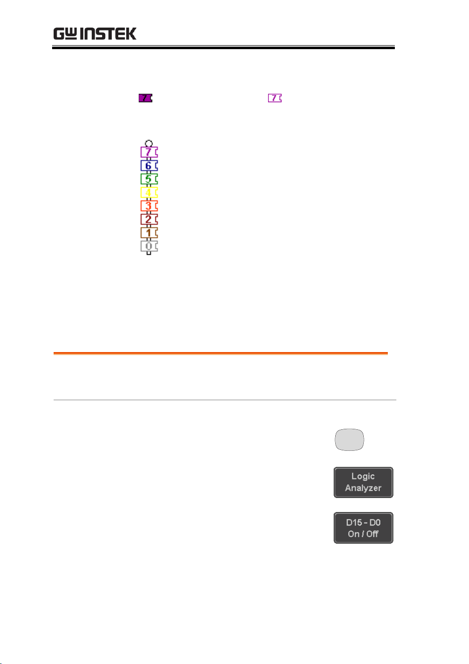
MDO-2000E series User Manual
200
Digital Channel
Indicators
Used to show the position and grouping of the
digital channels.
Currently active
digital channel (solid
indicator)
Activated digital
channel (transparent
indicator)
Digital Channel
Group (Pinned)
When digital channels are grouped together,
they are shown as being pinned together.
When grouped, digital channels can be
moved as a single group.
Activating Digital Channels
The digital channels can be initially turned on in groups of 8 or
individually.
Activate Digital Channels as a Group
Background
The digital channels can be turned on or off in
groups of eight, D0~D7 and D8~D15.
Panel Operation
1. Press the Option key.
Option
2. Press Logic Analyzer from the
bottom menu.
3. Press D15 – D0 On/Off key.
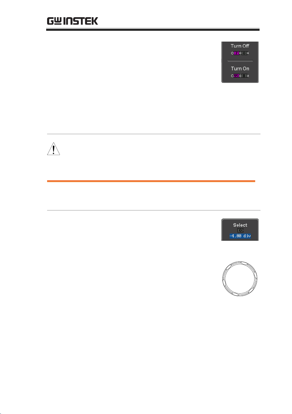
LOGIC ANALYZER
201
4. Select which group of digital
inputs you want turned on or off
from the side menu.
Group1
D0~D7
Group2
D8~D15
5. The digital channels will appear on the
graticule.
Note
When all the digital channels are turned on, they
will appear as a single group.
Activate Individual Channels
Background
Each digital channel or group can be turned on or
off individually.
Panel Operation
1. Press the Select soft-key.
2. Use the variable knob to highlight
a channel or a group.
VARIABLE
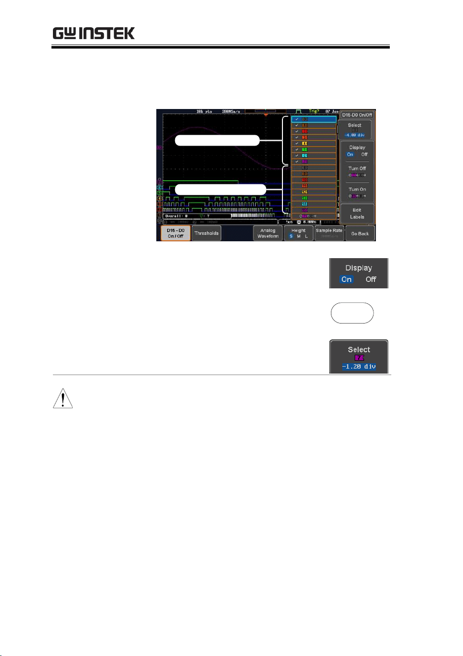
MDO-2000E series User Manual
202
3. A 'tick' next to a particular channel or group
indicates that the channel or group is currently
on.
Channel 0~7 is on
Channel 8~15 is off
4. Press the Display soft-key or the
Select key to toggle the selected
channel or group on or off.
or
Select
5. Press the Select soft-key again to
reduce the menu.
Note
Channels can also be selected just by turning the
variable knob when the mode is set to LA move mode.
In this mode the selected channel or group will be
shown on the Select soft-key. However this method
will only show those channels/groups that have
already been turned on. See below for details.
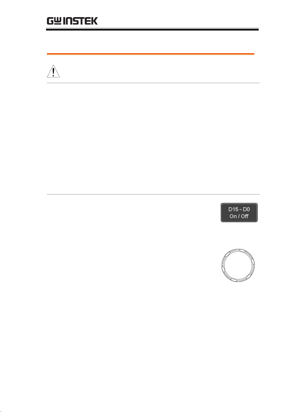
LOGIC ANALYZER
203
Moving the Digital Channels or Creating Digital Channel Groups
Note
The digital channels must first be activated. See
page 200.
Background
The logic analyzer has two basic modes of
operation for selecting or moving digital channels.
LA Select mode: This mode is used to select digital
channels that have already been activated.
LA Move mode: This mode is used to move the
vertical position of the digital channels and to
group digital channels into groups.
The Select key is used to toggle between both
modes when in the D15~D0 On/Off menu.
Panel Operation
1. Press the D15~D0 On/Off key. The
scope will initially be in 'LA Select
mode'.
2. Use the variable knob to choose a
channel or group. The selected
channel/group will be shown on
the Select key. Only channels that
have been activated can be selected
this way.
VARIABLE
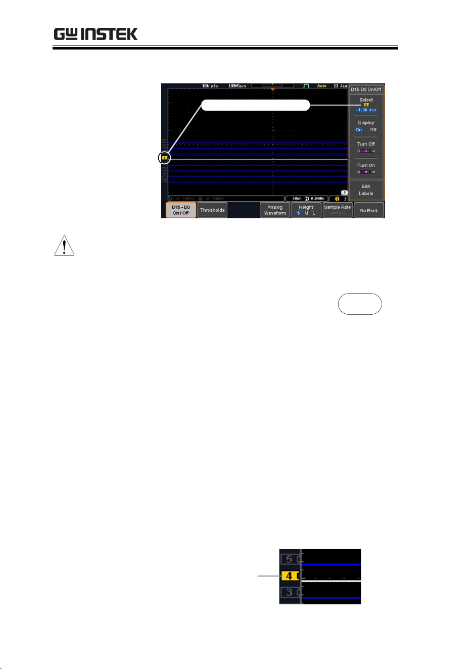
MDO-2000E series User Manual
204
Below, channel 4 is selected.
Channel 4 is selected
Note
If the Variable knob cannot select a channel, press
the Select key to toggle the scope into “LA Select
mode”.
3. Press the Select key. The mode
toggles from “LA Select mode” to
'LA Move mode'.
A message will indicate which
mode is currently active.
Select
The Move mode is used to move the digital
channel position on the graticule as well as to
group the channels. If you turned on all the
digital channels, you will notice that they are
already grouped as a single group.
You can tell when it is in move mode as the
selected channel/group flashes and the labels
for the other channels/groups become grayed
out.
Channel 4 is in the
“Move” mode and
the labels for the
other channels are
grayed out
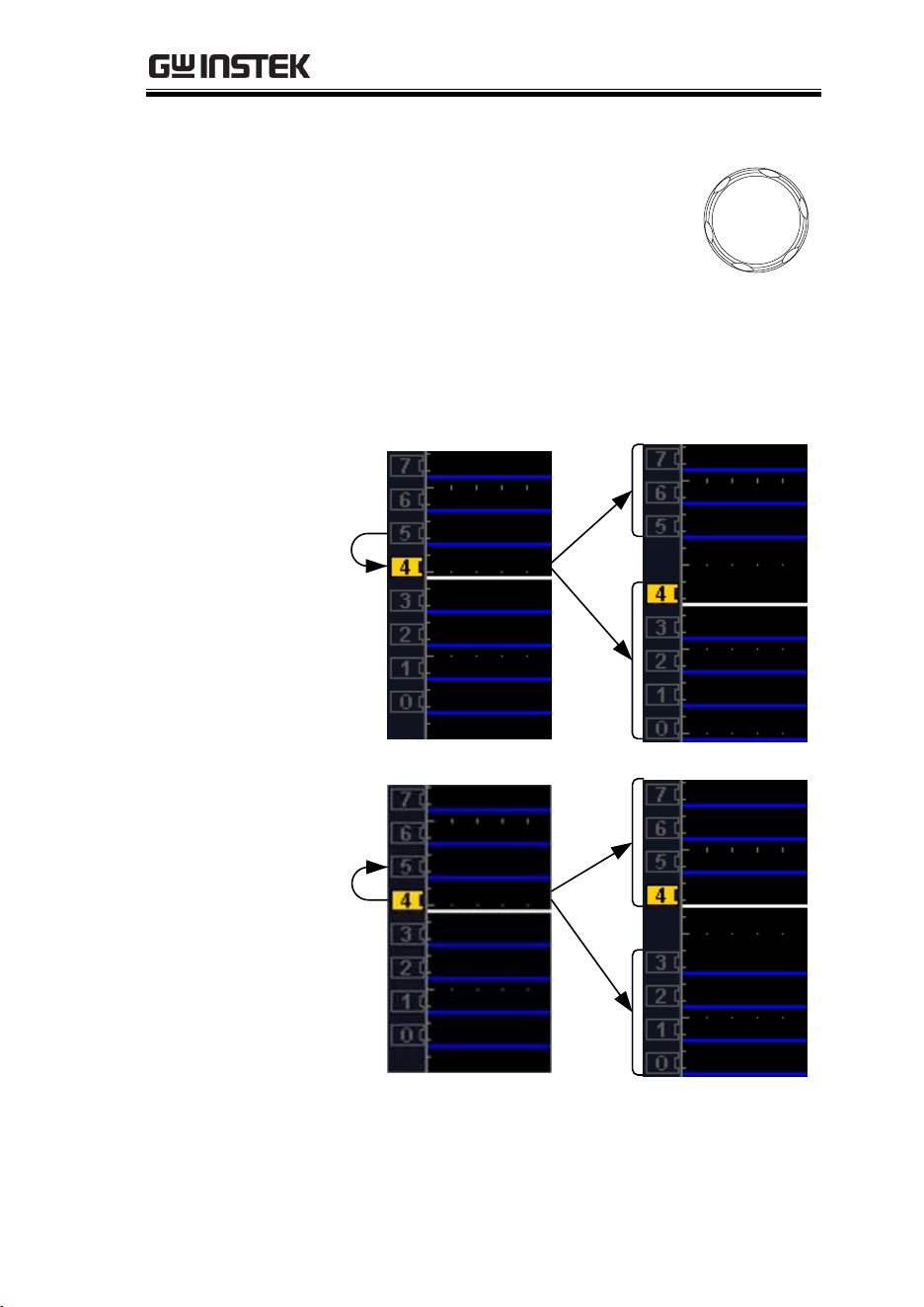
LOGIC ANALYZER
205
4. Use the variable knob to position
the selected channel/group:
VARIABLE
If you position the channel indicator over the
next/previous channel, it will split the group
into 2.
Split the group above the selected channel:
Split the group below the selected channel:
If you continue to move the channel indicator
past the next/previous channel, it will move the
indicator anywhere within that group.
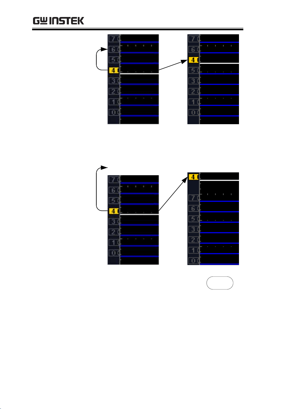
MDO-2000E series User Manual
206
5. If you move the indicator outside of the group,
it will remove the selected channel from the
group.
6. Press the Select key again. This will
return you to the LA Select mode.
You can tell when it is in the Select
mode as no channel will be grayed
out.
Select
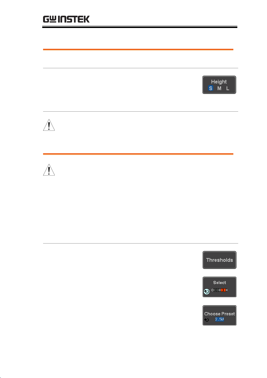
LOGIC ANALYZER
207
Digital Channel Vertical Scale
Background
The digital channels have 3 preset scales, S, M, L.
Panel Operation
1. From the bottom menu, press
Height to toggle the vertical scale of
the digital channels.
Height
S, M, L
Note
If more than 8 digital channels are active, the large (L)
option will be disabled.
Digital Channel Threshold Levels
Note
Threshold levels can be set to four groups of
digital channels: D0~D3, D4~7, D8~D11 and
D12~D15. Each group can have a different
threshold level.
The MDO-2000E has 7 preset threshold levels and
a user-defined threshold. A user-defined threshold
level can be set for each group. Any signal over the
threshold level corresponds to a high (1); any
signal under the threshold level is a low (0).
Panel Operation
1. From the bottom menu, press the
Thresholds soft-key.
2. Press Select from the side menu
and choose a group of channels.
3. Press Choose Preset to select a pre-
set logic threshold.
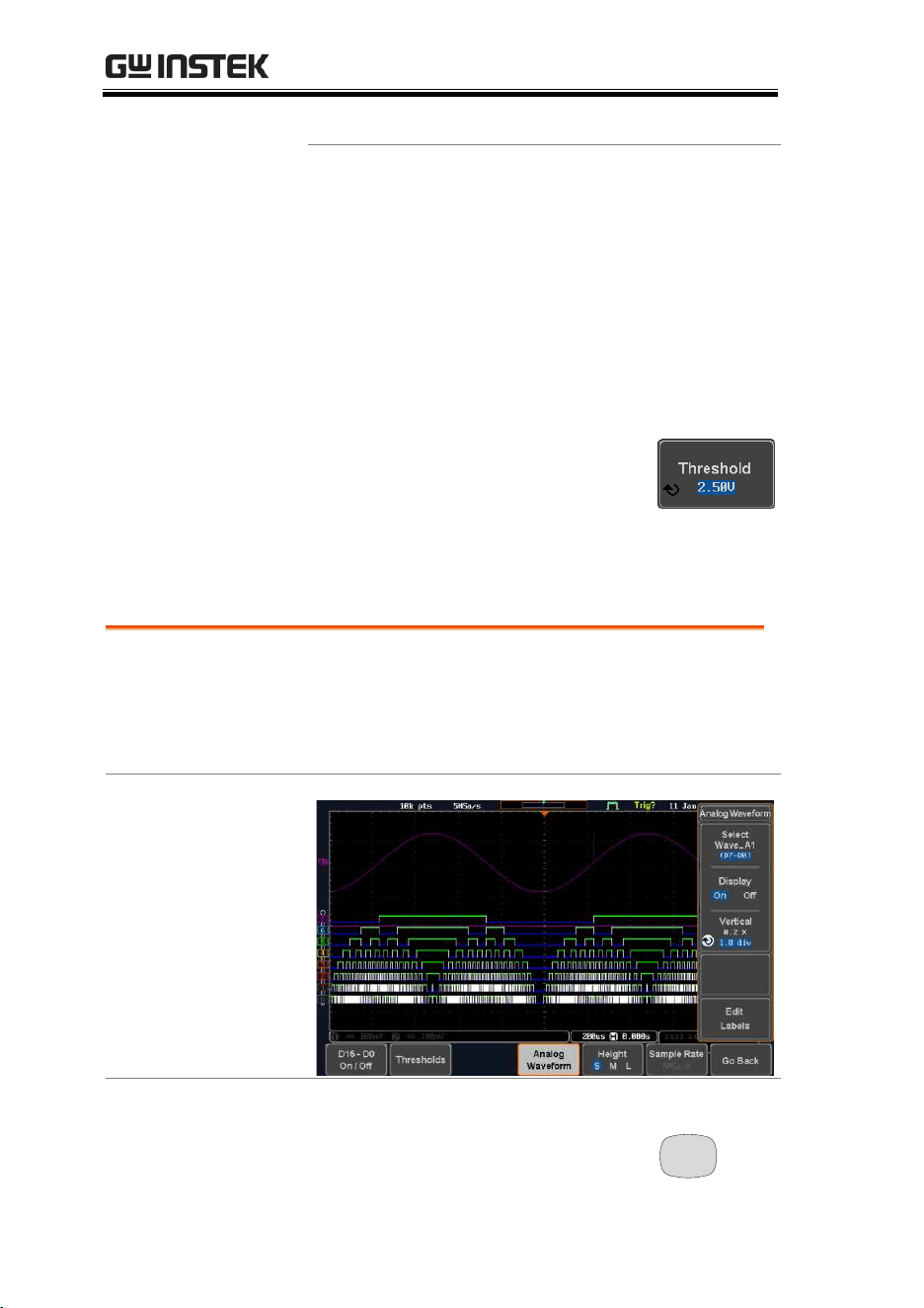
MDO-2000E series User Manual
208
Logic Type
Threshold
TTL
1.4V
5.0V CMOS
2.5V
3.3V CMOS
1.65V
2.5V CMOS
1.25V
ECL
-1.3V
PECL
3.7V
0V
0V
4. Press Threshold to set a user
defined threshold for the currently
selected group.
Range
±5V
Analog Waveform
Background
The analog waveform function combines the
digital channel inputs into two 8-bit analog
waveforms. The analog waveforms are created
from the digital channel groups D0~7 and D8~15.
Example
Panel Operation
1. Press the Option key.
Option
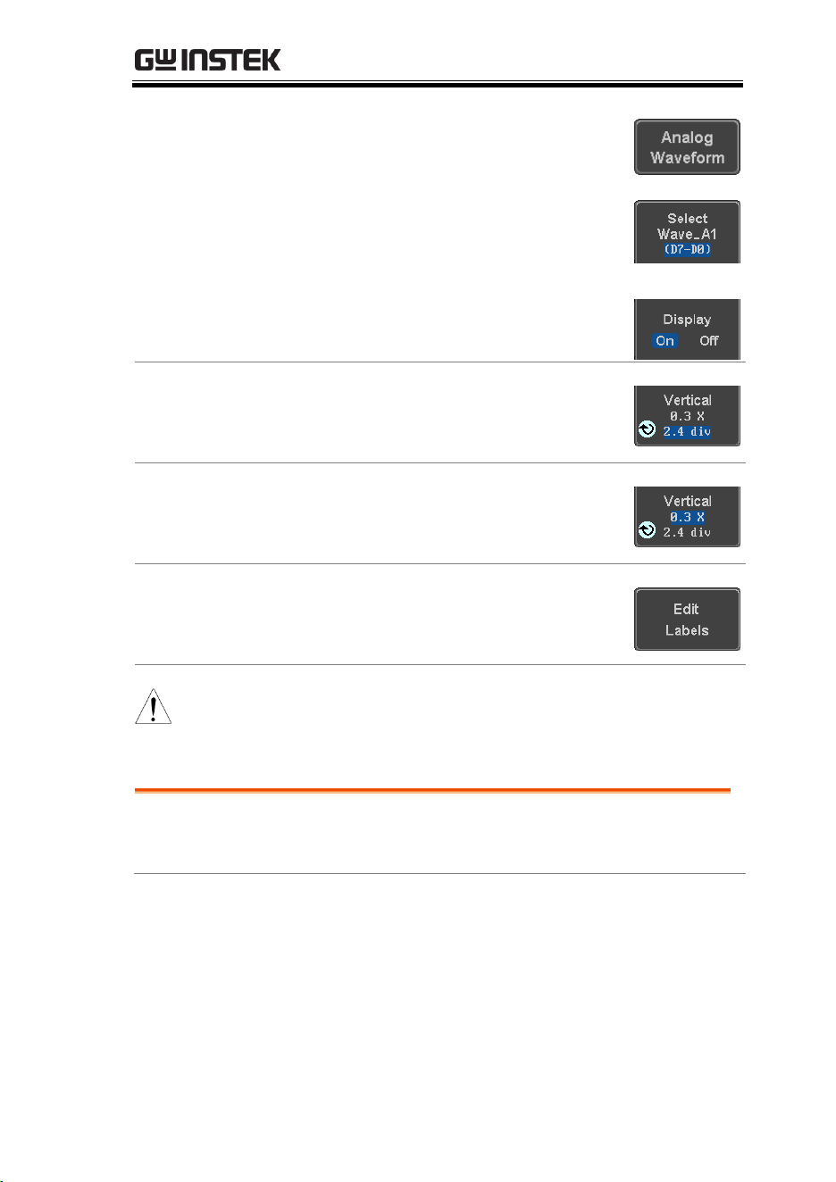
LOGIC ANALYZER
209
2. Press the Analog Waveform key.
3. Press Select and choose between
Wave_A1 (D7~D0) or Wave_A2
(D15~D8).
Display on Screen
4. Press Display to display the
selected waveforms on the screen.
Set Vertical
Position
5. Press Vertical until the div
parameter is highlighted. Use the
Variable knob to set the position.
Set Vertical Scale
6. Press Vertical until the X scale
parameter is highlighted. Use the
Variable knob to set the scale.
Edit Labels
7. Press Edit Labels to edit the label
for the currently selected analog
waveform. See below for details.
Note
Only one analog waveform can be displayed at a time.
Adding Labels to Digital Channels or the Analog Waveform
Background
Digital labels can be added to each digital channel
or to one of the analog waveforms.
MDO-2000E series User Manual
210
Panel Operation
1. To edit labels for the digital
channels, press the Edit Labels soft-
key from the D15~D0 On/Off
menu.
To edit labels for the analog
waveforms, press the Edit Labels
soft-key from the Analog Waveform
menu.
2. Press Label For and select a digital
channel. An analog waveform
cannot be chosen. The currently
active analog waveform will be
displayed for reference.
Label For
D0~D15
A1, A2
3. To choose a preset label, Press User
Preset from the side menu and
choose a label.
Labels
ACK, AD0, ADDR, ANALOG,
BIT, CAS, CLK, CLOCK, CLR,
COUNT, DATA, DTACK,
ENABLE, HALT, INT, IN, IRQ,
LATCH, LOAD, NMI
Edit Label
4. Press Edit Character to edit the
current label.
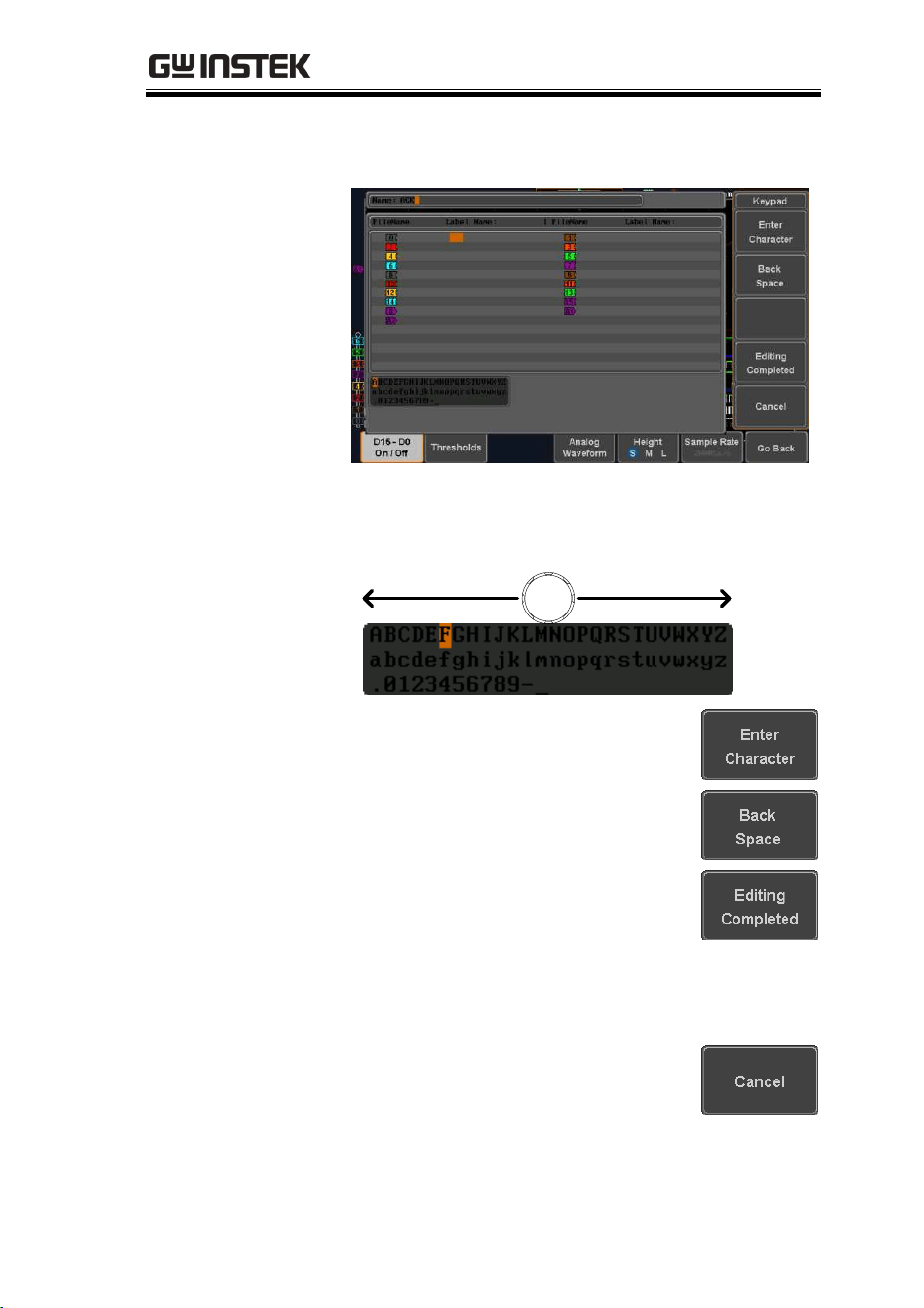
LOGIC ANALYZER
211
5. The Edit Label window appears.
6. Use the Variable knob to highlight
a character.
VARIABLE
Press Enter Character to select a
number or letter.
Press Back Space to delete a
character.
Press Editing Completed to create
the new label and return to the
previous menu.
Note: this key must be pressed to
create a label, even for a preset
label.
Press Cancel to cancel the editing
and return to the Edit Label menu.
7. The label will appear next to corresponding
channel indicator.

MDO-2000E series User Manual
212
Below, the label “LABEL_7” was created for
the D7 channel.
D7 is labeled as LABEL_7
Remove Label
Press Label Display to toggle the
selected label on or off.

ARBITRARY WAVE GENERATOR
213
ARBITRARY WAVE
GENERATOR
Arbitrary Wave Generator Operation .........................214
Overview ................................................................................................ 214
Rear Panel .............................................................................................. 214
AWG Display Overview ..................................................................... 215
Generator Connection ......................................................................... 215
Output Setup ......................................................................................... 216
Select the Active Channel ......................................................... 216
Turn the Output On for the Selected Channel ..................... 217
Setting the Load Impedance ..................................................... 217
Setting the Phase ......................................................................... 217
GEN1 and GEN2 Setup .................................................................... 218
Selecting a Waveform ................................................................ 218
Waveform Settings ..................................................................... 219
AM Modulation .................................................................................... 222
FM Modulation ..................................................................................... 224
FSK Modulation ................................................................................... 226
Sweep ...................................................................................................... 228
Manage Arbitrary Waveforms ............................................................ 230
Create New ARB Waveform .................................................... 230
Edit an Existing ARB Waveform ............................................ 231
Load ARB Waveform ................................................................ 239
Save ARB Waveform ................................................................. 240
Coupling and tracking waveforms settings ...................................... 243
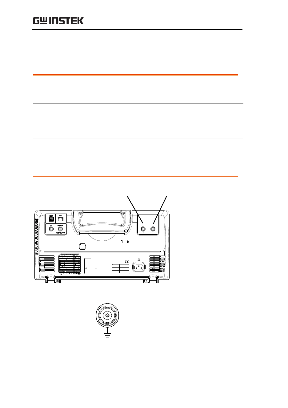
MDO-2000E series User Manual
214
Arbitrary Wave Generator Operation
Overview
Background
The AWG is a full-function dual channel arbitrary
waveform generator.
Waveforms
Arbitrary, Sine, Square, Pulse, Ramp, DC, Noise,
Sinc, Gaussian, Lorentz, Exp. Rise, Exp. Fall,
Haversine, Cardiac
Functions
AM, FM, FSK, Sweep
Rear Panel
GEN1 outputGEN2 output
GEN 2 GEN 1
LINE VOLTAGE
AC 100 240V
RANGE
FREQUENCY 50 60Hz
POWER MAX. 30 Watts
CAUTION
TO AVOID ELECTRIC SHOCK THE POWER CORD PROTECTIVE GROUNDING
DO NOT REMOVE COVERS. REFER SERVICING TO QUALIFIED PERSONNEL.
CONDUCTOR MUST BE CONNECTED TO GROUND.
Ser. No. Label
GEN1 and GEN2
Output
GEN 1
Outputs for the Generator 1 or
Generator 2 signals.
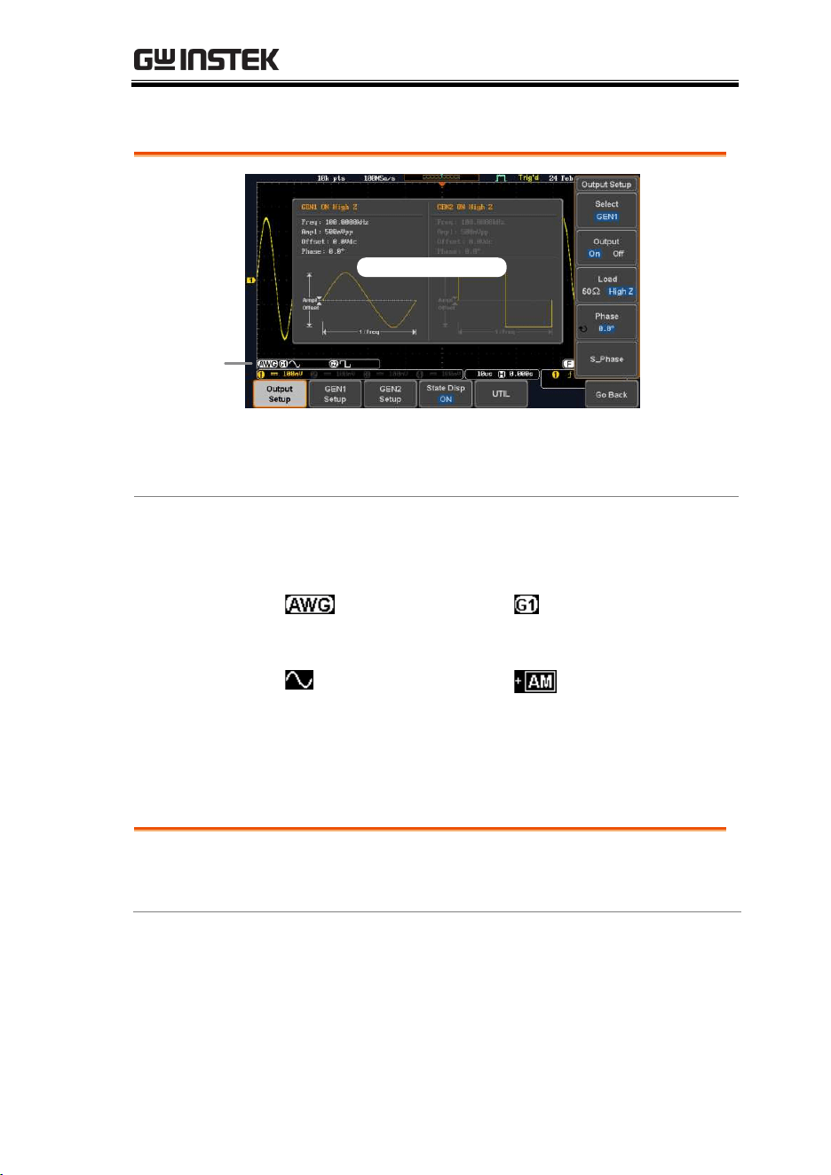
ARBITRARY WAVE GENERATOR
215
AWG Display Overview
AWG
generator
status
State Display
State Display
The state display is used to visually show the
major channel settings when you are in the AWG
menu.
AWG Generator
Status Indicators
The AWG channel status indicators show the
active channels, output waveforms and function.
AWG status
indicator
Channel status
indicator (G1, G2)
Waveform indicator
of the indicated channel
(Sine, arbitrary, pulse
etc...).
Function indicator
for the indicated channel
(AM, FM, FSK, SWP).
Generator Connection
Background
This section will explain how to connect a DUT to
the channel outputs.
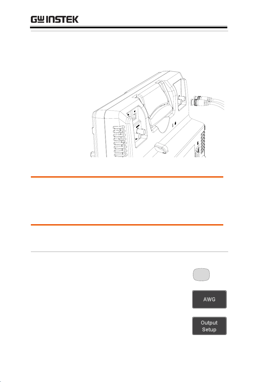
MDO-2000E series User Manual
216
Connection
1. Connect the BNC output (GEN1 or GEN2) to
the DUT using the GTL-101 BNC-Alligator clip
cables.
GEN1
GEN2
Output Setup
The Output Setup menu allows you to select a channel, to turn the
output on or off for the selected channel, configure the load
impedance and the phase of the output.
Select the Active Channel
Background
Before any operations can be performed on a
channel it must first be selected.
Panel Operation
1. Press the Option key.
Option
2. Press AWG from the bottom menu.
3. Press Output Setup.
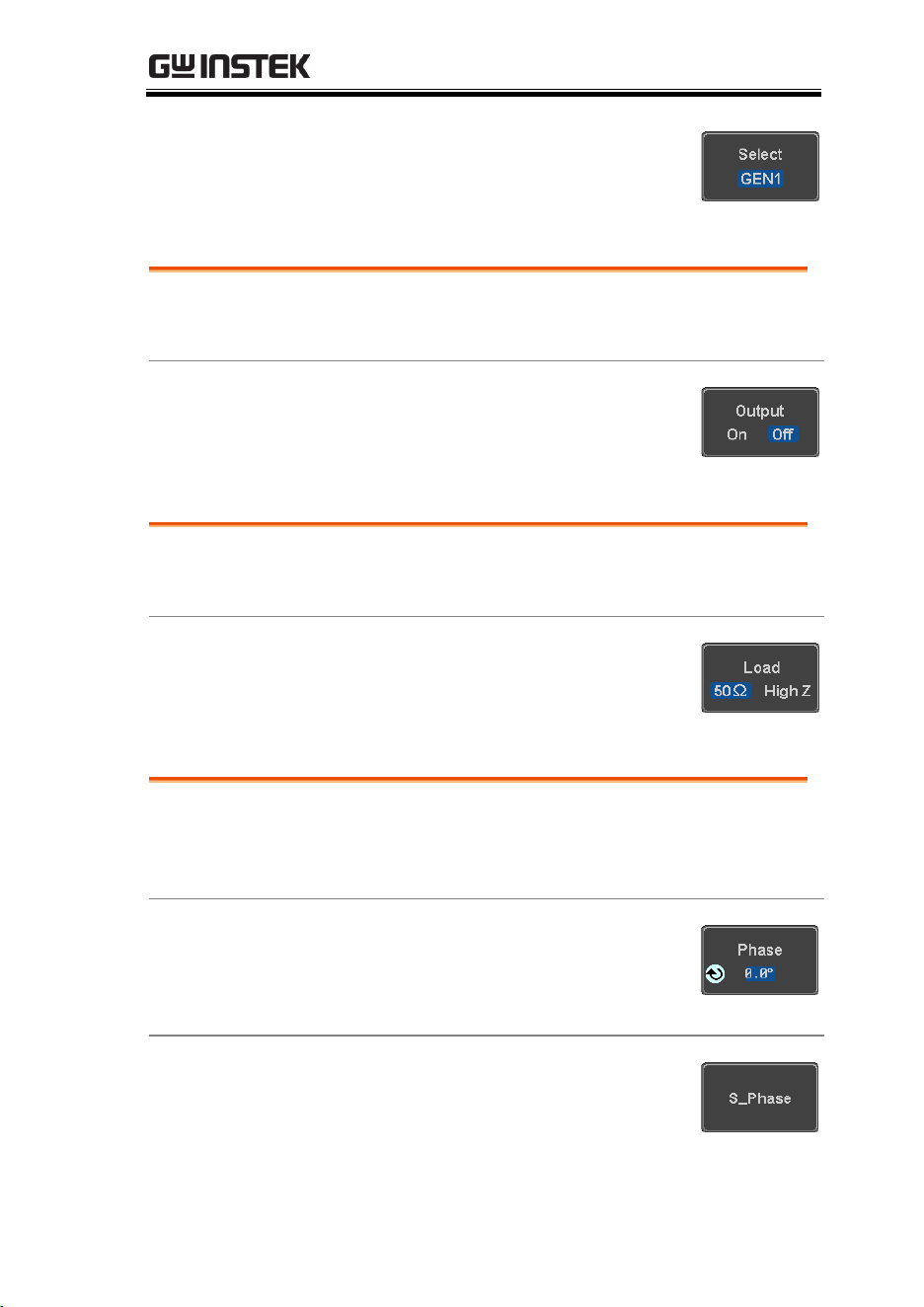
ARBITRARY WAVE GENERATOR
217
4. Press Select from the side menu
and choose GEN1 or GEN2.
Turn the Output On for the Selected Channel
Background
The output for each generator channel can be
turned on or off independently.
Panel Operation
1. Press Output to toggle the selected
channel on or off.
Setting the Load Impedance
Background
The load impedance can be independently set for
each generator channel.
Panel Operation
1. Press Load to toggle the impedance
between 50Ω and High Z.
Setting the Phase
Background
The output phase can only be set for the GEN1
output. GEN2 is always set to an output phase of
0°.
Panel Operation
1. Press Phase and use the variable
knob to set the phase.
Phase
-180° ~ 180°
Reset Phase
2. The phase can be reset by pressing
S_Phase.
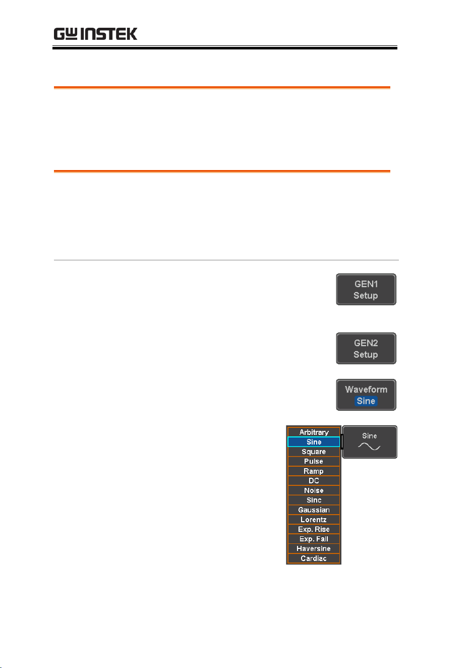
MDO-2000E series User Manual
218
GEN1 and GEN2 Setup
The GEN1 Setup and GEN2 Setup selects the output waveform,
waveform settings (amplitude, frequency, offset), modulation
mode or allows you to create arbitrary waveforms.
Selecting a Waveform
Background
The AWG option has 14 selectable waveforms,
including a user-created arbitrary waveform.
When using the modulation function, the
waveform selected here is also used as the carrier
wave.
Panel Operation
1. From the AWG menu press GEN1
Setup or GEN2 Setup to select the
waveform for generator 1 or
generator 2, respectively.
OR
2. Press Waveform from the bottom
menu.
3. From the side menu
press the waveform soft-
key and select a
waveform using the
variable knob.
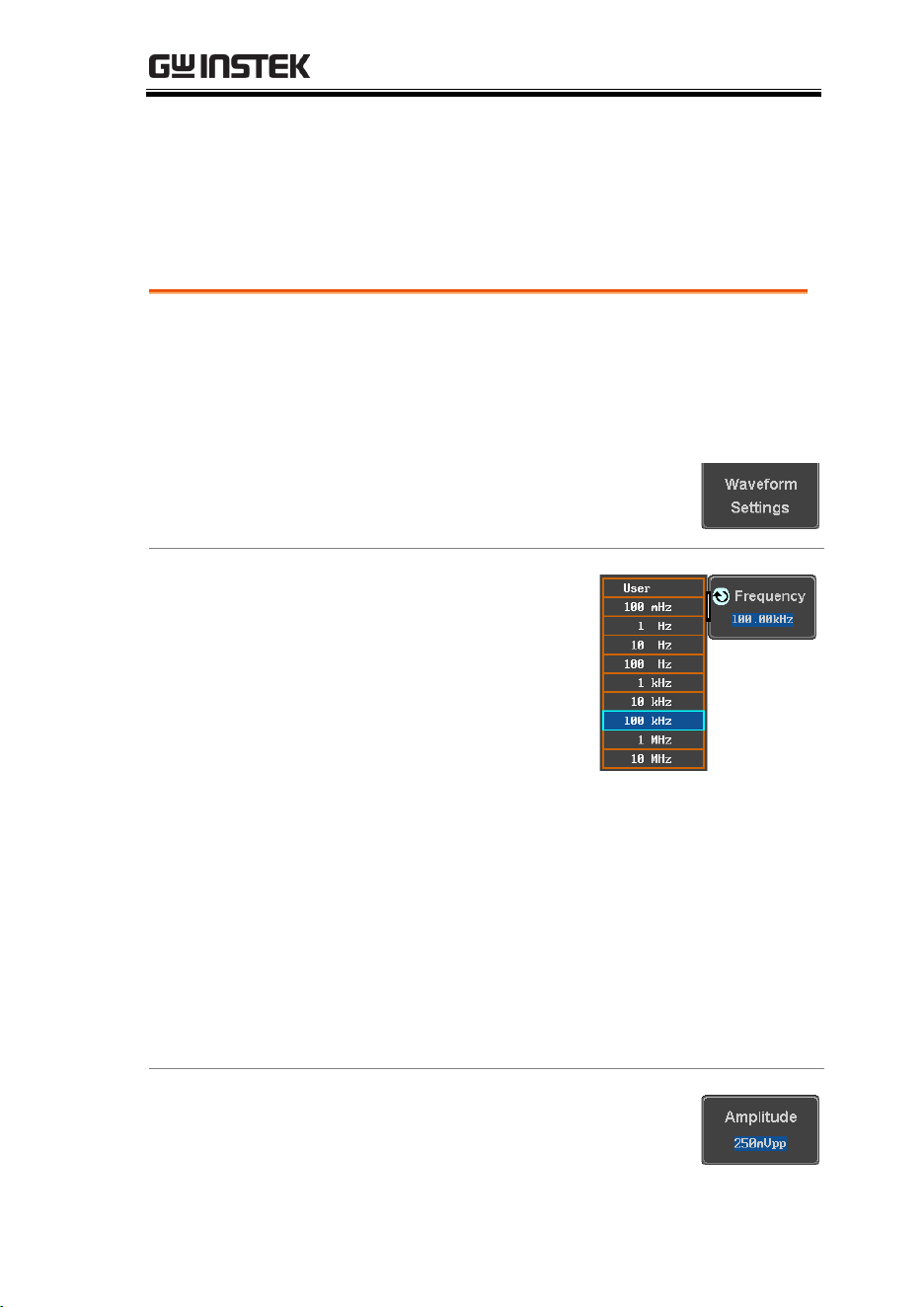
ARBITRARY WAVE GENERATOR
219
Selectable
waveforms
Arbitrary, sine, square, pulse,
ramp, DC, Noise, Sinc,
Gaussian, Lorentz, Exp. Rise,
Exp. Fall, Haversine, Cardiac.
Waveform Settings
Background
The Waveform Settings sub menu selects the
Frequency, amplitude and offset settings for
currently selected waveform in the GEN1 or GEN2
Setup menu.
1. From the Waveform menu, press
Waveform Settings from the side
menu.
Set the Frequency
2. Press Frequency to set the
frequency rate of the
waveform.
Note: When Frequency is
initially pressed the
variable knob can be
used to quick-select the
frequency step-
resolution. The variable
knob can then be used to
set the frequency in
increments of the step
resolution.
Range
Arbitrary, Sine: 100mHz ~ 25MHz
Square, Pulse: 100mHz ~ 15MHz
Others: 100mHz ~ 1MHz
Set the Amplitude
3. Press Amplitude to set the
amplitude of the waveform.
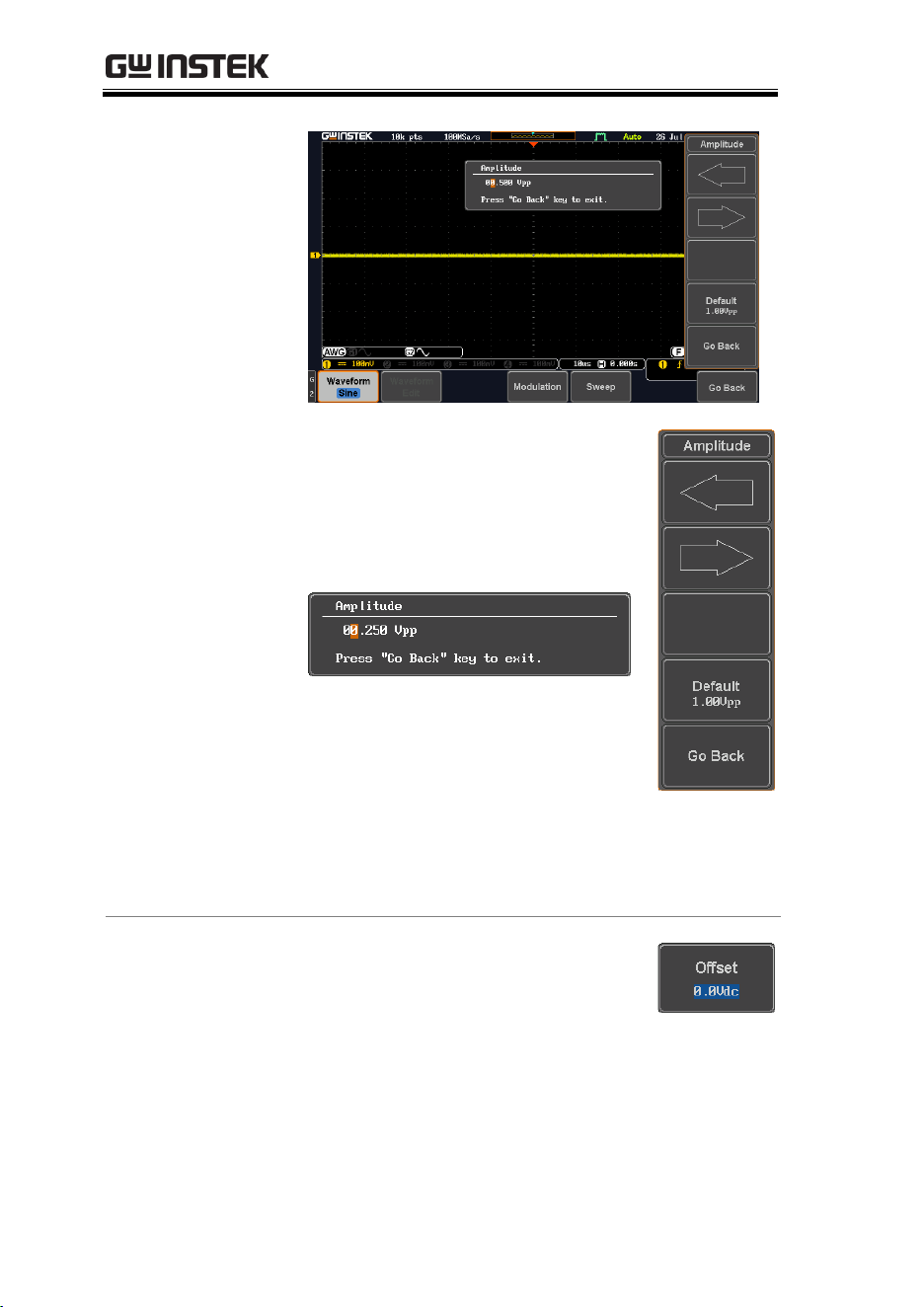
MDO-2000E series User Manual
220
4. Use the Left and Right arrow keys
to select a base unit and use the
variable knob to increase the
amplitude by that base unit, as
shown in the Amplitude window.
5. Default can be pressed to set the
amplitude to 1.00Vpp.
6. Press Go Back to leave the menu.
Range
10mVpp to 2.5Vpp (Load:50Ω)
20mVpp to 5Vpp (Load: High Z)
Default
1.00Vpp
Set the Offset
7. Press Offset to set the offset of the
waveform.
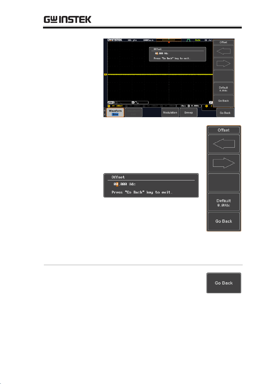
ARBITRARY WAVE GENERATOR
221
8. Use the Left and Right arrow keys
to select a base unit and use the
variable knob to increase the offset
by that base unit, as shown in the
Offset window.
9. Default can be pressed to set the
Offset to 0.00Vdc.
10. Press Go Back to leave the menu.
Range
Default
-1.245 ~ +1.245 (Load: 50Ω)
-2.49 ~ + 2.49 (Load: High Z)
0.00Vdc
Exit Waveform
Settings
11. Press Go Back to exit the waveform
settings.
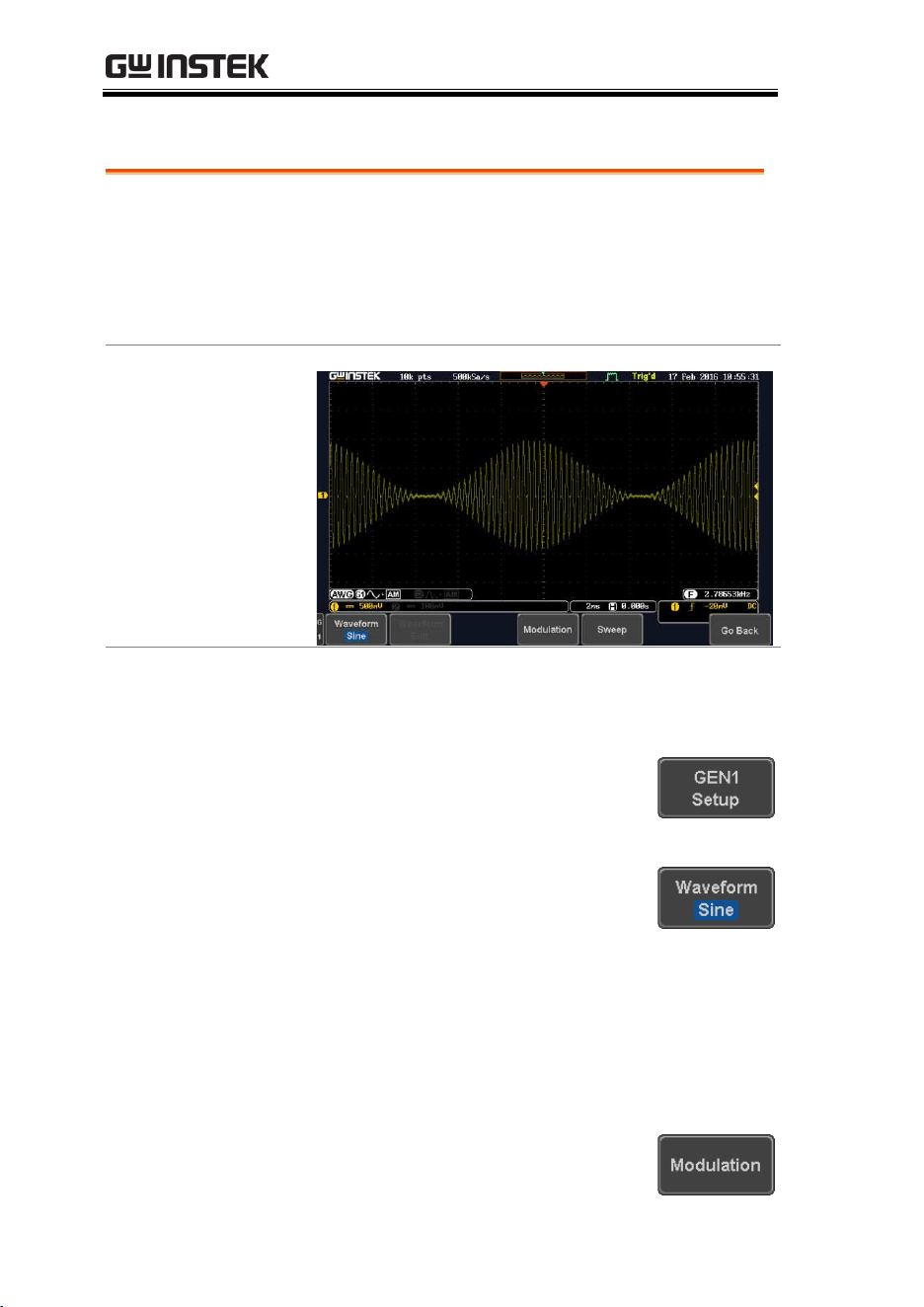
MDO-2000E series User Manual
222
AM Modulation
Background
Amplitude modulation can be used for either
channel. All waveforms except Noise and DC can
be used as the carrier wave. Sine, square, pulse,
ramp and noise can be selected as the modulating
waveform.
Example
Panel Operation
1. Select the carrier waveform from the GEN1
Setup/GEN2 Setup menu:
Press GEN1 Setup or GEN2 Setup
for generator 1 or generator 2,
respectively.
Press Waveform from the bottom
menu.
Select the waveform from the side menu. This
will be the carrier wave.
Carrier Waves
Sine, square, pulse, ramp, sinc,
gaussian, Lorentz, exp. rise,
exp. fall, haversine, cardiac.
2. Press the Modulation from the
bottom menu.
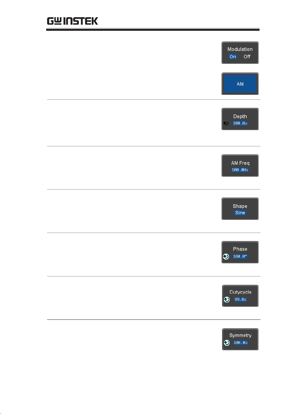
ARBITRARY WAVE GENERATOR
223
3. From the side menu, turn
Modulation on.
4. Press AM to select AM modulation
and to enter the AM modulation
setup menu.
Set the
Modulation
Depth
5. Press Depth to set the modulation
depth.
Depth
0.0% ~ 120.0%
Modulation
Frequency
6. Press AM Freq to set the
modulation frequency.
Frequency
200kHz ~ 1Hz
Shape
7. Press Shape to set the modulating
wave shape.
Shape
Sine, square, pulse, ramp, noise
Phase
(Sine wave only)
8. Press Phase to set the phase of the
modulated wave (sine wave).
Phase
-180.0° ~ 180.0°
Duty Cycle
(Pulse wave only)
9. Press Duty Cycle to set the duty
cycle (pulse wave).
Duty Cycle
2.0 ~ 98%
Symmetry
(Ramp wave only)
10. Press Symmetry to set the
symmetry (pulse wave).
Symmetry
0% ~ 100%
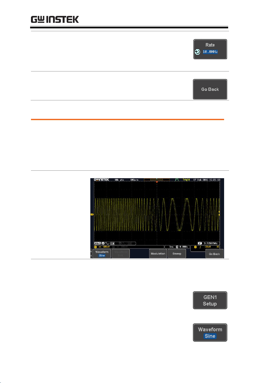
MDO-2000E series User Manual
224
Rate
(Noise wave only)
11. Press Rate to set the rate (noise
wave).
Noise
1kHz ~ 10MHz
Exit AM Settings
12. Press Go Back to exit the AM
settings.
FM Modulation
Background
Frequency modulation can be used for either
channel. The carrier wave can only be sine, square
and ramp waveforms. Sine, square, pulse, ramp
and noise can be selected as the modulating
waveform.
Example
Panel Operation
1. Select the carrier waveform from the GEN1
Setup/GEN2 Setup menu:
Press GEN1 Setup or GEN2 Setup
for generator 1 or generator 2,
respectively.
Press Waveform from the bottom
menu.
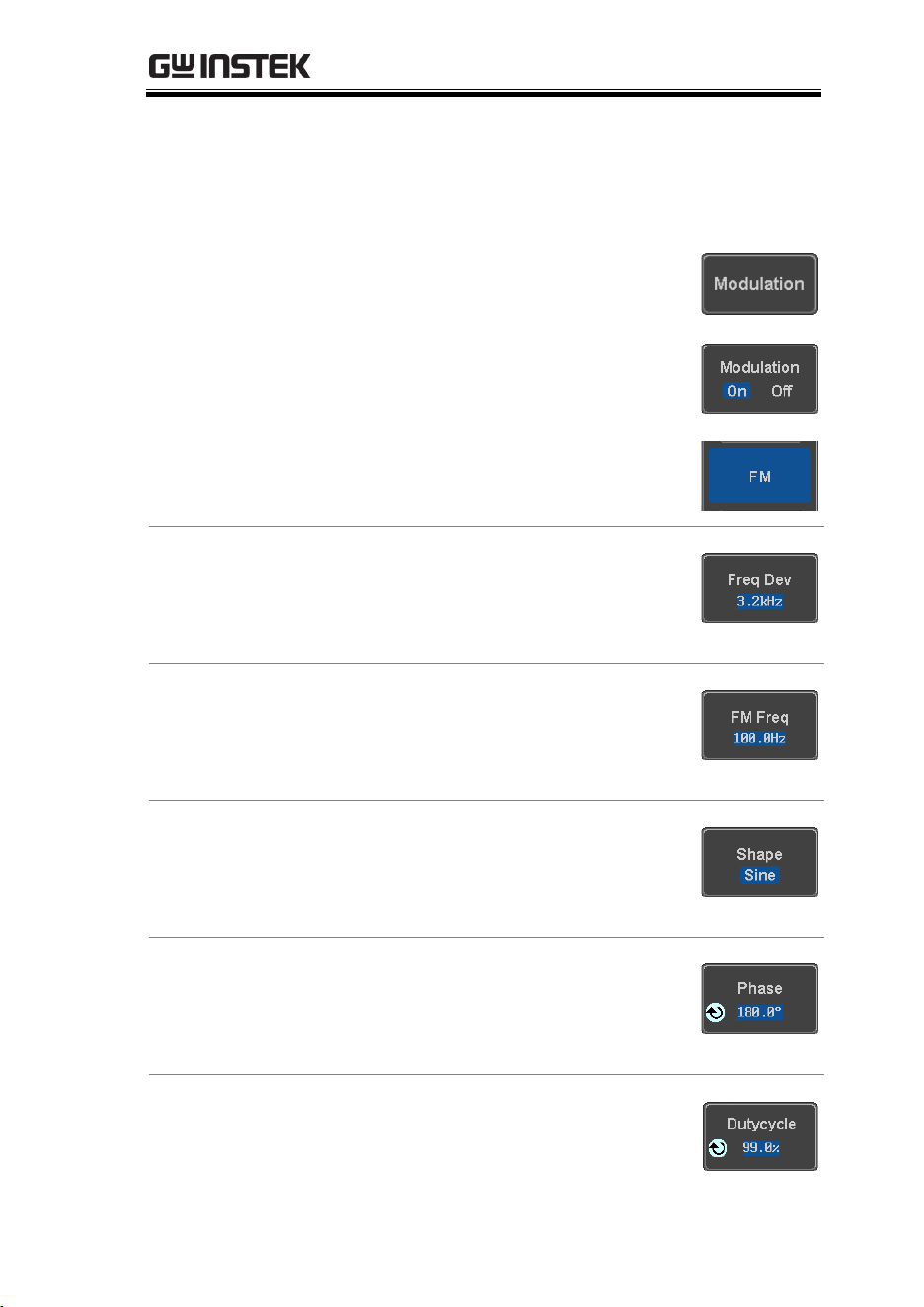
ARBITRARY WAVE GENERATOR
225
Select the waveform from the side menu. This
will be the carrier wave.
Carrier Waves
Sine, square, ramp
2. Press the Modulation from the
bottom menu.
3. From the side menu, turn
Modulation on.
4. Press FM to select FM modulation
and to enter the FM modulation
setup menu.
Set the Frequency
Deviation
5. Press Freq Dev to set the frequency
deviation.
Deviation
12.5MHz ~ 0.1Hz
Modulation
Frequency
6. Press FM Freq to set the
modulation frequency.
Frequency
200kHz ~ 1Hz
Shape
7. Press Shape to set the modulating
wave shape.
Shape
Sine, square, pulse, ramp, noise
Phase
(Sine wave only)
8. Press Phase to set the phase of the
modulated wave (sine wave).
Phase
-180.0° ~ 180.0°
Duty Cycle
(Pulse wave only)
9. Press Duty Cycle to set the duty
cycle (pulse wave).
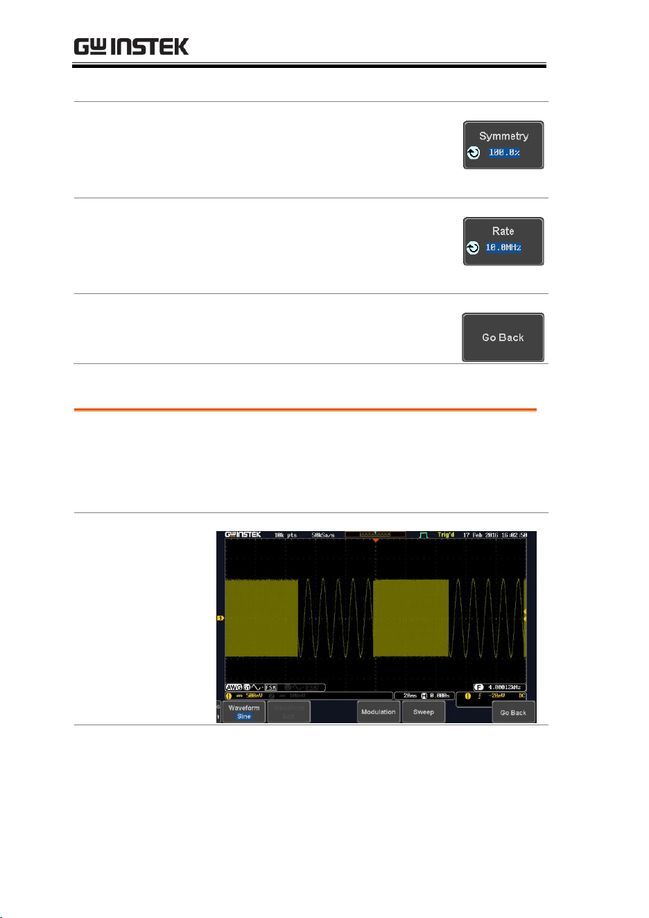
MDO-2000E series User Manual
226
Dutycycle
1% ~ 99%
Symmetry
(Ramp wave only)
10. Press Symmetry to set the
symmetry (ramp wave).
Symmetry
0% ~ 100%
Rate
(Noise wave only)
11. Press Rate to set the rate (noise
wave).
Rate
1kHz ~ 10MHz
Exit FM Settings
12. Press Go Back to exit the FM
settings.
FSK Modulation
Background
Frequency Shift Keying Modulation is used to shift
the frequency output of the function generator
between two preset frequencies (carrier frequency,
hop frequency).
Example
Panel Operation
1. Select the carrier waveform from the GEN1
Setup/GEN2 Setup menu:
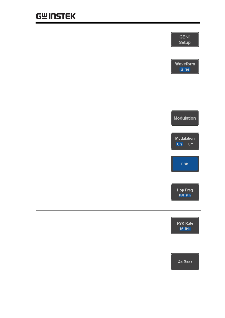
ARBITRARY WAVE GENERATOR
227
Press GEN1 Setup or GEN2 Setup
for generator 1 or generator 2,
respectively.
Press Waveform from the bottom
menu.
Select the waveform from the side menu. This
will be the carrier wave.
Carrier Waves
Sine, square, ramp
2. Press the Modulation from the
bottom menu.
3. From the side menu, turn
Modulation on.
4. Press FSK to select FSK
modulation and to enter the FSK
modulation setup menu.
Set the Hop Freq
5. Press Hop Freq to set the hop
frequency.
Hop Freq
25MHz ~ 0.1Hz
FSK Rate
6. Press FSK Rate to set the rate at
which the waveform switches from
the carrier and hop frequency.
FSK Rate
1Hz ~ 200kHz
Exit FSK Settings
7. Press Go Back to exit the FSK
settings.
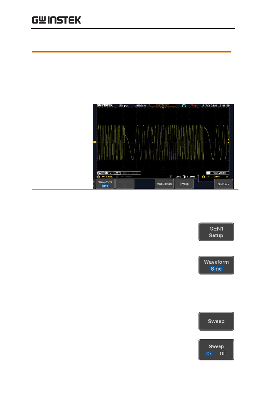
MDO-2000E series User Manual
228
Sweep
Background
The Sweep function can be used with sine, square
and ramp waveforms for either channel. The
function supports linear or logarithmic sweeping as
well as up or down sweeping.
Example
Panel Operation
1. Select the waveform from the GEN1
Setup/GEN2 Setup menu:
Press GEN1 Setup or GEN2 Setup
for generator 1 or generator 2,
respectively.
Press Waveform from the bottom
menu.
Select the waveform from the side menu.
Sweep Waves
Sine, square, ramp.
2. Press the Sweep from the bottom
menu.
3. From the side menu, turn Sweep
on.
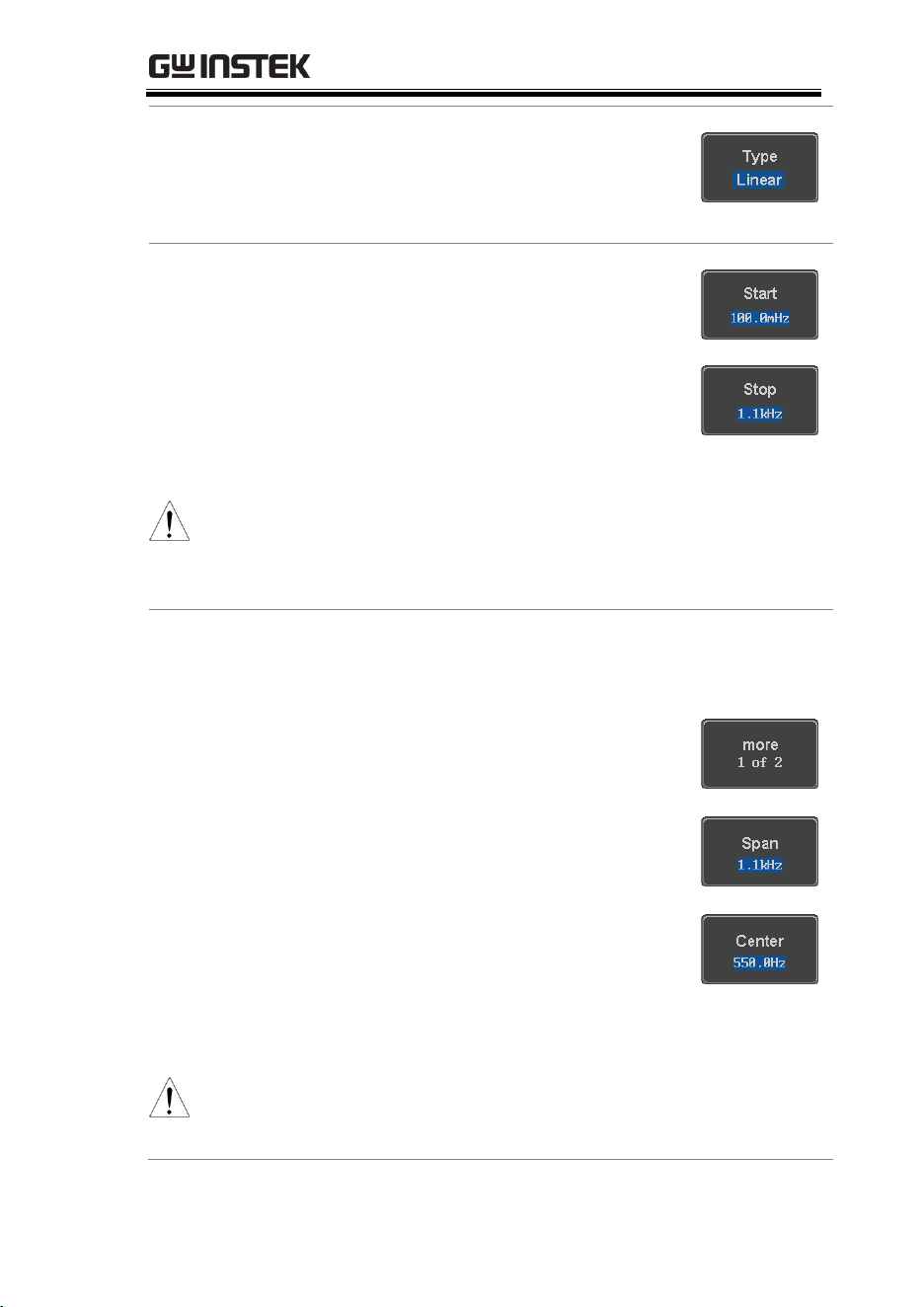
ARBITRARY WAVE GENERATOR
229
Type of Sweep
4. Press Type to set the sweep to
linear or logarithmic.
Type
Linear, Log
Start and Stop
Frequency
5. Press the Start or Stop soft-keys to
set the start and stop frequency,
respectively.
Start/Stop
25MHz ~ 0.1Hz
Note
To configure a up sweeping, set the start frequency at a
lower value than the stop frequency. To configure a
down sweeping, set the start frequency at a higher
value than the stop frequency.
Center Frequency
& Span
Alternatively the center frequency and span can be
set instead of the start and stop frequencies.
6. Press More 1 of 2.
7. Press Span to set the frequency
span of the sweep.
8. Press Center to set the center
frequency for the configured span.
Span
Center
25Mhz ~ -25MHz
25MHz ~ 0.1Hz
Note
To configure a up sweeping, set the span with a
positive frequency. To configure a down sweeping, set
the span with a negative frequency.
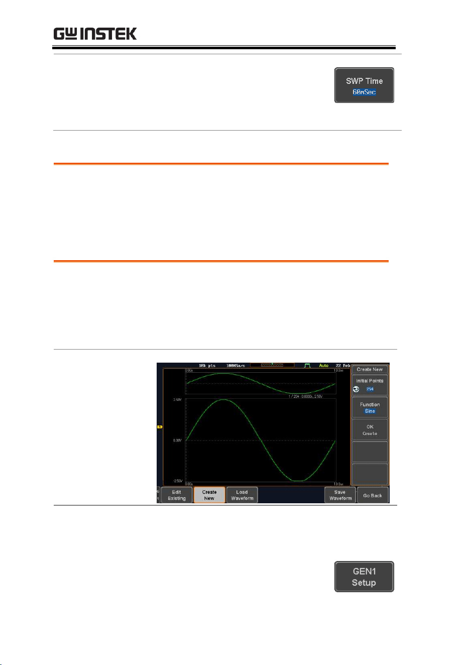
MDO-2000E series User Manual
230
Sweep Time
9. Press SWP Time to set how long
the sweep takes to go from the
start to the stop frequency.
Sweep time
5.0us ~ 10s
Manage Arbitrary Waveforms
The Arbitrary Waveform menus allow you to create, edit, recall and
save arbitrary waveforms. The menus are accessible via the
Waveform Edit button on the bottom menu once GEN1 or GEN2 has
been setup with an arbitrary waveform.
Create New ARB Waveform
Background
The Create New menu is used to load an inbuilt
waveform with a defined length in order to build
the shape of the arbitrary waveform. Supported
waveforms include: Sine, Square, Pulse, Ramp and
Noise.
Example
Panel Operation
1. Select an arbitrary waveform from the GEN1
Setup/GEN2 Setup menu:
Press GEN1 Setup or GEN2 Setup
for generator 1 or generator 2,
respectively.
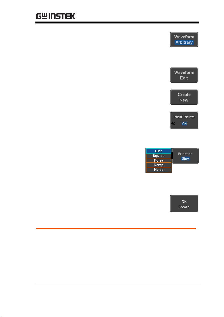
ARBITRARY WAVE GENERATOR
231
Press Waveform from the bottom
menu.
Select Arbitrary from the side menu.
2. Press the Waveform Edit from the
bottom menu.
3. From the bottom menu select
Create New.
4. Press Initial Points to set the
number of points for the waveform
length.
Initial Points
2 ~ 16384
5. Press Function to choose
an inbuilt waveform :
Function:
Sine, Square, Pulse, Ramp,
Noise
6. Press OK Create to create the
arbitrary waveform shape.
Edit an Existing ARB Waveform
Background
Use the Edit Existing menu to edit a newly created
waveform and further shape it according to your
requirements. You can also use the Edit Existing
menu for arbitrary waveforms that have been
recalled (see Load Waveform page 239). There are
two main options that can be used to edit
waveforms: Normal Edit and Function Edit.
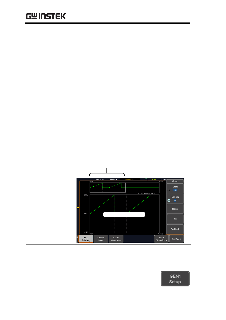
MDO-2000E series User Manual
232
Editing Methods
Normal Edit:
The Normal Edit function allows you to insert
or delete points at any position on a waveform.
Function Edit:
The Function Edit function allows you to edit
the waveforms in a number of different ways:
Point/Line: Insert a point or horizontal line
into the ARB waveform.
Diagonal: Insert a diagonal line
Scale: Scales the ARB waveform vertically.
Copy/Paste: Copy or paste a section of the
ARB waveform.
Clear: Clears a section of the ARB waveform
and replaces it with a 0V DC waveform.
Example
This box shows the editing
window in relation to the full
ARB waveform
Editing window
Panel Operation
1. Select a waveform from the GEN1 Setup/GEN2
Setup menu:
Press GEN1 Setup or GEN2 Setup
for generator 1 or generator 2,
respectively.
ARBITRARY WAVE GENERATOR
233
Press Waveform from the bottom
menu.
Select Arbitrary from the side menu.
2. Press the Waveform Edit from the
bottom menu.
Edit Existing
3. From the bottom menu select Edit
Existing.
This will allow you to edit the ARB
waveform that is currently loaded
in memory. If no waveform has
been loaded, a DC waveform is
shown.
Normal Edit
4. Press Normal Edit to insert a point
or delete a point from the
waveform:
Insert Point:
To insert a point, you must first set the position
of the point to be inserted.
a. Press Point to set the x-axis
position of the point.
Point
1 ~ user-defined point position
b. Press Level to set the
amplitude of the point. The
max/min amplitude depends
on the waveform amplitude
settings, see page 219.
Level
±1.25Vdc (Load: 50Ω)
±2.5Vdc (Load: High Z)
MDO-2000E series User Manual
234
c. Press Insert Point. The inserted
point will increase the length
of the waveform by one point.
Delete Point:
d. Press Delete Point to delete the
point set with the “Point”
soft-key.
The overall length of the
waveform will be shortened
by one point.
Exit Normal Edit
5. Press Go Back to exit the Normal
Edit.
Function Edit
6. Press Function Edit to perform
more advanced editing functions.
7. Press Edit Method to
choose the editing
method:
Edit Method:
Point/Line
Diagonal
Scale
Copy/Paste
Clear
8. Press Action to begin using the
selected editing method:
Point/Line:
a. Press Point/Level once to select
the point’s X-axis start point.
ARBITRARY WAVE GENERATOR
235
Press Point/Level again to
select the amplitude (Level)
Point
1 ~ user-defined point position
Level
±1.25Vdc (Load: 50Ω)
±2.5Vdc (Load: High Z)
b. Press Length to set the length
of the line.
Length
0 ~ user-defined point length
c. The Adjustment soft-key can
be used to toggle the step
resolution of the variable
knob when editing values in
this menu.
Adjustment
Fine, Coarse
d. Press Preview. The desired edit
will then be previewed on the
screen.
e. Press Done to confirm the edit,
or press Undo to cancel.
f. Press Go Back to go back to the
previous menu.
Diagonal:
a. Press Point1/Level1 once to
select the point’s X axis start
point.
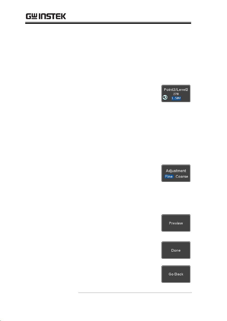
MDO-2000E series User Manual
236
Press Point1/Level1 again to
select the amplitude (Level) of
the start point.
Point1
1 ~ user-defined point position
Level1
±1.25Vdc (Load: 50Ω)
±2.5Vdc (Load: High Z)
b. Press Point2/Level2 once to
select the point’s X axis end
point.
Press Point2/Level2 again to
select the amplitude (Level) of
the end point.
Point2
1 ~ user-defined point position
Level2
±1.25Vdc (Load: 50Ω)
±2.5Vdc (Load: High Z)
c. The Adjustment soft-key can
be used to toggle the step
resolution of the variable
knob when editing values in
this menu.
Adjustment
Fine, Coarse
d. Press Preview. The desired
edit will then be previewed on
the screen.
e. Press Done to confirm the edit,
or press Undo to cancel.
f. Press Go Back to go back to the
previous menu.
Scale:
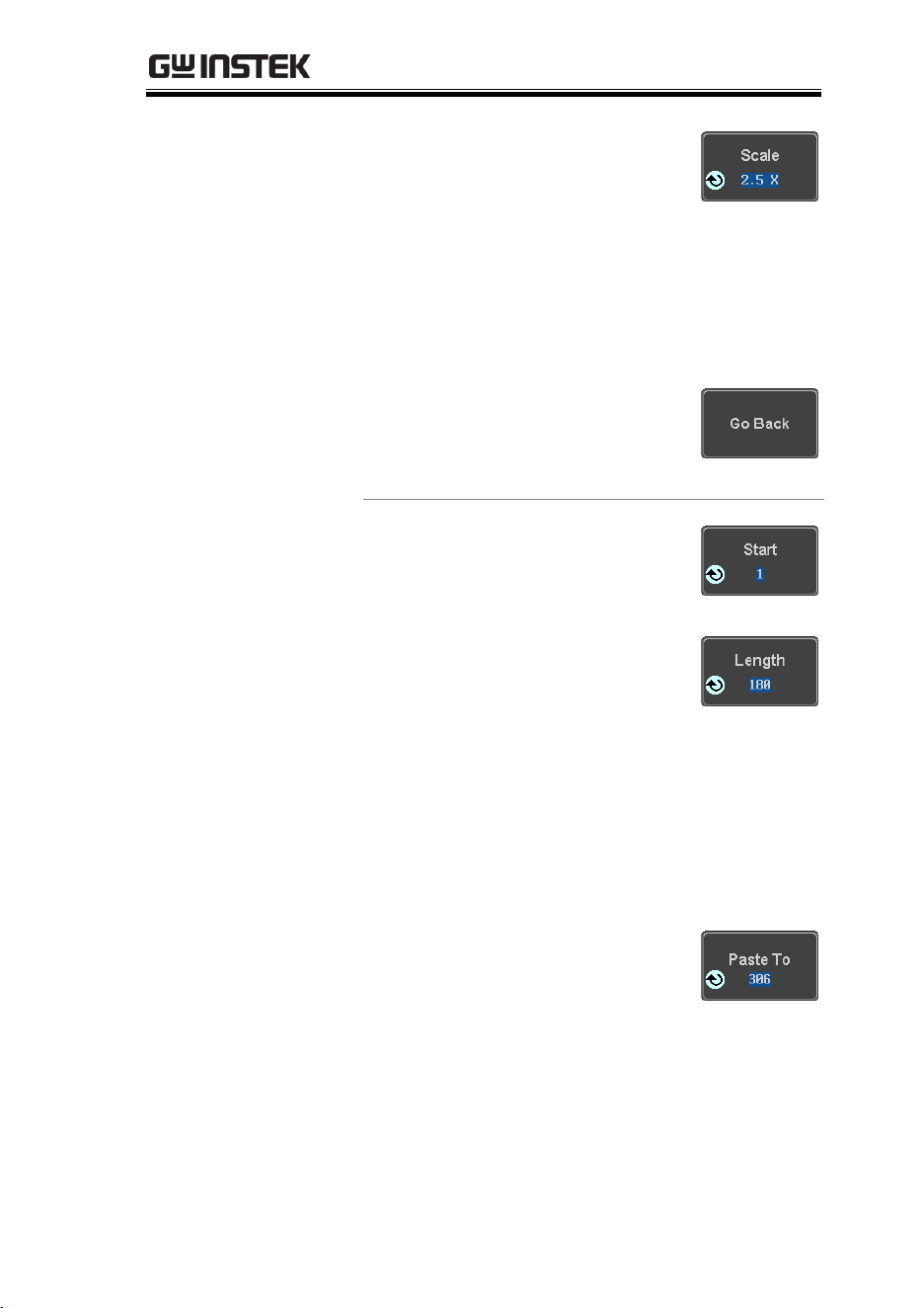
ARBITRARY WAVE GENERATOR
237
a. Press Scale and use the
variable knob to set the scale
of the waveform vertically.
Note: If the waveform exceeds
the maximum amplitude it
will be clipped.
Scale
0.1x ~ 10X
b. Press Go Back to go back to the
previous menu.
Copy/Paste:
a. Press Start to set the start
point of the section you want
to copy.
b. Press Length to set the size of
the section you want to copy
from the start point.
The copied section will be
shown as a grey box on the
display
Start
1 ~ user-defined point position
Length
1 ~ user defined point length
c. Press Paste To to choose where
the selected section is copied
to.
Paste To
1 ~ user defined point position
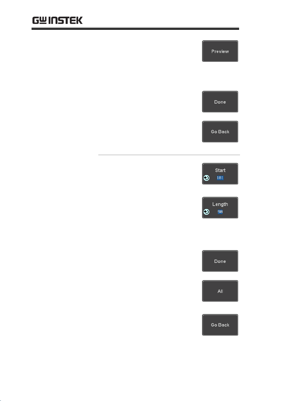
MDO-2000E series User Manual
238
d. Press Preview. The desired edit
will then be previewed on the
screen. The pasted section will
be shown as a yellow box on
the screen.
e. Press Done to confirm the edit,
or press Undo to cancel.
f. Press Go Back to go back to the
previous menu.
Clear Section:
a. Press Start to set the start
point of the section you want
to clear.
Press Length to set the size of
the section you want to clear.
Start
1 ~ user-defined point position
Length
1 ~ user-defined point length
b. Press Done to clear the
selected section.
c. Alternatively, press All to
clear the entire waveform
from the screen.
d. Press Go Back to go back to the
previous menu.
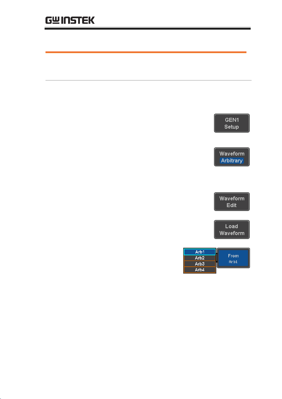
ARBITRARY WAVE GENERATOR
239
Load ARB Waveform
Background
ARB waveforms can be loaded from internal
memory or from an external USB storage.
Panel Operation
1. Select a waveform from the GEN1 Setup/GEN2
Setup menu:
Press GEN1 Setup or GEN2 Setup
for generator 1 or generator 2,
respectively.
Press Waveform from the bottom
menu.
Select Arbitrary from the side menu.
2. Press Waveform Edit from the
bottom menu.
3. From the bottom menu select Load
Waveform.
4. To load a file from one
of the internal memory
slots, press From to
choose the ARB
waveform to load:
ARB:
Arb1, Arb2, Arb3, Arb4
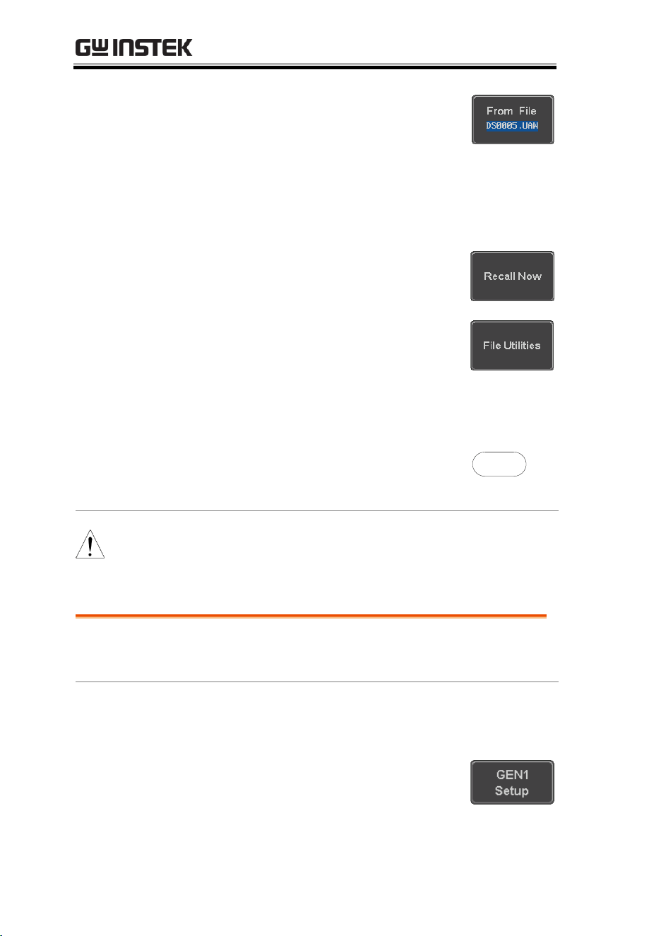
MDO-2000E series User Manual
240
5. To load a file from an external USB
or from the internal flash memory,
press From File.
The last file that was saved to USB
or the internal flash memory will
be displayed in the icon.
6. To recall the displayed file, press
Recall Now.
7. Alternatively, press File Utilities.
Use the Variable knob to select the
desired ARB waveform.
Press the Select key to load the
selected ARB waveform in the file
utilities screen.
Select
Note
Press
File Utilities
to manage the files on the internal
disk or an inserted USB disk. See page 329 for details.
Save ARB Waveform
Background
ARB waveforms can be saved to internal memory
or to an external USB storage.
Panel Operation
1. Select a waveform from the GEN1 Setup/GEN2
Setup menu:
Press GEN1 Setup or GEN2 Setup
for generator 1 or generator 2,
respectively.
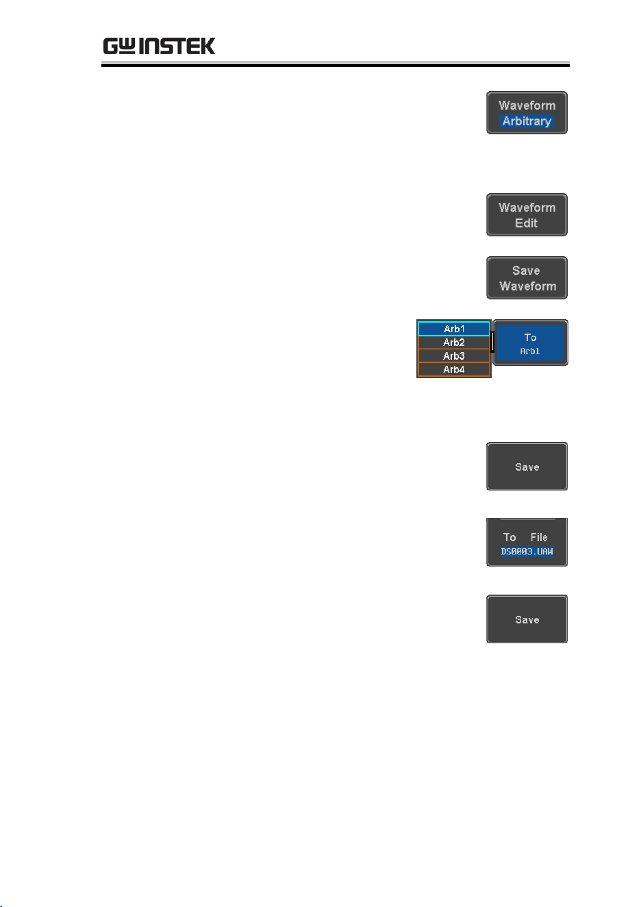
ARBITRARY WAVE GENERATOR
241
Press Waveform from the bottom
menu.
Select Arbitrary from the side menu.
2. Press Waveform Edit from the
bottom menu.
3. From the bottom menu select Save
Waveform.
4. To save to one of the
internal memory slots,
press To to choose the
ARB waveform to save:
ARB:
Arb1, Arb2, Arb3, Arb4
Press Save to save the waveform to
the selected memory slot, Arb1,
Abr2, Arb3 or Arb4.
5. Alternatively, to save to a USB
drive or to the internal flash
memory, press To File.
6. To save the selected file, press Save
waveform.
7. You will automatically be taken to a file utility
where you will be able to edit the name of the
file.
8. To edit the file name, use the Variable knob to
highlight a character.
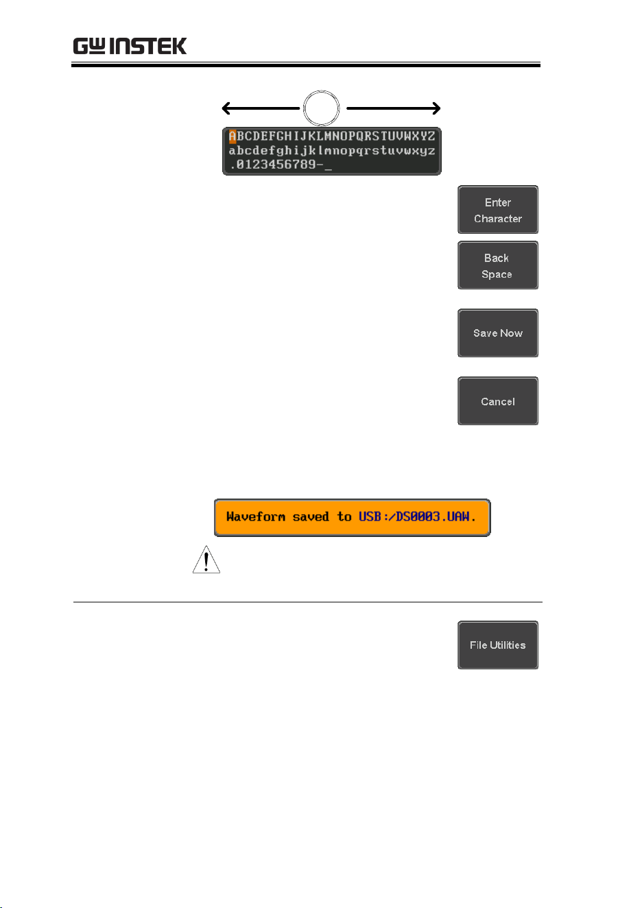
MDO-2000E series User Manual
242
VARIABLE
Press Enter Character or the Select
key to select a number or letter.
Press Back Space to delete a
character.
9. Press Save Now to save the file.
Note: Pressing Cancel will cancel
the save operation and return you
to the Save Waveform menu.
After Save Now has been pressed the file will be
saved.
Note
The file will not be saved if the power
is turned off or the USB drive is taken
out before the message ends.
File Utility
Alternatively, to edit the internal
memory or the USB flash drive
contents (create/ delete/rename files
and folders) or to edit the default file
path, press File Utilities from the side
menu. See the user manual for details
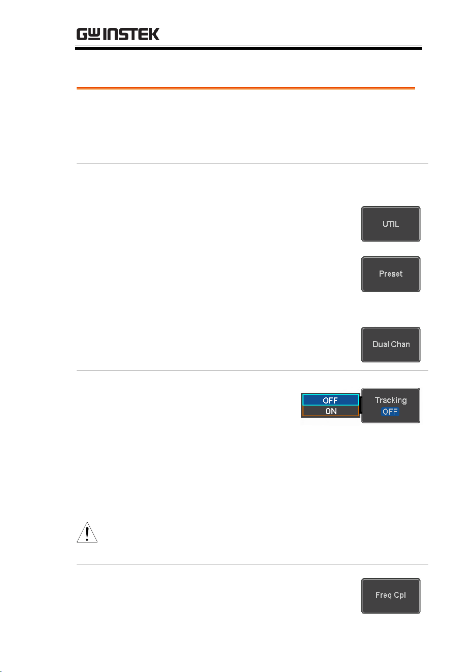
ARBITRARY WAVE GENERATOR
243
Coupling and tracking waveforms settings
Background
GEN1 and GEN2 waveforms can be coupled in
terms of frequency and/or amplitude. Similarly,
waveform settings can also be tracked and be
duplicated from one waveform to the other.
Panel Operation
1. From the bottom menu of the AWG menu:
Press UTIL to enter the Utility
menu.
You can press on the Preset button
from the side menu to reset both
wave generators to a 0V DC
waveform.
2. Press Dual Chan from the side
menu to enter the coupling and
tracking menus.
Tracking settings
3. From the side menu
press Tracking to set
the tracking mode to
ON or OFF.
Tracking:
ON, OFF
When Tracking is ON, all parameters set to one
waveform will be copied to the other one and
vice-versa.
Note
Tracking mode cannot be used together with the
Frequency or Amplitude Coupling. Setting the Tracking
mode to ON will disable any Coupling settings.
Frequency
coupling
4. From the side menu press Freq Cpl
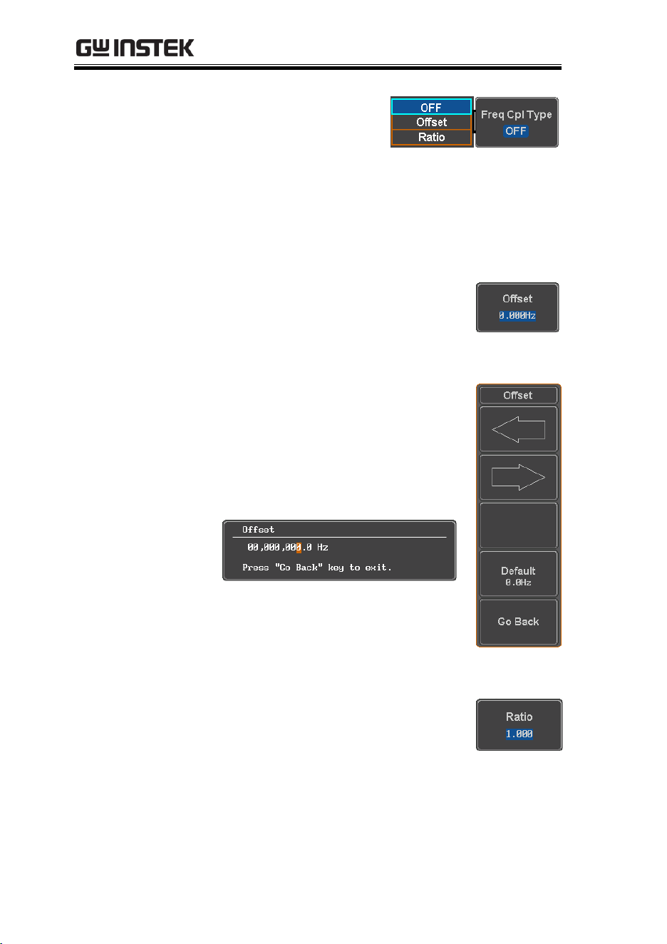
MDO-2000E series User Manual
244
5. Press Freq Cpl Type to
set the type of
frequency coupling.
Freq Cpl Type:
OFF, Offset, Ratio
Frequency from both generated waveforms can
be coupled with a fixed offset or with a constant
ratio.
6. Select Offset from the Freq Cpl Type
menu and press Offset on the side
menu to configure the offset of the
frequency coupling.
7. Use the Left and Right arrow keys
to select a base unit and use the
variable knob to increase or
decrease the offset by that base
unit, as shown in the Offset
window.
8. Default can be pressed to set the
Offset to 0.0Hz.
9. Press Go Back to leave the menu.
10. Select Ratio from the Freq Cpl Type
menu and press Ratio on the side
menu to configure the ratio of the
frequency coupling.
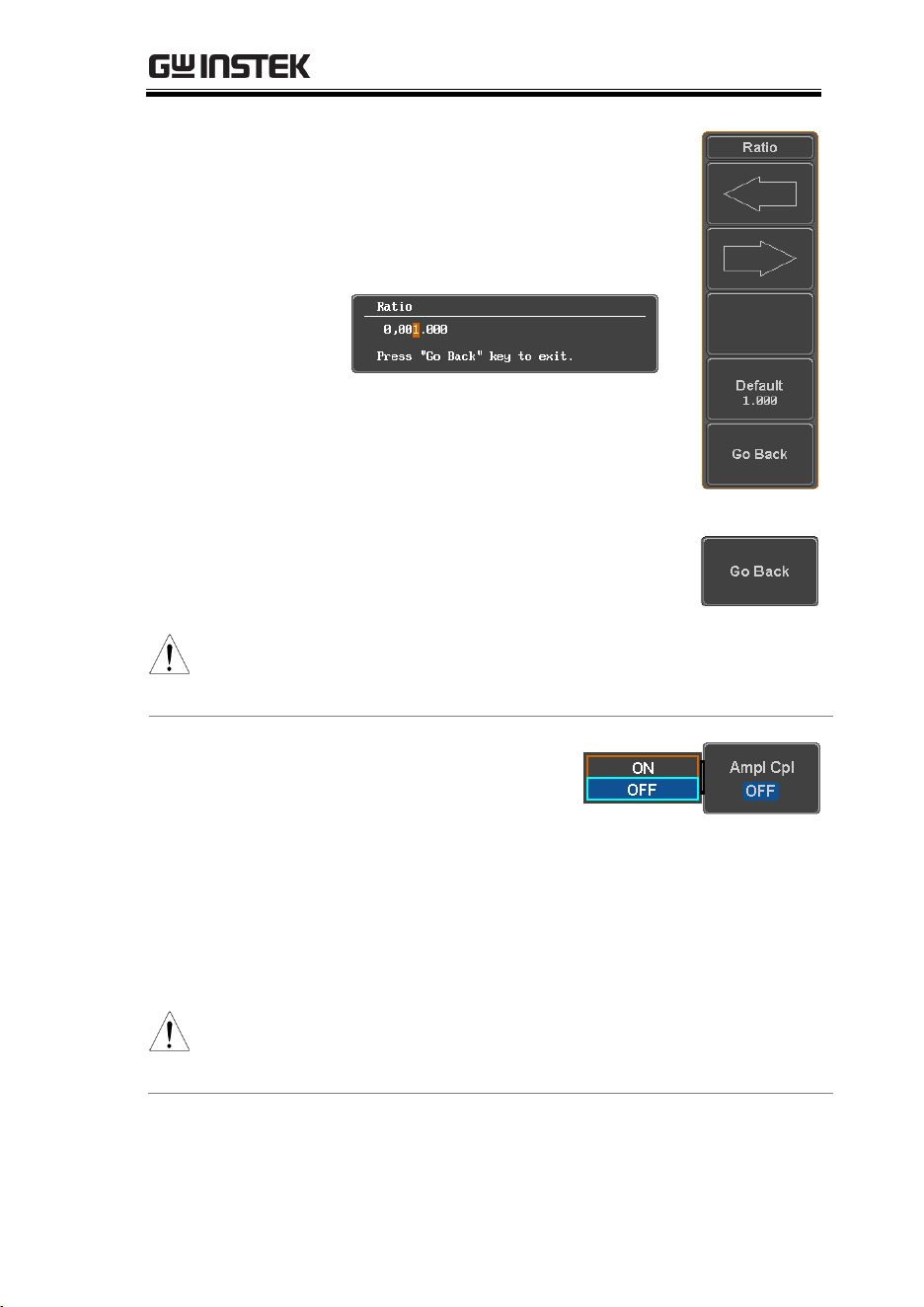
ARBITRARY WAVE GENERATOR
245
11. Use the Left and Right arrow keys
to select a base unit and use the
variable knob to increase or
decrease the ratio by that base unit,
as shown in the Ratio window.
12. Default can be pressed to set the
Ratio to 1.000.
13. Press Go Back to leave the menu.
14. Press again Go Back to leave the
menu Frequency Coupling menu.
Note
Frequency Coupling cannot be set if Tracking is ON.
Configuring Frequency Coupling parameters will
disable the Tracking mode.
Amplitude
coupling
15. Press Ampl Cpl to set
the amplitude
coupling to ON or
OFF.
Ampl Cpl:
OFF, ON
When set to ON, amplitude from both generated
waveforms will be duplicated from one to the
other one.
Note
Amplitude Coupling cannot be set if Tracking is ON.
Configuring Amplitude Coupling will disable the
Tracking mode.

MDO-2000E series User Manual
246
Reset the phase
16. You can also reset the phase to 0°
between the two waveforms by
pressing S_Phase.

SPECTRUM ANALYZER
247
SPECTRUM ANALYZER
Spectrum Analyzer operation ....................................248
Overview ................................................................................................ 248
Display Overview ................................................................................. 249
Connections ........................................................................................... 250
Configuration ........................................................................................ 251
Selecting the source .................................................................... 251
Setting the trace mode options (Trace type) .......................... 252
Setting the Detection Method .................................................. 254
Configuring the Frequencies and Span ................................... 255
Configuring the Bandwidth ...................................................... 259
Configuring the Amplitude ....................................................... 260
Measurement ......................................................................................... 262
Using the Search function ......................................................... 262
Using the Cursors ....................................................................... 263

MDO-2000E series User Manual
248
Spectrum Analyzer operation
Overview
Background
The Spectrum Analyzer is a real-time spectrum
analyzer specially designed for the MDO-2000E
SERIES. It conveniently allows users to analyze
the signal in the frequency domain.
Windows
Hanning, Rectangular, Hamming, Blackman
Frequency range
DC to 500MHz Max (Maximum frequency to
500MHz uncalibrated)
Spin
1kHz to 500MHz Max.
Resolution
bandwidth
1Hz to 500kHz Max.
Functions
Compatible with the search and cursor functions
for accurate measurement in the frequency
domain.
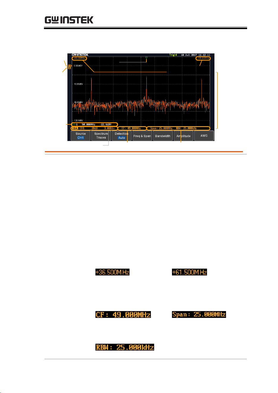
SPECTRUM ANALYZER
249
Display Overview
Waveform in
frequency
domain
Zero
level
Peaks
Events
State
View
Start and stop
span frequencies
Source and V scale
Center frequency
Span and resolution
Trace
type
Main
display
Main display
The Spectrum Analyzer main display can show
various spectrum traces of the selected analog
source channel, such as the normal, max-hold,
min-hold and averaged trace. The start and stop
frequency of the span are displayed at both top
sides. The remaining frequency span information
is displayed at the bottom as well as the vertical
scale. The zero level is shown for reference on the
Y axis on the left. When the search function is
enabled, frequency peaks will be detected and
summarized in the Events State View window at
the bottom left of the display.
Frequency
domain
information
Start
frequency (shown on the
upper left corner of the
main spectrum display)
Stop
frequency (shown on the
upper right corner of the
main spectrum display)
Center frequency of the
span
Width of the span
Resolution bandwidth
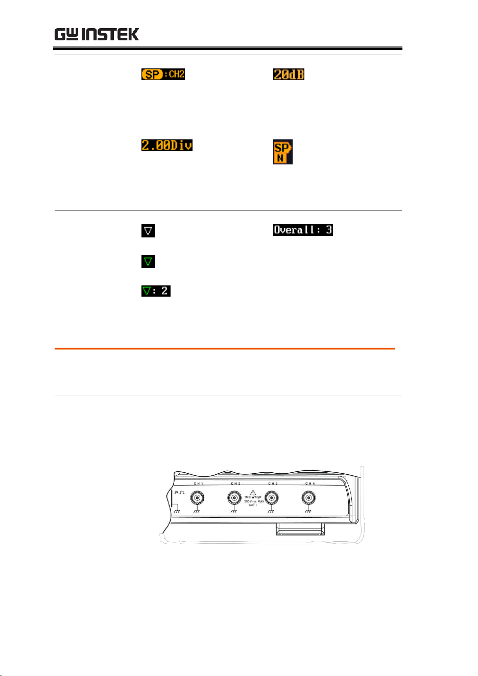
MDO-2000E series User Manual
250
Vertical scale
information
Active source
channel for the spectrum
analyzer
Vertical scale per
one division
Zero level
position
Shows the zero
position along the Y-axis
(SP) and the type of
trace (N = Normal)
Peaks
Peak mark
Current active peak
Active peak
marker
Total
number of peaks
detected (according to
the search function
parameters).
Connections
Background
The Spectrum Analyzer uses the analog channel
inputs of the MDO-2000E SERIES.
Connection
1. Connect the desired signal source to one of the
analog channel input of the DSO using BNC
connectors (illustration below with a 4-channel
MDO-2000EG/2000EX series model).
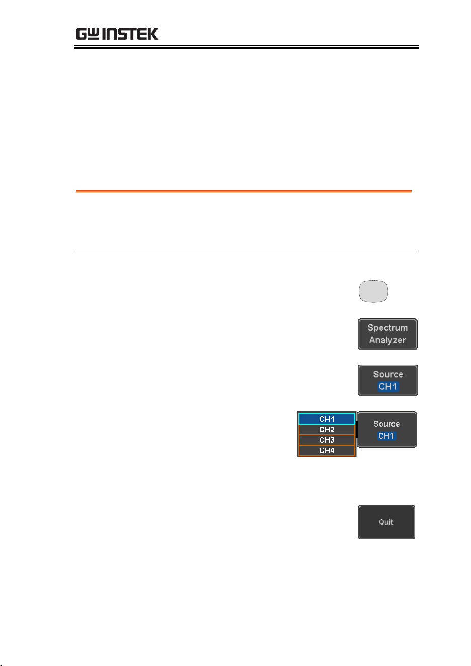
SPECTRUM ANALYZER
251
Configuration
Setting up a spectrum trace can be done by following the
subsequent steps: selecting the source, tuning the trace with its
associated detection options, configuring the frequencies and span,
configuring the window type and the frequency resolution and
lastly configuring the vertical scale.
Selecting the source
Background
Before any visualization or measurement can be
performed on the spectrum analyzer, it must first
be associated with a source.
Panel Operation
1. Press the Option key.
Option
2. Press Spectrum Analyzer from the
bottom menu.
3. Press Source from the bottom
menu.
4. Press Source from the
side menu and choose
a source.
Range
CH1 ~ CH4 for 4-channel models
CH1 ~ CH2 for 2-channel models
5. Press Quit from the side menu to
exit the spectrum analyzer
function.
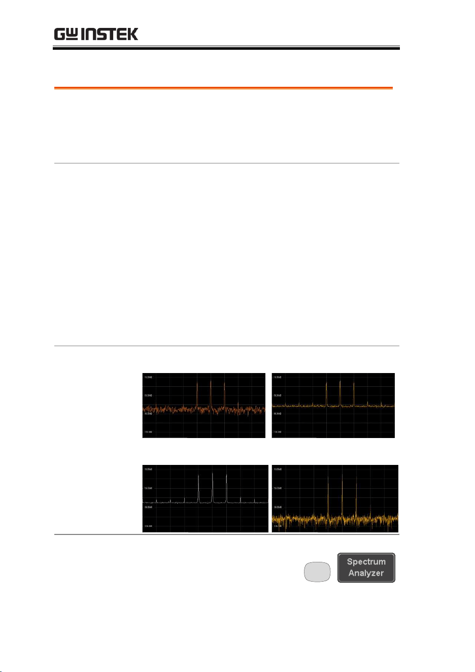
MDO-2000E series User Manual
252
Setting the trace mode options (Trace type)
Background
Trace options determine how the trace data is
stored or manipulated before being displayed. The
Spectrum Analyzer updates the trace according to
the type of trace.
Definitions
Normal: the Spectrum Analyzer continuously
updates the display with each sweep.
Max/Min Hold: the maximum/minimum points
are maintained for the selected trace. The trace
points are updated each sweep if a new
maximum/minimum point is found.
Average: this mode averages the trace for a user-
defined number of times before it is displayed.
This type of trace smoothes the noise level, but it is
slower to update.
Example
Normal trace:
Average:
MaxHold:
MinHold:
Panel Operation
1. Press the Option key, and
the Spectrum Analyzer
button to enter the
Spectrum Analyzer menu.
Option
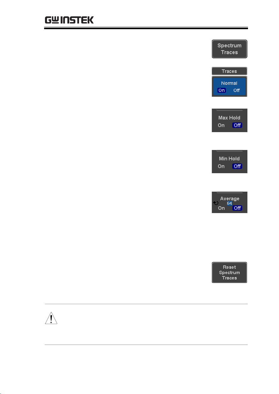
SPECTRUM ANALYZER
253
2. Press the Spectrum Traces button
from the bottom menu.
3. From the side menu, press once on
the Normal button to toggle this
trace option to On. Press again to
toggle it to Off.
4. From the side menu, press once on
the MaxHold button to toggle this
trace option to On. Press again to
toggle it to Off.
5. From the side menu, press once on
the MinHold button to toggle this
trace option to On. Press again to
toggle it to Off.
6. From the side menu, press once on
the Average button to toggle this
trace option to On. Use the variable
knob to change the number of
sweeps the average will be based
on. Press again to toggle it to Off.
Range
2 ~ 256
7. Press the Reset Spectrum Traces
button to clear all current active
traces on the screen and then
restart the spectrum calculation
process.
Note
The four different trace types can be activated at the
same time, allowing a quick comparison for the
maximum, minimum and averaged spectrum
magnitude of the underlying signal.
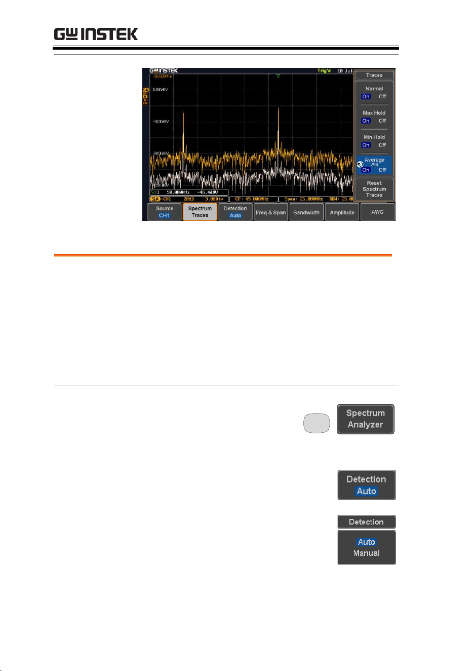
MDO-2000E series User Manual
254
Example
Setting the Detection Method
Background
Each time the Spectrum Analyzer samples data, a
number of samples are usually taken for each
point to display, known as a sample bucket. The
actual value of each point is determined by the
detection method.
Each trace type (Normal, Max and Min Hold,
Average) can use a different detection method.
Panel Operation
1. Press the Option key, and
the Spectrum Analyzer
button to enter the
Spectrum Analyzer menu.
Option
2. Press the Detection button from the
bottom menu.
3. By default, the detection method is
set to Auto. When selected, the
analyzer automatically chooses a
detection method suitable for each
type of trace.
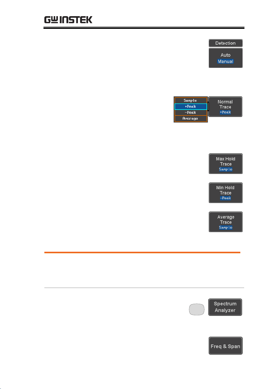
SPECTRUM ANALYZER
255
4. Press the button Auto/Manual once
to toggle the detection method to
Manual and be able to fine tune the
detection method for each type of
trace. Press the Auto/Manual button
once more to toggle it back to Auto.
5. Press on the Normal
Trace button to see a
list of detection
options. Use the
variable knob and the
Select key to select one.
6. Repeat the same operation for the
Max Hold Trace button.
7. Repeat the same operation for the
Min Hold Trace button.
8. Repeat the same operation for the
Average Trace button.
Configuring the Frequencies and Span
Center Frequency
The Center Frequency function sets the center
frequency. The display will be centered on this
frequency.
Panel Operation
1. Press the Option key, and
the Spectrum Analyzer
button to enter the
Spectrum Analyzer menu.
Option
2. Press the Freq & Span button to
enter the frequencies and span
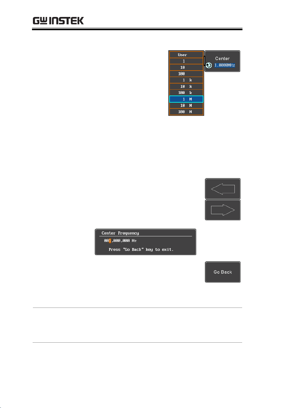
MDO-2000E series User Manual
256
menu.
3. Press the Center button
to display a list of
frequencies step-
resolution.
The variable knob can
be used to select one.
Press again on the
Center button; the
variable knob can now
be used to set the
frequency in
increments of the
chosen step resolution.
4. Alternatively, select User from the
list of frequency or press the Select
key. Use the arrows to select a base
unit and the variable knob to
further tune the selected base unit.
Press Go Back to return to the
previous menu and validate the
user-defined value.
Range
0Hz ~ 500MHz
Span
The Span function sets the frequency range of the
sweep. The sweep will be centered around the
center frequency.
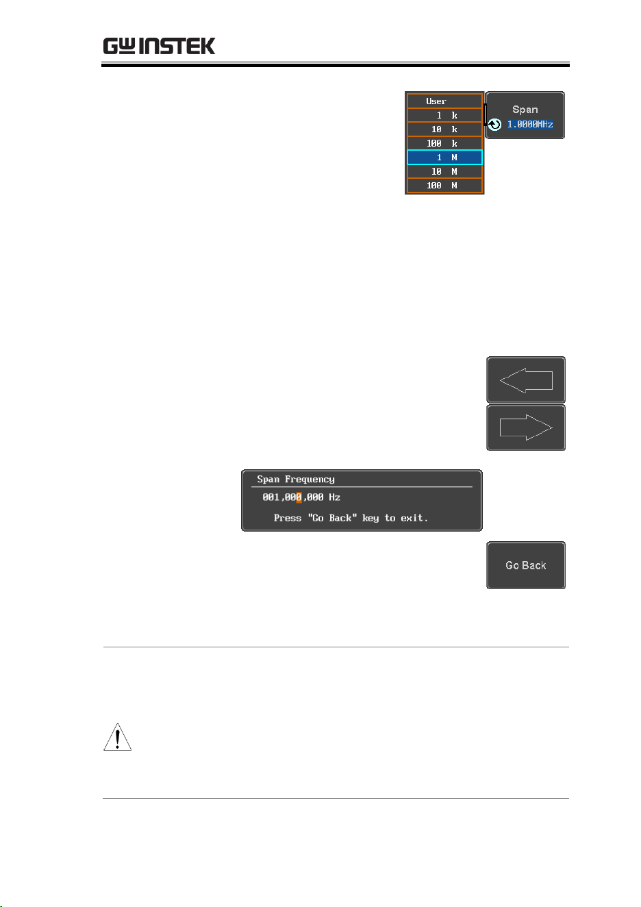
SPECTRUM ANALYZER
257
Panel Operation
5. Press the Span button
to display a list of
frequencies step-
resolution.
The variable knob can
be used to select one.
Press again on the Span
button; the variable
knob can now be used
to set the frequency in
increments of the
chosen step resolution.
6. Alternatively, select User from the
list of frequency or press the Select
key. Use the arrows to select a base
unit and the variable knob to
further tune the selected base unit.
Press Go Back to return to the
previous menu and validate the
user-defined value.
Range
1,000Hz ~ 500MHz
Start and Stop
Frequencies
The Start and Stop frequencies can also be used to
specify the span frequency.
Note
The Start and Stop frequencies are automatically
adjusted when configuring the Center and the Span.
Conversely, configuring the Start and Stop frequencies
will automatically configure the Center and the Span.
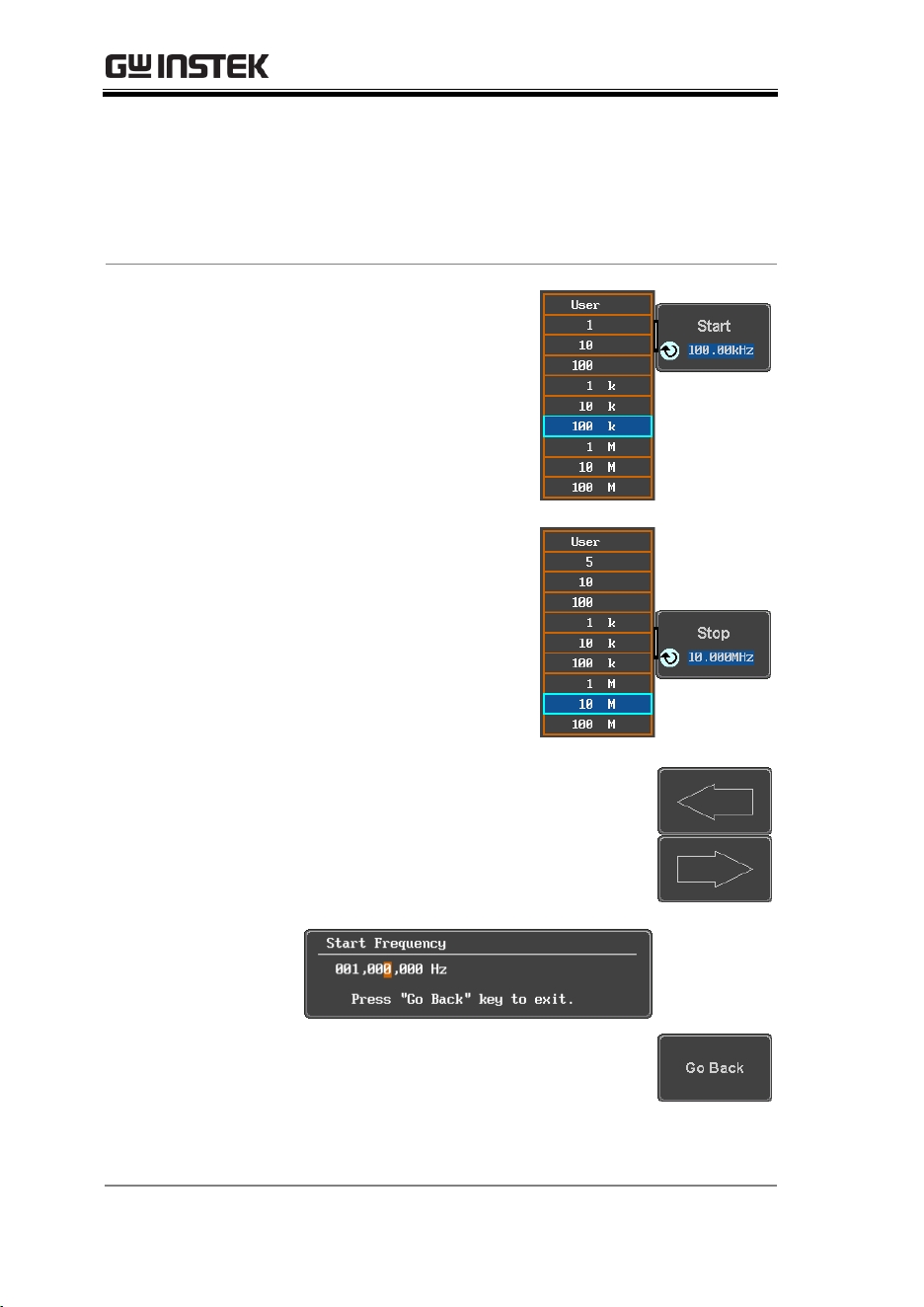
MDO-2000E series User Manual
258
The Stop frequency must always be higher than the
Start frequency. As a consequence, when one crosses
the other’s value, the Start or Stop frequency will
automatically be adjusted to the next highest/smallest
step.
Panel Operation
7. Press the Start or Stop
button to display a list
of frequencies step-
resolution.
The variable knob can
be used to select one.
Press again on the Start
or Stop button; the
variable knob can now
be used to set the
frequency in
increments of the
chosen step resolution.
8. Alternatively, select User from the
list of frequency or press the Select
key. Use the arrows to select a base
unit and the variable knob to
further tune the selected base unit.
Press Go Back to return to the
previous menu and validate the
user-defined value.
Range
Start: -250MHz ~ 499.995MHz
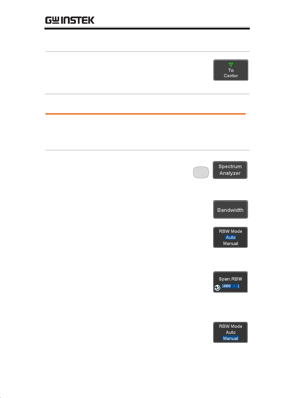
SPECTRUM ANALYZER
259
Stop: 500Hz ~ 750MHz
Span: 1kHz ~ 500MHz
Peak to center
Pressing this button will set the
frequency location of the spectrum
peak as the new center frequency of
the Spectrum Analyzer.
Configuring the Bandwidth
Background
The bandwidth menu gives the possibility of
configuring the resolution bandwidth as well as
the type of window used for the spectral analysis.
Panel Operation
1. Press the Option key, and
the Spectrum Analyzer
button to enter the
Spectrum Analyzer menu.
Option
2. Press the Bandwidth button to enter
the bandwidth menu.
3. The resolution bandwidth can be
set automatically according to a
configurable ratio defined between
the span and the frequency
resolution. To choose that option,
set the RBW Mode button to Auto,
press on the Span: RBW button and
tune the ratio using the variable
knob.
Range
5,000:1 ~ 1,000:1
4. Alternatively, set the RBW. Mode
button to Manual to manually
configure the frequency resolution.
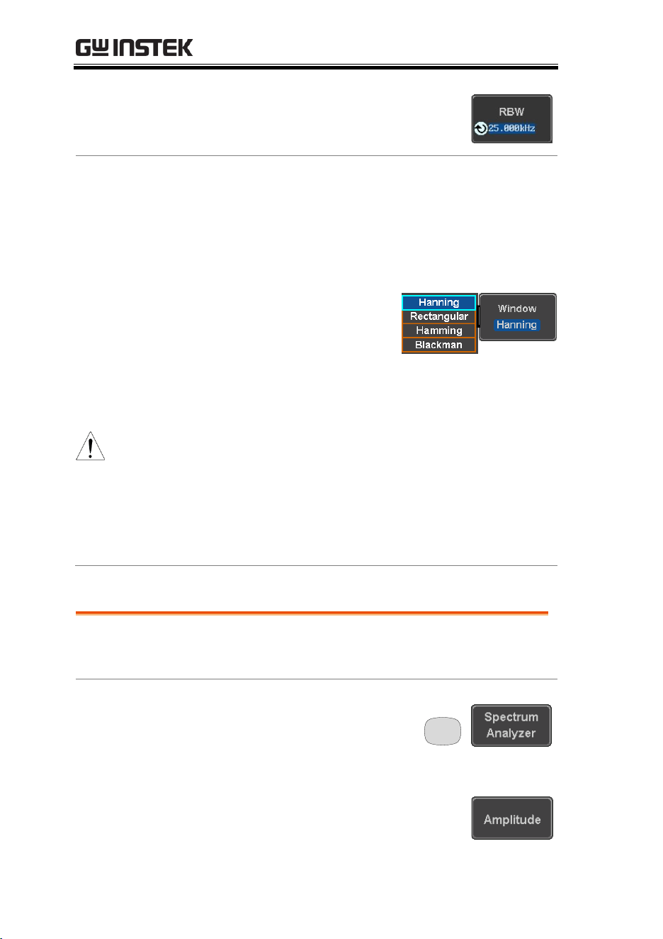
MDO-2000E series User Manual
260
5. Press the RBW button to select the
RBW frequency. The variable knob
can be used to select.
Window type
The type of window used for spectrum analysis
can be chosen. Each window type is characterized
by making a tradeoff between the frequency
resolution and the amplitude accuracy. Please see
the note below.
6. Press the Window button
and change the window
type using the variable
knob. Press again the
Window button to
confirm the change.
Note
Hanning and Hamming windows are both good to
analyze periodic signals. The rectangular window is
more suitable for single shot phenomenon. The
Blackman window is most suitable for amplitude
measurement on periodic signals. Please refer to the
MDO-2000EG/2000EX User Manual
, Math operations,
FFT Overview
for more details.
Configuring the Amplitude
Background
The vertical scale and the zero reference position
can be configured in this menu.
Panel Operation
1. Press the Option key, and
the Spectrum Analyzer
button to enter the
Spectrum Analyzer menu.
Option
2. Press the Amplitude button to enter
the vertical scale menu.
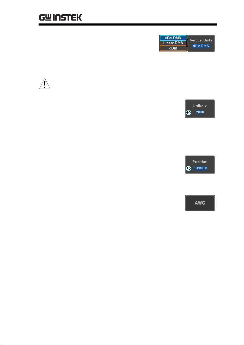
SPECTRUM ANALYZER
261
3. Choose a vertical unit by
toggling the Vertical
Units button to dBV
RMS, Linear RMS or dBm
using the variable knob.
Note
When the setting unit is dBm, connect a 50 Ohm feed
through termination on BNC.
4. You can define the scale of the
vertical axis by pressing on the
Unit/div button and using the
variable knob.
Range
1dB ~ 20dB (dBV RMS, dBm)
2mV ~ 1kV (Linear RMS)
5. You can define the zero level
position by pressing on the Position
button and using the variable knob.
Range
-12.00 ~ 12.00 Div
6. AWG fast switch button. This
button is used for user to observe
the AWG waveform change easily
in the spectrum after changing
waveform parameters.
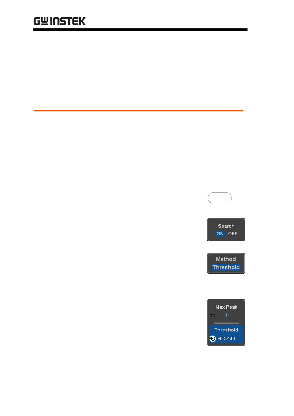
MDO-2000E series User Manual
262
Measurement
The Spectrum Analyzer of the MDO-2000E is compatible with a
certain number of measurement tools such as the search function
and the use of cursors, enabling detailed analysis of the signal
characteristics in the frequency domain.
Using the Search function
Background
When the Spectrum Analyzer is on, pressing the
Search key and turning on the Search function will
automatically pre-configure the Search Type and the
Source (respectively set to SP Peak and SP) in order
to search for spectrum peaks. Please also note that
it is not possible to search for spectrum peaks if the
Spectrum Analyzer Option is not on.
Panel Operation
1. When the Spectrum Analyzer is
on, press the Search key.
Search
2. Press the Search button from the
bottom menu to turn the Search
function on.
3. Configure the Search Method by
pressing the Method button from
the bottom menu and choose
between two methods:
Max Peak: search for a defined
number of peaks.
Threshold: search for peaks above
a defined threshold level.
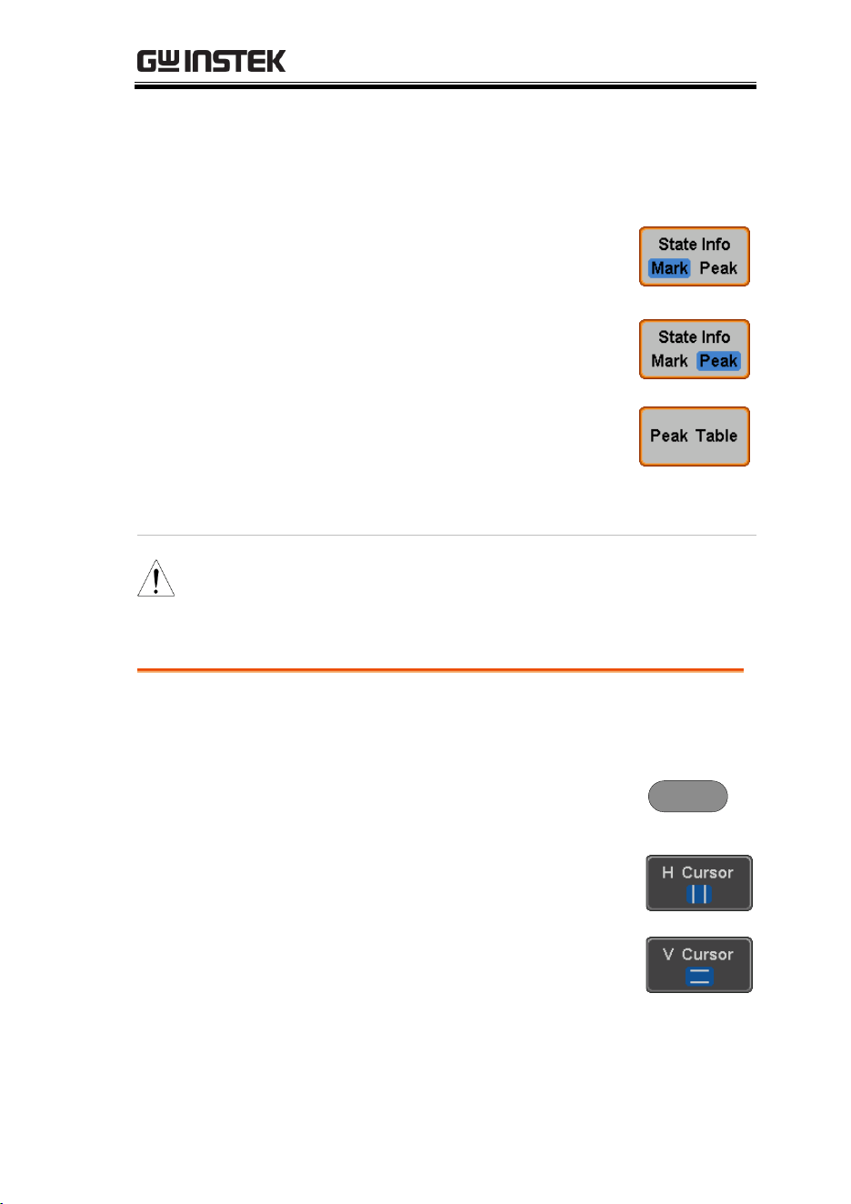
SPECTRUM ANALYZER
263
4. You can configure the Event state
display by toggling the State Info
button either to Mark or to Peak.
Mark: displays the overall number
of peaks and the current active
peak.
Peak: gives frequency and level
details of the current active peak.
5. Press on the Peak Table button
from the bottom menu to examine
all the searched spectrum peaks in
a tabulated form or save it as files
on an external USB drive.
Note
For more details about the Search function, please
refer to the
MDO-2000E User Manual
,
Search
chapter.
Using the Cursors
Background
Horizontal and vertical cursors can be used
together with the Spectrum Analyzer.
Panel Operation
1. When the Spectrum Analyzer is on,
press the cursor key.
Cursor
2. Move the horizontal cursors along
the trace to perform accurate
measurement of frequency and
level. Use the horizontal and
vertical cursors together to further
measure points of interest in both
absolute and delta values.

MDO-2000E series User Manual
264
Note
For more details about the
cursor
function, please
refer to the
MDO-2000E User Manual
,
Cursor
chapter.
Use the Save / Recall menu to save the spectrum data
as a CSV file in SA mode, but you can’t recall the file to
the screen.

DMM
265
DMM
DMM function ..........................................................266
Accessing the Digital Multimeter ...................................................... 266
DMM display overview ....................................................................... 267
AC/DC Voltage Measurement .......................................................... 268
Current Measurement .......................................................................... 269
Resistance Measurement ..................................................................... 270
Diode Measurement ............................................................................. 271
Continuity Measurement ..................................................................... 272
Temperature Measurement ................................................................. 273
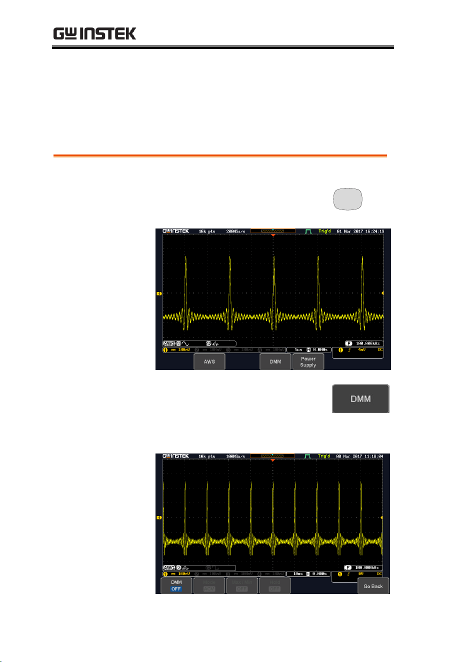
MDO-2000E series User Manual
266
DMM function
The DMM function can be used simultaneously with the DSO
function. The DMM function is a basic digital multimeter.
Accessing the Digital Multimeter
Panel Operation
1. Press the Option key. The following
diagram will appear on the
display.
Option
2. Press the DMM button from the
bottom menu. The following
diagram will appear on the
display.
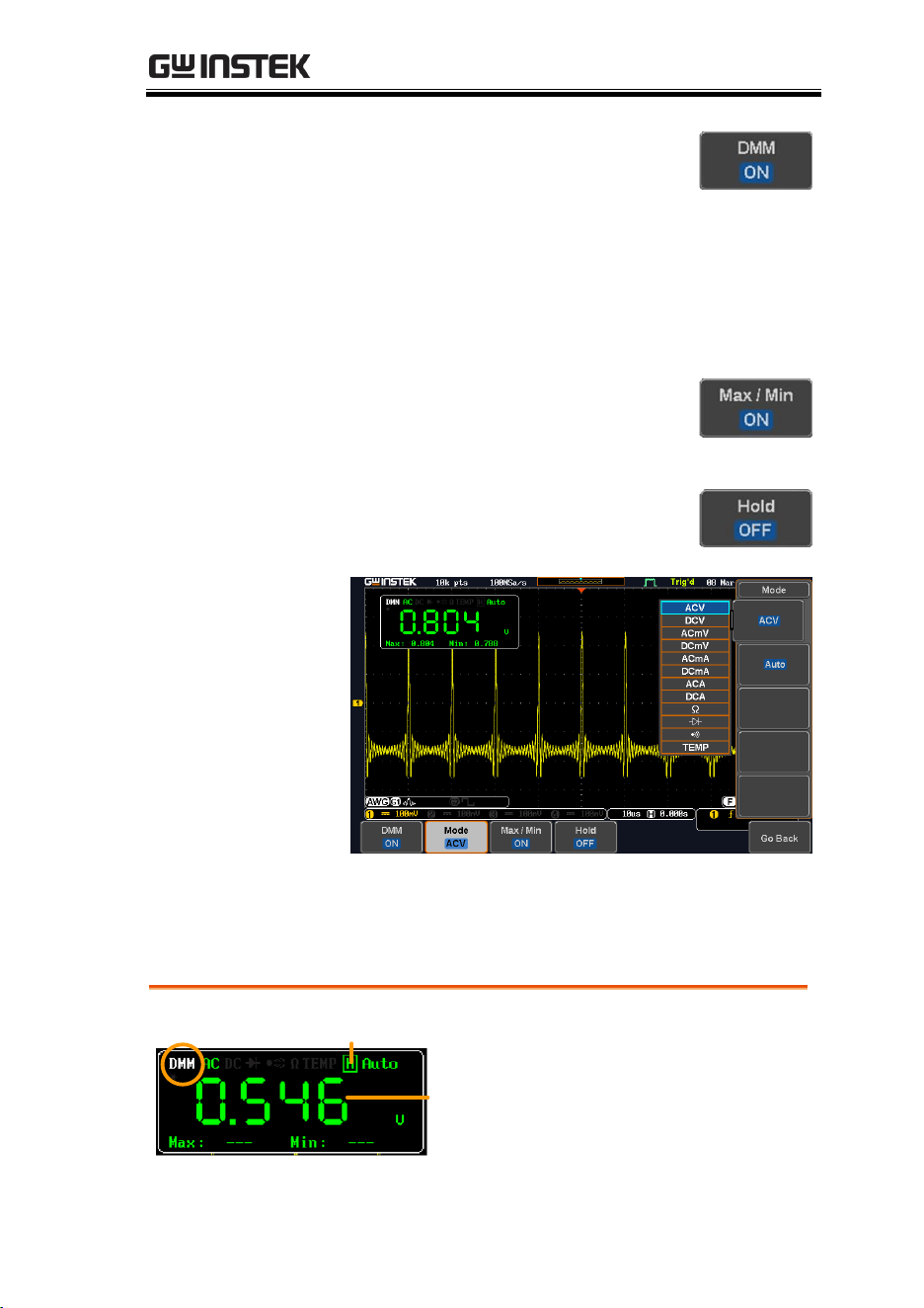
DMM
267
3. Press DMM button from the
bottom menu to turn on the DMM
function. You can select ACV,
DCV, ACmV, DCmV, ACmA,
DCmA, ACA, DCA, Ohms, Diode,
Continuity and Temperature
measurement from the DMM
menu.
4. Press the Max/Min button to
display the measured maximum
and minimum values
5. Press the Hold button to keep the
current measurement results.
DMM display overview
The DMM display will show the measurement mode, max, min and
current measurement.
Current measurement
DMM mode
Max Min
Hold on/off
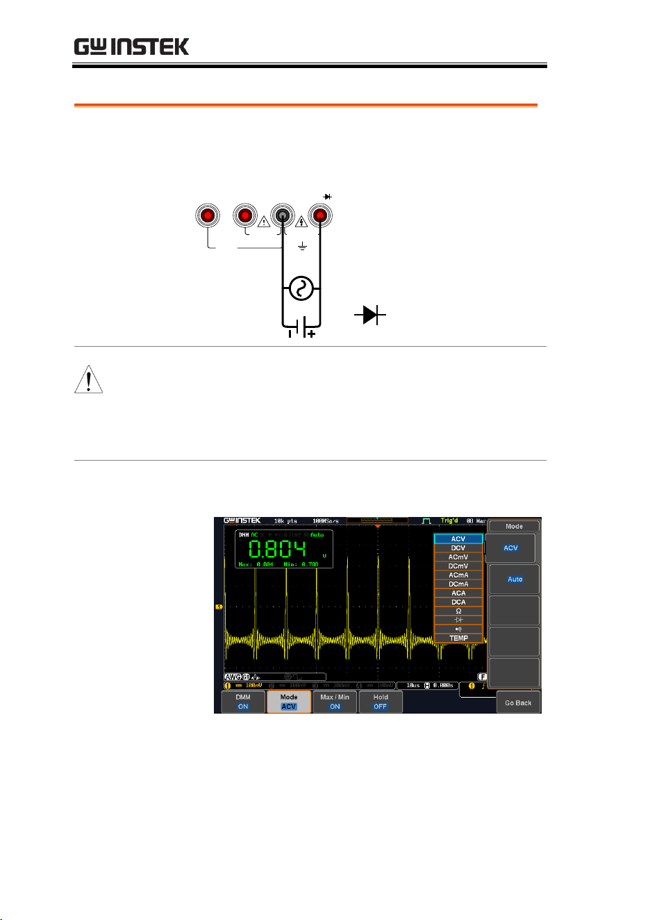
MDO-2000E series User Manual
268
AC/DC Voltage Measurement
Background
The MDO-2000E series can measure up to 600V
(CAT II) or 300V (CAT III).
Connection
10A MAX
FUSED
V
W
COMA mA
COM
W
CAT II 600V
CAT III 300V
FUSED
600mA MAX
V
Note
To prevent the internal circuits from burning out, the
unit will prevent you from switching voltage ranges
during measurement when the input is greater than
10V. To switch ranges, first disconnect the probes
from the DUT.
Steps
1. From the multimeter settings choose ACV,
ACmV, DCV or DCmV.
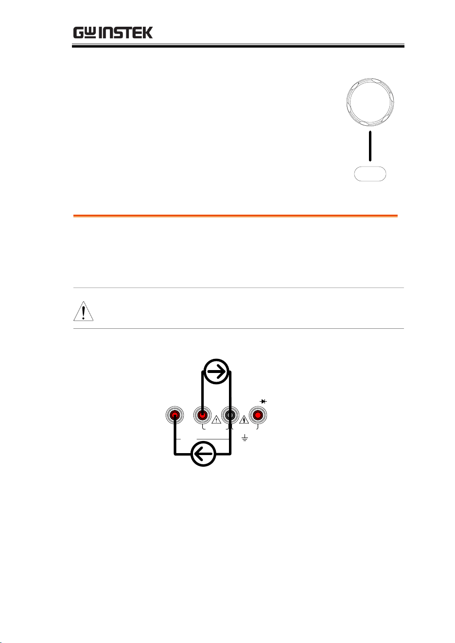
DMM
269
2. Use the Variable knob to select the
required measurement and press
the Select key to confirm.
Select
VARIABLE
Current Measurement
Background
The MDO-2000E can measure AC and DC current
from two input terminals, depending on the
current range. There is a 10A input for I≤10A, and
a mA terminal for I≤600mA.
Note
Ensure that no more than 600mA is input into the mA
port. Failure to do so will blow the fuse.
Connection
10A MAX
FUSED
V
W
COMA mA
Max 10A
Max 600mA
A COM
mA COM
CAT II 600V
CAT III 300V
FUSED
600mA MAX
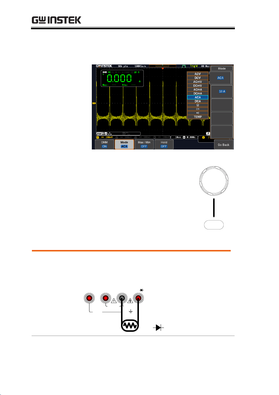
MDO-2000E series User Manual
270
Steps
1. From the multimeter settings choose ACA,
ACmA, DCA or DCmA. Ensure that no more
than the 600mA is input into the mA port.
2. Use the Variable knob to select the
required measurement and press
the Select key to confirm.
Select
VARIABLE
Resistance Measurement
Background
The MDO-2000E can measure resistance up to 4
counts.
Connection
10A MAX
FUSED
V
W
COMA mA
CAT II 600V
CAT III 300V
FUSED
600mA MAX
W
V
COM
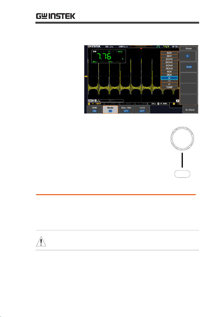
DMM
271
Steps
1. From the multimeter settings choose the
resistance measurement.
2. Use the Variable knob to select the
required measurement and press
the Select key to confirm.
Select
VARIABLE
Diode Measurement
Background
The diode test checks the forward bias
characteristics of a diode by running a constant
forward bias current through the DUT and
measuring the forward voltage drop.
Note
Ensure the diode polarity is correct before performing
the diode measurement.
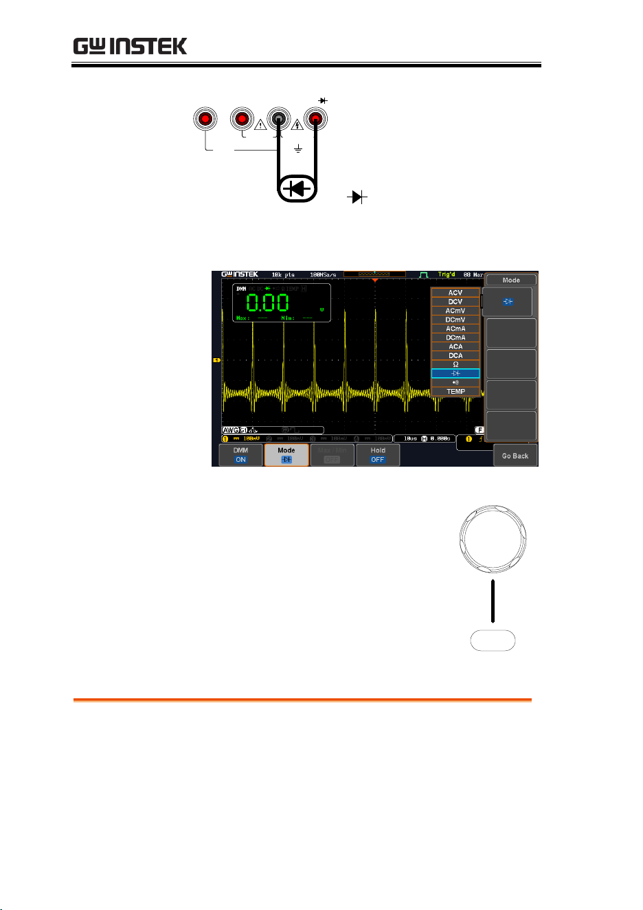
MDO-2000E series User Manual
272
Connection
10A MAX
FUSED
V
W
COMA mA
COM
V
W
CAT II 600V
CAT III 300V
FUSED
600mA MAX
Steps
1. From the multimeter settings choose the diode
measurement.
2. Use the Variable knob to select the
required measurement and press
the Select key to confirm.
Select
VARIABLE
Continuity Measurement
Background
The continuity test checks that the resistance in the
DUT is low enough to be considered continuous
(of a conductive nature). The continuity threshold
level is set to <15Ω.
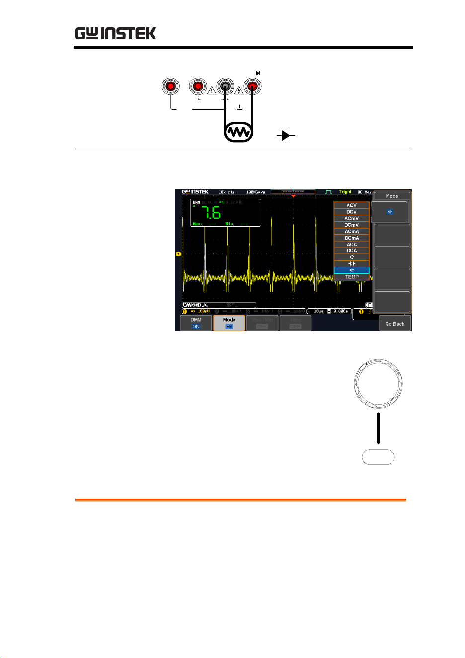
DMM
273
Connection
10A MAX
FUSED
V
W
COMA mA
CAT II 600V
CAT III 300V
FUSED
600mA MAX
W
V
COM
Steps
1. From the multimeter settings choose the
continuity measurement
2. Use the Variable knob to select the
required measurement and press
the Select key to confirm.
Select
VARIABLE
Temperature Measurement
Background
The MDO-2000E series can measure temperature
using a thermocouple. To measure temperature,
the DMM accepts a thermocouple input and
calculates the temperature from the voltage
fluctuation. The thermocouple type is taken into
consideration.
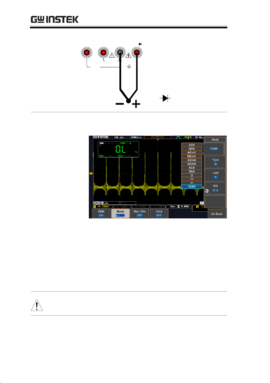
MDO-2000E series User Manual
274
Connection
10A MAX
FUSED
V
W
COMA mA
COM
V
W
CAT II 600V
CAT III 300V
FUSED
600mA MAX
Steps
1. From the multimeter settings choose the
temperature measurement.
2. Select the thermocouple type. Thermocouple =
B E, J, K, N, R, S, T
3. Pressing the Unit button will toggle between ºC
and ºF.
4. SIM is the current ambient temperature setting,
ranging from 0.00 to 50.0.
Note
Please see the specifications on page 366 for the
thermocouple specifications.

POWER SUPPLY
275
POWER SUPPLY
Power supply function ..............................................276
Accessing the Power Supply ............................................................... 276
Set up the Power Supply ..................................................................... 278
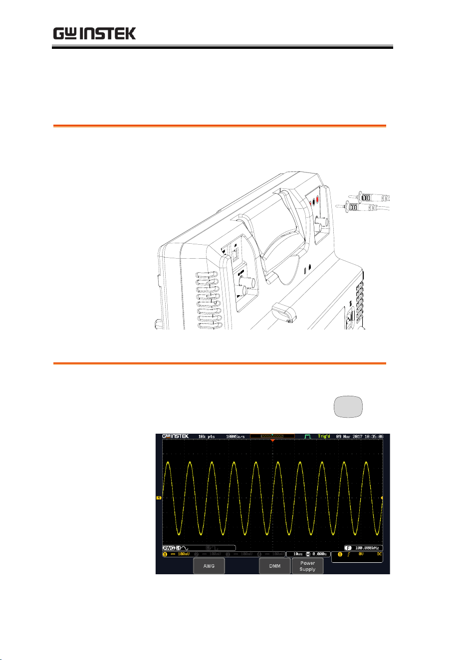
MDO-2000E series User Manual
276
Power supply function
The function can supply continuously adjustable DC power output
to dual channels with 1 ~ 5V voltage (1A max).
Connection
1. Connect the test leads for power supply to the
power supply output 1 or 2.
Red
Black
Accessing the Power Supply
Panel Operation
1. Press the Option key. The following
diagram will appear on the display.
Option
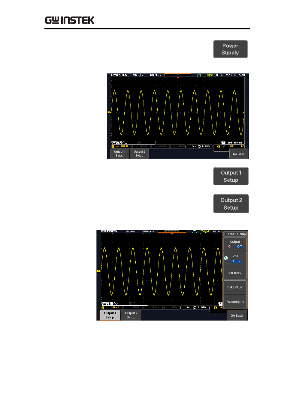
POWER SUPPLY
277
2. Press the Power Supply button from
the bottom menu. The following
diagram will appear on the display.
3. Select Output setup 1 or Output
setup 2 button to set and turn on the
power supply. For example, press
the Output setup 1button. The
following diagram will appear on
the display.
or
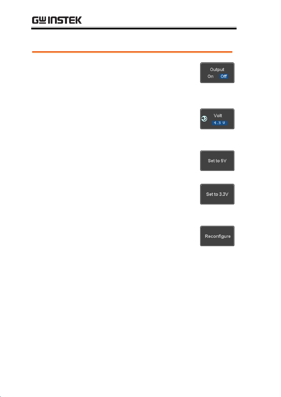
MDO-2000E series User Manual
278
Set up the Power Supply
Panel Operation
1. Set the output on or off
Press the Output On/off button to
turn on off the power supply.
2. Select output voltage range
Press the Volt button to select
output continuously adjustable
voltage from 1V to 5V (0.1 step)
3. Set to 5V
Press the Set to 5Vbuttonto directly
set the output voltage to 5V.
4. Set to 3.3V
Press the Set to 3.3Vbuttonto
directly set the output voltage to
3.3V.
5. When output is more than 1A or
short circuit, OCP will be directly
turned on. Press the Reconfigure
button to reset and return to
normal output.

APPLICATIONS
279
APPLICATIONS
Introduction .............................................................280
Overview ................................................................................................ 280
Running Applications .......................................................................... 281
Go-NoGo application ................................................282
DVM application .......................................................287
Data Log application .................................................289
Digital Filter application ...........................................291
Mask application ......................................................293
Select the source channel .................................................................... 293
Configure the mask violation ............................................................. 293
Auto Mask ............................................................................................. 294
User Defined Mask / Create Mask ................................................... 298
User-defined Mask File Format ......................................................... 301

MDO-2000E series User Manual
280
Introduction
Overview
Background
The Application (APP) function allows different
software applications to be run. The MDO-2000E
comes pre-installed with a number of apps, as
described below. Please see your local GW Instek
distributor for the latest information on new apps.
Included
Applications
Go/No-Go
The Go/No-Go application can be
used to set threshold boundaries
for input signals. Go/No-Go tests
to see if a waveform will fit inside
a user-specified maximum and
minimum amplitude boundary
(template).
DVM
The DVM application displays a
digital voltage meter readout that
floats on the top left-hand side of
the screen.
Data Log
The Data Log app will log
waveform data and/or
screenshots at set intervals for set
duration of time.
Digital Filter
Adds a digital low, high or band
pass filter to any of the input
channels. Each filter can have a
user-defined cutoff frequency set.
Mask
Create shape templates for signal
comparison.
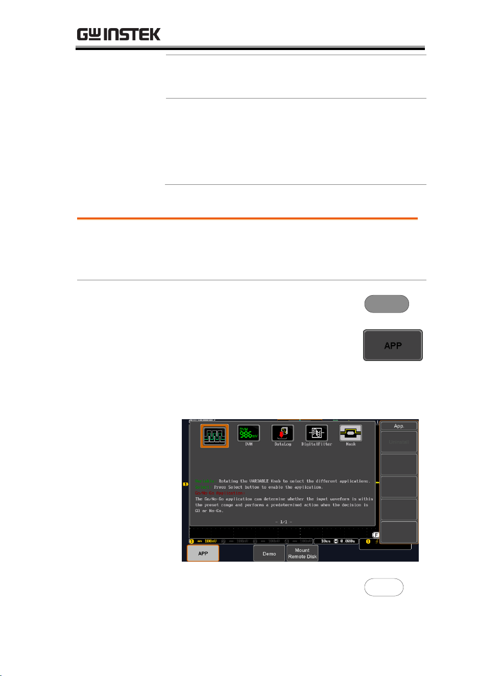
APPLICATIONS
281
Mount Remote
Disk
This app allows the scope to
mount a network share drive.
Demo
The Demo app, when combined
with the GDB-03 demo board,
allows the scope to trigger a
number of different signals from
the demo board.
Running Applications
Background
The MDO-2000E comes pre-installed with a
number of apps which can be activated from a
dedicated menu.
Panel Operation
1. Press the APP key.
APP
2. Press APP from the bottom menu.
3. Scroll through each application using the
Variable knob.
4. Select an application by pressing
the Select key twice.
Select
×2
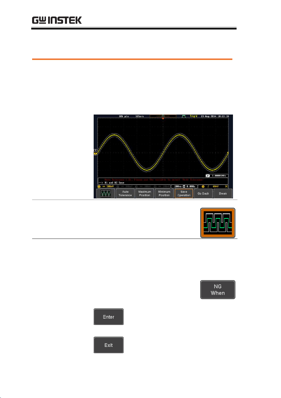
MDO-2000E series User Manual
282
Go-NoGo application
Background
The Go-NoGo test checks if a waveform fits inside
a user-specified maximum and minimum
boundary. Boundary templates are automatically
created from a source channel. Boundary
tolerances and violation conditions can be set.
Choose the Go_NoGo application
from the APP menu. See page 281.
Set Go-NoGo
Conditions
Select the Go-NoGo conditions (NG When) and
actions when a Go-NoGo condition has been met
(Violating).
1. Press NG When from the bottom
menu and select the NoGo
conditions:
Enter: Sets the NoGo condition to
when the input signal stays within
the limit boundary.
Exit: Sets the NoGo condition to
when the input signal exceeds the
limit boundary.
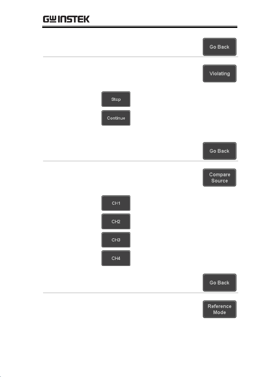
APPLICATIONS
283
2. Press Go Back to return to the
previous menu.
Set Go-NoGo
Actions
3. Press Violating to set what action to
perform when a signal violates the
Go-NoGo conditions.
The waveform stops when the
conditions are violated.
Ignore violations and continue to
monitor the signal. Each violation is
counted.
4. Press Go Back to return to the
previous menu.
Set Go-NoGo
Source
5. Press Compare Source from the
bottom menu to set the Go-NoGo
boundary source.
Sets CH1 as the source.
Sets CH2 as the source.
Sets CH3 as the source.
Sets CH4 as the source.
6. Press Go Back to return to the
previous menu.
Set Boundary
Tolerance
7. To set the Go-NoGo boundary
tolerance, press Reference Mode.
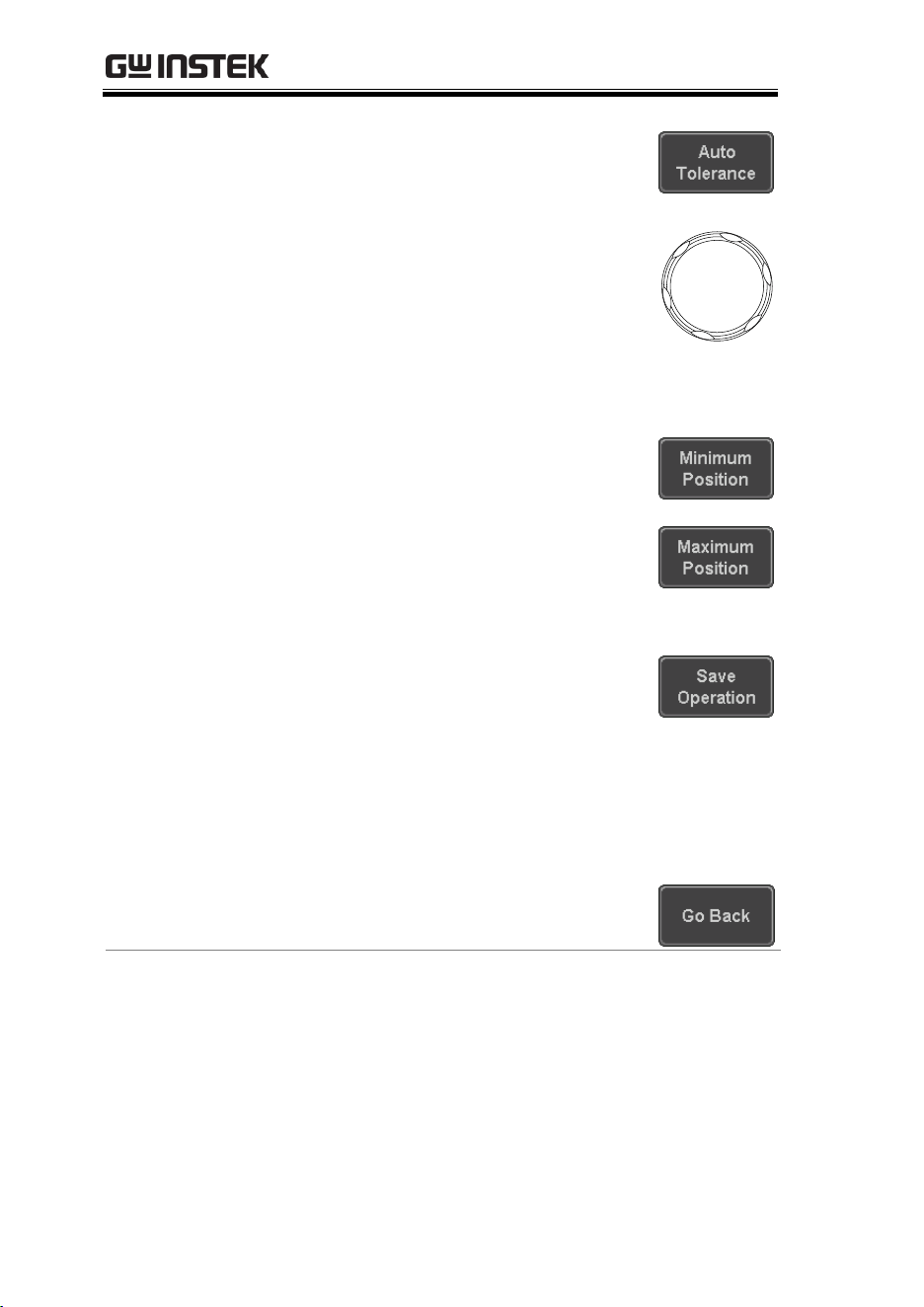
MDO-2000E series User Manual
284
Auto Tolerance
8. To set the boundary tolerance as a
percentage offset from the source
waveform, press Auto Tolerance
and use the Variable knob.
VARIABLE
Offset
0.4% ~ 40% (.4% steps)
Maximum and
Minimum
Position
9. To manually set the template
tolerance, press Minimum Position
or Maximum Position and use the
Variable knob to set the absolute
minimum or maximum position.
or
Range
Voltage division range
Save Boundary
Template
10. Press Save Operation to save the
tolerance boundaries.
11. The Maximum Position tolerance
will be saved to reference
waveform R1, and the Minimum
Position tolerance to R2.
12. Press Go Back to return to the
previous menu.
Start Go-NoGo
Press Enable to start the Go-NoGo test. Then the
Enable button will change to Disable. Pressing
Disable will stop the Go-NoGo test and toggle the
button back to Enable.
If the Violating setting was set to Stop, press Enable
to restart the test after it has stopped.
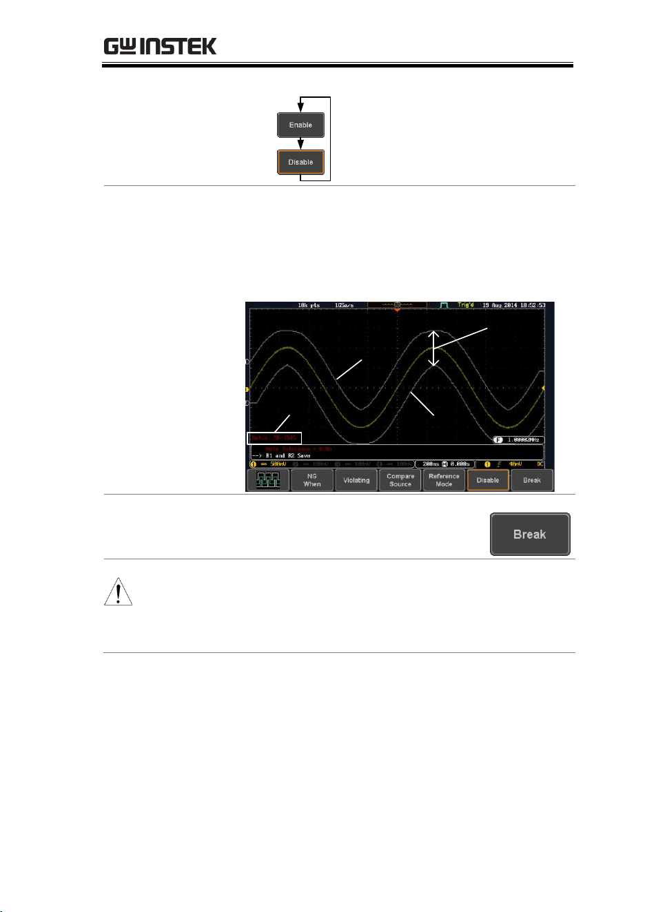
APPLICATIONS
285
Start test
Stop test
Test
stopped
Results
When Go-NoGo is running, the violation/test ratio
is displayed in the bottom left-hand corner. The
first digit represents the number of violations, and
the right hand digit represents the number of tests.
Ratio:
violation / test
Maximum
position
Minimum
position
Tolerance
Exit the
Application
To exit the application, press Break.
Note
After you exit the Go/NoGo app, the boundary
templates that were saved to R1 & R2 reference
waveforms will still be turned on. See page 327 to turn
the reference waveforms off.
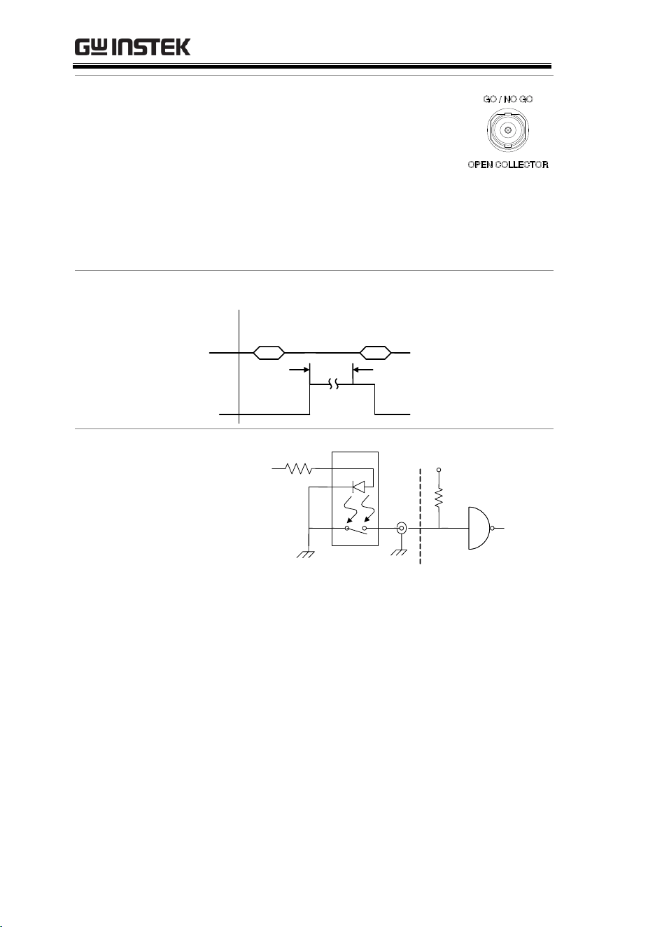
MDO-2000E series User Manual
286
Using the Go-
NoGo Output
To output the Go-NoGo results to an
external device, the Go-NoGo rear
panel terminal (open collector) can be
used. The Go-NoGo terminal will
output a positive pulse each time a
NoGo violation has occurred for a
minimum of 500us. The voltage of the
pulse depends on the external pull-up
voltage.
Timing Diagram
Enable
NoGo
500
us
Waveform
Circuit Diagram
Go-NoGo signal
220
Ω
Go-NoGo
BNC
B
+
CMOS
(Max 16V)
Or TTL
(Max 5V)
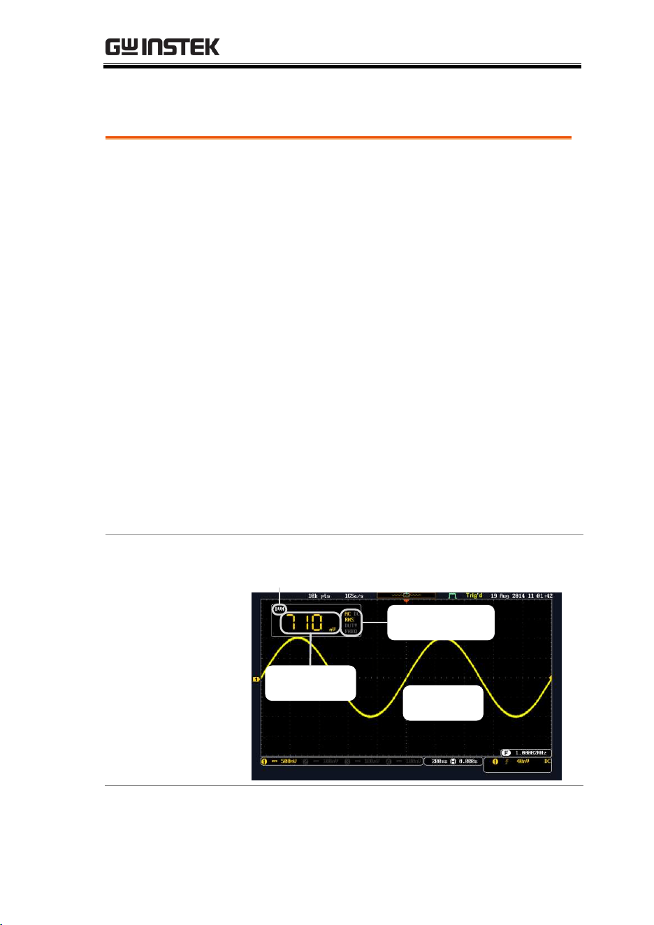
APPLICATIONS
287
DVM application
Background
The DVM app is a digital voltage meter or digital
current meter readout that floats on the top left-
hand side of the screen. However, please note that
if the cursors (refer to page 60) are turned on, the
DVM readout will be replaced by the cursor
readout.
The DVM app allows you to measure the AC RMS,
DC, DC RMS, Duty and frequency of an input
signal. This software is especially useful for those
measurement applications that require both a DSO
and a basic DVM to be used at the same time.
Basic Features:
300V input (peak AC + DC) CAT 1
3 digit resolution for voltage measurements
5 digit resolution for frequency
Input channel selection
Example
DVM function
indicator
Source
Waveform
Measurement
and unit
Measurement
mode
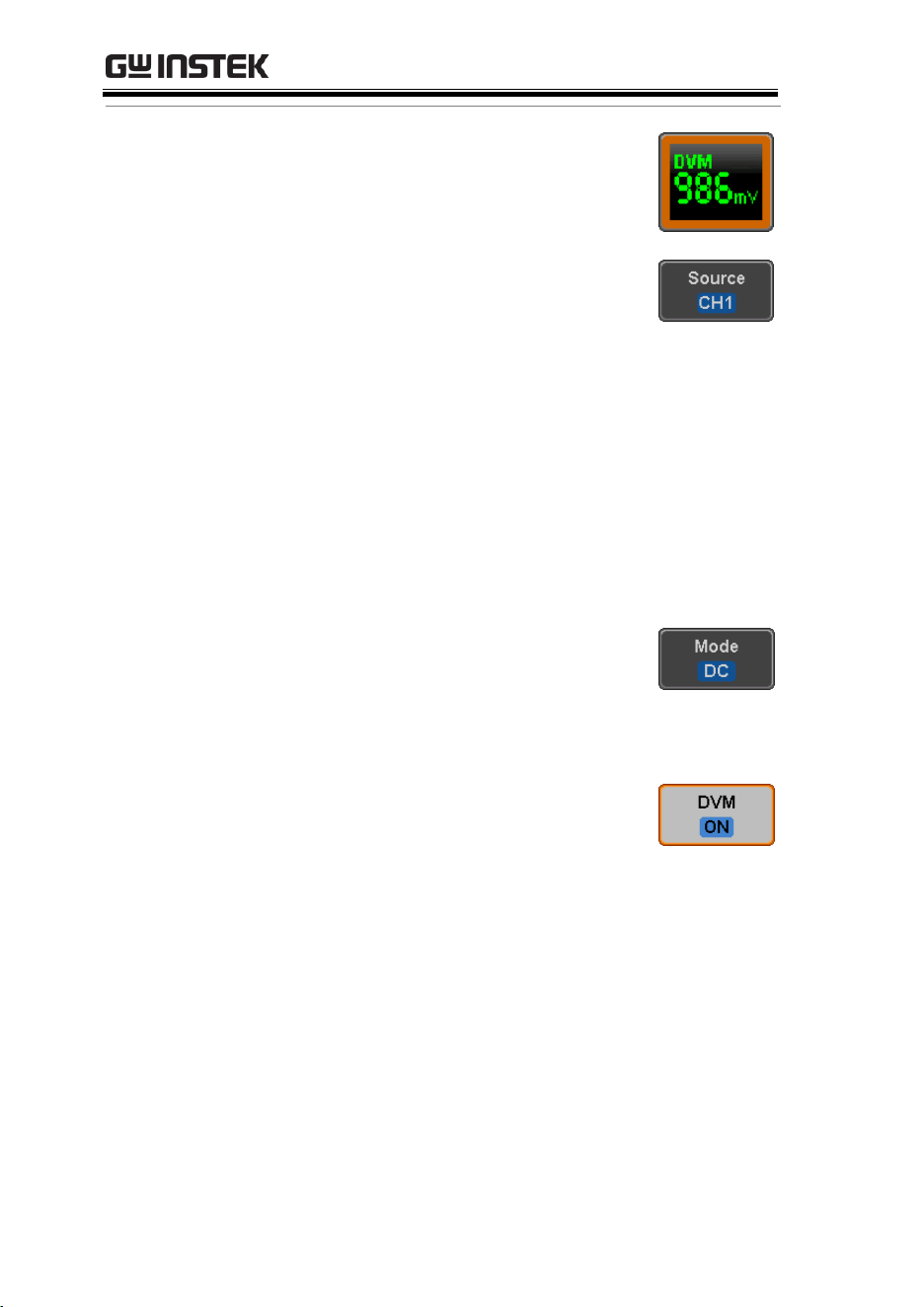
MDO-2000E series User Manual
288
Panel Operation
Choose the DVM application from the
APP menu. See page 281.
Set Source
1. Press Source and select the source
channel for the DVM. The probe
type setting (voltage or current)
determines whether the function
acts as a digital voltmeter or as a
digital current meter for the
selected source. See page 115 to set
the probe type.
Source
CH1 ~ CH4
Mode
The Mode setting determines the measurement
mode for the meter.
2. Press Mode and select the mode.
Mode
AC RMS, DC, DC RMS, Duty,
Frequency
Turn On/Off
3. Press DVM and toggle DVM on.
The DVM app will remain running
in the background even if other
functions are turned on.
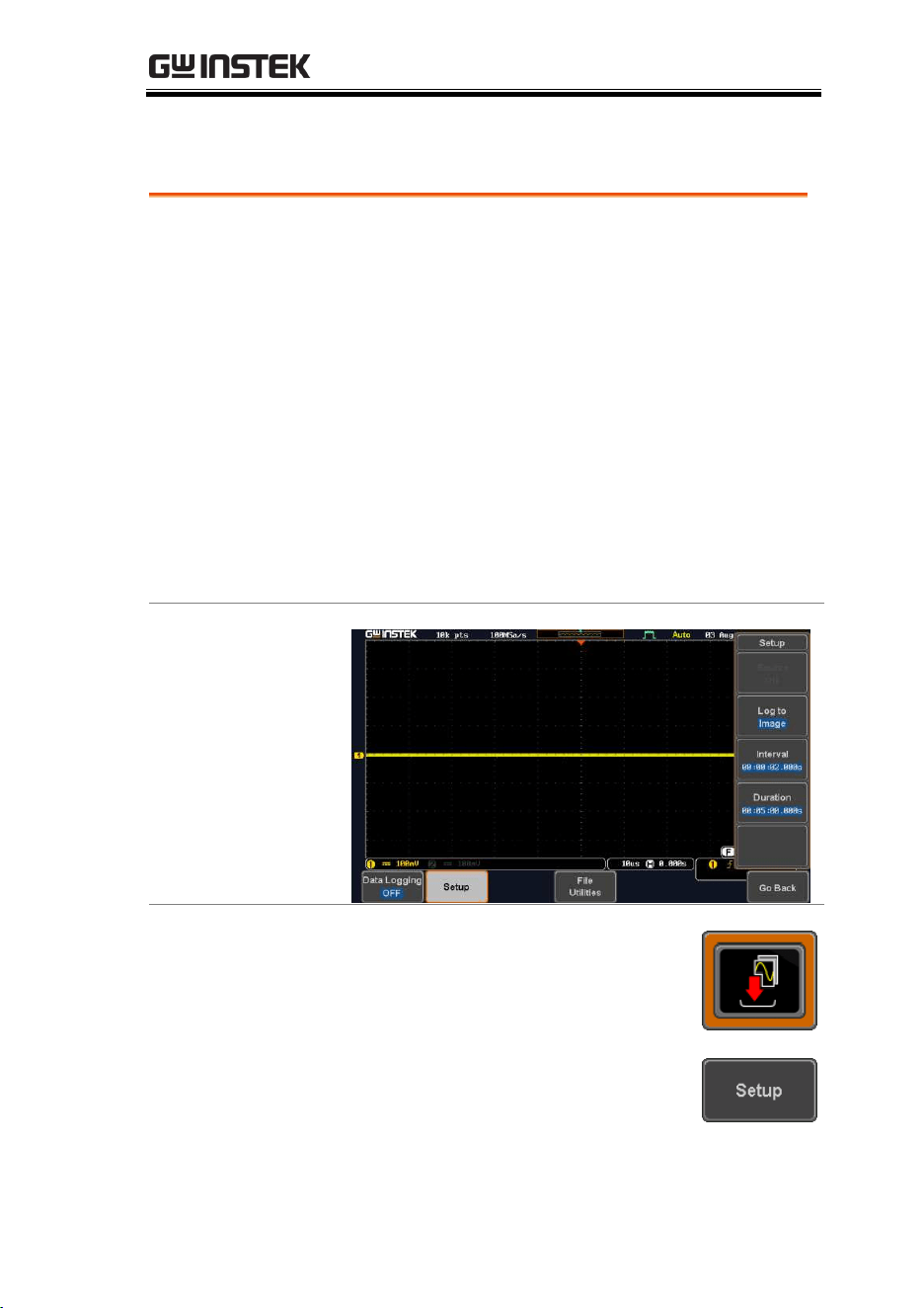
APPLICATIONS
289
Data Log application
Background
The Data Log app will log the current waveform
data or screenshot at set intervals for a set duration
of time.
Basic Features:
Log up to 1000 hours of images or waveform
data.
The minimum interval is 2, or 5 seconds, and
the Interval time needs to be lengthened
because of the longer memory length. If you
use the USB flash drive to store data, it may
require a longer interval which depends on
the storing data speed of the USB flash drive.
Example
Panel Operation
Choose the Data Log application from
the APP menu. See page 281.
1. Press Setup.
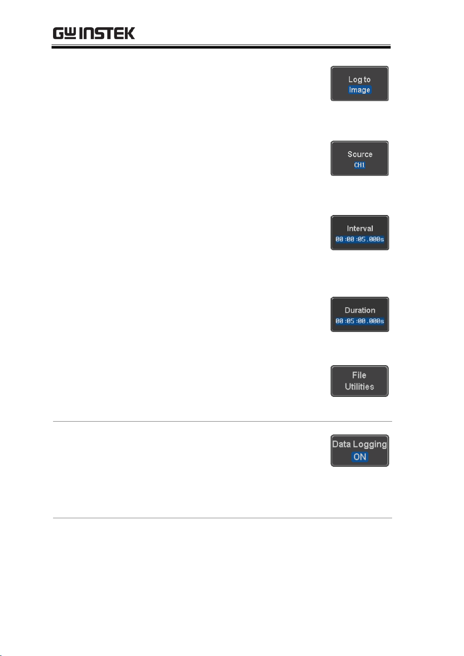
MDO-2000E series User Manual
290
2. Press Log to from the side menu
and select what type of data to log,
waveform data or screenshots.
Log to
Image, Waveform
3. Press Source from the side menu
and select a source channel to log if
waveforms are to be logged.
Source
CH1 ~ CH4, All Displayed
4. Press Interval and set the logging
interval time.
Interval
Data: 2sec ~ 23h59m59.5s
Image: 5sec ~ 23h59m59.5s
5. Press Duration and select the
logging duration time.
Duration
5sec ~ 999h59m59.5s
6. From the bottom menu, press File
Utilities and set the save file path.
See the File Utilities chapter (page
329) for details.
Turn On/Off
7. Press Data Logging from the bottom
menu and toggle Data Logging on.
The data/images will be saved to
the designated file path when Data
Logging is turned on.
Set File Path
8. Press File Utilities to set the file
path.
Page 329
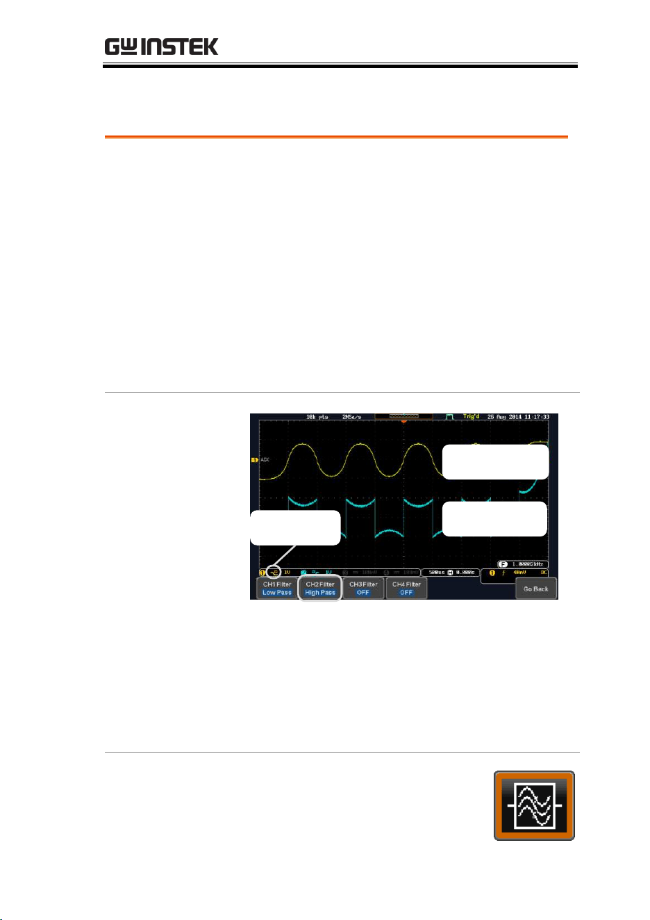
APPLICATIONS
291
Digital Filter application
Background
The Digital Filter app is a digital high, low, band
pass filter with a selectable cutoff frequency. The
digital filter can be applied to analog channel
individually or together using the tracking
functionality.
Basic Features:
high, low, band pass filtering of analog
channels.
Selectable cutoff frequencies.
Tracking function
Example
Digital filter
type or status
High pass filter
example
Digital filter
indicator
Low pass filter
example
CH1 input: 2Vpp 1kHz square wave, low pass filter
with 1kHz cutoff frequency.
CH2 input: 2Vpp 1kHz square wave, high pass
filter with 1kHz cutoff frequency.
Panel Operation
Choose the Digital filter application
from the APP menu. See page 281.
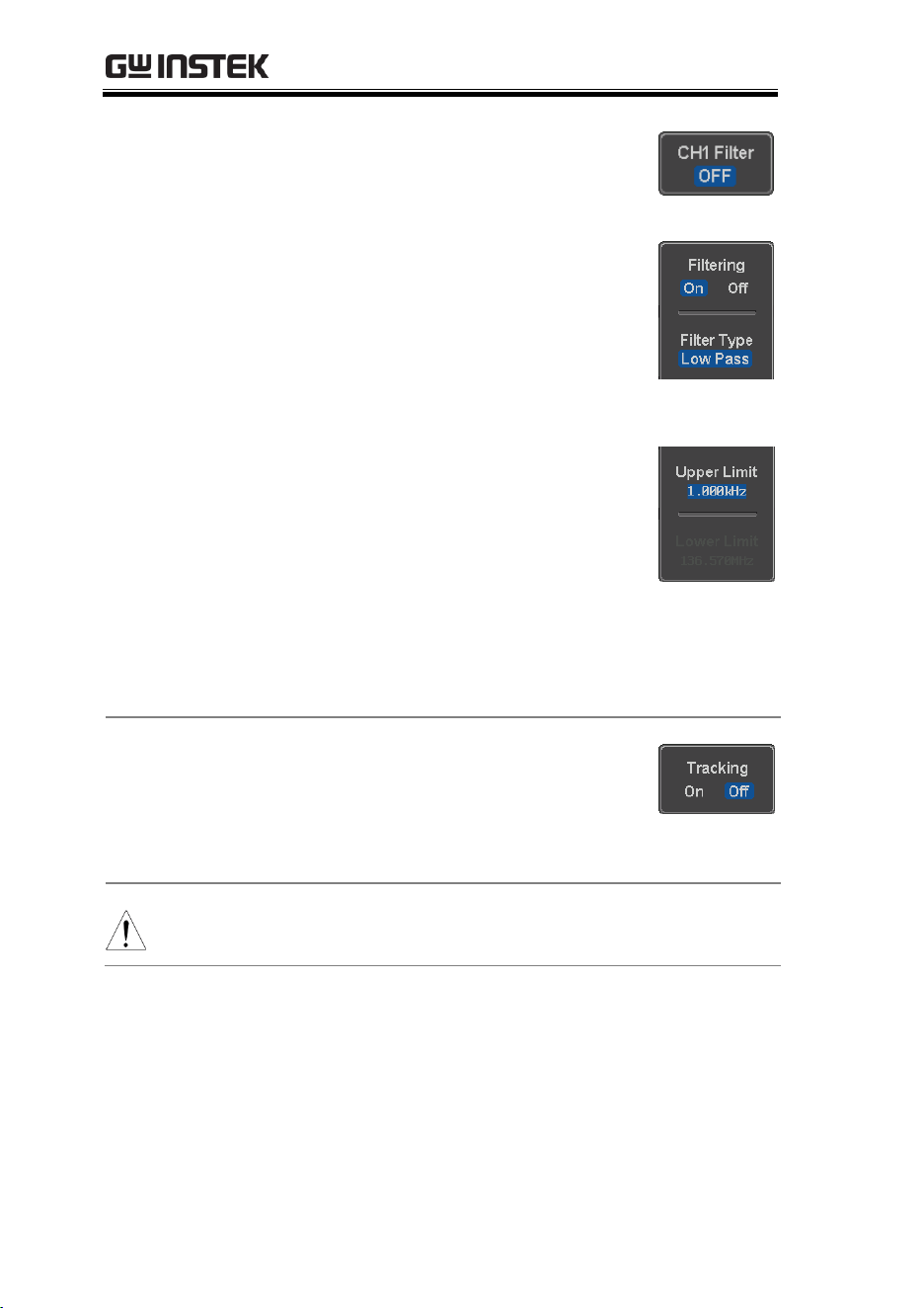
MDO-2000E series User Manual
292
Set Source
1. Select a source channel by pressing
CH1Filter, CH2 Filter, CH3 Filter or
CH4 Filter.
2. From the side menu press Filtering
and turn on.
3. Press Filter Type and select low,
high, or band
pass filter.
Type
Low Pass, High Pass, Band Pass
4. If Low Pass was selected, press
Upper Limit to set the low pass
cutoff frequency. Likewise if High
Pass was selected, press Lower
Limit to set the high pass cutoff
frequency. Only one option will be
available at a time.
Upper Limit
1Hz ~ 500MHz
Lower Limit
1Hz ~ 500MHz
Tracking
5. Press Tracking if you want the
settings of the digital filter on each
channel to be the same. When a
setting is changed on one channel,
it is reflected on the other channels.
Note
The digital filter settings will still apply to the relevant
input signals after leaving the app, unless turned off.
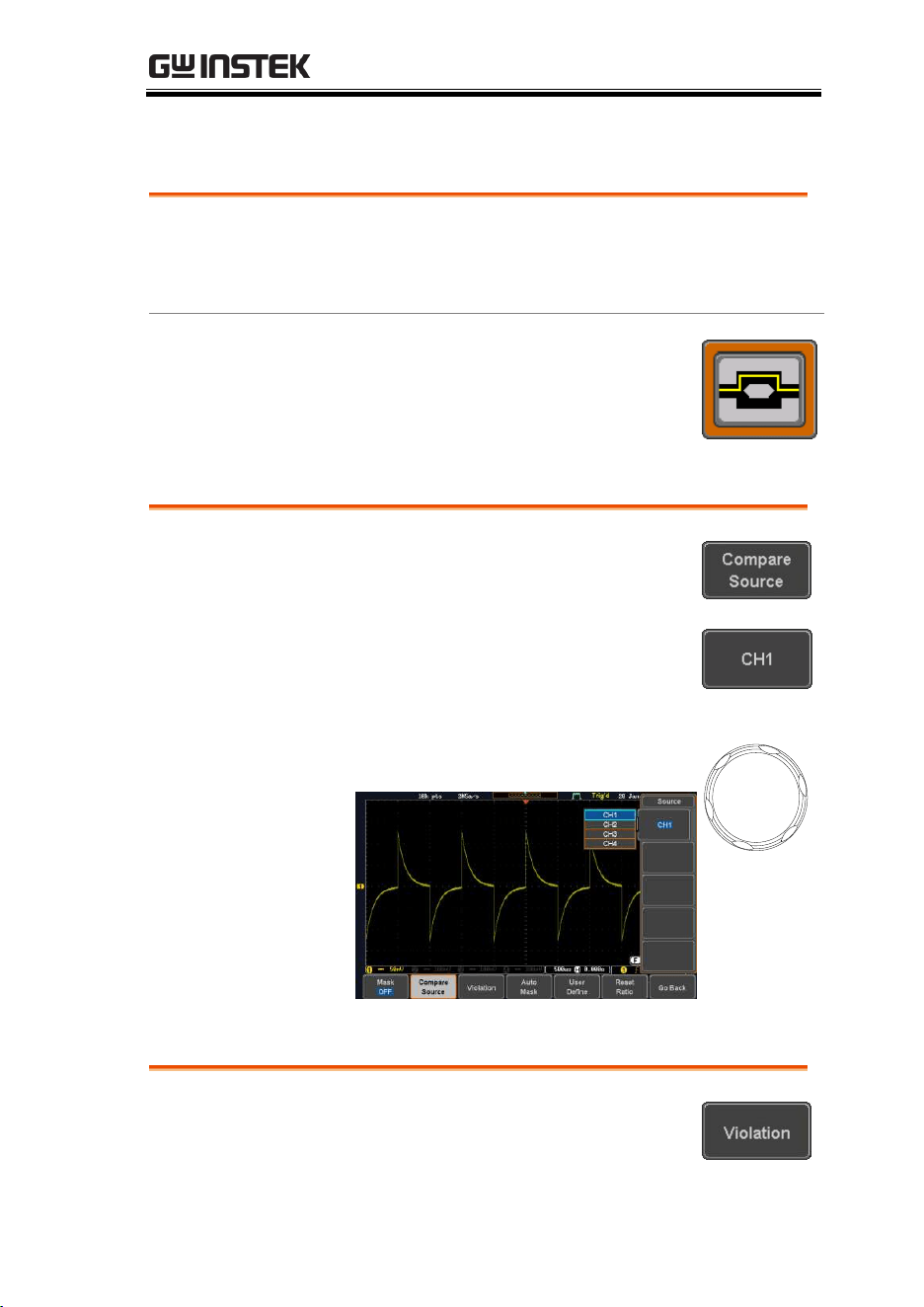
APPLICATIONS
293
Mask application
Background
The Mask application allows the user to create
shape templates for easy comparison of an input
signal with a defined shape.
Panel Operation
Choose the Mask application from the
APP menu. See page 281.
Select the source channel
Step
1. Press the Compare Source button
from the bottom menu.
2. Press the CH1 button from the
side menu and use the Variable
knob to select a source channel
(CH1, CH2 for 2 channels models
and CH1~CH4 for 4 channels
models) as a compare source.
VARIABLE
Configure the mask violation
Step
1. Press the Violation button from the
bottom menu.
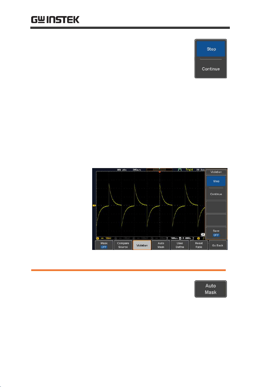
MDO-2000E series User Manual
294
2. Press the Stop button to stop the
data acquisition and freeze the
screen when the source waveform
crosses the mask boundary (mask
violation condition). Conversely,
press the Continue button to
continue acquiring data even
when a mask violation condition is
encountered.
3. Toggle the Save button to On will save a file
each time a mask violation condition is
encountered (see above). The save mode (file
type) depends on the hardcopy save setting
(see page 335).
Auto Mask
Step
1. Press the Auto Mask button from
the bottom menu to create a mask
shaped out from an existing
waveform.
2. Press the Reference Source button from the side
menu to select the pattern the mask will be
shaped on.
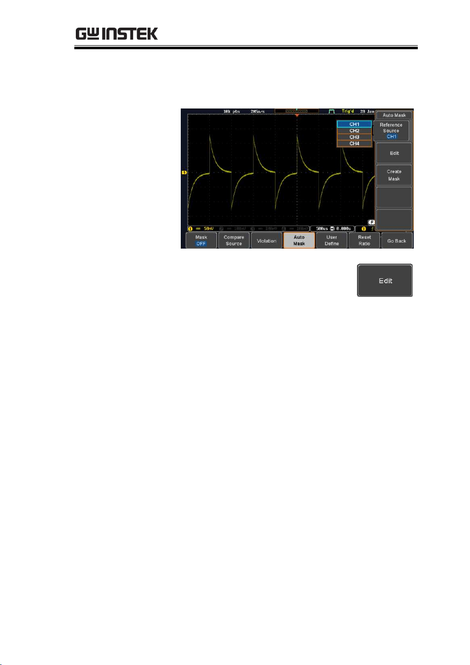
APPLICATIONS
295
3. Use the Variable knob to select the reference
source (CH1 or CH2 for 2 channels model and
CH1~CH4 for 4 channels models).
4. Press the Edit button from the side
menu if you want to further adjust
the mask pattern. Otherwise, go to
step 9 below to create the mask
directly without adjustment.
5. Press the Unit button from the side menu and
use the Variable knob to select either Divisions
(graticule division fractions) or Current (X or
Y axis actual scale units) as the units to set the
mask deviation from its original pattern.
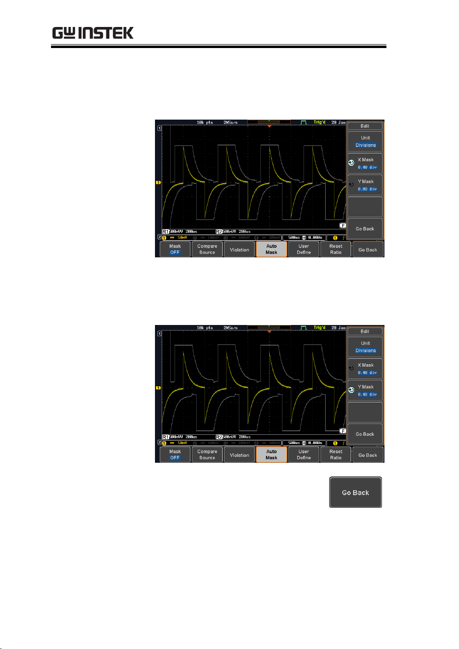
MDO-2000E series User Manual
296
6. Press the X Mask button from the side menu
and use the Variable knob to adjust the
horizontal deviation of the mask compared to
its original pattern
7. Press the Y Mask button from the side menu
and use the Variable knob to adjust the vertical
deviation of the mask compared to its original
pattern.
8. Press the Go Back button from the
side menu.
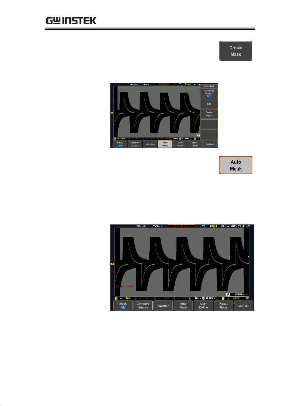
APPLICATIONS
297
9. Press the Create Mask button from
the side menu.
A mask is created (as shown in the
below diagram) and can now be
used.
10. Press the Auto Mask button from
the bottom menu to close auto
mask function.
11. Press the Mask ON button from the bottom
menu to execute the mask function and start
comparing the source channel (set in the
compare source menu) with the mask.
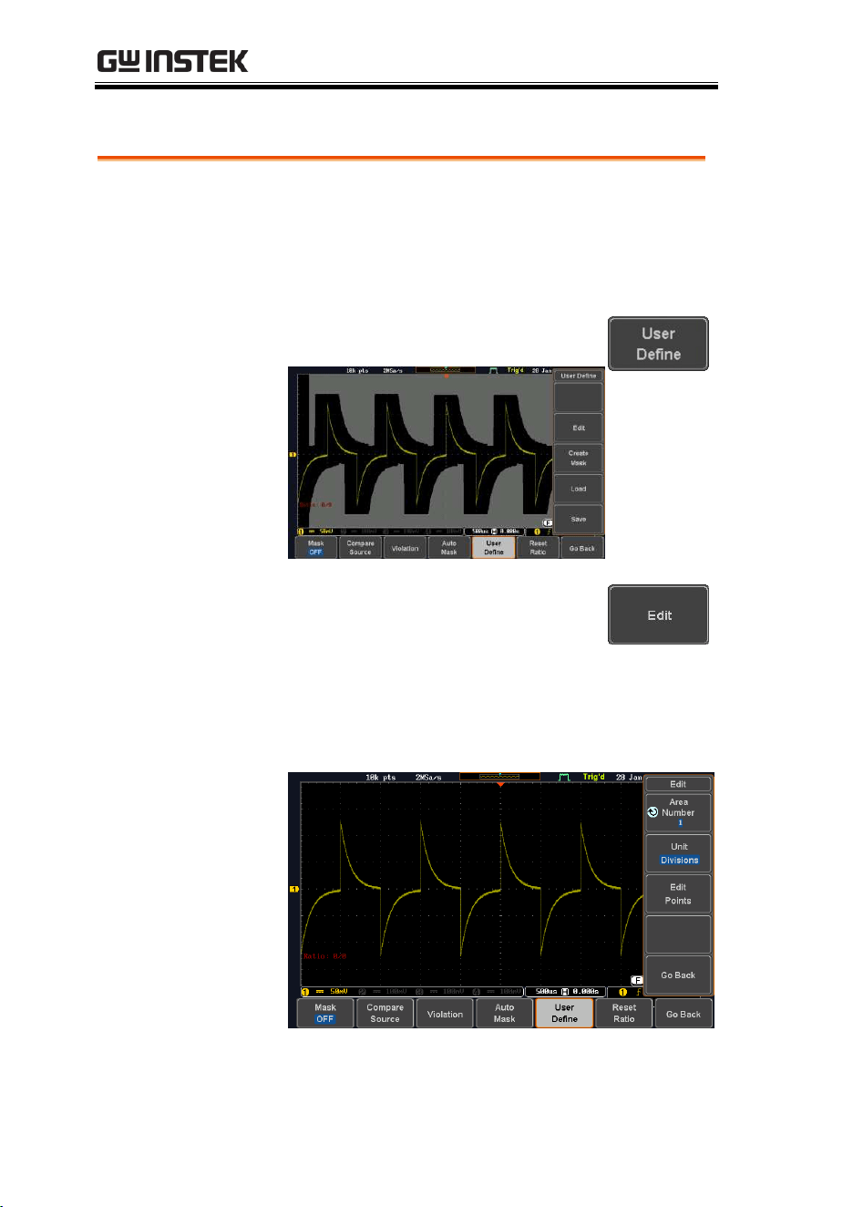
MDO-2000E series User Manual
298
User Defined Mask / Create Mask
Background
A user-defined mask can be created. Up to 8 areas
of any form, each made of up to 10 points, can be
built out and juxtaposed to each other to form the
user-defined mask pattern.
Step
1. Press the User Define button from
the bottom menu.
2. Press the Edit button from the side
menu.
Create an area
3. Press the Area Number button from the side
menu and use the Variable knob to select 1 out
of 8 areas that can be created to build the mask
pattern and start to shape it.
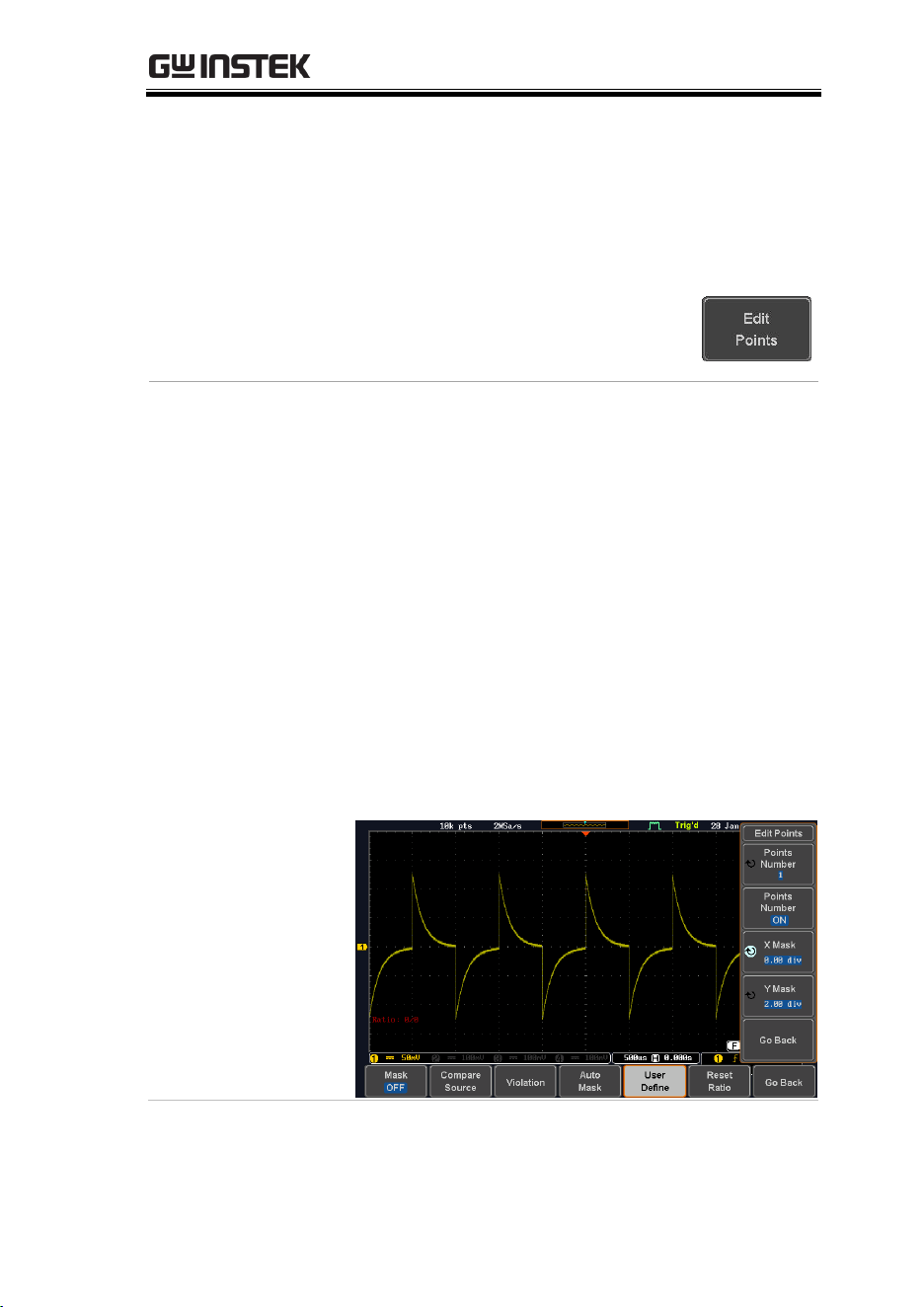
APPLICATIONS
299
4. Press the Unit button from the side menu and
use the Variable knob to either select Divisions
(graticule division fractions) or Current
(Actual oscilloscope X- and Y-axis scale units)
as the points position units.
5. Press the Edit Points button from
the side menu to start shaping the
pattern of the area you selected.
Edit the first point
6. Press the Points Number button from the side
menu and use the Variable knob to select the
first point that will shape the area pattern. Up
to 10 points can form an area pattern.
7. Press the Points Number ON button from the
side menu to activate the point.
8. Press the Y Mask button from the side menu
and use the Variable knob to adjust the vertical
position of the point (Y-axis).
9. Press the X Mask button from the side menu
and use the Variable knob to adjust the
horizontal position of the point (X-axis).
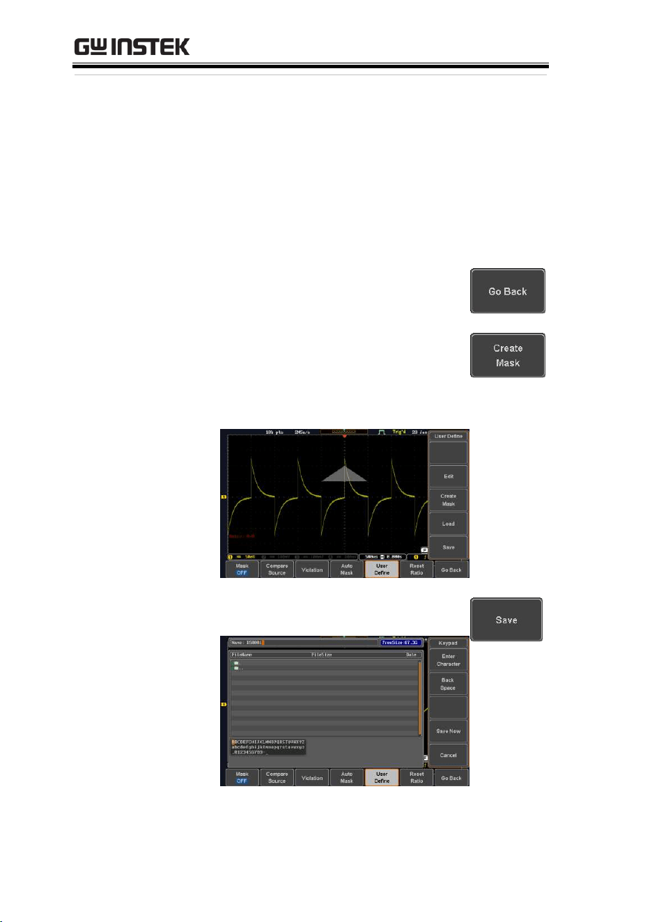
MDO-2000E series User Manual
300
Edit the other
points
10. Repeat the above steps 6 to 9 to add other
points to the area and until you finalize the
shape of this first area. Then press the Go Back
button to exit the Edit Points menu.
Create other areas
11. Repeat the above steps for as many
areas as you need to create your
mask pattern.
12. Press the Go Back button again from
the side menu.
13. Press the Create Mask button from
the side menu.
A user-defined mask is created (as
shown in the below diagram) and
can now be used.
Save the user-
defined mask
14. Press the Save button from the side
menu.
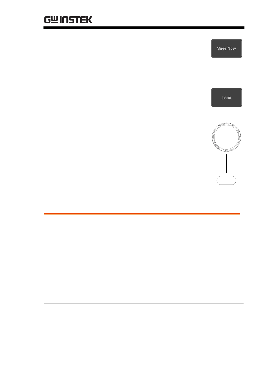
APPLICATIONS
301
15. Use the variable knob and the
select key to change the name of
the file if needed and press the Save
Now button from the side menu to
save the user-defined mask.
Load a user-
defined mask
16. From the User Define menu, you
can also load an existing mask.
Press the Load button from the side
menu, use the Variable knob to
select the file, and press the Select
key twice to load the mask.
Select
VARIABLE
User-defined Mask File Format
Background
The user-defined mask files can be created out of
support (from an external computer for example)
and uploaded to the MDO-2000E Mask
application with a USB flash disk.
Create an unformatted text file respecting the
format described below.
File extension
File_name.MSK

MDO-2000E series User Manual
302
Format
Format,2.0E,
Total Area Number,1,
Area Number,1,
Points Number,3,
0.00,2.00,
1.00,1.00,
-1.00,1.00,
Example
(with Division
units)
Format,2.0E,
Total Area Number,2,
Area Number,1,
Points Number,4,
0.00,2.00,
1.00,1.00,
0.00,0.00,
-1.00,1.00,
Area Number,2,
Points Number,3,
0.00,-2.00,
1.00,-1.00,
-1.00,-1.00,

SAVE/RECALL
303
SAVE/RECALL
File Format/Utility ....................................................304
Image File Format ................................................................................ 304
Waveform File Format ........................................................................ 304
Spreadsheet File Format...................................................................... 305
Setup File Format ................................................................................. 307
Create/Edit Labels ....................................................310
Save ..........................................................................313
File Type/Source/Destination ........................................................... 313
Save Image ............................................................................................. 314
Save Waveform ..................................................................................... 316
Save Setup .............................................................................................. 318
Recall ........................................................................321
File Type/Source/Destination ........................................................... 321
Recall Default Panel Setting ............................................................... 321
Recall Waveform .................................................................................. 324
Recall Setup ........................................................................................... 325
Reference Waveforms ................................................327
Recall and Display Reference Waveforms ....................................... 327

MDO-2000E series User Manual
304
File Format/Utility
Image File Format
Format
*.bmp or *.png
Default Filename
DSxxxx.bmp/png
Contents
The display image is 800 by 480 pixels. The
background color can be inverted (Ink saver
function). Each image file is saved to the current
file path as a bitmap or PNG file.
Waveform File Format
Format
DSxxxx.lsf, CH1~CH4.lsf
The LSF file format efficiently stores waveforms.
This is the file format used for storing and recalling
all waveforms that are used with the MDO-2000E
series.
Filename
DSxxxx.lsf
Waveform Type
CH1 ~ 4
Input channel signal
REF
Reference waveform
Math
Math operation result (page 67)
Storage Location
Wave1 ~
Wave20
Waveform files stored to the internal
memory. Stored waveforms can be
transferred to Ref. 1 ~ 4 to be viewed
on the display. (W1 ~ W20 waveforms
cannot be directly recalled on the
display).

SAVE/RECALL
305
Ref 1~4
Reference waveforms stored in the
internal memory, separate from W1 ~
W20. Reference waveforms (Ref 1 ~ 4)
can be displayed directly onto the
display with amplitude and frequency
information. Ref 1~4 are useful for
reference purposes. Other waveforms
(LSF and W1~20) must be recalled to
R1~4 before being displayed.
Contents:
Waveform Data
The waveform data can be used for detailed
analysis. It consists of the horizontal and vertical
data used by the waveform.
Spreadsheet File Format
Format
*.csv (Comma-separated values format, can be
opened in spreadsheet applications such as
Microsoft Excel).
CSV-formatted files can be stored in either a short-
memory format or a long-memory format: Detail
CSV, Fast CSV. The number of points that are
saved depends on the record length settings.
Detail CSV will record both the horizontal and
vertical sample points of the waveform. All the
points are recorded in scientific notation for analog
data.
Fast CSV will only record the vertical amplitude of
the sample points. Fast CSV also contains data that
enables the horizontal data points to be
reconstructed, such as trigger position, etc. Data is
recorded as integers.
Note, however, that only fast CSV can be recalled
to the internal memory. Detailed CSV cannot be
recalled.
Filename
DSxxxx.csv

MDO-2000E series User Manual
306
Waveform Type
CH1 ~ 4
Input channel signal
Ref1~4
Reference waveform
Math
Math operation result (page 67)
All
Displayed
All the waveforms on the display.
Contents:
Fast CSV
The following information is included in the Fast
CSV waveform files, where applicable:
Format
(scope type)
Memory length
IntpDistance
(input trigger distance)
Trigger address
Trigger level
Source
Vertical units
Vertical units div
Vertical units extend
div
Label
Probe type
Probe ratio
Vertical scale
Vertical position
Horizontal units
Horizontal scale
Horizontal position
Horizontal mode
SincET mode
(sampling mode)
Sampling period
Horizontal old scale
Horizontal old
position
Firmware
Time
Mode
Raw vertical
waveform data

SAVE/RECALL
307
Contents:
Detail CSV
Detail CSV waveform data contains channel
information such as vertical and horizontal
position of a signal for all the recorded points.
The following information is included in Detail
CSV, where applicable:
Format
(scope type)
Memory length
IntpDistance
(input trigger distance)
Trigger address
Trigger level
Source
Vertical units
Vertical units div
Vertical units extend
div
Label
Probe type
Probe ratio
Vertical scale
Vertical position
Horizontal units
Horizontal scale
Horizontal position
Horizontal mode
SincET mode
(sampling mode)
Sampling period
Horizontal old scale
Horizontal old
position
Firmware
Time
Mode
Raw vertical
waveform data
Horizontal data
Vertical data
Setup File Format
Format
DSxxxx.set (proprietary format)
The setup file saves or recalls the following
settings.

MDO-2000E series User Manual
308
Contents
Acquire
Mode
Sample rate
XY
Sample mode
Record Length
Display
Mode
Persistence
Waveform
intensity
Graticule
intensity
Backlight
intensity
Graticule
Backlight
Auto-dim
Channel
Scale
Channel
Coupling
Impedance
Invert
Bandwidth
Expand
Position
Probe
Probe
attenuation
Deskew
Cursor
Horizontal
cursor
H Unit
Vertical cursor
V Unit
Measure
Source
Gating
Statistics
Display
High-Low
Reference levels
Horizontal
Scale
Math
Source1
Operator
Source2
Position
Unit/Div
Math Off
FFT Math
Source
Vertical Units
Window
Vertical position
Horizontal
position

SAVE/RECALL
309
Advanced
Math
Expression
VAR1
VAR2
Position
Unit/Div
Trigger
Type
Source
Coupling
Alternate
Rejection
Noise Rejection
Slope
Level
Mode
Trigger When
Timer
Holdoff
Utility
Language
Hardcopy key
File Format
Ink Saver
Assign Save
Probe Comp.
Save/
recall
Image file
format
Data file format
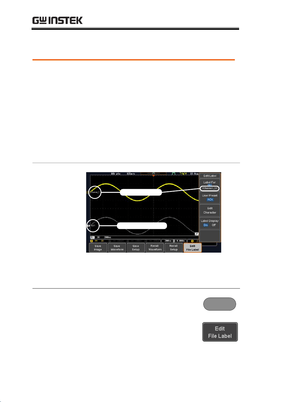
MDO-2000E series User Manual
310
Create/Edit Labels
Overview
Reference files, Setup files and the analog and
digital input channels can have individual file
labels set.
For the analog channels and reference waveforms,
the file label can be displayed next to the
channel/reference indicator.
The file labels are also used to easily identify
reference files, setup files or channels when saving
or recalling waveforms and setups.
Example
Label for CH1
Label for Ref 1
In the example above, the file label for channel 1 is
displayed next to the channel indicator and is also
displayed in the Edit Label menu. The Ref_1 file
label is shown next to the reference indicator.
Panel Operation
1. Press the Save/Recall key from the
front panel.
Save/Recall
2. Press Edit File Label from the
bottom menu.
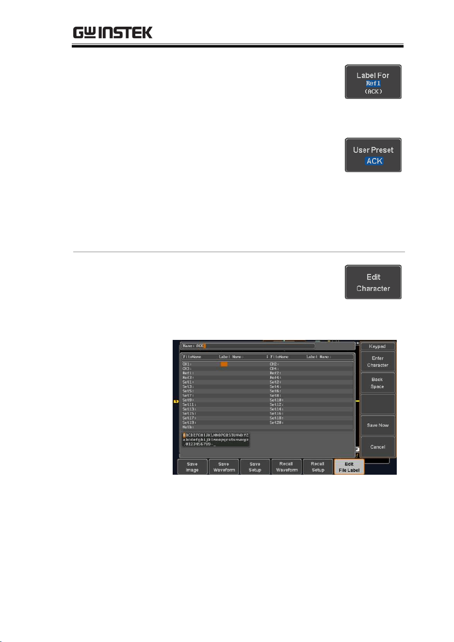
SAVE/RECALL
311
3. Press Label For and select the item
that you want to create the label
for.
Label For
CH1~CH4, Ref1~4, Set1~20, Math
4. To choose a preset label, Press User
Preset from the side menu and
choose a label.
Labels
ACK, AD0, ANALOG, BIT, CAS,
CLK, CLOCK, CLR, COUNT,
DATA, DTACK, ENABLE, HALT,
INT, IN, IRQ, LATCH, LOAD,
NMI
Edit Label
5. Press Edit Character to edit the
current label.
6. The Edit Label window appears.
7. Use the Variable knob to highlight
a character.
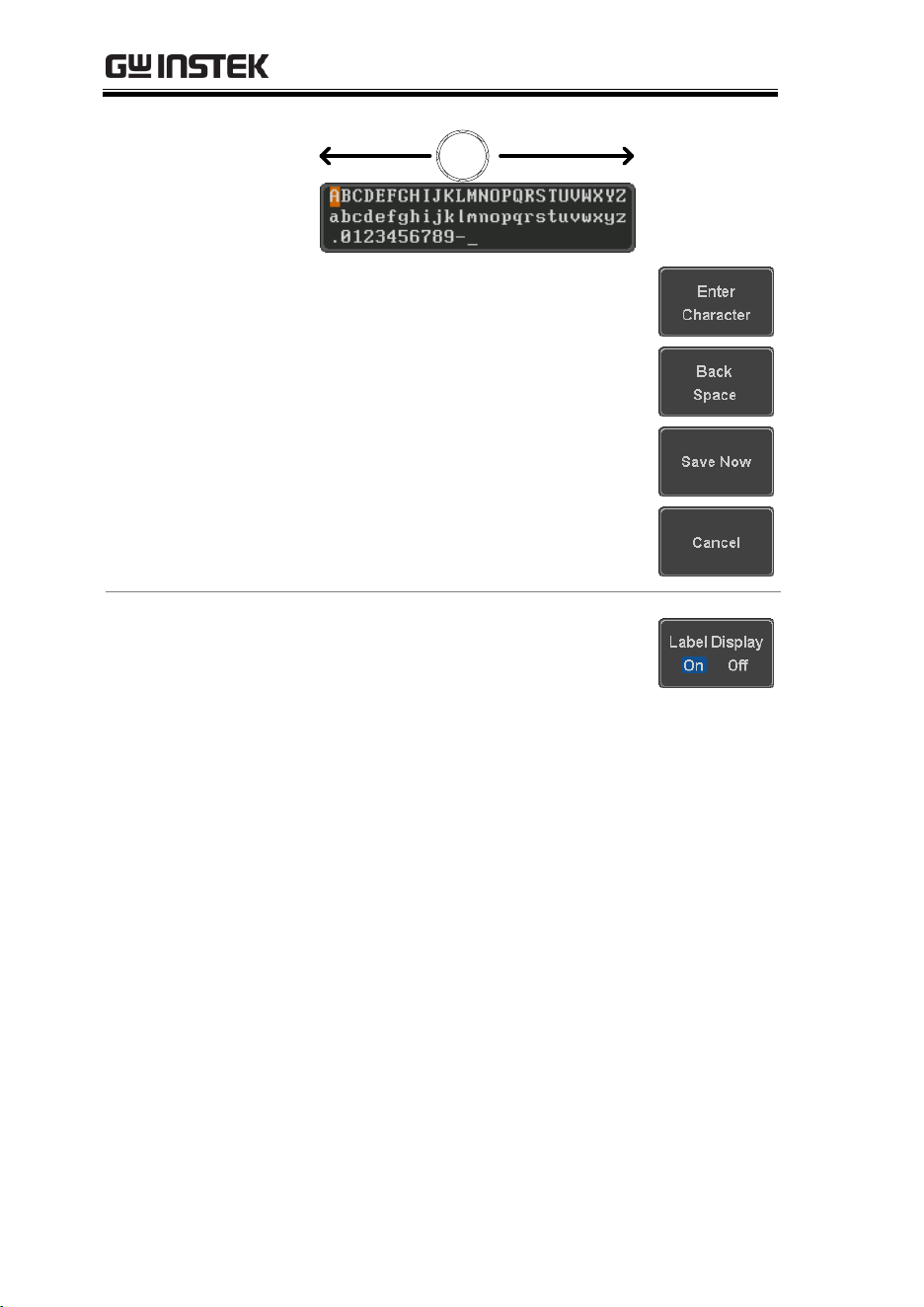
MDO-2000E series User Manual
312
VARIABLE
Press Enter Character to select a
number or letter.
Press Back Space to delete a
character.
Press Save Now to save the label
and return to the previous menu.
To cancel the editing the label and
return to the previous menu, press
Cancel.
Display Label
To display the currently selected
file label on the screen next to its
respective indicator, toggle Label
Display to On.
Conversely, if you want to remove
the currently selected file label
from the display, toggle Label
Display to Off.

SAVE/RECALL
313
Save
File Type/Source/Destination
Item
Source
Destination
Panel Setup
(DSxxxx.set)
Front panel
settings
Internal memory: Set1 ~
Set20
File system: Disk, USB
Waveform Data
(DSxxxx.csv)
(DSxxxx.lsf)
(CH1~CH4.lsf,
Ref1~Ref4.lsf,
Math.lsf)*
ALLxxxx.csv
Channel 1 ~ 4
Math operation
result
Reference
waveform Ref1~4
All displayed
waveforms
Internal memory:
Reference waveform
Ref1~4, Wave1 ~ Wave20
File system: Disk, USB
Display Image
(DSxxxx.bmp/png)
(Axxx1.bmp/png)**
Display image
File system: Disk, USB
*Stored in ALLXXXX directories when All Displayed waveforms are
saved.
**Stored in ALLXXXX directories when the Hardcopy key is
assigned to save Waveform, Setup or All.
Note: By default all filenames/directories are named
DSxxxx/ALLxxxx where xxxx is a number starting from 0001 and is
incremented by one after each save.
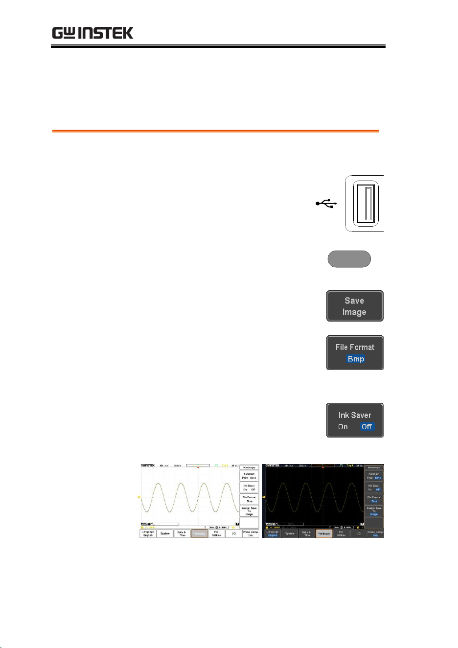
MDO-2000E series User Manual
314
Save Image
Images can be saved either using the Save/Recall key or by using
the Hardcopy key. To save images using the Hardcopy key, see the
hardcopy section on page 335.
Panel Operation
1. To save to USB, connect a USB
drive to the front panel USB
port. If a USB drive is not
connected, images can still be
saved to the internal memory.
Front Panel
2V
2. Press the Save/Recall key from the
front panel.
Save/Recall
3. Press Save Image from the bottom
menu.
4. Press File Format to choose PNG or
BMP file types.
Range
DSxxxx.bmp, DSxxxx.png
5. Press Ink Saver to toggle Ink Saver
On or Off.
Ink Saver On
Ink Saver Off
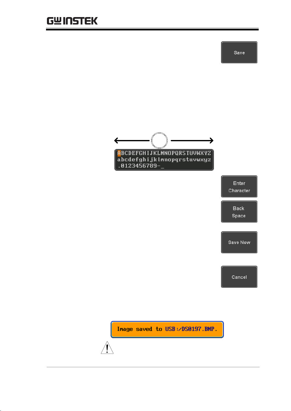
SAVE/RECALL
315
6. Press Save from the side menu to
save the display as an image file.
7. You will automatically be taken to a file utility
where you will be able to edit the name of the
file.
8. To edit the file name, use the Variable knob to
highlight a character.
VARIABLE
Press Enter Character or the Select
key to select a number or letter.
Press Back Space to delete a
character.
9. Press Save Now to save the file. The
file name need not have been
edited to save the file.
Note: Pressing Cancel will cancel
the save operation and return you
to the Save/Recall menu.
After Save Now has been pressed the file will be
saved.
Note
The file will not be saved if the power
is turned off or the USB drive is taken
out before the message ends.
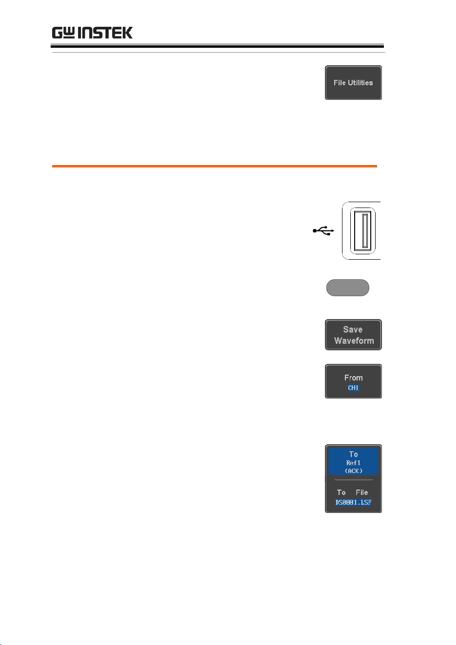
MDO-2000E series User Manual
316
File Utility
To edit the internal memory or the
USB flash drive contents (create/
delete/rename files and folders) or to
edit the default file path, press File
Utilities from the side menu.
Save Waveform
Panel Operation
1. To save to an external USB flash
drive, connect the drive to the
front panel USB port. If a USB
drive is not connected, files can
still be saved to the internal
memory.
Front Panel
2V
2. Press the Save/Recall key from the
front panel.
Save/Recall
3. Press Save Waveform from the
bottom menu.
4. Choose the From waveform on the
side menu.
Source
CH1~4, Math, Ref1~4, All
Displayed
5. Press To (internal memory) or To
File and choose a destination to
save.
To
Ref1~4, Wave1~20
To File
Format: LSF, Detail CSV, Fast CSV
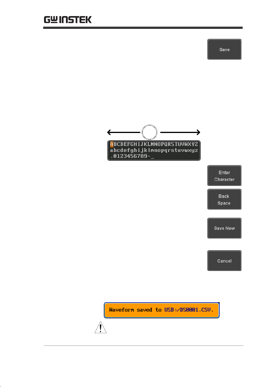
SAVE/RECALL
317
6. Press Save to save the file.
7. If you are saving to a file, a file utility appears
where you will be able to edit the name of the
file from the default “DSXXX” filename.
8. To edit the filename, use the Variable knob to
highlight a character.
VARIABLE
Press Enter Character or the Select
key to select a number or letter.
Press Back Space to delete a
character.
9. Press Save Now to save the file. The
filename need not have been
edited to save the file.
Note: Pressing Cancel will cancel
the save operation and return you
to the Save/Recall menu.
After Save Now has been pressed the file will be
saved.
Note
The file will not be saved if the power
is turned off or the USB drive is taken
out before the message ends.
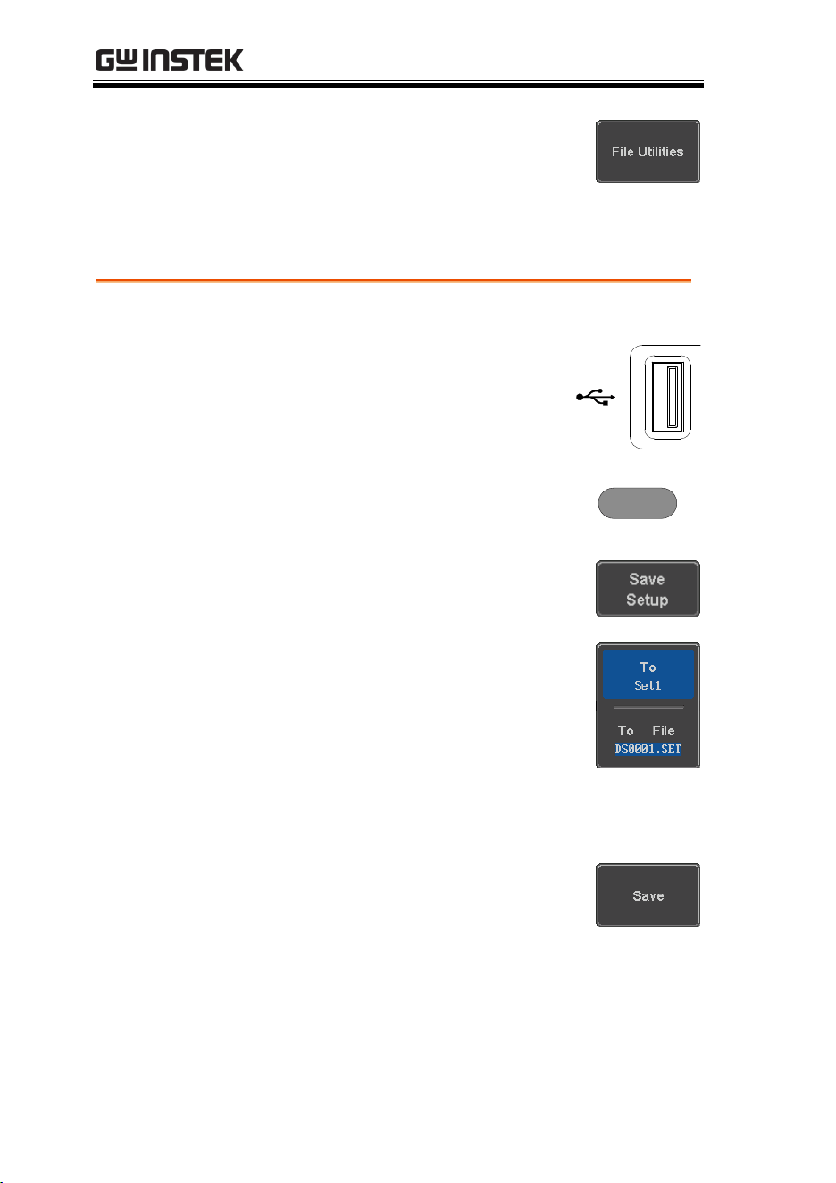
MDO-2000E series User Manual
318
File Utility
To edit the internal memory or the
USB flash drive contents (create/
delete/rename files and folders), press
File Utilities.
Save Setup
Panel Operation
1. To saving to an external USB
flash drive connect the drive to
the front or rear panel USB port.
If a USB drive is not connected,
files can be saved to the internal
memory.
Front Panel
2V
2. Press the Save/Recall key from the
front panel.
Save/Recall
3. Press Save Setup from the bottom
menu.
4. Press To (internal memory) or To
File and choose a destination to
save to.
To
Set1~Set20
To File
DSxxxx.set
5. Press Save to confirm saving. When
completed, a message appears at
the bottom of the display.
6. If you are saving to a file, a file utility appears
where you will be able to edit the name of the
file from the default “DSxxxx” filename.
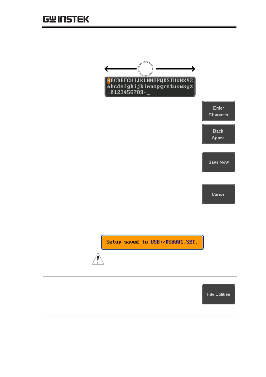
SAVE/RECALL
319
7. To edit the filename, use the Variable knob to
highlight a character.
VARIABLE
Press Enter Character or the Select
key to select a number or letter.
Press Back Space to delete a
character.
8. Press Save Now to save the file. The
filename need not have been
edited to save the file.
Note: Pressing Cancel will cancel
the save operation and return you
to the Save/Recall menu.
After Save Now has been pressed the file will be
saved.
Note
The file will not be saved if the power
is turned off or the USB drive is taken
out before the message ends.
File Utility
To edit the internal memory or the
USB flash drive contents (create/
delete/ rename files and folders) or to
set the file path, press File Utilities.


SAVE/RECALL
321
Recall
File Type/Source/Destination
Item
Source
Destination
Default Panel
Setup
Factory installed
setting
Current front panel
Reference
Waveform
Internal memory:
Ref1~4
Current front panel
Panel Setup
(DSxxxx.set)
Internal memory: S1 ~
S20
File system: Disk, USB
Current front panel
Waveform Data
(DSxxxx.lsf,
DSxxxx.csv**)
(CH1~CH4.lsf,
Ref1~Ref4.lsf,
Math.lsf)*
Internal memory:
Wave 1 ~ Wave20
File system: Disk, USB
Reference waveform
1 ~ 4
*Recalled from ALLXXX directories. Note that Allxxxx.csv cannot be
recalled to the oscilloscope.
**Detail CSV files cannot be recalled to the oscilloscope.
Recall Default Panel Setting
Panel Operation
1. Press the Default key.
Default
2. The screen will update with the default panel
settings.
Setting Contents
The following is the default (factory) setting
contents.

MDO-2000E series User Manual
322
Acquire
Mode: Sample
XY: OFF
Record Length: 10k
Expand: By Center
Display
Mode: Vector
Persistence: 240ms
Waveform intensity: 50%
Graticule intensity: 50%
Backlight Intensity: 80%
Backlight Auto-dim: On
Time: 10min
Graticule: full
Channel
Scale: 100mV/Div
CH1: On
Coupling: DC
Impedance: 1MΩ
Invert: Off
Bandwidth: full
Expand: By Ground
Position: 0.00V
Probe: Voltage
Probe attenuation: 1x
Deskew: 0s
Cursor
Horizontal cursor: Off
Vertical Cursor: Off
Measure
Source: CH1
Gating: Screen
Display All: Off
High-Low: Auto
Statistics: Off
Mean & Std Dev
Samples: 2
High Ref: 90.0%
Mid Ref: 50.0%
Low Ref: 10.0%
Horizontal
Scale: 10us/Div
Position: 0.000s
Math
Source1: CH1
Operator: +
Source2: CH2
Position: 0.00 Div
Unit/Div: 200mV
Math Off
FFT
Source: CH1
Vertical Units: dBV RMS
Window: Hanning
Vertical: 20dB
Horizontal:5MHz/div
Advanced Math
Expression: CH1+CH2
VAR1: 0
VAR2: 1
Position: 0.00Div

SAVE/RECALL
323
Unit/div: 500mV
APP
App: Go-NoGo, DVM, Datalog, Mount Remote
Disk
Trigger
Type: Edge
Source: CH1
Coupling: DC
Alternate: Off
Noise Rejection: Off
Slope: Positive
Level: 0.00V
Mode: Auto
Holdoff: 10.0ns
Utility
Hardcopy: Save
Ink Saver: Off
Assign Save To: Image
File Format: Bmp
Probe Comp.: 1kHz
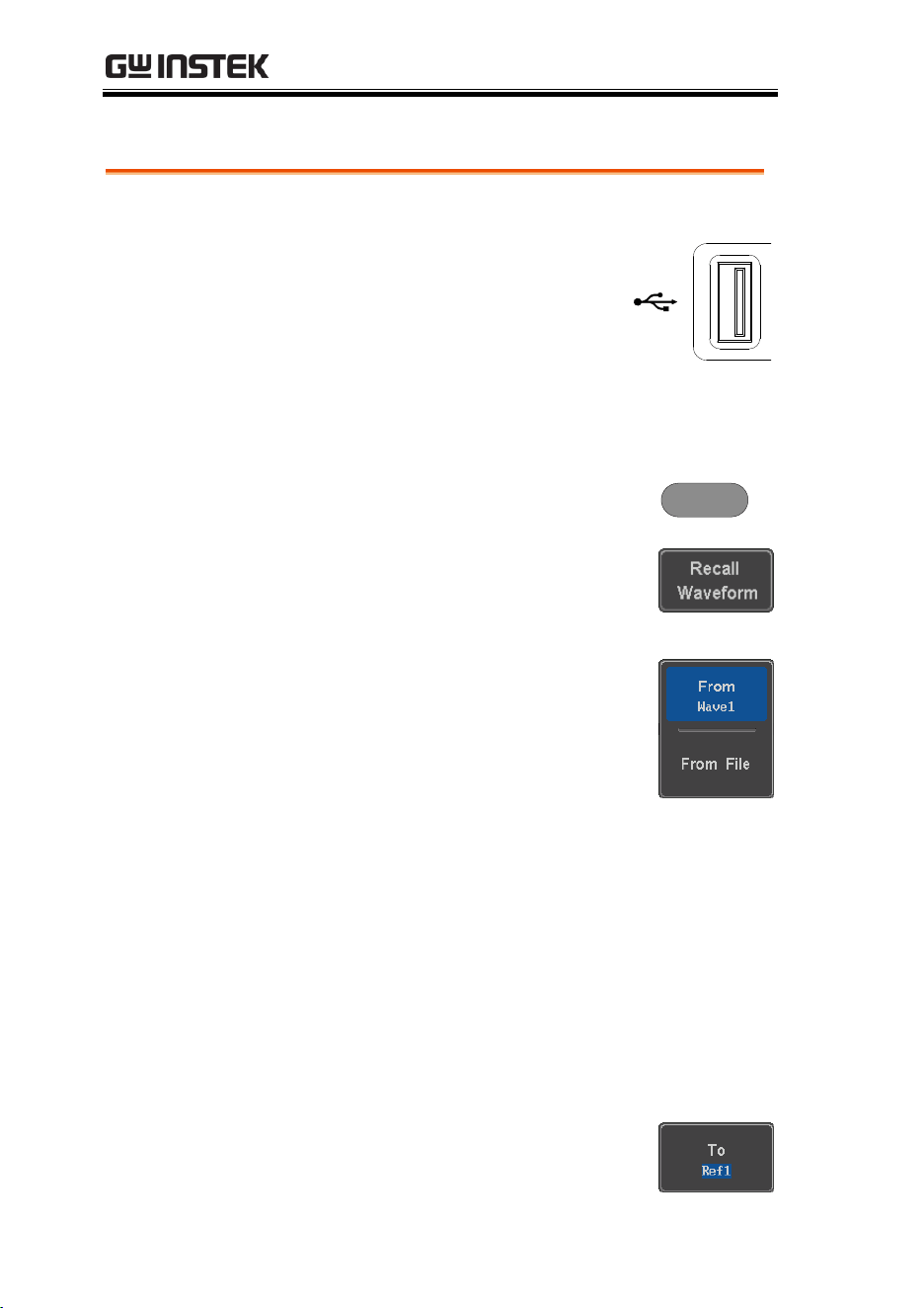
MDO-2000E series User Manual
324
Recall Waveform
Panel Operation
1. For recalling from an external
USB flash drive, connect the
drive to the front or rear panel
USB port.
Front Panel
2V
2. The waveform must be stored in advance. See
page 316 for waveform store details.
3. Press the Save/Recall key.
Save/Recall
4. Press Recall Waveform from the
bottom menu. The Recall menu
appears.
5. Press From (internal memory) or
From File and choose a source to
recall from.
From
Wave1~20
From File*
File format: Lsf, Fast Csv
*Only files in the current file path will be
available, this includes files saved in the
ALLxxxx directories.
Allxxxx.csv files cannot be recalled to the
oscilloscope.
Only the “Fast CSV”, “LSF” files can be recalled
to the oscilloscope.
6. Press To and select the reference
waveform to recall to.
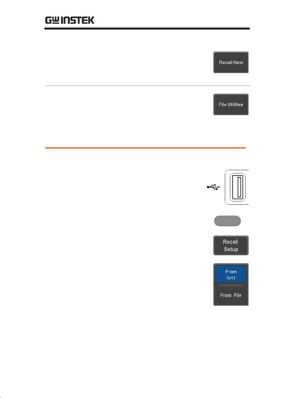
SAVE/RECALL
325
To
Ref1~4
7. Press Recall Now to recall the
waveform. The reference
waveform will appear on the
screen when successful.
File Utility
To edit USB flash drive contents
(create/ delete/ rename files and
folders) or to set the file path, press
File Utilities.
Recall Setup
Panel Operation
1. (For recalling from an external
USB flash drive) Connect the
drive to the front or rear panel
USB port.
Front Panel
2V
2. Press the Save/Recall key.
Save/Recall
3. Press Recall Setup from the bottom
menu.
4. Press From (internal memory) or
From File and choose a source to
recall from.
From
Set1~20
From File
DSxxxx.set (USB, Disk)*
* Only files in the current file path will be
available.
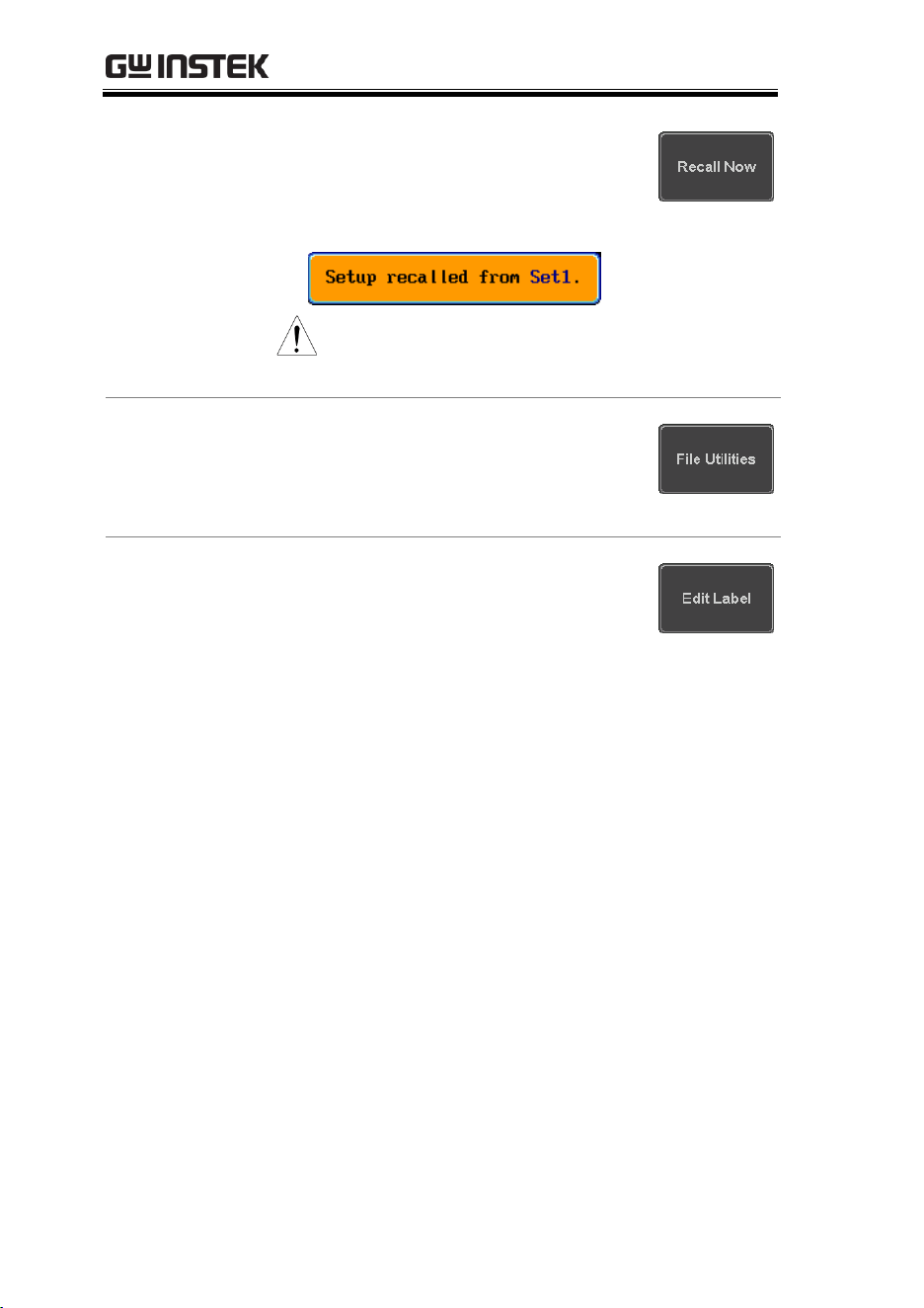
MDO-2000E series User Manual
326
5. Press Recall Now to confirm
recalling. When completed, a
message appears at the bottom of
the display.
Note
The file will not be recalled if the
power is turned off or the USB drive is
taken out before the message appears.
File Utility
To edit the internal memory or the
USB flash drive contents (create/
delete/ rename files and folders) or to
set the file path, press File Utilities.
Edit Label
To edit labels for Setup files, press Edit
label. For more details on editing
labels, see page 310.
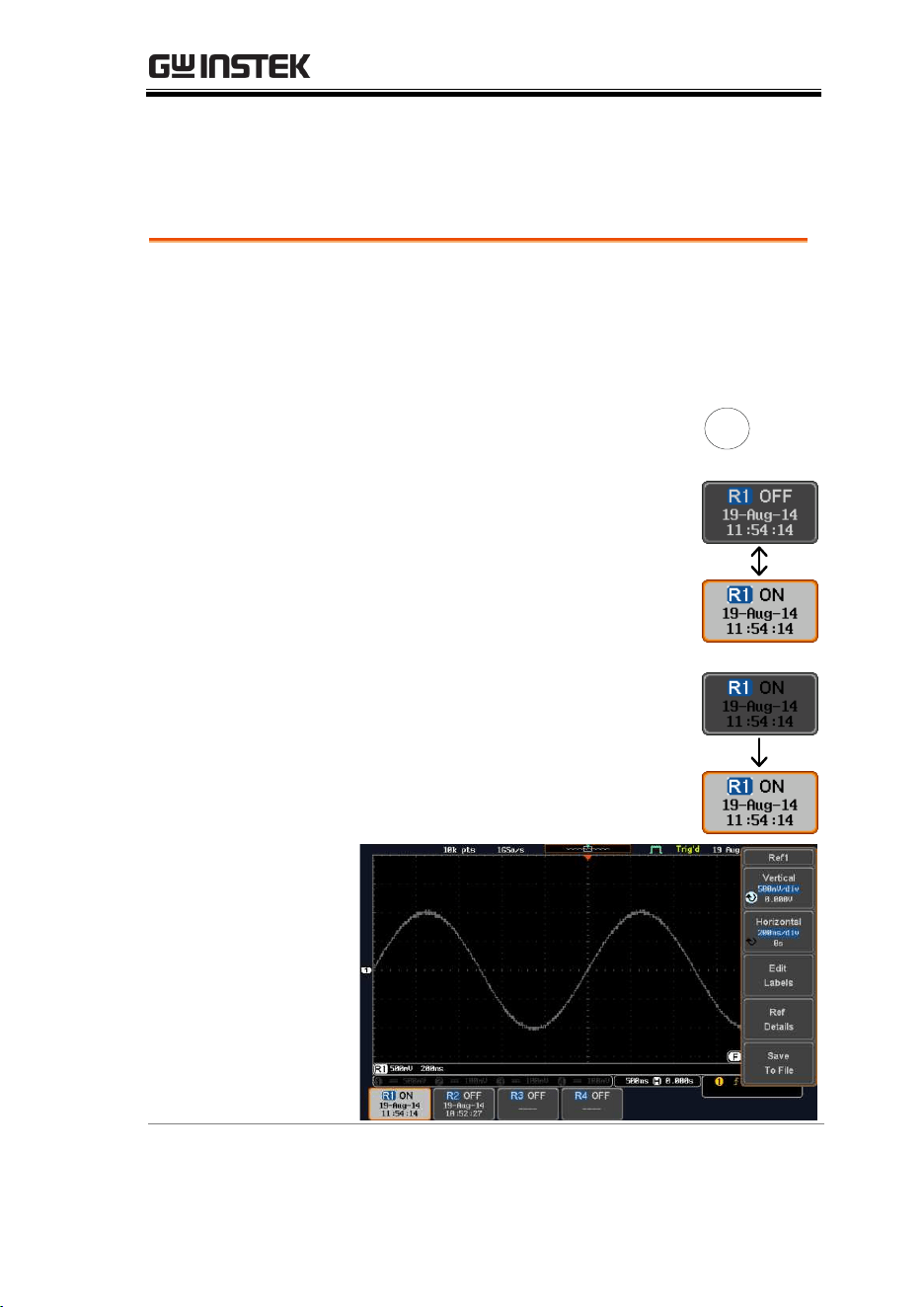
SAVE/RECALL
327
Reference Waveforms
Recall and Display Reference Waveforms
Panel Operation
A reference waveform must be stored in advance.
See page 316 to store waveforms as reference
waveforms.
1. Press the REF key on the front
panel.
REF
R
2. Pressing R1~R4 repeatedly will
toggle the corresponding reference
waveform OFF/ON.
Turning R1~R4 ON will open the
corresponding reference menu.
3. If a reference waveform is ON but
not active, its reference menu can
be opened by pressing the
corresponding R1~R4 key from the
bottom menu.
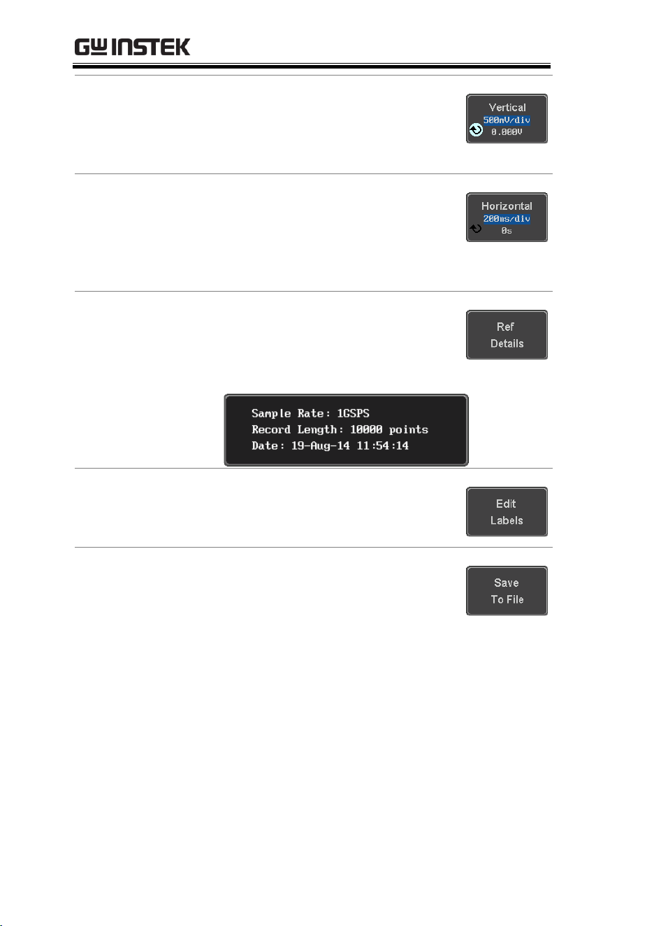
MDO-2000E series User Manual
328
Vertical
Navigation
Press Vertical repeatedly from the side
menu to choose to edit the vertical
position or Unit/Div. Use the Variable
knob to edit the values.
Horizontal
Navigation
Press Horizontal repeatedly from the
side menu to choose to edit the
Time/Div or the horizontal position.
Use the Variable knob to edit the
value.
View Reference
Waveform Details
Pressing Ref Details will display the
reference waveform details.
Details:
Sample Rate, Record Length, Date
Edit Labels
To edit labels for Setup files, press Edit
Labels. For more details on editing
labels, see page 310.
Save Reference
Waveforms
To save reference waveforms, press
Save to File. For more details on saving
waveforms, see page 316.

FILE UTILITIES
329
FILE UTILITIES
The file utilities are used each time files need to be saved to internal
or external memory. The file utilities can create, delete and rename
directories or files as well as copy files from internal memory to
USB. The File Utilities menu also sets the file path for saving and
recalling files from the Save/Recall menu.
File Navigation ...................................................................................... 330
Create Folder ......................................................................................... 331
Rename File ........................................................................................... 332
Delete File or Folder ............................................................................ 333
Copy File to USB.................................................................................. 334
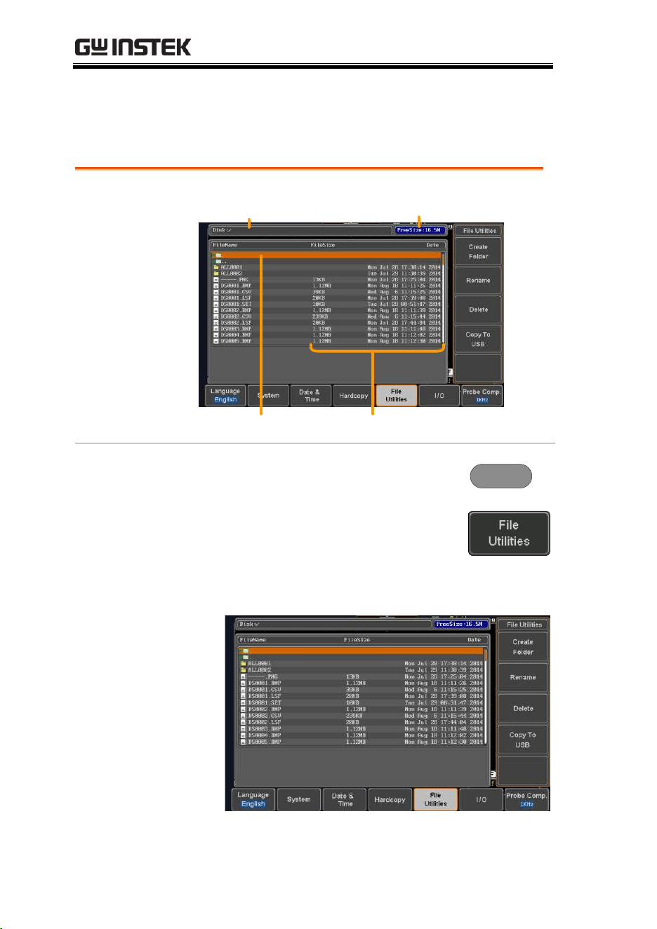
MDO-2000E series User Manual
330
File Navigation
The File Utilities menu can be used to choose files or to set the file
path for saving/recalling files.
File System
File path Drive space
File cursor File attributes
Panel Operation
1. Press the Utility key.
Utility
2. Press File Utilities from the bottom
menu.
3. The file system appears.
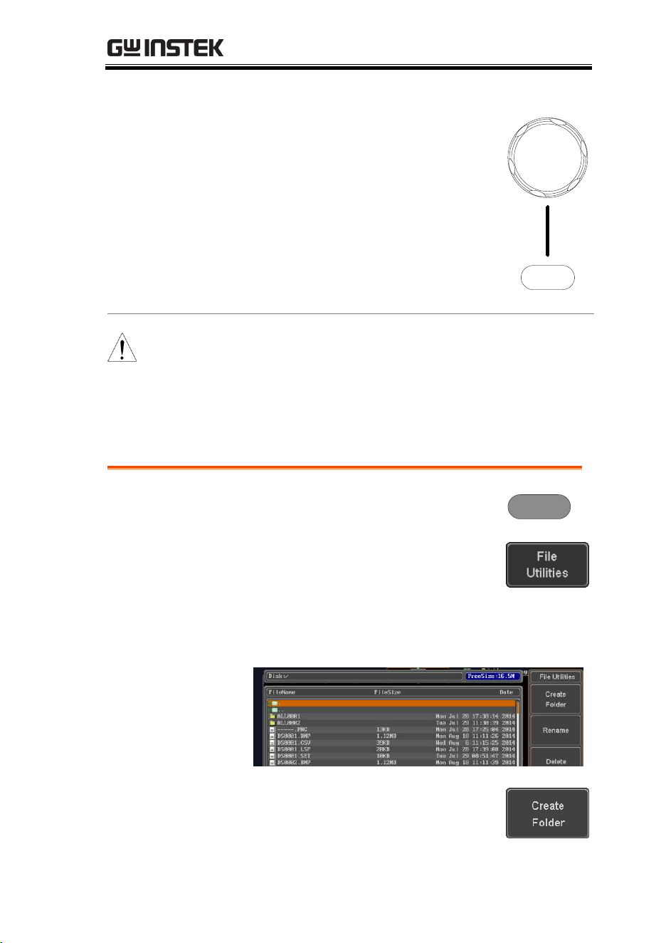
FILE UTILITIES
331
4. Use the Variable knob to move the
file cursor up and down.
Use the Select key to choose a file
or directory or to set the file path.
Select
VARIABLE
Note
When a USB flash drive is used, the file path is
remembered each time the USB flash drive is
used. This saves you the hassle of setting the
USB file path each time the USB flash drive is
inserted into the scope.
Create Folder
Panel Operation
1. Press the Utility key.
Utility
2. Press File Utilities from the bottom
menu.
3. Use the Variable knob and Select key to navigate
the file system.
Create Folder
4. Press Create Folder to make a new
directory at the selected location.
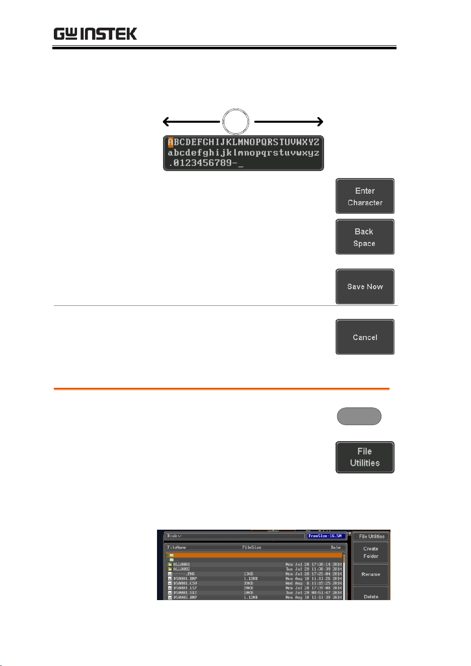
MDO-2000E series User Manual
332
5. Use the Variable knob to highlight a
character.
VARIABLE
Press Enter Character or the Select
key to select a number or letter.
Press Back Space to delete a
character.
6. Press Save Now to create the folder.
Cancel
Press Cancel to cancel the operation.
Rename File
Panel Operation
1. Press the Utility key.
Utility
2. Press File Utilities from the bottom
menu.
3. Use the Variable knob and select
key to choose a file to rename.
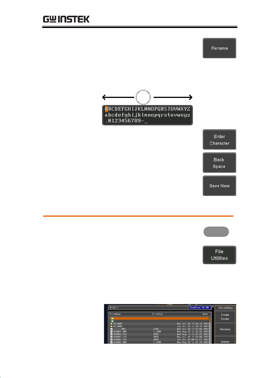
FILE UTILITIES
333
4. Press Rename when a file is chosen.
5. Use the Variable knob to highlight a
character.
VARIABLE
Press Enter Character or the Select
key to select a number or letter.
Press Back Space to delete a
character.
6. Press Save Now to rename the
folder or file.
Delete File or Folder
Panel Operation
1. Press the Utility key.
Utility
2. Press File Utilities from the bottom
menu.
3. Use the Variable knob and select
key to navigate the file system to
choose a file.

MDO-2000E series User Manual
334
4. Press Delete to delete the selected
file.
5. Press Delete again to confirm the
deletion.
Copy File to USB
Panel Operation
1. Connect a USB drive to the
front panel USB port.
Front Panel
2V
2. Press the Utility key.
Utility
3. Press File Utilities from the bottom
menu.
4. Use the Variable knob and Select key to
navigate the file system to choose a file from
internal memory.
5. Press Copy to USB to copy the
selected file to the USB drive.
Note
If the same file name already exists on the USB
drive, it will be copied over.
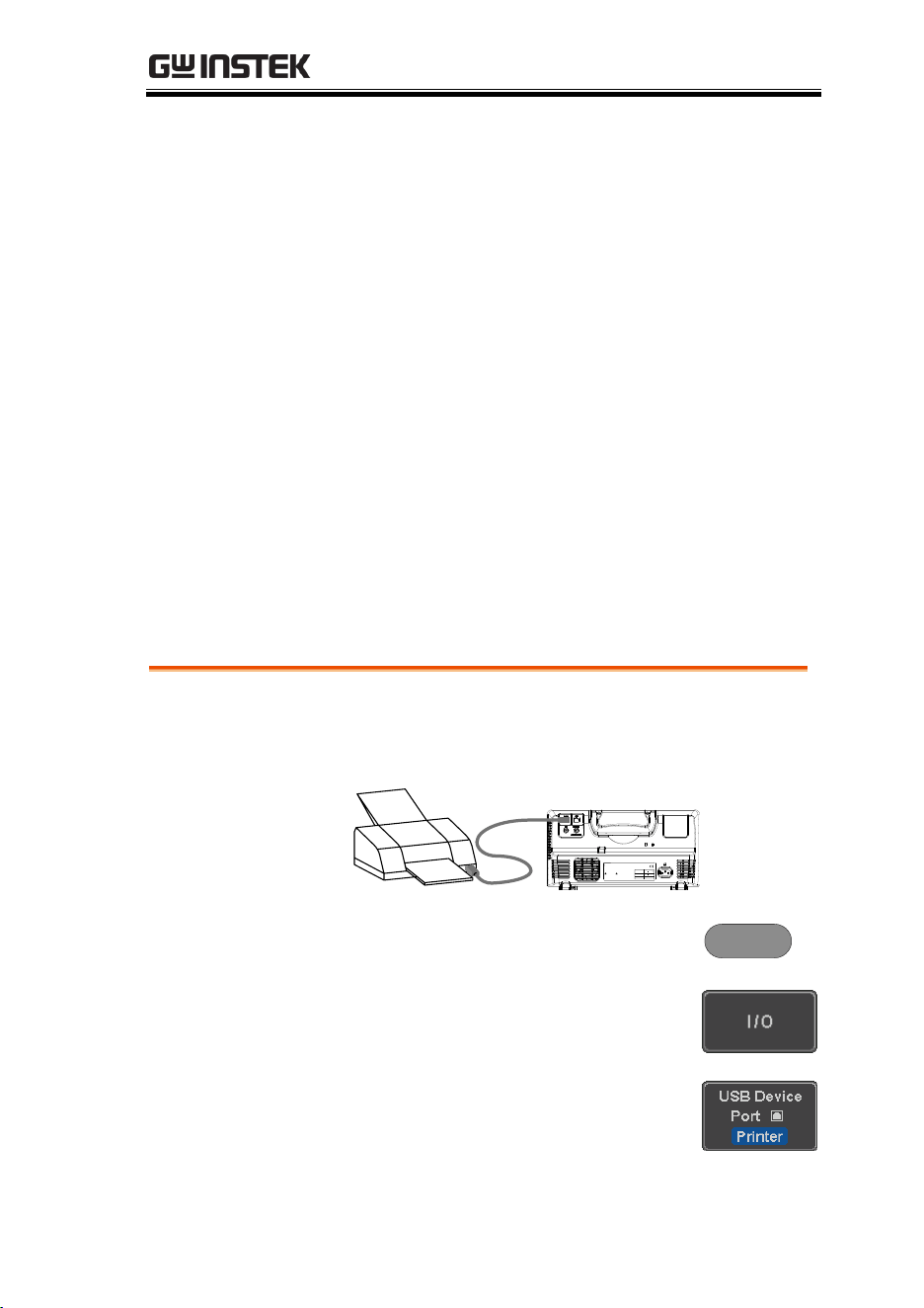
HARDCOPY KEY
335
HARDCOPY KEY
The Hardcopy key is used as quick-save or quick-print key. The
Hardcopy key can be assigned either to printout screenshots or to
save files.
When assigned to “Print” the screen image can be printed to a
PictBridge compatible printer using the USB device port. To reduce
the amount of printer ink used for each print, images can be
printed using the Ink Saver function.
When assigned to “Save”, pressing the Hardcopy key can be used
to save a screen shot, a waveform, or the current setup, depending
on the configuration.
Printer I/O Configuration
Panel Operation
1. Connect a PictBridge printer to the USB device
port on the rear panel.
LINE VOLTAGE
AC 100 240V
RANGE
FREQUENCY 50 60Hz
POWER MAX. 30 Watts
CAUTION
TO AVOID ELECTRIC SHOCK THE POWER CORD PROTECTIVE GROUNDING
DO NOT REMOVE COVERS. REFER SERVICING TO QUALIFIED PERSONNEL.
CONDUCTOR MUST BE CONNECTED TO GROUND.
Ser. No. Label
2. Press the Utility key.
Utility
3. Press I/O from the bottom menu.
4. Press USB Device Port from the side
menu and select Printer.
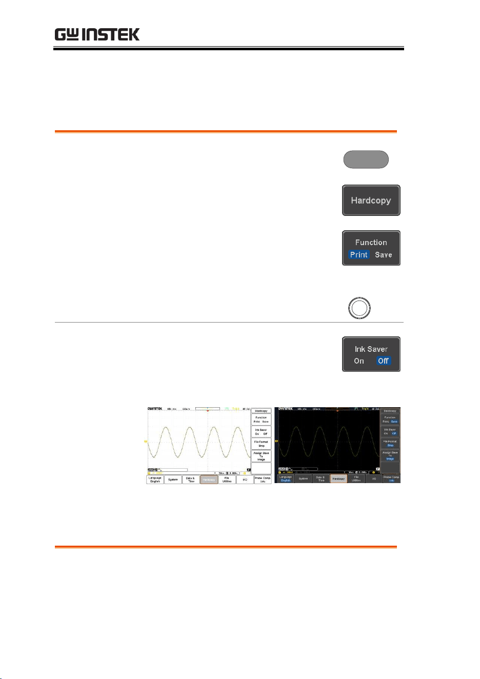
MDO-2000E series User Manual
336
Print Output
Ensure the USB port has been configured for the printer and the
printer is connected to the scope before trying to print, see page
335.
Panel Operation
1. Press the Utility key.
Utility
2. Press Hardcopy from the bottom
menu.
3. On the side menu, press Function
and select Print.
4. Press the Hardcopy key to print.
The display image is printed out.
Hardcopy
Ink Saver
To have a white background on the
printed display image, set Ink Saver to
On.
Ink Saver On
Ink Saver Off
Save - Hardcopy Key
Background
When the Hardcopy key is assigned to “Save”,
pressing the Hardcopy key can be used to save a
screen shot, a waveform, or the current setup,
depending on the configuration.
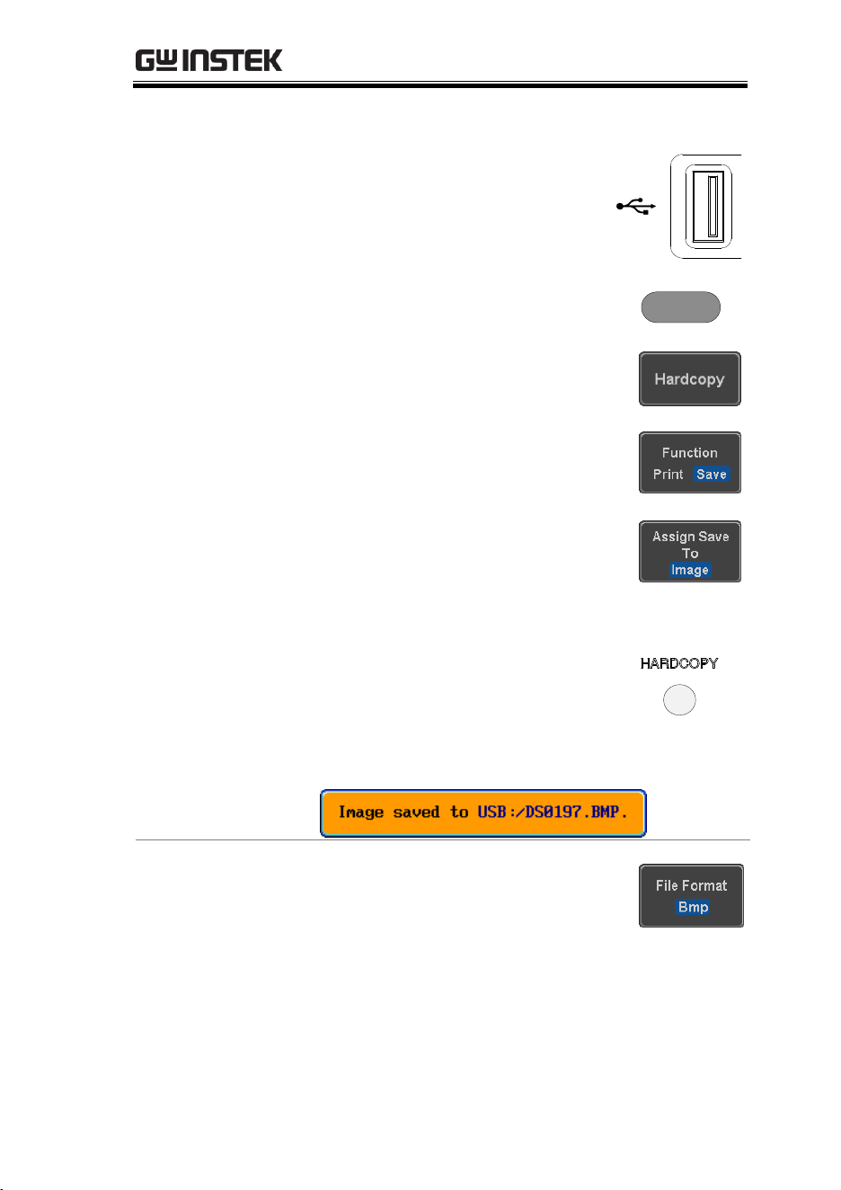
HARDCOPY KEY
337
Panel Operation
1. If you wish to save to USB,
connect a USB drive to the front
panel USB port, otherwise the
file will save to internal
memory.
Front
2V
2. Press the Utility key.
Utility
3. Press Hardcopy from the bottom
menu.
4. On the side menu, press Function
to select Save.
5. Press Assign Save To and select
which type of file will be saved
when the Hardcopy key is pressed.
File Type:
Image, Waveform, Setup, All
6. Press the Hardcopy key to save the
file*.
A message will appear when the
save is successful.
Image File
Format
7. For image files the file format can
be selected with the File Format
key.
Format:
BMP, PNG
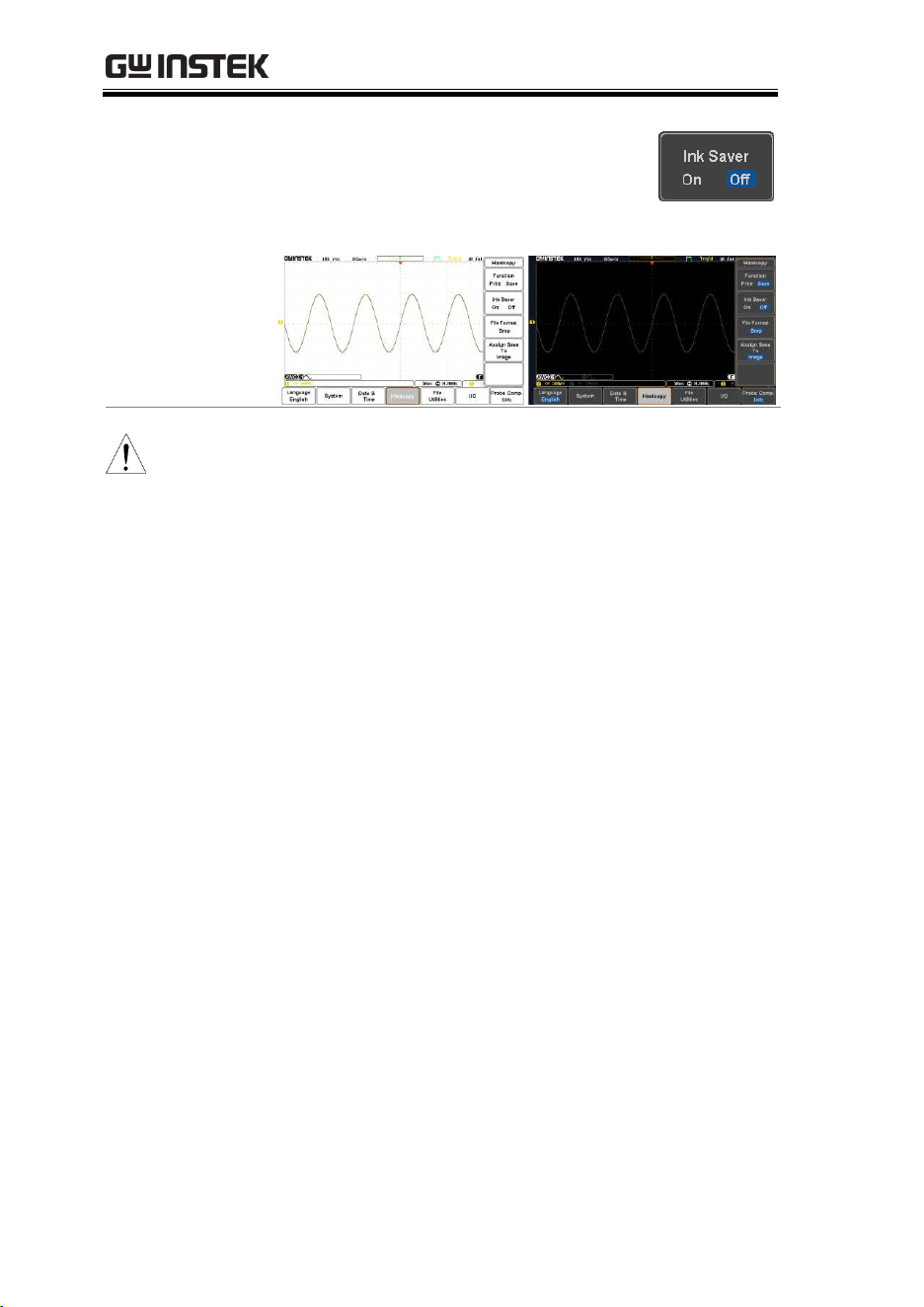
MDO-2000E series User Manual
338
Ink Saver
8. To have a white background for
image files, set Ink Saver to On.
Ink Saver On
Ink Saver Off
Note
*Each time the Hardcopy key is used to save
waveforms or setup files, the files are saved into a new
directory. The save directory is labeled ALLXXXX,
where XXXX is a number that is incremented with
each save. This directory is created in either the
internal memory or to a USB flash drive.

REMOTE CONTROL CONFIG
339
REMOTE CONTROL
CONFIG
This chapter describes basic configuration for
remote control. For a complete command list,
refer to the programming manual downloadable
from GW Instek website, www.gwinstek.com.
Interface Configuration .............................................340
Configure USB Interface ..................................................................... 340
USB Functionality Check .................................................................... 341
Configure the Ethernet Interface ...................................................... 341
Configure Socket Server ...................................................................... 343
Socket Server Functionality Check .................................................... 344
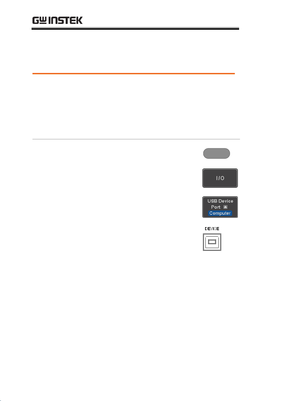
MDO-2000E series User Manual
340
Interface Configuration
Configure USB Interface
USB
Configuration
PC side connector
Type A, host
MDO-2000E side
connector
Type B, device
Speed
1.1/2.0
USB Class
CDC (communications device
class)
Panel Operation
1. Press the Utility key.
Utility
2. Press I/O from the bottom menu.
3. Press USB Device Port from the side
menu and select Computer.
4. Connect the USB cable to the rear
panel device port.
5. When the PC asks for the USB driver, select the
USB driver included on the accompanying User
Manual CD or download the driver from the
GW Instek website, www.gwinstek.com, in the
MDO-2000E Download section. The driver
automatically sets the MDO-2000E as a serial
COM port (Shown as VPO in the PORTS node).
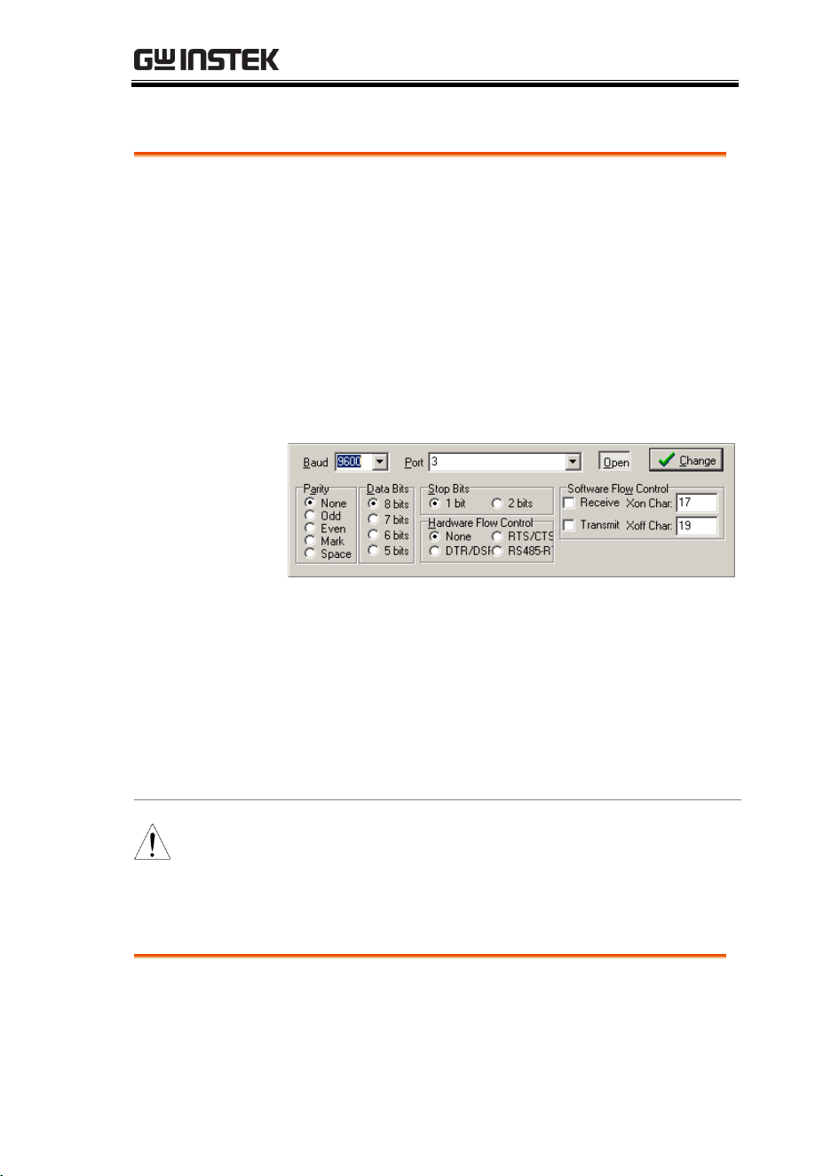
REMOTE CONTROL CONFIG
341
USB Functionality Check
Terminal
Application
Invoke a terminal application such as RealTerm.
Set the COM port, baud rate, stop bit, data bit, and
parity accordingly.
To check the COM port number and associated
port settings, see the Device Manager in the PC.
For Windows 7:
Control panel → Hardware and Sound→ Device
Manager
Example: Configuring RealTerm:
Functionality
Check
Key in this query command via the terminal
application.
*idn?
This should return the Manufacturer, Model
number, Serial number, and Firmware version in
the following format.
GW,MDO-2xxxE,PXXXXXX,V1.00
Note
For further details about remote control and remote
commands, please see the programming manual,
available on the GW Instek website.
Configure the Ethernet Interface
Ethernet
Configuration
MAC Address
Domain Name
Instrument Name
DNS IP Address
User Password
Gateway IP Address
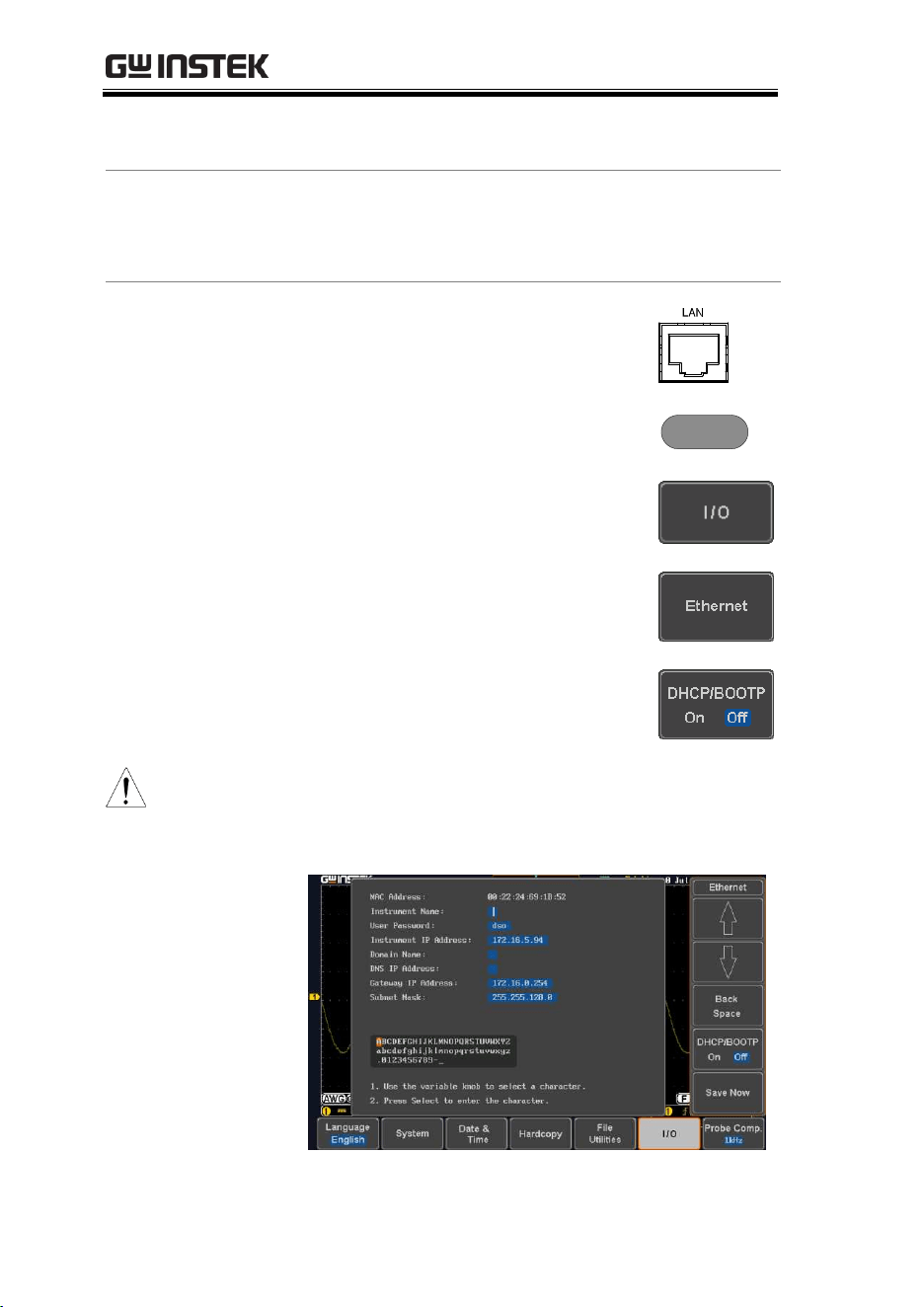
MDO-2000E series User Manual
342
Instrument IP
Address
Subnet Mask
Background
The Ethernet interface is used for remote control
using a socket server connection. For details,
please see the Socket Server section on page 343.
Panel Operation
1. Connect the Ethernet cable to the
LAN port on the rear panel.
2. Press the Utility key.
Utility
3. Press I/O from the bottom menu.
4. Press Ethernet from the side menu.
5. Set DHCP/BOOTP to On or Off
from the side menu.
Note
IP addresses will automatically be assigned with
DHCP/BOOTP set to on. For Static IP Addresses,
DHCP/BOOTP should be set to off.
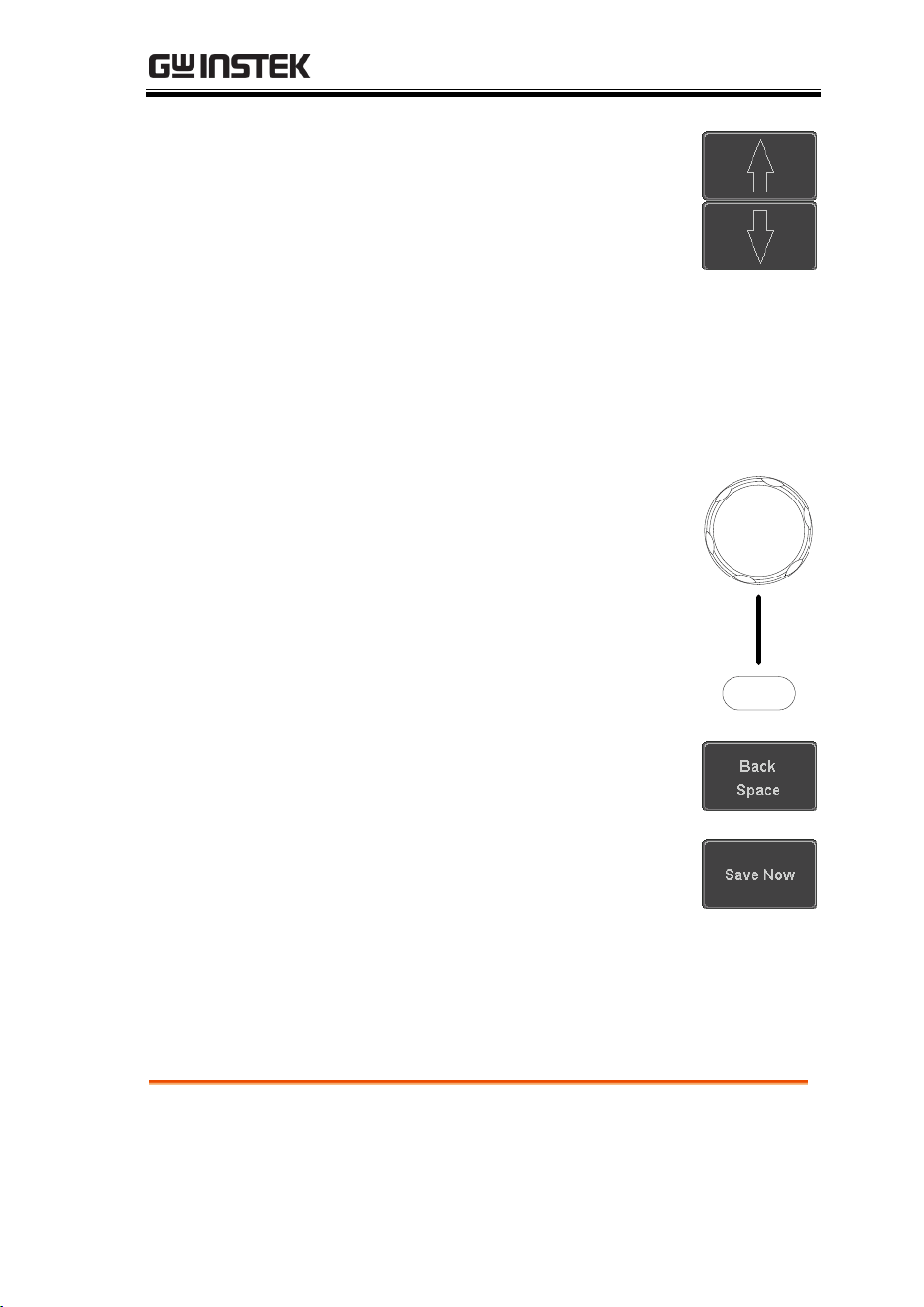
REMOTE CONTROL CONFIG
343
6. Use the Up and Down arrows on
the side menu to navigate to each
Ethernet configuration item.
Items
MAC Address, Instrument Name,
User Password, Instrument IP
Address, Domain Name, DNS IP
Address, Gateway IP Address,
Subnet Mask
7. Use the Variable knob to highlight a
character and use the Select key to
choose a character.
Select
VARIABLE
Press Backspace to delete a
character.
Press Save Now to save the
configuration. Complete will be
displayed when successful.
Configure Socket Server
The MDO-2000E supports socket server functionality for direct
two-way communication with a client PC or device over LAN. By
default, the Socket Server is off.
Configure Socket
Server
1. Configure the IP address for the
MDO-2000E.
Page 341
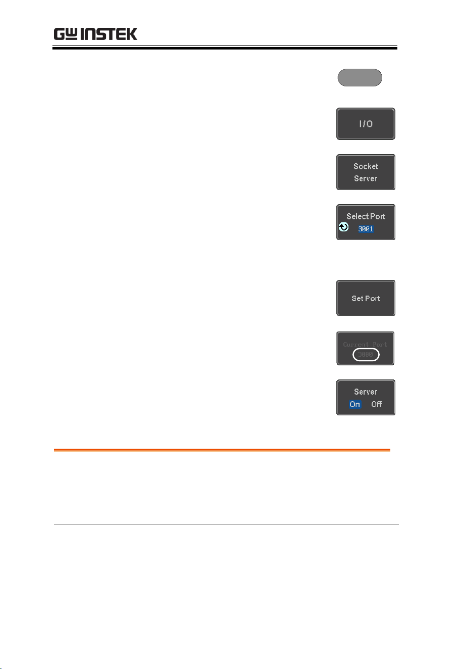
MDO-2000E series User Manual
344
2. Press the Utility key.
Utility
3. Press I/O from the bottom menu.
4. Press Socket Server from the side
menu.
5. Press Select Port and choose the
port number with the Variable
knob.
Range
1024~65535
6. Press Set Port to confirm the port
number.
7. The Current Port icon will update
to the new port number.
8. Press Server and turn the socket
server On.
Socket Server Functionality Check
NI Measurement
and Automation
Explorer
To test the socket server functionality, National
Instruments Measurement and Automation
Explorer can be used. This program is available on
the NI website, www.ni.com.
Operation
1. Configure the IP address for the
MDO-2000E.
Page 341
2. Configure the socket port.
Page 343
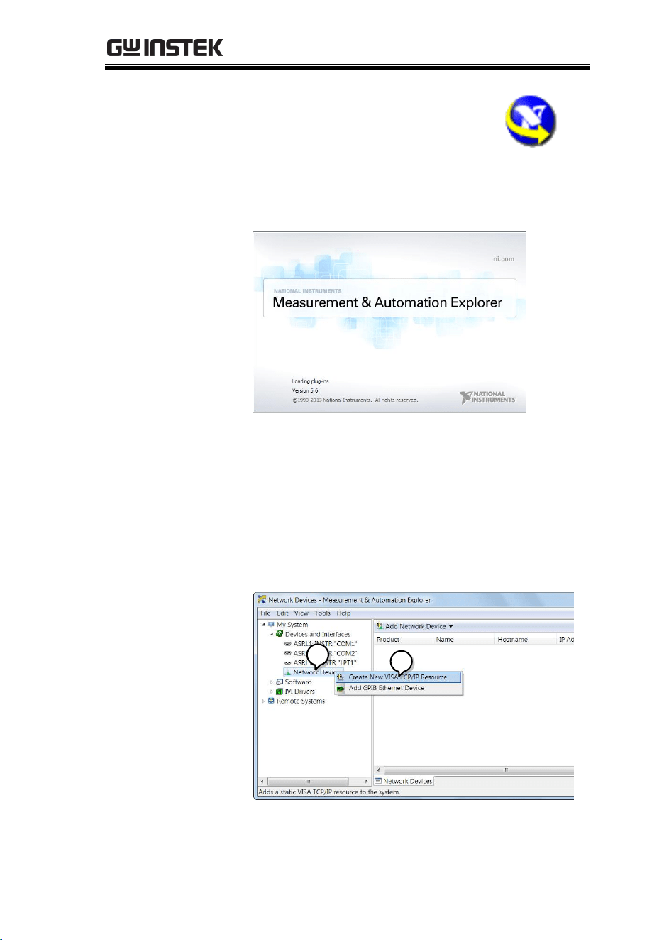
REMOTE CONTROL CONFIG
345
3. Start the NI Measurement and
Automation Explorer (MAX)
program. Using Windows, press:
Start>All Programs>National
Instruments>Measurement & Automation
4. From the Configuration panel access;
My System>Devices and Interfaces>Network
Devices
5. Right click Network Devices and select Create
New Visa TCP/IP Resource…
4
5
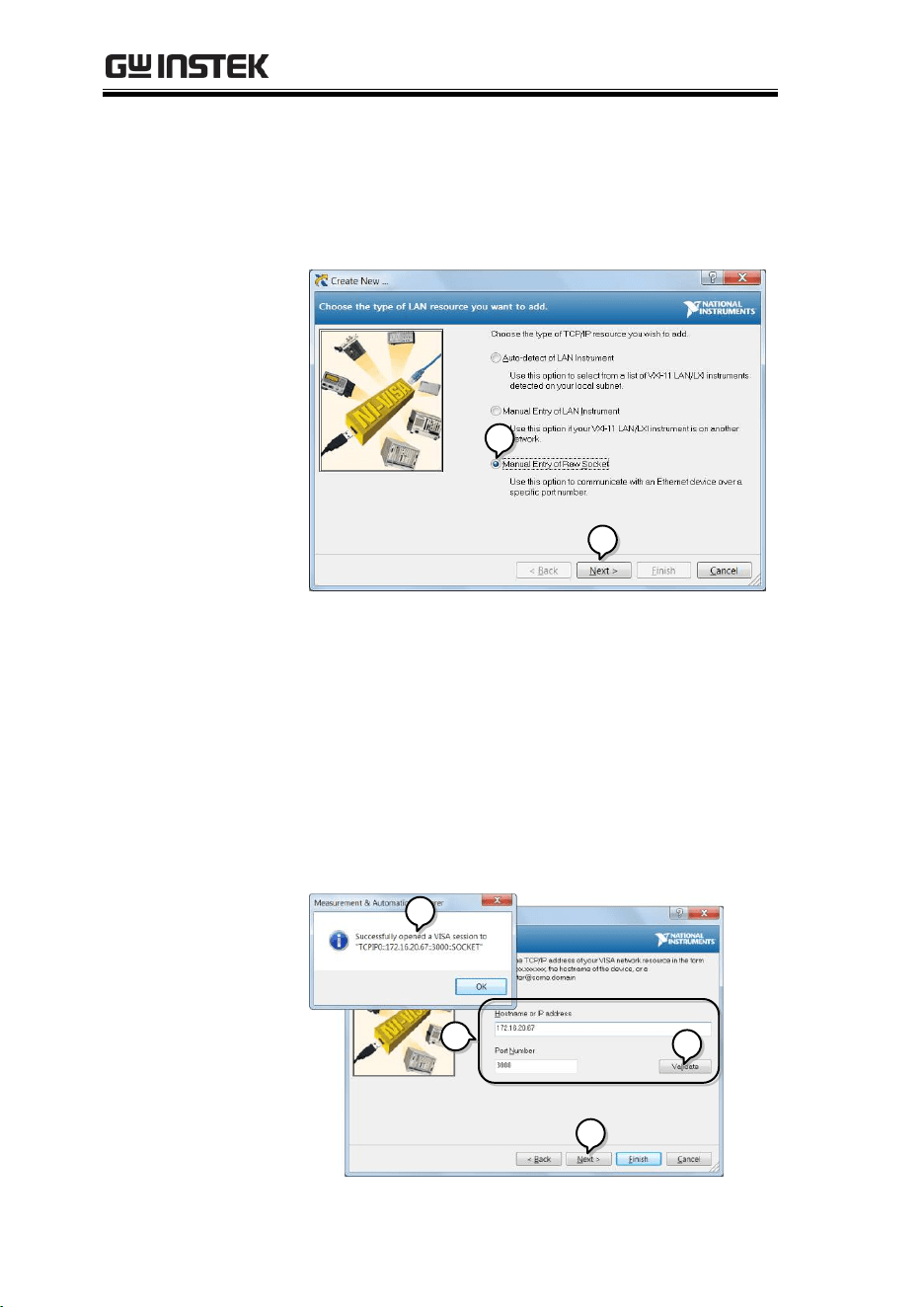
MDO-2000E series User Manual
346
6. Select Manual Entry of Raw Socket from the
popup window.
7. Click Next.
6
7
8. Enter the MDO-2000E’s IP address and socket
port number.
9. Click Validate.
10. A popup will appear to tell you if a VISA socket
session was successfully created.
11. Click Next.
10
11
8
9
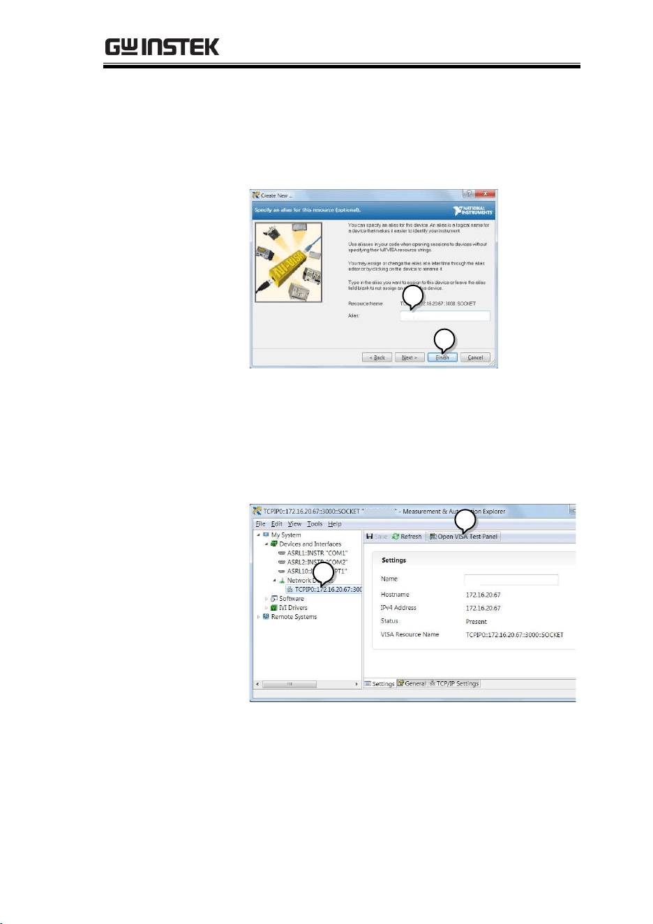
REMOTE CONTROL CONFIG
347
12. Choose an alias for the socket connection if you
like.
13. Click Finish to finish the configuration.
12
13
MSO
MDO-2000EG
14. The MDO-2000E will now appear under
Network Devices in the Configuration Panel.
Functionality
Check
15. Click the Open Visa Test Panel to send a remote
command to the MDO-2000E.
14
15
MSO
MDO-2000EG
MDO-2000EG
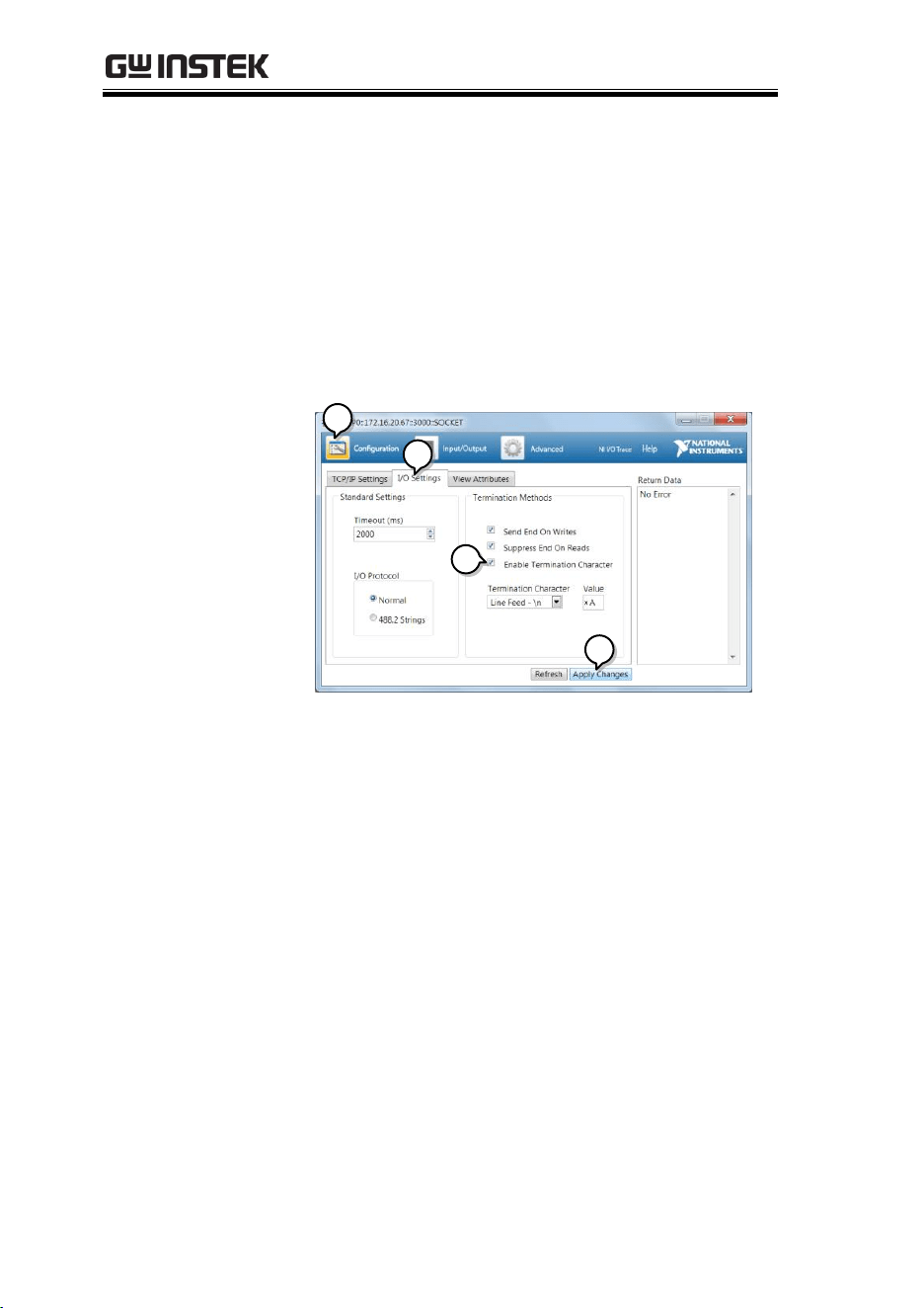
MDO-2000E series User Manual
348
16. Click on the Configuration icon.
17. Select the I/O Settings tab.
18. Mark the Enable Termination Character checkbox.
Make sure the termination character is a line
feed (/n, value: xA).
19. Click Apply Changes.
16
17
18
19
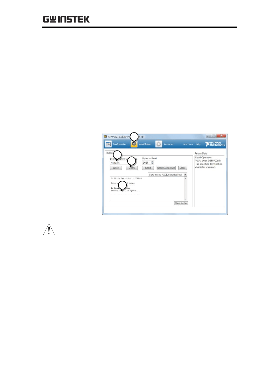
REMOTE CONTROL CONFIG
349
20. Click the Input/Output icon.
21. Make sure the *IDN? query is selected in the
Select or Enter Command drop box.
22. Click on Query.
23. The manufacturer, model number, serial
number and firmware version will be displayed
in the buffer. For example:
GW,MDO-2202EG,PXXXXXX,V1.00
20
21
22
23
MSO
GW, MDO-2202EG, PXXXX XX, V1.00\N
Note
For further details about remote control and remote
commands, please see the programming manual.

MDO-2000E series User Manual
350
MAINTENANCE
Three types of maintenance operations are
available: Signal Path Compensation, Vertical
Accuracy Calibration and Probe Compensation.
Run these operations when using the MDO-
2000E in a new environment.
How to use the SPC function............................................................. 351
Vertical Accuracy Calibration ............................................................. 352
Probe Compensation ........................................................................... 353
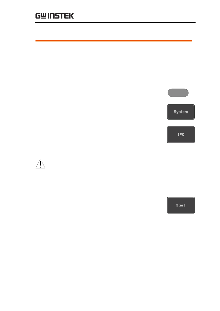
MAINTENANCE
351
How to use the SPC function
Background
Signal Path Compensation (SPC) is used to
compensate the internal signal path due to
ambient temperature. SPC is able to optimize the
accuracy of the oscilloscope with respect to the
ambient temperature.
Panel Operation
1. Press the Utility key.
Utility
2. Press System from the bottom
menu.
3. Press SPC from the side menu. A
message showing a brief
introduction to SPC appears on the
screen.
Note
Disconnect all probes and cables from all channels
before calibrating.
The DSO needs to be warmed up for at least 30
minutes before using the SPC function.
4. Press Start on the side menu to
start SPC calibration.
5. The SPC Calibration will proceed one channel
at a time, from channel 1 to channel 4*.
*Channels 1 to 2 for 2 channel models only.
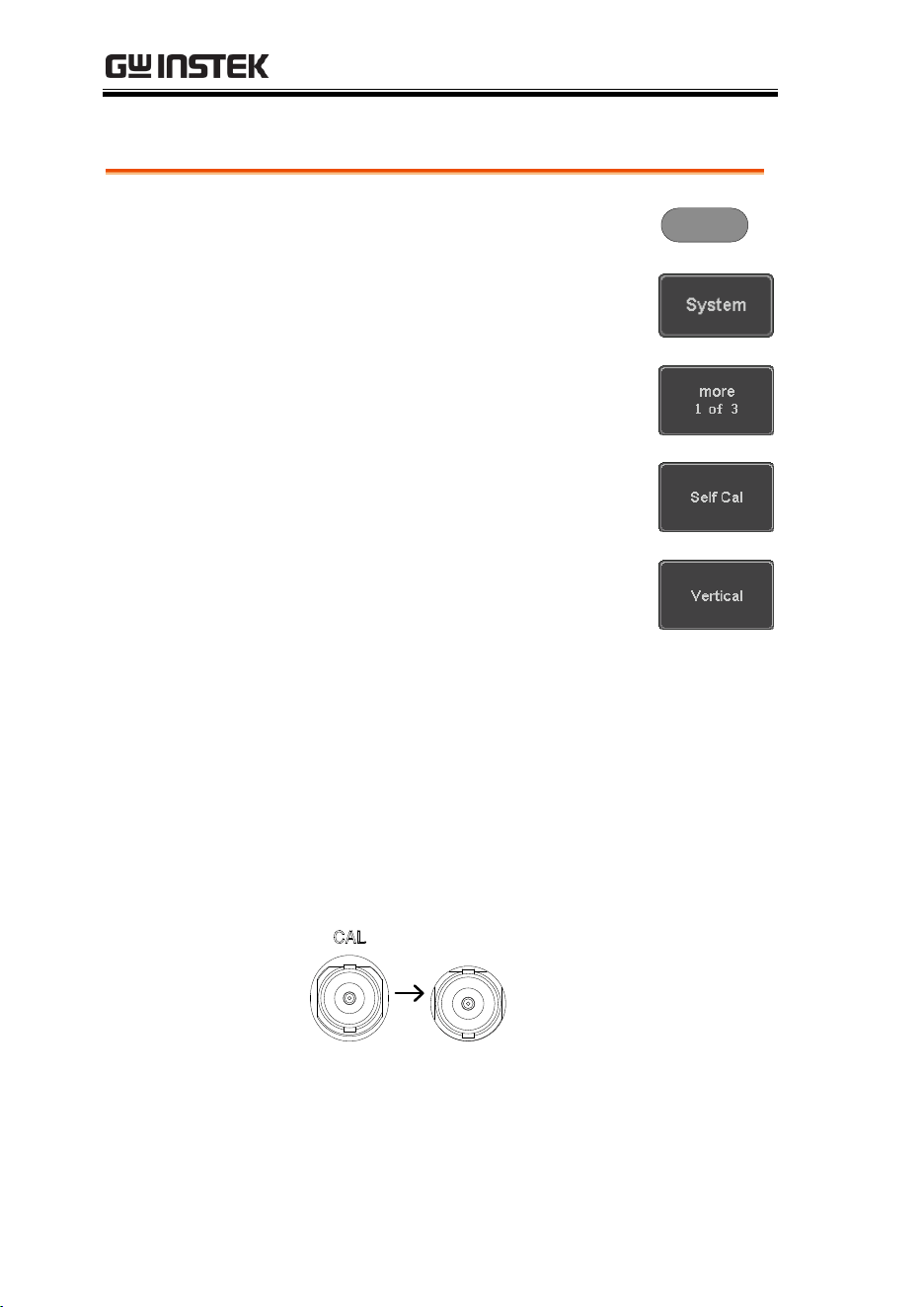
MDO-2000E series User Manual
352
Vertical Accuracy Calibration
Panel Operation
1. Press the Utility key.
Utility
2. Press System from the bottom
menu.
3. Press more 1 of 3 from the side
menu.
4. Press Self Cal on the side menu.
5. Press Vertical on the side menu.
6. A message appears to “Now performing
vertical calibration…
CH1
Connect the CAL output to channel, then press
the Vertical key”.
7. Connect the calibration signal from the rear
panel to the Channel 1 input with a BNC cable.
CH1

MAINTENANCE
353
8. Press Vertical again after
connecting CAL to the channel 1
input.
The calibration for Channel 1 starts and ends
automatically, in less than 5 minutes. A
message is displayed when the calibration
procedure has ended.
9. Repeat the above step for Channel 2, 3* and 4*
when prompted.
*4 channel models only.
10. When the calibration for all channels has
completed, the display goes back to the default
state.
Probe Compensation
Panel Operation
1. Connect the probe between the Channel 1 input
and the probe compensation output (default set
as 2Vp-p, 1kHz square wave) on the front
panel. Set the probe attenuation to x10.
2. Alternatively, the probe compensation
frequency can be changed. See page 194 for
details.
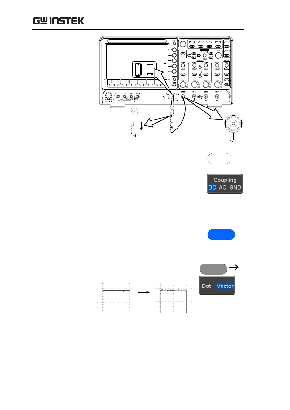
MDO-2000E series User Manual
354
x1
x10
X
10
X
1
CH1
2V
3. Press the CH1 key to activate CH1.
CH1
4. Set the Coupling to DC from the
bottom menu.
5. Set the Probe attenuation to
Voltage, 10X.
Page 116
6. Press the Autoset key. The
compensation signal appears on
the display.
Autoset
7. Press the Display key, then set
the display type to Vector.
Display

MAINTENANCE
355
8. Turn the adjustment point on the probe to
make the waveform as square as possible.
Under
Compensation
Normal
Over
Compensation

MDO-2000E series User Manual
356
FAQ
•
I connected the signal but it does not appear on the display.
•
I want to remove the (Measurement result / FFT result / Help
contents) from the display.
•
The waveform does not update (frozen).
•
The probe waveform is distorted.
•
Autoset does not catch the signal well.
•
The display image printout is too dark on the background.
•
The date and time settings are not correct.
•
The accuracy does not match the specification.
I connected the signal but it does not appear on the display.
Make sure you have activated the channel by pressing the Channel
key (the channel key lights up).
I want to remove the (Measurement result / FFT result /
Help contents) from the display.
To clear automatic measurement results, press the Measure key,
select Remove Measurement and choose Remove All. See page 52.
To clear individual measurements from the screen, press the
Measure key, select Display All and choose Off. See page 53.
To clear the FFT result, press the Math key twice. See page 67 for
details.
To clear the Help result, press the Help key again. See page 37 for
details.

FAQ
357
The waveform does not update (frozen).
Press the Run/Stop key to unfreeze the waveform. See page 42 for
details.
If this does not help, the trigger mode might be set to Single. Press
the Single key to exit Single mode. See page 146 for Single trigger
details.
The probe waveform is distorted.
You might need to compensate the probe. For details, see page 353.
Autoset does not catch the signal well.
The Autoset function cannot catch signals under 10mV or 20Hz.
Please use the manual operation. See page 40 for Autoset details.
The display image printout is too dark on the background.
Use the Ink Saver function which reverses the background color.
For details, see page 336.
The date and time settings are not correct.
For date and time setting details, please see page 194. If it does not
help, the internal battery controlling the clock might be worn out.
Contact your dealer or GW Instek.
The accuracy does not match the specification.
Make sure the device is powered On for at least 30 minutes, within
+20°C~+30°C. This is necessary to stabilize the unit to match the
specification.
For more information, contact your local dealer or GW Instek at
www.gwinstek.com / marketing@goodwill.com.tw.

MDO-2000E series User Manual
358
APPENDIX
Updating the Firmware ............................................ 359
MDO-2000E Series Specifications ............................ 361
Model-specific ....................................................................................... 361
Common ................................................................................................ 361
Probe Specifications ................................................ 368
GTP-070B-4 ................................................................................ 368
GTP-100B-4 ................................................................................ 368
GTP-200B-4 ................................................................................ 369
Dimensions ............................................................. 370
Declaration of Conformity ........................................ 371
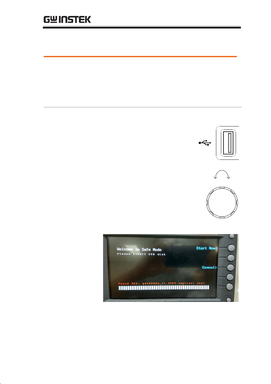
APPENDIX
359
Updating the Firmware
Background
New firmware can be downloaded from our
website in the MDO products section.
Place a copy of the firmware file (xxx.upg) onto the
root directory of a USB flash disk.
Panel Operation
1. Put the USB drive that contains
the firmware into the front
panel USB port.
Front panel
2V
2. Power up the oscilloscope and at
the same time, rotating the
“VARIABLE” knob several times
until the oscilloscope boot in the
firmware upgrade mode as in the
snapshot below.
3. When the firmware file of USB flash disk has
been recognized by oscilloscope, a message of
“Found UPG: xxx.upg” will appear on the
lower corner.
VARIABLE
Up Down
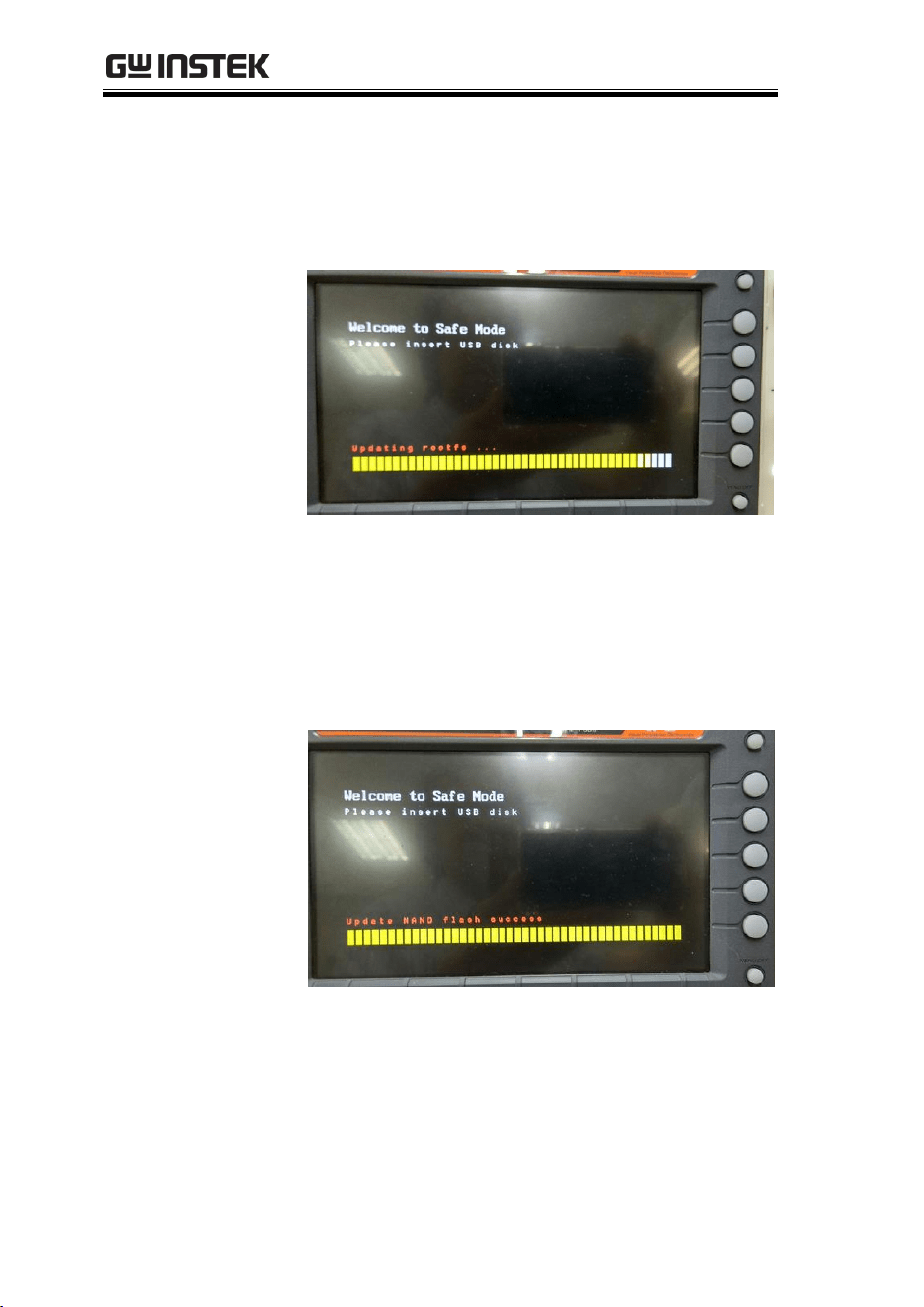
MDO-2000E series User Manual
360
4. Press the “Start Now” (F1) key. The
oscilloscope will automatically start upgrading
the firmware. Or press the “Cancel” (F3) key to
quit the firmware upgrading procedure.
5. When the status indicator shows the complete
status (status indicator in yellow completely)
and a message of “Update NAND flash
success” will appear on the top of status
indicator. The firmware upgrading procedure is
completed.
6. Restart the oscilloscope manually.
Check the firmware version by pressing the
“Utility” “System” “System Info”. The
system information screen that it is being
updated.

APPENDIX
361
MDO-2000E Series Specifications
The specifications apply when the MDO-2000E series is powered
on for at least 30 minutes under +20°C~+30°C.
Model-specific
MDO-2072EG/X/C/S
Channels
2 + Ext
Bandwidth
DC ~ 70MHz (-3dB)
Rise Time
5ns (Calculated)
Bandwidth Limit
20MHz
MDO-2074EG/X/C/S
Channels
4
Bandwidth
DC ~ 70MHz (-3dB)
Rise Time
5ns (Calculated)
Bandwidth Limit
20MHz
MDO-2102EG/X/C/S
Channels
2 + Ext
Bandwidth
DC ~ 100MHz (-3dB)
Rise Time
3.5ns (Calculated)
Bandwidth Limit
20MHz
MDO-2104EG/X/C/S
Channels
4
Bandwidth
DC ~ 100MHz (-3dB)
Rise Time
3.5ns (Calculated)
Bandwidth Limit
20MHz
MDO-2202EG/X/C/S
Channels
2 + Ext
Bandwidth
DC ~ 200MHz (-3dB)
Rise Time
1.75ns (Calculated)
Bandwidth Limit
20MHz/100MHz
MDO-2204EG/X/C/S
Channels
4
Bandwidth
DC ~ 200MHz (-3dB)
Rise Time
1.75ns (Calculated)
Bandwidth Limit
20MHz/100MHz
Common
Vertical
Sensitivity
Resolution
8 bit
:1mV*~10V/div
*: When the vertical scale is set to
1mV/div, the bandwidth limit will be
set to 20MHz automatically.
Input Coupling
AC, DC, GND
Input Impedance
1MΩ// 16pF approx.
DC Gain Accuracy*
1mV: ±5% full scale
≥2mV: ±3% full scale

MDO-2000E series User Manual
362
Polarity
Normal & Invert
Maximum Input Voltage
300Vrms, CAT I
Offset Position Range
1mV/div ~ 20mV/div : ±0.5V
50mV/div ~ 200mV/div : ±5V
500mV/div ~ 2V/div : ±25V
5V/div ~ 10V/div : ±250V
Waveform Signal
Process
+, -, ×, ÷, FFT, User Defined Expression
FFT: Spectral magnitude. Set FFT
Vertical Scale to Linear RMS or dBV
RMS or dBm, and FFT Window to
Rectangular, Hamming, Hanning or
Blackman.
Trigger
Source
CH1, CH2, CH3*, CH4*, Line, EXT**
*four channel models only.
**two channel models only.
Trigger Mode
Auto (supports Roll Mode for 100
ms/div and slower), Normal, Single
Sequence
Trigger Type
Edge, Pulse Width(Glitch), Video,
Pulse Runt, Rise & Fall(Slope),
Timeout, Alternate, Event-
Delay(1~65535 events), Time-
Delay(Duration, 4nS~10S), Bus
Holdoff range
4nS to 10S
Coupling
AC, DC, LF rej., Hf rej., Noise rej.
Sensitivity
1div
External
Trigger
Range
±15V
Sensitivity
DC ~ 100MHz Approx. 100mV
100MHz ~ 200MHz Approx. 150mV
Input Impedance
1MΩ±3%~16pF
Horizontal
Time base Range
1ns/div ~ 100s/div (1-2-5 increments)
ROLL: 100ms/div ~ 100s/div
Pre-trigger
10 div maximum
Post-trigger
2,000,000 div maximum.
Timebase Accuracy
±50 ppm over any ≥ 1 ms time interval
Real Time Sample Rate
1GSa/s max. (4ch models);
1GSa/s per channel (2ch models)
Record Length
Max. 10Mpts
Acquisition Mode
Normal, Average, Peak Detect, Single
Peak Detection
2nS (typical)
Average
selectable from 2 to 256
X-Y Mode
X-Axis Input
Channel 1; Channel 3*
*four channel models only
Y-Axis Input
Channel 2; Channel 4*
*four channel models only

APPENDIX
363
Phase Shift
±3° at 100kHz
Cursors and
Measurement
Cursors
Amplitude, Time, Gating available;
Unit: Seconds(s), Hz (1/s), Phase
(degree), Ratio (%).
Automatic Measurement
38 sets: Pk-Pk, Max, Min, Amplitude,
High, Low, Mean, Cycle Mean, RMS,
Cycle RMS, Area, Cycle Area,
ROVShoot, FOVShoot, RPREShoot,
FPREShoot, Frequency, Period,
RiseTime, FallTime, +Width, -Width,
Duty Cycle, +Pulses, -Pulses, +Edges, -
Edges, %Flicker, Flicker Idx ,FRR, FRF,
FFR, FFF, LRR, LRF, LFR, LFF, Phase.
Cursors measurement
Voltage difference between cursors
(∆V)Time difference between cursors
(∆T)
Auto counter
6 digits, range from 2Hz minimum to
the rated bandwidth
Control Panel
Function
Autoset
Single-button, automatic setup of all
channels for vertical, horizontal and
trigger systems, with undo Autoset
Save Setup
20set
Save Waveform
24set
AWG
General
Channels
2
Sample Rate
200MSa/s
Vertical Resolution
14 bits
Max. Frequency
25 MHz
Waveforms
Sine, Square, Pulse, Ramp, DC, Noise
Sinc, Gaussian, Lorentz, Exponential
Rise, Exponential Fall, Haversine,
Cardiac
Output Range
20 mVpp to 5 Vpp, HighZ;
10 mVpp to 2.5 Vpp, 50Ω
Output Resolution
1mV
Output Accuracy
2% (1 kHz)
Offset Range
±2.5 V, HighZ; ±1.25 V, 50 Ω
Offset Resolution
1mV
Sine
Frequency Range
100 mHz to 25 MHz
Flatness
(relative to 1 kHz)
±0.5 dB < 15MHz;
±1dB 15MHz~25MHz
Harmonic Distortion
-40 dBc
Stray (Non-harmonic)
-40 dBc

MDO-2000E series User Manual
364
Total Harmonic
Distortion
1%
S/N Ratio
40 dB
Square/Pulse
Frequency Range
Square: 100 mHz to 15 MHz
Rise/Fall Time
< 15ns
Overshoot
< 3 %
Duty Cycle
Square: 50%
Pulse: 0.4% to 99.6%
Min. Pulse Width
30ns
Jitter
500 ps
Ramp
Frequency Range
100 mHz to 1MHz
Linearity
1%
Symmetry
0 to 100%
Spectrum
Analyzer
Frequency Range
DC~500MHz (Max, Max.
bandwidth~500MHz uncalibrated)
Span
1kHz~500MHz (Max.)
Resolution Bandwidth
1Hz~500MHz (Max.)
Reference Level
-50dBm to +40dBm in steps of 5dBm
Vertical Units
dBV RMS; Linear RMS; dBm
Vertical Position
-12divs to +12divs
Vertical Scale
1dB/div to 20dB/div in a 1-2-5
Sequence
Displayed Average Noise
Level
1V/div -50dBm, Avg : 16
100mV/div -70dBm, Avg : 16
10mV/div -90dBm, Avg : 16
Spurious Response
2nd harmonic distortion < 40dBc
3rd harmonic distortion < 45dBc
Frequency Domain Trace
Types
Normal; Max Hold; Min Hold; Average
(2 ~ 256)
Detection Methods
Sample; +Peak; -Peak; Average
FFT Windows
FFT Factor:
Hanning 1.44
Rectangular 0.89
Hamming 1.30
Blackman 1.68

APPENDIX
365
DMM
Reading
5,000 counts
CAT II 600Vrms, CAT III 300Vrms
Below are the basic conditions required
to operate the DMM within
specifications:
*Calibration: Yearly.
*Operating Temperature Specification:
18~28˚C (64.4~82.4˚F).
*Relative humidity: 80%. (Non
condensing)
*Accuracy: ± (% of Reading + % of
Range).
*AC measurement are based on a 50%
duty cycle.
DC Voltage
Range
50mV, 500mV, 5V, 50V, 500V, 1000V,
6 ranges
Accuracy
50mV, 500mV, 5V, 50V, 500V, 1000V :
±(0.1% + 0.1%)
Input Impedance
10M Ω
DC Current
Range
50mA, 500mA, 10A, 3 ranges
Accuracy
50mA~500mA : ±(0.5% + 0.1%) ;
10A : ±(0.5% + 0.5%)
AC Voltage
Range
50mV, 500mV, 5V, 50V, 500V, 700V,
5 ranges
Accuracy
50mV, 500mV, 5V, 50V, 700V :
±(1.5% + 1.5%) at 50Hz~1kHz
AC Current
Range
50mA, 500mA, 10A, 3 ranges
Accuracy*
50mA, 500mA: ±(1.5% + 0.1%) at
50Hz~1kHz;
10A: ±(3% + 0.5%) at 50Hz~1kHz
*Measure range: >10mA
Resistance*
Range
500Ω, 5kΩ, 50kΩ, 500kΩ, 5MΩ, 5
range
Accuracy
500Ω, 5kΩ, 50kΩ, 500kΩ, 5MΩ:
±(0.3% + 0.01%)
*Measure range: 50Ω to 5MΩ
Diode Test
Maximum forward voltage 1.5V,
Open voltage 2.8V

MDO-2000E series User Manual
366
Temperature (Thermocouple)*
Range
-50°C - + 1000°C
Resolution
0.1°C
* Specifications do not include probe accuracy.
Continuity Beeper
15 Ω
Power Supply
Output Channel
Ch1 & Ch2
Output Voltage Range
1.0 V~ 5.0 V
Output Current (max.)
1 A
Voltage Step
0.1 V Continuously Adjustable
Output Voltage Accuracy
+/- 3%
Ripple and Noise
50mVrms
Logic Analyzer
Sample Rate
1GSa/s
Bandwidth
200MHz
Record Length
Per Channel 10M points (max)
Total Memory
2G bits
Input Channels
16 Digital (D15-D0)
Trigger Type
Edge, pattern, Pulse Width, Serial Bus
(I2C, SPI, UART, CAN, LIN), Parallel
Bus
Thresholds Quad
Settable thresholds for:
D0-D3, D4-D7, D8-11, D12-15
Thresholds Selections
TTL, CMOS (5V, 3.3V, 2.5V), ECL,
PECL, 0V, User-defined.
User-defined Threshold
Range
±5V
Maximum Input Voltage
±40V
Minimum Voltage Swing
±250 mV
Vertical Resolution
1 bit
Display
TFT LCD Type
8" TFT LCD WVGA color display
Display Resolution
800 horizontal × 480 vertical pixels
(WVGA)
Interpolation
Sin(x)/x
Waveform Display
Dots, vectors, variable persistence
(16ms~4s), infinite persistence
Waveform Update Rate
120,000 waveforms per second,
maximum
Display Graticule
8 x 10 divisions
Display Mode
YT, XY
Interface
USB Port
USB 2.0 High-speed host port X1, USB
High-speed 2.0 device port X1
Ethernet Port (LAN)
RJ-45 connector, 10/100Mbps with HP
Auto-MDIX
Go-NoGo BNC
5V Max/10mA TTL open collector
output

APPENDIX
367
Kensington Style Lock
Rear-panel security slot connects to
standard Kensington-style lock.
Miscellaneous
Multi-language menu
Available
Operation Environment
Temperature: 0°C to 50°C. Relative
Humidity ≤ 80% at 40°C or below; ≤
45% at 41°C ~ 50°C.
On-line help
Available
Time clock
Time and Date, Provide the Date/Time
for saved data
Dimensions
380mmX208mmX127.3mm
Weight
3kg

MDO-2000E series User Manual
368
Probe Specifications
GTP-070B-4
Applicable to: MDO-2072EG/2072EX & MDO-2074EG/2074EX
Position x10
Attenuation Ratio
10:1
Bandwidth
DC to 70MHz
Input Resistance
10MΩ when used with oscilloscopes
with 1MΩ input
Input Capacitance
14.5pF to 17.5pF
Compensation Range
10pF to 35pF
Max. Input Voltage
≤600V DC + ACpk
Position x1
Attenuation Ratio
1:1
Bandwidth
DC to 10MHz
Input Resistance
1MΩ (oscilloscope input resistance)
Input Capacitance
85pF to 115pF
Max. Input Voltage
≤200V DC + ACpk
Operating Cond.
Temperature
-10°C to 50°C
Relative Humidity
≤85%
GTP-100B-4
Applicable to: MDO-2102EG/2102EX & MDO-2104EG/2104EX
Position X10
Attenuation Ratio
10:1
Bandwidth
DC to 100MHz
Input Resistance
10MΩ when used with oscilloscopes
with 1MΩ input.
Input Capacitance
14.5pF to 17.5pF
Compensation Range
5pF to 30pF
Max. Input Voltage
≤600V DC + ACpk
Position X1
Attenuation Ratio
1:1
Bandwidth
DC to 10MHz
Input Resistance
1MΩ (oscilloscope input resistance)
Input Capacitance
85pF to 115pF
Max. Input Voltage
≤200V DC + ACpk
Operating Cond.
Temperature
–10°C to 50°C
Relative Humidity
≤85%

APPENDIX
369
GTP-200B-4
Applicable to: MDO-2202EG/2202EX & MDO-2204EG/2204EX
Position X10
Attenuation Ratio
10:1
Bandwidth
DC to 200MHz
Input Resistance
10MΩ when used with oscilloscopes
with 1MΩ input.
Input Capacitance
10.5pF to 17.5pF
Compensation Range
5pF to 30pF
Max. Input Voltage
≤600V DC + ACpk
Position X1
Attenuation Ratio
1:1
Bandwidth
DC to 10MHz
Input Resistance
1MΩ (oscilloscope input resistance)
Input Capacitance
65pF to 105pF
Max. Input Voltage
≤200V DC + ACpk
Operating Cond.
Temperature
–10°C to 50°C
Relative Humidity
≤85%
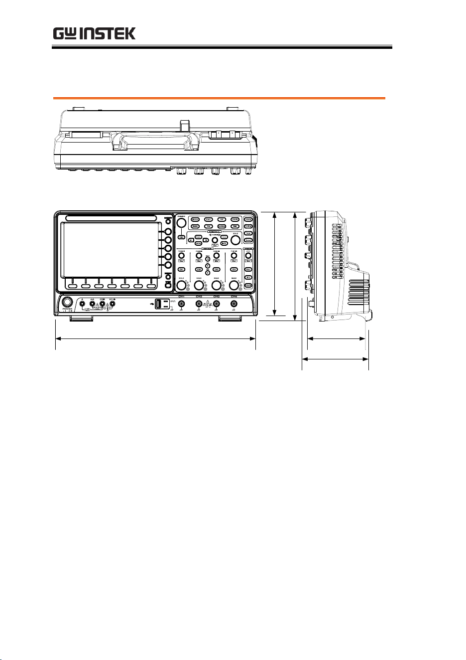
MDO-2000E series User Manual
370
Dimensions
384.0
198.0
208.0
111.0
127.3
APPENDIX
371
Declaration of Conformity
We
GOOD WILL INSTRUMENT CO., LTD.
declare that the below mentioned product
Type of Product: Mixed-Domain oscilloscope
Model Number: MDO-2072EG, MDO-2072EX, MDO-2074EG,
MDO-2074EX, MDO-2102EG, MDO-2102EX,
MDO-2104EG, MDO-2104EX, MDO-2202EG,
MDO-2202EX, MDO-2204EG, MDO-2204EX
are herewith confirmed to comply with the requirements set out in the
Council Directive on the Approximation of the Law of Member States
relating to EMC: 2014/30/EU, LVD: 2014/35/EU, WEEE: 2012/19/EU and
RoHS: 2011/65/EU.
For the evaluation regarding the Electromagnetic Compatibility and Low
Voltage Directive, the following standards were applied:
◎ EMC
EN 61326-1 :
EN 61326-2-1:
Electrical equipment for measurement, control and laboratory use –
– EMC requirements (2013)
Conducted and Radiated Emissions
EN 55011: 2016
Electrical Fast Transients
EN 61000-4-4:2012
Current Harmonic
EN 61000-3-2: 2014
Surge Immunity
EN 61000-4-5: 2014
Voltage Fluctuation
EN 61000-3-3: 2013
Conducted Susceptibility
EN 61000-4-6: 2014
Electrostatic Discharge
EN 61000-4-2: 2009
Power Frequency Magnetic Field
EN 61000-4-8: 2010
Radiated Immunity
EN 61000-4-3: 2006+A1: 2008+A2: 2010
Voltage Dips/ Interrupts
EN 61000-4-11: 2004
Low Voltage Equipment Directive 2014/35/EU
Safety Requirements
EN 61010-1:2010 (Third Edition)
EN 61010-2-030:2010 (First Edition)
GOODWILL INSTRUMENT CO., LTD.
No. 7-1, Jhongsing Road, Tucheng District, New Taipei City 236, Taiwan
Tel:
+886-2-2268-0389 Fax: +886-2-2268-0639
Web: http://www.gwinstek.com Email: marketing@goodwill.com.tw
GOODWILL INSTRUMENT (SUZHOU) CO., LTD.
No. 521, Zhujiang Road, Snd, Suzhou Jiangsu 215011, China
Tel:
+86-512-6661-7177 Fax: +86-512-6661-7277
Web: http://www.instek.com.cn Email: marketing@instek.com.cn
GOODWILL INSTRUMENT EURO B.V.
De Run 5427A, 5504DG Veldhoven, The Netherlands
Tel:
+31-(0)40-2557790 Fax: +31-(0)40-2541194
Email: sales@gw-instek.eu

MDO-2000E series User Manual
372
INDEX
AC coupling ............................. 111
AC Priority mode ...................... 41
Acquisition ................................. 80
average .......................................... 80
indicator ........................................ 26
peak detect .................................... 80
record length ................................. 83
sample............................................ 80
XY mode ........................................ 81
Advanced math
expression ..................................... 72
operation ....................................... 73
source ............................................. 72
Amplitude measurements ........ 47
APP
Data Log ...................................... 289
digital filter ................................. 291
DVM ............................................ 287
Go-NoGo ..................................... 282
mask ............................................. 293
overview ...................................... 280
run ................................................ 281
Area measurements .................. 47
Auto trigger .............................. 147
Auto-dim .................................... 99
Automatic measurement
Add measurement........................ 50
display all ...................................... 53
gated mode ................................... 52
High-Low ...................................... 54
overview ........................................ 46
Reference levels ............................ 58
remove measurement .................. 52
Statistics ......................................... 56
Autoset ........................................ 40
AC Priority mode ......................... 41
effect on channel ........................... 41
exception ....................................... 41
Fit Screen mode ............................ 41
AWG
AM ............................................... 222
channel activation ...................... 216
connection ................................... 215
Coupling and tracking .............. 243
Create new ARB waveform ...... 230
edit existing waveform ............. 231
FM ................................................ 224
FSK .............................................. 226
function edit ............................... 234
impedance .................................. 217
load ARB waveform .................. 239
normal edit ................................. 233
overview ..................................... 214
phase ........................................... 217
Save ARB waveform .................. 240
select waveform ......................... 218
specification ................................ 363
sweep .......................................... 228
turn on output ............................ 217
waveform settings ..................... 219
Bandwidth filter ....................... 113
Blackman window ..................... 70
Bus
CAN ............................................ 128
cursors ......................................... 141
encoding ..................................... 133
event tables ..........................135, 138
I
2
C ................................................ 124
labels ............................................ 139
LIN............................................... 129
parallel ........................................ 131
serial bus overview .................... 120
SPI ................................................ 126
threshold ..................................... 133
trigger settings
CAN ....................................... 172
I
2
C ........................................... 168
LIN .......................................... 175
Parallel ................................... 177

INDEX
373
SPI ............................................ 171
UART ...................................... 166
UART ........................................... 122
Channel ....................................... 39
status indicator .............................27
Control panel function
specification................................. 363
Conventions ............................... 31
Coupling mode ........................ 111
Cursor
horizontal ......................................60
specification................................. 363
vertical ...........................................63
Data logging ............................. 289
Date setting ............................... 194
indicator .........................................26
DC coupling ............................. 111
Declaration of conformity ....... 371
Default setup ............................ 321
contents ........................................ 322
effect on channel ...........................40
Delay measurements ................. 49
Deskew ...................................... 116
Digital channels
activation ..................................... 200
analog waveform ........................ 208
grouping ...................................... 203
labels ............................................ 209
position ........................................ 203
threshold ...................................... 207
vertical scale ................................ 207
Digital filter .............................. 291
Dimensions
diagram ........................................ 370
Display
AWG ............................................ 215
bus ................................................ 118
logic analyzer .............................. 199
search ........................................... 183
segmented memory ......................86
specification................................. 366
Spectrum Analyzer ..................... 249
Dots.............................................. 97
DVM .......................................... 287
Edge Trigger ............................. 154
EN61010
measurement category ...................5
pollution degree ............................. 6
Erase memory ........................... 193
Ethernet
interface ....................................... 341
Expand by ground/center ...... 114
External trigger......................... 146
input terminal ............................... 20
specification ................................ 362
FAQ ............................................ 356
FFT
horizontal cursor .......................... 62
vertical cursor ............................... 64
File
create folder ................................ 331
delete ........................................... 333
rename ......................................... 332
File navigation .......................... 330
File path ..................................... 331
Firmware update...................... 359
Firmware version ..................... 192
First time use .............................. 29
Fit Screen mode .......................... 41
Frequency measurements ......... 48
Front panel diagram ............ 14, 15
Go-NoGo
circuit diagram ........................... 286
Go-NoGo ................................... 282
timing .......................................... 286
Ground
coupling ...................................... 112
terminal ......................................... 21
Hamming window .................... 69
Hanning window ....................... 69
Holdoff ...................................... 153
Horizontal
basic operation ............................. 43
position ........................................ 102
scale ............................................. 103
specification ................................ 362
Image file format ...................... 304
Impedance................................. 112
Initialization ................................ 29
Input frequency indicator ......... 26
Intensity....................................... 98
Interface ..................................... 340
specification ................................ 366

MDO-2000E series User Manual
374
Invert waveform ...................... 112
Keys overview ........................... 15
Labels ........................................ 310
Language selection .................. 192
List of features ........................... 11
Logic Analyzer
overview ...................................... 198
probes .......................................... 198
Logic trigger ............................. 178
Mask .......................................... 293
auto mask .................................... 294
user-defined mask ...................... 298
Math
Advanced math overview ........... 72
basic ............................................... 67
FFT operation................................ 70
FFT overview ................................ 69
Mean measurements ................. 47
Memory bar
indicator ........................................ 26
Menu on/off ............................ 101
Miscellaneous
specification ................................ 367
Model differences ...................... 10
Normal trigger ......................... 147
NTSC ......................................... 150
Overshoot measurements......... 47
PAL............................................ 150
Peak measurements .................. 46
Peak to peak measurement ...... 46
Persistence .................................. 97
Play waveform ......................... 107
Printing
connection ................................... 335
hardcopy key .............................. 336
ink saver ...................................... 336
Probe
attenuation level ......................... 116
attenuation type ......................... 115
deskew ......................................... 116
Probe compensation ................ 353
Probe compensation frequency194
Pulse runt trigger .................... 161
Pulse measurements ................. 48
Pulse width trigger .................. 157
QR code reader function......... 195
Rear panel diagram ........... 23, 214
Recall ......................................... 321
default setup ............................... 321
reference ...................................... 327
setup ............................................ 325
waveform .................................... 324
Rectangular window ................. 70
Reduce any menu ...................... 35
Reduce lower menu ................... 35
Reduce side menu ...................... 34
Remote control ......................... 339
interface configuration .............. 340
Rise and fall trigger ................. 162
RMS measurements ................... 47
Roll mode .................................. 104
RS-232C
function check ............................ 341
Run/Stop ............................ 42, 100
horizontal position..................... 102
Horizontal scale ......................... 103
Safety Instructions
Caution symbol .............................. 4
Cleaning the instrument ............... 6
Disposal instructions ..................... 7
Ground symbol .............................. 4
Operation Environment ................ 6
Power on/off .................................. 6
UK power cord ............................... 8
Warning symbol ............................ 4
Save............................................ 313
hardcopy key .............................. 337
image ........................................... 314
setup ............................................ 318
waveform .................................... 316
Screen dimmer ........................... 99
Search
configuration .............................. 183
copying search events ............... 185
copying trigger events ............... 185
FFT Peak ..................................... 188
navigation ................................... 185
save marks .................................. 186
set/clear events .......................... 187
SECAM ...................................... 150
Segmented memory
configuration ................................ 87
infomation .................................... 95

INDEX
375
measurement .................................91
navigation ......................................90
overview ........................................85
play back ........................................91
run ..................................................88
Serial number ........................... 192
Service operation
about disassembly ..........................5
contact .......................................... 357
Setup
default contents .......................... 322
file format .................................... 307
Signal path compensation ...... 351
Single trigger mode ................. 147
Run/Stop .......................................42
Socket server
function check ............................. 344
Socket server
interface ....................................... 344
SPC ............................................ 351
Specifications ............................ 361
Spectrum Analyzer
bandwidth ................................... 259
center frequency ......................... 255
connections .................................. 250
cursors263, 268, 269, 270, 271, 272, 273
detection mode ........................... 254
Overview ..................................... 248
peak search .................................. 262
source ........................................... 251
span .............................................. 256
start and stop frequency ............ 257
trace options ................................ 252
vertical scale ................................ 260
window type ............................... 260
Spreadsheet file format ........... 305
Stop icon ..................................... 42
System information ................. 192
Tilt stand ..................................... 28
Time setting .............................. 194
indicator .........................................26
Trigger ....................................... 143
Bus
CAN ........................................ 172
I
2
C ............................................ 168
LIN .......................................... 175
Parallel .................................... 177
SPI ........................................... 171
UART ...................................... 166
edge ............................................. 154
holdoff ......................................... 153
indicator ........................................ 26
logic ............................................. 178
mode ............................................ 154
parameters .................................. 146
pulse runt .................................... 161
pulse width ................................. 157
Rise and fall ................................ 162
Single ............................................. 42
specification ................................ 362
status indicator ............................. 27
Timeout ....................................... 164
overview................................. 152
video ............................................ 159
Updating the firmware............ 359
USB
function check ............................ 341
remote control interface ............ 340
Vectors ......................................... 97
Vertical ...................................... 110
accuracy calibration ................... 352
basic operation ............................. 44
position ........................................ 110
scale ............................................. 111
specification ................................ 361
Video trigger ............................. 159
Waveform
CSV file contents ........................ 307
file contents ................................. 305
how to recall ............................... 324
how to save ................................. 316
invert waveform ......................... 112
play/pause key .......................... 107
roll mode ..................................... 104
zoom mode ................................. 105
Waveform color .......................... 25
Waveform file format .............. 304
XY
specification ................................ 362
Zoom waveform ....................... 105