MICROWAVE DRAWER
www.zlinekitchen.com
Installation Manual

ZLINE Kitchen and Bath provides Attainable Luxury, where the kitchen and bath of your dreams
is never out of reach. Through our unique designs and unparalleled quality, we’re dedicated to
providing you an elevated experience in the heart of your home. With an endless selection of
features and finishes, our inspiration is your reality.

WARNING: This product can expose you to chemicals including nickel, which is known to the
State of California to cause cancer. For more information, go to www.P65Warnings.ca.gov.
ZLINE is fueled by a passion for innovation; A relentless pursuit of bringing the highest end luxury
designs and professional features into everyone’s homes. Because we continually strive to improve
our products, we may change specifications and designs without prior notice.

TABLE OF CONTENTS
IMPORTANT SAFETY INSTRUCTIONS � � � � � � � � � � � � � � � � 1
BEFORE INSTALLATION � � � � � � � � � � � � � � � � � � � � � � � � � � � � 5
Product Specifications � � � � � � � � � � � � � � � � � � � � � � � � � � � � 5
Electrical Connection � � � � � � � � � � � � � � � � � � � � � � � � � � � � 7
INSTALLATION � � � � � � � � � � � � � � � � � � � � � � � � � � � � � � � � � � � 9
Cutouts and Clearances � � � � � � � � � � � � � � � � � � � � � � � � � � � 9
Anti-Tip Block � � � � � � � � � � � � � � � � � � � � � � � � � � � � � � � � 11
Installing the Drawer � � � � � � � � � � � � � � � � � � � � � � � � � � � � 12
Handles � � � � � � � � � � � � � � � � � � � � � � � � � � � � � � � � � � � 13
Trim Kit � � � � � � � � � � � � � � � � � � � � � � � � � � � � � � � � � � � � 14
WARRANTY � � � � � � � � � � � � � � � � � � � � � � � � � � � � � � � � � � � � � 21

1
General Safety
WARNING
• Before installation and operation, please read and follow
these important instructions for the safety of your home
and the people living in it.
• Installation and service must be performed by a qualified
installer. The oven should not be adjusted or repaired by
anyone except properly qualified service personnel.
• IMPORTANT: Save this installation manual for
local electrical inspector’s use and for your own
future reference.
• This device complies with part 18 of the FCC Rules.
• Do not attempt to operate this oven with the door open
since open-door operation can result in harmful exposure
to microwave energy. It is important not to destroy or
tamper with the safety interlocks.
• Do not place any object between the oven front face and
the door or allow soil or cleaner residue to accumulate
on sealing surfaces.
• Do not operate the oven if it is damaged. It is particularly
important that the oven door closes properly and that
there is no damage to the:
• Door (bent or broken)
• Hinges and latches (broken or loosened)
• Door seals and sealing surfaces (dirty or eroding)
• When using electrical appliances, basic safety
precautions should be followed.
• To reduce the risk of burns, electric shock, fire, personal
injury, or exposure to excessive microwave energy, read
all instructions before using the appliance.
IMPORTANT SAFETY INSTRUCTIONS

2
General Safety
• This appliance must be grounded or connected to a properly
grounded outlet.
• Install this appliance only in accordance with the provided
installation instructions.
• Some products such as whole eggs and sealed containers
(i.e. closed glass jars) should not be heated in this oven.
• Use this appliance only for its intended use as described
in the manual. Do not use corrosive chemicals or vapors in
this appliance. This type of oven is specifically designed to
heat, cook, or defrost food. It is not designed for industrial or
laboratory use.
• As with any appliance, close supervision is necessary when
used by children.
• Cleaning and user maintenance shall not be made by
children without supervision. Keep the appliance and its cord
out of reach of children.
• Do not operate this appliance if it has a damaged electrical
cord or plug, if it is not working properly, or if the entire unit
has been damaged.
• Do not cover or block any openings on the appliance.
• Do not immerse cord or plug in water.
• Keep cord away from heated surfaces.
• Do not let cord hang over edge of table or counter.
• Do not use paper products when appliance is operated in
the convection or baking mode.
• Do not store this appliance outdoors. Do not use this product
near water — for example, near a kitchen sink, in a wet
basement, near a swimming pool, or similar locations.
IMPORTANT SAFETY INSTRUCTIONS

3
General Safety
• When cleaning surfaces of the door and oven that
come together when closing the door, use only mild,
nonabrasive soaps or kitchen-safe cleaners applied with
a sponge or soft cloth. Do not clean with metal scouring
pads. Pieces can burn off the pad and touch electrical
parts, increasing risk of electric shock.
• To reduce the risk of fire inside the oven:
• Do not overcook food. Carefully oversee appliance
when paper, plastic, or other combustible materials
are placed inside the oven to facilitate cooking.
• Remove wire twist-ties from paper or plastic bags
before placing bag in oven.
• If material inside of the oven ignites, keep oven door
closed, turn oven off, and disconnect the power cord,
or shut off power at the fuse or circuit breaker panel.
• Do not use the microwave for storage purposes. Do
not leave paper products, cooking utensils, or food
inside when not in use.
• Do not store any materials, other than manufacturer’s
recommended accessories, in this oven
when not in use.
• HOT CONTENTS CAN CAUSE SEVERE BURNS. DO
NOT ALLOW CHILDREN TO USE THE MICROWAVE.
Use caution when removing hot items.
• Liquids such as water, coffee, or tea may be heated
beyond the boiling point without appearing to be boiling.
IMPORTANT SAFETY INSTRUCTIONS

4
General Safety
• Visible bubbling or boiling when the container is
removed from the microwave oven is not always
present. THIS COULD RESULT IN VERY HOT LIQUID
SUDDENLY BOILING OVER WHEN THE CONTAINER
IS DISTURBED.
• To reduce the risk of injury:
• Do not overheat liquid.
• Stir the liquid before and halfway through heating it.
• Do not use straight sided containers with
narrow necks.
• After heating, allow the container to stand in the
microwave oven for a short time before removing
the container.
• Use extreme care when inserting a spoon or other
utensils into the container.
• Oversized food or oversized metal utensils should not be
inserted in a microwave oven as they may create a fire or
risk of electric shock.
• Do not cover racks or any other part of the oven with
metal foil. This will cause over-heating of the oven.
• Do not use the microwave if the oven is empty.
IMPORTANT SAFETY INSTRUCTIONS
5
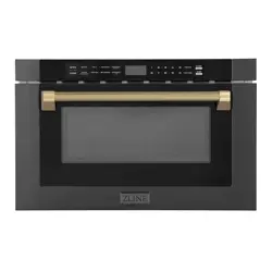
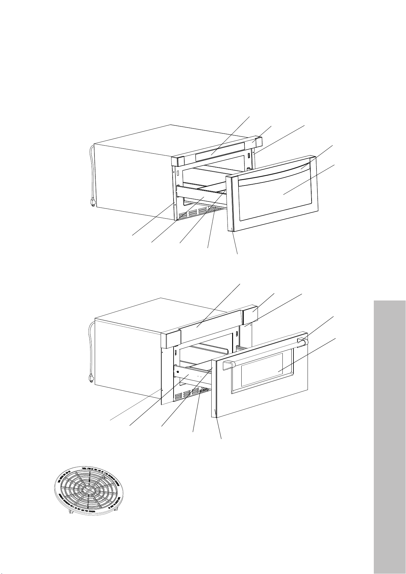
Remove the microwave and all materials from the carton and inside the oven. Your appliance
comes with the following accessories:
5
Touch pad
Control box
Right mounting plate
Handle
Window
Drawer front
Slide rail
Drawer
Drawer
glide
Left
mounting
plate
Cord is
48” (1219 mm)
long
BEFROE
24" Microwaves
SETTING UP YOUR OVEN
Names of Oven Parts and Accessories
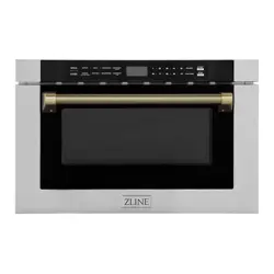
Remove the oven and all materials from the carton and oven cavity.
Your oven comes with the following accessories:
Touch pad
Control box
Right mounting
plate
Handle
Window
Drawer front
Slide rail
Drawer
Drawer
glide
Left
mounting
plate
and do not use for cooking. Do not use without food )
Defrosting Rack( Only be used in defrosting function
8
Cord is
48” (1219 mm)
long
30" Microwaves
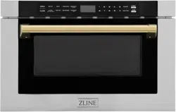
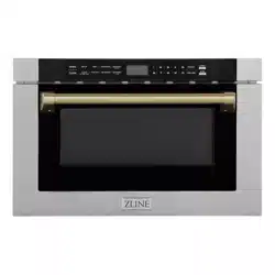
5
Touch pad
Control box
Right mounting plate
Handle
Window
Drawer front
Slide rail
Drawer
Drawer
glide
Left
mounting
plate
Cord is
48” (1219 mm)
long
BEFROE
NOTE: Defrosting Rack should only be used in defrosting function
and not used for cooking. Do not use without food.
Product Specifications
BEFORE INSTALLATION

6
Product Specifications
PRODUCT SPECIFICATIONS
24" 30"
Rated Voltage 120VAC, 60 Hz, 13A 120VAC, 60 Hz, 13A
Rated Input Power 1500W 1500W
Rated Output Power 1000W 1000W
Oven Capacity 1.2 Cu. Ft. 1.2 Cu. Ft.
External Dimensions
(including front panel)
23 1/2" W x 23 5/16" D x 14 7/8" H
(597 mm W x 592 mm D x 378 mm H)
29 3/4" W x 23 3/8" D x 15 3/4" H
(756 mm W x 594 mm D x 400 mm)
External Dimensions
(excluding front panel)
21 7/8" W x 21 3/4" D x 14 3/4" H
(556 mm W x 552 mm D x 375 mm H)
22 1/8" W x 21 3/4" D x 14 3/4" H
(562 mm W x 552 mm D x 375 mm H)
Internal Dimensions
16" W x 16" D x 7” H
(406 mm W x 406 mm D x 178 mm H)
16" W x 16" D x 7" H
(406 mm W x 406 mm D x 178 mm)
Net Weight Approx 70 lb (32 kg) Approx 76 lb (34 kg)
The maximum weight of food placed in the microwave should not exceed 11 lb (5 kg) and
the height should not exceed 5 3/4" (146 mm).
MODEL AND SERIAL NUMBER LOCATION
To locate the model and serial number, open the microwave drawer fully. The label can be
found on the front of the oven, underneath the touch pad.
BEFORE INSTALLATION

7
Electrical Connection
BEFORE INSTALLATION
WARNING
ELECTRICAL CONNECTION
• This appliance must be grounded. In the event of an electrical short circuit, grounding
reduces the risk of electric shock by providing an escape wire for the electric current.
• This appliance is equipped with a cord having a grounding wire with a grounding plug.
The plug must be plugged into an outlet that is properly installed and grounded.
• Improper grounding may result in electrical shock.
• Consult a qualified electrician or service person if the grounding instructions are not
completely understood, or if doubt exists as to whether the appliance is properly
grounded.
• Touching some of the internal components can cause serious personal injury or death.
Do not disassemble this appliance. Do not plug into an outlet until appliance is properly
installed and grounded.
• A short power-supply cord (48"/1219 mm) is provided to reduce the risks resulting from
becoming entangled in or tripping over a longer cord.
• Longer cord sets or extension cords may be used if care is exercised in their use. We do
not recommend using extension cords�
• If a long cord or extension cord is used:
• The marked electrical rating of the cord set or extension cord should be at least as
great as the electrical rating of the appliance.
• Use only a 3-wire extension cord that has a 3-prong grounded plug and 3-slot
receptacle that will accept the plug on the appliance.
• The longer cord should be arranged so that it will not drape over the countertop or
tabletop where it can be pulled on by children or tripped over unintentionally.

8
Installation Notices
BEFORE INSTALLATION
WARNING
CLEARANCES AND DIMENSIONS NOTICE
For safety considerations, do not install the unit in any combustible cabinetry that is not in
accordance with the stated clearances.
UNPACKING YOUR MICROWAVE DRAWER
Remove all packing materials from inside the microwave. DO NOT REMOVE THE
WAVEGUIDE COVER, located on the top of the microwave drawer. Remove the feature
sticker if there is one. Check the unit for any damage, such as misaligned or bent drawer,
damaged drawer seals and sealing surfaces, broken or loose drawer guides, and dents
inside the unit or on the front side of the drawer. If there is any damage, do not operate the
microwave drawer and contact your dealer or ZLINE.
IMPORTANT NOTES TO THE INSTALLER
Read the entire installation portion of the manual before installing the microwave drawer.
Remove all packing materials before connecting the electrical supply. Observe all governing
codes and ordinances. Be sure to leave these instructions with the consumer.
IMPORTANT NOTES TO THE CONSUMER
Keep this manual for the future reference. With use of any heat-generating microwave oven,
there are certain safety precautions you should follow. These are listed in the operation
portion of the manual. Read all and follow carefully. Be sure your microwave drawer is
installed and grounded properly by a qualified installer or service technician.
IMPORTANT SAFETY INSTRUCTIONS
Fire or electrical shock resulting in property damage, personal injury or death may occur
if the information in this manual is not followed exactly. To reduce the risk of tipping, the
microwave drawer must be secured with a properly installed anti-tip block. This unit must
be electrically grounded in accordance with local codes. Make sure any wall coverings
and/or cabinets around the appliance can withstand the heat generated by the microwave
drawer. Never leave the drawer open when the microwave is unattended. Stepping,
leaning, or sitting on the drawer may result in serious injuries and may also cause damage
to the microwave.

9
Installation Cutouts and Clearances
INSTALLATION
INSTALLATION NOTICES
Dimensions shown are precise, and cutout dimensions provide minimum clearances.
• Contact surface must be solid and level. The cabinet floor of the opening should be constructed
of plywood strong enough to support roughly 100 lb (45 kg).
• Microwaves can be built into a cabinet by itself or under a gas or electric wall oven. Clearance
between a wall oven and microwave must be a minimum of 2" (51 mm).
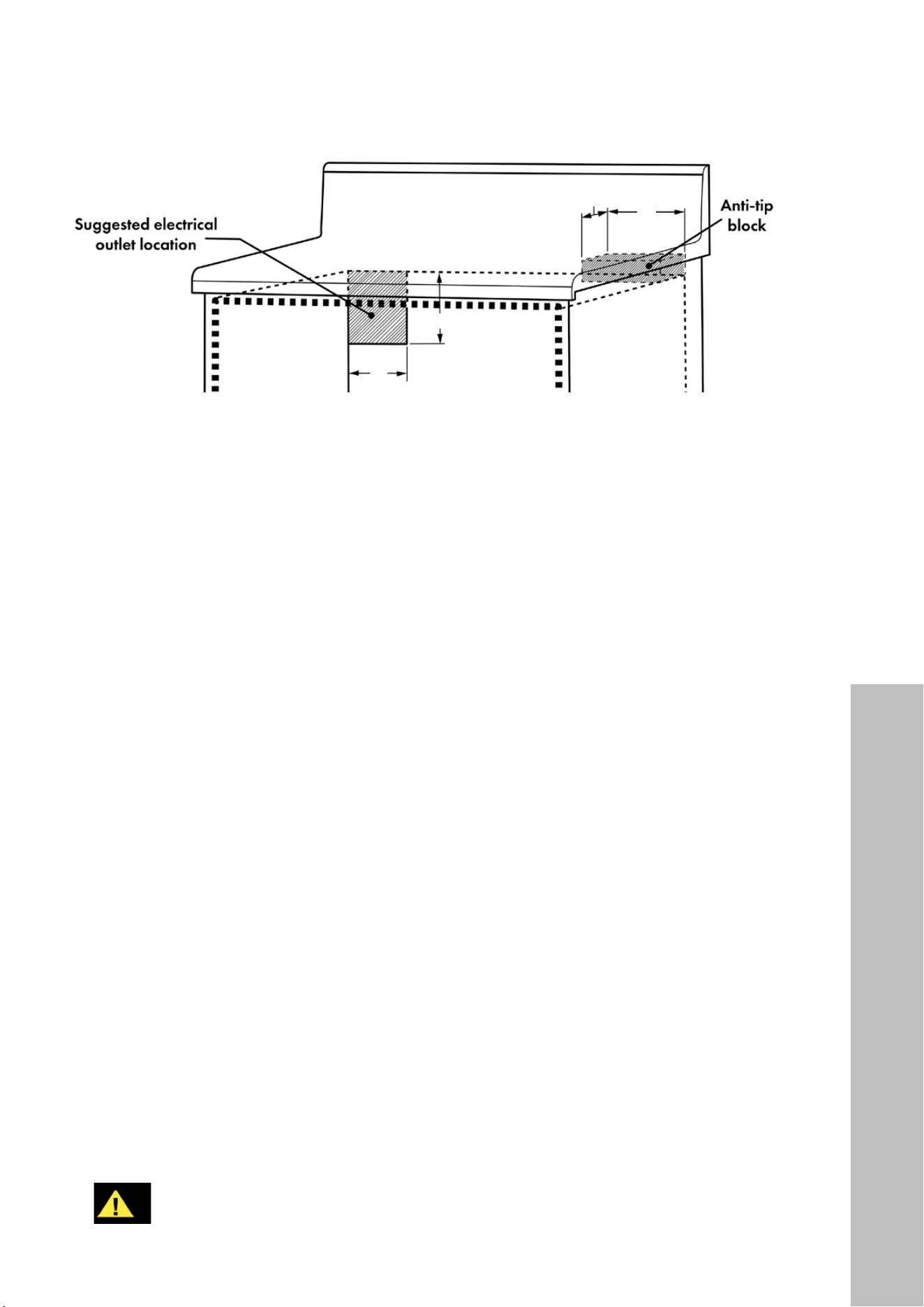
• The recommended electrical outlet location in the shaded area in the upper left-hand corner
of the cabinet (see page 11) is for a flush-mounted outlet.
• The unit can be installed using an electrical outlet behind the cabinet or in an adjacent cabinet
within an area where the provided electrical cord can reach.
• The power cord access hole inside the cabinet should have a minimum diameter of 1 1/2"
(38 mm) and be free of sharp edges. Always allow sufficient power cord length to the
electrical outlet location to prevent tension.
• Always consult a professional installer to confirm cabinet dimensions prior to installing
the microwave, as kitchen layouts vary. This is especially important when installing a 30"
(762 mm) model, as the front panel width (29 3/4", 756 mm) is considerably larger than the
product width itself (22 1/8", 562 mm).
30" Microwaves
24" Microwaves

11
Electrical Outlet & Anti-Tip Block
INSTALLATION
4"
(102 mm)
5" (127 mm)
3 1/2" (89 mm)
6"
(152 mm)
ELECTRICAL OUTLET AND ANTI-TIP BLOCK
• To reduce the risk of tipping the drawer, an anti-tip block must be located a minimum of
15" (381 mm) above the cabinet floor on which the microwave drawer will sit, as outlined
above. A wooden 6" (152 mm) anti-tip block must be provided by the installer. The anti-tip
block prevents serious injury that might result from spilled hot liquids.
• If the drawer is moved to a different location, the anti-tip block must be moved and re-
installed. When secured to the wall, make sure the screws completely penetrate the wall and
are secured in wood or metal so the block is totally stable. When fastening, be sure screws do
not penetrate electrical wiring or plumbing.
• The electrical requirements are 120VAC, 60Hz, 13A. It is recommended that a separate circuit
serving only this appliance be provided.
• The drawer is equipped with a 3-prong grounding plug. Should you only have a 2-prong
outlet, have a qualified electrician install a properly grounded 3-prong outlet.
• The suggested electrical outlet location in the shaded area is for a flush-mounted outlet. The
outlet cannot be located in a surface-mounted box unless additional depth is allowed to
maintain the 23 1/2" (597 mm) cabinet depth as noted on page 10.
• The drawer can be installed using an outlet behind or in an adjacent cabinet. ALWAYS check
if the electrical cord can reach prior to installation.
GROUNDING INSTRUCTIONS
• The microwave drawer must be plugged into a wall receptacle that is properly installed
and grounded in accordance with the National Electrical Code along with local codes and
ordinances. In the event of an electrical short circuit, grounding reduces risk of electrical shock
by providing an escape wire for the electrical current.
WARNING
Improper use of the grounding plug can result in the risk of electric shock� We do not
recommend using an extension cord� If the power supply cord is too short, have a
qualified electrician or service person install an outlet near the appliance�
12
Drawer Installation
INSTALLATION
INSTALLATION THE DRAWER
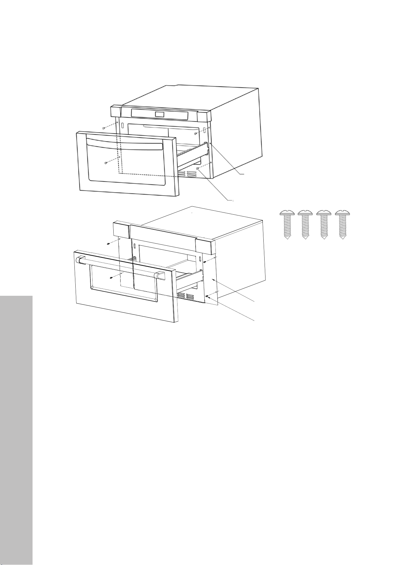
1. Place the drawer near the cabinet opening. Plug the power cord into the electrical outlet.
2. Carefully guide the drawer into the opening. Avoid pinching the power cord.
3. Slide the drawer until the mounting plates are flush with the face of the cabinet.
4. Open the drawer. Using 4 screw holes as a template, pre-drill the cabinet with a 1/16"
bit and secure the drawer with the four screws supplied.
IMPORTANT CABINET CUTOUT NOTES:
• For 30" models, note the difference in width between the front panel (29 3/4",
756 mm) and the product itself (22 1/8", 562 mm). While the minimum cutout
width is 22 3/8" (568 mm), the screw holes to mount the drawer are located on the
edge of the front panel and as such must be secured to the cabinet in this manner.
• For 24" models, note the cutout height (14 3/4", 375 mm) is the same height as
the product itself. This is recommended to ensure a flush installation considering the
front panel height (14 7/8", 378 mm) is only slightly higher. A cutout height of 14
13/16" (376 mm) might be suitable for some installations.
• Always consult a professional installer to confirm dimensions prior to installation.
1. Place the drawer adjacent to the wall or cabinet opening.Plug the power supply cord into the electrical outlet.
2. Carefully guide the drawer into the prepared opening. Avoid pinching the cord between the oven and the wall.
3. Slide the drawer all the way until the mounting
flange is flush with the face of the cabinet.
See Figure 5.
4. Open the drawer. Using the 4 holes on
the drawer as a template , pre drill the cabinet
using a 1/16" bit. See Figure 5.
5. Secure the drawer with the 4 screws supplied.
See Figure 6.
The name plate includes model and serial number. Open the Microwave Drawer fully. The label is beyond the
back wall of the microwave cavity facing up from the flat surface.
Refer to the Operation Manual for cleaning instructions.
4 S c r e ws
4 S c
r e ws
Figure 6
MODEL AND SERIAL NUMBER LOCATION
CARE,CLEANING AND MAINTENANCE
DRAWER INSTALLATION
Figure 5
12
4
DRAWER INSTALL ATION
MODEL & SERIAL NUMBER LOCATION
CARE, CLEANING & MAINTENANCE
Figure 4
Figure 5
1. Place the drawer adjacent to the wall or cabinet opening.
Plug the power supply cord into the electrical outlet.
2. Carefully guide the drawer into the prepared opening.
Avoid pinching the cord between the oven and wall.
3. Slide the drawer all the way until the mounting flange
is flush with the face of the cabinet.
4. Open t
4. Open the drawer. Using the 4 holes on the drawer as
a template, pre-drill the cabinet using a 1/16” bit.
5. Secure the drawer with the 4 screws supplied (Figure 5).
To locate the model and serial number, open the microwave drawer fully. The label can be found beyond
the back wall of the microwave cavity, facing up from the flat surface.
Refer to the Operation Manual for cleaning and care instructions.
30" Microwaves
Mounting screws
Mounting plate
4
DRAWER INSTALL ATION
MODEL & SERIAL NUMBER LOCATION
CARE, CLEANING & MAINTENANCE
Figure 4
Figure 5
1. Place the drawer adjacent to the wall or cabinet opening.
Plug the power supply cord into the electrical outlet.
2. Carefully guide the drawer into the prepared opening.
Avoid pinching the cord between the oven and wall.
3. Slide the drawer all the way until the mounting flange
is flush with the face of the cabinet.
4. Open t
4. Open the drawer. Using the 4 holes on the drawer as
a template, pre-drill the cabinet using a 1/16” bit.
5. Secure the drawer with the 4 screws supplied (Figure 5).
To locate the model and serial number, open the microwave drawer fully. The label can be found beyond
the back wall of the microwave cavity, facing up from the flat surface.
Refer to the Operation Manual for cleaning and care instructions.
24" Microwaves
Mounting plate
Mounting screws

13
HANDLE INSTALLATION
NOTE: The Allen/hex key needed to remove the handle is only included with Autograph
Edition handles (Champagne Bronze, Polished Gold, and Matte Black).
Autograph Edition handles
1. Locate the holes on the underside of each handle base.
2. Using a 7/64" Allen/hex key, turn counter-clockwise to loosen both the left and right
set screws.
3. Carefully remove the handle. If installing an Autograph Edition handle, carefully place
the new handle on the mounting studs. Then, using the Allen/hex key, tighten the left and
right set screws in a clockwise motion until the handle is firmly in place.
Scan to follow along with a video.
Handle Installation
INSTALLATION HANDLES

14
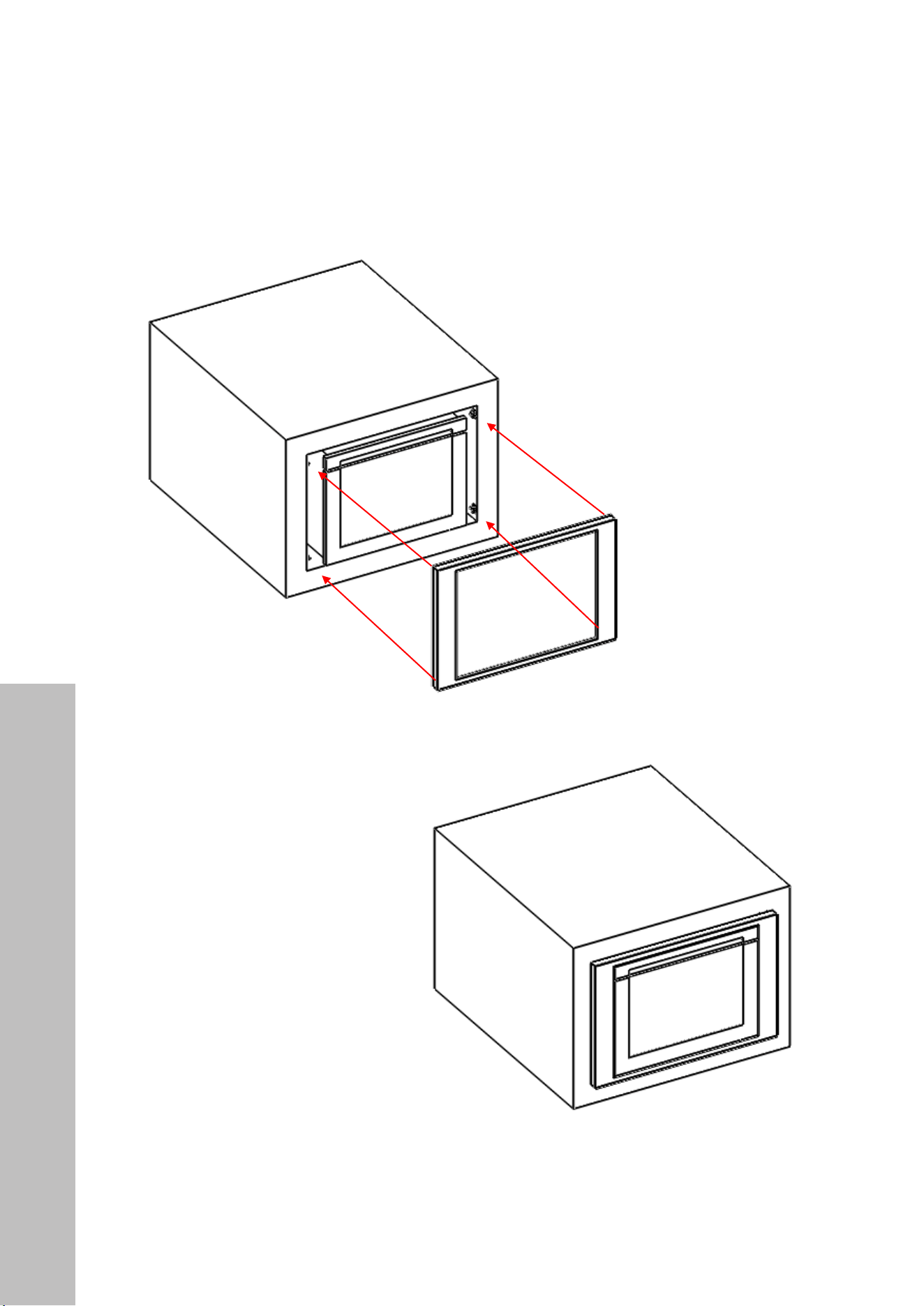
Trim Kit Installation
TRIM KIT INSTALLATION
NOTE: This trim kit is available for purchase as a separate accessory for ZLINE’s 24"
microwave drawer in stainless steel only. The trim kit is only available for the 24" unit; it is
not available in black stainless.
INSTALLATION TRIM KIT
15
Trim Kit Installation
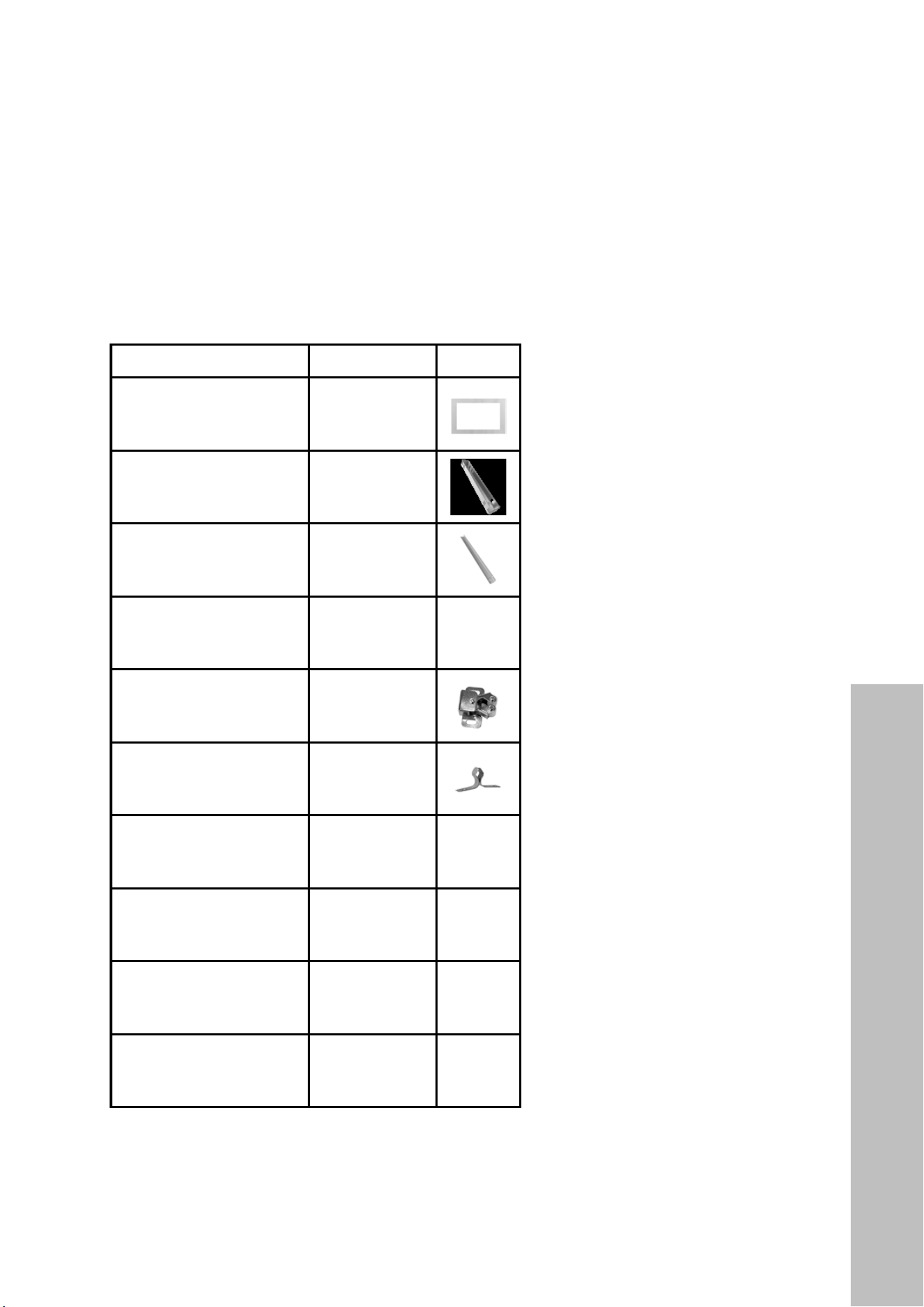
TOOLS NEEDED:
• Phillips-head screwdriver
• Marker
• Drill
PARTS INCLUDED:
PART QUANTITY IMAGE
Outer trim (1) 1
Support beam (2) 2
Front bracket (1) 1
Rear bracket (1) 1
Buckle seat (4) 4
Buckle (4) 4
Finishing washers (4) 4
#1 Screw (4) 4
#2 Screw (16) 16
#3 Screw (2) 2
INSTALLATION TRIM KIT
16
Trim Kit Installation
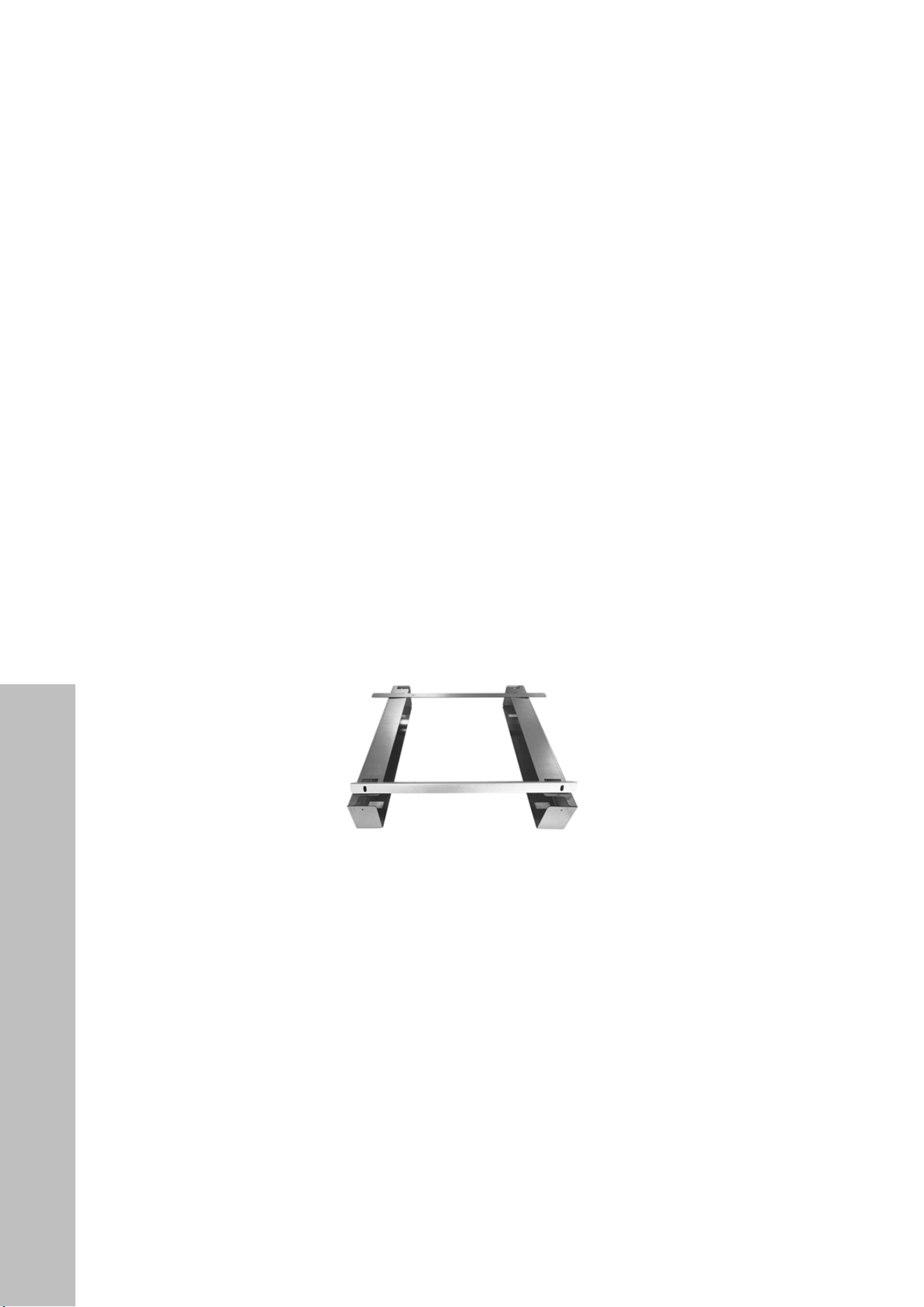
1. Lay the support beams flat on the bottom of the cabinet cutout with the open sides facing
each other (see Figure 1).
Figure 1
Rear bracket
Front bracket
Rear bracket
Front bracket
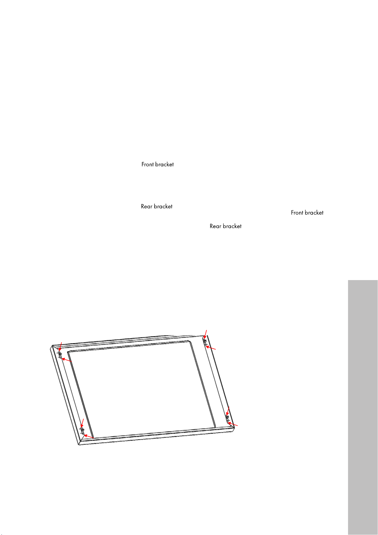
To gauge proper width, temporarily place the rear and front brackets onto the support
beams so the rear bracket lips slide into rear holes on top of the beams and the front
screw holes match to the front of the beams (see Figure 2).
Figure 2
Once aligned, secure the beams by fastening the four #1 screws with washers into the
cabinet base below (see Figure 3).
Figure 3
Rear bracket
Front bracket
Rear bracket
Front bracket
INSTALLATION TRIM KIT
17
Trim Kit Installation
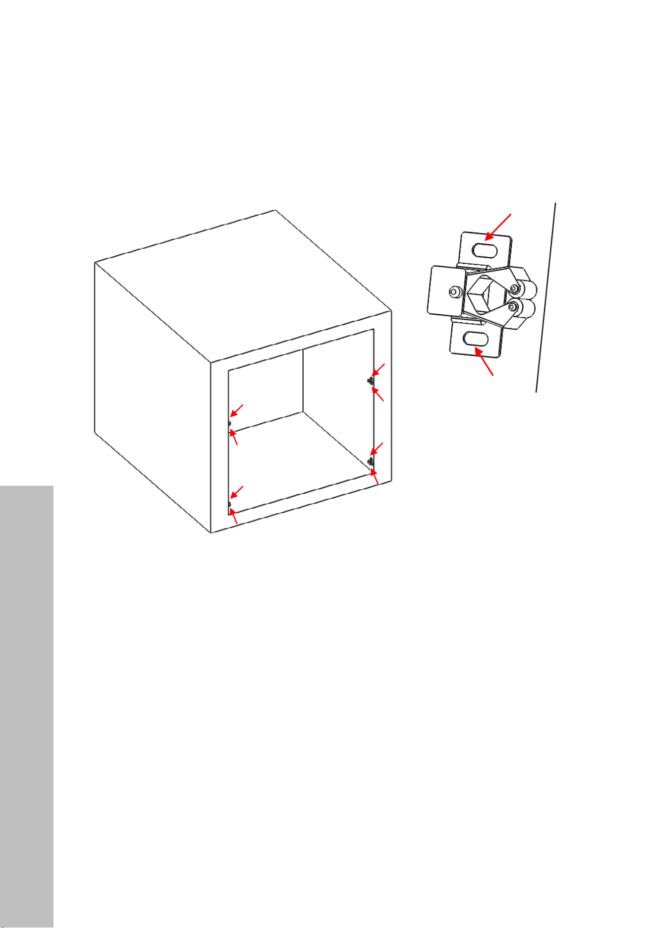
2. Remove the screws from the front bottom of your microwave. Using two of those screws,
secure the front bracket to the bottom of the microwave, ensuring the lip of the bracket is
extending down and facing you. Next, remove the screws from the back bottom of the
microwave and fasten the rear bracket, ensuring the two small lips are extended down
and facing back (see Figures 4 and 5).
Rear bracket
Front bracket
Rear bracket
Front bracket
Rear bracket
Front bracket
Rear bracket
Front bracket
Figure 4
Figure 5
3. Lay the outer trim face down and, using eight of the #2 screws, install the four buckles
on the corresponding mounting holes around the trim kit (see Figure 6). Make sure to use
the same series of mounting holes on each corner, depending on your cabinet cutout
(see Figure 7).
① 将安装好卡扣的外观框放在橱柜上作出比对;用记号笔画上安
装位置
② 用 1#螺丝将卡座安装在对应安装位置上
①
Use 2# screws to install the four buckles on the corresponding mounting
holes around the trim kit 使用 2#螺丝将四个卡扣安装在外观框四周对
应的安装孔上
Place the trim kit which install buckle on the cabinet for
contrast, then use marker strokes to draw the mounting
position
Figure 6
Figure 7
INSTALLATION TRIM KIT
18
4. Next, slide the outer trim into the cabinet cutout and use a marker or pencil to mark
where the buckles line up. Then, remove the trim and secure the four buckle seats into
the cabinet using the other eight #2 screws (see Figure 8). Make sure the clamp of the
bucket seats are facing toward you (see Figure 9).
Figure 8
Figure 9
① 将安装好卡扣的外观框放在橱柜上作出比对;用记号笔画上安
装位置
② 用 1#螺丝将卡座安装在对应安装位置上
①
Use 2# screws to install the four buckles on the corresponding mounting
holes around the trim kit 使用 2#螺丝将四个卡扣安装在外观框四周对
应的安装孔上
Place the trim kit which install buckle on the cabinet for
contrast, then use marker strokes to draw the mounting
position
Trim Kit Installation
INSTALLATION TRIM KIT

19
5. Using two people, lift the microwave and push it into the cabinet until the two small lips
in the rear bracket slide into both holes in the rear of the support beams fastened in Step
1 to the bottom of the cutout (see Figure 10).
6. Use the two #3 screws to fasten the front bracket to the front of both support beams (see
Figure 11). The microwave should now be firmly secured inside the cabinet cutout (see
Figure 12).
Figure 10
Figure 11
Figure 12
Trim Kit Installation
INSTALLATION TRIM KIT
20
Trim Kit Installation
7. Insert the outer trim kit into the cutout (see Figure 13). Clip each buckle onto its
corresponding buckle seat to complete the trim kit installation (see Figure 14).
① Insert the trim kit into the corresponding buckle seat 将
预装好外观框卡进对应卡扣座里
Finish
Figure 13
Figure 14
INSTALLATION TRIM KIT

WARRANTY
COVERAGE
ZLINE Kitchen and Bath microwave parts will be warrantied for two years from the original
purchase date for the original purchaser of the product.
TERMS
This warranty applies only to the original purchaser of the product installed for normal
residential use. This is defined as a single-family, residential dwelling in a non-commercial
setting. Commercial settings include but are not limited to: schools, churches, hotels, restaurants,
vacation rentals such as Airbnb, day care centers, private clubs, fire stations, common areas
in multi-family dwellings, nursing homes, food service locations, and institutional food service
locations such as hospitals or correction facilities. This warranty is non-transferable and will not
be extended based on the date of installation. The warranty applies only to products installed
in the contiguous United States and the District of Columbia. Warranty shall not apply and
ZLINE Kitchen and Bath is not responsible for damage resulting from negligence, improper
maintenance, misuse, abuse, alteration of or tampering with the appliance, accident, natural
disaster, improper electric supply, unauthorized service or repair, improper installation, or
installation not in accordance with the instructions contained in the manual or with the local
government codes..
WHAT IS NOT COVERED
1. Installation or start-up damages or problems caused by improper installation or use.
2. Damage related to unauthorized service or unauthorized parts.
3. Installation in any commercial or non-residential application.
4. Aesthetic damage, scratches, or natural wear caused by normal use.
5. Second-hand, open box products, or products purchased from an unauthorized retailer.
SERVICE
For warranty service, please contact our Customer Service team at
1-614-777-5004 or visit www.zlinekitchen.com/contact to utilize our
online Customer Experience Portal.

WARRANTY
The rating tag shows the model and serial number of your
microwave. The tag is located below the control pad on the
microwave. The tag is visible when the microwave door is
open. Do not remove permanently affixed labels, warnings,
or plates from the product. This will void the warranty.
Need to purchase a part or accessory for your ZLINE product?
Visit ZLINEparts.com, ZLINE's official parts distribution partner.