

INTEGRATED
RS2474BRU Models
INTEGRATED REFRIGERATION
INSTALLATION GUIDE
US CA

3
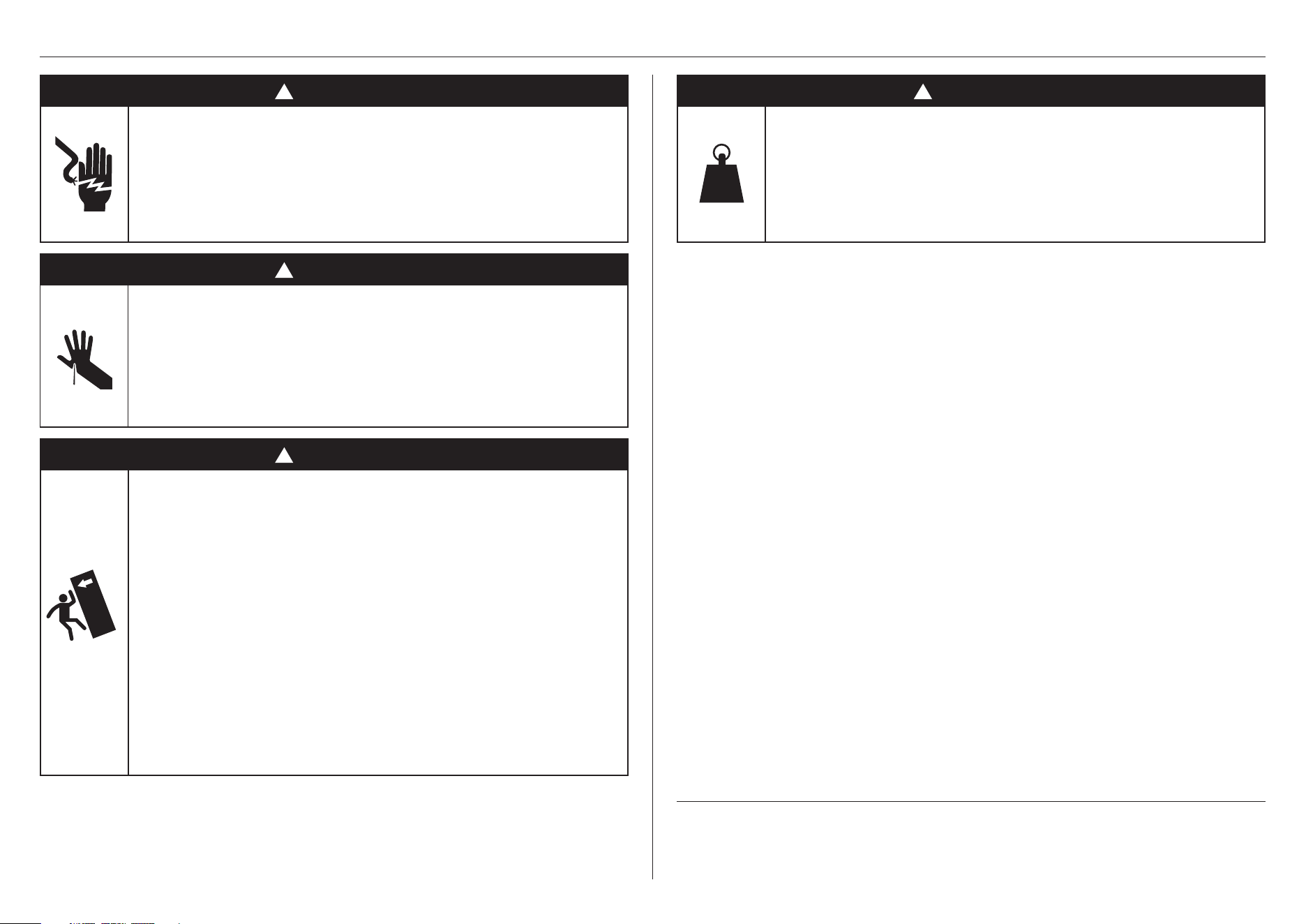
!
WARNING!
Electric Shock Hazard
Failure to follow this advice may result in
electrical shock or death.
• Read and follow the safety and warnings before
operating this appliance.
!
WARNING!
Sharp Edge and Pinch Point Hazard
Failure to follow this advice may result
in injury.
• Take care: panel edges may be sharp.
• Do not put fingers in the drawers when closing.
!
WARNING!
Tip Hazard
Failure to follow this advice may result in
damage or personalinjury.
• This product may tip up until it is fully installed.
Keep children away and take care.
• This appliance is top-heavy and must be secured
to prevent the possibility of tippingforward.
To ensure that the appliance is stable under all
loading conditions:
• Theanti-tip bracket and fittings supplied must
be installed by a professional installer according
tothe installation steps in this guide.
SAFETY AND WARNINGS
!
WARNING!
Weight Hazard
Failure to follow this advice may result in
damage or personalinjury.
• The appliance is heavy. Please ensure adequate
care is taken when installing the appliance.
READ AND SAVE THIS GUIDE
WARNING!
To avoid hazard, follow these instructions carefully before Installing or using thisappliance.
z
Please make this information available to the persons installing the appliance.
z
Assume all electrical parts are live.
z
Disconnect power supply before servicing and installation.
SAVE THESE INSTRUCTIONS
The models shown in this installation guide may not be available in all markets and are subject to
change at any time. For current details about model and specification availability in your country,
please go to our website www.fisherpaykel.com or contact your local Fisher&Paykel dealer.

4
PRIOR TO INSTALLATION INSTALLATION MILESTONES
DURING INSTALLATION
z
The appliance has front and rear rollers to easily move forward and backward. Do not move
the appliance sideways to avoid damaging the rollers or the floor covering/surface.
z
Ensure your appliance is not exposed to any heat generating appliance eg cooktop, oven
or dishwasher.
z
The appliance must be installed by a qualified installer, or Fisher and Paykel trained and
supported service technician to avoid faulty electrical and plumbing connections.
z
All connections for electrical power and grounding must comply with local codes and
ordinances and be made by licensed personnel when required.
z
All plumbing meeting local codes also required.
z
Avoid installation of the appliance/s under a ground fault circuit interrupter (GFCI).
z
Ensure the appliance is installed properly. Improper installation that results in appliance
failure is not covered under the appliance warranty.
ELECTRICAL/PLUMBING
z
Electrical and water supply connections for these appliances can be located in an
adjacent area or unit (cabinet or cupboard) that is easily accessible in case of repair or
disconnection.
z
Ensure an isolating switch is available if electrical connection is not accessible.
z
Ensure an isolation valve is available if water connection is not accessible.
z
Contact an electrical and/or a plumbing professional if you are uncertain the electrical and/
or plumbing conditions for installation.
z
Ensure the door of the appliance is closed when rolling into thecabinetry.
z
For flush installation, ensure the door panels are installed flush with cabinetry front surface.
Ensure appliance is properly centred.
z
Ensure floor is protected to prevent damage.
z
All four corners of the appliance must be supported firmly on the floor to eliminate any
movement. Installing the appliance on a soft, uneven, or not level floor may cause twisting
and poor door sealing.
z
Use low speed, low torque setting when using a powered driver for the screws when fixing
or aligning the product.
These milestones represent areas throughout
that are pivotal to an optimal installation
outcome. These steps require additional
installer attention and should be quality
checked once completed.
Check anti-tip bracket is correctly installed.
Remove cap from valve before connecting the hose and tightening.
Connect to services and check for leaks.
Push into alcove. Ensure depth gauges touch the alcove front.
Adjust product height. Ensure all feet engage with the floor and the upper bracket
touches the alcove.
Expand spacers. Ensure no gaps are present.
Milestone indicator
MILESTONE LINKS
Recheck all gaps and any clashing.
Installer checklist.
5
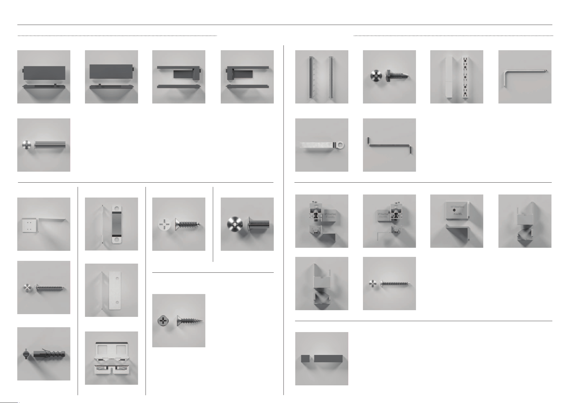
PARTS REQUIRED
INSTALLATION KIT (INTERNAL BOX)
Trim UI RS24 non Hinge
RH
Screw ST 8X5/8 CSK PH
AB ZP
Twinthread screw 8GX19
Screw SD #7X13 PAN
PH ZP
Cap divider flow door
Depth gauge non hinge
Blocker air bypass
kickstrip
Bolt limiting hinge K08
Screw MC M5X12 MSH
PH ZP
Screw hinge spacer
Install kit H - UI Trim kit
Anti-tip bracket
Screw WS #10X35 T17
WFR PH ZP
Plug masonry
SP630#10X30MM
Install kit A -
Bracket anti tip assy
Miscellaneous parts
Ball hex key M4
Install kit D - Kit flow divider
Trim UI RS24 Hinge LHTrim UI RS24 non hinge
LH
Trim UI RS24 Hinge RH
Assy hinge spacer A Cover hinge spacer A
Install kit B - Kit hinge spacer & depth gauges
Assy hinge spacer B
Cover hinge spacer B
Door seal flow divider
Spanner door
L key combi PH2 T25
Install kit C -
Kit door screw
Slider bracket skin DR
60cm
Bracket trim side door
24”
Install kit F -
Kit panel attach
Spacer bracket side DR
60cm
Install kit G - Kit screw
panel attachment
Install kit E - Kit screw
alcove attachment
6
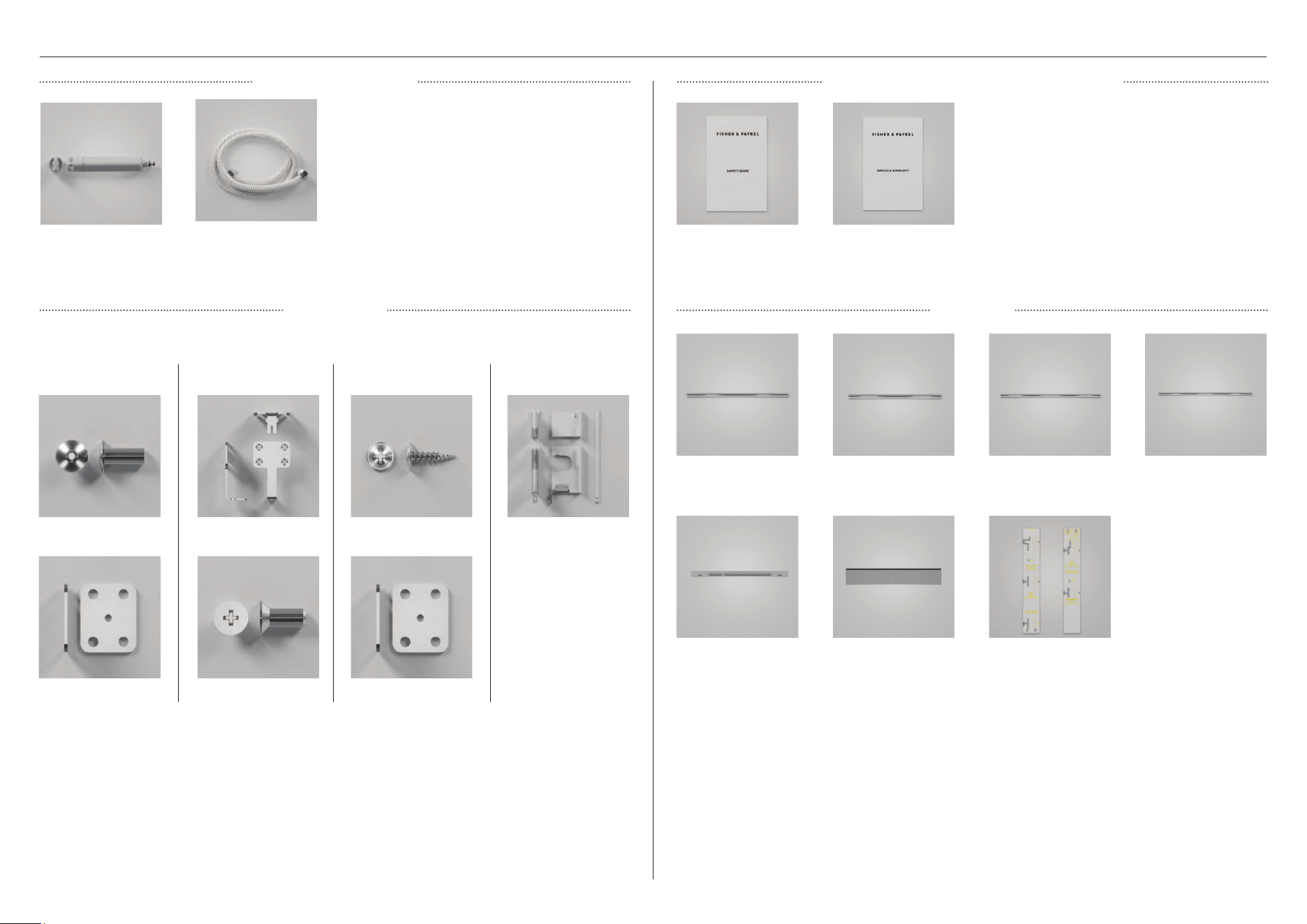
PARTS REQUIRED
WATER FILTER KIT
JOINER KIT
MISCELLANEOUS ITEMS (MI) PACK
Water filter
(comes fitted to product)
TRIM KIT
EXTRUSION PANEL
DOOR B TOP 24”
EXTRUSION PANEL
DOOR B BTM 24”
TRIM TOP DOOR 24”
TRIM SIDE HINGE DR B
BTM 24”
MTG PALTE TOE KICK
RS24
Safety booklet Service and Warranty
TRIM SIDE HINGE DR B
TOP 24”
Template Panel Door
B 24”
Bracket dual connection
top
Screw M5X12 CSKPH NPBracket duel plinth FNT
(x2)
Screw M5X12 PH MT
STL ZN
Screw 8GX16 mush
washer HD
Trim centre dual install
24”
To be ordered seperately for multiple installation.
Joiner kit A
bracket joiner plinth
Joiner kit B
bracket joiner top
Joiner kit C
bracket joiner rear
Bracket duel plinth FNT
Miscellaneous
Braided hose, 7/16” x 24
UNS
7
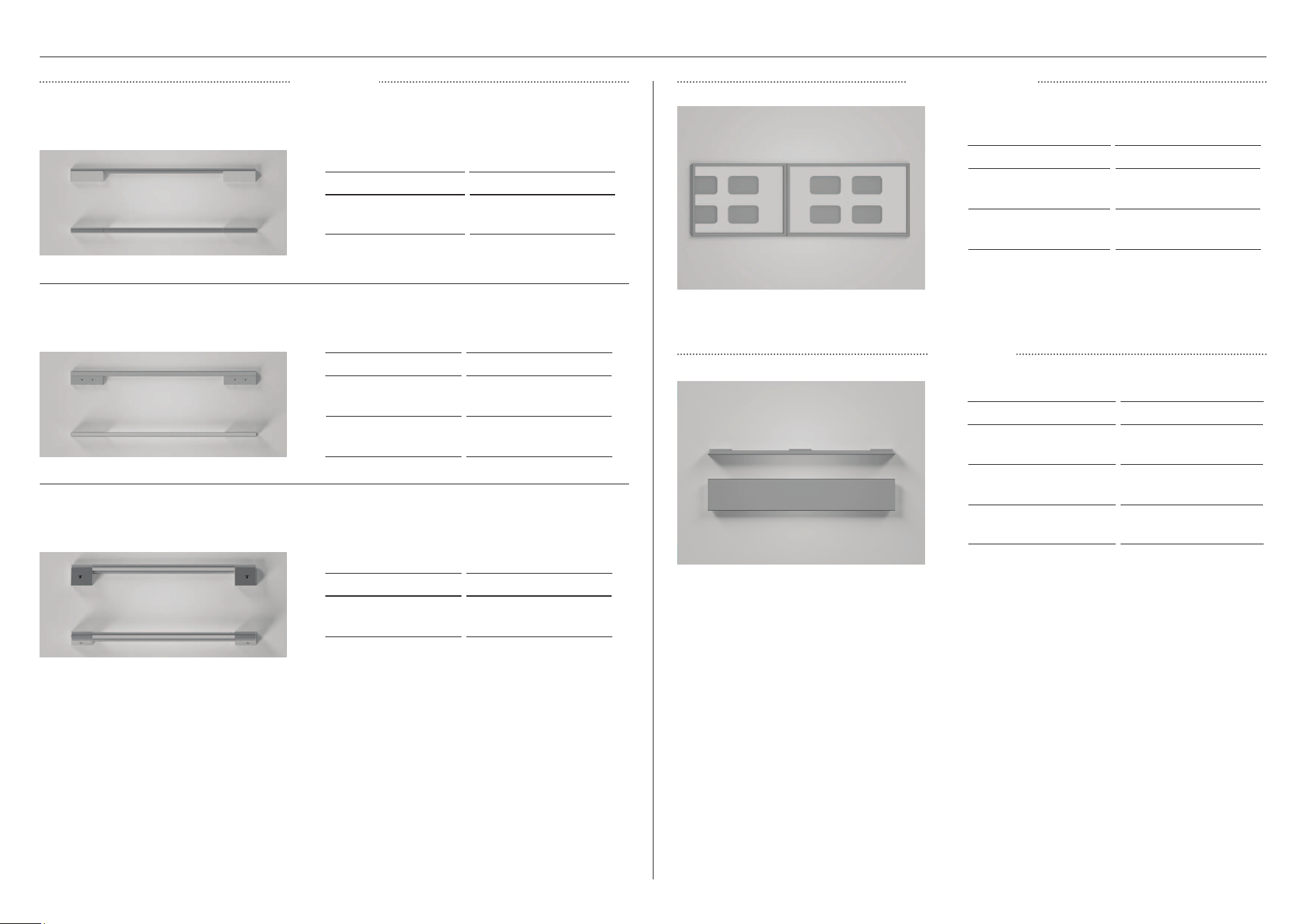
OPTIONAL ACCESSORIES
DOOR PANELSHANDLES
Round handle (2) M5x25 Hex screw (4)
Square fine handle (2) M5x25 Hex screw (4)
Round flush handle (2) M5x25 Hex screw (4)
MODEL DESCRIPTION
AHSRDB19 Round Handle Kit
Round handle set
Square Fine handle set
Professional round flush handle set
MODEL DESCRIPTION
AHD5RDB19 Square fine handle
kit SS
AHD5RDB19B Square fine handle
kit BLK
MODEL DESCRIPTION
AHP3RDB19 Professional round
flush handle kit
MODEL DESCRIPTION
RD6019BR Right hinge door
panel kit
RD6019BL Left hinge door
panel kit
TOE KICK
MODEL DESCRIPTION
AKRS06010 Single install toe kick
AKRS12010 Dual install toe kick
AKRS18010 Triple install toe kick
8
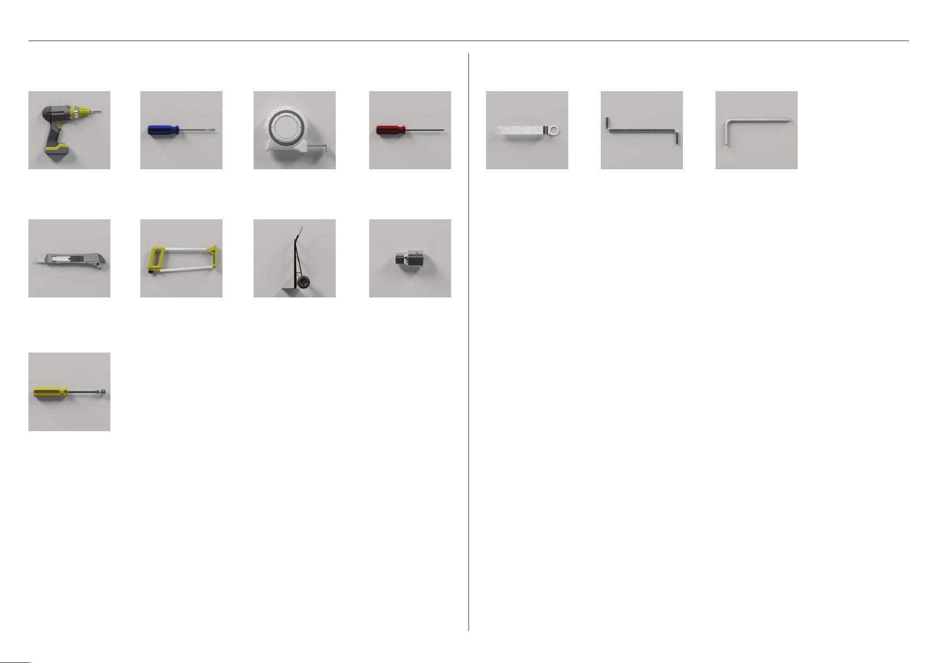
TOOLS REQUIRED
L key combi
PH2 T25
Spanner
Supplied toolsRequired tools
Not supplied and must be provided by the installer.
M4 Ball allen key
Powered driver
Hand truck
Cross-head
screwdriver
Flathead screwdriver
Cutter
Socket 8mm
Measuring tape
Hacksaw
Nut driver
9
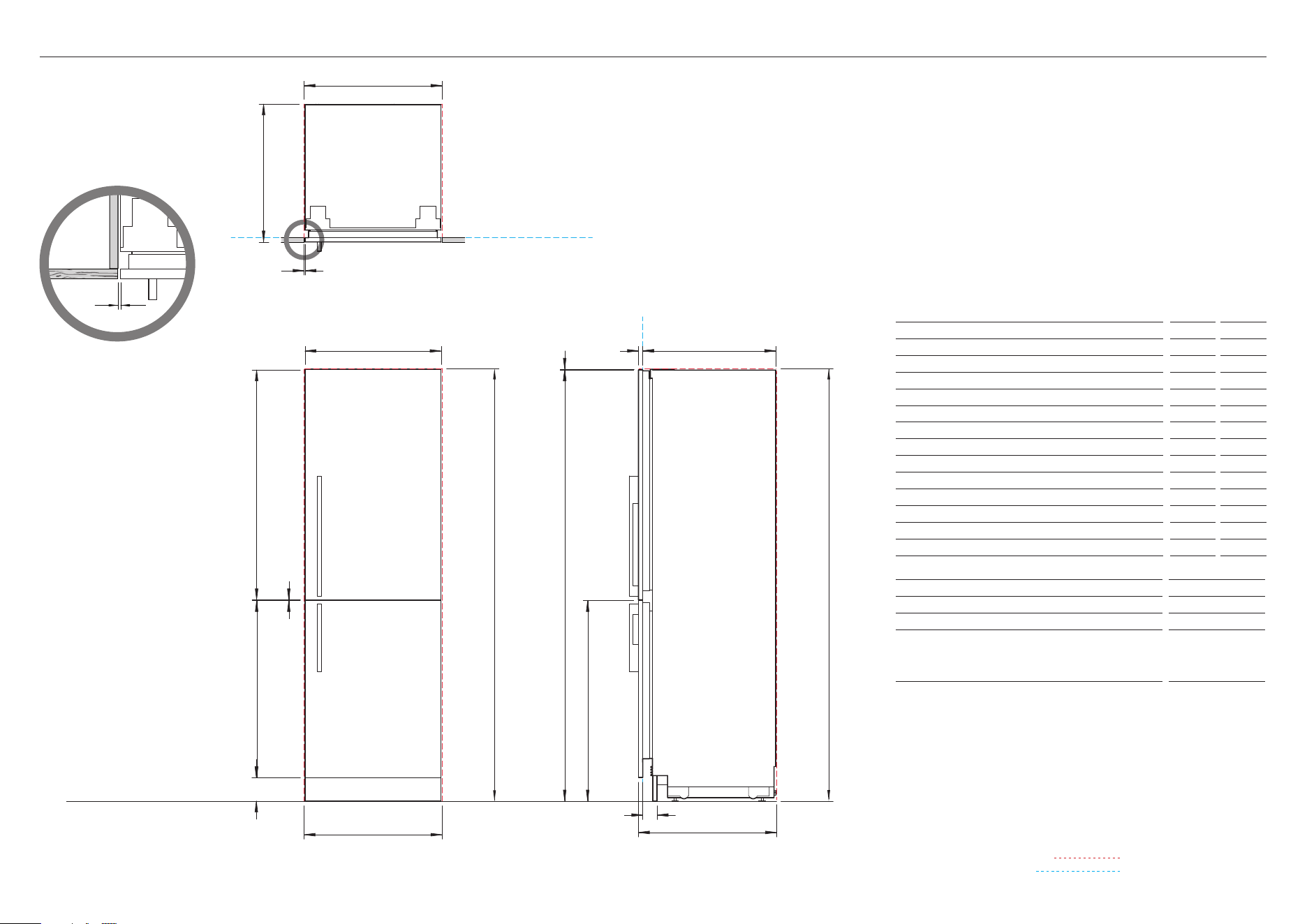
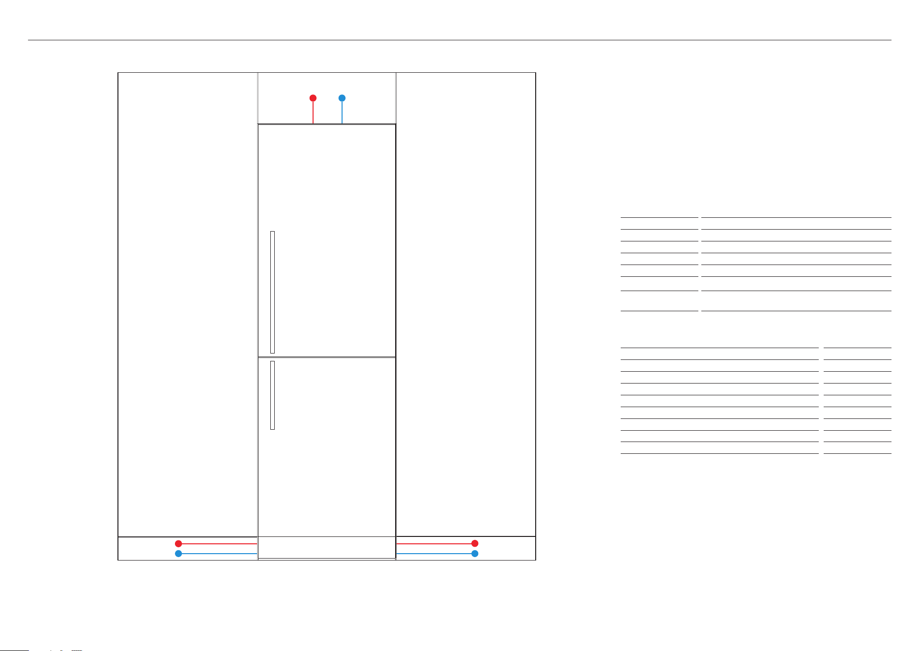
PRODUCT AND CAVITY DIMENSIONS
RS2474BRU1 with Stainless Steel Panels RD2474BR, Handle Kit AHD5RDS74B and
Stainless Steel Toe Kick Panel AKRS2304
Left hand hinge is a mirrored version of the image shown. Left hand hinge can be
achieved using supplied parts.
RS2474BRU1 with Stainless Steel Panels RD2474BL, Handle Kit
AHD5RDS74B and Stainless Steel Toe Kick Panel AKRS2304
Product Dimensions
in
mm
a Overall height of product
74
1880
B Overall width of product
23 5/16
592
C Overall depth of product (excl. front door panels)
22 13/16
579
D Height from top of top door panel to floor
7 3 7/ 8
1877
E Height from top of bottom door panel to floor
34 3/8
873
F Minimum cabinetry clearance from side of door panel
5/32
4
G Minimum cabinetry clearance from top of door panel
1/8
3
H Height of top door panel
39 13/32
1001
I Height of bottom door panel
30 3/8
771
J Depth of door panels
3/4
19
K Gap between door panels
1/8
3
L Height from floor to bottom of bottom door panel
4
102
M Depth of toe kick (excl. front door and toe kick panels)
2 – 4
50 – 100
Cavity Dimensions
in
mm
N Overall height of cavity
74
1880
O Overall width of cavity
23 5/8
600
P Minimum overall depth of cavity:
• When services are located outside of cavity (shallow)
• When services are located in the cabinet above the cavity
• When services are located at rear of cavity (deep)
23 5/8
24
25 9/16
600
610
650
Note: Product shown installed on the floor. Slide into cabinetry position. Alternatively
can be installed on a plinth. Adjust your cavity height accordingly.
Dimensions may vary by ± 1/16’’ (2mm)
O
P
F
B
G
C
A
H
O
N
E
PLAN VIEW
FRONT VIEW
P
PROFILE VIEW
INDICATES CAVITY CLEARANCES
INDICATES PRODUCT DATUM
DATUM: FRONT OF CHASSIS
DATUM:
FRONT OF CHASSIS
K
I
L
D
J
M
FLOOR
VERTICAL GAP
CLEARANCE FROM SIDE
OF DOOR PANEL
5/32"
10
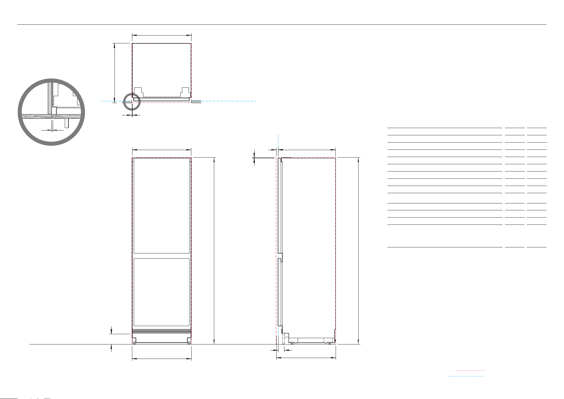
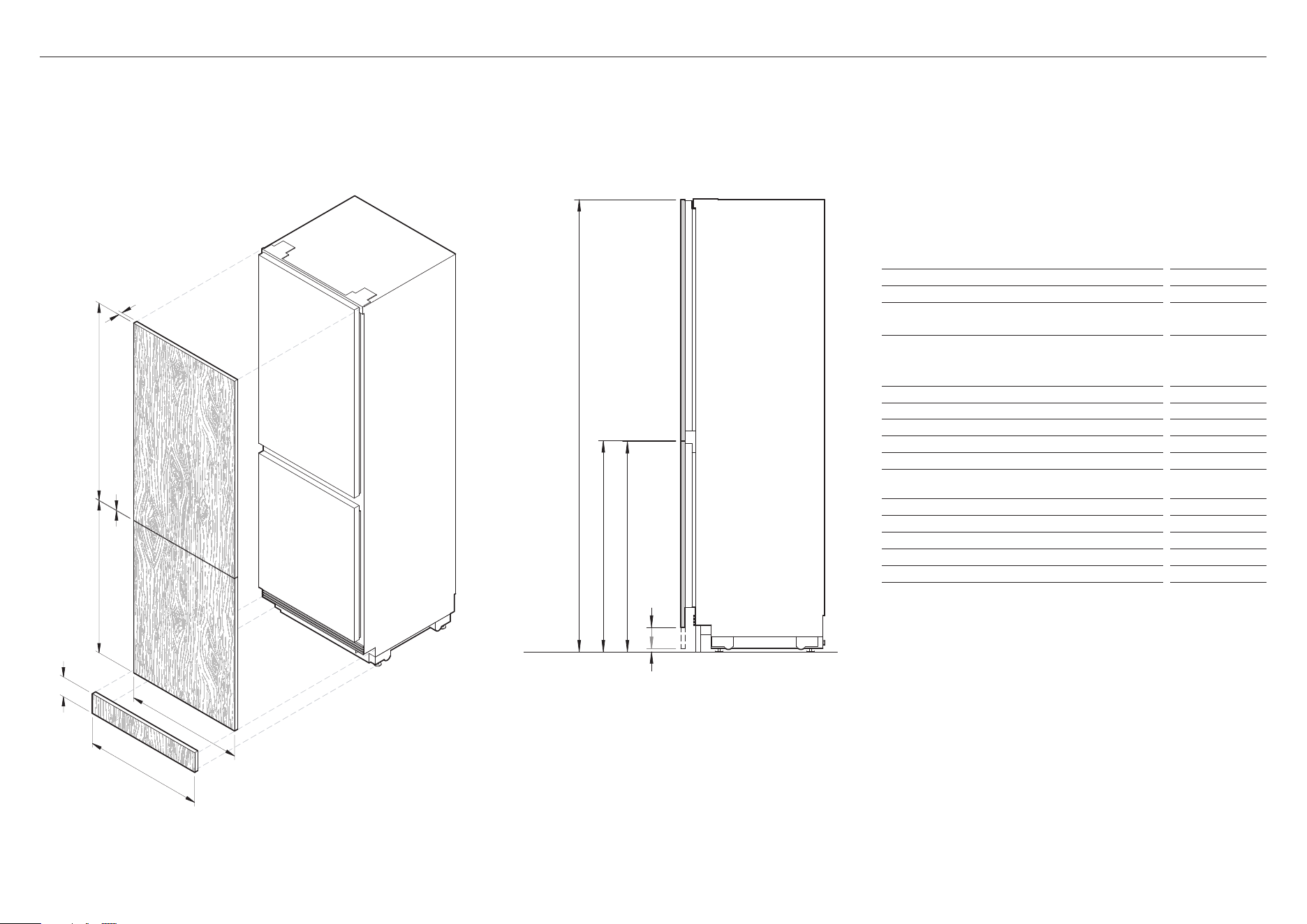
PRODUCT AND CAVITY DIMENSIONS
O
INDICATES CAVITY CLEARANCES
INDICATES PRODUCT DATUM
K
D
C
A
J
FRONT VIEW
K
PROFILE VIEW
DATUM: FRONT OF CHASSIS
G
F
H
FLOOR
E
B
PLAN VIEW
DATUM:
FRONT OF CHASSIS
I
NOTE: Left hand hinge is a mirrored version of the image shown.
Left hand hinge can be achieved using supplied parts.
Product Dimensions in
mm
a Overall height of product
74
1880
B Overall width of product
23 5/16
592
C Overall depth of product
22 13/16
579
D Minimum cabinetry clearance from side of door panels*
5/32
4
E Minimum cabinetry clearance from top of door panel*
1/8
3
F Depth of door panels*
5/8 – 3/4
16 – 19
G Height of toe kick panel*
4
100
H Depth of toe kick (excl. front door and toe kick panels*)
2 – 4
50 – 100
Cavity Dimensions
in
mm
I Overall height of cavity
74
1880
J Overall width of cavity
23 5/8
600
K Minimum overall depth of cavity:
• When services are located outside of cavity (shallow)
• When services are located in the cabinet above the cavity
• When services are located at rear of cavity (deep)
23 5/8
24
25 9/16
600
610
650
Note: Product shown installed on the floor. Slide into cabinetry position. Alternatively
can be installed on a plinth. Adjust your cavity height accordingly.
For custom panel dimensions refer to page 13
* Custom door panels and toe kick panel to be manufactured and fitted
by cabinetmaker.
Dimensions may vary by ± 1/16’’ (2mm)
VERTICAL GAP
CLEARANCE FROM SIDE
OF DOOR PANEL
5/32"
11
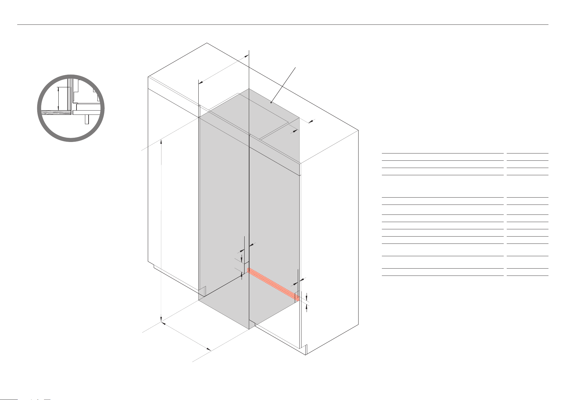
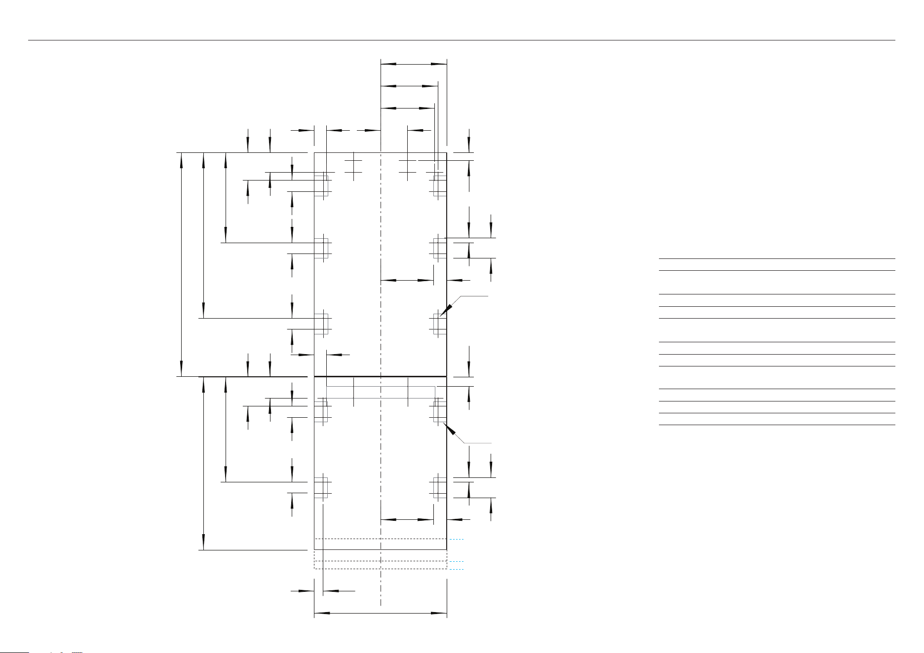
CAVITY PREPARATION
NOTE: Left hand hinge is a mirrored version of the image shown.
For ease of installation, ensure cavity has consistent dimensions top to bottom and left
to right.
Minimum Cavity Dimensions
in
mm
a Overall height of cavity
74
1880
B Overall width of cavity
23 5/8
600
c Minimum overall depth of cavity:
• When services are located outside of cavity (shallow)
• When services are located in the cabinet above the cavity
• When services are located at rear of cavity (deep)
23 5/8
24
25 9/16
600
610
650
Minimum required finished return
4
100
Electrical / Plumbing Supply Dimensions
in
mm
d Overall height of supply routing area at rear of cavity
1 7/16
37
Overall width of supply routing area at rear of cavity
23 5/8
600
E Overall depth of supply routing area at rear of cavity
13/16
20
F Height of notch at rear of cavity for services to be routed into
adjacent cabinet (either side)
4
100
G Depth of notch at rear of cavity for services to be routed into
adjacent cabinet (either side)
2 3/16
55
H Minimum depth above cavity for services to be routed through
2 3/16
55
Recommended that services are routed to the adjacent cabinet or either side of
the product.
Dimensions may vary by ± 1/16’’ (2mm)
ALTERNATIVE AREA
ABOVE CAVITY FOR
ELEC / WATER CONNECTION
B
C
A
D
E
ISO VIEW
G
F
H
FINISHED RETURN
CAVITY SIDES & TOP
4"
12
SERVICES
LEFT HAND SIDE RIGHT HAND SIDE
A
D
B
E
C F
FRONT VIEW
Specifications
Electrical
Supply
115 VAC, 60 Hz
Service
10 amp circuit
Plumbing
Supply
Braided hose, 7/16” x 24 UNS
Pressure
min 40 psi (150 kPa)
max 120 psi (827 kPa) @ 68°F (20°C)
NOTE: Recommended that services are routed to the adjacent cabinet.
Hose and Cord Lengths
in
mm
Electrical
a Power cord length (from the left edge of the product)*
74
1800
B Power cord length (from the right edge of the product)*
78 3/4
2000
C Power cord length (from the top of the product)*
14 15/16
380
Water
D Water inlet hose length (from the left edge of the product)
96 7/16
2450
E Water inlet hose length (from the right edge of the product)
78 3/4
2000
F Water inlet hose length (from the top of the product)
27 9/16
700
* Excluding plug.
13
CUSTOM PANEL DIMENSIONS
NOTE: Left hand hinge is a mirrored version of the image shown.
Left hand hinge can be achieved using supplied parts.
Custom Panel Dimensions
in
mm
a Height of top door panel
39 13/32
1001
B Height of bottom door panel
28 7/16
– 33 3/4
723 – 858
C Width of door panel:
• Single install
• Dual install*
• Triple install*
23 5/16
23 3/8
23 13/32
592
594
594.5
D Depth of custom panel**
5/8 – 3/4
16 – 19
E Gap between door panels
5/32
3
F Height from floor to top of top door panel
7 3 7/ 8
1877
G Height from floor to bottom of top door panel
34 1/2
876
H Height from floor to top of bottom door panel
34 3/8
873
I Height from floor to bottom of bottom door panel***
9/16
– 5 15/16
15 – 150
J Height of toe kick panel
4
100
K Width of toe kick panel****
23 1/2
597
Maximum weight of top door panel*****
21lbs
9.5kg
Maximum weight of bottom door panel*****
20lbs
9kg
Custom door panels, handles and toe kick panel to be manufactured and fitted
by cabinetmaker.
* For further details on multiple installation refer to the planning guide
** At 3/4” (19mm) thickness, we recommend an edge radius of 1/16” (1mm) or more to
avoid the possibility of panel clash when opening
*** The grille becomes visible at heights over 100mm
**** Can be continuous
***** Includes weight of handle
PROFILE VIEWISO VIEW
A
B
C
D
E
F
G H
I
J
K
FLOOR
14
CUSTOM PANEL PREPARATION
Custom Panel Preparation
Dimensions are shown in inches (in).
Dimensions apply for the preparation and installation of custom panels
Handles
Ensure handle screw heads are countersunk into back of panel to avoid
interfering with hanging bracket, and clear of side brackets as indicated.
Dwg & Dxf Files
Dwg and Dxf files of the panel preparation can be downloaded from Trade
Resources www.fisherpaykel.com
Template
A template for marking and drilling the holes is provided with the product
REAR VIEW
Do not place handle holes in
these locations
Ø2.5mm 3/32"
Pilot holes only
Do not penetrate front surface
For 5 15/16" make 2" shorter
BREAKLINE
FROM FLOOR TO BOTTOM OF PANEL
For 2" make 2" longer"
For 9/16" make 3 11/32" longer
10 1/16
11 5/8
25/32
3 17/32
39 13/32
TOP PANEL
BOTTOM PANEL
25/32
3 17/32
2 3/8
1 5/8
2 1/8
1 31/32
1 31/32
1 31/32
1 31/32
1 31/32
2 1/8
4 3/4
9 1/2
1 13/32
3 7/16
4 15/16
15 7/8
29 1/8
3 11/165 1/8
18 7/16
30 7/16
1 9/16
23 5/16
9 9/32
2 3/89 9/32
15
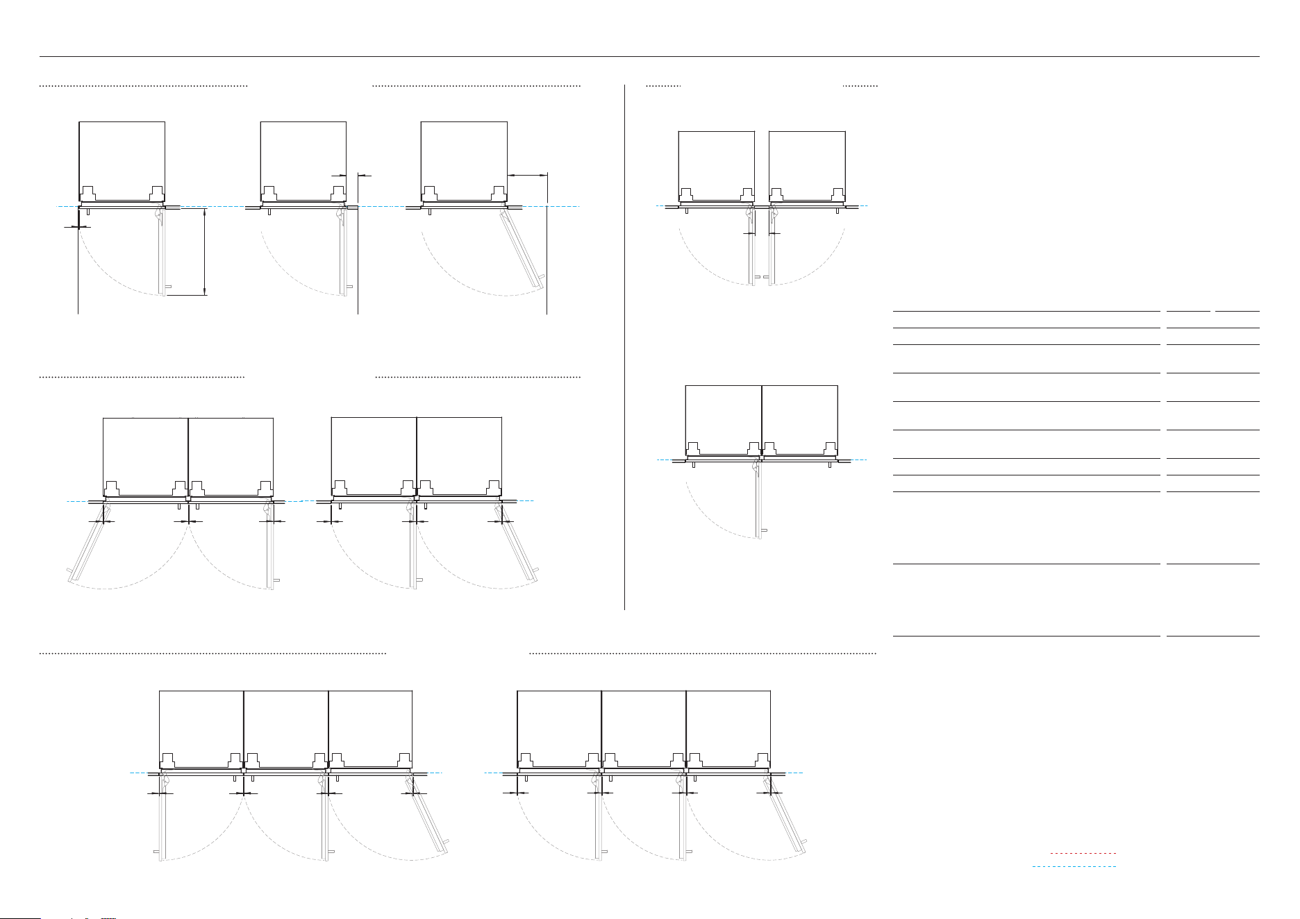
DOOR CLEARANCES
D
A
B
WALL
WALLWALL
C
FF F FF F
GG G GG GG G
E
HINGE TO HINGE
Both doors open at the same time
- requires space between models
HINGE TO HINGE
Only allows a single door open at a time
INDICATES CAVITY CLEARANCES
INDICATES PRODUCT DATUM
CLEARANCES CONFIGURATIONS
DUAL INSTALL
TRIPLE INSTALL
RS2474BRU1 with Stainless Steel Panels RD2474BR, Handle Kit AHD5RDS74B and
Stainless Steel Toe Kick Panel AKRS2304
Left hand hinge is a mirrored version of the image shown. Left hand hinge can be
achieved using supplied parts.
RS2474BRU1 with Stainless Steel Panels RD2474BL, Handle Kit
AHD5RDS74B and Stainless Steel Toe Kick Panel AKRS2304
Clearance Dimensions
in
mm
a Depth of door (90° open, measured from front of cabinetry)
23 5/8
600
B Minimum door clearance to adjacent wall (90° – reduced
internal access)* **
3 1/8
80
C Minimum door clearance to adjacent wall (115° – full
internal access)* **
10 3/4
273
D Minimum cabinetry clearance from side of door panel to
adjacent wall (non hinge side)
5/32
4
E Minimum clearance between products when opening hinge
to hinge. Allowing both doors to open at the same time**
4
100
Minimum Door Clearance (Vertical Gap)
in
mm
F Dual Install:
•
Stainless steel door panels (gaps equalized
during installation)
3/16
5
•
Custom panels (width of custom panel increased to
maintain 4mm gap across multiple products)***
5/32
4
G Triple Install:
•
Stainless steel door panels (gaps equalized
during installation)
1/4
6
•
Custom panels (width of custom panel increased to
maintain 4mm gap across multiple products)***
5/32
4
* Use hinge limiting pin to restrict door opening to 90° where necessary
** Minimum dimensions shown are for the contemporary handle kit AHD5RDSF.
Custom panel and handle details need to be taken into account.
*** Refer to Custom Panel Dimensions and Multiple Install pages for further details.
16
PRIOR TO INSTALLATION
Check alcove is square and is secured to
the wall. Ensure front of alcove is square
to the top of the alcove and the floor
is flat.
Measure alcove dimensions. Ensure all
minimum specs have been met.
If alcove depth is greater than 24”
(610mm), a spacer will need to be
installed alongside the anti-tip bracket.
Refer to page 18 for details.
Ensure a finished return has been created.
1
2
3
4
Ensure services are accessible and
correctly installed. Refer to ‘services’
for details.
Ensure all bracket and handle holes have
been pre-drilled. Refer to ‘custom panel
preparation’ for details.
Ensure all door and toe kick panels
are square and set up to the correct
specifications. Refer to ‘custom panel
preparation’ for details.
1
2
CHECK CAVITY CHECK PANELS
17
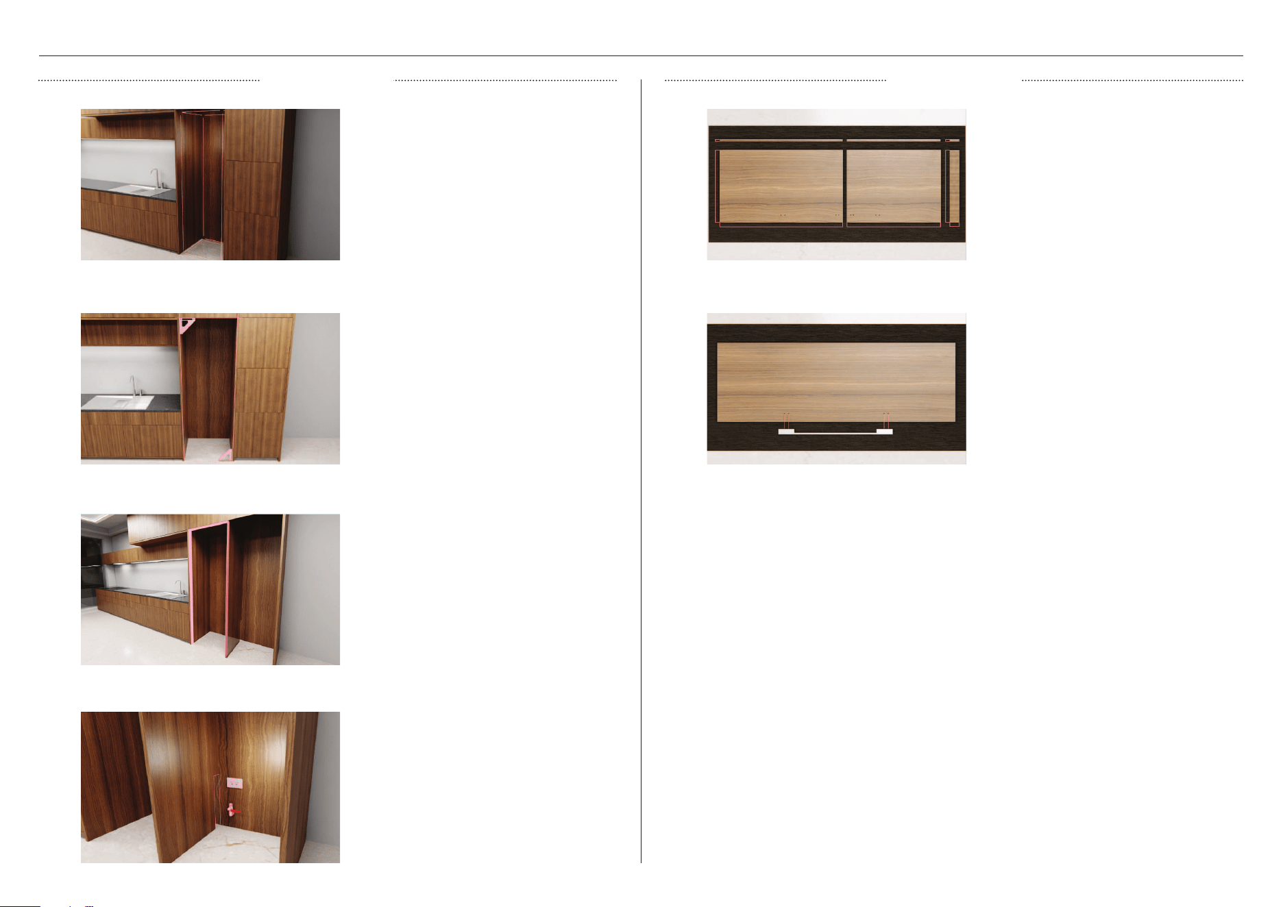
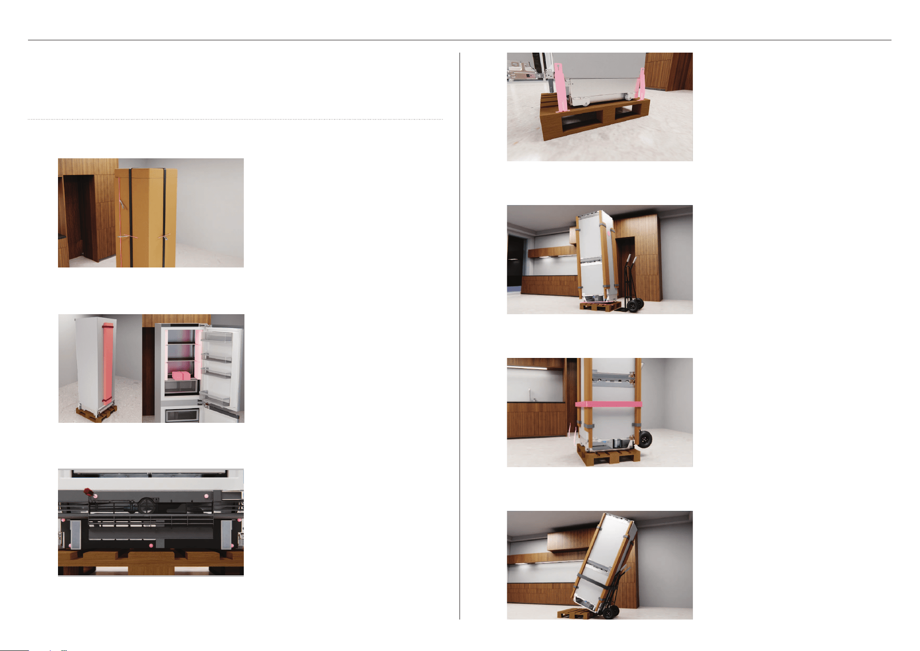
UNPACK PRODUCT
Remove all pre packaged parts and set
aside. Do not discard.
Cut straps, lift the top cap off and cut
down the side of the carton to remove.
Dispose of packaging responsibly.
Push the grille flap to open and unscrew
the two screws behind the flap and five
on the grille. Set screws aside. Open the
door and pull the grille outwards from
the product.
1
2
3
z
Keep all packing materials until the unit has been inspected.
z
Inspect the product to ensure there is no shipping damage. If any damage is detected
contact the dealer or retailer you bought the product from to report the damage.
z
Fisher & Paykel is not responsible for shipping damage.
Tilt product onto handtruck and
remove palette. Move product to the
installation location.
Remove and discard corner posts.
7
Remove the two remaining
transit brackets.
6
4
Using a crosshead screwdriver, unscrew
the transit brackets from one side of the
product and set aside.
Check levelling feet have been raised,
tilt product and insert handtruck.
Restrain product to handtruck.
We recommend using the corner
posts to protect the product when
using restraints.
5
18
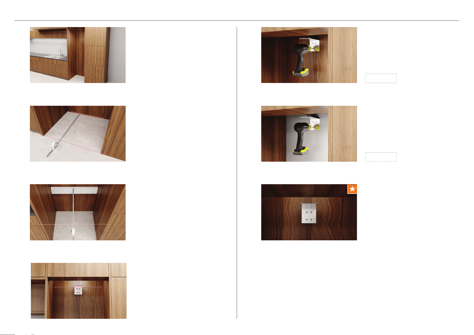
INSTALL ANTI-TIP BRACKET
Measure the height from floor to the
front overhang and mark on rear wall.
4
If required, install a spacer at the rear of
the cavity to bring depth to 24” (610mm).
3
7
Ensure that the anti-tip bracket is
installed correctly to prevent the
possibility of the appliance tipping
forward when the door is opened.
Check for wall stud.
1
For solid wall installs:
Using the bracket as a guide, pre-
drill four holes into the wall or spacer.
Secure bracket using crosshead screws.
5
Install kit A
Measure the depth range of the alcove
ensuring the minimum depth range has
been met.
2
6
For masonry wall installs:
Using the bracket as a guide, pre-drill
four holes into the wall. Hammer four
masonry plugs into the wall until flush
before securing the bracket using
crosshead screws.
Install kit A
19
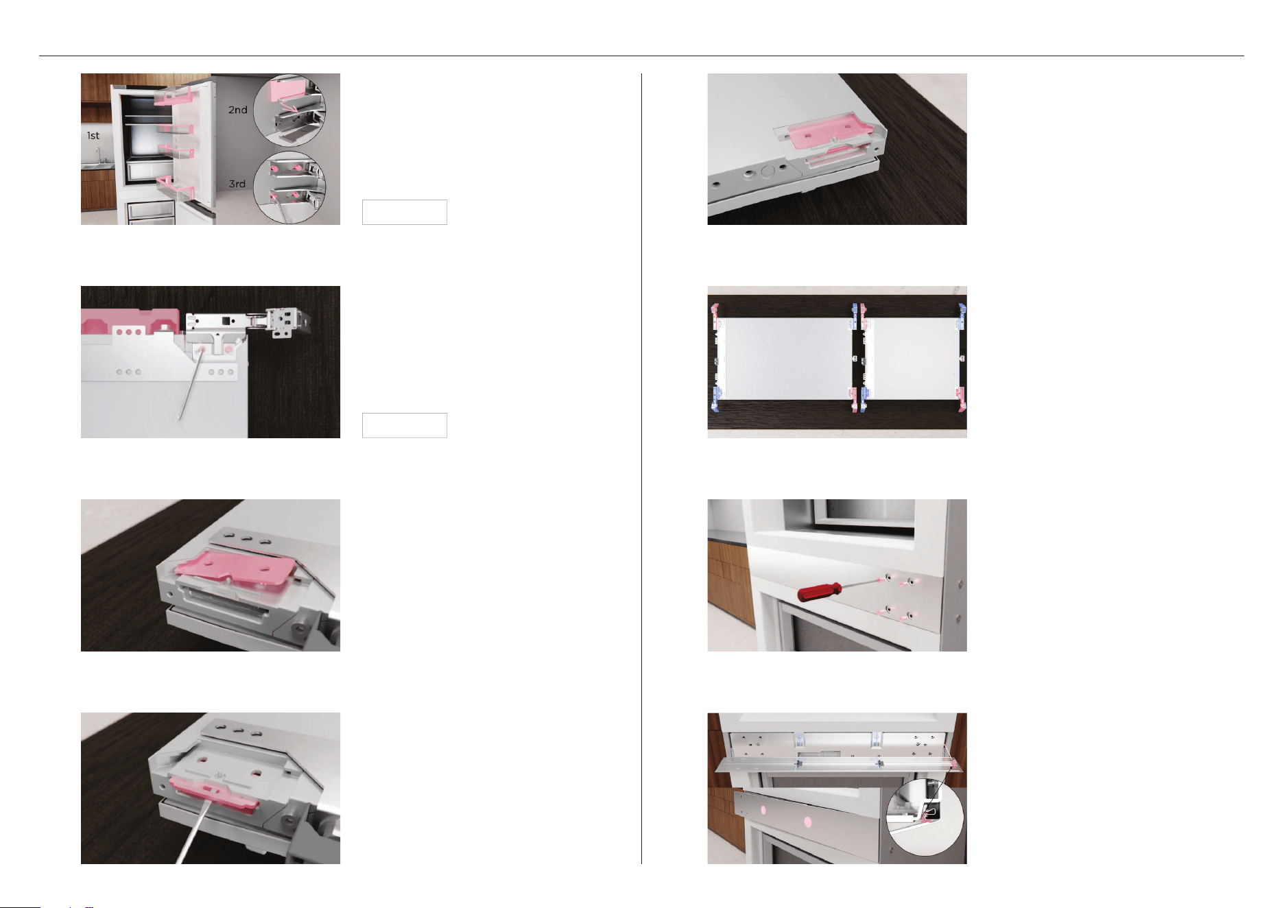
HINGE SWAP (OPTIONAL)
2
Swap hinges as illustrated. Ensure
base of hinge is parallel and
tightened securely.
Refit top covers.
6
Carefully remove hinges from door and
set aside.
Remove both top covers and set aside.
Install kit D
4
Use a flathead screwdriver to remove
the inside plates. Move to the other
side ensuring the rounded corners face
the inside.
8
Ensure the 2x centre clips are on
its marks and the side hooking clip
on place.
Locate trim by hooking clip then
applying pressure to each centre clip
position until clipping sound is heard.
Push on the edge of the outside plates,
lift out and swap to the other side.
3
7
Remove all 4 screws shown. Pull the
trim out from hinge edge and flip 180°.
1 5
Check plates are positioned correctly.
Open the door and remove the door
shelves. Unclip hinge covers from
middle hinges. Loosen the hinge
screws using the supplied Torx T25
driver. Slide the door out and place
onto a protected surface.
Install kit D
20
JOIN PRODUCTS (MULTIPLE PRODUCT INSTALLS ONLY)HINGE SWAP (OPTIONAL)
Secure the bracket at the front base
using four screws.
2
!0
Swap alcove bracket with the hinge
bracket. Secure using 3 screws at the
top of the cabinet.
Joiner kit A
Secure the bracket at the rear base
using four screws.
!2
Refit both centre hinge covers by
aligning to the hinge as shown, and
sliding across to clip back hinge covers
into position.
Joiner kit A
3
4
!1
Slot the door back onto the screws
and tighten using a torx key to tightly
secure. Refit the door shelves.
Repeat steps for lower door.
Secure the bracket at the front top
using four screws.
Joiner kit B
19
Partially refit the 4x hinge screws.
Secure the bracket at the rear top
using four screws.
Joiner kit C

21
Repeat process for additional products.
5
JOIN PRODUCTS (MULTIPLE PRODUCT INSTALLS ONLY) DEPTH GAUGES & SPACER
Using the supplied crosshead screws,
fit the depth gauges at the the top &
bottom of the door as shown.
Multiple product installs:
Fit either the depth gauges or spacers
at the top and bottom of the product
based on your installation as shown.
INSERT HINGE LIMITING PIN (OPTIONAL)
To limit the door opening to 90⁰, place
the hinge limiting pin into the lower
hinges on both doors.
1
2
3
Install kits B & C
Clip both hinge spacers onto
the product.
Ensure spacer
A is fitted to the top of
the product and spacer B is fitted to the
bottom of the product, for right-hand
hinge installations and vice versa for
left-hand hinge installations.
1
Install kit B
Install kit H
22
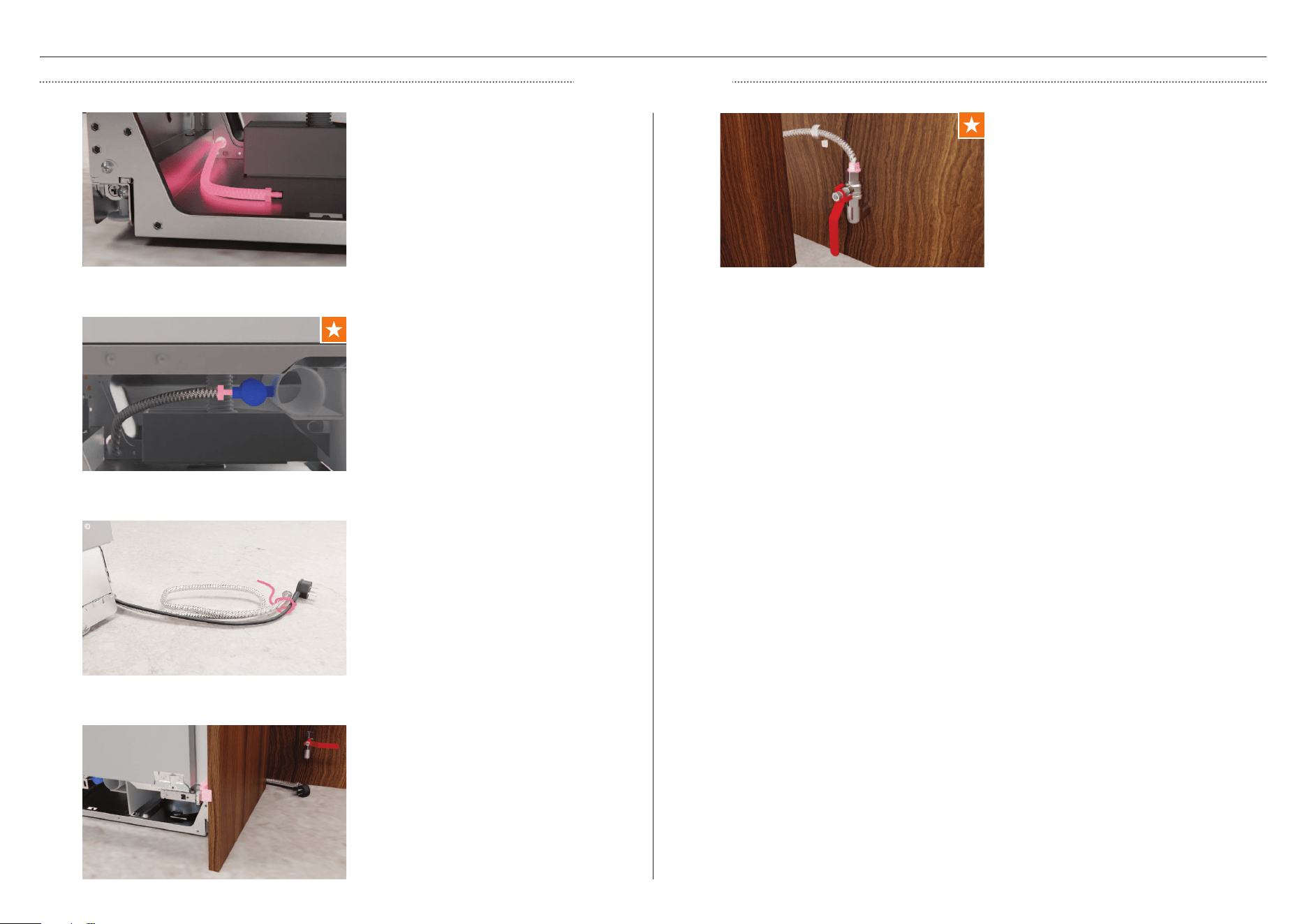
3
If required, wrap a thread around the
hose and power cord to bring any slack
inside the plinth and reduce the risk of
them tangling behind the product.
Push product into alcove while pulling
the hose and power cord. Ensure the
gauges touch the alcove end, the
hose doesn’t kink and the power cord
remains free and untangled.
4
OUTSIDE ALCOVE
SERVICE CONNECTIONS
Route the hose from rear of product
through to front corner.
1
5
Connect to tap and turn on. If water is
running, check for leaks.
Connect to outlet and turn power on.
Remove the cap from the valve before
connecting the hose and tighten.
2
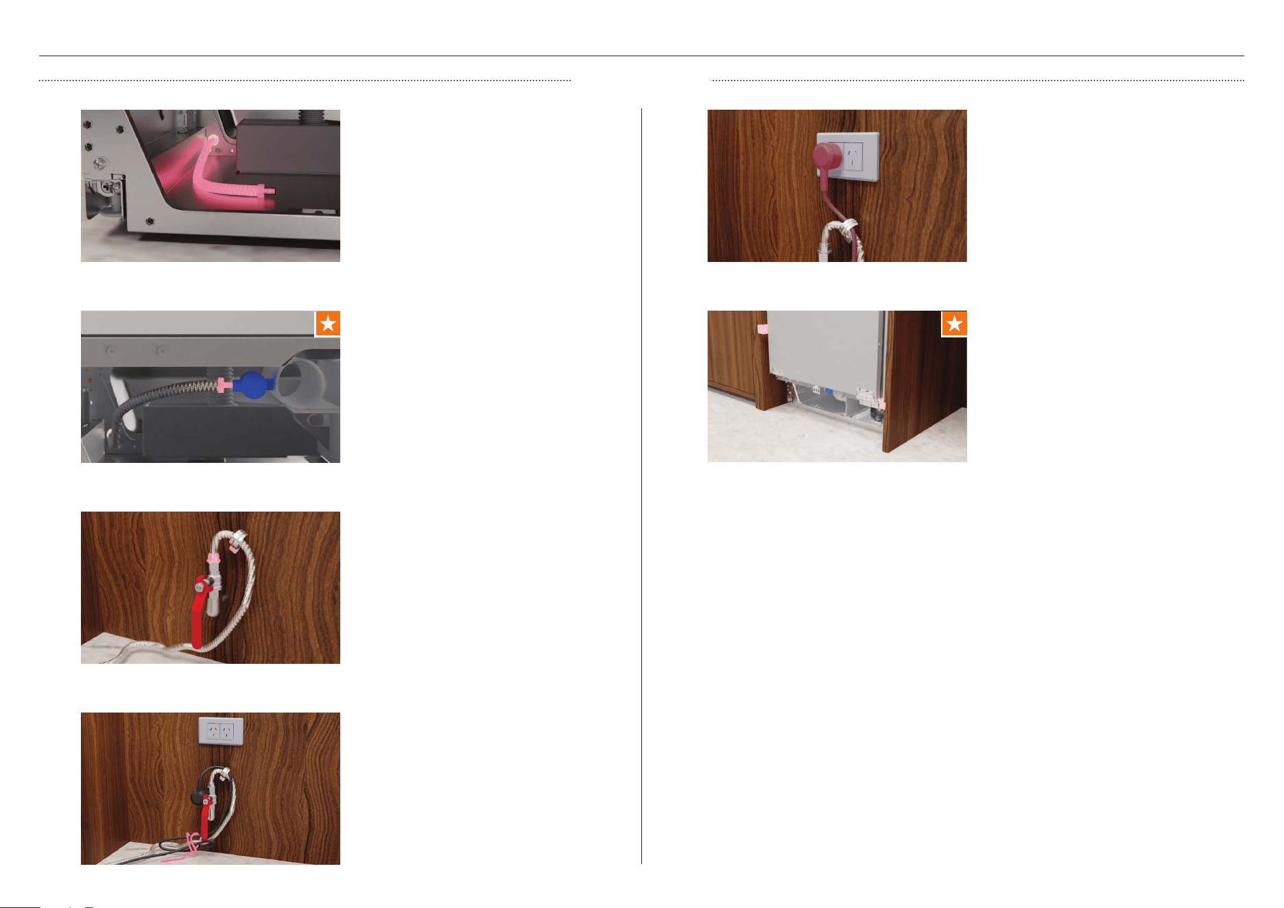
23
If required, wrap a thread around the
hose and power cord to bring any slack
inside the plinth and reduce the risk of
them tangling behind the product.
4
INSIDE ALCOVE
SERVICE CONNECTIONS
5
Connect to outlet and turn power on.
Route the hose from rear of product
through to front corner.
1
3
Connect to tap and turn on. If water is
running, check for leaks.
Push product into alcove. Push in until
the gauges touch the alcove end. Ensure
hose doesn’t bend or kink and that the
power cord is not trapped.
6
Remove the cap from the valve before
connecting the hose and tighten.
2
24
ADJUST HEIGHT IN CAVITY
*assuming panel thickness of 3/4” 19mm.
Multiple product installs:
Beginning with the outside feet, turn the
righthand screw to adjust the rear of the
product followed by the lefthand screw
to adjust the front. Once product is set
in cavity, adjust the central feet.
Ensure feet engage with the floor and
the upper bracket touches the alcove.
2
Snap the ends off both spacers.
2
SECURE PRODUCT
1
Turn the righthand screw to adjust the
rear of the product followed by the
lefthand screw to adjust the front. Turn
clockwise to raise and anti-clockwise
to lower.
Ensure feet engage with the floor and
the upper bracket touches the alcove.
1
Profile view - alcove alignment
Front adjustment
Front view
Rear adjustment
Open the door and secure following
the sequence shown. The longer screws
should be used where shown in blue, and
the smaller screws where shown in red.
Ensure a gap between drill and product
is maintained to avoid cosmetic damage.
Install kit B & E
4
Open the door and use the supplied hex
key to expand the spacers. Ensure no
gaps are present.
4
Unscrew the crosshead screws to
remove depth gauges. Set aside.
Install kit D
3
Clip covers onto spacers.
Ensure cover A is fitted to spacer A and
cover B to spacer B.
3
Install kit B
Plan view
Ensure all depth gauges are flush to the
front of the alcove.
Where this is not possible:
Measure the distance between the
chassis front and the alcove front as
shown, ensuring it is 2 7/16” (62mm)*.
25
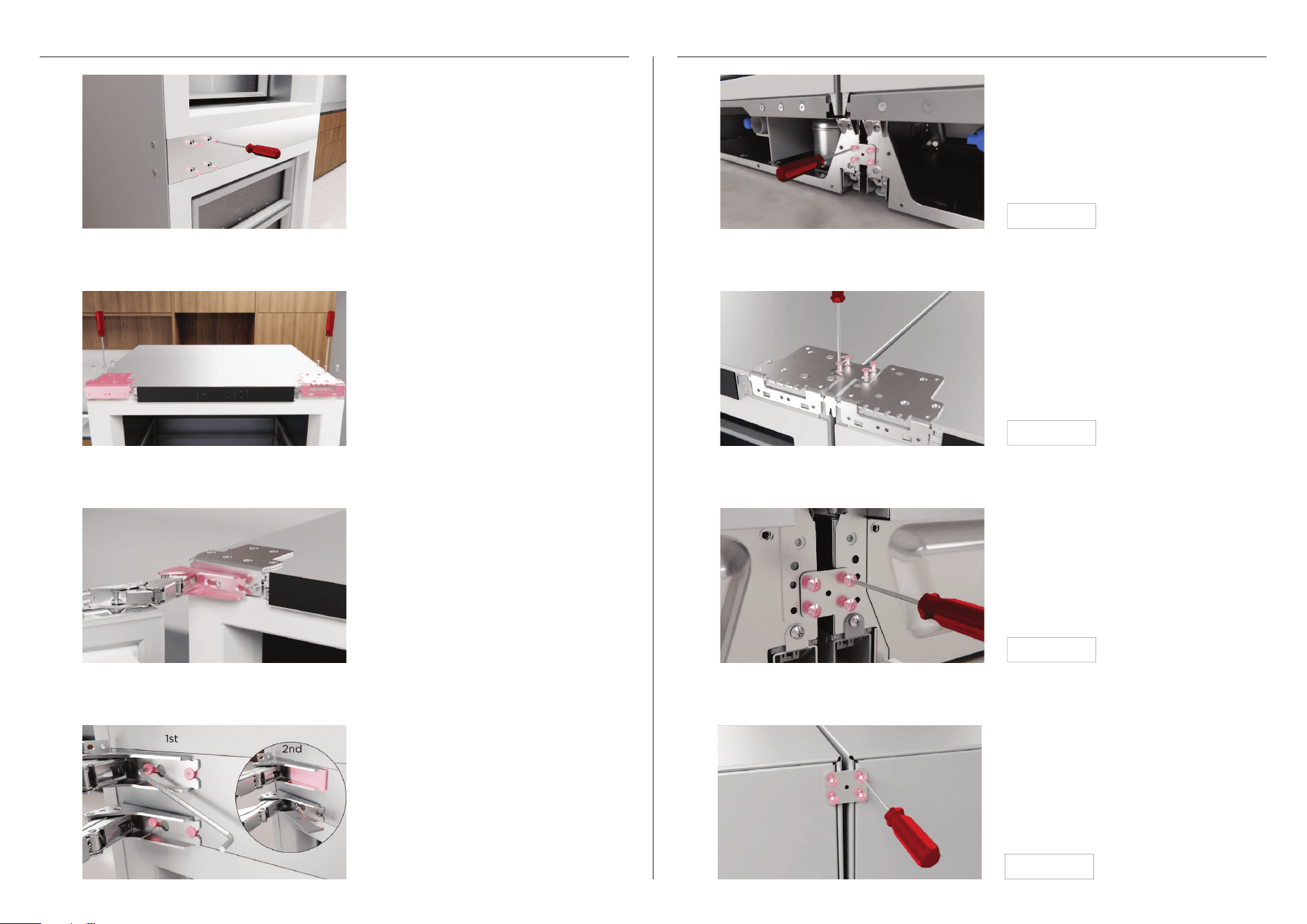
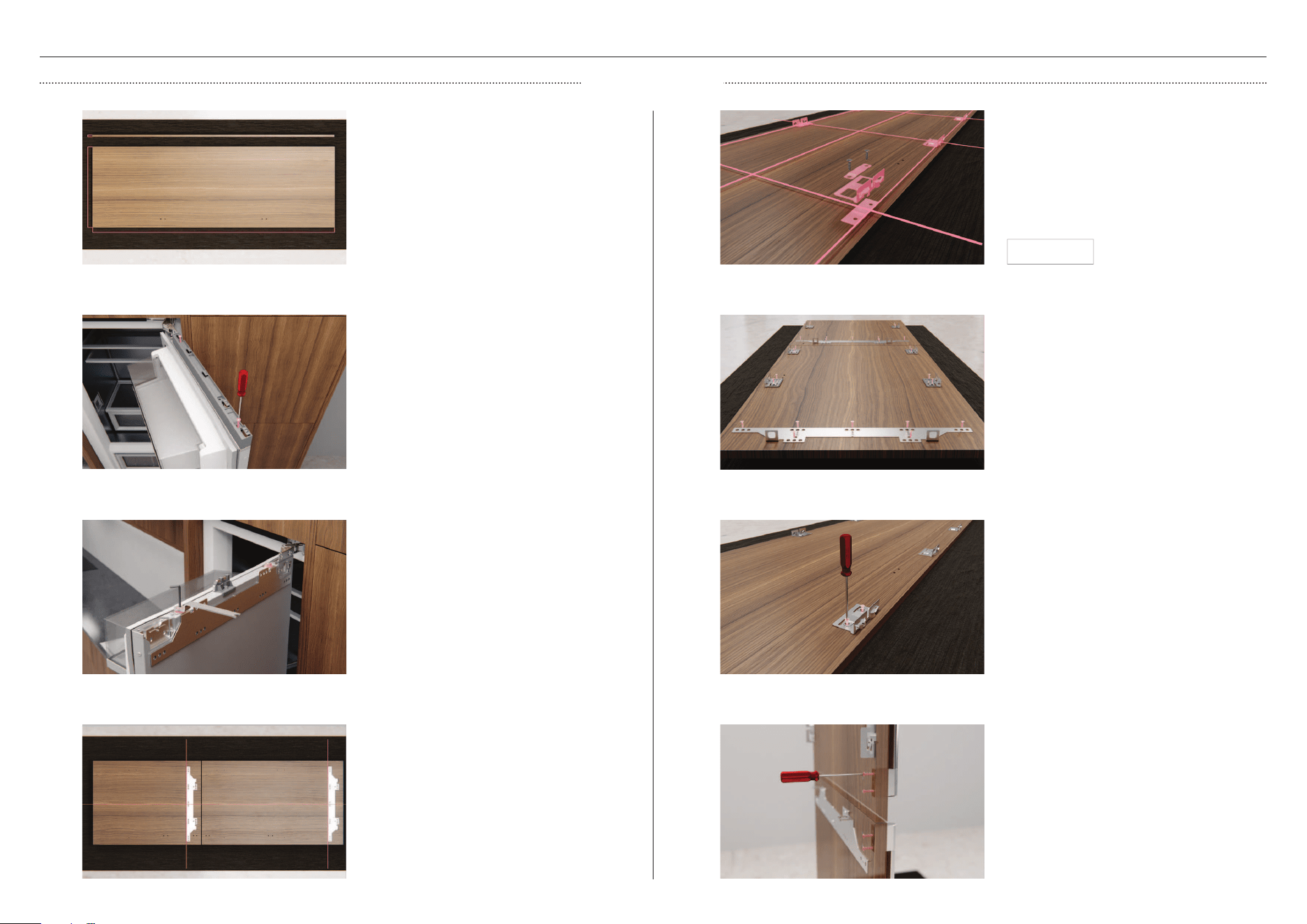
DOOR PANEL PREP
CUSTOM PANEL
4
Align the centre door panel bracket to
panel ensuring the ‘V’ in bracket is to sit
on the centreline.
Secure the handle to the panels using
4xM5x25 hex screws per handle.
Ensure handle fixings do not interfere
with side brackets.
8
Recheck door panel size and
specifications ensuring all bracket
locations have been marked. Refer to
page 14 for details.
Alternately, the supplied door panel
template can be used to mark
bracket locations.
1
Align the side brackets to panel.
5
Install kit F
Remove both washers and nuts and set
aside. Lift the panel brackets upwards
to remove.
3
7
Secure the side brackets using two
screws per bracket. Ensure side brackets
are fitted tightly and the fasteners are
secured straight.
Remove both top covers. Set aside.
2
Using the screws supplied in the install
kit, secure the door panel bracket using
seven screws.
6
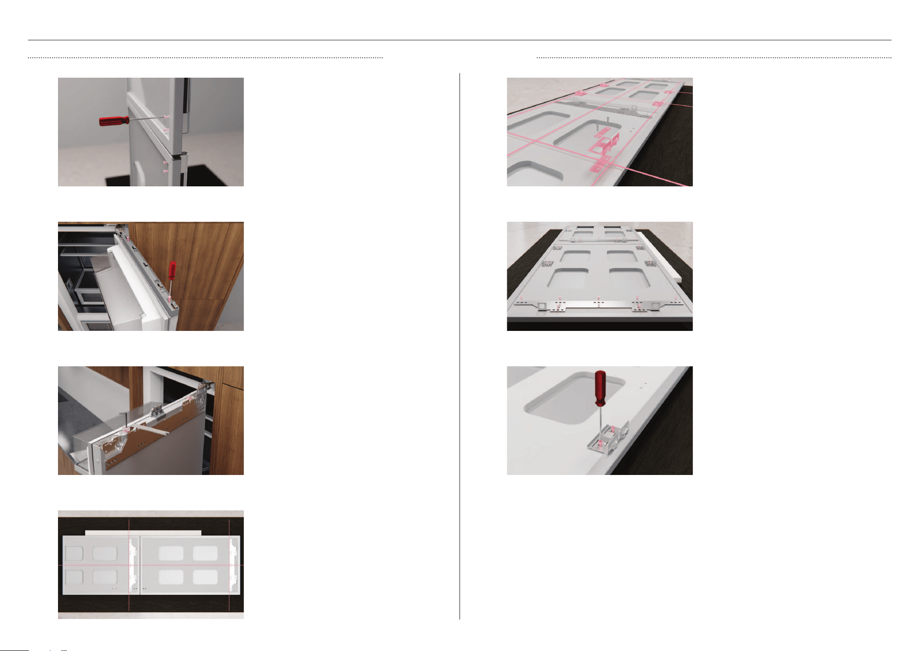
26
4
Align the centre bracket to pre-drilled
holes on the panel.
DOOR PANEL PREP
STAINLESS STEEL PANEL
Determine the panel orientation based
on the hinge and handle position.
Remove the four handle plugs from the
door panel. Align and secure handle
using M5x25 screws from handle kit.
Repeat for lower door.
1
Remove all blue tape from the panel.
Align the side brackets to the pre-drilled
holes on the panel.
5
Remove both washers and nuts and set
aside. Lift the panel brackets outwards
to remove.
3
7
Secure the side brackets using two
screws per bracket from the supplied
panel kit. Ensure side brackets are
fitted tightly and the fasteners are
secured straight.
2
Using the screws supplied in the panel
kit, secure the door panel bracket using
seven screws.
6
Remove both top covers using a
powered driver. Set aside.
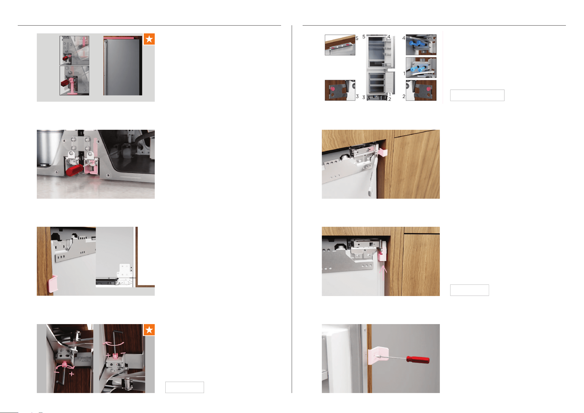
27
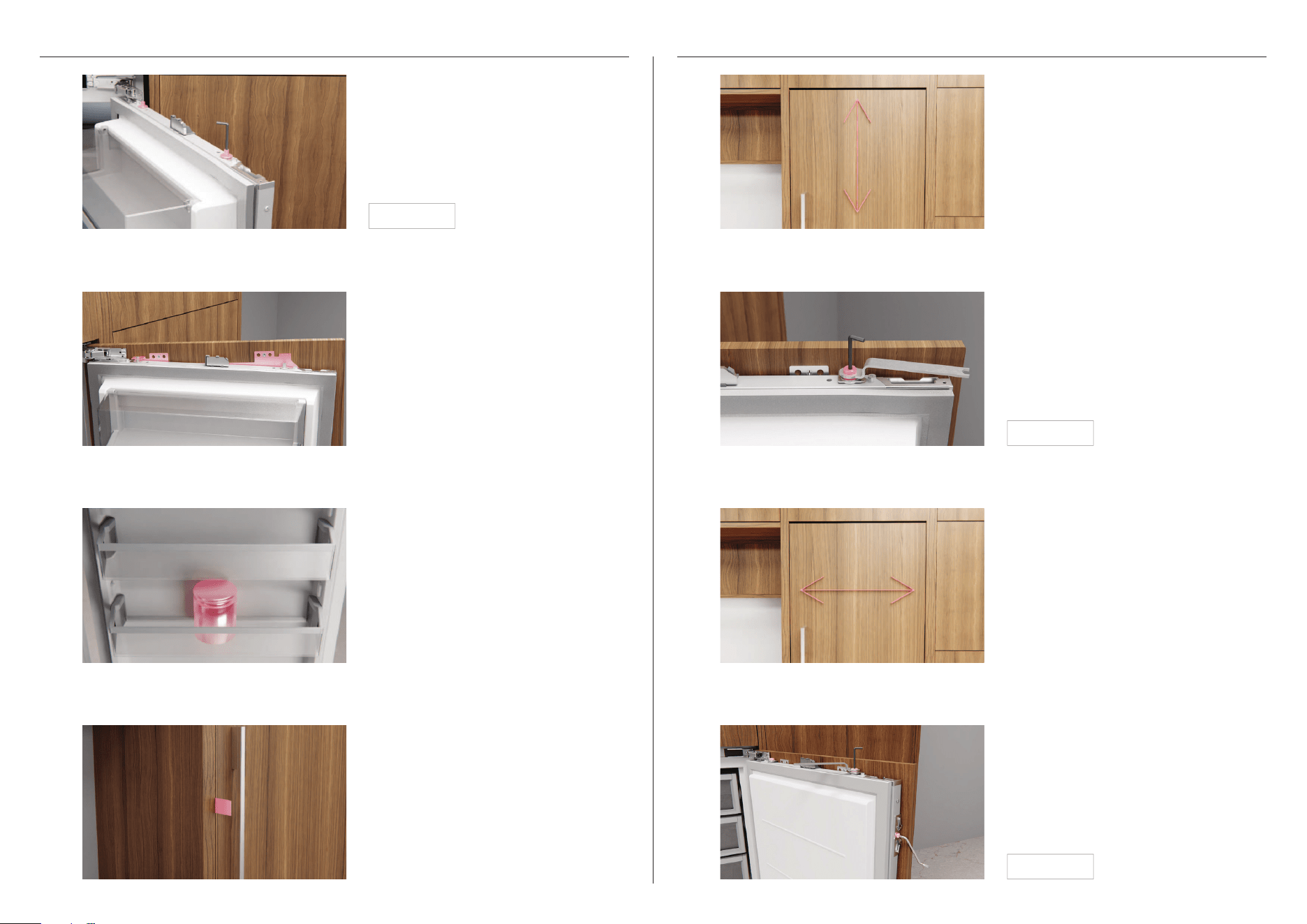
ALIGN DOOR PANEL SECURE DOOR PANEL
Locate the top of the door to the two
mounting screws and lower.
2
Loosely tighten the side screws and the
top M8 washers using the spanner and L
key provided in the install kit.
2
Install kit D
Using a piece of tape, fit a tab on the
door to assist in opening the door
without disturbing panel settings.
4
4
Fit side screws to panel using the short
crosshead tool provided in the install
kit. For 90° door opening installs, the
supplied crosshead key should be used
on the hinge-side.
Tighten all side screws and the top M8
washer and nut to secure.
Install kit D
Ensure top mounting screws have
been loosened and sit at their
lowest position.
1
Ensure side brackets are disengaged
and the top mounting screws have
been loosened. Rotate the mounting
studs clockwise to lower the panel and
anticlockwise to raise it.
1
Install kit D
We recommend loading the shelves in
the door with 33lb (15kg) weights to
ensure accurate panel gap widths.
3
Push panel side-to-side to adjust
horizontally. Ensure panels are flush with
front of cabinet.
3
28
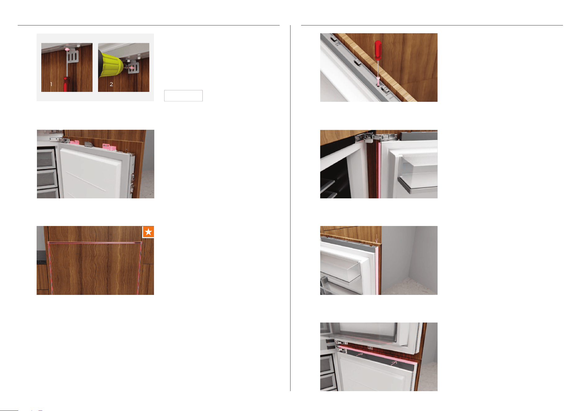
SECURE DOOR PANEL FIT TRIMS AND GRILLE
6
Fit the lower panel using the
same process.
Locate the shorter door trim to the
hinge-side of the product, and slide
down to clip in place. If a gap is present,
remove and readjust the side brackets.
Repeat for lower door.
2
4
Fit the top trim on the lower door.
Open the door and loosen the lower
bracket screw. Adjust the bracket until it
rests against the door panel. Re-tighten
the screw and fit an additional screw to
secure to panel.
5
Fit the top cover using two screws.
Ensure flat side faces out from the
panel. Repeat for the lower door.
1
Install kit E
7
Recheck all gaps and any clashing.
Locate the longer door trim to the non-
hinge-side of the product and slide
down to clip in place. If a gap is present,
remove and readjust the side brackets.
Ensure trim does not protrude above
the top cover. Repeat for lower door.
3
29
FIT TRIMS AND GRILLE
Hinge swap installs only:
Swap the bottom hinge and non-hinge
trims on the grille.
Open the cover and align the grille to
the product. Slot into place starting
with the base of the grille. Hand tighten
the top left screw first, followed by the
top right screw. Fit the remaining five
screws on the grille to secure.
Fit the top UI trim taking into account
the hinge location.
5
6
7
Install kit H
Ensure top of trim touches alcove before
securing using the supplied fastener.
Locate trim between products. Lower
trim before pushing in to ensure
bottom connector bracket clears the
grille. Slide trim up until it slots into the
top bracket.
1
2
CENTRE TRIM INSTALL (MULTIPLE PRODUCT INSTALLS ONLY)
Joiner kit A
30
Measure distance from floor to bottom
of grille to determine the position of the
toe kick mounting plate.
Secure supplied toe kick mounting plate
in trim kit to the toe kick panel.
Recheck toe kick panel size and
specifications. Refer to page 13
for details.
1
2
TOE KICK PANEL PREP
Install kit E
Slide both depth adjustment brackets
all the way forward and slightly tighten
the screws.
Loosen the screws on both toe kick
depth adjustment brackets.
Attach the toe kick to the depth
adjustment brackets. The magnets
should auto-locate.
1
2
3
4
Push the toe kick back to the desired
depth before removing. If toe kick depth
is less than 3 9/16” (90mm), attach the
additional foam block.
Hand tighten the depth adjustment
screws and refit the panel.
SECURE TOE KICK
31
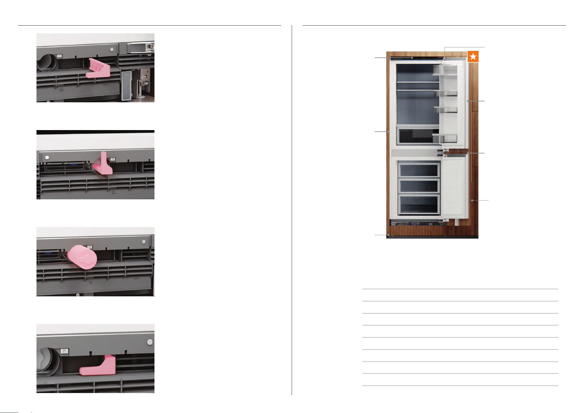
Align flow divider to the screw at the
bottom of the door and slot into place.
Secure to the door panel using the
provided screws.
Measure the distance between the
bottom of the door and the base of
the door panel. Cut the flow divider
to length.
Cut the seal to length and clip onto the
front of the flow divider. Ensure tabs on
the seal and flow divider align.
5
6
7
8
On the UI, press and hold to exit
installer mode.
Install kit D
WI-FI SET UP
Setup
i-Fi
Settings
37.0°F
Fridge
Pantry
54.0°F
Chill
32.0°F
Setup
i-Fi
Settings
Setup
Wi-Fi
Your appliance may be connected to your home wireless network and operated remotely
using the app.
z
Ensure your home Wi-Fi network is turned on.
z
You will be given step by step guidance on both your appliance and mobile device.
z
It may take up to 10 minutes to connect your appliance.
1
2
3
4
Press
to display the menu.
Press
or to scroll through the
list and select SETTINGS.
Press
to confirm.
Press
or to scroll through the
list and select WI-FI SETUP. Press
to confirm.
Open the
FISHER & PAYKEL app on
your mobile device. Follow the
onscreen guidance.
On your mobile device:
1 Download the app from www.fisherpaykel.com/connect
2 Register and create an account.
3 Add your appliance and set up the Wi-Fi connection.
ONNECTED
i-Fi
3D4
TBPHMPNQ
Connect
To complete
connection,
follow the app
instructions
SECURE TOE KICK
32
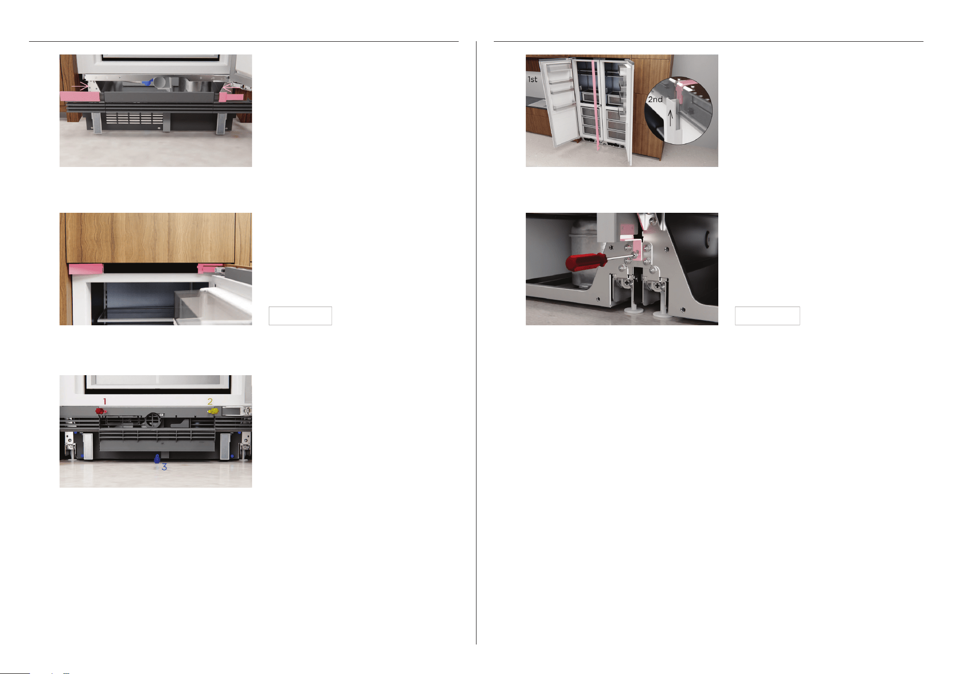
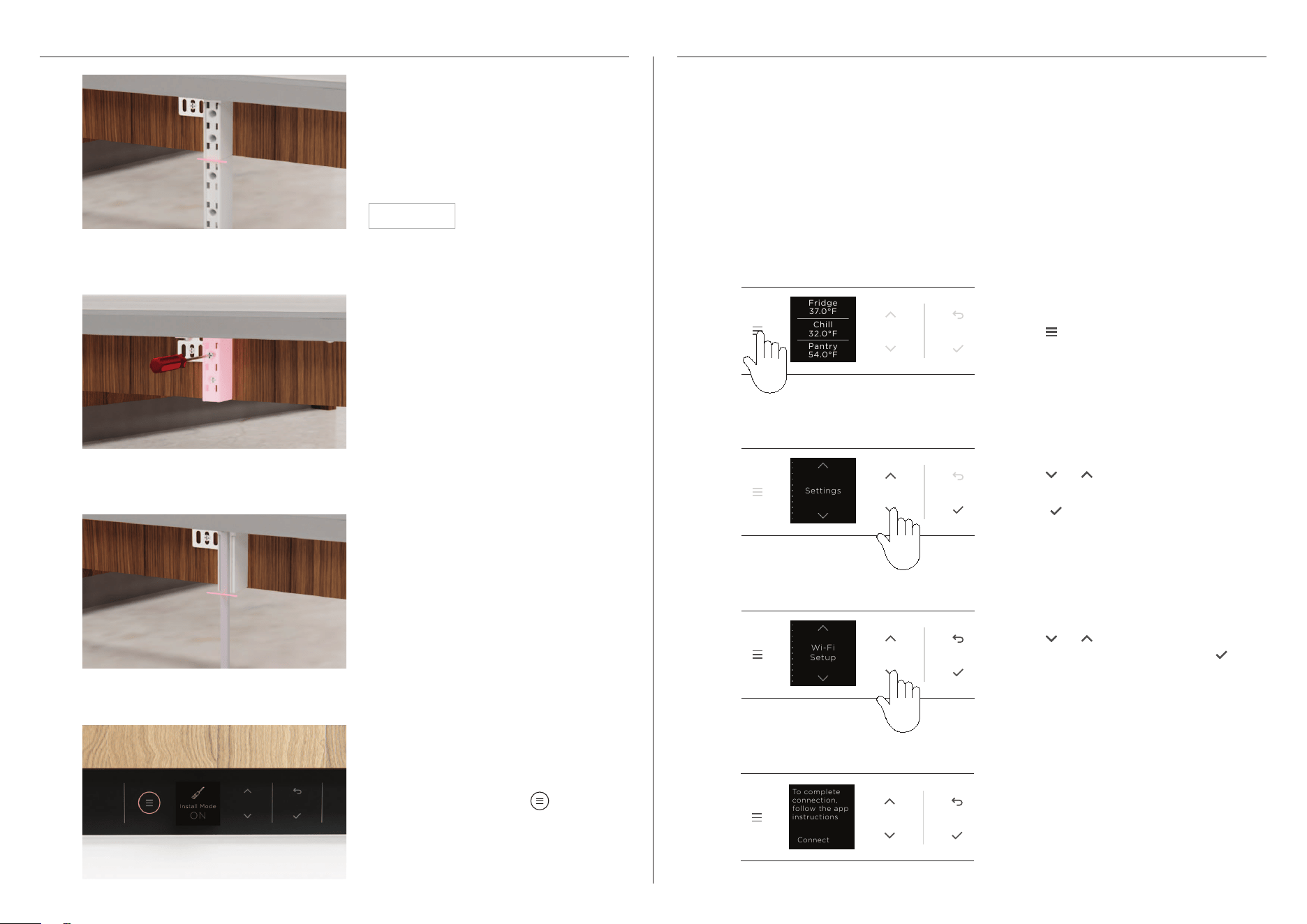
FLUSH WATER THROUGH THE WATER DISPENSER FLUSH WATER THROUGH THE ICE MAKER
Press the water dispenser pad and
dispense a total of 2 Gallons of water.
A harmless carbon residue may be
dispensed with the water during
this process.
Press
to display the menu.
Ensure power and water connections
have been turned on.
Ensure power and water connections
have been turned on.
When dispensing for long durations, a
time out period may occur where an
alarm will sound. Please wait 4 minutes
before dispensing again.
Press
or to scroll through the list
and select ICE.
Press
to turn ice maker on.
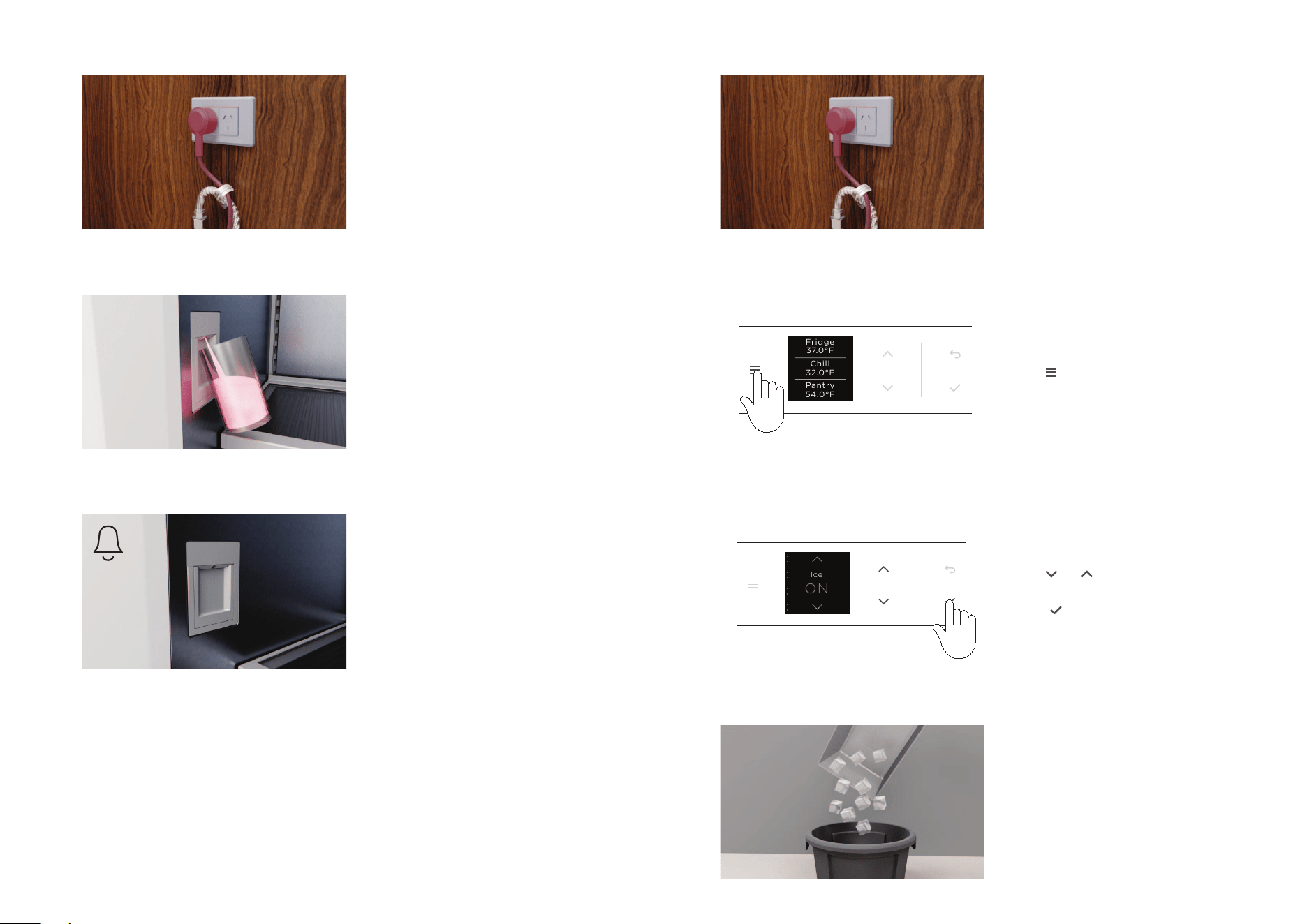
The flushing process will be complete
after the first full bin of ice is produced.
We recommend discarding this batch of
ice as it may appear slightly discoloured
and contain a harmless carbon residue.
1 1
2 2
3 3
4
Ice
ON
Setup
i-Fi
Settings
37.0°F
Fridge
Pantry
54.0°F
Chill
32.0°F
33
Complete and keep for safe reference:
Model
Serial no.
Purchase date
Purchaser
Dealer address
Installer’s name
Installer’s signature
Installation company
Installation date
INSTALLER CHECKLIST
Installer mode has been
exited
All trims have been secured
at all attachment points
Hinge limiting pins have
been fitted if required
Levelling feet have been
adjusted and engaged
If water is turned on,
purge before first use
All panel gaps and any
potential clashing points
have been checked
All covers are in place
Product is robustly
attached to cabinetry
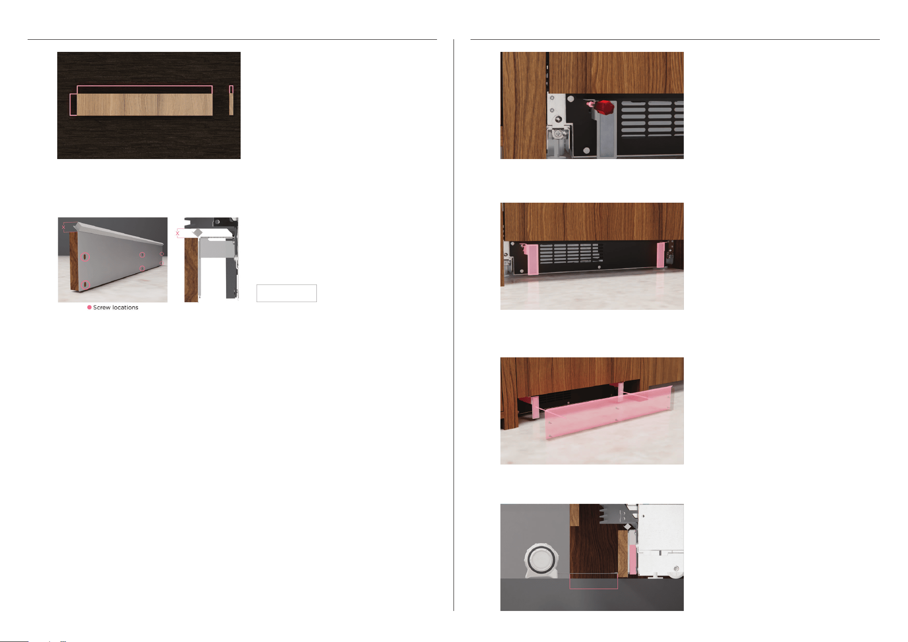
REPLACING WATER FILTER
Using the filter tool, rotate filter 90⁰
anti-clockwise to unlock and remove.
Push grille flap to access filter. Pull tool
outwards to remove.
Remove packaging. Ensure filter handle
is positioned horizontally and push all
the way in. Rotate clockwise to lock
into place.
1
2
3
4
Slot tool into place and push to close
the grille flap.

34
Empty contents.
Reverse the installation process to remove
from alcove. Ensure doors are taped shut
and safe handling practices are observed.
1
2
3
SAFE PRODUCT REMOVAL
Remove the flow divider and panel
bracket before removing all door panel
side screws and the M8 washer and nut.
Lift panel up and out to remove.

867869A 09.22
FISHERPAYKEL.COM
© Fisher & Paykel Appliances 2022. All rights reserved.
The models shown in this guide may not be available in all markets
and are subject to change at any time.
The product specifications in this guide apply to the specific products and
models described at the date of issue. Under our policy of continuous product
improvement, these specifications may change at any time.
For current details about model and specification availability in your country,
please go to our website or contact your local Fisher&Paykel dealer.