
Loading ...
Loading ...
Loading ...
AXIS 221/223M Installation Guide Page 5
ENGLISH
ENGLISH
ENGLISH
Connect the cables
1. Connect the camera to the network using a shielded network cable.
2. Optionally connect external input/output devices, such as alarm devices. See page 13 for
information on the terminal connector pins.
3. Optionally connect an active speaker and/or external microphone (AXIS 223M only).
4. Connect power, using one of the methods listed below:
• PoE (Power over Ethernet). If available, this is automatically detected when the
network cable is connected (see above).
• Connect the supplied indoor power adapter* to the power connector on the
camera.
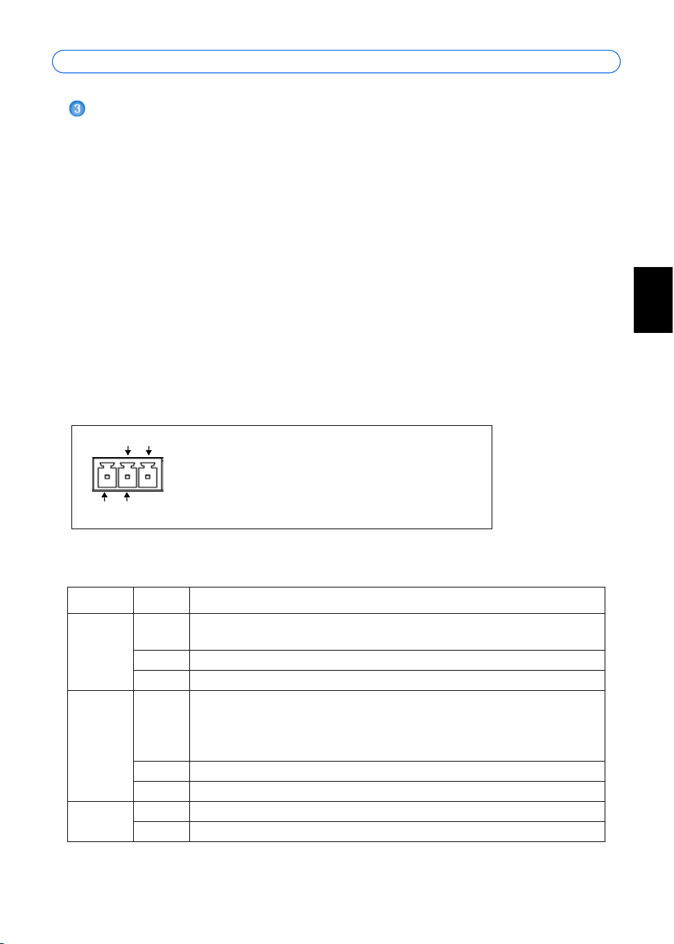
• The 3 pin power connector block on the rear panel. See the illustration below.
5. Check that the LED indicators show the correct conditions. See the table below for
further details. Note that some LEDs can be disabled and may be unlit.
3 pin power connector block
LED indicators
* only use the supplied PS-K power adapter
LED Color Description
Network Green Steady for connection to 100 Mbit/s network. Flashes for network
activity.
Amber Steady for connection to 10 Mbit/s network. Flashes for network activity.
Unlit No connection.
Status Green Shows steady green for normal operation. Note: The Status LED can be
configured to be unlit during normal operation, or to flash only when the
camera is accessed. See the online help files for more information. Go to
Setup > System Options > LED settings
Amber Steady during startup, reset to factory default or when restoring settings.
Red Slow flash for failed upgrade.
Power Green Normal operation.
Amber Flashes green/amber during firmware upgrade.
GND DC+
Connect DC power (7-24V) on pins 1 and 2.
Connect AC power (10-24V) on pins 2 and 3.
AC AC
1
2
3
Loading ...
Loading ...
Loading ...