MODEL 2PACD250
OWNER’S MANUAL
250 PINT COMMERCIAL DEHUMIDIFIER

Model 2PACD250
Power Supply 115V/60Hz/1Ph
Rated Input Current 5.3 amps at 65°F 60%RH
Rated Input Power 578 watt at 65°F 60%RH
The Air Volume 235CFM
Dehumidication Capacity (80°F / 60% RH) 140PPD
Dehumidication Capacity (90°F / 90% RH) 250PPD
Filter SUS304 washable
Power plug length 25ft
Drain hose length 20ft
Net weight 126 lbs
Unit Size (W×H×D) 23 x 33 x 22 inch
Refrigerant/Charge (OZ) R410A/24.7oz
PRODUCT PARAMETER TABLE

3
IMPORTANT SAFETY INSTRUCTION ............................................................................................. 4
SAFETY TIPS .................................................................................................................................................................................. 4
NOTICE OF OPERATION ............................................................................................................................................................ 4
IDENTIFICATION OF PARTS ............................................................................................................. 5
PRODUCT DESCRIPTION .......................................................................................................................................................... 5
INSTALLATION GUIDE................................................................................................................................................................. 6
OPERATING INSTRUCTIONS ............................................................................................................ 7
CONTROL PANEL ......................................................................................................................................................................... 7
CONTROL PANEL FEATURES .................................................................................................................................................. 8
BUTTONS ..............................................................................................................................................................................................................................8
ICONS .....................................................................................................................................................................................................................................9
POWER-ON AUTOMATIC DETECTION ...............................................................................................................................11
COMPRESSOR PROTECTION FOR THREE MINUTES ...................................................................................................11
POWER-DOWN MEMORY FUNCTION .................................................................................................................................11
APP CONTROL ............................................................................................................................................................................11
ADJUST THE HEIGHT HANDLE .............................................................................................................................................12
CLEANING THE AIR FILTER .....................................................................................................................................................12
TROUBLESHOOTING........................................................................................................................13
WIRING DIAGRAM.......................................................................................................................................................................13
ERROR CODES ............................................................................................................................................................................13
BOM .................................................................................................................................................................................................14
PARTS LIST ...................................................................................................................................................................................15
TABLE OF CONTENTS
IMPORTANT NOTE:
Read the manual carefully. Make sure to save this manual for future reference. Illustrations in this manual
are for explanatory purposes only, your actual product may look slightly dierent.
Stand dehumidier upright for full 24 hours before
initial start up to allow refrigerant to settle.
Always use and store dehumidier in an upright position.

4
IMPORTANT SAFETY INSTRUCTION
BEFORE INSTALLING AND USING YOUR DEHUMIDIFIER, PLEASE READ THIS OWNER'S
MANUAL CAREFULLY. STORE THIS MANUAL IN A SAFE PLACE FOR FUTURE REFERENCE.
The use of electrical products may create hazards that include, but are not limited to injury, re,
electric shock. Failure to follow these instructions may damage and/or impair its operation and
void the warranty.
SAFETY TIPS
• Before operating, remove all packaging
material and check for any damage that may
have occurred during shipping or any missing
items.
• Check household power supply to ensure it
matches the specication of appliance.
• Always place the unit on a level surface.
• NEVER use or store gasoline or other
ammable vapor or liquid near this unit unless
instructed by this manual.
• DO NOT lay power cord under carpeting.
DO NOT cover cord with throw rugs, runners,
or similar coverings. DO NOT route cord under
furniture or appliances. Arrange cord away
from trac area and where it will not be
tripped over.
• To reduce the risk of re or electric shock,
DO NOT use this appliance with any solid-state
speed control devices.
• DO NOT touch this appliance or the plug with
wet hands or while standing in water.
• Maintain a 12-18inch clearance space a round
this unit. DO NOT block or cover air inlet or
outlet grilles.
• The unit must be connected to a correctly
grounded power supply.
• DO NOT start or stop the unit by inserting or
pulling out the power plug.
• DO NOT use an adapter plug or extension
cord.
• DO NOT use the unit in the immediate
surroundings of a bath, a shower or a
swimming pool.
• DO NOT insert anything into the air outlet.
DO NOT obstruct air inlet or outlet grills unless
instructed by this manual.
• DO NOT direct the air ow at human faces or
bodies.
• DO NOT let children play near this unit.
• Always inspect the cord for signs of damage
before use. If the power cord is damaged, it
must be replaced by the manufacturer or a
qualied service technician.
• DO NOT attempt to repair or adjust any
electrical or mechanical functions of this
appliance, as this may cause danger and void
the warranty.
• If the appliance is damaged or it malfunctions,
DO NOT continue to use it. Unplug the product
and refer to troubleshooting guide or contact
the seller.
• Make sure the unit is turned o and unplugged
before cleaning or servicing this unit.
NOTICE OF OPERATION
• After the unit has stopped, it cannot be
restarted immediately in the rst 3 minutes.
Wait 3 minutes before resuming operation to
prevent damage to compressor.
• The operating temperature is 33-110°F.
• We suggest wash/change the lter once
every 3 months.
• Clean the drain hose after operation to avoid
any clogs.
• Before operating the dehumidier connect
the included drain hose using the provided
drain couplers. Do not block the drain hose.
The end of the drain hose should not be
higher than 16-feet above the outlet hole.
If the drain hose end is too high, water will
not drain properly and could damage the unit.
5
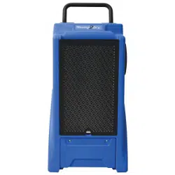
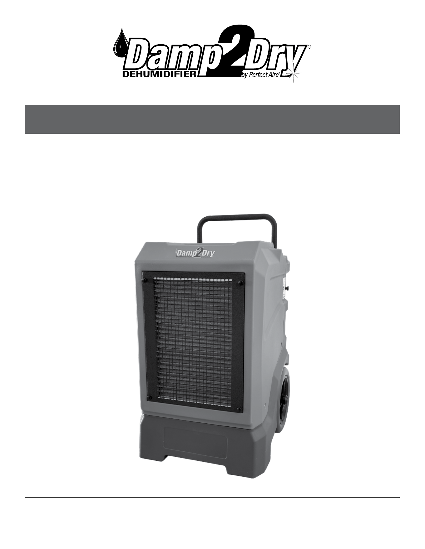
IDENTIFICATION OF PARTS
PRODUCT DESCRIPTION
Wheel
Handle
Air Intake
Air Outlet
Control Panel
Drain Coupler
6
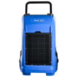
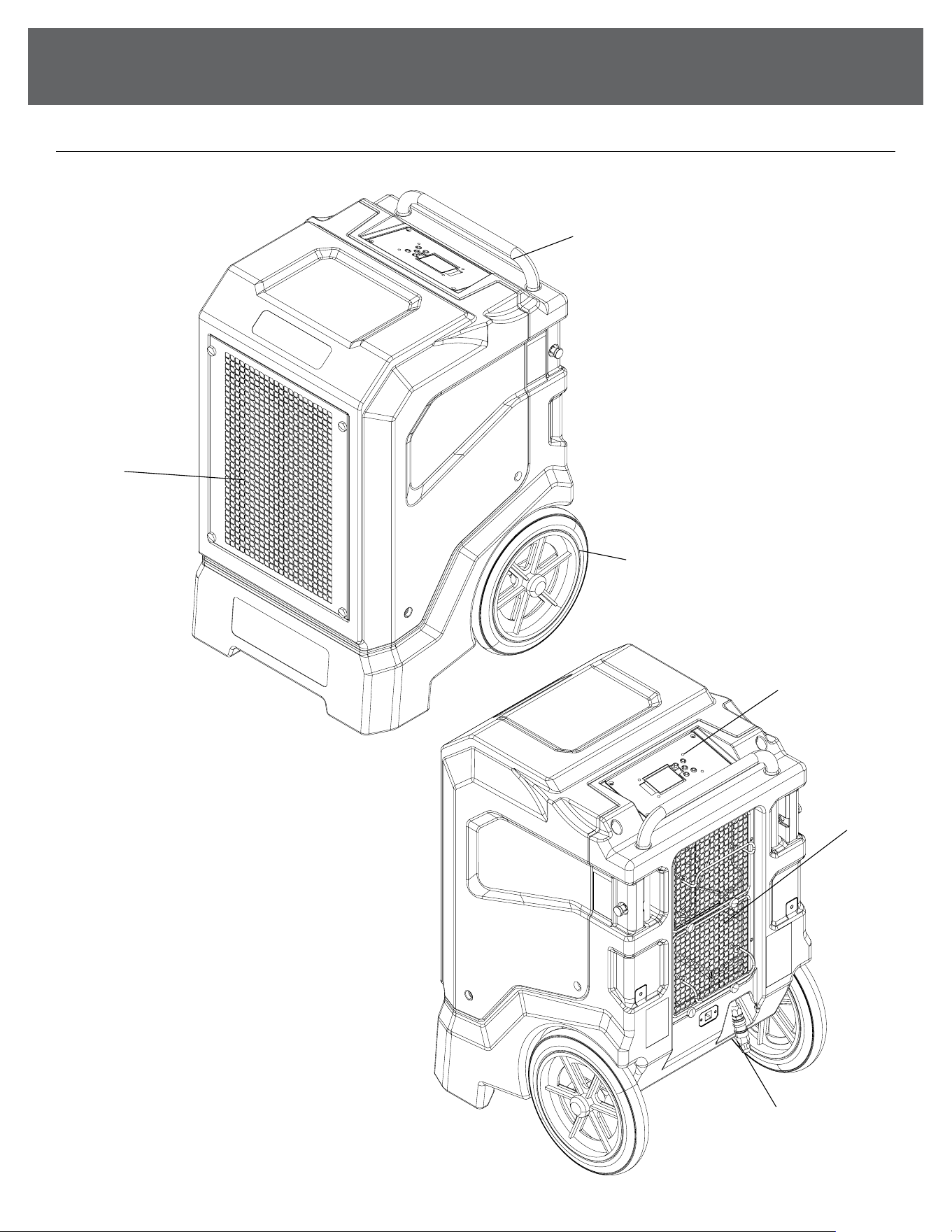
IDENTIFICATION OF PARTS
(Continued)
INSTALLATION GUIDE
• Connect the drain hose to the machine's drain, making sure the two ttings are securely connected
• The machine's drain outlet is located as shown above
• Use a separate container to collect drain and periodically check for fullness, or run the drain directly to a
oor drain or sink.
7
OPERATING INSTRUCTIONS
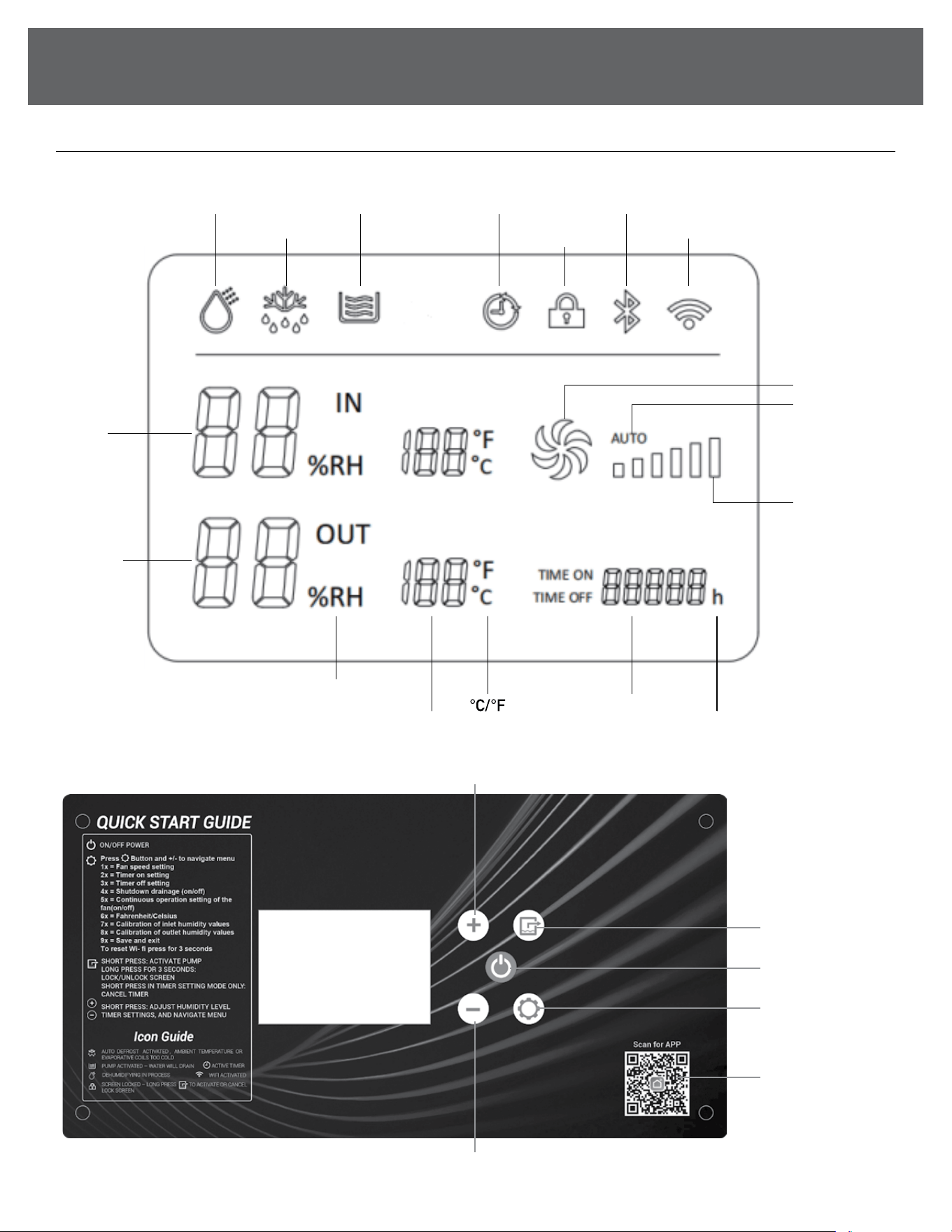
CONTROL PANEL
Running
Defrost
Draining Timer
Screen
/Child Lock
WIFI
Fan
Accumulated
Running TimeTemperature
Relative
Humidity
Inlet
Humidity
Outlet
Humidity
Fan Speed
( Low/High )
AUTO
(Fan)
Bluetooth
ON/OFFON/OFF
++
--
System
Function
Settings
Manual Drain
Cancel Timer
(in timer mode)
Screen Lock
WIFI App
QR Code
8
OPERATING INSTRUCTIONS
CONTROL PANEL FEATURES
NOTE: The following control panels are for explanation purpose only. The control panel of the unit you
purchased may be slightly dierent according to the models. Your machine may not contain some
indicators or buttons. The actual shape shall prevail.
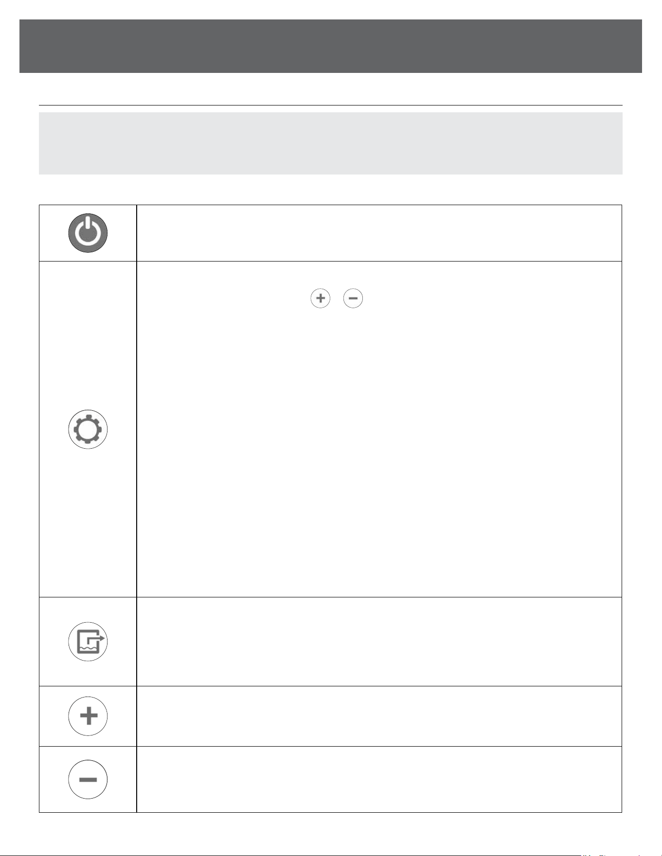
BUTTONS
ON/OFF power button.
SYSTEM FUNCTION SETTINGS
SHORT PRESS in sequence and use
or to navigate the menu. After 5 seconds of no activity on
the control panel, it will save the settings and close the menu:
1x = Fan speed setting
2x = Timer on setting
3x = Timer o setting
4x = Shutdown drainage (ON/OFF)
NOTE: ON setting will instruct the machine to pump out all water in reservoir every time the dehumidier is
powered o.
5x = Continuous operation setting of the fan (ON/OFF)
6x = Fahrenheit/Celsius
7x = Calibration of inlet humidity values
8x = Calibration of outlet humidity values
9x = Save and exit
LONG PRESS for 3 seconds to reset the WiFi module.
(Under humidity calibration setting, we can adjust it by press button + and -, with an adjustable range
of -10~10. For example, when the humidity display value of the dehumidier is observed to be 5% lower
than the humidity detected by separate detectors, the value needs to be adjusted to "5")
SHORT PRESS to start the water pump drainage.
LONG PRESS for 3 seconds to lock or unlock the screen. Lock screen feature cannot be activated when
machine is powered o.
SHORT PRESS WHEN SETTING TIMER: Cancels timer
Increase value on timer, humidity setting, and navigate menu.
Decrease value on timer, humidity setting, and navigate menu.
(Continued)
9
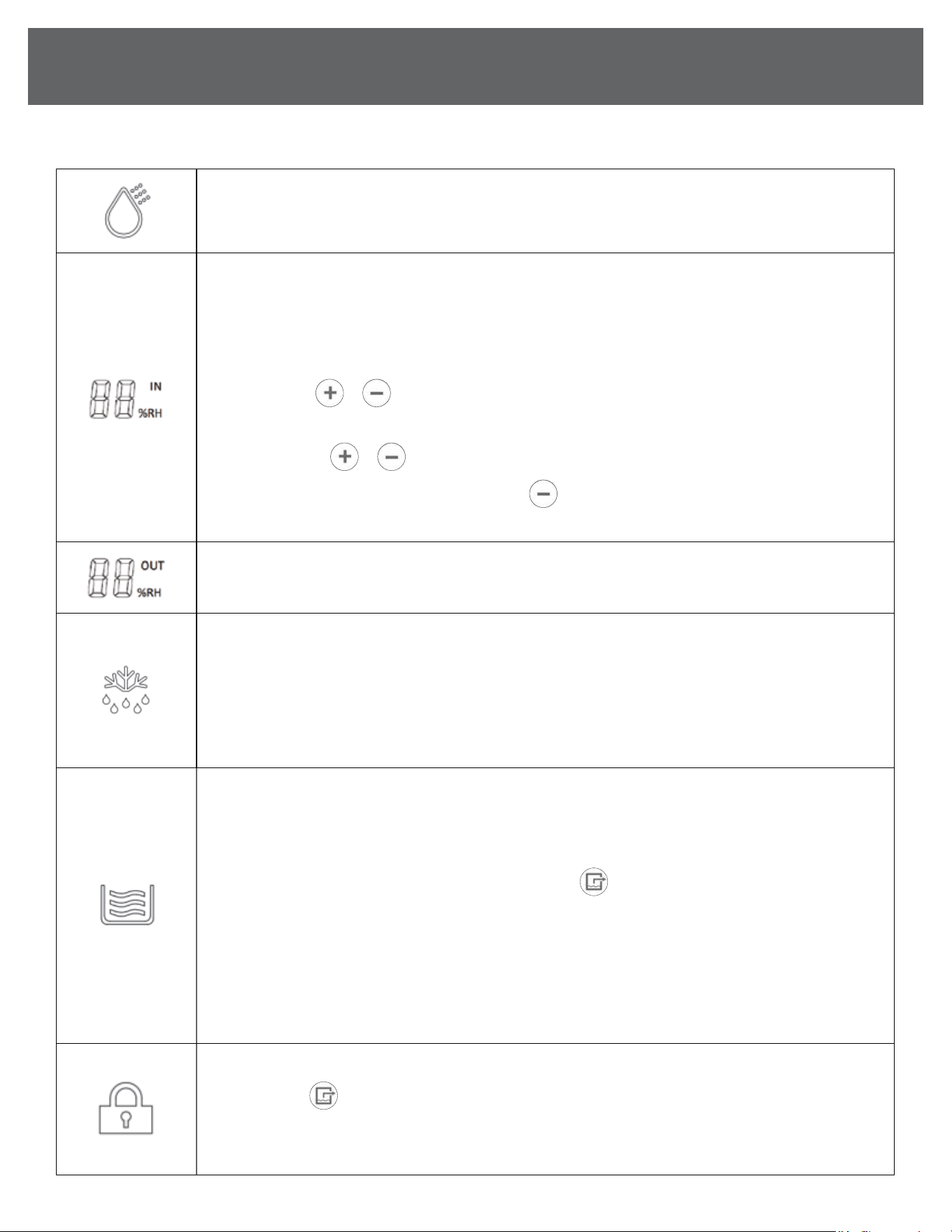
After connecting the power, short press the "on-o key" to turn it on, the dehumidication function is
turned on, and the icon is displayed; press the power o again, the dehumidication function is turned o,
and the icon is not displayed.
SET HUMIDITY LEVEL
• During normal operation, current room humidity will show on the screen.
• Upon power-up, the default humidity value is 30%, AUTO fan speed when powered on.
• The humidity level can be set between 30-90%.
SHORT PRESS
or keys to adjust the set humidity level by 1%. The display will ash 3 times, and
after 5 seconds of no activity, the screen will resume showing the current room humidity reading.
LONG PRESS the
or keys to quickly adjust the percentage.
When the set humidity is 30%, SHORT PRESS the
key again to enter the CO continuous
dehumidication mode, the compressor will continue to run regardless of current room humidity.
Shows the humidity reading of the exhausted air.
AUTO DEFROST
When you see this icon on the display, it signals that the evaporator or ambient temperature has dropped
to a level where frost formation may occur. The machine will automatically initiate the defrost mode.
During defrost mode, the dehumidier will temporarily focus on melting any frost that has accumulated
on the evaporator. The dehumidier will automatically resume to the same settings and operation once
the defrost cycle is complete.
When this icon ashes, the machine is draining water.
1) Automatic Drainage: When the system receives the water full signal for ≥3 seconds, the water pump
will activate and drain the water. During this time, the compressor and fan motor will continue to run
and this icon will ash.
2) Manual Drain: After pressing the manual drain button
the water pump will activate and drain the
water. During this time, the compressor and fan motor will continue to run and this icon will ash.
NOTE: If the full water signal is not cleared in 60 seconds, an alarm will sound, the fault code E3 will show,
and the icon will continue to ash.
This machine features a water pump designed for ecient water removal up to a maximum 18ft vertical
height. If the hose exceeds this 18 ft. limit in height, it can lead to pump failure. To resolve this issue,
lower the hose height and attempt operation again.
Screen is locked and will not react to buttons.
LONG PRESS
for 3 seconds to activate and cancel lock screen.
Mobile app can also lock or unlock screen.
Lock screen feature cannot be activated when machine is powered o.
ICONS
OPERATING INSTRUCTIONS
(Continued)
10
(Continued)
OPERATING INSTRUCTIONS
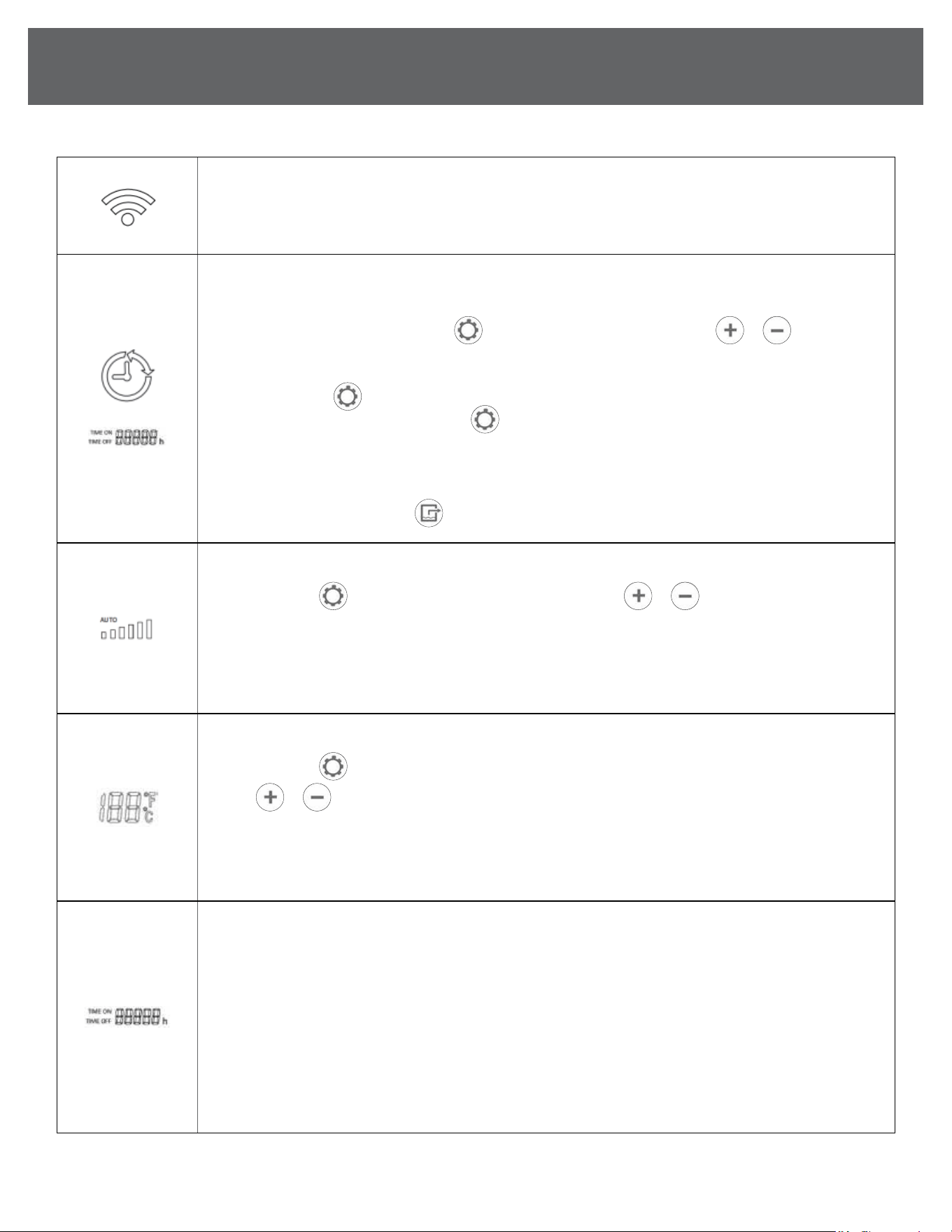
FLASHING: In WiFi pairing mode.
NOT FLASHING: WiFi is connected or connection was successful.
When this icon is displayed, the timing function has been set; when this icon is not displayed, the timing
function has not been set.
1) Timing Setting After pressing the
to enter the timing setting, press the
or to adjust the
hour position by 1 unit, press and hold for 5 seconds to quickly adjust, and the value 00-23 will change
cyclically. After the timer is set on, it will be saved and exited if there is no operation for 5 seconds.
If you press the again within 5 seconds, it will enter the next option of system settings.
2) Timer O Setting After pressing the
to enter the timer o setting, the operation method is the
same as the timer on setting.
3) Cancel Timing The timed on/o setting is automatically canceled after being executed once, and
does not execute circularly, and the timed on/o time becomes 00. When the timer is on or o,
short press the Drain button
to cancel the timer setting, and the current time becomes 00.
Upon power-up, the default fan speed is AUTO.
SHORT PRESS
once to enter the fan speed settings. Press
or to toggle between
AUTO, LOW – HIGH. After 5 seconds of no activity, the setting will save.
Our advanced commercial dehumidier features an AUTO mode, adjusting the wind speed gear based on
the prevailing working conditions. This technology ensures optimal performance and eciency, providing
a hassle-free dehumidication experience.
TEMPERATURE SCALE SETTING
SHORT PRESS
6 times to enter the temperature scale settings.
Press
or
to cycle between degrees Celsius and degrees Fahrenheit.
After 5 seconds of no activity, the setting will save.
IN – Inlet Air Temperature
OUT – Outlet Air Temperature
TIME ON: Timer is set to turn the machine on.
TIME OFF: Timer is set to turn the machine o.
h: The dehumidier's lifetime running timer starts counting when it's powered on and will stop counting
when it’s powered o, either manually or by the 24-hour on/o timer.
• During a fault or abnormal shutdown, the dehumidier will continue to keep track of running time.
• Turning the power o and restarting the dehumidier does not reset the lifetime running timer to zero.
•
The timer display consists of 5 digits, allowing for a maximum count of 99,999 hours before it returns to zero.
• The machine displays the running time in hours.
ICONS
11
OPERATING INSTRUCTIONS
(Continued)
POWER-ON AUTOMATIC DETECTION
After power-on, all displays, indications, and
back-lights will light up for 2 seconds, and the
buzzer will beep briey.
At the same time, the system will conduct
self-checks on communications and sensors,
and the system will enter the shutdown state
when the detection is normal. The device fault
alarm three times.
COMPRESSOR
PROTECTION FOR THREE MINUTES
After the compressor is stopped, it must wait
3 minutes before starting again.
After the compressor is started, it must run for
3 minutes before it can be shut down. If it is a
manual shutdown, it will be shut down immediately.
When the power is turned on for the rst time,
there is no 3 minute delay protection when the
compressor starts.
POWER-DOWN MEMORY FUNCTION
The system has a power-down memory function,
which saves settings about humidity, timing on/o
time, fan speed, and temperature scale, and saves
timing data.
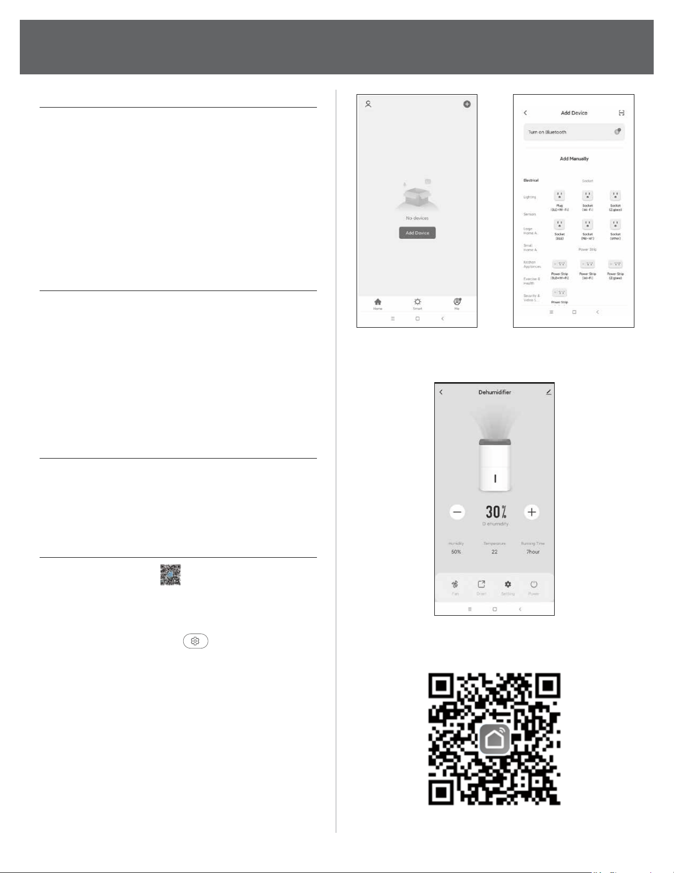
APP CONTROL
(1) Scan the QR code
(on the right) on
your mobile phone to download the
"Smart Life" APP.
(2) Press and hold the setting button on the
machine control panel
for 3 seconds
to reset the WIFI module.
(3) Turn on the Bluetooth of your mobile phone
and open the "Smart Life" APP.
(4) Click "Add Device" in the APP (Figure 1).
(5) The phone will automatically search for nearby
devices, and after discovering the device,
click "Add" (Figure 2).
(6) Enter the WIFI density and display
"Added successfully", you can use the
mobile phone to control the device (Figure 3).
(Figure 1) (Figure 2)
(Figure 3)
APP download
12
(Continued)
OPERATING INSTRUCTIONS
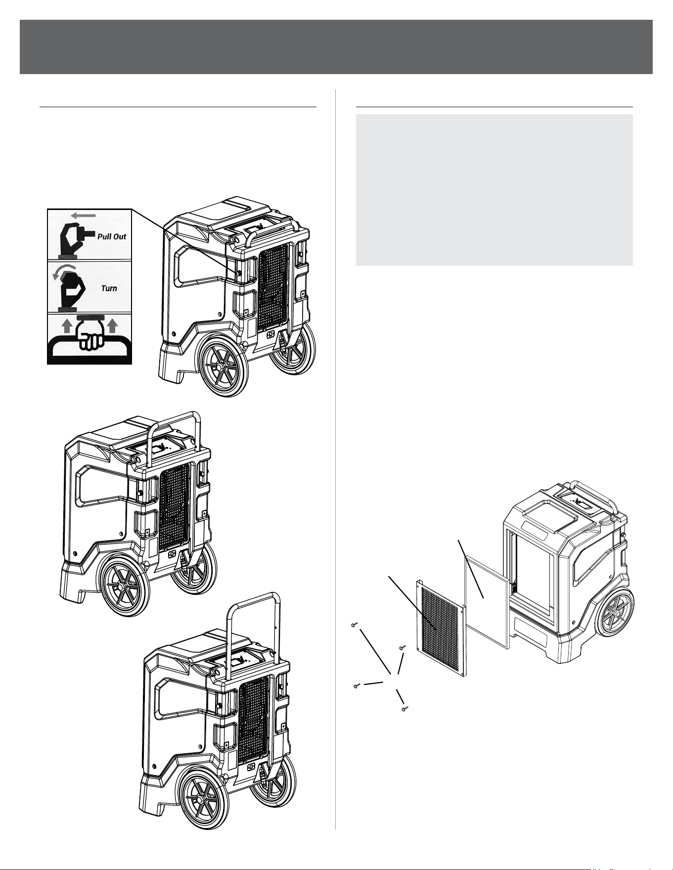
ADJUST THE HEIGHT HANDLE
1. Turn out the handle stopper.
2. Adjust the handle to the appropriate
height gear.
3. Fix it using the stopper.
CLEANING THE AIR FILTER
NOTE: Ensure that the air lter is not worn or
damaged. The corners and edges of the air
lter must not be deformed or rounded. Before
reinserting the air lter, make sure that it is
undamaged and dry! The air lter has to be
cleaned as soon as it is dirty.
We suggest cleaning the lter every 3 months.
Routinely check and clean lter sooner if used
in environments with high air pollution.
1. Remove the air lter from the device.
(Remove the 4 thumbscrews located on
the corners of air intake grill on the front
of the machine)
2. Clean the lter using a slightly damp, soft,
lint-free cloth. If the lter is heavily
contaminated, clean it with warm water
mixed with a neutral cleaning agent.
3. Allow the lter to dry completely.
Do not insert a wet lter into the device
4. Reinsert the air lter into the device.
Thumbscrews
Air Intake Grille
Filter
13
TROUBLESHOOTING
Code Description Solution
E0 Communication Fault
Check the connection between the power board and
display panel and reconnect them
E1 Humidity Sensor A Failure Check the connection of the humidity sensor or replace it
E2 Temperature Sensor A Failure Check the connection of the temp. sensor or replace it
E3 Water Full Alarm/Fault
Check if the water pipe is blocked or replace the
water pump
E4 Coil Temperature Sensor Failure Check the connection of the temp. sensor or replace it
E9 Fan Failure Check the connection of the fan or replace it
E11 Humidity Sensor B Failure (Eb) Check the connection of the humidity sensor or replace it
E12 Temperature Sensor B Fault (EC) Check the connection of the temp. sensor or replace it
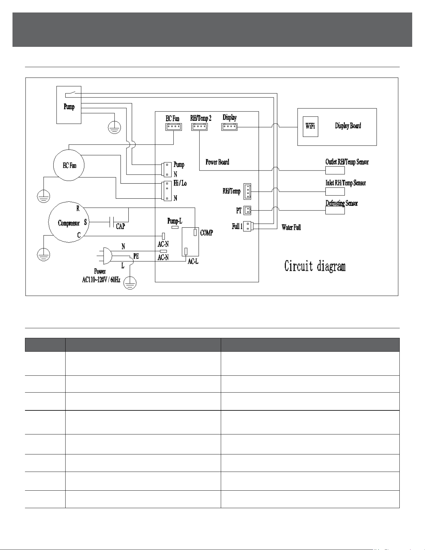
WIRING DIAGRAM
ERROR CODES
14
(Continued)
TROUBLESHOOTING
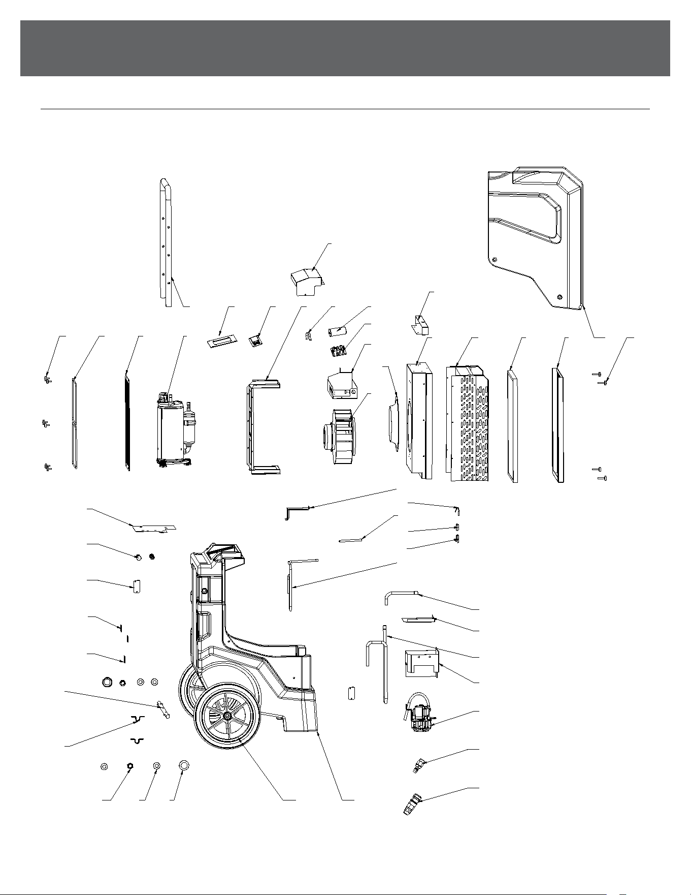
BOM
123
4
5
6
7
8
11 12 13 14
15 16 19
18
23
10
25
24
27 28 29 30 31
32
33
35
38
39
40
41
42
43
4647
17 20 21
22
34
36
37
9
44
45
26

15
TROUBLESHOOTING
NO. DESCRIPTION QTY
1 Dust Cover 2
2 M16 Flat Pad 4
3 M16 Lock Nut 2
4 Axle Fixings 2
5 302001686 - Axle 1
6 Power cord xing plate 1
7 Velcro Cover 2
8
303000068 -
Temperature and humidity sensor
304000043 -
Temperature and humidity sensor box
2
9 Rotary plunger 2
10 Compressor base plate 1
11 Hand nut 6
12 steel ring 2
13 302001680 - Air outlet panel 1
14 301001177 - Compressor 1
15 302001684 - Handle 1
16
302001694 -
Display panel components
309001132 - Display panel
302001695 - Mounting plate
1
17 303001488 - Display Board 1
18 302001674 - Electrical box cover 1
19 302001917 - Fan support 1
20 302001884 - Capacitor hoop 1
21 303001092 - Compressor capacitor 1
22 303001370 - Main Board 1
23 Electrical box 1
NO. DESCRIPTION QTY
24 Wind guide 1
25 303001369 - Fan 1
26 Blocking plate 1
27 302001693 - Middle support plate 1
28
301001025 - Heat exchanger
components
1
29 399001063 - Filter 1
30 302001676 - Air intake grille 1
31 Upper shell 1
32 306001280 - M5 handle nut 1
33 Sink cover 1
34 303000070 - Defrost sensor 1
35 Exhaust pipe 2 1
36
Temperature sensing
head casing
1
37 Temperature sensing head casing circlip 1
38 Exhaust pipe 1 1
39 Return trachea 1 1
40 302001682 - Water pump cover 1
41 Return trachea 2 1
42
302001697 - Water pump cover
1 components
1
43 303000077 - Pump 1
44 304000076 - Quick connector male 1
45 304000079 - Quick connector female 1
46 Lower shell 1
47 399000080 - Wheels 2
(Continued)
PARTS LIST

844-4PA-AIRE | 844-472-2473 | support@perfectaire.us
CANADA SUPPORT 877-997-2473 | supportcanada@perfectaire.us
www.perfectaire.us
5401 Dansher Road
Countryside, IL 60525
Printed in China | 0923_M064