USE AND CARE GUIDE
4
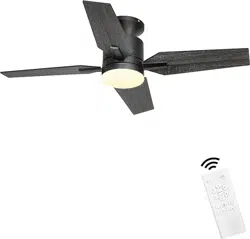
0-INCH CEILING FAN
FLYBULL
Model :
GLX053/GLX054
THANK YOU
We appreciate the trust and confidence you have purchased this ceiling fan. We strive to continually create quality products designed to en
hance your home. Visit us online to see our full line of products available for your home !
Model :GLX053

Dear Customer:
Thank you very much for choosing Ohniyou .
Your choiceis our biggest driving force. We have
been and will continue to be committed to
providing our customers with more high-quality
and low-cost products.
Tips : The installation process of this product is
a bit cum -bersome . and it is estimated that it
will take 0.5-1 hour tocomplete the assembly .
Please be patient to compl etethis assembly
process then you will get a practical pretty
product and a full sense of achievement after
co-mpletion.
If you have any questions in the process of
assembly oruse , please contact us through the
QR code email below as soon as possibleThank
you again for choosing ohniyou
2
Table of Contents ................................................................2
Safety Information ............................................................... 2
Warranty ............................................................................... 3
Pre-Installation .................................................................... 3
Installation ............................................................................ 6
Assembly .............................................................................. 7
Operation ........................................................................... 13
Care and Cleaning .............................................................14
Troubleshooting ................................................................. 14
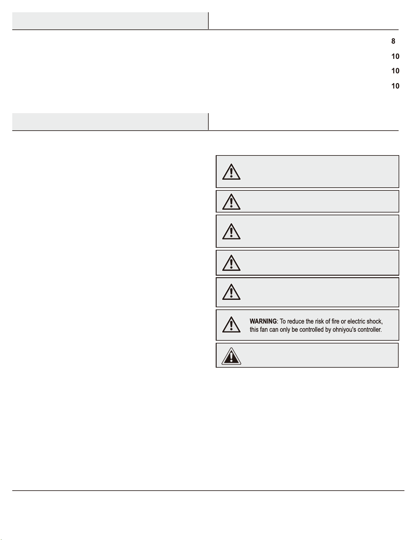
1. To reduce the risk of electric shock, ensure the electricity has been
turned off at the circuit breaker or fuse box before you begin.
2. All wiring must be in accordance with the National Electrical Code
ANSI/NFPA 70-1999 and local electrical codes. Electrical installation
should be performed by a qualified licensed electrician.
3. The outlet box and support structure must be securely mounted and
capable of reliably supporting 35 lbs (15.9 kg). Use only UL Listed outlet
boxes marked “Acceptable for Fan Support of 35 lbs (15.9 kg) or less.”
4. CAUTION: The fan must be mounted with a minimum of 7 ft. (2.1 m)
clearance from the trailing edge of the blades to the floor.
5. Do not operate the reversing switch while the fan blades are in
motion. You must turn the fan off and stop the blades before you
reverse the blade direction.
6. Do not place objects in the path of the blades.
7. To avoid personal injury or damage to the fan and other items, use
caution when working around or cleaning the fan.
8. Electrical diagrams are for reference only. Light kits that are not
packed with the fan must be UL-listed and marked suitable for use
with the model fan you are installing. Switches must be UL General
Use Switches. Refer to the instructions packaged with the light kits
and switches for proper assembly.
9. After making electrical connections, spliced conductors should be
turned upward and pushed carefully up into the outlet box. The
wires should be spread apart with the grounded conductor and the
equipment-grounding conductor on one side of the outlet box.
10. All setscrews must be checked and retightened where necessary
before installation.
WARNING: To reduce the risk of personal injury, do not
bend the blade brackets (also referred to as flanges) during
assembly or after installation. Do not insert objects in the
path of the blades.
WARNING: To reduce the risk of fire or electric shock, this
fan must be installed with an isolating wall switch.
WARNING: To avoid possible electrical shock, turn the
electricity off at the main fuse box before wiring. If you
feel you do not have enough electrical wiring knowledge or
experience, contact a licensed electrician.
WARNING: Electrical diagrams are for reference only.
Optional use of any light kit shall be UL-listed and marked
suitable for use with this fan.
WARNING: To reduce the risk of fire, electric shock, or
personal injury, mount to outlet box marked “Acceptable for
fan support of 35 lbs (15.9 kg) or less,” and use the screws
provided with the outlet box.
Safety Information
Table of Contents
READ AND SAVE THESE INSTRUCTIONS
WARNING: To reduce the risk of fire or electric shock, this fan
should only be used with fan speed control part no. AP-8RDL
manufactured by DawnSun Electronic Technology Co., Ltd.
Zhongshan.
CAUTION: To reduce the risk of personal injury, useonly the
screws provided with the outlet box.
This equipment has been tested and found to comply with the limits for a Class B digital device, pursuant to Part 15 of the FCC Rules. These limits are designed to provide reasonable
protection against harmful interference in a residential installation. This equipment generates, uses and can radiate radio frequency energy and, if not installed and used in accordance
with the instructions, may cause harmful interference to radio communications. However, there is no guarantee that interference will not occur in a particular installation. If this
equipment does cause harmful interference to radio or television reception, which can be determined by turning the equipment off and on, the user is encouraged to try to correct the
interference by one or more of the following measures:
Ƒ Reorient or relocate the receiving antenna.
Ƒ Increase the separation between the equipment and receiver.
Ƒ Connect the equipment into an outlet on a circuit different from that to which the receiver is connected.
Ƒ Consult the dealer or an experienced radio/TV technician for help.
3
Pre-Installation
Warranty
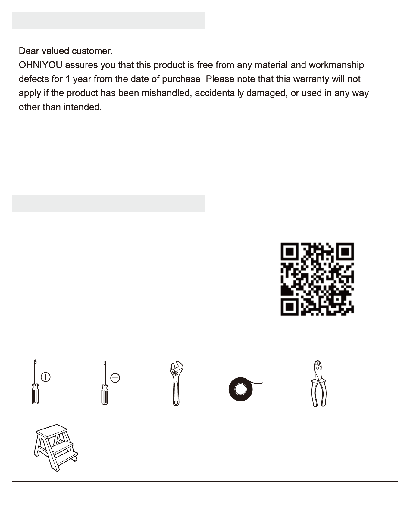
TOOLS REQUIRED
Phillips
screwdriver
Flat blade
screwdriver
Adjustable
wrench
Electrical
tape
Wire
cutter /
stripper
Step ladder
The supplier warrants the fan motor to be free from defects in workmanship and material present at time of shipment from the factory for a
lifetime after the date of purchase by the original purchaser. The supplier warrants that the light kit, excluding any glass, to be free from defects in
workmanship and material at the time of shipment from the factory for a period of five years after the date of purchase by the original purchaser.
The supplier also warrants that other fan parts, excluding any glass or acrylic blades, to be free from defects in workmanship and material at the
time of shipment from the factory for a period of two years after the date of purchase by the original purchaser. We agree to correct such defects
without charge or at our option replace with a comparable or superior model if the product is returned. To obtain warranty service, you must present
a copy of the receipt as proof of purchase. All costs of removing and reinstalling the product are your responsibility. Damage to any part, such as
by accident, misuse, improper installation, or by affixing any accessories, is not covered by this warranty. Because of varying climatic conditions
this warranty does not cover any changes in brass finish, including rusting, pitting, corroding, tarnishing, or peeling. Brass finishes of this type give
their longest useful life when protected from varying weather conditions. A certain amount of “wobble” is normal and should not be considered
a defect. Servicing performed by unauthorized persons shall render the warranty invalid. There is no other express warranty. Home Decorators
Collection hereby disclaims any and all warranties, including but not limited to those of merchantability and fitness for a particular purpose to the
extent permitted by law. The duration of any implied warranty, which cannot be disclaimed, is limited to the time period as specified in the express
warranty. Some states do not allow a limitation on how long an implied warranty lasts, so the above limitation may not apply to you. The retailer
shall not be liable for incidental, consequential, or special damages arising out of or in connection with product use or performance except as may
otherwise be accorded by law. Some states do not allow the exclusion of incidental or consequential damages, so the above exclusion or limitation
may not apply to you. This warranty gives specific legal rights, and you may also have other rights that vary from state to state. This warranty
supersedes all prior warranties. Shipping costs for any return of product as part of a claim on the warranty must be paid by the customer.
Contact the Customer Service Team at 1-800-986-3460 or visit www.HomeDepot.com/homedecorators.
If you'd prefer to watch the video installation tutorial,
please scan the QR code below to watch the video.
4
Part Description Quantity
AA Hanger pin 1
BB Locking pin 1
CC Wire connecting nut 3
Part Description Quantity
DD Blade screws
EE Extra blade bracket screw 1
Pre-Installation (continued)
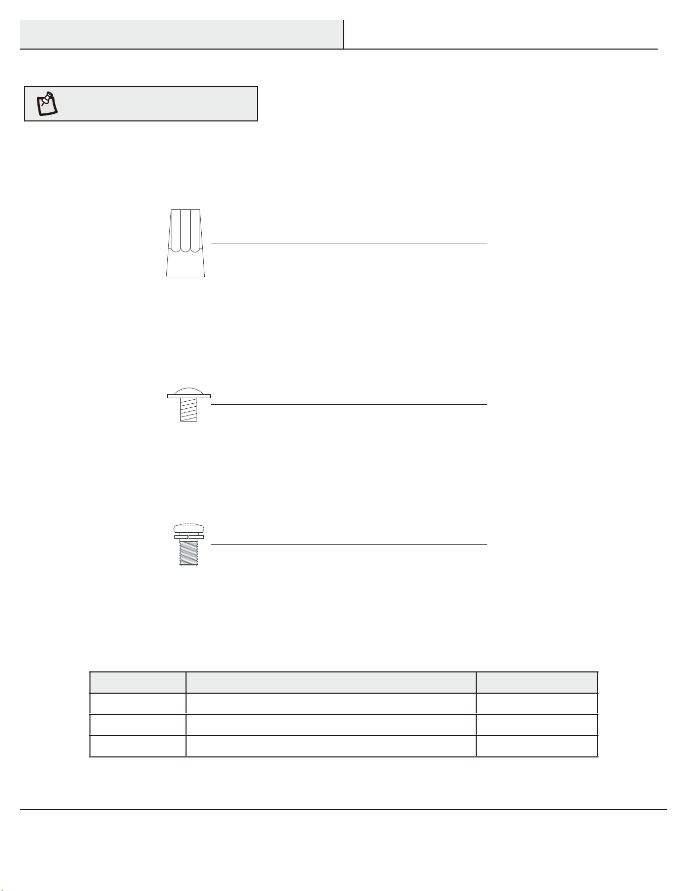
HARDWARE INCLUDED
NOTE: Hardware not shown to actual size.
AA
BB
CC
DD
EE
12
Part
CC
DD
EE
Description
Wire connecting nut
Blade screws
Extra blade bracket screw
Quantity
3
12
1
DD
EE
CC
5
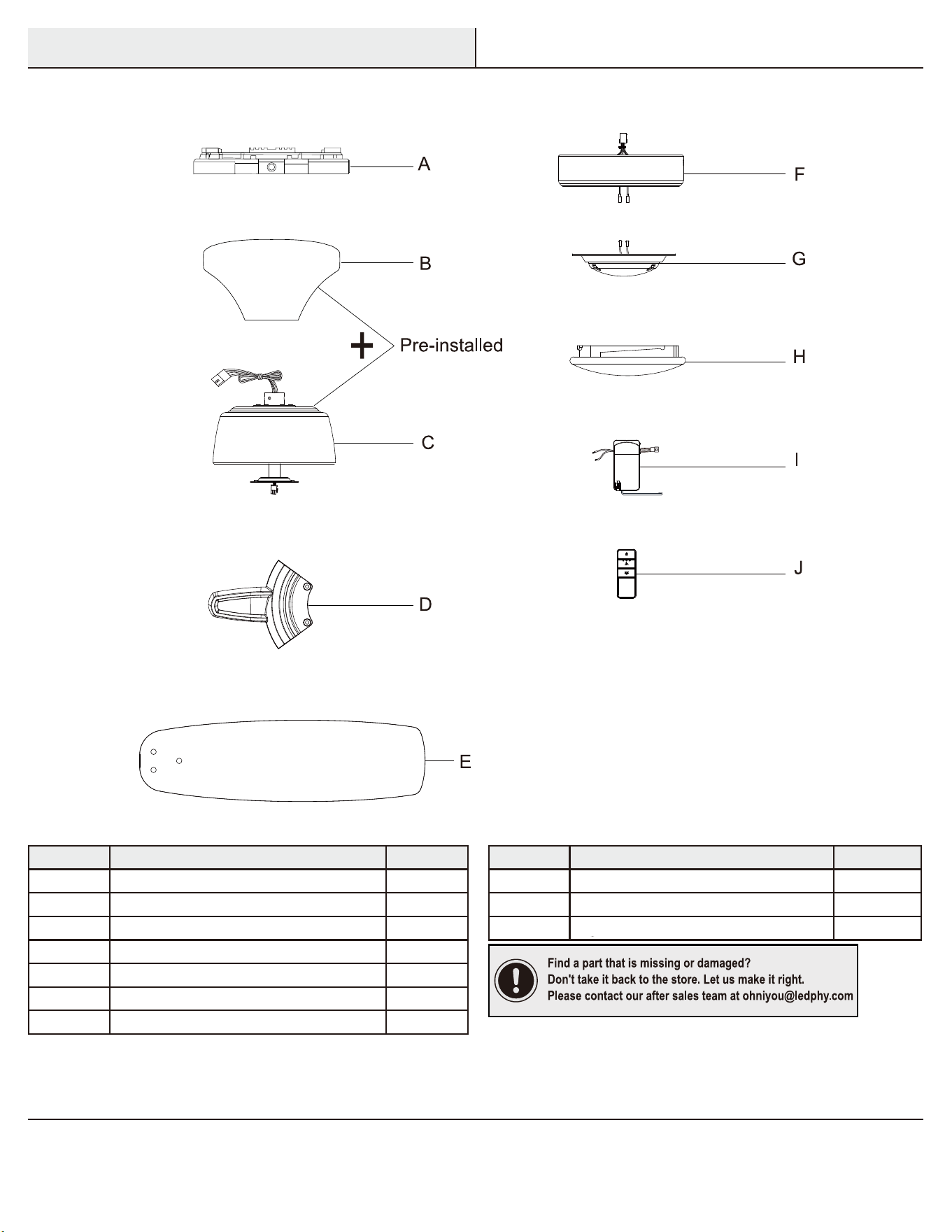
Part Description Quantity
A Slide-on mounting bracket (inside canopy) 1
B Ball/downrod assembly 1
C Canopy 1
D Decorative motor collar cover 1
E Fan-motor assembly 1
F Blade bracket (with pre-installed screws)
4
G Blade
Part Description Quantity
H Light kit pan 1
I Light kit fitter assembly 1
J Glass shade 1
K Receiver 1
L Transmitter 1
4
IMPORTANT
: This product and/or components are
governed by one or more of the following U.S. Patents:
5,947,436; 5,988,580; 6,010,110; 6,046,416, 6,210,117
and other patents pending.
Pre-Installation (continued)
PACKAGE CONTENTS
E
A
B
C
D
G
F
H
J
I
K
L
Ceiling bracket Light cover
Receivers
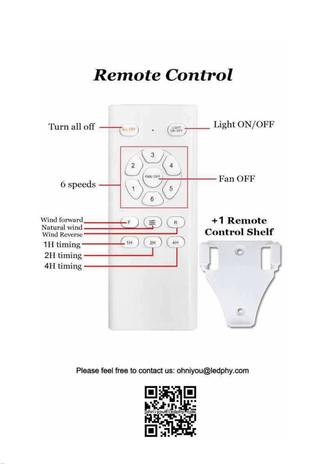
Remote control
Canopy
Motor
Blade bracket(with pre-installed screws)
Blade
Light kit pan
LED assembly
4
4
1
1
6
Installation
MOUNTING OPTIONS
WARNING: To reduce the risk of fire, electric shock
or personal injury, mount to an outlet box marked
“Acceptable for fan support of 35 lbs (15.9 kg) or less,”
and use the screws provided with the outlet box. An
outlet box commonly used for the support of lighting
fixtures may not be acceptable for fan support and may
need to be replaced. If in doubt, consult a qualified
electrician.
If your ceiling fan does not have an existing UL mounting box,
then install one using the following instructions:
Ƒ Disconnect the power by removing the fuses or turning off
the circuit breakers.
Ƒ Secure the outlet box directly to the building structure.
Use the appropriate fasteners and materials. The outlet box
and its bracing must be able to fully support the weight of
the moving fan (at least 35 lbs). Do not use a plastic outlet
box.
The illustrations below show three different ways to mount the
outlet box.
If the canopy (C) touches the ball/downrod assembly (B), then remove
the decorative canopy bottom cover and turn the canopy (C) 180°
before attaching the canopy (C) to the mounting plate.
To hang your fan where there is an existing fixture but no ceiling joist,
you may need an installation hanger bar as shown above (available at
any Home Depot store).
NOTE: You may need a longer downrod to maintain
proper blade clearance when installing on a steep, sloped
ceiling. The maximum angle allowable is 30° away from
horizontal.
Outlet Box
Outlet Box
Recessed
Outlet
Box
Provide Strong
Support
Ceiling
Mounting
Plate
Outlet Box
Hanger Bar
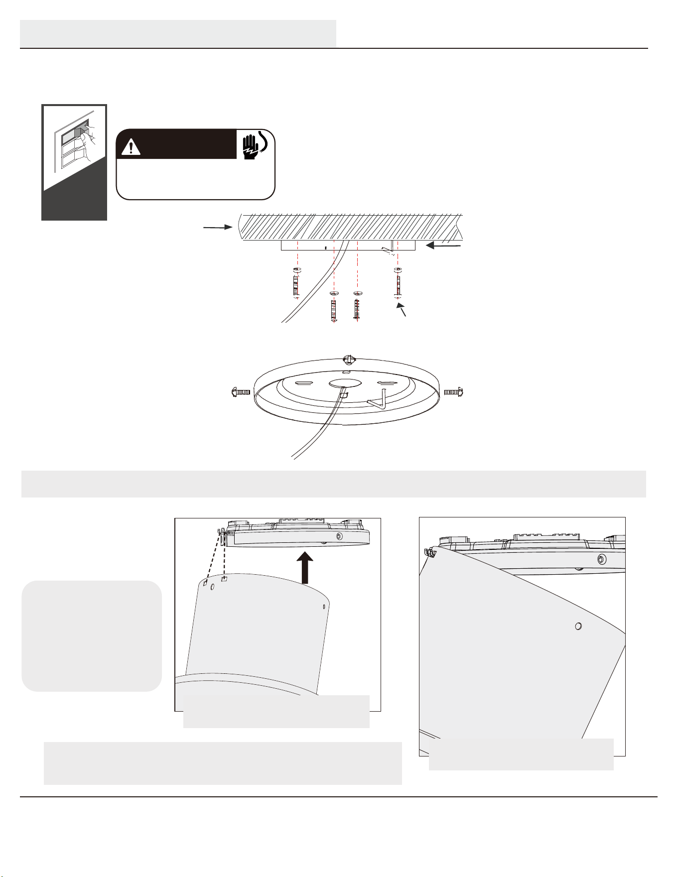
You have two options for installation. Pick whi ch one works best for your location. Remove any existing
bracket prior to installation. Only use the provided ceiling bracket that came in your fan’s box.
Turn Power
OFF
Do this first!
WARNING
To avoid possible electrical shock, before
installing your fan, disconnect the power by
turning off the circuit breakers to the outlet
box associated with the wall switch location
Mounting Bracket
120V Wires
olid Wood
Mounting Bracket
Screws
Ceiling
S
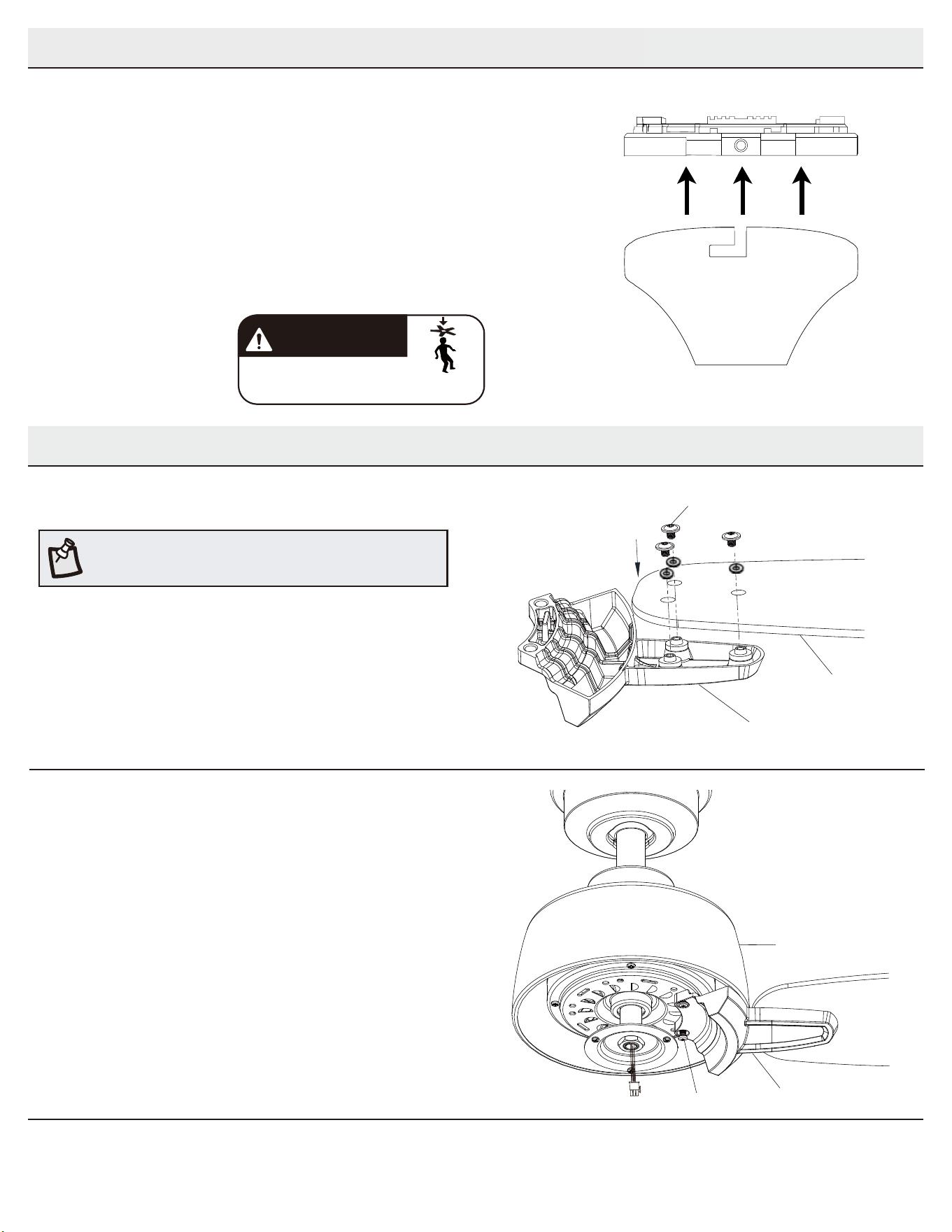
Hanging the Fan
NOTICE
To prevent damage
to fan, ALWAYS lift
holding the fan
housing.
Raise the fan and align the slots in the
canopy with the hooks on the ceiling plate
Place the slots over the ceiling
plate hooks to hang the fan.
Note: To hang the fan, you must tilt the canopy to
an almost vertical position so that the canopy slots
sit on the ceiling plate hooks.
10
Assembly - Hanging the Fan (continued)
5
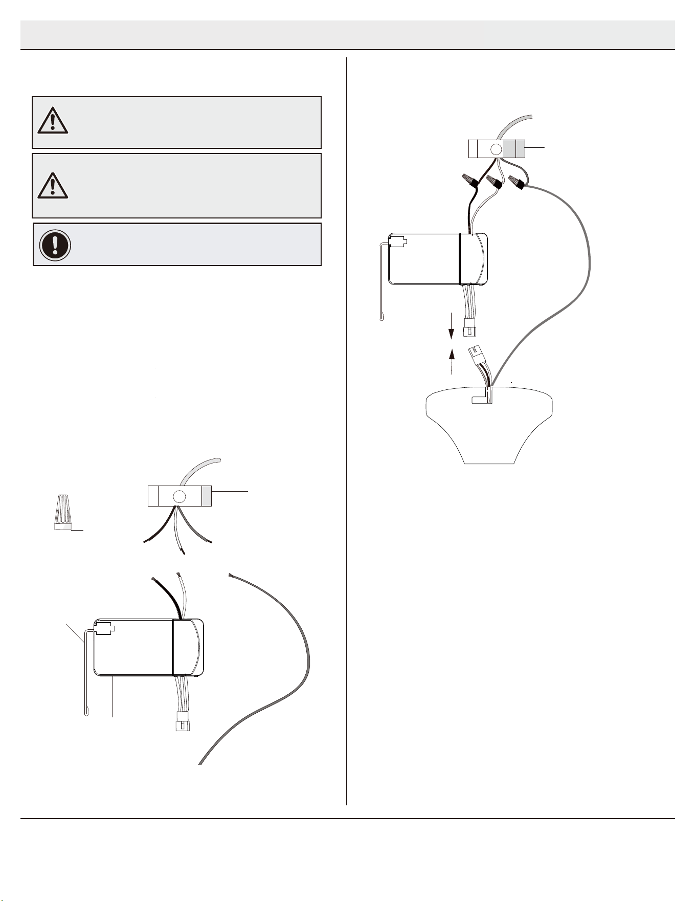
Wiring the receiver to the
household wiring
Ƒ Spread the wires apart so that the green and white wires
are on one side of the outlet box and the black wire is on the
other side.
Ƒ Connect the green fan wires to the household ground wire
(this may be a green or bare wire) using a wire connecting nut
(CC).
Ƒ Connect the receiver (K) black or red wire to the household
black (hot) wire using a wire connecting nut (CC).
Ƒ Connect the receiver (K) white wire to the household white
wire (neutral) using a wire connecting nut (CC).
Ƒ Secure each wire connecting nut using electrical tape.
WARNING: To avoid possible electrical shock, turn the
electricity off at the main fuse box before wiring. If you
feel you do not have enough electrical wiring knowledge or
experience, contact a licensed electrician.
WARNING: Each wire nut supplied with this fan is designed
to accept up to one 12-gauge house wire and two wires
from the fan. If you have larger than 12-gauge house wiring
or more than one house wire to connect to the fan wiring,
consult an electrician for the proper size wire nuts to use.
IMPORTANT: Use the wire connecting nuts (CC) supplied
with your fan. Secure the connectors with electrical tape
and ensure there are no loose strands or connections.
Outlet box
in the ceiling
(SS)
Green
(or Bare)
6
Wiring the fan to the receiver
NOTE: The fan comes with 12 in. lead wires for use with
the provided 4.5 in. ball downrod assembly (B). If you wish
to use longer downrod, you can use the extension lead
wire (42 in.) (M) provided.
Black
Black
Green (or Bare)
Green
(or Bare)
Outlet Box
Receiver
Antenna
White
Receiver (K)
CC (x3)
Ƒ If using the 4.5 in. ball downrod assembly (B) provided,
wire the receiver to the fan wires by connecting the molded
adaptor plug from receiver (K) with molded adaptor of the fan
motor assembly (E) together.
Ƒ If you wish to use longer downrod, you can use the extension
lead wire (42 in.) (M) provided by connecting the molded
adaptor together.
Wiring
1 2
Outlet box
in the ceiling
(SS)
Green
(or Bare)
I
I
I
7
11
Assembly - Attaching the Fan Blades
Mounting the fan-motor assembly
(standard mount)
7
Attaching the blades to the blade
brackets
1
Ƒ Attach a blade (G) to blade bracket (F) by inserting the
screws (DD) into the holes in the blade (G) and through
the blade bracket (F).
Ƒ Tighten each screw securely.
Ƒ Repeat this step for each blade and blade bracket.
Ƒ Align the locking slots of the canopy (C) with the two
screws (HH) and alignment post (KK) in the mounting
bracket (A).
Ƒ Push up the canopy (C) and turn clockwise until the
alignment post (KK) engage to the round hole and the
screws (HH) engage to the key slots.
Ƒ Firmly tighten the two mounting screws (HH).
Ƒ
Fastening the blade assemblies to
the motor
2
Ƒ Fasten the blade/blade bracket assembly to the fan motor
assembly (E) by inserting the alignment posts into the slot on
the bottom of the motor and tightening the pre-installed blade
bracket screws (EE).
Ƒ Repeat this steps for the remaining blades.
NOTE: Your fan blades are reversible. Select the blade side finish
which best accentuates your decor.
F
DD
G
E
F
EE
K
C
A
HH
B
E
D
KK
Assembly - Hanging the Fan (continued)
Installing the Canopy
1. Make sure the wires are connected correctly.
Put the receiver and all the wires into the Canopy.
(Canopy and motor are already pre-connected).
2. Release the hook. Attach the screws of the
vertical ceiling bracket to the grooves of the
Canopy. When finished, rotate the Canopy so
that the screws slide into the grooves.
Tighten the screws.
WARNING
FAN FALL HAZARD Make
sure to secure the canopy
C
D
D
E
Attach a blade (E) to blade bracket (D) by inserting the
screws (DD) into the holes in the blade (E) and through
the blade bracket (D).
Tighten each screw securely.
Repeat this step for each blade and blade bracket.
Fasten the blade/blade bracket assembly to the fan motor
assembly (C) by inserting the alignment posts into the slot on
the bottom of the motor and tightening the pre-installed blade
bracket screws (EE).
Repeat this steps for the remaining blades.
8
12
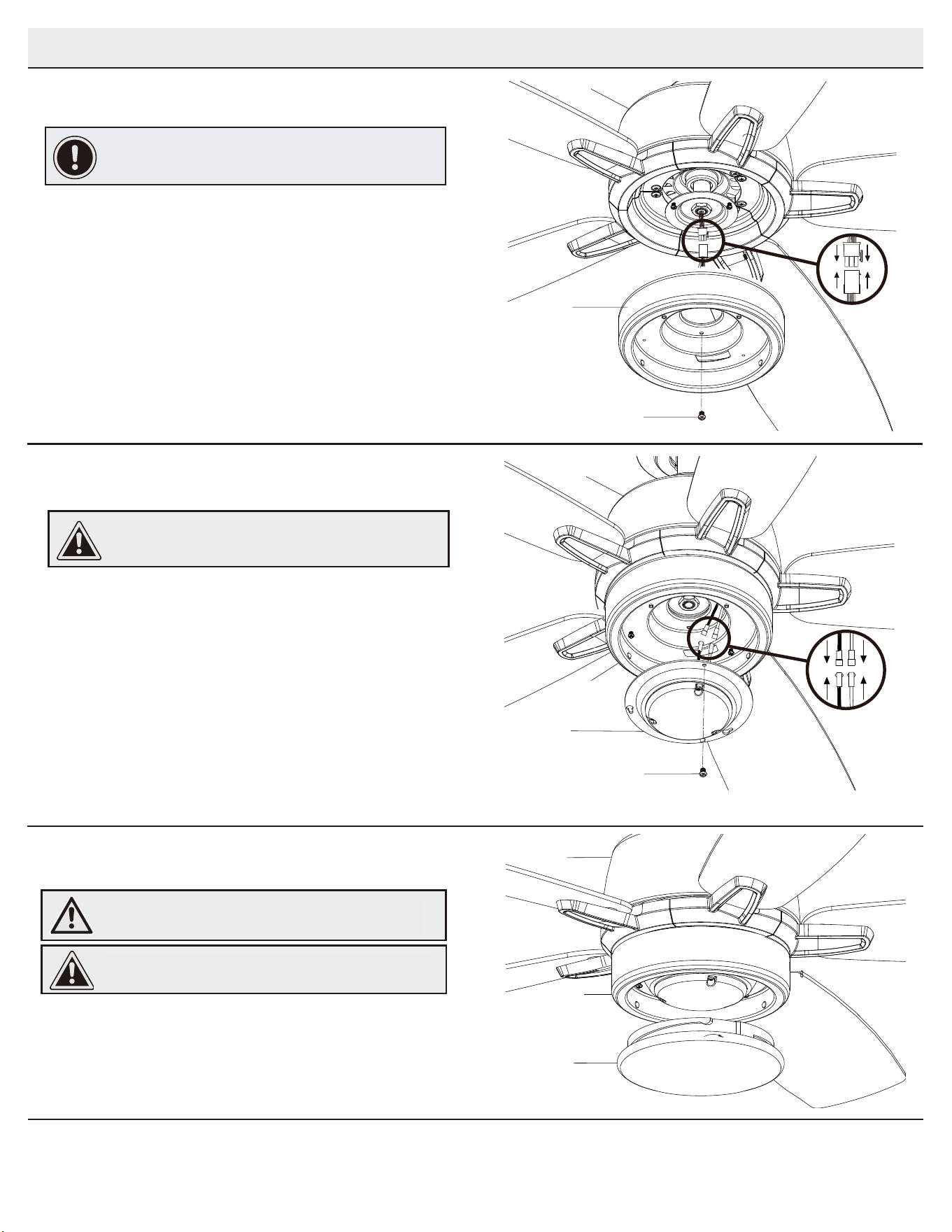
Installing the glass bowl
3
Ƒ Place the glass bowl (J) into the light kit pan (H), aligning the
three flat areas on the top flange of the glass bowl (J) with the
raised dimples in the light kit pan.
Ƒ Turn the glass bowl (J) clockwise until it stops.
CAUTION: Make sure the power is off before attaching or
removing the glass bowl.
WARNING: Allow the glass bowl to cool completely before
removing.
Assembly - Attaching the Lights
Attaching the light kit fitter assembly
2
Ƒ Remove one screw (PP) from the light kit pan (H) and loosen but do
not remove the other two screws.
Ƒ Connect the wires from the light kit fitter assembly (I) to the wires
from the light kit pan (H) by connecting the molded adaptor plugs
together. Carefully tuck all wires and splices into the switch cup.
Ƒ Push the light kit fitter assembly (I) up to the light kit pan (H) so that
the two loosened screw heads fit into the keyhole slots. Turn the light
kit fitter assembly (I) clockwise.
Ƒ Re-install the screw (PP) that was removed in step 1.
Ƒ Make sure all the screws are firmly tightened.
CAUTION: To reduce the risk of electric shock, disconnect
the electrical supply circuit to the fan before installing the
light fixture.
Installing the light kit pan
1
IMPORTANT: It is critical to attach the light kit pan using the
quick connector. The fan will not operate unless the light kit
pan is connected to the fan.
Ƒ Remove one screw (RR) from the black bracket below the fan
motor assembly (E), and loosen but do not remove the other
two screws.
Ƒ Connect the 9-pin plug exiting the bottom of the fan motor
assembly (E) to the 9-pin plug from the light kit pan (H). Be sure
the plug connections snap together completely.
Ƒ Push the light kit pan (H) up to the fan motor assembly (E) so
that the two loosened screw heads fit into the keyhole slots.
Turn the light kit pan (H) clockwise.
Ƒ Re-install the screw (RR) that was removed in step 1.
Ƒ Make sure all the screws are firmly tightened.
RR
H
E
I
E
PP
H
E
J
H
Remove one screw (PP) from the light kit pan (F) and loosen but do
not remove the other two screws.
Connect the wires from the LED assembly(G) to the wires
from the light kit pan (F) by connecting the molded adaptor plugs
together. Carefully tuck all wires and splices into the switch cup.
Push the LED assembly(G) up to the light kit pan (H) so that
the two loosened screw heads fit into the keyhole slots. Turn the
LED assembly(G) clockwise.
Re-install the screw (PP) that was removed in step 1.
Make sure all the screws are firmly tightened.
Attaching the LED assembly
Place the Light cover (H) into the Light kit pan (F), aligning the
three flat areas on the top flange of the Light cover (H) with the
raised dimples in the light kit pan.
Turn the Light cover (H) clockwise until it stops.
Installing the light cover
WARNING: Allow the light cover to cool
completely before removing.
CAUTION: Make sure the power is off before
attaching or removing the light cover.
C
F
C
F
G
C
F
H
Remove one screw (RR) from the black bracket below the fan
motor assembly (C), and loosen but do not remove the other
two screws.
Connect the 9-pin plug exiting the bottom of the fan motor
assembly (C) to the 9-pin plug from the light kit pan (F). Be sure
the plug connections snap together completely.
Push the light kit pan (F) up to the fan motor assembly (C) so
that the two loosened screw heads fit into the keyhole slots.
Turn the light kit pan (F) clockwise.
Re-install the screw (RR) that was removed in step 1.
Make sure all the screws are firmly tightened.
9
13
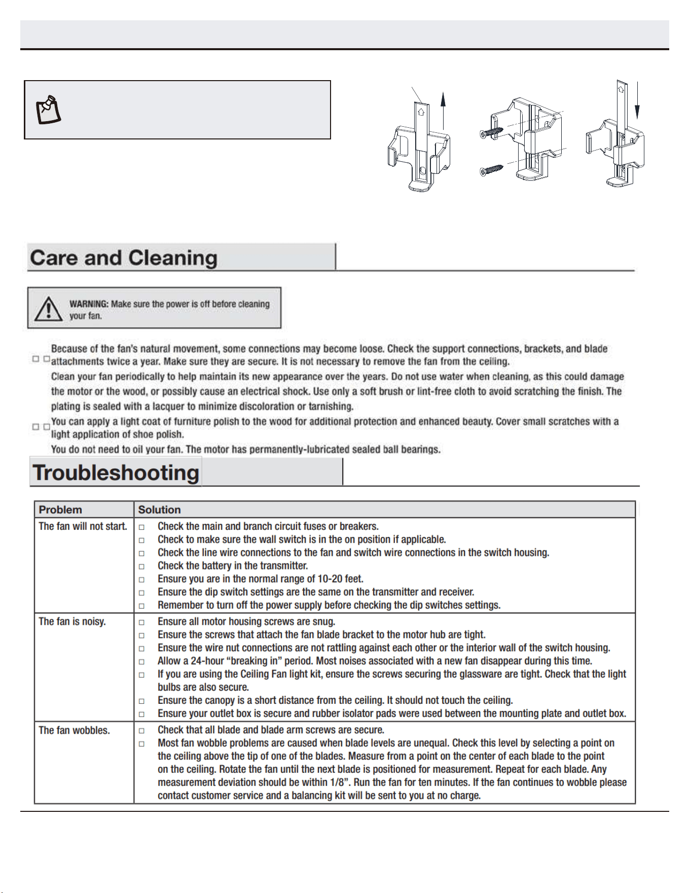
Assembly - Attaching the Accessories
Mounting the remote control holder
Ƒ Slide the screw cover plate up to remove it from the wall
cradle.
Ƒ Position the wall cradle in the desired position and attach it to
the wall using the included wall cradle screws.
Ƒ Slide the screw cover plate back onto the wall cradle to
conceal the screws.
Screw cover plate
NOTE: Screw wall anchors are included for extra support. The
included screws are designed to screw easily into the wall. If
you would like a more permanent or secure hold, install the wall
anchors prior to attaching the wall cradle to the wall.
10
: