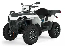
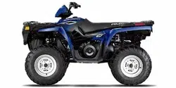
![SPORTSMAN 6X6 570 EPS [TRACTOR T1B] photo](https://manualsfile.com/images/appliances/k4/o4/k4o4cslaydi_0_1720946401_thumbnail.webp)

PMS 419
2025
OWNER’S
MANUAL
Sportsman Touring 570 Tractor / Zugmaschine / MD
Sportsman X2 570 Tractor / MD
Sportsman 6x6 570 Tractor
For Maintenance and Safety
WARNING
Read this manual carefully. It contains important safety
information. This is an adult vehicle only.
Operation is prohibited for those under 16 years of age.
WARNING
Operating, servicing, and maintaining a passenger vehicle or off-road
vehicle can expose you to chemicals including engine exhaust, carbon
monoxide, phthalates, and lead, which are known to the State of California
to cause cancer and birth defects or other reproductive harm. To minimize
exposure, avoid breathing exhaust, do not idle the engine except as
necessary, service your vehicle in a well-ventilated area and wear gloves
or wash your hands frequently when servicing your vehicle.
For more information go to www.P65Warnings.ca.gov/passenger-vehicle.
!
WARNING
Read, understand, and follow all of the instructions and safety
precautions in this manual and on all product labels.
Failure to follow the safety precautions
could result in serious injury or death.
!
For videos and more information
about a safe riding experience with
your Polaris vehicle, scan this QR
Code® with your smartphone or visit:
www.polaris.com/en-us/safety/

2025 Owner’s Manual
Sportsman Touring 570 EPS Tractor
Sportsman Touring 570 EPS SP Tractor
Sportsman Touring 570 EPS Zugmaschine
Sportsman Touring 570 EPS MD
Sportsman X2 570 EPS Tractor
Sportsman X2 570 EPS Nordic Pro Tractor
Sportsman X2 570 EPS LE Black Edition Tractor
Sportsman X2 570 EPS MD
Sportsman 6x6 570 EPS Tractor
Sportsman 6x6 570 EPS Nordic Pro Tractor

BatteryMINDer® is a registered trademark of VDC Electronics, Inc. DEFA
SM
is a service trademark of Defa AS aksjeselskap (as) NORWAY
Blingsmovegen. MacPherson Ride® is a registered trademark of Aftermarket
Auto Parts Alliance, Inc. NGK® is a registered trademark of NGK Spark Plug
Co., Ltd. QR Code® is a registered trademark of DENSO WAVE
INCORPORATED. Tread Lightly
SM
is a service mark of the United States
Department of Agriculture.
Unless noted, trademarks are the property of Polaris Industries Inc.
Copyright 2024 Polaris Industries Inc. All information contained within this
publication is based on the latest product information at the time of
publication. Due to constant improvements in the design and quality of
production components, some minor discrepancies may result between the
actual vehicle and the information presented in this publication. Depictions
and/or procedures in this publication are intended for reference use only. No
liability can be accepted for omissions or inaccuracies. Any reprinting or
reuse of the depictions and/or procedures contained within, whether whole or
in part, is expressly prohibited.
The original instructions for this vehicle are in English. Other languages are
provided as translations of the original instructions.
Printed in Hungary
9941903 R01

Thank you for purchasing a POLARIS vehicle, and welcome to our world-wide
family of POLARIS enthusiasts. Be sure to visit us online at www.polaris.com for
the latest news, new product introductions, upcoming events, career
opportunities and more.
Here at POLARIS we proudly produce an exciting line of utility and recreational
products. We believe POLARIS sets a standard of excellence for all utility and
recreational vehicles manufactured in the world today. Many years of experience
have gone into the engineering, design, and development of your POLARIS
vehicle.
For safe and enjoyable operation of your vehicle, be sure to follow the
instructions and recommendations in this owner’s manual. Your manual contains
instructions for minor maintenance, but information about major repairs is
outlined in the POLARIS Service Manual and can be performed by a POLARIS
dealer.
Your POLARIS dealer knows your vehicle best and is interested in your total
satisfaction. Your POLARIS dealership can perform all of your service needs
during and after the warranty period.
For the most up-to-date owner’s manual visit
https://www.polaris.com/en-us/owners-manuals.
3
WELCOME
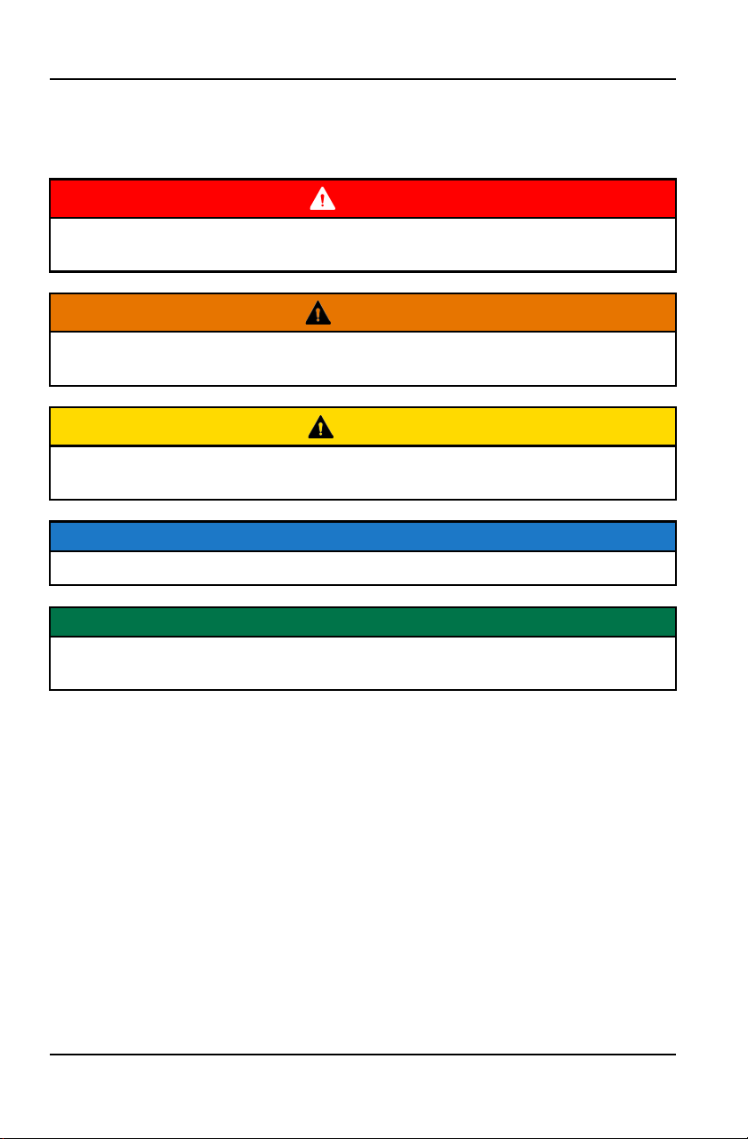
The following signal words and symbols appear throughout this manual and on
your vehicle. Your safety is involved when these words and symbols are used.
Become familiar with their meanings before reading the manual.
DANGER
DANGER indicates a hazardous situation which, if not avoided, WILL result in
death or serious injury.
WARNING
WARNING indicates a hazardous situation which, if not avoided, COULD result
in death or serious injury.
CAUTION
CAUTION indicates a hazardous situation which, if not avoided, COULD result
in minor to moderate injury.
NOTICE
NOTICE provides key information by clarifying instructions.
IMPORTANT
IMPORTANT provides key reminders during disassembly, assembly, and
inspection of components.
The Prohibition Safety Sign indicates an action NOT to take in
order to avoid a hazard.
The Mandatory Action Sign indicates an action that NEEDS to
be taken to avoid a hazard.
4
SAFETY SYMBOLS AND SIGNAL WORDS

Introduction . . . . . . . . . . . . . . . . . . . . 7
Safety . . . . . . . . . . . . . . . . . . . . . . 13
Features and Controls . . . . . . . . . . . . . . 43
Operation . . . . . . . . . . . . . . . . . . . . 91
Winch Guide (If Equipped) . . . . . . . . . . . . 115
Emission Control Systems . . . . . . . . . . . . . 125
Maintenance . . . . . . . . . . . . . . . . . . 127
Specifications . . . . . . . . . . . . . . . . . . 209
POLARIS Products . . . . . . . . . . . . . . . . 217
Troubleshooting . . . . . . . . . . . . . . . . . 219
Warranty . . . . . . . . . . . . . . . . . . . . 235
Maintenance Log . . . . . . . . . . . . . . . . 241
5

6

INTRODUCTION
IMPORTANT WARNING ABOUT THIS MANUAL
WARNING
Failure to heed the warnings and safety precautions contained in this manual
can result in severe injury or death. A POLARIS ATV is not a toy and can be
hazardous to operate. This vehicle handles differently than other vehicles,
such as motorcycles and cars. A collision or rollover can occur quickly, even
during routine maneuvers like turning, or driving on hills or over obstacles, if
you fail to take proper precautions.
• Read this owner’s manual. Understand all safety warnings, precautions and
operating procedures before operating a POLARIS ATV. Keep this manual
with the ATV.
• Never operate an ATV without proper instruction. Take a certified ATV safety
training course. In the United States, certified training can be found at www.
atvsafety.org.
• This vehicle is an ADULT VEHICLE ONLY. Operation is prohibited for
anyone under 16 years of age.
• Never permit a guest to operate the ATV unless the guest has read this
manual and all product labels and has completed a certified safety training
course. In the United States, certified training can be found at www.
atvsafety.org.
7
INTRODUCTION


SECURITY COMPLIANCE STATEMENT
May 7, 2024
Rolle, Switzerland
Polaris Sales Europe Sàrl, declares that the vehicle(s) covered by this Owner
Manual conform to the applicable security requirements in Schedule 2 of UK
PSTI Regulation 2023 No. 1007.
The products will be supported with security updates until December 31, 2028.
This statement of compliance was prepared by Polaris Sales Europe Sàrl.
11
INTRODUCTION

VEHICLE IDENTIFICATION NUMBERS
The vehicle identification number (VIN)
q
is stamped on the upper frame rail on
the front right side (under the seat) on all models.
The engine serial number is located on the front portion of the engine on the
crankcase cover.
Record your vehicle’s identification numbers in the spaces provided. Remove
the spare key and store it in a safe place. An ignition key can be duplicated only
by ordering a POLARIS key blank and mating it with one of your existing keys.
The ignition switch must be replaced if all keys are lost.
NOTICE
Images are for reference only. Your model might differ slightly.
Vehicle Model Number
Frame VIN
q
Engine Serial Number
REPLACEMENT KEYS
A replacement key can be made from the original key.
Key Blank:
P/N 4080125
Rubber Key Cover:
P/N 5458344
12
INTRODUCTION

SAFETY
SAFETY TRAINING
Safety training is a top priority for POLARIS. POLARIS strongly encourages you
and any family members who will be riding this vehicle to take a training course.
For more information about safety, contact an authorized POLARIS dealer or
visit the POLARIS web site at www.polaris.com.
Your POLARIS vehicle is considered an off-road vehicle. Familiarize yourself
with all laws and regulations concerning the operation of this vehicle in your
area.
We strongly advise you to strictly follow the recommended maintenance
program outlined in your owner's manual. This preventive maintenance program
is designed to ensure that all critical components on your vehicle are thoroughly
inspected at specific intervals.
SAFE RIDING GEAR
Always wear helmet, eye protection, gloves,
long-sleeve shirt, long pants, and over-the-ankle
boots at all times. Protective gear reduces the
chance of injury.
q
Helmet
w
Eye Protection
e
Long Sleeves
r
Gloves
t
Long Pants
y
Over-the-Ankle Boots
13
SAFETY

HELMET
Wearing a helmet can prevent a severe head injury. Whenever riding this
POLARIS vehicle, always wear a helmet that meets or exceeds established
safety standards. Clasp the buckle and pull each strap tight to ensure the helmet
is properly secured to the head.
Approved helmets in the USA and Canada bear a
U.S. Department of Transportation (DOT) label.
Approved helmets in Europe, Asia and Oceania
bear the ECE 22.05 (or newer) label. The ECE
mark consists of a circle surrounding the letter E,
followed by the distinguishing number of the
country which has granted approval. The approval
number and serial number will also be displayed
on the label.
EYE PROTECTION
Do not depend on eyeglasses or sunglasses for eye protection. Whenever riding
this POLARIS vehicle, always wear shatterproof goggles or use a shatterproof
helmet face shield. POLARIS recommends wearing approved Personal
Protective Equipment (PPE) bearing markings such as VESC 8, V-8, Z87.1, or
CE. Make sure protective eye wear is kept clean.
GLOVES
Wear gloves for comfort and for protection from sun, cold weather and other
elements.
BOOTS
Wear sturdy over-the-ankle boots for support and protection. Never ride a
POLARIS vehicle with bare feet or sandals.
CLOTHING
Wear long sleeves and long pants to protect arms and legs.
ADDITIONAL PROTECTIVE GEAR
Gear that may be appropriate for your riding conditions.
14
SAFETY

Ear Protection: Long-term exposure to wind and engine noise can cause
permanent hearing loss. Properly worn hearing protective devices such as
earplugs can help prevent hearing loss. Check local laws or the rules of the
riding area you are in before wearing hearing protection to make sure its use is
permitted.
15
SAFETY

SAFETY WARNINGS
WARNING
Failure to operate this vehicle properly can result in a collision, loss of control,
accident or rollover, which may result in serious injury or death. Heed all safety
warnings outlined in this section of the owner’s manual. See the operation
section of this owner’s manual for proper operating procedures.
OPERATING WITHOUT INSTRUCTION
Operating this ATV without proper instruction
increases the risk of an accident. The
operator must understand how to operate the
ATV properly in different situations and on
different types of terrain.
Beginning and inexperienced operators
should complete the recommended safety
training before operating this vehicle.
Never permit a guest to operate the ATV
unless the guest has read this manual and all
product labels and has completed a certified
safety training course.
AGE RESTRICTIONS
This vehicle is an ADULT VEHICLE ONLY.
Operation is prohibited for anyone under 16
years of age.
Never allow anyone under 12 years of age to
ride as a passenger on a 2-up ATV.
Even though a child may be within the
recommended age group for operating some
ATVs, they may not have the skills, abilities,
or judgment needed to operate or ride on this
ATV safely and could be susceptible to
accident or injury.
If you are operating a 2-up ATV, do not carry
passengers whose feet do not reach the
footrests.
16
SAFETY

USING ALCOHOL OR DRUGS
Never consume alcohol or drugs before or
while operating this vehicle.
Operating this vehicle after consuming
alcohol or drugs could adversely affect
operator judgment, reaction time, balance
and perception.
CARRYING MORE THAN ONE
PASSENGER ON A 2-UP ATV
Carrying more than one passenger on a 2-up
ATV greatly reduces the operator's ability to
balance and control the ATV, which may
result in an accident or rollover. Never carry
more than one passenger on a 2-up ATV.
FAILURE TO INSPECT BEFORE OPERATING
WARNING
Failure to inspect and verify that the vehicle is in safe operating condition
before operating increases the risk of an accident.
Always perform the pre-ride inspection before each use of your vehicle to
make sure it's in safe operating condition.
Always follow the inspection and maintenance procedures and schedules
described in this owner’s manual.
17
SAFETY
HANDLING GASOLINE
Gasoline is highly flammable and explosive under certain conditions.
• Always exercise extreme caution whenever handling gasoline.
• Always refuel with the engine stopped, and outdoors or in a well ventilated
area.
• Never carry fuel or other flammable liquids on this vehicle. Failure to follow
this instruction could lead to serious burn injuries or death.
• Do not smoke or allow open flames or sparks in or near the area where
refueling is performed or where gasoline is stored.
• Do not overfill the tank. Do not fill the tank neck.
• If gasoline spills on your skin or clothing, immediately wash it off with soap
and water and change clothing.
EXPOSURE TO EXHAUST
CAUTION
Engine exhaust fumes are poisonous and can cause loss of consciousness or
death in a short time. Never start the engine or let it run in an enclosed area.
Operate this vehicle only outdoors or in well-ventilated areas.
PROTECTIVE APPAREL
Riding in this vehicle without wearing an
approved helmet and protective eye wear
increases the risk of a serious injuries in the
event of an accident.
Always wear a helmet, eye protection,
gloves, long-sleeve shirt, long pants and
over-the-ankle boots.
FORESTRY APPLICATION AND CROP SPRAYING
This vehicle does not have a Falling Objects Protective Structure (FOPS). Do
not use the vehicle in forestry application situations where the risk of falling
objects may be present.
18
SAFETY

This vehicle is not equipped for protection against hazardous substances. It
does not offer any protection against substances which are harmful to health.
Always wear proper personal protective equipment if this vehicle is used for crop
spraying or other applications requiring the use of hazardous substances.
OPERATING ON PUBLIC ROADS (TRACTOR OR
ZUGMASCHINE MODELS ONLY)
This vehicle is approved for on-road use.
OPERATING ON PUBLIC ROADS (MD MODELS
ONLY)
Operating this vehicle on public streets, roads
or highways could result in a collision with
another vehicle. Never operate this vehicle
on any public street, road or highway,
including dirt and gravel roads (unless
designated for off-highway use).
OPERATING ON PAVEMENT
This vehicle’s tires are primarily designed for off-road use. Operating this vehicle
on paved surfaces (including sidewalks, paths, parking lots and driveways) may
adversely affect the handling of the vehicle and may increase the risk of loss of
control and accident or rollover. Avoid operating the vehicle on pavement. If it's
unavoidable, travel slowly, travel short distances and avoid sudden turns or
stops.
19
SAFETY
OPERATING AT EXCESSIVE SPEEDS
Operating this vehicle at excessive speeds
increases the operator's risk of losing control.
Always operate at a speed that's appropriate
for the terrain, the visibility and operating
conditions and your skills and experience.
PHYSICAL CONTROL OF THE VEHICLE
Removing even one hand or foot can reduce ability to control the vehicle or
could cause loss of balance and ejection from the ATV.
If a person's feet are not firmly planted on the footrests, they could come into
contact with the wheels or other moving parts and lead to accident or injury.
Always keep both hands on the handlebars and both feet on the footrests of the
ATV during operation.
TURNING IMPROPERLY
CAUTION
Turning improperly could cause loss of traction, loss of control, accident or
rollover. Always follow proper procedures for turning as described in this
owner’s manual.
Avoid sharp turns. Never turn while applying heavy throttle. Never make abrupt
steering maneuvers. Practice turning at slow speeds before attempting to turn at
faster speeds.
20
SAFETY

JUMPS AND STUNTS
Exhibition driving increases the risk of an
accident or rollover. DO NOT do power
slides, “donuts”, jumps or other driving stunts.
Avoid exhibition driving.
IMPROPER HILL CLIMBING
Improper hill climbing could cause loss of control or rollover. Use extreme
caution when operating on hills. Always follow proper procedures for hill climbing
as described in this owner's manual. See the New Operator Driving Procedures
section for details.
DESCENDING HILLS IMPROPERLY
Improperly descending a hill could cause loss of control or rollover. Always
follow proper procedures for traveling down hills as described in this owner’s
manual. See the New Operator Driving Procedures section for details.
CROSSING HILLSIDES
Driving on a sidehill is not recommended. Improper procedure could cause loss
of control or rollover. Avoid crossing the side of any hill unless absolutely
necessary.
If crossing a hillside is unavoidable, always follow proper procedures as
described in this owner's manual. See the New Operator Driving Procedures
section for details.
21
SAFETY

STALLING WHILE CLIMBING A HILL
Stalling, rolling backwards or improperly
dismounting while climbing a hill could cause
a rollover.
• Always maintain a steady speed when
climbing a hill.
• Always engage ADC mode (if equipped)
before ascending or descending a hill. If
ADC mode is not equipped, apply AWD
mode before ascending or descending a
hill.
If all forward speed is lost:
• Lean forward to keep body weight uphill. A passenger should also lean uphill.
• Apply the brakes.
• Lock the temporary brake lock when fully stopped.
• Dismount on the uphill side of the vehicle, or on the left if the vehicle is
pointing straight uphill. Have a passenger dismount first, then the operator
may dismount.
• Turn the ATV around and remount, following the procedure described in the
owner's manual.
If the ATV begins rolling downhill:
• Keep operator and passenger body weight uphill.
• Never apply engine power.
• Apply the brake lever gradually.
• When fully stopped, apply the auxiliary brake as well, and then lock the
temporary brake lock.
• Dismount on the uphill side of the vehicle, or on the left if the vehicle is
pointing straight uphill. Have a passenger dismount first, then the operator
may dismount.
• Turn the ATV around and remount, following the procedure described in the
owner's manual.
22
SAFETY

OPERATING ON STEEP HILLS
Operating on excessively steep hills could
cause an overturn.
Never operate on hills too steep for the ATV
or for your abilities.
Never operate this ATV on hills steeper than
15 degrees.
OPERATING ON SLIPPERY TERRAIN
Failure to use extra caution when operating
on excessively rough, slippery or loose
terrain could cause loss of traction, loss of
control, accident or overturn.
Do not operate on excessively rough, slippery
or loose terrain until you've learned and
practiced the skills necessary to control the
vehicle on such terrain.
Always use extra caution on rough, slippery
or loose terrain.
OPERATING IN UNFAMILIAR TERRAIN
Failure to use extra caution when operating on unfamiliar terrain could result in
an accident or rollover.
Unfamiliar terrain may contain hidden rocks, bumps, or holes that could cause
loss of control or rollover.
Travel slowly and use extra caution when operating on unfamiliar terrain. Always
be alert to changing terrain conditions.
23
SAFETY

IMPROPER TIRE MAINTENANCE
Operating this vehicle with improper tires or
with improper or uneven tire pressure could
cause loss of control or accident.
Always use the size and type of tires
specified for your vehicle.
Always maintain proper tire pressure as
described in the owner's manual and on
safety labels.
OPERATING IMPROPERLY IN REVERSE
Improperly operating in reverse could result in a collision with an obstacle or
person. Always follow proper operating procedures as outlined in this manual.
See the New Operator Driving Procedures section for details.
Before shifting into reverse gear, always check for obstacles or people behind
the vehicle. When it's safe to proceed, back slowly.
OPERATING OVER OBSTACLES
Improperly operating over obstacles could
cause loss of control or rollover.
Before operating in a new area, check for
obstacles. Avoid operating over large
obstacles such as large rocks and fallen
trees. Always follow the proper procedures
outlined in this manual when operating over
obstacles. See the New Operator Driving
Procedures section for details.
24
SAFETY
SKIDDING OR SLIDING
Failure to use extra caution when operating
on excessively rough, slippery or loose
terrain could cause loss of traction, loss of
control, accident or rollover. Do not operate
on excessively slippery surfaces. Always
slow down and use additional caution when
operating on slippery surfaces.
Skidding or sliding due to loss of traction can
cause loss of control or rollover (if tires regain
traction unexpectedly). Always follow proper
procedures for operating on slippery surfaces
as described in this owner's manual. See the
New Operator Driving Procedures section for
details.
OPERATING A DAMAGED VEHICLE
CAUTION
Operating a damaged vehicle can result in an accident. After any rollover or
other accident, have a qualified service dealer inspect the entire machine for
possible damage, including (but not limited to) brakes, throttle, and steering
systems.
OPERATING THROUGH WATER
Operating through deep or fast-flowing water can cause loss of traction, loss of
control, rollover or accident. Never operate in fast-flowing water or in water that
exceeds the floor level of the vehicle.
Always follow proper procedures for operating in water as described in this
owner’s manual.
Wet brakes may have reduced stopping ability. After leaving water, test the
brakes. Apply them lightly several times while driving slowly. The friction will help
dry out the pads.
OPERATING IN LIGHTNING
Avoid operating this vehicle when lightning could occur unless the vehicle is
equipped with a fully enclosed cab. Rubber tires, rubber handgrips and a foam
seat will not protect a rider from lightning strikes. Always seek safe shelter when
lightning is imminent.
25
SAFETY
IMPROPER CARGO LOADING
Overloading the vehicle or carrying cargo improperly may cause changes in
stability and handling, which could cause loss of control or an accident.
• Always follow the instructions in this owner’s manual for carrying cargo.
• Never exceed the stated load capacity for this vehicle.
• Cargo should be properly distributed and securely attached.
• Reduce speed when carrying cargo or pulling a trailer. Allow a greater
distance for braking.
OPERATING ON FROZEN BODIES OF WATER
Severe injury or death can result if the vehicle and/or the operator fall through
the ice. Never operate the vehicle on a frozen body of water unless you have
first verified that the ice is sufficiently thick to support the weight and moving
force of the vehicle, you and your cargo, together with any other vehicles in your
party.
Always check with local authorities and residents to confirm ice conditions and
thickness over your entire route. Vehicle operators assume all risk associated
with ice conditions on frozen bodies of water.
POOR VISIBILITY
CAUTION
Operating this vehicle in darkness or inclement weather could result in a
collision or accident, especially if operating on a road or street. Use caution
and drive at reduced speeds in conditions of reduced visibility such as fog, rain
and darkness. Clean headlights frequently and replace burned out headlamps
promptly.
PHYSICAL SKILLS
Safe operation of this rider-active vehicle requires good judgment and physical
skills. Persons with cognitive or physical disabilities who operate this vehicle
have an increased risk of overturn and loss of control.
26
SAFETY
HOT EXHAUST SYSTEMS
WARNING
Exhaust system components are very hot during and after use of the vehicle.
Hot components can cause burns and fire. Do not touch hot exhaust system
components. Always keep combustible materials away from the exhaust
system.
Use caution when traveling through tall grass, especially dry grass and when
traveling through muddy conditions. Always inspect the underside of the
vehicle and areas near the exhaust system after driving through tall grass,
weeds, brush, other tall ground cover, and muddy conditions. Promptly remove
any grass, debris or foreign matter clinging to the vehicle and pay particular
attention to the exhaust system area.
TRAILER HITCH WARNING (IF EQUIPPED)
If using a hitch, ensure the receiver does not exceed a two inch drop or raise.
WARNING
When trailering with your ATV, be aware that the exhaust is located above the
hitch ball receiver and the trailer hitch. During operation of the ATV, the
exhaust will produce hot exhaust gas that should not be inhaled and that may
elevate the surface temperature of surrounding surfaces, including trailer
surfaces (e.g., trailer hitch, trailer tongue, trailer walls, . . . etc.). To reduce the
risk of inhaling exhaust gases and to avoid risk of burn or injury, shut off your
engine and allow time for the exhaust gases to dissipate and for the surfaces
surrounding the exhaust to cool, including the trailer surfaces, before
connecting or disconnecting a trailer. To reduce the potential for the trailer hitch
or trailer tongue from getting too hot, do not use a receiver hitch with a rise of
more than two inches.
UNAUTHORIZED USE OF THE VEHICLE
Leaving the keys in the ignition can lead to unauthorized use of the vehicle by
someone under the age of 16, without a drivers license, or without proper
training. This could result in an accident or rollover. Always remove the ignition
key when the vehicle is not in use.
27
SAFETY

EQUIPMENT MODIFICATIONS
Your POLARIS vehicle is designed to provide safe operation when used as
directed. Modifications to your vehicle may negatively impact vehicle stability.
Failure of critical machine components may result from operation with any
modifications, especially those that increase speed or power. This vehicle may
become less stable at speeds higher than those for which it is designed. Loss of
control may occur at higher speeds.
Do not install any non-POLARIS-approved accessory or modify the vehicle for
the purpose of increasing speed or power. Any modifications or installation of
non-POLARIS-approved accessories could create a substantial safety hazard
and increase the risk of bodily injury.
The POLARIS limited warranty on your POLARIS vehicle will be terminated if
any non-POLARIS approved equipment and/or modifications have been added
to the vehicle that increase speed or power.
The addition of certain accessories, including (but not limited to) mowers,
blades, tires, sprayers, or large racks, may change the handling characteristics
of the vehicle. Use only POLARIS-approved accessories, and familiarize
yourself with their function and effect on the vehicle.
For more information about ATV safety, see the Safety Training section.
28
SAFETY

SAFETY LABELS AND LOCATIONS
Warning labels have been placed on the vehicle for your protection. Read and
follow the instructions on each label carefully. If any of the labels shown in this
manual differ from the labels on your vehicle, always read and follow the
instructions of the labels on the vehicle.
If an informational or graphic label becomes illegible or comes off, contact your
POLARIS dealer to purchase a replacement. Replacement safety labels are
provided by POLARIS at no charge. The part number is printed on the label.
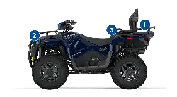
SPORTSMAN TOURING 570
SPORTSMAN TOURING 570 TRACTOR
q
Rack Alert (Front)
w
Rack Alert (Rear)
e
Discretionary Alert
r
Greasing Point Alert
t
Jacking Points Alert
y
4x4 (AWD) Alert
u
Override Alert
i
General Alert
o
Tire Pressure Alert
a
Clutch Cover Alert
s
Fuel Alert
29
SAFETY


GENERAL ALERT — TRACTOR & ZUGMASCHINE
MODELS
WARNING
Before you operate this vehicle,
read the owner’s manual. Never
allow anyone under 16 years of
age to operate this vehicle.
Always wear an approved
helmet, goggles, and protective
clothing. Never use alcohol or
drugs before or while operating.
Never carry more than one
passenger. This vehicle is
approved for on-road use.
Part Number: 7181540
GENERAL ALERT — MD MODELS
WARNING
Before you operate this vehicle,
read the owner’s manual. Never
allow anyone under 16 years of
age to operate this vehicle.
Always wear an approved
helmet, goggles, and protective
clothing. Never use alcohol or
drugs before or while operating.
Never carry more than one
passenger. Never operate the
vehicle on any public street,
road or highway.
Part Number: 7181538
JACKING POINTS ALERT
WARNING
See Elevating the Vehicle for
Service for details.
Part Number: 7184992
35
SAFETY

GREASING POINT ALERT
WARNING
Always read and understand
your owner’s manual.
Lubricate as recommended.
Part Number: 7300027
FUEL ALERT
Compatible Fuel Types:
• E5
• E10
Part Number: 7300053
OVERRIDE ALERT
WARNING
Improper use of override button can lead to loss of
control resulting in severe injury or death. Do not
activate override while throttle is engaged. Always
apply throttle gradually while in reverse.
Part Number: 7181544
36
SAFETY

DISCRETIONARY ALERT
WARNING
Read and understand your
owner’s manual. Never operate
this vehicle on hills steeper than
15°.
Part Number: 7181536
4X4 (AWD) ALERT
WARNING
Do not push switch to engage 4X4 (AWD) if the rear
wheels are spinning. This may cause severe drive
shaft and clutch damage.
Part Number: 7181543
CLUTCH COVER ALERT
WARNING
Keep body parts away from belt.
Part Number: 7181427
37
SAFETY

FUEL TRANSPORT WARNING
WARNING
NEVER carry fuel or other flammable liquids on this
vehicle.
Failure to follow this instruction could lead to serious
burn injuries or death.
Part Number: 7301043
RACK ALERT — TOURING MODELS
WARNING
Do not tow from rack or bumper.
Vehicle damage or tipover may
result causing severe injury or
death. Tow only from tow hooks
or hitch.
Maximum Rack Loads: Front 41
kg. Rear 82 kg.
Part Number: 7181584
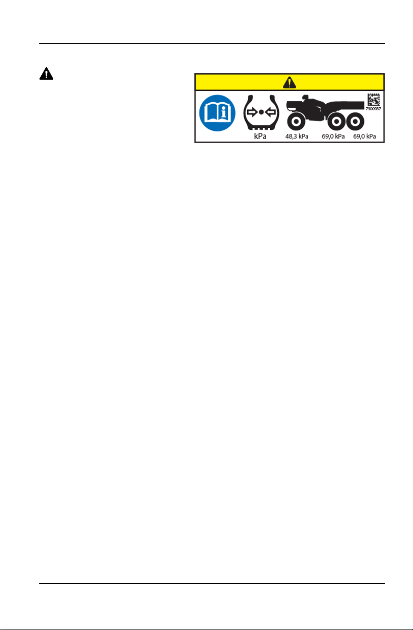
TIRE PRESSURE ALERT — TOURING & X2 MODELS
WARNING
Tire Pressure in kPa:
Front – 48,3 kPa
Rear – 48,3 kPa
Part Number: 7183263
HITCH CAPACITY ALERT — MD MODELS
WARNING
Maximum Drawbar Pull:
3700 N on level ground
Maximum Vertical Load:
1400 N
Part Number: 7300331
38
SAFETY
RADIATOR CAP WARNING — MD MODELS
WARNING
Hot pressurized fluid can cause serious burns. Do not
touch radiator cap when hot. Open slowly.
Part Number: 7300767
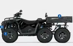
CRUSH ALERTS — X2 & 6X6 MODELS
WARNING
To prevent a crushing injury to hands and fingers, keep
hands and fingers away from the lower front edge of
the cargo box while lowering the box.
Part Number: 7184130
RACK ALERT — X2 & 6X6 MODELS
WARNING
Do not tow from rack or bumper.
Vehicle damage or tipover may
result causing severe injury or
death. Tow only from tow hooks
or hitch.
Maximum Rack Loads: Front 41
kg
Part Number: 7182351
39
SAFETY

BOX ALERT — X2 MODELS
WARNING
Never carry passengers in the cargo box. Passengers can be thrown off. This
can cause serious injury or death.
Maximum Box Load: 181 kg
Part Number: 7301041
BRAKE FLUID FILLING PORT — 6X6 MODELS
WARNING
Brake fluid filling port. Use DOT
4 brake fluid only.
Part Number: 7300029
BOX ALERT — 6X6 MODELS
WARNING
Never carry passengers in the cargo box. Passengers can be thrown off. This
can cause serious injury or death.
Maximum Box Load: 362 kg
Part Number: 7301042
40
SAFETY

42

FEATURES AND CONTROLS
OVERVIEW
NOTICE
Image is for reference only. Your model might differ slightly.
q
Brake Lever
w
Left Hand Controls
e
Drive Mode Switch (if equipped)
r
Work Light Switch (if equipped)
t
Digital Display
y
Hand Warmer Switch (if
equipped)
u
Thumb Warmer Switch (if equipped)
i
AWD Momentary Switch
o
Throttle Lever
a
Ignition Switch
s
Battery Charge Port
d
Auxiliary Outlet
43
FEATURES AND CONTROLS
IGNITION SWITCH
WARNING
Do not attach a large key fob or key ring to the main switch. It may contact the
gas tank cap when turning, causing an interruption to the electrical system and
an unexpected engine shut-down during operation. This could result in serious
injury or death.
SWITCH
POSITION
FUNCTION
End all electrical power to the vehicle
The LIGHTS ON position turns the headlights on. The
engine stop switch must be in the RUN position.
Start the engine. The headlights are not on in this position.
After starting the engine, release the key switch to the
PARKING LIGHTS ON position. The parking lights and
taillights are on in this position.
44
FEATURES AND CONTROLS


ENGINE STOP SWITCH
NOTICE
The engine will not start or run when the switch is in the OFF position.
Push the stop switch down to stop the engine quickly. Pull the stop switch up to
the RUN position before attempting to start the engine.
Both the main switch and the engine stop switch will shut off all electrical power
to the vehicle, including lights.
SWITCH
POSITION
FUNCTION
OFF
RUN
HAZARD WARNING SWITCH
Push the hazard warning switch to cause all turn signal lights to flash
simultaneously. Use this feature to alert others of an emergency or other
situation requiring caution.
HORN SWITCH
Press the horn switch to sound the horn.
46
FEATURES AND CONTROLS
MODE / REVERSE OVERRIDE SWITCH
This vehicle is equipped with a reverse speed limiter system. To gain additional
wheel speed while backing, release the throttle and depress the override switch.
WARNING
Pressing the override switch while the throttle is open can cause loss of
control, which may result in serious injury or death. Always release the throttle
before pressing the override switch.
The reverse override switch also acts as a MODE button when held down for
approximately one half second. The transmission cannot be in reverse when
using the override switch as a MODE button.
TURN SIGNAL SWITCH
Push the toggle switch either left or right to activate the corresponding turn
signal light. The indicator in the gauge will also flash. Return the toggle to the
center position and push it inward to end the signal.
HEADLIGHT AND MOMENTARY HIGH BEAM
SWITCH
The lights do not operate unless the main key switch is on and the engine stop
switch is in the RUN position.
SWITCH
POSITION
FUNCTION
High Beam
Low Beam
Press this switch with your left forefinger to activate the headlight high beam.
The lights will return to low beam when the switch is released.
47
FEATURES AND CONTROLS
RIGHT-HAND CONTROLS
THROTTLE LEVER
WARNING
Operating an ATV with sticking or improperly operating throttle controls could
cause an accident. Never start or operate an ATV that has a sticking or
improperly operating throttle. Immediately contact your POLARIS dealer or
other qualified person for service if throttle problems arise.
Failure to check or maintain proper operation of the throttle system can result
in an accident if the throttle lever sticks during operation. Always check the
lever for free movement and return before starting the engine. Also check
occasionally during operation.
Engine speed and vehicle movement
are controlled by pressing the throttle
lever
q
. The throttle lever is spring
loaded. Engine speed returns to idle
when the lever is released.
WARNING
Modifications to the electronic throttle control could result in failure to perform
as designed, which could result in an accident. Do not attempt to modify the
throttle control system or replace it with any after market throttle mechanisms.
THROTTLE BRAKE OVERRIDE
This ATV is designed to prevent riders from a stuck or unintentional throttle. If
the throttle is engaged and the system detects pressure on the brakes, power
will be limited to the vehicle and a scrolling message will appear on the gauge:
“RELEASE BRAKES”.
In the event of this message, do the following:
1. Release throttle and bring vehicle to a full stop.
2. Check the throttle and brakes to ensure proper functionality. Make sure the
temporary brake lock is unlocked.
Once brakes and throttle are disengaged, the message will clear and the
fault will be saved in the historic code.
48
FEATURES AND CONTROLS

AWD MOMENTARY SWITCH
The All Wheel Drive (AWD) system is
controlled by the AWD Momentary
Switch
w
. Use this switch to engage
TURF mode (if equipped), 2x4, AWD, or
ADC. The vehicle automatically
engages AWD when operating in
forward or reverse if the switch is set to
AWD. For more information, see page
82.
DRIVE MODE SWITCH (IF EQUIPPED)
The Drive Mode Switch has three positions:
• Performance (PERF)
• Standard (STND)
• Work (WORK)
Always use low gear for any of the following conditions
regardless of the selected throttle control setting.
• Operating in rough terrain or over obstacles.
• Loading the vehicle onto a trailer.
• Towing heavy loads.
• Driving frequently at low RPM or at ground speeds below
7 MPH (11 km/h).
PERFORMANCE MODE
Offers a more aggressive feel to the power of the vehicle. Vehicle will accelerate
harder with less throttle movement.
WORK MODE
Throttle is smoother than standard mode. Best for when the operator wants
more precision over vehicle acceleration. This drive mode is recommended to
be used when backing up with a trailer, driving over rough terrain, or loading
vehicle on a trailer.
STANDARD MODE
Use for majority of driving.
49
FEATURES AND CONTROLS

BRAKES
BRAKE LEVER
WARNING
Operating the ATV with a spongy brake lever can result in loss of braking,
which could cause an accident. Never operate the ATV with a spongy-feeling
brake lever. Always contact your dealer for service before operating the
vehicle.
Squeeze the brake lever
q
toward the handlebar to apply
the front and rear brakes. These
brakes are hydraulically
activated disc type brakes that
are activated by only one lever.
Always test brake lever travel
and master cylinder fluid level
before riding. When squeezed,
the lever should feel firm.
Any sponginess would indicate a possible fluid leak or low master cylinder fluid
level, which must be corrected before riding. Contact your POLARIS dealer or
other qualified service facility for proper diagnosis and repairs.
50
FEATURES AND CONTROLS

MASTER CYLINDER/BRAKE FLUID
WARNING
An over-full master cylinder may cause brake drag or brake lock-up, which
could result in an accident. Maintain brake fluid at the recommended level. Do
not overfill.
Check the brake fluid in the
master cylinder before each ride.
1. Position the ATV on a level
surface.
2. Position the handlebars so
the master cylinder
w
is
level.
3. View the brake fluid level through the indicator window
e
on the side of the
master cylinder. The window will appear dark when the fluid level is at MAX.
When fluid level is at the MIN mark, only the lower half of the indicator will be
dark. If the entire indicator window is clear, the master cylinder is empty of
fluid.
4. If fluid level is below the MIN mark, remove the cover screws and add fluid to
the fill line. Do not overfill. Use DOT 4 brake fluid only.
IMPORTANT
Operating the ATV with brake fluid levels below the MIN mark may cause poor
braking performance. If fluid levels are consistently low, it could indicate a leak
somewhere in the brake system. Always ensure the master cylinder reservoir
has the recommended amount of brake fluid. Do not operate if brake fluid is
below the MIN line.
5. Reinstall the cover. Torque screws to specification.
TORQUE
Brake Fluid Cover Screws
17.7 in-lbs (2 N·m)
51
FEATURES AND CONTROLS
WARNING
Never store or use a partial bottle of brake fluid. Brake fluid is hygroscopic,
meaning it rapidly absorbs moisture from the air. The moisture causes the
boiling temperature of the brake fluid to drop, which can lead to early brake
fade and the possibility of brake failure, which could result in an accident. After
opening a bottle of brake fluid, always discard any unused portion.
TEMPORARY BRAKE LOCK
WARNING
Operating the ATV while the temporary brake lock is engaged could result in
an accident or fire. Always make sure the lock is disengaged before operating.
To engage the temporary brake lock, do the following:
1. Place the transmission in
PARK.
2. Squeeze and release the
brake lever two or three
times, then squeeze and
hold.
3. Push the temporary brake
lock
r
forward to engage the
lock.
4. Release the brake lever.
5. To release the temporary brake lock, squeeze and release the brake lever. It
will return to its unlocked position.
WARNING
The temporary brake lock may relax if left on for a long period of time. Always
block the wheels to prevent rolling. Always block the wheels on the downhill
side of the ATV if leaving it parked on a hill. Another option is to park the ATV in
a sidehill position. Never depend on the temporary brake lock alone if the ATV
is parked on a hill.
52
FEATURES AND CONTROLS

AUXILIARY FOOT BRAKE
WARNING
Never back down a hill. Applying the auxiliary brake when backing down a hill
may cause rear tipover, which could result in serious injury or death.
Use caution when applying the auxiliary brake. Do not aggressively apply the
auxiliary brake when going forward. The rear wheels may skid and slide
sideways, causing loss of control and serious injury or death.
NOTICE
Image is for reference only. Your model might differ slightly.
The auxiliary brake system is intended to be used as a backup for the main
brake system. Should the main system fail, use the auxiliary foot brake
q
.
The auxiliary foot brake is located on the inside of the right footrest. Operate this
brake with your right foot. If the rear wheels slide while using the auxiliary brake,
reduce brake pedal pressure to brake the rear wheels without skidding.
53
FEATURES AND CONTROLS

BRAKE FLUID LEVEL
Check the brake fluid level frequently for the auxiliary brake system. The
reservoir is located on the frame and can be accessed through the front right
wheel well.
Maintain the fluid level between the maximum and minimum marks. Use DOT 4
brake fluid only.
NOTICE
Image is for reference only. Your model might differ slightly.
STUCK BRAKE
This ATV is designed to prevent riders from driving through their brakes or
overheating the brake system in the event of a stuck brake. If the brakes are
engaged and the system detects pressure on the throttle, power will be limited to
the vehicle and a scrolling message will appear on the gauge: “RELEASE
BRAKES”.
In the event of this message, do the following:
1. Bring vehicle to a full stop.
2. Check the brakes to make sure the brake lever is not stuck and the
temporary brake lock is unlocked.
3. Once brakes are disengaged, the message will clear and the fault will be
saved in the historic code.
54
FEATURES AND CONTROLS

AUTOMATIC TRANSMISSION GEAR SELECTOR
The transmission gear selector is located on the right side of the vehicle.
H: High Gear
L: Low Gear
N: Neutral
R: Reverse
P: Park
To shift gears, brake to a complete stop.
When the engine is idling, move the
lever to the desired gear.
NOTICE
Shifting gears with the engine speed above idle or while the vehicle is moving
could cause transmission damage.
Whenever the ATV is left unattended, always place the transmission in PARK.
NOTICE
To extend belt life, use low forward gear when pulling a heavy load and when
operating uphill at a slow speed.
55
FEATURES AND CONTROLS

PASSENGER SEAT (X2 MODELS)
Always make sure the passenger seat lock-out is functioning properly before
operating with a passenger.
Do not operate the vehicle with the seat in the 2-up position when operating
without a passenger. Always return the seat to the 1-up position for single-rider
operation.
Never carry cargo in the rear box when operating the ATV in the 2-up mode with
a passenger.
SEAT CONVERSION (X2 MODELS)
NOTICE
The rear seat can be adjusted to three different positions.
1. Make sure the cargo box is securely latched.
2. Slide the seat latch levers
q
inward to release the locks.
3. Tilt the backrest slightly forward.
56
FEATURES AND CONTROLS


5. Lift the adjustment latch
w
at the top of the passenger backrest. Raise the
backrest to the desired position. Release the latch, making sure it locks into
one of the three operating positions.
TIP
The backrest must be moved out of the lowest position before it can be
secured in the upright position. The lowest position is for seat storage only. Do
not leave the backrest in the lowest position. Always adjust the backrest to one
of the three operating positions.
58
FEATURES AND CONTROLS

6. Lower the operator backrest to create the passenger seat. Two retaining pins
under the seat should fit into the two grommets on the seat base.
7. Test the passenger seat lockout by attempting to release the cargo box dump
latch. If the dump latch releases, the seat is not secure. Repeat the set-up
procedure. If the lock-out is not working properly, do not allow a passenger to
ride the vehicle. See your POLARIS dealer for service.
8. To return the vehicle to single-rider operation, reverse all steps. Always lower
the passenger backrest to the lowest position before folding it down into the
cargo box. Slide the seat latch levers outward to secure the locks.
59
FEATURES AND CONTROLS


INSTRUMENT CLUSTER
OVERVIEW
NOTICE
Features and telltales vary by model.
DISPLAY AREA FUNCTION
q
Gear Indicator
H = High Gear
L = Low Gear
N = Neutral
R = Reverse Gear
P = Park
– = Gear Signal Error (or shifter between gears)
w
Display Area 2
This area displays odometer, trip meter, trip meter 2,
voltage, engine temperature, engine hour meter,
programmable service hour interval, ground speed,
or engine RPM.
e
Display Area 1
This area displays engine RPM, ground speed, or
coolant temperature.
r
Fuel Gauge
The segments of the fuel gauge show the level of
fuel in the fuel tank. When the last segment clears, a
low fuel warning is activated. All segments including
the fuel icon will flash. Refuel immediately.
61
FEATURES AND CONTROLS

DISPLAY AREA FUNCTION
t
Service Indicator
A flashing wrench symbol alerts the operator that the
preset service interval has been reached. Your
POLARIS dealer can provide scheduled
maintenance. See page 79 for more information.
y
Clock
The clock displays time in a 12-hour or 24-hour
format.
u
Driveline Mode
Indicator
Segments of the indicator illuminate based on
driveline mode engaged.
INDICATOR LAMPS
INDICATOR ICON FUNCTION
Check Engine
This indicator appears if a fault occurs.
Do not operate the vehicle if this warning
appears. Serious engine damage could
result. Your authorized POLARIS dealer
can assist.
EPS Warning (if
equipped)
This indicator illuminates when a fault has
occurred in the EPS system. Your
authorized POLARIS dealer can assist.
EPS operation is possible with key
on/engine off for up to 5 minutes.
Engine Hot
This lamp illuminates to indicate an
overheated engine of at least (111 °C). If
the indicator flashes, a severe
overheating condition exists. Engine shut
down will occur at (119 °C).
Neutral
This lamp illuminates when the
transmission is in neutral and the ignition
key is in the ON position.
High Beam
This lamp illuminates when the headlamp
switch is set to high beam.
62
FEATURES AND CONTROLS

INDICATOR ICON FUNCTION
Brake Failure
This lamp illuminates when the Brake
System detects a stuck brake while the
throttle lever is engaged. This lamp also
illuminates when the brake fluid level in
the rear brake circuit is too low. Stop the
vehicle, check the brake functionality, and
verify the brake fluid in the reservoirs.
Trailer Indicator
The Turn Trailer Indicator is illuminating
when the trailer turn signals are active.
63
FEATURES AND CONTROLS

DISPLAY AREA 1
Pressing the MODE button
will change the information
displayed in Area 1
q
.
DISPLAY AREA 1 FUNCTION
Speed The vehicle’s speed will be displayed in mph, or km/h.
Engine
Temperature
The vehicle’s current engine temperature will be
displayed.
RPM The vehicle’s RPM will be displayed.
64
FEATURES AND CONTROLS

DISPLAY AREA 2
Toggle the Up/Down
buttons to change the
information displayed in
Area 2
w
.
DISPLAY AREA 2 FUNCTION
Odometer The vehicle’s odometer reading will be displayed.
Engine
Temperature
The vehicle Engine Temperature will be displayed.
Trip 1 The vehicle Trip 1 mileage will be displayed.
Trip 2 The vehicle Trip 2 mileage will be displayed.
RPM The vehicle RPM will be displayed.
Voltage The vehicle’s current battery voltage will be displayed.
Speed The vehicle’s current speed will be displayed.
Engine Hours The vehicle’s engine hours will be displayed.
Service Hours The vehicle’s service hours will be displayed.
65
FEATURES AND CONTROLS

OPTIONS MENU
From the options menu you
can view diagnostic codes,
access the advanced menu,
set the clock, and much more.
For a full list of available
options, see below.
To enter the Options Menu,
press and hold the MODE
button.
OPTIONS MENU NOTES
Electronic Power Steering (EPS)
Toggles between high, medium, and
low EPS assist modes.
Diagnostic Codes
Only displays if fault codes are
present or stored.
Advanced Menu (if equipped)
Set maximum speed and geofencing
settings.
Units - Distance Select MPH or KPH.
Units - Temp
Select between °F and °C.
Clock (if equipped)
Select between 12H or 24H, and set
time.
Backlight Color
Select between Blue or Red.
Backlight Level Set backlight brightness level.
Service Hours View / set service hours.
PIN Activated Security System (P.A.
S.S.)
Enable / disable optional security PIN
to lock vehicle.
Exit Menu Exit.
66
FEATURES AND CONTROLS

ELECTRONIC POWER STEERING (EPS)
Electronic power steering (EPS), if equipped, engages when the ignition key is
turned to the ON position. EPS remains engaged whether the vehicle is moving
or idle. See the Instrument Cluster section for EPS Warning Indicator
information.
NOTICE
Never switch EPS modes while the vehicle is in motion. Ensure the vehicle is
fully stopped and no force is applied to the steering system before switching
EPS modes.
EPS has three modes: high,
medium, low. To set the EPS
mode, do the following.
1. Stop the ATV and put it in
PARK.
2. Press and hold the MODE
button to enter the Options
Menu. “OPTIONS” will
display on the screen for 3
seconds before showing the
first menu item.
3. Select “EPS” from the
Options Menu by pressing
the MODE button.
4. Toggle the Up/Down Buttons to choose between the high, medium, and low
modes.
5. Press the MODE button to lock in the EPS setting.
67
FEATURES AND CONTROLS

DIAGNOSTIC CODE
Diagnostic Code Screen will show available MIL that has come on during that
ignition cycle.
To access the Diagnostic Code
Screen, do the following:
1. Press and hold the MODE
button to enter the Options
Menu. “OPTIONS” will
display on the screen for 3
seconds before showing
first menu item.
2. Select “Diagnostic Codes” from the Options Menu by pressing the MODE
button.
Toggle the Up/Down Buttons to cycle through Code(s).
NOTICE
This option will only be available if a fault code was set or is active during the
current ignition key 'on' cycle. Turning off the ignition will clear any save fault
codes from the gauge.
q
Display area 1 will show FMI
w
Display area 2 will show SPN
e
Clock Area will show Count.
68
FEATURES AND CONTROLS

NOTICE
When the gauge is displaying a fault code, the warning telltale (check engine
or EPS) will blink to indicate which controller set the fault code.
3. To exit the Options Menu the user can select Exit Menu function from
Options Menu, can hold Mode Button and exit out of Options Menu, or not
press any button for 10 seconds, which will exit out of the Options Menu.
ADVANCED MENU (IF EQUIPPED)
ADVANCED MENU NOTES
Change PIN (if equipped) Change PIN
Exit Advanced Menu Exit
69
FEATURES AND CONTROLS

ENTER PIN
1. Press and hold the MODE button to enter the Options Menu.
NOTICE
“OPTIONS” will display on the screen for 3 seconds before showing first menu
item.
2. Select “ADVANCED MENU” by pressing the MODE button.
3. Enter PIN.
NOTICE
If PIN is lost or displaced please contact your Polaris dealer for assistance.
4. To exit the Advanced Menu the user can select Exit Menu function from
Advanced Menu, can hold MODE button and exit out of Advanced Menu, or
not press any button for 10 seconds, which will exit out of the Options Menu.
NOTE
The gauge will lock after 5 incorrect PIN entries. To unlock the gauge, power
cycle the vehicle using the key ignition switch.
70
FEATURES AND CONTROLS

REQUIRE PIN TO START (IF EQUIPPED)
1. Press and hold the MODE button to enter the Options Menu.
NOTICE
“OPTIONS” will display on the screen for 3 seconds before showing first menu
item.
2. Select “ADVANCED MENU” by pressing the MODE button.
3. Enter PIN.
4. Select “REQUIRE PIN TO START” from the Advanced Menu by pressing the
MODE button.
Reference the image shown above:
q
Press the MODE button.
w
Toggle the Up/Down buttons to enable/disable requiring PIN to start
vehicle.
e
With the desired option displayed, press the MODE button which will set
the function and return to the Advanced Menu.
5. To exit the Advanced Menu the user can select Exit Menu function from
Advanced Menu, can hold MODE button and exit out of Advanced Menu, or
not press any button for 10 seconds, which will exit out of the Options Menu.
71
FEATURES AND CONTROLS

START PIN DELAY
1. Press and hold the MODE button to enter the Options Menu.
NOTICE
“OPTIONS” will display on the screen for 3 seconds before showing first menu
item.
2. Select “ADVANCED MENU” by pressing the MODE button.
3. Enter PIN.
4. Select “PIN DELAY” from the Advanced Menu by pressing the MODE button.
Reference the image shown above:
q
Press the MODE button.
w
Toggle the Up/Down buttons to enable/disable PIN Delay.
e
With the desired option displayed, press the MODE button which
will set the function and return to the Advanced Menu.
5. To exit the Advanced Menu the user can select Exit Menu function from
Advanced Menu, can hold Mode Button and exit out of Advanced Menu, or
not press any button for 10 seconds, which will exit out of the Options Menu.
72
FEATURES AND CONTROLS

CHANGE PIN
1. Press and hold the MODE button to enter the Options Menu.
NOTICE
“OPTIONS” will display on the screen for 3 seconds before showing first menu
item.
2. Select “ADVANCED MENU” by pressing the MODE button.
3. Enter PIN.
4. Select “CHANGE PIN” from the Advanced Menu by pressing the MODE
button.
Reference the image shown above:
q
Press the MODE button.
w
Toggle the Up/Down buttons to increase/decrease the first digit of the new
PIN.
e
With the desired first digit of the new PIN displayed, Press the MODE button
which will set the digit and move to the 2nd digit.
r
Toggle the Up/Down Buttons to increase/decrease the 2nd digit of the new
PIN. Press MODE button to set 2nd digit and move on to the 3rd digit.
t
Toggle the Up/Down Buttons to increase/decrease the 3rd digit of the new
PIN. Press MODE button to set 3rd digit and move on to the 4th digit.
5. Press the MODE button to set the 4th digit and exit.
6. To exit the Advanced Menu the user can select Exit Menu function from
Advanced Menu, can hold Mode button and exit out of Advanced Menu, or
not press any button for 10 seconds, which will exit out of the Options Menu.
73
FEATURES AND CONTROLS

UNIT SELECTION DISTANCE
1. Press and hold the MODE button to enter the Options Menu.
NOTICE
“OPTIONS” will display on the screen for 3 seconds before showing first menu
item.
2. Select “Units-Distance” from the Options Menu by pressing the MODE
button.
Reference the image shown above:
q
Press the MODE button.
w
Toggle the Up/Down Buttons to change the units (MPH or KPH)
e
With the correct unit displayed, Press the mode button which will set
the unit and return to the Options Menu.
3. To exit the Options Menu the user can select Exit Menu function from
Options Menu, can hold Mode Button and exit out of Options Menu, or not
press any button for 10 seconds, which will exit out of the Options Menu.
74
FEATURES AND CONTROLS

UNIT SELECTION TEMPERATURE
1. Press and hold the MODE button to enter the Options Menu.
NOTICE
“OPTIONS” will display on the screen for 3 seconds before showing first menu
item.
2. Select “Units - Temp” from the Options Menu by pressing the MODE button.
Reference the image shown above:
q
Press the MODE button.
w
Toggle the Up/Down Buttons to change the units (°F or °C)
e
With the correct unit displayed, Press the mode button which will set
the unit and return to the Options Menu.
3. To exit the Options Menu the user can select Exit Menu function from
Options Menu, can hold Mode Button and exit out of Options Menu, or not
press any button for 10 seconds, which will exit out of the Options Menu.
75
FEATURES AND CONTROLS

CLOCK
1. Press and hold the MODE button to enter the Options Menu.
NOTICE
“OPTIONS” will display on the screen for 3 seconds before showing first menu
item.
2. Select “Clock” from the Options Menu by pressing the MODE button.
Reference the image shown above:
q
Press the MODE button.
w
Toggle the Up/Down Buttons to change the units (12H or 24H)
e
With the correct unit displayed, Press the mode button which will set the
unit.
r
Toggle the Up/Down Buttons to change the units (Cycles Hours)
t
With the correct unit displayed, Press the mode button which will set the
unit.
y
Toggle the Up/Down Buttons to change the units (Cycles 10s of Minutes)
u
With the correct unit displayed, Press the mode button which will set the
unit.
i
Toggle the Up/Down Buttons to change the units (Cycles 1s of Minutes)
o
With the correct unit displayed. Press the mode button which will set the
unit and return to the Options menu.
3. To exit the Options Menu the user can select Exit Menu function from
Options Menu, can hold Mode Button and exit out of Options Menu, or not
press any button for 10 seconds, which will exit out of the Options Menu.
76
FEATURES AND CONTROLS

BACK LIGHT COLOR
1. Press and hold the MODE button to enter the Options Menu.
NOTICE
“OPTIONS” will display on the screen for 3 seconds before showing first menu
item.
2. Select “Backlight Color” from the Options Menu by pressing the MODE
button.
Reference the image shown above:
q
Press the MODE button.
w
Toggle the Up/Down Buttons to change the units (Blue or Red)
e
With the correct unit displayed, Press the MODE button which will set
the unit and return to the Options Menu.
3. To exit the Options Menu the user can select Exit Menu function from
Options Menu, can hold MODE Button and exit out of Options Menu, or not
press any button for 10 seconds, which will exit out of the Options Menu.
77
FEATURES AND CONTROLS

BACK LIGHT LEVEL
1. Press and hold the MODE button to enter the Options Menu.
NOTICE
“OPTIONS” will display on the screen for 3 seconds before showing first menu
item.
2. Select “Backlight Level” from the Options Menu by pressing the MODE
button.
Reference the image shown above:
q
Press the MODE button.
w
Toggle the Up/Down Buttons to change the units (Increase or De-
crease Level)
e
With the correct unit displayed, Press the MODE button which will set
the unit and return to the Options Menu.
3. To exit the Options Menu the user can select Exit Menu function from
Options Menu, can hold MODE Button and exit out of Options Menu, or not
press any button for 10 seconds, which will exit out of the Options Menu.
78
FEATURES AND CONTROLS

SERVICE HOURS
1. Press and hold the MODE button to enter the Options Menu.
NOTICE
“OPTIONS” will display on the screen for 3 seconds before showing first menu
item.
2. Select “Service Hours” from the Options Menu by pressing the MODE button.
Reference the image shown above:
q
Press the MODE button.
w
Toggle the Up/Down Buttons to change the units (0, 5, 10 - 95, 100)
e
With the correct unit displayed, press the MODE button, which will set
the unit and return you to the Options Menu.
NOTICE
To reset service hours after they have counted down to "0.0", reselect the
existing setpoint or select a new service hour value.
3. To exit the Options Menu the user can select Exit Menu function from
Options Menu, can hold MODE Button and exit out of Options Menu, or not
press any button for 10 seconds, which will exit out of the Options Menu.
79
FEATURES AND CONTROLS

PIN ACTIVATED SECURITY SYSTEM (P.A.S.S.)
(IF EQUIPPED) — INSTRUMENT CLUSTER
The optional PIN Activated Security System (P.A.S.S.) is designed to prevent
unauthorized use. When enabled, the vehicle cannot be operated until a valid
passcode has been entered.
To enable/disable P.A.S.S., follow the procedures below.
ENABLE P.A.S.S.
NOTICE
After activating P.A.S.S. for the first time you must power down the vehicle and
allow the electronic control module (ECM) to fully shutdown before restarting.
This may take up to three minutes.
Once a new passcode has been enabled, it cannot be changed unless you first
disable the system. Then you can re-follow the steps outlined in the ENABLE
P.A.S.S. section to enter a new passcode.
1. Press and hold the MODE button to enter the “OPTIONS” menu.
2. Use the UP/DOWN toggle buttons to cycle through options until “REQUIRE
PIN TO START” appears. Press the MODE button to select.
3. If required, “ENTER NEW PIN” will appear. Use the UP/DOWN toggle
buttons to cycle to your desired first digit. Press the MODE button to select
the digit.
4. Continue until all four digits of your desired passcode have been selected.
Once finished, “NEW PIN SET” will flash momentarily and then revert back to
the “REQUIRE PIN TO START” screen.
Record your passcode for future reference.
5. To enable your new passcode, use the UP/DOWN toggle buttons to change
the flashing “OFF” at bottom of screen to “ON”. If this step is skipped, P.A.
S.S. will not be enabled.
6. Press the MODE button to re-enter the “OPTIONS” menu. The vehicle will
now require passcode entry before next startup.
You can exit the “OPTIONS” menu three different ways.
• Toggle to “EXIT” and press the MODE button.
• Hold the MODE button for a few seconds.
• Do nothing, allowing the system to automatically revert back to the main
screen.
80
FEATURES AND CONTROLS

NOTICE
If the battery becomes low while the P.A.S.S. system is enabled, the gauge
may show “New Vehicle Detected” after the battery has been
recharged/replaced. Leave the key in the ON position to allow system
reconfirmation.
DISABLE P.A.S.S.
1. Press and hold the MODE button to enter the “OPTIONS” menu.
2. Use the UP/DOWN toggle buttons to cycle through options until “REQUIRE
PIN TO START” appears. Press the MODE button to select.
3. Enter current passcode.
4. Use the UP/DOWN toggle buttons to change the flashing “ON” at bottom of
screen to “OFF”.
5. Press the MODE button to re-enter the “OPTIONS” menu. P.A.S.S. is now
disabled.
You can exit the “OPTIONS” menu three different ways.
• Toggle to “EXIT” and press the MODE button.
• Hold the MODE button for a few seconds.
• Do nothing, allowing the system to automatically revert back to the main
screen.
81
FEATURES AND CONTROLS
ALL WHEEL DRIVE SYSTEM
The All Wheel Drive (AWD) system is
controlled by the AWD Momentary
Switch
q
.
Engage AWD before getting into
conditions where front wheel drive may
be needed. If the rear wheels are
spinning, release the throttle before
switching to AWD mode.
• To engage TURF mode (if equipped), push the momentary switch to the left
twice.
• To engage 2x4 mode, push the momentary switch to the left.
• To engage AWD mode, push the momentary switch to the right.
• To engage ADC mode, push the momentary switch to the right twice.
NOTICE
Switching to AWD or ADC mode while the rear wheels are spinning may cause
severe drive shaft and gearcase damage. Always switch to AWD or ADC mode
while the rear wheels have traction or are at rest.
TURF MODE (IF EQUIPPED)
WARNING
Operating in TURF mode when on sloped, uneven, or loose terrain could
cause loss of control and result in serious injury or death. One rear wheel may
slip and lose traction or may lift up and grab when it touches the ground again.
To engage TURF mode, push the momentary switch to the left twice. When
operating in TURF mode, the inside rear wheel will rotate independently from
the outside wheel during turns. Operate in TURF mode only as needed to
protect smooth, level surfaces from tire damage. DO NOT operate in TURF
mode when climbing or descending hills, when sidehilling, or when operating on
uneven, loose, or slippery terrain such as sand, gravel, ice, snow, obstacles, and
water crossings. Always operate in AWD or ADC on these types of terrain.
2X4 MODE
To engage 2x4 mode, push the momentary switch to the left. AWD will
disengage when engine speed slows to below 2800 RPM. The gauge will
display “2x4.”
82
FEATURES AND CONTROLS

AWD MODE
To engage AWD mode, push the momentary switch to the right. AWD will
engage when engine speed slows to below 2800 RPM. The gauge will display
“AWD.” There is no limit to the length of time the vehicle may remain in AWD.
The vehicle automatically engages AWD when operating in forward or reverse if
the momentary switch is set to the AWD mode. Once enabled, AWD remains
enabled until the AWD mode is turned off. If the AWD mode is turned off while
the demand drive unit is moving, it will not disengage until the rear wheels regain
traction. When in AWD, the demand drive unit will automatically engage any
time the rear wheels lose traction. When the rear wheels regain traction, the
demand drive unit will automatically disengage.
ADC MODE
To engage ADC mode, push the momentary switch to the right twice. When the
switch is on ADC, the ADC system allows engine braking to all four wheels when
the vehicle descends a hill or incline. Always engage ADC mode before
ascending or descending a hill.
83
FEATURES AND CONTROLS

ACTIVE DESCENT CONTROL (ADC) SYSTEM
The ADC system allows
engine braking to all four
wheels when the vehicle
descends a hill or incline.
Always engage ADC mode
before ascending or
descending a hill.
ENGAGING ACTIVE DESCENT CONTROL
The ADC system will automatically engage when all four of the following
conditions occur:
• The momentary switch is in ADC mode
• Vehicle speed must be 9 mph (15 km/h) or less
• The throttle must be closed (throttle lever released)
• The transmission must be in gear (high, low or reverse)
DISENGAGING ACTIVE DESCENT CONTROL
The ADC system will automatically disengage if at least one of the following
conditions occur:
• The momentary switch is no longer in ADC mode
• Vehicle speed exceeds 9 mph (15 km/h)
• The throttle is open (throttle is applied)
• The transmission is shifted to neutral or park
84
FEATURES AND CONTROLS

AUXILIARY OUTLET
A 12-volt accessory outlet is located on the
pod. Use the outlet to power an auxiliary light
or other optional accessories or lights.
FUEL CAP
This vehicle is equipped with a digital
fuel gauge that will indicate a low fuel
condition. Refuel when the gauge
indicates a low fuel condition.
Always refuel with the engine stopped,
and outdoors or in a well ventilated
area. Refuel on a level surface.
Remove the fuel tank cap to add fuel to
the fuel tank. Use unleaded gasoline
with a minimum 87 octane rating (R
+M)/2 or 91 RON minimum. Do not use
fuel with ethanol content greater than
10 percent, such as E-85 fuel.
Always ensure that the fuel tank filler
cap is fully tightened and secure before
operating or transporting the vehicle. To
close, tighten the fuel cap until it clicks
twice.
Compatible fuel types: E5, E10
85
FEATURES AND CONTROLS

BATTERY CHARGE PORT
Your vehicle is equipped with a battery charge port
q
. The battery charge port
allows you to quickly and easily connect a battery charger or maintainer to your
vehicle’s battery. For more information see page 196.
NOTICE
Image is for reference only. Your model might differ slightly.
86
FEATURES AND CONTROLS
HITCHES
See the Specifications section for hitch weight capacities.
WARNING
Do not operate a combination Tractor-machine or Tractor-trailer unless all
instructions have been followed. See the Hauling Cargo section for details.
WARNING
Whenever the Tractor is towing, always stay clear of the area between the
Tractor and the towed object.
REAR HITCH
Use the rear hitch for towing a trailer. See the Hauling Cargo section for
procedures.
IMPORTANT
The values below are specific to the factory-installed rear hitch. For the
maximum vertical load and maximum towable mass on the hitch at the vehicle
level, see the Specifications chapter.
REAR HITCH SPECIFICATIONS PER COMPONENT CERTIFICATE
Maximum Vertical Load
85 kg applied on coupling point
Maximum Towable Mass
2000 kg
Approval #
E20 55R-01 4430
Maximum Dynamic Force (D)
10,2 kN
REAR HITCH CERTIFICATION LABEL
The hitch certification label is located
near the hitch on models equipped with
a factory-installed rear hitch.
87
FEATURES AND CONTROLS

HITCH REMOVAL / INSTALLATION
1. To remove the hitch, remove the cotter pin
q
and hitch pin
w
. Remove the
hitch, then reinstall the hitch pin
w
and secure the cotter pin
q
.
2. To install the hitch, remove the cotter pin
q
from the hitch pin and remove
the hitch pin
w
.
3. Install the hitch to the receiver.
4. Reinstall the hitch pin (from the left side of the hitch) through the bore of both
the receiver and the hitch.
5. Reinstall the cotter pin. Make sure the hitch assembly is secure at that the
cotter pin is properly engaged over the hitch pin.
NOTICE
After 1000 km of use, tighten the bolt holding the trailer ball to the hitch to 445
N·m.
88
FEATURES AND CONTROLS

DEFA
SM
ENGINE HEATER (X2 MODELS) (IF
EQUIPPED)
WARNING
Before using the DEFA
SM
engine heater, make sure the area around the heater
is clean and free of debris.
WARNING
Only connect the DEFA
SM
engine heater to a grounded socket.
Only a DEFA
SM
connection cable must be used for the DEFA
SM
WarmUp
system.
Power Off and On will either be controlled by the DEFA
SM
WarmUp control unit
or manually using the connection cable.
When connecting the connection cable, the vehicle socket must always be
connected first before finally connecting the plug to a grounded 230V AC
socket.
DEFA
SM
engine heaters are designed for normal use. DEFA
SM
defines normal
use as 3 connections for 3 hours per 24 hours based upon 150 days per year
(5 months a year).
When the DEFA
SM
engine heater is used in application where it is switched on
and off x number of times per hour, its lifetime will be reduced significantly.
89
FEATURES AND CONTROLS

90

OPERATION
SAFE OPERATION PRACTICES
WARNING
Failure to operate the vehicle properly can result in a collision, loss of control,
accident or rollover, which may result in serious injury or death. Read and
understand all safety warnings outlined in the safety section of this owner’s
manual.
1. Complete the recommended safety training before operating this vehicle.
Visit www.atvsafety.org for safety courses and riding tips. See page 13 for
details.
2. Do not allow anyone under 16 years of age to operate this vehicle. Do not
allow anyone with cognitive or physical disabilities to operate this vehicle.
3. Never carry a passenger on a 1-up ATV. Never carry more than one
passenger on a 2-up ATV.
4. Engine exhaust fumes are poisonous. Never start the engine or let it run in
an enclosed area.
5. Before operating, learn how to use the auxiliary brake for emergency
situations (if service brakes become inoperable).
6. Use caution and drive at reduced speeds in conditions of reduced visibility
such as fog, rain and darkness. Clean headlights frequently and replace
burned out headlamps promptly.
7. Drive in a manner appropriate for your skills, your passenger’s skills (if you
are operating a 2-up ATV), and operating conditions. Never operate at
excessive speeds. Never attempt wheelies, jumps, or other stunts. Never
remove your hands from the handlebars while operating, and always keep
both feet on the footrests.
8. Never consume alcohol or drugs before or while operating an ATV.
9. Always use the size and type of tires specified for your vehicle. Always
maintain proper tire pressure.
10.Never operate a damaged ATV. After any overturn or accident, have a
qualified service dealer inspect the entire machine for possible damage.
11. Never operate the ATV on a frozen body of water unless you have
independently verified that the ice is sufficiently thick to support the weight
and moving force of the ATV, you and your cargo, together with any other
vehicles in your party.
91
OPERATION

12.Do not touch hot exhaust system components. Always keep combustible
materials away from the exhaust system.
13.Always remove the ignition key when the vehicle is not in use to prevent
unauthorized use.
TRAIL ETIQUETTE
Always practice good etiquette when riding. Allow a safe distance between your
vehicle and other vehicles operating in the same area. Communicate to
oncoming operators by signaling the number of vehicles in your group. When
stopping, move your vehicle to the edge of the trail as far as possible to allow
others to pass safely.
KNOW YOUR RIDING AREA/TREAD LIGHTLY
SM
Familiarize yourself with all laws and regulations concerning the operation of this
vehicle in your area. Respect the environment in which you ride your vehicle.
Find out where the designated riding areas are by contacting your POLARIS
dealer, a local riding club, or local officials.
Help keep our trails open for recreational vehicle use. As an off-road enthusiast,
you represent the sport and can set a good example (or a poor example) for
others to follow. Tread Lightly
SM
. Operate with respect for the terrain, avoid
littering, and always stay on the designated trails.
92
OPERATION

VEHICLE BREAK-IN PERIOD
The break-in period for your new POLARIS vehicle is the first 25 hours of
operation, or the time it takes to use the first two tanks full of gasoline. No single
action on your part is as important as a proper break-in period. Careful treatment
of a new engine and drive components will result in more efficient performance
and longer life for these components. Perform the following procedures
carefully.
NOTICE
Excessive heat build-up during the first three hours of operation will damage
close-fitted engine parts and drive components. Do not operate at full throttle
or high speeds during the first three hours of use.
Use of any improper oils may cause serious engine damage. POLARIS PS-4
Full Synthetic 5W-50 4-Cycle Oil is specifically formulated for your 4-cycle
engine.
ENGINE AND DRIVETRAIN BREAK-IN
1. Fill the fuel tank with gasoline. Always exercise extreme caution whenever
handling gasoline.
2. Check the oil level. See the Oil Level Check section for reference. Add the
recommended oil as needed to maintain the oil level in the safe operating
range.
3. Drive slowly at first. Select an open area that allows room to familiarize
yourself with vehicle operation and handling.
4. Avoid aggressive use of the brakes.
5. Vary throttle positions. Do not operate at sustained idle.
6. Pull only light loads.
7. Perform regular checks on fluid levels, controls, and areas outlined in the
pre-ride inspection checklist.
8. During the break-in period, change both the engine oil and filter at 25 hours
or 500 miles (800 km) (whichever comes first).
9. During the break-in period, change the front gearcase fluid at 25 hours or
500 miles (800 km) (whichever comes first).
10.During the break-in period, check the transmission fluid level at 25 hours or
500 miles (800 km) (whichever comes first).
93
OPERATION

BRAKE SYSTEM BREAK-IN
Apply only moderate braking force for the first 50 stops. Aggressive or overly
forceful braking when the brake system is new could damage brake pads and
rotors.
Perform the following steps on a new vehicle or anytime brake pads are
replaced on the vehicle:
1. In an appropriate riding area, safely slow the vehicle with moderate (70%)
braking from 30 mph (50 km/h) down to 5 mph (8 km/h). Do not stop
completely in order to keep air flowing through the brakes.
2. Repeat for 10-20 cycles and let the brakes cool between each cycle by riding
your vehicle approximately 0.25 miles (400 m).
3. After you have completed all 20 cycles, ride the ATV for awhile to cool the
braking system to avoid overheating the brakes.
4. Stop the vehicle and put the transmission in PARK. DO NOT apply the
temporary brake lock until the brake system has fully cooled.
PVT BREAK-IN (CLUTCHES / BELT)
A proper break-in of the clutches and drive belt will ensure a longer life and
better performance. Break in the clutches and belt by operating at slower
speeds during the break-in period as recommended. Pull only light loads. Avoid
aggressive acceleration and high speed operation during the break-in period.
If a belt fails and you need to replace it, always clean all debris from the PVT
intake and outlet duct, the clutch, and the engine components.
94
OPERATION

PRE-RIDE CHECKLIST
Failure to inspect and verify that the ATV is in safe operating condition before
operating increases the risk of an accident. Always inspect the ATV before each
use to make sure it's in safe operating condition.
ITEM REMARKS PAGE
Brake system/lever travel
Ensure proper operation. Inspect for
adequate brake pad life.
page 50
page 150
Brake fluid
Ensure proper level
page 51
page 54
Auxiliary brake Ensure proper operation page 53
Front suspension Inspect
-
Rear suspension Inspect
-
Steering Ensure free operation
-
Tires
Inspect condition and pressure page 165
Wheels/fasteners
Inspect, ensure fastener tightness page 168
Fuel and oil
Ensure proper levels page 134
Coolant level
Ensure proper level page 147
Coolant hoses
Inspect for leaks
-
Throttle
Ensure proper operation page 48
Indicator lights/switches Ensure operation page 62
Engine stop switch Ensure proper operation page 46
Air filter, pre-filter Inspect, clean page 170
Headlamp Check operation page 47
Brake light/taillight Check operation
-
Riding gear
Wear approved helmet, goggles, and
protective clothing
page 13
Winch (if equipped) Inspect cable and switch page 115
Grass and leaves
Remove grass, leaves, foreign
matter, and other flammable material
or debris, especially near the exhaust
system.
-
95
OPERATION

DRIVING PROCEDURES
NEW OPERATOR DRIVING PROCEDURES
1. Complete a certified safety training course. See the Safety Training section.
2. Wear protective riding gear. See the Safe Riding Gear section.
3. Perform the pre-ride inspection.
4. Place the transmission
in PARK.
5. Lock the temporary
brake lock.
6. Mount the vehicle from
the left side.
7. Sit upright with both
feet on the footrests
and both hands on the
handlebars.
8. Start the engine and
allow it to warm up.
9. Shift the transmission into gear.
10.Check your surroundings and determine your path of travel.
11. Release the temporary brake lock.
12.Slowly depress the throttle with your right thumb and begin driving.
13.Drive slowly. Practice maneuvering and using the throttle and brakes on level
surfaces.
96
OPERATION
TURNING THE VEHICLE
Both rear wheels drive equally at all times. This means that the outside wheel
must travel a greater distance than the inside wheel when turning, and the inside
tire must slip traction slightly.
1. Slow down.
2. Never turn quickly when carrying cargo.
3. Steer in the direction of the turn.
4. Keep both feet on the footrests.
5. Lean your upper body to the inside of the turn while supporting your weight
on the outer footrest. This technique alters the balance of traction between
the rear wheels, allowing the turn to be made smoothly. The same leaning
technique should be used for turning in reverse.
6. Practice making turns at slow speeds before attempting to turn at faster
speeds.
WARNING
Turning improperly can result in vehicle overturn. Never turn abruptly or at
sharp angles. Never turn at high speeds.
97
OPERATION
DRIVING ON SLIPPERY SURFACES
WARNING
Skidding or sliding can cause loss of control or rollover (if tires regain traction
unexpectedly). When operating on slippery surfaces such as ice or loose
gravel, reduce speed and use extra caution to reduce the chance of skidding or
sliding out of control. Do not operate on excessively slippery surfaces.
Whenever riding on slippery surfaces such as wet trails or loose gravel, or
during freezing weather, follow these precautions:
1. Do not operate on excessively rough, slippery or loose terrain.
2. Slow down when entering slippery areas.
3. Engage 4X4 before wheels begin to lose traction.
NOTICE
Severe damage to drive train may occur if the 4X4 is engaged while the wheels
are spinning. Allow the rear wheels to stop spinning before engaging 4X4, or
engage 4X4 before wheels begin to lose traction.
4. Maintain a high level of alertness, reading the trail and avoiding quick, sharp
turns, which can cause skids.
5. Never apply the brakes during a skid. Correct a skid by turning the
handlebars in the direction of the skid and shifting your body weight forward.
98
OPERATION

DRIVING UPHILL
Braking and handling are greatly affected when operating in hilly terrain.
Improper procedure could cause loss of control or overturn. Whenever traveling
uphill, follow these precautions:
1. Always engage ADC before ascending or descending a hill.
2. Drive straight uphill.
3. Avoid steep hills. Maximum incline is: 15°
4. Always check the terrain carefully before ascending any hill.
5. Never climb hills with excessively slippery or loose surfaces.
6. Keep both feet on the footrests.
7. Shift body weight uphill.
8. Proceed at a steady rate of speed and throttle opening. Opening the throttle
suddenly could cause the ATV to flip over backwards.
9. Never go over the top of any hill at high speed. An obstacle, a sharp drop, or
another vehicle or person could be on the other side of the hill.
10.Remain alert and be prepared to take emergency action. This may include
quick dismounting of the vehicle.
99
OPERATION

DRIVING DOWNHILL
When driving downhill, follow these precautions:
1. Always check the terrain carefully before descending a hill.
2. Always engage AWD or ADC mode (if equipped) before ascending or
descending a hill.
3. Avoid steep hills. Maximum incline is 15°
4. Always descend a hill with the transmission in forward gear. Do not descend
a hill with the transmission in neutral.
5. Slow down. Never travel down a hill at high speed.
6. Drive straight downhill. Avoid traveling down a hill at an angle, which would
cause the vehicle to lean sharply to one side.
7. Shift body weight uphill.
8. Apply the brakes slightly to aid in slowing. Applying the brakes too firmly may
cause the rear wheels to lock, which could result in loss of control.
100
OPERATION

DRIVING ON A SIDEHILL (SIDEHILLING)
Driving on a sidehill is not recommended. Improper procedure could cause loss
of control or overturn. Avoid crossing the side of any hill unless absolutely
necessary.
If crossing a sidehill is unavoidable, follow these precautions:
1. Slow down.
2. Avoid crossing the side of a steep hill.
3. Lean into the hill, transferring your upper body weight toward the hill while
keeping your feet on the footrests.
4. If the vehicle begins to tip, quickly turn the front wheel downhill, if possible, or
dismount on the uphill side immediately!
101
OPERATION

TURNING AROUND ON A HILL (K-TURN)
If the vehicle stalls while climbing a hill, never back it down the hill! Use the
K-turn to turn around.
1. Stop and lock the temporary brake lock while keeping body weight uphill.
2. Always engage AWD or ADC mode (if equipped) before ascending or
descending a hill.
3. Leave the transmission in forward and shut off the engine.
4. Dismount on the uphill side of the vehicle, or on the left if the vehicle is
pointing straight uphill.
5. Staying uphill of the vehicle, turn the handlebars full left.
6. While holding the brake lever, release the temporary brake lock and slowly
allow the vehicle to roll around to your right until it's pointing across the hill or
slightly downward.
7. Lock the temporary brake lock. Remount the vehicle from the uphill side,
keeping body weight uphill. Start the engine with the transmission still in
forward.
8. Release the temporary brake lock and proceed slowly, controlling speed with
the brake lever, until the vehicle is on more level ground.
102
OPERATION

DRIVING THROUGH WATER
NOTICE
Major engine damage can result if the vehicle is not thoroughly inspected after
operation in water. Perform the services outlined in the Maintenance chapter.
The following areas need special attention: engine oil, transmission fluid,
demand drive fluid, and all grease fittings.
If the vehicle tips or overturns in water, or if the engine stops during or after
operating in water, service is required before starting the engine. Your
POLARIS dealer can provide this service. If it's impossible to bring the vehicle
in before starting the engine, perform the service outlined in the Vehicle
Immersion section of this manual, and take the vehicle in for service at the first
opportunity.
Your ATV can operate through water with a maximum recommended depth
equal to the bottom of the footrests.
Follow these procedures
when operating through
water:
1. Determine water
depths and current
before entering water.
2. Choose a crossing
where both banks have
gradual inclines.
3. Avoid operating
through deep or
fast-flowing water.
4. After leaving water, test the brakes. Apply them lightly several times while
driving slowly. The friction will help dry out the pads.
If it’s unavoidable to enter water deeper than the footrest level:
• Proceed slowly. Avoid rocks and obstacles.
• Balance your weight carefully. Avoid sudden movements.
• Maintain a steady rate of speed. Do not make sudden turns or stops. Do not
make sudden throttle changes.
103
OPERATION

DRIVING OVER OBSTACLES
Follow these precautions when operating over obstacles:
1. Always check for obstacles before operating in a new area.
2. Look ahead and learn to read the terrain. Be constantly alert for hazards
such as logs, rocks and low hanging branches.
3. Travel slowly and use extra caution when operating on unfamiliar terrain. Not
all obstacles are immediately visible.
4. Never attempt to operate over large obstacles, such as rocks or fallen trees.
5. If you are operating a 2-up ATV, always have the passenger dismount before
you operate over an obstacle that could cause a fall from the vehicle or
vehicle tipover.
104
OPERATION

DRIVING IN REVERSE
Follow these precautions when operating in reverse:
1. Always check for obstacles or people behind the vehicle.
2. Always avoid backing downhill.
3. Back slowly.
4. Apply the brakes lightly for stopping.
5. Avoid turning at sharp angles.
6. Never open the throttle suddenly.
7. Do not use the override switch unless additional wheel speed is required for
vehicle movement. Use the override with caution as rearward vehicle speed
is greatly increased. Do not operate at wide open throttle. Operate the
throttle just enough to maintain a desired speed.
NOTICE
Excessive throttle operation while in the speed limit mode may cause fuel to
build in the exhaust, resulting in engine popping and/or engine damage.
105
OPERATION

BOARDING AND DISMOUNTING THE VEHICLE
BOARDING
If boarding from the left side of the vehicle, grasp the left handlebar grip with
your left hand. Step onto the footrest and place your right foot and leg across the
seat. Sit astride the vehicle.
If boarding from the right side of the vehicle, grasp the right handlebar grip with
your right hand. Step onto the footrest and place your left foot and leg across the
seat. Sit astride the vehicle.
DISMOUNTING
1. Position the vehicle on a level surface.
2. Place the transmission in PARK (or neutral).
3. Stand on the footrests and dismount the vehicle, holding onto the handlebar
for support.
STARTING THE ENGINE
NOTICE
If the PIN security code feature on your vehicle is set to ON, the engine will not
start unless the correct PIN number is entered.
1. Position the vehicle on a level surface outdoors or in a well-ventilated area.
2. Place the transmission in PARK.
3. Lock the temporary brake lock.
4. Sit on the vehicle and move the engine stop switch to RUN.
NOTICE
Do not press the throttle while starting the engine.
5. Turn the ignition key past the ON position to engage the starter. Activate the
starter for a maximum of five seconds, releasing the key when the engine
starts.
6. If the engine does not start, return the key to the OFF position and wait five
seconds before attempting to start again. Activate the starter for another five
seconds if necessary. Repeat this procedure until the engine starts.
106
OPERATION
NOTICE
Immediately after starting the engine, allow the vehicle to warm up by avoiding
heavy engine loads and high RPM. Operating the vehicle with heavy engine
loads before the engine has warmed up may cause engine damage.
COLD WEATHER OPERATION
If the vehicle is used year-round, check the oil level frequently. A rising oil level
could indicate the accumulation of contaminates such as water or excess fuel in
the bottom of the crankcase. Water in the bottom of the crankcase can lead to
engine damage and must be drained. Water accumulation increases as outside
temperature decreases.
STOPPING THE ENGINE
1. Release the throttle completely and brake to a complete stop.
2. Place the transmission in PARK.
3. Turn the key to the OFF position.
4. Slowly release the brake pedal and make sure the transmission is in PARK
before exiting the vehicle.
WARNING
A rolling vehicle can cause serious injury. Always place the transmission in
PARK before stopping the engine.
107
OPERATION
PARKING THE VEHICLE
1. Stop the vehicle on a level surface. When parking inside a garage or other
structure, be sure that the structure is well ventilated and that the vehicle is
not close to any source of flame or sparks, including any appliance with pilot
lights.
2. Place the transmission in PARK.
3. Turn the engine off.
4. Slowly release the brake pedal and make sure the transmission is in PARK
before exiting the vehicle.
5. Remove the ignition key to prevent unauthorized use.
PARKING ON AN INCLINE
Avoid parking on an incline if possible. If it's unavoidable, follow these
precautions:
1. Place the transmission in PARK.
2. Turn the engine off.
3. Lock the temporary brake lock.
4. Always block the rear wheels on the downhill side.
CAUTION
Avoid parking on an incline for an extended period of time.
108
OPERATION
HAULING CARGO
CARGO WARNING
WARNING
Overloading the vehicle or carrying or towing cargo improperly can alter
vehicle handling and may cause loss of control or brake instability, which can
result in serious injury or death. Always follow these precautions when hauling
cargo:
REDUCE SPEED AND ALLOW GREATER DISTANCES FOR BRAKING
WHEN HAULING CARGO.
NEVER EXCEED THE MAXIMUM WEIGHT CAPACITY of the vehicle. When
determining the weight you are adding to the vehicle, include the weight of the
operator, passenger (if you are operating a 2-up ATV), accessories, loads in
the rack or box and the load on the trailer tongue. The combined weight of
these items must not exceed the maximum weight capacity.
CARGO WEIGHT DISTRIBUTION should be 1/3 on the front rack and 2/3 on
the rear rack. When operating over rough or hilly terrain, reduce speed and
cargo to maintain stable driving conditions. Carrying loads on only one rack
increases the possibility of vehicle overturn.
CARRY LOADS AS LOW ON THE RACKS AS POSSIBLE. Carrying loads
high on the racks raises the center of gravity of the vehicle and creates a less
stable operating condition.
SECURE ALL LOADS BEFORE OPERATING. Unsecured loads can create
unstable operating conditions, which could result in loss of control of the
vehicle.
WARNING
OPERATE ONLY WITH STABLE AND SAFELY ARRANGED LOADS. When
handling off-centered loads that cannot be centered, securely fasten the load
and operate with extra caution. Always attach the tow load to the hitch point
designated for your vehicle.
HEAVY LOADS CAN CAUSE BRAKING AND CONTROL PROBLEMS. Use
extreme caution when applying brakes with a loaded vehicle. Avoid terrain or
situations that may require backing downhill.
USE EXTREME CAUTION when operating with loads that extend over the
rack sides. Stability and maneuverability may be adversely affected, causing
the vehicle to overturn.
DO NOT BLOCK THE FRONT HEADLIGHT BEAM when carrying loads on the
front rack.
DO NOT TRAVEL FASTER THAN THE RECOMMENDED SPEEDS.
The vehicle should never exceed 10 mph (16 km/h) while towing a load on a
level surface. Vehicle speed should never exceed 5 mph (8 km/h) when towing
loads in rough terrain, while cornering, or while ascending or descending a hill.
109
OPERATION

HAULING CARGO GUIDELINES
When hauling cargo, adhere to the following:
1. Never exceed the weight capacities specified for your ATV on warning labels
and in the specifications section of this manual.
2. Always load a cargo box with the load as far forward as possible. Make sure
the cargo box dump latch is securely latched before loading and operating.
Unintentional dumping will result if weight is placed in the rear of the box and
the latch is not secured.
IMPORTANT
No gasoline or other flammable fluids should be stored and / or transported in
the cargo box.
3. Models With Racks: Cargo weight should be evenly distributed with 1/3 on
the front rack and 2/3 on the rear rack and mounted as low as possible.
4. All Models: NEVER exceed 50 mph (80 km/h) when rear cargo loads are
above 75 lb (34 kg) and/or front cargo loads are above 37 lb (17 kg).
6x6 Models: NEVER exceed 10 mph (16 km/h) when rear cargo loads are
above 200 lb (91 kg) and/or front cargo loads are above 90 lb (41 kg).
All Models: NEVER exceed 50 mph (80 km/h) while carrying a passenger.
5. When operating over rough or hilly terrain, reduce speed and cargo weight to
maintain stable driving conditions.
6. Do not obstruct the headlight beam with cargo.
7. Use low forward gear when hauling or towing heavy cargo.
8. Always operate the vehicle with extreme caution whenever hauling or towing
loads. Balance, handling and control may be affected.
TOWING LOADS
Always attach a towed load to the hitch point. Remove the hitch from the ATV
when not towing a trailer. If towing a load, reduce rear rack cargo weight by the
amount of tongue weight. Strictly follow the instructions outlined in the operator’s
manual of the mounted or trailed machinery or trailer. Never operate the
combination tractor — machine or tractor — trailer unless all instructions have
been followed.
• The combination of rear rack cargo weight and tongue weight must not
exceed the rear rack / rear cargo box capacity.
• The total load (operator, accessories, cargo and weight on hitch) must not
exceed the maximum weight capacity of the vehicle.
• Whatever the vehicle is towing, always stay clear of the area between the
vehicle and the towed object.
110
OPERATION
NOTICE
Using an improper hitch or exceeding the maximum tongue weight capacity
can result in serious damage to the vehicle. Never install a hitch longer than 13
cm (5.11”). Never install automotive accessories on your POLARIS ATV.
Always install POLARIS-approved (or equivalent) accessories designed for
ATV use.
CARGO BOX DUMPING (IF EQUIPPED)
WARNING
Operating with the cargo box in the raised position can cause serious injury
and damage to the vehicle. The cargo box could close unexpectedly and injure
the driver. The rear tires will also catch the rear of the bed, damaging the
vehicle and creating hazardous driving conditions. Never operate this vehicle
with the cargo box in the raised position.
1. Select a level site to dump the cargo box. Do not attempt to dump or unload
the vehicle while parked on an incline.
2. Place the transmission in PARK. Lock the temporary brake lock.
3. Dismount the vehicle.
4. Lower the tailgate.
WARNING
If cargo weight is placed toward the rear of the cargo box, the load may dump
unexpectedly and cause serious injury. When loading cargo, always position
the weight as far forward and as low as possible.
5. Pull the cargo box release lever
q
upward.
6. Lift the front of the cargo box and dump the cargo.
7. Lower the cargo box and make sure the release latch is secured.
WARNING
To prevent a crushing injury to hands and fingers, keep hands and fingers
away from the lower front edge of the cargo box while lowering the box.
8. Secure the tailgate.
111
OPERATION


114

WINCH GUIDE (IF EQUIPPED)
WINCH SAFETY
These safety warnings and instructions apply if your vehicle came equipped with
a winch or if you choose to add an accessory winch to your vehicle.
WARNING
Improper winch use can result in SEVERE INJURY or DEATH. Always follow
all winch instructions and warnings in this manual.
Your winch may have a cable made of either wire rope or specially designed
synthetic rope. The term “winch cable” will be used for either unless noted
otherwise.
WINCH SAFETY PRECAUTIONS
1. Read all sections of this manual.
2. Never use alcohol or drugs before or while operating the winch.
3. Never allow children under 16 years of age to operate the winch.
4. Always wear eye protection and heavy gloves when operating the winch.
5. Always keep body, hair, clothing and jewelry clear of the winch cable, fairlead
and hook when operating winch.
6. Never attempt to “jerk” a load attached to the winch with a moving vehicle.
See the Shock Loading section on page 123.
7. Always keep the area around the vehicle, winch, winch cable, and load clear
of people (especially children) and distractions while operating the winch.
8. Always turn the vehicle ignition power OFF when it and the winch are not
being used.
9. Always be sure that at least five (5) full turns of winch cable are wrapped
around the winch drum at all times. The friction provided by this wrapped
cable allows the drum to pull on the winch cable and move the load.
10.Always apply your vehicle’s park brake and/or park mechanism to hold the
vehicle in place during winching. Use wheel chocks if needed.
11. Always align the vehicle and winch with the load directly in front of the
vehicle as much as possible. Avoid winching with the winch cable at an angle
to the winching vehicle’s centerline whenever possible.
115
WINCH GUIDE (IF EQUIPPED)

12.If winching at an angle is unavoidable, follow these precautions:
a. Look at the winch drum occasionally. Never let the winch cable “stack” or
accumulate at one end of the winch drum. Too much winch cable at one
end of the winch drum can damage the winch and the winch cable.
b. If stacking occurs, stop winching. Follow step 15 of Winch Operation to
feed and rewind the cable evenly before continuing the winch operation.
13.Never winch up or down at sharp angles. This can destabilize the winching
vehicle and possibly cause it to move without warning.
14.Never attempt to winch loads that weigh more than the winch’s rated
capacity.
15.The winch motor may become hot during winch use. If you winch for more
than 45 seconds, or if the winch stalls during operation, stop winching and
permit the winch to cool down for 10 minutes before using it again.
16.Never touch, push, pull or straddle the
winch cable while winching a load.
17.Never let the winch cable run through
your hands, even if wearing heavy gloves.
18.Never release the clutch on the winch
when the winch cable is under load.
19.Never use the winch for lifting or
transporting people.
20.Never use the winch to hoist or suspend a
vertical load.
21.Always inspect your winch and winch cable before each use.
22.Never winch the hook fully into the winch. This can cause damage to winch
components.
23.Unplug the remote control from the vehicle when the winch is not in use to
prevent inadvertent activation and use by unauthorized persons.
24.Never grease or oil the winch cable. This will cause the winch cable to collect
debris that will shorten the life of the cable.
116
WINCH GUIDE (IF EQUIPPED)

WINCH OPERATION
Read the Winch Safety Precautions in the preceding pages before using your
winch.
TIP
Consider practicing the operation and use of your winch before you actually
need to use it in the field.
WARNING
Improper winch use can result in SEVERE INJURY or DEATH. Always follow
all winch instructions and warnings in this manual.
Each winching situation is unique.
• Take your time to think through the winching you are about to do.
• Proceed slowly and deliberately.
• Never hurry or rush during winching.
• Always pay attention to your surroundings.
• You may need to change your winching strategy if it is not working.
• Always remember that your winch is very powerful.
• There are simply some situations that you and your winch will not be able to
deal with. Do not be afraid to ask others to help when this happens.
1. Always inspect the vehicle, winch, winch cable and winch controls for any
signs of damage or parts in need of repair or replacement before each use.
Pay particular attention to the first 3 feet (1 meter) of winch cable if the winch
is being used (or has been used) for lifting an accessory plow assembly.
Promptly replace any worn or damaged cable.
2. Never operate a winch or a vehicle in
need of repair or service.
3. Always apply your vehicle’s park brake
and/ or park mechanism to hold the
vehicle in place during winching. Use
wheel chocks if needed.
4. Always use the hook strap when handling
the hook.
117
WINCH GUIDE (IF EQUIPPED)
WARNING
Never put your fingers into the hook. This could lead to SEVERE INJURY.
• Attach the hook itself onto the load or use a tow strap or chain to secure the
load to the winch cable.
TIP
A “tow strap” is NOT intended to stretch. A “recovery strap” is designed to
stretch.
WARNING
Never use a recovery strap when winching due to the excessive energy that
can be released if the winch cable breaks. This can result in SEVERE INJURY
or DEATH. See the Shock Loading section on page 123.
• Never hook the winch cable back onto itself. This will damage the winch cable
and may result in winch cable failure.
WARNING
Replace the winch cable at the first sign of damage to prevent SEVERE
INJURY or DEATH in the event of failure. For your safety, always replace
POLARIS winch parts (including the cable) with genuine POLARIS
replacement parts available at your authorized POLARIS dealer, or other
qualified dealer.
118
WINCH GUIDE (IF EQUIPPED)

• If possible, keep the winch cable aligned with the centerline of the winching
vehicle. This will help the spooling of the winch cable and reduce the load on
the fairlead.
• If freeing a stuck vehicle by attaching to a tree, use an item such as a tow
strap to avoid damaging the tree during winch operation. Sharp cables and
chains can damage and even kill trees. Please remember to Tread Lightly℠
(treadlightly.org).
• Before operating the winch, be sure that the safety latch on the winch cable
hook is fully seated when the load is attached.
• Never operate your winch with a damaged hook or latch. Always replace
damaged parts before using the winch.
5. Never remove the hook strap from the hook.
6. Release the winch clutch and pull out the winch cable.
7. Pulling out as much cable as possible maximizes the winch’s pulling
capacity. Always be sure that at least five (5) full turns of winch cable are
wrapped around the winch drum at all times. The friction provided by this
wrapped cable allows the drum to pull on the winch cable and move the load.
8. Read and adhere to the following information for winch damping to ensure
safe winch use.
a. In order to absorb energy that could be released by a winch cable failure,
always place a “damper” on the winch cable. A damper can be heavy
jacket, tarp, or other soft, dense object. A damper can absorb much of the
energy released if a winch cable breaks when winching. Even a tree limb
can help as a damper if no other items are available to you.
b. Lay the damper on top of the mid-point of the winch cable length that is
spooled out.
119
WINCH GUIDE (IF EQUIPPED)

c. On a long pull, it may be necessary to stop winching so that the damper
can be repositioned to the new mid-point of the winch cable. Always
release the tension on the winch cable before repositioning the damper.
d. Avoid being directly in line with the winch cable whenever possible. Also,
never permit others to stand near or in line with the winch cable during
winch operation.
9. Never hook the winch cable back onto itself. This will damage the winch
cable and may result in winch cable failure.
10.Never use straps, chains or other rigging items that are damaged or worn.
11. The ONLY time a winch-equipped vehicle should be moving when using the
winch is when that vehicle itself is stuck. The winch equipped vehicle should
NEVER be in motion to “shock” load the winch cable in an attempt to move a
second stuck vehicle. See the Shock Loading section on page 123. For your
safety, always follow these guidelines when winching a vehicle free:
a. Release the winch clutch and spool out the necessary length of winch
cable.
b. Align the winch cable as close as possible to the winching vehicle’s
centerline.
c. Attach the winch cable hook to the anchor point or the stuck vehicle’s
frame following instructions in this manual.
d. Re-engage the clutch on the winch.
e. Slowly winch in the slack in the winch cable.
f. Select the proper vehicle gear to propel the stuck vehicle in the direction
of winching.
g. Shift to the lowest gear available on the stuck vehicle.
h. Slowly and carefully apply vehicle throttle and winch together to free the
vehicle.
i. Stop winching as soon as the stuck vehicle is able to propel itself without
the help of the winch.
j. Detach the winch cable hook.
k. Rewind the winch cable evenly back onto the winch drum following the
instructions in this manual.
12.Never attempt to winch another stuck vehicle by attaching the winch cable to
a suspension component, brush guard, bumper or cargo rack. Vehicle
damage may result. Instead, attach the winch to a strong portion of the
vehicle frame or hitch.
120
WINCH GUIDE (IF EQUIPPED)

13.Extensive winching will run down the battery on the winching vehicle. Let the
winching vehicle’s engine run while operating the winch to prevent the
battery from running low if winching for long periods.
14.The winch motor may become hot during winch use. If you winch for more
than 45 seconds, or if the winch stalls during operation, stop winching and
permit the winch to cool down for 10 minutes before using it again.
15.After winching is complete, especially if winching at an angle, it may be
necessary to re-distribute the winch cable across the winch drum. You will
need an assistant to perform this task.
a. Release the clutch on the winch.
b. Feed out the winch cable that is unevenly bunched up in one area.
c. Re-engage the winch clutch.
d. Have an assistant pull the winch cable tightly with about 100 lbs. (45 kg)
of tension using the hook strap.
e. Slowly winch the cable in while your assistant moves the end of the winch
cable back and forth horizontally to evenly distribute the winch cable on
the drum.
f. Doing this reduces the chances of the winch cable “wedging” itself
between lower layers of winch cable.
121
WINCH GUIDE (IF EQUIPPED)

WINCH CABLE CARE
WARNING
Use of worn or damaged cable could lead to sudden failure and SEVERE
INJURY.
For your safety, always replace POLARIS winch parts (including the cable) with
genuine POLARIS replacement parts available at your authorized POLARIS
dealer, or other qualified person.
1. Always inspect your winch before each use. Inspect for worn or loose parts
including mounting hardware. Never use the winch if any part needs repair or
replacement.
2. Always inspect your winch cable before each use. Inspect for worn or kinked
winch cable.
A kinked winch cable made of wire rope
is shown at right. Even after being
“straightened out,” this cable has
already been permanently and severely
damaged. Promptly discontinue use of
a winch cable in this condition.
A kinked winch cable made of wire rope
that has been “straightened out” is
shown at right. Even though it may look
usable, the cable has been permanently
and severely damaged. It can no longer
transmit the load that it could prior to
kinking. Promptly discontinue use of a
winch cable in this condition.
A winch cable made of synthetic rope
should be inspected for signs of fraying.
Replace the cable if fraying is observed
(shown below). Promptly discontinue
use of a winch cable in this condition.
Also replace the winch cable if there are
fused or melted fibers. Such an area of
the synthetic rope will be stiff and
appear smooth or glazed. Promptly
discontinue use of a winch cable in this
condition.
122
WINCH GUIDE (IF EQUIPPED)
SHOCK LOADING
WARNING
Your winch cable is very strong but it is NOT designed for dynamic, or “shock”
loading. Shock loading may tension a winch cable beyond its strength and
cause the cable to break. The end of a broken winch cable under such high
loading can cause SEVERE INJURY or DEATH to you and other bystanders.
Winch cables are designed to NOT absorb energy. This is true of both wire-rope
and synthetic-rope winch cables.
1. Never attempt to “jerk” a load with the winch. For example, never take up
slack in the winch cable by moving the winching vehicle in an attempt to
move an object. This is a dangerous practice. It generates high winch cable
loads that may exceed the strength of the cable. Even a slowly moving
vehicle can create large shock loads in a winch cable.
WARNING
SEVERE INJURY or DEATH can result from a broken winch cable.
2. Never quickly turn the winch ON and OFF repeatedly (“jogging”). This puts
extra load on the winch, winch cable, and generates excessive heat from the
motor. This is a form of shock loading.
3. Never tow a vehicle or other object with your winch. Towing an object with a
winch produces shock loading of the cable even when towing at slow
speeds. Towing from a winch also positions the towing force high on the
vehicle. This can cause instability of the vehicle and possibly lead to an
accident.
4. Never use recovery straps with your winch. Recovery straps are designed to
stretch and can store energy. This stored energy in the recovery strap is
released if a winch cable fails making the event even more hazardous.
Similarly, never use elastic “bungie” cords for winching.
5. Never use the winch to tie down a vehicle to a trailer or other transportation
vehicle. This type of use also causes shock loading that can cause damage
to the winch, winch cable, or vehicles used.
Your winch cable is designed and tested to withstand the loads produced
by the winch motor when operated from a stationary vehicle. Always
remember that the winch and winch cable are NOT designed for shock
loading.
123
WINCH GUIDE (IF EQUIPPED)
WINCH MAINTENANCE AND SERVICE SAFETY
WARNING
Improper or lack of winch maintenance and service could lead to SEVERE
INJURY or DEATH. Always follow all winch instructions and warnings in this
manual.
1. Always inspect your winch before each use. Inspect for worn or kinked winch
cable. Also inspect for worn or loose parts including mounting hardware.
2. Permit your winch motor to cool down prior to servicing your winch.
3. Never work on your winch without first disconnecting the battery connections
to prevent accidental activation of the winch.
4. For your safety, always replace POLARIS winch parts (including the cable)
with genuine POLARIS replacement parts available at your authorized
POLARIS dealer, or other qualified person.
5. Some winch models use wire rope as the winch cable. Other winches use a
specially designed synthetic rope as the winch cable.
6. Never replace a synthetic-rope winch cable with a consumer-grade polymer
rope such as can be purchased in a hardware store. Although they may look
similar, they are NOT alike. A polymer rope not designed for winch use will
stretch and store excessive energy when winching.
WARNING
Failure of a stretched rope under winching conditions will release all of the
stored energy. This will increase the chances of SEVERE INJURY or DEATH.
124
WINCH GUIDE (IF EQUIPPED)

EMISSION CONTROL SYSTEMS
NOISE EMISSION CONTROL SYSTEM
Do not modify the engine, intake or exhaust components, as doing so may affect
compliance with governmental noise level requirements.
CRANKCASE EMISSION CONTROL SYSTEM
This engine is equipped with a closed crankcase system. Blow-by gases are
forced back to the combustion chamber by the intake system. All exhaust gases
exit through the exhaust system.
EXHAUST EMISSION CONTROL SYSTEM
Exhaust emissions are controlled by engine design. An electronic fuel injection
(EFI) system controls fuel delivery. The engine and EFI components are set at
the factory for optimal performance and are not adjustable.
The emissions label is located on the right front frame of the vehicle.
ELECTROMAGNETIC INTERFERENCE
This spark ignition system complies with Canadian ICES-002.
This vehicle complies with the EMC requirements of UN ECE Regulation 10.
Non-ionizing Radiation: This vehicle emits some electromagnetic energy.
People with active or non-active implantable medical devices (such as heart
monitoring or controlling devices) should review the limitations of their device
and the applicable electromagnetic standards and directives that apply to this
vehicle.
CARBON DIOXIDE (CO2) EMISSION
Carbon dioxide (CO2) emission: 1035 g/kWh
This CO2 measurement results from testing over a fixed test cycle under
laboratory conditions a(n) (parent) engine representative of the engine type
(engine family) and shall not imply or express any guarantee of the performance
of a particular engine representative of the engine type (engine family) and shall
not imply or express any guarantee of the performance of a particular engine.
125
EMISSION CONTROL SYSTEMS

EUROPEAN VIBRATION AND NOISE
The driver-perceived noise and hand/arm and whole body vibration levels of this
machinery is measured per EN 15997.
SPORTSMAN X2
570
Noise
A-Weighted Sound
Pressure Level at Rider's
Ear
79,7 dB(A)
(uncertainity 3dB)
C-Weighted Sound
Pressure Level at Rider's
Ear
101 dB(C)
(uncertainity 3dB)
A-Weighted Sound Power
Level
n/a
Vibration
Weighted Hand-Arm
Vibration Level
<2,5 m/s²
Weighted Seat Vibration
Level
<0,5 m/s²
126
EMISSION CONTROL SYSTEMS

MAINTENANCE
PERIODIC MAINTENANCE
Any qualified repair shop or person may maintain, replace or repair the emission
control devices or systems on your vehicle. An authorized POLARIS dealer can
perform any service that may be necessary for your vehicle. POLARIS also
recommends POLARIS parts for emissions-related service, however equivalent
parts can be used.
It is a potential violation of the EU law if a part supplied by an aftermarket parts
manufacturer reduces the effectiveness of the vehicle’s emission controls.
Tampering with emission controls is prohibited by law.
Owners are responsible for performing the scheduled maintenance identified in
this owner’s manual. Careful periodic maintenance will help keep your vehicle in
safe, reliable condition. Inspect, clean, lubricate, adjust and replace parts as
necessary. When inspection reveals the need for replacement parts, genuine
POLARIS parts are available from your POLARIS dealer. Equivalent parts may
be used for emissions-related service.
Record maintenance and service in the Maintenance Log beginning on page
241. Service and adjustments are important for proper vehicle operation. If
you're not familiar with safe service and adjustment procedures, a qualified
dealer can perform these operations. Maintenance intervals in the following
chart are based upon average riding conditions and an average vehicle speed of
approximately 10 mph (16 km/h). Vehicles subjected to severe use must be
inspected and serviced more frequently.
SEVERE USE DEFINITION
Severe use is defined as:
• Frequent immersion in mud, water, or sand
• Frequent or prolonged operation in dusty environments
• Short trip cold weather operation
• Racing or racing-style high RPM use
• Prolonged low speed, heavy load operation
• Extended idle
127
MAINTENANCE

POLARIS MAINTENANCE SCHEDULE
The intervals shown are based on vehicles operated under normal conditions.
Each interval is given in hours and miles (kilometers). Items should be serviced
at whichever interval comes first.
Continue to reference the following maintenance schedules at the given
intervals as hours and miles (kilometers) increase on the vehicle.
Vehicles subjected to severe use must be serviced at 50% of the stated interval.
Examples of Severe Use: Frequent immersion in mud, water, or sand, constant
high RPM use, prolonged low-speed heavy load operation, extended idle, and
short trip cold weather operation.
INITIAL BREAK-IN SERVICE
FIRST 25 HOURS / 500 MILES (800 KM)
Brake System
Initial fluid level inspection; inspect for fluid
leaks; add recommended brake fluid from a
sealed container if needed. Inspect brake pad
wear.
Engine Oil and Filter Change the engine oil and filter.
Front Gearcase Fluid
Change fluid.
Transmission Fluid
Initial fluid level inspection; inspect for fluid
leaks; add lubricant if needed.
The break-in period consists of the first 25 hours of operation. Careful
treatment of a new engine and drive components will result in more efficient
performance and longer life for these components. The items outlined in this
service interval only need to be performed at the first 25 hours of operation.
They do not need to be performed every 25 hours.
128
MAINTENANCE

Vehicles subjected to severe use must be serviced at 50% of the stated interval.
Examples of Severe Use: Frequent immersion in mud, water, or sand, constant
high RPM use, prolonged low-speed heavy load operation, extended idle, and
short trip cold weather operation.
EVERY 100 HOURS / 1000 MILES (1600 KM) OR YEARLY
Air Filter
Replace air filter. Ensure proper installation of
filter and airbox cover. Inspect ducts and
screens; clean as necessary.
Battery
Check terminals; terminals should be tight and
free of corrosion. Clean, test, and replace as
necessary.
Body to Frame Fasteners Inspect; tighten as needed.
Brake Pad Wear
Inspect; replace as needed.
Clutches (Non-EBS)*
Inspect bushings, rollers, wearable parts;
clean; replace worn parts.
Cooling System
Fluid level inspection; inspect for fluid leaks;
add coolant if needed. Inspect coolant strength
seasonally; pressure test system yearly.
Drive Belt
Inspect; replace as needed.
Engine Breather Inspect; clean; replace if necessary.
Exhaust Silencer / Pipe Inspect for leaks or damage.
Front Gearcase Fluid Check fluid.
Fuel System*
Cycle key to pressurize fuel pump; check for
leaks at fuel system connections, check for
leaks at fill cap.
General Lubrication
Locate all applicable fittings and grease.
Spark Arrestor
Clean out.
Suspension Components*
Inspect tie rods, wheel bearings, suspension
bushings, and ball joints for loose or worn
components; replace as needed. Inspect shock
absorbers for leaks or damage.
Temporary Brake Lock Inspect and adjust brake fluid level as needed.
Throttle Cable (if
applicable)*
Inspect; adjust; replace if necessary.
129
MAINTENANCE

EVERY 100 HOURS / 1000 MILES (1600 KM) OR YEARLY
Transmission Fluid Check fluid.
Wiring Inspect for wear, routing, and retention.
* Have an authorized Polaris dealer or other qualified person perform these
services.
Vehicles subjected to severe use must be serviced at 50% of the stated interval.
Examples of Severe Use: Frequent immersion in mud, water, or sand, constant
high RPM use, prolonged low-speed heavy load operation, extended idle, and
short trip cold weather operation.
ADDITIONAL MAINTENANCE INTERVALS
Every 200 hours / 2000
miles (3200 km)
Clutches (EBS)*
Inspect bushings, rollers,
wearable parts; clean;
replace worn parts.
Engine Oil and Filter
Change the engine oil
and filter.
Front Gearcase
Fluid
Change fluid.
Shock Absorbers*
Inspect; replace or rebuild
(if applicable) as needed.
Spark Plugs
Inspect; replace as
needed.
Transmission Fluid
Change fluid.
Every 500 hours / 5000
miles (8000 km)
Valve Clearance*
Inspect; adjust as
needed.
At 5000 miles (8000 km)
Spherical Exhaust
Gaskets
Inspect for leaks or
damage. Replace as
necessary.
Every 24 months / 2
years
Brake Fluid
Change fluid.
Every 60 months / 5
years
Coolant
Change fluid.
* Have an authorized Polaris dealer or other qualified person perform these
services.
130
MAINTENANCE

ELEVATING THE VEHICLE FOR SERVICE
Some service procedures require elevation of the vehicle. Always position the
vehicle on a firm, level surface before elevating. Do not position a jack or jack
stand under any components other than the frame.
Use an appropriate lift or floor jack. Place the floor jack at the front (or rear) of
the vehicle, directly under the center of the unit. Make sure the floor jack makes
contact only with the frame of the vehicle while lifting
q
,
w
,
e
, and
r
.
Do not allow the vehicle to remain elevated on a floor jack. After elevating, place
jack stands under the frame on each side of the floor jack, then lower the floor
jack.
SPORTSMAN TOURING 570 / SPORTSMAN X2 570
131
MAINTENANCE


LUBRICATION GUIDE
Check and lubricate all components at the intervals outlined in the Polaris
Maintenance Schedule. Items not listed in the chart should be lubricated at the
General Lubrication interval.
The a-arms and lower control arms are lubricated at the factory, and no
additional lubrication will be needed.
ITEM LUBE CAPACITY INSPECTION
PROCEDURE
Engine Oil
PS-4 5W-50 4-Cycle
Oil
2 qt (1.9 L)
Maintain the oil level
between the full and
add lines on the
dipstick.
Brake Fluid DOT 4 Brake Fluid –
Maintain the fluid level
between the fill lines.
Transmission Fluid AGL
32 fl oz (948 mL)
Maintain the fluid level
at the bottom of the fill
hole threads.
Front Gearcase Fluid Demand Drive Fluid
9 fl oz (265 mL)
Maintain the fluid level
at the bottom of the fill
hole threads.
Front Prop Shaft
U-Joint Grease –
Grease fittings (3
pumps maximum)
every 500 miles (800
km), before long
periods of storage, or
after pressure
washing or
submerging.
ENGINE OIL
WARNING
Vehicle operation with insufficient, deteriorated, or contaminated engine oil will
cause accelerated wear and may result in engine seizure, accident and injury.
Always check and change the engine oil at the intervals outlined in the Polaris
Maintenance Schedule. Always use the recommended engine oil.
Pay special attention to the oil level. A rise in oil level during cold weather can
indicate contaminants collecting in the oil sump or crankcase. Change oil
immediately if the oil level begins to rise. Monitor the oil level, and if it continues
to rise, discontinue use and determine the cause. Your authorized dealer can
assist.
133
MAINTENANCE

OIL RECOMMENDATIONS
IMPORTANT
Always change the oil filter when you change the engine oil.
POLARIS recommends the use of POLARIS PS-4 Full Synthetic 5W-50 4-cycle
oil or a similar oil for this engine. Oil may need to be changed more frequently if
POLARIS oil is not used. Always use 5W-50 oil. Follow the manufacturer's
recommendations for ambient temperature operation.
See the Lubrication Guide section for fluid recommendations and capacities.
IMPORTANT
Mixing brands or using a non-recommended oil may cause serious engine
damage. Always use the recommended oil. Never substitute or mix oil brands.
OIL LEVEL CHECK
IMPORTANT
Check the oil level when the engine is cold. Never check the oil with the engine
running or damage to the dipstick and / or engine could occur.
1. Position the vehicle on a level surface. Put the transmission in PARK (P) and
lock the temporary brake lock. Turn the engine off.
2. Remove the engine access panel
q
on the right side of the vehicle.
134
MAINTENANCE

3. Clean the area around the dipstick.
4. With the engine off, remove the dipstick. Wipe it dry with a clean cloth.
5. Install the dipstick and tighten it all of the way to ensure an accurate
measurement.
6. Remove the dipstick and check the oil level. The oil level should be between
the full and add lines on the dipstick.
7. If needed, use a funnel to slowly add the recommended oil as indicated by
the level on the dipstick. Do NOT overfill.
8. Install the dipstick and the engine access panel.
135
MAINTENANCE

1. Position the vehicle on a level surface. Put the transmission in PARK (P) and
lock the temporary brake lock.
2. Clean the area around the drain plug
q
.
3. Put a drain pan below the drain plug.
4. Remove the drain plug
q
and washer
w
. Allow the oil to drain completely.
CAUTION
Hot oil can cause burns to skin. Do not allow hot oil to contact skin.
5. Install a new sealing washer on the drain plug.
NOTICE
The sealing surfaces on the drain plug must be clean and free of burrs, nicks,
and scratches.
6. Install the drain plug and torque to specification.
TORQUE
Oil Drain Plug:
13 ft-lbs (18 N·m)
137
MAINTENANCE

7. Put a drain pan below the oil filter
e
.
8. To access the oil filter, remove the seat and right side panel. See page 160
for more information.
9. Use an Oil Filter Wrench (available from your POLARIS dealer) to turn the oil
filter counter-clockwise to remove it.
Oil Filter Wrench
PU-50105
10.Use a clean dry cloth to clean the oil filter sealing surface on the engine
crankcase.
11. Lubricate the o-ring on the new oil filter with a film of fresh oil. Check to make
sure the o-ring is in good condition.
12.Install the new oil filter and rotate it clockwise by hand until the filter gasket
contacts the sealing surface, then turn it an additional 3/4 turn.
13.Install the right side panel and seat. See page 163 for more information.
138
MAINTENANCE

14.Remove the engine access panel
r
on the right side of the vehicle.
15.Clean the area around the dipstick.
16.Remove the dipstick. Use a funnel to slowly add the recommended oil to
bring the oil level between the full and add lines on the dipstick. Do NOT
overfill.
FLUID CAPACITY
Recommended Lubricant:
PS-4 5W-50 4-Cycle Oil
Capacity:
2 qt (1.9 L)
17.Install the dipstick.
18.Start the engine. Allow it to idle for one to two minutes.
19.Stop the engine and check for leaks.
20.Check the oil level. Add oil as needed. See page 134.
21.Install the engine access panel.
22.Discard the used oil and oil filter properly.
139
MAINTENANCE

TRANSMISSION FLUID
NOTICE
Images are for reference only. Your model might differ slightly.
The transmission fluid should be checked and changed in accordance with the
Polaris Maintenance Schedule. See the Lubrication Guide section for fluid
recommendations and capacities. Maintain the fluid level at the bottom of the fill
plug hole. The fill plug is located on the left side of the vehicle behind the
footwell. The drain plug is located on the right side of the vehicle.
FLUID CHECK
1. Position the vehicle on a level surface. Put the transmission in PARK (P) and
lock the temporary brake lock.
2. Remove the rear left wheel. See page 166.
3. Clean the area around the fill plug. Remove the fill plug and check the fluid
level. The fluid level is correct if fluid is visible at the fill hole threads.
4. If needed, use a funnel to slowly add the recommended fluid to bring the
level to the bottom of the fill hole threads.
5. Clean any dirt or debris on the fill plug. Inspect the o-ring and replace if
necessary.
140
MAINTENANCE
6. Install the fill plug and torque to specification.
TORQUE
Transmission Drain / Fill Plug:
12 ft-lbs (16 N·m)
7. Clean any residual fluid off of the vehicle and inspect for leaks.
8. Install the rear left wheel. See page 167.
FLUID CHANGE
1. Position the vehicle on a level surface. Put the transmission in PARK (P) and
lock the temporary brake lock.
2. Properly lift and elevate the vehicle.
WARNING
Use caution when you lift the vehicle off of the ground. If the vehicle is not
properly lifted and supported, serious injury or death could result from the
vehicle coming off of the supports or hoist. Always follow the instructions of the
equipment being used and make sure it is sufficiently rated for the vehicle
being lifted.
3. Remove the rear right wheel. See page 166.
4. Clean the area around the drain plug.
5. Put a drain pan below the drain plug.
141
MAINTENANCE

6. Remove the drain plug and allow the fluid to drain completely. Discard the
used fluid properly.
7. Clean any dirt or debris on the drain plug. Inspect the o-ring and replace if
necessary.
8. Install the drain plug and torque to specification.
TORQUE
Transmission Drain / Fill Plug:
12 ft-lbs (16 N·m)
9. Install the rear right wheel. See page 167.
10.Remove the rear left wheel.
142
MAINTENANCE

11. Remove the fill plug.
12.Use a funnel to slowly add the proper amount of the recommended fluid. The
fluid level should reach the bottom of the fill hole threads.
FLUID CAPACITY
Recommended Lubricant:
AGL
Capacity:
32 fl oz (948 mL)
13.Clean any dirt or debris on the fill plug. Inspect the o-ring and replace if
necessary.
14.Install the fill plug and torque to specification.
TORQUE
Transmission Drain / Fill Plug:
12 ft-lbs (16 N·m)
15.Clean any residual fluid off of the vehicle and inspect for leaks.
16.Install the rear left wheel.
143
MAINTENANCE

FRONT GEARCASE (DEMAND DRIVE) FLUID
The front gearcase fluid should be checked and changed in accordance with the
Polaris Maintenance Schedule. See the Lubrication Guide section for fluid
recommendations and capacities.
Change the front gearcase fluid every 25 hours if the ADC unit is exposed to
extreme use. Extreme use includes any of the following:
• operation in ADC mode for prolonged periods
• constant ADC operation on hilly or mountainous terrain
• ADC is the primary mode of all-wheel-drive operation
NOTICE
If the front gearcase is makes excessive noise during ADC operation, change
the demand drive fluid. If the noise continues, please see your POLARIS
dealer or other qualified service facility for service.
Use the recommended fluid. Use of other fluids may result in improper operation
of components. Maintain the fluid level at the bottom of the fill hole threads. The
fill plug is located on the right side of the front gearcase. The drain plug is
located on the bottom of the front gearcase and can be accessed through the
bottom of the chassis.
144
MAINTENANCE

FLUID CHECK
1. Position the vehicle on a level surface. Put the transmission in PARK (P) and
lock the temporary brake lock.
2. Clean the area around the fill plug
q
.
3. Remove the fill plug and check the fluid level. The fluid level is correct if fluid
is visible at the fill hole threads.
4. If needed, use a funnel to slowly add the recommended fluid to bring the
level to the bottom of the fill hole threads.
5. Clean any dirt or debris on the fill plug. Inspect the o-ring and replace if
necessary.
6. Install the fill plug and torque to specification.
TORQUE
Front Gearcase Drain / Fill Plug:
19 ft-lbs (26 N·m)
7. Clean any residual fluid off of the vehicle and inspect for leaks.
145
MAINTENANCE

FLUID CHANGE
1. Position the vehicle on a level surface. Put the transmission in PARK (P) and
lock the temporary brake lock.
2. Clean the area around the drain plug
w
.
3. Put a drain pan below the drain plug.
4. Remove the drain plug and allow the fluid to drain completely. Discard the
used fluid properly.
5. Clean any dirt or debris on the drain plug. Inspect the o-ring and replace if
necessary.
6. Install the drain plug and torque to specification.
TORQUE
Front Gearcase Drain / Fill Plug:
19 ft-lbs (26 N·m)
7. Clean the area around the fill plug.
8. Remove the fill plug.
146
MAINTENANCE

9. Use a funnel to slowly add the proper amount of the recommended fluid. The
fluid level should reach the bottom of the fill hole threads.
FLUID CAPACITY
Recommended Lubricant:
Demand Drive Fluid
Capacity:
9 fl oz (265 mL)
10.Clean any dirt or debris on the fill plug. Inspect the o-ring and replace if
necessary.
11. Install the fill plug and torque to specification.
TORQUE
Front Gearcase Drain / Fill Plug:
19 ft-lbs (26 N·m)
12.Clean any residual fluid off of the vehicle and inspect for leaks.
POWER STEERING UNIT
If your model is equipped with power steering, frequently clean the areas around
and on the power steering unit to allow proper cooling. Clean these areas
thoroughly.
STEERING ASSEMBLY
The steering assembly of the ATV should be checked periodically for loose nuts
and bolts. If loose nuts and bolts are found, see your authorized dealer or other
qualified service facility before operating the vehicle.
COOLING SYSTEM
The engine coolant level is controlled, or maintained, by the recovery system.
The recovery system components are the recovery bottle, the radiator filler neck,
the radiator pressure cap and the connecting hose.
As coolant operating temperature increases, the expanding (heated) excess
coolant is forced out of the engine, past the pressure cap, and into the recovery
bottle. As engine coolant temperature decreases the contracting (cooled)
coolant is drawn back up from the bottle, past the pressure cap, and into the
radiator.
Some coolant level drop on new vehicles is normal as the system is purging
itself of trapped air. Check the coolant level and maintain as recommended by
adding coolant to the recovery bottle.
147
MAINTENANCE

POLARIS recommends the use of POLARIS Antifreeze 50/50 Premix. This
antifreeze is already premixed and ready to use. Do not dilute with water. See
the Polaris Products section for the part numbers.
RECOVERY BOTTLE COOLANT
The recovery bottle is located under the front cab and can be accessed through
the front right wheel well.
1. View the fluid level in the bottle.
2. If the level is low, remove the bottle cap and add coolant as needed. Maintain
the coolant level between the minimum and maximum marks on the bottle
(when the fluid is cool).
3. Install the bottle cap.
NOTICE
Image is for reference only. Your model might differ slightly.
148
MAINTENANCE

RADIATOR COOLANT
To ensure that the coolant maintains its ability to protect the engine, we
recommend that the system be completely drained every five (5) years and fresh
Antifreeze 50/50 Premix added.
Any time the cooling system has been drained for maintenance or repair,
replace the coolant with fresh Antifreeze 50/50 Premix. If the recovery bottle has
run dry, check the level in the radiator. Add coolant as needed.
CAUTION
Escaping steam can cause burns. Never remove the pressure cap while the
engine is warm or hot. Always allow the engine to cool before removing the
pressure cap.
1. Open the front rack.
2. Locate the radiator cap access
cover
q
and open cover.
3. Remove the pressure cap
w
.
4. Use a funnel to slowly add the proper amount of recommended coolant
through the radiator filler neck.
5. Install the pressure cap. Use of a non-standard pressure cap will not allow
the recovery system to function properly. Your POLARIS dealer can provide
the correct replacement part.
6. Close the radiator cap access cover and front rack.
149
MAINTENANCE
BRAKES
HAND BRAKE
CAUTION
Brake discs can become extremely hot after operation. Allow the discs to cool
before performing maintenance to prevent risk of burns.
The front and rear brakes are hydraulic disc brakes, activated by moving the
single brake lever toward the handlebar. These brakes are self- adjusting.
Under normal operation, the diaphragm extends into the reservoir as fluid level
drops. If the fluid level is low and the diaphragm is not extended, a leak is likely
and the diaphragm should be replaced. To ensure proper diaphragm operation,
always fill the reservoir as needed whenever the cover is loosened or removed.
Do not overfill.
WARNING
An over-full master cylinder may cause brake drag or brake lock- up, which
could result in serious injury or death. Maintain brake fluid at the recommended
level. Do not overfill.
The following checks are recommended to keep the brake system in good
operating condition. Check more often if brakes are used heavily under normal
operation.
1. Always keep brake fluid at an adequate level. See the Master Cylinder/Brake
Fluid section for details.
2. Check the brake system for fluid leaks.
3. Check the brakes for excessive travel or spongy feel.
4. Check the friction pads for wear, damage and looseness. Replace brake
pads when they are worn to .030” (0.762 mm).
5. Check the security and surface condition of the disc. Clean any grease using
a recommended brake cleaner or alcohol. Do not use spray lubricants or
other petroleum-based products. If you discover any damage (cracks,
excessive corrosion, warping) see your dealer for service before operating.
AUXILIARY FOOT BRAKE
The hydraulic auxiliary brake system requires no adjustment. Check the brake
fluid level frequently for the auxiliary brake system.
150
MAINTENANCE


4. Install the passenger seat onto the vehicle by pushing back on the backrest
and down on the passenger seat latch lever
e
until you feel and hear a click.
WARNING
Severe injury or death can result from improper seat installation. Make sure
you push the passenger seat latch lever all of the way down so that it latches
into place.
157
MAINTENANCE


SIDE PANEL / FOOTWELL REMOVAL
LEFT SIDE PANEL / FOOTWELL
1. Remove the seat.
2. Use the multi-function pliers (included in your vehicle’s toolkit) to remove the
three push rivets from the side panel / close off panel.
3. Grasp the rear of the side panel. With a firm motion, pull the side panel
outward to disengage the side panel / close off panel from the vehicle.
160
MAINTENANCE


4. Lift the close off panel / shield out of the vehicle.
NOTICE
The engine access panel is also removed.
5. Remove the two screws and two push rivets from the footwell.
6. Remove the six screws and nuts from the bottom of the footwell. Pull the
footwell downward and outward to remove it.
SIDE PANEL / FOOTWELL INSTALLATION
LEFT SIDE PANEL / FOOTWELL
1. Install the footwell onto the vehicle. Loosely install the six screws and nuts
into the bottom of the footwell.
NOTICE
Observe the condition of each push rivet and check for damage. If damaged,
POLARIS recommends that you replace the push rivet before installation.
2. Loosely install the two screws and two push rivets into the footwell.
3. Install the side panel / close off panel onto the vehicle and install the three
push rivets.
163
MAINTENANCE

4. Install the seat.
5. Torque all fasteners to specification.
TORQUE
Footwell to Chassis Fasteners:
3 in-lbs (4 N·m)
Footwell to Rear Cab Screws:
Torque Until Fully Seated
RIGHT SIDE PANEL / FOOTWELL
1. Install the footwell onto the vehicle. Loosely install the six screws and nuts
into the bottom of the footwell.
NOTICE
Observe the condition of each push rivet and check for damage. If damaged,
POLARIS recommends that you replace the push rivet before installation.
2. Loosely install the two screws and two push rivets into the footwell.
3. Install the close off panel / shield onto the vehicle.
4. Install the side panel onto the vehicle and install the two push rivets.
5. Install the seat.
6. Torque all fasteners to specification.
TORQUE
Footwell to Chassis Fasteners:
3 in-lbs (4 N·m)
Footwell to Rear Cab Screws:
Torque Until Fully Seated
164
MAINTENANCE
TIRES
WARNING
Operating your ATV with worn tires, improperly inflated tires, non-standard tires
or improperly installed tires will affect vehicle handling and could cause an
accident resulting in serious injury or death. Always follow all tire maintenance
procedures as outlined in this manual and on the labels on the vehicle. Always
use original equipment size and type when replacing tires.
Refer to the Specifications chapter for recommended tire type, size, and
pressure.
TIRE AGING
WARNING
Tires age, even if they are unused or only used occasionally. Evidence of aging
could appear as cracks in the treads or sidewall rubber, sometimes
accompanied by carcass deformation. Old tires should be checked by tire
specialists to determine their suitability for further use.
TIRE TREAD DEPTH
Always replace tires when
tread depth is worn to 3
mm (1/8”) or less.
165
MAINTENANCE
WHEEL REMOVAL
WARNING
Do not service axle nuts that have a cotter pin installed. Your authorized dealer
can assist.
1. Stop the engine, put the transmission in PARK (P), and lock the temporary
brake lock.
2. Loosen the wheel nuts
q
slightly.
3. Elevate the side of the vehicle by placing a suitable stand under the footrest
frame.
WARNING
Make sure the vehicle is properly lifted and supported prior to service.
4. Remove the wheel nuts and remove the wheel.
166
MAINTENANCE

WHEEL INSTALLATION
1. Stop the engine, put the transmission in PARK (P), and lock the temporary
brake lock.
2. Place the wheel on the hub with the valve stem toward the outside and
rotation arrows on the tire pointing toward forward rotation (if equipped).
3. Install the wheel nuts
q
and finger-tighten them.
167
MAINTENANCE

4. Lower the vehicle to the ground.
5. Torque the wheel nuts to specification.
WHEEL NUT TORQUE SPECIFICATIONS
Check the wheel nut torques occasionally and when they have been loosened
for maintenance service.
Lug Nut
(Aluminum
Wheels)
Front and Rear
30 ft-lbs (40 N·m)
PLUS 70 degrees
2-Piece Flange Nut
(Steel Wheels)
Front and Rear
30 ft-lbs (40 N·m)
168
MAINTENANCE

TOE ALIGNMENT
WARNING
Severe injury or death can result from improper toe alignment and adjustment.
Do not attempt to adjust tie rod alignment. All tie rod adjustments should be
performed by an authorized POLARIS dealer or other qualified service facility.
Use the following procedure to check the toe alignment of the vehicle. The
recommended toe alignment is 1/4-1/2 inch (6-12 mm).
1. Position the vehicle on a level surface.
2. Place the handlebars in a straight-ahead position.
3. Tie a length of string between two stands. Position the stands so that the
string is flush with the side of the rear tire. If available, you may use a long
straight-edge instead of string.
4. Measure the distance from the string to the rim at the front
q
and rear
w
of
the front rim. The rear measurement should be 1/8–1/4 inch (3–6 mm) more
than the front measurement on each side of the vehicle to obtain the
recommended 1/4–1/2 inch (6–12 mm) toe out alignment.
5. Repeat the measurement procedure on the other side of the vehicle.
6. If you discover improper alignment, see your POLARIS dealer for service.
169
MAINTENANCE

CAMBER AND CASTER
The camber and caster are non-adjustable.
AIR FILTER
It is recommended that the air filter is replaced annually. When riding in
extremely dusty conditions, replacement is required more often.
1. Lift up on the rear of the seat.
2. Pull the seat back and free of the tabs.
NOTICE
When reinstalling seat, make sure the slots in the seat engage the tabs in the
fuel tank.
3. Remove the six clips
q
from air box
cover and remove cover
w
.
4. Inspect the gasket
e
. It should
adhere tightly to the cover and seal
all the way around.
170
MAINTENANCE

5. Loosen the air filter hose clamp
r
and remove air filter assembly.
6. Inspect the air filter and replace if
necessary. If the filter has been
soaked with fuel or oil, it must be
replaced.
7. Reinstall the air filter on the main
filter mount. Place hose clamp over
the assembly and torque to
specification.
NOTICE
Apply a small amount of general purpose grease to the sealing edges of the
filter before reinstalling.
TORQUE
Air Filter Hose Clamp:
20 in-lbs (2 N·m)
NOTICE
The air filter should rest on the filter supports. Proper placement of the air filter
is important to prevent rattles and air leaks.
8. Install air box cover and secure with the clips.
171
MAINTENANCE

FUSE REPLACEMENT
If the engine stops or will not start, or if
you experience other electrical failures,
a fuse may need replacement. Locate
and correct any short circuits that may
have caused the blown fuse, then
replace the fuse. Spare fuses are
provided in the tool kit.
To replace a fuse, do the following:
1. Open the front box cover, and remove the access panel.
2. Remove fuse box cover.
3. Remove the suspect fuse from the fuse panel. If the fuse is blown, install a
new fuse with the same amperage.
4. Secure the fuse box cover and access panel.
5. Secure the front box cover.
LIGHTS
CAUTION
Poor lighting can result in reduced visibility when driving. Headlight and taillight
lenses become dirty during normal operation. Clean headlights frequently and
replace burned out headlamps promptly.
Always make sure lights are adjusted properly for best visibility.
LED HEADLIGHT REPLACEMENT
This ATV is equipped with LED headlights. If the headlights become inoperable,
the entire assembly must be replaced by an authorized POLARIS dealer or
other qualified service facility.
172
MAINTENANCE

WORK LIGHT ADJUSTMENT
The headlight beam can be adjusted slightly upward or downward. Use the
following procedure to make the adjustment.
NOTICE
Image is for reference only. Your model might differ slightly.
1. Position the vehicle on a level surface with the headlight approximately 25 ft
(7.6 m) from a wall
q
. Place the transmission in PARK.
2. Measure the distance from the floor to the center of the headlight and make a
mark on the wall at the same height.
3. Start the engine. Turn on the headlight.
4. Observe the headlight aim on the wall. The most intense part of the headlight
beam should be 2 in (5 cm) below the mark on the wall
w
. Include rider
weight on the seat when measuring.
5. The adjustment screw is located on the right side of the headlight pod. To
adjust the beam, loosen the screw. Adjust the headlamp to the desired
position, then tighten the screw.
173
MAINTENANCE

HEADLIGHT ADJUSTMENT
To adjust the front headlights, do the following:
1. Place the vehicle on a level surface with the headlight approximately 23 ft (7
m) from a wall.
NOTICE
Rider weight must be included on the seat while performing this procedure.
2. Place the transmission in PARK.
3. Measure the distance from the floor to the center of the headlight and make a
mark on the wall at the same height.
4. Turn ignition ON and switch the headlight to low beam.
5. Observe the headlight aim on the wall. The horizontal line, separating the
lit-zone from the unlit-zone, should be aimed 8 in (20 cm) below the mark
placed on the wall in step 3.
6. Open the front rack.
7. Adjust the beam to desired position by tightening or loosening the screws at
the top of the lights. Adjust each light independently.
WARNING
Due to the nature of ATVs and where they are operated, headlight lenses can
become dirty. Frequent washing is necessary to maintain lighting quality.
Riding with poor lighting can result in severe injury or death.
174
MAINTENANCE


LOWER HEADLAMP REPLACEMENT
1. Turn the back of the headlight harness counter-clockwise and pull the
harness assembly away from the headlight assembly.
2. Remove the headlamp and install the new headlamp.
3. Reinstall the harness assembly into the headlight assembly.
NOTICE
Take care to avoid touching the glass on the new headlight bulb. Fingerprints
on the glass may result in premature failure.
4. Turn the headlight harness clockwise to secure the headlamp.
TAILLIGHTS/BRAKE LIGHTS REPLACEMENT
The taillight assembly is not serviceable. If the light fails to operate properly,
replace the entire taillight assembly.
SPARK PLUGS
SPARK PLUG RECOMMENDATIONS
Refer to the specifications section for the recommended spark plug type and
gap for your vehicle. Torque spark plugs to specification.
NOTICE
Using non-recommended spark plugs can result in serious engine damage.
Always use POLARIS-recommended spark plugs or their equivalent.
ENGINE TORQUE SPECIFICATION
570 9 ft-lbs (12 N·m)
177
MAINTENANCE

SPARK PLUG INSPECTION
Spark plug condition is indicative of engine operation. Check the spark plug for
the correct color.
CAUTION
A hot exhaust system and engine can cause burns. Wear protective gloves
when removing a spark plug for inspection. Allow engine to cool before
removing spark plug wire.
1. Allow engine to cool completely.
2. Rotate the spark plug cap 1/4 turn and pull it off the spark plug.
3. Rotate the spark plug counter-clockwise to remove it.
4. Reverse the procedure for spark plug installation. Torque to specification.
NORMAL PLUG
The normal insulator tip is gray, tan or light brown. There will be few combustion
deposits. The electrodes are not burned or eroded. This indicates the proper
type and heat range for the engine and the service.
The tip should not be white. A white insulator tip indicates overheating, caused
by use of an improper spark plug or incorrect throttle body adjustments.
WET FOULED PLUG
The wet fouled insulator tip is black. A damp oil film covers the firing end. There
may be a carbon layer over the entire nose. Generally, the electrodes are not
worn. General causes of fouling are excessive oil consumption, use of
non-recommended oil, or poor fuel quality.
178
MAINTENANCE
VEHICLE IMMERSION
If your vehicle becomes immersed, major engine damage can result if the
machine is not thoroughly inspected. Take the vehicle in for service before
starting the engine. Your POLARIS dealer can provide this service.
If it's impossible to take your ATV to a dealer before starting it, follow the steps
outlined below.
1. Move the ATV to dry land or at the very least, to water below the footrests.
2. Check the air box. If water is present, dry the air box and replace the filter
with a new filter. If equipped, remove the air box drain plug to drain water.
Reinstall the drain plug.
CAUTION
Serious damage could occur if the air box drain plug is not reinstalled properly.
3. Remove the spark plug.
4. Turn the engine over several times using the electric start.
5. Dry the spark plugs. Reinstall the plugs or install new plug.
6. Attempt to start the engine. If necessary, repeat the drying procedure.
CAUTION
Serious damage can occur after immersion if fluids are not changed promptly.
Your authorized dealer can assist.
7. Take the vehicle in for service as soon as possible, whether you succeed in
starting it or not. Your authorized dealer can provide the required service.
8. If water has been ingested into the PVT, follow the procedure in the PVT
System section for drying out the PVT.
179
MAINTENANCE

SPARK ARRESTOR SERVICE
WARNING
Do not perform clean out immediately after the engine has been run, as the
exhaust system becomes very hot. Serious burns could result from contact
with exhaust components.
To reduce fire hazard, make sure that there are no combustible materials in the
area when purging the spark arrestor.
Wear eye protection.
Do not stand behind or in front of the vehicle while purging the carbon from the
spark arrestor.
Never run the engine in an enclosed area. Exhaust contains poisonous carbon
monoxide gas.
Do not go under the machine while it is inclined. Put the transmission in PARK
(P), lock the temporary brake lock, and block the wheels to prevent roll back.
Failure to heed these warnings could result in serious personal injury or death.
The spark arrestor should be periodically cleaned to remove accumulated
carbon. A plugged spark arrestor will affect engine performance. Replace a
cracked or damaged spark arrestor before running the vehicle.
1. Remove the spark arrestor screen
fasteners
q
.
180
MAINTENANCE
2. Remove the spark arrestor
w
from
the end of the muffler.
3. Use a non-synthetic brush to clean
the screen
e
on the spark arrestor.
If necessary, blow debris from the
screen with compressed air.
4. Inspect the screen for wear and damage. Replace if damaged.
5. Install the spark arrestor. Torque fasteners to specification.
TORQUE
Spark Arrestor Screen Fasteners:
8 ft-lbs (11 N·m)
PVT SYSTEM
WARNING
Failure to comply with the instructions in this warning can result in severe injury
or death.
Do not modify any component of the PVT system. Doing so may reduce its
strength so that a failure may occur at a high speed. The PVT system has been
precision balanced. Any modification will cause the system to be out of
balance, creating vibration and additional loads on components.
The PVT system rotates at high speeds, creating large amounts of force on
clutch components. Extensive engineering and testing has been conducted to
ensure the safety of this product. However, as the owner, you have the
following responsibilities to make sure this system remains safe:
• Always follow all recommended maintenance procedures. Always look for
and remove debris inside and around the clutch and vent system when
replacing the belt.
• See your POLARIS dealer, or other qualified person, for service and repair
assistance.
• This PVT system is intended for use on POLARIS products only. Do not
install it in any other product.
• Always make sure the PVT housing is securely in place during operation.
181
MAINTENANCE

The basic operation of the POLARIS PVT system is dependent on engine speed
and vehicle torque requirements. As engine speed increases, the force exerted
on the movable drive sheave by the flyweights also increases. This, in turn,
increases the amount of pinch applied to the drive belt. Similarly, if the engine
speed decreases, the amount of centrifugal force decreases, reducing the
amount of belt pinch.
On POLARIS ATVs, the approximate gear ratio difference between high and low
range is 1:2.25. This difference in gearing affects the operation of the PVT,
especially at speeds less than 7 MPH (11 km/h), due to the system's
dependence on engine speed.
For example, when operating at a ground speed of 3 MPH (5 km/h) in low range,
the engine speed would be around 2700–3000 RPM. This is well above the
engagement speed of 1500-1800 RPM. However, in high range at 3 MPH (5
km/h), the engine would be running at only 1500–1800 RPM. Whenever
operating this close to the engagement speed, the engine may be running at a
speed too low to provide the pinch needed to prevent belt slip. Belt slip is
responsible for creating the excessive heat that destroys belts, wears clutch
components and causes outer clutch covers to fail.
The air temperature in the clutch cover is substantially reduced by using low
range while operating at low ground speeds. Reducing the temperature inside
the clutch cover greatly extends the life of the PVT components (belt, cover,
etc.).
WHEN TO USE LOW RANGE AND HIGH RANGE
CONDITION RANGE TO USE
Operating at speeds less than 7 MPH
(11 km/h)
Low
Towing heavy loads Low
Operating in rough terrain (swamps,
mountains, etc.)
Low
Operating at speeds greater than 7
MPH (11 km/h)
High
182
MAINTENANCE

PVT DRYING
There may be some instances when water is accidently ingested into the PVT
system. Use the following instructions to dry it out before operating.
1. Position the vehicle on a level surface.
2. Remove the drain plug. Allow the water to drain completely. Reinstall the
drain plug.
3. Start the engine. Place the transmission in PARK.
4. Apply varying throttle for 10-15 seconds to expel the moisture and air-dry the
belt and clutches. Do not hold the throttle wide open for more than 5
seconds.
5. Allow the engine RPM to settle to idle speed, then shift the transmission to
low range.
6. Test for belt slippage. If the belt slips, repeat the process. Your vehicle
requires service as soon as possible, which your authorized dealer can
provide.
PVT BREAK-IN (CLUTCHES / BELT)
A proper break-in of the clutches and drive belt will ensure a longer life and
better performance. Break in the clutches and belt by operating at slower
speeds during the break-in period as recommended. Pull only light loads. Avoid
aggressive acceleration and high speed operation during the break-in period.
If a belt fails and you need to replace it, always clean all debris from the PVT
intake and outlet duct, the clutch, and the engine components.
DRIVE BELT REMOVAL
1. Position the vehicle on a level surface. Put the transmission in PARK (P) and
lock the temporary brake lock.
2. Remove the seat.
3. Remove the left side panel / footwell. See page 160.
183
MAINTENANCE


7. Remove the three inner PVT cover fasteners.
8. Note the orientation of the drive belt so that it can be installed in the same
direction.
9. Insert the Clutch Spreader Tool
q
(included in your vehicle’s toolkit) into the
threaded hole on the driven clutch as shown and turn clockwise to spread the
clutch.
10.Carefully walk the belt off the driven clutch and remove from the drive clutch.
185
MAINTENANCE

DRIVE BELT INSPECTION
1. Inspect belt for hour glassing (extreme circular wear in at least one spot and
on both sides of the belt). Hour glassing occurs when the drive train does not
move and the drive clutch engages the belt.
2. Inspect belt for loose cords, missing cogs, cracks, abrasions, thin spots, or
excessive wear. Compare belt measurements with a new drive belt. Replace
if necessary.
3. Belts with thin spots, burn marks, etc., should be replaced to eliminate noise,
vibration, or erratic PVT operation. See General Diagnostic information for
possible causes.
186
MAINTENANCE

DRIVE BELT INSTALLATION
1. Clean the inside of the PVT covers thoroughly.
WARNING
Failure to remove all debris when replacing the belt could result in vehicle
damage, loss of control, and severe injury or death.
IMPORTANT
Orient the belt as it was removed or orient the new belt so that you can read
the text.
2. With the Clutch Spreader Tool
q
installed, loop the belt over the drive clutch
and over the driven clutch.
3. Rotate the driven clutch and walk the belt into the clutch.
4. Remove the Clutch Spreader Tool from the driven clutch.
187
MAINTENANCE


BATTERY
WARNING
Improperly connecting or disconnecting battery cables can result in an
explosion and cause serious injury, death, vehicle damage, and/or battery
damage. When removing the battery, always disconnect the negative (-) black
cable first. When reinstalling the battery, always connect the negative (-) black
cable last.
Always keep battery terminals and connections free of corrosion. If cleaning is
necessary, remove corrosion with a stiff wire brush. Wash with a solution of one
tablespoon baking soda and one cup water. Rinse well with tap water and dry off
with clean shop towels. Coat the terminals with dielectric grease or petroleum
jelly.
BATTERY REMOVAL
WARNING
Improperly connecting or disconnecting battery cables can result in an
explosion and cause serious injury, death, vehicle damage, and/or battery
damage. When removing the battery, always disconnect the negative (-) black
cable first. When reinstalling the battery, always connect the negative (-) black
cable last.
NOTICE
If electrolyte spills, immediately wash it off with a solution of one tablespoon
baking soda and one cup water to prevent damage to the vehicle.
To remove the battery, do the following:
1. Unlatch the front rack latches and open the front rack.
2. Remove the two battery hold down strap screws
q
and remove strap from
vehicle.
192
MAINTENANCE
3. Disconnect the negative (-) black cable
w
first. Then disconnect the positive
(+) red cable
e
.
4. Carefully lift the battery out of the vehicle.
BATTERY INSTALLATION
WARNING
Improperly connecting or disconnecting battery cables can result in an
explosion and cause serious injury, death, vehicle damage, and/or battery
damage. When removing the battery, always disconnect the negative (-) black
cable first. When reinstalling the battery, always connect the negative (-) black
cable last.
NOTICE
Using a new battery that has not been fully charged can damage the battery
and result in a shorter life. It can also hinder vehicle performance. Refer to the
battery charging information in the Maintenance chapter before installing the
battery.
CAUTION
To reduce the chance of sparks when installing the battery, always connect the
negative (-) black cable last.
1. Clean battery cables and terminals with a stiff wire brush. Corrosion can be
removed using a solution of one cup water and one tablespoon baking soda.
Rinse well with clean water and dry thoroughly.
2. Carefully install the battery into the vehicle.
3. Connect the positive (+) red cable as shown below. Torque to specification.
q
Flange Bolt
w
Battery Cable
e
Internal Tooth Lock Washer
r
Flat Washer
t
Flange Nut (Torque Applied)
193
MAINTENANCE


BATTERY STORAGE
Whenever the vehicle is not used for a period of three months or more, remove
the battery from the vehicle, ensure that it's fully charged, and store it out of the
sun in a cool, dry place. Check battery voltage each month during storage and
recharge as needed to maintain a full charge.
NOTICE
Image is for reference only. Your model might differ slightly.
POLARIS recommends maintaining battery charge by using a POLARIS battery
trickle charger or by charging once a month using the battery charge port
q
.
The POLARIS offered battery trickle charger can be left connected during the
storage period, and will automatically charge the battery if the voltage drops
below a pre-determined point. See the POLARIS Products chapter for the part
number.
IMPORTANT
POLARIS recommends using a trickle charger that shuts off automatically
when the battery is fully charged. If you are not using a trickle charger that
automatically shuts when the battery is fully charged, make sure to monitor the
battery charge level and disconnect the charger when the battery is fully
charged.
195
MAINTENANCE
CAUTION
When using a battery trickle charger, always place the charger on the ground,
or on a suitable elevated surface. Never place the charger on the vehicle or let
it hang from the battery charge port while plugged in.
BATTERY CHARGING
Read all instructions before proceeding with the installation of this battery.
The battery is already filled with electrolyte and has been fully charged at the
factory. Never pry the caps off or add any other fluid to this battery.
The single most important thing about maintaining the battery is to keep it fully
charged. Use a voltmeter to measure DC voltage to determine the battery state
of charge.
WARNING
An overheated battery may explode, causing severe injury or death. Always
watch charging times carefully. Stop charging if the battery becomes very
warm to the touch. Allow it to cool before resuming charging.
For a refresh charge, follow all instructions carefully.
1. The battery should be disconnected from a load or charger for at least two
hours before checking voltage. Check the battery voltage with a voltmeter. A
fully charged battery will register 12.6 V or higher.
2. If the voltage is less than 12.6 volts, recharge the battery at 2 amps or less
until the battery charger indicates charge complete.
3. When using an automatic charger, refer to the charger manufacturer's
instructions for recharging. When using a constant current charger, use the
following guidelines via the table below.
VOLTAGE TABLE
Always verify battery condition before and 1-2 hours after the end of charging.
196
MAINTENANCE

STATE OF CHARGE VOLTAGE ACTION
CHARGE TIME
(USING CONSTANT
CURRENT
CHARGER @
STANDARD AMPS
SPECIFIED ON TOP
OF BATTERY)
100% 12.6-12.8 volts Low Maintenance
Battery: check after 60
days
None required
50%-75% 12.0-12.5 volts Needs charge 5-11 hours
25%-50% 11.5-12.0 volts Needs charge At least 13 hours,
verify state of charge
0%-25% 11.5 volts or less Needs charge At least 20 hours
197
MAINTENANCE

BATTERY IDENTIFICATION
IMPORTANT
It is important to identify the type of battery installed in the vehicle. Different
types of batteries require different service procedures. Proper servicing and
upkeep of the battery is very important for maintaining long battery life. All
Polaris ORV models include either a Conventional battery or a Low
Maintenance battery.
CONVENTIONAL BATTERY
• The battery is NOT activated when
packaged
• Distilled water and electrolyte added
as required
• Removable cap plugs located on top
of battery
• Vent tube located on side of battery
LOW MAINTENANCE BATTERY
• Battery activated when packaged
• Distilled water and electrolyte
NEVER added
• Non removable cap(s) located on top
of battery
198
MAINTENANCE

LOW MAINTENANCE BATTERY BEST
PRACTICES
Some Polaris ORV models include either a Lead Acid or Absorbed Glass Mat
(AGM) Low Maintenance battery. See the Service Manual for procedures on
how to charge, maintain, and test a Lead Acid or AGM Low Maintenance battery.
NOTICE
Using a new battery that has not been fully charged can damage the battery
and result in a shorter life. It can also hinder vehicle performance.
LEAD ACID LOW MAINTENANCE BATTERY
CHARGING
• The battery must be fully charged before use or battery life will be significantly
reduced by 10-30% of the battery's full potential.
• Nominal voltage is 12.6 to 12.8 Volts when fully charged. If the voltage falls
below 12.5V, charge it immediately, or the battery service life and vehicle
performance may be affected.
• Polaris recommends using a BatteryMINDer® 12V 1.5 AMP (PN 2830404)
charger (or a similar charger), which can be ordered through your normal
parts channel.
• Charge the battery with a charging output no larger than 10% of the battery’s
amp-hour rating.
MAINTENANCE
• Recharge the battery to its full capacity every 30 to 60 days.
• If the battery is stored or used in a partially charged condition, hard crystal
sulfation will form on the plates, reducing the efficiency and service life of the
battery.
• Never add electrolyte or distilled water to the battery. Doing so will damage
the case and shorten the life of the battery.
• Store the battery in the vehicle with the cables disconnected, or store the
battery in a cool / dry location. Batteries will self discharge more rapidly when
stored in extreme temperatures.
199
MAINTENANCE

LOW MAINTENANCE BATTERIES
CHARGING
• Polaris recommends using a BatteryMINDer® 1.5 AMP (PN 2830404)
charger, which can be ordered through your normal parts channel.
• Nominal voltage is 12.6–12.8 Volts when fully charged. If the voltage falls
below 12.5V, charge it immediately, or the battery runs the risk of sulfation.
MAINTENANCE
• Never add electrolyte or distilled water to the battery. Doing so will damage
the case and shorten the life of the battery.
• If you do not drive the vehicle for more than TWO weeks, maintain the battery
with the BatteryMINDer® 1.5 AMP (PN 2830404) charger.
• If you plan to store the vehicle for ONE month or longer, remove the battery
from the vehicle and store the battery in a cool / dry location. Continue to
maintain the battery with the BatteryMINDer® 1.5 AMP (PN 2830404) charger
and inspect the battery every 60 days.
200
MAINTENANCE

SUSPENSION SETTINGS
FRONT AND REAR SPRING PRELOAD
With the exception of MacPherson strut models, the front and rear suspensions
of your ATV are preload adjustable to five possible settings. The spring preload
is factory-set to the lowest setting and is appropriate for almost all riding
conditions.
Adjust the suspension to maintain vehicle handling, brake performance, and
clearance height while carrying cargo loads.
When adjusting the suspension of your ATV, heed the following rules:
• Always return the suspension to the factory (lowest) setting after the cargo
load is removed from the vehicle as the increased suspension height will
negatively affect vehicle stability when operating without cargo.
• Always apply the same adjustment setting to all four wheels (MacPherson
strut models excluded).
Adjust the shock springs by rotating the adjustment cam clockwise to increase
spring tension or counterclockwise to decrease tension.
q
Cam
w
High Tension
e
Low Tension
WARNING
Uneven adjustment settings may cause poor vehicle handling, resulting in
severe injury or death. Always adjust both the left and right spring preload
settings equally. Your Polaris dealer, or other qualified technician, can assist.
201
MAINTENANCE

HANDLEBARS
The handlebars can be adjusted for rider preference.
WARNING
Improper adjustment of the handlebars or incorrect torquing of the adjuster
block tightening bolts can cause limited steering or loosening of the
handlebars, resulting in loss of control and serious injury or death. Follow the
adjustment procedures exactly, or see your POLARIS dealer for service.
1. Remove the upper headlight pod.
2. Loosen the four handlebar bolts.
3. Adjust the handlebar to the desired height. Be sure the handlebars do not
contact the gas tank or any other part of the machine when turned fully to the
left or right.
4. Torque the front two bolts to specification, then torque the rear two bolts. A
gap of up to 1/8" (3 mm) will remain at the rear of the clamp blocks.
TORQUE
Handlebar Bolts:
14 ft-lbs (19 N·m)
5. Reinstall the headlight pod.
202
MAINTENANCE
CLEANING AND STORAGE
WASHING THE VEHICLE
Keeping your POLARIS vehicle clean will not only improve its appearance but it
can also extend the life of various components.
Water in the PVT system could cause the drive belt to become wet and slip in the
clutches. Always avoid spraying water directly toward any intake pre-filters. If
water does enter the PVT intake, follow the procedure in the PVT Drying section.
Certain products, including insect repellents and chemicals, will damage plastic
surfaces. Do not allow these types of products to contact the vehicle.
The best way to clean your POLARIS vehicle is with a garden hose and a pail of
mild soap and water.
1. Use a professional-type washing cloth, cleaning the upper body first and the
lower parts last.
2. Rinse with clean water frequently.
3. Dry surfaces with a chamois to prevent water spots.
WASHING TIPS
• Avoid the use of harsh cleaners, which can damage the finish.
• Do not use medium to heavy duty compounds on the finish.
• Always use clean cloths and pads for cleaning and polishing. Old or reused
cloths and pads may contain dirt particles that will scratch the finish.
• Do not use high-speed polishers/buffers on body panels, as damage or color
fading may occur.
USING A HIGH PRESSURE WATER SYSTEM
WARNING
Spilled oil left on engine components or in the engine area may pose a fire
hazard. Use shop rags to clean any spilled oil. If needed, use a non-flammable
solvent on the rag to aid in the cleaning process. Do not use any device such
as pressurized water or air as this may disperse the oil onto the engine
components and could pose a fire hazard.
203
MAINTENANCE

If a high pressure water system is used for cleaning, exercise extreme caution.
The maximum pressure should not exceed 3000 psi (20684.27 kPa), 2.5 GPM
(567.81 LPH) with a 40° pressure washer nozzle. Make sure to keep the
pressure washer nozzle 2 ft (60 cm) from the vehicle and away from the surface
being cleaned. High water pressure could remove paint and labels and damage
radiator fins and/or impair a radiator’s effectiveness. High water pressure with a
hot temperature could also damage brake lines with the nozzle at a close
proximity even with a short exposure time. Avoid directing the water stream at
the following items:
• Wheel bearings
• Radiator
• Transmission seals
• Brakes / brake lines
• Body panels
• Labels and decals
• Electrical components and wiring
• Air intake components
• Throttle and shift cables and controls
• Seats
If warning and safety labels are damaged, contact your POLARIS dealer for free
replacement.
Grease all zerk fittings immediately after washing. Allow the engine to run for a
while to evaporate any water that may have entered the engine or exhaust
system.
POLISHING THE VEHICLE
POLARIS recommends the use of common household aerosol furniture polish
for polishing the finish on your POLARIS vehicle. Follow the instructions on the
container.
POLISHING TIPS
• Avoid the use of automotive products, some of which can scratch the finish of
your vehicle.
• Always use clean cloths and pads for cleaning and polishing. Old or reused
cloths and pads may contain dirt particles that will scratch the finish.
204
MAINTENANCE

STORAGE TIPS
NOTICE
Starting the engine during the storage period will disturb the protective film
created by fogging and damage could occur. Never start the engine during the
storage period.
CLEAN THE EXTERIOR
Make any necessary repairs and clean the vehicle as recommended. See the
Washing the Vehicle section.
STABILIZE THE FUEL
1. Fill the fuel tank.
2. Add POLARIS Carbon Clean Fuel Treatment or POLARIS Fuel Stabilizer or
equivalent fuel treatments or stabilizers. Follow the instructions on the
container for the recommended amount. Carbon Clean removes water from
fuel systems, stabilizes fuel and removes carbon deposits from pistons,
rings, valves and exhaust systems.
3. Allow the engine to run for 15-20 minutes to allow the stabilizer to disperse
through the entire fuel delivery system.
OIL AND FILTER
Change the oil and filter. See the Engine Oil section.
AIR FILTER / AIR BOX
Replace the air filter. See Maintenance Chapter. Clean the air box.
FLUID LEVELS
Inspect the fluid levels. Add or change fluids as recommended in the Polaris
Maintenance Schedule.
• Demand drive fluid (front gearcase)
• Rear gearcase fluid (if equipped)
• Transmission fluid
• Brake fluid (change every two years and any time the fluid looks dark or
contaminated)
• Coolant (test strength/fill)
INSPECT AND LUBRICATE
Inspect all cables and lubricate all areas of the vehicle as recommended in the
Polaris Maintenance Schedule.
205
MAINTENANCE

FOG THE ENGINE
1. Treat the fuel system with POLARIS Carbon Clean or other equivalent fuel
treatment. Follow the instructions on the container. Start the engine. Allow it
to idle for several minutes so the Carbon Clean reaches the injectors. Stop
the engine.
2. Remove the spark plug and add 1–1.5 oz. (29.5–44 cc.) of engine oil. To
access the plug hole, use a section of clear 6 mm (1/4”) hose and a small
plastic squeeze bottle filled with the pre-measured amount of oil. Do this
carefully! If you miss the plug holes, oil will drain from the spark plug cavities
into the hole at the front of the cylinder head, and appear to be an oil leak.
3. Reinstall the spark plug. Torque to specification.
4. Apply dielectric grease to the inside of the spark plug cap. Do not reinstall the
cap onto the plug at this step.
5. Turn the engine over several times. Oil will be forced in and around the
piston rings and ring lands, coating the cylinder with a protective film of fresh
oil.
6. Reinstall the spark plug cap.
7. If POLARIS fuel system additive is not used, fuel tank, fuel lines, and
injectors should be completely drained of gasoline.
BATTERY MAINTENANCE
See the Battery Storage and Battery Charging sections for storage and
charging procedures.
STORAGE AREA / COVERS
Be sure the storage area is well ventilated. Cover the vehicle with a genuine
POLARIS cover. Do not use plastic or coated materials. They do not allow
enough ventilation to prevent condensation, and may promote corrosion and
oxidation.
206
MAINTENANCE

TRAILERING YOUR VEHICLE
Follow these procedures when transporting the vehicle.
1. Stop the engine.
2. Place the transmission in PARK.
3. Secure the fuel cap, oil cap, and seat.
4. Remove the key to prevent loss during transporting.
5. Use suitable straps or rope to secure the vehicle to the front tow hook
q
and
rear tow bracket
w
. Do not attach tie straps to the front A-arm bolt pockets,
racks, or handlebars.
207
MAINTENANCE

208

SPECIFICATIONS
SPORTSMAN TOURING 570
SPORTSMAN TOURING 570
Maximum Weight Capacity
Touring 570: 432 lb (196 kg) (operator, cargo,
accessories)
Touring 570 SP: 377 lb (171 kg) (operator,
cargo, accessories)
Dry Weight
Touring 570: 825 lb (374 kg)
Touring 570 SP: 880 lb (399 kg)
Fuel Capacity 6.75 gal (25.5 L)
Engine Oil Capacity 2 qt (1.9 L)
Coolant Capacity 2.7 qt (2.5 L)
Demand Drive Fluid Capacity 9 fl oz (265 mL)
Transmission Oil Capacity 32 fl oz (948 mL)
Front Rack / Storage Box Capacity 90 lb (41 kg)
Rear Rack Capacity 180 lb (82 kg)
Receiver Hitch Tongue Capacity 165 lb (75 kg)
Unbraked Trailer Mass (Tractor Only) 639 lb (290 kg)
Braked Trailer Mass (Tractor Only) 1830 lb (830 kg)
Unbraked Trailer Mass (Zugmaschine Only) 507 lb (230 kg)
Braked Trailer Mass (Zugmaschine Only) 1951 lb (885 kg)
Overall Length 89 in (226 cm)
Overall Width
48 in (122 cm)
Overall Height 57 in (145 cm)
Wheelbase
57 in (145 cm)
Ground Clearance
11.5 in (29 cm)
Minimum Turning Radius 126 in (320 cm)
Engine
Dual overhead cam, 4 valve 4 stroke single
cylinder
Displacement
567 cc
209
SPECIFICATIONS

SPORTSMAN TOURING 570
Bore x Stroke 99 mm x 73.6 mm
Alternator Output 660 W @ 5000 RPM
Compression Ratio
10:1
Starting System
Electric
Ignition System
ECU
Idle RPM 1250 +/- 50
Spark Plug Type / Gap
NGK® MR7F
0.030 in (0.076 cm)
Lubrication System Wet Sump
Driving System Type
Automatic PVT (POLARIS Variable
Transmission)
Front Suspension
Touring 570: Sealed MacPherson Ride® Strut
with 8.2 in (20.8 cm) Travel
Touring 570 SP: Sealed Dual A-Arm with 8.9 in
(22.6 cm) Travel
Rear Suspension Sealed Dual A-Arm, IRS 9.5 in (24.1 cm) Travel
Transmission H/L/N/R/P
Gear Reduction, Low
23.91:1
Gear Reduction, Reverse
21.74:1
Gear Reduction, High
11.12:1 (EBS Models)
9.75:1 (Non-EBS Models)
Drive Ratio, Front
3.25:1
Tires / Pressure, Front
Touring 570: 25x8-12 61K / 7 psi (48.3 kPa)
Touring 570 SP: 26x8-14 43M / 7 psi (48.3 kPa)
Tires / Pressure, Rear
Touring 570: 25x10-12 68K / 7 psi (48.3 kPa)
Touring 570 SP: 26x10-14 54M / 7 psi (48.3
kPa)
Brakes, Front / Rear
Hand-Activated Hydraulic Disc, All Wheel
Brakes, Auxiliary Foot-Activated Hydraulic Disc, Rear Wheel
Temporary Brake Lock Hydraulic Lock, All Wheel
Headlight LED Work Light / Headlights
210
SPECIFICATIONS


SPORTSMAN X2 570
SPORTSMAN X2 570
Maximum Weight Capacity
X2 570: 390 lb (177 kg) (operator, cargo,
accessories)
X2 570 Nordic Pro / Black LE: 340 lb (154 kg)
(operator, cargo, accessories)
Dry Weight
X2 570: 866 lb (393 kg)
X2 570 Nordic Pro / Black LE: 917 lb (416 kg)
Fuel Capacity 6.75 gal (25.5 L)
Engine Oil Capacity 2 qt (1.9 L)
Coolant Capacity 2.7 qt (2.5 L)
Demand Drive Fluid Capacity 9 fl oz (265 mL)
Transmission Oil Capacity 32 fl oz (948 mL)
Front Rack / Storage Box Capacity 90 lb (41 kg)
Rear Cargo Box Capacity 400 lb (181 kg)
Receiver Hitch Tongue Capacity 165 lb (75 kg)
Unbraked Trailer Mass (Tractor Only) 639 lb (290 kg)
Braked Trailer Mass (Tractor Only) 1830 lb (830 kg)
Overall Length 90 in (228 cm)
Overall Width
48 in (122 cm)
Overall Height 51 in (130 cm)
Wheelbase
56 in (143 cm)
Ground Clearance
11.5 in (29 cm)
Minimum Turning Radius 126 in (320 cm)
Engine
Dual overhead cam, 4 valve 4 stroke single
cylinder
Displacement
567 cc
Bore x Stroke 99 mm x 73.6 mm
Alternator Output 660 W @ 5000 RPM
Compression Ratio
10:1
212
SPECIFICATIONS

SPORTSMAN X2 570
Starting System
Electric
Ignition System
ECU
Idle RPM 1250 +/- 50
Spark Plug Type / Gap
NGK® MR7F
0.030 in (0.076 cm)
Lubrication System Wet Sump
Driving System Type
Automatic PVT (POLARIS Variable
Transmission)
Front Suspension
X2 570: Sealed MacPherson Ride® Strut with
8.2 in (20.8 cm) Travel
X2 570 Nordic Pro / Black LE: Sealed Dual
A-Arm with 8.9 in (22.6 cm) Travel
Rear Suspension Sealed Dual A-Arm, IRS 9.5 in (24.1 cm) Travel
Transmission H/L/N/R/P
Gear Reduction, Low
23.91:1
Gear Reduction, Reverse
21.74:1
Gear Reduction, High
11.12:1
Drive Ratio, Front
3.25:1
Tires / Pressure, Front
X2 570: 25x8-12 61K / 7 psi (48.3 kPa)
X2 570 Nordic Pro / Black LE: 26x8-14 44J / 7
psi (48.3 kPa)
Tires / Pressure, Rear
X2 570: 25x10-12 68K / 7 psi (48.3 kPa)
X2 570 Nordic Pro / Black LE: 26x10-14 51J / 7
psi (48.3 kPa)
Brakes, Front / Rear
Hand-Activated Hydraulic Disc, All Wheel
Brakes, Auxiliary Foot-Activated Hydraulic Disc, Rear Wheel
Temporary Brake Lock Hydraulic Lock, All Wheel
Headlight LED Work Light / Headlights
Brake Lights / Taillights Dual LED Brake Lights / Taillights
Instrument Cluster LCD
Noise by Ear dB(A)
79 dB
Noise in Motion 78 dB
213
SPECIFICATIONS

SPORTSMAN 6X6 570
SPORTSMAN 6X6 570
Maximum Weight Capacity
6x6 570: 1155 lb (524 kg) (operator, cargo,
accessories)
6x6 570 Nordic Pro: 1109 lb (503 kg) (operator,
cargo, accessories)
Dry Weight
6x6 570: 1173 lb (532 kg)
6x6 570 Nordic Pro: 1219 lb (553 kg)
Fuel Capacity 6.75 gal (25.5 L)
Engine Oil Capacity 2 qt (1.9 L)
Coolant Capacity 2.7 qt (2.5 L)
Demand Drive Fluid Capacity 9 fl oz (265 mL)
Transmission Oil Capacity 32 fl oz (948 mL)
Front Rack / Storage Box Capacity 90 lb (41 kg)
Rear Cargo Box Capacity 798 lb (362 kg)
Receiver Hitch Tongue Capacity 165 lb (75 kg)
Unbraked Trailer Mass
463 lb (210 kg)
Braked Trailer Mass
2425 lb (1100 kg)
Overall Length 116 in (295 cm)
Overall Width
49 in (124.2 cm)
Overall Height 55 in (140 cm)
Wheelbase
86.5 in (219.7 cm)
Ground Clearance
11.5 in (29 cm)
Minimum Turning Radius 201 in (512 cm)
Engine
Dual overhead cam, 4 valve 4 stroke single
cylinder
Displacement
567 cc
Bore x Stroke 99 mm x 73.6 mm
Alternator Output 660 W @ 5000 RPM
Compression Ratio
10:1
214
SPECIFICATIONS

SPORTSMAN 6X6 570
Starting System
Electric
Ignition System
ECU
Idle RPM 1250 +/- 50
Spark Plug Type / Gap
NGK® MR7F
0.030 in (0.076 cm)
Lubrication System Wet Sump
Driving System Type
Automatic PVT (POLARIS Variable
Transmission)
Front Suspension Sealed Dual A-Arm with 8.9 in (22.6 cm) Travel
Rear Suspension Sealed Dual A-Arm, IRS 9.5 in (24.1 cm) Travel
Transmission H/L/N/R/P
Gear Reduction, Low
23.91:1
Gear Reduction, Reverse
21.74:1
Gear Reduction, High
11.12:1 (EBS Models)
9.75:1 (Non-EBS Models)
Drive Ratio, Front
3.25:1
Drive Ratio, Rear
3.10:1
Tires / Pressure, Front
26x8-14 43M / 7 psi (48.3 kPa)
Tires / Pressure, Center / Rear
26x10-14 54M / 10 psi (68.9 kPa)
Brakes, Front / Rear
Hand-Activated Hydraulic Disc, All Wheel
Brakes, Auxiliary Foot-Activated Hydraulic Disc, Rear Wheel
Temporary Brake Lock Hydraulic Lock, All Wheel
Headlight LED Work Light / Headlights
Brake Lights / Taillights Dual LED Brake Lights / Taillights
Instrument Cluster LCD
Noise by Ear dB(A) 79 dB(A)
Noise in Motion
84,3 dB(A)
215
SPECIFICATIONS

DRIVER’S SEAT VIBRATION
TOURING AND X2 MODELS
DRIVER
MEAN
WEIGHTED
RMS SEAT
ACCL. (AWS)
[M/S2]
MEAN
WEIGHTED
RMS SEAT
ACCL. (AWB)
[M/S2]
RATIO AWS:
AWB
Heavy
0.68 0.85 0.8
Light
0.82 0.89 0.9
6X6 MODELS
DRIVER
MEAN
WEIGHTED
RMS SEAT
ACCL. (AWS)
[M/S2]
MEAN
WEIGHTED
RMS SEAT
ACCL. (AWB)
[M/S2]
RATIO AWS:
AWB
Heavy
0.8 2.0 0.39
Light
1.1 2.0 0.56
216
SPECIFICATIONS

POLARIS PRODUCTS
LUBRICANTS / SERVICE PRODUCTS
PRODUCT SIZE PART NUMBER
Fogging Oil 12 oz (340 g) aerosol
2870791
PS-4
1 qt (0.95 L)
2876244
1 gal (3.8 L)
2876245
PS-4 Extreme Duty
1 qt (0.95 L)
2889395
1 gal (3.8 L)
2889396
Oil Change Kit
Includes 2 qt of PS-4 engine oil,
1 oil filter, and 1 drain plug
washer
2877473
AGL Gearcase Lubricant &
Transmission Fluid
1 qt (0.95 L)
2878068
1 gal (3.8 L)
2878069
Pump for Gallon Jug
— 2870465
Demand Drive Fluid
1 qt (0.95 L)
2877922
Angle Drive Fluid 1 qt (0.95 L)
2889280
Antifreeze / Coolant
1 qt (0.95 L)
2880514
1 gal (3.8 L)
2880513
Grease Gun Kit, Premium All
Season
— 2871312
All Season Grease
4-pack 3 oz (85.05 g) cartridge
2871322
14 oz (396.9 g) cartridge
2871423
U-Joint Grease
3 oz (85.05 g) cartridge
2871515
14 oz (396.9 g) cartridge
2871551
Carbon Clean
12 fl oz (355 mL)
2881413
Fuel Stabilizer
12 fl oz (355 mL)
2881416
DOT 4 Brake Fluid
12 fl oz (355 mL)
2872189
BatteryMINDer® 2012 AGM - 2
AMP Charger
— 2830438
217
POLARIS PRODUCTS

218

TROUBLESHOOTING
DIAGNOSTIC DISPLAY CODE DEFINITIONS
Open Load:There is a break in the wires that lead to the item listed in the chart
(injector, fuel pump, etc.), or the item has failed.
Short-to-Ground:The wire is shorted to ground between the electronic control
unit and the item listed in the chart.
Shorted Load:The wires leading to the item listed in the chart are shorted
together, or the item has shorted internally.
Short-to-Battery:The wire leading from the item listed in the chart to the
electronic control unit is shorted to a wire at battery voltage.
DIAGNOSTIC CODES
COMPONENT CONDITION SPN FMI
Accelerator Pedal 2 Position
Voltage Below Normal, Or
Shorted To Low Source
29 4
Accelerator Pedal 2 Position
Voltage Above Normal, Or
Shorted To High Source
29 3
Engine Throttle Valve 1
Position 1
Voltage Above Normal, Or
Shorted To High Source
51 3
Engine Throttle Valve 1
Position 1
Voltage Below Normal, Or
Shorted To Low Source
51 4
Wheel-Based Vehicle Speed
Received Network Data In
Error
84 19
Wheel-Based Vehicle Speed
Data Erratic, Intermittent Or
Incorrect
84 2
Wheel-Based Vehicle Speed
Data Erratic, Intermittent Or
Incorrect
84 2
Accelerator Pedal Position 1
Voltage Above Normal, Or
Shorted To High Source
91 3
Accelerator Pedal Position 1
Voltage Below Normal, Or
Shorted To Low Source
91 4
Fuel Level 1
Data Erratic, Intermittent Or
Incorrect
96 2
Fuel Level 1
Data Valid But Below Normal
Operating Range - Moderately
Severe Level
96 18
Fuel Level 1
Voltage Above Normal, Or
Shorted To High Source
96 3
219
TROUBLESHOOTING

DIAGNOSTIC CODES
COMPONENT CONDITION SPN FMI
Fuel Level 1
Voltage Below Normal, Or
Shorted To Low Source
96 4
Fuel Level 1
Data Valid But Above Normal
Operating Range - Moderately
Severe Level
96 16
Engine Intake Manifold #1
Pressure
Voltage Below Normal, Or
Shorted To Low Source
102 4
Engine Intake Manifold #1
Pressure
Voltage Above Normal, Or
Shorted To High Source
102 3
Engine Intake Manifold 1
Temperature
Voltage Below Normal, Or
Shorted To Low Source
105 4
Engine Intake Manifold 1
Temperature
Data Valid But Above Normal
Operational Range - Most
Severe Level
105 0
Engine Intake Manifold 1
Temperature
Voltage Above Normal, Or
Shorted To High Source
105 3
Barometric Pressure
Voltage Above Normal, Or
Shorted To High Source
108 3
Barometric Pressure
Voltage Below Normal, Or
Shorted To Low Source
108 4
Engine Coolant Temperature
Data Valid But Above Normal
Operating Range - Moderately
Severe Level
110 16
Engine Coolant Temperature
Voltage Above Normal, Or
Shorted To High Source
110 3
Engine Coolant Temperature
Data Valid But Above Normal
Operating Range - Least
Severe Level
110 15
Engine Coolant Temperature
Voltage Below Normal, Or
Shorted To Low Source
110 4
Engine Coolant Temperature Abnormal Rate Of Change
110 10
Engine Coolant Temperature
Data Valid But Above Normal
Operational Range - Most
Severe Level
110 0
Engine Coolant Temperature
Data Valid But Below Normal
Operating Range - Least
Severe Level
110 17
Engine Coolant Temperature
Data Erratic, Intermittent Or
Incorrect
110 2
220
TROUBLESHOOTING

DIAGNOSTIC CODES
COMPONENT CONDITION SPN FMI
Battery Potential / Power Input
1
Voltage Above Normal, Or
Shorted To High Source
168 3
Battery Potential / Power Input
1
Voltage Below Normal, Or
Shorted To Low Source
168 4
Battery Potential / Power Input
1
Data Valid But Below Normal
Operational Range - Most
Severe Level
168 1
Battery Potential / Power Input
1
Data Valid But Below Normal
Operating Range - Moderately
Severe Level
168 18
Battery Potential / Power Input
1
Data Valid But Below Normal
Operational Range - Most
Severe Level
168 1
Battery Potential / Power Input
1
Data Erratic, Intermittent Or
Incorrect
168 2
Battery Potential / Power Input
1
Voltage Above Normal, Or
Shorted To High Source
168 3
Battery Potential / Power Input
1
Voltage Below Normal, Or
Shorted To Low Source
168 4
Engine Speed
Received Network Data In
Error
190 19
Engine Speed
Condition Exists 190 31
Transmission Current Gear
Voltage Below Normal, Or
Shorted To Low Source
523 4
Transmission Current Gear
Abnormal Update Rate
523 9
Transmission Current Gear
Data Erratic, Intermittent Or
Incorrect
523 2
Cruise Control States Checksum Error 527 23
Cruise Control States Counter Error 527 22
Cruise Control States Condition Exists 527 31
Brake Switch
Data Erratic, Intermittent Or
Incorrect
597 2
ECU Memory
Bad Intelligent Device Or
Component
628 12
ECU Memory
Out Of Calibration 628 13
221
TROUBLESHOOTING

DIAGNOSTIC CODES
COMPONENT CONDITION SPN FMI
Calibration Out Of Calibration 630 13
Crankshaft Position Sensor
Abnormal Frequency Or Pulse
Width Or Period
636 8
Crankshaft Position Sensor
Data Erratic, Intermittent Or
Incorrect
636 2
Camshaft Position Sensor
Abnormal Frequency Or Pulse
Width Or Period
637 8
Injector 1 (Front) (MAG) (SDI
Port Injector)
Voltage Above Normal, Or
Shorted To High Source
651 3
Injector 1 (Front) (MAG) (SDI
Port Injector)
Current Below Normal Or
Open Circuit
651 5
Injector 1 (Front) (MAG) (SDI
Port Injector)
Voltage Below Normal, Or
Shorted To Low Source
651 4
Starter Solenoid Driver Circuit
Voltage Above Normal, Or
Shorted To High Source
677 3
Starter Solenoid Driver Circuit
Voltage Below Normal, Or
Shorted To Low Source
677 4
Starter Solenoid Driver Circuit
Current Below Normal Or
Open Circuit
677 5
Rear Differential Output (Turf)
Current Below Normal Or
Open Circuit
746 5
Rear Differential Output (Turf)
Voltage Above Normal, Or
Shorted To High Source
746 3
Rear Differential Output (Turf)
Voltage Below Normal, Or
Shorted To Low Source
746 4
Fan Relay Driver Circuit
Current Below Normal Or
Open Circuit
1071 5
Fan Relay Driver Circuit
Voltage Below Normal, Or
Shorted To Low Source
1071 4
Fan Relay Driver Circuit
Voltage Above Normal, Or
Shorted To High Source
1071 3
Malfunction Indicator Lamp
Status
Voltage Above Normal, Or
Shorted To High Source
1213 3
Malfunction Indicator Lamp
Status
Current Below Normal Or
Open Circuit
1213 5
222
TROUBLESHOOTING

DIAGNOSTIC CODES
COMPONENT CONDITION SPN FMI
Malfunction Indicator Lamp
Status
Voltage Below Normal, Or
Shorted To Low Source
1213 4
Ignition Coil Primary Driver 1
(Front) (MAG)
Voltage Above Normal, Or
Shorted To High Source
1268 3
Ignition Coil Primary Driver 1
(Front) (MAG)
Data Erratic, Intermittent Or
Incorrect
1268 2
Fuel Pump Driver Circuit
Voltage Above Normal, Or
Shorted To High Source
1347 3
Fuel Pump Driver Circuit
Current Below Normal Or
Open Circuit
1347 5
Fuel Pump Driver Circuit
Voltage Below Normal, Or
Shorted To Low Source
1347 4
Fan 2 Drive State
Voltage Below Normal, Or
Shorted To Low Source
1557 4
Fan 2 Drive State
Voltage Above Normal, Or
Shorted To High Source
1557 3
Fan 2 Drive State
Current Below Normal Or
Open Circuit
1557 5
Selected Maximum Vehicle
Speed Limit
Condition Exists 2596 31
Selected Maximum Vehicle
Speed Limit
Received Network Data In
Error
2596 19
Oxygen Sensor Bank 1 Sensor
1
Bad Intelligent Device Or
Component
3056 12
Oxygen Sensor Bank 1 Sensor
1
Voltage Above Normal, Or
Shorted To High Source
3056 3
Oxygen Sensor Bank 1 Sensor
1
Voltage Below Normal, Or
Shorted To Low Source
3056 4
Oxygen Sensor Bank 1 Sensor
1
Data Erratic, Intermittent Or
Incorrect
3056 2
Oxygen Sensor Bank 1 Sensor
1
Current Below Normal Or
Open Circuit
3056 5
ECU Power Output Supply
Voltage #1
Voltage Below Normal, Or
Shorted To Low Source
3597 4
ECU Power Output Supply
Voltage #1
Voltage Above Normal, Or
Shorted To High Source
3597 3
223
TROUBLESHOOTING

DIAGNOSTIC CODES
COMPONENT CONDITION SPN FMI
ECU Power Output Supply
Voltage #2
Voltage Above Normal, Or
Shorted To High Source
3598 3
ECU Power Output Supply
Voltage #2
Voltage Below Normal, Or
Shorted To Low Source
3598 4
ECU Power Output Supply
Voltage #3
Voltage Above Normal, Or
Shorted To High Source
3599 3
ECU Power Output Supply
Voltage #3
Voltage Below Normal, Or
Shorted To Low Source
3599 4
Cylinder Misfire
Mechanical System Not
Responding Or Out Of
Adjustment
65590 7
Cylinder 1 Misfire
Mechanical System Not
Responding Or Out Of
Adjustment
65591 7
ETC Accelerator Position
Sensor Outputs 1 & 2
Correlation
Data Erratic, Intermittent Or
Incorrect
65613 2
Winch In Commanded State
Data Valid But Below Normal
Operational Range - Most
Severe Level
516246 1
Winch In Commanded State
Voltage Below Normal, Or
Shorted To Low Source
516246 4
Winch In Commanded State
Voltage Above Normal, Or
Shorted To High Source
516246 3
Winch Out Commanded State
Voltage Below Normal, Or
Shorted To Low Source
516247 4
Winch Out Commanded State
Data Valid But Below Normal
Operational Range - Most
Severe Level
516247 1
Winch Out Commanded State
Voltage Above Normal, Or
Shorted To High Source
516247 3
Winch Auto Stop Signal
Voltage Above Normal, Or
Shorted To High Source
516248 3
Winch Auto Stop Signal
Voltage Below Normal, Or
Shorted To Low Source
516248 4
Plowing In High Range
Data Valid But Above Normal
Operating Range - Moderately
Severe Level
516249 16
224
TROUBLESHOOTING

DIAGNOSTIC CODES
COMPONENT CONDITION SPN FMI
Throttle Position Sensor 2
Voltage Below Normal, Or
Shorted To Low Source
520198 4
Throttle Position Sensor 2
Voltage Above Normal, Or
Shorted To High Source
520198 3
Canister Purge Valve
Current Below Normal Or
Open Circuit
520202 5
Canister Purge Valve
Voltage Above Normal, Or
Shorted To High Source
520202 3
Canister Purge Valve
Voltage Below Normal, Or
Shorted To Low Source
520202 4
Front Wheel Back Drive
(Active Descent System)
Voltage Below Normal, Or
Shorted To Low Source
520203 4
Front Wheel Back Drive
(Active Descent System)
Current Below Normal Or
Open Circuit
520203 5
Front Wheel Back Drive
(Active Descent System)
Voltage Above Normal, Or
Shorted To High Source
520203 3
Fuel Correction Front
Data Valid But Above Normal
Operating Range - Least
Severe Level
520204 15
Fuel Correction Front
Data Valid But Below Normal
Operating Range - Least
Severe Level
520204 17
Fuel Correction Rear
Data Valid But Above Normal
Operating Range - Least
Severe Level
520205 15
Fuel Correction Rear
Data Valid But Below Normal
Operating Range - Least
Severe Level
520205 17
Reverse Alarm
Voltage Below Normal, Or
Shorted To Low Source
520206 4
Reverse Alarm
Voltage Above Normal, Or
Shorted To High Source
520206 3
Reverse Alarm
Data Erratic, Intermittent Or
Incorrect
520206 2
Reverse Alarm
Current Below Normal Or
Open Circuit
520206 5
All Wheel Drive Control Circuit
Current Below Normal Or
Open Circuit
520207 5
225
TROUBLESHOOTING

DIAGNOSTIC CODES
COMPONENT CONDITION SPN FMI
All Wheel Drive Control Circuit
Voltage Above Normal, Or
Shorted To High Source
520207 3
All Wheel Drive Control Circuit
Voltage Below Normal, Or
Shorted To Low Source
520207 4
Chassis Relay
Voltage Below Normal, Or
Shorted To Low Source
520208 4
Chassis Relay
Current Below Normal Or
Open Circuit
520208 5
Chassis Relay
Voltage Above Normal, Or
Shorted To High Source
520208 3
Oxygen Sensor Heater Bank 1
Sensor 1
Voltage Below Normal, Or
Shorted To Low Source
520209 4
Oxygen Sensor Heater Bank 1
Sensor 1
Current Below Normal Or
Open Circuit
520209 5
Oxygen Sensor Heater Bank 1
Sensor 1
Voltage Above Normal, Or
Shorted To High Source
520209 3
Oxygen Sensor Heater Bank 1
Sensor 1
Data Erratic, Intermittent Or
Incorrect
520209 2
Steering Excessive Current
Error
Current Above Normal Or
Grounded Circuit
520222 6
Steering Torque Partial Failure
Condition Exists 520223 31
Steering Torque Full Failure
Condition Exists 520224 31
EPAS Inverter Temperature
Data Valid But Above Normal
Operational Range - Most
Severe Level
520225 0
EPAS Inverter Temperature
Data Valid But Above Normal
Operating Range - Moderately
Severe Level
520225 16
Position Encoder Error Out Of Calibration 520228 13
Position Encoder Error
Bad Intelligent Device Or
Component
520228 12
Position Encoder Error Condition Exists 520228 31
Software Error
Bad Intelligent Device Or
Component
520229 12
Software Error Condition Exists 520229 31
226
TROUBLESHOOTING

DIAGNOSTIC CODES
COMPONENT CONDITION SPN FMI
IC CAN Communication with
EPAS
Condition Exists 520230 31
IC CAN Communication with
EPAS
Condition Exists 520230 31
EPAS Power Save Condition Condition Exists 520231 31
Accelerator Position/Brake
Position Interaction
Condition Exists 520275 31
Throttle Position Sensor (1 or 2
Indeterminable)
Data Erratic, Intermittent Or
Incorrect
520276 2
Throttle Position Sensor (1 or 2
Indeterminable)
Bad Intelligent Device Or
Component
520276 12
Throttle Body Control - Power
Stage
Abnormal Frequency Or Pulse
Width Or Period
520277 8
Throttle Body Control - Power
Stage
Voltage Below Normal, Or
Shorted To Low Source
520277 4
Throttle Body Control - Power
Stage
Voltage Above Normal, Or
Shorted To High Source
520277 3
Throttle Body Control - Power
Stage
Data Erratic, Intermittent Or
Incorrect
520277 2
Throttle Body Control -
Adaption Aborted
Condition Exists 520279 31
Throttle Body Control - Limp
Home Position Check Failed
Condition Exists 520280 31
Throttle Body Control -
Mechanical Stop Adaptation
Failure
Condition Exists 520281 31
Throttle Body Control -
Repeated Adaptation Failed
Condition Exists 520282 31
Throttle Body Control
Voltage Above Normal, Or
Shorted To High Source
520283 3
Throttle Body Control
Voltage Below Normal, Or
Shorted To Low Source
520283 4
Throttle Body Control -
Position Deviation Fault
Condition Exists 520284 31
Brake Switch (1 or 2
Indeterminable)
Data Erratic, Intermittent Or
Incorrect
520285 2
227
TROUBLESHOOTING

DIAGNOSTIC CODES
COMPONENT CONDITION SPN FMI
ECU Monitoring Error
Condition Exists 520286 31
ECU Monitoring Error (Level 3)
Condition Exists 520287 31
ECU Monitoring of Injection
Cut Off (Level 1)
Condition Exists 520288 31
ECU Monitoring of Injection
Cut Off (Level 2)
Condition Exists 520289 31
Throttle Body Control -
Requested Throttle Angle Not
Plausible
Condition Exists 520305 31
ECU ADC Fault - No Load Condition Exists 520306 31
ECU ADC Fault - Voltage
Condition Exists 520307 31
Accelerator Sensor Sync Fault
- Sensor Diff Exceeds Limit
Condition Exists 520308 31
ECU Fault - ICO Condition Exists 520309 31
ECU Fault - Hardware
Disruption
Condition Exists 520311 31
Operator Switch Status
(OSS1)
Abnormal Update Rate
520329 9
ECU Monitoring (Pedal Map
Mismatch)
Condition Exists 520336 31
Gross Air Leak Condition Exists 520338 31
Adaptive Fuel Correction Bank
1
Data Valid But Below Normal
Operating Range - Least
Severe Level
520344 17
Adaptive Fuel Correction Bank
1
Data Valid But Above Normal
Operating Range - Least
Severe Level
520344 15
Upstream O2 Sensor Signals
Swapped
Condition Exists 520346 31
EPS Bridge Error
Bad Intelligent Device Or
Component
520448 12
Momentary Driveline Left
Press
Condition Exists 520467 31
Momentary Driveline Right
Press
Condition Exists 520468 31
228
TROUBLESHOOTING

DIAGNOSTIC CODES
COMPONENT CONDITION SPN FMI
Intercooler Pump Driver Circuit
Voltage Below Normal, Or
Shorted To Low Source
520496 4
Intercooler Pump Driver Circuit
Voltage Above Normal, Or
Shorted To High Source
520496 3
Intercooler Pump Driver Circuit
Current Below Normal Or
Open Circuit
520496 5
Farm Mode Set Speed
Bad Intelligent Device Or
Component
520633 12
Ignition Switch
Data Erratic, Intermittent Or
Incorrect
521083 2
Drive Mode Requested
Voltage Below Normal, Or
Shorted To Low Source
524067 4
Drive Mode Requested
Voltage Above Normal, Or
Shorted To High Source
524067 3
Drive Mode Requested
Data Erratic, Intermittent Or
Incorrect
524067 2
Foot On Cruise Control Switch Condition Exists 524072 31
FOCC Checksum Condition Exists 524081 31
FOCC Message Counter
Condition Exists 524082 31
Reverse Override Switch Condition Exists 524145 31
229
TROUBLESHOOTING

DRIVE BELT WEAR/BURN
POSSIBLE CAUSE SOLUTION
Driving onto a pickup or tall
trailer in high range
Use low range during loading.
Starting out going up a steep
incline
Use low range.
Driving at low RPM or ground
speed – 3–7 mph (4.8–11.3
km/h)
Drive at a higher speed or use low range more frequently.
Insufficient warm-up at low
ambient temperatures
Warm the engine at least 5 minutes. With the transmission in
neutral, advance the throttle to about 1/8 throttle in short bursts, 5
to 7 times. The belt will become more flexible and prevent belt
burning.
Slow/easy clutch engagement Use the throttle quickly and effectively.
Towing/pushing at low
RPM/low ground speed
Use low range only.
Utility use/plowing Use low range only.
Stuck in mud or snow
Shift the transmission to low range and carefully use fast,
aggressive throttle application to engage clutch.
WARNING: Excessive throttle may cause loss of control and
vehicle rollover.
Climbing over large objects
from a stopped position
Shift the transmission to low range and carefully use fast, brief,
aggressive throttle application to engage clutch.
WARNING: Excessive throttle may cause loss of control and
vehicle rollover.
Belt slippage from water or
snow ingestion into the PVT
system
Dry out the PVT. Prevent water from entering the PVT intake duct.
See Intake Pre-Filters for more information. Inspect clutch seals
for damage if repeated leaking occurs.
Clutch malfunction An authorized dealer can assist.
Poor engine performance
Check for clogged air filter, clogged fuel filter, water in the fuel or
foreign material in fuel tank or fuel lines. An authorized dealer can
assist.
Slippage from failure to warm
up belt
Always warm up the belt by operating below 30 mph (48 km/h) for
1 miles (1.6 km) (5 miles (8 km) or more when temperature is
below freezing).
Wrong or missing belt
Install the recommended belt.
Improper break-in Always break in a new belt and/or clutch.
230
TROUBLESHOOTING

ENGINE DOESN'T TURN OVER
POSSIBLE CAUSE SOLUTION
Low battery voltage Recharge the battery.
Loose battery
connections
Check all connections and tighten.
Loose solenoid
connections
Check all connections and tighten.
Loose electronic control
box connections
Inspect, clean, reinstall connectors.
ENGINE TURNS OVER, FAILS TO START
POSSIBLE CAUSE SOLUTION
Out of fuel Refuel
Water is present in fuel Drain the fuel system and refuel
Old or non-recommended fuel Replace with fresh recommended fuel
Fouled or defective spark plug Inspect plug and replace if necessary
No spark to spark plug Inspect plug and replace if necessary
Water or fuel in crankcase See your POLARIS dealer or other qualified person
Low battery voltage Recharge the battery to 12.8 VDC
Mechanical failure See your POLARIS dealer or other qualified person
ENGINE BACKFIRES
POSSIBLE CAUSE SOLUTION
Weak spark from spark plug Inspect, clean and/or replace spark plug
Incorrect spark plug gap or
heat range
Set gap to specs or replace plug
Old or non-recommended fuel Replace with fresh recommended fuel
Incorrectly installed spark plug
wires
Your authorized dealer can assist
Mechanical failure Your authorized dealer can assist
Loose ignition connections Check all connections and tighten
Water present in fuel Replace with fresh recommended fuel
231
TROUBLESHOOTING

ENGINE PINGS OR KNOCKS
POSSIBLE CAUSE SOLUTION
Poor quality or low octane fuel Replace with recommended fuel
Incorrect spark plug gap or
heat range
Set gap to specs or replace plug
ENGINE RUNS IRREGULARLY, STALLS OR
MISFIRES
POSSIBLE CAUSE SOLUTION
Fouled or defective spark plug Inspect, clean and/or replace spark plug
Worn or defective spark plug
wires
Your authorized dealer can assist
Incorrect spark plug gap or
heat range
Set gap to specs or replace plug
Loose ignition connections Check all connections and tighten
Water present in fuel Replace with new fuel
Low battery voltage Recharge battery to 12.8 VDC
Incorrect fuel Replace with recommended fuel
Clogged air filter Inspect and clean or replace
Clogged intake pre-filter Inspect and clean (with soapy water) or replace
Other mechanical failure Your authorized dealer can assist
232
TROUBLESHOOTING

ENGINE STOPS OR LOSES POWER
POSSIBLE CAUSE SOLUTION
Out of fuel Refuel
Kinked or plugged fuel vent
line
Inspect and replace
Water is present in fuel Replace with new fuel
Fouled or defective spark plug Inspect, clean and/or replace spark plug
Worn or defective spark plug
wires
Your authorized dealer can assist
Incorrect spark plug gap or
heat range
Set gap to specs or replace plug
Loose ignition connections Check all connections and tighten
Low battery voltage Recharge the battery
Incorrect fuel Replace with fresh recommended fuel
Clogged air filter Inspect and clean or replace
Clogged intake pre-filter Inspect and clean (with soapy water) or replace
Other mechanical failure Your authorized dealer can assist
Overheated engine Clean radiator screen and core, clean engine exterior, and check
coolant level. Your dealer can assist.
233
TROUBLESHOOTING

234

WARRANTY
LIMITED WARRANTY
Polaris Industries Inc., 2100 Highway 55, Medina, MN 55340 (POLARIS) gives a
SIX MONTH LIMITED WARRANTY on all components of your POLARIS vehicle
against defects in material or workmanship. Laws and regulations in your
jurisdiction may give extra protection. POLARIS further warrants that the spark
arrestor in this product will meet the efficiency requirements of USFS standard
5100-1D for at least 1000 hours when subjected to normal use and when
maintenance and installation are in accordance with POLARIS
recommendations.
This warranty covers parts and labor charges for repair or replacement of
defective parts and begins on the date of purchase by the original retail
purchaser. The duration of this warranty may vary by international region based
upon local laws and regulations.
REGISTRATION
At the time of sale, the Warranty Registration Form must be completed by your
dealer and submitted to POLARIS within ten days of purchase. Upon receipt of
this registration, POLARIS will record the registration for warranty. No
verification of registration will be sent to the purchaser as the copy of the
Warranty Registration Form will be your proof of warranty coverage. If you have
not signed the original registration and received the customer copy, please
contact your dealer immediately. Initial dealer preparation and set-up of your
vehicle is very important in ensuring trouble-free operation.
SPARK ARRESTOR WARRANTY
The manufacturer will warrant this product to maintain an acceptable spark
arresting effectiveness for a minimum of 1,000 hours, subject to normal use,
with maintenance and mounting in accordance with the manufacturing
recommendation.
235
WARRANTY

WARRANTY COVERAGE AND EXCLUSIONS
LIMITATIONS OF WARRANTIES AND REMEDIES
This POLARIS limited warranty excludes any failures that are not caused by a
defect in material or workmanship. THIS WARRANTY DOES NOT COVER
CLAIMS OF DEFECTIVE DESIGN. This warranty also does not cover acts of
God, accidental damage, normal wear and tear, abuse or improper handling.
This warranty also does not cover damage to any vehicle, component, or part as
a result of being structurally modified, neglected, improperly maintained or used
for racing, competition or purposes other than for which it was designed.
This warranty excludes damages or failures resulting from improper lubrication;
improper engine timing; improper fuel; surface imperfections caused by external
stress, heat, cold or contamination; operator error or abuse; improper
component alignment, tension, adjustment or altitude compensation; snow,
water, dirt or other foreign substance ingestion/contamination; improper
maintenance; modified components; use of aftermarket or unapproved
components, accessories, or attachments; use of unapproved software or
calibration; unauthorized repairs; or repairs made after the warranty period
expires or by an unauthorized repair center.
This warranty excludes damages or failures caused by abuse, accident, fire, or
any other cause other than a defect in materials or workmanship and provides
no coverage for consumable components, general wear items, or any parts
exposed to friction surfaces, stresses, environmental conditions and/or
contamination for which they were not designed or not intended, including but
not limited to the following items:
• Wheels and tires
• Suspension components
• Brake components
• Seat components
• Clutches and components
• Steering components
• Batteries
• Light bulbs/Sealed beam lamps
• Filters
• Lubricants
• Bushings
• Finished and unfinished surfaces
• Carburetor/Throttle body
components
• Engine components
• Drive belts
• Hydraulic components and fluids
• Circuit breakers/Fuses
• Electronic components
• Spark plugs
• Sealants
• Coolants
• Bearings
236
WARRANTY

LUBRICANTS AND FLUIDS
1. Mixing oil brands or using non-recommended oil may cause engine damage.
We recommend the use of POLARIS engine oil.
2. Damage or failure resulting from the use of non-recommended lubricants or
fluids is not covered by this warranty.
This warranty provides no coverage for personal loss or expense, including
mileage, transportation costs, hotels, meals, shipping or handling fees, product
pick-up or delivery, replacement rentals, loss of product use, loss of profits, or
loss of vacation or personal time.
THE EXCLUSIVE REMEDY FOR BREACH OF THIS WARRANTY SHALL BE,
AT POLARIS' OPTION, REPAIR OR REPLACEMENT OF ANY DEFECTIVE
MATERIALS, COMPONENTS, OR PRODUCTS. THE REMEDIES SET FORTH
IN THIS WARRANTY ARE THE ONLY REMEDIES AVAILABLE TO ANY
PERSON FOR BREACH OF THIS WARRANTY. POLARIS SHALL HAVE NO
LIABILITY TO ANY PERSON FOR INCIDENTAL, CONSEQUENTIAL OR
SPECIAL DAMAGES OF ANY DESCRIPTION, WHETHER ARISING OUT OF
EXPRESS OR IMPLIED WARRANTY OR ANY OTHER CONTRACT,
NEGLIGENCE, OR OTHER TORT OR OTHERWISE. THIS EXCLUSION OF
CONSEQUENTIAL, INCIDENTAL, AND SPECIAL DAMAGES IS
INDEPENDENT FROM AND SHALL SURVIVE ANY FINDING THAT THE
EXCLUSIVE REMEDY FAILED OF ITS ESSENTIAL PURPOSE.
THE IMPLIED WARRANTY OF FITNESS FOR A PARTICULAR PURPOSE IS
EXCLUDED FROM THIS LIMITED WARRANTY. ALL OTHER IMPLIED
WARRANTIES (INCLUDING BUT NOT LIMITED TO THE IMPLIED
WARRANTY OF MERCHANTABILITY) ARE LIMITED IN DURATION TO THE
ABOVE SIX MONTH WARRANTY PERIOD. POLARIS DISCLAIMS ALL
EXPRESS WARRANTIES NOT STATED IN THIS WARRANTY. SOME STATES
DO NOT PERMIT THE EXCLUSION OR LIMITATION OF INCIDENTAL OR
CONSEQUENTIAL DAMAGES OR ALLOW LIMITATIONS ON THE DURATION
OF IMPLIED WARRANTIES, SO THE ABOVE LIMITATIONS MAY NOT APPLY
TO YOU IF INCONSISTENT WITH CONTROLLING STATE LAW.
237
WARRANTY

HOW TO OBTAIN WARRANTY SERVICE
You are responsible for presenting your vehicle to an authorized POLARIS
dealer as soon as a problem exists. The warranty repairs should be completed
in a reasonable amount of time, not to exceed 30 days. However any damage
caused to the product by you or any non-authorized third party may void this
warranty. Warranty or Service Bulletin repairs must be done by an authorized
POLARIS dealer, or other qualified person authorized by POLARIS.
Outside the Country where your product was purchased:
If you are traveling temporarily outside the country where your product was
purchased, you should take your product to an authorized POLARIS dealer. You
must show the dealer photo identification from the country of the selling dealer's
authorized location as proof of residence. Upon residence verification, the
servicing dealer will be authorized to perform the warranty repair.
If you move:
If you move to another country, be sure to contact POLARIS Owner Connections
and the customs department of the destination country before you move.
Product importation rules vary considerably from country to country. You may be
required to present documentation of your move to POLARIS to continue your
warranty coverage. You may also be required to obtain documentation from
POLARIS to register your product in your new country. We recommend that you
register your product at a local authorized POLARIS dealer promptly after you
move.
If you purchase from a private party:
If you purchase a POLARIS product from a private party, to be kept and used
outside of the country in which the product was originally purchased, all warranty
coverage will be denied. However, we encourage you to promptly register your
product at your local authorized POLARIS dealer to receive safety information
and notice regarding your product.
238
WARRANTY

EXPORTED PRODUCTS
EXCEPT WHERE SPECIFICALLY REQUIRED BY LAW, THERE IS NO
WARRANTY OR SERVICE BULLETIN COVERAGE ON THIS PRODUCT IF IT
IS SOLD OUTSIDE THE COUNTRY OF THE SELLING DEALER'S
AUTHORIZED LOCATION. This policy does not apply to products that have
received authorization for export from POLARIS. Dealers may not give
authorization for export. You should consult an authorized dealer to determine
this product's warranty or service coverage if you have any questions. This
policy does not apply to products registered to government officials or military
personnel on assignment outside the country of the selling dealer's authorized
location. This policy does not apply to Safety Bulletins.
NOTICE
If your product is registered outside of the country where it was purchased and
you have not followed the procedure set above, your product will no longer be
eligible for warranty or service bulletin coverage of any kind, other than safety
bulletins. Products registered to government officials or military personnel on
assignment outside of the country where the product was purchased will
continue to be covered by the Limited Warranty.
Please work with your dealer to resolve any warranty issues. Dealership
contacts can be found via this website, if needed:
www.polaris.com/en-us/contact
Should your dealer require any additional assistance, they will contact the
appropriate person at POLARIS.
This warranty gives you specific legal rights, and you may also have other rights
which vary from state to state or in different countries. If any of the above terms
are void because of federal, state, local law, all other warranty terms will remain
in effect.
For questions call POLARIS Owner Connections:
United States & Canada: 1-800-POLARIS (1-800-765-2747)
239
WARRANTY

240


242

A
Active Descent Control (ADC)
System .................................. 84
Additional Protective Gear
Ear Protection........................ 14
Age Restrictions ........................ 16
Air Filter
Maintenance ....................... 170
Air Filter / Air Box..................... 205
All Wheel Drive System
AWD Momentary Switch .......... 82
All Wheel Drive System (Momentary
Switch)
2x4 Mode.............................. 82
ADC Mode ............................ 83
AWD Mode............................ 83
Turf Mode (If Equipped) ........... 82
Automatic Transmission Gear
Selector ................................. 55
Auxiliary Foot Brake .............53, 150
Auxiliary Outlet.......................... 85
B
Battery .................................. 192
Identification........................ 198
Installation .......................... 193
Battery Charge Port ................... 86
Battery Charging ..................... 196
Battery Maintenance ................ 206
Battery Removal...................... 192
Battery Storage ....................... 195
Boarding and Dismounting the
Vehicle ................................ 106
Boots ...................................... 14
Brake Fluid Level....................... 54
Brake System
Break-In ............................... 94
Brakes .................................. 150
Brake Fluid............................ 51
Brake Lever........................... 50
Master Cylinder...................... 51
Stuck Brake........................... 54
Throttle Brake Override............ 48
C
Camber and Caster.................. 170
Carbon Dioxide (CO2)
Emission .............................. 125
Cargo Box
Dumping.............................. 111
Sportsman 6x6 570................112
Sportsman X2 570 .................112
Cargo Warning........................ 109
Carrying More Than One
Passenger on a 2-Up ATV.......... 17
Clean the Exterior .................... 205
Clothing................................... 14
Cold Weather Operation............ 107
Cooling System....................... 147
Crankcase Emission Control
System ................................ 125
Crossing Hillsides ...................... 21
D
Declaration of Conformity ..............8
DEFA
SM
Engine Heater (X2
Models) (If Equipped)................ 89
Descending Hills Improperly ........ 21
Diagnostic Display Code
Definitions ............................ 219
Drive Belt
Inspection ........................... 186
Installation .......................... 187
Removal............................. 183
Drive Belt Wear/Burn................ 230
Drive Mode Switch..................... 49
Driver’s Seat Vibration .............. 216
Driving Over Obstacles ............. 104
Driving Procedures
Driving Downhill ................... 100
Driving in Reverse ................ 105
Driving on a Sidehill
(Sidehilling) ....................... 101
Driving on Slippery Surfaces ..... 98
Driving Through Water........... 103
Driving Uphill ......................... 99
Parking on an Incline ............. 108
243

E
Ear Protection........................... 14
Electromagnetic Interference ..... 125
Electronic Power Steering (EPS)
Tri-Mode Settings ................... 67
Elevating the Vehicle for
Service ................................ 131
Engine and Drivetrain Break-In ..... 93
Engine Backfires ..................... 231
Engine Doesn't Turn Over ......... 231
Engine Oil .............................. 133
Engine Pings or Knocks ............ 232
Engine Runs Irregularly, Stalls
or Misfires ............................ 232
Engine Stop Switch .................... 46
Engine Stops or Loses Power .... 233
Engine Turns Over, Fails to
Start.................................... 231
European Vibration and Noise .... 126
Exhaust Emission Control
System ................................ 125
Exported Products ................... 239
Exposure to Exhaust .................. 18
Eye Protection .......................... 14
F
Failure to Inspect Before
Operating ............................... 17
Fluid Levels............................ 205
Fluid Part Numbers .................. 217
Fog the Engine ....................... 206
Forestry Application and Crop
Spraying ................................ 18
Front Gearcase (Demand
Drive) Fluid ........................... 144
Front Storage Compartment ........ 60
Fuel Cap.................................. 85
Fuel Stabilizer......................... 205
Fuse Replacement................... 172
G
Gloves .................................... 14
H
Hand Brake ............................ 150
Handlebars ............................ 202
Controls ............................... 45
Switches............................... 45
Handling Gasoline ..................... 18
Hauling Cargo..........................110
Hazard Warning Switch............... 46
Headlight and Momentary High
Beam Switch........................... 47
Helmet .................................... 14
Hitch Removal / Installation.......... 88
Hitches.................................... 87
Horn Switch.............................. 46
Hot Exhaust Systems ................. 27
I
Ignition Switch .......................... 44
Improper Cargo Loading ............. 26
Improper Hill Climbing ................ 21
Improper Tire Maintenance .......... 24
Inspect and Lubricate ............... 205
Instrument Cluster
Back Light Color ..................... 77
Back Light Level ..................... 78
Change PIN .......................... 73
Clock ................................... 76
Diagnostic Code..................... 68
Display Area 1 ....................... 64
Display Area 2 ....................... 65
Enter PIN.............................. 70
Indicator Lamps ..................... 62
Options Menu ........................ 66
Advanced Menu .................. 69
Overview .............................. 61
PIN Delay ............................. 72
Require PIN to Start ................ 71
Service Hours ........................ 79
Unit Selection Distance............ 74
Unit Selection Temperature....... 75
J
Jumps and Stunts ...................... 21
244

K
Key
Replacement ......................... 12
Know Your Riding Area ............... 92
L
Lead Acid Low Maintenance
Battery................................. 199
LED Headlight
Replacement ....................... 172
Lights.................................... 172
Headlight Adjustment ............ 174
Work Light Adjustment........... 173
Work Light Housing
Replacement ..................... 175
Limited Warranty ..................... 235
Low Maintenance Batteries........ 200
Lower Headlamp Replacement... 177
Lubricants / Service Products ..... 217
Lubrication Guide .................... 133
M
Maintenance
Air Filter.............................. 170
Maintenance Log..................... 241
Mode / Reverse Override Switch... 47
Modifications to Vehicle .............. 28
N
New Operator Driving
Procedures............................. 96
Noise Emission Control
System ................................ 125
O
Oil and Filter ........................... 205
Oil and Oil Filter Change ........... 136
Oil Level Check ....................... 134
Oil Recommendations .............. 134
Operating a Damaged Vehicle ...... 25
Operating at Excessive Speeds .... 20
Operating Improperly in Reverse... 24
Operating in Lightning ................ 25
Operating in Unfamiliar Terrain ..... 23
Operating on Frozen Bodies of
Water .................................... 26
Operating on Pavement .............. 19
Operating on Public Roads
(MD Models Only) .................... 19
Operating on Public Roads
(Tractor or Zugmaschine
Models Only)........................... 19
Operating on Slippery Terrain ....... 23
Operating on Steep Hills ............. 23
Operating Over Obstacles ........... 24
Operating Through Water ............ 25
ORV Certificate of Pre-Delivery
Inspection ................................9
P
Parking the Vehicle .................. 108
Part Numbers ......................... 217
Passenger Seat (X2 Models)........ 56
Periodic Maintenance ............... 127
Physical Control of the Vehicle ..... 20
Physical Skills........................... 26
PIN Activated Security System (P.A.
S.S.) (if equipped)
Instrument Cluster .................. 80
POLARIS Products .................. 217
Polishing the Vehicle ................ 204
Poor Visibility............................ 26
Power Steering Unit (Cleaning)... 147
Pre-Ride Checklist ..................... 95
Protective Apparel ..................... 18
PVT
Break-In (Clutches / Belt) ...94, 183
PVT System ........................... 181
R
Radiator Coolant ..................... 149
Rear Hitch................................ 87
Rear Hitch Certification Label ....... 87
245

Recovery Bottle Coolant ........... 148
S
Safe Operation Practices ............ 91
Safe Riding Gear ....................... 13
Safety Labels and Locations ........ 29
4x4 (AWD) Alert ..................... 37
Box Alert — 6x6 Models........... 40
Box Alert — X2 Models ............ 40
Brake Fluid Filling Port — 6x6
Models ............................... 40
Clutch Cover Alert .................. 37
Crush Alerts — X2 & 6x6
Models ............................... 39
Discretionary Alert .................. 37
Fuel Alert .............................. 36
Fuel Transport Warning............ 38
General Alert — MD Models ..... 35
General Alert — Tractor &
Zugmaschine Models............. 35
Greasing Point Alert ................ 36
Hitch Capacity Alert — MD
Models ............................... 38
Jacking Points Alert ................ 35
Override Alert ........................ 36
Rack Alert — Touring Models .... 38
Rack Alert — X2 & 6x6
Models ............................... 39
Radiator Cap Warning — MD
Models ............................... 39
Sportsman 6x6 570 ................. 34
Sportsman Touring 570............ 29
Sportsman X2 570 .................. 32
Tire Pressure Alert — 6x6
Models ............................... 41
Tire Pressure Alert — Touring & X2
Models ............................... 38
Safety Symbols ...........................4
Safety Training.......................... 13
Safety Warnings........................ 16
Safety, Winch Maintenance........ 124
Seat Conversion (X2 Models)....... 56
Seat Installation ...................... 155
Seat Removal ......................... 151
Security Compliance Statement .... 11
Severe Use Definition ............... 127
Shock Loading the Winch .......... 123
Side Panel / Footwell
Installation............................ 163
Side Panel / Footwell Removal ... 160
Signal Words ..............................4
Skidding or Sliding ..................... 25
Spark Arrestor Service.............. 180
Spark Plug Inspection............... 178
Spark Plugs............................ 177
Specifications
Sportsman 6x6 570............... 214
Sportsman Touring 570.......... 209
Sportsman X2 570 ................ 212
Stabilize the Fuel ..................... 205
Stalling While Climbing a Hill ........ 22
Starting the Engine .................. 106
Steering Assembly................... 147
Stopping the Engine ................. 107
Storage ................................. 205
Storage Area .......................... 206
Suspension Settings
Spring Preload ..................... 201
Switches
AWD Momentary Switch .......... 49
Overview .............................. 43
T
Taillights/Brake Lights
Replacement ........................ 177
Temporary Brake Lock................ 52
Throttle
Throttle Brake Override............ 48
Throttle Lever ........................... 48
Tire Tread Depth ..................... 165
Tires ..................................... 165
Aging ................................. 165
Toe Alignment......................... 169
Towing Loads ..........................110
Towing Your Vehicle ..................113
Trademarks................................2
Trail Etiquette ........................... 92
Trailer Hitch Warning.................. 27
Trailering Your Vehicle .............. 207
Transmission Fluid................... 140
Tread Lightly
SM
......................... 92
Turn Signal Switch ..................... 47
246

Turning Around on a Hill
(K-Turn) ............................... 102
Turning Improperly..................... 20
U
Unauthorized Use of the Vehicle ... 27
V
Vehicle Break-in Period............... 93
Vehicle Identification Numbers ..... 12
Vehicle Immersion ................... 179
W
Warning Symbols ........................4
Warranty
How to Obtain Warranty
Service ............................. 238
Limitations .......................... 236
Lubricants and Fluids ............ 237
Notice ................................ 239
Registration......................... 235
Spark Arrestor ..................... 235
Washing the Vehicle................. 203
Washing Tips.......................... 203
Welcome Page ........................... 3
Wet Fouled Plug...................... 178
Wheel Installation .................... 167
Wheel Nut Torque
Specifications........................ 168
Wheel Removal....................... 166
Winch
Winch Operation ...................117
Winch Safety Precautions .......115
Winch Cable Care ................... 122
Winch Maintenance and
Service Safety ....................... 124
Winch Shock Loading............... 123
247


For your nearest Polaris dealer,
visit www.polaris.com
Polaris Sales Europe Sarl
Place de l’Industrie 2
1180 Rolle
Switzerland
Part No. 9941903 R.01
07.2024