
Sarix® Modular Camera Operations Manual
C6719M | 02/22
2
Table of Contents
Introduction 4
System Requirements 4
Accessing Camera Settings 5
Accessing the Camera Web Interface 5
Creating the Initial User 5
Logging In 5
Logging Out 6
Using the Live View 7
Navigating Through the WebInterface 7
Saving a Still Image 7
Configuring the System Settings 8
Configuring General Settings 8
Managing the Camera Firmware 9
Configuring Storage Management 9
Enabling Onboard Storage 10
Downloading Recorded Video from the Web Interface 10
Downloading Recorded Video from the SD Card 10
Deleting Recorded Video 11
Configuring Diagnostics 11
Configuring the Network and Security Settings 12
Configuring the Network Settings 12
Configuring the Users 14
Adding a User 14
Modifying Users and Passwords 14
Removing a User 14
Keeping Usernames and Passwords After Firmware Revert 15
Configuring 802.1x Port-Based Authentication 15
Configuring the 802.1X Port Security 15
Switching 802.1X Authentication Profiles 16
Removing an 802.1X Authentication Profile 16
Returning to the Network Page 16
Configuring SNMP 16
Configuring the IP Filter 17
Configuring Imaging 18
Using Multihead Camera Features 18
Configuring General Imaging Settings 18
Understanding Backlight Compensation (BLC) and Wide Dynamic Range (WDR) 20
Adjusting White Balance Settings 21
Using Window Blanking 22

Sarix® Modular Camera Operations Manual
C6719M | 02/22
3
Setting a Window Blank 22
Deleting a Window Blank 22
Configuring A/V Streams 24
Compression and Image Rate 24
Enabling and Configuring Smart Compression 25
Saving or Restoring VideoConfigurations 25
Viewing the RTSP Stream URI 25
Accessing the Still Image URI 26
Audio 26
Configuring Smart Compression Advanced Settings 27
Configuring Events 28
Configuring Motion Detection 28
Configuring Sabotage Detection 29
Configuring Digital Inputs and Outputs 29

Sarix® Modular Camera Operations Manual
C6719M | 02/22
4
Introduction
Pelco High Definition IP cameras include a web interface that allows you to view the live video and
configure the camera through a web browser.
Before you access the web interface, make sure all the procedures described in the camera installation
guide have been completed.
Note: Features and options are disabled if they are not supported by the camera.
System Requirements
The web interface can be accessed from any Windows, Mac, or mobile device using one of the following
browsers:
l Mozilla Firefox
l Google Chrome™
l Apple Safari
l Android™
l Apple iOS version
Note: The web interface may work with older or unsupported browsers, but this has not been tested.
Sarix® Modular Camera Operations Manual
C6719M | 02/22
5
Accessing Camera Settings
Use the Motorola Camera Configuration Tool (CCT) https://www.pelco.com/camera-configuration-tool/ or
the camera web user interface to access camera settings.
Note:Smart Analytics configuration requires the CCT.
Accessing the Camera Web Interface
After the camera has been installed, use the camera's IP address to access the web interface. The IP
address can be found in the Motorola Camera Configuration (MCC) Tool — Click the Network tab to see
the details of the selected cameras.
After you identify the IP address, complete the following procedure to access the web interface:
Note:The web browser must be configured to accept cookies or the camera web interface will not
function correctly.
1. On a computer with access to the same network as the camera, enter the camera's IP address into
a web browser in the format http://<camera IP address>/
For example: http://192.168.1.40/
2. You will automatically be prompted to enter your username and password to access the camera.
You will be asked to create a user with administrator privileges before the device will be operational.
For more information, see Adding a User.
Creating the Initial User
Cameras do not have a default username and password and will be in a factory default state.
Caution
: You must create a user with
administrator
privileges before the camera is operational.
If the camera is in the factory default state, you will be redirected to the New User page to create an
administrator user:
1. Enter a new User Name or keep the default administrator name.
2. Enter a new Password for the user. It is recommended to use a secure and complex password.
3. Confirm the new password.
4. For the first user, Administrator must be selected in the Security Group drop-down menu.
5. Click Apply. After creating the user, you will be asked to login.
Logging In
You will automatically be prompted to enter your username and password to access the camera.
l If the camera is in the factory default state, you will be asked to create a user with administrator
privileges before the camera will be operational. Use these credentials when logging in.
Note:Pelco recommends that you add a password after your first login. For more information, see
Modifying Users and Passwords.

Sarix® Modular Camera Operations Manual
C6719M | 02/22
6
Logging Out
To log out of the camera, at the upper right corner of the window, click Logout.
Note:After 15 minutes of inactivity, the Web UIwill automatically log the user out.

Sarix® Modular Camera Operations Manual
C6719M | 02/22
7
Using the Live View
After you log in, the first page you see is the Live View. The Live View contains an image panel that
displays the live video stream.
Navigating Through the WebInterface
Use the tabs at the top of the window to navigate through the web interface. Click the Live View tab at any
time to return to this page.
Note: Features and options are disabled if they are not supported by the camera.
Saving a Still Image
If you see the Save Still to SDCard button on the Live View page, the camera supports the ability to take
snapshots of live video from the web interface.
To use this feature, the following settings are required for the camera:
l There is an SD card inserted in the camera. For more information, see the camera's installation
guide.
l The camera's onboard storage settings are enabled on the Storage Management page. For more
information, see Configuring Storage Management.
l The camera's video format must be set to MJPEG in the VideoConfigurations page. For more
information, see Compression and Image Rate.
After all the requirements have been met, you can click Save Still to SDCard and the image that is
displayed in the Live View page is automatically saved to the SD card.
If the requirements are not met, Save Still to SDCard is disabled, and Storage Status will provide failure
information.
To download the snapshot, see Compression and Image Rate.

Sarix® Modular Camera Operations Manual
C6719M | 02/22
8
Configuring the System Settings
Use the System tab to configuring General Settings, Firmware, Storage Management, and Diagnostics.
Configuring General Settings
The General Settings page allows you to set the camera's identity.
Caution:The Sarix Modular Camera has multiple camera heads in a single camera. Some settings
apply to the camera as a whole; other settings apply to individual heads. Certain multi-head camera
settings can be set globally for all of the heads. Other settings must be set for each individual head.
When configuring a camera, configure both the global and the individual head settings.
Note: Features and options are disabled if they are not supported by the camera.
1. Click the System tab, and then click the General Settings tab.
2. In the Name field, give the camera a meaningful General name. (Optional)Give each head a
meaningful name.
3. In the Location field, describe the camera's General location. (Optional)Give each head a
meaningful location.
4. From the Mode drop-down menu, select the mode in which the camera will operate. This option is
only applicable for select cameras.
l Full Feature — This is the standard operating mode that offers the full functionality of the
camera.
l High Framerate — This mode will use the maximum image rate possible but will disable
sabotage detection on the Sarix Modular camera. Sabotage detection is available in full feature
mode.
5. Select the Disable device status LEDs check box to disable the camera LED indicators.
6. Select any of the Overlay Settings check boxes to display and stamp that information on the
camera's video stream. The options are:
l Display Date—Selecting the Display Date check box also enables the Date Format drop-down
menu. From the list, choose the date format.
l Display Time
l Display GMT Offset
l Display Name
l Display Location
7. In the Time Settings area, select how the camera keeps time.
l To manually set the camera’s date and time, enter the time zone on this page.
l Select the Automatically adjust clock for Daylight Savings Time check box, if required.
l To auto-synchronize the camera’s date and time with an NTP server, configure the NTP server
on the Network and Security tab, Network page. See the section titled Configuring the Network

Sarix® Modular Camera Operations Manual
C6719M | 02/22
9
Settings.
Caution: The time setting must always be current. To ensure that the time is always current
you should do one of the following:
- Set up NTP on the DHCPserver, if your VMSsupports this feature.
- Use a valid public NTP server.
- Manually set the correct time in the Time Settings fields.
8. Click Apply to save the settings.
Managing the Camera Firmware
The Firmware page provides the current firmware version. From this page, you can also manually upgrade
the firmware, reboot the device, and restore to the factory defaults.
l To manually upgrade the camera firmware:
1. Download the latest version of the firmware .bin file from the Pelco website
(www.pelco.com/training-support/).
2. Click the System tab, and then click the Firmware button.
3. Click Choose File, and then browse to and locate the downloaded firmware file.
4. Click Upgrade. Wait until the camera upgrade is complete.
l To reboot the camera, in the Reboot Device area, click Reboot.
l To restore the camera to factory defaults, in the Restore to Factory Defaults area, click Restore.
l To reinitialize the lenses, in the Reinitialize Lens area, click the appropriate Lens # or click All to
reinitialize all lenses.
This is used when one or more lenses have temporarily lost communication or focus settings with
one or more cameras. By reinitializing, the camera will reestablish communication with the lens.
Afterward, you can refocus the lens using the focus controls.
Configuring Storage Management
On the Storage Management page, you can enable the camera’s onboard storage feature and download
recorded video directly from the camera. Onboard storage is available only on cameras equipped with an
SDcard or microSD card slot.
To access the Storage Management page, click the System tab, and then click the Storage Management
button.
Current information about the camera is presented in theDevice Information section at the top of the page.
It includes Status, Capacity, Current Usage, Remaining Capacity, and Measured Write Speed.
You can perform two actions in the Device Information area:
l To format the SDcard, click Format Card.
l Click to select or deselect the checkbox for Enable video alert overlay on severe SDcard failure.
When enabled, this feature shows an overlay on the video stream when the card cannot record
video, indicating that you must replace the card.

Sarix® Modular Camera Operations Manual
C6719M | 02/22
10
Enabling Onboard Storage
To use the camera’s onboard storage feature, you must first insert an SD card into the camera. Refer to the
camera’s installation manual for the location of the SD card slot.
The SD card will record from the camera's highest resolution stream. In most cases, this will be the primary
stream.
1. Click the System tab, and then click the Storage Management button.
2. In the Settings and Actions area, click to select the Enable Onboard Storage check box.
3. By default, the camera is set to only record to the SD card when it is unable to communicate with
the network video management server. If you prefer to have the camera record video to both the
network video management server and to the SD card, click to deselect the checkbox for the
Record only when server connection is interrupted to disable the setting.
4. Select one of the following recording modes:
l Continuous: the camera never stops recording to the SD card.
l On Motion: the camera only records when there is motion in the scene.
If you are configuring a Pelco video analytics camera, the On Motion setting will record either
pixel change in the scene or analytics motion events depending on how the camera is
configured.
The recorded video will be divided into files no more than five minutes in length or 100MB in size.
5. On the VideoConfigurations page, make sure the format is set to H.264 or H.265 to maximize the
SD card recording capacity and performance. See the section titled Compression and Image Rate.
Downloading Recorded Video from the Web Interface
Listed in the Recordings section are all the videos that have been recorded to the SD card.
It is recommended that you download recorded video from the web interface. However, if your bandwidth is
limited, you can choose to download the recorded video directly from the SD card. For more information,
see Downloading Recorded Video from the SD Card.
To download recorded video from the web interface, perform the following:
1. Click the System tab, and then click the Storage Management button.
2. In the Export Recordings area, click to select the checkbox beside all the videos you want to
download.
To help you find the video you want, filter the videos by date and time. Click to select the checkbox
for Filter, type in the dates in the From and To fields, and then select the From and To time range.
3. Click Download.
The selected video files are automatically downloaded to your browser’s default Downloads folder. If you
are prompted by the browser, allow the download to occur.
Note: Do not close your browser window until the download is complete or the file might not
download correctly. This is important if you are downloading multiple video files because the files are
downloaded one by one.
Downloading Recorded Video from the SD Card
If you do not have enough bandwidth to download recorded video directly from the web interface, you can
choose to download the recorded video directly from the SD card.
To download recorded video directly from the SD card:

Sarix® Modular Camera Operations Manual
C6719M | 02/22
11
1. Click the System tab, and then click the Storage Management button.
2. In the Settings area, click to deselect the Enable Onboard Storage check box, and then click
Apply.
3. Remove the SD card from the camera.
4. Insert the SD card into a card reader.
5. When the Windows AutoPlay dialog box appears, select Open folder to view files.
6. Todownload all the recorded videos, click Download All; to download specific video, select the
video files you want then click Download Selected.
7. When you are prompted, choose a location to save the video files.
The files start downloading from the SD card and are saved to the selected location.
8. When you are ready, eject the SD card.
9. Insert the SD card back into the camera then click to select the checkbox for Enable Onboard
Storage to begin recording to the SD card again.
Deleting Recorded Video
As the SD card becomes full, the camera automatically starts overwriting the oldest recorded video. You
can also choose to manually delete video to make room for new recordings.
1. Click the System tab, and then click the Storage Management button.
2. Delete video by one of the following methods:
l To delete individual video files, in the Recordings section, select all of the files you want to
delete from the Recordings list, click Delete, and then click OKin the confirmation dialog box.
l To delete all of the recorded video files, in the Device Information section, click Format Card to
format the SD card, and then click OKin the confirmation dialog box.
Configuring Diagnostics
The Device Log page allows you to view the camera system logs and the camera access logs.
1. Click theSystem tab, and then click the Diagnostics button.
2. In the Type drop-down menu, select one of the following:
l Access Logs — Logs of users who have logged into the web interface.
l System Logs — Logs of camera operations.
3. In the Minimum Log Level drop-down menu, select the minimum level of log message you want to
see:
l Error — Sent when the camera encounters a serious error. These are the highest level log
messages.
l Warning — Sent when the camera encounters a minor error such as an invalid username and
password.
l Info — Status information sent by the camera. These are the lowest level log messages.
4. In the Maximum Number of Logs drop-down menu, select the number of log messages you want
displayed.
5. Click Update.
The logs update to display the filtered information. The most recent log event is always displayed first.

Sarix® Modular Camera Operations Manual
C6719M | 02/22
12
Configuring the Network and Security Settings
Use the Network and Security tab to configure theNetwork, Users, 802.1X, SNMP, and IPFilter settings.
Configuring the Network Settings
On the Network page, you can change how the camera connects to the server network and choose how the
camera keeps time.
Note: You can only set the HTTPS port, the RTSP port, and the NTP Server in the camera web
interface.
1. Click the Network and Security tab, and then click the Network button.
2. At the top of the page, select how the camera obtains an IP address:
l Obtain an IP address automatically: select this option to connect to the network through an
automatically assigned IP address.
The IP address is obtained from a DHCP server. If it cannot obtain an address, the IP address
will default to addresses in the 169.254.x.x range.
l Use the following IP address: select this option to manually assign a static IP address.
– IP Address: Enter the IP Address to use.
– Subnet Mask: Enter the Subnet Mask to use.
– Default Gateway: Enter the Default Gateway to use.
3. Click to select the checkbox for Disable setting static IP address through ARP/Ping method to
disable the ARP/Ping method of setting an IP address.
4. If the camera supports IPv6, in the IPv6 Settings area, click to select the checkbox for Enable IPv6,
and then configure the following settings.
Note
: Enabling IPv6 does not disable IPv4 settings.
a. Click to select the checkbox for Accept Router Advertisements if using Stateless Address
Auto-Configuration.
b. From the DHCPv6 State drop-down menu, select one of the following:
l Auto: DHCPv6 state is determined by router advertisements (RA).
Note
: The
Accept Router Advertisements
setting must be enabled for this setting to
perform as expected.
l Stateless: the camera only receives DNS and NTP information from the DHCPv6 server.
It does not accept an IPaddress from the DHCPv6 server.
l Stateful: the camera receives IPaddress, DNS and NTP information from the DHCPv6
server.
l Off: the camera does not communicate with the DHCPv6 server.
c. In the Static IPv6 Addresses field, enter the preferred IPv6 address. Click the add icon (+) to
add another address.

Sarix® Modular Camera Operations Manual
C6719M | 02/22
13
To change the prefix length, enter the preferred IPv6 address using Classless Inter-Domain
Routing (CIDR) notation. For example, 2001:db8::1/32 would indicate the address prefix
is 32-bits long.
By default, the prefix length is set to /64.
Note
: The configured prefix length might not display correctly in the web interface, but
the prefix used by the camera will be the configured length.
d. In the Default Gateway field, type the default gateway you prefer to use. You can only assign a
default gateway if RA is disabled.
The IPv6 addresses that can be used to access the camera are listed under the Current IPv6
Addresses area.
5. To customize the hostname, enter it in the Network Hostname field.
6. In the DNS Lookup area, select how the camera will obtain a Domain Name System (DNS) server
address.
l Click to select the checkbox for Obtain DNS server address automatically to automatically find
a DNS server.
l Click to select the checkbox for Use the following DNS server addresses to manually set DNS
server addresses. You can set up to three addresses:
– In the Preferred DNS server field, type the address of the preferred DNS server.
– (Optional)In the Alternate DNS server 1 field, type the address of an alternate DNS server.
If the preferred server is not available, the camera will attempt to connect to this server.
– (Optional)In the Alternate DNS server 2field, type the address of another alternate DNS
server. If both the preferred server and the first alternate server are unavailable, the camera
will attempt to connect to this server.
7. In the Port Settings area, specify which control ports are used to access the camera. You can enter
any port number between 1 and 65534. The default port numbers are:
l HTTP Port: 80
l HTTPS Port: 443
l RTSP Port: 554
l RTSP Replay Port: 555
To limit camera access to secure connections only, click to deselect the checkbox for Enable HTTP
connections. HTTP Port access is enabled by default.
8. In the NTP Server area, select the checkbox for how the server is configured—DHCPor Manual. If
you select Manual, type the server address in the NTPServer field.
9. In the MTU area, set the Maximum Transmission Unit (MTU) size in bytes. Type a number in the
MTU size field that is within the available range displayed on the right. Lower the MTU size if your
network connection is slow.
10. In the Ethernet Settings area, click to select an option from the Speed & Duplex drop-down menu.
The Auto-negotiation (default) setting is the preferred setting for most cameras, and will negotiate
the optimal speed and duplex setting for your network connection.
11. In the Security area, click to select from the drop-down menu the Minimum TLS version that the
camera should to encrypt the communication between camera and server, and to block older TLS

Sarix® Modular Camera Operations Manual
C6719M | 02/22
14
versions that should not be used.
l TLS 1.2 is recommended for increased security.
l TLS 1.1 can be selected if it is required for backwards compatibility.
Note
:For OpenSSLencryption mode, TLSversion 1.3 is supported.
12. Click Apply to save the settings.
Configuring the Users
On the Users page, you can add new users, modify existing users, and remove users.
Adding a User
1. Click the Network and Security tab, and then click Users.
2. Click Add....
3. On the New User page, enter a User Name and Password for the new user.
4. In the Security Group drop-down menu, select the access permissions available to this new user.
l The User has access to the Live View, but cannot access any of the setup pages.
l The Operator has access to the Live View but limited access to the setup features. The user
can access the General page, Imaging page, VideoConfigurations page, Motion Detection
page, Window Blanking page, and the Digital Inputs and Outputs page. The new user can also
configure onboard storage settings but cannot delete video recordings or format the SD card.
l The Administrator has full access to all the available features in the camera web interface.
5. Click Apply to add the user.
Modifying Users and Passwords
1. Click the Network and Security tab, and then click Users.
2. Click to select a user from the User Name (Security Group), and then click Modify.
3. To change the user’s password, enter a new password for the user.
4. To change the user’s security group, select a different group from the Security Group drop-down
menu.
Note
: You cannot change the security group for the administrator account.
5. Click Apply to save the settings.
Removing a User
Note: You cannot remove the default Administrator user.
1. Click the Network and Security tab, and then click Users.
2. Click to select a user from the User Name (Security Group), and then click Remove.
Caution
:There is no confirmation dialog box. The user is removed immediately.

Sarix® Modular Camera Operations Manual
C6719M | 02/22
15
Keeping Usernames and Passwords After Firmware Revert
To add a layer of security to protect the camera from theft, you have the option of keeping the camera's
current usernames and passwords after a firmware revert.
Normally if you restore the camera firmware back to the factory default settings, the camera returns to
using the default username and password. When you enable this feature, the camera will continue to use
the configured username and passwords, so the camera cannot connect to new servers without the
appropriate credentials.
Caution
: Forgetting your own username or password after enabling this setting voids your warranty.
The primary method of restoring the factory default username and password will be disabled.
1. Click the Network and Security tab, and then click Users.
2. At the bottom of the Users page, click to select the checkbox for Do not clear usernames or
passwords on firmware revert .
3. After you select the check box, the following popup message appears:
Please store your administrator password in a safe place. Password recovery is not
covered by warranty and loss of password voids your warranty.
4. ClickOK if you agree to the feature limitations.
Always keep a copy of your password in a safe place to avoid losing access to your camera.
Configuring 802.1x Port-Based Authentication
If your network switch requires 802.1x port-based authentication, you can set up the appropriate camera
credentials so that the video stream is not blocked by the switch. You can configure multiple profiles
(Saved 802.1x Configurations); but be aware that you can only enable one profile at a time.
Configuring the 802.1X Port Security
1. Click the Network and Security tab, and then click the 802.1x button.
2. From the EAP Method drop-down menu, select one of the following and complete the related fields:
l Select PEAP for username and password authentication.
– Configuration Name: enter a profile name.
– EAP Identity: enter the username that will be used to authenticate the camera.
– Password: enter the password that will be used to authenticate the camera.
l Select EAP-TLS for certificate authentication.
– Configuration Name: Enter a profile name.
– EAP Identity: Enter the username that will be used to authenticate the camera.
– TLS Client Certificates: Click Choose File, and then navigate to and select the PEM-
encoded certificate file to authenticate the camera.
– Private Key: Click Choose File, and then navigate to and select the PEM-encoded private
key file to authenticate the camera.
– Private Key Password: If the private key has a password, enter the password here.
– Uploaded Certificate:The TLS client certificate and private key are uploaded to the
camera. The uploaded files are used to generate a unique certificate to authenticate the
camera. The unique certificate is displayed in the Uploaded Certificate field.

Sarix® Modular Camera Operations Manual
C6719M | 02/22
16
3. If appropriate, click to select the checkbox for Authenticate Server.
4. Click Save Config to save the authentication profile.
If this is the first profile added to the camera, it is automatically enabled.
Saved configurations are listed under Saved 802.1x Configurations.
Switching 802.1X Authentication Profiles
To use a different authentication profile, select the saved configuration then click Enable.
Removing an 802.1X Authentication Profile
To delete one of the authentication profiles, select the saved configuration, and then click Remove.
Returning to the Network Page
To return to the Network and Security tab, Network page, click the Back To Network Setup button at the
lower left of the page.
Configuring SNMP
You can use the Simple Network Management Protocol (SNMP) to help manage cameras that are
connected to the network. When SNMP is enabled, camera status information can be sent to an SNMP
management station.
On the SNMP page, you can configure the camera's SNMP settings and choose the status information that
is sent to the management station page.
1. Click the Network and Security tab, and then click the SNMP button.
2. In the SNMP Configuration area:
a. Click to select the checkbox for Enable SNMP.
b. From the Version drop-down menu, select the preferred SNMP version. Be aware that both
versions can be configured, but only one can be enabled at a time.
3. If you selected SNMP v2c, you can request camera status information through an SNMPGet
request and receive trap notifications from the camera.
a. In the SNMP v2c Settings area, click to select the checkbox for Enable Traps to enable
traps from the camera.
b. In the Read Community field, enter the read community name for the camera. The name
is used to authenticate SNMP traffic. Only SNMP management stations with the same
read community name will receive a response from the camera.
c. In the Trap Destination IP field, enter the IP address of the management station where
the traps will be sent.
4. If you selected SNMP v2c, in the Available Traps area, select the traps that will be sent:
l Temperature Alert: a trap notification will be sent when the camera temperature rises above or
falls below the supported threshold. A notification will also be sent when the camera
temperature returns to normal.
l Camera Tampering: a trap notification will be sent when the camera's video analytics detects
a sudden scene change.
l Edge Storage Status: a trap notification will be sent when the status of the SD card changes.
Sarix® Modular Camera Operations Manual
C6719M | 02/22
17
5. If you selected SNMP v3, you can request status information through an SNMP Get request.
SNMP v3 does not support traps. SNMP v3 offers greater security by allowing you to set a
username and password for the camera. This camera uses SHA-1 type authentication and AES
type encryption.
In the SNMP v3 Settings area, complete the following:
a. Username: enter the username that the management station must use when sending the
SNMP Get request to the camera.
b. Password: enter the password the management station must use with the chosen username.
6. Click Apply to save the settings.
Configuring the IP Filter
On the IP Filter page, you can control which IP addresses are able to connect to your camera.
1. Click the Network and Security tab, and then click the IPFilter button.
2. In the IP Filter area, click to select the checkbox for Enable IP Filter, to enable IPfiltering.
3. Click to select how the camera should filter IP addresses—either by allowing or denying access:
l Allow Access: Select this option to only allow access to the specific IP address entries you
will make below.
Caution
: If you choose to filter IP access using the
Allow Access
option, make sure that
you configure the correct addresses to be allowed or you might be locked out of your
camera.
l Deny Access: Select this option to deny access to the specific IPaddress entries you will
make below. This is the default option.
4. Add all the IP Filter Entries to which access with be either allowed or denied:
a. Click the add icon (+) to add an entry to the IP filter Entries list.
b. In the IPv4, IPv6 or CIDR range field that appears, enter the IPv4, IPv6 or CIDR range of
IPaddresses that you would like to filter.
c. Continue to add more entries to the list until you have added all of the necessary IPaddresses
to be filtered.
You can add up to 256 IP Filter Entries.
5. Click Apply to save the settings.
Note
: If you have denied or not allowed access to the IPaddress you are currently using to
connect to your camera, your web interface connection will close after you click
Apply
.
Sarix® Modular Camera Operations Manual
C6719M | 02/22
18
Configuring Imaging
On the Imaging and Display page, you can control the camera’s day/night and exposure settings and view
the camera’s live video stream.
Note: Features and options are disabled if they are not supported by the camera.
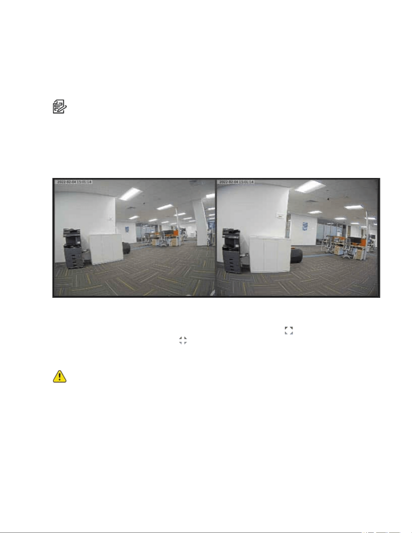
Using Multihead Camera Features
When configuring and using the Sarix Modular, you can configure many of the settings for each head on the
camera individually.
When you see the camera's video display, you will see two image panels displayed — one for each head
on the camera:
The left image panel is always for Head 1. The right image panel is for Head 2.
To control the video display:
l
Move your mouse into the image panel, and then click the maximize icon ( )to maximize the
image panel or click the restore icon ( )to restore the image panel.
Configuring General Imaging Settings
Caution:The Sarix Modular Camera has multiple camera heads in a single camera. Some settings
apply to the camera as a whole; other settings apply to individual heads. Certain multi-head camera
settings can be set globally for all of the heads. Other settings must be set for each individual head.
When configuring a camera, configure both the global and the individual head settings.
1. Click the Imaging tab, and then click the General button.
2. For each head, click Head [#] to select the head to focus.
3. View the following information:
l Current Exposure
l Current Gain
l Last Known Light Level

Sarix® Modular Camera Operations Manual
C6719M | 02/22
19
4. Select All Heads, and then adjust the video image as required.
a. Flicker Control: If your video image flickers because of fluorescent lights around the camera,
you can reduce the effects of the light by setting the Flicker Control to the same frequency as
your lights. Generally, Europe is 50Hz and North America is 60Hz.
Note
: Resetting this control will stop the video stream for a few seconds.
b. Enable Wide Dynamic Range: You can enable automatic color adjustments through Wide
Dynamic Range (WDR). This allows the camera to adjust the video image to accommodate
scenes where bright light and dark shadow are clearly visible. See the section titled
Understanding Backlight Compensation (BLC) and Wide Dynamic Range (WDR).
c. To apply the same day/night and exposure settings to all heads on the camera, in the
ImagingMode area, click to select Global from the drop-down menu.
d. To set day/night and exposure settings on a per-head basis, do one of the following:
l In the ImagingMode area, click to select Per-head from the drop-down menu.
l At the top of the left panel, for each head, click Head [#] to select the head to focus.
e. Perform the next step.
5. To set how the camera compensates for the environmental lighting conditions, define the following
Day/Night Settings:
a. Use the Day/Night Mode drop-down menu to set how the video image switches between day
and night mode.
l Automatic: When the light level is above the day/night threshold, the video image will be
in color. When the light level goes below the day/night threshold, the camera will switch to
monochrome mode.
l Color: The video image will always be in color.
l Monochrome: The video image will always be monochrome.
b. If you selected theAutomatic Day/Night Mode:
l Use the Day/Night Threshold (gain dB) slider to set the day/night threshold. Move the
slider to select the light level when the camera switches between day mode and night
mode.The slider is only available when the Day/Night Mode setting is set to Automatic.
The slider might display one of the following values:
– Day/Night Threshold (EV): The slider value is in Exposure Values (EV).
In day mode, the last known light level is displayed under the image panel and is also
shown as a blue bar on the Day/Night Threshold slider.
– Day/Night Threshold (gain dB): The slider value is in decibels (dB).
c. Enable Night Visibility Check: You can manually enable or disable the night visibility check
on a camera.The night visibility check, when enabled, performs a periodic test switching
between day/night mode to check if there is sufficient light level to switch from night mode to
day mode. When disabled, the camera will use a less optimal method to determine if the light
level is sufficient to switch to day mode.

Sarix® Modular Camera Operations Manual
C6719M | 02/22
20
Note
: Disabling the night visibility check could delay the camera from transitioning
between night and day modes and make the transition time less optimal. For example,
the camera stays in night mode 30 minutes longer than it needs to.
6. To adjust the exposure of the image, adjust the Exposure Settings:
l Exposure: Click to select the appropriate exposure rate from the drop-down menu. Allow the
camera to control the exposure by selecting Automatic. In some cases, Automatic is the only
option available.
Note
:
Exposure
is only available when
Wide Dynamic Range
is disabled.
Note
: Increasing the manual exposure time might affect the image rate.
l Maximum Exposure: If you selected Automatic as the Exposure Offset, you can limit the
automatic exposure setting by selecting a maximum exposure level. The Maximum Exposure
drop-down menu is only available when the Exposure setting is set to Automatic.
By setting a maximum exposure level for low-light situations, you can control the camera's
exposure time to let in the maximum amount of light without creating blurry images.
l Priority: If you selected Automatic as the Exposure Offset, you can set Image Rate or
Exposure as the priority.
– When set to Image Rate, the camera will maintain the set image rate as the priority and
will not adjust the exposure beyond what can be recorded for the set image rate.
– When set to Exposure, the camera will maintain the exposure setting as the priority, and
will override the set image rate to achieve the best image possible.
l Backlight Compensation: If your scene has areas of intense light that cause the overall
image to be too dark, click to select the checkbox for Backlight Compensation, and then enter a
value (either by typing a number, or selecting one using the up and down arrows) that results in
a well-exposed image. See the section titled Understanding Backlight Compensation (BLC)
and Wide Dynamic Range (WDR).
l Maximum Gain: To limit the automatic gain setting, click to select the the appropriate
Maximum Gain from the drop-down menu.
By setting the maximum gain level for low-light situations, you can maximize the detail of an
image without creating excessive noise in the images.
7. Click Apply to save the settings.
Understanding Backlight Compensation (BLC) and Wide Dynamic Range (WDR)
l BLC is a feature that optimizes exposure in the foreground and background of security video. BLC
uses a single exposure time for the whole image, and uses auto exposure to ignore very bright
regions (or very dark, if set negative). You must choose whether the camera optimizes the
foreground or the background.
l WDR enables advanced image processing, and helps draw out detail from both very bright and dark
areas in a scene. For example:Use WDRin lobbies or store fronts with natural light streaming in
through windows, where you also have dark areas in the same scene. WDR takes multiple
exposures of the scene in a single time slice. Two scans are taken of each video frame, one with a
short exposure optimized for brighter portions of the scene, the other longer to draw out detail in dark

Sarix® Modular Camera Operations Manual
C6719M | 02/22
21
areas. The image processing combines the two images to form one view, incorporating the best
detail and clarity across the entire scene.
If you enable both BLC and WDR, the camera will deliver the detail you will see in WDR-only mode, but will
ignore optimization on the very brightest (or darkest) portions of the image.
Adjusting White Balance Settings
Note: Features and options are disabled if they are not supported by the camera.
1. Click the Imaging tab, and then click the White Balance button.
2. For each head, click Head [#] to select the head.
a.a. View the following information:
l Current Exposure
l Current Gain
l Last Known Light Level
3. Select All Heads, and then adjust the video image as required.
You can either use a preset configuration, or you can create your own custom configuration. Use the
Preset drop-down menu to select the preferred configuration:
a. Pelco: This preset provides the recommended balance of brightness and color for video
surveillance.
b. Standard: This preset is configured for general day/night changes in an indoor or outdoor
scene.
c. Vivid: This preset provides increased color and brightness for a more saturated image.
d. Custom: Select this option to manually adjust the following image settings:
Note
: The
Brightness
and
Contrast
settings are disabled if you selected
Enable Wide
Dynamic Range
. See the section titled
Configuring General Imaging Settings
l Saturation: You can adjust the video’s color saturation by entering a percentage number.
0 creates a black and white image, while 100 creates intense color images.
l Sharpness: You can adjust the video’s sharpness by entering a percentage number.
0 applies the least amount of sharpening, while 100 applies the most sharpening to make
the edges of objects more visible.
l Brightness: You can adjust the video’s brightness by entering a percentage number.
0 creates a dark image, while 100 creates a light-filled image.
l Contrast: You can adjust the video’s contrast by entering a percentage number.
0 applies the least amount of contrast, while 100 applies the most contrast between
objects in the image.
Note
:You can select any preset, and make changes to the image settings. When you
apply the changes, the updated image settings are saved and the preset will change to
Custom
.
e. Move the Temporal Filter Strength slider slightly to the left or right to adjust the amount of noise
vs. blur in the scene. This reduces image noise by averaging the noise over several frames.

Sarix® Modular Camera Operations Manual
C6719M | 02/22
22
Note
: Start by making small adjustments only because applying excessive changes
might degrade the overall image quality.
If the image looks noisy, move the slider to the right to reduce the amount of noise in the scene
and decrease the bandwidth used.
If the image looks blurry, move the slider to the left to reduce the amount of blur in the scene
and increase the bandwidth used.
By default, the slider is set to the middle, which is 50.
4. For each head, click Head [#] to select the head to enhance. (This option is disabled for All Heads.)
a. Use the White Balance drop-down menu to select how the white balance settings are
controlled:
l Automatic: The camera will automatically control the white balance.
l Custom: Manually set the Red and Blue levels.
b. Click to select the checkbox for Dominant Color Compensation to enable an alternate auto
white balance algorithm which should be used when a large area in the field of view contains
one color. For example, a camera that is overlooking a grass field. For this example, the
Dominant Color Compensation white balance mode will improve the white balance to a more
neutral color.
5. Click Apply to save the settings.
Using Window Blanking
On the Window Blanking page, you can set window blanks in the camera’s field of view to block out areas
that you do not want to see or record. The camera supports up to 64 window blanks.
Window blanks can be applied to each head of a multi-head camera.
Setting a Window Blank
1. Click the Imaging tab, and then click the Window Blanking button.
2. Click to select the Head [#] on which to adjust the settings.
3. To add a window blank, click Add. A window blank box is added to the video image.
4. To define the window blanking box, perform any of the following:
a. Drag any side of the box to resize the window blank. Window blank boxes can only be
rectangular in shape.
b. Click inside the box then drag to move the window blank box.
5. Click Apply to save the settings.
Deleting a Window Blank
1. Use one of the following methods to delete a window blank:
l In the list of window blanks, click to select the name of the window blank to delete (Privacy
Zone [#]), and then click Remove.
l Click to select the window blank box to delete, click the X at the top-right corner of the gray box
to delete the window blank box, and then click OKin the confirmation dialog box.

Sarix® Modular Camera Operations Manual
C6719M | 02/22
23
2. Click Apply to save the settings.
3. Click OKin the confirmation dialog box.
Sarix® Modular Camera Operations Manual
C6719M | 02/22
24
Configuring A/V Streams
Configure compression and image rate, smart compression, RTSPstream URI, Still Image
URI,AudioConfigurations, and advanced smart compression on the A/V Streams page.
Compression and Image Rate
On the Compression and Image Rate page, you can change the camera’s compression and image quality
settings for sending video over the network.
Caution:The Sarix Modular Camera has multiple camera heads in a single camera. Some settings
apply to the camera as a whole; other settings apply to individual heads. Certain multi-head camera
settings can be set globally for all of the heads. Other settings must be set for each individual head.
When configuring a camera, configure both the global and the individual head settings.
To enable easy access and lower bandwidth usage, the web interface only displays video in JPEG format.
The settings on this page only affect the video transmitted to the network video management software.
Pelco High Definition H.264 IP cameras have dual stream capabilities. If the camera’s streaming format is
set to H.264, the camera's web interface can still display live video in JPEG format.
Note: Configure the camera's secondary stream using your VMS; it cannot be configured in the
camera's web client.
Note: The camera might automatically adjust compression quality in order to abide by the bandwidth
cap specified.
1. Click the A/V Streams tab, and then click the VideoConfigurations button.
2. In the Compression and ImageRate area, for each camera head:
a. Click Head [#] to select the head to configure.
b. In the Format drop-down menu, select the preferred streaming format for displaying the
camera video in the network video management software.
If you are using the Onboard Storage feature, select H.264 or H.265. For more information, see
Enabling Onboard Storage. Otherwise, select MJPEG.
c. In the Max Image Rate field, enter how many images per second you want the camera to
stream over the network.
Note
: Adjusting the image rate across the 30 fps boundary will stop the video stream for
a few seconds.
If the camera is operating in High Framerate mode, then the maximum image rate is increased.
For more information on the High Framerate mode, see Configuring General Settings.
d. In the Max Quality drop-down menu, select the desired image quality level.
Image quality setting of 1 will produce the highest quality video and require the most
bandwidth.
e. If you selected H.264 or H.265, in the Max Bitrate field, enter the maximum bandwidth the
camera can use.
f. In the Primary Resolution drop-down menu, select the preferred image resolution.

Sarix® Modular Camera Operations Manual
C6719M | 02/22
25
g. If you selected H.264 or H.265, in the Min Keyframe Interval field, enter the number of frames
between each keyframe.
3. Click Apply to save the settings.
Enabling and Configuring Smart Compression
Smart Compression technology operates by separating foreground objects and background areas, then
reduces bandwidth by increasing compression to the background areas. In this way, maximum quality is
retained for subjects of interest while reducing bandwidth for unchanging backgrounds.
When enabled, the camera will automatically switch to idle scene mode settings when there are no motion
events detected. A motion event is when the camera detects pixel motion in the scene. For more
information, see the section titled Configuring Motion Detection.
The camera uses pixel change motion to detect foreground objects and therefore uses the standard Motion
Detection sensitivity settings of the camera.
1. Click the A/V Streams tab, and then click the VideoConfigurations button.
2. In the Compression and ImageRate area, for each camera head, click Head [#] to select the head
to configure, and then perform the following steps.
3. In the Smart Compression Settings area, click to select the checkbox for Enable to enable Smart
Compression.
4. In the Min Image Rate field, enter how many images per second you want the camera to stream
when there is no motion in the scene.
5. If you selected H.264 or H.265, in the Idle Keyframe interval field, enter the number of frames
between each keyframe (between 1 and 254) when there is no motion in the scene.
6. In the Bandwidth Reduction drop-down menu, click to select one of the options:
l Low
l Medium (recommended)
l High
l Custom
7. Click Apply to save the settings.
8. If you chose Custom for the Bandwidth Reduction, see the section titled Configuring Smart
Compression Advanced Settings.
Saving or Restoring VideoConfigurations
After you have updated all settings on the VideoConfigurations page, do one of the following:
l Click Apply to save the settings.
l Click Restore Defaults to restore all settings (saved and unsaved) to the default settings.
Viewing the RTSP Stream URI
You can only generate the RTSP stream address in the camera web interface. The RTSP Stream URI
allows you to watch the camera’s live video stream from any application that supports viewing RTSP
streams, including many video players.
Note: You can only generate the RTSP stream address in the camera web interface.

Sarix® Modular Camera Operations Manual
C6719M | 02/22
26
1. Click the A/V Streams tab, and then click the VideoConfigurations button.
2. View the auto-generated URIs in the RTSP Stream URI area:
l Unicast — Use this URI to view the video stream from one video player at a time.
l Multicast — Use this URI to view the video from more than one video player simultaneously.
3. To view the RTSP stream:
a. Copy and paste the appropriate URI into your video player. DO NOT open the live video
stream yet.
b. Add your username and password to the beginning of the address in this format:
rtsp://<username>:<password>@<generated RTSP Stream URI>/
For example: rtsp://admin:admin@192.168.1.79/defaultPrimary?streamType=u
c. Open the live video stream.
Accessing the Still Image URI
On the A/V Streams tab, VideoConfigurations page, you can access the last still image frame that the
camera recorded.
1. Click the A/V Streams tab, and then click the VideoConfigurations button.
2. In the Still Image URI area, click the link.
l The last recorded frame of video from the camera’s secondary stream is displayed.
l You can save or print the image directly from the browser.
Audio
Use the settings on the Audio Configurations page to adjust the audio quality of the Video Intercom.
For encoding the audio stream, you can choose from the Opus sound encoder, which produces high-quality
sound, or the G.711 protocol sound encoder. Use the Opus encoder if you are using a video management
system that supports the Opus protocol. Otherwise use the widely supported G.711 protocol.
Echo cancellation and noise reduction are built into the Video Intercom. Echo cancellation removes the
speaker output signal from the microphone signal, which prevents the operator at the other end from
hearing an echo of their own voice. Noise reduction removes background noise from the microphone signal,
and you can set the sensitivity to background noise. You can also set the speaker volume and the
microphone output levels.
1. In the Audio Configuration section, in the Encoding field, specify the audio encoder to use:
l Opus:High quality audio codec is available if required.
l G.711: This default setting is supported on various platforms.
2. In the Device Speaker section, use the Volume slider to adjust the volume on the speaker (from 0 to
100).
3. In the Device Microphone section, use the Line In Gain slider to adjust the gain for any line-level
audio input that is connected to the audio input connector on the I/O terminal block.
4. Click Apply to save the settings.

Sarix® Modular Camera Operations Manual
C6719M | 02/22
27
Configuring Smart Compression Advanced Settings
If you enabled Smart Compression on the Video Configuration page (see the section titled Enabling and
Configuring Smart Compression), configure the Smart Compression Advanced Settings.
1. Click the A/V Streams tab, and then click the Smart Compression button.
2. Click Head 1.
Note
:This is a global setting, but it is set from the
Head 1
selection settings.
3. In the On Motion section, Background Quality field, enter the compression quality for the
background (between the default of 6 and the lowest setting of 20).
4. In the On Idle Scenes section, Post-motion delay field, enter the delay (in seconds) after motion
has ended before the camera drops into idle scene settings (between 5 and 60).
5. In the On Idle Scenes section, Image Rate field, enter the encoding frame rate (images per
second) when there is no motion in the scene.
6. In the On Idle Scenes section, Quality field, enter the compression quality when there is no motion
in the scene (between 6 and 20).
7. In the On Idle Scenes section, Max Bitrate field, enter the maximum number of kilobytes per
second when there is no motion in the scene.
8. In the On Idle Scenes section, Keyframe Interval field, enter the number of frames between each
keyframe when there is no motion in the scene (between 1 and 254 frames).
9. Click Apply to save the settings.

Sarix® Modular Camera Operations Manual
C6719M | 02/22
28
Configuring Events
Use the Events tab to configure Motion, Sabotage, and DIOsettings.
Caution:The Sarix Modular Camera has multiple camera heads in a single camera. Some settings
apply to the camera as a whole; other settings apply to individual heads. Certain multi-head camera
settings can be set globally for all of the heads. Other settings must be set for each individual head.
When configuring a camera, configure both the global and the individual head settings.
Configuring Motion Detection
On the Motion Detection page, you can define the green motion detection areas in the camera’s field of
view. Motion detection is ignored in areas not highlighted in green.
To help you define motion sensitivity and threshold, motion is highlighted in red in the image panel.
Note: This motion detection setting configures pixel change detection in the camera's field of view. If
you are configuring a Pelco video analytics camera, you will need to configure the detailed analytics
motion detection and other video analytics features through the Client software.
1. Click the Events tab, and then click the Motion button.
2. For each camera head, click Head [#] to select the head to configure, and then perform the following
steps.
3. Define the motion detection area.
The entire field of view is highlighted for motion detection by default. To define the motion detection
area, use any of the following tools:
l Click Clear All to remove all motion detection areas on the video image.
l Click Set All to set the motion detection area to span the entire video image.
l To set a specific motion detection area, click Select Area then click and drag anywhere on the
video image.
l To clear a specific motion detection area, click Clear Area then click and drag over any motion
detection area.
l Use the Zoom In and Zoom Out buttons to locate specific areas in the video image.
4. In the Sensitivity field, enter a percentage number to define how much each pixel must change
before it is considered in motion.
The higher the sensitivity, the smaller the amount of pixel change is required before motion is
detected.
5. In the Threshold field, enter a percentage number to define how many pixels must change before
the image is considered to have motion.
The higher the threshold, the higher the number of pixels must change before the image is
considered to have motion.
6. If the camera is connected to a third-party video management system (VMS), click AllHeads, and
then click to select the checkbox for Enable Onvif MotionAlarm Event.
When it is enabled, the H.264 camera can send motion alarm information to the VMS according to
the appropriate ONVIF protocol.
7. Click Apply to save the settings.

Sarix® Modular Camera Operations Manual
C6719M | 02/22
29
Configuring Sabotage Detection
On the Sabotage Detection page, you can set how sensitive the camera is to tampering.
To set the options for tampering:
1. Click the Events tab, and then click the Sabotage button.
2. For each camera head, click Head [#] to select the head to configure, and then perform the following
steps.
3. If necessary, click to select the checkbox for Enable Tamper Detection. This is the default setting.
4. In the Sensitivity field, enter a number between 1 and 10 to define how sensitive the camera is to a
sudden change in the scene. The higher the setting, the more sensitive the camera is to detect
scene changes.
Note
: A sudden change in the scene is usually caused by someone unexpectedly moving the
camera. Lower the setting if small changes in the scene, like moving shadows, trigger too
many tampering events. If the camera is installed indoors and the scene is unlikely to change,
you can increase this setting to capture more unusual events.
5. In the Trigger Delay (seconds) field, enter the number of seconds (up to 30 seconds) that the
sabotage condition must persist in the scene before the sabotage event is sent.
Configuring Digital Inputs and Outputs
On the Digital Inputs and Outputs page, you can set up the external input and output devices that are
connected to the camera. This option does not appear for cameras that do not support digital inputs and
outputs.
1. Click the Events tab, and then click the DIO button.
2. To configure a digital input:
a. Enter a name for the digital input in the Name field.
b. Select the appropriate state from the Circuit State drop-down menu. The options are:
l Normally Open
l Normally Closed
c. Click Apply to save the settings.
After the digital input is connected to the camera, you will see the connection status in the
Circuit Current State field. The status is typically Open or Closed.
3. To configure a digital output:
a. Enter a name for Digital Output 1 or Digital Output 2 (if present) in the Name field.
b. Select the appropriate state from the Circuit State drop-down menu.
c. In the Duration field, enter how long the digital output is active when triggered. You can enter
any number between 100 and 86,400,000 milliseconds.
d. Click Trigger to manually trigger the digital output from the web interface.
e. Click Apply to save the settings.

Sarix® Modular Camera Operations Manual
Pelco, Inc.
625 W. Alluvial Ave., Fresno, California 93711 United States
(800) 289-9100 Tel
(800) 289-9150 Fax
+1 (559) 292-1981 International Tel
+1 (559) 348-1120 International Fax
www.pelco.com
Pelco, the Pelco logo, and other trademarks associated with Pelco products referred to in this publication are trademarks of Pelco, Inc.
or its affiliates. ONVIF and the ONVIF logo are trademarks of ONVIF Inc. All other product names and services are the property of their
respective companies. Product specifications and availability are subject to change without notice.
© Copyright 2022, Pelco, Inc. All rights reserved.