
© 2024 GeoVision, Inc. All rights reserved.
Under the copyright laws, this manual may not be copied, in whole or in part,
without the written consent of GeoVision.
Every effort has been made to ensure that the information in this manual is
accurate. GeoVision, Inc. makes no expressed or implied warranty of any kind
and assumes no responsibility for errors or omissions. No liability is assumed
for incidental or consequential damages arising from the use of the information
or products contained herein. Features and specifications are subject to
change without notice.
GeoVision, Inc.
9F, No. 246, Sec. 1, Neihu Rd.,
Neihu District, Taipei, Taiwan
Tel: +886-2-8797-8377
Fax: +886-2-8797-8335
http://www.geovision.com.tw
Trademarks used in this manual: GeoVision, the GeoVision logo and GV
series products are trademarks of GeoVision, Inc. Windows is the registered
trademark of Microsoft Corporation.
August 2024
Scan the following QR codes for product warranty and technical support
policy:
[Warranty] [Technical Support Policy]

Statement ................................................................................................................................. 1
1 Overview .......................................................................................................................... 2
1.1 Scope of Application ............................................................................................. 2
1.2 Product Description ............................................................................................... 3
1.3 Operating Environment......................................................................................... 3
1.4 Camera Overview .................................................................................................. 4
1.4.1 GV-RBL5800 ..................................................................................................... 4
1.4.2 GV-RBL5811 ..................................................................................................... 5
1.4.3 GV-REB5800 ..................................................................................................... 6
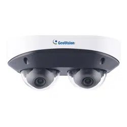
1.4.4 GV-RFER12700 ................................................................................................ 7
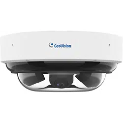
1.4.5 GV-RMS32810 .................................................................................................. 8
2 Device Connection.......................................................................................................... 9
2.1 Connecting to a PC ............................................................................................... 9
2.2 Connecting Through a Router/Switch ................................................................ 9
3 Setting the IP Address of an IPC Using GV-IP Device Utility ................................ 10
4 Login from Web Client.................................................................................................. 13
4.1 Accessing Camera from Web Client ................................................................ 13
4.2 When You Log in for the First Time .................................................................. 14
4.3 Normal Login ........................................................................................................ 16
4.4 Password Retrieval ............................................................................................. 16
4.4.1 Security Question Configuration ................................................................... 17
4.4.2 Certificate of Authorization ............................................................................ 17
4.4.3 Super Code ...................................................................................................... 18
4.5 Password Aging ................................................................................................... 18
5 Installing Plug-in ............................................................................................................ 19
6 Live View ........................................................................................................................ 20
6.1 Live View Menu ................................................................................................... 20
6.1.1 Fisheye Correction .......................................................................................... 22
6.2 Recording Status ................................................................................................. 42
7 Playback ......................................................................................................................... 43

7.1 Normal Playback ................................................................................................. 43
7.2 Image Search ....................................................................................................... 46
7.3 Playback by Tag .................................................................................................. 47
7.4 Smart ..................................................................................................................... 48
7.5 AI ............................................................................................................................ 50
7.5.1 Face Search and Playback............................................................................ 50
7.5.2 Pedestrian and Vehicle Search and Playback ........................................... 52
7.5.3 PID&LCD .......................................................................................................... 53
7.5.4 Intrusion ............................................................................................................ 54
7.5.5 Region Entrance / Exiting .............................................................................. 55
7.5.6 Repeat Visitor .................................................................................................. 56
7.5.7 Face Attendance ............................................................................................. 58
8 Remote Setting ............................................................................................................. 62
8.1 Live View .............................................................................................................. 62
8.2 Image Control ...................................................................................................... 63
8.3 Video Cover .......................................................................................................... 66
8.4 ROI ........................................................................................................................ 67
8.5 Recording Parameters ........................................................................................ 68
8.5.1 Encoding Parameters ..................................................................................... 68
8.5.2 Recording Parameters ................................................................................... 69
8.5.3 Capture ............................................................................................................. 71
8.6 Event Setup .......................................................................................................... 73
8.6.1 Parameter Setup ............................................................................................. 73
8.6.2 Alarm Setting ................................................................................................... 77
8.6.3 Event Push Platform ....................................................................................... 83
8.7 AI ............................................................................................................................ 85
8.7.1 Setup ................................................................................................................. 85
8.7.2 Recognition .................................................................................................... 104
8.7.3 Alarm Setup ................................................................................................... 106
8.7.4 Statistics ......................................................................................................... 111
8.8 Network Settings ............................................................................................... 115
8.8.1 Basic Settings ................................................................................................ 115

8.8.2 Email Setting .................................................................................................. 119
8.8.3 FTP Server Settings ..................................................................................... 120
8.8.4 RTSP Settings ............................................................................................... 121
8.8.5 Dynamic Domain Name Settings (DDNS)................................................. 122
8.8.6 HTTPS Settings ............................................................................................. 123
8.8.7 IP Filter ........................................................................................................... 123
8.8.8 Platform Access ............................................................................................ 124
8.9 Device Management ......................................................................................... 127
8.9.1 Disk Management ......................................................................................... 127
8.9.2 Audio Management ....................................................................................... 129
8.10 System Settings ................................................................................................. 129
8.10.1 General ....................................................................................................... 130
8.10.2 Multi-user Management ........................................................................... 133
8.10.3 System Maintenance ................................................................................ 135
8.10.4 System Information .................................................................................. 139
9 Local Settings .............................................................................................................. 140

1
Statement
Thank you for using our IP camera series. A powerful SoC (System on a Chip) is used as the
media processor to automate audio and video acquisition, compression, and transmission. The
standard H.264/H.265 coding algorithm guarantees a clearer and smoother video transmission.
The embedded web server allows users to easily and instantaneously monitor and remotely
control front-end cameras from Web browsers.
This series of IP cameras are suitable for large and medium-sized enterprises, government
projects, shopping malls, chain supermarkets, intelligent buildings, hotels, hospitals, schools and
other customer groups, and all kinds of places where remote network video transmission and
monitoring will be applied. This product is easy to install and user friendly.
Introduction:
⚫ In this manual, IP cameras refer to network cameras.
⚫ Click indicates click on the left mouse button.
⚫ Double click indicates double click on the left mouse button.
⚫ The default IP address of an IP camera is 192.168.0.10.
⚫ The default administrator username for IP camera is admin (in lowercase), and there is no
default password.
⚫ The web port number is 80 by default. The ONVIF port number is the same as the web port
number. The media port number is 9000 by default.
Notes:
Some information contained in this manual may differ from the actual product. For any problems
that cannot be solved using this manual, please feel free to contact our technical support or
authorized agent. This manual is subject to change without prior notice.
2
1 Overview
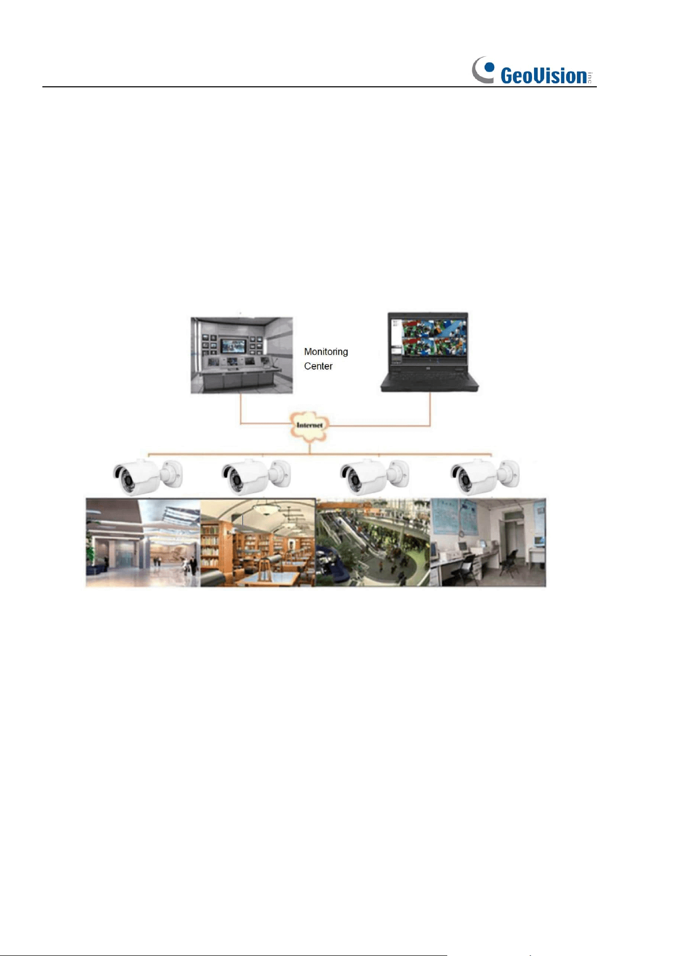
1.1 Scope of Application
IP cameras with powerful image processing capabilities can be applied in various public
places such as shopping malls, supermarkets, schools, factories and workshops, as well as
environments requiring high-definition video images such as banks and traffic control systems,
as shown below:

3
1.2 Product Description
An IP camera is a digital network monitoring camera that can operate independently with a
built-in web server, and can be used for real-time monitoring from all over the world by using a
web browser or client software.
The IP camera, based on the state-of-the-art digital solution, is an integrated media
processing platform for audio/video acquisition, compression and network transmission on a
single board. It complies with H.264/H.265 High Profile coding standard. By typing the IP
camera's IP address or domain name into a web browser, any remote user can perform
real-time monitoring. The IP camera solution is suitable for residential or commercial
environments, as well as a variety of places requiring remote network video surveillance and
transmission. The product is easy to install and user friendly.
The IP camera allows you to set multiple users with different permissions for easy
management.
The IP camera has the motion detection function, and will actively send E-mail, captured
images or alarm video when an event occurs and store the alarm video in the SD Card for
easy retrieval.
1.3 Operating Environment
System: Windows XP/Windows 7/ Windows 8/ Windows 10/ Windows 11/MacOS 10 or later.
CPU: Intel I3 or later
Memory: 2 GB or higher
Video memory: 1 GB or higher
Display: 1024×768 or higher
Browsers: IE10 and later, Chrome 57 and later, Firefox 52 and later, Edge 41 and later, and
Safari 12 and later
4
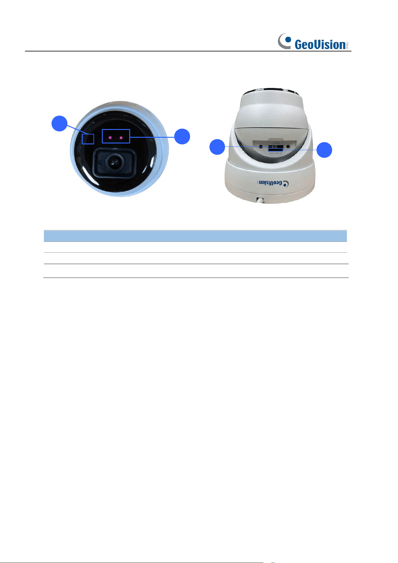
1.4 Camera Overview
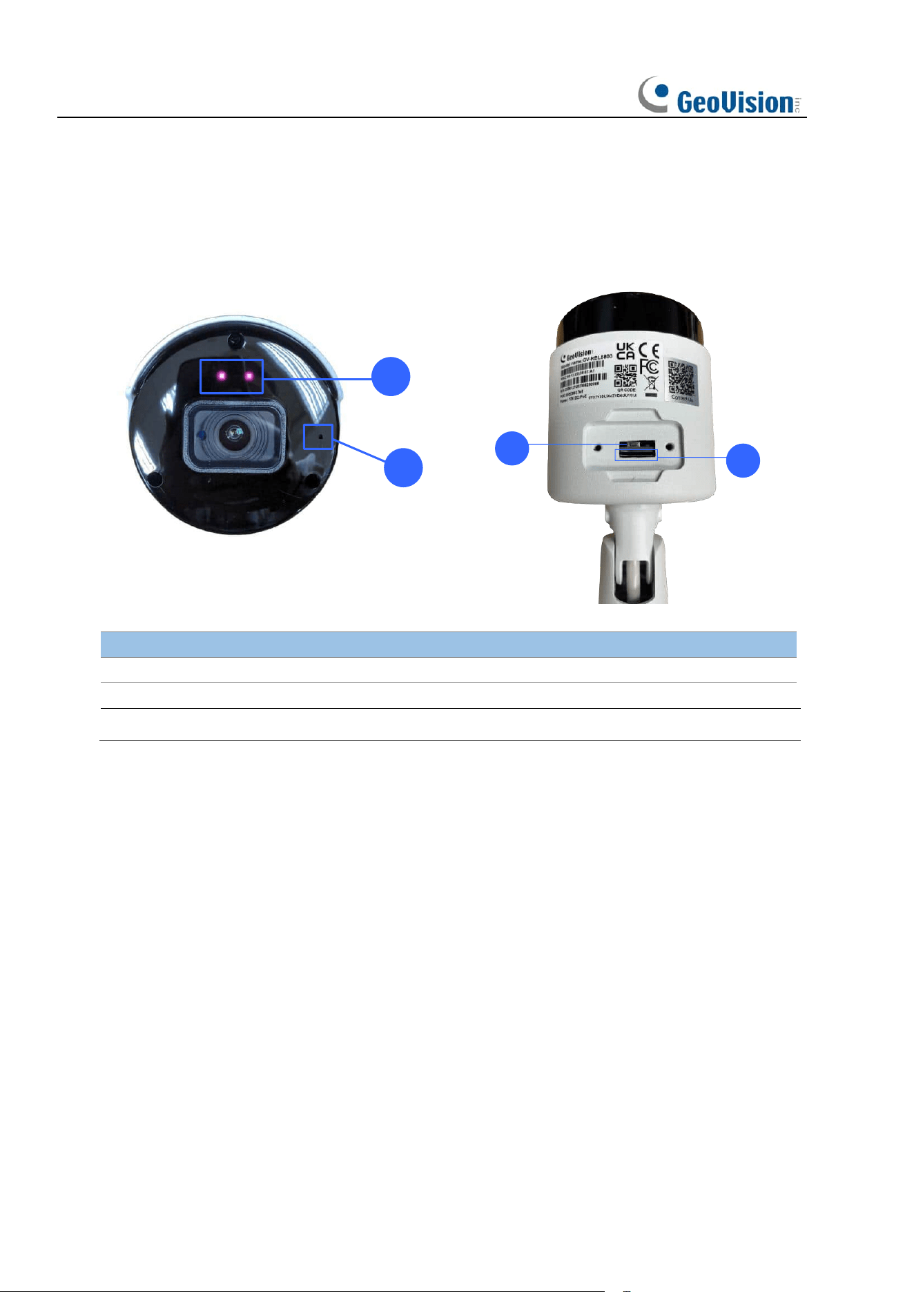
1.4.1 GV-RBL5800
1
2
3
4
No.
Description
No.
Description
1
IR LED x 2
3
Default button
2
Built-in microphone
4
SD card slot
Note: Press the default button for 15 seconds to reboot the camera.
5
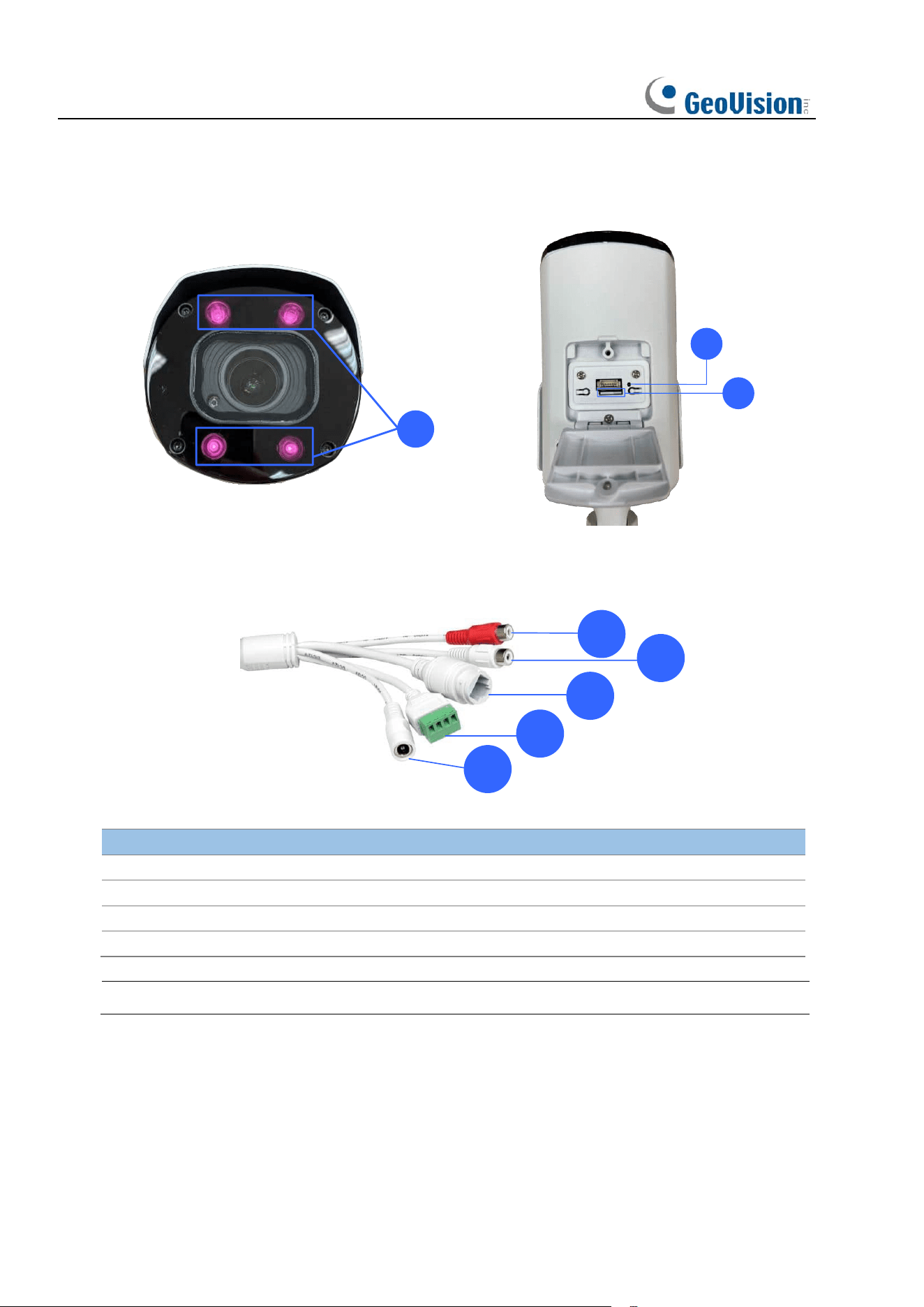
1.4.2 GV-RBL5811
1
2
3
4
5
6
7
8
No.
Description
No.
Description
1
IR LED x 4
5
Audio output
2
Default button
6
LAN / PoE port
3
SD card slot
7
Alarm in / GND / COM / Alarm out
4
Audio Input
8
Power connector (DC 12 V)
Note: Press the default button for 15 seconds to reboot the camera.
6
1.4.3 GV-REB5800
1
2
3
4
No.
Description
No.
Description
1
IR LED x 2
3
Default button
2
Built-in microphone
4
SD card slot
Note: Press the default button for 15 seconds to reboot the camera.
7
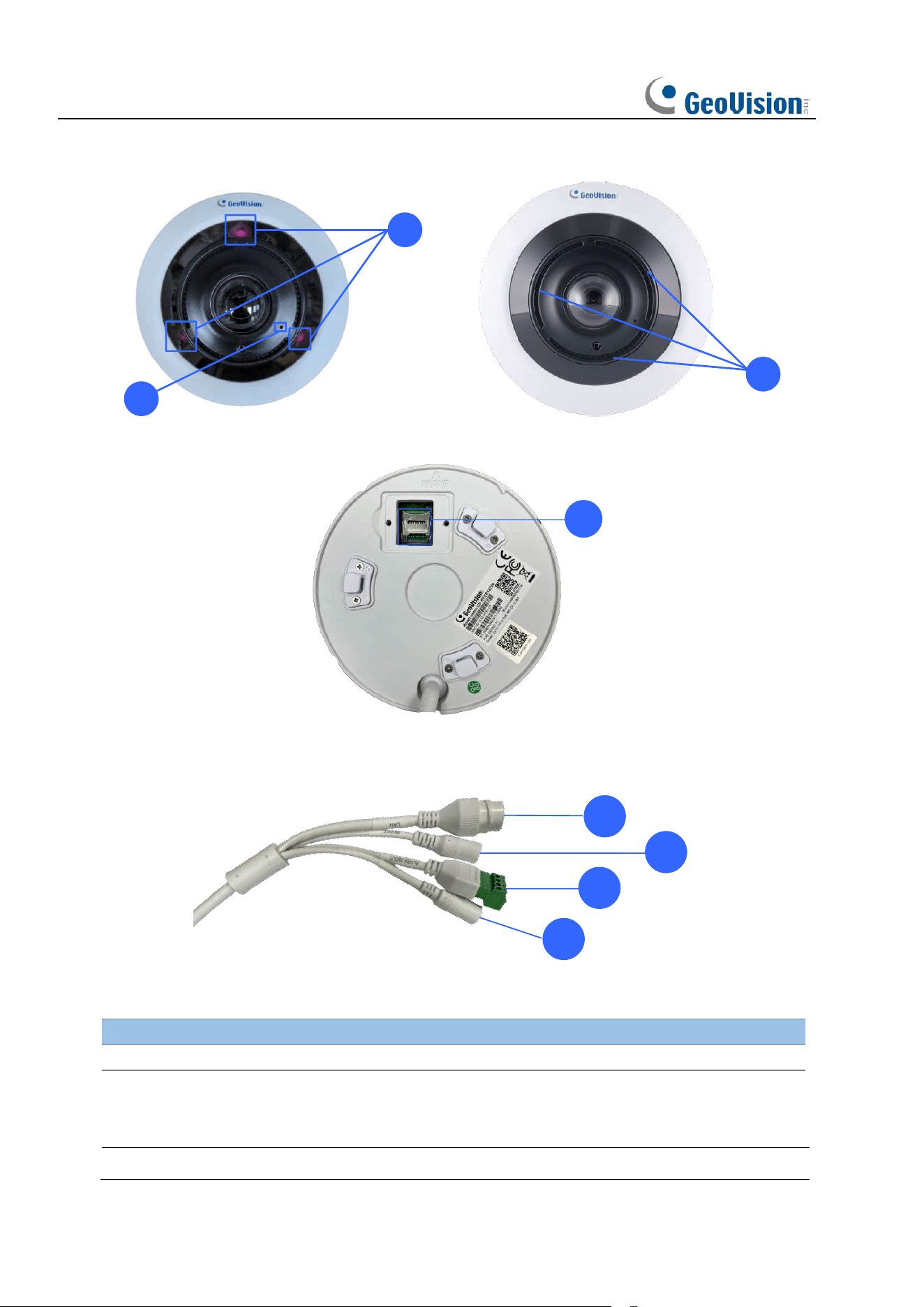
1.4.4 GV-RFER12700
1
2
3
4
5
6
7
8
No.
Description
No.
Description
1
IR LED x 3
5
LAN / PoE port
2
Built-in microphone
6
Default button
3
Built-in speaker
7
Alarm in / GND / COM / Alarm out
4
SD card slot
8
Power connector (DC 12 V)
Note: Press the default button for 15 seconds to reboot the camera.
8
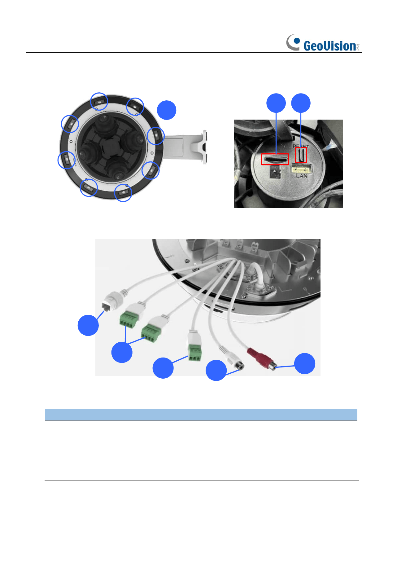
1.4.5 GV-RMS32810
1
2 3
4
5
6
7
8
No.
Description
No.
Description
1
IR LED / Warm LED x 8
5
Alarm in / Alarm out
2
SD card slot
6
Power connector (DC 12 V, AC 24 V)
3
Default button
7
Audio out
4
LAN / PoE port
8
Audio in
Note: Press the default button for 15 seconds to reboot the camera.
9
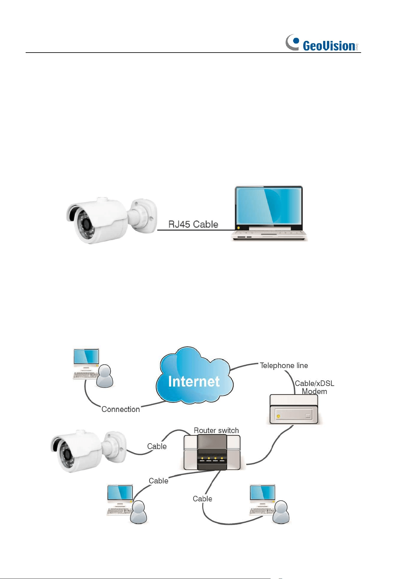
2 Device Connection
An IP camera can be connected in two ways:
2.1 Connecting to a PC
Directly connect an IP camera to a PC through a network cable, connect the power input to
the DC 12V adapter, and set the IP addresses of the PC and the IP camera on the same
network segment. If the network is running properly, the IP camera will communicate with the
PC within one minute after turned on.
2.2 Connecting Through a Router/Switch
This connection method is used when an IP camera is connected to the Internet where the IP
camera and PC are connected to the LAN ports of a router/switch and the gateway of the
camera is set to the IP address of the router.
10
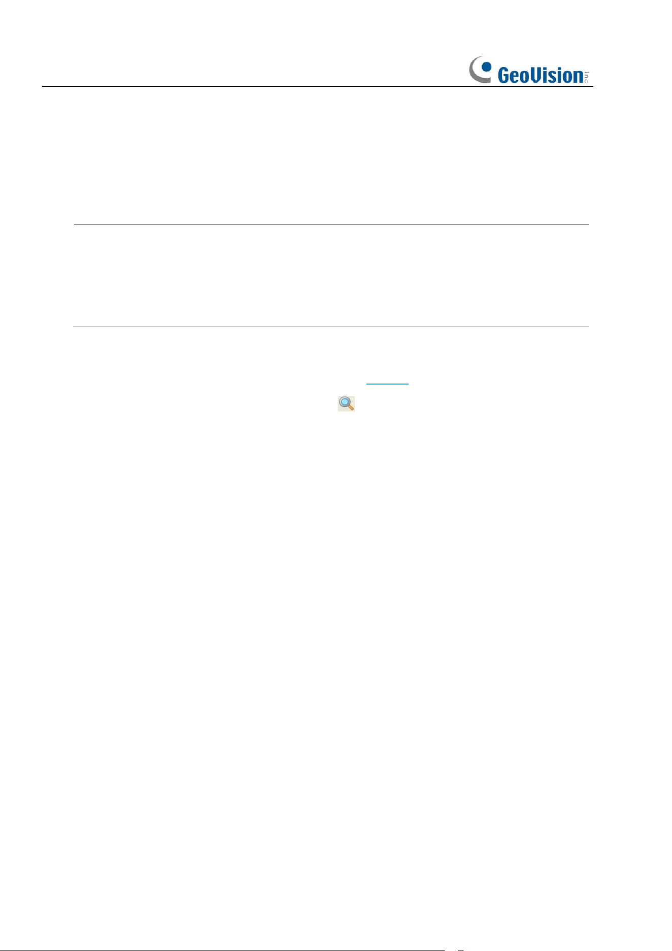
3 Setting the IP Address of an IPC Using GV-IP Device Utility
By default, when the camera is connected to LAN with DHCP server, it is automatically
assigned with a dynamic IP address. Follow the steps below to find the camera and set the IP
address for the camera using GV-IP Device Utility.
Note:
1. This function is only applicable on GV-IP Device Utility V9.0.1 or later for
GV-RBL5800 / RBL5811 / REB5800 / RFER12700.
2. This function is only applicable on GV-IP Device Utility V9.0.2 or later for
GV-RMS32810.
1. Make sure the PC and the camera are connected to the LAN, and GV-IP Device Utility
(V9.0.1 or later) is installed on the PC from our website.
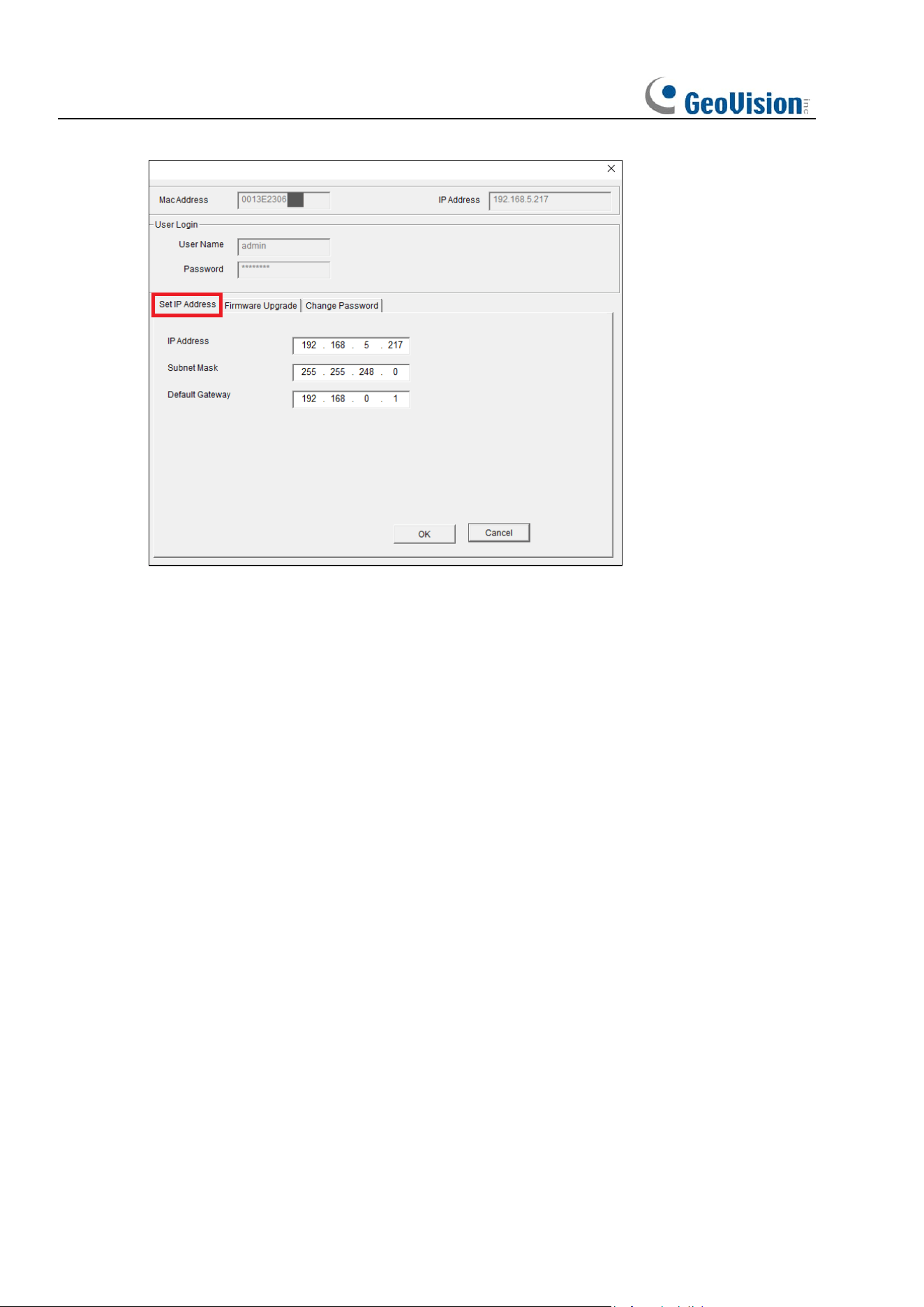
2. On GV-IP Device Utility window, click the button to search for the IP devices in the
same LAN. Click the Name or Mac Address column to sort.
11
3. Find the camera with its Mac Address, click on its IP address.
4. For first-time users, you are requested to create a password.
5. Type a new password and click OK.
6. Repeat Step 2 ~3 to find the camera on the search results again.
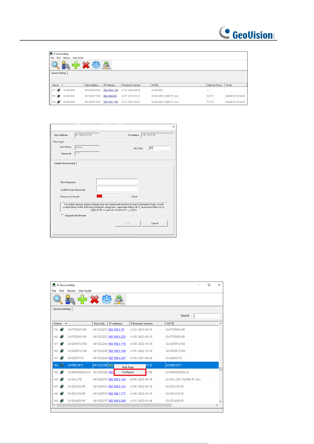
7. Click on its IP address and select Configure.
12
8. Log in the camera, and select the Set IP Address tab on the following page.
9. Type the desired IP address and click OK.
13
4 Login from Web Client
4.1 Accessing Camera from Web Client
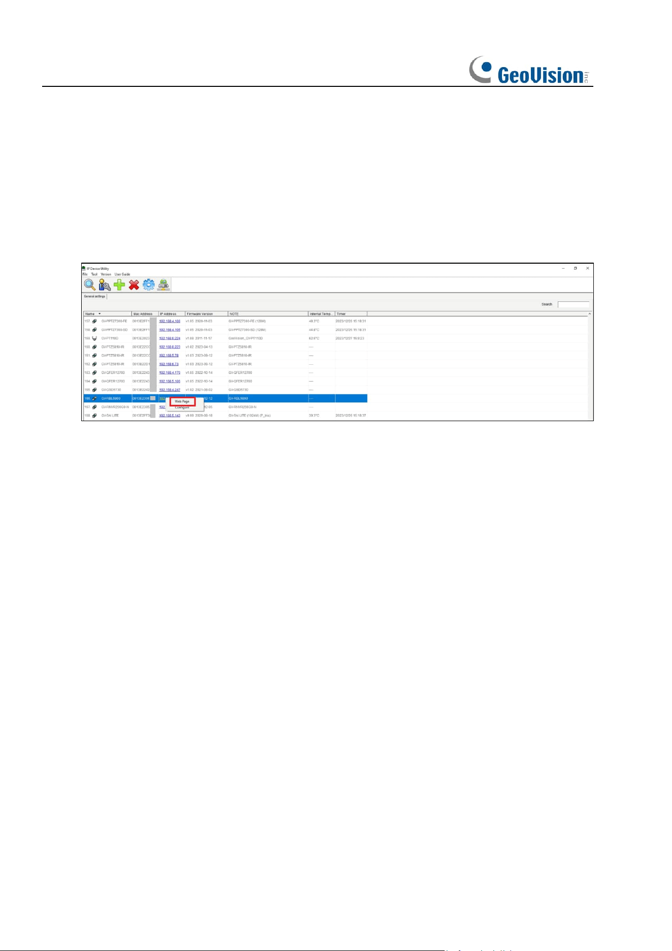
Use GV-IP Device Utility to search for the IPCs in the current network. As shown in the
following figure, click the camera’s IP address and select Web Page to log into its Web
interface.
As an alternative, you can open your Web browser and type the following information into the
address bar: HTTP://ip:web port. For example, if the IP address of the device to be accessed
is 172.20.58.41, the web port No. is 80, and the combined URL is http://172.20.58.41:80.
Note: In practical applications, the default HTTP access mode is port 80.
14
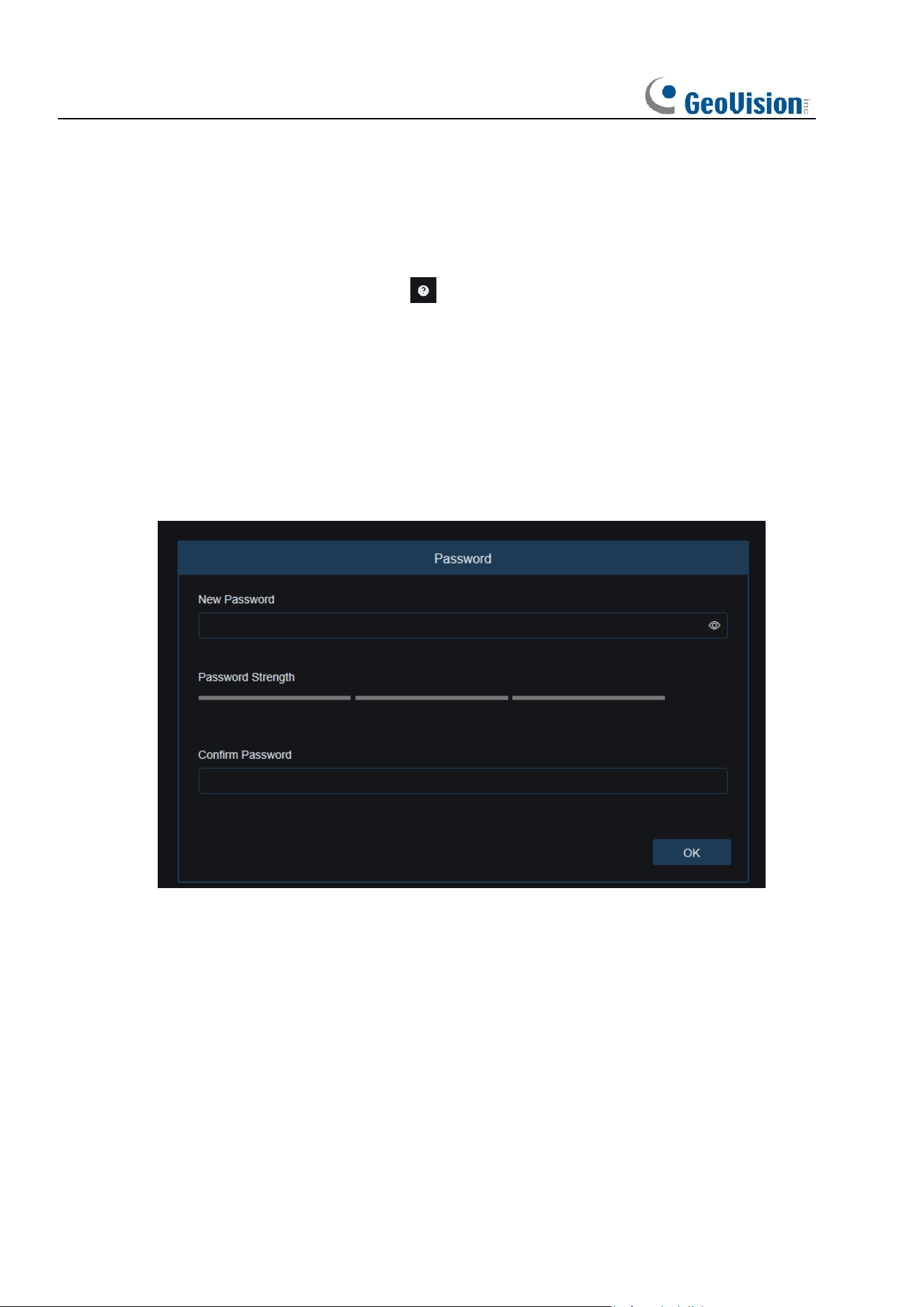
4.2 When You Log in for the First Time
Firstly, access the camera from a web client. The program will pop up the screen asking you
to set a more complex password. Click to check password setting requirements:
A password must be 8 to 15 characters long consisting of letters, digits or special characters.
1. A string of 8 to 9 characters containing at least three uppercase letters, lowercase letters,
digits, or special characters.
2. A string of 10 to 15 characters containing at least two uppercase letters, lowercase letters,
digits, or special characters.
3. Do not contain more than four consecutive or repeated characters.
4. Do not contain more than four consecutive key patterns.
Set a new password and click OK to save your change. The web client will display the screen
as shown below. Users can open the corresponding password retrieval method by checking
the box, or cancel the setting directly without enabling the password retrieval function.
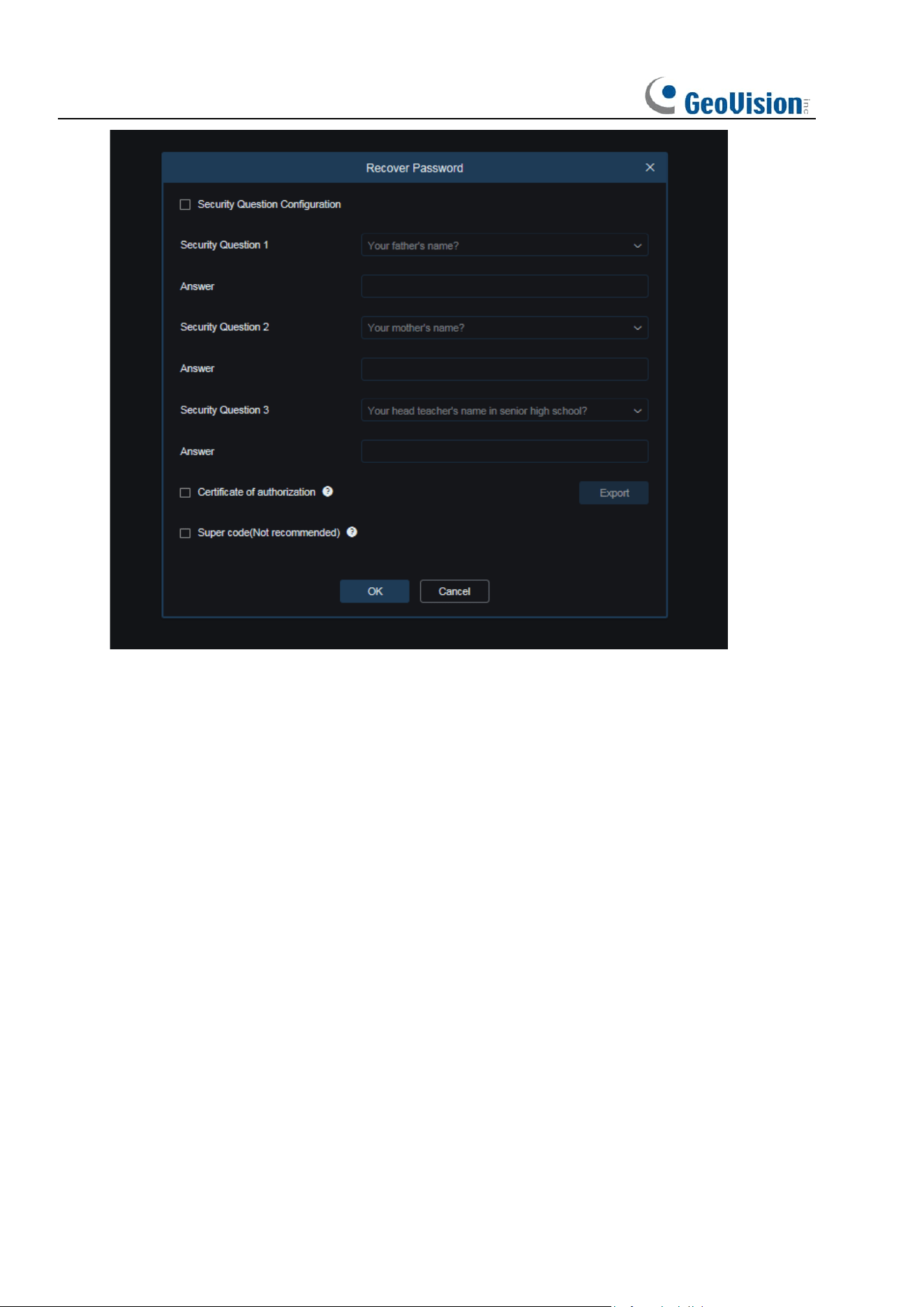
15
1. Security Question Configuration: To change the user password by question verification,
check the Security Question Configuration, select three questions among 15 questions,
and set the answers at a maximum length of 64 characters to retrieve your password.
2. Certificate of authorization: To change the user password by using a certificate, check
the Certificate of authorization, and click Export to download the certificate.txt file.
3. Super code (Not recommended): This method is to calculate a super code allowing to
changing the user password by using the MAC address of the camera and camera time.
You are not advised to enable this function as the MAC address of the camera is
broadcast over the network, and the system time of the camera can be directly obtained
when you log in from the web client and use Super code to change the user password.
Note: Keep your verification information properly when the password retrieval function is
enabled.
16
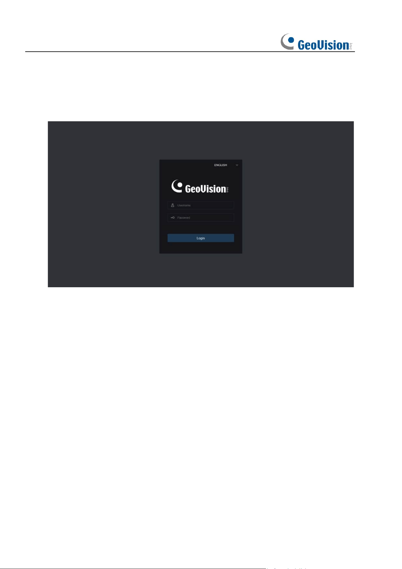
4.3 Normal Login
After accessing the camera from web client, you will be directed to the login screen as shown
below. Then, input your username and password, and click Login to access the operation
screen. At the same time, you can select your desired language upon login.
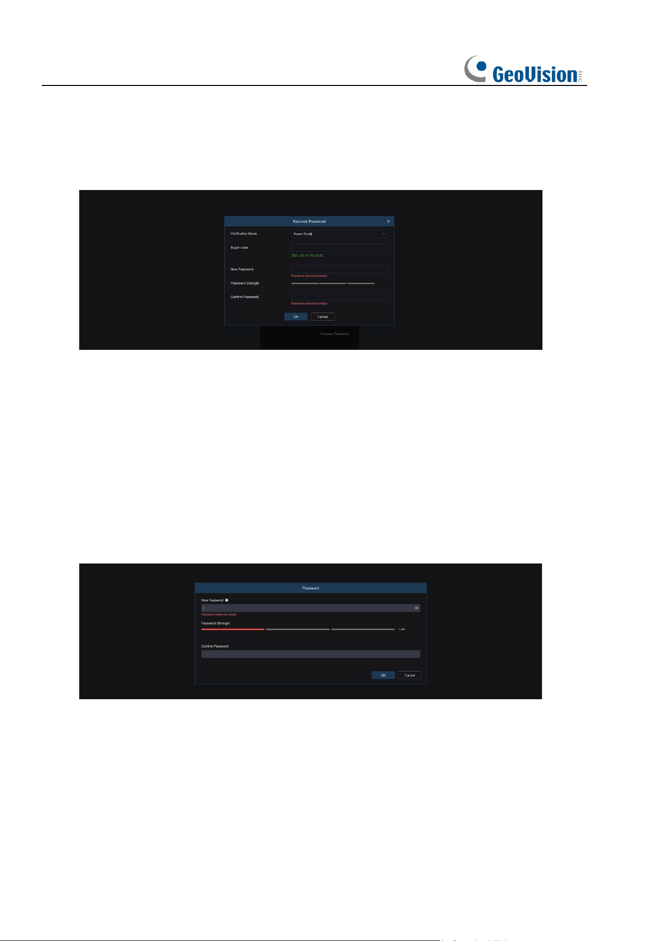
4.4 Password Retrieval
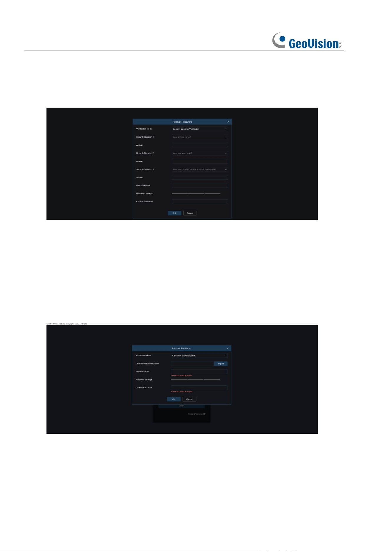
When the password retrieval function is enabled, if you forget the login information, you can
click Recover Password to enter the Recover Password screen. You can check security
question configuration, certificate of authorization, or super code upon first login to retrieve
your password.
17
4.4.1 Security Question Configuration
You can change the user password by setting security questions on the Recover Password
screen, as shown below. Fill in the answers to security questions. You can directly change the
user password.
4.4.2 Certificate of Authorization
When you set security questions upon first login, you will be asked to download the
certificate.txt when you choose to retrieve the user password by using Certificate of
authorization. On the Recover Password screen, click the Recover Password and import the
certificate.txt file to reset the password, as shown below. Click Import and select the
certificate.txt file. Then, enter a new password to change the user password.
18
4.4.3 Super Code
A super code is an insecure way to retrieve the password. The super code is calculated based
on the MAC address of the camera and the time of the super verification code according to
certain rules. Then the user password can be changed by entering the verification code.
4.5 Password Aging
Security risks may arise if you use the same password for a long period of time. To this end,
the program records the time when the password was changed last time. The system will ask
you whether to change the password again if the current login time is 90 days later than the
last password change time.
When you decide to change the password, the screen as shown below displays. As instructed
on the screen, use your old password for verification and set a new password.
19
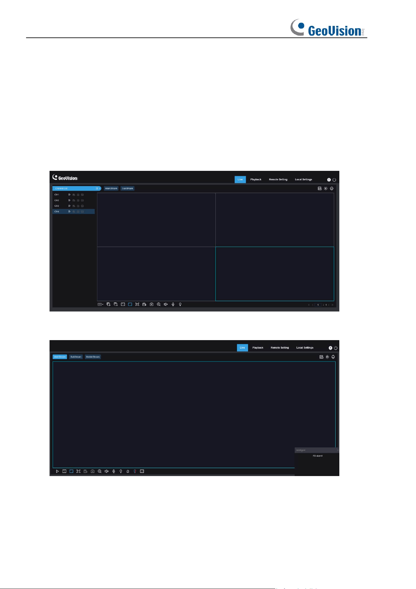
5 Installing Plug-in
An image can be normally previewed only when the plug-in is installed when you log in from
your IE browser. Download and install the plug-in as instructed on the screen as shown below.
Note: You can skip the plugin installation when you access the web client from Safari 12 and
later, Chrome 57 and later, Firefox 52 and later, and Edge 41.
20
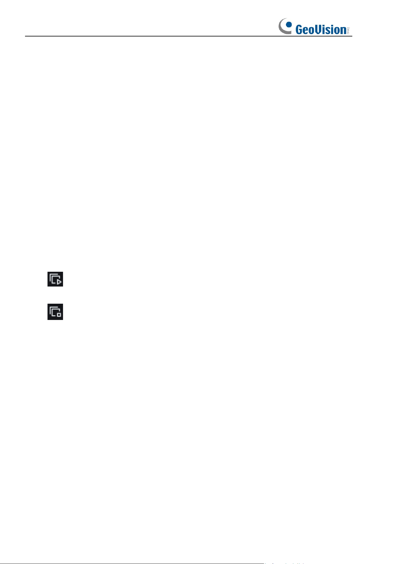
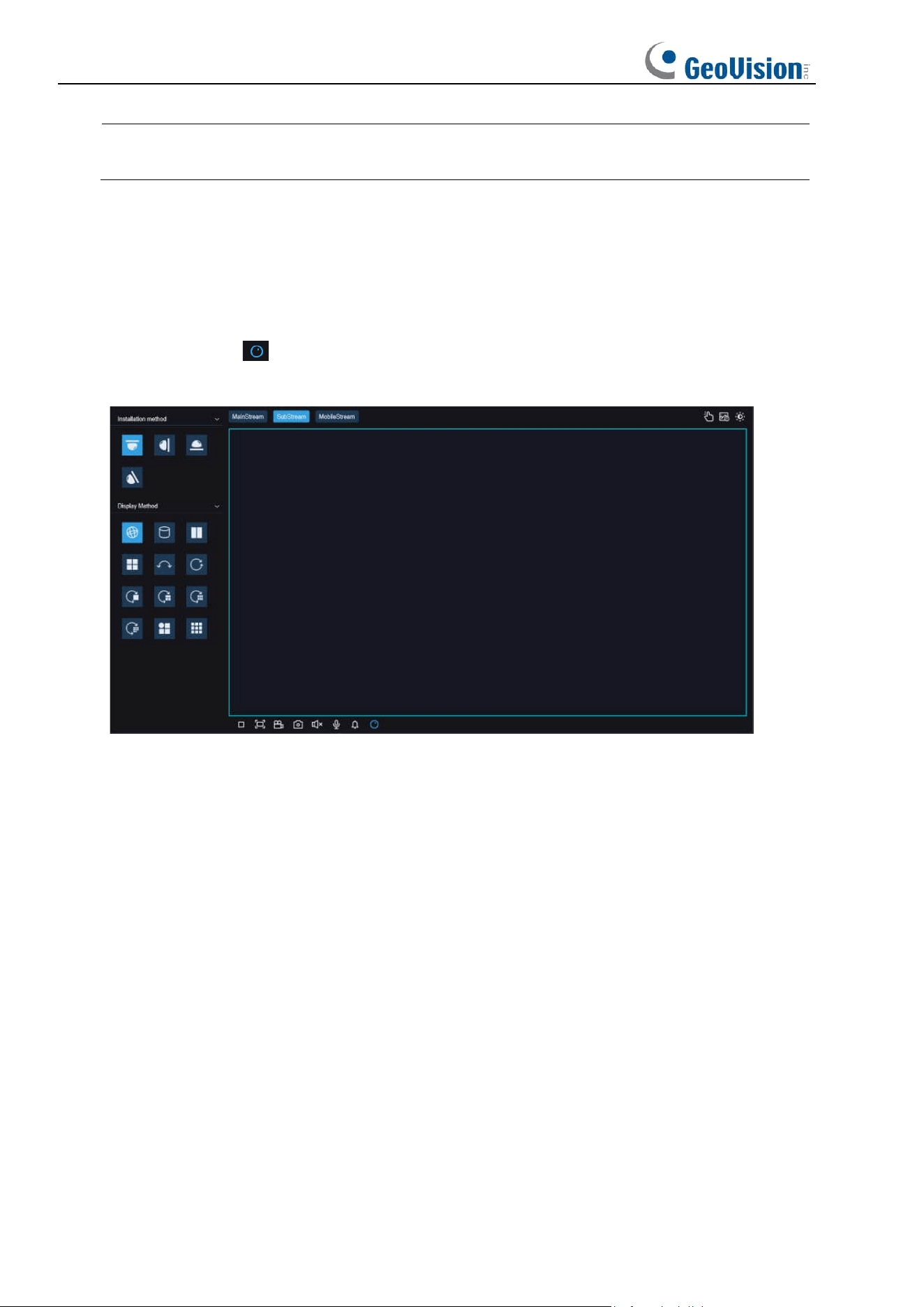
6 Live View
6.1 Live View Menu
The web client enters the login live view upon login, as shown in the figure below.
Note: Features may differ depending on product models.
For GV-RMS32810
Other models
Stream switching menu: You can switch the picture quality of the current live view at the
upper left corner:
Main stream: HD picture, but higher requirements on bandwidth and PC performance.
21
Sub stream: Moderate requirements on bandwidth and PC performance, but lower picture
quality when compared with main stream.
Mobile stream: Lowest requirements on bandwidth and PC performance, and lowest picture
quality.
Main switching bar: Switches web function screens. The web client provides four menus:
Live, Playback, Remote Setting, Local Settings.
Info: Displays the information about the active user, web version and plugin version.
Exit: Log out.
AI alarm: Used to open the alarm push bar on the right and push images during face alarming
and human & vehicle detection.
Color: Used to adjust the current image settings, such as image saturation and sharpness.
PTZ Setting: Used for PTZ settings and re-focusing.
Recording & alarm status: Displays the alarm and recording status of the camera. For
details, see Section 6.2.
Stop/Play: Used to play and stop the preview of the current stream.
Bitrate: Used to switch between main stream and sub stream in the current live view.
Division screen: Users can click this icon to select different layouts to display them in live
view.
Play: Used to play streams of all channels in live view (only applicable to
GV-RMS32810).
Stop: Used to stop streams of all channels in live view (only applicable to
GV-RMS32810).
Original Proportions: Displays the current live view in its original proportion.
Stretch: Displays the current live view in a way that stretches the display area.
Full Screen: Displays the live view in full screen. You can double-click the screen to enable or
disable the function, and press Esc to exit the full screen mode.
Record: Used to manually record the stream in preview.
Capture: Used to manually capture the image of the current stream.
Digital Zoom: Used to zoom in a certain area of the display.
Audio: Used to turn on/off or adjust the audio in preview.
Voice Intercom: Used to communicate with the camera.
Warning Light: Used to manually turn on/off the white light.
Pixel Counter: Used to select an area to check its pixel size in the stream.
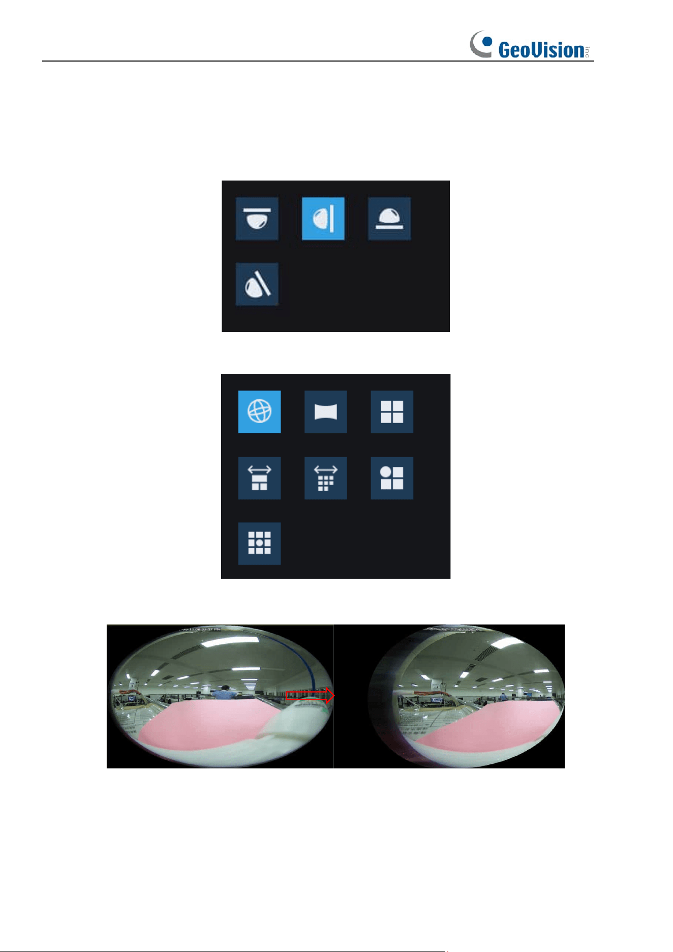
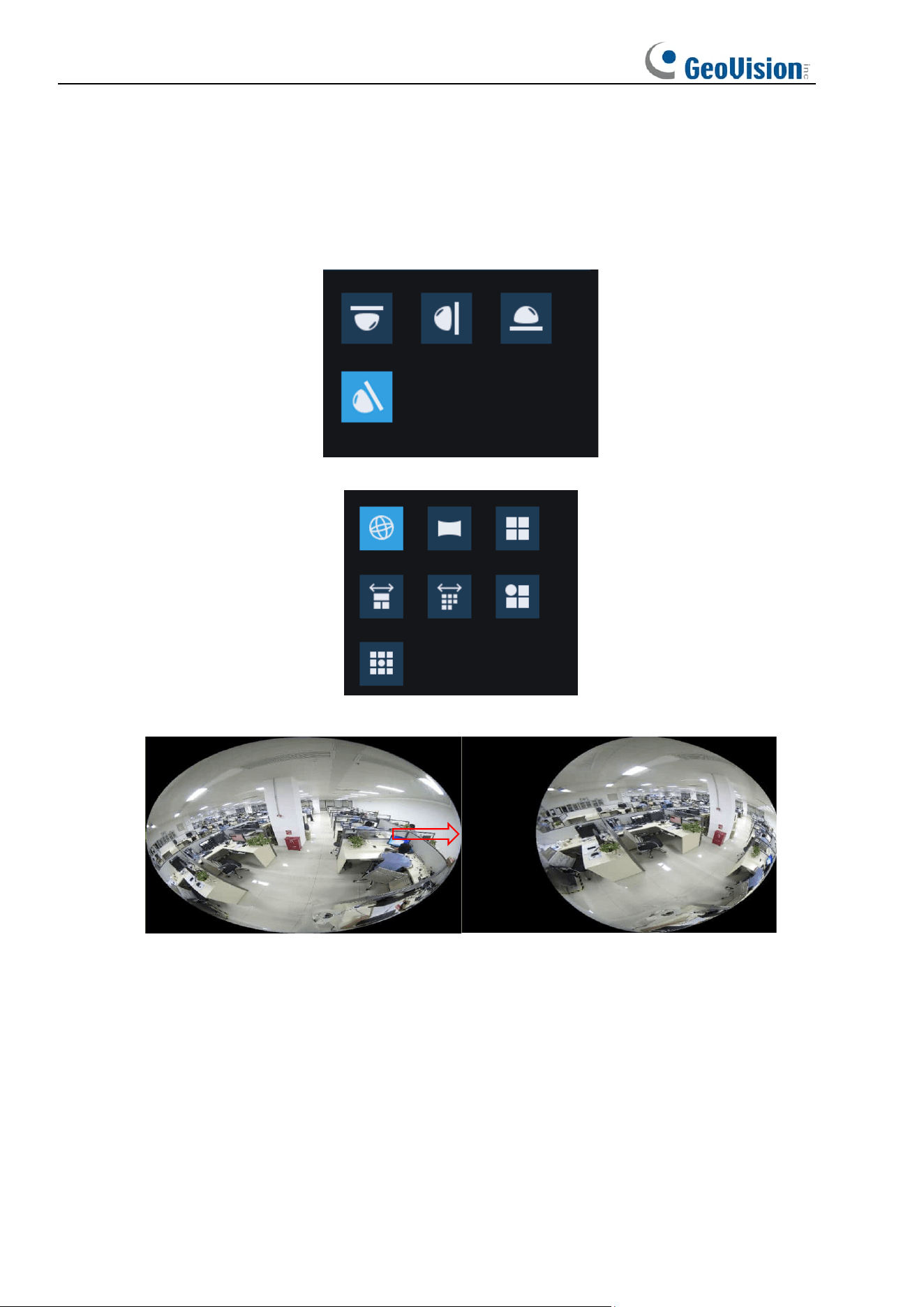
Fisheye: Used to select the fisheye dewarping display method and installation method.
Add Tag: Users can click the icon to add tags.
Popup Info: The current alarm is displayed at the lower right corner.
22
Note: Fisheye dewarping is only applicable on Internet Explorer or Internet Explorer mode
on Microsoft Edge.
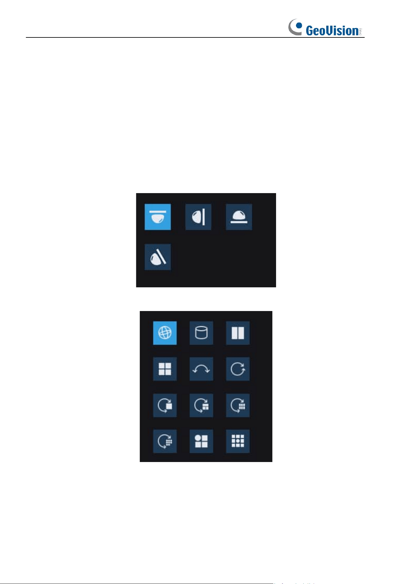
6.1.1 Fisheye Correction
The fisheye correction module in this document refers specifically to the fisheye soft
correction method, the installation mode and the display mode, as shown in the figure. Click
the Fisheye icon at the bottom tool bar to access the options. Note that this is only
applicable to GV-RFER12700 on Internet Explorer.
Installation method: Installation modes, support for ceiling, wall, desktop, tilt four installation
modes, in different installation scenarios, you can choose with the appropriate calibration
mode to achieve the best results.
Display Method: Display modes, including: fisheye image, 360-degree panorama,
180-degree panorama, PTZ image, 3D cylindrical and VR modes, as well as combinations of
the above modes with each other, the display modes will be different depending on the
installation mode.
Calibration for Soft Solution
Fisheye image: Full-view/wide-angle images obtained through a fisheye lens.
Panoramic image: Fisheye image corrected to a rectangular image.
PTZ image: Corrected close-up image of a selected area in a fisheye/panorama image.
3D Column image: Fisheye image corrected, 3D image in the form of a cylinder.
23
VR image: Presented in the form of 3D fisheye correction image, using the mouse to drag
and drop the operation to change the viewing angle, the use of the scroll wheel can be
gradually zoomed in on the view of the image, when the mouse selects a certain area,
double-click on the right button of the mouse, you can roam to the corresponding area and
present the PTZ image of the region.
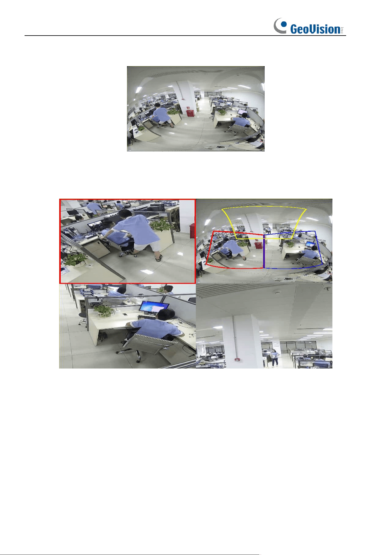
6.1.1.1 Ceiling
Function Description:
Ceiling mode, i.e., fisheye camera mounted on the ceiling and other scenes that require an
overhead view, as shown below:
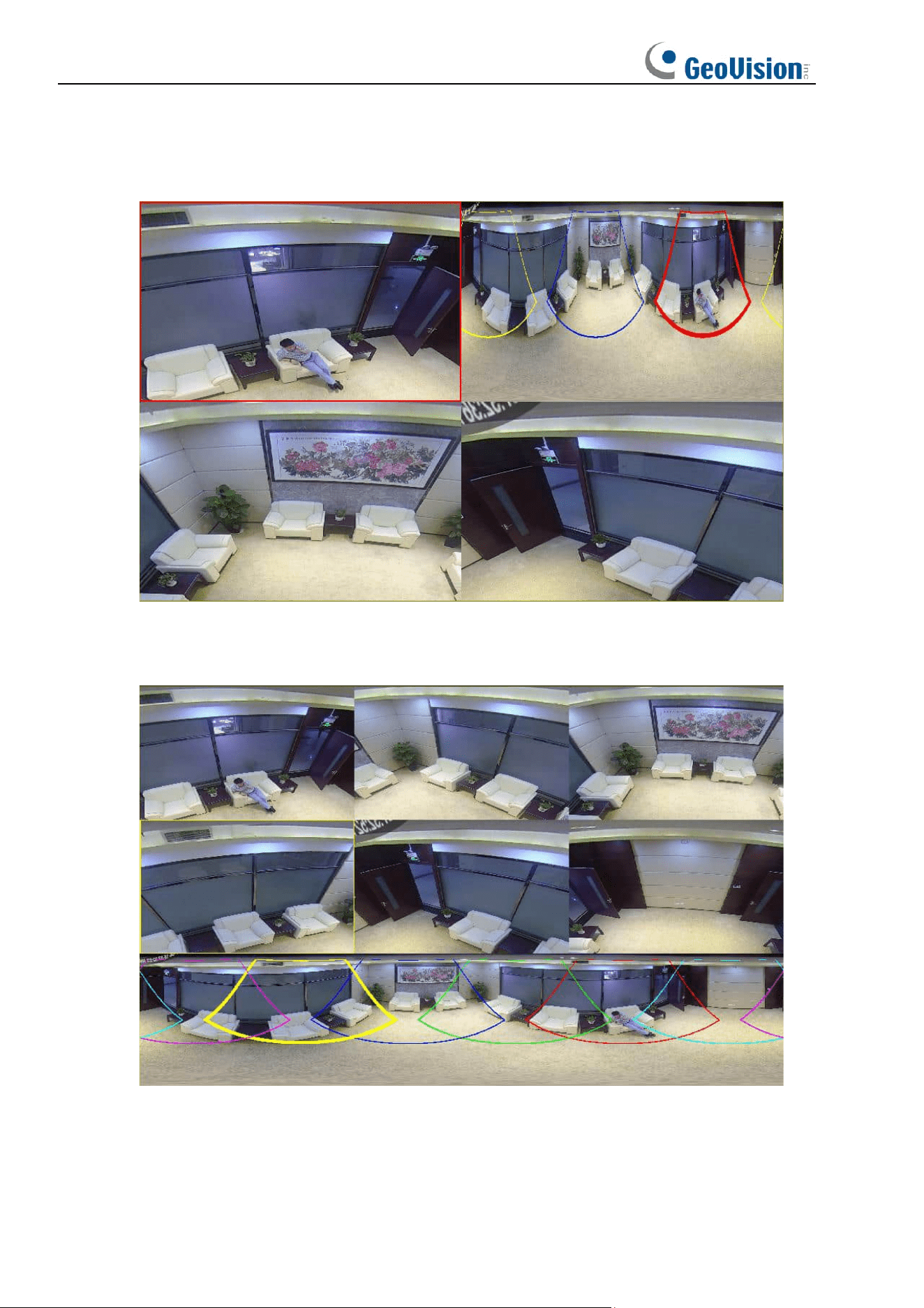
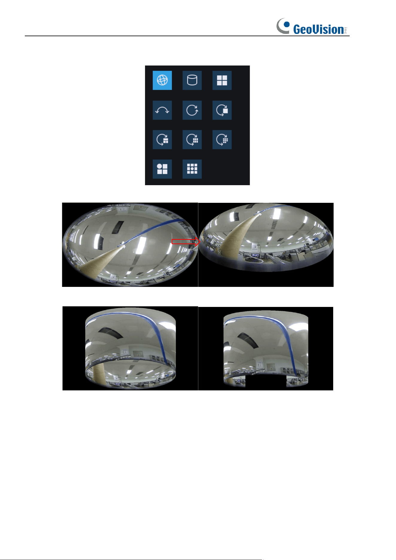
There are a total of 12 displays in this installation mode, as shown below:
24
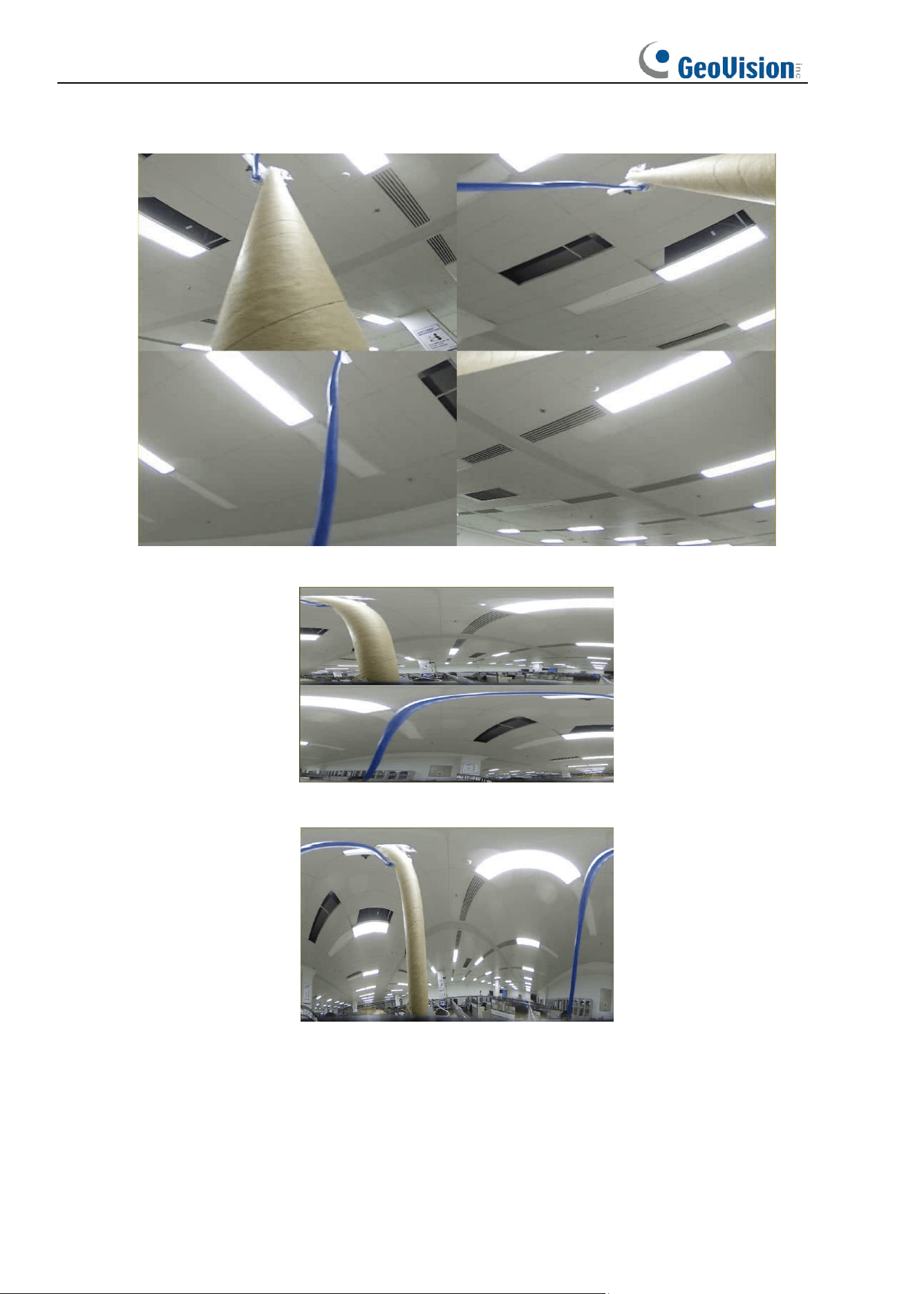
1. VR mode (Double right-click to roam, as shown below)
2. 3D Cylinde (Cylinder, as shown below)
3. 2PTZ
4. 4PTZ
25
5. 180 Panorama View
6. 360 Panorama View
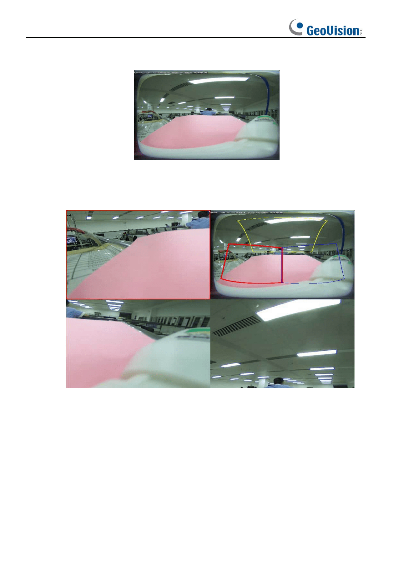
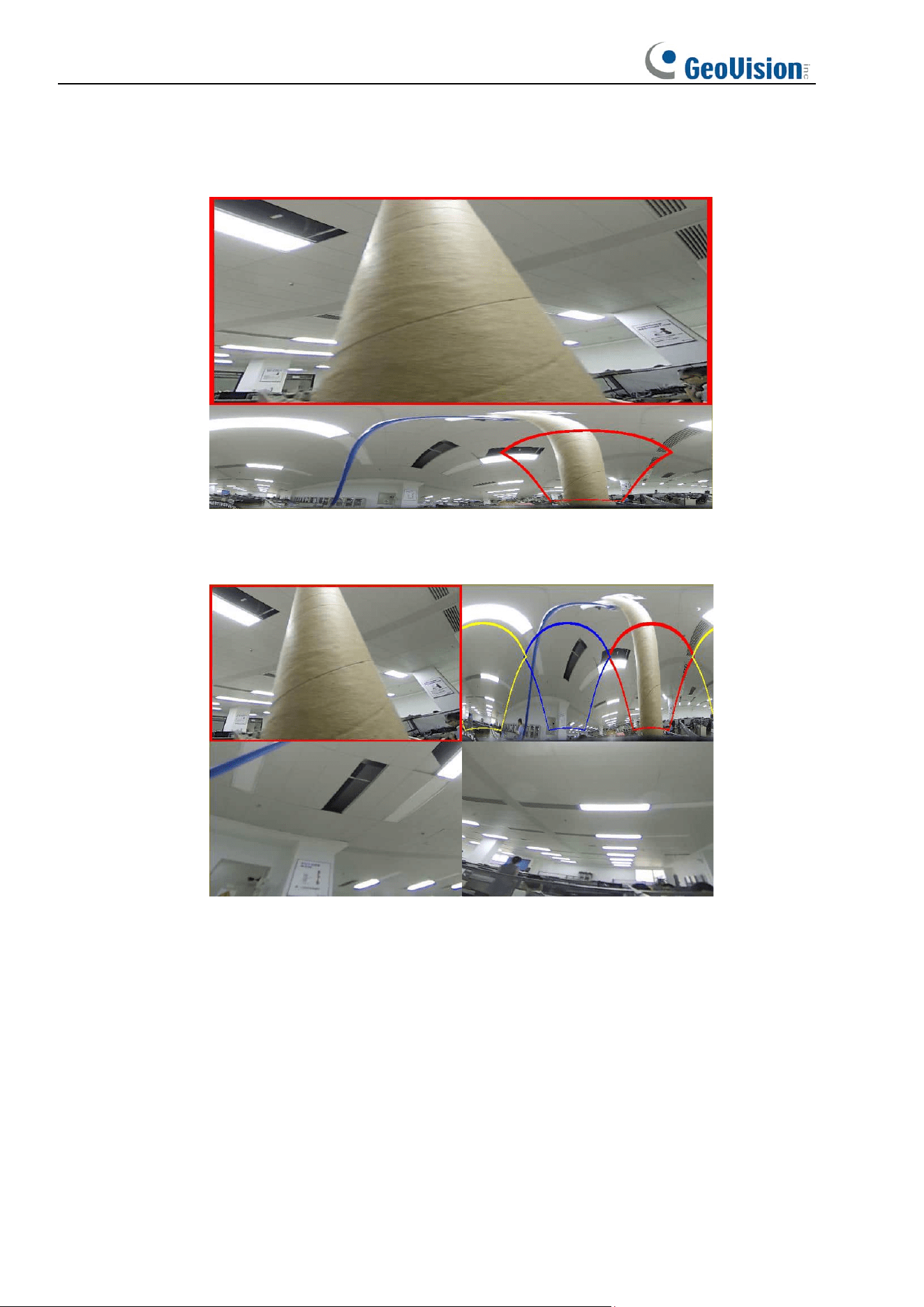
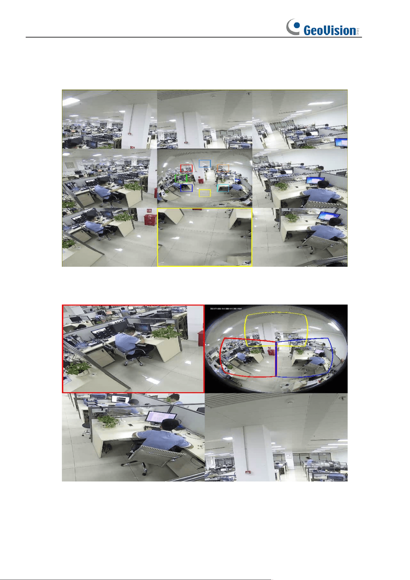
7. 360 Panorama and 1PTZ (On the panoramic image, different color areas represent
different PTZ viewing angle ranges, and by selecting the corresponding PTZ drawing line
range, you can also drag the inverse to change its viewing angle position)
26
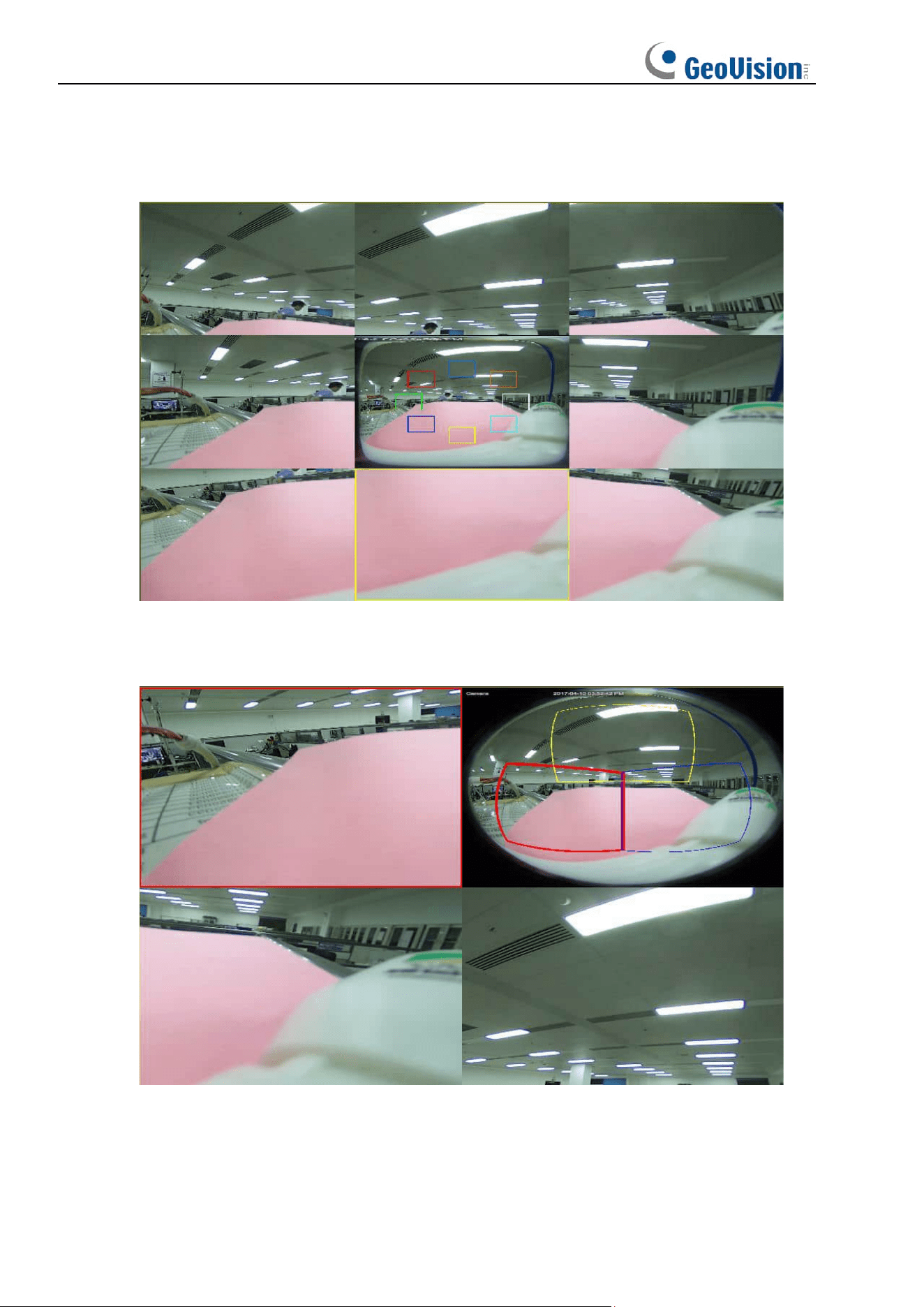
8. 360 Panorama and 3PTZ (On the panoramic image, different color areas represent
different PTZ viewing angle ranges, and by selecting the corresponding PTZ drawing line
range, you can also drag the inverse to change its viewing angle position)
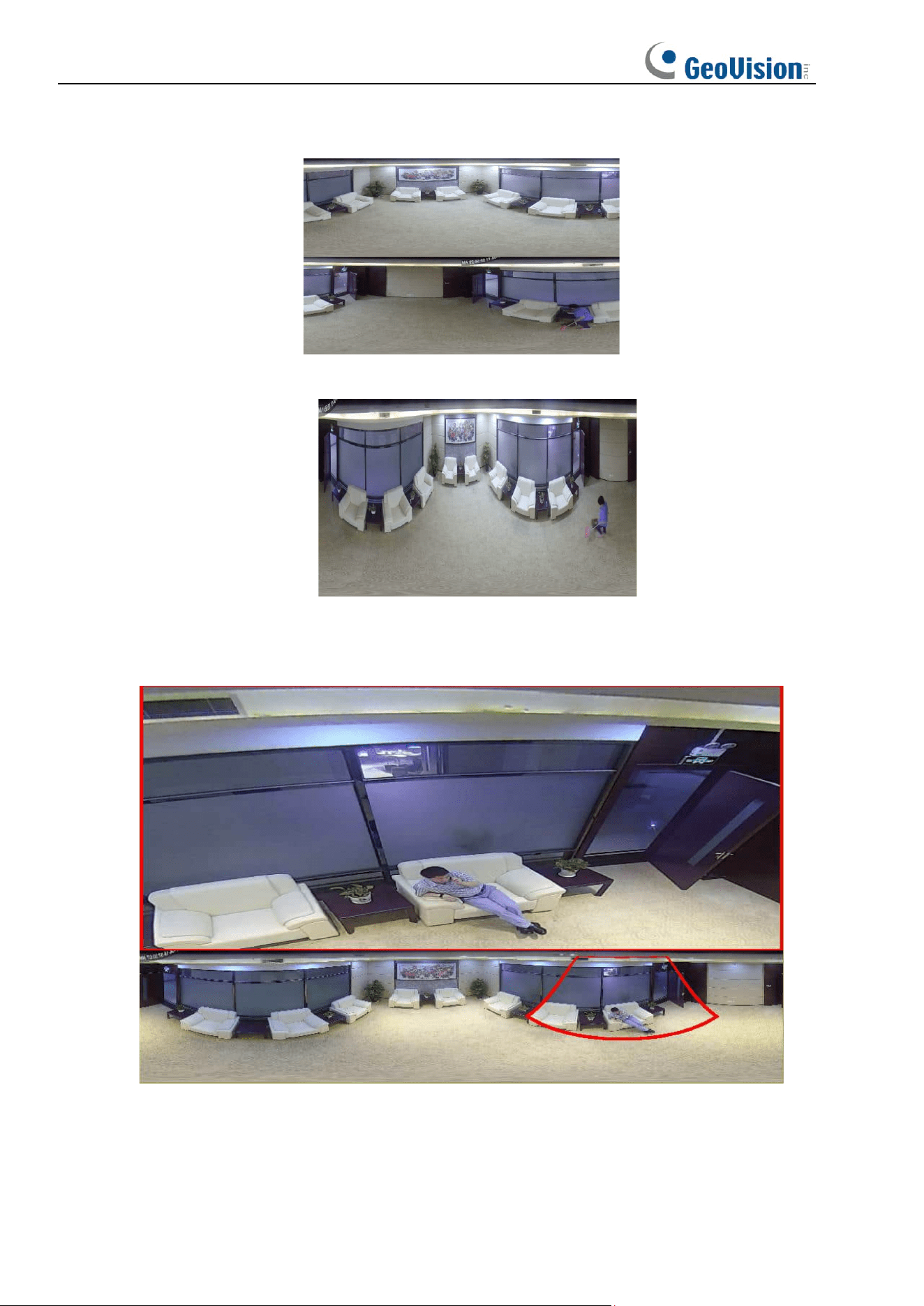
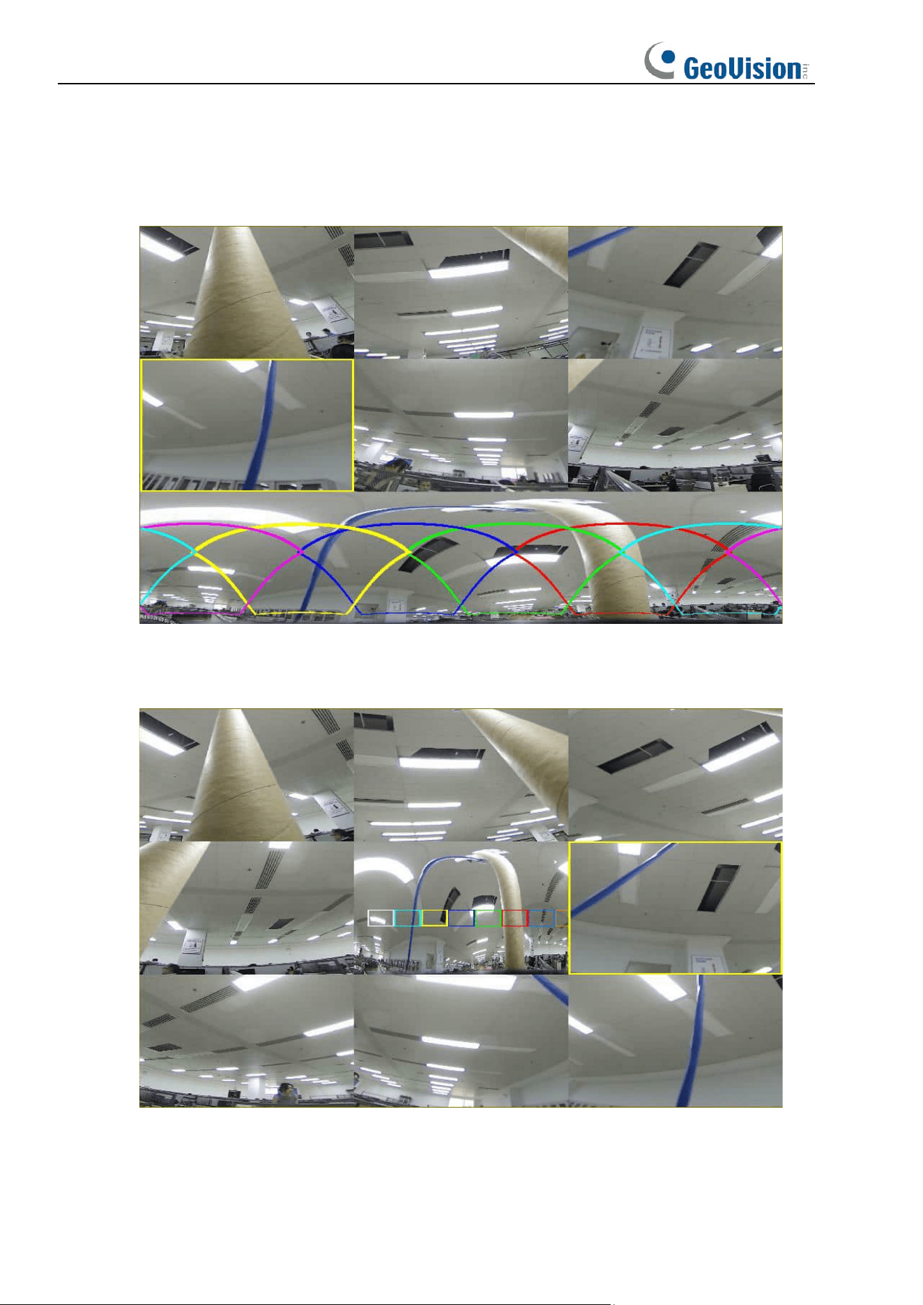
9. 360 Panorama and 6PTZ (On the panoramic image, different color areas represent
different PTZ viewing angle ranges, and by selecting the corresponding PTZ drawing line
range, you can also drag the inverse to change its viewing angle position)
27
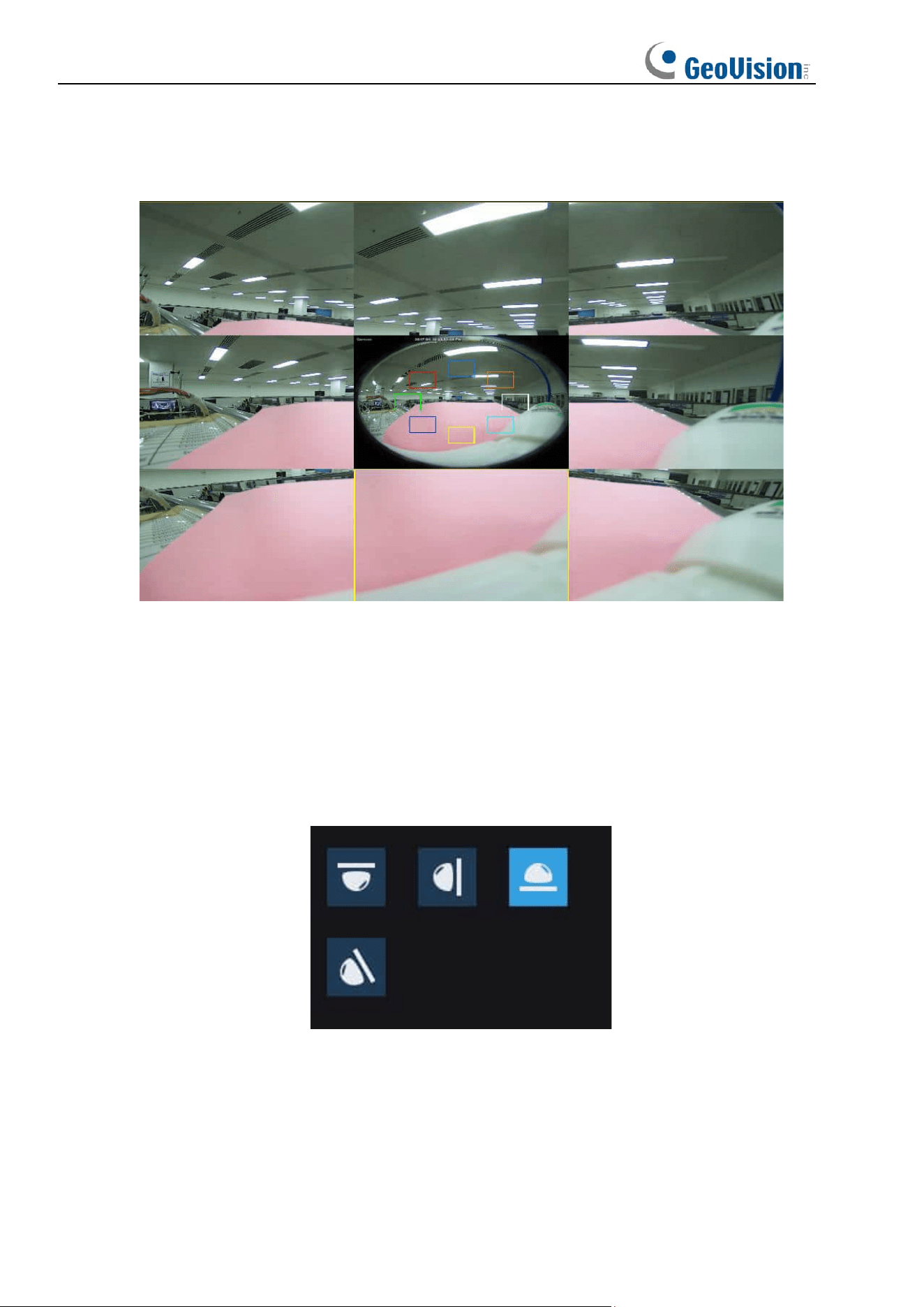
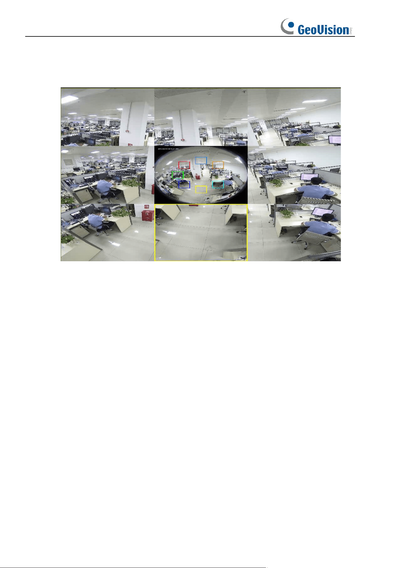
10. 360 Panorama and 8PTZ (On the panoramic image, different color areas represent
different PTZ viewing angle ranges, and by selecting the corresponding PTZ drawing line
range, you can also drag the inverse to change its viewing angle position)
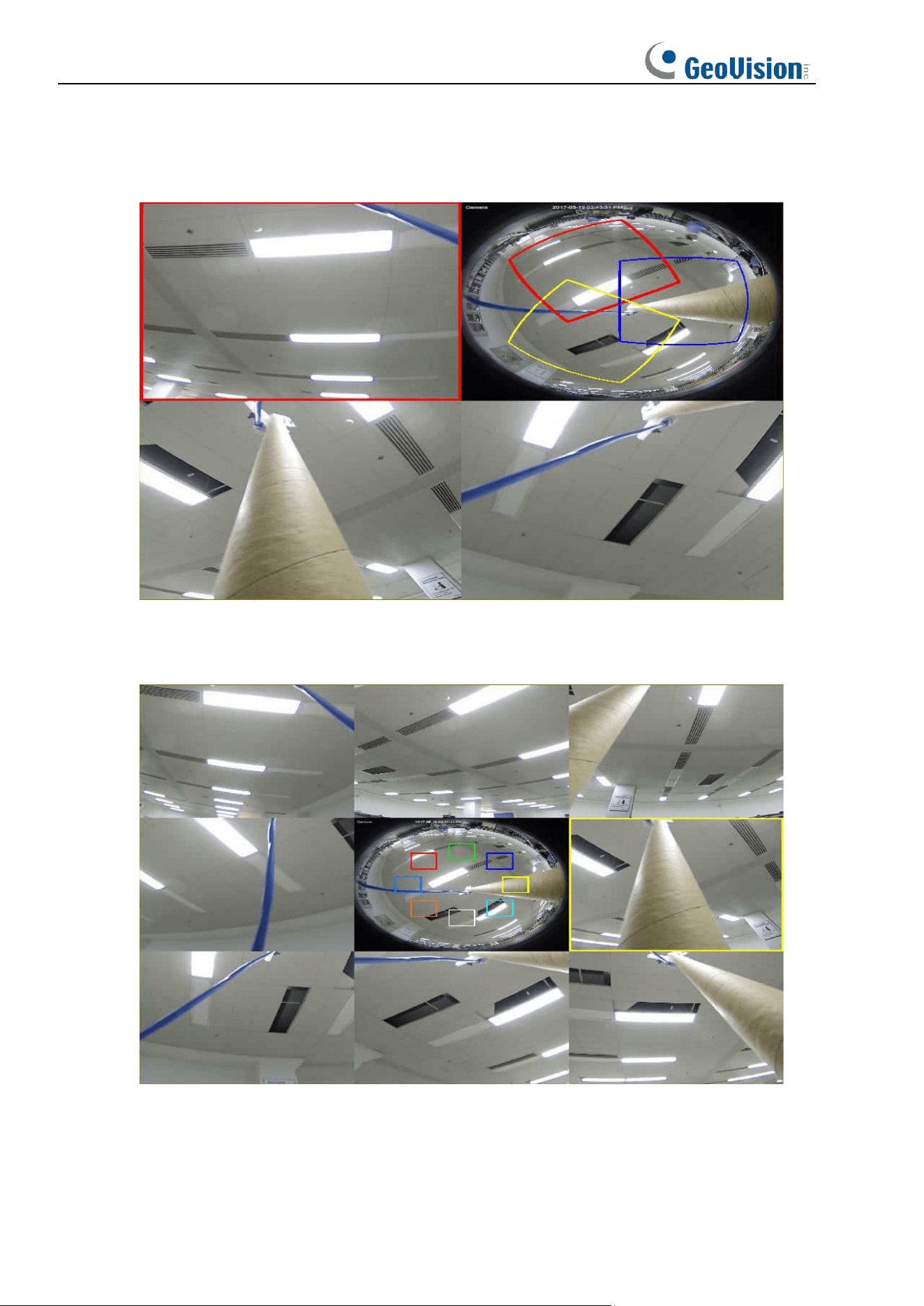
11. Fisheye and 3PTZ (On the fisheye image, different color areas represent different PTZ
viewing angle ranges, and by selecting the corresponding PTZ drawing line range, you
can also drag the inverse to change its viewing angle position)
28
12. Fisheye and 8PTZ (On the panoramic image, different color areas represent different
PTZ viewing angle ranges, and by selecting the corresponding PTZ drawing line range,
you can also drag the inverse to change its viewing angle position)
29
6.1.1.2 Wall
Function Description:
Wall mounting mode, i.e. scenarios where the fisheye camera is mounted on a vertical
surface such as a wall, as shown below.
There are seven display modes in this installation mode, as shown below.
1. VR Mode
30
2. Normal Panorama View
3. 4PTZ
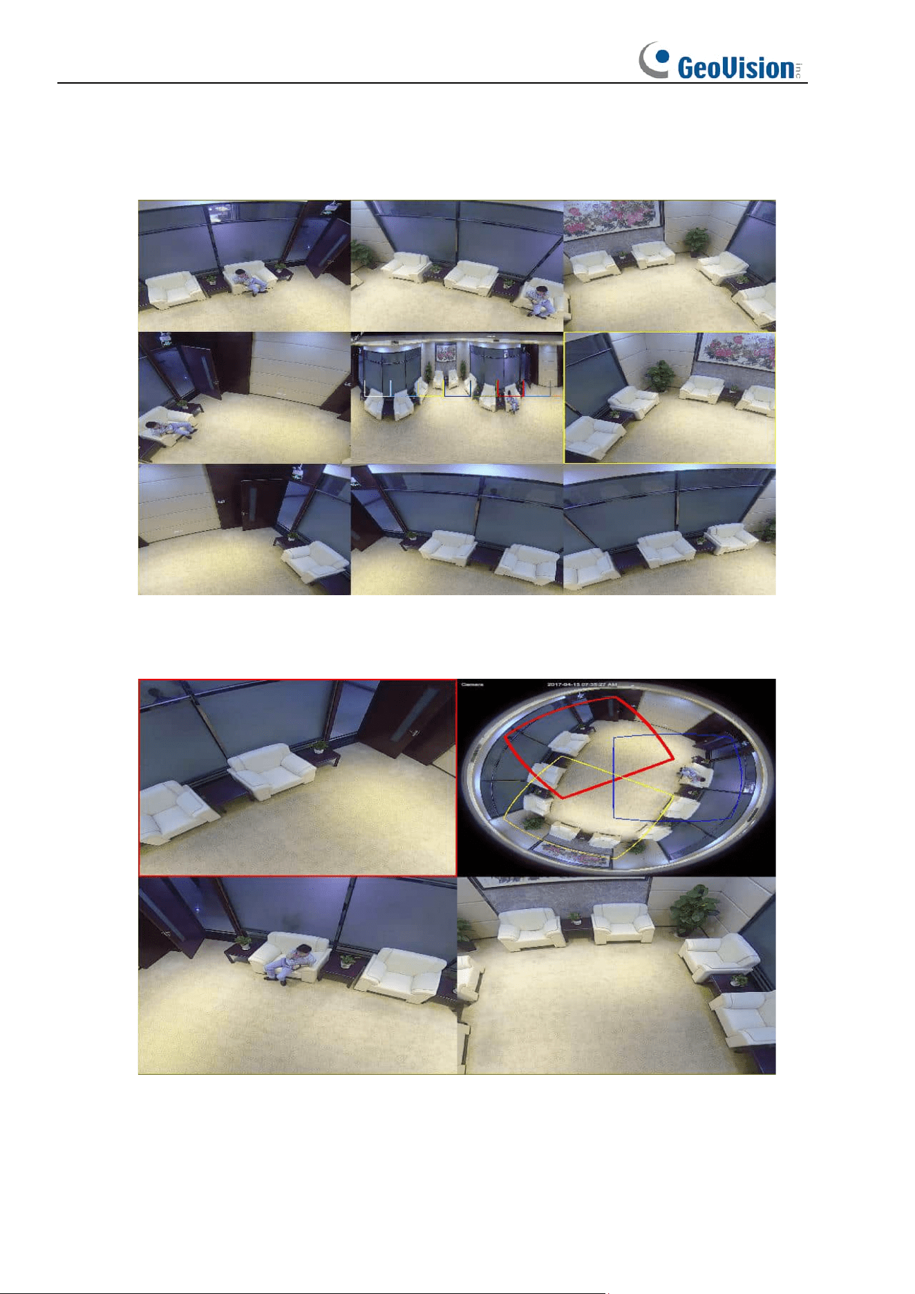
4. Panorama and 3PTZ (On the panoramic image, different color areas represent different
PTZ viewing angle ranges, and by selecting the corresponding PTZ drawing line range,
you can also drag the inverse to change its viewing angle position)
31
5. Panorama and 8PTZ (On the panoramic image, different color areas represent different
PTZ viewing angle ranges, and by selecting the corresponding PTZ drawing line range,
you can also drag the inverse to change its viewing angle position)
6. Fisheye and 3PTZ (On the fisheye image, different color areas represent different PTZ
viewing angle ranges, and by selecting the corresponding PTZ drawing line range, you
can also drag the inverse to change its viewing angle position)
32
7. Fisheye and 8PTZ (On the fisheye image, different color areas represent different PTZ
viewing angle ranges, and by selecting the corresponding PTZ drawing line range, you
can also drag the inverse to change its viewing angle position)
6.1.1.3 Desktop
Function Description:
Desktop mounting mode, i.e. fisheye camera mounted on the desktop/floor, etc., which
requires elevated view, as shown below.
Application Scenario: Desktop video-conferencing.
33
There are 11 display modes in this installation mode, as shown below.
1. VR Mode
2. 3D Cylinder
34
3. 4PTZ
4. 180 Panorama View (180 Panorama View)
5. 360 Panorama View
35
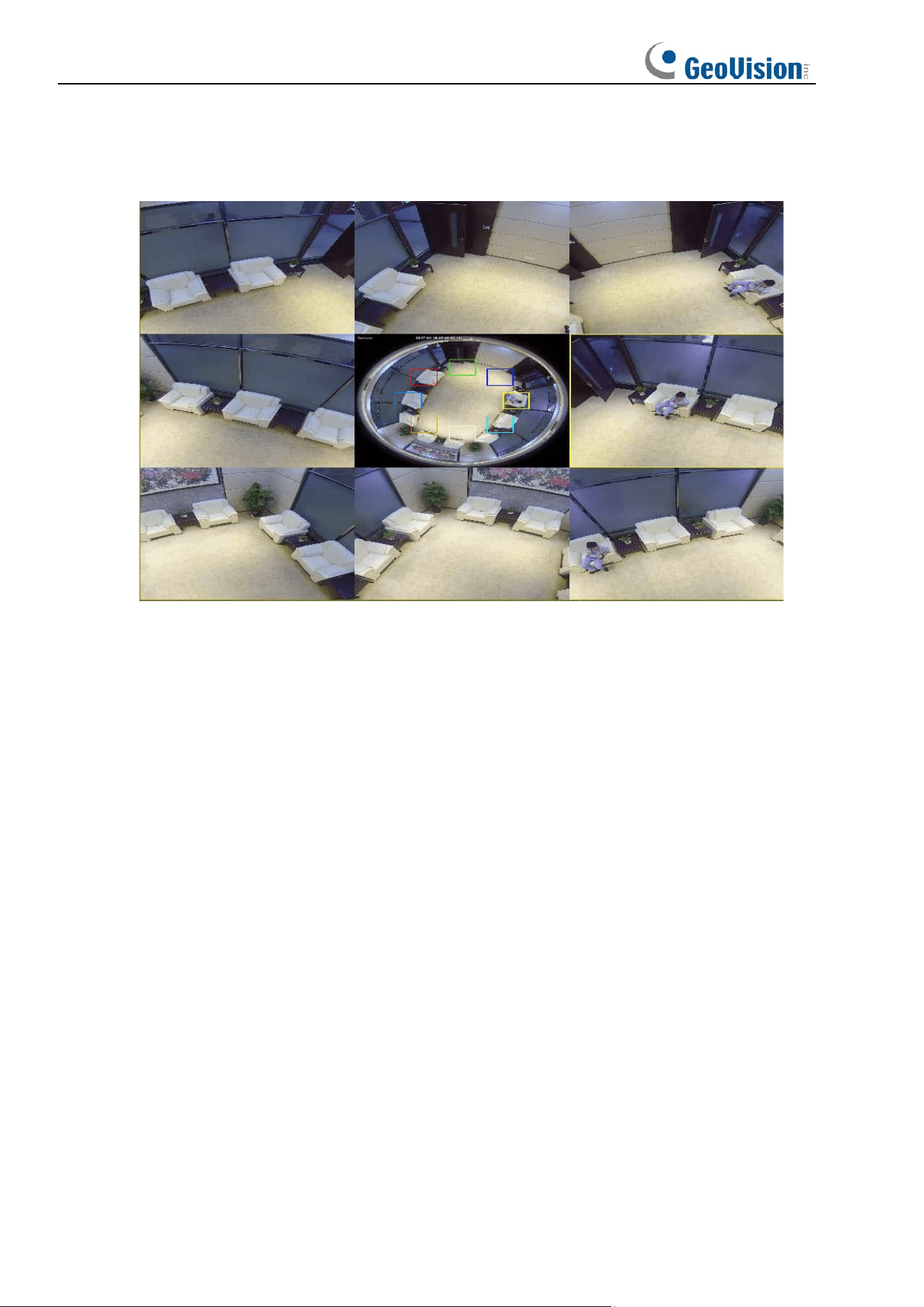
6. 360 Panorama and 1PTZ (On the panoramic image, different color areas represent
different PTZ viewing angle ranges, and by selecting the corresponding PTZ drawing line
range, you can also drag the inverse to change its viewing angle position)
7. 360 Panorama and 3PTZ (On the panoramic image, different color areas represent
different PTZ viewing angle ranges, and by selecting the corresponding PTZ drawing line
range, you can also drag the inverse to change its viewing angle position)
36
8. 360 Panorama and 6PTZ (On the panoramic image, different color areas represent
different PTZ viewing angle ranges, and by selecting the drawing line range
corresponding to the PTZ, you can also drag the reverse to change its viewing angle
position)
9. 360 Panorama and 8PTZ (On the panoramic image, different color areas represent
different PTZ viewing angle ranges, and by selecting the corresponding PTZ drawing line
range, you can also drag the inverse to change its viewing angle position)
37
10. Fisheye and 3PTZ (On the fisheye image, different color areas represent different PTZ
viewing angle ranges, and by selecting the corresponding PTZ drawing line range, you
can also drag the inverse to change its viewing angle position)
11. Fisheye and 8PTZ (On the fisheye image, different color areas represent different PTZ
viewing angle ranges, and by selecting the corresponding PTZ drawing line range, you
can also drag the inverse to change its viewing angle position)
38
6.1.1.4 Tilt
Function Description:
Tilt mounting mode, i.e., the fisheye camera is mounted in a scenario where it is at an angle of
approximately 25° to a vertical surface such as a wall, as shown 1-2-4-1.
Application Scenario: Corner where two walkways/roads etc. Meet.
There are 8 display modes in this installation mode, as shown below.
1. VR Mode
39
2. Normal Panorama View
3. 4PTZ
4. Panorama and 3PTZ (On the panoramic image, different color areas represent different
PTZ viewing angle ranges, and by selecting the corresponding PTZ drawing line range,
you can also drag the inverse to change its viewing angle position)
40
5. Panorama and 8PTZ (On the panoramic image, different color areas represent different
PTZ viewing angle ranges, and by selecting the corresponding PTZ drawing line range,
you can also drag the inverse to change its viewing angle position)
6. Fisheye and 3PTZ (On the fisheye image, different color areas represent different PTZ
viewing angle ranges, and by selecting the corresponding PTZ drawing line range, you
can also drag the inverse to change its viewing angle position)
41
7. Fisheye and 8PTZ (On the fisheye image, different color areas represent different PTZ
viewing angle ranges, and by selecting the drawing line range corresponding to the PTZ,
you can also drag the reverse to change its viewing angle position)
42
6.2 Recording Status
The recording status is a simple presentation of the current alarm at the web client and
indicates whether the recording is normal. A variety of alarms can be stored at a time, as
described below:
No icon: The memory card functions normally but no recording is executing.
: The camera is normally recording.
Note: When the camera is recording an alarm, the icon disappears, but the normal recording
process continues.
: The memory card is abnormal. Check the memory card.
: A motion alarm is in progress but the motion alarm recording is not turned on.
: A motion alarm is in progress and the motion alarm recording is turned on.
: An I/O alarm is in progress, but the I/O alarm recording is not turned on.
: An I/O alarm is in progress, and the I/O alarm recording is turned on.
: An intelligent alarm is in progress, but the intelligent alarm recording is not turned on.
Note: Intelligent alarms include face, human, and vehicle alarms.
: An intelligent alarm is in progress, and the intelligent alarm recording is turned on.
43
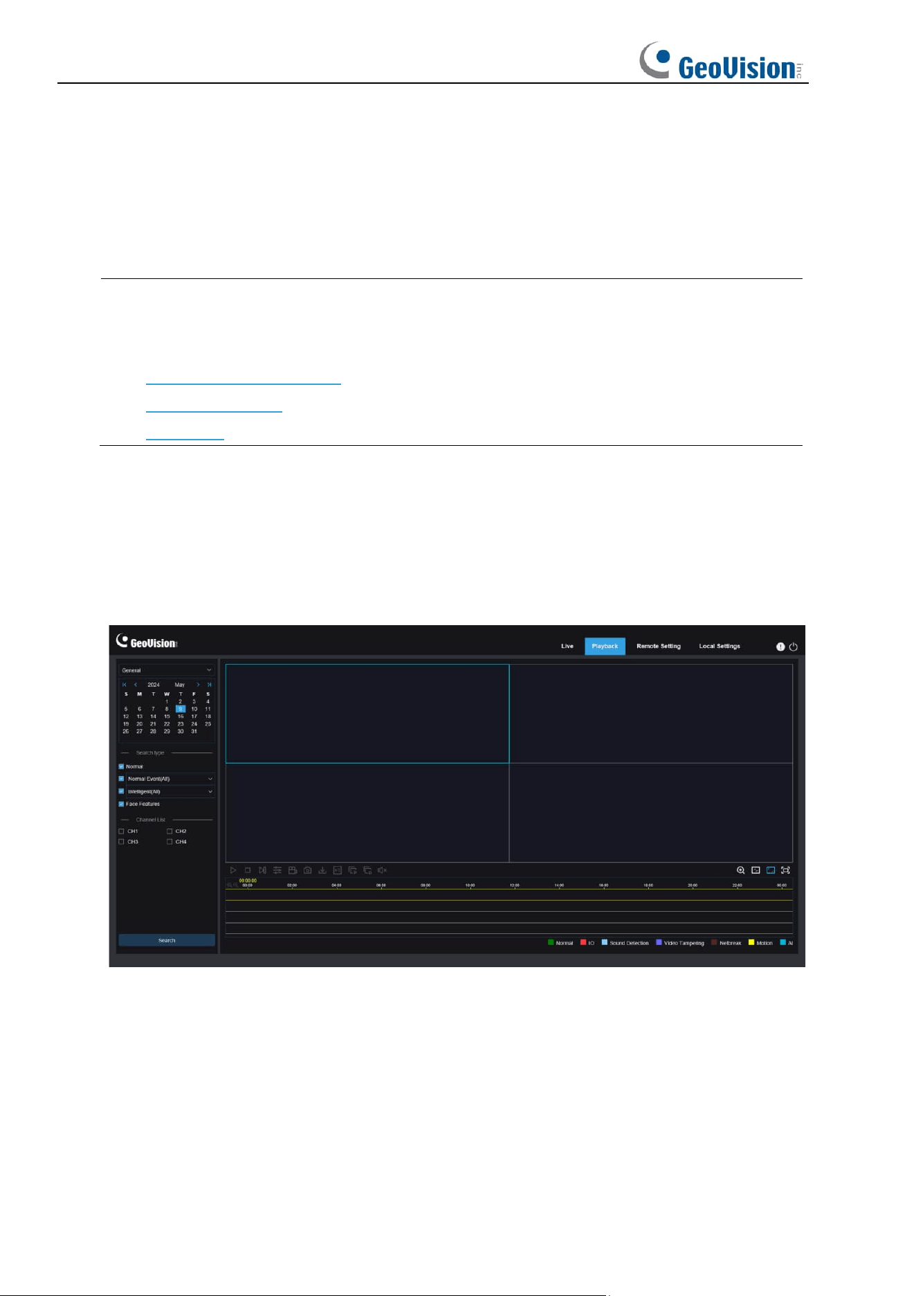
7 Playback
The camera not only need to be able to show us images in real time, but also save the image
information so that we can call it up when needed.
Note: To play the exported video clips on your PC, install and launch one of the following
players before locating the recordings. Wait for 3 ~ 30 seconds before the video starts to
play.
1. GV-R Series Video Player
2. VLC Media Player
3. KM Player
7.1 Normal Playback
The playback function mainly includes general video search and AI search, as shown in the
following figure.
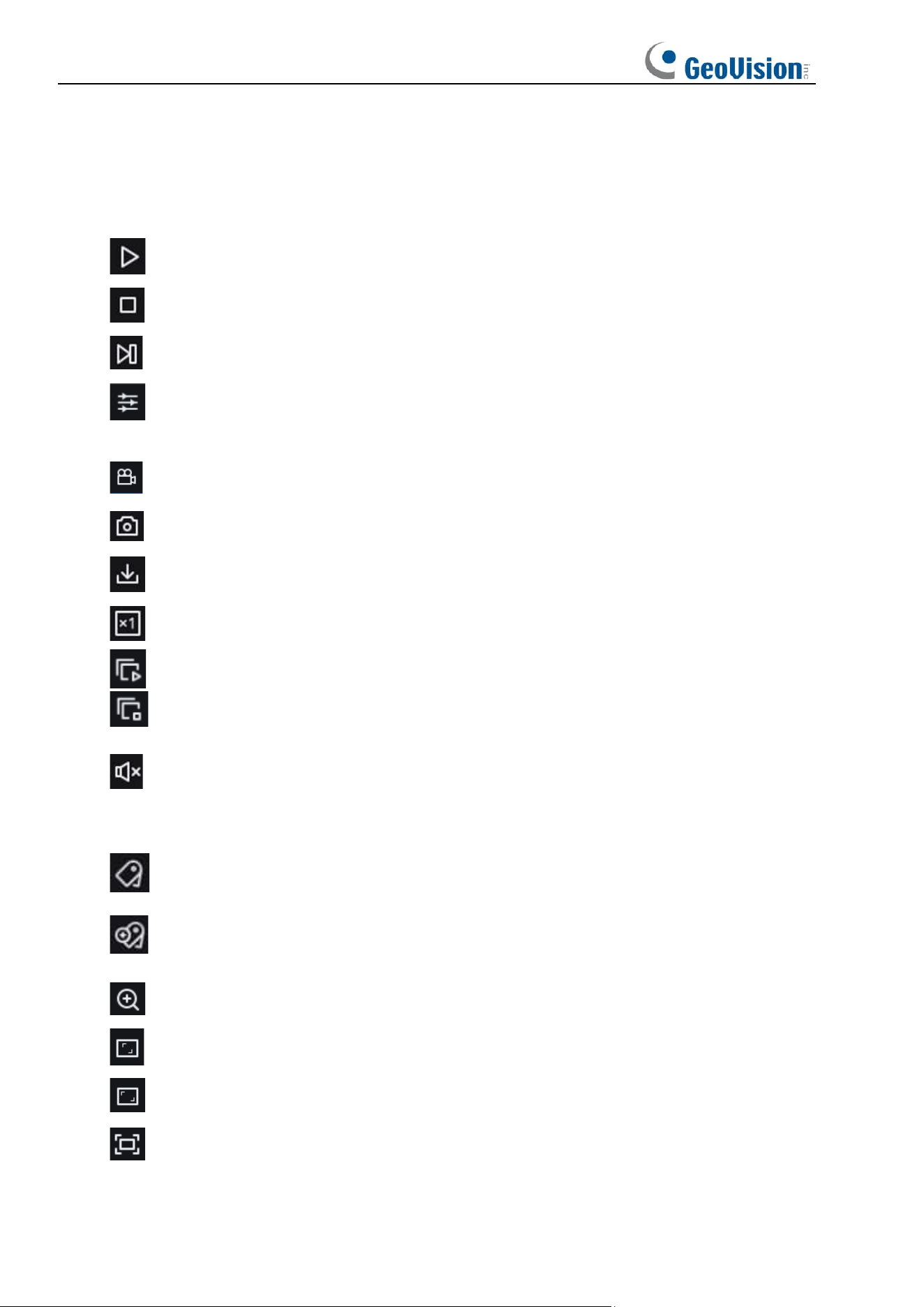
Search Mode switching: Used to switch search functions, as shown in the figure above.
General is selected by default to search for general recording files. You can switch to AI image
search by referring to the following part in this section.
Date: Used to set the date to search for recording files. Click Search. You will be prompted
with the dates with available recording files.
Search type: Displays the search types supported by the camera. You can search for only
part of recording files as required.
44
Channel selection: Enables users to select channels to search for (only applicable to
GV-RMS32810).
Search: Display and search for recording files stored in the memory card according to search
settings.
Pause/Play: Used to pause/play streams.
Stop: Used to stop streams.
Forward by One Frame: Used to play one frame with one click.
Synchronous Playback: Used to play back recording files in four channels at a time
(only applicable to GV-RMS32810).
Record: Used to manually record the stream in preview.
Capture: Used to manually capture the image of the current stream.
Download: Download the searched recording file.
Speed: Supports playing at a speed of 1/8, 1/4, 1/2, 1, X2, X4, and X8.
Play All: Used to play recording files in all channels (only applicable to GV-RMS32810).
Stop All: Used to stop recording files in all channels (only applicable to
GV-RMS32810).
Audio: Used to turn on/off or adjust stream sound.
Playback progress bar: The time bar on the bottom displays the current playback progress
bar and playback progress in different colors based on the search results.
Add Default Tag: Used to add default tags. Mark the current time of the current
channel as the playback start time, and click the icon to add tags.
Add Tag: Used to add custom tags. Click Add Tag. The Custom window appears.
Users can name tags.
Digital Zoom: Used to zoom in a certain area of the stream.
Original Proportions: Displays the current live view in its original proportion.
Stretch: Displays the current live view in a way that stretches the display area.
Full Screen: Displays the playback stream in full screen. You can double-click the
screen to enable or disable the function, and press Esc to exit the full screen mode.

45
Zooming in/out playback progress bar: By default, the progress bar displays the progress
within 24 hours. By zooming in and out the progress bar, you can jump to the corresponding
playback position more accurately. You can also use the mouse wheel to zoom in/out the
progress bar.
46
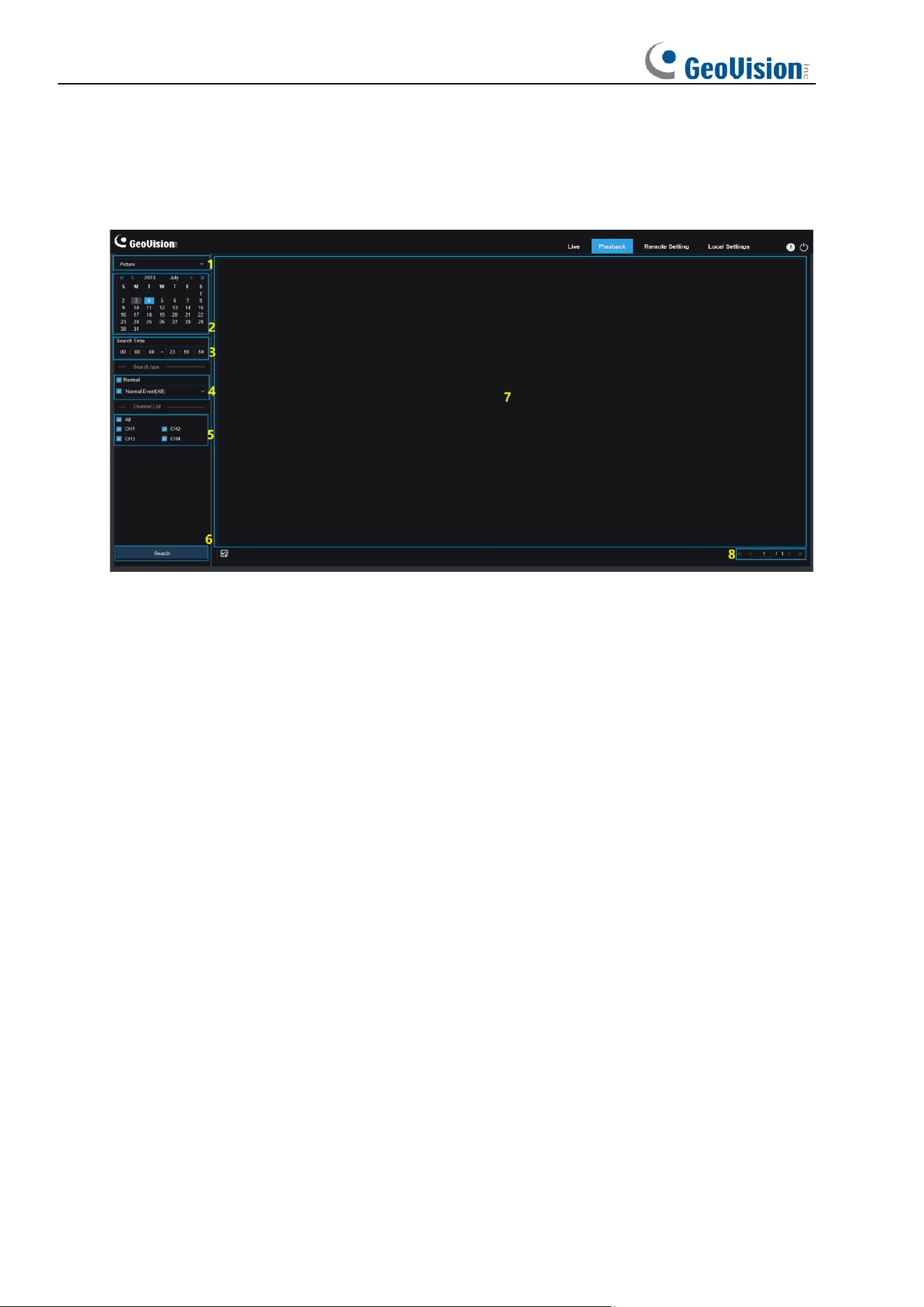
7.2 Image Search
When the auto capture function is enabled, you can search and play pictures on this screen.
1. Search Mode switching: Used to switch the current search function. The current Search
Mode is Picture.
2. Date: Used to set the date to search for pictures. By clicking Search, you will be
prompted with the dates for which recording files are available.
3. Search time: Used to set the time to search for pictures, allowing users to search for
pictures in a specific period of time.
4. Search type: Used to select the picture capture type you want to search for, or check "All
Type" to select all pictures.
5. Channel Selection: Enables users to select channels to search for (only applicable to
GV-RMS32810).
6. Search: Click Search to start searching images.
7. Search Result Display Area: Displays the desired search results. Double-click on a
picture will play the video after and before the picture.
8. Search Result Scrolling Through: You can scroll through search results at the lower
right corner.
47
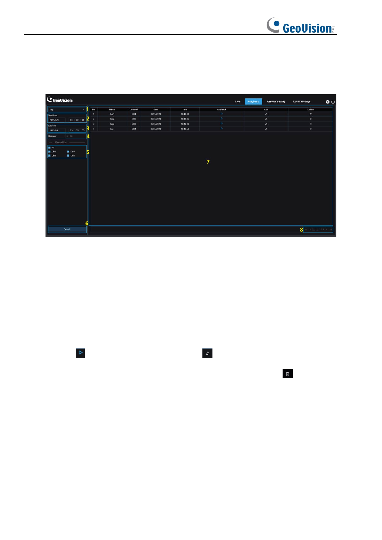
7.3 Playback by Tag
This screen allows you to view all previously added tags and edit, play back, or delete them.
1. Search Mode switching: Used to switch the current search function. The current Search
Mode is Tag.
2. Start time: Used to set the start time to search for tags.
3. End time: Used to set the end time to search for tags.
4. Keyword: You can search for tags with keywords.
5. Channel Selection: Enables users to select channels to search for (only applicable to
GV-RMS32810).
6. Search: Click Search to start searching.
7. Search Result Display Area: Displays the desired search results.
Click the button to play back events, click the button to change event name, click the
Save button to display the Modify Success prompt dialog box, and click the button to
delete this event.
8. Search Result Scrolling Through: You can scroll through search results at the lower
right corner.
48
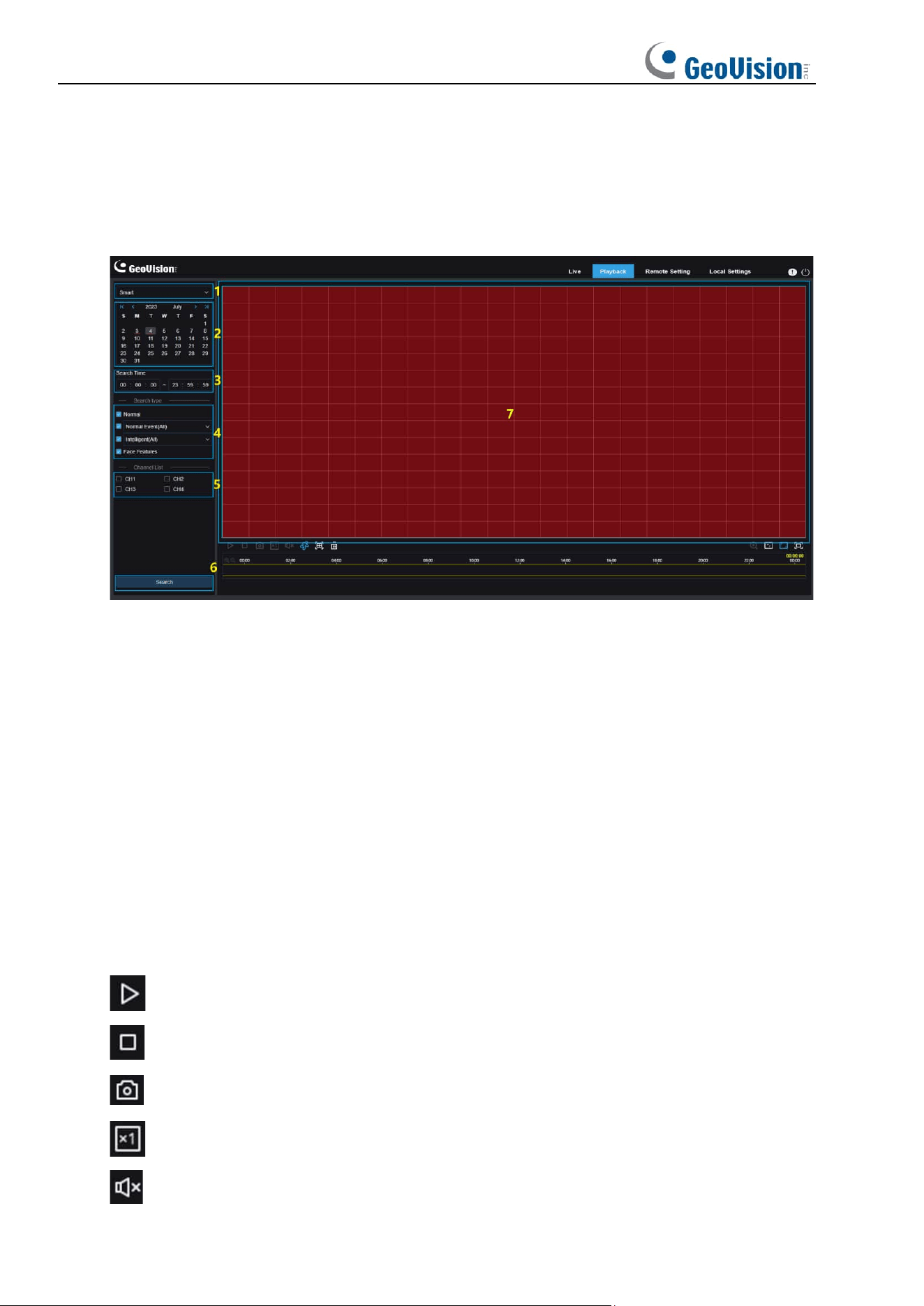
7.4 Smart
Log in from a browser without the need of plugin to start smart playback, as shown in the
figure below:
This function can identify whether an alarm is triggered by human in daily life. If it is, the alarm
will be shown in blue in the playback time bar on the bottom.
1. Search Mode switching: Used to switch the current search function. The current Search
Mode is Smart.
2. Date: Used to set the date to search for smart events. By clicking Search, you will be
prompted with the dates for which recording files are available.
3. Search time: Used to set the time for searching for events to facilitate querying.
4. Search type: Displays the search types supported by the camera. You can search for
only part of recording files as required.
5. Channel Selection: Enables users to select channels to search for (only applicable to
GV-RMS32810).
6. Search: Click Search to start searching.
7. Search Result Display Area: Displays the desired search results.
Pause/Play: Used to pause/play streams.
Stop: Used to stop streams.
Capture: Used to manually capture the image of the current stream.
Speed: Supports playing at a speed of 1/8, 1/4, 1/2, 1, X2, X4, X8, and X16.
Audio: Used to turn on/off or adjust stream sound.
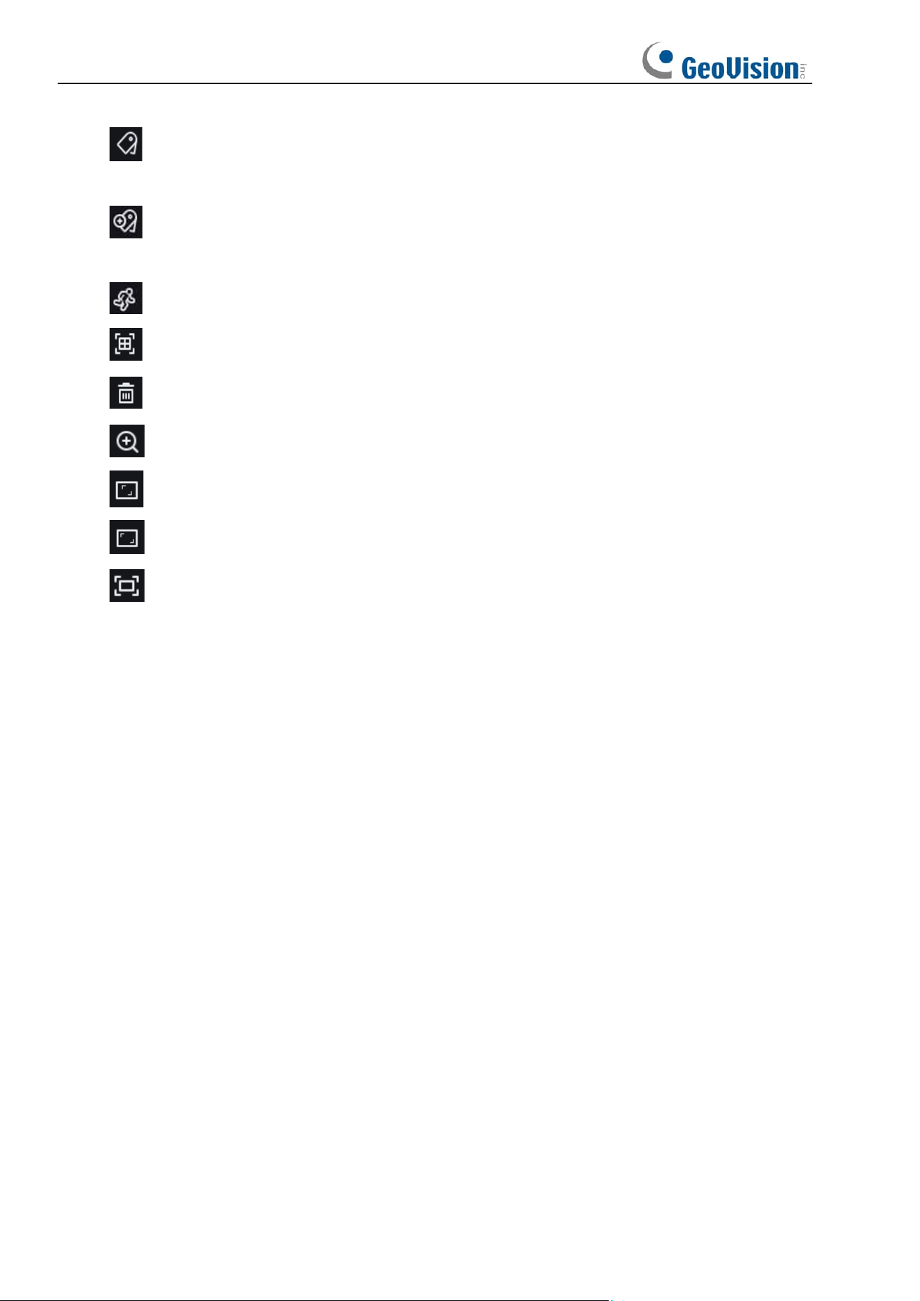
49
Add Default Tag: Used to add default tags. Mark the video playback start time at the
current time in the current channel and click this icon to add tags.
Add Tag:
Used to add custom tags. When you click this icon to add a tag, a custom
window appears and you can specify a name for this tag.
Smart:
You can click this icon to enter the Smart area setting screen.
All: Click on All will set the full screen as the Smart detection area.
Delete: Click on Delete All will clear the entire area.
Digital Zoom: Used to zoom in a certain area of the stream.
Original Proportions: Displays the current live view in its original proportion.
Stretch: Displays the current live view in a way that stretches the display area.
Full Screen: Displays the playback stream in full screen. You can double-click the
screen to enable or disable the function, and press Esc to exit the full screen mode.
50
7.5 AI
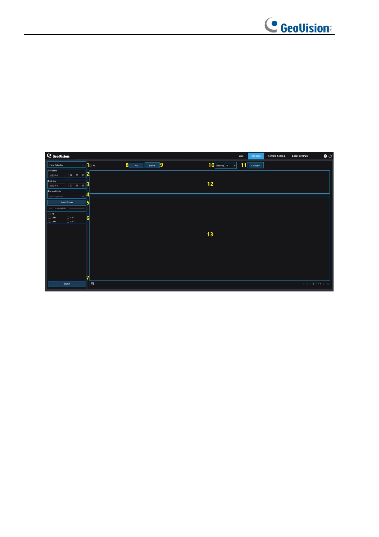
7.5.1 Face Search and Playback
The camera performs face recognition, stores the obtained face information to the SD card,
and saves the image-related information. You can quickly retrieve captured faces meeting
user requirements and easily locate corresponding videos. The face search and playback
screen are shown below.
1. Search Mode switching: Used to switch the current search function. The current
Search Mode is AI-Face Detection.
2. Start time: Used to set the start time to search for captured faces.
3. End time: Used to set the end time to search for captured faces.
4. Face Attribute: The Face Attribute box is unchecked by default. If this box is checked,
only face images captured when the face attribute detection function is started are
searched. The program can recognize five face attributes, including gender, age, mask,
glasses, and expression.
5. Alarm Group: The camera matches face images to the corresponding group according
to the settings of the face database when capturing face images. This setting allows you
to search for images of only the groups you want.
6. Channel Selection: Enables users to select channels to search for (only applicable to
GV-RMS32810).
7. Search: Used to search for face data according to settings.
8. Add: Add images to the image display area for comparison purpose. You can add local
images and captured images.
9. Delete: Used to delete currently added images.

51
10. Similarity: Used to set the lowest similarity of feature values of matching faces when
using the Compare function.
11. Compare: Search for captured faces according to the set search time, group in which
captured images are located, and selected reference face image for comparison.
12. Add Image Display Area: Displays images that are currently added and available for
comparison.
13. Search Result Display Area: On the right will display captured images searched by
using Search and Compare. Double-click on a picture will play the video after and before
the picture.
52
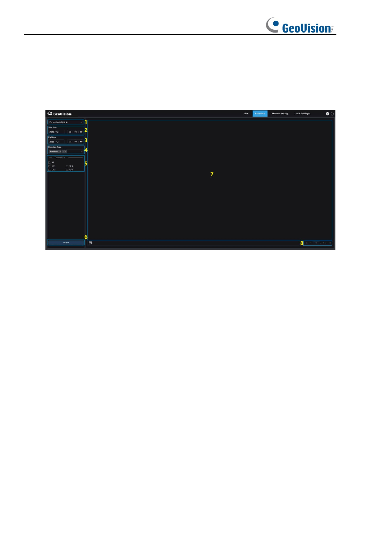
7.5.2 Pedestrian and Vehicle Search and Playback
Similar to the face capture function, the camera can distinguish pedestrians or vehicles, and
record them according to what you need to obtain required records. The screen is shown in
the figure below.
1. Search Mode switching: Used to switch the current search function. The current
Search Mode is AI-Pedestrian & Vehicle Detection.
2. Start time: Used to set the start time to search for human and vehicle images.
3. End time: Used to set the end time to search for human and vehicle images.
4. Detection Type: Used to select human or vehicle images as needed, or select both.
5. Channel Selection: Enables users to select channels to search for (only applicable to
GV-RMS32810).
6. Search: Used to search for human and vehicle images according to search settings.
7. Search Result Display Area: Displays the desired search results. Double-click on a
picture will play the video after and before the picture.
8. Search Result Scrolling Through: You can scroll through search results at the lower
right corner.
53
7.5.3 PID&LCD
With the development of technology, AI-PID&LCD can not only detect objects in the warning
area, but also provide the human and vehicle detection function that only detects human or
vehicle objects and record image or video information for easy retrieval and viewing. The
screen is shown in the figure below.
1. Search Mode switching: Used to switch the current search function. The current
Search Mode is AI-PID&LCD.
2. Start time: Used to set the start time to search for human and vehicle images.
3. End time: Used to set the end time to search for human and vehicle images.
4. Vigilance: Used to select PID or LCD or both as the capture method.
5. Detection Type: Used to select human or vehicle images as needed, or select both.
6. Channel Select: Enables users to select channels to search for (only applicable to
GV-RMS32810).
7. Search: Used to search for human and vehicle images according to search settings.
8. Search Result Display Area: Displays the desired search results. Double-click on a
picture will play the video after and before the picture.
9. Search Result Scrolling Through: You can scroll through search results at the lower
right corner.
54
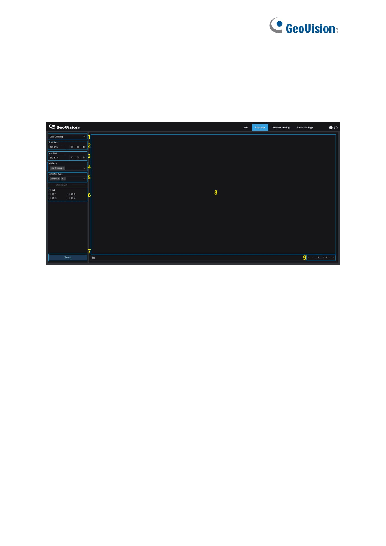
7.5.4 Intrusion
The perimeter intrusion detection function detects whether objects enter the set warning area
and triggers a linkage alarm according to the judgment. The pedestrian and vehicle detection
function is available to alarm only pedestrian or vehicle objects and record image or video
information for easy retrieval and viewing. The following figure shows the screen.
1. Search Mode Switch: Enables users to switch search modes. The currently effective
search mode is Intrusion.
2. Start Time: Used to set the time to start searching for pedestrian & vehicle images.
3. End Time: Used to set the time to end searching for pedestrian & vehicle images.
4. Vigilance: Set the capture mode triggering an alarm to Intrusion.
5. Detection Type: Used to set pedestrian and/or vehicle images to search for as needed.
6. Channel Selection: Enables users to select channels to search for (only applicable to
G-RMS32810).
7. Search: Used to search for pedestrian & vehicle images according to search settings.
8. Search Result Display Area: Displays search results. When users double click an image,
the videos recorded just before and after the time period when the image is captured will
be played.
9. Search Result Scrolling Through: Users can turn search result pages in the lower right
corner.

55
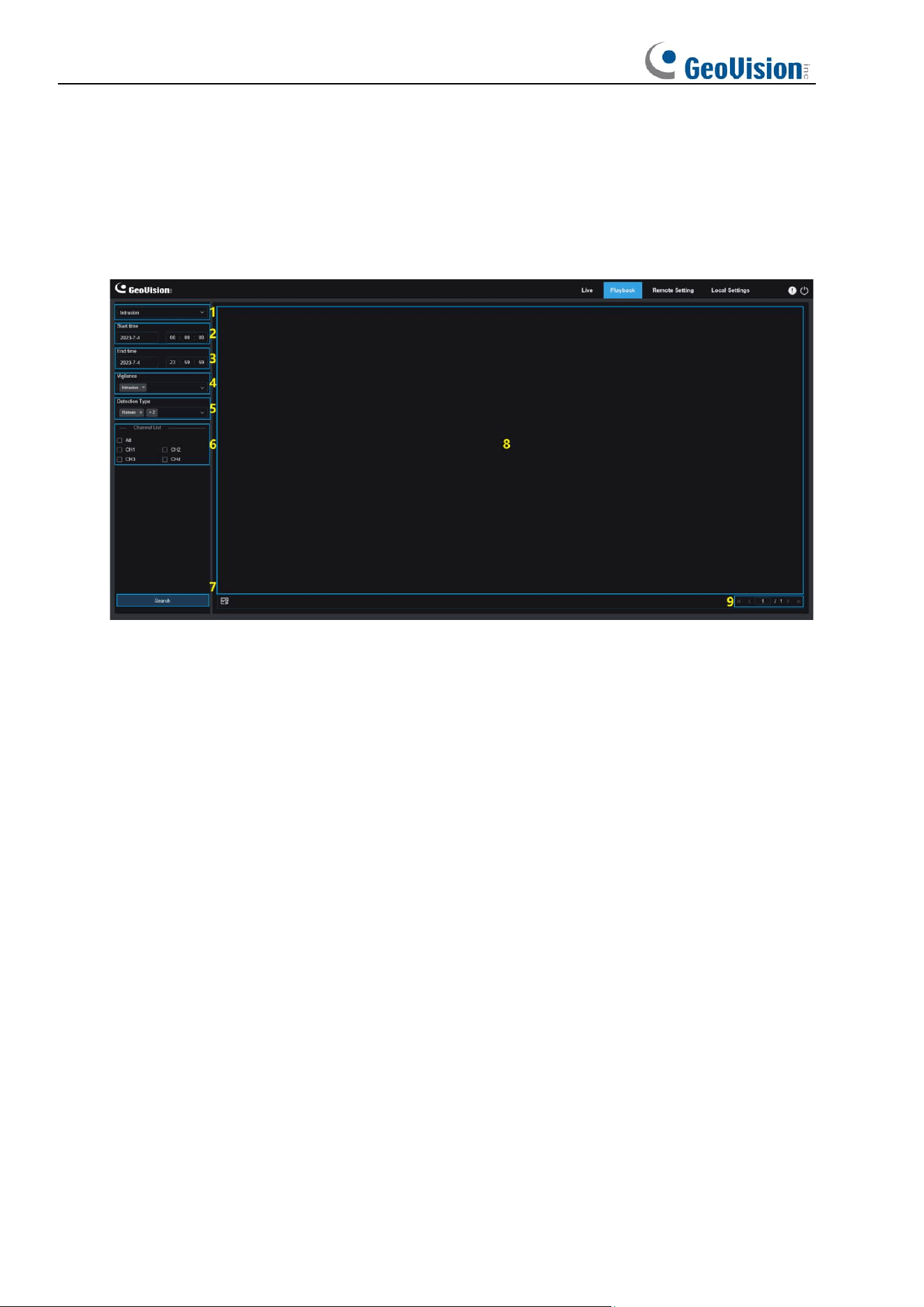
7.5.5 Region Entrance / Exiting
The region entrance / exiting detection function detects whether objects enter / leaves the set
warning area and triggers a linkage alarm according to the judgment. The pedestrian and
vehicle detection function is available to alarm pedestrian or vehicle objects and record image
or video information for easy retrieval and viewing. The following figure shows the screen.
1. Search Mode Switch: Enables users to switch search modes. The currently effective
search mode is Intrusion.
2. Start Time: Used to set the time to start searching for pedestrian & vehicle images.
3. End Time: Used to set the time to end searching for pedestrian & vehicle images.
4. Vigilance: Set the capture mode triggering an alarm to Intrusion.
5. Detection Type: Used to set pedestrian and/or vehicle images to search for as needed.
6. Channel Selection: Enables users to select channels to search for (only applicable to
G-RMS32810).
7. Search: Used to search for pedestrian & vehicle images according to search settings.
8. Search Result Display Area: Displays search results. When users double click an
image, the videos recorded just before and after the time period when the image is
captured will be played.
9. Search Result Scrolling Through: Users can turn search result pages in the lower right
corner.
56
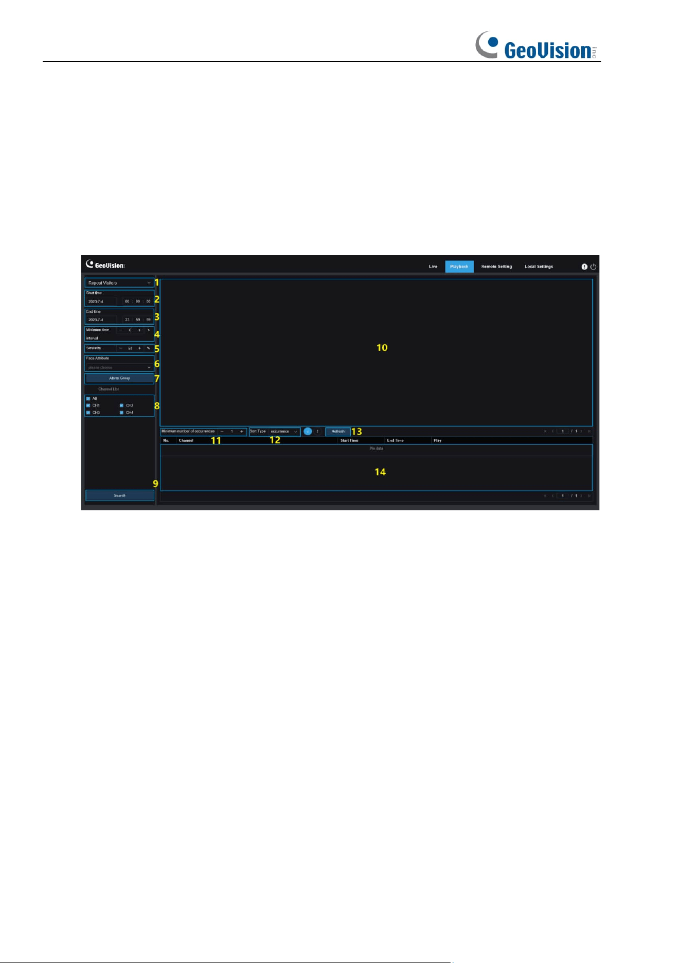
7.5.6 Repeat Visitor
The face recognition function can not only provide alarms in real time, but also deeply dig into
data to meet customer needs. For example, for the repeat customer detection function, a
camera is installed in a certain area of the mall. The repeat customer detection function allows
you to check whether a customer stops to check out goods in this area. You can also monitor
an area to check if a suspected target is frequently seen in that area. The repeat customer
function screen is shown in the figure below.
1. Search Mode switching: Used to switch the current search function. The current
Search Mode is AI-Repeat Visitor.
2. Start time: Used to set the start time to search for human and vehicle images.
3. End time: Used to set the end time to search for human and vehicle images.
4. Minimum time interval: Used to set the minimum time interval of capturing the same
object twice to increase the search accuracy.
5. Similarity: Used to set the lowest similarity between other images and the reference
image while matching repeat customers.
Note: This setting takes effect only when Alarm Group is unchecked for the current function.
6. Face Attribute: Used to filter searched images according to face feature values.
Note: The search will be applied on all images when this option is not set. When this option is
set, only captured images with Face Attribute enabled are searched.
7. Alarm Group: Used to identify repeat customers according to group settings in the
database.
Note: All images will be searched when no group limitations are set. In this case, the similarity
setting takes effect. Stranger information will be ignored when group limitations are set.

57
8. Channel Selection: Enables users to select channels to search for (only applicable to
GV-RMS32810).
9. Search: Used to search for the information of captured images according to settings.
10. Search Result Display Area: Displays the search results in a stacked manner.
Double-click on the displayed image information will list the stacked images on the
bottom, and click on the corresponding image again will jump to its quick replay.
11. Minimum number of occurrences: Used to filter search results by number of
occurrences. You have to click Refresh to update the display.
12. Sort Type: Used to sort search results chronologically or by capture count in ascending
or descending sequence. You have to click Refresh to update the display.
13. Refresh: Refresh the sorting in your IE according to Minimum number of occurrences
and Sort Type.
14. Secondary Search Result Display Area: Displays captured images of selected objects
in the form of event list according to the information selected in the search result display
area. You can click the Play button to go to quick replay.
58
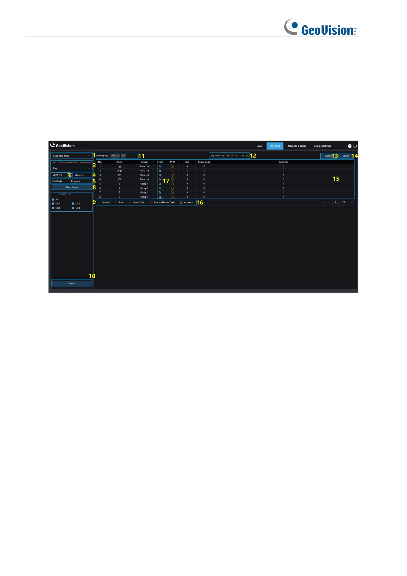
7.5.7 Face Attendance
In addition to the Repeat Visitor function, the face recognition function also provides the face
attendance function. The face attendance (FA) function is used to retrieve face matching
status in different groups (excluding stranger group) saved in the memory card in a specified
period of time, and generate attendance results according to capture records. The functional
screen is shown in the figure below.
1. Search Mode switching: Used to switch the current search function. The current
Search Mode is AI-Face Attendance.
2. Select Time Mode: Options include day, week, month, customize, and today. After you
select a type, the system will automatically change the start date and end date. If day is
selected, the end date and start date will be automatically synchronized. If week is
selected, the start date and end date will be automatically changed to Monday and
Sunday of the week to which the selected date belongs. If month is selected, the start
date and end date will be automatically changed to the first and last day of the month to
which the selected date belongs. If customize is selected, the search date is
customizable. If today is selected, the start date and end date will be changed to the
current date.
3. Start Date: Used to set the start date for searching by face attendance.
4. End Date: Used to set the end date for searching by face attendance.
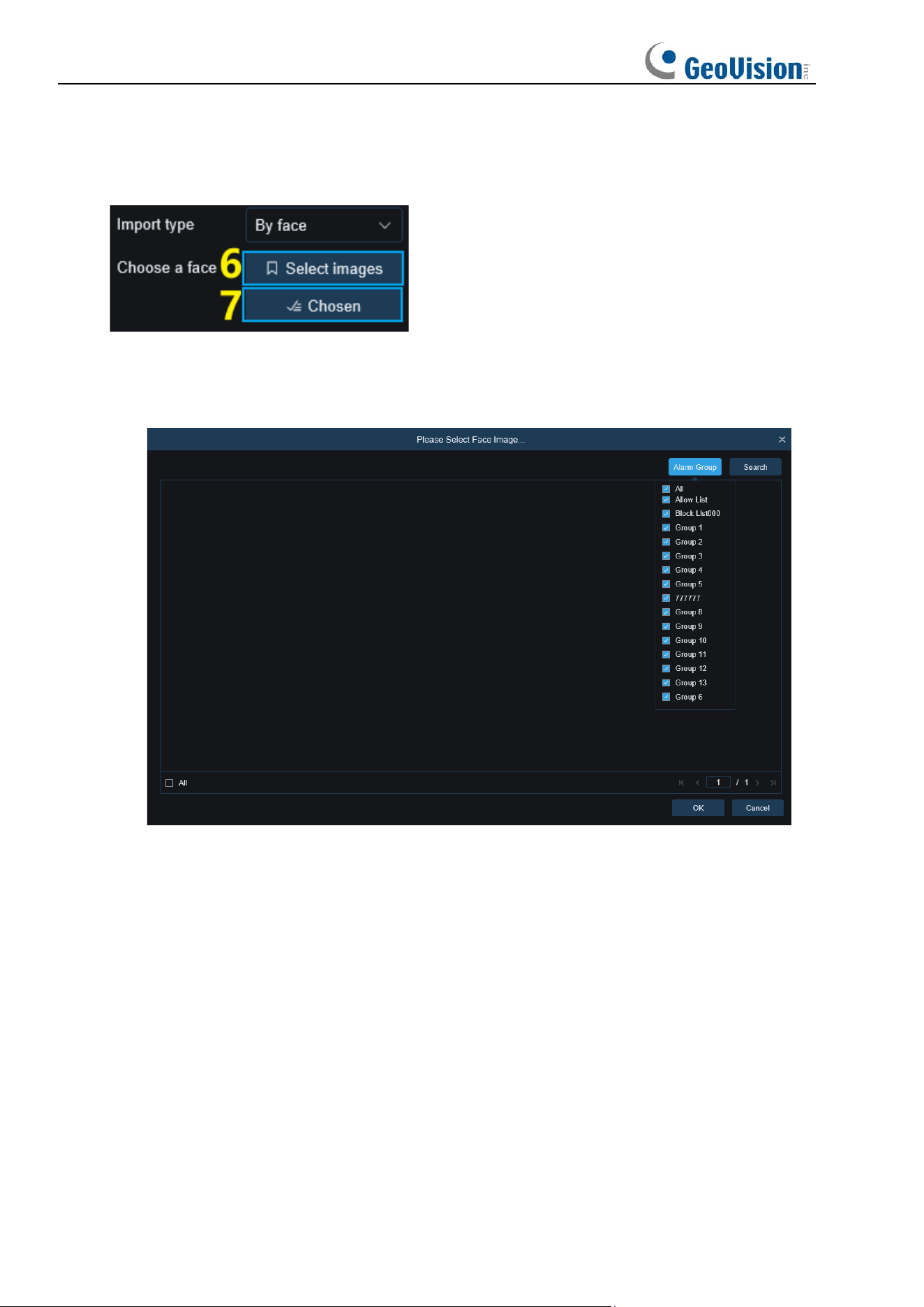
5. Import type: Used to select import type, including by group and by face. The former
takes all the people in the existing group as detection objects to search for matching
results. The latter selects people in a certain group to search for matching results.
When By group is selected, face attendance results will be searched according to groups set
in the database.
59
When By face is selected, the menu on the screen will change to that shown in the preceding
figure.
6. Select Image: Click to select face images to be detected. The window shown in the
following figure appears when you click this option.
Click Alarm Group to select a group and then click Search. All face images in this group will
be searched. Select the face images to be subject to face attendance, and click OK. Selected
face images will be added to the Chosen queue. You can click Cancel to close the window.
7. Chosen: Displays the queue of selected face images. The window shown in the
following figure appears when you click this option.
Select a face image and click Delete. You can delete the face image from the queue. You can
click All to select all face images. You can click Cancel to close the window.
8. Alarm Group: When by group is selected, face attendance results will be searched by
groups in the database.
9. Channel Selection: Enables users to select channels to search for (only applicable to
GV-RMS32810).
60
10. Search: Used to search face attendance information according to settings.
11. Working Day: You can set working day here.
12. Duty Time: You can set duty time here.
13. Refresh: After changing attendance parameters, you can click Refresh to refresh search
results.
14. Export: You can click Export to export results to your PC.
15. Search Result Display Area: Displays search results in a table at the upper right, as
shown in the figure below.
16. Secondary Search Result Display Area: Clicking on a person will display detailed time
information at the lower right. The timepoint that matches this person will be marked with
a red bar. Click on the red bar will jump to the corresponding quick replay.
Attendance Results: "←" indicates leave early, "→" indicates late, both indicates late and
leave early, "√" indicates normal attendance, and "○" indicates absence. The green lines
indicate the start and end time of attendance.
61
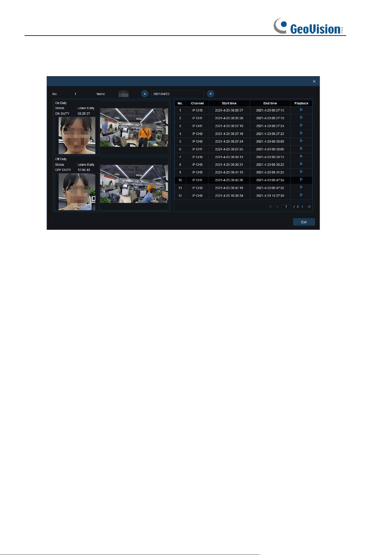
17. You can click the Detail icon to check details. You can click the playback icon to go to
quick replay.
You can click the arrow at the lower right corner on the result page to scroll through results.
62
8 Remote Setting
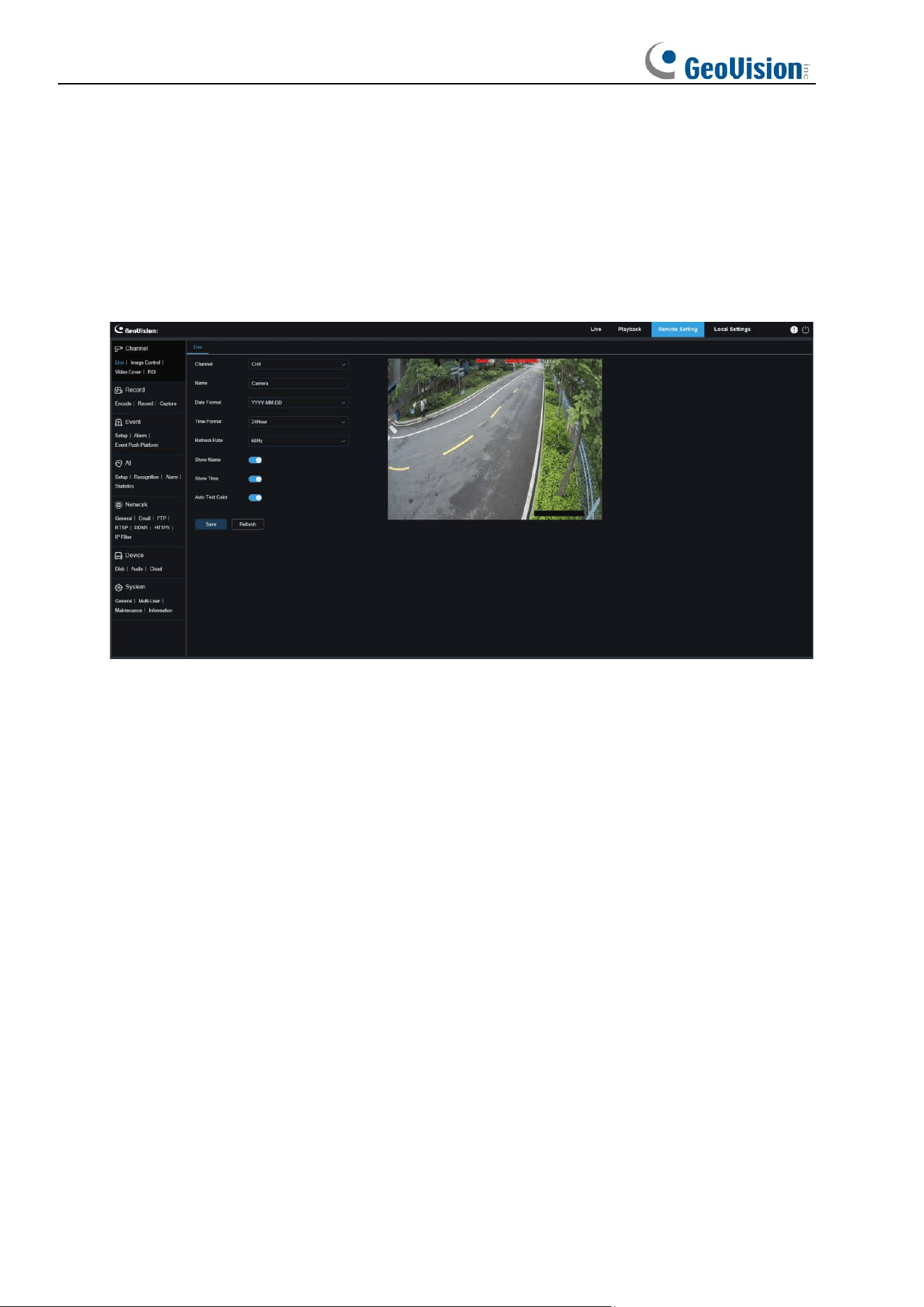
8.1 Live View
On the Live view, you can set channel name, device time, CC, as well as statistical data and
image covering. The view is shown in the figure below.
Channel: Users can select a channel and set parameters (only applicable to GV-RMS32810).
Name: Here, you can set the channel name of the camera displayed on the OSD.
Date Format: Here, you can set the date format of the camera displayed on the OSD,
including MM/DD/YYYY, YYYY-MM-DD, and DD/MM/YYYY.
Time Format: Here, you can set the hour format of the camera on the OSD, including
12-Hour and 24-Hour.
Refresh Rate: Here, you can set the image refresh rate, including 60 Hz and 50 Hz,
corresponding to N and P respectively.
Show Name: Here, you can set whether to display channel name on images.
Show Time: Here, you can set where to display channel time on images.
Auto Text Color: The OSD font color of the camera time and channel name is self-adaptive.
The color switches between white and black based on the image background to ensure clear
display.
Channel Name Display Location: Here, you can set the location where the channel name
appears by dragging its location on the image.
Time Display Location: Here, you can set the location where the channel time appears by
dragging its location on the image.
63
Alarm Statistic Display Location: Here, you can set the location where alarm statistic
appears by dragging its location on the image. This setting is available only when the alarm
statistic display function is enabled.
Save: Used to save current changes.
Refresh: Used to refresh parameters on the current view.
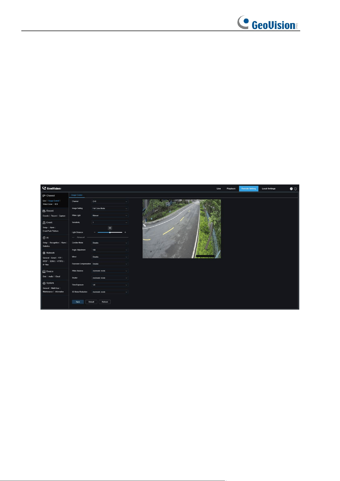
8.2 Image Control
Image control is to directly control and modify graphic parameters, such as color to black
mode, wide dynamic range, backlight compensation, etc. The view is shown in the figure
below.
Channel: Users can select a channel and set parameters (only applicable to GV-RMS32810).
Image Setting: Used to set a camera image mode. There are three modes in total (only
applicable to GV-RMS32810).
Full Color Mode: The camera works in Full Color Mode.
Day/Night Mode: The camera works in Day/Night Mode.
Scheduled: The camera works in Schedule Mode. Users can set the schedule to
automatically switch between Full Color Mode and Day/Night Mode.
White Light: Used to set the supplementary lighting effect of the warm light in Full Color
Mode. There are four modes in total (only applicable to GV-RMS32810).
Automatic Mode: In this mode, the camera automatically adjusts the intensity of the fill
light according to ambient illumination.
Manual: In this mode, the camera supplements the lighting effect at a fixed brightness
value.

64
Scheduled: In this mode, users can set the schedule to automatically supplement the
lighting effect by automatically turning on or off the warm light.
OFF: Used to turn off the warm light.
(White Light) Sensitivity: Specifies sensitivity 0-3, indicating the degree to which the camera
senses the ambient light. The higher the value is, the higher the sensitivity is.
(White) Light Distance: Specifies value range 0-100. White Light is the adjusted brightness
value of the fill light in Manual mode. The higher the value is, the higher the brightness is.
IR-CUT Mode: Used to set the day/night switching mode of the camera in Day/Night Mode.
There are five mode options.
Automatic mode: Used to automatically control the Switching mode. Among them, color
to b/w is judged by images and b/w to color is judged by light sensitivity to ambient light.
Color Mode/Day: Forced Color mode will not be switched to b/w.
Black White Mode/Night: Forced B/W mode will not be switched to color.
Image Mode: Similar to the Automatic Mode, color to black and black to color are judged
by images (for non-photosensitive models).
Scheduled: Used to switch between b/w and color as scheduled. If this function is
enabled, the start time and end time for night vision shall be set.
IR-CUT Delay: Used to switch day/night for the Automatic Mode and Image Mode. The
day/night switchover delay is adjustable from 1 s to 36 s. The day/night switchover is
performed only when the ambient illumination meets switchover requirements and the
retention time exceeds the preset threshold.
IR-CUT Sensitivity: Sensitivity 0-3. The degree to which the camera is sensitive to ambient
light. The higher the value is, the higher the sensitivity is.
IR-LED: Used to set the fill-in light effect of the IR light at night vision. There are three mode
options.
Smart IR: Used to intelligently control the fill-in light intensity of the IR light according to
focal length and overexposure condition.
Manual: Manual Mode in which the fill-in light is applied in the form of the set brightness
of the IR light.
OFF: No light complement is available.
Low Beam Light: Here, you can manually adjust the brightness of the IR light (0 to100, of
which 0 indicates that the IR light is off and 100 indicates the highest brightness).
Corridor Mode: Corridor Mode.
Angle Adjustment: Image rotation setting. The camera is reverse to the presetting in some
usage scenarios. For example, the camera is designed to be hung upside down, but in
practice it is used flatwise. You can set this value to adjust the image.
Mirror: You can set the mirror mode to adjust the picture effect. There are four mode options.
Disable: Used to disable the Mirror Mode.

65
Vertical: Used to set the Mirror Mode in the vertical direction to interact the image on the
picture up and down.
Horizontal: Used to set the Mirror Mode in the horizontal direction to interact the image
on the picture left and right.
All: Used to enable Vertical and Horizontal at the same time. The effect is similar to that
of 180° rotation, but the implementation principle is different.
Exposure Compensation: Used to set the performance of the program when the backlight is
turned on. There are four mode options.
WDR: Wide dynamic range in which the picture is uniformly balanced based on the
setting and both light and dark areas can be clearly distinguished.
HLC: Highlight compensation in which the objects in the highlighted area are clearer in
the picture. (applicable for some models).
Back Light: Backlight compensation in which the objects in the dark area are clearer.
Disable: An image will not be optimized with backlight on.
White Balance: White balance is a measure of the accuracy of white produced by mixing red,
green, and blue. There are two mode options.
Automatic mode: Allows you to adjust the white light using default parameters.
Manual: Allows you to actively set the synthetic gained white light of red, green, and blue.
Shutter: Used to set the shutter exposure time. There are two mode options.
Automatic mode: The program automatically selects a proper exposure time according to
the Time Exposure setting.
Manual: Allows you to directly use the Time Exposure setting.
Note: Deselect the flickerless option of the exposure time in shutter manual mode, and select
the option in shutter auto mode. If you switch the shutter to manual mode, the exposure time
is switched automatically to 1/100 or 1/120.
Time Exposure: Used to set the exposure time of the camera and use this parameter in
combination with Shutter. When the exposure time is too long, there may be overexposure.
When the exposure time is too short, the picture may be dark.
3D Noise Reduction: You can reduce image noise by setting this parameter to obtain a
clearer picture. There are three mode options.
Automatic mode: In this mode, the camera will automatically select the noise reduction
effect according to algorithms.
OFF: Used to disable the noise reduction function.
Manual: Allows you to manually set the noise reduction coefficient to reduce image
noise.
Save: Used to save parameter changes to an image.
Default: Used to restore image parameters to default settings.
Refresh: Used to refresh image parameters.
66
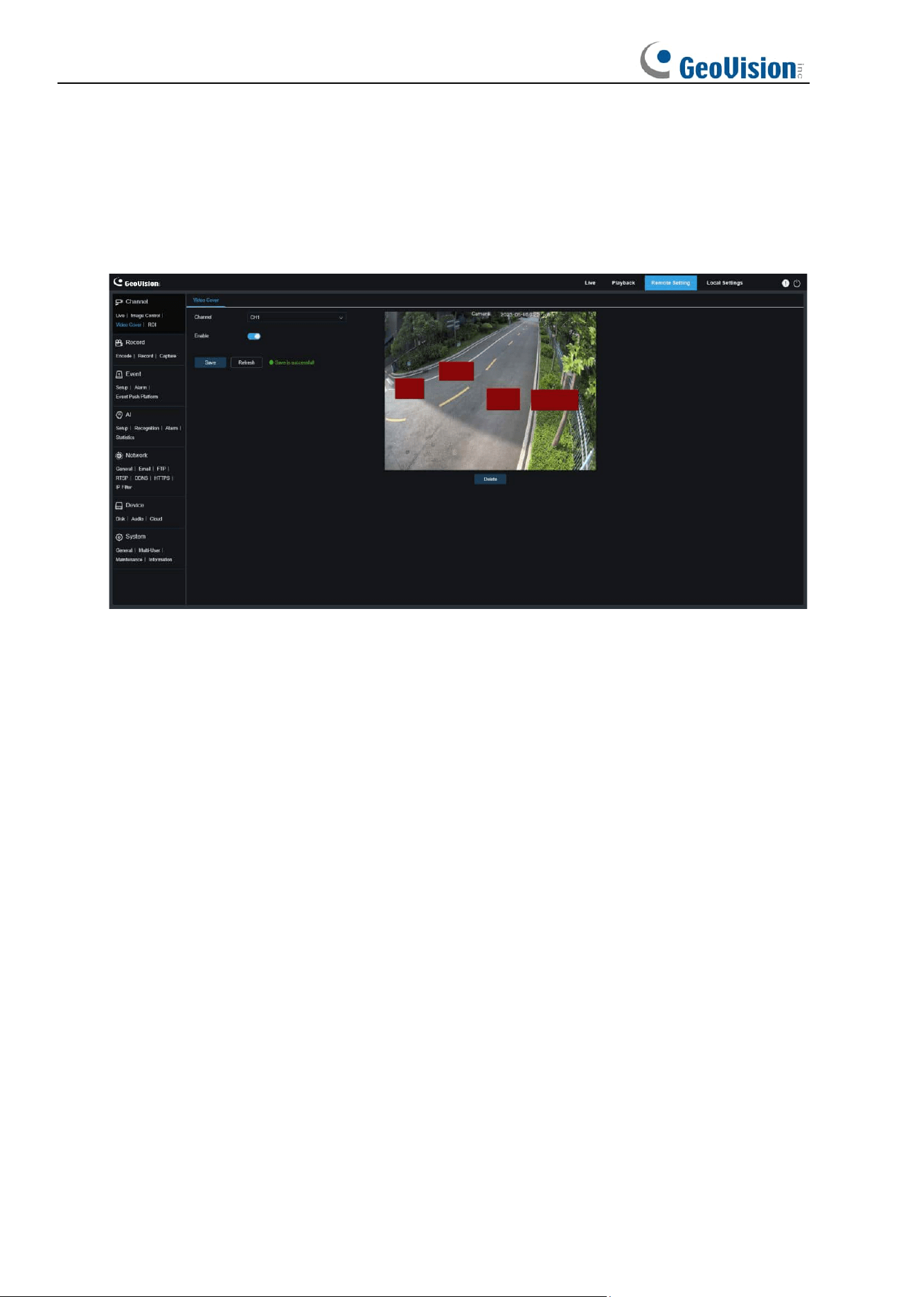
8.3 Video Cover
In practical applications, if areas that can be monitored by the camera are not suitable for
monitoring and recording, you can use this function to occlude these areas. The screen is
shown in the figure below.
Channel: Users can select a channel and set parameters (only applicable to GV-RMS32810).
Enable: Used to enable the video tampering function.
Tampering Area Setting: Used to set the areas to be tampered in the monitoring screen. The
tampered blocks are red while setting and will turn to black after they take effect. You can set
four tampering blocks.
Delete: Used to delete selected tampering blocks.
67
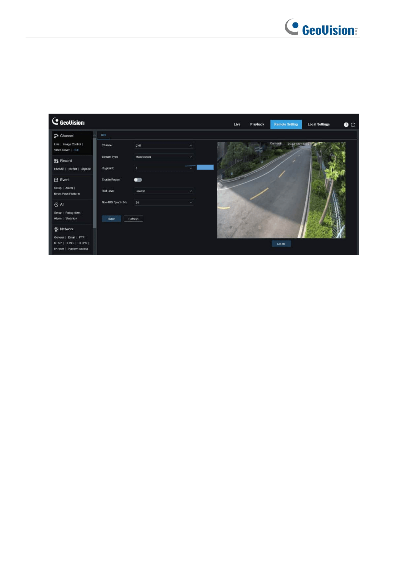
8.4 ROI
ROI (sensitive area) is a region of interest selected from the video area. This area can be set
to a different frame rate and sharpness than the unselected area.
Channel: Users can select a channel and set parameters (only applicable to GV-RMS32810).
Stream Type: Used to select the stream type you want to set.
Bitrate: Used to select the bit rate to be set.
Region ID: Used to select region IDs. You can set up to eight regions.
Enable Region: Used to enable regions.
ROI Level: Used to set image quality in regions. The higher the quality, the higher the
resolution and frame rate.
Non-ROI Fps: Used to set the frame rate of non-region of interest.
Note: ROI is supported in some models.
68
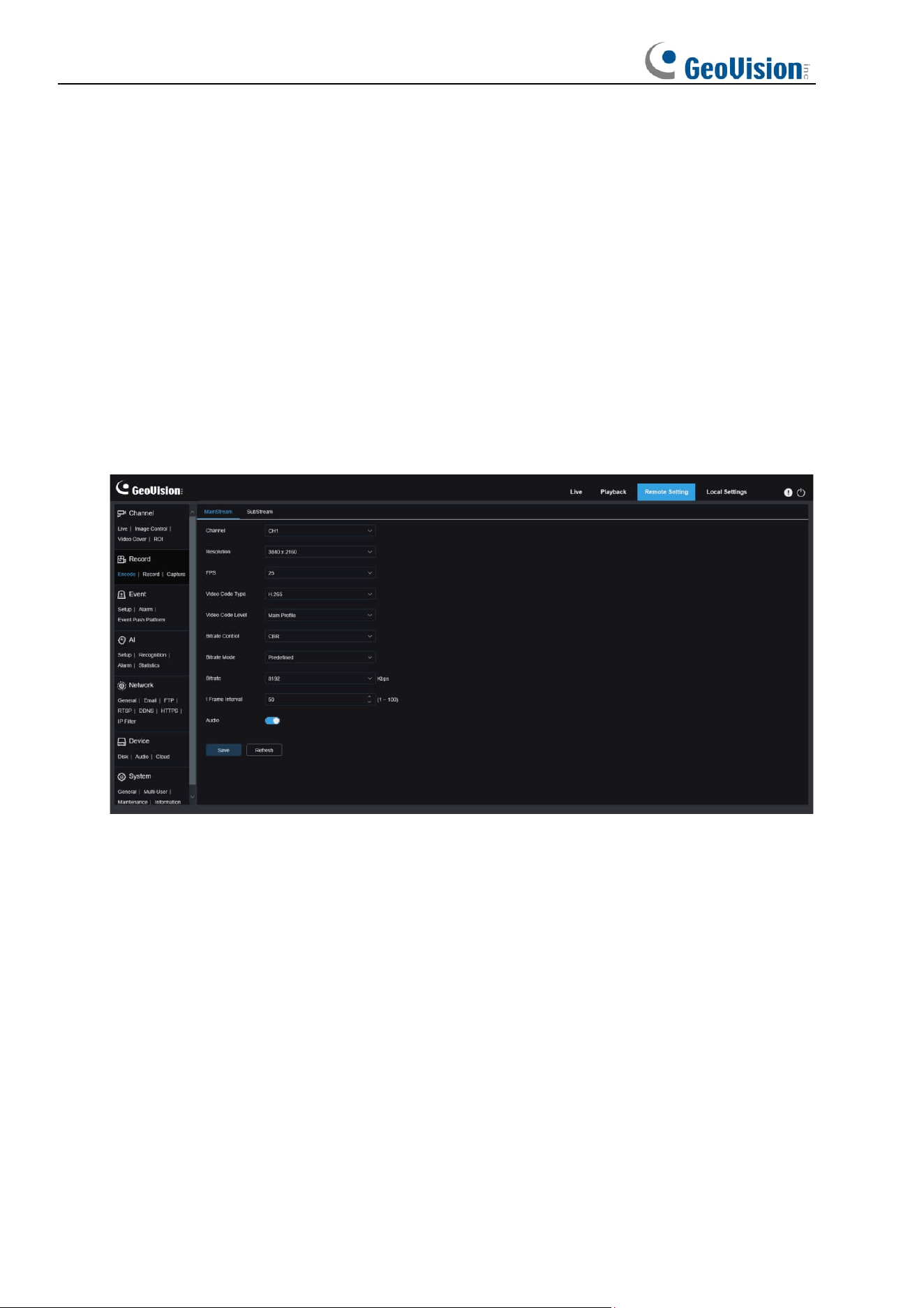
8.5 Recording Parameters
This menu allows you to configure preview parameters and recording parameters.
8.5.1 Encoding Parameters
This menu allows you to configure the image quality for video recording or network
transmission. In general, "MainStream" defines the quality parameters of recorded videos that
will be stored in the HDD, "SubStream" defines the quality parameters of live videos that are
remotely accessed from for example the web client and CMS, and "MobileStream" (can be
turned off) defines the quality parameters of live views that are remotely accessed and viewed
from mobile devices.
Channel: Users can select a channel and set parameters (only applicable to GV-RMS32810).
Resolution
: This parameter defines the resolution of a recording image.
FPS
: This parameter defines the frame rate of recording in your IPC.
Video Code Type:
Channel decoding types. The options include H.264, H.265.
Video Code Level:
Video quality levels. The options include Baseline, Main Profile, and High
Profile (for H.265, only Main Profile is available).
Bitrate Control
: Used to select a bit rate level. For a simple scenario such as a plastered wall,
a constant bit rate is preferred. For a complicated scenario such as a busy street, a variable
bit rate is preferred.
Bitrate Mode:
To manually set a bit rate, select the "User-defined" Mode. To select a preset
bit rate, select the "Predefined" Mode.
Bitrate:
This parameter corresponds to the data transmission speed used by the IPC to
record a video. Recording in a higher bit rate will gain better image quality.
I Frame Interval
: Used to set an I-frame interval. This option is only available in the IPC.
69
Audio:
Select this option if you want to record both audio and video and connect your
microphone to IPC or use a camera with audio capability.
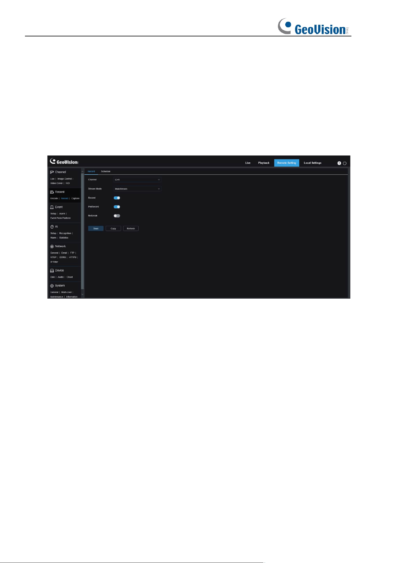
8.5.2 Recording Parameters
8.5.2.1 Recording Parameters
This menu allows you to set recording parameters.
Channel: Users can select a channel and set parameters (only applicable to GV-RMS32810).
Stream Mode
: Used to select a Recording Mode, that is, video stream to be saved in the
memory card. The main stream is selected by default.
Record
: Select this option to start recording.
PreRecord
: If this option is enabled, the IPC will start recording a few seconds before an
alarm event occurs. This option is recommended if your main recording type is based on
motion detection or I/O alarm.
Netbreak: If this option is selected, recording continues even when the network is
disconnected or network failure occurs.
Copy: Users can copy the parameters of the current channel to other channels.
70
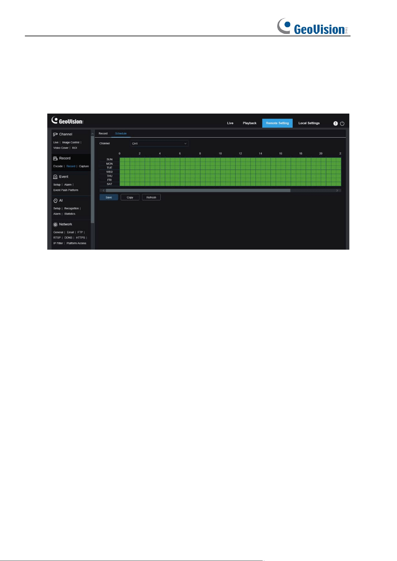
8.5.2.2 Recording Plan
This menu allows you to specify when the IPC starting recording. You can set a recording plan
in the recording schedule. The recording is performed only within the selected time period.
You can drag your cursor to mark areas.
71
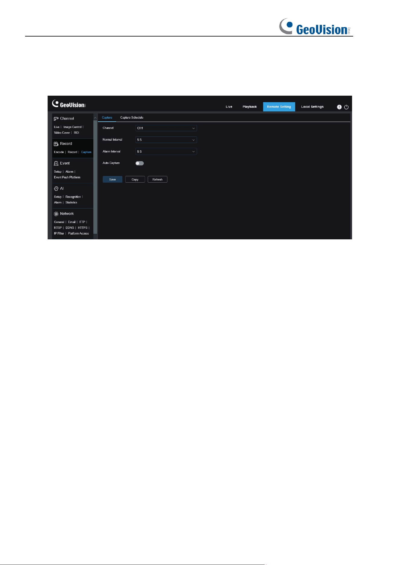
8.5.3 Capture
8.5.3.1 Capture Settings
Channel: Users can select a channel and set parameters (only applicable to GV-RMS32810).
Normal Interval
: Normal capture interval, used to specify the capture interval in normal
recording.
Alarm Interval
: Alarm capture interval, used to specify the capture interval when motion
detection, or I/O alarm is triggered.
Auto Capture
: Automatic capture.
72
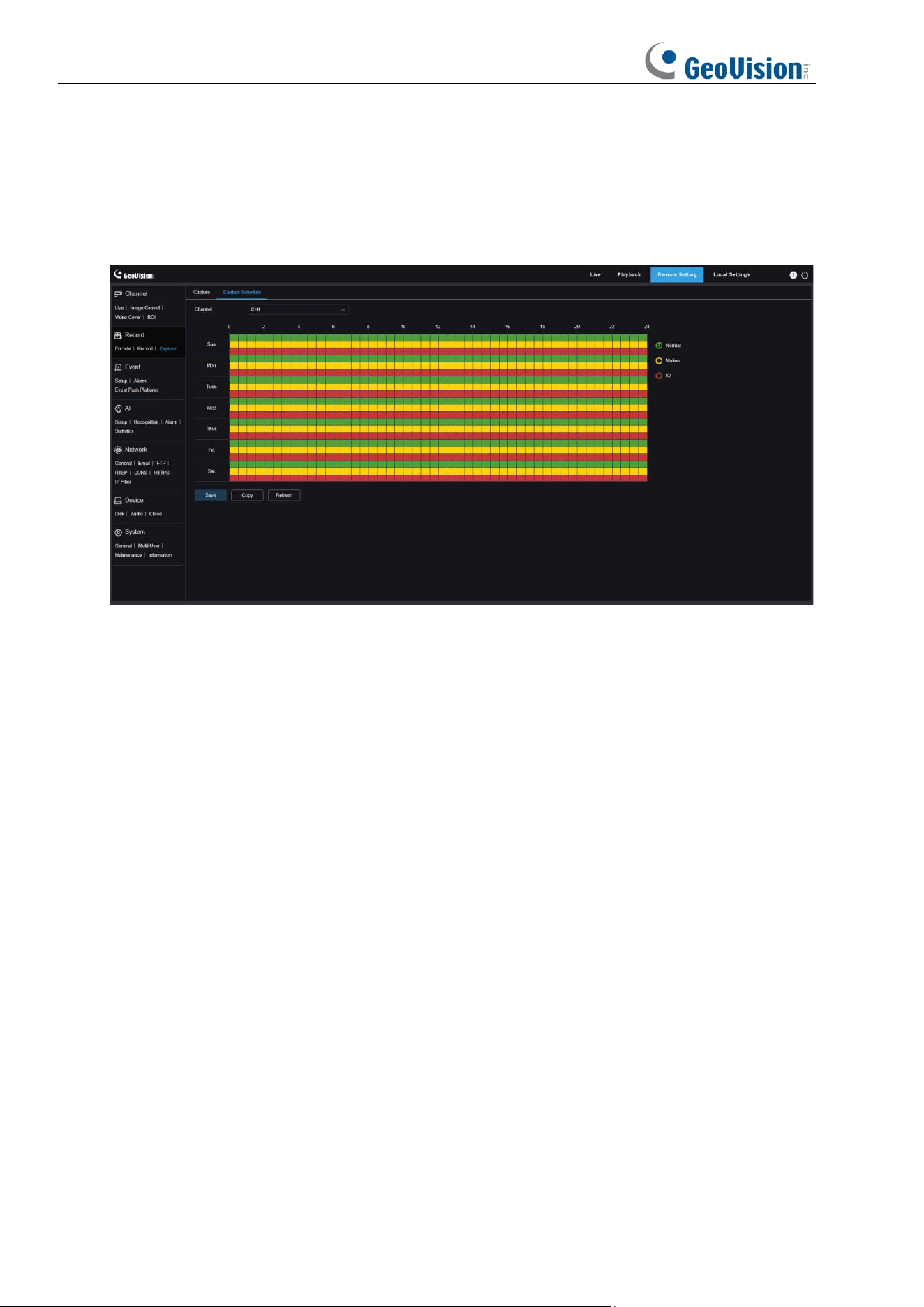
8.5.3.2 Capture Schedule
This menu allows you to specify when the IPC capture images. You can set a capture plan in
the capture schedule. The capture is performed only within the selected time period. You can
drag your cursor to mark areas.
Channel: Users can select a channel and set parameters (only applicable to GV-RMS32810).
Normal
: When the area is marked green, the channel performs normal capture on the area in
the corresponding time period.
Motion
: When the area is marked yellow, the channel performs motion capture on the area in
the corresponding time period.
IO
: When the area is marked red, the channel performs I/O alarm capture on the area in the
corresponding time period.
No Capture
: When the area is marked black, the channel will not perform capture in this time
period.
73
8.6 Event Setup
8.6.1 Parameter Setup
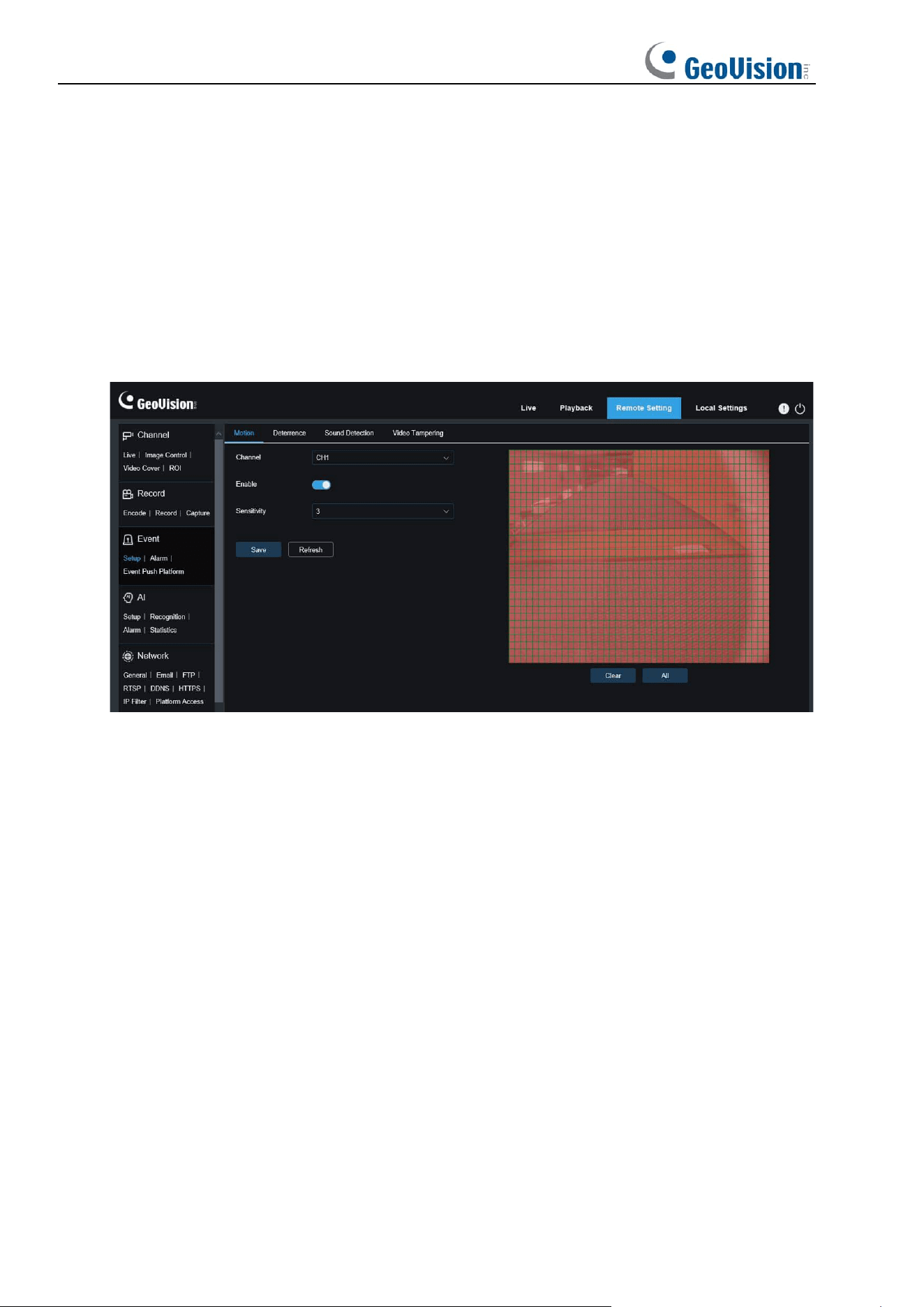
8.6.1.1 Motion Detection
This menu allows you to configure motion detection parameters. When motion is detected, a
series of alarms will be triggered, such as sending an email alert with attached images from
the camera (if this option is enabled) and a push notification via the app.
You can drag the left mouse button to delimit the detection area in the right window. An alarm
will be triggered only when motion is detected in this area.
Channel: Users can select a channel and set parameters (only applicable to GV-RMS32810).
Enable: Used to enable or disable motion detection.
Sensitivity: Used to set the sensitivity of motion detection. The higher the value, the higher
the sensitivity.
SMD by Camera:
Intelligent motion detection. You can set the target detection type and area.
The motion detected in the area can trigger an alarm. The detection type includes the
following four options: Motion, Pedestrian, Vehicle, and Pedestrian
&
Vehicle. (Note: Only
some models support target detection.)
74
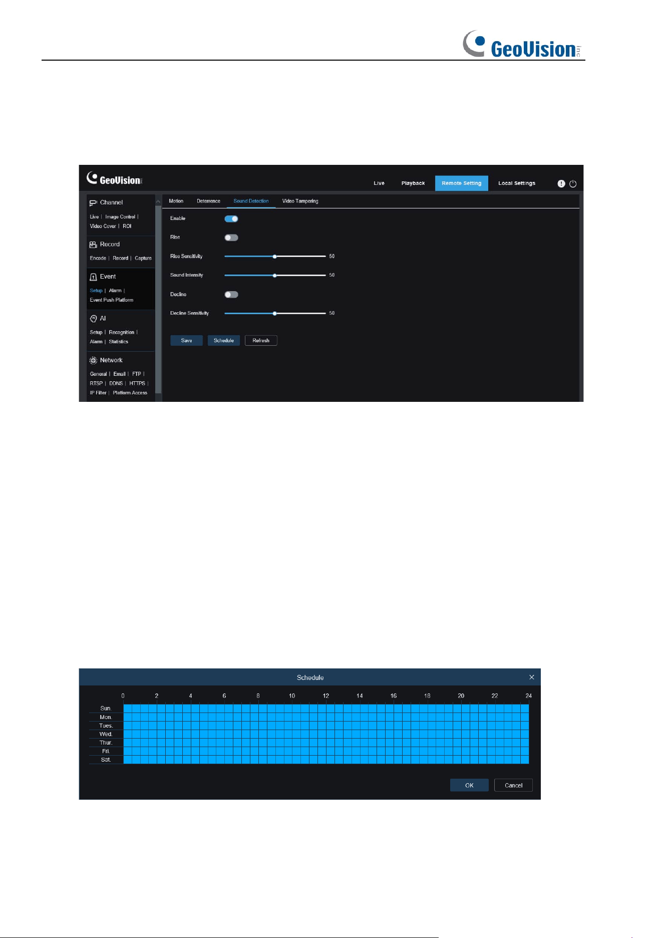
8.6.1.2 Sound Alarm
Used to set the response to sound alarm. An alarm will be triggered when the camera detects
that the connected audio has changed and the requirement of alarm detection is met.
Channel: Users can select a channel and set parameters (only applicable to GV-RMS32810).
Enable: Used to enable or disable audio detection.
Rise: Volume rise switch. When this option is turned on, an alarm will be triggered only when
the volume rises steeply.
Rise Sensitivity: Rise sensitivity. The higher the value, the easier it is to trigger an alarm.
Sound Intensity: Used to send sound intensity. This setting is the sound threshold. The
larger the threshold, the louder the sound is required to trigger a rise alarm, and vice versa.
Decline: Volume decline switch. When this option is turned on, an alarm will be triggered only
when the volume declines steeply.
Decline Sensitivity: Decline sensitivity. The higher the value, the easier it is to trigger an
alarm.
Schedule: Used to set a sound alarm schedule. A sound alarm will be triggered only within
the planned time.
75
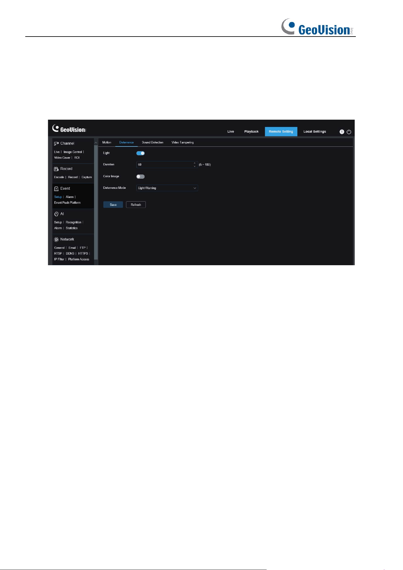
8.6.1.3 White Light Deterrence
When the camera supports white light, users can configure deterrence parameters in this
menu. When a deterrence alarm is triggered, the white light will be automatically turned on for
deterrence purpose. Note that this is only applicable to white-light supporting models. See the
following figure:
Note: When the camera supports white light and image control is set to Full Color Mode, the
white light parameters are grayed out and unavailable. All parameters on this page can be set
when image control is set to Day/Night Mode.
Light: Used to turn on or off a light alarm.
Duration: Specifies the duration for which the white light is turned on.
Color Image: Used to enable or disable Color Image. When this option is enabled, if the
Day/Night Mode is switched to the Night Vision mode, when an alarm is triggered and white
light deterrence is enabled, the image will switch to Color Mode and switch back to the Night
Vision mode until white light deterrence ends.
Deterrence Mode: Used to set the white light mode. There are two modes:
Light Warning: Steady-on mode, in which the white light is steadily on during deterrence.
Light Strobe: Blink mode, in which the white light blinks at a set frequency during
deterrence.
76
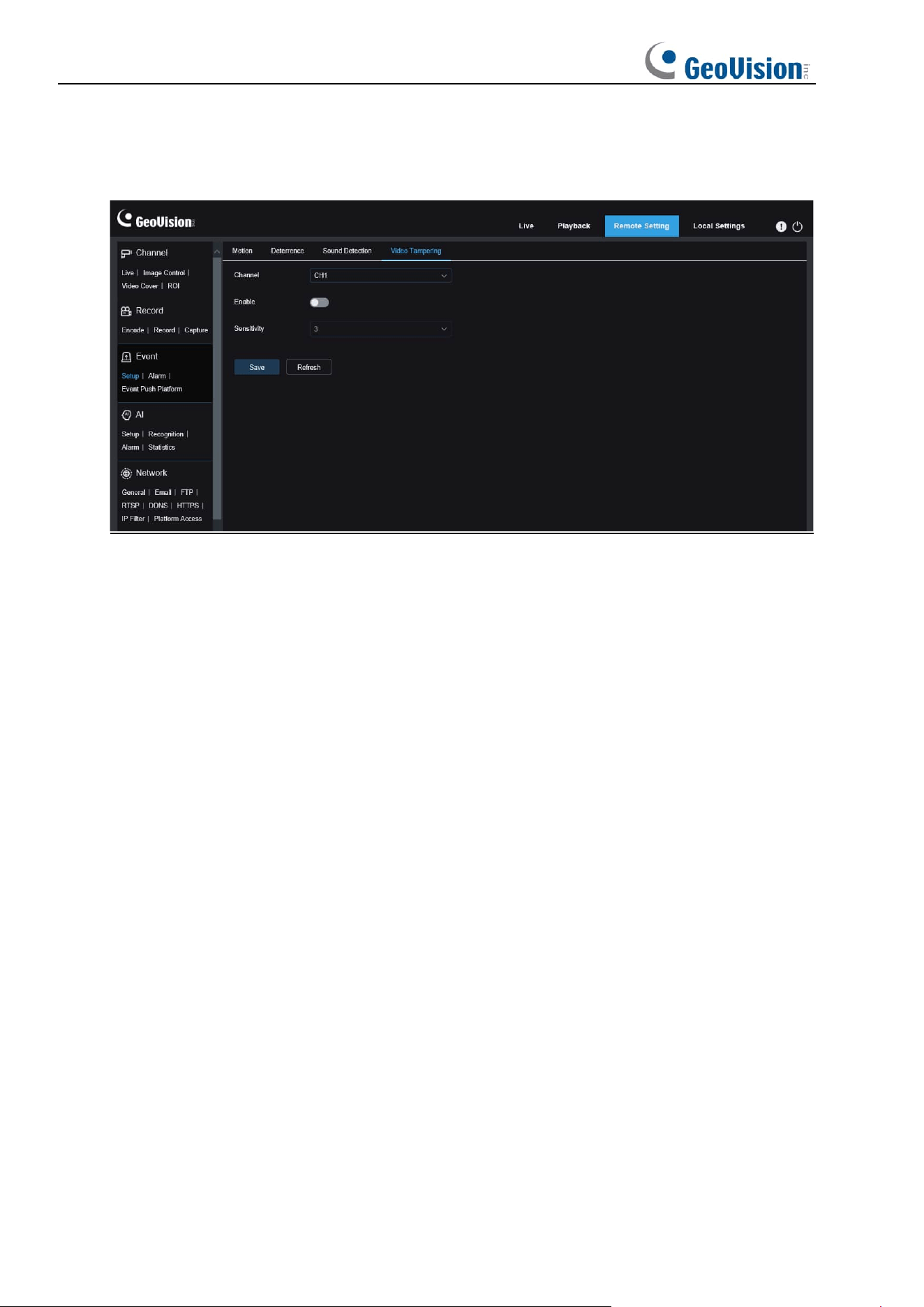
8.6.1.4 Video Tampering Detection
Used to detect the live view tampering and trigger an alarm.
Channel: Users can select a channel and set parameters (only applicable to GV-RMS32810).
Enable: Used to enable or disable video tampering detection.
77
8.6.2 Alarm Setting
This menu allows you to set the actions to be performed when an alarm is triggered.
8.6.2.1 Motion Detection
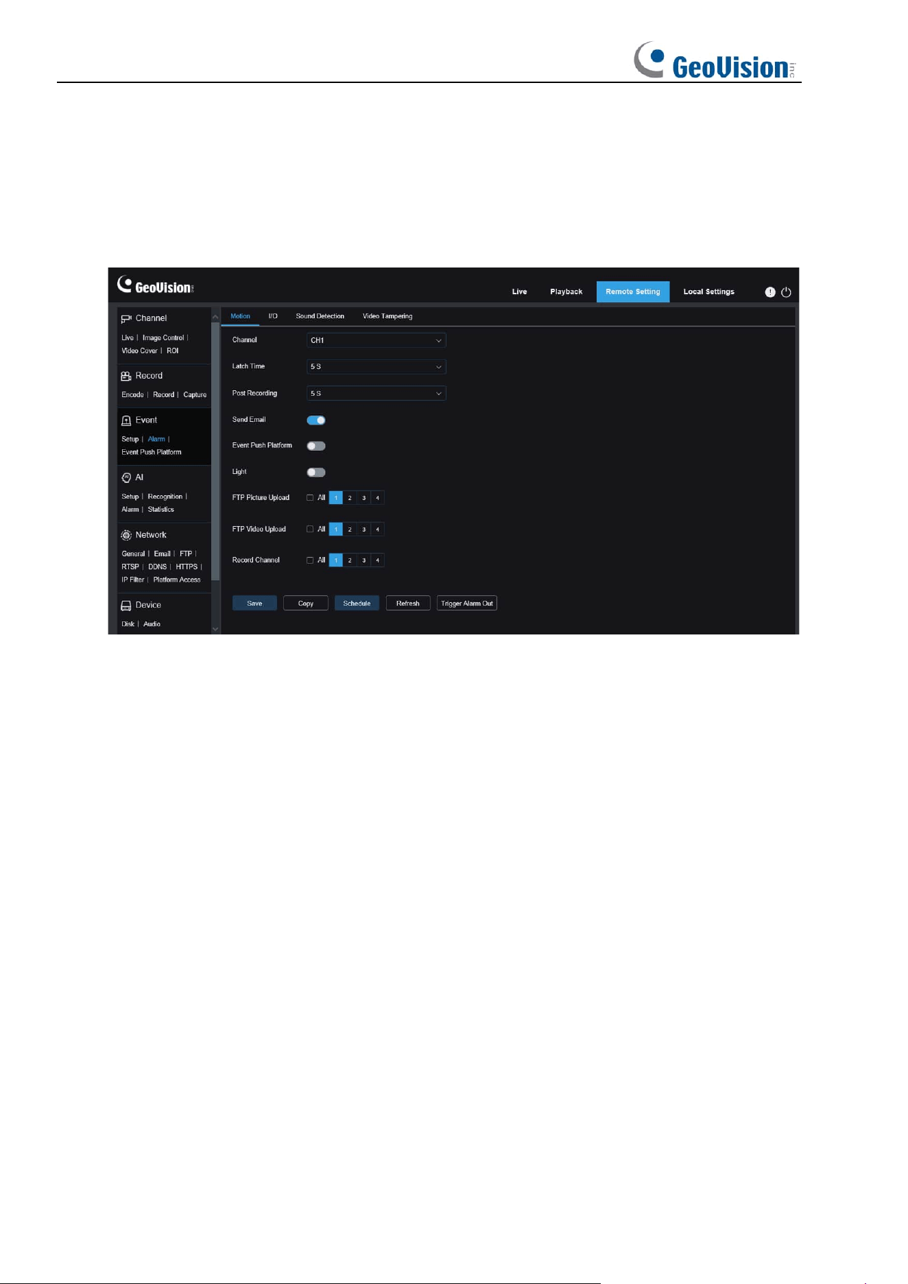
Channel: Users can select a channel and set parameters (only applicable to GV-RMS32810).
Latch Time
: Used to set the duration for triggering an external alarm when motion is
detected.
Post Recording
: You can set the duration of continuous recording after an event occurs. The
options include 5s, 10s, 20s, and 30s. The default duration is 5s, but the maximum duration
can be set to 30s.
Send Email:
You can have the device automatically send you an email when it detects
motion.
FTP Picture Upload: Used to upload alarm pictures to the FTP server. For GV-RMS32810,
you can select the desired channel(s) or all channels.
FTP Video Upload: Used to upload alarm videos to the FTP server. For GV-RMS32810, you
can select the desired channel(s) or all channels.
Alarm Out: Optional. If your device supports connection to an external alarm device, you can
turn on this switch to activate the external alarm device.
Enable Record: If this option is turned on, this kind of recording will be enabled when an
alarm is triggered.
Event Push Platform: If this option is set to ON, this type of information will be pushed to the
client when an alarm is triggered.
Light: When this option is enabled, the white light will be turned on for deterrence when an
alarm is triggered (only applicable to GV-RMS32810).
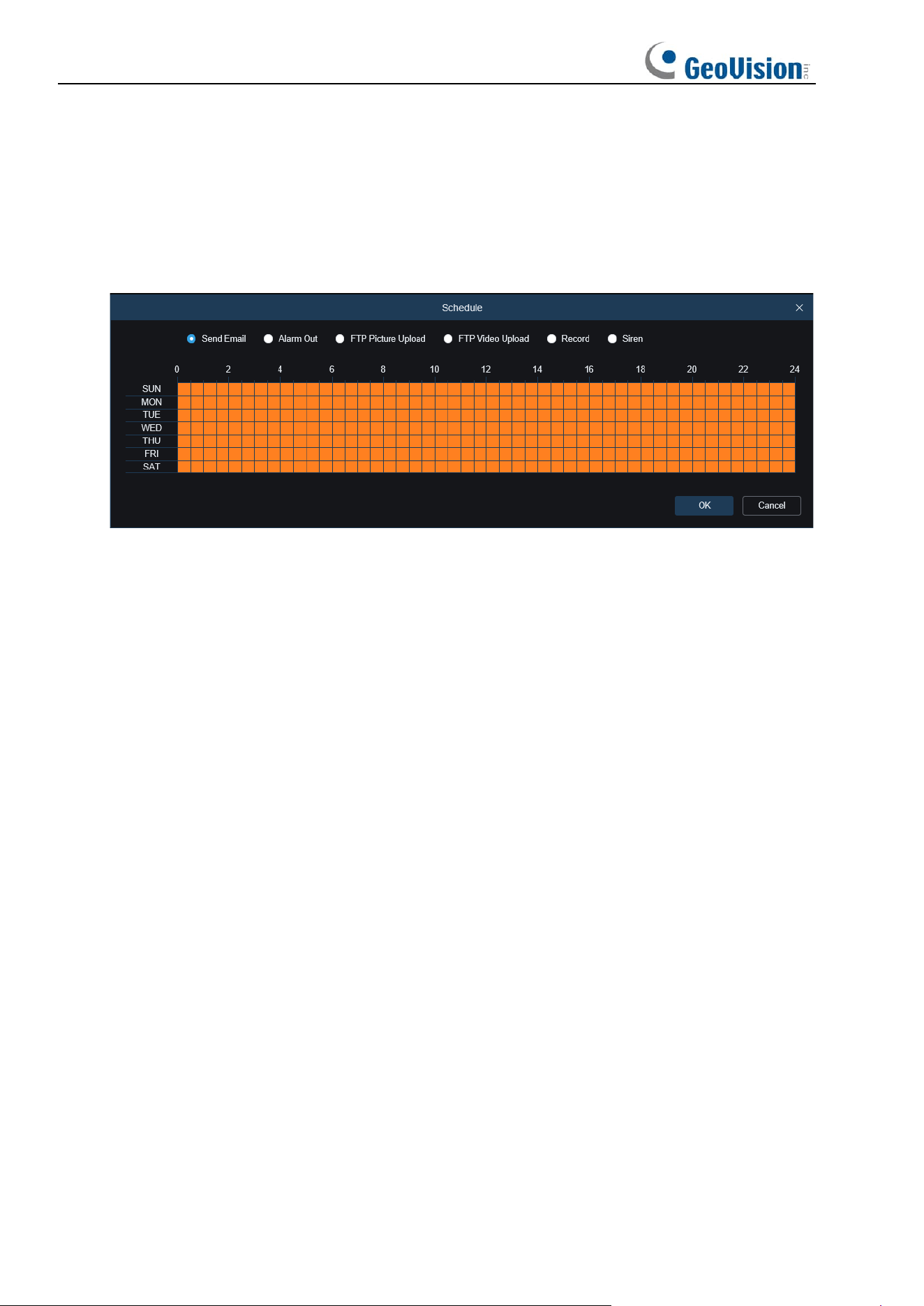
78
Record Channel: Recordings of this type will be recorded according to selected channels
when an alarm is triggered (only applicable to GV-RMS32810).
Copy: Users can copy the parameters of the current channel to other channels (only
applicable to GV-RMS32810).
Schedule: Used to set the scheduled time when an alarm acts. A series of alarm actions are
triggered only within the scheduled time.
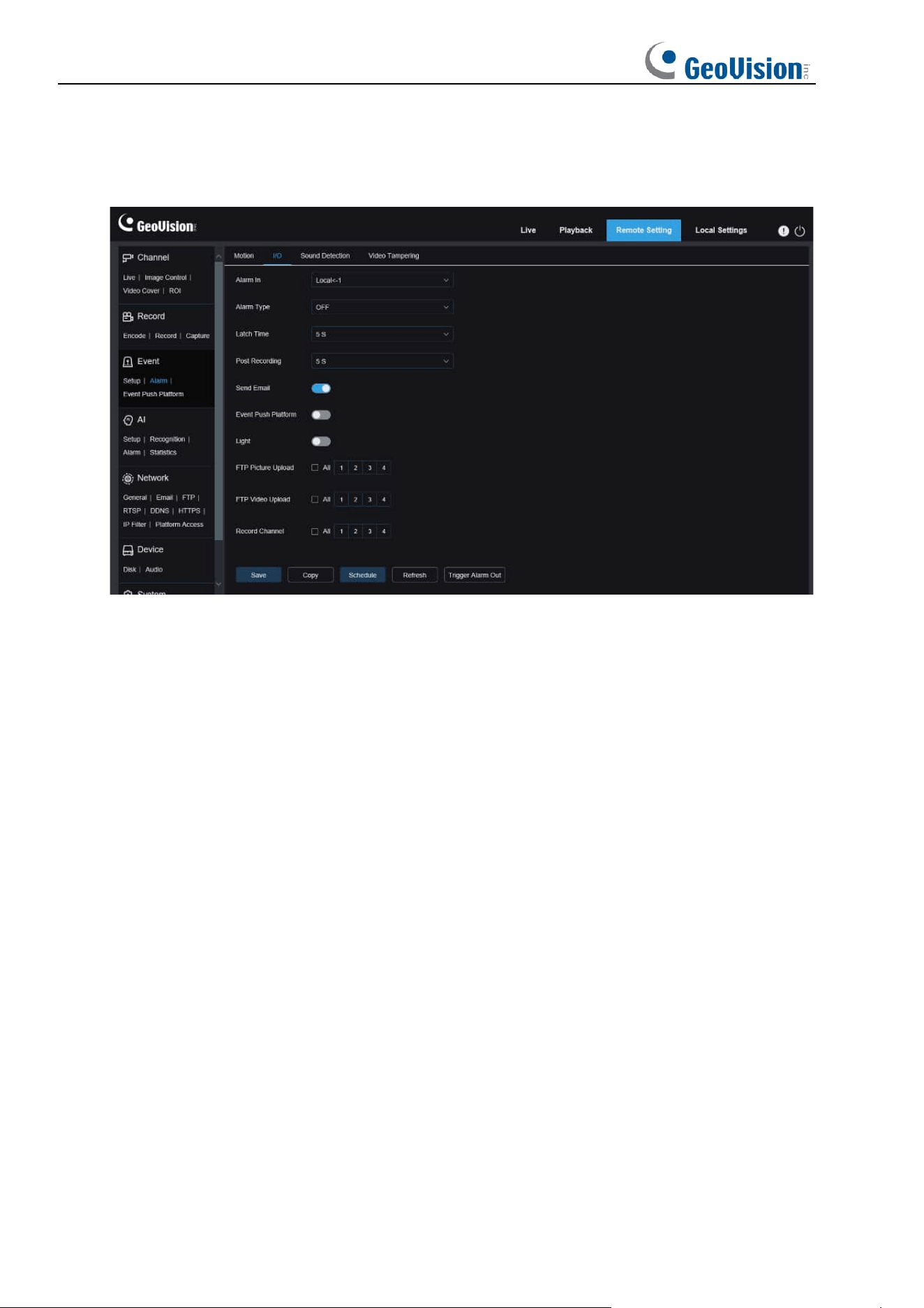
79
8.6.2.2 I/O Alarm
This function is available only when your device supports I/O sensors and is connected to an
external I/O alarm device.
Alarm In:
Users can select Local<-1 or Local<-2 to generate an alarm (only applicable to
GV-RMS32810).
Alarm Type:
You can select three alarm types: NO, NC, and Off. You can select a type that
matches your sensor type, or select "OFF" to turn off sensor triggering.
Latch Time
: Used to set the duration for triggering an external alarm when an I/O alarm is
triggered.
Post Recording
: You can set the duration of continuous recording after an event occurs. The
options include 5s, 10s, 20s, and 30s. The default duration is 5s, but the maximum duration
can be set to 30s.
Send Email:
You can have the device automatically send you an email when it detects an I/O
alarm.
FTP Picture Upload: Used to upload alarm pictures to the FTP server. For GV-RMS32810,
you can select the desired channel(s) or all channels.
FTP Video Upload: Used to upload alarm videos to the FTP server. For GV-RMS32810, you
can select the desired channel(s) or all channels.
Alarm Out: Optional. If your device supports connection to an external alarm device, you can
turn on this switch to activate the external alarm device.
Enable Record: If this option is turned on, this kind of recording will be enabled when an
alarm is triggered.
Event Push Platform: If this option is set to ON, this type of information will be pushed to the
client when an alarm is triggered.
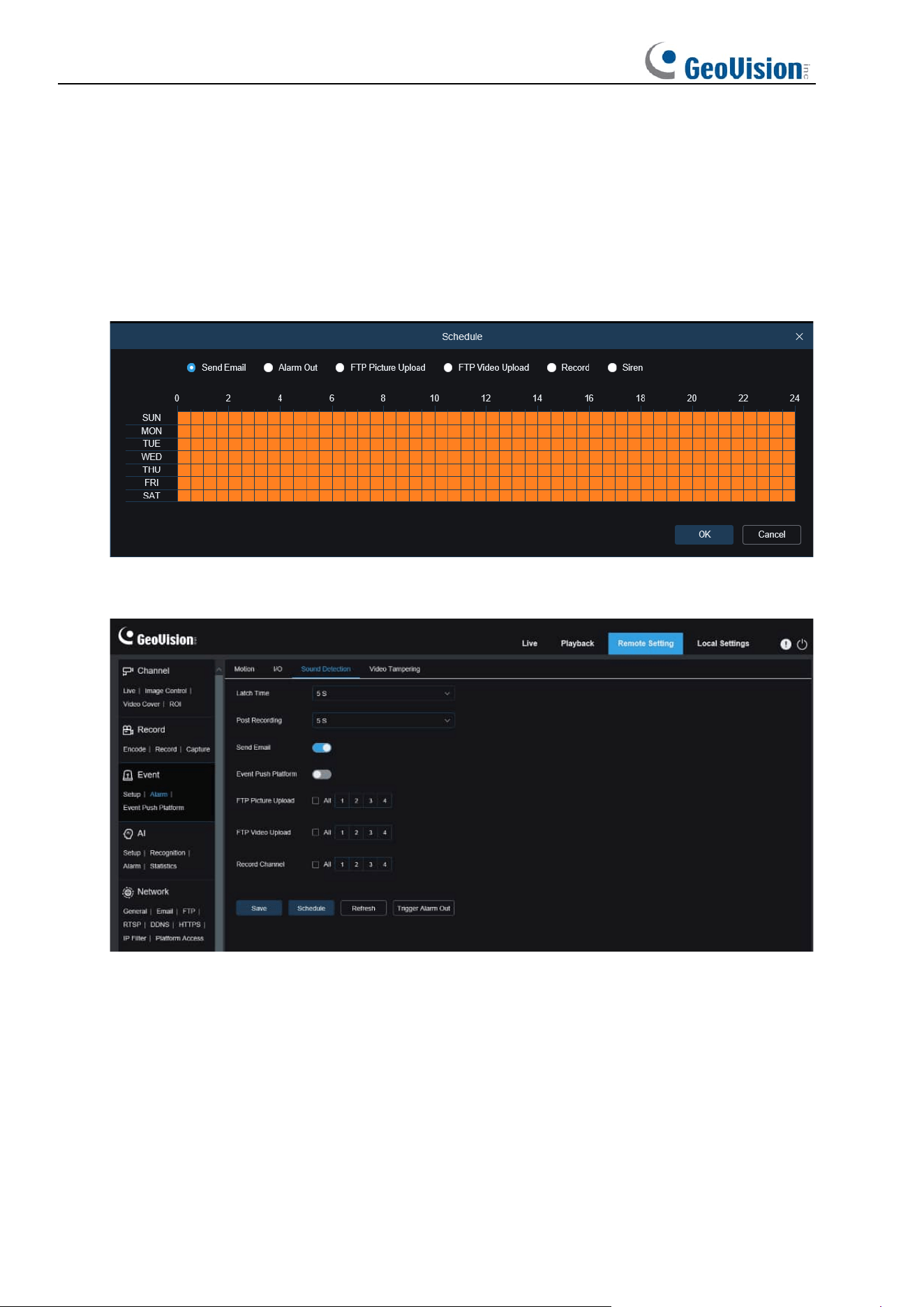
80
Light (only for GV-RMS32810): When this option is enabled, the white light will be turned on
for deterrence when an alarm is triggered.
Record Channel: Recordings of this type will be recorded according to selected channels
when an alarm is triggered (only applicable to GV-RMS32810).
Copy: Users can copy the parameters of the current channel to other channels.
Schedule: Used to set the scheduled time when an alarm acts. A series of alarm actions are
triggered only within the scheduled time.
8.6.2.3 Sound Alarm
Latch Time
: Used to set the duration for triggering an external alarm when a sound alarm is
triggered.
Post Recording
: You can set the duration of continuous recording after an event occurs. The
options include 5s, 10s, 20s, and 30s. The default duration is 5s, but the maximum duration
can be set to 30s.
Send Email:
You can have the device automatically send you an email when it detects a
sound alarm.
FTP Picture Upload: Used to upload alarm pictures to the FTP server. For GV-RMS32810,
you can select the desired channel(s) or all channels.
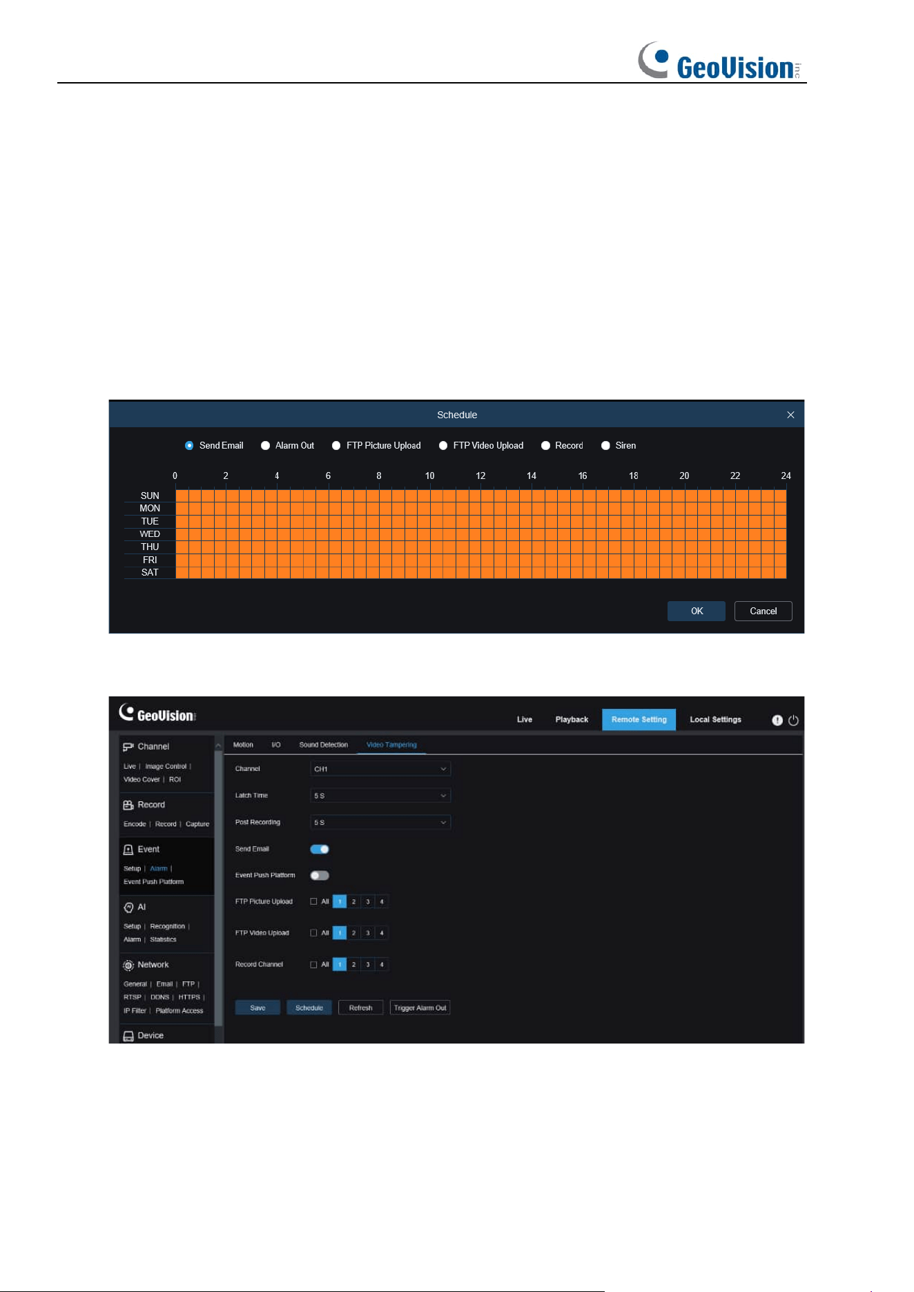
81
FTP Picture Video: Used to upload alarm videos to the FTP server. For GV-RMS32810, you
can select the desired channel(s) or all channels.
Alarm Out: Optional. If your device supports connection to an external alarm device, you can
turn on this switch to activate the external alarm device.
Enable Record: If this option is turned on, this kind of recording will be enabled when an
alarm is triggered.
Record Channel: Recordings of this type will be recorded according to selected channels
when an alarm is triggered (only applicable to GV-RMS32810).
Schedule: Used to set the scheduled time when an alarm acts. A series of alarm actions are
triggered only within the scheduled time.
8.6.2.4 Video Tampering Alarm
Channel: Users can select a channel and set parameters (only applicable to GV-RMS32810).
Latch Time
: Used to set the duration for triggering an external alarm when a video tampering
alarm is triggered.
Post Recording: Specifies the duration of recording after the alarm is cleared.
Note: The effective time is also controlled by the schedule.
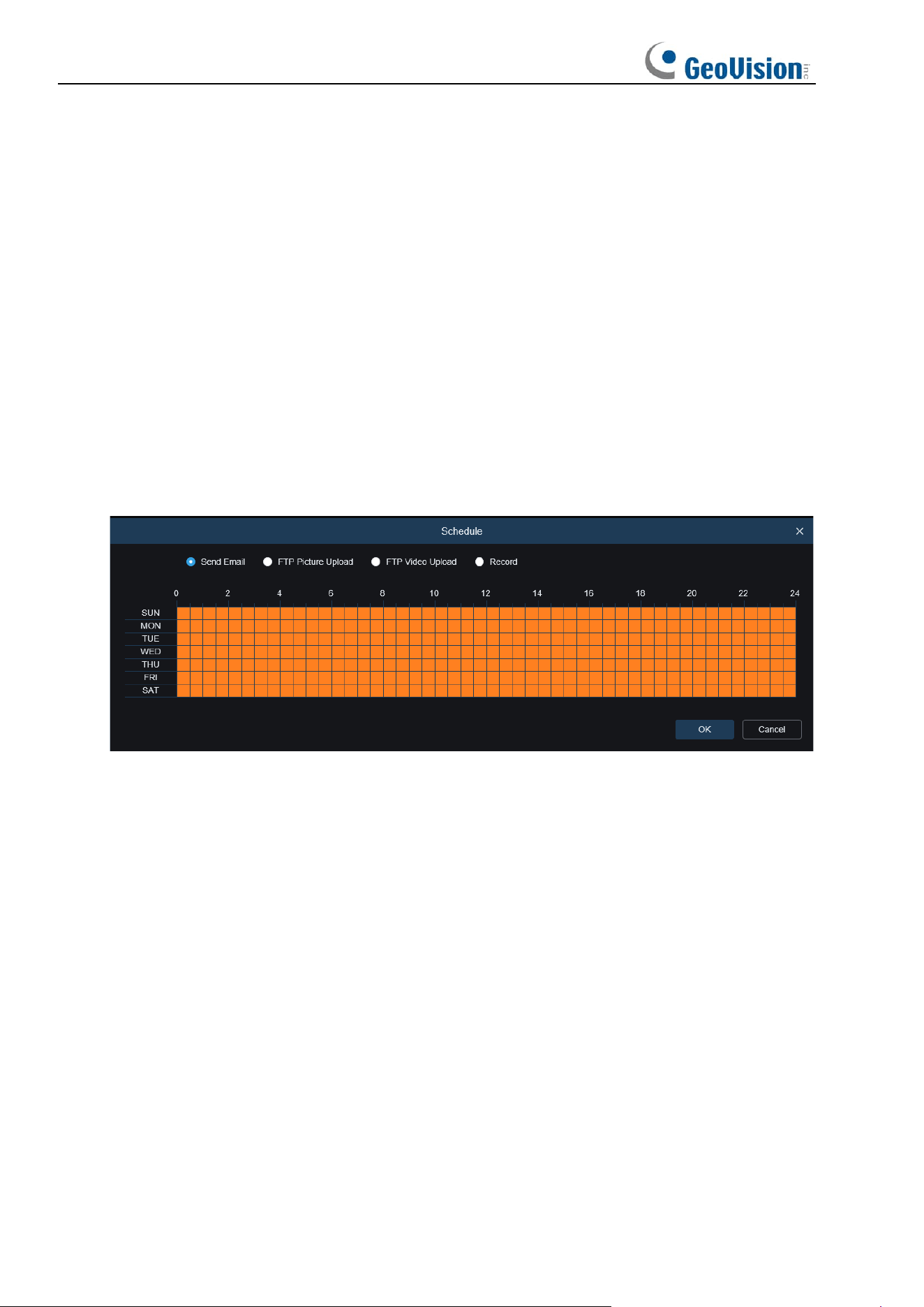
82
Send Email:
You can have the device automatically send you an email when it detects a
sound alarm.
Event Push Platform: If this option is set to ON, this type of information will be pushed to the
client when an alarm is triggered.
FTP Picture Upload: Used to upload alarm pictures to the FTP server. For GV-RMS32810,
you can select the desired channel(s) or all channels.
FTP Video Upload: Used to upload alarm videos to the FTP server. For GV-RMS32810, you
can select the desired channel(s) or all channels.
Alarm Out: Optional. If your device supports connection to an external alarm device, you can
turn on this switch to activate the external alarm device.
Record Channel: Recordings of this type will be recorded according to selected channels
when an alarm is triggered (only applicable to GV-RMS32810).
Schedule: Used to set the scheduled time when an alarm acts. A series of alarm actions are
triggered only within the scheduled time.
(Note: Video tampering alarm is supported in some models).
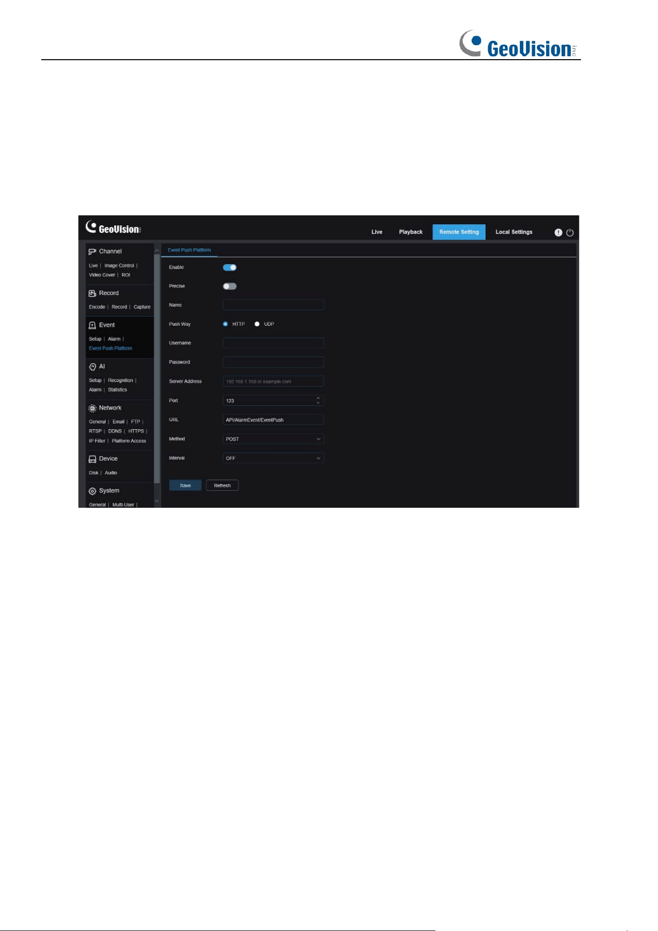
83
8.6.3 Event Push Platform
8.6.3.1 HTTP Push
Events are pushed through HTTP or UDP. The HTTP method includes POST and GET and
the UDP method includes unicast, multicast, and broadcast. (Note: The event push function is
available for some models.)
Enable: Used to enable or disable the event push function.
Precise: Enable or disable. If this option is enabled, the start time and end time will be pushed
when an event is triggered.
Name: Specifies channel name. Chinese characters are not supported.
Push Way: Specifies the way of push. The options include HTTP and UDP and users can
check the HTTP or UDP option as needed.
Username: Specifies the username. This field can be null if no name is available.
Password: Specifies the password. This field can be null if no password is available.
Server Address: Specifies the IP address of the server.
Port: Specifies the port number of the server. (Port No. range: 1 to 65535)
URL: Specifies server API. This field can be null if no API is available.
Method: Specifies the HTTP method. The options include POST and GET: Images can be
pushed only when the HTTP-POST method is selected. In other mode, only messages
without images are pushed. The alarm type regarding images is the same as that in the alarm
push bar in live view on the Web client.
Interval: Specifies the keepalive interval. The keepalive mechanism periodically pushes a
message to the client at the set time without affecting normal alarm push. No keepalive
mechanism is available in UDP.
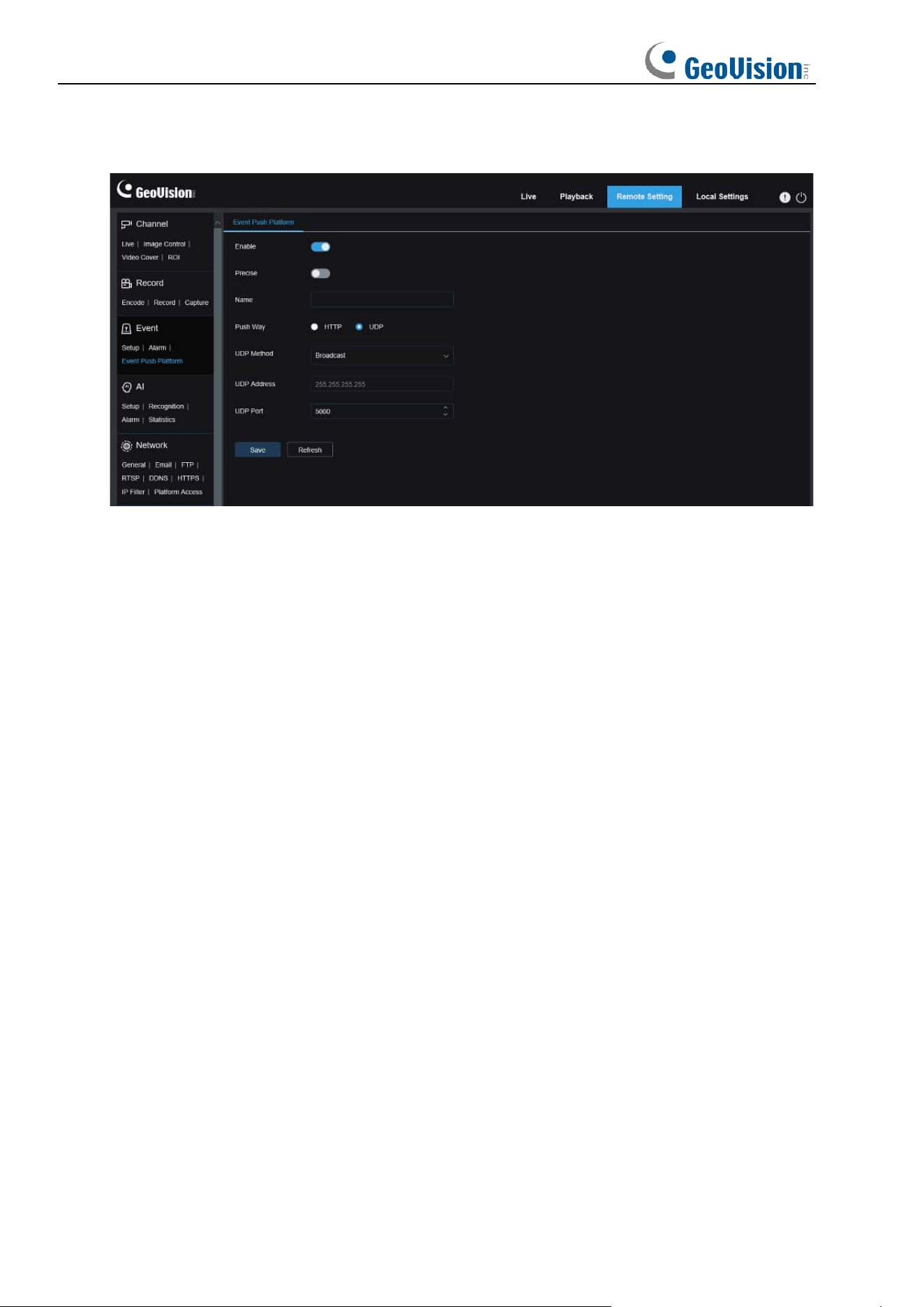
84
8.6.3.2 UDP Push
Enable: Used to enable or disable the event push function.
Precise: Enable or disable. If this option is enabled, the start time and end time will be pushed
when an event is triggered.
Name: Specifies channel name. Chinese characters are not supported.
Push Way: Specifies the way of push. The options include HTTP and UDP and users can
check the HTTP or UDP option as needed.
UDP Method: Specifies the type of UDP push. The options include Unicast, Multicast, and
Broadcast.
Unicast: Users can receive push messages simply by enter the IP address and port
number of the UDP server on the client and only this address can receive messages.
Multicast: Multiple UDP servers on the client using the same UDP address and port
number in the same network segment will receive messages while addresses other than
this UDP address will not receive messages.
Broadcast: All UDP servers in the network segment will receive messages.
UDP Address: Specifies the IP address of a UDP server.
UDP Port: Specifies the port number of a UDP server (value range: 1 to 65535).
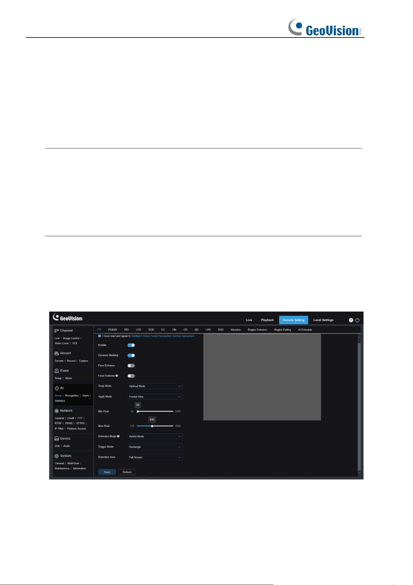
85
8.7 AI
8.7.1 Setup
To use the AI alarm function, enable the alarm function in the Setup menu. Enabling the
function consumes the computing power of the camera.
Note:
1. For GV-RBL5800 / 5811 / REB5800: Due to the limited performance of the camera,
HM, RSD, Intrusion, and Region Entrance / Exiting and other functions can be enabled
at the same time but not PID, LCD, SOD, FD, PD&VD, CC, CD, QD.
2. For GV-RMS32810: Due to the limited performance of the camera, HM, Intrusion,
Region Entrance / Exiting, LCD, and other functions can be enabled at the same time
but not SOD, FD, PD&VD, CC, CD, QD.
8.7.1.1 FD
Face detection function. First, the camera detects the face and obtain the capture image that
meets the requirements. Then, the face feature data of the capture image is calculated by the
face model algorithm and then compared with that in the face database. Finally, an alarm is
triggered. To do this, you need to enable the face detection function.
Channel: Users can select a channel and set parameters (only applicable to GV-RMS32810).
Enable: Used to enable the face detection function.
Dynamic Marking: Displays the face detection box and used to turn on or off the detection
rule line.
Face Enhance: Face enhancement switch to increase the capture effect of moving objects. It

86
will also adjust the brightness of the recognized face closest to the camera to optimize the
capture effect.
Face Features: Used to recognize the features of the detected face image, including age,
gender, mask, glasses, expression, and so on. Note: To use the AD alarm, enable this
function.
Snap Mode: Used to set the snap mode. You can receive push notifications in live view or
connect an NVR to check the image effect. The program supports three Snap Modes.
Optimal Mode: The camera only pushes an image that it considers best from detecting
an object until the object disappears.
RealTime Mode: When detecting an object, the camera immediately pushes an image,
and then pushes the best image when the object disappears.
Interval Mode: Used to set the snap number and the snap and push interval as required.
The options for Snap Num include 1, 2, 3, and unlimited. The Snap Frequency ranges
from 1s to 255s. For example, when the snap frequency is set to 5s, an image is pushed
at 5s, 10s and 15s when the object is detected.
Apply Mode: Used to screen the captured images. That is, only the captured images that
meet angle setting will be pushed. There are three mode options.
Frontal View: Only the frontal view of an object is pushed.
Multi Angle: You can choose to push images containing only side faces.
Customize: Used to customize the angle of an object for which images can be pushed. If
this function is enabled, Roll Range, Pitch Range, Yaw Range, and Picture Quality
options, as well as Frontal Default and Multi Default buttons will be available.
Roll Range: Used to set the roll range of the captured face image in the 3D model. When
the angle does not meet the setting limit, face detection can be carried out but the image
will not be pushed.
Pitch Range: Used to set the pitch range of the captured face image in the 3D model.
When the angle does not meet the setting limit, face detection can be carried out but the
image will not be pushed.
Yaw Range: Used to set the yaw angle of the captured face image in the 3D model.
When the angle does not meet the setting limit, face detection can be carried out but the
image will not be pushed.
Picture Quality: High quality images are good for filtering out detected non-face images.
Min Pixel: Based on the 1080p resolution, filter out faces lower than the setting in the snap
screen. The default resolution is 64×64 pixels, and the setting range is 32 to 1080 pixels.

87
Max Pixel: Based on the 1080p resolution, filter out faces greater than the setting in the snap
screen. The default resolution is 640×640 pixels, and the setting range is 320 to 1080 pixels.
Detection Mode: Used to filter the performance of detected objects in the camera. There are
two mode options.
Hybrid Mode: Allows you do face detection for all objects in the view.
Motion Mode: Allows you to filter out motionless faces, such as such as portraits and
statues in the scene.
Trigger Mode: Used to set the detection rule line type. There are two rule types.
Rectangle: Allows you to detect only face objects in the set area.
Line: In this mode, face objects are tracked only when the detection line is crossed
according to settings.
Detection Area: Setting options are changed when the detection area is used to recognize
objects by default. There are two modes.
Full Screen: All areas that can be monitored by the camera are detected.
User-defined: Only the areas selected in quadrilateral boxes are detected.
The Rule Type setting option is available only when the line-crossing detection mode is used.
There are A→B and B→A detection Trigger Modes.
Frontal Default Apply Mode: This control is displayed when Customize is selected. Set the
angles of the image to be pushed as follows: Range: 30, Pitch Range: 30, Yaw Range: 45,
Picture Quality: 100
Multi Default Apply Mode: This control is displayed when Customize is selected. Set the
angles of the image to be pushed as follows: Range: 180, Pitch Range: 180, Yaw Range: 180,
Picture Quality: 100
Rule Line Setting Area: You can set the quadrilateral detection area or detection triggering
line in this area according to parameter settings.
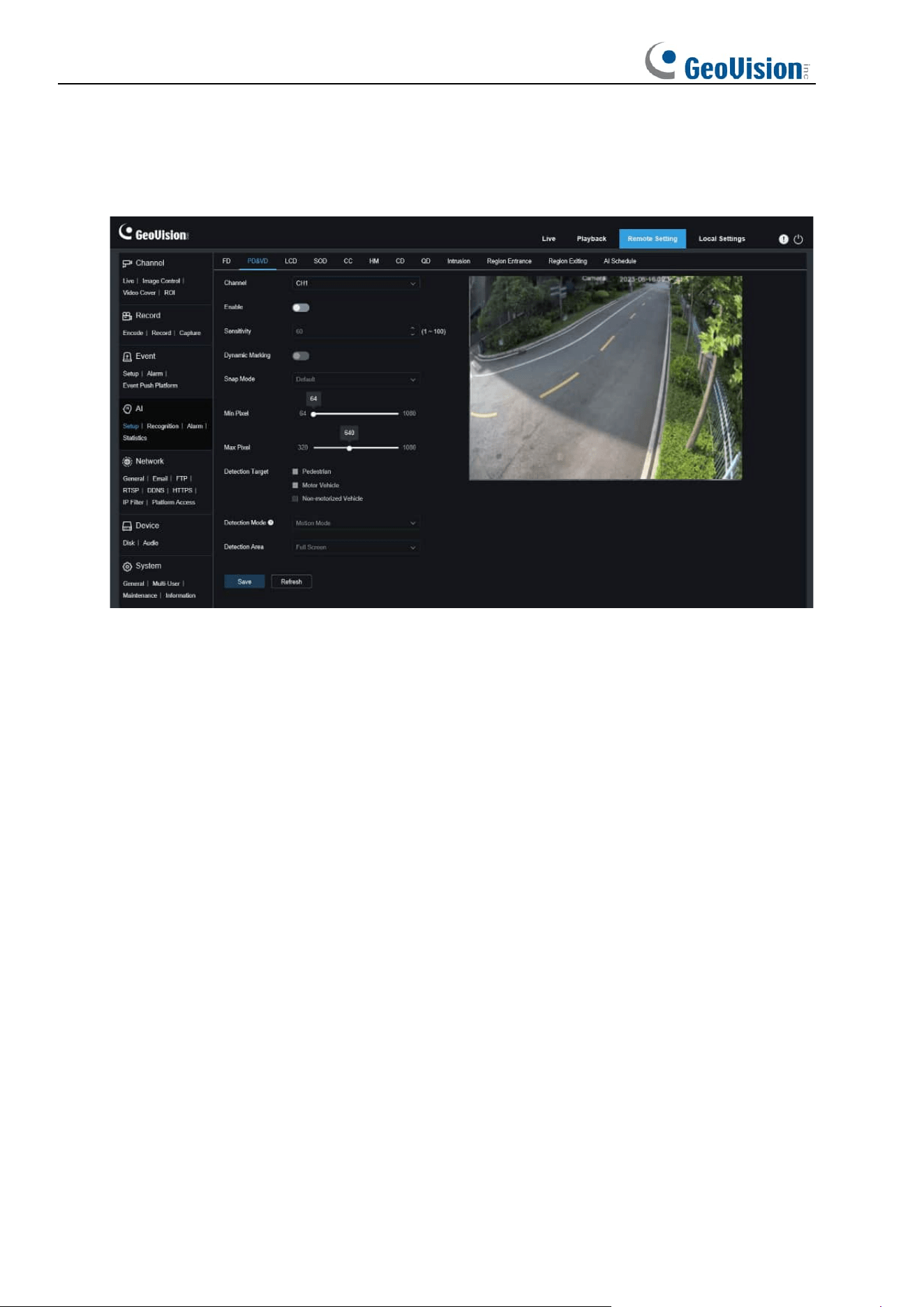
88
8.7.1.2 PD&VD
Pedestrian detection and vehicle detection function, used to recognize pedestrian or vehicles
in the view, generate an alarm, and record capture images, according function settings.
Channel: Users can select a channel and set parameters (only applicable to GV-RMS32810).
Enable: Used to enable the pedestrian and vehicle detection function.
Sensitivity: With higher detection sensitivity, pedestrian or vehicle objects can be detected
easier, but false alarms may be easily generated.
Dynamic Marking: Displays the pedestrian and vehicle detection box and used to turn on or
off the detection rule line.
Snap Mode: Used to set the snap mode. You can receive push notifications in live view or
connect an NVR to check the image effect. The program supports three Snap Modes.
Default: The camera pushes only one pedestrian or vehicle image from detecting an
object until the object disappears.
RealTime Mode: When detecting an object, the camera immediately pushes one image,
and then pushes another image when the object disappears.
Interval Mode: Used to push images at a set interval.
Snap Num: Images for the same object as determined by the camera will be pushed 1, 2,
3, or unlimited times at an interval set in Snap Frequency.
Snap Frequency: Images will be pushed based on the set time upon appearance of an
object or since the last push.
Min Pixel: Based on the 1080p resolution, filter out pedestrian or vehicle objects lower than
the setting in the view.

89
Max Pixel: Based on the 1080p resolution, filter out pedestrian or vehicle objects greater than
the setting in the view.
Detection Target: The options include pedestrian, motor vehicle, non-motorized vehicle, and
all.
Detection Mode: Used to filter object behaviors in the detection area. There are two mode
options.
Static Mode: Allows you to detect all pedestrians or vehicles in the view.
Motion Mode: Allows you to filter out motionless pedestrians or vehicles.
Detection Area: Detection area setting. There are two mode options:
Full Screen: All areas that can be monitored by the camera are detected.
User-defined: Only the areas selected in quadrilateral boxes are detected.
Rule Line Setting Area: Allows you to configure detection settings in this area when the
custom detection area mode is used.
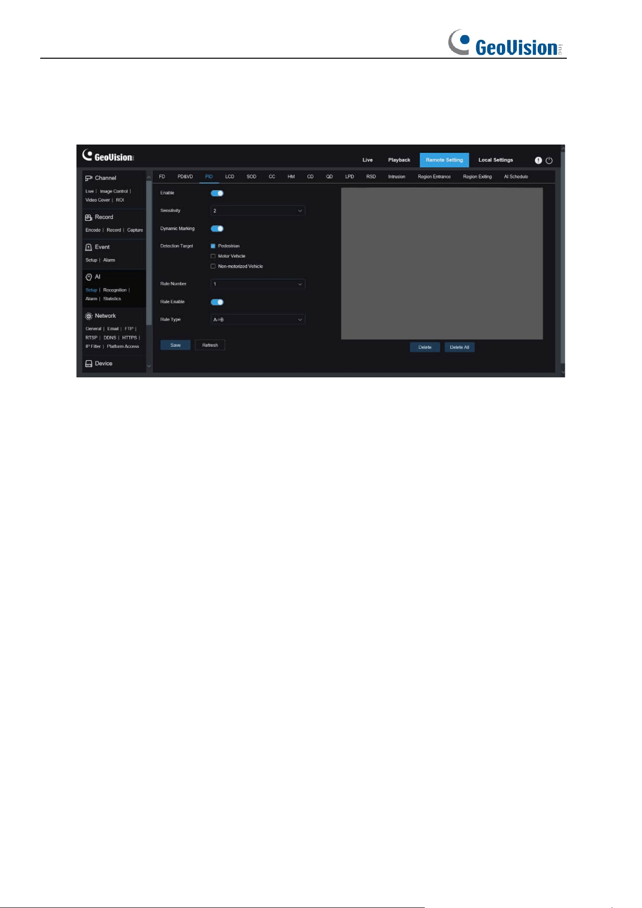
90
8.7.1.3 PID
Perimeter intrusion detection. An alarm is triggered when a specific object enters or leaves the
warning area.
Enable: Used to turn on or off the perimeter intrusion alarm function.
Sensitivity: Used to filter small disturbing objects. The higher the sensitivity, the smaller the
object can be detected.
Dynamic Marking: Displays the detection box and used to turn on or off the detection rule
line.
Detection Target: Used to set objects for perimeter intrusion detection:
Pedestrian: An alarm is triggered when a pedestrian intrudes the perimeter.
Motor Vehicle: An alarm is triggered when a motor vehicle intrudes the perimeter.
Non-motorized Vehicle: An alarm is triggered when a non-motorized vehicle intrudes the
perimeter.
Rule Number: Allows you to select a rule line number. The PID function allows you to set four
detection rule lines.
Rule Enable: Used to turn on or off rule lines. Each rule line has an independent enable
switch that is associated with the currently selected Rule Number.
Rule Type: Specifies the rule to trigger rule lines. There are A→B, B→A, and A←→B
line-crossing rules whose settings are related to the currently selected Rule Number.
Rule Line Setting Area: Allows you to set and view edited rule lines.
Delete: Allows you to delete selected rule Lines in the rule line setting area.
Delete All: Allows you to delete all rule lines.
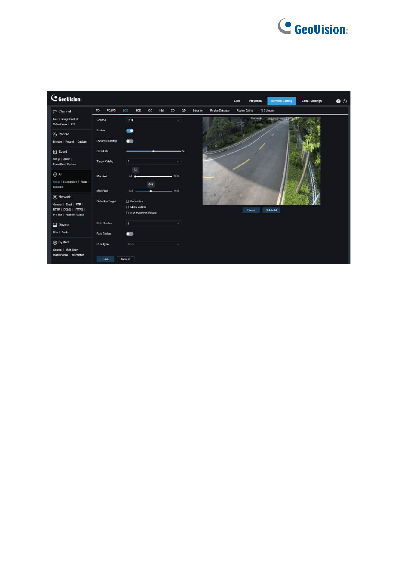
91
8.7.1.4 LCD
Line-crossing detection function. An alarm is triggered when a specific object crosses the
preset detection line.
Channel: Users can select a channel and set parameters (only applicable to GV-RMS32810).
Enable: Used to enable the line-crossing detection function.
Sensitivity: Used to filter small disturbing objects. The higher the sensitivity, the smaller the
object can be detected.
Dynamic Marking: Displays the detection box and used to turn on or off the detection rule
line.
Target Validity: Used to adjust the detection validity of the target. The higher the validity, the
more closely the target matches the set criteria, for example, a motor vehicle. However,
higher validity levels also increase the risk of false negatives, while lower validity values may
lead to false positives. The range is from 1 to 4, with lower values indicating higher confidence
levels.
Detection Target: Used to set objects for perimeter intrusion detection:
Pedestrian: A perimeter intrusion alarm is triggered only for pedestrians.
Motor Vehicle: A perimeter intrusion alarm is triggered only for motor vehicles.
Non-motorized Vehicle: A perimeter intrusion alarm is triggered only for non-motorized
vehicles.
Rule Number: Allows you to select a rule line number. The LCD function allows you to set
four detection rule lines.
Rule Enable: Used to turn on or off rule lines. Each rule line has an independent enable
switch that is associated with the currently selected Rule Number.
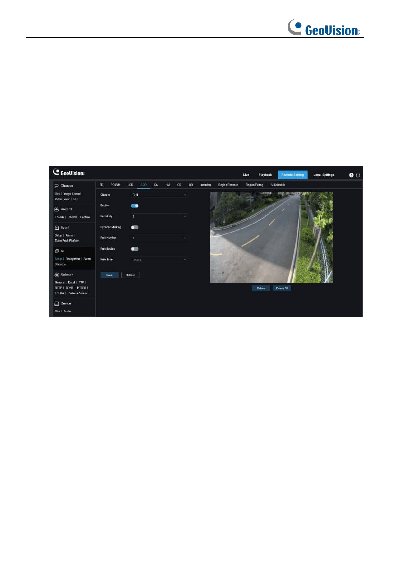
92
Rule Type: Specifies the rule to trigger rule lines. There are A→B, B→A, and A←→B
line-crossing rules whose settings are related to the currently selected Rule Number.
Rule Line Setting Area: Allows you to set, modify, and view edited rule lines.
Delete: Allows you to delete selected rule Lines in the rule line setting area.
Delete All: Allows you to delete all rule lines.
8.7.1.5 SOD
Stationary object detection. An alarm will be triggered when there are items left or lost in the
monitored scene.
Channel: Users can select a channel and set parameters (only applicable to GV-RMS32810).
Enable: Used to turn on or off the SOD function.
Sensitivity: Used to filter small disturbing objects. The higher the sensitivity, the smaller the
object can be detected.
Dynamic Marking: Displays the detection box and used to turn on or off the detection rule
line.
Rule Number: Allows you to select a rule line number. The LCD function allows you to set
four detection rule lines.
Rule Enable: Used to turn on or off rule lines. Each rule line has an independent enable
switch that is associated with the currently selected Rule Number.
Rule Type: Specifies the rule to trigger rule lines. You can set to trigger an alarm when an
item is left or lost in the detection area. There are three rules including Legacy, Lost, and Lost
& Legacy whose settings are related to the currently selected Rule Number.
Rule Line Setting Area: Allows you to set, modify, and view edited rule lines.
Delete: Allows you to delete selected rule Lines in the rule line setting area.
Delete All: Allows you to delete all rule lines.
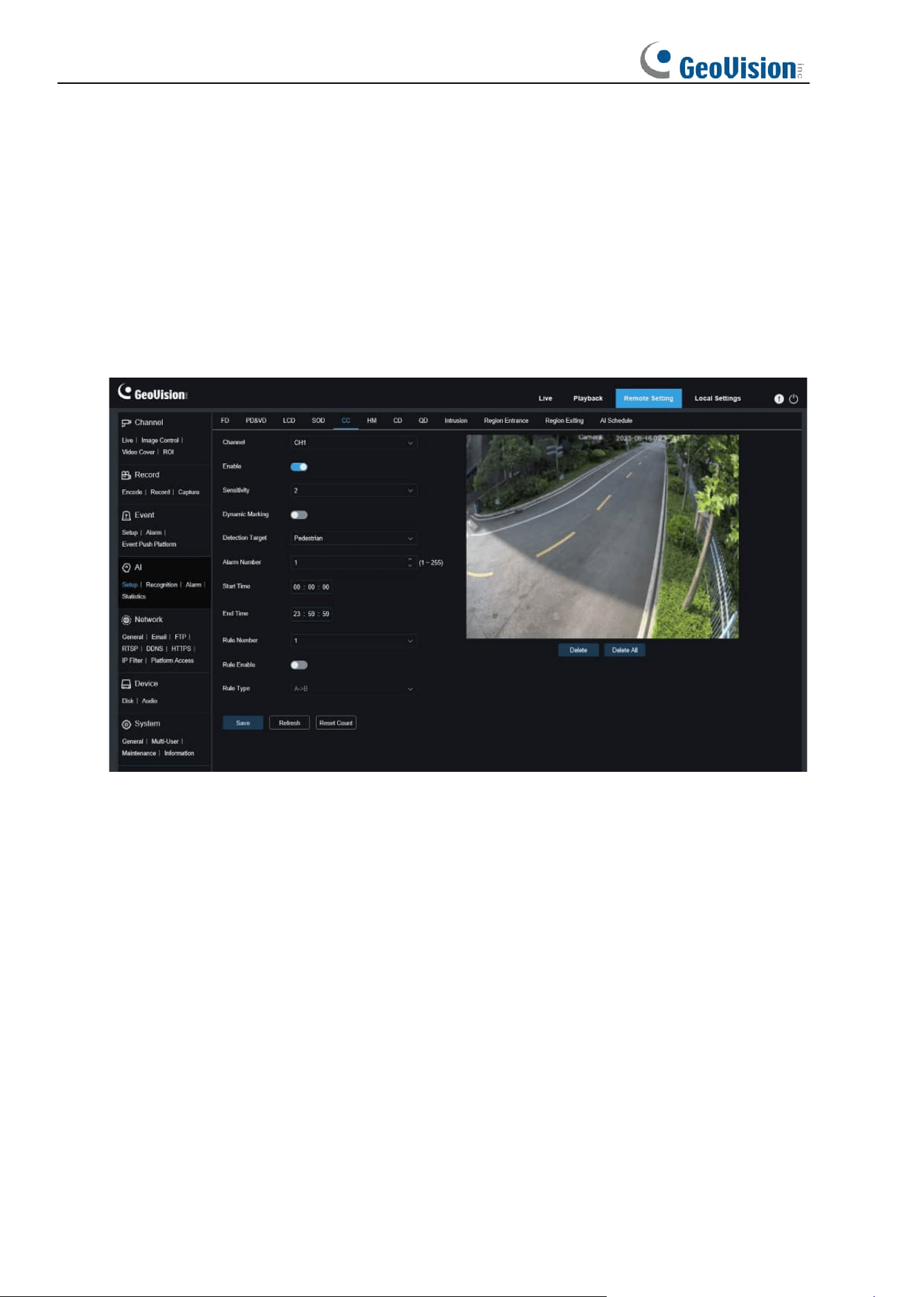
93
8.7.1.6 CC
Cross counting (CC) statistics function. Used to record the line-crossing information of a
specific object in the monitored area. Set a crossing line. There are A and B areas on two
sides of the set line. For example, the triggering rule for the rule line is A→B. When an object
enters from area A and crosses the detection line, in is increased by 1 when the object leaves
area B. When the object enters from area B and crosses the detection line, out is increased by
1 when the object leaves area A. When the increase is to be calculated, an alarm is triggered
only when the current IN count minus the out count is greater than or equal to the set Alarm
Number, as shown in the following figure.
Channel: Users can select a channel and set parameters (only applicable to GV-RMS32810).
Enable: Used to enable the cross counting (CC) statistics function.
Sensitivity: Used to filter small disturbing objects. The higher the sensitivity, the smaller the
object can be detected. This can also be used to detect distant objects in the scene.
Dynamic Marking: Displays the detection box and used to turn on or off the detection rule
line.
Detection Target: Used to set the type of objects to be recognized in the cross counting (CC)
detection. There are three modes. Switchover or saving operation will clear the current count.
Motion: All objects, including pedestrians, vehicles, and cartons, will be detected.
Pedestrian: Only pedestrian objects will be recognized.
Motor Vehicle: Only motor vehicle objects will be recognized.
Non-motorized Vehicle: Only non-motorized vehicle objects will be recognized.
Alarm Number: Used to set conditions to trigger an alarm. The camera will trigger a CC
alarm when the count is updated and the in count minus the out count is greater or equal to
the current setting.

94
Start Time: The time when the line-crossing detection function starts to work every day.
End Time: The time when the line-crossing detection function stops working every day.
Rule Number: Rule line number. Only one detection rule line is supported for cross counting
(CC).
Rule Enable: Used to turn on or off the current rule line.
Rule Type: Used to set the direction to increase the in/out trigger count, that is, A→B and
B→A. For example, if A→B is selected, the in count increases when the monitored object
enters area A and leaves area B, and the out count increases when the monitored object
enters area B and leaves area A.
Reset Count: Used to clear the currently displayed count.
Line-crossing Setting Area: Allows you to set the rule line for cross counting (CC) detection
in this area.
Count Area: Displays cross counting (CC) statistics.
95
8.7.1.7 HM
Heat map. You can set all areas or a specific area to detect the people activity information in
the specified area. You can also save and upload changes at an interval of 10 minutes. The
heat map can intuitively present people distribution in temporal and spatial dimensions for
good understanding of activity degrees in each area in the scene. This function only supports
data recording, not alarming.
Channel: Users can select a channel and set parameters (only applicable to GV-RMS32810).
Enable: Used to turn on or off the HM statistics.
Rule Number: Rule line number. Only one detection rule line is supported for HM.
Rule Enable: Used to turn on or off the current rule line.
Monitoring Area Setting: Used to set the areas for collecting heat statistics. By default, all
areas are selected.
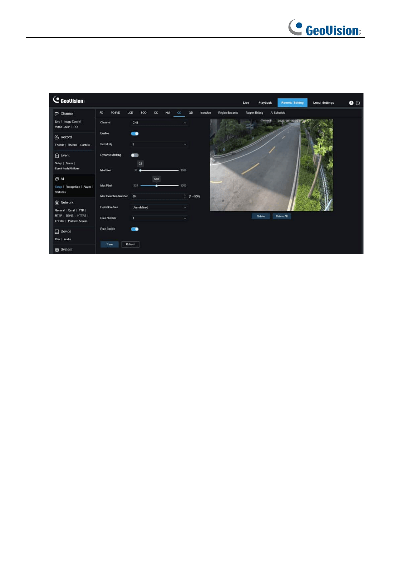
96
8.7.1.8 CD
Crowd detection function. Perform people counting and identify number of people in the
monitored area. An alarm is triggered when the number of people exceeds the preset value.
Channel: Users can select a channel and set parameters (only applicable to GV-RMS32810).
Enable: Used to turn on or off the crowd detection function.
Sensitivity: Used to filter small disturbing objects. The higher the sensitivity, the smaller the
object can be detected.
Dynamic Marking: Displays the detection box and used to turn on or off the detection rule
line.
Min Pixel: Based on the 1080p resolution, filter out objects with heads smaller than the
setting in the view.
Max Pixel: Based on the 1080p resolution, filter out objects with heads larger than the setting
in the view.
Max Detection Number: Maximum number of heads that can be detected in the detection
area. An alarm will be triggered when this value is exceeded.
Detection Area: Used to set the area where the crowd detection function will be applied.
There are two modes.
Full Screen: In this mode, all areas covered by the camera will be detected.
User-defined: Allows you to customize detection areas.
Rule Number: Rule line number. This number is displayed when you set a custom detection
area. One detection rule line is supported.
Rule Enable: Used to turn on or off the current rule line. This switch is displayed when you set
a custom detection area.
Detection Area Setting: This setting is available when you set a custom detection area. An
octagonal detection area needs to be set.
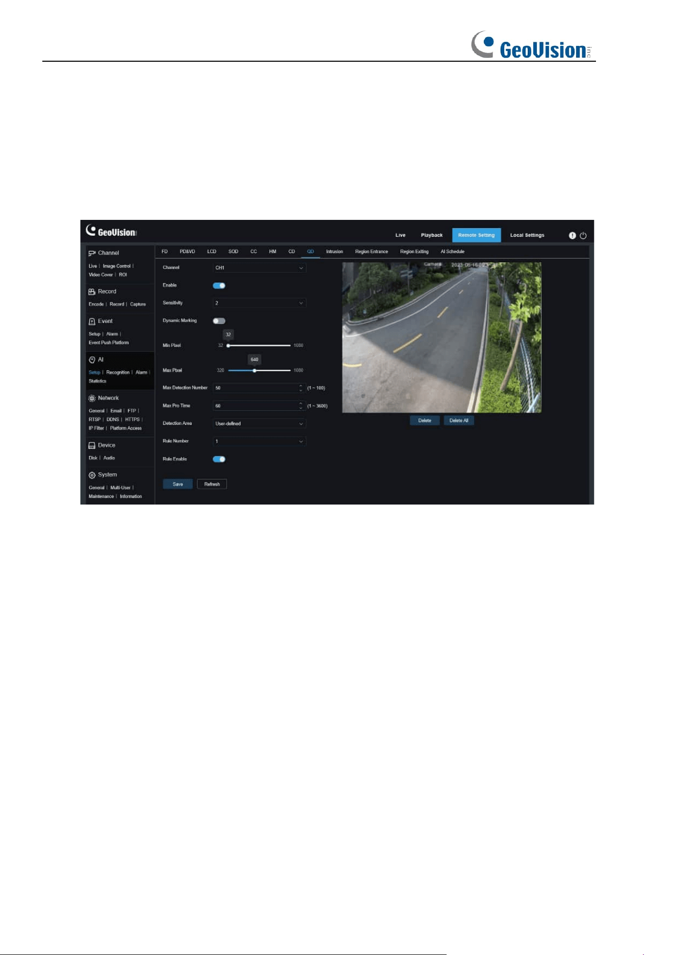
97
Count Display Area: Displays the number of people in the current monitored area. For
adjustment of display location.
8.7.1.9 QD
Queue detection function. Used to set the people number in the queue and wait time. An
alarm will be triggered when the queue is too long or the wait time is too long.
Channel: Users can select a channel and set parameters (only applicable to GV-RMS32810).
Enable: Used to turn on or off the queue detection function.
Sensitivity: Used to filter small disturbing objects. The higher the sensitivity, the smaller the
object can be detected.
Dynamic Marking: Displays the detection box and used to turn on or off the detection rule
line.
Min Pixel: Based on the 1080p resolution, filter out objects with heads smaller than the
setting in the view.
Max Pixel: Based on the 1080p resolution, filter out objects with heads larger than the setting
in the view.
Max Detection Number: Maximum number of heads that can be detected in the detection
area. An alarm will be triggered when this value is exceeded.
Max Pro Time: The maximum duration allowed for people to stay in the detection area. An
alarm will be triggered when the set duration is exceeded and no one leaves the detection
area. (This duration starts from the time when the last person leaves the detection area. If no
one leaves within the set duration, the processing will be considered as timeout and an alarm
will be triggered.)

98
Note: Counting is restarted only when a target leaves the detection area. Counting will be
ignored if the target in the area suddenly disappears. Counting is started only if a target is
detected in the detection area.
Detection Area: Used to set the area where the queue detection function will be applied.
There are two modes.
Full Screen: In this mode, all areas covered by the camera will be detected.
User-defined: Allows you to customize detection areas.
Rule Number: Rule line number. This number is displayed when you set a custom detection
area. One detection rule line is supported.
Rule Enable: Used to turn on or off the current rule line. This switch is displayed when you set
a custom detection area.
Detection Area Setting: This setting is available when you set a custom detection area. An
octagonal detection area needs to be set.
Count Display Area: Displays the number of people in the current monitored area and queue
time. For adjustment of display location.
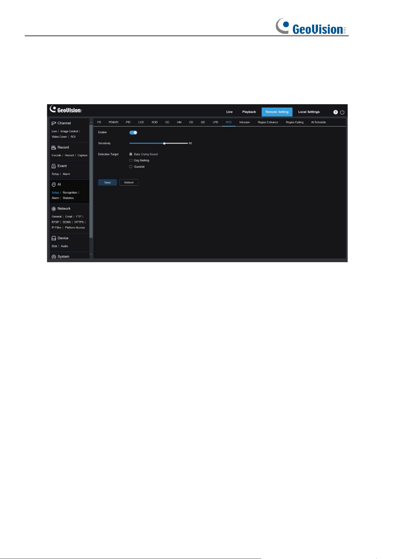
99
8.7.1.10 RSD
Sound exception detection. Here you can set different detection requirements depending on
application requirements, for example, baby crying sound, gunshot, and dog barking. An
alarm will be triggered when the camera detects the set sound.
Enable: Used to turn on or off the sound exception detection function.
Sensitivity: Sensitivity. 1 indicates the minimum setting and 100 indicates the maximum
setting.
Detection Type: Specifies detection type.
Baby Crying Sound: A baby crying sound can be detected if this box is checked.
Dog Barking: A dog barking sound can be detected if this box is checked.
Gunshot: A gunshot sound can be detected if this box is checked.
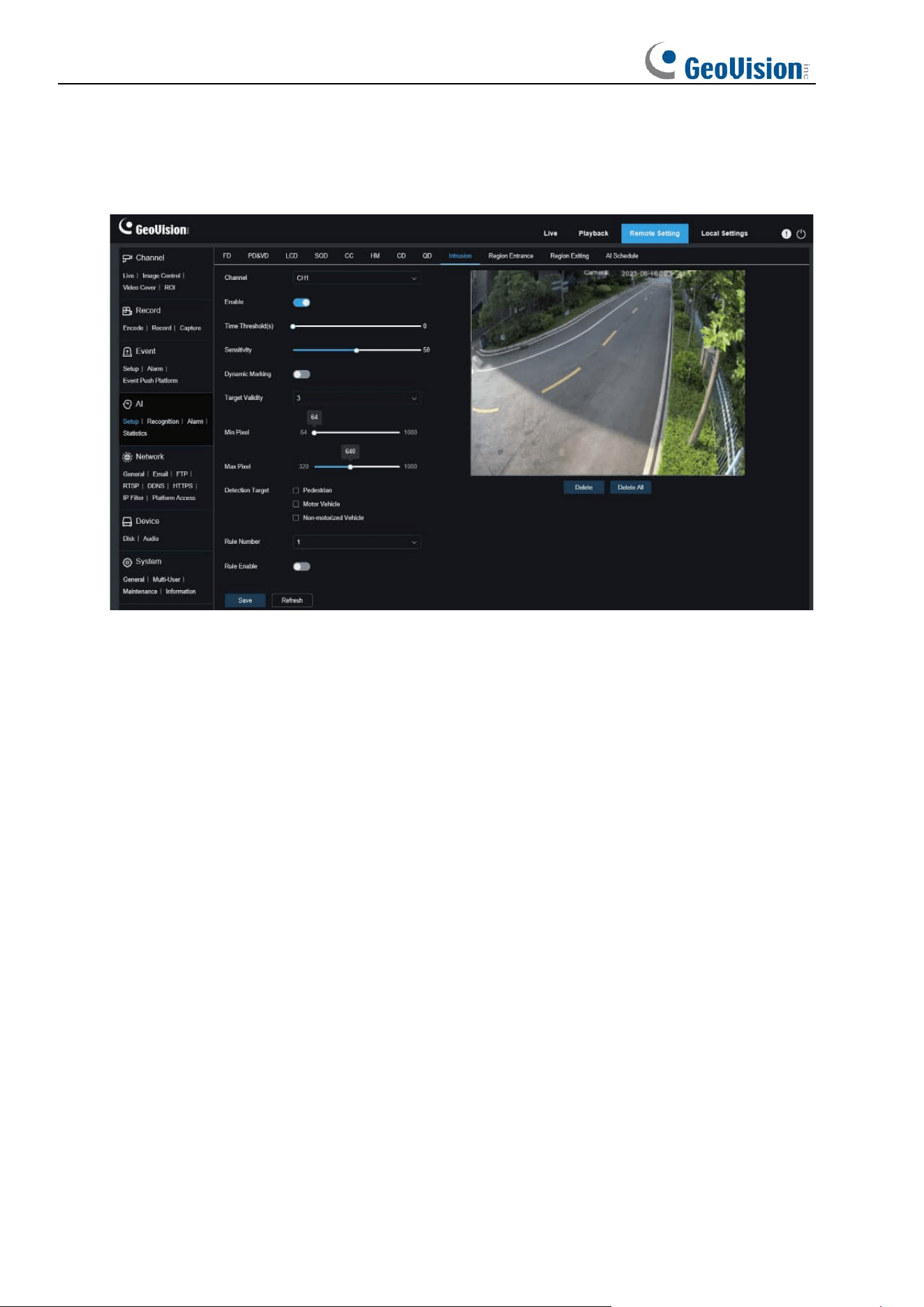
100
8.7.1.11 Intrusion
An alarm is triggered when a specific object enters the warning area over the set time
threshold.
Channel: Users can select a channel and set parameters (only applicable to GV-RMS32810).
Enable: Used to turn on or off the intrusion alarm function.
Time Threshold(s): The minimum period of time for an object to stay within the detection
area before an alarm is triggered.
Sensitivity: Used to filter small disturbing objects. The higher the sensitivity, the smaller the
object can be detected.
Dynamic Marking: Displays the detection box and used to turn on or off the detection rule
line.
Target Validity:
Used to adjust the detection validity of the target. The higher the validity, the
more closely the target matches the set criteria, for example, a motor vehicle. However,
higher validity levels also increase the risk of false negatives, while lower validity values may
lead to false positives. The range is from 1 to 4, with lower values indicating higher confidence
levels.
Min Pixel: Based on the 1080p resolution, filter out pedestrian or vehicle objects lower than
the setting in the view.
Max Pixel: Based on the 1080p resolution, filter out pedestrian or vehicle objects greater than
the setting in the view.
Detection Target:
Used to set objects for intrusion detection:
Pedestrian: An alarm is triggered when a pedestrian intrudes the detection area.
Motor Vehicle: An alarm is triggered when a motor vehicle intrudes the detection area.
Non-motorized Vehicle: An alarm is triggered when a non-motorized vehicle intrudes the
detection area.
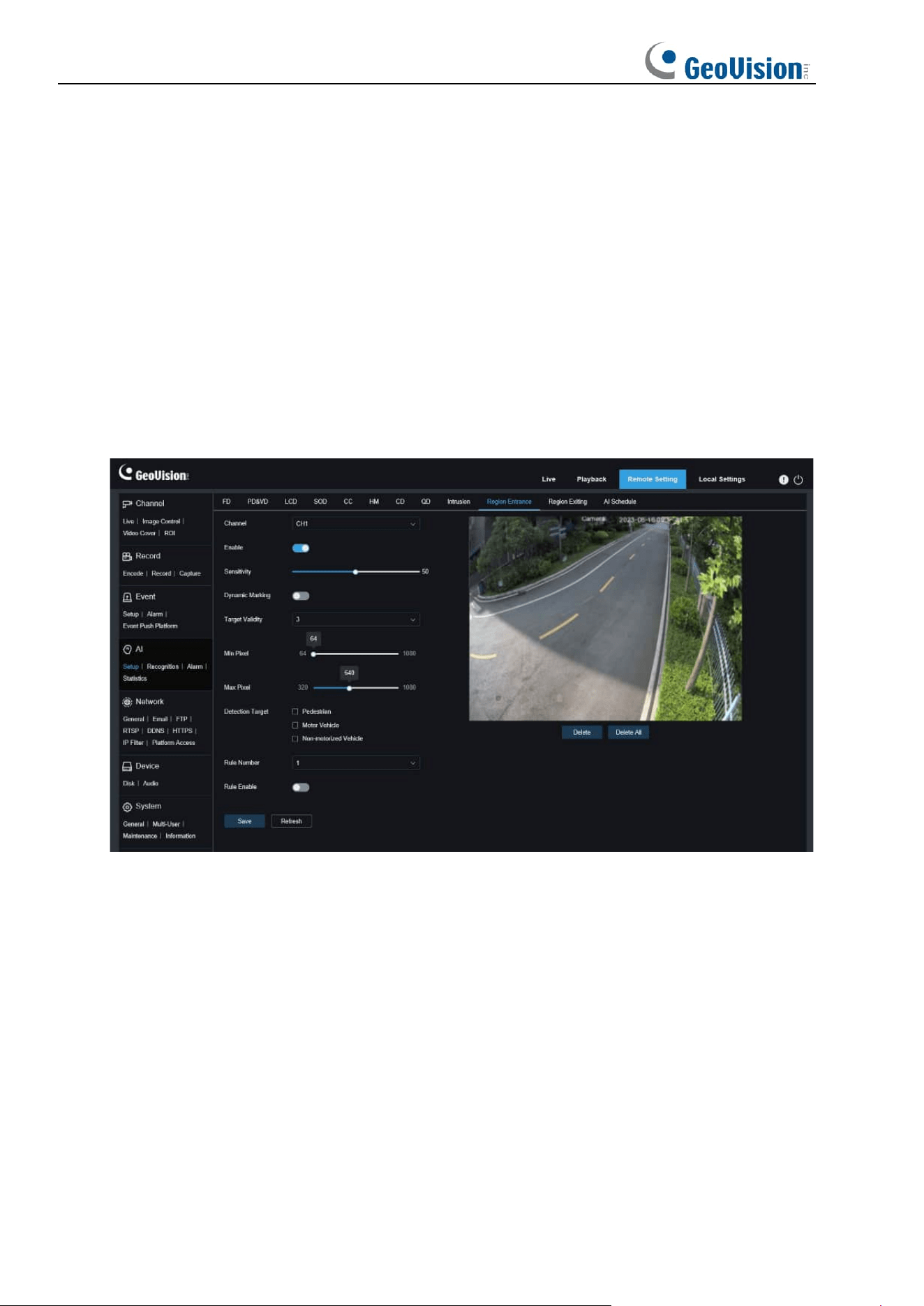
101
Rule Number: Allows you to select a rule line number. The intrusion function allows you to set
four detection rule lines.
Rule Enable: Used to turn on or off rule lines. Each rule line has an independent enable
switch that is associated with the currently selected Rule Number.
Rule Type: Specifies the rule to trigger rule lines.
Rule Line Setting Area: Allows you to set and view edited rule lines.
Delete: Allows you to delete selected rule Lines in the rule line setting area.
Delete All: Allows you to delete all rule lines.
8.7.1.12 Region Entrance / Exiting
With Region Entrance / Exiting, an alarm is generated when a person or vehicle enters /
leaves the boundaries of the detection area.
Channel: Users can select a channel and set parameters (only applicable to GV-RMS32810).
Enable: Used to turn on or off the alarm function.
Sensitivity: Used to filter small disturbing objects. The higher the sensitivity, the smaller the
object can be detected.
Dynamic Marking: Displays the detection box and used to turn on or off the detection rule
line.
Target Validity:
Used to adjust the detection validity of the target. The higher the validity, the
more closely the target matches the set criteria, for example, a motor vehicle. However,
higher validity levels also increase the risk of false negatives, while lower validity values may
lead to false positives. The range is from 1 to 4, with lower values indicating higher confidence
levels.
Min Pixel: Based on the 1080p resolution, filter out pedestrian or vehicle objects lower than
the setting in the view.

102
Max Pixel: Based on the 1080p resolution, filter out pedestrian or vehicle objects greater than
the setting in the view.
Detection Target:
Used to set objects for intrusion detection:
Pedestrian: An alarm is triggered when a pedestrian intrudes the detection area.
Motor Vehicle: An alarm is triggered when a motor vehicle intrudes the detection area.
Non-motorized Vehicle: An alarm is triggered when a non-motorized vehicle intrudes the
detection area.
Rule Number: Allows you to select a rule line number. The intrusion function allows you to set
four detection rule lines.
Rule Enable: Used to turn on or off rule lines. Each rule line has an independent enable
switch that is associated with the currently selected Rule Number.
Rule Line Setting Area: Allows you to set and view edited rule lines.
Delete: Allows you to delete selected rule Lines in the rule line setting area.
Delete All: Allows you to delete all rule lines.
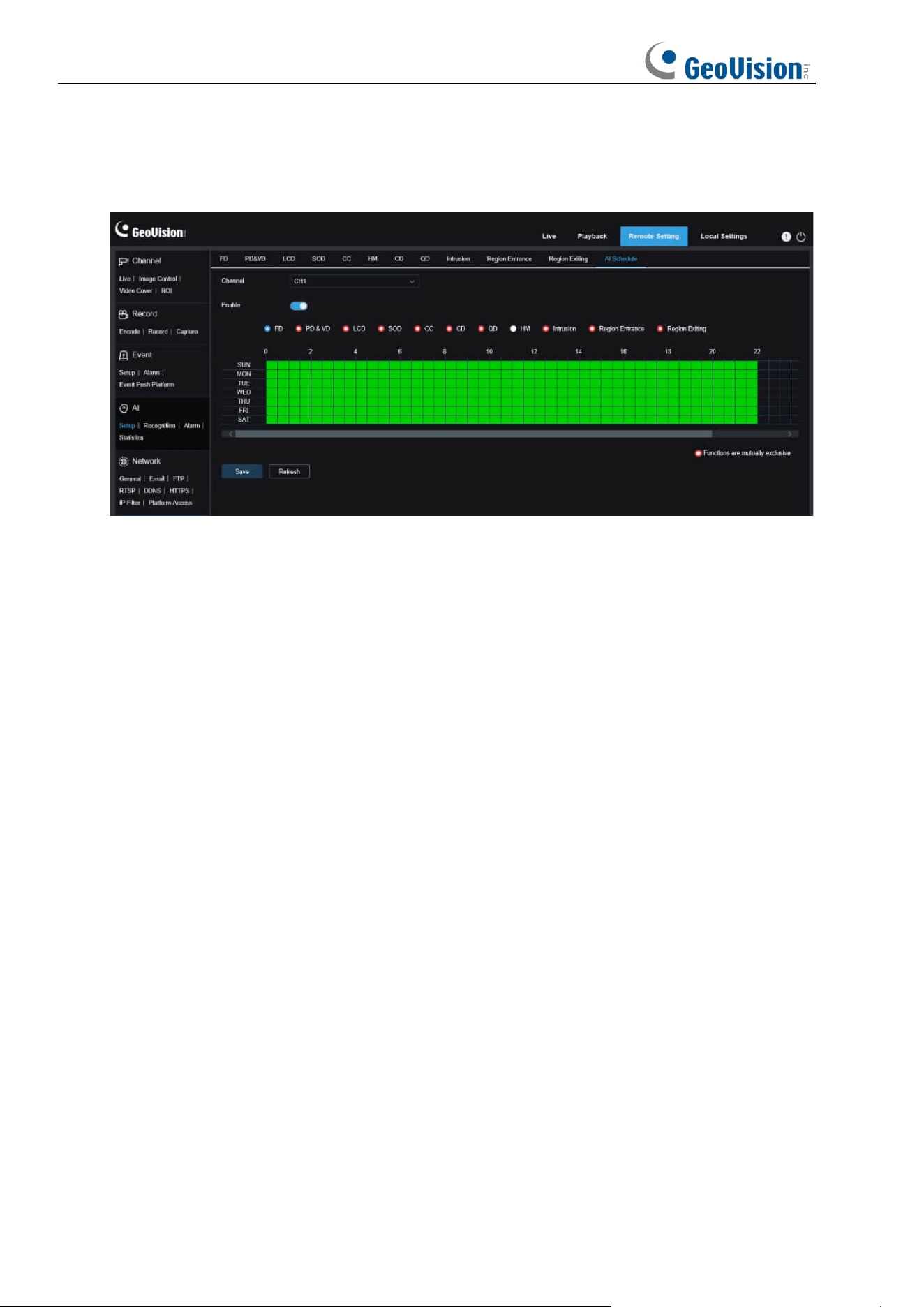
103
8.7.1.13 AI Schedule
AI schedule. You can set the AI enable schedule with this function. This function can be
enabled or disabled.
Channel: Users can select a channel and set parameters (only applicable to GV-RMS32810).
Enable: Used to turn on the schedule.
Functions are mutually exclusive: Functions that are mutually exclusive to the selected
functions.
Note:
• Functions that are mutually exclusive cannot be set at the same time. That is, two
mutually exclusive AI functions cannot be enabled at the same time. There will be
restrictions on this UI.
• After the AI schedule is enabled, all AI function switches for the channel can no longer
be manually enabled or disabled and are controlled by the schedule. However,
parameters such as sensitivity can be edited.
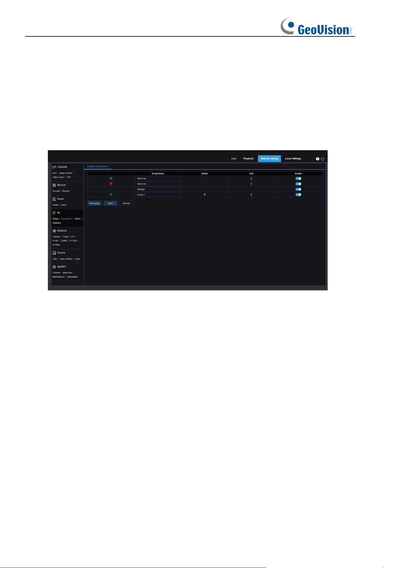
104
8.7.2 Recognition
8.7.2.1 Face Recognition
Face recognition function. The focus is to recognize the identity of a detection object and use
base data for comparison. The program establishes a database for face matching using the
database management function.
Note: Changes to the database take full effect after the system reloads data for a short period
of time.
Alarm Policy Display: This serves as a policy prompt only in the camera. Green indicates
the allow list, red indicates the block list, and colorless indicates the stranger group.
Group Name: Here you can edit, modify, and view the current group name. A group name will
be pushed together with an alarm.
Delete: Here you can delete a group. The first three group cannot be deleted.
Edit: Here you can open the image setting example for this group. For details, please
continue editing the content on the next image.
Enable: Used to turn on or off the face recognition function for data comparison between
groups.
Add Group: Allows you to add a new database group. Up to 16 database groups can be
added.
You can click the Edit icon to set the reference data for the corresponding group. The view is
shown in the figure below.
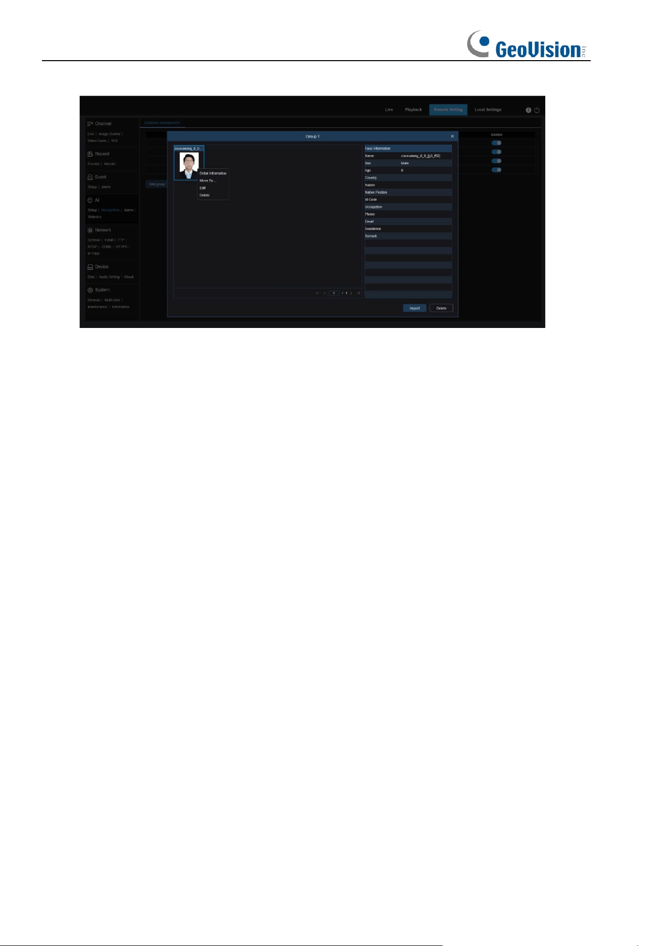
105
Added Image Display Area: Displays images that have been added to groups in the face
database.
Info: Displays the editing information of the selected image.
Detail Information: Right click event to check the information of the selected image.
Move To...: Right click event to move the selected image to other groups.
Edit: Right click event to open the editing interface of the selected image to edit the
information again.
Delete: Right click event to delete the selected image.
Import: You can add new face data in the current group and import local images or captured
images by the camera.
Delete: Used to delete face data in batches in the database. You can click this icon, select the
image to be deleted, and then click the Delete icon again to delete the image.
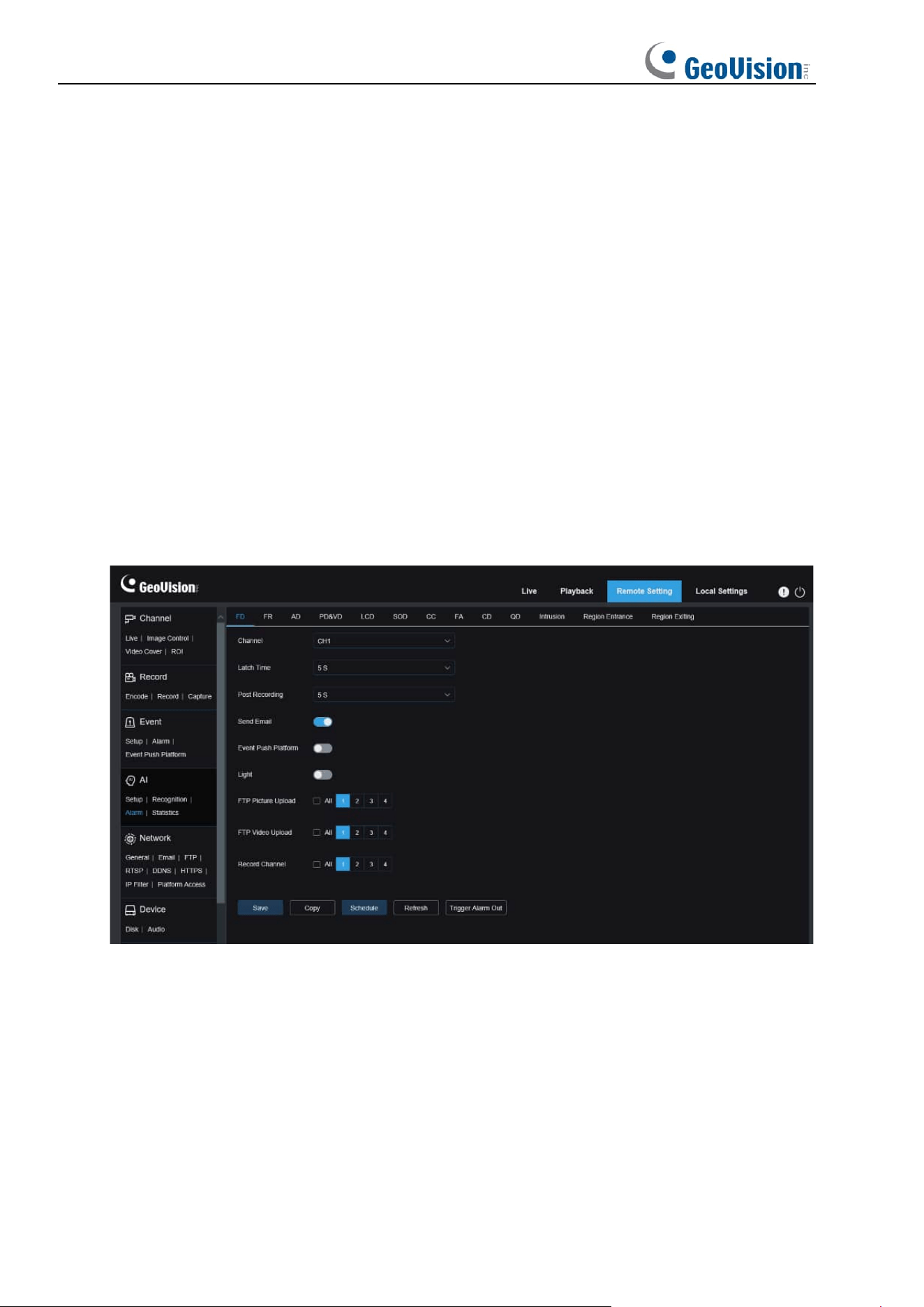
106
8.7.3 Alarm Setup
Alarm response to AI functions of the camera can be divided into three categories in the
implementation dimension:
Category I includes FD, AD, PD&VD, PID, LCD, SOD, CC, CD, QD, and RSD. Alarm
response will be generated directly if alarm conditions are met as determined by the camera.
Category II includes FR. The camera captures an alarm image and recognizes the face
feature value in the image, then compares it with the information in the database, and finally
generates an alarm response according to the alarm group setting.
Category III includes FA. Automatically search data at a specific time to generate alarm push
email.
8.7.3.1 FD, AD, PD&VD, PID, LCD, SOD, CC, CD, QD, RSD, Intrusion, Region Entrance /
Exiting
Alarm response will be generated directly if alarm conditions are met as determined by the
camera.
Channel: Users can select a channel and set parameters (only applicable to GV-RMS32810).
Alarm Type: This option is specific to AD alarms. Enable the face attribute recognition
function for AD alarms. An alarm will be generated to alert whether the detected object wears
a mask. There are three mode options.
Close: AD alarms are disabled.
NO Mask: An alarm is generated when the detected object is not wearing a mask.
Wear Mask: An alarm is generated when the detected object is wearing a mask.
Latch Time: Specifies the duration of an I/O alarm after the alarm is cleared.

107
Note: The camera must support the I/O feature and the working time is controlled by the
schedule.
Post Recording: Specifies the duration of recording after the alarm is cleared.
Note: The effective time is also controlled by the schedule.
Send Email: Specifies whether to send an email when an alarm is being triggered.
Note: The effective time is also controlled by the schedule.
Light: White light deterrence switch. When an alarm is triggered, the alarm response will be
made according to the Remote Setting-Event-Setup-Deterrence setting on the white light
deterrence page.
FTP Picture Upload: Specifies whether to send pictures to the associated FTP server when
an alarm is being triggered. If the alarm is continuously triggered, the pictures will be sent at
an interval of 10s until the alarm is cleared. For GV-RMS32810, you can select the desired
channel(s) or all channels.
Note: The effective time is also controlled by the schedule and the FTP server shall be
associated in advance.
FTP Video Upload: Specifies whether to send videos to the associated FTP server when an
alarm is being triggered. If the alarm is continuously triggered, the videos will be sent at an
interval of 10s until the alarm is cleared. For GV-RMS32810, you can select the desired
channel(s) or all channels.
Note: The effective time is also controlled by the schedule and the FTP server shall be
associated in advance.
Alarm Out: Specifies whether to enable Latch Time.
Enable Record: Specifies whether to enable Post Recording.
Record Channel: Specifies the channel to record when an alarm is triggered. For
GV-RMS32810, you can select the desired channel(s) or all channels.
Schedule: Used to configure the schedule of Send Email, Alarm Out, FTP Picture Upload,
FTP Video Upload, and Record for the current alarm. (Note: The white light deterrence feature
is available for some models.)
Event Push Platform: If this option is set to ON, this type of information will be pushed to the
client when an alarm is triggered.
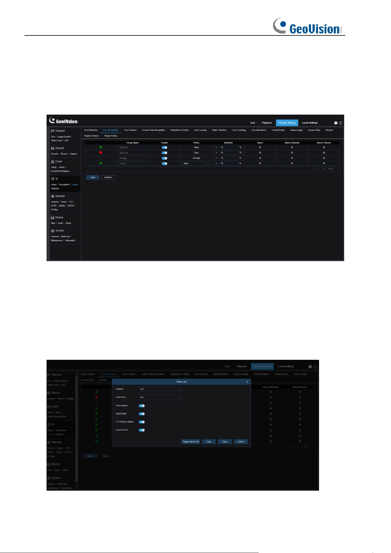
108
8.7.3.2 FR
Face recognition. The camera captures a face image and retrieve matching face data from
the database to obtain the group the object is in. Then, the camera generates an alarm by
calling out the alarm setting in this group. Changes to parameters take effect after the system
reloads data for a short period of time.
Group Name: Here you can edit, modify, and view the current group name. A group name will
be pushed together with an alarm in the live view.
Enable: Specifies whether to enable alarm response settings.
Policy: Alarm policy. The first three groups cannot be edited and other groups can be
customized as Allow or Deny.
Similarity: An alarm is triggered when the similarity exceeds the threshold during face
matching.
Alarm: Specifies whether to enable group alarm settings.
Alarm Schedule: Specifies the effective time of the Send Email, Alarm Out, and FTP Picture
Upload settings.
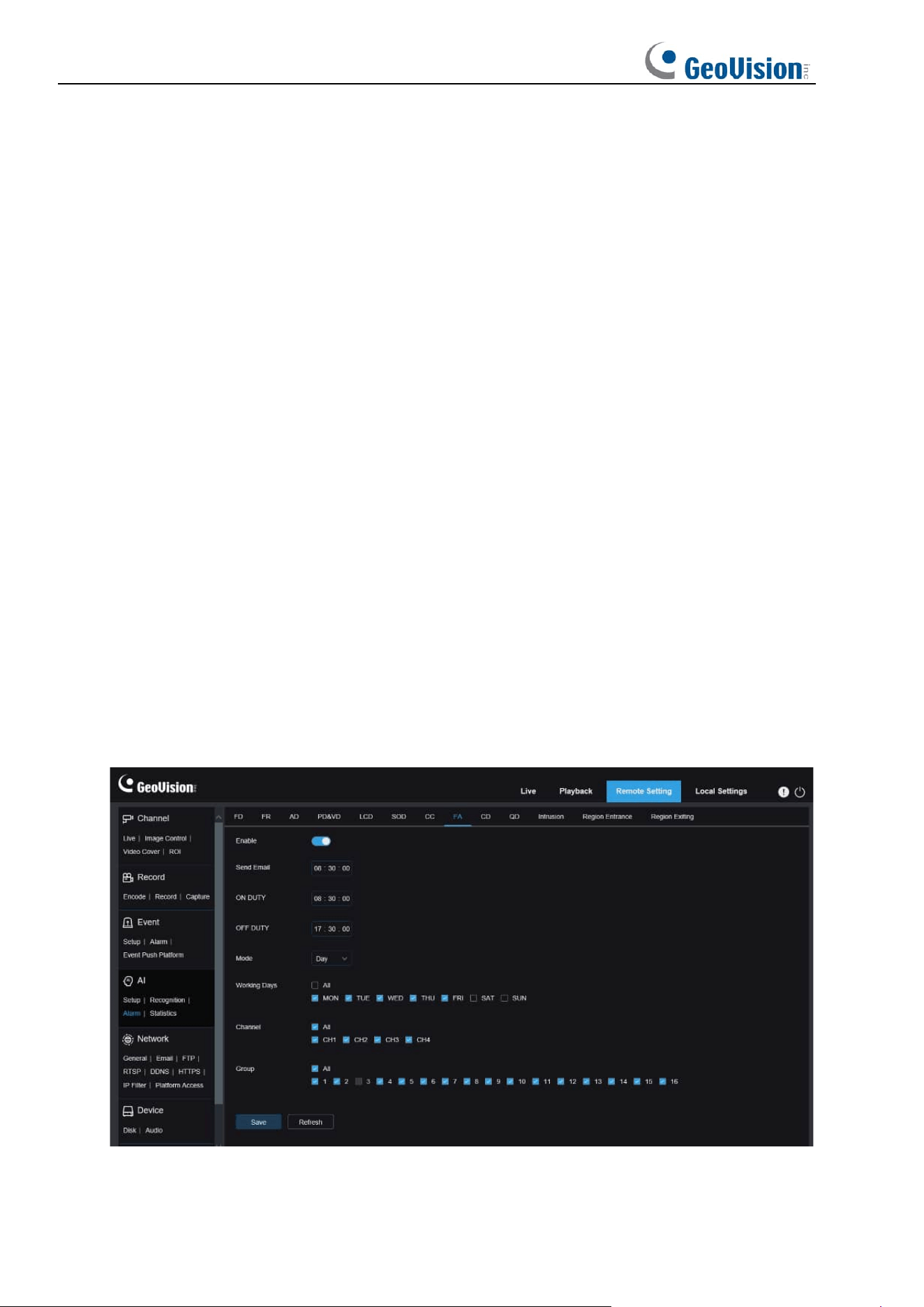
109
Latch Time: Specifies the duration of an I/O alarm after the camera captures the image and
successfully retrieves the matched image in the database.
Note: The camera must support the I/O feature and the working time is controlled by the
schedule.
Alarm Out Latch Time: Specifies whether to enable settings.
Save Picture: Specifies whether to save face images to the memory card.
This setting is not controlled by the Enable status.
Save the Background: Specifies whether to save face images to the memory card and at the
same time save background images.
This setting is not controlled by the Enable status.
Send Email: Specifies whether to send an email when faces in the group are recognized and
matched.
Note: The effective time is also controlled by the schedule.
FTP Picture Upload: Specifies whether to send pictures to the associated FTP server when
faces in the group are recognized and matched.
Note: The effective time is also controlled by the schedule and the FTP server shall be
associated in advance.
8.7.3.3 FA (Face Attendance)
The face attendance (FA) function is used to retrieve face matching status in different groups
(excluding stranger group) saved in the memory card in a specified period of time, and
generate attendance files according to capture records, and send these files to the associated
email address.
Enable: Used to turn on or off the automatic face attendance file generation function.

110
Send Email: Specifies the time to send face attendance status. The program will make
retrieval at a certain interval. When the retrieval time is greater than the set time, an
attendance record file is automatically generated and an email is sent.
Note: No email will be sent if no attendance record is available.
ON DUTY: Specifies the on-duty reference time to generate an attendance file.
OFF DUTY: Specifies the off-duty reference time to generate an attendance file.
Mode: Specifies the time to generate and send an attendance file. There are three mode
options.
Day: Allows you to send the attendance record file of the day before.
Week: For example, if it is set to Wednesday, the attendance information from last
Wednesday to this Tuesday will be sent on Wednesday.
Month: For example, if it is set to the 15th day, the attendance information from the 15th
day of the last month to the 14th day of this month will be sent on the 15th day of each
month.
Working days: Specifies the on-duty reference working days to generate an attendance file.
Channel: Specifies channels (only applicable to GV-RMS32810).
Group: Specifies the group subject to attendance check when an attendance file is
generated.
Note: This function is unavailable for the stranger group and grayed out for group 3 by default.
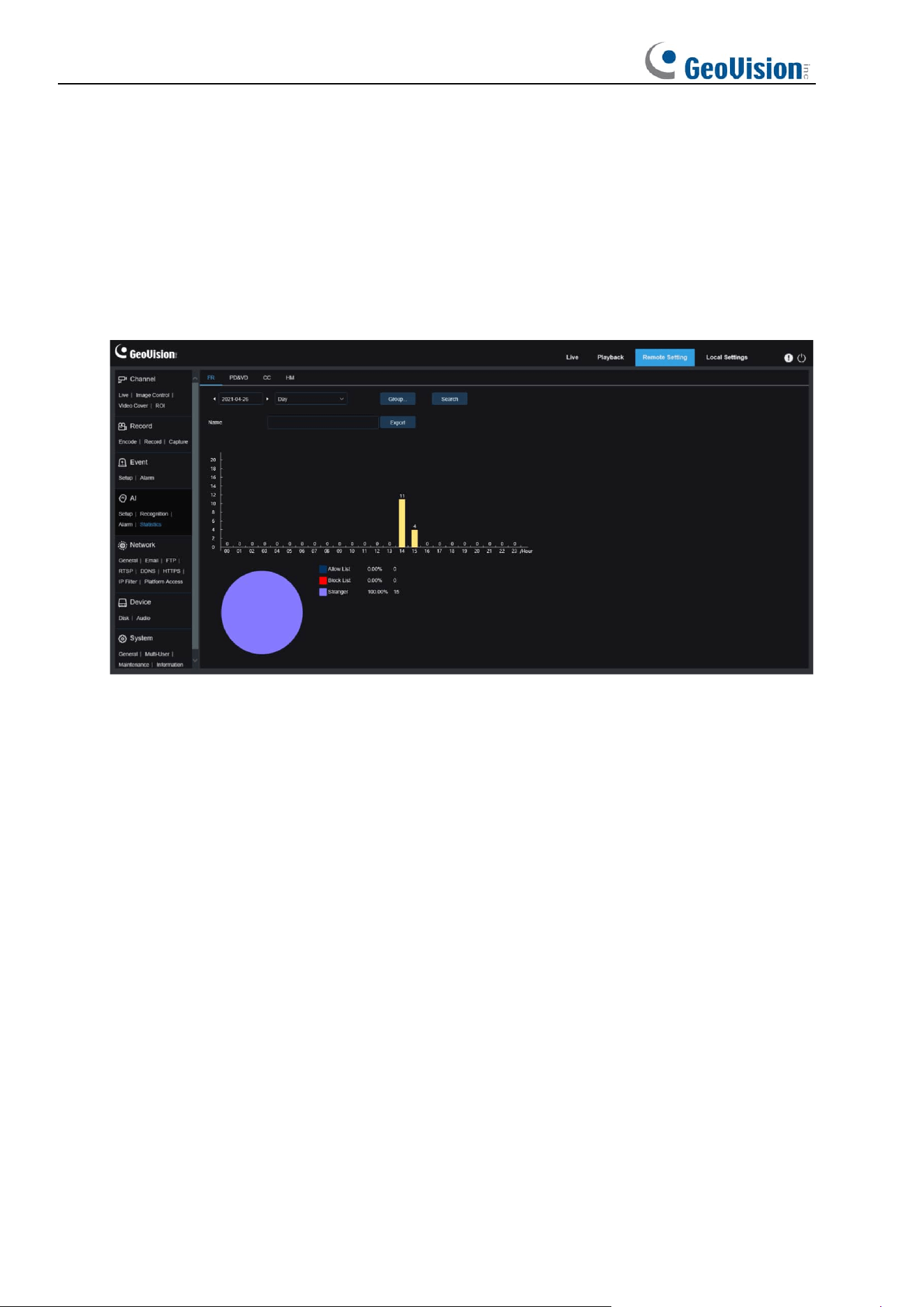
111
8.7.4 Statistics
AI-enabled statistical analysis function.
8.7.4.1 Face Detection
Face image statistical analysis function. This function allows you to retrieve face data
statistics stored in the memory card according to search settings. The screen is shown in the
figure below.
Time: Specifies the reference time for the Search Mode.
Search Mode: You can specify Day, Week, Month, Quarter, and Year as time range for data
retrieval.
Channel: Users can select a channel and set parameters (only applicable to GV-RMS32810).
Group: Specifies the group subject to retrieval when statistical data is being retrieved.
Search: Allows you to re-initiate data retrieval according to the current search settings.
Export: You need to give a name to an exported file. Export current search results to an Excel
file.
Display Area: Displays search results in a graph below.
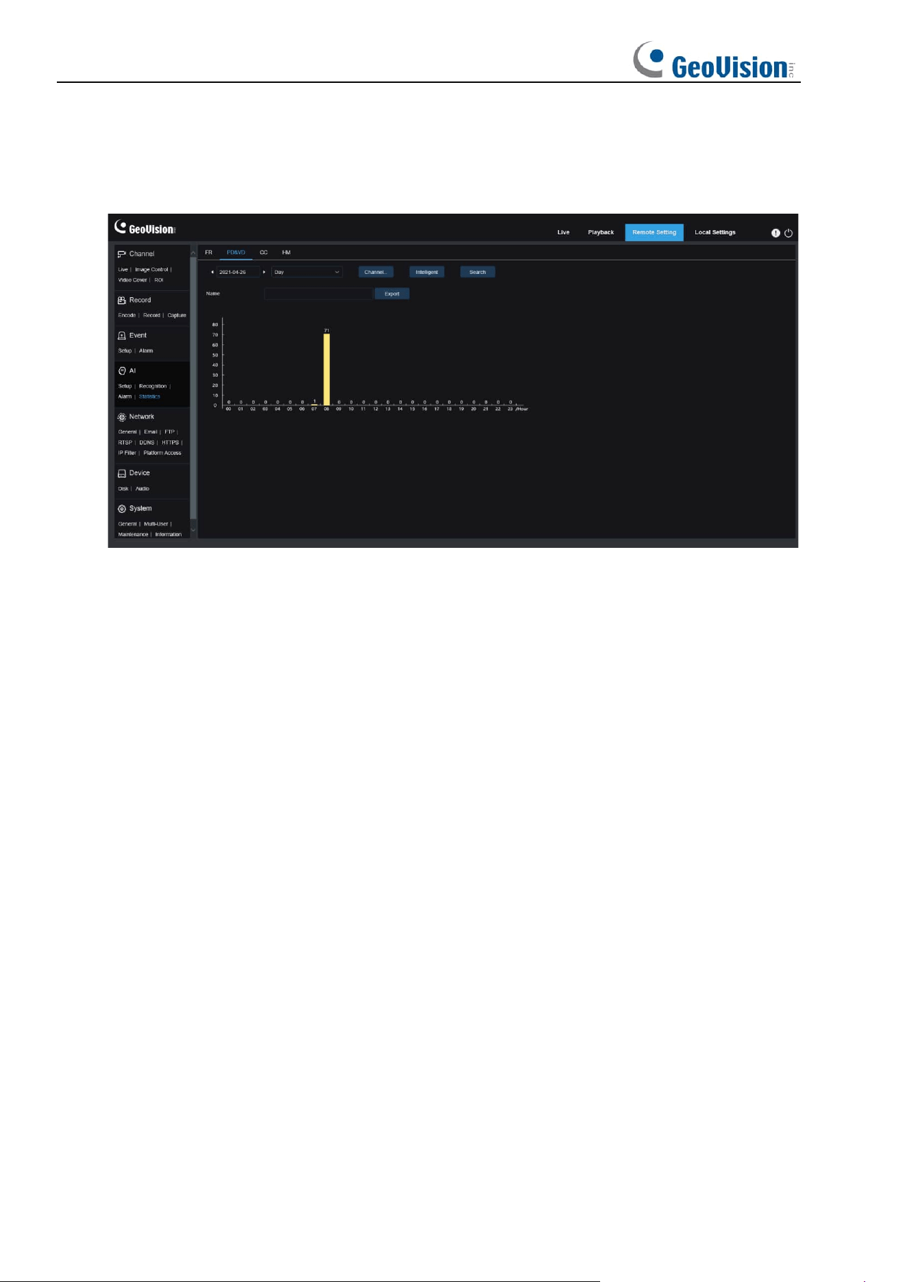
112
8.7.4.2 Human & Vehicle Detection
Human and vehicle statistics, including PD&VD, PID, and LCD alarms. The screen is shown
in the figure below.
Time: Specifies the reference time for the Search Mode.
Search Mode: You can specify Day, Week, Month, Quarter, and Year as time range for data
retrieval.
Channel: Users can select a channel and set parameters (only applicable to GV-RMS32810).
Intelligent: Allows you to perform search according to tag type of captured images.
Search: Allows you to re-initiate data retrieval according to the current search settings.
Export: You need to give a name to an exported file. Export current search results to an Excel
file.
Display Area: Displays search results in a graph.
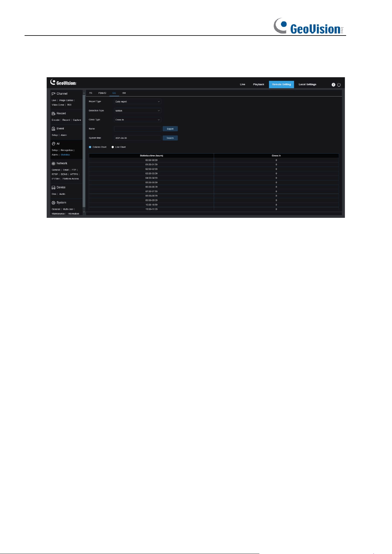
113
8.7.4.3 Cross Counting Statistics
Cross counting (CC) statistics. The screen is shown in the figure below.
Channel: Users can select a channel and set parameters (only applicable to GV-RMS32810).
Report Type: The options include Daily report, Weekly report, Monthly report, and Annual
report.
Detection Type: Used to set your desired alarm model. For example, you cannot retrieve
motion-triggered data if alarm models other than motion models are selected. There are four
model options including Motion, Pedestrian, Motor Vehicle, and Non-motorized Vehicle
corresponding to their function settings.
Cross Type: Allows you to search for data according to cross counting (CC) statistics. There
are two mode options, including Cross In and Cross Out.
Export: You need to give a name to an exported file. Export current search results to an Excel
file.
System time: Specifies the reference time for the selected report type.
Mode: Specifies whether to display graphs in the icon display area in a column or line chart.
Display Area: Displays search results in a graph.
Search: Used to search for data according to current settings.
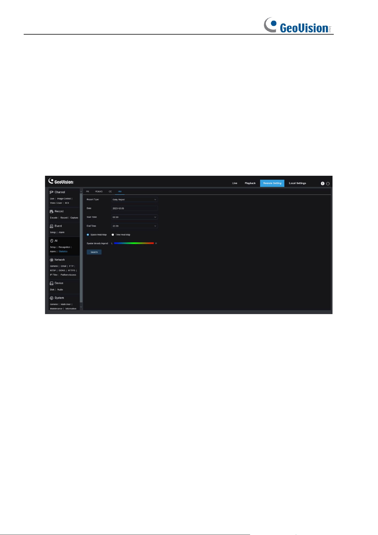
114
8.7.4.4 Heat Map Statistics
The heat map can intuitively present people distribution in temporal or spatial dimension.
• Space heat map: People activity degree in different areas in the view. Red indicates the
densest area, meaning the highest activity degree, and blue indicates the lowest dense
area.
• Time heat map: People activity degree in different times in the view. The Y-axis value is
the index calculated based on the number of people and the duration of stay. The higher
the value is, the higher the activity degree will be. It does not represent the number of
people.
The smart camera must be equipped with a memory card with free space in which heat map
information will be stored. The screen is shown in the figure below.
Channel: Users can select a channel and set parameters (only applicable to GV-RMS32810).
Report Type: The options include Daily report, Weekly report, Monthly report, and Annual
report.
Date: Specifies the reference date for data search.
Start Time: This option is available only for Daily report and used to set the hour to start
searching.
End Time: This option is available only for Daily report and used to set the hour to end
searching.
Mode: Specifies the data display mode. There are two mode options including graph and
table.
Display Area: Displays the change frequency of monitored areas as a graph, and displays
the change frequency of monitored areas in different time periods as a table.
Search: Used to search for data according to current settings.
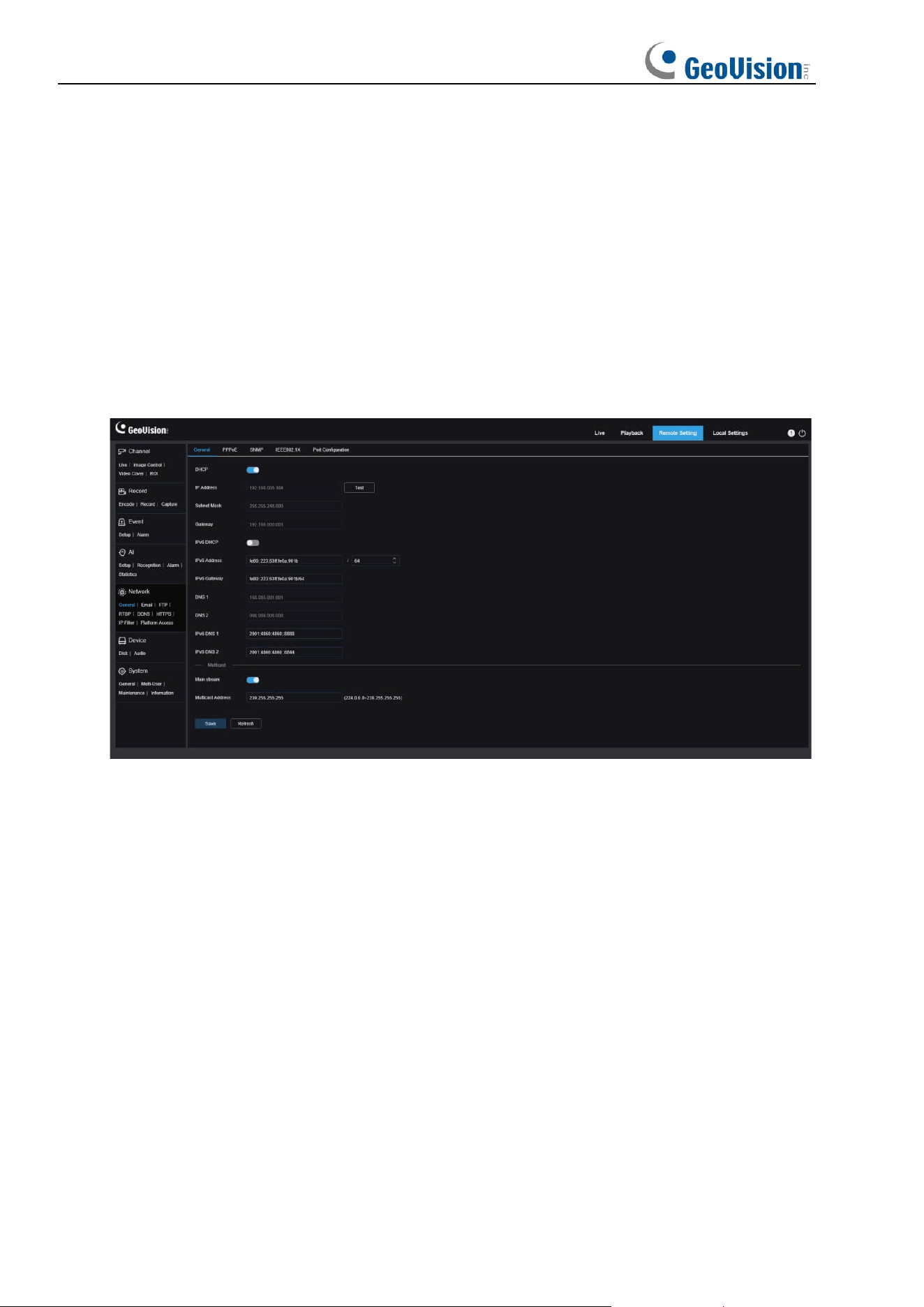
115
8.8 Network Settings
This menu allows you to configure network parameters, such as, PPPoE, DHCP, and SNMP,
of which DHCP is the most common. In most cases, the network type is DHCP unless the
static IP address is set manually. If you need an authenticated username and password to
connect to the network, select PPPoE.
8.8.1 Basic Settings
8.8.1.1 General
To connect to a router that allows DHCP, check the DHCP box. The router will automatically
assign all network parameters to the device. You can also choose to manually set the
following parameters for the network:
IP Address
: The IP address is the identifier of IPC on the network. It consists of four numbers
between 0 and 255 separated by periods. for example, "192.168.001.100".
Subnet Mask:
A subnet mask is a network parameter that defines the range of IP addresses
that can be used in the network. If the IP address is likened to the street you live on, then the
subnet mask is the community. A subnet address also consists of four numbers separated by
periods, for example, "255.255.000.000".
Gateway:
This address allows IPC to access the network. The format of a gateway address is
the same as that of an IP address, for example, "192.168.001.001".
IPv6 Address:
The IPv6 address is the identifier of IPC on the network. It consists of eight
numbers between 0 and FFFF, separated by colons, for example,
"ABCD:EF01:2345:6789:ABCD:EF01:2345:6789”.
DNS1/DNS2: DNS1 is the active DNS server and DNS2 is the standby DNS server. Usually
you just need to enter the DNS1 server address.
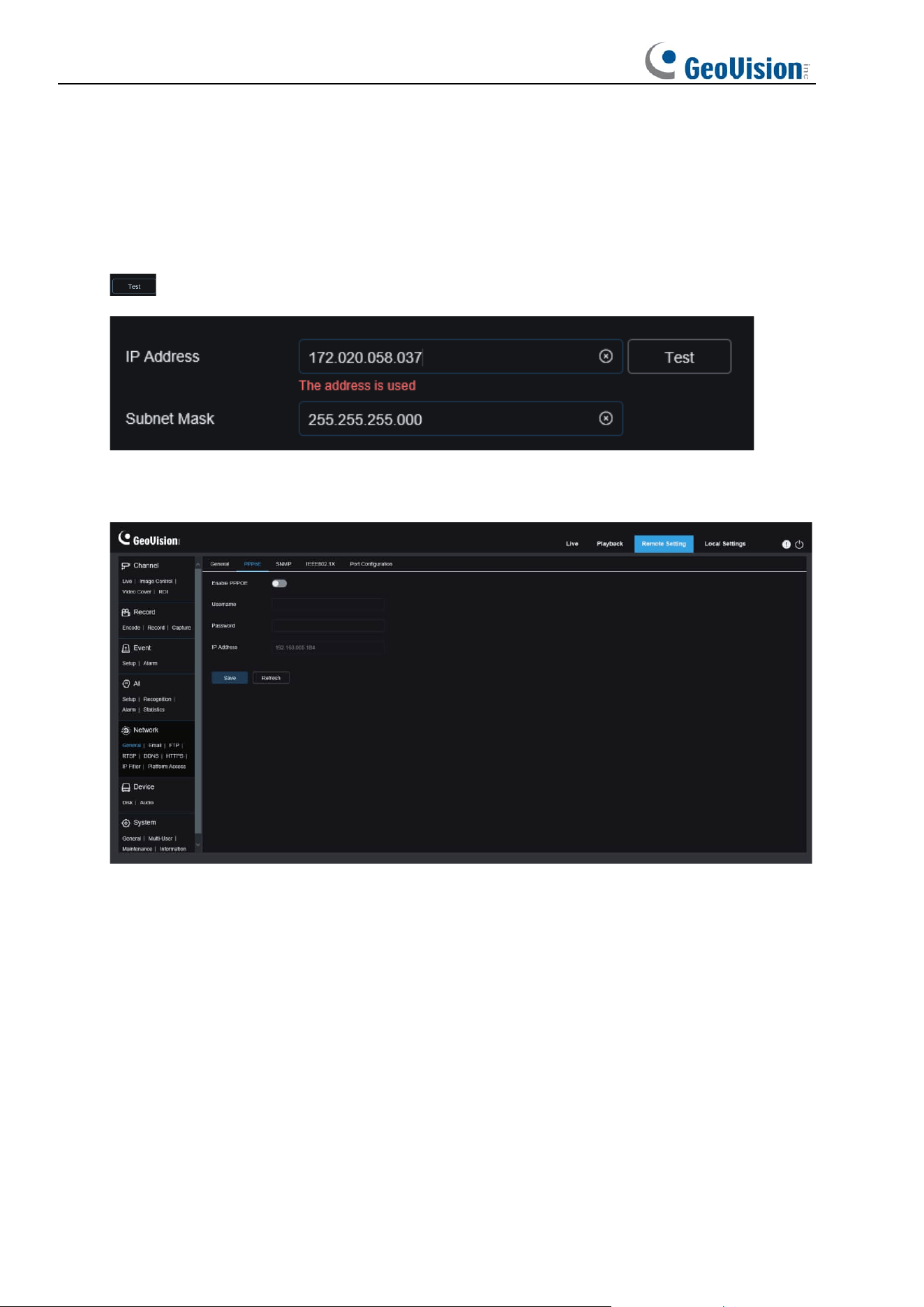
116
Main Stream: If this option is enabled, the main stream can be used for multicast.
Muticast Address: Specifies a multicast address. A third-party player can request the
camera to send a multicast media stream through the RTSP protocol.
If the IPC is capable of warning you of repeated IP addresses in the same network segment,
when IP addresses are repeatedly used, the following message will pop up when you click the
icon:
8.8.1.2 PPPoE
This is an advanced protocol that allows the IPC to connect to the network more easily via
DSL modems.
Turn on the "Enable PPPoE" box and then enter the username and password of PPPoE.
Click the "Apply" to save data. The system will restart to take PPPoE settings into effect.
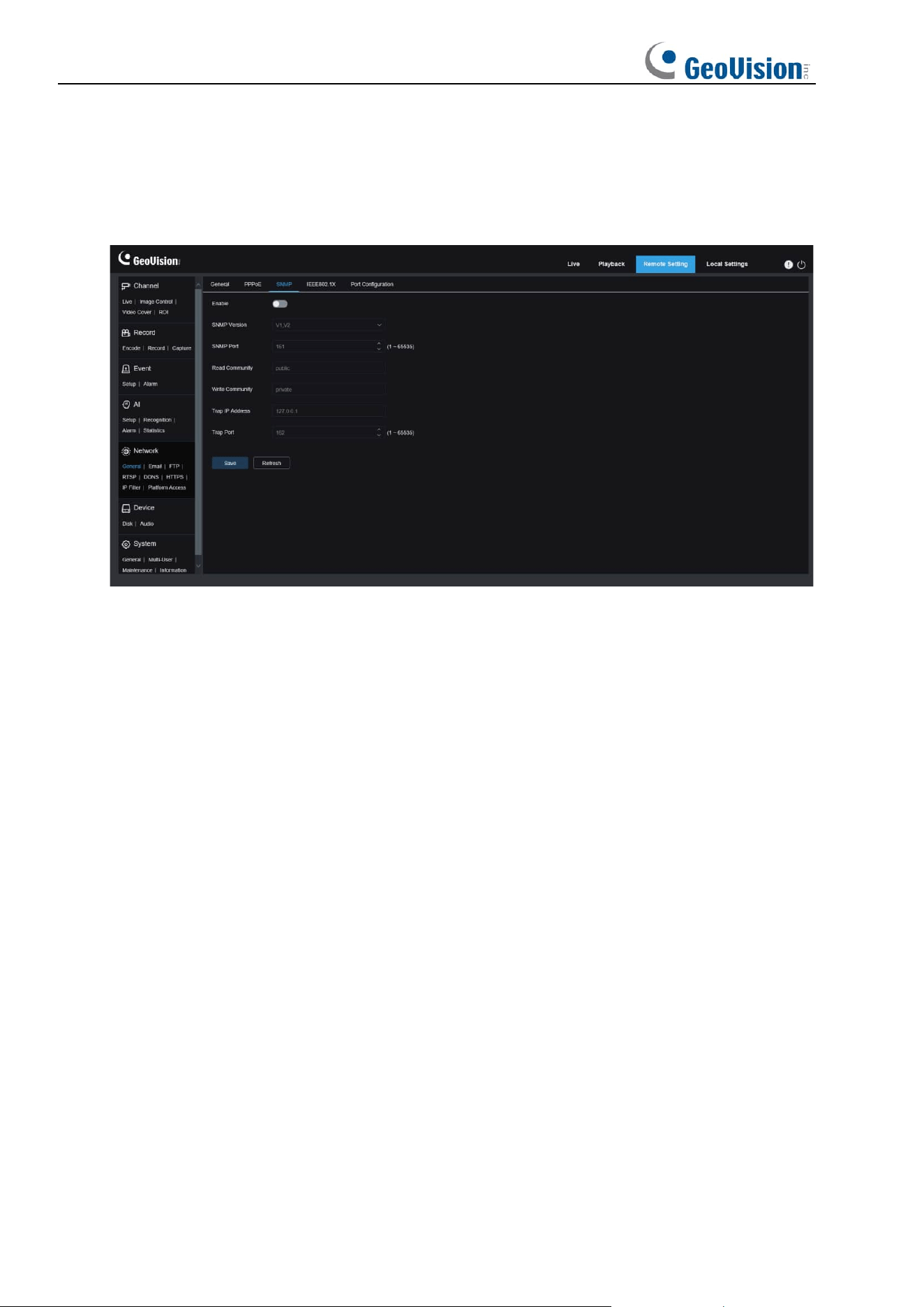
117
8.8.1.3 SNMP
Simple Network Management Protocol (SNMP) is a standard application-layer protocol that is
designed to manage nodes such as servers, workstations, routers, switches, and HUBS over
IP networks.
Enable: Used to turn on or off SNMP.
SNMP Version: Specifies the version of the SNMP server. The options include V1, V2 and V1,
V2, and V3.
SNMP Port: Specifies the port number of the SNMP server.
Read Community: Specifies the Read Community value of the SNMP server.
Write Community: Specifies the Write Community value of the SNMP server.
Trap IP Address: Specifies the Trap IP address of the SNMP server.
Trap Port: Specifies the Trap port number of the SNMP server.
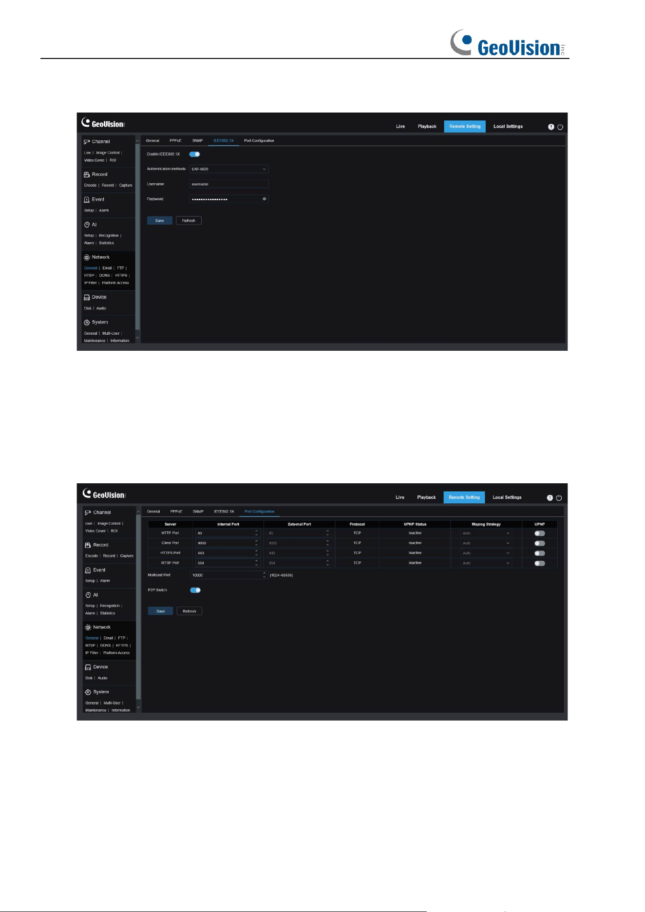
118
8.8.1.4 IEEE802.1X
Enable: Used to turn on or off IEEE802.1X.
Authentication methods: Select the desired authentication method.
Username / Password: The username and password must be the same with the username
and password applied for and registers in the authentication server.
8.8.1.5 Port Settings
HTTP Port
: This is the port you use to remotely log in to the IPC (for example, using a web
client). If port 80 is already used by other applications, change the port number.
Client Port
: This is the port through which the IPC will send messages (for example, using a
mobile application). If default port 9000 is already used by other applications, change the port
number.
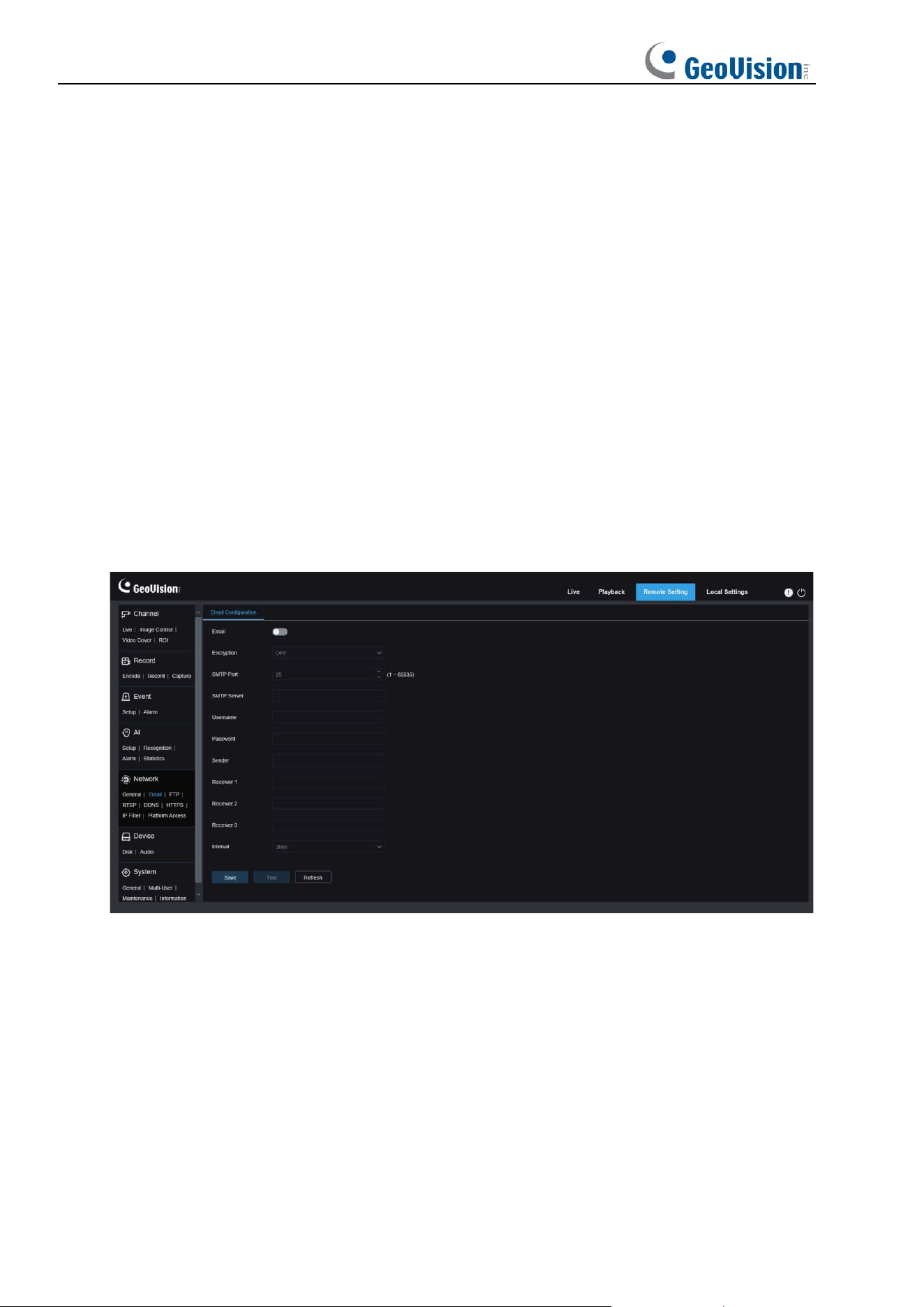
119
RTSP Port:
The default port number is 554. If it is already used by other applications, change
the port number.
HTTPS
: It is an HTTP channel aiming for security. On the basis of HTTP, transmission
encryption and identity authentication are used to ensure the security of transmission.
UPNP
: To remotely log in to the device from a web Client, perform port forwarding on the
router. Enable this option if your router supports UPnP. In this case, you do not have to
manually configure port forwarding on the router. If your router does not support UPnP, make
sure that port forwarding is done manually on your router.
Multicast port:
Specifies a multicast port.
P2P Switch:
P2P is ineffective if this switch is turned off.
8.8.2 Email Setting
This menu allows you to configure email settings. Complete these settings if you want to
receive system notifications via email when an alarm is triggered and your hard drive is full.
Email
: Used to turn on or off email.
Encryption
: Enable this option if your email server requires SSL or TLS authentication. Set it
to Automatic if you are not sure.
SMTP Port
: Specifies the SMTP port number of the email server.
SMTP Server:
Specifies the SMTP server address.
Username
: Specifies your email address.
Password
: Specifies your email password.
Receiver 1~3
: Specifies the email address from which you want to receive event notifications
from the IPC.
Interval
: Specifies the interval between notification emails on the IPC.
120
To ensure that all settings are correct, click "
Test
". The system will send an email to your
inbox. If you receive a test email, the configuration parameters are correct.
8.8.3 FTP Server Settings
This menu enables you to enable the FTP server, through which you can view pictures and
videos uploaded from the IPC to your FTP server.
FTP Enable
: You can click this icon to enable the FTP feature.
Server
: Specifies the IP address or domain name of your FTP server.
Port
: Specifies the port number of your FTP server.
Username/ Password
: Specifies the username and password of your FTP server.
Transfer images:
When this option is turned on, alarm images will be uploaded to the FTP
server. Otherwise, only alarm texts will be uploaded.
Transfer Videos:
When this option is turned on, alarm videos will be uploaded to the FTP
server.
Note:
To play the video uploaded via FTP server, make sure to use the R Series Video
Player.
121
8.8.4 RTSP Settings
Real Time Streaming Protocol (RTSP), RFC2326, is an application layer protocol in the
TCP/IP protocol architecture. This protocol defines how one-to-many applications can
efficiently transfer multimedia data over IP networks. You can view real-time images using a
video player.
RTSP Enable: Used to turn on or off the RTSP. This protocol is available only when it is
turned on.
Anonymous Login: Allows you to log in as an anonymous user. Authentication is not
required for using this protocol if this option is turned on.

122
8.8.5 Dynamic Domain Name Settings (DDNS)
This menu allows you to configure DDNS settings. DDNS provides a static address to simplify
remote connection to the IPC. To use DDNS, you first need to sign up an account on the
webpage of the DDNS service provider.
DDNS
: Used to turn on or off DDNS.
Server
: Specifies your preferred DDNS server (DDNS_3322, DYNDNS, NO_IP, or
GEO_DDNS).
User/Password
: Specifies the username and password obtained when you create an
account on the webpage of the DDNS service provider.
Enter all parameters and then click "Test" to test DDNS settings. If the test result is
"Unreachable or DNS error", check whether the network works normally or the DDNS
information is correct.
123
8.8.6 HTTPS Settings
This menu allows you to set HTTPS. You can connect your device over HTTPS.
Certificate Type: There are two options, including default and custom. The Custom option
allows you to connect devices using your own certificate.
Certificate: Select a custom certificate when the Custom option is selected.
Key: Select a custom key file when the Custom option is selected.
8.8.7 IP Filter
The IP filter can be used to set the allow list and block list of devices to be connected.
Enable: Used to turn on or off the IP filter. You can choose to enable the block list or allow list
if this option is turned on.
124
Restricted Type: Used to select the list to be set (block list or allow list).
Start Address: Specifies the start address.
End Address: Specifies the end address.
8.8.8 Platform Access
8.8.8.1 RTMP Settings
Enable: Used to turn on or off the RTMP function.
Server Address: Enter the server address allocated by the third-party server.
Stream Type: Select the desired stream.
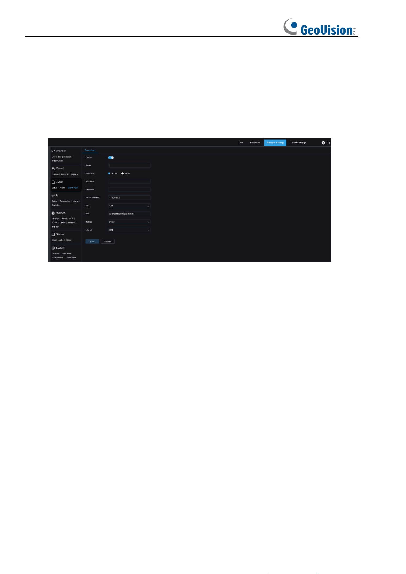
125
8.8.8.2 HTTP / UDP Event Push
Event push can be implemented in two modes: HTTP push mode and UDP push mode. HTTP
push mode provides POST method and GET method. UDP push mode provides unicast,
multicast, and broadcast methods. (Note: Only some models support the event push
function.)
HTTP Push
Enable: Used to enable or disable the event push function.
Name: Used to set the channel name.
Push Way: Used to set the push mode. Both HTTP push mode and UDP push mode are
supported. You can select HTTP or UDP as required.
Username: Used to set the username. It can be set to NULL if there is not any.
Password: Used to set the password. It can be set to NULL if there is not any.
Server Address: Used to set the server address.
Port: Used to set the server port. (port number range: 1–65535.)
URL: Used to set the server API. It can be set to NULL if there is not any.
Method: Used to set the HTTP push method. Both POST and GET methods are supported.
Only the HTTP-POST method supports image push. Other methods push notifications only.
The alarm type of image push is the same as that in the alarm column of live view on the Web
client.
Interval: Used to set the keep-alive interval. The keep-alive mechanism ensures that a
notification is periodically pushed to the client in accordance with the preset time while normal
alarm push is not affected. There is no keep-alive mechanism in UDP mode.
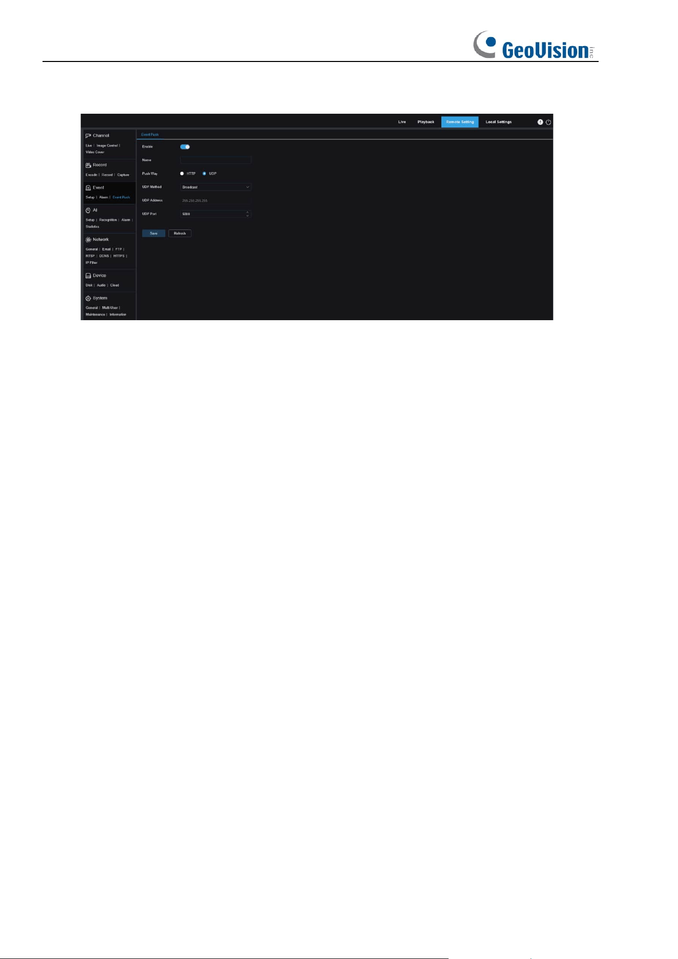
126
UDP Push
Enable: Used to enable or disable the event push function.
Name: Used to set the channel name.
Push Way: Used to set the push mode. Both HTTP push mode and UDP push mode are
supported. You can select HTTP or UDP as required.
UDP Method: Used to set the UDP push method. There are three options: Unicast,
Multicast, and Broadcast.
Unicast: Enter the IP address and port number of the client UDP server for receiving
push notifications. The notifications can be received by this address only.
Multicast: Multiple clients in the same network segment of which the UDP servers use
the same UDP address and port number can receive notifications. Other UDP addresses
cannot receive notifications.
Broadcast: All UDP servers in the same network segment can receive notifications.
UDP Address: Used to set the UDP server address.
UDP Port: Used to set the UDP server port. (port number range: 1–65535)
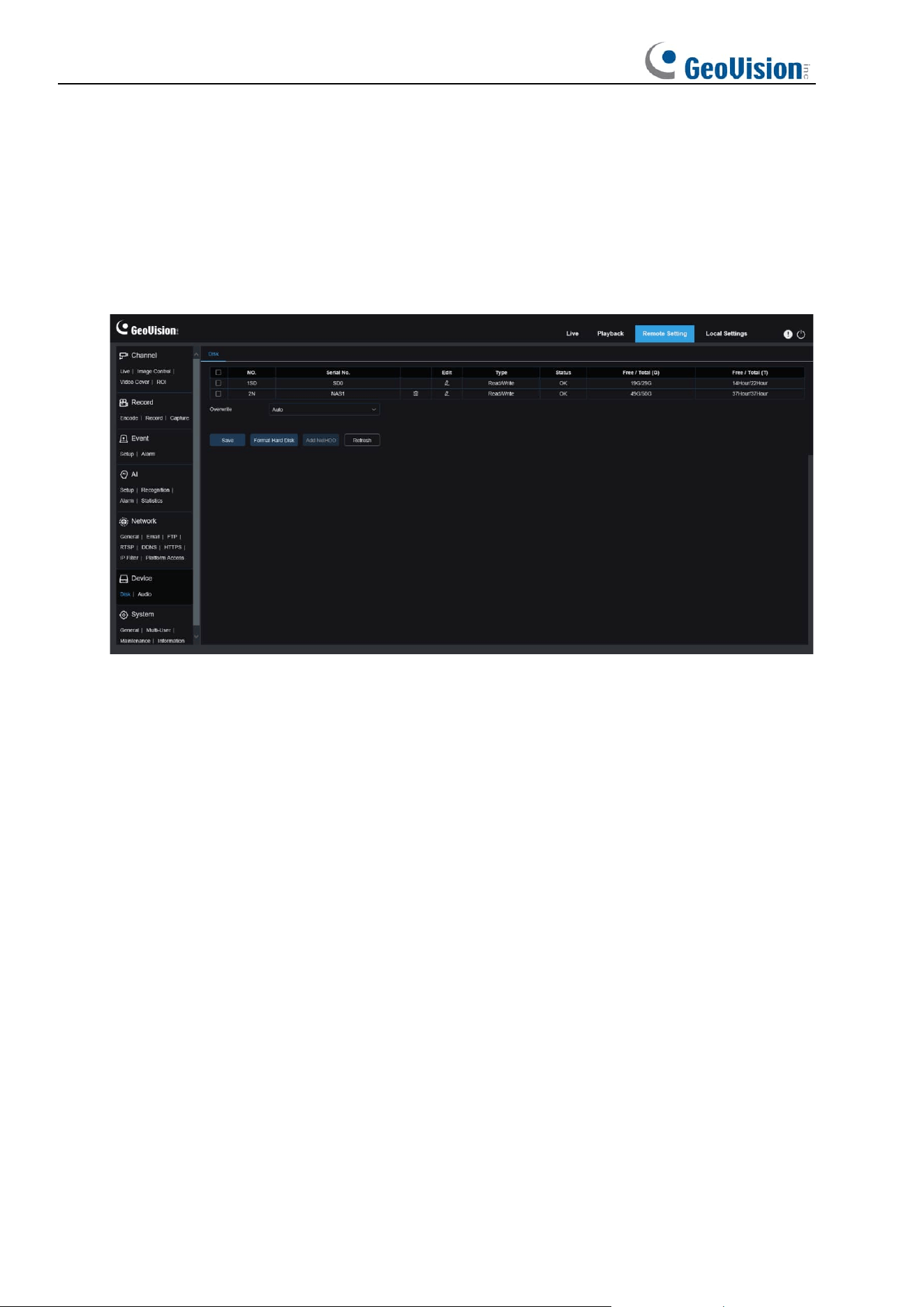
127
8.9 Device Management
8.9.1 Disk Management
This menu allows you to check and configure the internal SD Card. Formatting is required
only for initial access and when a new SD Card is used.
Format Hard Disk
: Select the SD Card to be formatted, and then click Format SD Card. To
start formatting, enter your username and password and then click OK.
Overwrite: Use this option to overwrite old records in the SD Card when the SD Card is full. If
Auto is selected, the oldest data will be automatically overwritten when the SD Card is full.
Select OFF if you do not want to overwrite any old videos. If this function is disabled, check
the status of the SD Card periodically to ensure that the SD Card is not full.
ADD NetHDD
: This function allows you to add a network HDD. After a network HDD (NAS) is
configured, you can connect the NAS to the Internet to record channel videos or capture
images. The AI face database can only be stored in the HDD.
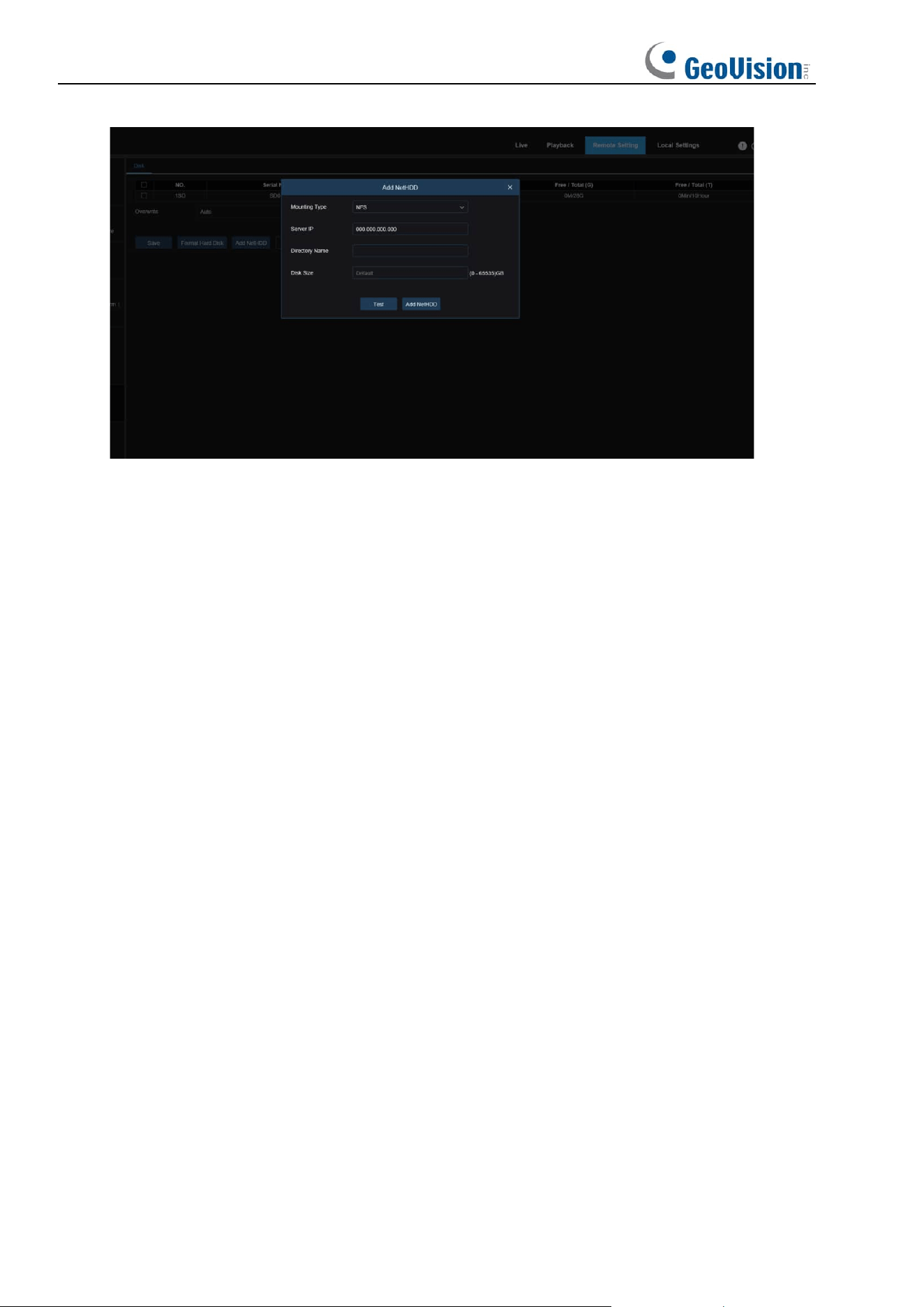
128
Mounting type
: There are two options, including NFS and SMB/CIFS. Among them, NFS
does not need username and password, but SMB/CIFS needs.
User Name
: Specifies the username of NAS (unavailable in NFS mode).
Password
: Specifies the password of NAS (unavailable in NFS mode).
Server IP
: Specifies the IP address of NAS.
Directory Name
: Specifies the folder where you want to store data in the NAS.
Disk Size
: Specifies the size of the network HDD.
Test
: Used to test the connectivity of NAS.
Add NetHDD
: You can click this option to add NAS.
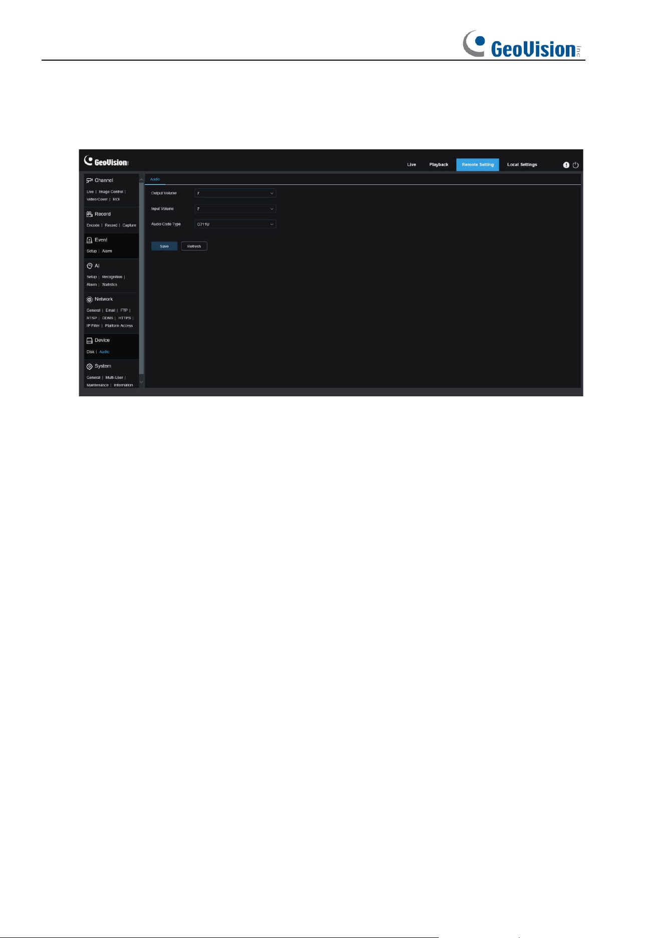
129
8.9.2 Audio Management
This menu is used to set the volume of your device.
Enable Audio: Used to enable or disable audio.
Output Volume: Specifies the volume of output audio.
Input Volume: Specifies the volume of input audio.
Audio Code Type: Specifies the audio decoding type. There are two options, including
G711A and G711U.
8.10 System Settings
Here you can change system information such as date and time and regions, and change the
password and permissions.
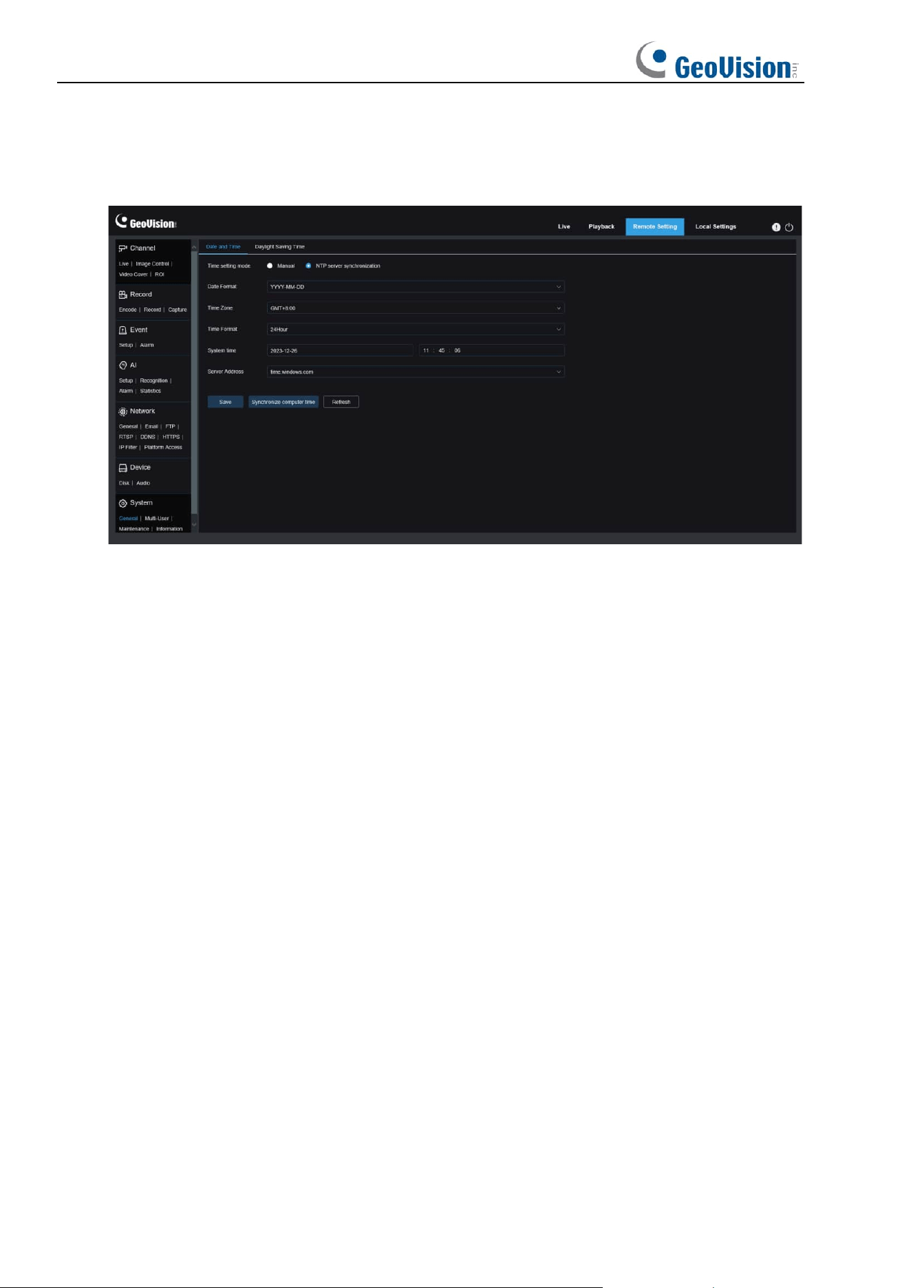
130
8.10.1 General
8.10.1.1 Date and Time
Time settings mode:
There are two options including Static and NTP server synchronization.
When Static is selected, you have to set the time manually. When NTP server synchronization
is selected, the time will be synchronized to the network time.
Date Format:
Specifies the date format.
Time Zone
: Specifies the time zone associated with your region or city.
Time Format
: Specifies your preferred time format.
System Time:
You can click the box to change the date and time.
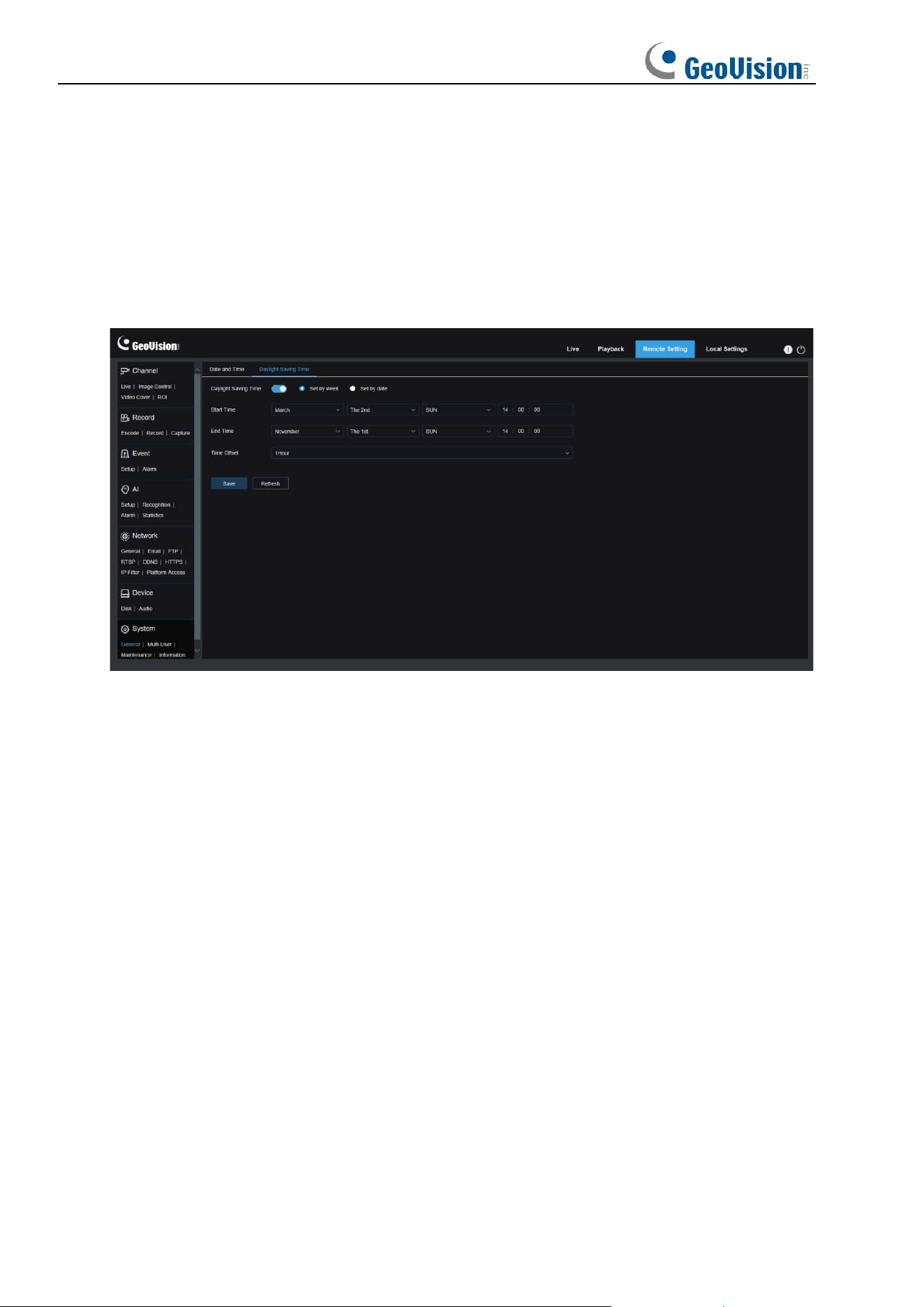
131
Synchronize computer time:
Here you can synchronize the time to the computer time.
You cannot set the time manually if NTP server synchronization is selected.
Sever Address:
Specifies the automatic time synchronization website.
8.10.1.2 Daylight Saving Time
The Daylight Saving Time (DST) function enables you to choose when to add daylight saving
time to a specific time zone or region.
Daylight Saving Time
: Turn on this option if DST is used in your time zone.
Set by week:
Specifies the month, weekday, and time when daylight saving time begins and
ends, for example, 2AM on the first Sunday of a month.
Set by date:
Specifies the date and time when daylight saving time begins and ends.
Start Time / End Time
: Specifies the start time and end time of daylight saving time.
Time Offset
: Specifies the time that daylight saving time adds to your time zone. This is the
difference between Universal Time Coordinated (UTC) and your local time.
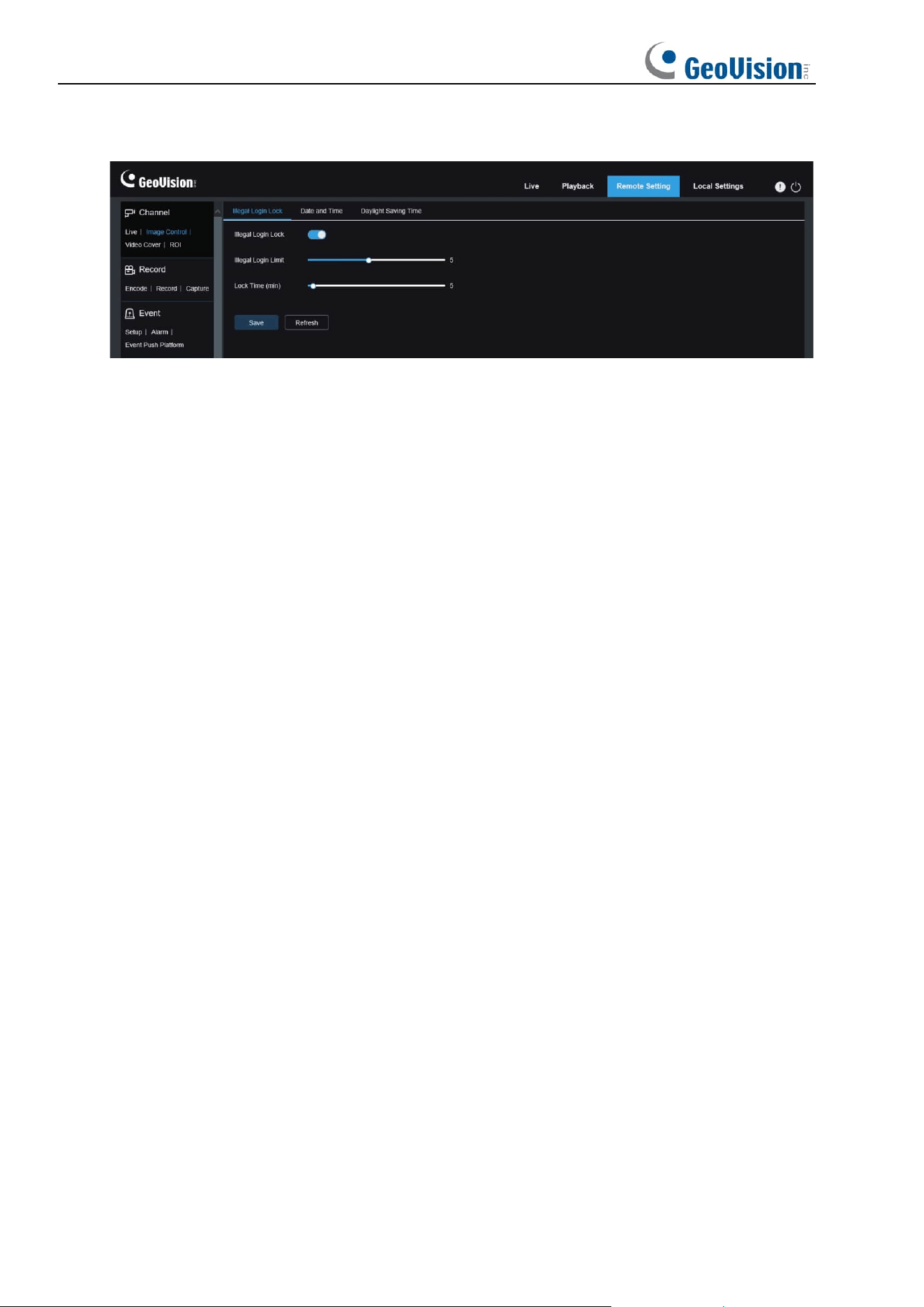
132
8.10.1.3 Illegal Login Lock
Enable Illegal Loging Lock
: Enable the illegal login lock for the camera to apply an account
lockout.
Illegal Login Limit / Lock Time (min):
Specify the Lock Time to activate the lockout when
reaching the set number of failed login attempts and for the lockout duration.
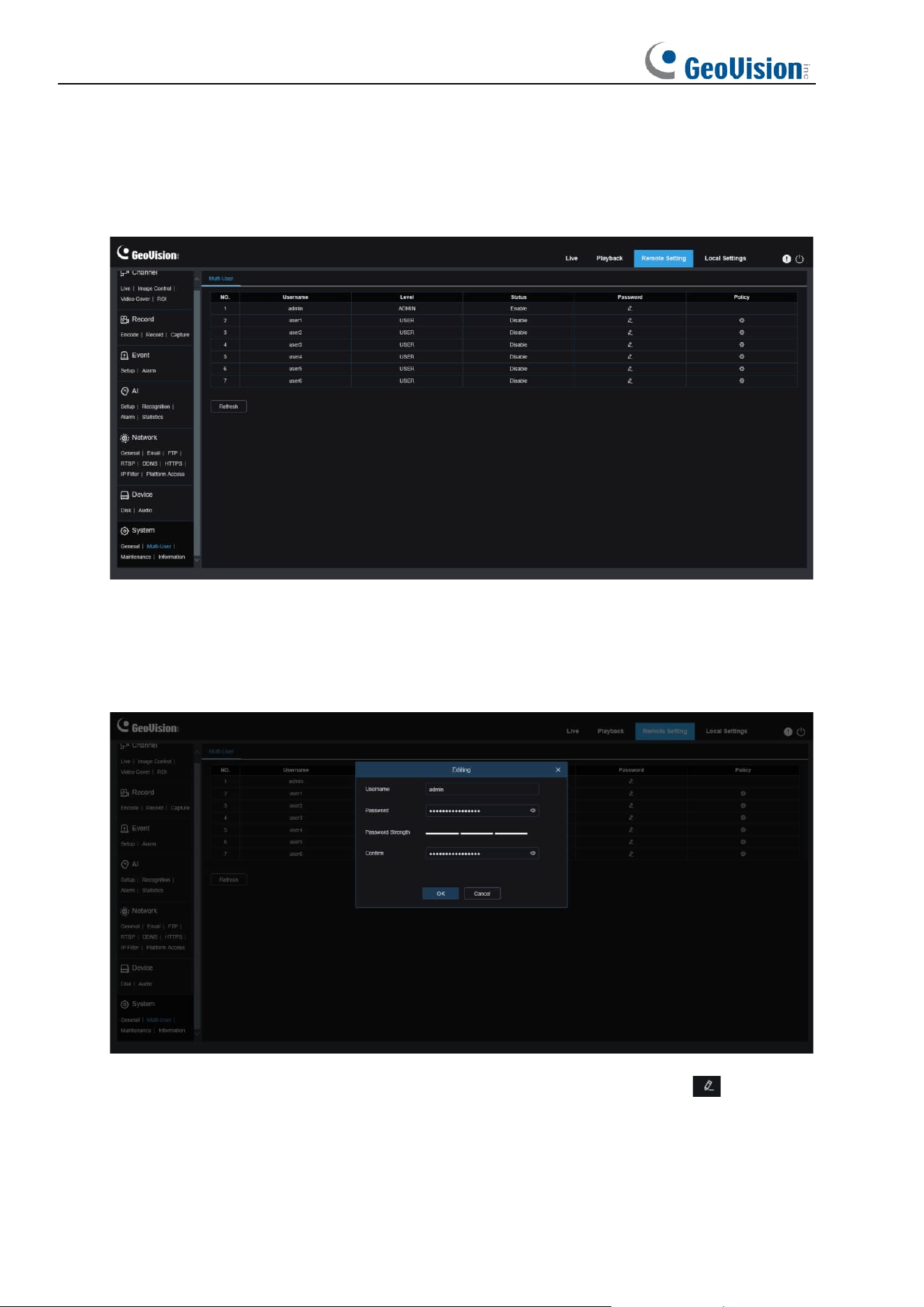
133
8.10.2 Multi-user Management
This menu allows you to configure username, password, and permissions.
The system supports user types as follows:
ADMIN - System Administrator
: A system administrator can fully configure the system and
can change administrator and user passwords as well as enable/disable password protection.
USER - Normal User: A normal user can only access the preview, search, playback and other
appropriate functions. You can set multiple users with different system access permissions.
To change an administrator or user password, click the "Edit Password" icon . The
password must be at least 8 characters long and a combination of numbers, letters, and
symbols. Enter the new password again for confirmation. Save the new password. You will be
asked to enter the old password for authentication.
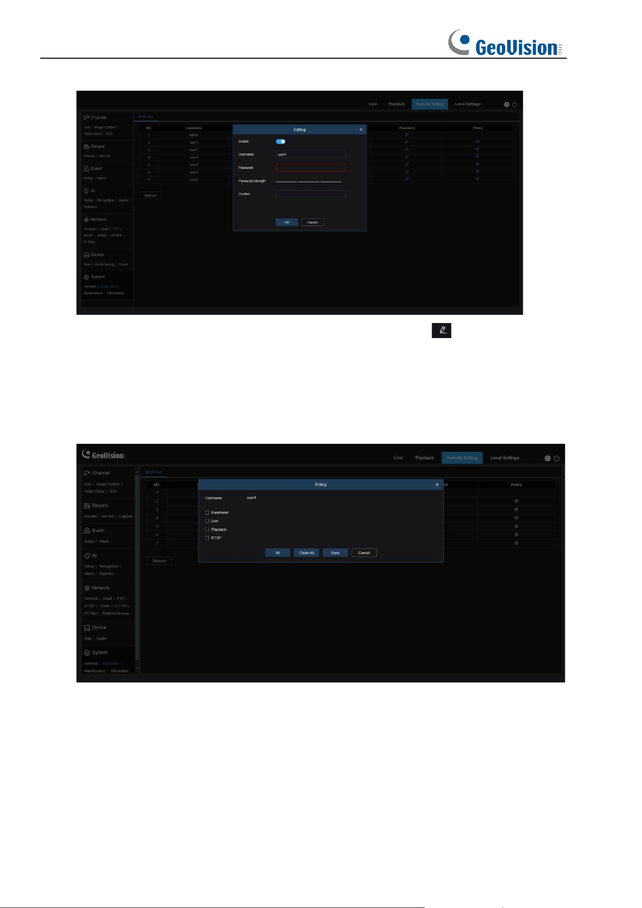
134
1. Select one of inactive users and click the "Edit Password" icon .
2. Turn on "
Enable
" to enable users.
3. Click "
Username
" to edit the username.
4. Click the field next to
Password
to enter your password.
5. Click the field next to
Confirm
to enter your confirm password.
Click Save. You will have to enter the administrator password for authentication.
Set user permissions and check the boxes corresponding to the functions. Click All to check
all boxes. Click Clear All to clear all boxes.
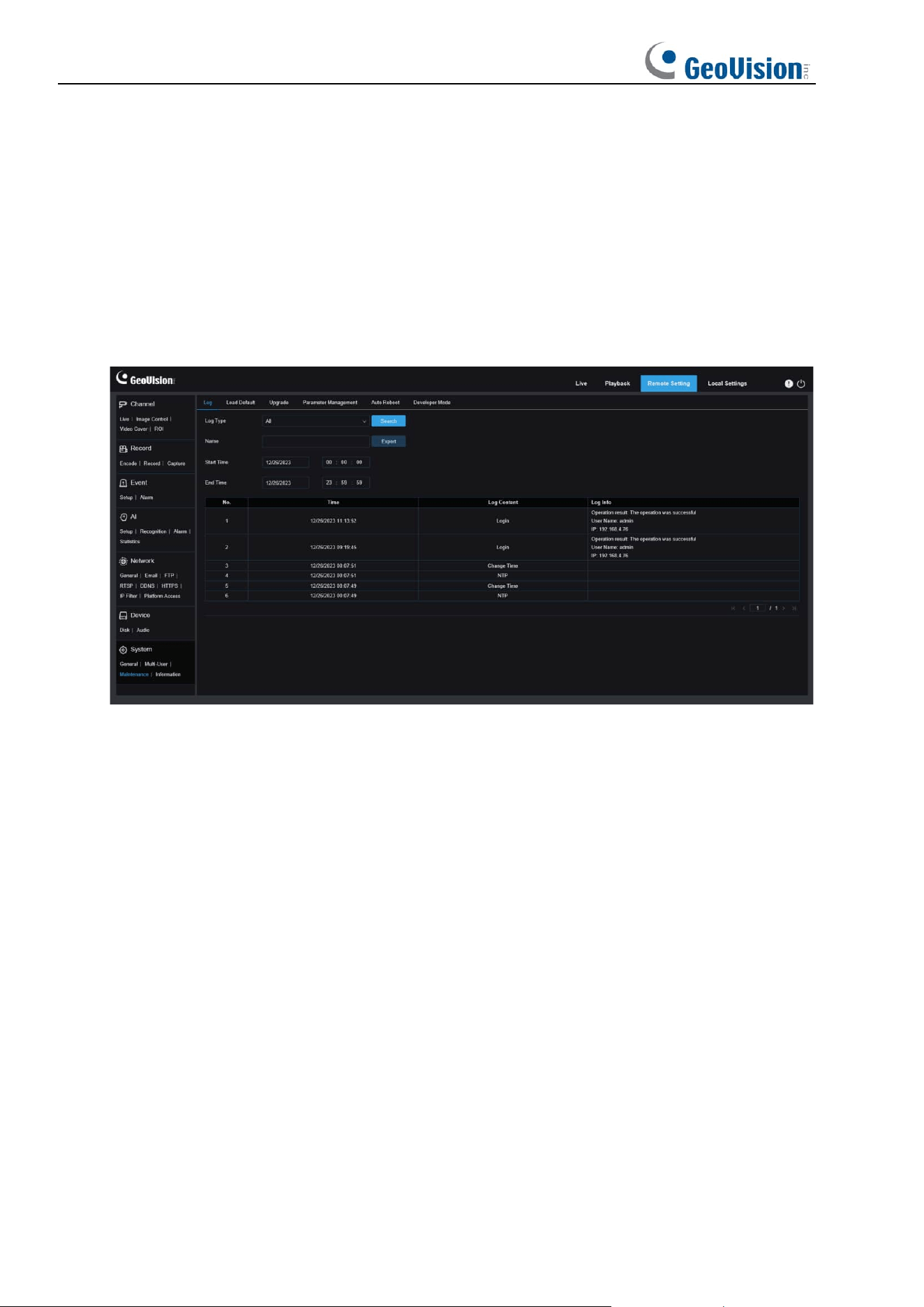
135
8.10.3 System Maintenance
This menu enables you to search for and view system logs, restore factory settings, upgrade
the system, export and import system parameters, and configure automatic system restart.
8.10.3.1 Log Management
The system log displays important system events, such as motion alarms and system
warnings. You can easily import backup files in the system log to your computer within a set
time range.
Log Search and Backup:
1. Click the field next to
Start Time
and select the start date and time from the on-screen
calendar.
2. Click the field next to
End Time
and select the end date and time from the on-screen
calendar.
3. Select the event type you want to search for from the drop-down list next to
Log Type
, or
select
All
to view the entire system log for the selected time range. The type options
include:
System
: System settings, restart, automatic restart, upgrade, time settings, and NTP.
Configuration
: IPC live control, private area settings, recording mode settings,
recording plan settings, main stream settings, network settings, substream settings,
email settings, color settings, motion detection settings, hard disk settings, multi-user
settings, NTP settings, image control, mobile stream settings, RTSP settings, IP filter
settings, restore factory settings, audio settings, video tampering alarm settings,
export settings, and import settings.
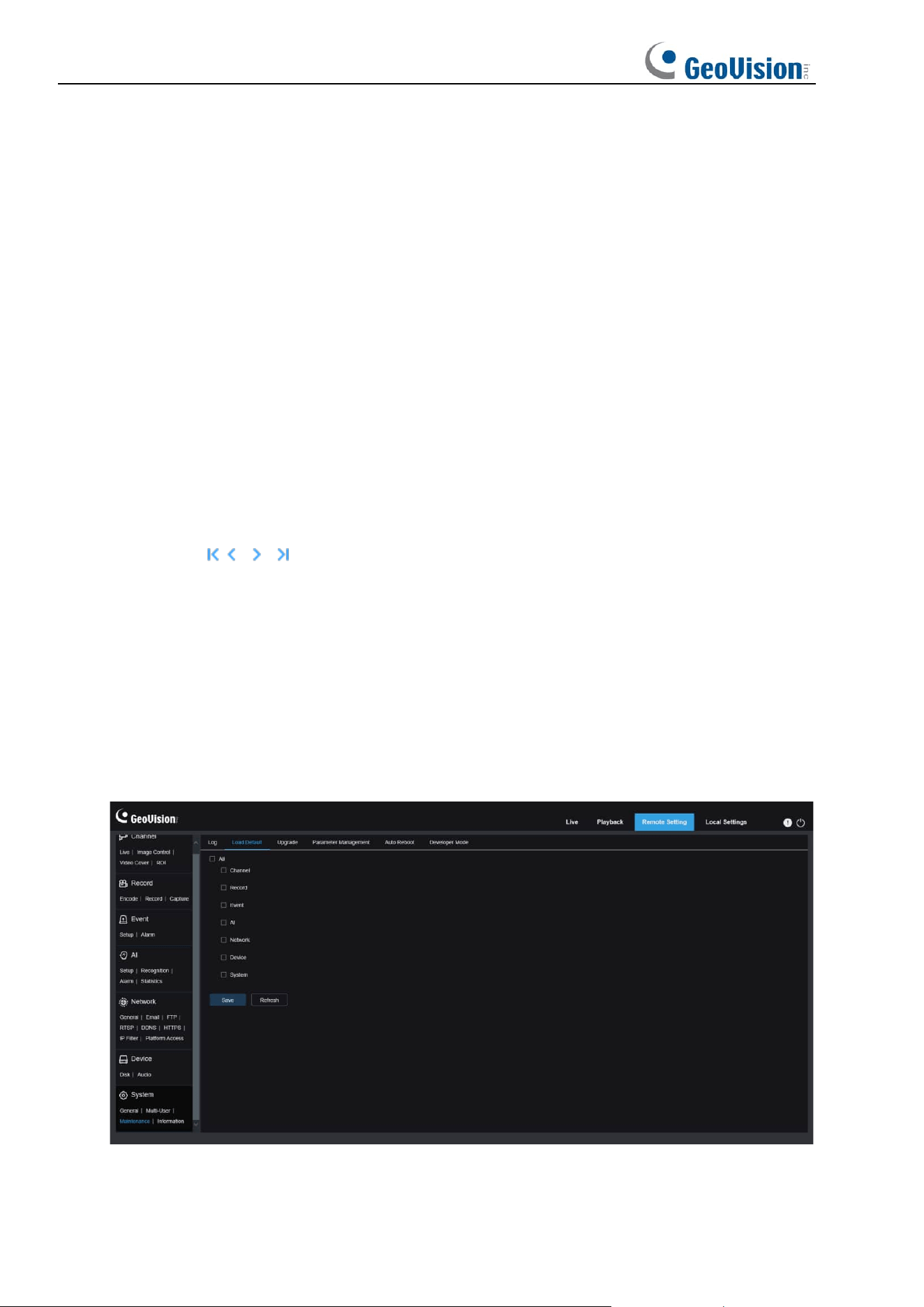
136
Alarm:
Start of motion detection, end of motion detection, start of I/O alarm, end of
I/O alarm, start of PID, end of PID, start of LCD, end of LCD, start of SOD, end of
SOD, start of PD&VD, end of PD&VD, start of FD, end of FD, start of CC, end of CC,
start of CD, end of CD, start of QD, end of QD, start of sound alarm, and end of sound
alarm.
Account:
Log in, log out, and switch users.
Record:
Search, playback, and backup.
Storage:
Formatting HDD, HDD full, and HDD error.
Network:
Network disconnected, network online, network exception, and Network
Mode changed.
4. Select the event type you want to search for from the drop-down list next to
Minor Type
(this menu is unavailable if ALL is selected for Log Type), or select
All
to view the entire
system log for the selected time range.
5. Click
Search
.
6. Browse system logs from the selected time range:
7. Use the / button in the lower right corner of the menu to switch between pages
of system log events.
Enter the name of the exported file in the field next to Name. Click Export to create the
backup of system logs.
8.10.3.2 Load Default
Reset the device to factory settings. You can choose to reset all the settings at a time, or the
settings on a specific menu. Note: Restoring the default Settings will not delete videos and
snapshots stored in the memory card.
Select the item to restore, or All to select all items. Click "Save" to load the default settings for
the selected items.
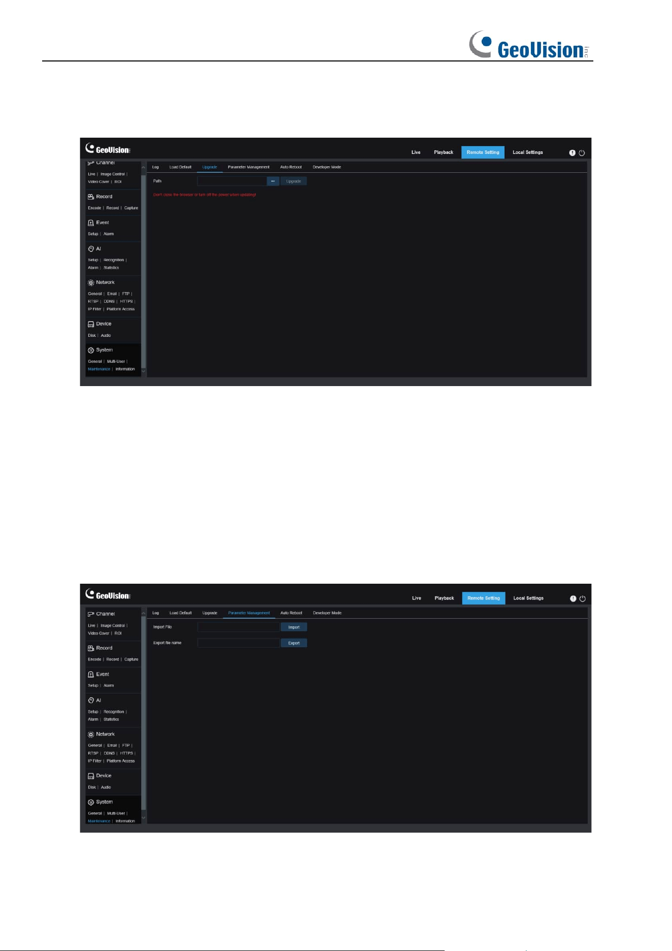
137
8.10.3.3 System Upgrade
This menu allows you to upgrade firmware.
1. Place the firmware file (.sw) into the HDD of your PC.
2. Click "
…
" next to "
Path
" to select the firmware file from your PC.
3. Click the
Upgrade
button to start system upgrade. The system upgrade will take about 2
to 3 minutes. Do not power off the device or close your Web browser while system
upgrade is in progress.
8.10.3.4 Parameter Management
You can export the configured parameters to your PC or import the exported configuration file
from your PC to the device.
Import File: Click the field to display the path window. Select the parameter file and then click
Import to start importing parameters.
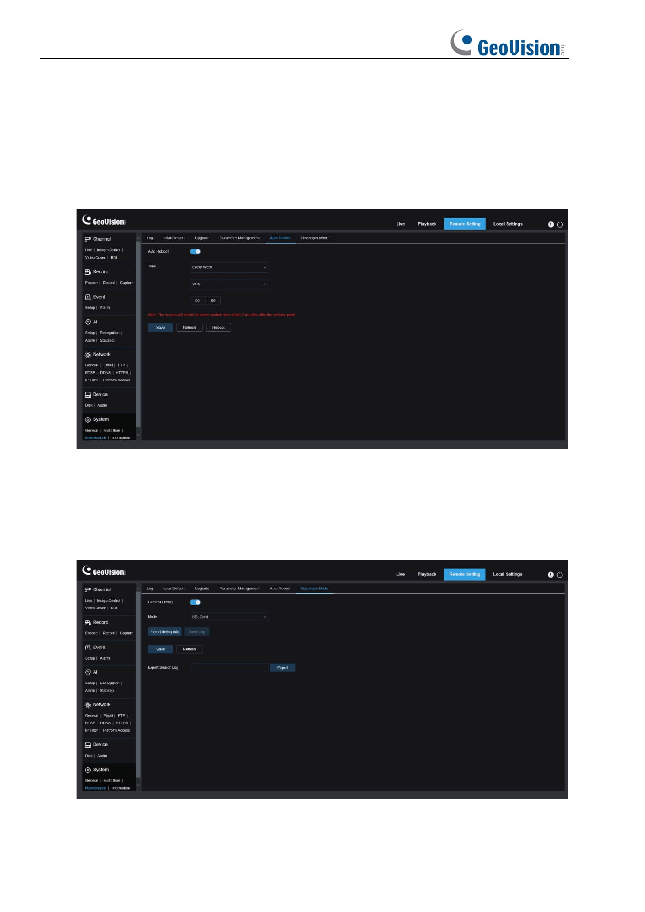
138
Export File Name: Click the field to enter the name of the file to which parameters are
exported. Click Export to export parameters.
8.10.3.5 Auto Reboot
This menu enables the system to automatically reboot. You are advised to enable this function
to guarantee the stable operation of the device.
Auto Reboot
: Used to turn on or off email.
Time: You can set IPC to reboot by day, week, or month.
8.10.3.6 Developer Mode
You can export P2P information of the IPC to your PC.
Export Debug Log: Click the field to enter the name of the file to which parameters are
exported. Click Export to export parameters.
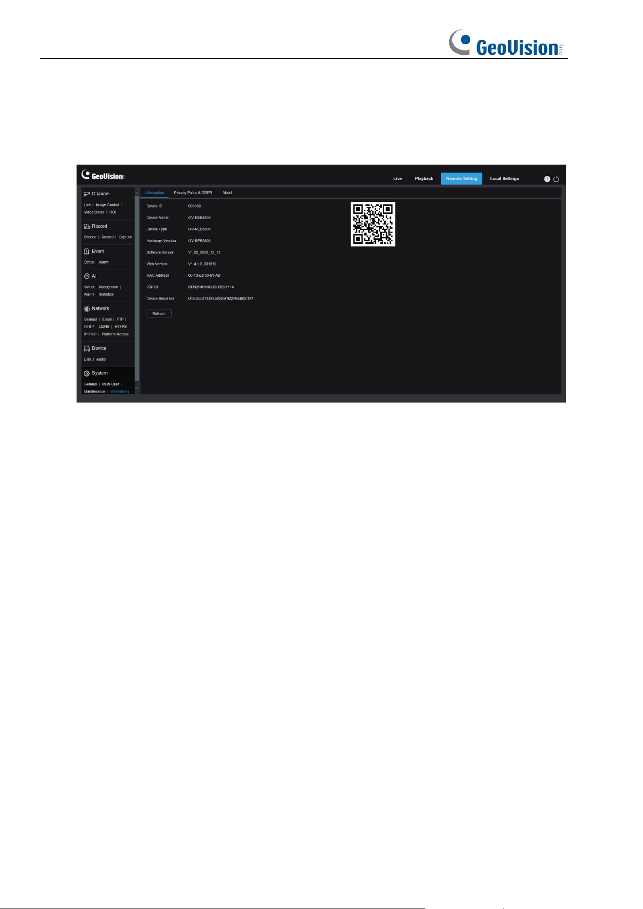
139
8.10.4 System Information
This menu allows you to view system information, such as device ID, device model, MAC
address, firmware version, and so on.
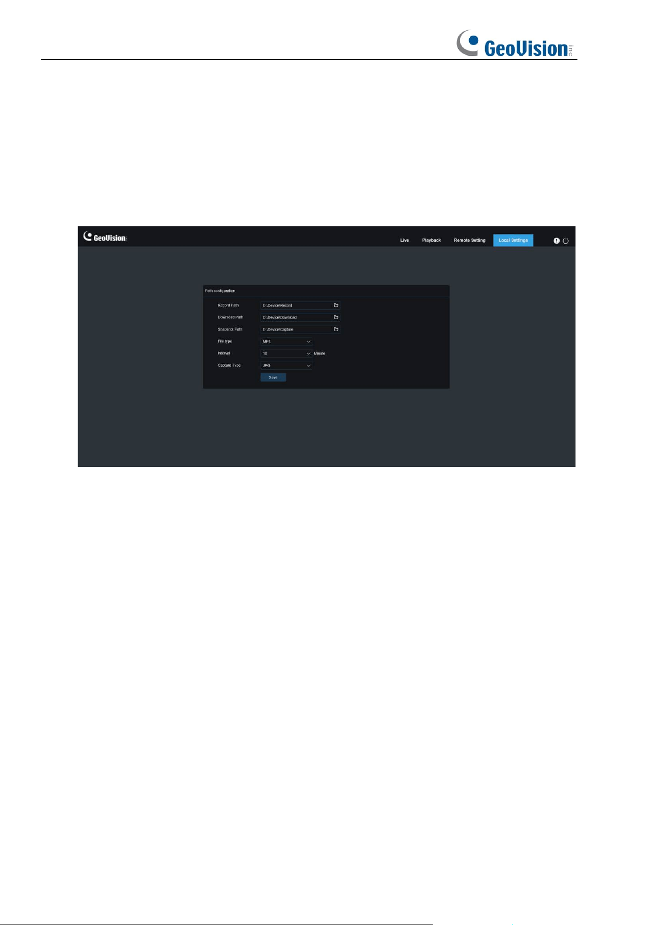
140
9 Local Settings
This menu allows you to set the path for storing videos and downloaded and captured image
files, as well as the format of videos and captured images.
Note: You can skip this page when you access the web client from Safari 12 and later,
Chrome 57 and later, Firefox 52 and later, and Edge 41.