English
Français
Español
Italiano
Português
ǼȜȜȘȞȚțȐ
Türkçe
Svenska
Deutsch
Nederlands
Ɋɭɫɫɤɢɣ
Dansk
ýHVNê
Magyar
Polski
<ORIGINAL>
Prior to use, thoroughly read the instructions in this manual to use the product correctly.
Retain for future reference.
Make sure that this CD-ROM and the Installation Manual are passed on to any future users.
To ensure safety and proper operation of the remote controller, the remote controller should
only be installed by qualified personnel.
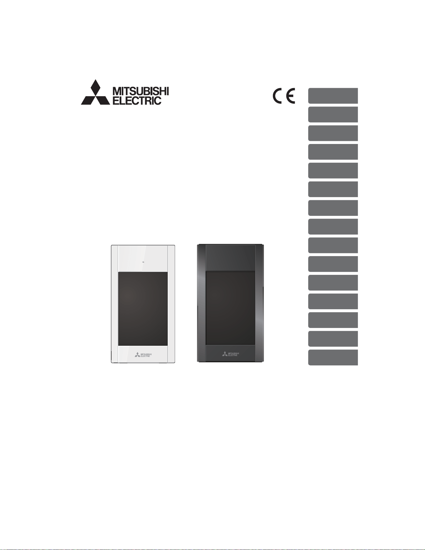
CITY MULTI Control System
and Mitsubishi Mr. SLIM Air Conditioners
MA Touch Remote Controller
PAR-CT01MAA-PB
PAR-CT01MAA-SB
PAR-CT01MAA-S
PAR-CT01MAR-PB
PAR-CT01MAR-SB
Instruction Book


Contents
Safety precautions ................................................4
Controller components .........................................6
Controller interface - Status display/Main display ................6
Controller interface - Menu screen ......................................8
Display - Status display/Main display ................................10
Menu structure and icons ...................................12
Menu structure ...................................................................12
Icon explanations ...............................................................15
Basic operations .................................................16
Power ON/OFF ..................................................................16
Operation mode, temperature, fan speed, vane, louver,
and ventilation (Lossnay) settings .....................................17
Navigating through the menu .............................22
Main menu list ....................................................................22
Navigating through the Main menu ....................................24
Function settings ................................................25
High power .........................................................................25
Manual vane angle ............................................................26
Timer (On/Off timer) ...........................................................29
Timer (Auto-Off timer) ........................................................32
Weekly timer ......................................................................34
OU silent mode ..................................................................37
Night setback .....................................................................40
Restriction .......................................................................... 43
Energy saving ....................................................................49
Clock .................................................................................. 54
Daylight saving time ...........................................................56
Main display .......................................................................58
Icon explanation .................................................................59
Brightness .......................................................................... 61
Language selection ............................................................62
Design ................................................................................ 64
Touch panel calibration ......................................................66
Touch panel cleaning .........................................................68
Initialize remote controller ..................................................70
Remote controller information ............................................72
Troubleshooting ..................................................74
Error information ................................................................74
No occupancy Auto-OFF ...................................................77
Maintenance .......................................................78
Filter information ................................................................78
Specifications .....................................................80
Controller specifications .....................................................80
Function list (as of October 1, 2017) ..................................81
List of functions that can/cannot be used in combination ..82
4
Safety precautions
•
Thoroughly read the following safety precautions before using the unit.
•
Observe these precautions carefully to ensure safety.
WARNING
Indicates a risk of death or serious injury.
CAUTION
Indicates a risk of serious injury or structural damage.
•
After reading this manual, pass it on to the end user to retain for future reference.
•
Keep this manual for future reference and refer to it as necessary. This manual should be made available
to those who repair or relocate the controller. Make sure that the manual is passed on to any future
users.
General precautions
WARNING
Do not install the unit in a place where large
amounts of oil, steam, organic solvents, or corrosive
gases, such as sulfuric gas, are present or where
acidic/alkaline solutions or sprays are used
frequently. These substances can compromise the
performance of the unit or cause certain components
of the unit to corrode, which can result in electric
shock, malfunctions, smoke, or fire.
To reduce the risk of shorting, current leakage,
electric shock, malfunctions, smoke, or fire, do not
wash the controller with water or any other liquid.
To reduce the risk of electric shock, malfunctions,
smoke or fire, do not operate the switches/buttons or
touch other electrical parts with wet hands.
When disinfecting the unit using alcohol, ventilate
the room adequately. The fumes of the alcohol
around the unit may cause a fire or explosion when
the unit is turned on.
To reduce the risk of injury or electric shock, before
spraying a chemical around the controller, stop the
operation and cover the controller.
To reduce the risk of injury or electric shock, stop the
operation and switch off the power supply before
cleaning, maintaining, or inspecting the controller.
If any abnormality (e.g., burning smell) is noticed,
stop the operation, turn off the power switch, and
consult your dealer. Continued use of the product
may result in electric shock, malfunctions, or fire.
Properly install all required covers to keep moisture
and dust out of the controller. Dust accumulation and
water can cause electric shock, smoke, or fire.
CAUTION
To reduce the risk of fire or explosion, do not place
flammable materials or use flammable sprays
around the controller.
To reduce the risk of damage to the controller, do not
directly spray insecticide or other flammable sprays
on the controller.
To reduce the risk of environmental pollution, consult
an authorized agency for proper disposal of remote
controller.
To reduce the risk of electric shock or malfunctions,
do not touch the touch panel, switches, or buttons
with a pointy or sharp object.
5
To reduce the risk of injury and electric shock, avoid
contact with sharp edges of certain parts.
To avoid injury from broken glass, do not apply
excessive force on the glass parts.
To reduce the risk of injury, wear protective gear
when working on the controller.
Precautions for moving or repairing the controller
WARNING CAUTION
The controller should be repaired or moved only by
qualified personnel. Do not disassemble or modify
the controller.
Improper installation or repair may cause injury,
electric shock, or fire.
To reduce the risk of shorting, electric shock, fire, or
malfunction, do not touch the circuit board with tools
or with your hands, and do not allow dust to
accumulate on the circuit board.
Additional precautions
To avoid damage to the controller, use appropriate
tools to install, inspect, or repair the controller.
This controller is designed for exclusive use with the
Building Management System by Mitsubishi Electric.
The use of this controller for with other systems or
for other purposes may cause malfunctions.
This appliance is not intended for use by persons
(including children) with reduced physical, sensory or
mental capabilities, or lack of experience and
knowledge, unless they have been given supervision
or instruction concerning use of the appliance by a
person responsible for their safety.
Children should be supervised to ensure that they do
not play with the appliance.
To avoid discoloration, do not use benzene, thinner,
or chemical rag to clean the controller. To clean the
controller, wipe with a soft cloth soaked in water with
mild detergent, wipe off the detergent with a wet
cloth, and wipe off water with a dry cloth.
To avoid damage to the controller, provide protection
against static electricity.
This appliance is intended to be used by expert or
trained users in shops, in light industry and on farms,
or for commercial use by lay persons.
If the supply cord is damaged, it must be replaced by
the manufacturer, its service agent or similarly
qualified persons in order to avoid a hazard.
6
Controller components
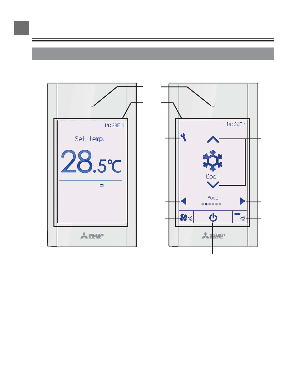
Controller interface - Status display/Main display
Status display Main display
④
③
⑤
②
⑦
⑥
⑧
①
⑨
7
①
Touch panel &
Backlit full color LCD
Operation settings will appear.
When the backlight is off, pressing any
area switches the screen to the Status
display. While the Status display is
displayed, pressing any area switches the
screen to the Main display.
②
ON/OFF
button
Press to turn ON/OFF the indoor unit.
③
Setting
button
Press to bring up the Main menu.
When the menu operation is locked, an
administrator password is required.
④
◀
button
Press to switch the setting items in the
following order: louver, ventilation, vane,
fan speed, operation mode, and preset
temperature.
⑤
▶
button
Press to switch the setting items in the
following order: preset temperature,
operation mode, fan speed, vane,
ventilation, and louver.
⑥
▲
▼
button
Press to change the contents of the
setting selected in ④ and ⑤ above.
⑦
Fan speed shortcut button
Press to directly access the fan speed
settings screen.
⑧
Vane shortcut button
Press to directly access the vane settings
screen.
⑨
ON/OFF lamp
This lamp lights up in green while the unit
is in operation unless “LED lighting” is set
to “No”. It blinks while the remote
controller is starting up or when there is
an error.
When the ON/OFF operation is locked,
② will not be displayed.
When the setting item is switched with
the ④ or ⑤ button, if the operation of
the selected setting item is locked, the
item will not be displayed.
If the operation of the fan speed or
vane is locked, the item ⑦ or ⑧ will not
be displayed.
The setting contents cannot be
changed with the ⑥ button when the
setting item is centrally controlled by
the system controller.
8
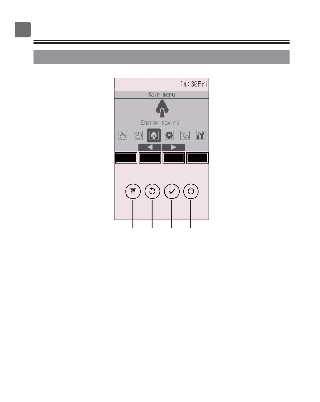
Controller components
@@@Controller interface - Menu screen
④③②①
⑤⑥⑦⑧
9
①
ON/OFF
button
Press to turn ON/OFF the indoor unit.
②
SELECT
button
Press to save the setting.
③
RETURN
button
Press to return to the previous screen.
When the Main menu is displayed,
pressing this button will display the Status
display.
④
MENU
button Page 24
Press to bring up the Main menu.
⑤
Function button
F1
Menu screen: The button function varies
with the screen.
⑥
Function button
F2
Main menu: Press to move the cursor left.
Menu screen: The button function varies
with the screen.
⑦
Function button
F3
Main menu: Press to move the cursor
right.
Menu screen: The button function varies
with the screen.
⑧
Function button
F4
Menu screen: The button function varies
with the screen.
The functions of the function buttons
change depending on the screen.
Refer to the button function guide that
appears at the bottom of the LCD for
the functions they serve on a given
screen.
Main menu Menu screen
Function guide
⑤⑥⑦⑧ ⑤⑥⑦⑧
10
Controller components
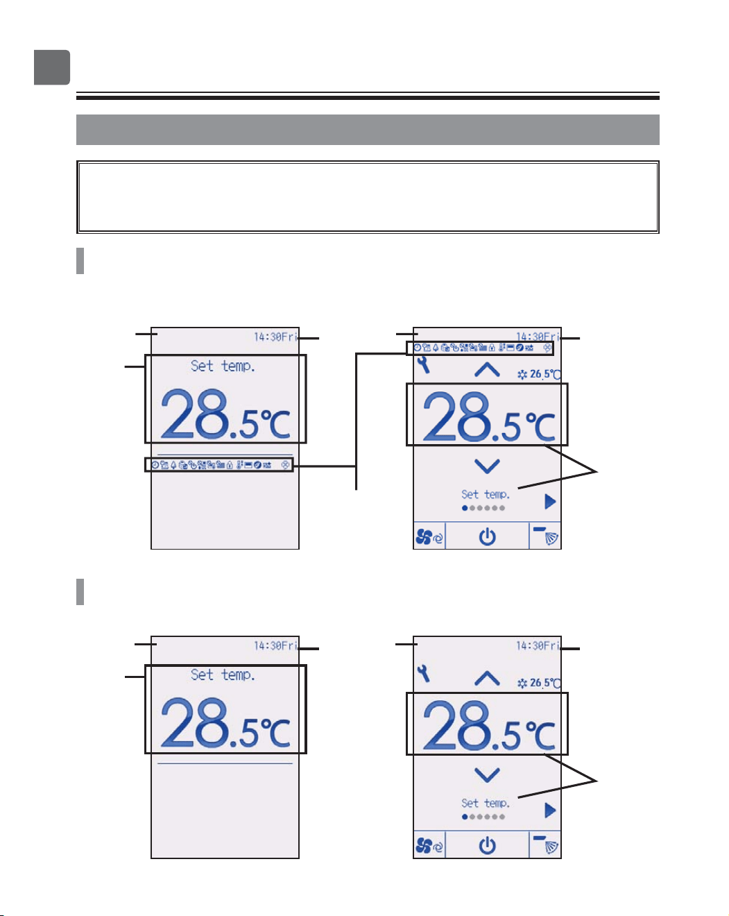
@@@Display - Status display/Main display
The Status display and Main display can be displayed in two different modes:
“Full” and “Basic.”
The factory setting is “Full.” For how to switch the mode, refer to page 58.
Full mode
Status display Main display
Basic mode
Status display Main display
①
③
④
–
⑯
⑰
③
②
⑰
①
③
⑰
③
②
⑰
* All icons are displayed for explanation.
11
①
Preset temperature or room
temperature
Preset temperature or room temperature
appears here.
(See the Installation Manual.)
②
Setting item and setting
contents Page 17
The setting items “Preset temperature”
↔ “Operation mode” ↔ “Fan speed”
↔ “Vane” ↔ “Ventilation” ↔ “Louver,” and
their setting contents appear here.
“Centrally controlled” appears for a certain
period of time when a centrally-controlled
item is operated.
③
Clock
Current time appears here.
(See the Installation Manual.)
④
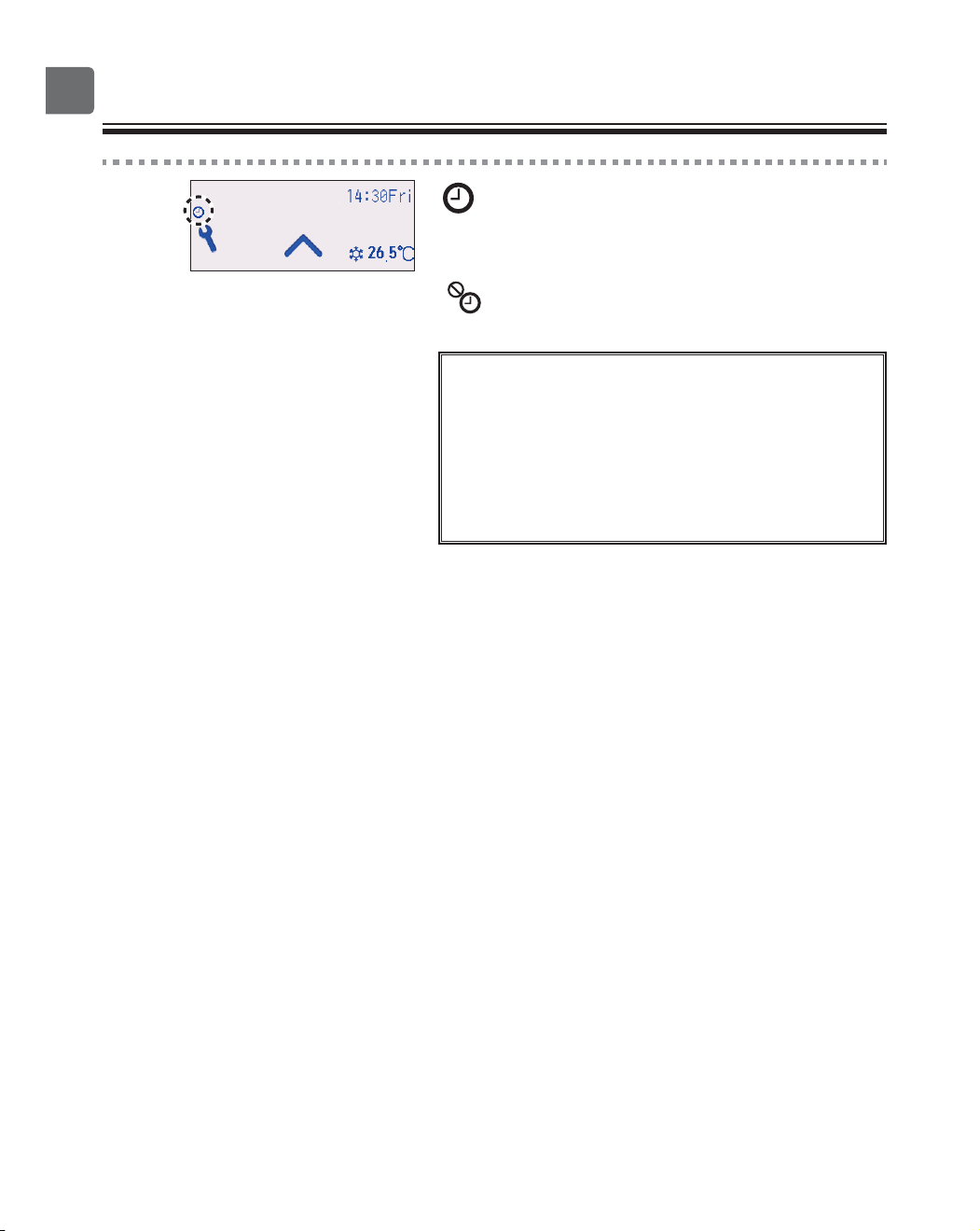
Page 29, 32, 40
Appears when the On/Off timer (Page
29), Night setback (Page 40), or Auto-
off timer (Page 32) function is enabled.
appears when the timer is disabled by
the centralized control system.
⑤
Page 34
Appears when the Weekly timer is
enabled.
⑥
Page 51
Appears while the units are operated in the
energy-save mode. (Will not appear on
some models of indoor units)
⑦
Page 37
Appears while the outdoor units are
operated in the silent mode.
⑧
Appears when the ON/OFF operation is
centrally controlled.
⑨
Appears when the operation mode is
centrally controlled.
⑩
Appears when the preset temperature is
centrally controlled.
⑪
Appears when the filter reset function is
centrally controlled.
⑫
Page 46
Appears when the buttons are locked.
⑬
Page 43
Appears when the preset temperature
range is restricted.
⑭
Appears when the built-in thermistor on the
remote controller is activated to monitor
the room temperature.
appears when the thermistor on the
indoor unit is activated to monitor the room
temperature.
⑮
Appears when an energy-saving operation
is performed using a “3D i-See sensor”
function.
⑯
Page 78
Indicates when filter needs maintenance.
⑰
Preliminary error display
An error code appears during the
preliminary error.
12
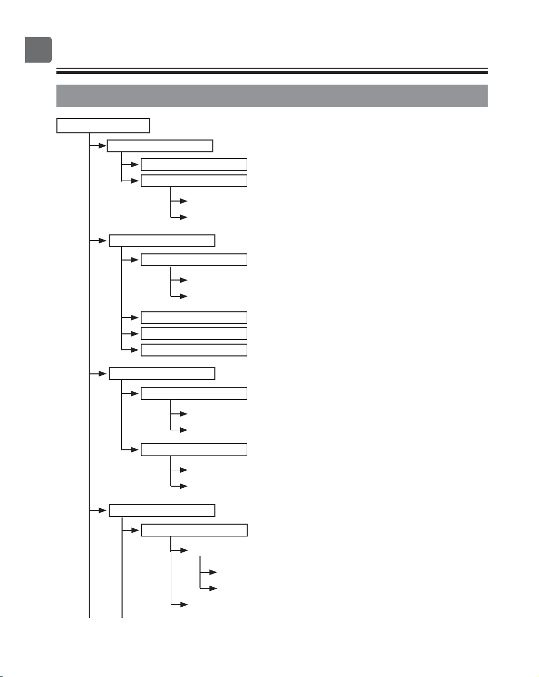
Menu structure and icons
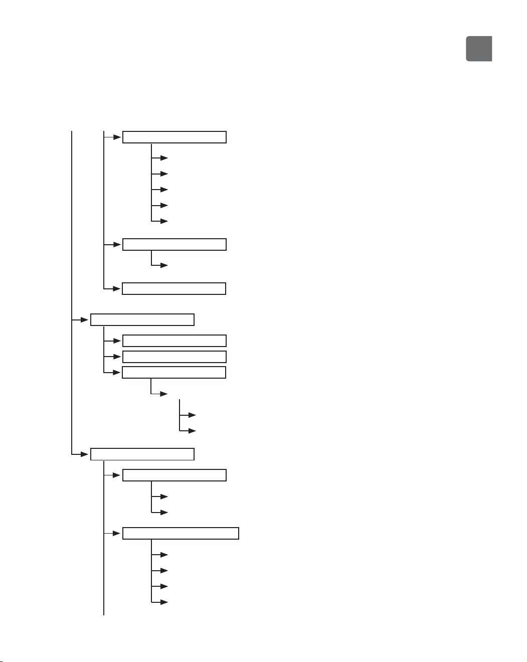
Menu structure
Main menu
High power
.......................................
Page 25
Comfort
Manual vane angle
.............................
Page 26
3D i-See sensor
...................................
Refer to the indoor unit Instruction Book.
Timer
On/Off timer
........................................
Page 29
Auto-Off timer
.....................................
Page 32
Weekly timer
.......................................
Page 34
OU silent mode
.......................................
Page 37
Night setback
.......................................
Page 40
Restriction
Temp. range
.........................................
Page 43
Operation locked
..................................
Page 46
Energy saving
Auto return
...........................................
Page 49
Schedule
.............................................
Page 51
Basic setting
Clock
Clock
.........................................
Page 54
Daylight saving time
...................
Page 56
Administrator password
........................
Refer to the Installation Manual.
Operation
Timer menu
Energy saving
Initial setting menu
13
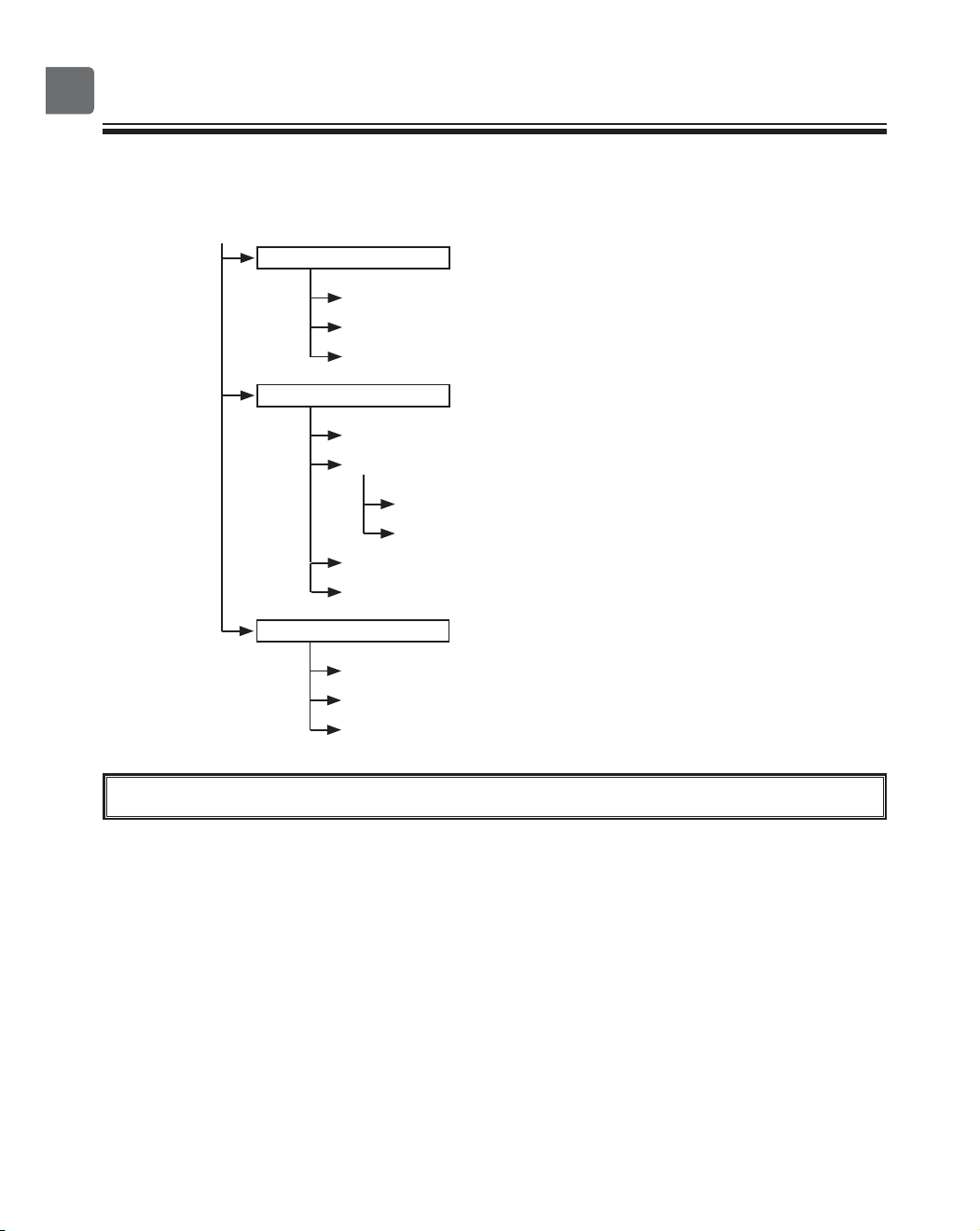
Display setting
Main display
.........................................
Page 58
Display details (Icon explanation etc.)
.........
Refer to the Installation Manual.
Brightness
...........................................
Page 61
Language selection
..............................
Page 62
Design
.................................................
Page 64
Operation setting
Auto mode
...........................................
Refer to the Installation Manual.
Touch panel
.......................................
Page 66
Error information
.......................................
Page 74
Filter information
.......................................
Page 78
Cleaning
Auto descending panel
.......................
Refer to the Instructions Manual that
came with the automatic elevating panel.
Descending operation
................
Refer to the Instructions Manual that
came with the automatic elevating panel.
Descending adjustment
..............
Refer to the Instructions Manual that
came with the automatic elevating panel.
Test run menu
Test run
...............................................
Refer to the indoor unit Installation
Manual.
Drain pump test run
............................
Refer to the indoor unit Installation
Manual.
Maintenance information
..................................
Refer to the indoor unit Installation
Manual.
Model name input
...............................
Refer to the indoor unit Installation
Manual.
Serial No. input
...................................
Refer to the indoor unit Installation
Manual.
Dealer information input
.....................
Refer to the indoor unit Installation
Manual.
Initialize maintenance info.
.................
Refer to the indoor unit Installation
Manual.
Maintenance menu
Service menu
14
Menu structure and icons
Settings menu
Function setting (Mr. SLIM)
................
Refer to the Installation Manual.
Function setting (CITY MULTI)
...........
Refer to the Installation Manual.
Lossnay (CITY MULTI only)
................
Refer to the Installation Manual.
Check menu
Error history
........................................
Refer to the Installation Manual.
Diagnosis
Self check
..................................
Refer to the Installation Manual.
Remote controller check
.............
Refer to the Installation Manual.
Smooth maintenance (Mr. SLIM only)
....
Refer to the indoor unit Installation
Manual.
Request code (Mr. SLIM only)
............
Refer to the indoor unit Installation
Manual.
Other menu
Maintenance password
.......................
Refer to the Installation Manual.
Initialize remote controller
..................
Page 70
Remote controller information
............
Refer to the Installation Manual.
Not all functions are available on all models of indoor units.
15
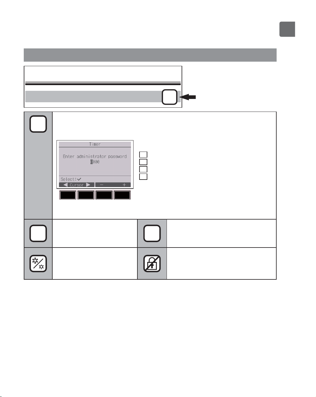
Icon explanations
Controller operation
Timer
P
P
The administrator or maintenance user password must be entered on the
password input screen to change settings. There is no settings that can skip this
process.
F1
: Press to move the cursor left.
F2
: Press to move the cursor right.
F3
: Press to decrease the value by 1.
F4
: Press to increase the value by 1.
*
Changes cannot be made unless the
correct password is entered.
ON
Indicates settings that can be
changed only while the units
are in operation.
OFF
Indicates settings that can be changed
only while the units are not in
operation.
Indicates settings that can be
changed only while the units
are operated in the Cool,
Heat, or Auto mode.
Indicates functions that are not
available when the buttons are locked
or the system is centrally controlled.
The table below
summarizes the square
icons used in this manual.
F4F3F2F1
16
Basic operations
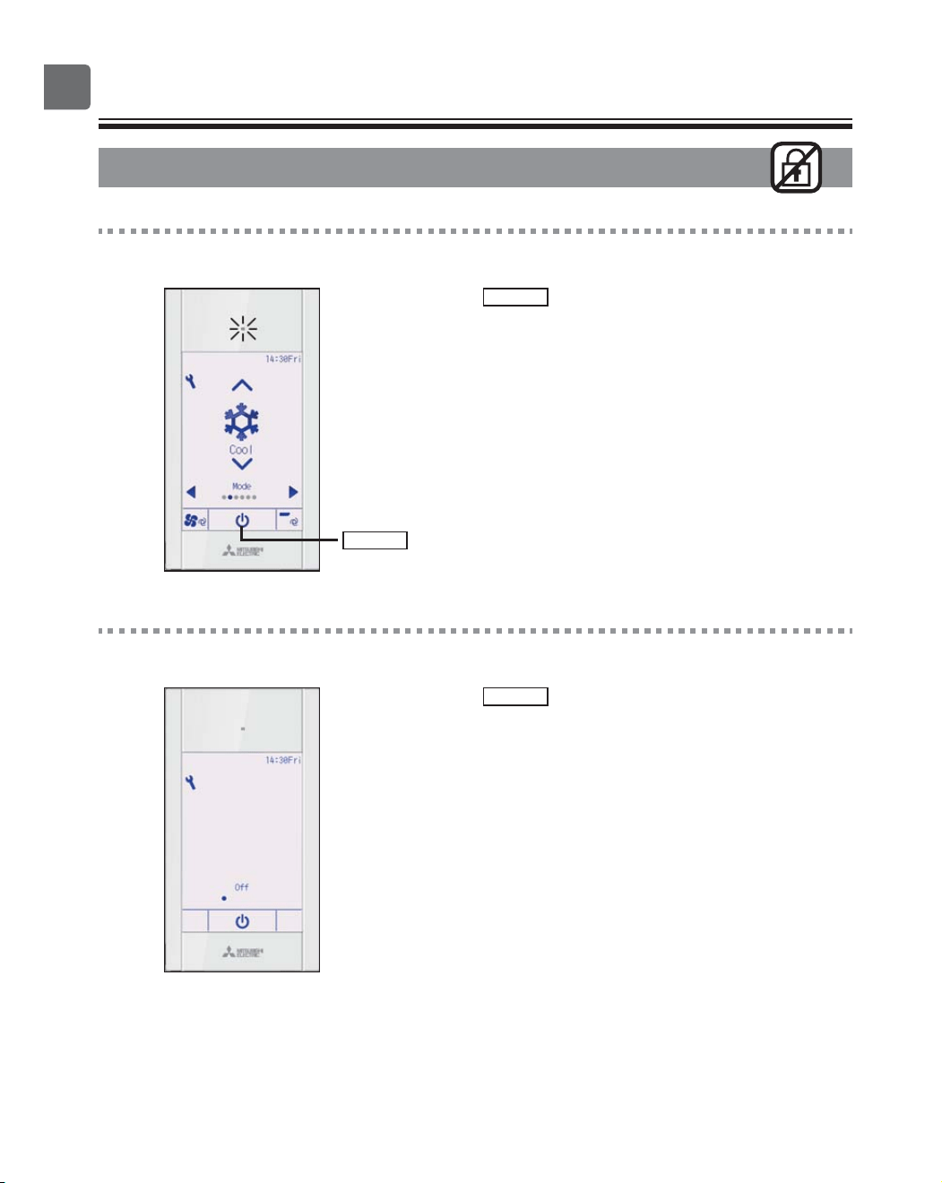
Power ON/OFF
Button operation
ON
Press the
ON/OFF
button.
The ON/OFF lamp will light up in green, and the
operation will start.
When “LED lighting” is set to “No,” the ON/OFF lamp will
not light up.
OFF
Press the
ON/OFF
button again.
The ON/OFF lamp will come off, and the operation will
stop.
ON/OFF
button
17
Operation mode, temperature, fan speed, vane,
louver, and ventilation (Lossnay) settings
ON
Button operation
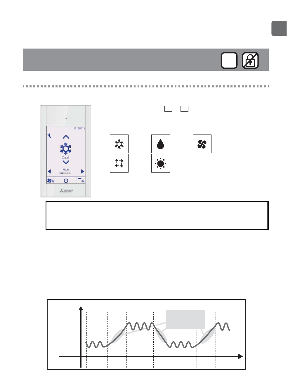
Operation mode
Each pressing of the
▼
or
▲
button cycles through the
following operation modes.
Select the desired operation mode.
Cool Dry Fan
Auto Heat
•
Operation modes that are not available to the connected indoor unit
models will not appear on the display.
What the blinking mode icon means
The mode icon will blink when other indoor units in the same refrigerant system (connected to the same
outdoor unit) are already operated in a different mode. In this case, the rest of the unit in the same
group can only be operated in the same mode.
<Auto (dual set point) mode>
When the operation mode is set to the Auto (dual set point) mode, two preset
temperatures (one each for cooling and heating) can be set. Depending on the room
temperature, indoor unit will automatically operate in either the Cool or Heat mode
and keep the room temperature within the preset range.
The graph below shows the operation pattern of indoor unit operated in the Auto
(dual set point) mode.
Preset temp.
(Cool)
Preset temp.
(Heat)
Operation pattern during Auto (dual set point) mode
Heat Cool
The room temperature
changes corresponding
to the change in the
outside temperature.
Heat
Room temperature
Cool
18
Basic operations
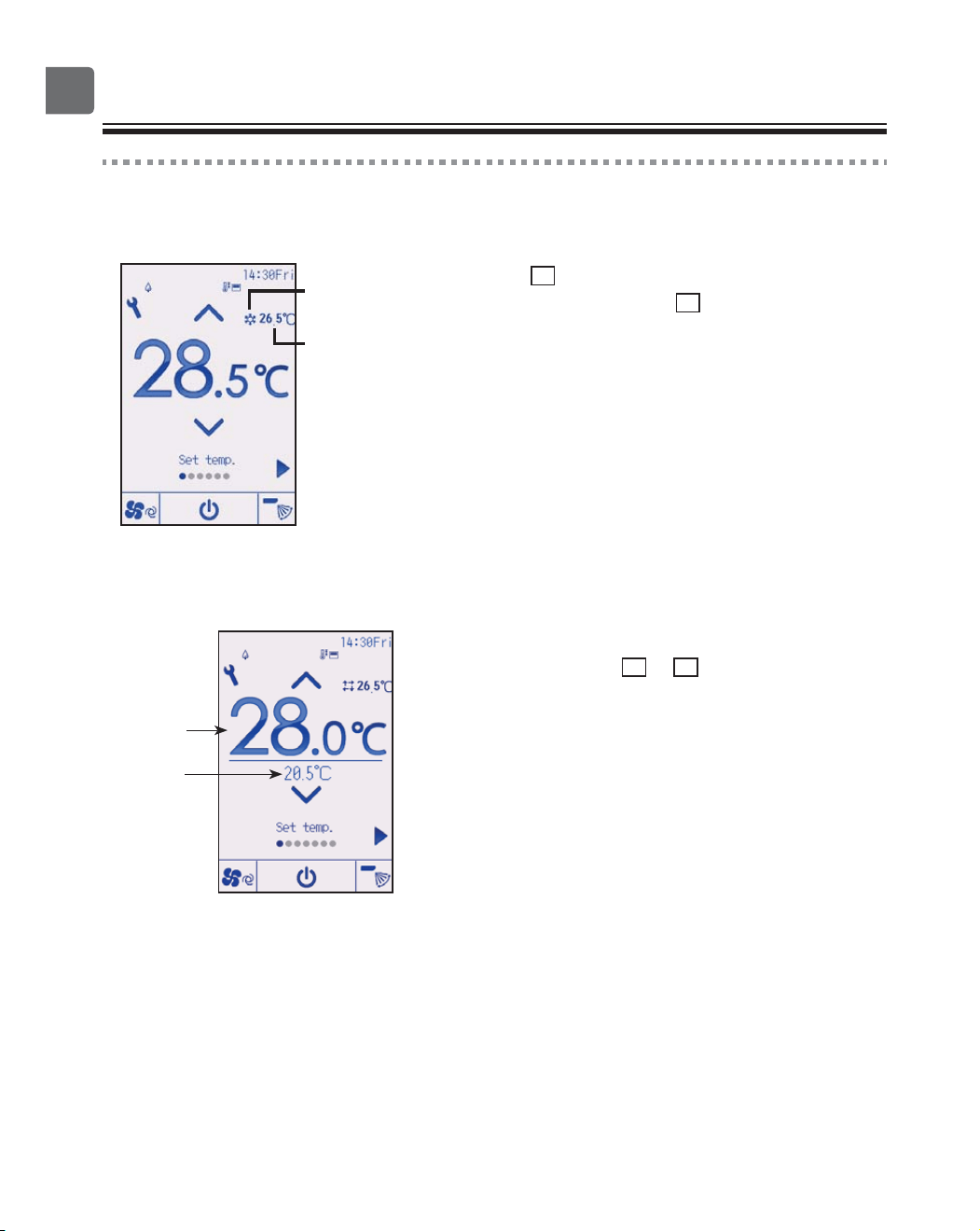
Preset temperature
<Cool, Dry, Heat, and Auto (single set point)>
Press the
▼
button to decrease the preset
temperature, and press the
▲
button to increase.
•
Refer to the table on page 19 for the settable
temperature range for different operation modes.
•
Preset temperature range cannot be set for Fan/
Ventilation operation.
•
Preset temperature will be displayed either in Centigrade
in 0.5- or 1-degree increments, or in Fahrenheit,
depending on the indoor unit model and the display mode
setting on the remote controller.
<Auto (dual set point) mode>
1
The current preset temperatures will appear.
Each pressing of the
◀
or
▶
button switches the
preset temperatures for cooling and heating.
Room temperature
(Refer to the
Installation Manual.)
Operation mode
Preset
temperature
for cooling
Preset
temperature
for heating
19
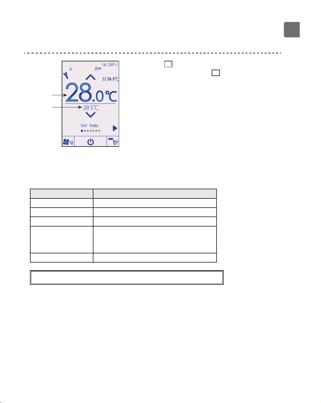
2
Press the
▼
button to decrease the selected
temperature, and press the
▲
button to increase.
•
Refer to the table below for the settable temperature
range for different operation modes.
•
The preset temperature settings for cooling and heating in
the Auto (dual set point) mode are also used by the Cool/
Dry and Heat modes.
•
The preset temperatures for cooling and heating in the
Auto (dual set point) mode must meet the conditions
below:
Preset cooling temperature is higher than preset heating temperature.
The minimum temperature difference requirement between cooling and
heating preset temperatures (varies with the models of indoor units
connected) is met.
If preset temperatures are set in a way that does not meet the minimum
temperature difference requirement, both preset temperatures will
automatically be changed within the allowable setting ranges.
Settable preset temperature range
Operation mode Preset temperature range
Cool/Dry 19 ~ 30 ºC (67 ~ 87 ºF)
Heat 17 ~ 28 ºC (63 ~ 83 ºF)
Auto (Single set point) 19 ~ 28 ºC (67 ~ 83 ºF)
Auto (Dual set points) [C ool]
Preset temperature range for the Cool mode
[H eat]
Preset temperature range for the Heat mode
Fan/Ventilation Not settable
The settable temperature range varies with the model of indoor units.
Preset
temperature
for heating
Preset
temperature
for cooling
20
Basic operations
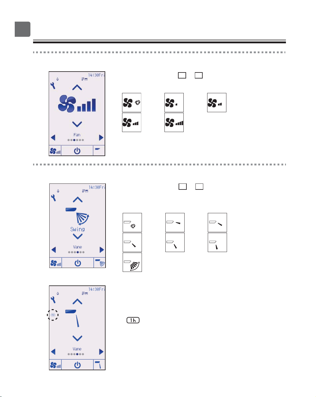
Fan speed
Each pressing of the
▼
or
▲
button cycles through the
following fan speeds.
Auto
•
The available fan speeds depend on the models of connected
indoor units.
Vane setting
(Sample screen on CITY MULTI)
Each pressing of the
▼
or
▲
button cycles through the
following vane settings.
Select the desired setting.
Auto
Auto Step 1 Step 2
Step 3 Step 4 Step 5
Swing
Swing
Select “Swing” to move the vanes up and down
automatically.
When set to “Step 1” through “Step 5”, the vane will be fixed
at the selected angle.
•
at the left of the vane setting icon
This icon will appear when the vane is set to Step 2, 3, 4, or 5 and
the fan operates at low speed during cooling or dry operation
(depends on the model).
The icon will go off in an hour, and the vane setting will
automatically change.
21
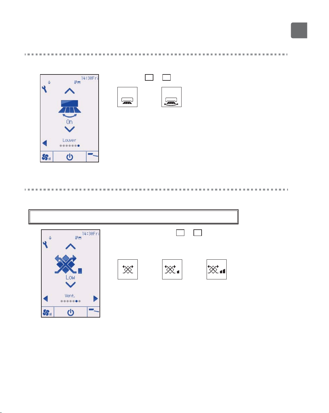
Louver setting
(Sample screen on CITY MULTI)
Press the
▼
or
▲
button to turn on or off the louver swing.
Off
Off
On
On
Ventilation setting
The ventilation setting can be made even when the units are in operation.
(Sample screen on Mr. SLIM)
Each pressing of the
▼
or
▲
button cycles through the
following ventilation settings.
*
Settable only when Lossnay unit is connected.
Off Low High
The fan on some models of indoor units may be interlocked with certain
models of ventilation units.
22
Navigating through the menu
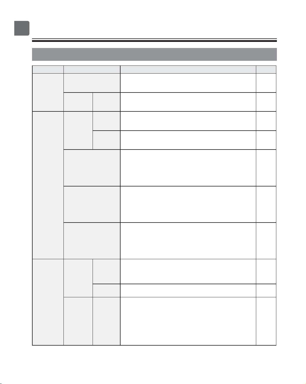
Main menu list
Main menu Setting items Setting details
Page
Operation High power Use to reach the comfortable room temperature quickly.
Units can be operated in the High-power mode for up to 30
minutes.
25
Comfort Manual
vane
angle
Use to fix each vane angle. 26
Timer Timer On/Off
timer
Use to set the operation On/Off times.
Time can be set in 5-minute increments.
*
Clock setting is required.
29
Auto-Off
timer
Use to set the Auto-Off time.
Time can be set to a value from 30 to 240 in 10-minute
increments.
32
Weekly timer Use to set the weekly operation On/Off times.
Up to eight operation patterns can be set for each day.
Two types of weekly schedules can be set.
*
Clock setting is required.
*
Not valid when the On/Off timer is enabled.
*
1ºC increments
34
OU silent mode Use to set the time periods in which priority is given to
quiet operation of outdoor units over temperature
control. Set the Start/Stop times for each day of the week.
Select the desired silent level from “Normal,” “Middle,” and
“Quiet.”
*
Clock setting is required.
37
Night setback Use to make Night setback settings.
Select “Yes” to enable the setting, and “No” to disable the
setting. The temperature range and the start/stop times can
be set.
*
Clock setting is required.
*
1ºC increments
40
Energy
saving
Restriction Temp.
range
Use to restrict the preset temperature range.
Different temperature ranges can be set for different operation
modes.
*
1ºC increments
43
Operation
locked
Use to lock selected functions.
The locked functions cannot be operated.
46
Energy
saving
Auto
return
Use to get the units to operate at the preset temperature
after performing energy-save operation for a specified
time period.
Time can be set to a value from 30 and 120 in 10-minute
increments.
*
This function will not be valid when the preset temperature
ranges are restricted.
*
1ºC increments
49
23
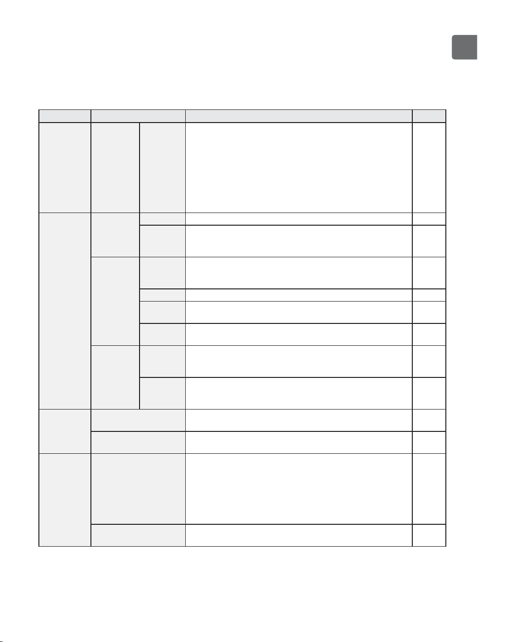
Main menu Setting items Setting details
Page
Energy
saving
Energy
saving
Schedule Set the start/stop times to operate the units in the
energy-save mode for each day of the week, and set the
energy-saving rate.
Up to four energy-save operation patterns can be set for
each day.
Time can be set in 5-minute increments.
Energy-saving rate can be set to a value from 0% and 50 to
90% in 10% increments.
*
Clock setting is required.
51
Initial
setting
Basic
setting
Clock Use to set the current time. 54
Daylight
saving
time
Sets the daylight saving time. 56
Display
setting
Main
display
Use to switch between "Full" and "Basic" modes for the
Status display and the Main display.
The default setting is “Full.”
58
Brightness
Use to adjust screen brightness. 61
Language
selection
Use to select the desired language. 62
Design Use to change the color of the Status display and Main
display.
64
Touch
panel
Touch
panel
calibration
Sets the calibration settings for the touch panel. 66
Touch
panel
cleaning
Temporarily makes the touch panel unresponsive to
touch to allow for cleaning.
68
Service Initialize remote
controller
Use to initialize the remote controller to the factory
shipment status.
70
Remote controller
information
Use to display the remote controller model name,
software version, and serial number.
72
Maintenance
Error information Use to check error information when an error occurs.
Error code, error source, refrigerant address, unit model,
manufacturing number, contact information (dealer's phone
number) can be displayed.
*
The unit model, manufacturing number, and contact
information need to be registered in advance to be
displayed.
74
Filter information Use to check the filter status.
The filter sign can be reset.
78
24
Navigating through the menu
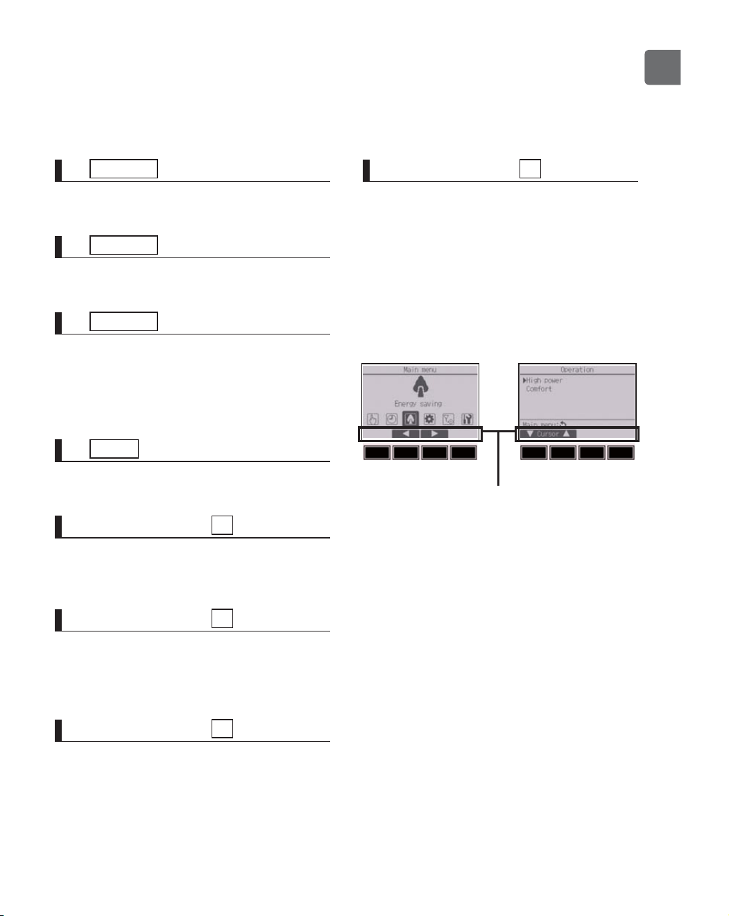
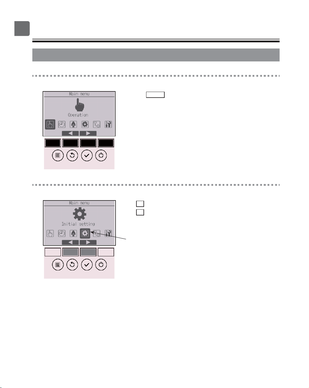
@@@Navigating through the Main menu
Button operation
Accessing the Main menu
Press the
Setting
button on the Main display.
The Main menu will appear.
Item selection
Press
F2
to move the cursor left.
Press
F3
to move the cursor right.
Cursor
25
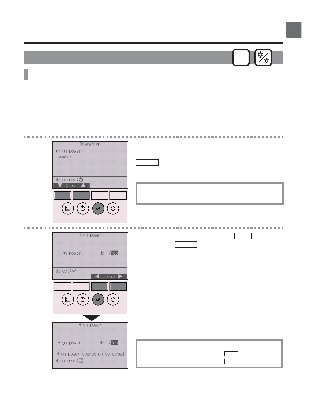
Function settings
High power
ON
Function description
High-power operation function allows the units to operate at higher-than-normal capacity so that the
room air can be conditioned to an optimum temperature quickly. This operation will last for up to 30
minutes, and the unit will return to the normal operation mode at the end of the 30 minutes or when
the room temperature reaches the preset temperature, whichever is earlier. The units will return to the
normal operation when the operation mode or fan speed is changed.
Button operation
1
Select “High power” from the Operation menu during
Cooling, Heating, or Auto operation, and press the
SELECT
button.
“High power” function is available only on the models
that support the function.
2
Move the cursor to “Yes” with the
F3
or
F4
button,
and press the
SELECT
button.
A confirmation screen will appear.
Navigating through the screens
To go back to the Main menu ...........
MENU
button
To return to the previous screen
.......
RETURN
button
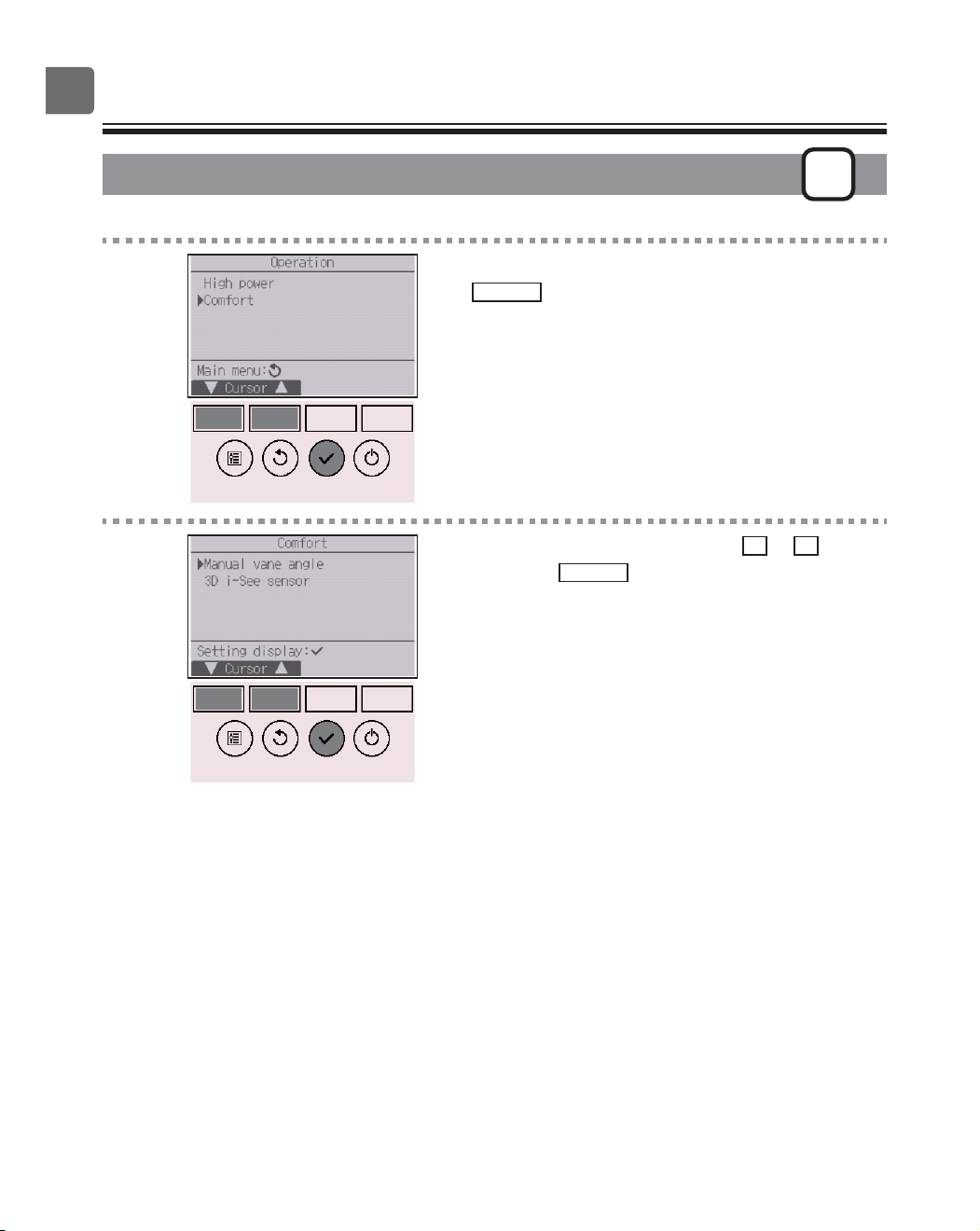
26
Function settings
Manual vane angle
OFF
Button operation
1
Select “Comfort” from the Operation menu, and press
the
SELECT
button.
2
Select “Manual vane angle” with the
F1
or
F2
button,
and press the
SELECT
button.
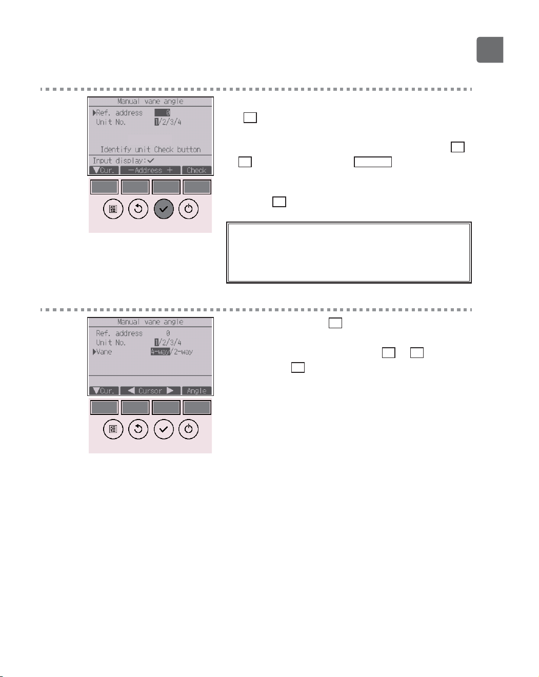
27
3
Move the cursor to “Ref. address” or “Unit No.” with
the
F1
button to select.
Select the refrigerant address and the unit number for
the units to whose vanes are to be fixed, with the
F2
or
F3
button, and press the
SELECT
button.
•
Ref. address: Refrigerant address
•
Unit No.: 1, 2, 3, 4
Press the
F4
button to confirm the unit.
The screen at left shows a sample display on
Mr. SLIM. On CITY MULTI units, “M-NET address” is
displayed instead of “Ref. address”, and the “Unit No.”
will not be displayed.
4
Select “Vane” with the
F1
button.
Select “4-way” or “2-way” with the
F2
or
F3
button,
and press the
F4
button.
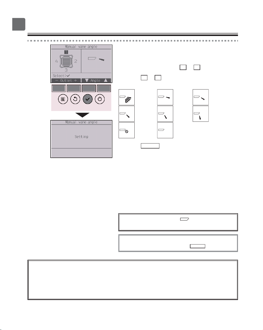
28
Function settings
5
The current vane setting will appear.
Select the desired outlets from “1,” “2,” “3,” “4,” or “1,
2, 3, 4 (all outlets)” with the
F1
or
F2
button.
Press the
F3
or
F4
button to go through the following
options and select the desired setting.
No setting
Step 1 Step 2
Step 3 Step 4 Step 5
Draft
reduction
*
All
outlets
Press the
SELECT
button to save the settings.
A screen will appear that indicates the setting
information is being transmitted.
The setting changes will be made to the selected
outlet.
The screen will automatically return to the previous
screen when the transmission is completed.
Make the settings for other outlets, following the
same procedures.
If all outlets are selected, will be displayed
the next time the unit goes into operation.
Navigating through the screens
To return to the previous screen ......
RETURN
button
*Draft reduction
The [Draft reduction] mode keeps the vane angle more horizontal than the angle of
Step 1 so that the airflow will not be directed toward the people.
This function can be set only for one outlet.
This function cannot be set for models with two or three outlets.
In the Draft reduction mode, the airflow may cause the ceiling discoloration.
29
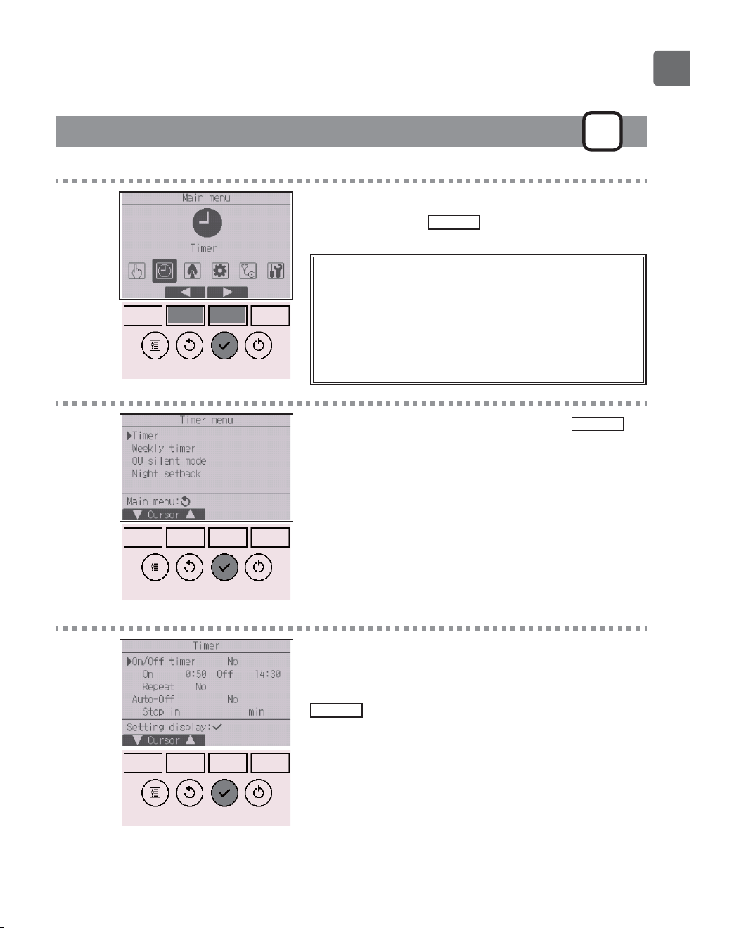
Timer (On/Off timer)
P
Button operation
1
Select “Timer” from the Main menu (refer to page
24), and press the
SELECT
button.
The On/Off timer will not work in the following
cases:
when On/Off timer is disabled, during an error, during
check (in the service menu), during test run, during
remote controller diagnosis, when the clock is not set,
during function setting, when the system is centrally
controlled (when On/Off operation or timer operation
from local remote controller is prohibited).
2
Move the cursor to “Timer,” and press the
SELECT
button.
3
The current settings will appear.
Move the cursor to “On/Off timer,” and press the
SELECT
button.
30
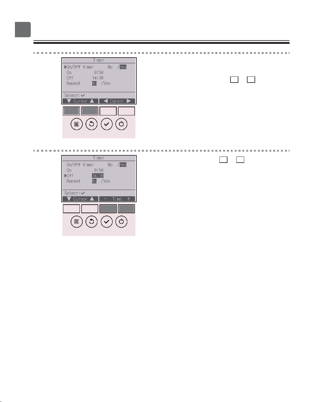
Function settings
4
The screen to set the timer will appear.
Select the desired item with the
F1
or
F2
button out
of “On/Off timer,” “On,” “Off,” or “Repeat.”
5
Change the setting with the
F3
or
F4
button.
•
On/Off timer: No (disable)/Yes (enable)
•
On: Operation start time
(settable in 5-minute increments)
*
Press and hold the button to rapidly advance the
numbers.
•
Off: Operation stop time
(settable in 5-minute increments)
*
Press and hold the button to rapidly advance the
numbers.
•
Repeat: No (once)/Yes (repeat)
31
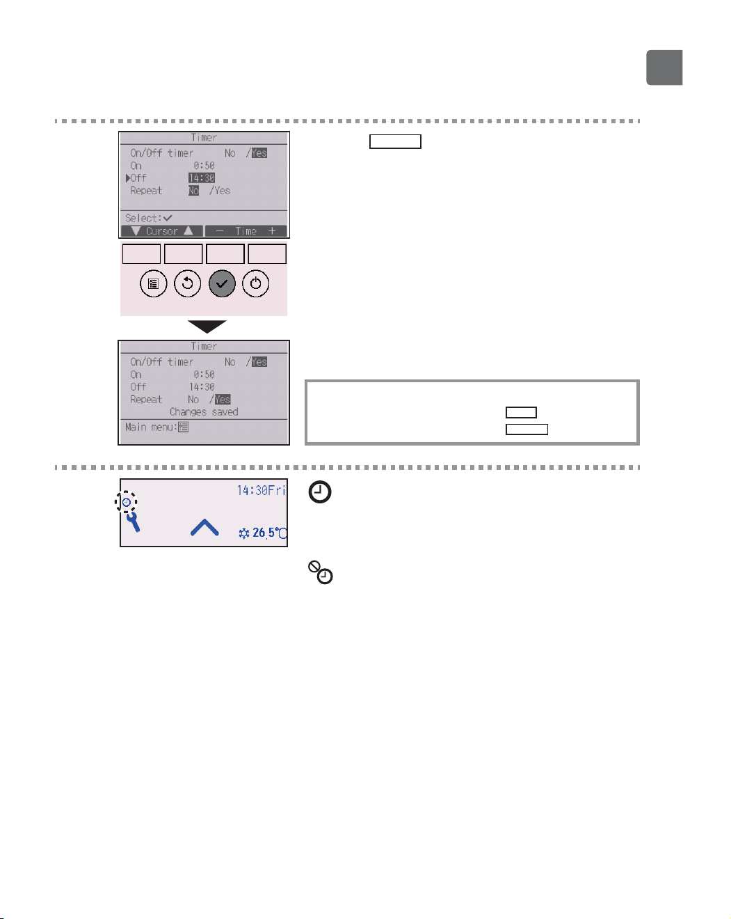
6
Press the
SELECT
button to save the settings.
A confirmation screen will appear.
Navigating through the screens
To go back to the Main menu ...........
MENU
button
To return to the previous screen
.......
RETURN
button
will appear on the Status display and the Main
display in the Full mode when the On/Off timer is
enabled.
appears when the timer is disabled by the
centralized control system.
32
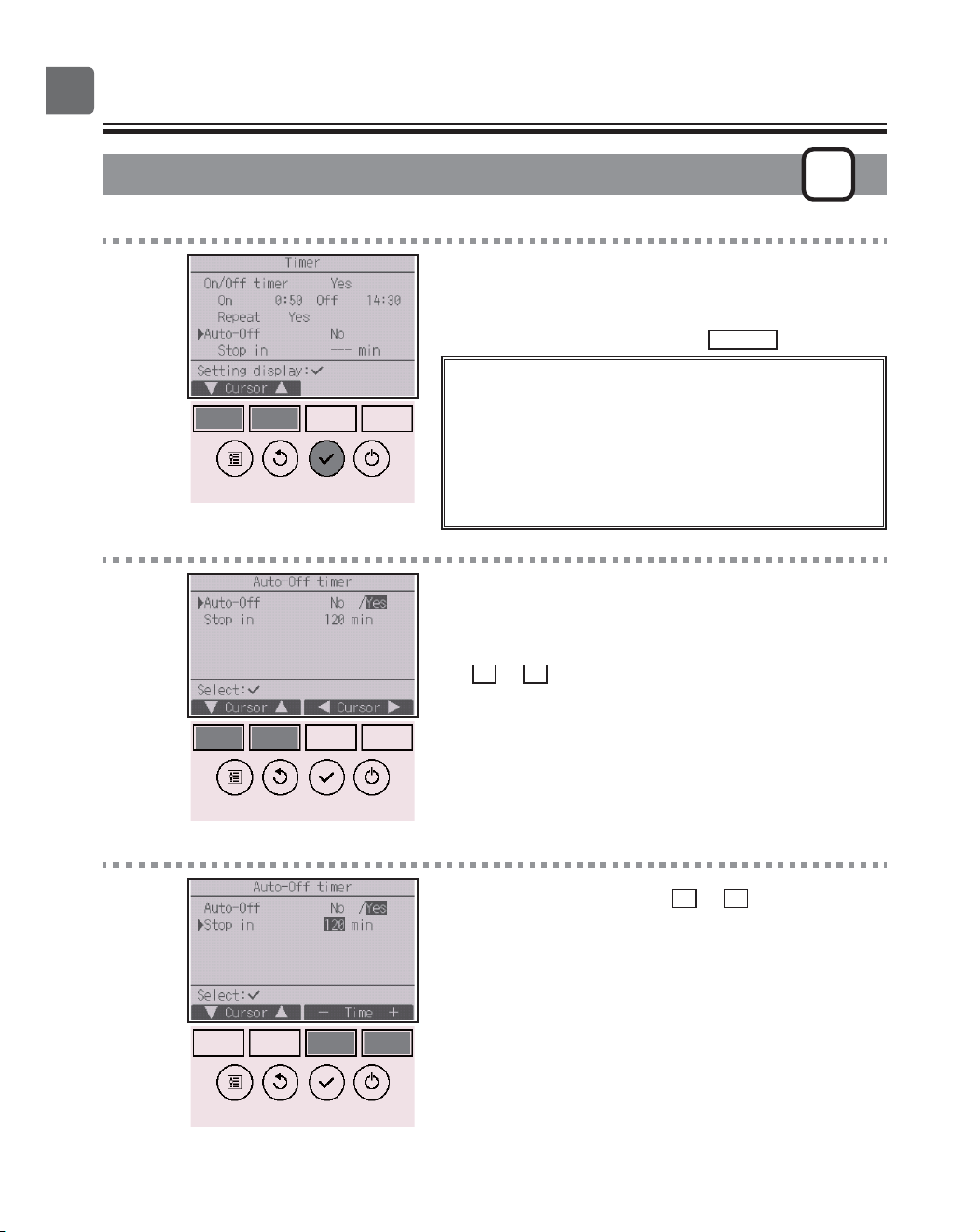
Function settings
Timer (Auto-Off timer)
P
Button operation
1
Bring up the Timer setting screen.
(Refer to page 29.)
Select “Auto-Off”, and press the
SELECT
button.
The Auto-Off timer will not work in the following
cases:
when Auto-Off timer is disabled, during an error, during
check (in the service menu), during test run, during
remote controller diagnosis, during function setting,
when the system is centrally controlled (when On/Off
operation or timer operation from local controller is
prohibited).
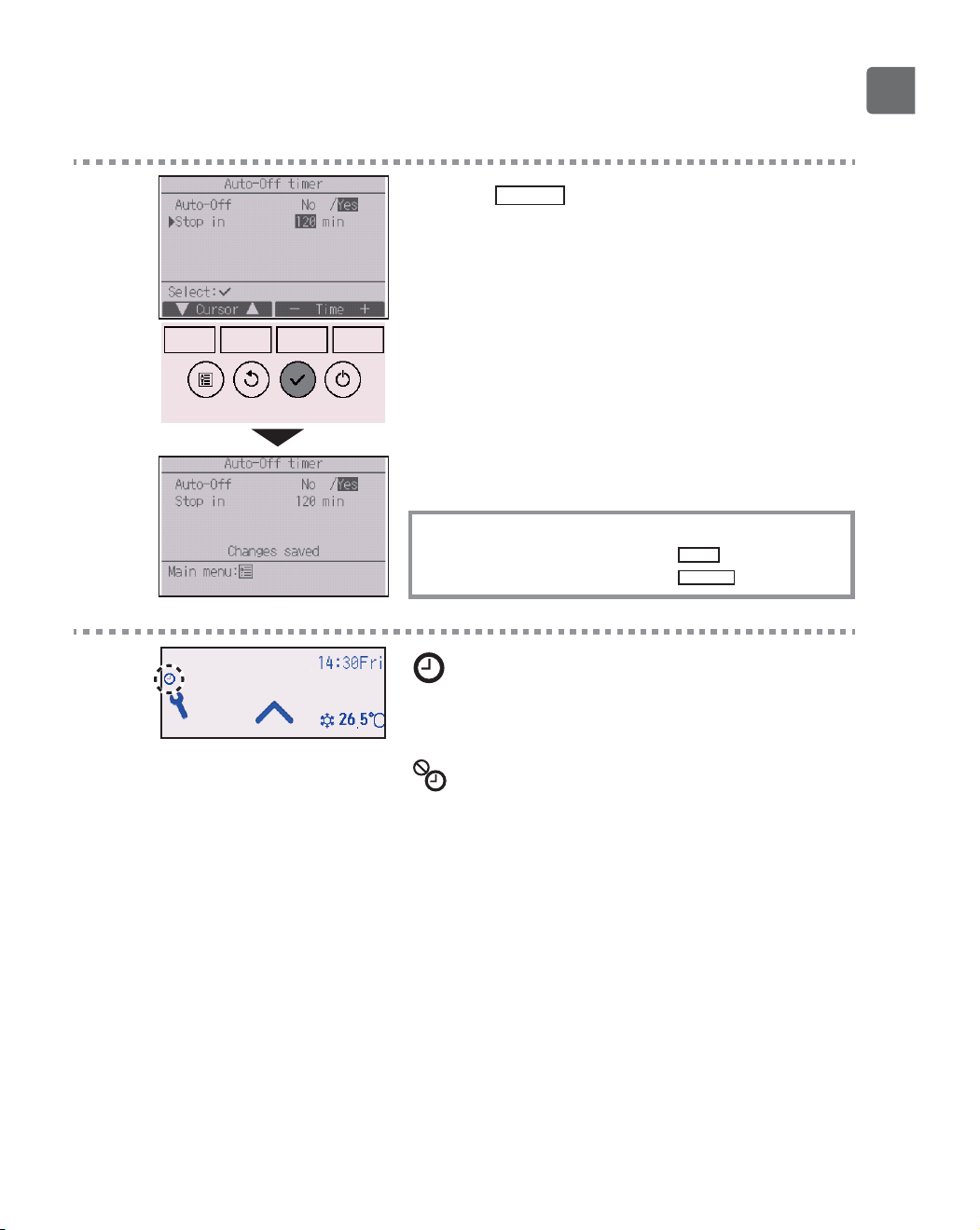
2
The current settings will appear.
Move the cursor to “Auto-Off” or “Stop in --- min” with
the
F1
or
F2
button.
3
Change the setting with the
F3
or
F4
button.
•
Auto-Off: No (disable)/Yes (enable)
•
Stop in --- min: Timer setting (The settable range is 30 to
240 minutes in 10-minute increments.)
33
4
Press the
SELECT
button to save the settings.
A confirmation screen will appear.
Navigating through the screens
To go back to the Main menu ...........
MENU
button
To return to the previous screen
.......
RETURN
button
will appear on the Status display and the Main
display in the Full mode when the Auto-Off timer is
enabled.
appears when the timer is disabled by the
centralized control system.
34
Function settings
Weekly timer
P
Button operation
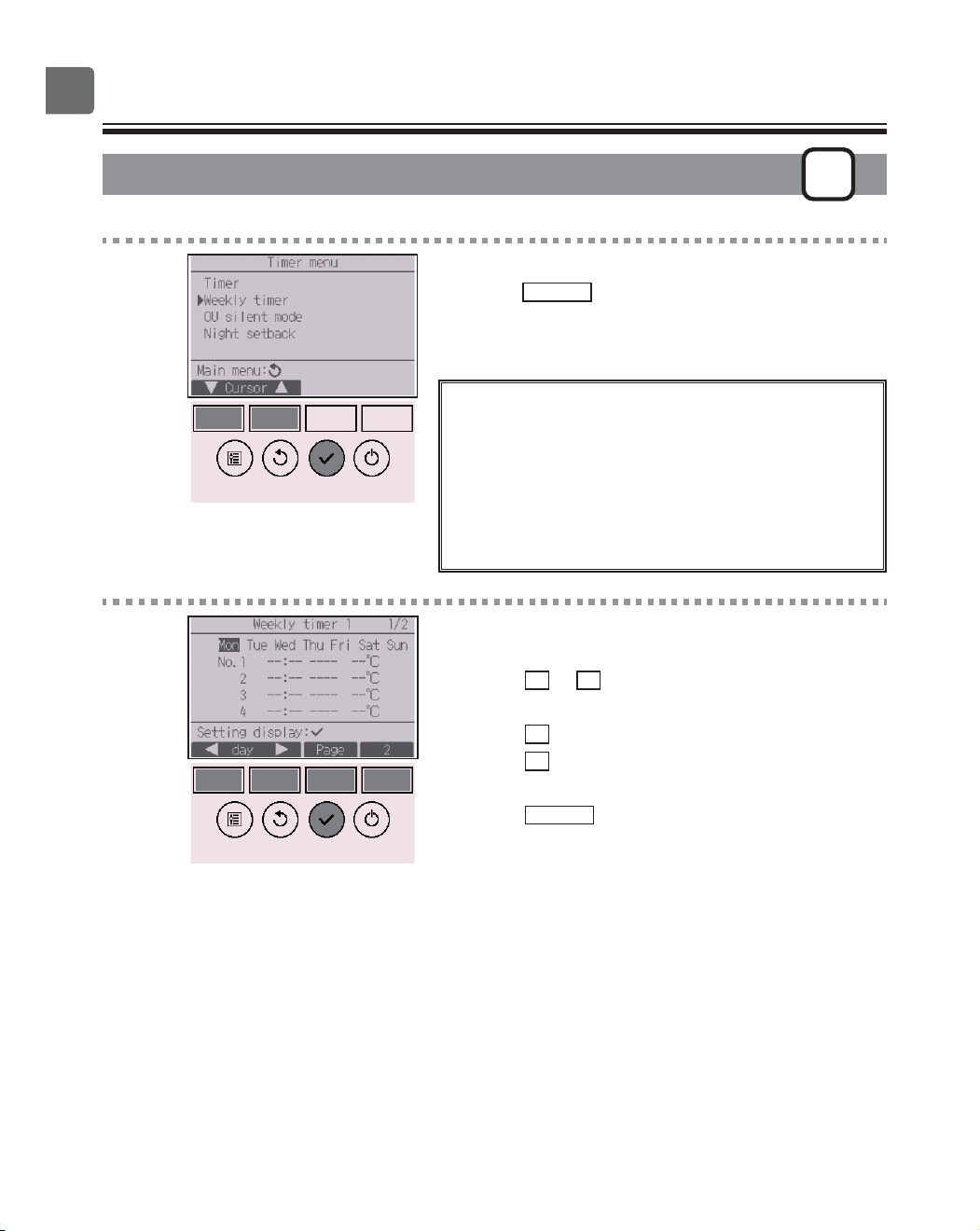
1
Select “Weekly timer” from the Timer menu, and
press the
SELECT
button.
The Weekly timer will not work in the following
cases:
when the On/Off timer is enabled, when the weekly
timer is disabled, during an error, during check (in the
service menu), during test run, during remote controller
diagnosis, when the clock is not set, during function
setting, when the system is centrally controlled (On/Off
operation, temperature setting, or timer operation from
local remote controller is prohibited).
2
The current settings will appear.
Press the
F1
or
F2
button to see the settings for
each day of the week.
Press the
F3
button to see patterns 5 through 8.
Press the
F4
button to display the status of Setting 2.
Press the
SELECT
button to go to the setting screen.
35
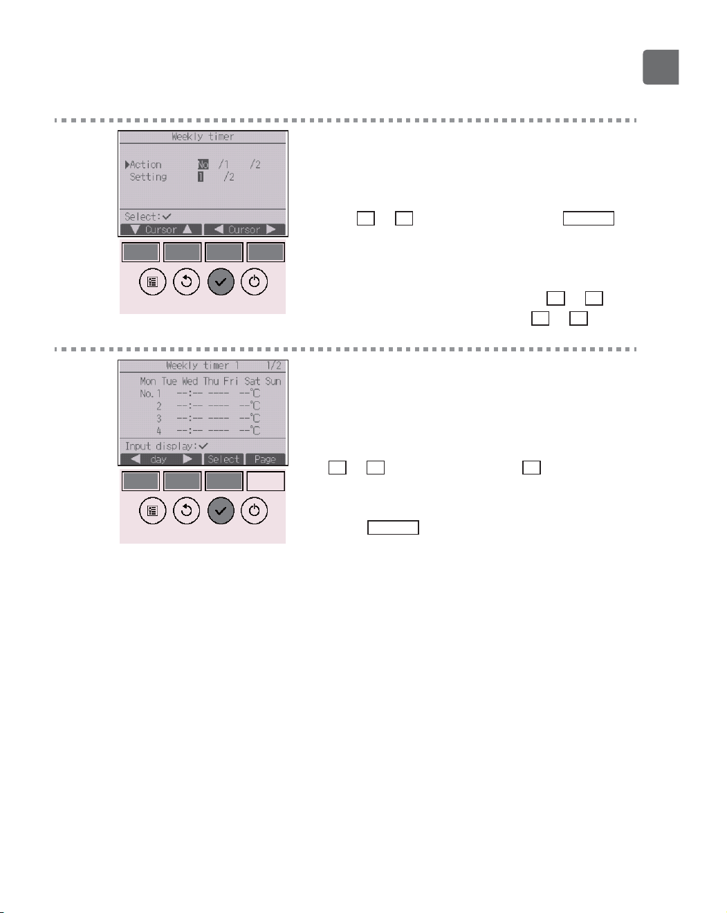
3
The weekly timer settings screen will appear.
In the “Action” setting, select “1” to enable the timer
setting 1, or select “2” to enable the timer setting 2
with the
F3
or
F4
button. Then, press the
SELECT
button.
To check the setting contents of the timer setting 1 or
2, move the cursor to “Setting” with the
F1
or
F2
button, and select “1” or “2” with the
F3
or
F4
button.
4
The weekly timer setting screen will appear and the
current settings will be displayed.
Up to eight operation patterns can be set for each
day.
Move the cursor to the desired day of the week with
the
F1
or
F2
button, and press the
F3
button to
select it. (Multiple days can be selected.)
Press the
SELECT
button.
36
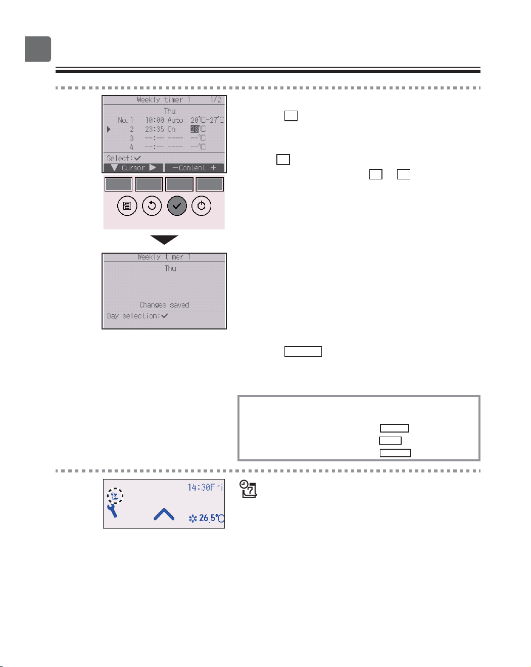
Function settings
5
Operation pattern setting screen will appear.
Press the
F1
button to move the cursor to the desired
pattern number.
Move the cursor to the time, On/Off, or temperature
with the
F2
button.
Change the settings with the
F3
or
F4
button.
•
Time: settable in 5-minute increments
*
Press and hold the button to rapidly advance the
numbers.
•
On/Off/Auto: Selectable settings depend on the model of
connected indoor unit. (When an Auto pattern is executed,
the system will operate in the Auto (dual set point) mode.)
•
Temperature: The settable temperature range depends on
the connected indoor units. (1ºC increments)
When the Auto (dual set point) mode is selected, two
preset temperatures can be set. If an operation pattern
with a single preset temperature setting is executed during
the Auto (dual set point) mode, its setting will be used as
the cooling temperature setting in the Cool mode.
Press the
SELECT
button to save the settings.
A confirmation screen will appear.
Navigating through the screens
To go back to the setting change/day of the week selection
screen .............................................
SELECT
button
To go back to the Main menu .........
MENU
button
To return to the previous screen .....
RETURN
button
will appear on the Status display and the Main
display in the Full mode when the weekly timer
setting for the current day exists.
The icon will not appear while the On/Off timer is
enabled or the system is under centralized control
(Timer operation from local remote controller is
prohibited).
37
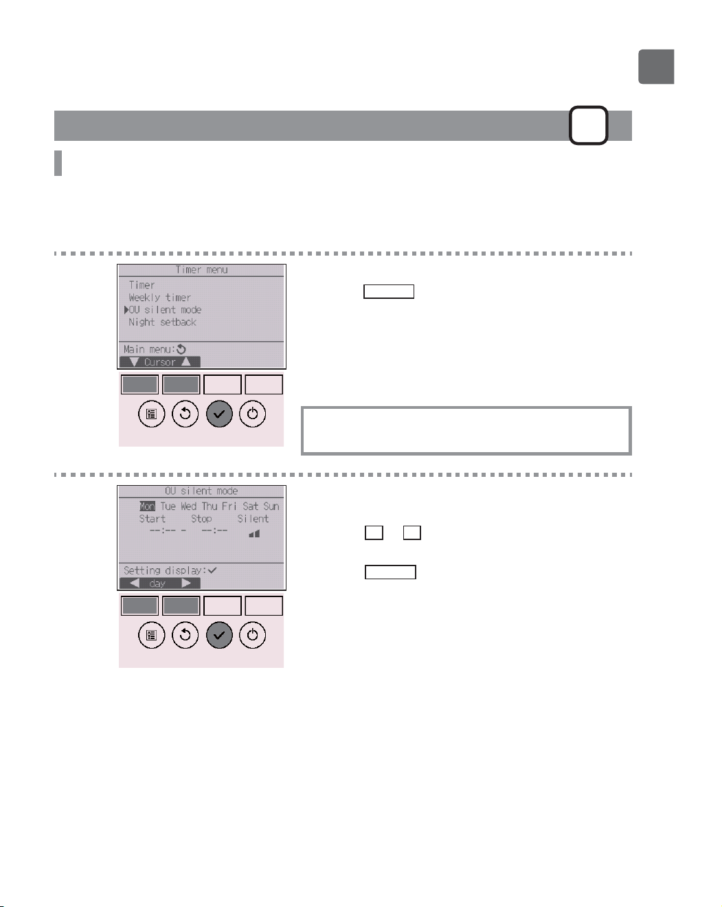
OU silent mode
P
Function description
This function allows the user to set the time periods in which priority is given to quiet operation of
outdoor units over temperature control. Set the start and stop times each day of the week for the quiet
operation. Select the desired silent level from “Middle” and “Quiet”.
Button operation
1
Select “OU silent mode” from the Timer menu, and
press the
SELECT
button.
“OU silent mode” function is available only on the
models that support the function.
2
The current settings will appear.
Press the
F1
or
F2
button to see the settings for
each day of the week.
Press the
SELECT
button to go to the setting screen.
38
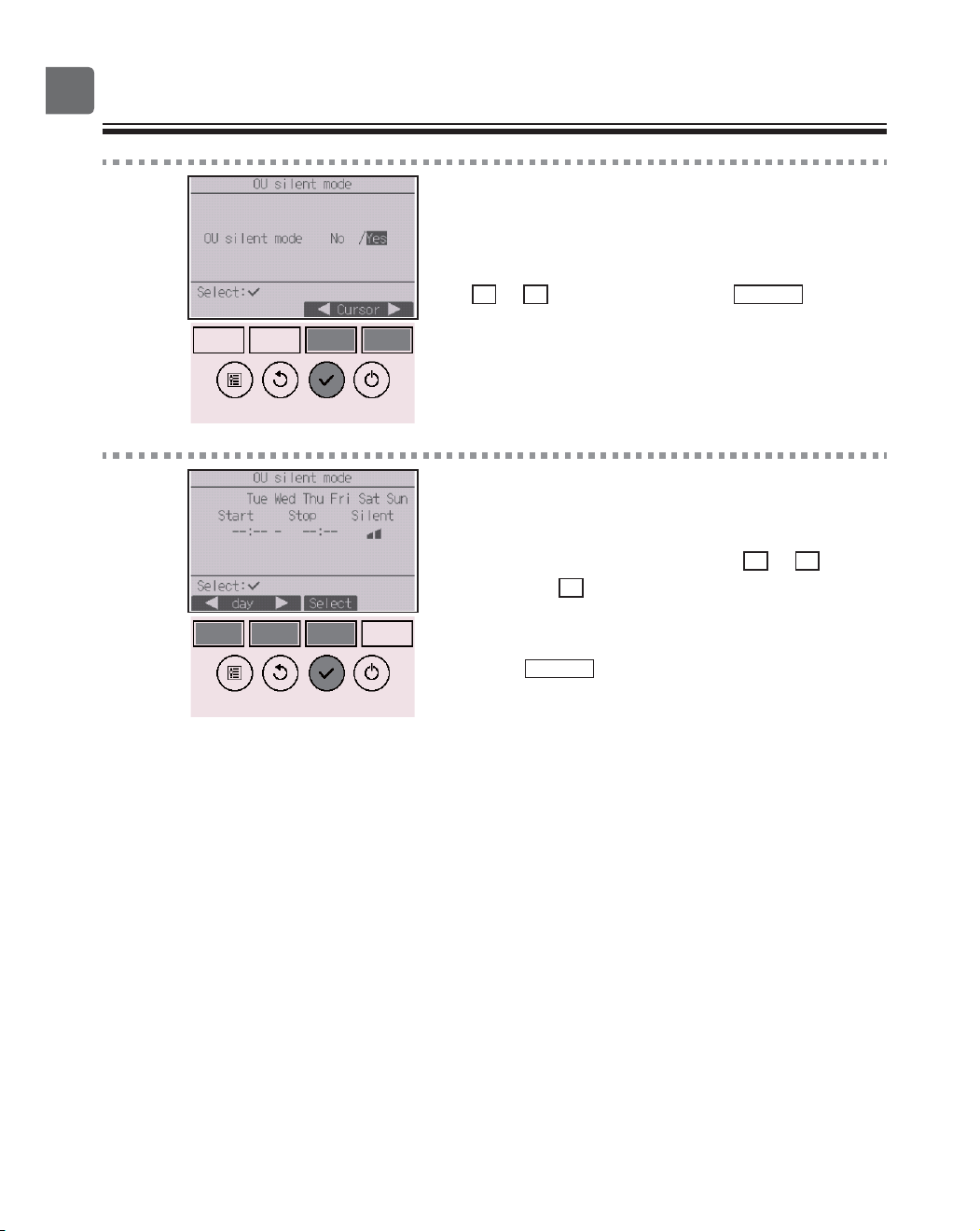
Function settings
3
The screen to enable (Yes) and disable (No) the
silent mode will appear.
To enable this setting, move the cursor to “Yes” with
the
F3
or
F4
button, and press the
SELECT
button .
4
The OU silent mode setting screen will appear.
To make or change the setting, move the cursor to
the desired day of the week with the
F1
or
F2
button,
and press the
F3
button to select it. (Multiple days
can be selected.)
Press the
SELECT
button.
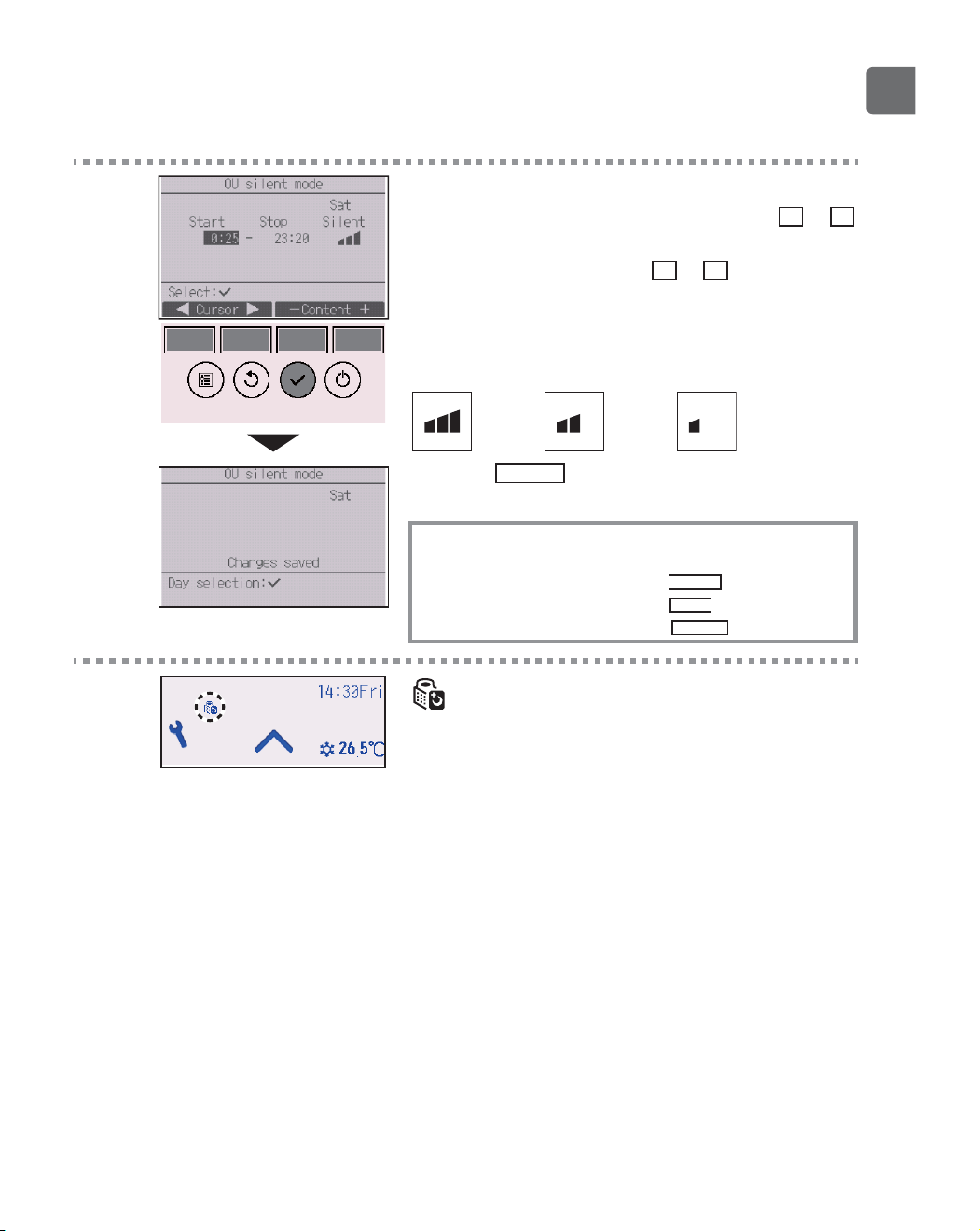
39
5
The setting screen will appear.
Move the cursor to the desired item with the
F1
or
F2
button out of Start time, Stop time, or Silent level.
Change the settings with the
F3
or
F4
button.
•
Start/Stop time: settable in 5-minute increments
*
Press and hold the button to rapidly advance the
numbers.
•
Silent level: Normal, Middle, Quiet
Normal
Middle Quiet
Press the
SELECT
button to save the settings. A
confirmation screen will appear.
Navigating through the screens
To go back to the setting change/day of the week selection
screen ............................................
SELECT
button
To go back to the Main menu .........
MENU
button
To return to the previous screen .....
RETURN
button
will appear on the Status display and the Main
display in the Full mode during the OU silent mode.
40
Function settings
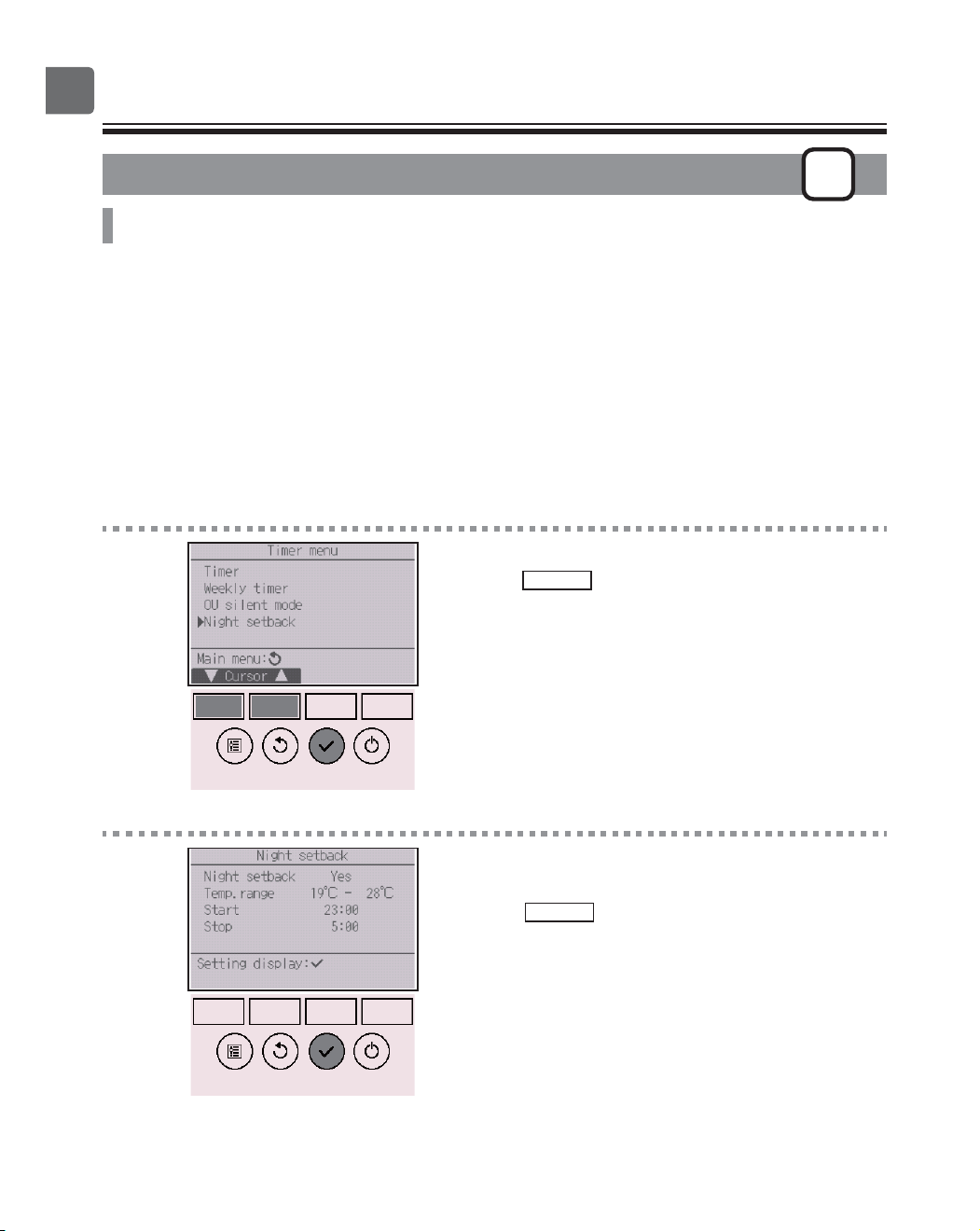
Night setback
P
Function description
This control starts heating operation when the control object group is stopped and the room
temperature drops below the preset lower limit temperature. Also, this control starts cooling operation
when the control object group is stopped and the room temperature rises above the preset upper limit
temperature.
The Night setback function is not available if the operation and the temperature setting are performed
from the remote controller.
If the room temperature is measured by the air-conditioner’s suction temperature sensor, the accurate
temperature may not be obtained when the air-conditioner is inactive or when the air is not clean. In
this case, switch the sensor to a remote sensor (PAC-SE40TSA/PAC-SE41TS-E) or a remote control
sensor.
Button operation
1
Select “Night setback” from the Timer menu, and
press the
SELECT
button.
2
The current settings will appear.
Press the
SELECT
button to go to the setting screen.
41
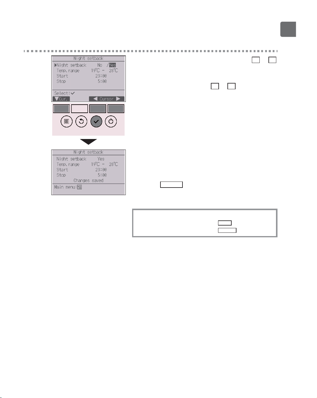
3
Move the cursor to the desired item with the
F1
or
F2
button out of Night setback No (disable)/Yes (enable),
Temp. range, Start time, or Stop time.
Change the settings with the
F3
or
F4
button.
•
Temp. range: The lower limit temperature (for heating
operation) and the upper limit temperature
(for cooling operation) can be set. The
temperature difference between the lower
and upper limits must be 4ºC (8ºF) or more.
The settable temperature range varies
depending on the connected indoor units.
*
1ºC increments
•
Start/Stop time: settable in 5-minute increments
*
Press and hold the button to rapidly advance the
numbers.
Press the
SELECT
button to save the settings.
A confirmation screen will appear.
Navigating through the screens
To go back to the Main menu ..........
MENU
button
To return to the previous screen
......
RETURN
button
42
Function settings
will appear on the Status display and the Main
display in the Full mode when the Night setback
function is enabled.
appears when the timer is disabled by the
centralized control system.
The Night setback will not work in the following
cases:
when the unit is in operation, when the Night setback
function is disabled, during an error, during check (in
the service menu), during test run, during remote
controller diagnosis, when the clock is not set, during
function setting, when the system is centrally controlled
(On/Off operation, temperature setting, or timer
operation from local remote controller is prohibited).
43
Restriction
P
Setting the temperature range restriction
Button operation
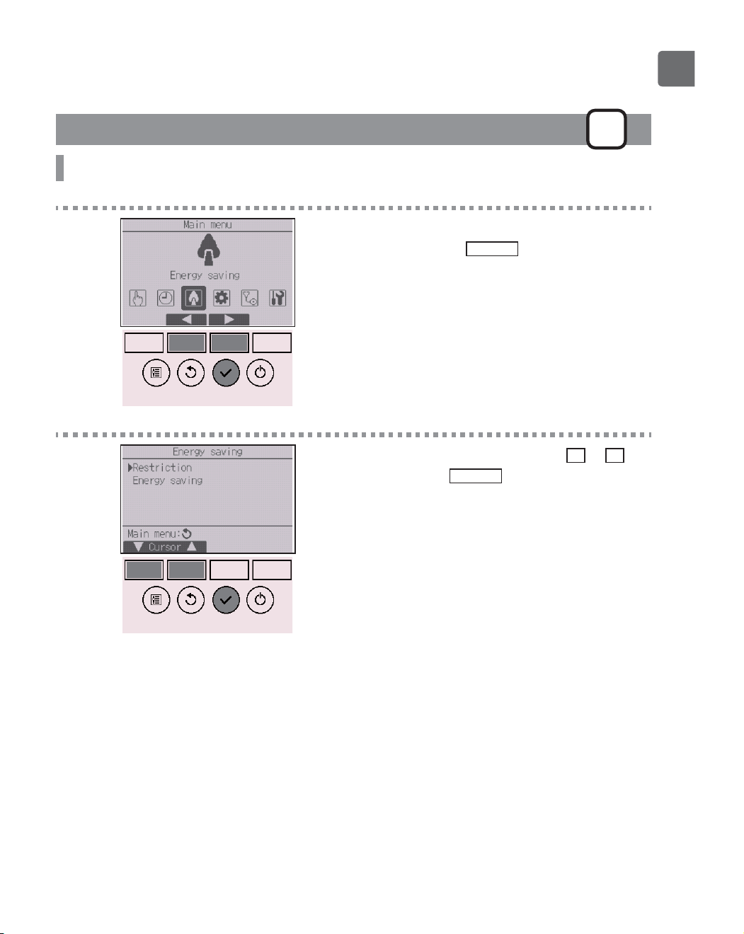
1
Select “Energy saving” from the Main menu (refer to
page 24), and press the
SELECT
button.
2
Move the cursor to “Restriction” with the
F1
or
F2
button, and press the
SELECT
button.
44
Function settings
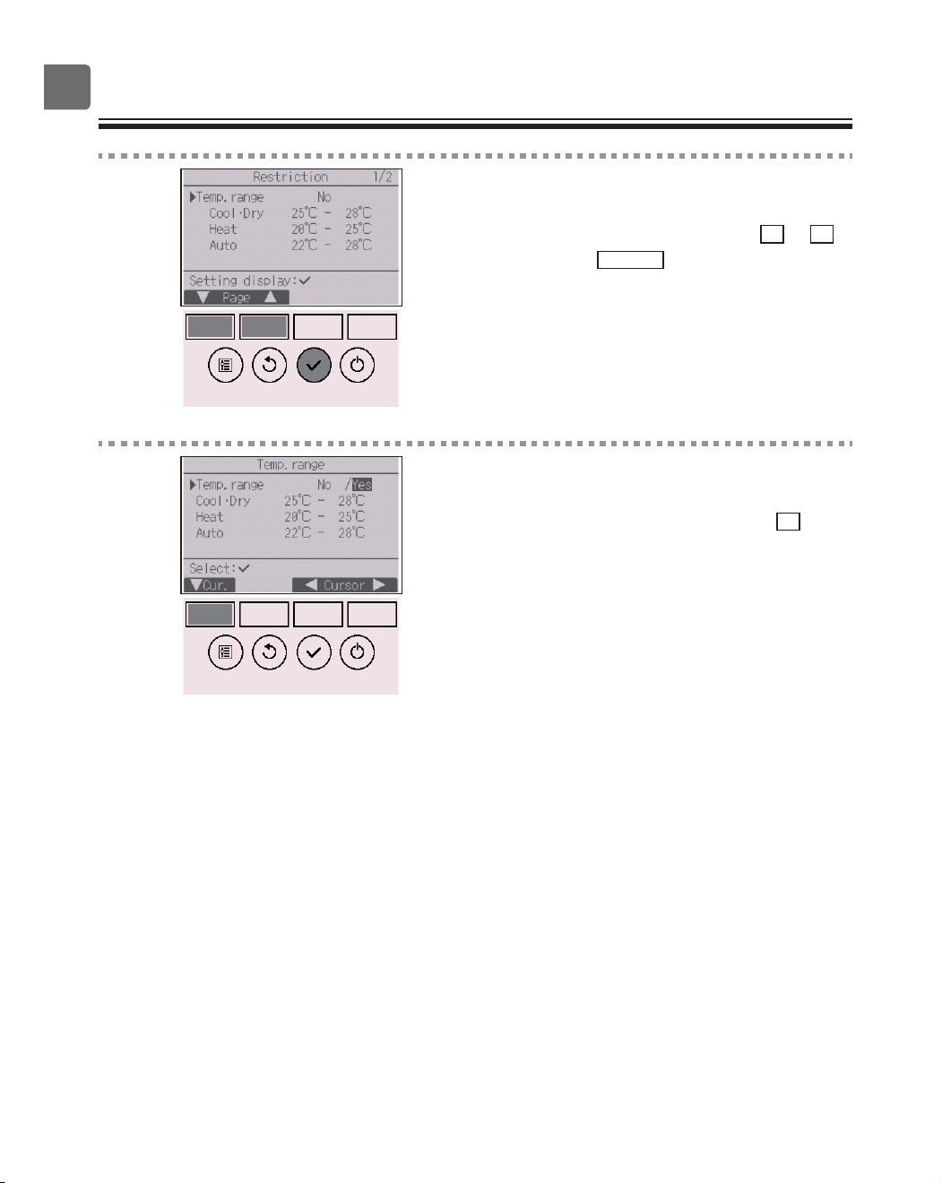
3
The current settings will appear.
Move the cursor to “Temp. range” with the
F1
or
F2
button, and press the
SELECT
button.
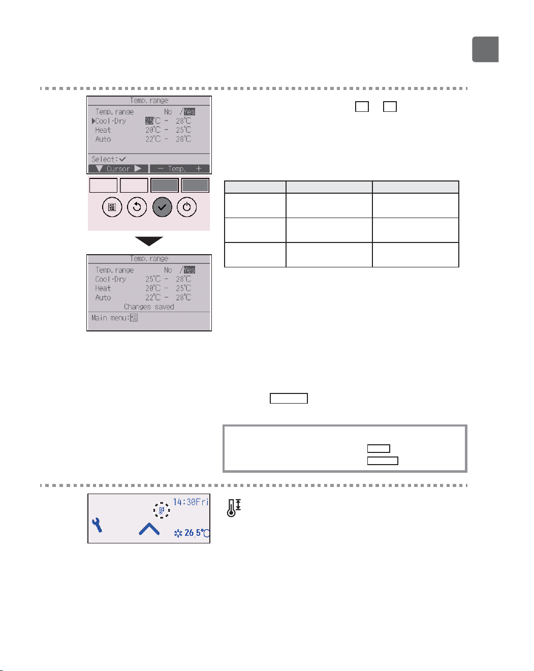
4
The screen to set the temperature range will appear.
Move the cursor to the desired item with the
F1
EXWWRQRXWRI³7HPSUDQJH´³&RRO'U\´³+HDW´RU
“Auto.”
45
5
Change the settings with the
F3
or
F4
button.
•
Temp. range: No (unrestricted) or Yes (restricted)
•
&RRO'U\8SSHUDQGORZHUOLPLWWHPSHUDWXUH&LQFUHPHQWV
•
Heat: Upper and lower limit temperature (1ºC increments)
•
Auto: Upper and lower limit temperature (1ºC increments)
Temperature setting ranges
Mode Lower limit Upper limit
&RRO'U\
*1
*3
19 ~ 30ºC
(67 ~ 87ºF)
30 ~ 19ºC
(87 ~ 67ºF)
Heat
*2
*3
17 ~ 28ºC
(63 ~ 83ºF)
28 ~ 17ºC
(83 ~ 63ºF)
Auto
*4
19 ~ 28ºC
(67 ~ 83ºF)
28 ~ 19ºC
(83 ~ 67ºF)
*
The settable range varies depending on the connected unit.
*1
Temperature ranges for the Cool, Dry, and Auto (dual set point)
modes can be set.
*2
Temperature ranges for the Heat and Auto (dual set point)
modes can be set.
*3
Temperature ranges for the Heat, Cool, and Dry modes must
meet the conditions below:
8SSHUOLPLWIRUFRROLQJXSSHUOLPLWIRUKHDWLQJ0LQLPXP
temperature difference (varies with indoor unit model)
/RZHUOLPLWIRUFRROLQJORZHUOLPLWIRUKHDWLQJ0LQLPXP
temperature difference (varies with indoor unit model)
*4
Temperature range for the Auto (single set point) mode can be
set.
Press the
SELECT
button to save the settings.
A confirmation screen will appear.
Navigating through the screens
To go back to the Main menu ..........
MENU
button
To return to the previous screen
......
RETURN
button
will appear on the Status display and the Main
display in the Full mode when the temperature range
is restricted.
46
Function settings
@@@Restriction
P
Operation lock function
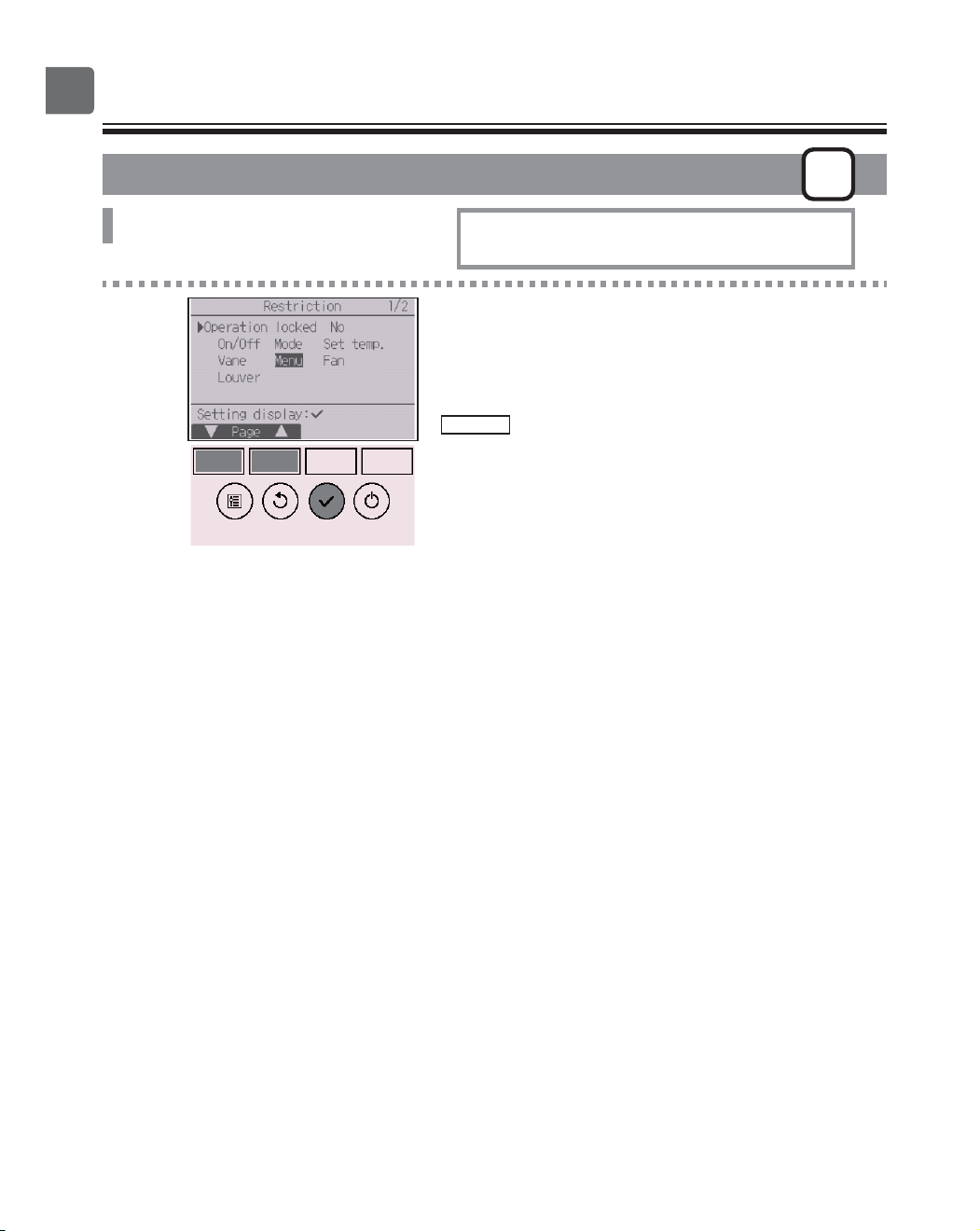
Button operation
1
Bring up the Restriction setting screen. (Refer to
page 43.)
Move the cursor to “Operation locked” and press the
SELECT
button.
To enable the operation lock function, set the
item “Operation locked” to “ Yes”.
47
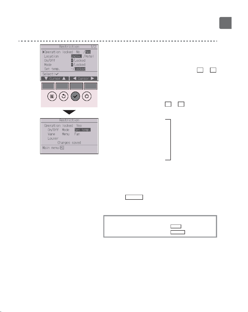
2
The screen to make the settings for the operation
lock function will appear.
Move the cursor to the desired item with the
F1
or
F2
button out of “Operation locked,” “Location,” “On/Off,”
“Mode,” “Set temp.,” “Menu,” “Fan,” “Louver,” or
“Vane.”
Change the settings with the
F3
or
F4
button.
•
Operation locked: No (disable)/Yes (enable)
•
Location: “Individual” or “Hotel”
•
On/Off: On/Off operation
•
Mode: Operation mode setting “-” / “Locked”
•
Set temp.: Preset temp. setting
•
Vane: Vane setting
•
Menu: Menu setting
•
Fan: Fan speed setting
•
Louver: Louver setting
When “Hotel” is selected for the “Location” setting,
the following operations will be locked automatically:
Mode, Vane, Menu, and Louver.
Press the
SELECT
button to save the settings.
A confirmation screen will appear.
Navigating through the screens
To go back to the Main menu ..........
MENU
button
To return to the previous screen
......
RETURN
button
48
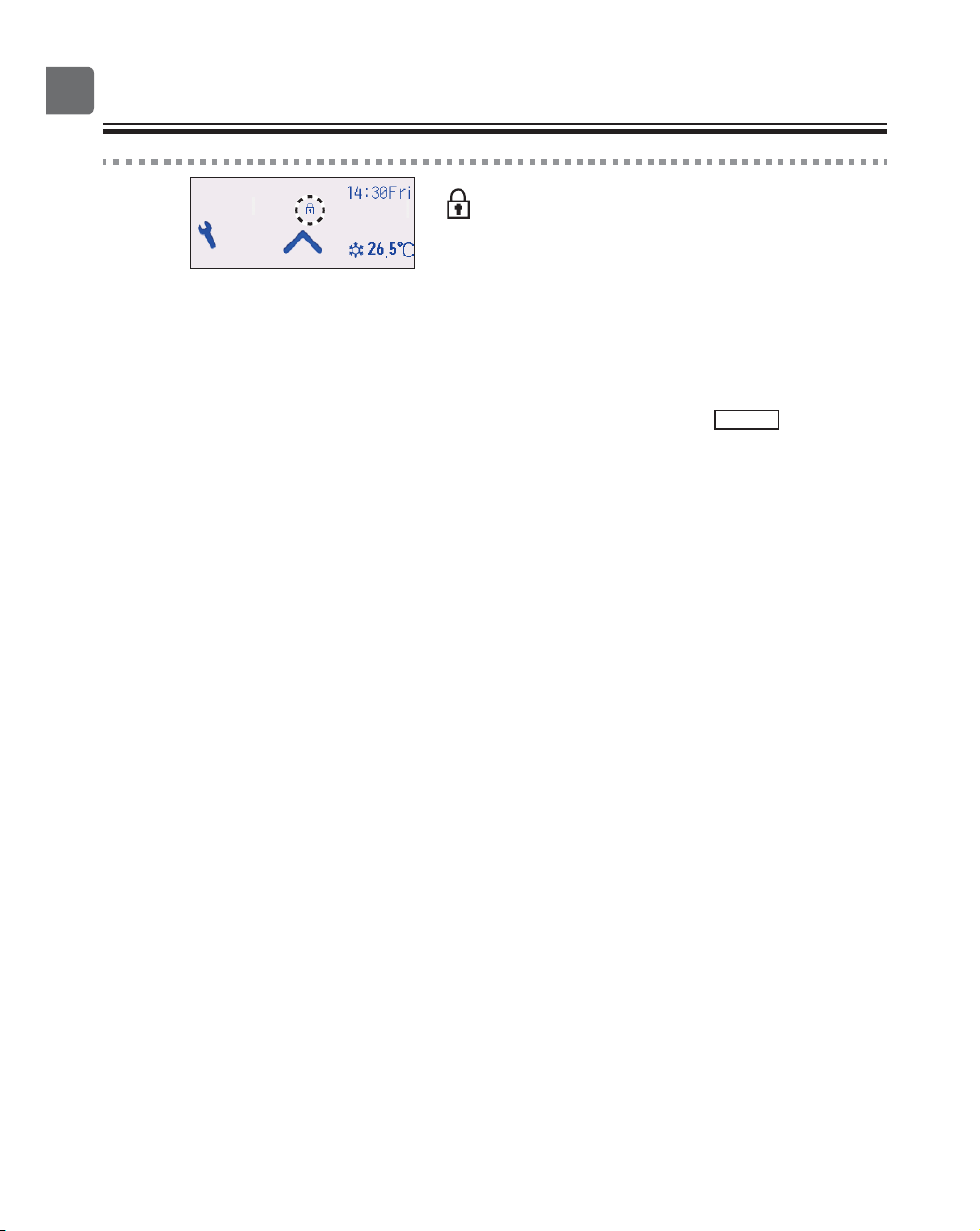
Function settings
will appear on the Status display and the Main
display in the Full mode when the operation lock
function setting is enabled.
Operation guide that corresponds to the locked
function will be suppressed.
To display the main menu while the menu setting is
being locked, press and hold the
Setting
button for
ten or more seconds. Enter the administrator’s
password on the password input screen.
49
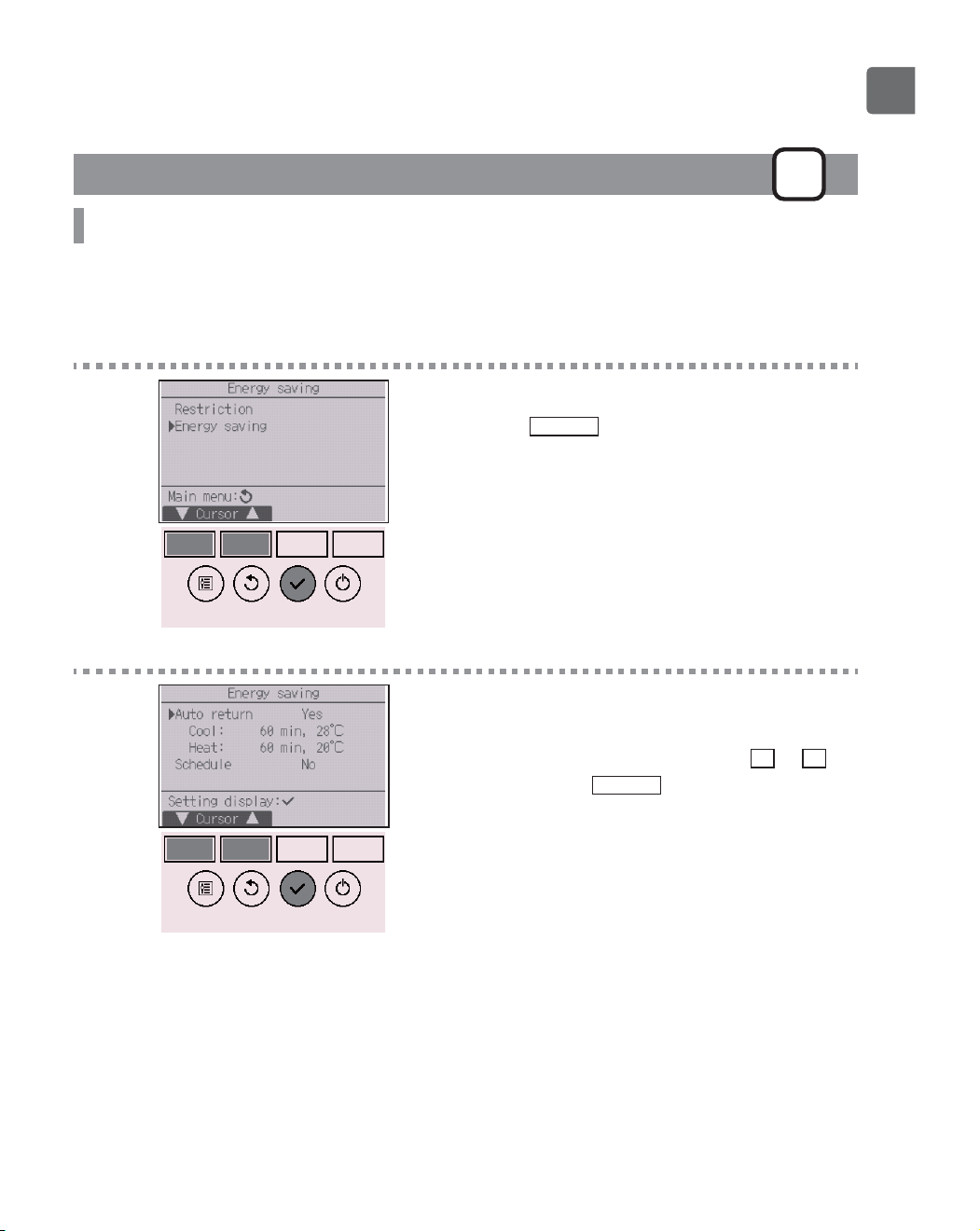
Energy saving
P
Automatic return to the preset temperature
After the Auto return function is enabled, when the operation mode change or ON/OFF operation is
performed from this remote controller, the set temperature automatically returns to the required
temperature regardless of the set time.
Button operation
1
Select “Energy saving” from the Energy saving menu,
and press the
SELECT
button.
2
The current settings will appear.
Move the cursor to “Auto return” with the
F1
or
F2
button, and press the
SELECT
button.
50
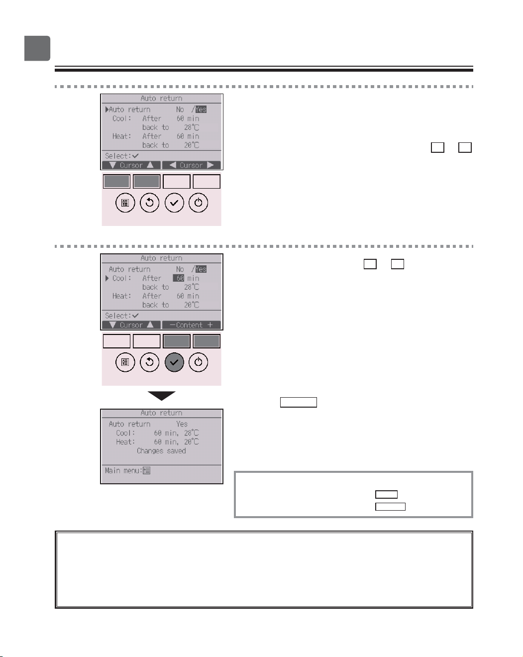
Function settings
3
The screen to make the settings for the automatic
return to the preset temperature will appear.
Move the cursor to the desired item with the
F1
or
F2
button out of “Auto return,” “Cool,” or “Heat.”
4
Change the settings with the
F3
or
F4
button.
•
Auto return: No (disable)/Yes (enable)
•
Cool: Timer setting range is 30 to 120 minutes in
10-minute increments.
Temperature setting range is 19 to 30ºC (67 to 87ºF)
(1ºC increments).
•
Heat: Timer setting range is 30 to 120 minutes in
10-minute increments.
Temperature setting range is 17 to 28ºC
(63 to 83ºF) (1ºC increments).
Press the
SELECT
button to save the settings. “Cool”
includes “Dry” and “Auto Cool” modes, and “Heat”
includes “Auto Heat” mode.
The screen to set the selected item will appear.
Navigating through the screens
To go back to the Main menu ..........
MENU
button
To return to the previous screen
......
RETURN
button
Timer or preset temperature settings will not be effective when the temperature range is
restricted and when the system is centrally controlled (when the temperature range
setting from local controller is prohibited). When the system is centrally controlled (when
timer operation from local remote controller is prohibited), only the timer setting will be
ineffective.
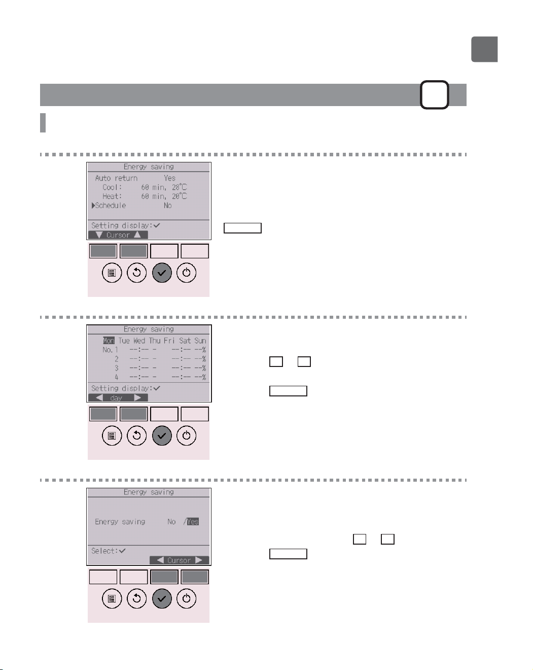
51
Energy saving
P
Setting the energy-saving operation schedule
Button operation
1
Bring up the “Energy saving” screen. (Refer to page
49.)
Move the cursor to “Schedule,” and press the
SELECT
button.
2
The screen to see the schedule will appear.
Press the
F1
or
F2
button to see the settings for
each day of the week.
Press the
SELECT
button to go to the setting screen.
3
The screen to enable (Yes)/disable (No) the energy-
saving operation schedule will appear.
Select “No” or “Yes” with the
F3
or
F4
button.
Press the
SELECT
button to go to the setting change/
day of the week selection screen.
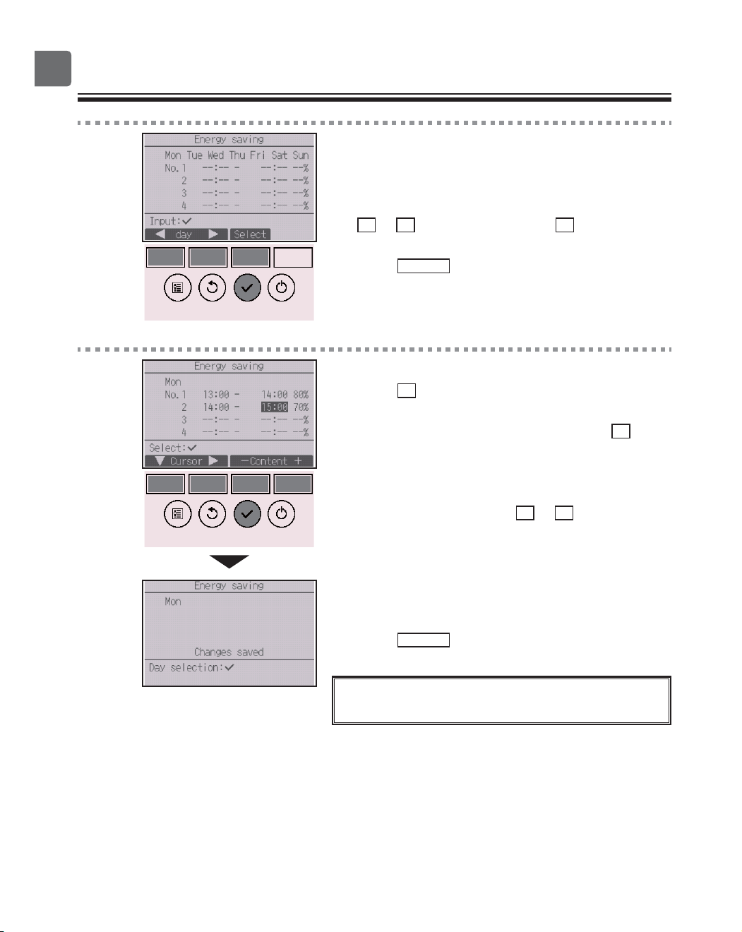
52
Function settings
4
The setting change/day of the week selection screen
will appear.
Up to four operation patterns can be set for each day.
Move the cursor to the desired day of the week with
the
F1
or
F2
button, and press the
F3
button to
select it. (Multiple days can be selected.)
Press the
SELECT
button to go to the pattern setting
screen.
5
The pattern setting screen will appear.
Press the
F1
button to move the cursor to the desired
pattern number.
Move the cursor to the desired item with the
F2
button out of the start time, stop time, and energy-
saving rate (arranged in this order from the left).
Change the settings with the
F3
or
F4
button.
•
Start/Stop time: settable in 5-minute increments
*
Press and hold the button to rapidly advance the
numbers.
•
Energy-saving rate: The setting range is 0% and 50 to
90% in 10% increments.
Press the
SELECT
button to save the settings.
A confirmation screen will appear.
The lower the value, the greater the energy-saving
effect.
53
will appear on the Status display and the Main
display in the Full mode when the unit is operated in
the energy saving mode.
Navigating through the screens
To go back to the setting change/day of the week selection
screen ............................................
SELECT
button
To go back to the Main menu
..........
MENU
button
To return to the previous screen
......
RETURN
button
54
Function settings
Clock
P
Button operation
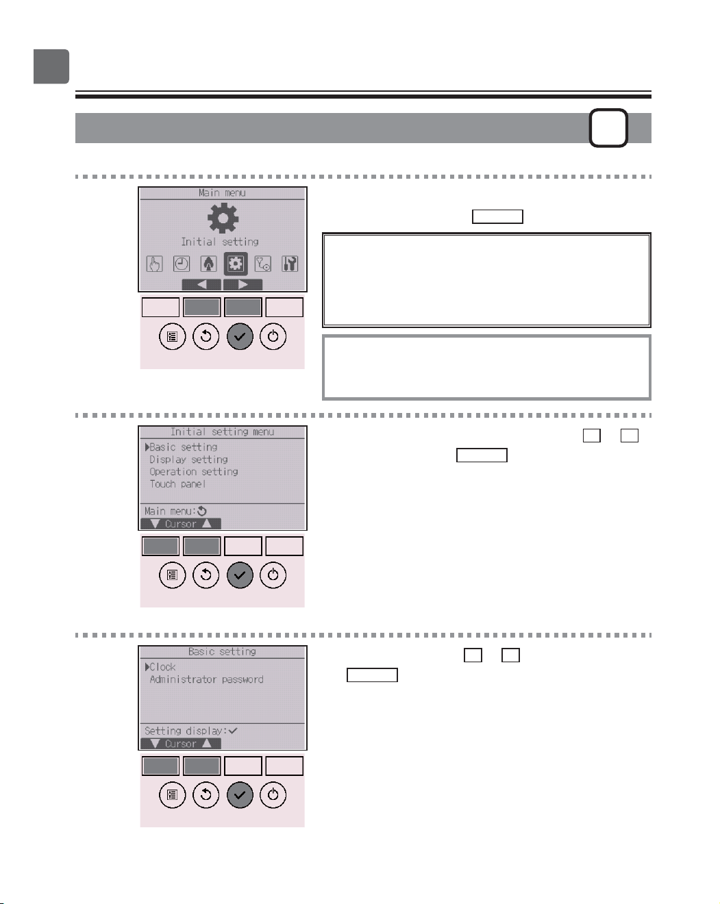
1
Select “Initial setting” from the Main menu (refer to
page 24), and press the
SELECT
button.
Clock setting is required before making the
following settings.
On/Off timer
OU silent mode
Night setback
Weekly timer
Energy saving
If a given system has no system controllers, the clock
time will not automatically be corrected.
In this case, periodically correct the clock time.
2
Move the cursor to “Basic setting” with the
F1
or
F2
button, and press the
SELECT
button.
3
Select “Clock” with the
F1
or
F2
button, and press
the
SELECT
button.
55
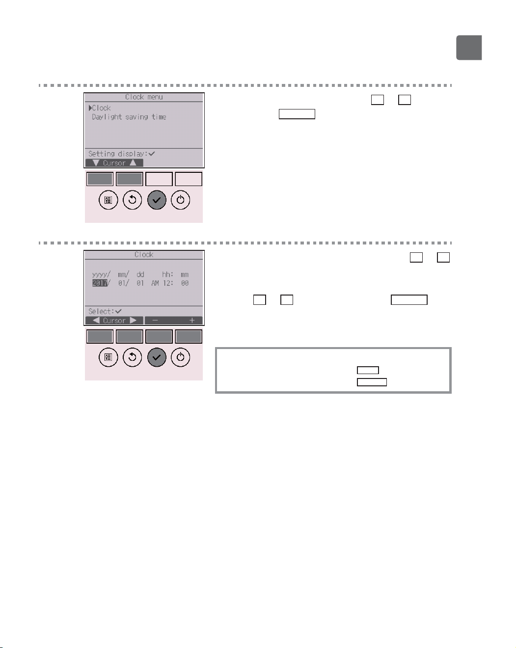
4
Move the cursor to “Clock” with the
F1
or
F2
button,
and press the
SELECT
button.
5
Move the cursor to the desired item with the
F1
or
F2
button out of year, month, date, hour, or minute.
Increase or decrease the value for the selected item
with the
F3
or
F4
button, and press the
SELECT
button.
A confirmation screen will appear.
Navigating through the screens
To go back to the Main menu ...........
MENU
button
To return to the previous screen
.......
RETURN
button
56
Function settings
Daylight saving time
P
Function description
The start/end time for daylight saving time can be set. The daylight saving time function will be
activated based on the setting contents.
•
If a given system has a system controller, disable this setting to keep the correct time.
•
At the beginning and the end of daylight saving time, the timer may go into action twice or not at
all.
•
This function will not work unless the clock has been set.
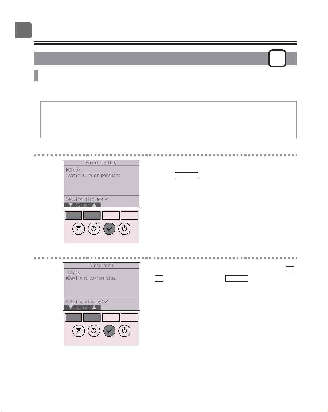
Button operation
1
Select “Clock” from the Basic setting menu, and
press the
SELECT
button.
2
Move the cursor to “Daylight saving time” with the
F1
or
F2
button, and press the
SELECT
button.
57
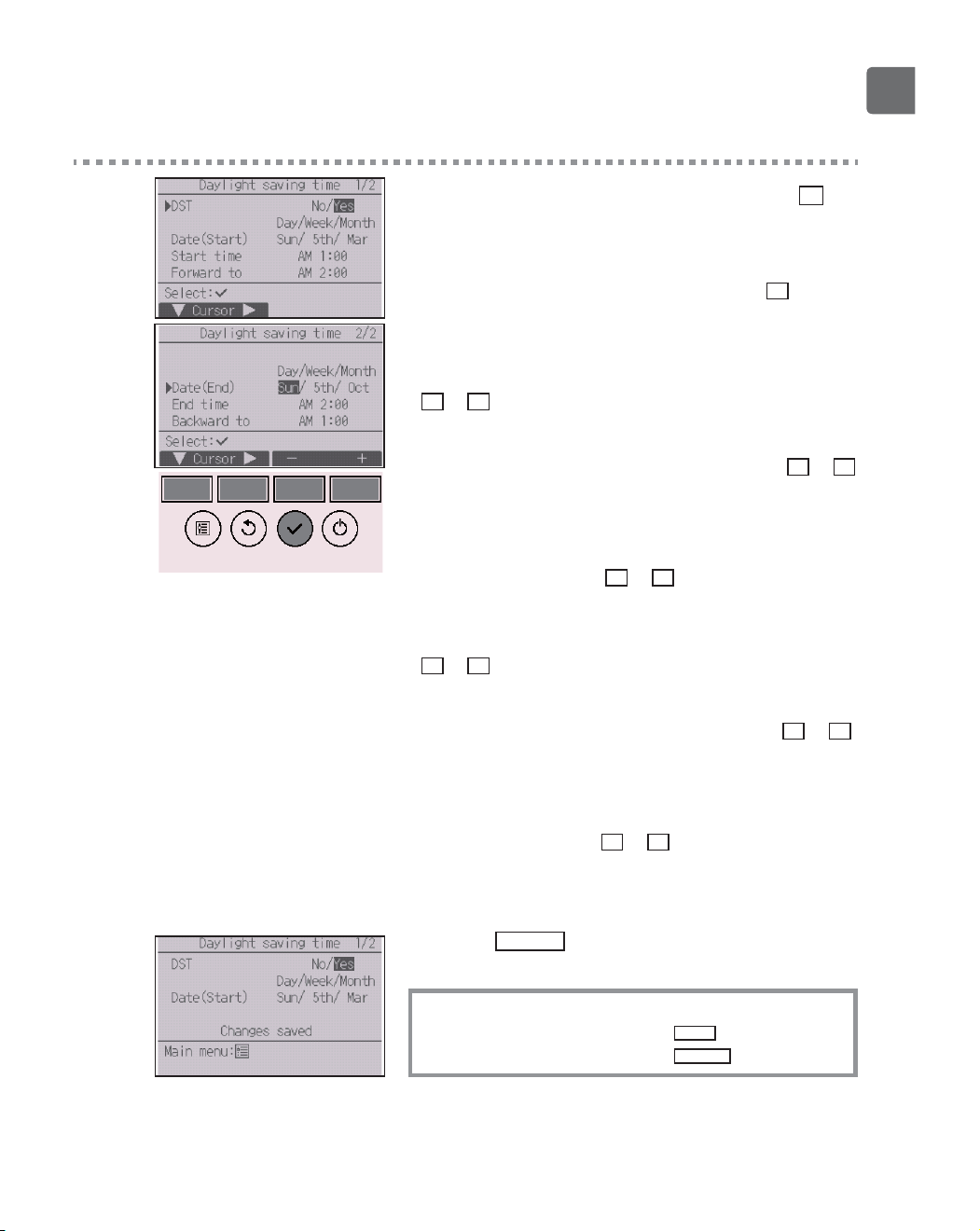
3
Move the cursor to the following items with the
F1
button to make the settings.
•
DST
Select “No” (disable) or “Yes” (enable) with the
F2
button.
The default setting is “No.”
•
Date(Start)
*1
Set the day of the week, week number, and month with the
F3
or
F4
button. The default setting is “Sun/5th/Mar.”
•
Start time
Set the start time for daylight saving time with the
F3
or
F4
button.
•
Forward to
Set the time when the clock is to be set forward to at the
start time above with the
F3
or
F4
button.
•
Date(End)
*1
(2nd page)
Set the day of the week, week number, and month with the
F3
or
F4
button. The default setting is “Sun/5th/Oct.”
•
End time (2nd page)
Set the end time for daylight saving time with the
F3
or
F4
button.
•
Backward to (2nd page)
Set the time when the clock is to be set backward to at the
end time above with the
F3
or
F4
button.
*1
If “5th” is selected for the week number and the 5th week does
not exist in the selected month of the year, the setting is
considered to be “4th.”
Press the
SELECT
button to save the settings.
A confirmation screen will appear.
Navigating through the screens
To go back to the Main menu ..........
MENU
button
To return to the previous screen
......
RETURN
button
58
Function settings
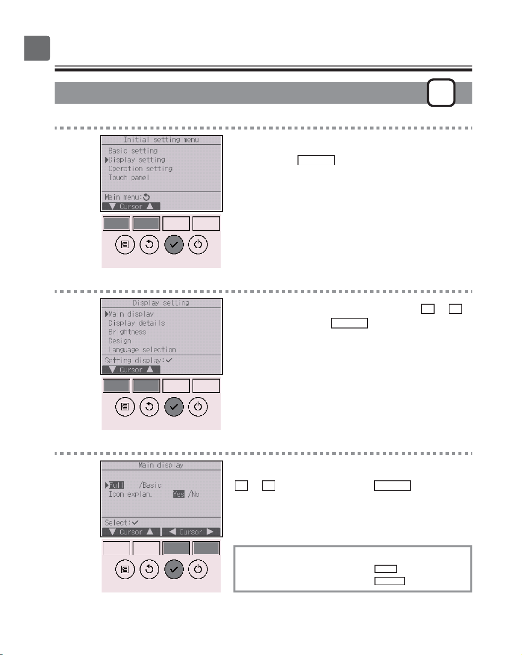
Main display
P
Button operation
1
Select “Display setting” from the Initial setting menu,
and press the
SELECT
button.
2
Move the cursor to “Main display” with the
F1
or
F2
button, and press the
SELECT
button.
3
Select “Full” or “Basic” (refer to page 10) with the
F3
or
F4
button, and press the
SELECT
button.
A confirmation screen will appear.
Navigating through the screens
To go back to the Main menu ..........
MENU
button
To return to the previous screen
......
RETURN
button
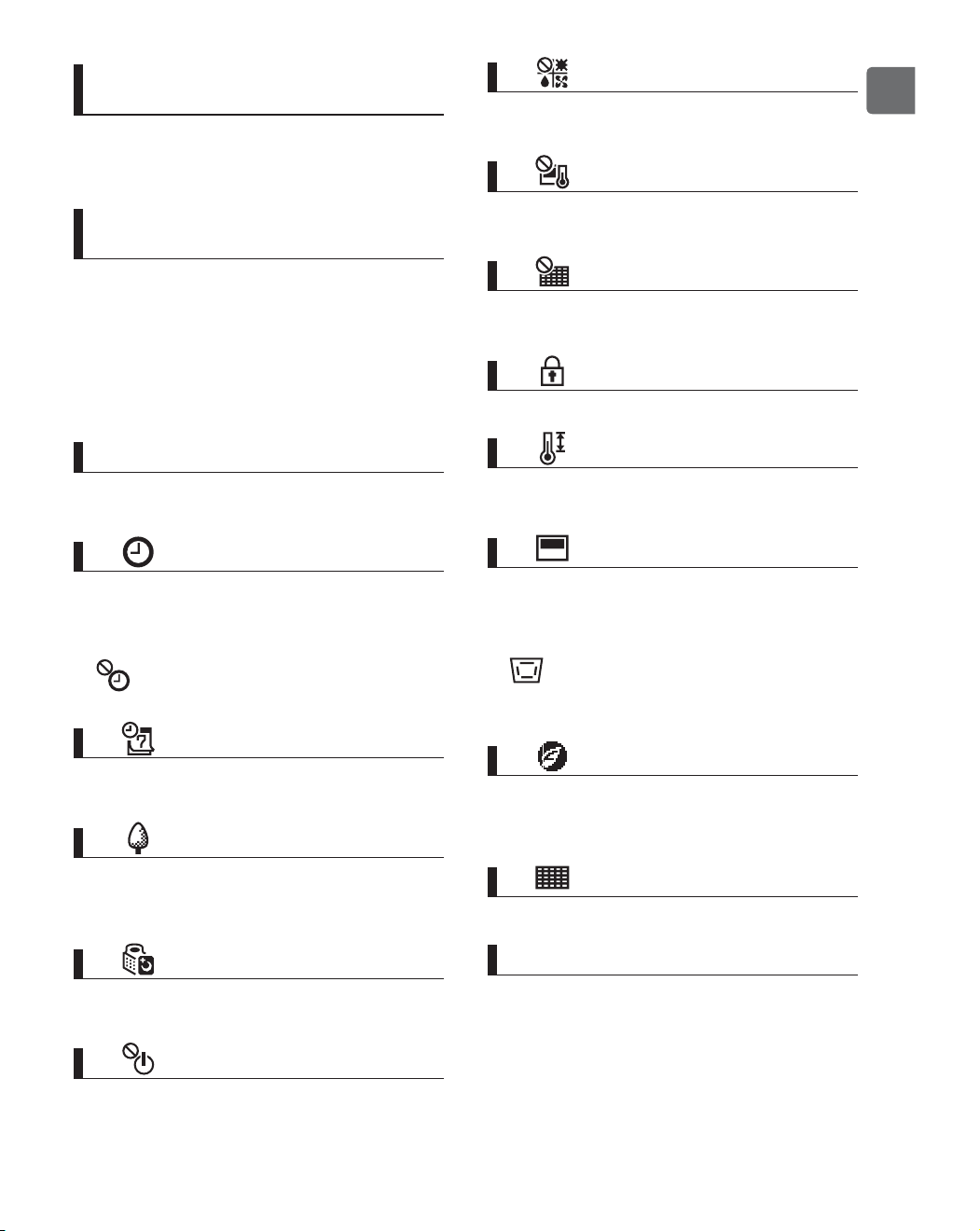
59
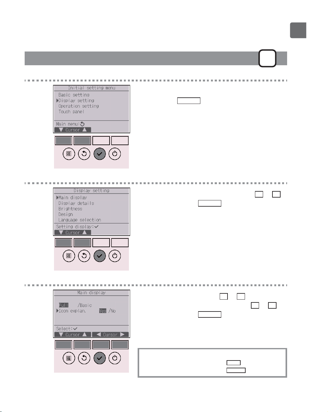
Icon explanation
P
Button operation
1
Select “Display setting” from the Initial setting menu,
and press the
SELECT
button.
2
Move the cursor to “Main display” with the
F1
or
F2
button, and press the
SELECT
button.
3
Select “Icon explan.” with the
F1
or
F2
button, select
the desired setting “Yes” or “No” with the
F3
or
F4
button, and press the
SELECT
button.
The default setting is “Yes”.
Navigating through the screens
To go back to the Main menu ..........
MENU
button
To return to the previous screen
......
RETURN
button
60
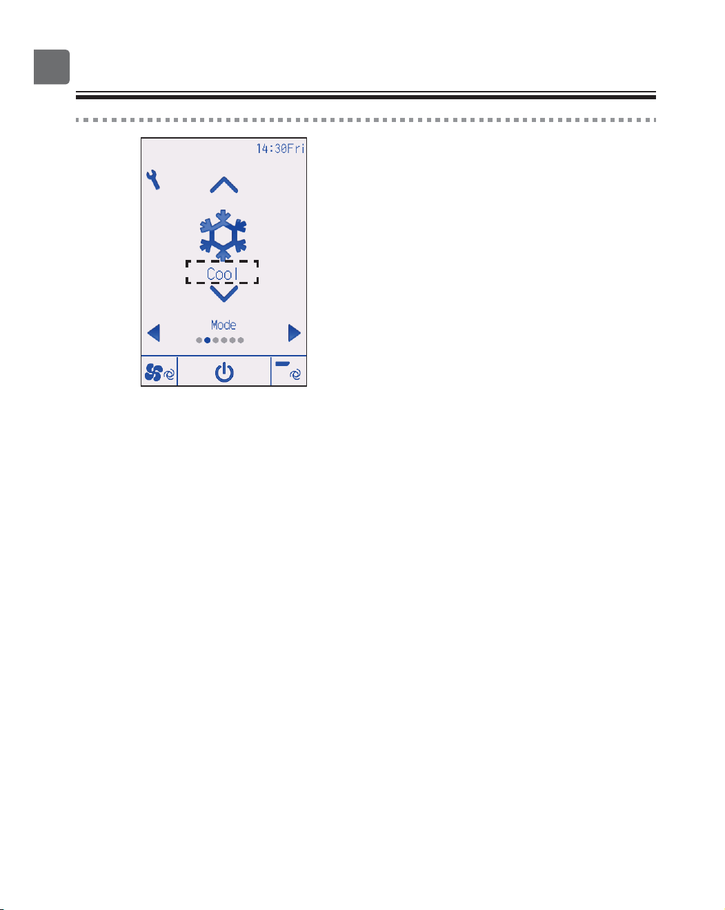
Function settings
4
When “Yes” is selected, the explanation of the icon of
the setting item will appear as shown at left.
61
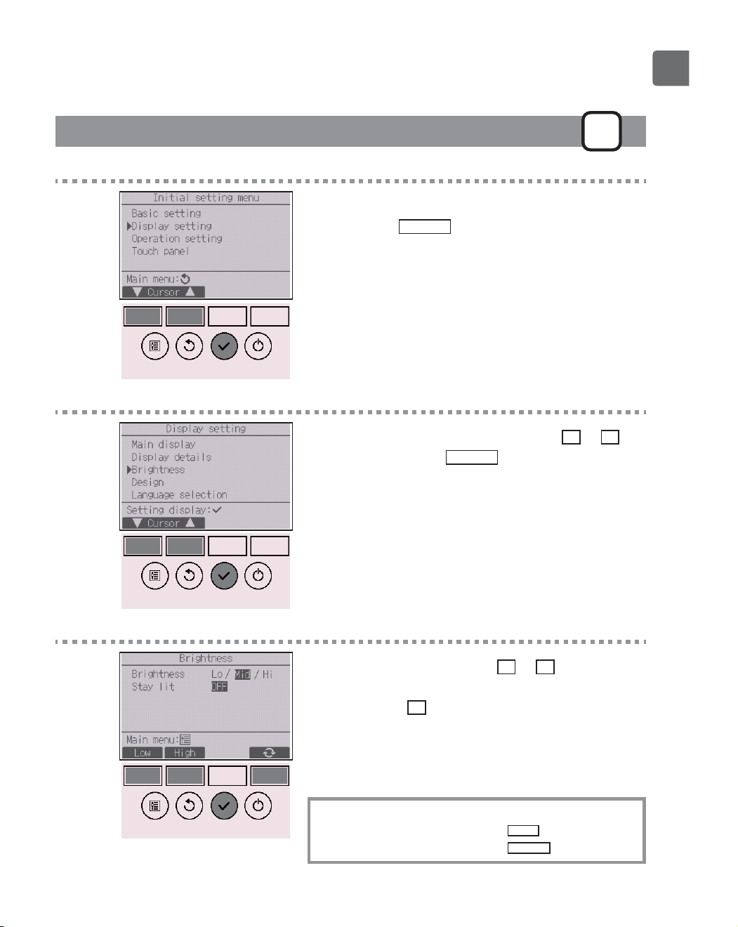
Brightness
P
Button operation
1
Select “Display setting” from the Initial setting menu,
and press the
SELECT
button.
2
Move the cursor to “Brightness” with the
F1
or
F2
button, and press the
SELECT
button.
3
Adjust the brightness with the
F1
or
F2
button.
“ON” or “OFF” can be selected for the “Stay lit”
setting with the
F4
button.
When “ON” is selected, the backlight will remain lit
dimly even after the specified time has elapsed.
Navigating through the screens
To go back to the Main menu ..........
MENU
button
To return to the previous screen
......
RETURN
button
62
Function settings
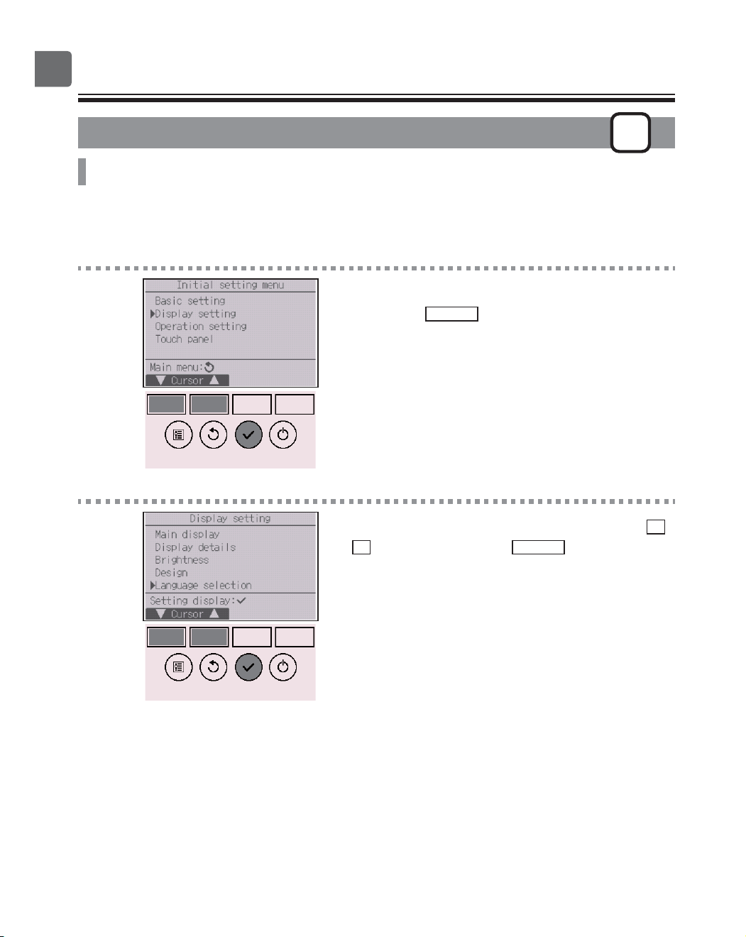
Language selection
P
Function description
The desired language can be set. The language options are English, French, German, Spanish,
Italian, Portuguese, Swedish, Russian, Greek, Turkish, Dutch, Czech, Hungarian, and Polish.
Button operation
1
Select “Display setting” from the Initial setting menu,
and press the
SELECT
button.
2
Move the cursor to “Language selection” with the
F1
or
F2
button, and press the
SELECT
button.
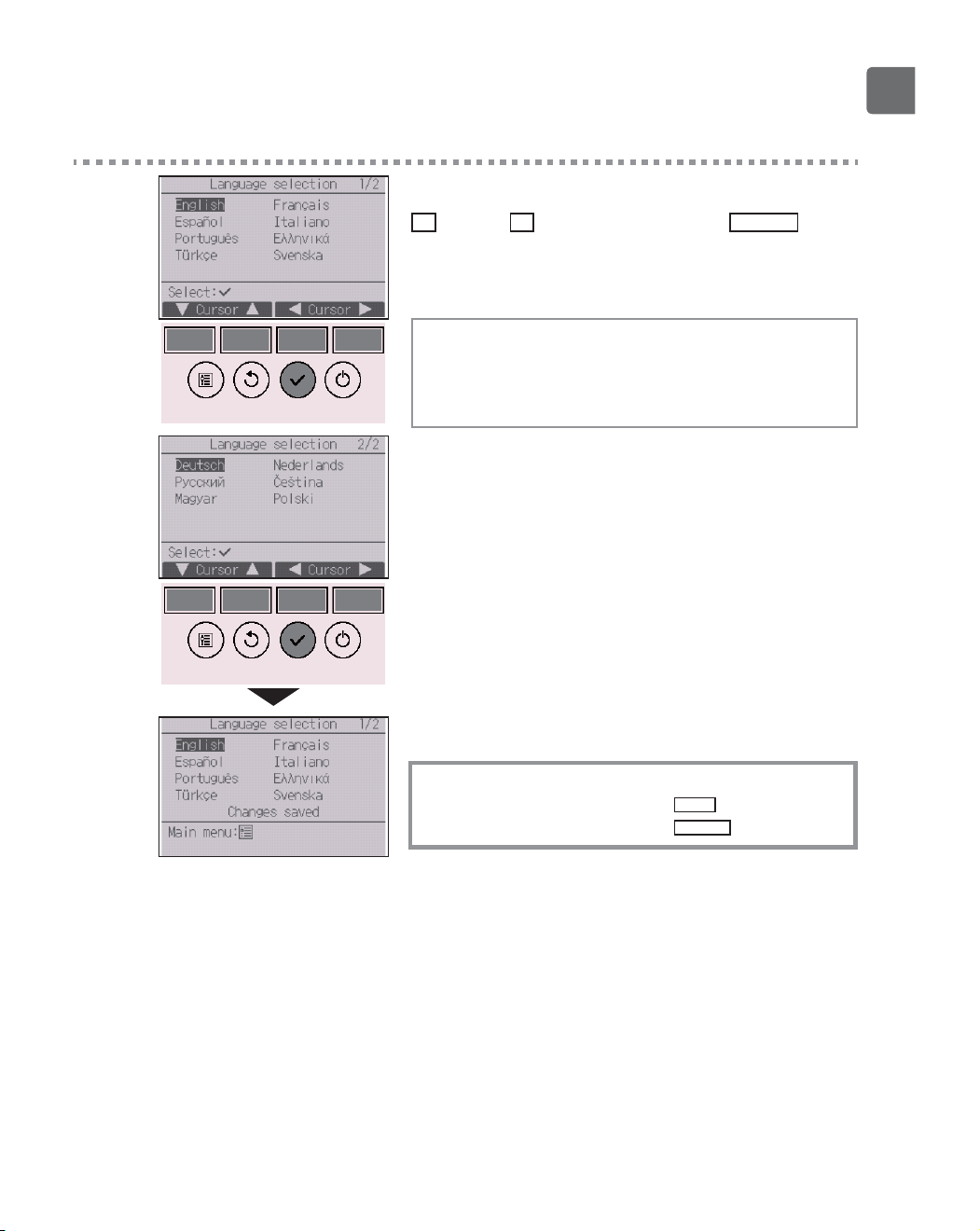
63
3
Move the cursor to the language you desire with the
F1
through
F4
buttons, and press the
SELECT
button
to save the setting.
When the power is on for the first time, the Language
selection screen will be displayed. Select a desired
language. The system will not start-up without
language selection.
A screen will appear that indicates the setting has
been saved.
Navigating through the screens
To go back to the Main menu ..........
MENU
button
To return to the previous screen
......
RETURN
button
64
Function settings
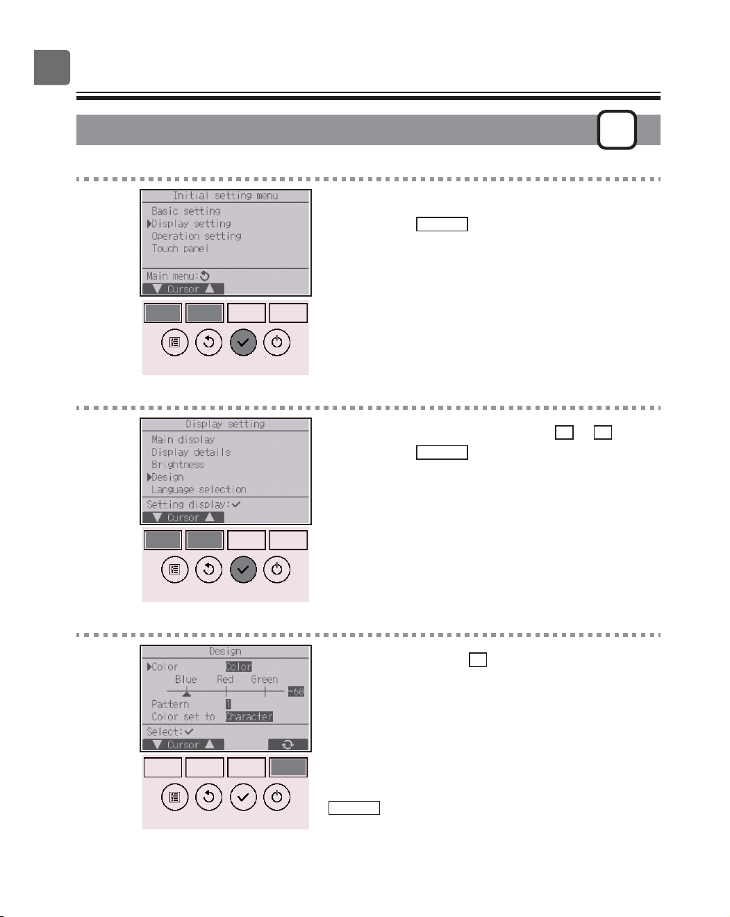
Design
P
Button operation
1
Select “Display setting” from the Initial setting menu,
and press the
SELECT
button.
2
Move the cursor to “Design” with the
F1
or
F2
button,
and press the
SELECT
button.
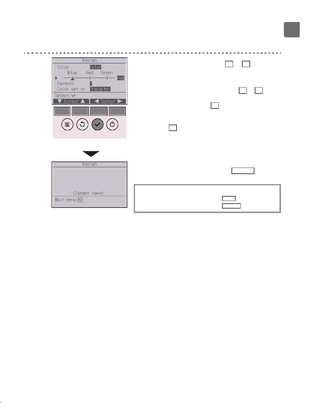
3
Select “Color” with the
F4
button.
•
Color: The display color can be selected. (Refer to the next
page.)
•
White: Monochrome display (white basis)
•
Black: Monochrome display (black basis)
When “White” or “Black” is selected, press the
SELECT
button. When “Color” is selected, select the
desired color referring to the next page.
65
4
Select the following item with the
F1
or
F2
button,
and set the desired display color for each item.
•
Color shade: Set the color shade with the
F3
or
F4
button. (The settable range is -90 to 89.)
•
Pattern: Set the color with the
F4
button.
•
Color set to: Select “Character” or “BG” (Background) as a
target to which the color is applied with the
F4
button.
The sample color below the function buttons will
change according to the setting.
Set the desired color, and press the
SELECT
button.
Navigating through the screens
To go back to the Main menu ...........
MENU
button
To return to the previous screen
.......
RETURN
button
66
Function settings
Touch panel calibration
P
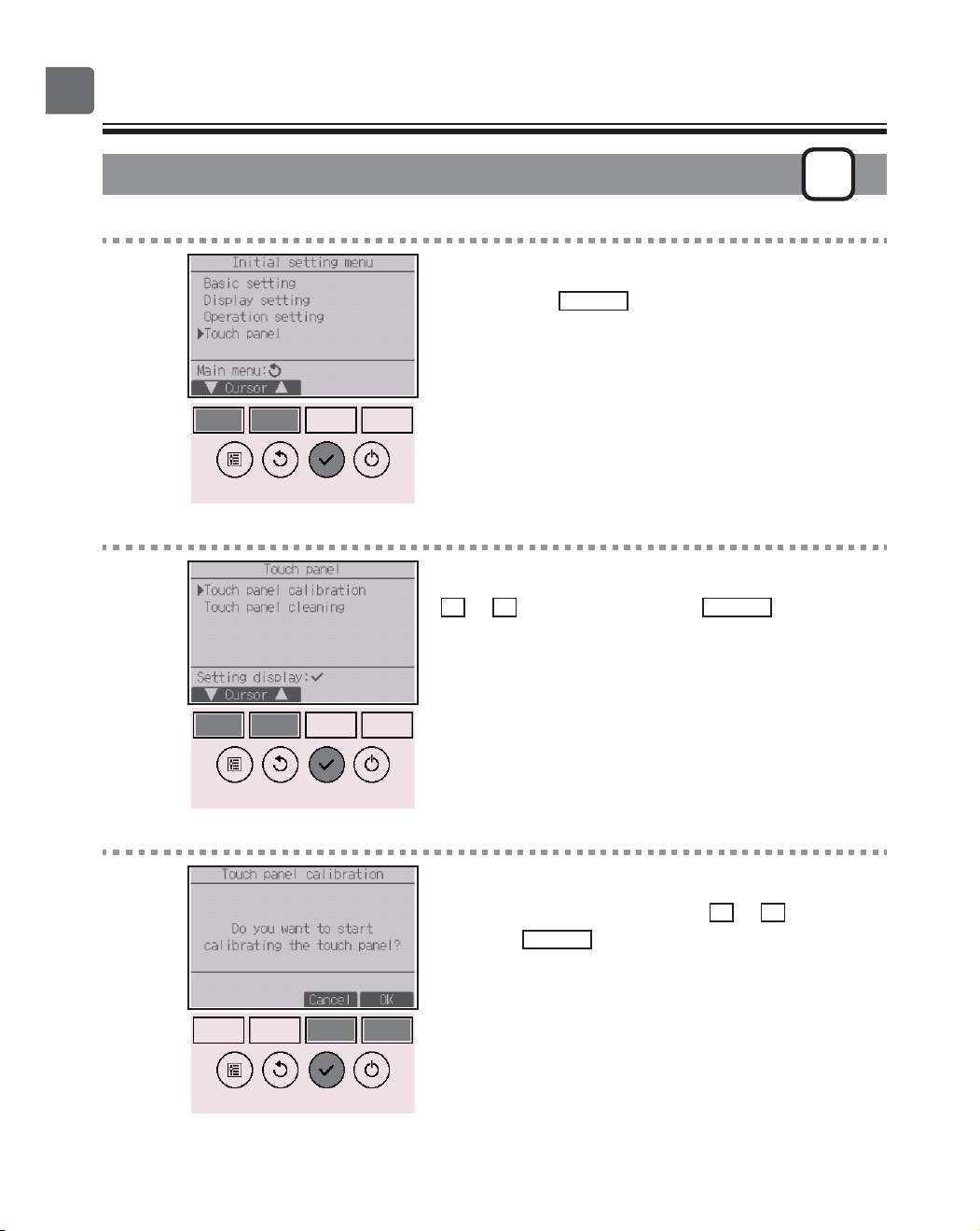
Button operation
1
Select “Touch panel” from the Initial setting menu,
and press the
SELECT
button.
2
Move the cursor to “Touch panel calibration” with the
F1
or
F2
button, and press the
SELECT
button.
3
A confirmation screen will appear.
Select “Cancel” or “OK” with the
F3
or
F4
button, and
press the
SELECT
button.
67
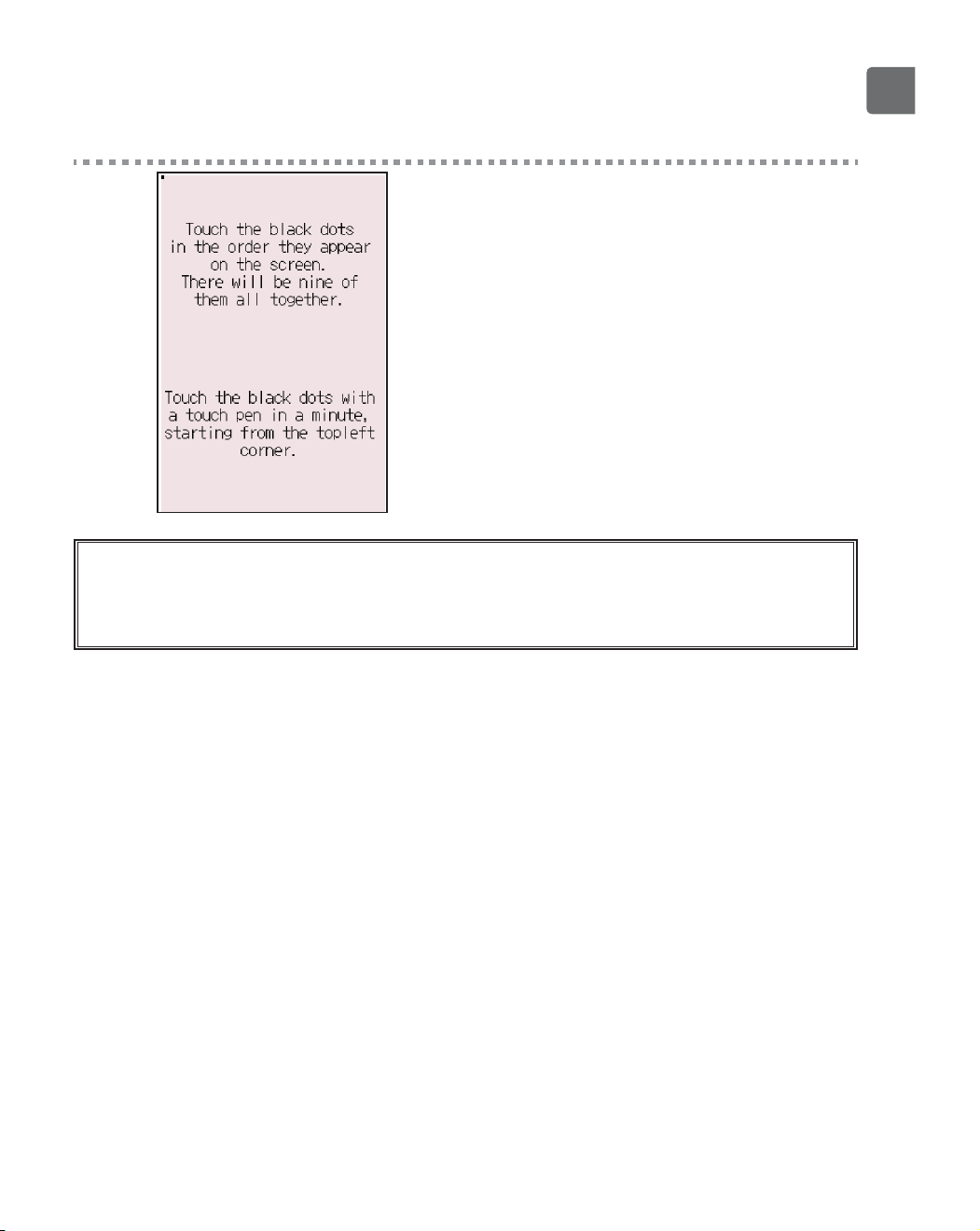
4
Touch the nine black dots in the order they appear on
the screen.
When all nine black dots are touched, the calibration
is complete, and the display will return to the touch
panel menu.
If the touch panel is left untouched for one minute, the calibration will be canceled and the display will
automatically return to the previous screen.
To properly calibrate the touch panel, use a pointy but not sharp object to touch the dots.
*
A sharp object may damage or scratch the touch panel.

68
Function settings
Touch panel cleaning
P
Button operation
1
Select “Touch panel” from the Initial setting menu,
and press the
SELECT
button.
2
Move the cursor to “Touch panel cleaning” with the
F1
or
F2
button, and press the
SELECT
button.
3
A confirmation screen will appear.
Select “Cancel” or “OK” with the
F3
or
F4
button, and
press the
SELECT
button.
69
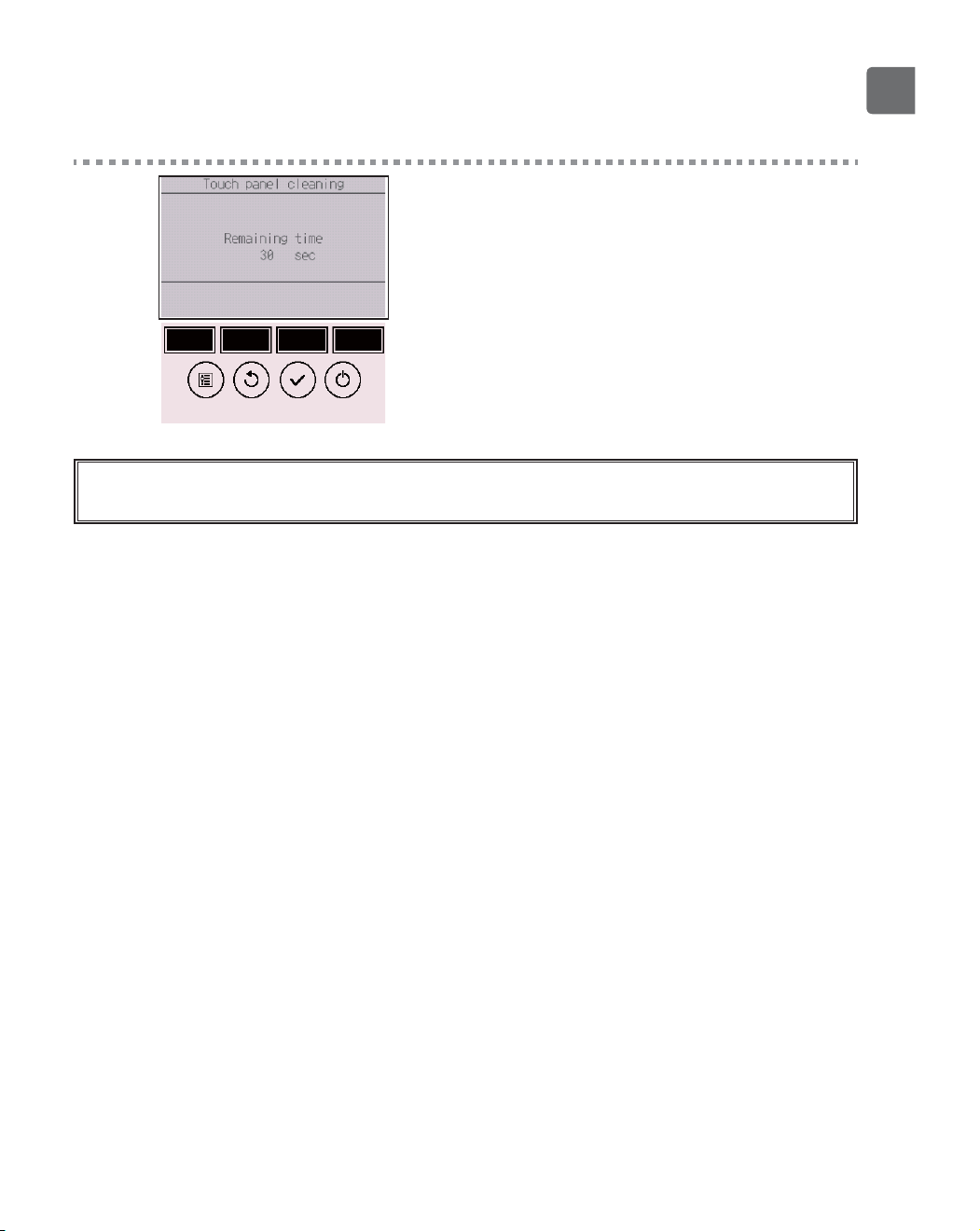
4
This screen allows the user to wipe the touch panel
for 30 seconds without accidentally changing the
settings.
The display will return to the touch panel menu after
the 30 seconds.
Wipe with a soft dry cloth, a cloth soaked in water with mild detergent, or a cloth dampened with ethanol. Do
not use acidic, alkaline, or organic solvents.
70
Function settings
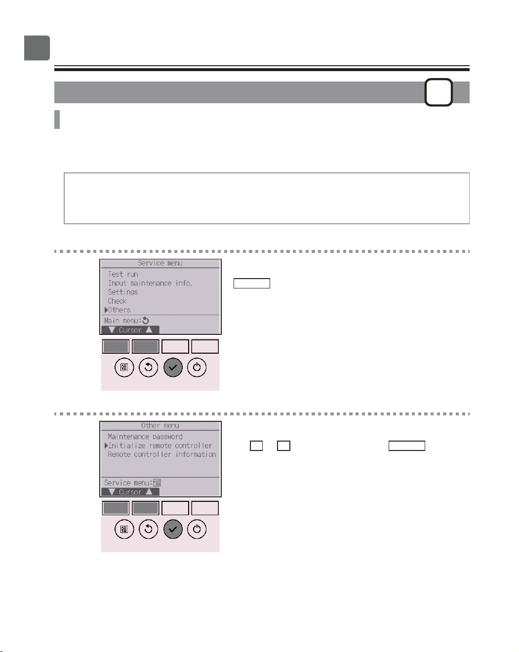
Initialize remote controller
P
Function description
The remote controller can be initialized to the factory shipment state. Note that the following data will
be initialized.
The remote controller will automatically be started up after being initialized.
Timer setting, Weekly timer setting, OU silent mode setting, Energy saving setting, Energy saving
option setting, Clock setting, Daylight saving time setting, Main display setting, Brightness setting,
Display details setting, Design setting, Auto mode setting, Model name setting, Serial No. setting,
Dealer information setting, Error information, Administrator password, Maintenance password
Button operation
1
Select “Others” from the Service menu, and press the
SELECT
button.
2
Move the cursor to “Initialize remote controller” with
the
F1
or
F2
button, and press the
SELECT
button.
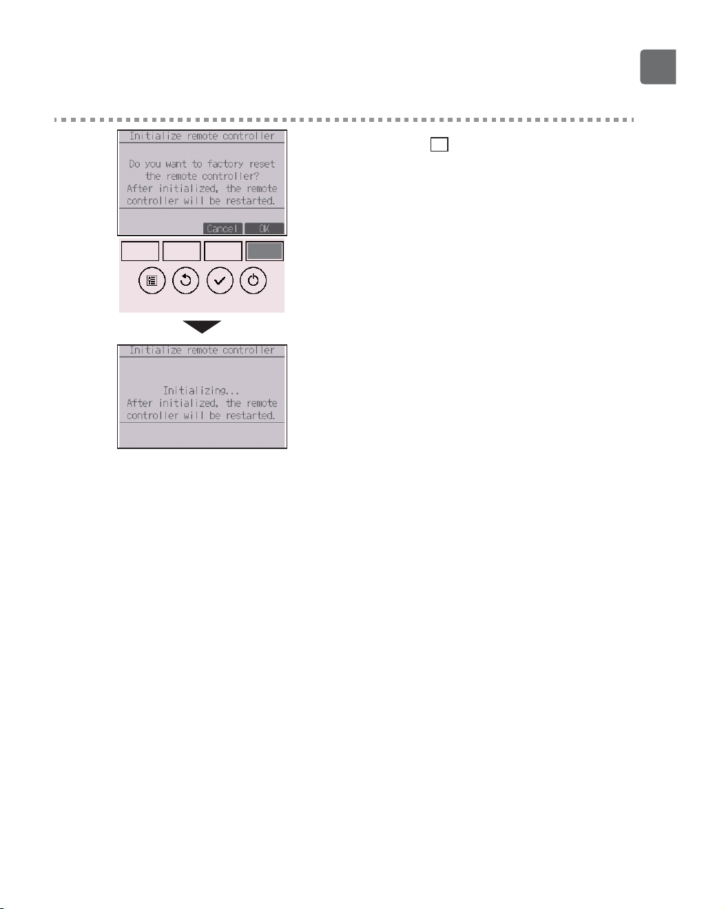
71
3
Select “OK” with the
F4
button.
The remote controller will automatically be started up
after being initialized.
72
Function settings
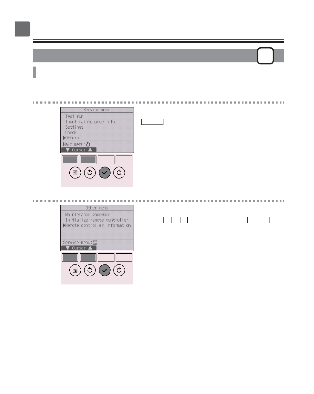
Remote controller information
P
Function description
The information of the remote controller in use can be checked.
Button operation
1
Select “Others” from the Service menu, and press the
SELECT
button.
2
Move the cursor to “Remote controller information”
with the
F1
or
F2
button, and press the
SELECT
button.
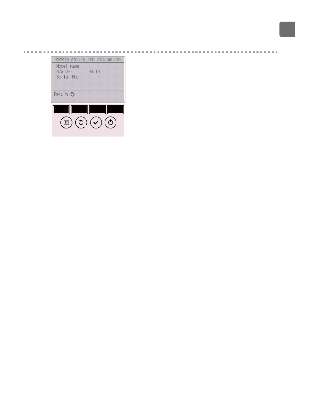
73
3
The model name, software version, and serial
number of the remote controller in use can be
checked.
74
Troubleshooting
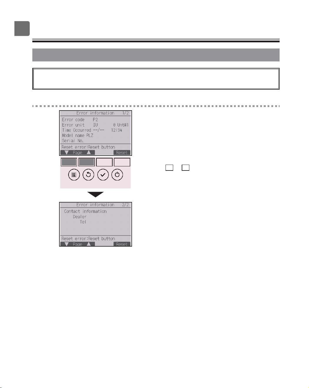
Error information
When an error occurs, the following screen will appear and the operation LED will
blink. Check the error status, stop the operation, and consult your dealer.
Button operation
1
Error code, error unit, refrigerant address, unit model
name, date and time on which an error occurred, and
serial number will appear.
The model name and serial number will appear only if
the information have been registered.
Press the
F1
or
F2
button to go to the next page.
Contact information (dealer’s phone number) will
appear if the information have been registered.
75
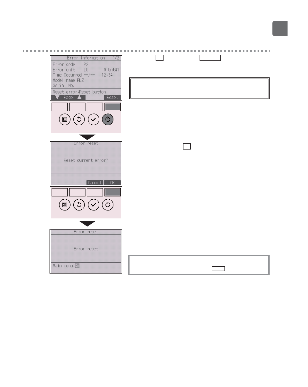
2
Press the
F4
button or the
ON/OFF
button to reset
the error that is occurring.
Errors cannot be reset while the ON/OFF
operation is prohibited.
Select “OK” with the
F4
button.
A confirmation screen will appear.
Navigating through the screens
To go back to the Main menu ..........
MENU
button
76
Troubleshooting
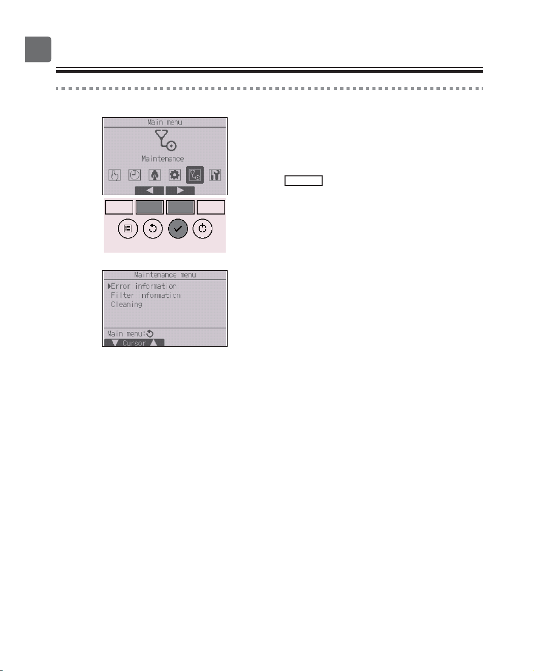
Checking the error information
While no errors are occurring, page 2/2 of the error
information (refer to page 74) can be viewed from
the menu operation.
Select “Maintenance” menu from the Main menu, and
press the
SELECT
button.
To display the error information screen, select “Error
information” from the Maintenance menu.
Errors cannot be reset.
77
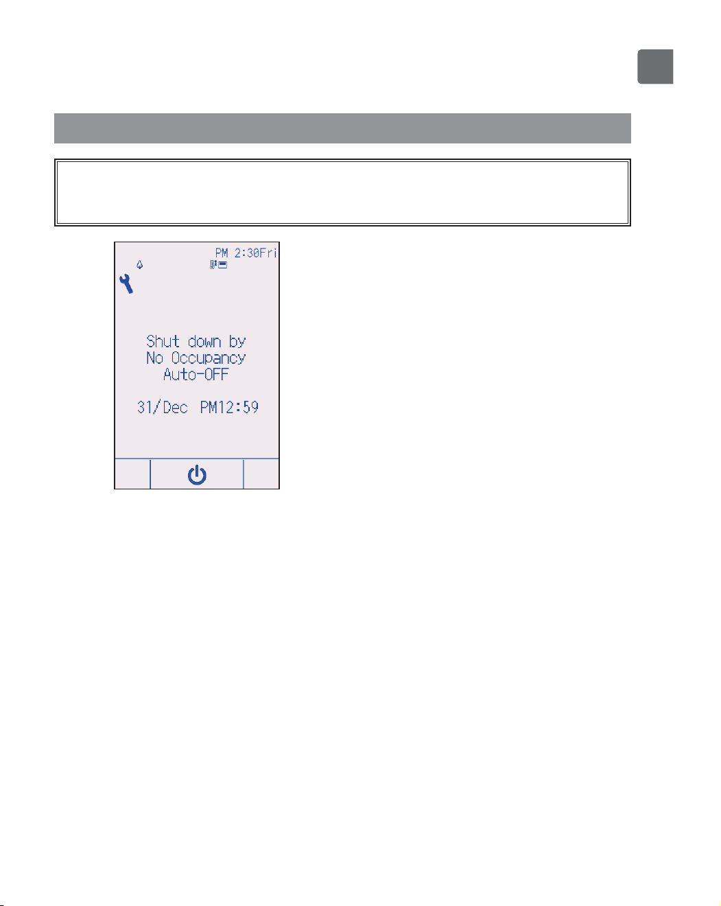
No occupancy Auto-OFF
The following screen will appear for the 3D i-See sensor panel model when the unit
is stopped due to the No occupancy Auto-OFF function of the energy saving option.
Refer to the indoor unit Instruction Book for the 3D i-See sensor setting.
78
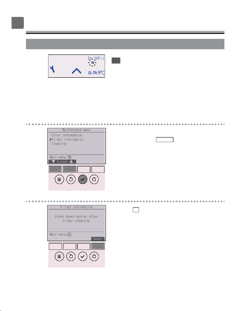
Maintenance
Filter information
will appear on the Status display and the Main
display in the Full mode when it is time to clean the
filters.
Wash, clean, or replace the filters when this sign
appears.
Refer to the indoor unit Instructions Manual for
details.
Button operation
1
Select “Filter information” from the Maintenance
menu, and press the
SELECT
button.
2
Press the
F4
button to reset filter sign.
Refer to the indoor unit Instructions Manual for how
to clean the filter.
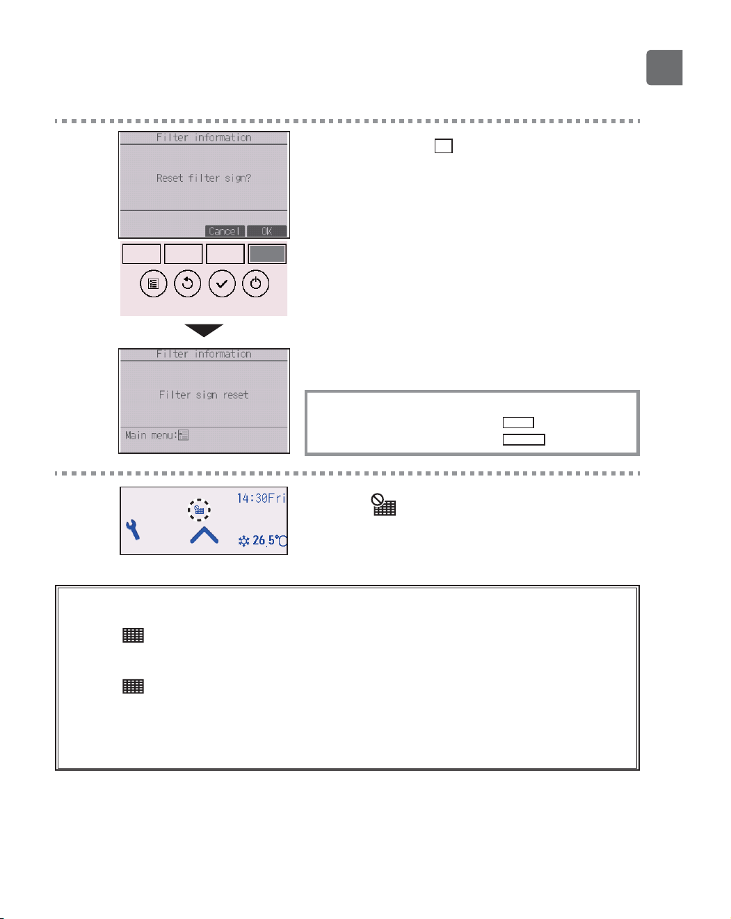
79
3
Select “OK” with the
F4
button.
A confirmation screen will appear.
Navigating through the screens
To go back to the Main menu ..........
MENU
button
To return to the previous screen
......
RETURN
button
When the is displayed on the Status display and
the Main display in the Full mode, the system is
centrally controlled and the filter sign cannot be reset.
If two or more indoor units are connected, filter cleaning timing for each unit may be different,
depending on the filter type.
The icon will appear when the filter on the main unit is due for cleaning.
When the filter sign is reset, the cumulative operation time of all units will be reset.
The icon is scheduled to appear after a certain duration of operation, based on the premise that
the indoor units are installed in a space with ordinary air quality. Depending on the air quality, the
filter may require more frequent cleaning.
The cumulative time at which filter needs cleaning depends on the model.
80
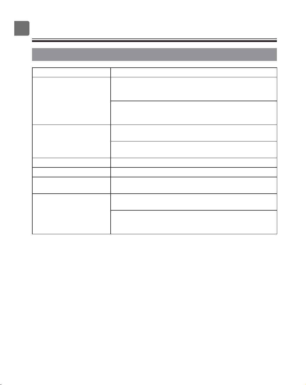
Specifications
Controller specifications
Specification
Product size Standard (PAR-CT01MAA(R)-SB/PAR-CT01MAA-S):
65(W) × 120(H) × 14.1(D) mm (2 9/16 × 4 23/32 × 9/16 [in])
(not including the protruding part)
Premium (PAR-CT01MAA(R)-PB):
68(W) × 120(H) × 14.1(D) mm (2 11/16 × 4 23/32 × 9/16 [in])
(not including the protruding part)
Net weight Standard (PAR-CT01MAA(R)-SB/PAR-CT01MAA-S):
0.09 kg (13/64 lbs)
Premium (PAR-CT01MAA(R)-PB):
0.10 kg (7/32 lbs)
Rated power supply voltage 12 VDC (supplied from indoor units)
Power consumption 0.6 W
Usage environment Temperature 0 ~ 40ºC (32 ~ 104ºF)
Humidity 25 ~ 90%RH (with no dew condensation)
Material Standard (PAR-CT01MAA(R)-SB/PAR-CT01MAA-S)
Main body: ABS
Premium (PAR-CT01MAA(R)-PB)
Main body: ABS
Side plate: Aluminum
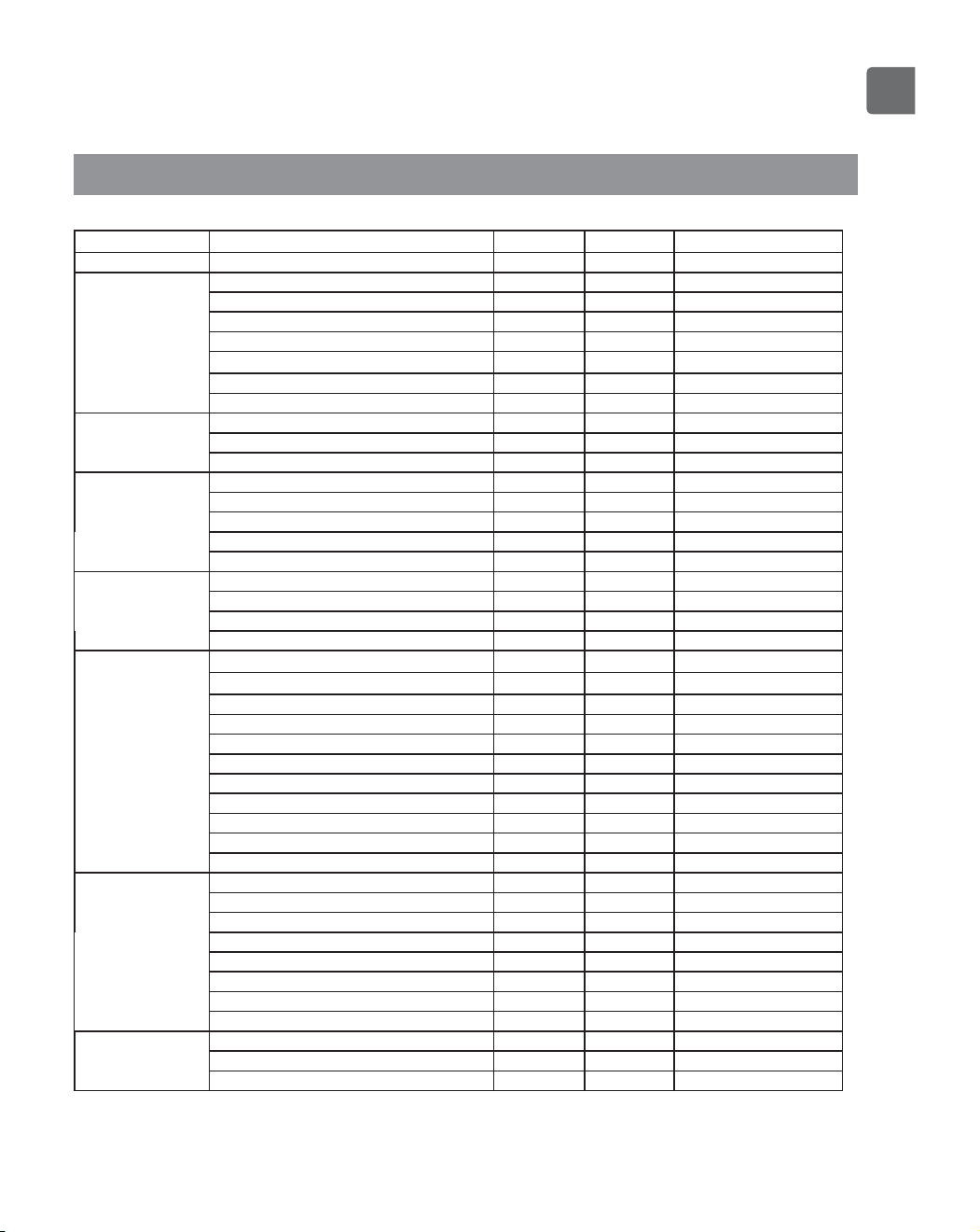
81
Function list (as of October 1, 2017)
○ : Supported × : Unsupported
Function
CITY MULTI
Mr. SLIM Required password
Power Power ON/OFF
○○
-
Settings Operation mode
○○
-
Auto (dual set point) mode
○○
-
Preset temperature
○○
-
Fan speed
○○
-
Vane
○○
-
Louver
○○
-
Ventilation
○○
-
Operation menu High power
×○
-
Manual vane angle
○○
-
3D i-See sensor
○○
-
Timer menu Timer (On/Off timer)
○○
administrator
Timer (Auto-Off timer)
○○
administrator
Weekly timer
○○
administrator
OU silent mode
○○
administrator
Night setback
○○
administrator
Energy saving
menu
Temperature range restriction
○○
administrator
Operation lock function
○○
administrator
Auto return
○○
administrator
Schedule
×○
administrator
Initial setting menu Clock
○○
administrator
Clock display format setting
○○
administrator
Daylight saving time
○○
administrator
Main display
○○
administrator
Icon explanation
○○
administrator
Brightness
○○
administrator
Language selection
○○
administrator
Design
○○
administrator
Touch panel calibration
○○
administrator
Touch panel cleaning
○○
administrator
Password (Administrator)
○○
administrator
Service menu Initialize remote controller
○○
maintenance
Remote controller information
○○
maintenance
Test run
○○
maintenance
Model information input
○○
maintenance
Dealer information input
○○
maintenance
Function setting
○○
maintenance
Smooth maintenance
×○
maintenance
Password (Maintenance)
○○
maintenance
Maintenance menu Auto descending panel
○○
-
Error information
○○
-
Filter information
○○
-
*
The supported functions vary depending on the unit model.
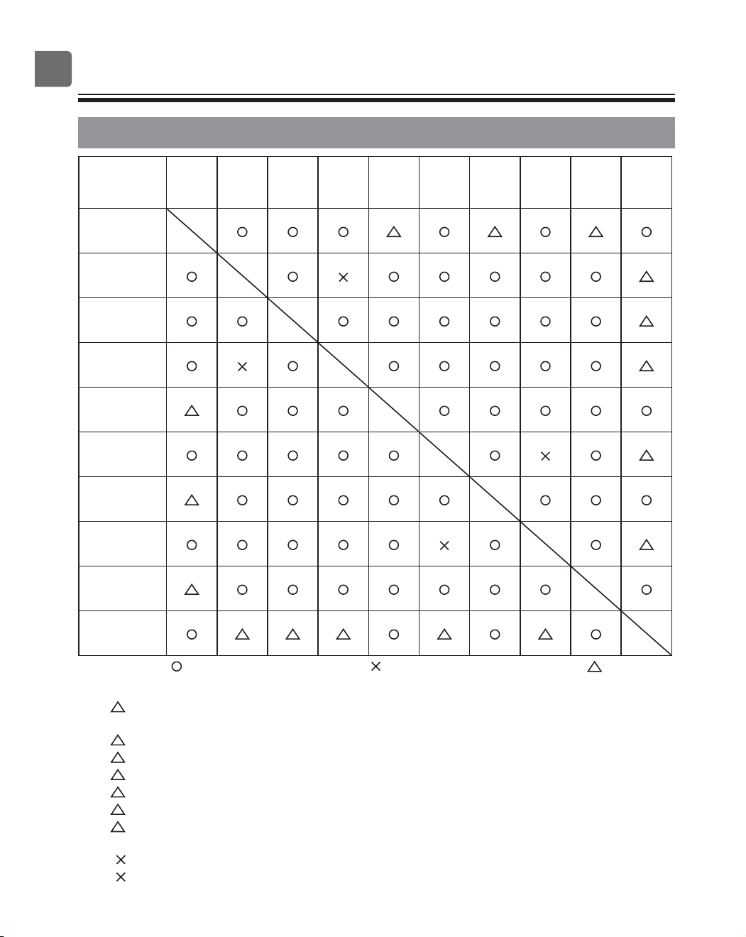
82
Specifications
List of functions that can/cannot be used in combination
High
power
On/Off
timer
Auto-off
timer
Weekly
timer
OU
silent
mode
Temperature
range
Operation
lock
Auto
return
Energy
saving
schedule
Night
setback
High power
On/Off timer
Auto-off timer
Weekly timer
OU silent
mode
Temperature
range
Operation lock
Auto return
Energy saving
schedule
Night setback
: Can be used in combination : Cannot be used in combination : Restricted
1: This function is enabled after completing the high power operation because the high power
operation has the higher priority.
2: This function cannot be operated if some operation is locked.
3: Night setback function cannot be used when the unit is in operation by On/Off timer setting.
4: Auto-off function cannot be used for Night setback operation.
5: Night setback function cannot be used when the unit is in operation by Weekly timer setting.
6: Temperature range setting cannot be used for Night setback operation.
7: Auto return function cannot be used for Night setback operation.
1: Weekly timer setting is not effective because On/Off timer has the higher priority.
2: Auto return function cannot be used because Temperature range setting has the higher priority.
121
13
4
15
1
26
2
27
1
345 6 7