~
VACUUM
OIL
&
FLUID
EXTRACTOR
& DISCHARGE 6L
TR
& 18L TR
MODEL NO'S: TP6905.V2, TP6906.V2
Thank you for purchasing a Sealey product. Manufactured to a high standard, this product will, if used according to these instructions,
and properly maintained, give you years of trouble free performance.
IMPORTANT:
PLEASE READ THESE INSTRUCTIONS CAREFULLY. NOTE THE SAFE OPERATIONAL REQUIREMENTS, WARNINGS & CAUTIONS. USE
THE PRODUCT CORRECTLY AND WITH CARE FOR THE PURPOSE FOR WHICH
IT
IS
INTENDED. FAILURE
TO
DO
SO
MAY
CAUSE DAMAGE AND/OR
PERSONAL INJURY AND WILL INVALIDATE THE WARRANTY. KEEP THESE INSTRUCTIONS SAFE FOR FUTURE USE.
Refer to
instruction
manual
Wear protective
gloves
1.
SAFETY
Wear face Wear protective
shield clothing
□
WARNING! Ensure Health & Safety, local authority, and general workshop practice regulations are strictly adhered to when using this
equipment.
IMPORTANT! Ensure that you wear protective clothing, gloves, goggles, face mask as appropriate for the fluid being extracted.
✓
Keep the extractor clean and maintain it
in
good condition (use
an
authorised service agent).
✓
Replace
or
repair damaged parts. Use genuine parts only. Unauthorised parts may be dangerous and will invalidate the warranty.
✓
Check extractor connections and fittings before use. When the unit
is
in
use check that there are no leaks.
✓
Ensure that the extractor's tank capacity exceeds the amount of fluid to be collected.
✓
Ensure that the end of the suction tube
is
fully submerged
in
the fluid before operating.
✓
When not
in
use store
in
a safe,
dry,
childproof area.
✓
Keep the work area clean, uncluttered and ensure there
is
adequate lighting.
✓
Maintain correct balance
and
footing. Ensure the floor
is
not slippery
and
wear non-slip shoes.
✓
Keep children
and
unauthorised persons away from the working area.
✓
Dispose
of
waste fluids
in
accordance with local authority regulations.
□
WARNING!
DO
NOT allow uncontrolled discharge of fluids thus polluting the environment.
✓
Use only to extract engine
or
transmission oils,
or
similar NON-corrosive fluids. Unit may also be used for the transfer of water.
x
DO
NOT use to extract hazardous or harmful chemicals, solvents, petrol, diesel, kerosene, alkaline
or
acids.
If
by chance such fluids
are used
in
the unit, it must be immediately drained and thoroughly cleaned. Use with prohibited fluids will invalidate your warranty.
x
DO
NOT store fluids
in
the extractor's tank. After extracting fluid, it must be emptied into
an
approved receptacle as soon as possible.
x
DO
NOT dismantle, tamper or adapt the extractor for any purpose other than for which it
is
designed.
x
DO
NOT store
in
areas of high temperature, direct sunlight, rain
or
snow.
x
DO
NOT connect these units to
an
air compressor.
x
DO
NOT dismantle these units.
x
DO
NOT leave these units
in
a pressurised state.
□ WARNING! When the extractor's tank contains liquid that
is
under pressure
DO
NOT remove or insert the extension tube connector into
the inlet/outlet fitting as this may result
in
a sudden discharge of liquid that could be dangerous.
✓
Always press the pressure relief button before connecting or disconnecting the extension tube.
2.
INTRODUCTION
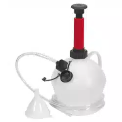
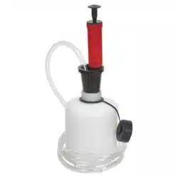
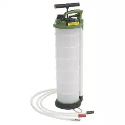
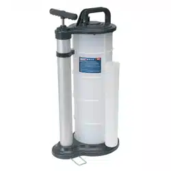
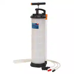
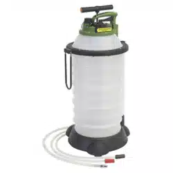
6Itr (TP6905) or 18Itr (TP6906) capacity device constructed from composite materials and suitable for extraction of all types of engine,
transmission and lubricating oils from cars, motorcycles, marine engines, stationary engines and industrial machinery. Features a
controlled discharge function for emptying the unit. Suitable also for low viscosity fluids such as water. Supplied with
05.8,
06.7mm
suction probes and a
1.1
m extension tube. Uses probes to drain engine oil through the dipstick hole. Also suitable for draining fish tanks,
basins and sinks.
3.
SPECIFICATION
Model
No:
TP6905.V2 TP6906.V2
TP6905
Capacity 6L 18L
Suction probes
05.8
x 870mm,
06.7
x 870mm
05.8
x 870mm,
06.7
x 870mm
Extension tube
09.8
x 1010mm
09.8
x 1010mm,
Wheels No Yes
© Jack Sealey Limited Original Language Version
TP6905.V2, TP6906.V2 lssue:5 (3) 04/05/23 ]
4.
MAIN
FEATURES
4.1.
4.2.
4.3.
4.4.
4.5.
4.6.
4.7.
4.8.
4.9.
4.10.
4.11.
4.12.
4.13.
4.14.
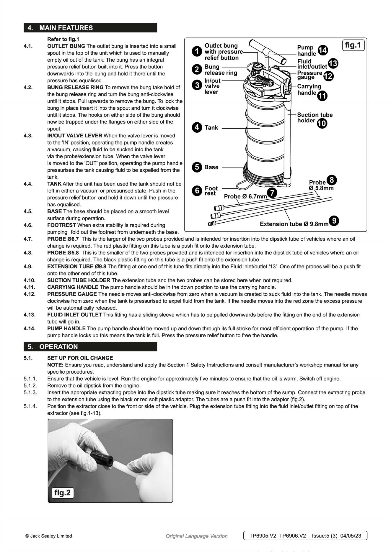
Refer to fig.1
OUTLET BUNG The outlet bung
is
inserted into a small
spout
in
the top
of
the unit which
is
used to manually
empty oil out
of
the tank. The bung has
an
integral
pressure relief button built into
it.
Press the button
downwards into the bung and hold it there until the
pressure has equalised.
BUNG RELEASE RING
To
remove the bung take hold of
the bung release ring and turn the bung anti-clockwise
until it stops. Pull upwards to remove the bung.
To
lock the
bung
in
place insert it into the spout and turn it clockwise
until it stops. The hooks
on
either side
of
the bung should
now be trapped under the flanges
on
either side
of
the
spout.
IN/OUT VALVE LEVER When the valve lever
is
moved
to the 'IN' position, operating the pump handle creates
a vacuum, causing fluid to be sucked into the tank
via the probe/extension tube. When the valve lever
is
moved to the 'OUT' position, operating the pump handle
pressurises the tank causing fluid to be expelled from the
tank.
TANK After the unit has been used the tank should not be
left
in
either a vacuum
or
pressurised state. Push
in
the
pressure relief button and hold it down until the pressure
has equalised.
BASE The base should be placed
on
a smooth level
surface during operation.
FOOTREST When extra stability
is
required during
pumping fold out the footrest from underneath the base.
0
Outlet
bung
with
pressure--~
relief button
A
Bung
V release
ring
e
In/out
valve
lever
Orank
E)sase
A Foot
V rest
Pump
~
[ fig.1 ]
-----handle
W
Fluid
~
i.-,,:i:::,r---inlet/outlet
'£'
Pressure~
gauge
~
Carrying
handle4D
Suction tube
holder«i}
Extension tube 0
9.8mm0
PROBE
06.7
This is the larger of the two probes provided and
is
intended for insertion into the dipstick tube of vehicles where
an
oil
change
is
required. The
red
plastic fitting
on
this tube
is
a push fit onto the extension tube.
PROBE
05.8
This is the smaller of the two probes provided and
is
intended for insertion into the dipstick tube of vehicles where
an
oil
change
is
required. The black plastic fitting
on
this tube
is
a push fit onto the extension tube.
EXTENSION TUBE
09.8
The fitting at one end
of
this tube fits directly into the Fluid inlet/outlet '13'. One
of
the probes will be a push fit
onto the other end of this tube.
SUCTION TUBE HOLDER The extension tube and the two probes can be stored here when not required.
CARRYING HANDLE The pump handle should be
in
the down position to use the carrying handle.
PRESSURE GAUGE The needle moves anti-clockwise from zero when a vacuum
is
created to suck fluid into the tank. The needle moves
clockwise from zero when the tank
is
pressurised to expel fluid from the tank. If the needle moves into the
red
zone the excess pressure
will be automatically released.
FLUID INLET OUTLET This fitting has a sliding sleeve which has to be pulled downwards before the fitting
on
the end
of
the extension
tube will go in.
PUMP HANDLE The pump handle should be moved up and down through its full stroke for most efficient operation of the pump. If the
pump handle locks up this means the tank
is
full. Press the pressure relief button to free the handle.
5.
OPERATION
5.1.
5.1.1.
5.1.2.
5.1.3.
5.1.4.
SET
UP
FOR OIL CHANGE
NOTE: Ensure you read, understand and apply the Section 1 Safety Instructions and consult manufacturer's workshop manual for any
specific procedures.
Ensure that the vehicle
is
level. Run the engine for approximately five minutes to ensure that the oil
is
warm. Switch off engine.
Remove the oil dipstick from the engine.
Insert the appropriate extracting probe into the dipstick tube making sure it reaches the bottom of the sump. Connect the extracting probe
to the extension tube using the black or red soft plastic adaptor. The tubes are a push fit into the adaptor (fig.2).
Position the extractor close to the front
or
side of the vehicle. Plug the extension tube fitting into the fluid inlet/outlet fitting
on
top
of
the
extractor (see fig.1-13).
© Jack Sealey Limited
Original Language Version
[ TP6905.V2, TP6906.V2 lssue:5 (3) 04/05/23 ]
5.2.
5.2.1.
5.2.2.
5.2.3.
5.2.4.
5.2.5.
5.2.6.
5.2.7.
5.3.
5.3.1.
5.3.2.
5.3.3.
5.3.4.
5.3.5.
5.3.6.
5.3.7.
5.3.8.
□
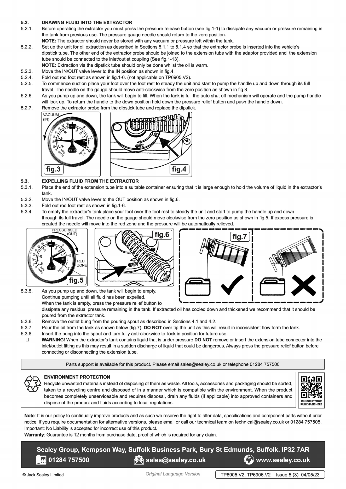
DRAWING FLUID INTO THE EXTRACTOR
Before operating the extractor you must press the pressure release button (see fig.1-1) to dissipate any vacuum or pressure remaining
in
the tank from previous use. The pressure gauge needle should return to the zero position.
NOTE: The extractor should never be stored with any vacuum
or
pressure left within the tank.
Set up the unit for oil extraction as described
in
Sections 5.1.1 to 5.1.4 so that the extractor probe
is
inserted into the vehicle's
dipstick tube. The other end of the extractor probe should be joined to the extension tube with the adaptor provided and the extension
tube should be connected to the inlet/outlet coupling (See fig.1-13).
NOTE: Extraction via the dipstick tube should only be done whilst the oil
is
warm.
Move the IN/OUT valve lever to the
IN
position as shown
in
fig.4.
Fold out
rod
foot rest as shown
in
fig.1-6. (not applicable
on
TP6905.V2).
To
commence suction place your foot over the foot rest to steady the unit and start to pump the handle up and down through its full
travel. The needle
on
the gauge should move anti-clockwise from the zero position as shown
in
fig.3.
As you pump up and down, the tank will begin to fill. When the tank
is
full the auto shut off mechanism will operate and the pump handle
will lock
up.
To
return the handle to the down position hold down the pressure relief button and push the handle down.
Remove the extractor probe from the dipstick tube and replace the dipstick.
EXPELLING FLUID FROM THE EXTRACTOR
Place the end of the extension tube into a suitable container ensuring that it
is
large enough to hold the volume
of
liquid
in
the extractor's
tank.
Move the IN/OUT valve lever to the OUT position as shown
in
fig.6.
Fold out
rod
foot rest as shown
in
fig.1-6.
To
empty the extractor's tank place your foot over the foot rest to steady the unit and start to pump the handle up and down
through its full travel. The needle
on
the gauge should move clockwise from the zero position as shown
in
fig.5. If excess pressure
is
created the needle will move into the
red
zone and the pressure will be automatically relieved.
PRE
SS
URI
S
ED
,-----------,,----------,
(OUT)
'-...--='---'
I [ fig. 7
l;
I
As you pump up and down, the tank will begin to empty.
Continue pumping until all fluid has been expelled.
When the tank
is
empty, press the pressure relief button to
I
(1//j~~=I
I
I I ~ - ;..a> I
I ~
--
~ - I I
I I I
I I I
!r::J
✓
!~X!
I I I
\---------------------~
dissipate any residual pressure remaining
in
the tank. If extracted oil has cooled down and thickened we recommend that
it
should be
poured from the extractor tank.
Remove the outlet bung from the pouring spout as described
in
Sections
4.1
and 4.2.
Pour the oil from the tank as shown below (fig.?). DO NOT over tip the unit as this will result
in
inconsistent flow form the tank.
Insert the bung into the spout and turn fully anti-clockwise to lock
in
position for future use.
WARNING! When the extractor's tank contains liquid that
is
under pressure DO NOT remove or insert the extension tube connector into the
inlet/outlet fitting as this may result
in
a sudden discharge of liquid that could
be
dangerous. Always press the pressure relief button before
connecting or disconnecting the extension tube.
Parts support
is
available for this product. Please email [email protected] or telephone 01284 757500
ENVIRONMENT PROTECTION
Recycle unwanted materials instead of disposing of them as waste. All tools, accessories and packaging should be sorted,
taken to a recycling centre and disposed
of
in a manner which is compatible with the environment. When the product
becomes completely unserviceable and requires disposal, drain any fluids (if applicable) into approved containers and
dispose
of
the product and fluids according to local regulations.
REGISTER
YOUR
PURCHASE
HERE
Note:
It
is
our policy to continually improve products and as such we reserve the right to alter data, specifications and component parts without prior
notice.
If
you require documentation for alternative versions, please email
or
call our technical team on [email protected]
or
01284 757505.
Important: No Liability
is
accepted for incorrect use of this product.
Warranty: Guarantee
is
12
months from purchase date, proof of which
is
required for any claim.
Sealey Group, Kempson
Way,
Suffolk Business Park, Bury St Edmunds, Suffolk. IP32 7 AR
m 01284 757500
~
@www.sealey.co.uk
© Jack Sealey Limited
Original Language Version
[ TP6905.V2, TP6906.V2 lssue:5 (3) 04/05/23 ]