Loading ...
Loading ...
Loading ...
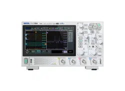
Compensation Signal
Output Terminal
Ground Terminal
Figure 4.6 Using the Compensation Signal
4. Set the probe ratio based on the attenuation of the probe, and then click or tap
> Auto.
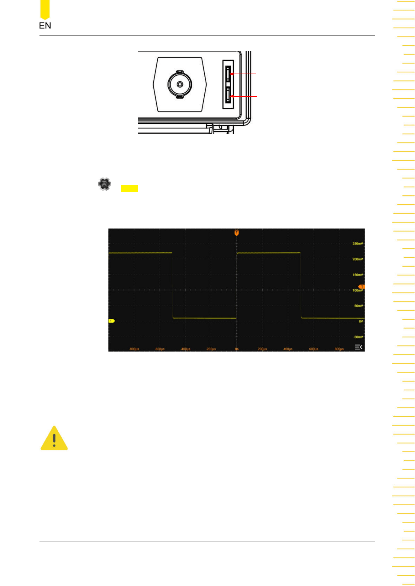
5. Observe the waveform on the display. In normal condition, you should see a
square waveform similar to the waveform shown in the figure below.
Figure 4.7 Square Waveform Signal
6. Test the other channels in the same way. If you see the waveform, but the square
wave is not shaped correctly as shown above, perform the procedure described in
Probe Compensation
. If you do not see the waveform, perform those steps again.
WARNING
To avoid electric shock when using the probe, please make sure that the insulated wire of
the probe is in good condition. Do not touch the metallic part of the probe when the
probe is connected to high voltage source.
4.3.7 Probe Compensation
When used for the first time, the oscilloscope probe must be compensated to match
the input characteristics of the oscilloscope channel to which it is connected. The
Quick Start
Copyright ©RIGOL TECHNOLOGIES CO., LTD. All rights reserved. DHO800 User Guide
15
Loading ...
Loading ...
Loading ...