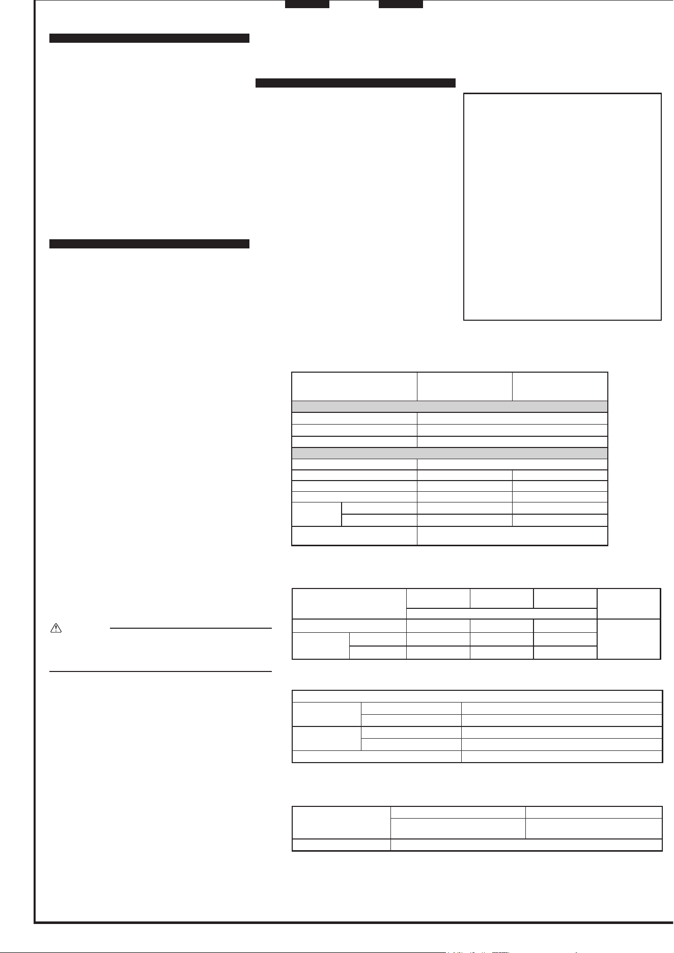
INDOOR UNIT
SERVICE MANUAL
INDOOR UNIT
Models
MSZ-FS06NA
-
U1
MSZ-FS09NA
-
U1
MSZ-FS12NA
-
U1
MSZ-FS15NA
-
U1
MSZ-FS18NA
-
U1
No. OBH872
PARTS CATALOG (OBB872)
Outdoor unit service manual
MUZ-FS∙NA(H) Series (OBH873)
MXZ-C∙NA,NAHZ Series (OBH702)
CONTENTS
1. TECHNICAL CHANGES ······························3
2. PART NAMES AND FUNCTIONS ··················4
3. SPECIFICATION ·········································5
4. OUTLINES AND DIMENSIONS ·····················6
5. WIRING DIAGRAM ·····································7
6. REFRIGERANT SYSTEM DIAGRAM ·············8
7. SERVICE FUNCTIONS ································9
8. MICROPROCESSOR CONTROL ················· 11
9. TROUBLESHOOTING ······························· 20
10. DISASSEMBLY INSTRUCTIONS ·················33
2
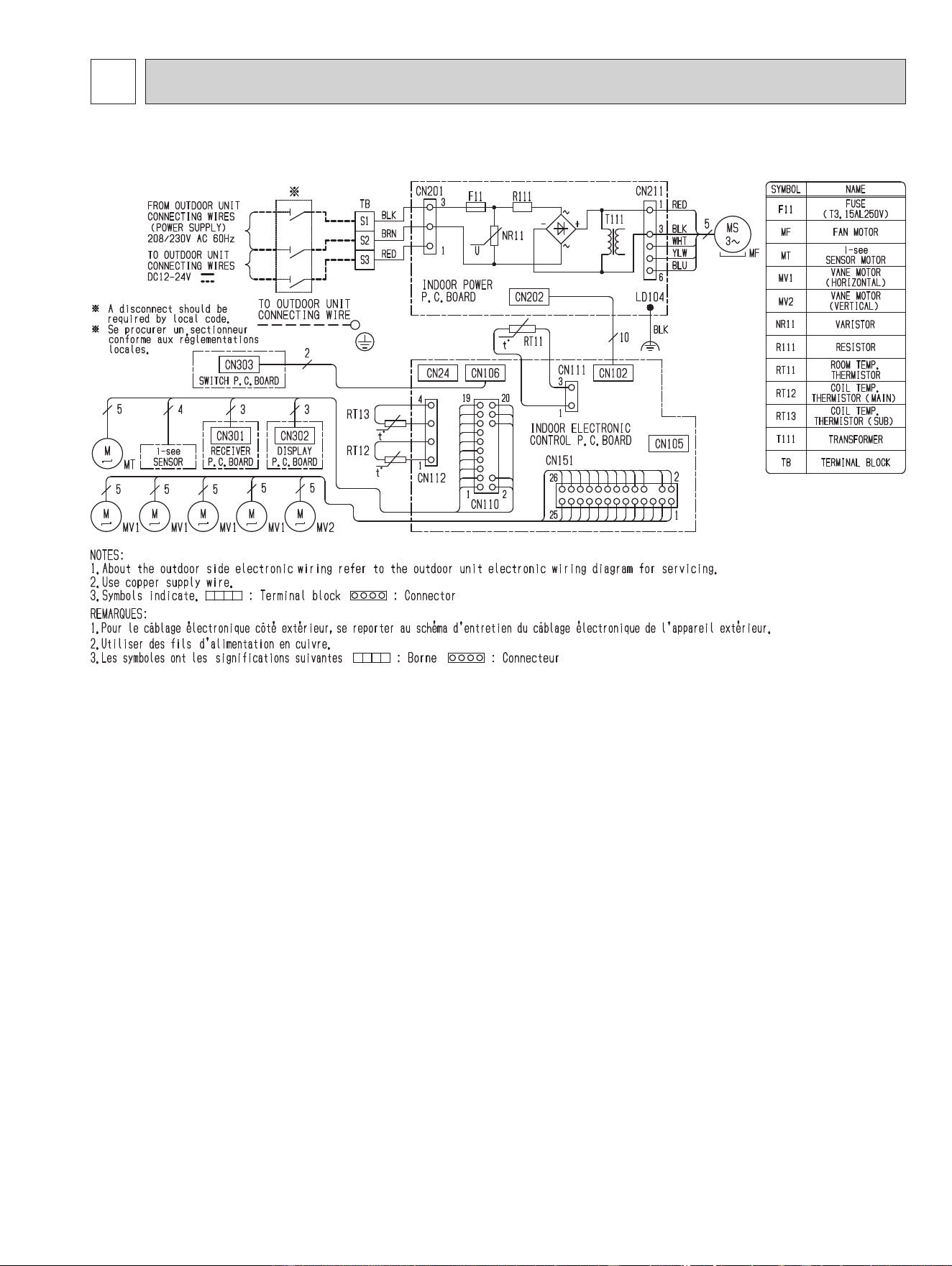
Use the specied refrigerant only
Never use any refrigerant other than that specified.
Doing so may cause a burst, an explosion, or fire when the unit is being used, serviced, or disposed of.
Correct refrigerant is specified in the manuals and on the spec labels provided with our products.
We will not be held responsible for mechanical failure, system malfunction, unit breakdown or accidents caused by
failure to follow the instructions.
OBH872
3
1
TECHNICAL CHANGES
MSZ-FS06NA -
U1
MSZ-FS09NA -
U1
MSZ-FS12NA -
U1
MSZ-FS15NA -
U1
MSZ-FS18NA -
U1
1. New model
OBH872
4
2
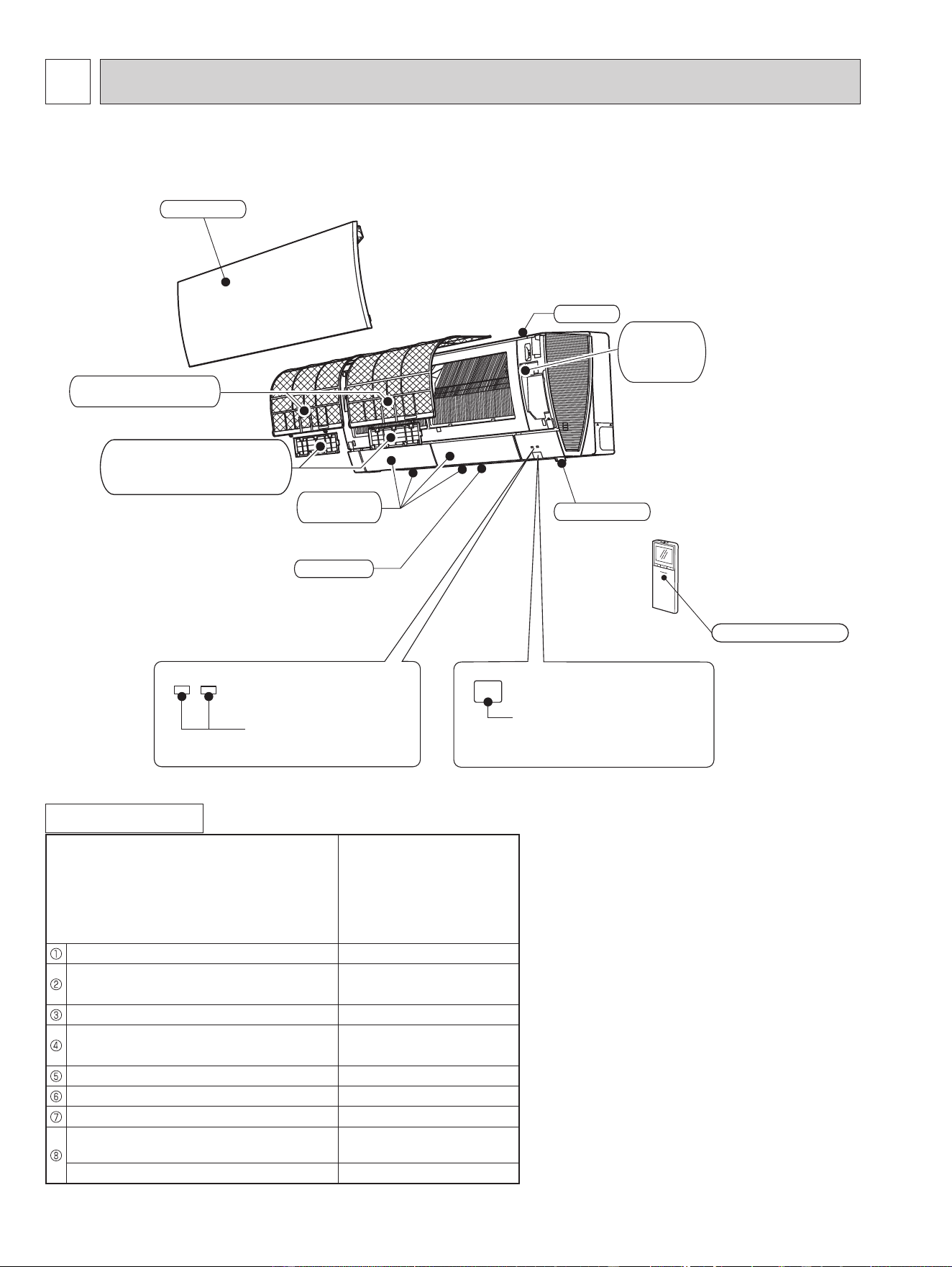
PART NAMES AND FUNCTIONS
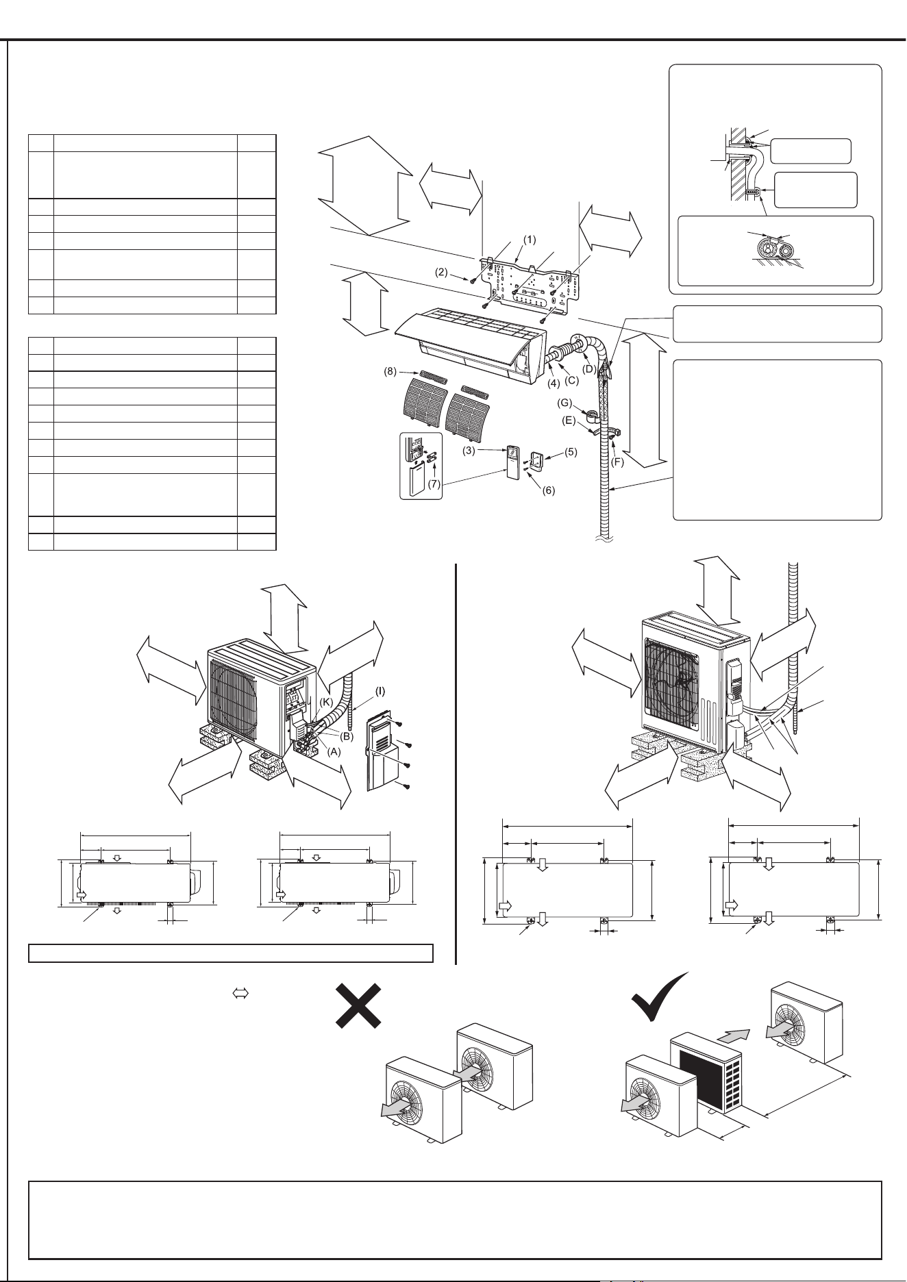
ACCESSORIES
Model
MSZ-FS06NA
MSZ-FS09NA
MSZ-FS12NA
MSZ-FS15NA
MSZ-FS18NA
Installation plate 1
Attachment screws for the installation
plate 4 × 25 mm
5
Remote controller holder 1
Screw for the remote controller holder
3.5 × 16 mm (Black)
2
Battery (AAA) for the remote controller 2
Wireless remote controller 1
Felt tape (For left or left-rear piping) 1
Air cleaning lter
(Electrostatic anti-allergy enzyme lter)
1
Air cleaning lter (Deodorizing lter) 1
Operation indicator lamp
Remote control receiving
section
Emergency
operation
switch
Horizontal
vane
Air inlet
Air filter
(Nano platinum filter)
Air cleaning filter
(Electrostatic anti-allergy
enzyme filter and deodorizing fiter)
Front panel
Air outlet
i-see sensor
Remote controller
MSZ-FS06NA MSZ-FS09NA MSZ-FS12NA MSZ-FS15NA MSZ-FS18NA
OBH872
5
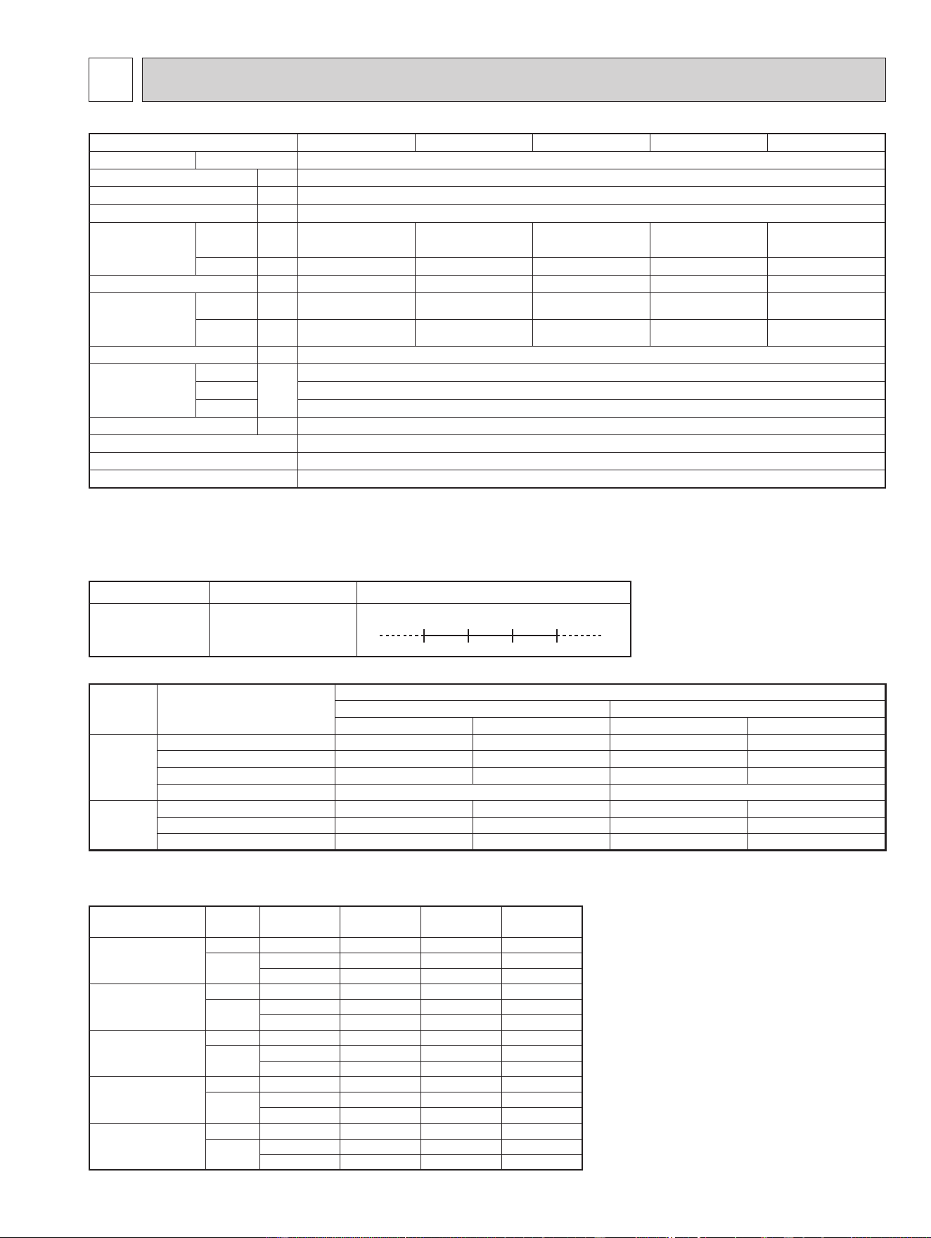
3
SPECIFICATION
3-2. OUTLET AIR SPEED AND COVERAGE
● The air coverage is the figure up to the
position where the air speed is 1 ft./s,
when air is blown out horizontally from
the unit properly at the High speed
position.
The coverage should be used only
as a general guideline since it varies
according to the size of the room and
furniture arranged inside the room.
(2) OPERATION
Mode Condition
Intake air temperature (°F)
Indoor Outdoor
DB WB DB WB
Cooling
Standard temperature 80 67 95 —
Maximum temperature 90 73 115 —
Minimum temperature 67 57 14 —
Maximum humidity 78% —
Heating
Standard temperature 70 60 47 43
Maximum temperature 80 67 75 65
Minimum temperature 70 60 -13 -14
3-1. OPERATING RANGE
(1) POWER SUPPLY
Rated voltage Guaranteed voltage (V)
Indoor unit
208/230 V
1 phase
60 Hz
Min. 187
208 230 Max. 253
Model Mode Function
Airow
(CFM)
Air speed
(ft./s)
Coverage
(ft.)
MSZ-FS06NA
HEAT Dry 437 19.5 29.8
COOL
Dry 381 17.0 26.1
Wet 328 14.6 22.5
MSZ-FS09NA
HEAT Dry 437 19.5 29.8
COOL
Dry 381 17.0 26.1
Wet 328 14.6 22.5
MSZ-FS12NA
HEAT Dry 454 20.3 31.0
COOL
Dry 424 19.0 29.0
Wet 364 16.2 24.8
MSZ-FS15NA
HEAT Dry 514 23.0 34.9
COOL
Dry 437 19.5 29.8
Wet 376 16.7 25.6
MSZ-FS18NA
HEAT Dry 514 23.0 34.9
COOL
Dry 437 19.5 29.8
Wet 376 16.7 25.6
Indoor unit model
MSZ-FS06NA MSZ-FS09NA MSZ-FS12NA MSZ-FS15NA MSZ-FS18NA
Power supply V, phase, Hz 208/230 , 1 , 60
Disconnect switch A 15
Min. circuit ampacity A 1.0
Fan motor F.L.A 0.65
Airow
Super high - High -
Med. - Low - Quiet
COOL Dry
(Wet)
CFM
381- 304 - 221 - 167 - 137
(328 - 261 - 190 - 143 - 117)
381- 304 - 221 - 167 - 137
(328 - 261 - 190 - 143 - 117)
424 - 304 - 221 - 167 - 137
(364- 261 - 190 - 143 - 117)
437 - 355 - 304 - 262 - 225
(376 - 305 - 261 - 225 - 194)
437 - 355 - 304 - 262 - 225
(376 - 305 - 261 - 225 - 194)
HEAT Dry
CFM
437 - 381 - 225 - 167 - 140 437 - 381 - 225 - 167 - 140 454 - 367 - 282 - 226 - 155 514 - 410 - 350 - 272 - 201 514 - 410 - 350 - 272 - 201
Moisture removal pt./h 0.2 0.6 1.9 4.0 5.1
Sound level
Super high - High -
Med. - Low - Quiet
Cooling
dB(A)
40 - 36 - 29 - 23 - 20 40 - 36 - 29 - 23 - 20 44 - 36 - 29 - 24 - 21 44 - 39 - 35 - 31 - 27 44 - 39 - 35 - 31 - 27
Heating
dB(A)
42 - 39 - 29 - 24 - 20 42 - 39 - 29 - 24 - 20 43 - 38 - 32 - 28 - 21 46 - 40 - 37 - 31 - 25 46 - 40 - 37 - 31 - 25
Cond. drain connection O.D.
in. 5/8
Dimensions
W
in.
36-7/16
D 9-3/16
H 12 (+ 11/16)
Weight Ib. 29
External nish Munsell 1.0Y 9.2/0.2
Remote controller Wireless type
Control voltage (by built-in transformer)
12 - 24 VDC
NOTE: Test conditions are based on AHRI 210/240.
OBH872
6
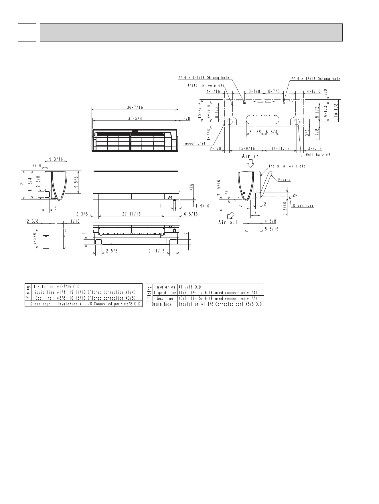
4
OUTLINES AND DIMENSIONS
Unit: inch
MSZ-FS06NA MSZ-FS09NA MSZ-FS12NA MSZ-FS15NA MSZ-FS18NA
(MSZ-FS06/09/12NA)
(MSZ-FS15/18NA)
OBH872
7
5
WIRING DIAGRAM
MSZ-FS06NA MSZ-FS09NA MSZ-FS12NA MSZ-FS15NA MSZ-FS18NA
OBH872

8
6
REFRIGERANT SYSTEM DIAGRAM
Indoor
heat
exchanger
Flared connection
Room temperature
thermistor
RT11
Flared connection
Refrigerant pipe ø3/8 (ø9.52)
(with heat insulator)
Refrigerant pipe ø1/4 (ø6.35)
(with heat insulator)
Indoor coil
thermistor
RT12 (main)
Indoor coil
thermistor
RT13 (sub)
Refrigerant flow in cooling
Refrigerant flow in heating
Unit: inch (mm)
Indoor
heat
exchanger
Flared connection
Room temperature
thermistor
RT11
Flared connection
Refrigerant pipe ø1/2 (ø12.7)
(with heat insulator)
Refrigerant pipe ø1/4 (ø6.35)
(with heat insulator)
Indoor coil
thermistor
RT12 (main)
Indoor coil
thermistor
RT13 (sub)
Refrigerant flow in cooling
Refrigerant flow in heating
MSZ-FS15NA MSZ-FS18NA
MSZ-FS06NA MSZ-FS09NA MSZ-FS12NA
OBH872
9
7
SERVICE FUNCTIONS
7-1. TIMER SHORT MODE
For service, the following set time can be shortened by bridging JPG and JPS on the electronic control P.C. board.
(Refer to 9-7.)
Set time: 3 minutes → 3 seconds (It takes 3 minutes for the compressor to start operation. However, the starting time is
shortened by bridging JPG and JPS.)
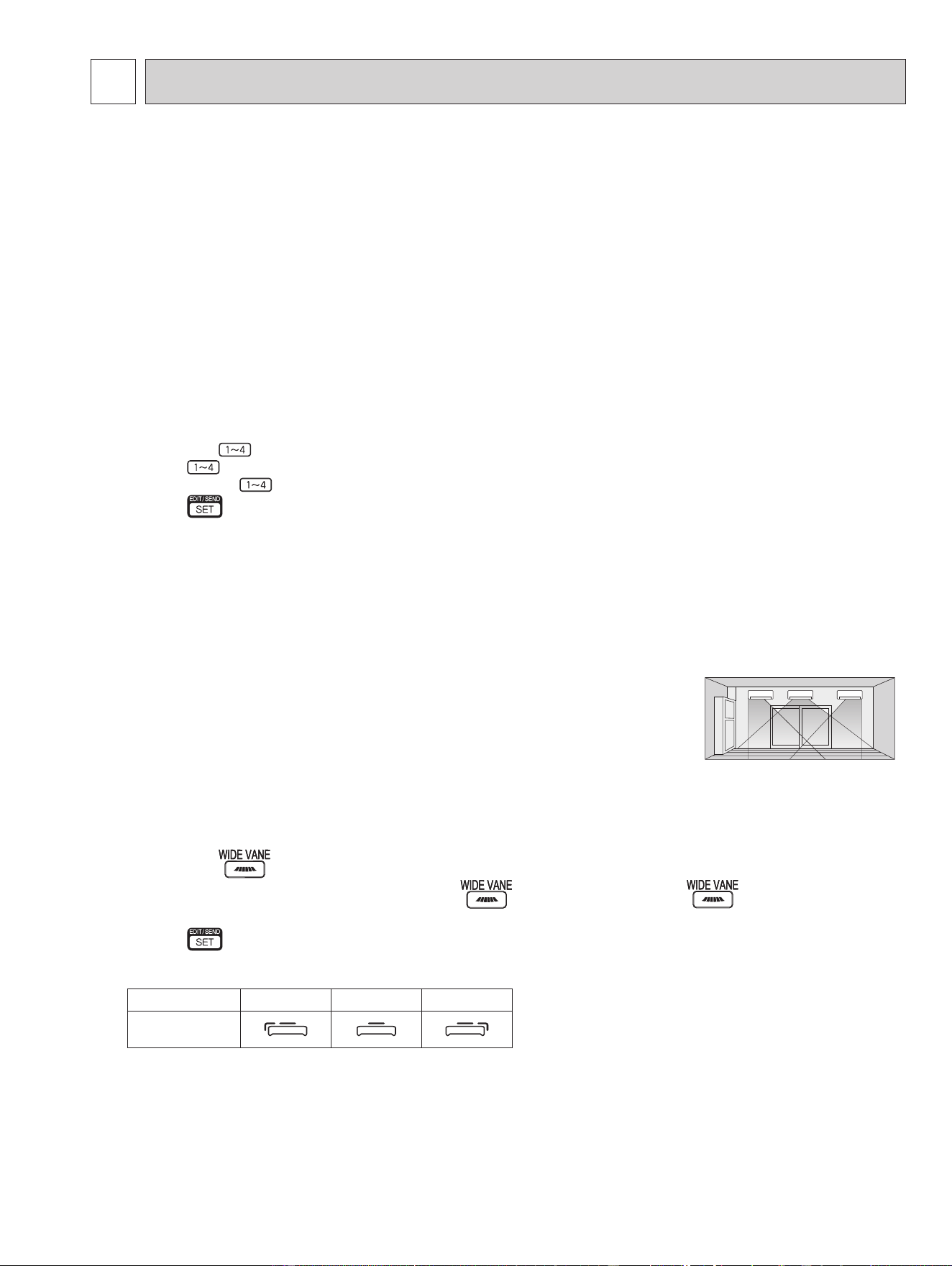
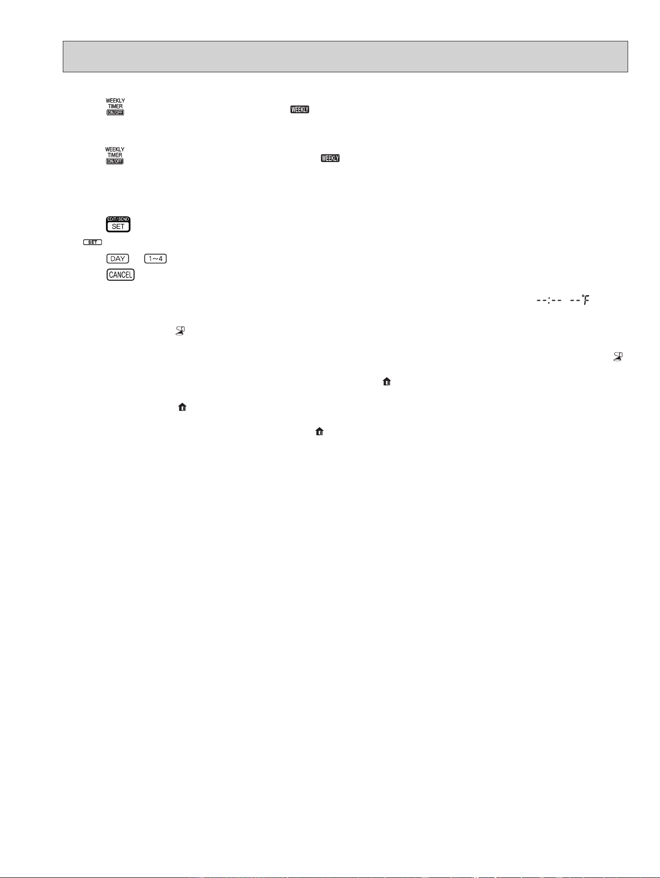
7-2. HOW TO SET REMOTE CONTROLLER EXCLUSIVELY FOR A PARTICULAR INDOOR UNIT
A maximum of 4 indoor units with wireless remote controllers can be used in a room.
To operate the indoor units individually with each remote controller, assign a number to each remote controller according
to the number of the indoor unit.
This setting can be set only when all the following conditions are met:
• The remote controller is powered OFF.
• Weekly timer is not set.
• Weekly timer is not being edited.
(1) Hold down
button on the remote controller for 2 seconds to enter the pairing mode.
(2) Press
button again and assign a number to each remote controller.
Each press of
button advances the number in the following order: 1 → 2 → 3 → 4.
(3) Press
button to complete the pairing setting.
After you turn the breaker ON, the remote controller that first sends a signal to an indoor unit will be regarded as the
remote controller for the indoor unit.
Once they are set, the indoor unit will only receive the signal from the assigned remote controller afterwards.
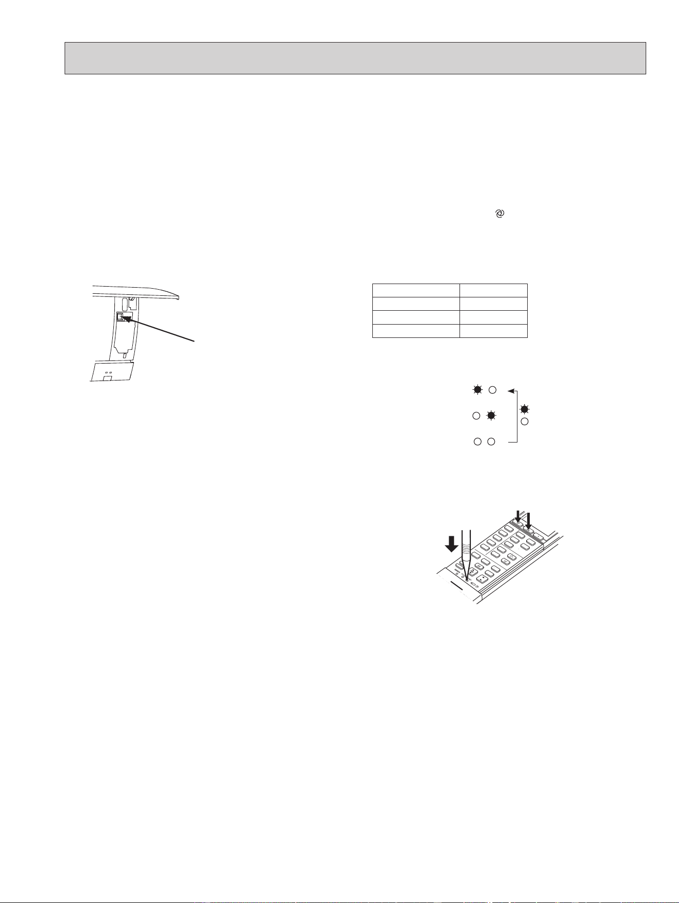
7-3. SETTING THE INSTALLATION POSITION
Be sure to set the remote controller according to the installed position of the indoor unit.
Installation position:
Left: Distance to objects (wall, cabinet, etc.) is less than 50 cm to the left
Center: Distance to objects (wall, cabinet, etc.) is more than 50 cm to the left and right
Right: Distance to objects (wall, cabinet, etc.) is less than 50 cm to the right
The installation position can be set only when all the following conditions are met:
• The remote controller is powered OFF.
• Weekly timer is not set.
• Weekly timer is not being edited.
(1) Hold down
button on the remote controller for 2 seconds to enter the position setting mode.
(2) Select the target installation position by pressing
button. (Each press of the button displays the
positions in order: center → right → left.)
(3) Press
button to complete the position setting.
Installation position Left Center Right
Remote controller
display
(Left)(Center)(Right)
MSZ-FS06NA MSZ-FS09NA MSZ-FS12NA MSZ-FS15NA MSZ-FS18NA
OBH872
10
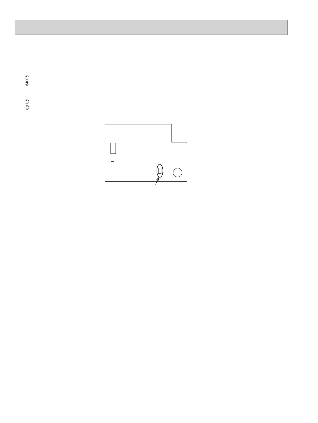
7-4. AUTO RESTART FUNCTION
When the indoor unit is controlled with the remote controller, the operation mode, the set temperature, and the fan speed
are memorized by the indoor electronic control P.C. board. “AUTO RESTART FUNCTION” automatically starts operation in
the same mode just before the shutoff of the main power.
Operation
If the main power has been cut, the operation settings remain.
After the power is restored, the unit restarts automatically according to the memory.
(However, it takes at least 3 minutes for the compressor to start running.)
How to disable “AUTO RESTART FUNCTION”
Turn off the main power for the unit.
Cut the jumper wire to JR77 on the indoor electronic control P.C. board. (Refer to 9-7.)
NOTE:
•
The operation settings are memorized when 10 seconds have passed after the indoor unit was operated with the remote
controller.
• If main power is turned OFF or a power failure occurs while AUTO START/STOP timer is active, the timer setting is can-
celled.
• If the unit has been off with the remote controller before power failure, the auto restart function does not work as the
power button of the remote controller is OFF.
• To prevent breaker OFF due to the rush of starting current, systematize other home appliance not to turn ON at the same
time.
• When some air conditioners are connected to the same supply system, if they are operated before power failure, the
starting current of all the compressors may flow simultaneously at restart.
Therefore, the special counter-measures are required to prevent the main voltage-drop or the rush of the starting current
by adding to the system that allows the units to start one by one.
JR77
CN110CN151
BZ
Indoor electronic control
P.C. board
OBH872
11
8
MICROPROCESSOR CONTROL
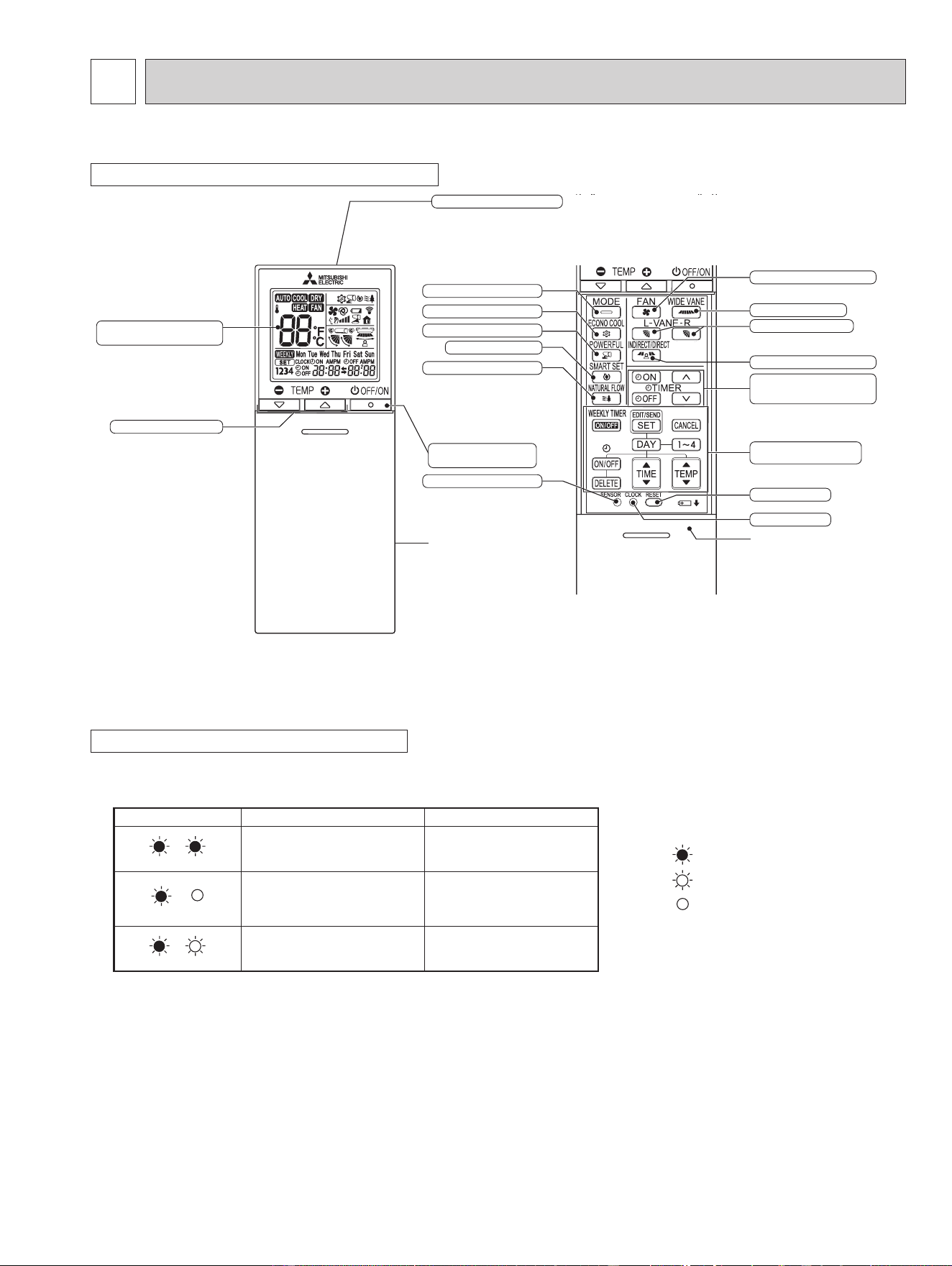
WIRELESS REMOTE CONTROLLER
NOTE: Last setting will be stored after the unit is turned OFF with the remote controller. Indoor unit receives the signal of the
remote controller with beeps.
INDOOR UNIT DISPLAY SECTION
Operation Indicator lamp
The operation indicator at the right side of the indoor unit indicates the operation state.
•The following indication applies regardless of shape of the indication.
Indication Operation state Room temperature
The unit is operating to
reach the set temperature.
About 4°F (2°C) or more
away from set temperature
The room temperature is
approaching the set tem-
perature.
About 2 to 4°F (1 to 2°C)
from set temperature
Standby mode (only during
multisystem operation)
—
Lighted
Blinking
Not lighted
MSZ-FS06NA MSZ-FS09NA MSZ-FS12NA MSZ-FS15NA MSZ-FS18NA
Signal transmitting section
Operation display section
(Backlight display*)
Temperature buttons
OFF/ON
(stop/operate) button
Indication of
remote controller
model is on back
Distance of signal :
About 20 ft. (6 m)
Beep(s) is (are) heard from
the indoor unit when the
signal is received.
FAN speed control button
INDIRECT/DIRECT button
ECONO COOL button
POWERFUL button
CLOCK button
Lid
Slide the lid down
to open the remote
controller. Slide it down
further to get to the
weekly timer buttons.
TIME, WEEKLY TIMER
set buttons
TIME, TIMER set buttons
forward button
backward button
RESET button
SMART SET button
NATURAL FLOW button
SENSOR (i-see) button
VANE control button
WIDE VANE button
Operation select button
* The backlight turns on when using the remote controller.
The backlight goes o if the remote controller is not used for a while.
OBH872

12
8-4. HEAT ( ) OPERATION
(1) Press OFF/ON (stop/operate) button.
OPERATION INDICATOR lamp of the indoor unit turns on with a beep tone.
(2) Select HEAT mode with Operation select button.
(3) Press Temperature buttons TEMP
or button to select the desired temperature.
The setting range is 61 - 88°F (16 - 31°C).
1. Cold air prevention control
When the compressor is not operating or is starting, and the temperature of indoor heat exchanger and/or the room tem-
perature is low or when defrosting is being done, the indoor fan will stop or rotate in Very Low speed.
2. High pressure protection
The compressor operational frequency is controlled by the temperature of the indoor heat exchanger to prevent the con-
densing pressure from increasing excessively.
When the temperature of indoor heat exchanger becomes too high, the high pressure protection works.
The indoor fan operates following the cold air prevention control. This mode continues until the temperature of indoor
heat exchanger falls.
3. Defrosting
Defrosting starts when the temperature of outdoor heat exchanger becomes too low.
The compressor stops once, the indoor/outdoor fans stop, the 4-way valve reverses, and the compressor re-starts.
This mode continues until the temperature of outdoor heat exchanger rises or the fixed time passes.
8-2. DRY ( ) OPERATION
(1) Press OFF/ON (stop/operate) button. OPERATION INDICATOR lamp of the indoor unit turns on with a beep tone.
(2) Select DRY mode with Operation select button.
(3) The set temperature is determined from the initial room temperature.
1. Coil frost prevention
Coil frost prevention works the same way as that in COOL mode. (8-1.1.)
2. Low outside temperature operation
Low outside temperature operation works the same way as that in COOL mode. (8-1.2.)
8-3. FAN ( ) OPERATION
(1) OPERATION INDICATOR lamp of the indoor unit turns on with a beep tone.
(2) Select FAN mode with Operation select button.
(3) Select the desired fan speed. When AUTO, it becomes Low.
Only indoor fan operates.
Outdoor unit does not operate.
8-1. COOL ( ) OPERATION
(1) Press OFF/ON (stop/operate) button. OPERATION INDICATOR lamp of the indoor unit turns on with a beep tone.
(2) Select COOL mode with Operation select button.
(3) Press Temperature buttons TEMP
or button to select the desired temperature.
The setting range is 61 - 88°F (16 - 31°C).
1. Coil frost prevention
The compressor operational frequency is controlled by the temperature of the indoor heat exchanger to prevent the coil
from frosting.
When the temperature of indoor heat exchanger becomes too low, the coil frost prevention mode works.
The indoor fan operates at the set speed and the compressor stops. This mode continues until the temperature of indoor
heat exchanger rises.
2. Low outside temperature operation
When the outside temperature is lower, low outside temperature operation starts, and the outdoor fan slows or stops.
8-5. AUTO CHANGE OVER ∙∙∙ AUTO MODE OPERATION
Once desired temperature is set, unit operation is switched automatically between COOL and HEAT operation.
Mode selection
(1) Initial mode
When unit starts the operation with AUTO operation from OFF:
• If the room temperature is higher than the set temperature, operation starts in COOL mode.
• If the room temperature is equal to or lower than the set temperature, operation starts in HEAT mode.
(2) Mode change
COOL mode changes to HEAT mode when about 15 minutes have passed with the room temperature 2°F (1°C) below
the set temperature.
HEAT mode changes to COOL mode when about 15 minutes have passed with the room temperature 2°F (1°C) above
the set temperature.
OBH872
13
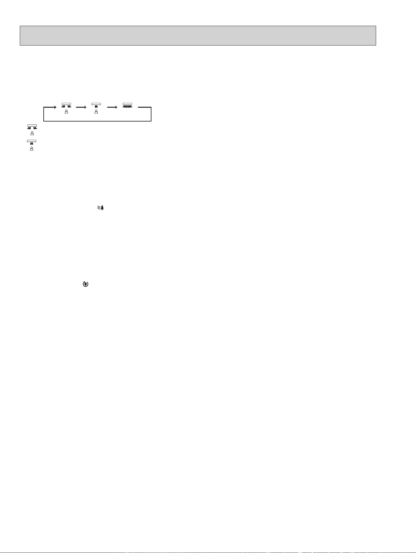
8-6. AUTO VANE OPERATION
1. Horizontal vane
(1) Vane motor drive
These models are equipped with a stepping motors for the horizontal vanes. The rotating direction, speed, and angle
of the motor are controlled by pulse signals (approximately 12 V) transmitted from indoor microprocessor.
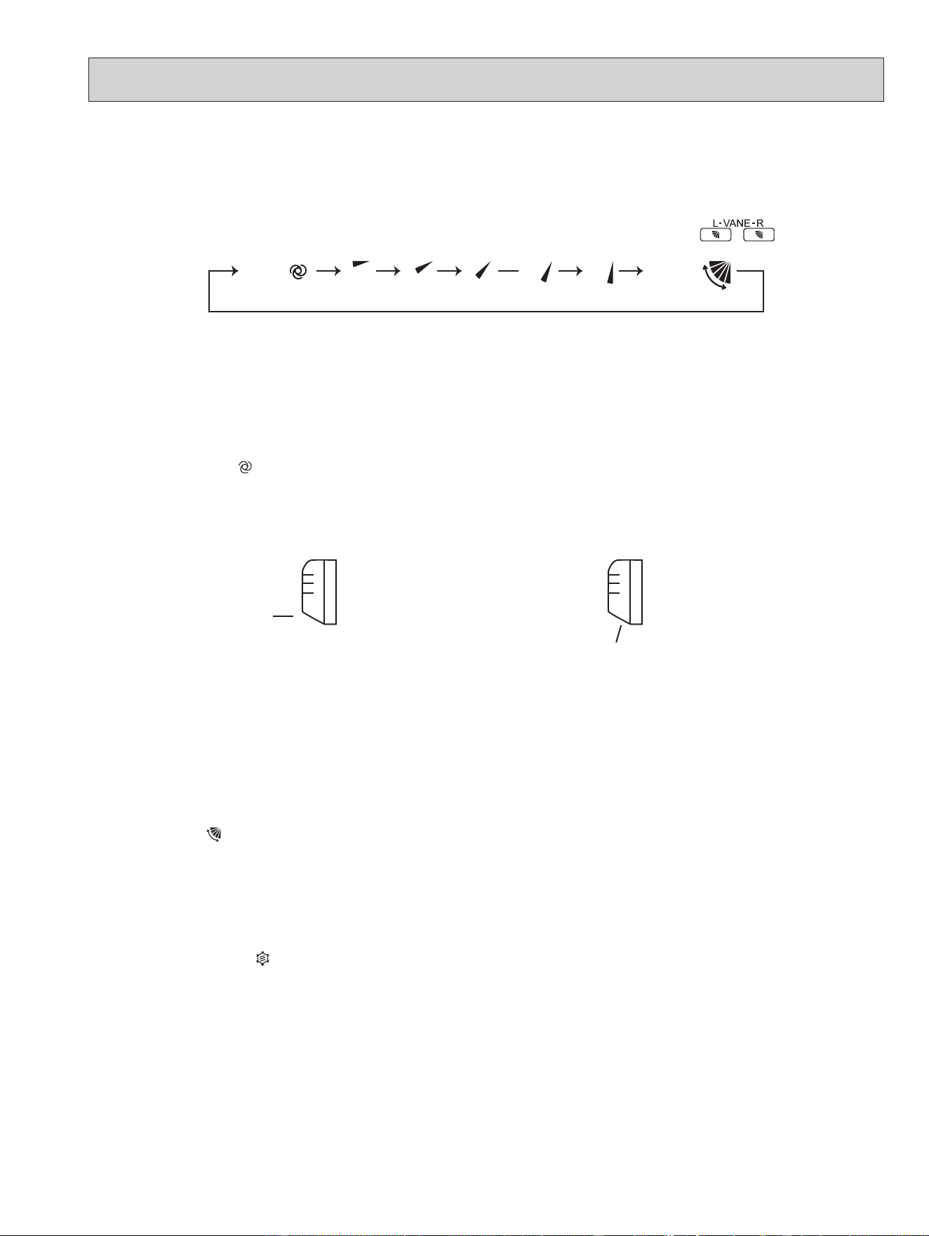
(2) The horizontal vane angle and mode change as follows by pressing VANE CONTROL (
) button.
AUTO 1 2 5 SWING43
(AUTO) (1) (2) (3) (4) (5) (SWING)
NOTE: The right and left horizontal vanes set to the same level may not align perfectly.
(7) SWING (
) mode
By selecting SWING mode with VANE control button, the horizontal vanes swing vertically.
When COOL, DRY or FAN mode is selected, only the upper vane swings.
(8) Cold air prevention in HEAT operation
The horizontal vane position is set to upward.
NOTE: When 2 or more indoor units are operated with multi outdoor unit, even if any indoor unit turns thermostat off,
this control does not work in the indoor unit.
(9) ECONO COOL (
) operation (ECONOmical operation)
When ECONO COOL button is pressed in COOL mode, set temperature is automatically set 4°F (2°C) higher by the
microprocessor. However, the temperature on the LCD screen on the remote controller is not changed. Also the hori-
zontal vane swings in various cycle.
SWING operation makes you feel cooler than set temperature. So, even though the set temperature is higher, the air
conditioner can keep comfort. As a result, energy can be saved.
To cancel this operation, select a different mode or press one of the following buttons in ECONO COOL operation:
ECONO COOL, VANE control, POWERFUL or NATURAL FLOW button.
Horizontal
position
4
In COOL and DRY operation
Vane angle is fixed to Horizontal position.
In HEAT operation
Vane angle is fixed to Angle 4.
(5) STOP (operation OFF) and ON TIMER standby
In the following cases, the horizontal vane returns to the closed position.
(a) When OFF/ON (stop/operate) button is pressed (POWER OFF).
(b) When the operation is stopped by the emergency operation.
(c) When ON TIMER is ON standby.
(6) Dew prevention
During COOL or DRY operation with the vane angle at Angle 4 or 5 when the compressor cumulative operation time
exceeds 1 hour, the vane angle automatically changes to Angle 3 for dew prevention.
(3) Positioning
To confirm the standard position, the vane move until it touches the vane stopper. Then the vane is set to the select-
ed angle.
Confirming of standard position is performed in the following cases:
(a) When the operation starts or finishes (including timer operation).
(b) When the test run starts.
(c) When standby mode (only during multi system operation) starts or finishes.
(4) VANE AUTO (
) mode
In VANE AUTO mode, the microprocessor automatically determines the vane angle to make the optimum room tem-
perature distribution.
OBH872
14
(10) POWERFUL (
) operation
The air conditioner automatically adjusts the fan speed and the set temperature, and operates the POWERFUL mode.
The POWERFUL mode is cancelled automatically 15 minutes after operation starts, or when POWERFUL button
is pressed once again within 15 minutes after operation starts. The operation mode returns to the mode prior to
POWERFUL operation. POWERFUL mode also is cancelled, when the OFF/ON (stop/operate), ECONO COOL,
FAN
speed control, NATURAL FLOW or SMART SET button is pressed within 15 minutes after operation starts, or operation
mode is changed.
2. Vertical vane
(1) Vane motor drive
These models are equipped with a stepping motor for the vertical vane. The rotating direction, speed, and angle of
the motor are controlled by pulse signals (approximately 12 V) transmitted from microprocessor.
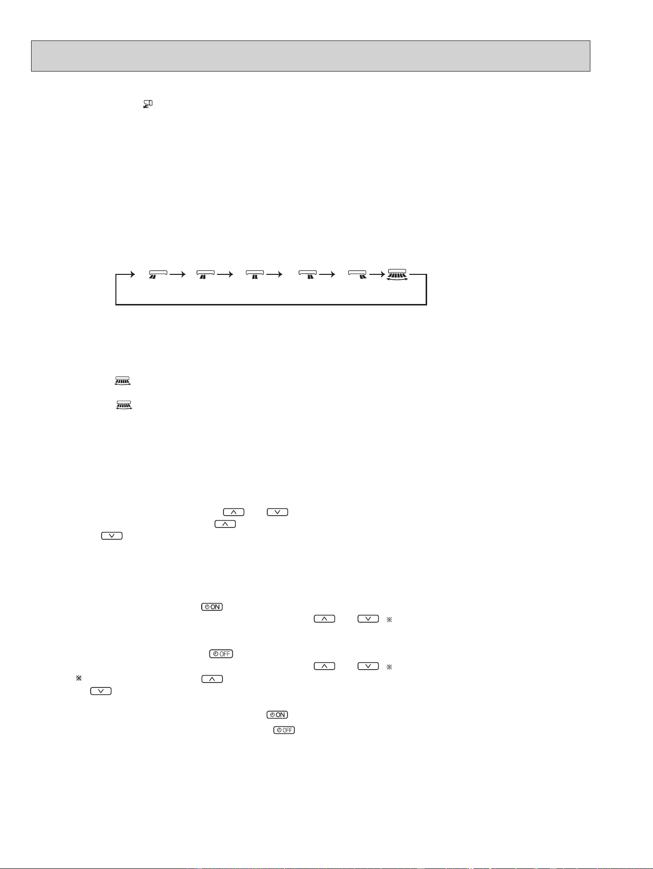
(2) The vertical vane angle and mode change as follows by pressing WIDE VANE button.
(3) Positioning
To confirm the standard position, the vane moves until it touches the vane stopper. Then the vane is set to the select-
ed angle.
Confirming of standard position is performed in the following cases:
(a) OFF/ON (stop/operate) button is pressed (POWER ON).
1 2 3 4 5
(SWING)
(4) SWING ( ) MODE
By selecting SWING mode with WIDE VANE button, the vertical vane swings horizontally. The remote controller
displays “
”. Swing mode is cancelled when WIDE VANE button is pressed once again.
8-7. TIMER OPERATION
1. How to set the time
(1) Check that the current time is set correctly.
NOTE: Timer operation will not work without setting the current time. Initially “12:00 AM” blinks at the current time
display of TIME MONITOR, so set the current time correctly with CLOCK button.
How to set the current time
(a) Press the CLOCK button.
(b) Press the TIME SET buttons (
and ) to set the current time.
• Each time forward button (
) is pressed, the set time increases by 1 minute, and each time backward button
( ) is pressed, the set time decreases by 1 minute.
• Pressing those buttons longer, the set time increases/decreases by 10 minutes.
(c) Press the CLOCK set button.
(2) Press OFF/ON (stop/operate) button to start the air conditioner.
(3) Set the time of timer.
ON timer setting
(a) Press ON TIMER button(
) during operation.
(b) Set the time of the timer using TIME SET buttons ( and ).
OFF timer setting
(a) Press OFF TIMER button (
) during operation.
(b) Set the time of the timer using TIME SET buttons ( and ).
Each time forward button ( ) is pressed, the set time increases by 10 minutes: each time backward
button
(
) is pressed, the set time decreases by 10 minutes.
2. To release the timer
To release ON timer, press ON TIMER button (
).
To release OFF timer, press OFF TIMER button(
).
TIMER is cancelled and the display of set time disappears.
OBH872
15
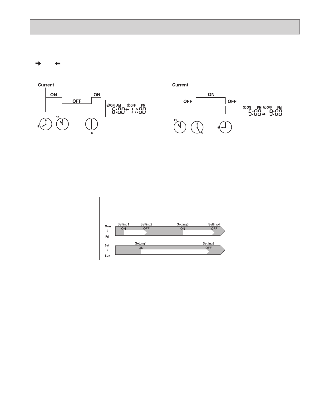
8-8. WEEKLY TIMER OPERATION
E.g. : Runs at 75°F (24°C) from waking up to leaving home,
and runs at 81°F (27°C) from getting home to going to
bed on weekdays.
Runs at 81°F (27°C) from waking up late to going bed
early on weekends.
75°F (24°C)
81°F (27°C)
PM 5:30AM 6:00 AM 8:30 PM 10:00
PM 9:00PM 8:00
81°F (27°C)
• A maximum of 4 ON or OFF timers can be set for individual days of the week.
• A maximum of 28 ON or OFF timers can be set for a week.
NOTE:
• The simple ON/OFF timer setting is available while the weekly timer is on. In this case, the ON/OFF timer has priority over the
weekly timer; the weekly timer operation will start again after the simple ON/OFF timer is complete.
• When the weekly timer is set, temperature can not be set to 50°F (10°C).
• The weekly timer operation and SMART SET operation cannot be used together.
(Example 1) The current time is 8:00 PM.
The unit turns off at 11:00 PM, and on at 6:00 AM.
• OFF timer and ON timer can be used in combination. The set time that is reached first will operate first.
• “
” and “ ” display shows the order of OFF timer and ON timer operation.
PROGRAM TIMER
(Example 2) The current time is 11:00 AM.
The unit turns on at 5:00 PM, and off at 9:00 PM.
NOTE: If the main power is turned OFF or a power failure occurs while ON/OFF timer is active, the timer setting is can-
celled. As these models are equipped with an auto restart function, the air conditioner starts operating with timer
cancelled when power is restored.
OBH872
16
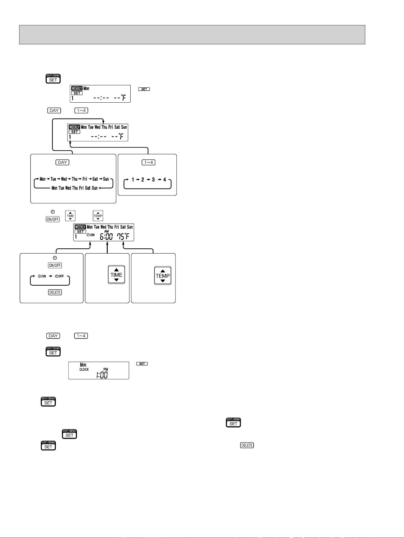
* Make sure that the current time and day are set correctly.
(1) Press button to enter the weekly timer setting mode.
(2) Press
and buttons to select setting day and number.
(3) Press , , and buttons to set ON/OFF, time, and temperature.
E.g. : [ON], [AM 6:00] and
[75°F (24°C)] are
selected.
Pressing
selects ON/OFF timer.
Pressing
deletes timer setting.
Pressing
adjusts the time.
Pressing
adjusts the tem-
perature.
* Hold down the button to change the time quickly.
* The temperature can be set between 61°F and 88°F (16°C and 31°C) at weekly timer.
*
blinks.
Pressing selects the day of
the week to be set.
Pressing selects
the setting number.
E.g. : [Mon Tue ... Sun]
and [1] are selected.
* All days can be selected.
1. How to set the weekly timer
Press and buttons to continue setting the timer for other days and/or numbers.
NOTE:
• Press
button to transmit the setting information of weekly timer to the indoor unit. Point the remote controller toward the
indoor unit for 3 seconds.
• When setting the timer for more than one day of the week or one number,
button does not have to be pressed per each
setting. Press
button once after all the settings are complete. All the weekly timer settings will be saved.
• Press
button to enter the weekly timer setting mode, and press and hold button for 5 seconds to erase all weekly
timer settings. Point the remote controller toward the indoor unit.
(4) Press
button to complete and transmit the weekly timer setting.
* which was blink-
ing goes out, and the
current time will be
displayed.
OBH872
17
8-9. i-see CONTROL ( ) MODE
In the i-see control mode, the room temperature is controlled based on the sensible temperature.
(1)
Press SENSOR button with a thin instrument during COOL, DRY, HEAT and AUTO mode to activate i-see control mode ( ).
The default setting is “active”.
(2) Press SENSOR button again to activate ABSENCE DETECTION (
).
(3) Press SENSOR button again to release i-see control mode.
ABSENCE DETECTION (
)
This function automatically changes the operation to energy-saving operation when nobody is in the room.
(1) To activate this function, press SENSOR button until
appears on the operation display of the remote controller during the
i-see control mode.
(2) Press SENSOR button again to release ABSENCE DETECTION.
2. Checking weekly timer setting
(1) Press button to enter the weekly timer setting mode.
*
blinks.
(2) Press
or buttons to view the setting of the particular day or number.
(3) Press
button to exit the weekly timer setting.
NOTE:
When all days of the week are selected to view the settings and a dierent setting is included among them,
will be
displayed.
(5) Press
button to turn the weekly timer ON. ( lights.)
•When the weekly timer is ON, the day of the week whose timer setting is complete, will light.
Press
button again to turn the weekly timer OFF. ( goes out.)
NOTE:
The saved settings will not be cleared when the weekly timer is turned OFF.
NOTE:
Any person at the following places cannot be detected:
• Along the wall on which the air conditioner is installed
• Directly under the air conditioner
• Where any obstacle, such as furniture, is between the person and the air conditioner
A person may not be detected in the following situations:
• Room temperature is high.
• A person wears heavy clothes and his/her skin is not exposed.
• A heating element of which temperature changes signicantly is present.
• Some heat sources, such as a small child or pet, may not be sensed.
• A heat source and the air conditioner are more than 20 ft. (6 m) apart.
• A heat source does not move for a long time.
OBH872
18
8-11. NATURAL FLOW ( ) OPERATION
In NATURAL FLOW operation, air ow will become more like natural wind. An occupant will not be directly exposed to the
air ow and feel more comfortable.
(1) Press NATURAL FLOW button during COOL or FAN mode to start NATURAL FLOW operation.
(2) Press NATURAL FLOW button again to cancel NATURAL FLOW operation.
• NATURAL FLOW operation is also cancelled when the POWERFUL or ECONO COOL button is pressed.
NOTE: As the fan speed changes constantly during NATURAL FLOW operation, the sound of air ow, wind velocity and air ow
temperature also change. This is not a malfunction.
8-12. SMART SET ( ) OPERATION
1. How to set SMART SET operation
(1) Press OFF/ON (stop/operate) button.
(2) Select COOL, HEAT or ECONO COOL mode.
(3) Press SMART SET button.
(4) Set the temperature, fan speed, and airow direction for SMART SET operation.
NOTE:
• SMART SET operation cannot be selected during DRY or AUTO mode operation.
• The setting range of HEAT mode SMART SET operation is 50°F (10°C) and 61 - 88°F (16 - 31°C).
• 2 groups of setting can be saved. (One for COOL/ECONO COOL, one for HEAT)
• SMART SET operation and the weekly timer operation cannot be used together.
2. How to cancel operation
• Press SMART SET button again.
• SMART SET operation can also be cancelled by pressing Operation select button to change the operation mode.
The same setting is select from the next time by simply pressing SMART SET button.
8-10. INDIRECT/DIRECT MODE
The INDIRECT/DIRECT mode oers nely-tuned operation by locating where an occupant is in the room.
(1) Press INDIRECT/DIRECT button during COOL, DRY, HEAT or AUTO mode to activate INDIRECT/DIRECT mode.
This mode is only available when the i-see control mode is eective.
(2) Each press of INDIRECT/DIRECT button changes INDIRECT/DIRECT in the following order:
(INDIRECT) : An occupant will be less exposed to direct airfl ow.
(DIRECT) : Mainly the vicinity of an occupant will be air-conditioned.
(INDIRECT) (DIRECT) (OFF)
NOTE:
• Horizontal and vertical airow directions will be automatically selected.
• If you still feel uncomfortable with the air direction determined by the INDIRECT mode, adjust the air direction manually.
• Cancelling the i-see control mode automatically cancels the INDIRECT/DIRECT mode.
INDIRECT/DIRECT mode is also cancelled when the VANE control or WIDE VANE buttons is pressed.
• Do not touch the i-see sensor. This may cause malfunction of the i-see sensor.
OBH872
19
8-13. EMERGENCY/TEST OPERATION
In the case of test run operation or the emergency operation, use the emergency operation switch on the right side of the
indoor unit. The emergency operation is available when the remote controller is missing or has failed, or when the batteries
in the remote controller are running down. The unit will start and OPERATION INDICATOR lamp will light up.
The first 30 minutes of operation is the test run operation. This operation is for servicing. The indoor fan runs at High
speed and the temperature control does not work.
After 30 minutes of test run operation, the system shifts to
EMERGENCY COOL/HEAT MODE with a set temperature of
75°F (24°C).
The fan speed shifts to Medium.
The coil frost prevention works even in the test run or the emergency operation.
In the test run or the emergency operation, the horizontal vane operates in VANE AUTO (
) mode.
The emergency operation continues until the emergency operation switch is pressed once or twice or the unit receives
any signal from the remote controller. In the latter case, normal operation will start.
NOTE: Do not press the emergency operation switch during normal operation.
Operation mode COOL/HEAT
Set temperature 75°F (24°C)
Fan speed Med.
Horizontal vane Auto
The operation mode is indicated by the Operation
Indicator lamp as following
Operation Indicator lamp
EMERGENCY COOL
↓
EMERGENCY HEAT
↓
STOP
Lighted
Not lighted
8-14. 3-MINUTE TIME DELAY OPERATION
When the system turns OFF, compressor will not restart for 3 minutes as 3-minute time delay function operates to protect
compressor from overload.
Emergency
operation switch
(E.O. SW)
8-15. Changing temperature indication (°F/°C)
• The preset unit is °F.
• °F → °C: Press RESET button while the Temperature buttons are pressed.
• °C → °F: Press RESET button or remove the batteries .
Press RESET button gently
using a thin instrument.
OBH872
20
9
TROUBLESHOOTING
9-1. CAUTIONS ON TROUBLESHOOTING
1. Before troubleshooting, check the following
1) Check the power supply voltage.
2) Check the indoor/outdoor connecting wire for miswiring.
2. Take care of the following during servicing
1) Before servicing the air conditioner, be sure to turn OFF the main unit first with the remote controller, and then after
confirming the horizontal vane is closed, turn OFF the breaker and/or disconnect the power plug.
2) Be sure to turn OFF the power supply before removing the front panel, the cabinet, the top panel, and the P.C. board.
3) When removing the P.C. board, hold the edge of the board with care NOT to apply stress on the components.
4) When connecting or disconnecting the connectors, hold the connector housing. DO NOT pull the lead wires.
3. Troubleshooting procedure
1) Check if the OPERATION INDICATOR lamp on the indoor unit is blinking ON and OFF to indicate an abnormality.
To make sure, check how many times the OPERATION INDICATOR lamp is blinking ON and OFF before starting ser-
vice work.
2) Before servicing, verify that all connectors and terminals are connected properly.
3) When the electronic control P.C. board seems to be defective, check for disconnection of the copper foil pattern and
burnt or discolored components.
4) When troubleshooting, Refer to 9-2, 9-3 and 9-4.
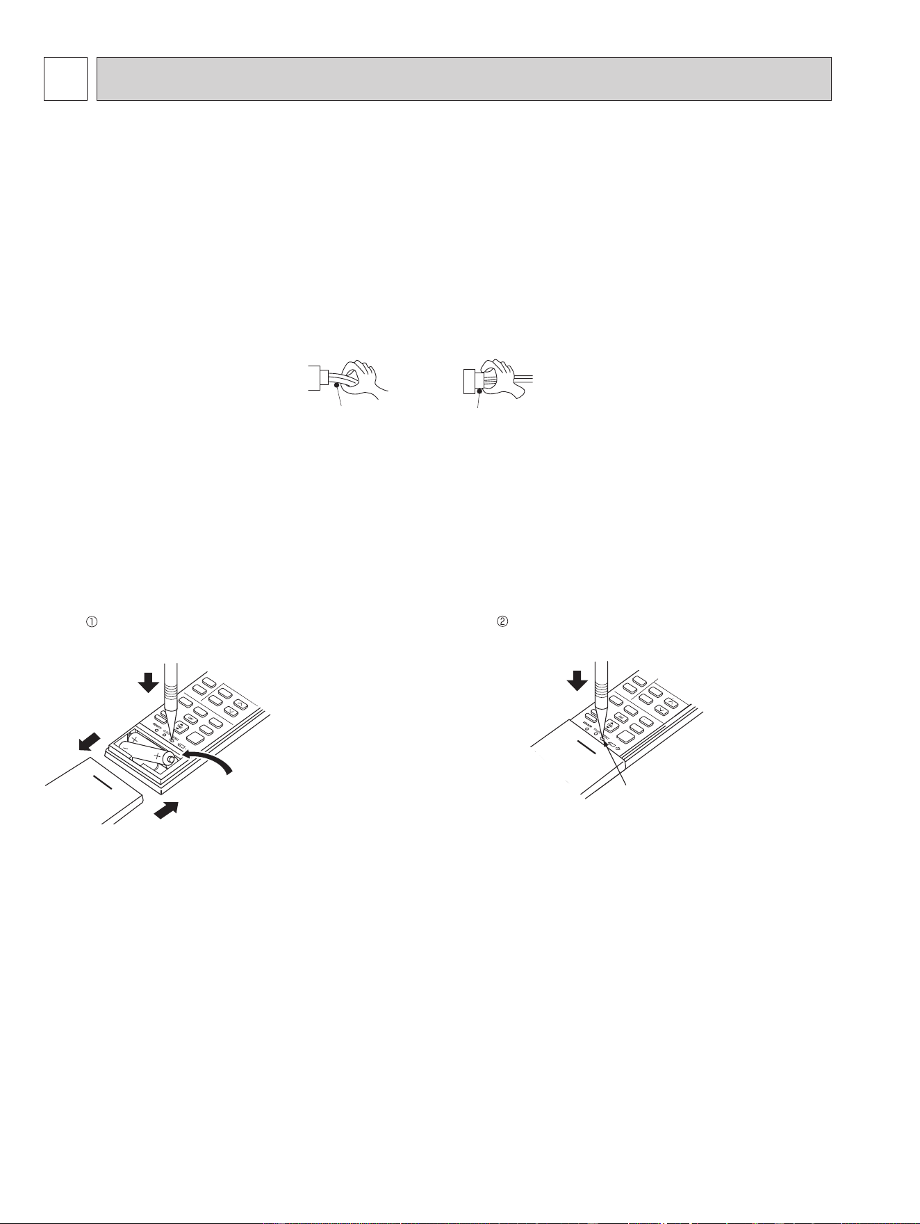
4. How to replace batteries
Weak batteries may cause the remote controller malfunction.
In this case, replace the batteries to operate the remote controller normally.
Lead wiring
Connector housing
<Incorrect>
<Correct>
NOTE: 1. If RESET button is not pressed, the remote controller may not operate correctly.
2. This remote controller has a circuit to automatically reset the microcomputer when batteries are replaced.
This function is equipped to prevent the microcomputer from malfunctioning due to the voltage drop caused by the
battery replacement.
3. Do not use the leaking batteries.
Press RESET button with a thin instrument, and
then use the remote controller.
Remove the front lid and insert batteries.
Then reattach the front lid.
Insert the negative pole of the
batteries first. Check if the polarity
of the batteries is correct.
RESET button
MSZ-FS06NA MSZ-FS09NA MSZ-FS12NA MSZ-FS15NA MSZ-FS18NA
OBH872
21
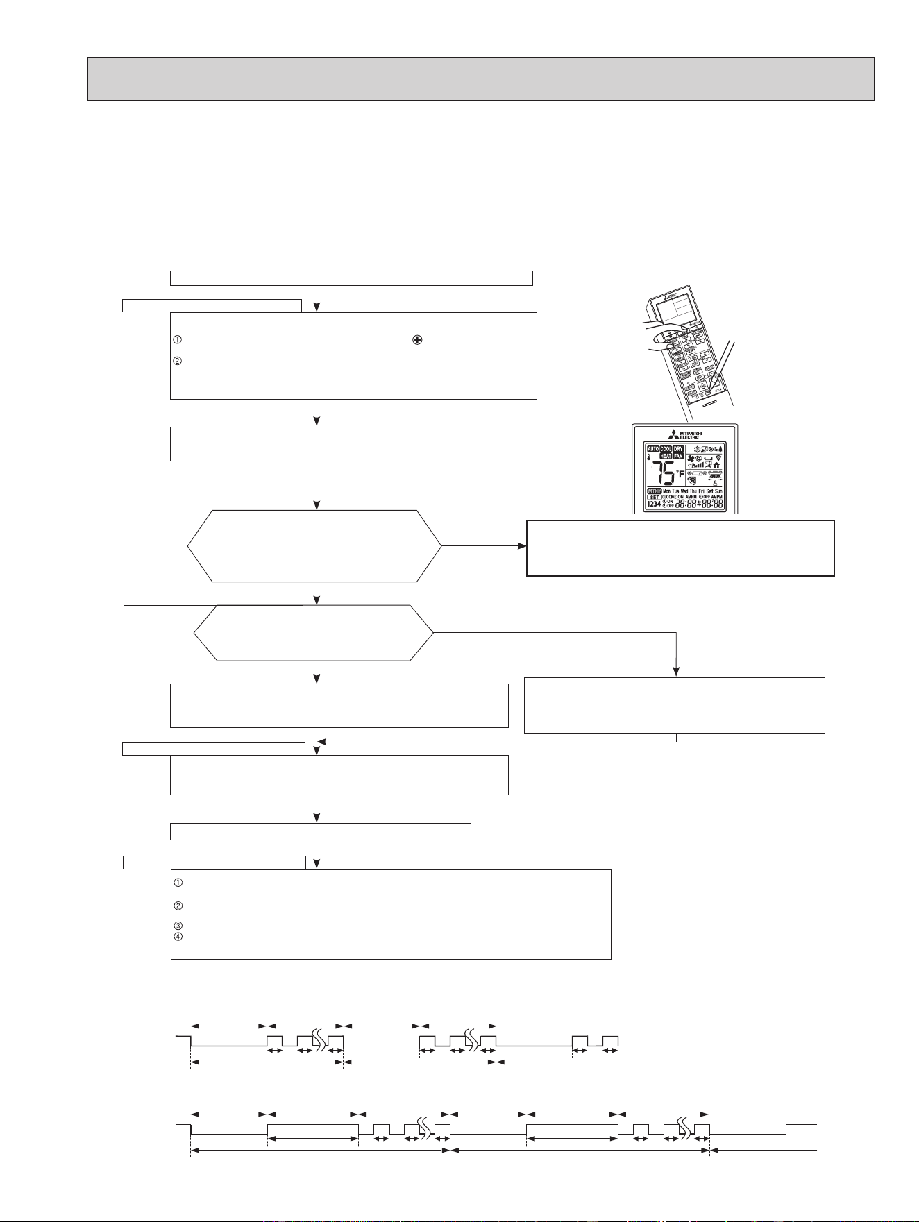
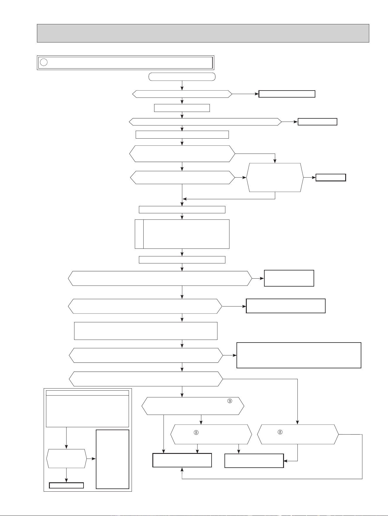
9-2. FAILURE MODE RECALL FUNCTION
Outline of the function
This air conditioner can memorize the abnormal condition which has occurred once.
Even though LED indication listed on the troubleshooting check table (9-4.) disappears, the memorized failure details can
be recalled.
1. Flow chart of failure mode recall function for the indoor/outdoor unit
Does the left lamp of the OPERATION INDICA-
TOR lamp on the indoor unit blink at the interval of
0.5 seconds?
Blinks: Either indoor or outdoor unit is abnormal.
Beep is emitted at the same timing as the
blinking of the left lamp of OPERATION
INDICATOR lamp.
*
2
Indoor unit is normal.
But the outdoor unit might be abnormal because there are some abnor-
malities that cannot be recalled with this way.
Check if outdoor unit is abnormal according to the detailed outdoor unit
failure mode recall function.
No
Yes
Judgment of indoor/outdoor abnormality
Before blinking, does the left lamp of
OPERATION INDICATOR lamp stay ON for 3
seconds?
When it stays ON for 3 seconds (without beep):
The outdoor unit is abnormal.
The indoor unit is abnormal.
Check the blinking pattern, and identify the abnormal point by referring to the
indoor unit failure mode table. (Refer to 9-2.2)
Make sure to check at least 2 consecutive blinking cycles.
*
2
Releasing the failure mode recall function
Release the failure mode recall function by the following procedures.
Turn OFF the power supply and turn it ON again.
Press RESET button of the remote controller.
The outdoor unit is abnormal.
Check the blinking pattern, and identify the abnormal point by referring
to the outdoor unit failure mode table. (Refer to outdoor unit service
manual.)
Make sure to check at least 2 consecutive blinking cycles. *3
Repair the failure parts.
Deleting the memorized abnormal condition
After repairing the unit, recall the failure mode again according to "Setting up the failure mode recall
function" mentioned above.
Press OFF/ON (stop/operate) button of the remote controller (the set temperature is displayed) with the
remote controller headed towards the indoor unit.
Press the emergency operation switch so that the memorized abnormal condition is deleted.
Release the failure mode recall function according to "Releasing the failure mode recall function" men-
tioned above.
Yes
(Blinks)
No
(OFF)
NOTE: 1. Make sure to release the failure mode recall function after it is set up, otherwise the unit cannot operate properly.
2. If the abnormal condition is not deleted from the memory, the last abnormal condition is kept memorized.
*2. Blinking pattern when the indoor unit is abnormal:
*3.Blinking pattern when the outdoor unit is abnormal:
ON
OFF
Beeps
Repeated cycle Repeated cycle
ON
OFF
No beep Beeps
Repeated cycle
2.5-second OFF
Blinking at 0.5-
second interval
2.5-second OFF 3-second ON
Blinking at 0.5-
second interval
Beeps
Repeated cycle
2.5-second OFF
Blinking at 0.5-
second interval
No beep Beeps
Repeated cycle
2.5-second OFF 3-second ON
Blinking at 0.5-
second interval
Repeated cycle
Beeps
The cause of abnormality cannot be found because the abnormality does not recur.
Setting up the failure mode recall function
Turn ON the power supply.
<Preparation of the remote controller>
While pressing both Operation select button and
TEMP
button
on the remote
controller at the same time, press RESET button.
First, release RESET button.
Hold down the other 2 buttons for another 3 seconds. Make sure that the indicators
on the LCD screen shown in the right gure are all displayed. Then release the but-
tons.
Press OFF/ON (stop/operate) button of the remote controller (the set temperature is
displayed) with the remote controller headed towards the indoor unit. *1
Operational procedure
*1 Regardless of normal or abnormal condition,
a short beep is emitted once the signal is
received.
NOTE: It takes up to 1 minute to indicate the outdoor unit abnormality.
Even if the OPERATION INDICATOR lamp is not lit, keep check-
ing at least 1 minute or longer.
OBH872
22
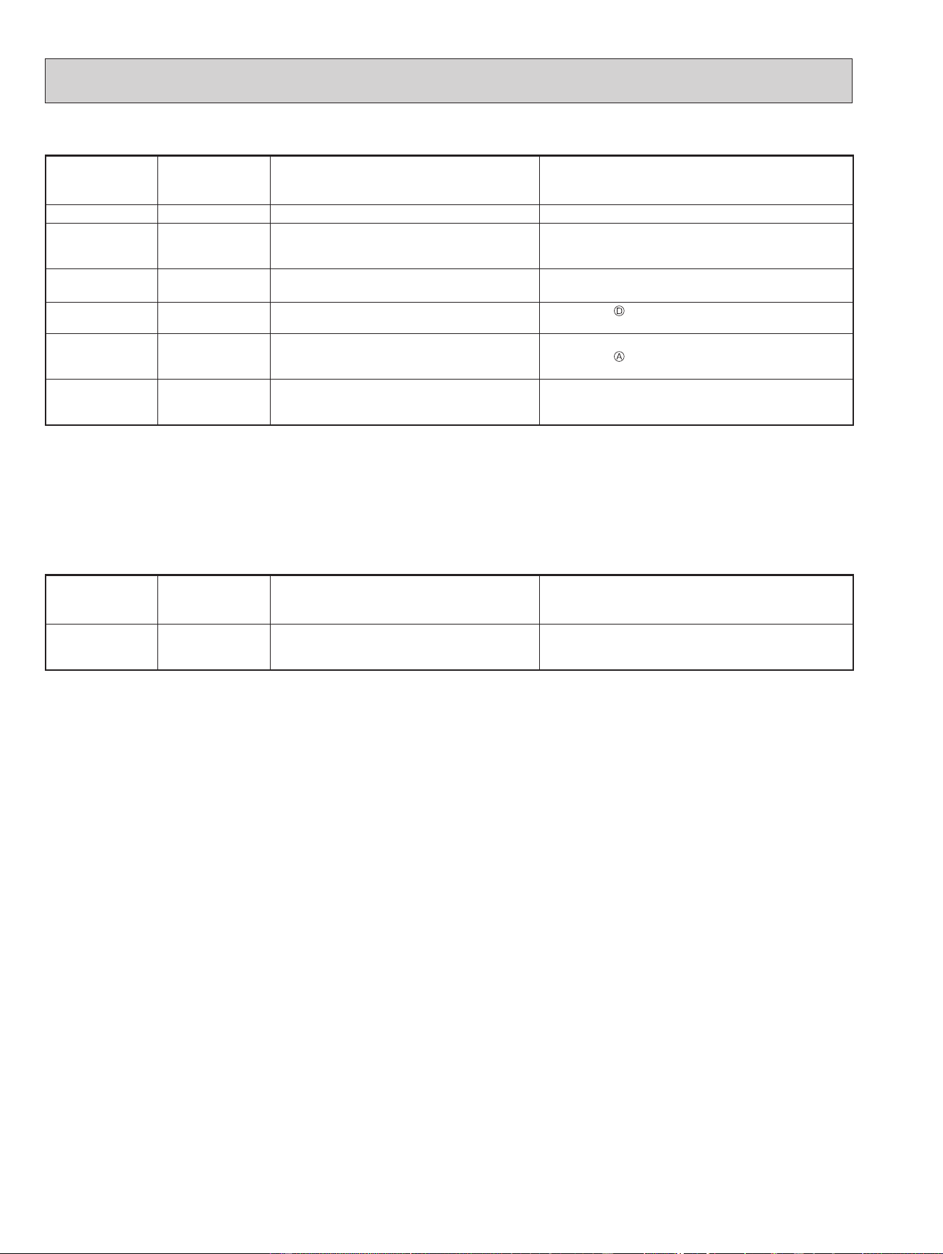
2. Indoor unit failure mode table
The left lamp of
the OPERATION
INDICATOR lamp
Abnormal point
(Failure mode)
Condition Remedy
Not lighted Normal — —
1-time blink every
0.5-second
Room temperature
thermistor
The room temperature thermistor short or
open circuit is detected every 8 seconds dur-
ing operation.
Refer to the characteristics of the room temperature
thermistor (9-7.).
2-time blink
2.5-second OFF
Indoor coil
thermistor
The indoor coil thermistor short or open circuit
is detected every 8 seconds during operation.
Refer to the characteristics of the main indoor coil ther-
mistor, the sub indoor coil thermistor (9-7.).
3-time blink
2.5-second OFF
Serial signal
The serial signal from outdoor unit is not re-
ceived for a maximum of 6 minutes.
Refer to 9-6.
"How to check miswiring and serial
signal error".
11-time blink
2.5-second OFF
Indoor fan motor
The rotational frequency feedback signal is
not emitted for 12 seconds after the indoor fan
motor is operated.
Refer to 9-6.
"Check of indoor fan motor".
12-time blink
2.5-second OFF
Indoor control
system
It cannot properly read data in the nonvolatile
memory of the indoor electronic control P.C.
board.
Replace the indoor electronic control P.C. board.
NOTE: Blinking patterns of this mode differ from the ones of TROUBLESHOOTING CHECK TABLE (9-4.).
3. Operation check on i-see sensor
While recalling the failure details, set the temperature to 66°F (19°C) to perform the simple check on the i-see sensor.
Place your hand over the i-see sensor, and the buzzer will beep at 1 second intervals. (Normal detection temperature range
is 93 to 102°F (34 to 39°C).)
If the buzzer does not beep, check for disconnection of the connectors.
Set the temperature to 73°F (23°C) to exit the simple check mode on the i-see sensor.
The left lamp of
the OPERATION
INDICATOR lamp
Abnormal point
(Failure mode)
Condition Remedy
6-time blink i-see sensor
Poor contact in i-see sensor wiring
Failure in loading corrected data of i-see
sensor
Check for disconnection of the connectors.
OBH872
23
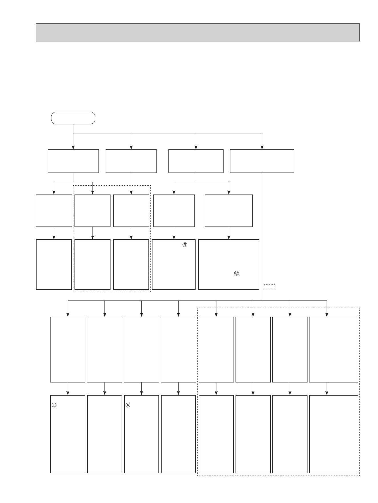
9-3. INSTRUCTION OF TROUBLESHOOTING
*1 "Test Run operation" means the
operation within 30 minutes after
the emergency operation switch
is pressed.
Indoor unit operates.
Outdoor unit does
not operate.
Indoor unit operates.
Outdoor unit does
not operate normally.
Indoor unit does not
receive the signal from
remote controller.
LEFT lamp of the OPERA-
TION INDICATOR lamp is
blinking ON and OFF.
Outdoor unit
operates only
in Test Run
operation. *1
Outdoor unit
does not
operate even
in Test Run
operation. *1
Unit does not
operate nor-
mal operation
in COOL or
HEAT mode.
Indoor unit
operates, when
the emergency
operation switch
is pressed.
Indoor unit does
not operate, when
the emergency
operation switch is
pressed.
Check room
temperature
thermistor.
Refer to 9-7.
"Test point
diagram and
voltage".
Refer to "How
to check
inverter/com-
pressor".
Refer to
"Check of
R.V. coil".
Refer to 9-6.
"Check of remote
controller and
indoor electronic
control P.C.
board".
1. Check indoor/outdoor
connecting wire.
(Check if the power is
supplied to the indoor
unit.)
2. Refer to 9-6. "Check
of indoor P.C. board
and indoor fan motor".
LEFT lamp
Blink on and
o at 0.5-sec-
ond intervals
Cause:
Indoor
/Outdoor unit
• Miswiring or
trouble of
serial signal
LEFT lamp
2-time blink
Cause:
Indoor unit
• Trouble
of room
temperature
/ indoor coil
thermistor
LEFT lamp
3-time blink
Cause:
Indoor unit
• Trouble of
indoor fan
motor
LEFT lamp
4-time blink
Cause:
Indoor unit
• Trouble
of indoor
unit control
system
LEFT lamp
5-time blink
Cause:
Outdoor unit
• Outdoor
power sys-
tem abnor-
mality
LEFT lamp
6-time blink
Cause:
Outdoor unit
• Trouble of
thermistor
in outdoor
unit
LEFT lamp
7-time blink
Cause:
Outdoor unit
• Trouble of
outdoor
control
system
LEFT lamp
14-time blink
or more
Cause:
Outdoor unit
• Other abnormality
Indoor/
Outdoor unit
• Trouble of ther-
mistors
Start
Refer to 9-6.
"How to
check
miswiring
and serial
signal error".
Check room
temperature
thermistor
and indoor
coil thermis-
tor. Refer to
9-7. "Test
point dia-
gram and
voltage".
Refer to 9-6.
"Check of
indoor fan
motor".
Replace the
indoor
electronic
control P.C.
board.
Refer to
"How to
check
inverter/
compressor".
Refer to
"Check of
outdoor
thermistors".
Replace the
inverter P.C.
board or the
outdoor
electronic
control P.C.
board.
• Check "Flow
chart of the
detailed outdoor
unit failure mode
recall function."
• Check thermis-
tors.
Refer to "Test
point diagram
and voltage"
in the service
manual of
indoor and
outdoor unit.
Refer to outdoor unit service manual.
1. Check of the unit.
*2 There is possibility that diesel explosion may occur due to the air
mixied in the refrigerant circuit.
First, ensure that there are no leakage points on the valves, are
connections, etc. that allow the air to ow into the refrigerant circuit,
or no blockage points (e.g. clogged or closed valves) in the refrigerant
circuit that cause an increase in pressure.
If there is no abnormal point like above and the system operates cool-
ing and heating modes normally, the indoor thermistor might have a
problem, resulting in false detection.
Check both the indoor coil thermistor and the room temperature ther-
mistor, and replace faulty thermistor(s), if any.
(Do not start the operation again without repair to prevent hazards.)
If blinking of OPERATION
INDICATOR lamp cannot be
checked, it can be checked with
failure mode recall function.
*2
OBH872
24
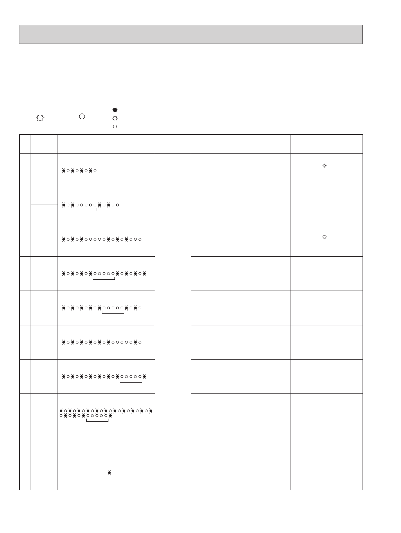
9-4. TROUBLESHOOTING CHECK TABLE
Before taking measures, make sure that the symptom reappears for accurate troubleshooting.
When the indoor unit has started operation and detected an abnormality of the following condition (the first detection after the
power ON), the indoor fan motor turns OFF and OPERATION INDICATOR lamp blinks.
• The following indicator applies regardless of shape of the indication.
OPERATION INDICATOR
Lighted
Blinking
Not lighted
No.
Abnormal
point
Operation indicator lamp Symptom Condition Remedy
1
Miswiring
or serial
signal
LEFT lamp blinks.
0.5-second ON
0.5-second OFF
Indoor unit and
outdoor unit do
not operate.
The serial signal from the outdoor unit is not
received for 6 minutes.
•
Refer to 9-6.
"How to check
miswiring and serial signal er-
ror".
2
Indoor coil
thermistor
LEFT lamp blinks.
2-time blink
2.5-second OFF
The indoor coil or the room temperature ther-
mistor is short or open circuit.
•
Refer to the characteristics of
indoor coil thermistor, and the
room temperature thermistor
(9-7.).
Room tem-
perature
thermistor
3
Indoor fan
motor
LEFT lamp blinks.
3-time blink
2.5-second OFF
The rotational frequency feedback signal is
not emitted during the indoor fan operation.
•
Refer to 9-6.
"Check of in-
door fan motor".
4
Indoor con-
trol system
LEFT lamp blinks.
4-time blink
2.5-second OFF
It cannot properly read data in the nonvolatile
memory of the indoor electronic control P.C.
board.
•
Replace the indoor electronic
control P.C. board.
5
Outdoor
power sys-
tem
LEFT lamp blinks.
5-time blink
2.5-second OFF
It consecutively occurs 3 times that the com-
pressor stops for overcurrent protection or
start-up failure protection within 1 minute after
start-up.
•
Refer to "How to check of in-
verter/compressor".
Refer to outdoor unit service
manual
•
Check the stop valve.
6
Outdoor
thermistors
LEFT lamp blinks.
6-time blink
2.5-second OFF
The outdoor thermistors short or open circuit
during the compressor operation.
•
Refer to "Check of outdoor
thermistor".
Refer to outdoor unit service
manual.
7
Outdoor
control sys-
tem
LEFT lamp blinks.
7-time blink
2.5-second OFF
It cannot properly read data in the nonvolatile
memory of the inverter P.C. board or the out-
door electronic control P.C. board.
•
Replace the inverter P.C. board
or the outdoor electronic control
P.C. board.
Refer to outdoor unit service
manual.
8
Other ab-
normality
LEFT lamp blinks.
14-time blink or more
2.5-second OFF
An abnormality other than the above is de-
tected.
An abnormality of the indoor thermistors, the
defrost thermistor or ambient temperature
thermistor is detected.
•
Check the stop valve.
•
Check the 4-way valve.
•
Check the abnormality in detail
using the failure mode recall
function for outdoor unit.
•
Refer to TEST POINT DIA-
GRAM AND VOLTAGE" on the
service manual of indoor and
outdoor unit for the characteris-
tics of the thermistors. (Do not
start the operation again with-
out repair to prevent hazards.)
9
Outdoor
control sys-
tem
LEFT lamp lights up.
Outdoor unit
does not oper-
ate
It cannot properly read data in the nonvolatile
memory of the inverter P.C. board or the out-
door electronic control P.C. board.
•
Check the blinking pattern of
the LED on the inverter P.C.
board or the outdoor electronic
control P.C. board.
OBH872
25
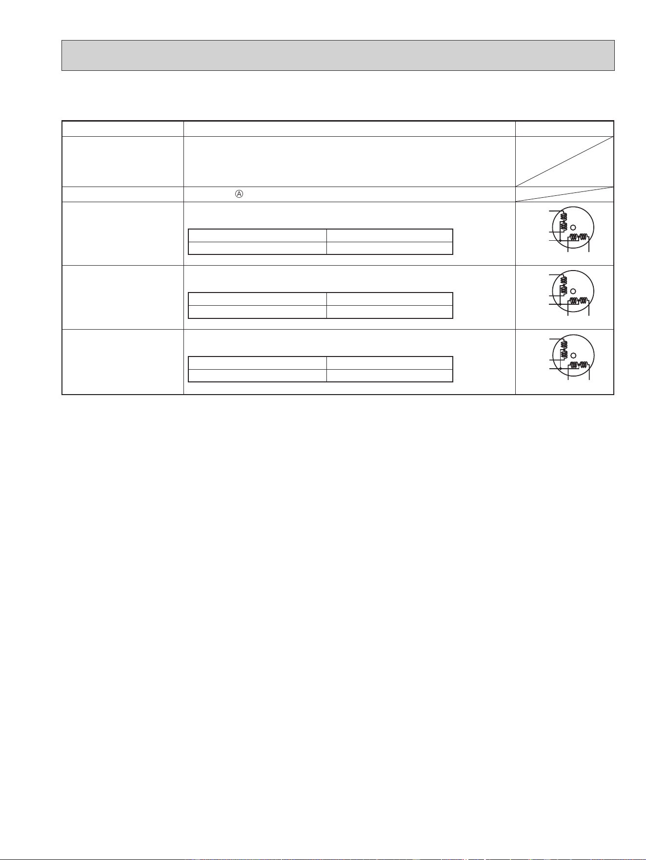
9-5. TROUBLE CRITERION OF MAIN PARTS
MSZ-FS06NA MSZ-FS09NA MSZ-FS12NA MSZ-FS15NA MSZ-FS18NA
Part name Check method and criterion Figure
Room temperature
thermistor (RT11)
Indoor coil thermistor
(RT12, RT13)
Measure the resistance with a tester.
Refer to 9-7. "Test point diagram and voltage", "Indoor electronic control
P.C. board", for the chart of thermistor.
Indoor fan motor (MF)
Check 9-6.
"Check of indoor fan motor".
Vane motor (MV1)
(HORIZONTAL)
Measure the resistance between the terminals with a tester.
(Temperature: 50 - 86°F (10 - 30°C))
Color of the lead wire Normal
RED - SKY* 262 - 328 Ω
SKY
SKY
RED
SKY
SKY
ROTOR
Vane motor (MV2)
(VERTICAL)
Measure the resistance between the terminals with a tester.
(Temperature: 50 - 86°F (10 - 30°C))
Color of the lead wire Normal
RED - SKY* 219 - 273 Ω
SKY
SKY
RED
SKY
SKY
ROTOR
i-see SENSOR MOTOR
(MT)
Measure the resistance between the terminals with a tester.
(Temperature: 50 - 86°F (10 - 30°C))
Color of the lead wire Normal
RED - BLK 262 - 328 Ω
BLK
BLK
RED
BLK
BLK
ROTOR
*SKY=SKY BLUE
OBH872
26
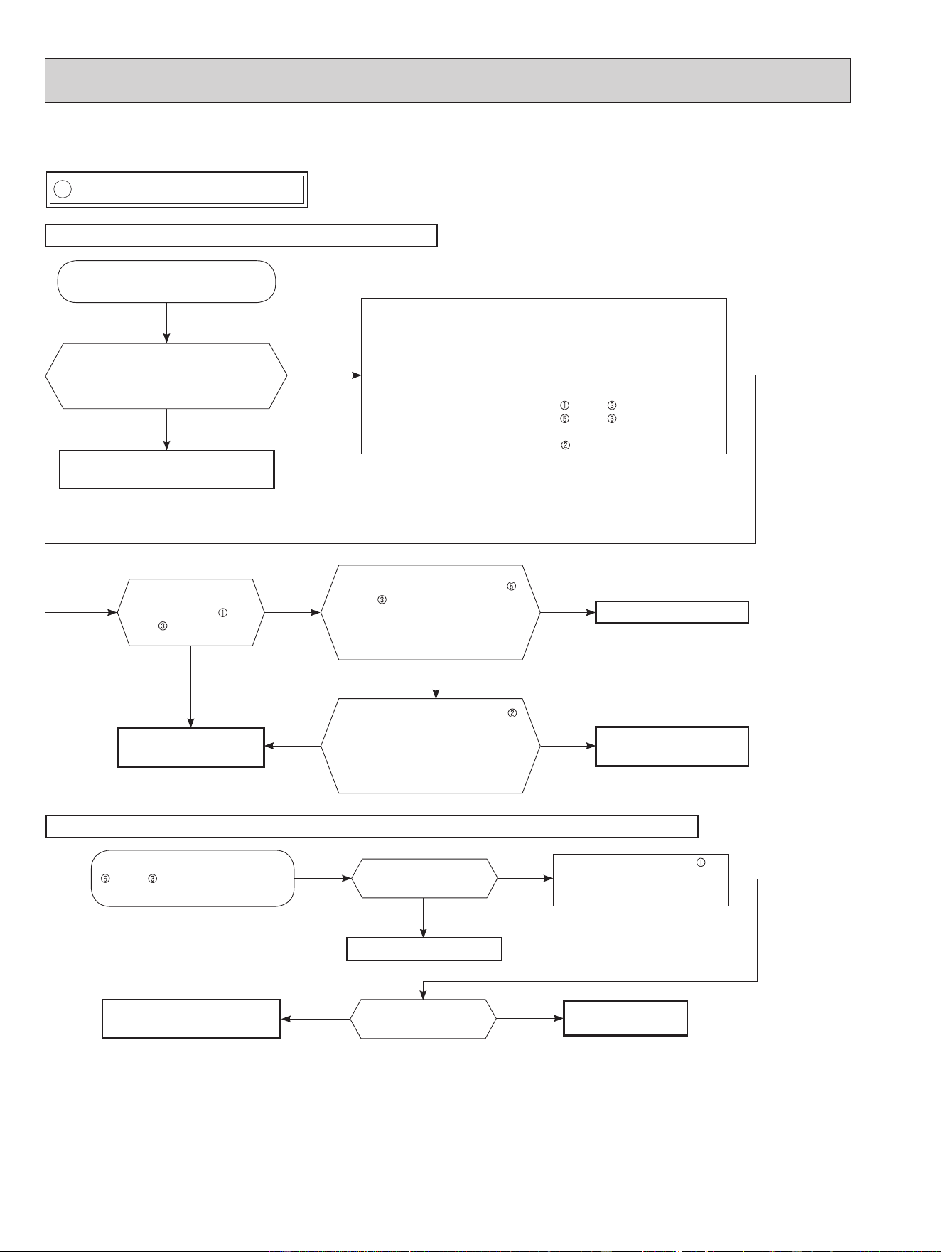
A Check of indoor fan motor
9-6. TROUBLESHOOTING FLOW
The indoor fan motor error has occurred, and the indoor fan does not operate.
Turn OFF the power supply.
Is there any foreign matter that interferes
the rotation of the line ow fan?
Yes
No
Remove the foreign matter and
adjust the line ow fan.
Pay enough attention to the high voltage on the fan motor connector CN211.
Turn ON the power supply, wait 5 seconds or more, and then press
the emergency operation switch.
Measure the supply voltage as follows within 12 seconds after the emer-
gency operation switch is pressed.
If more than 12 seconds passes, turn OFF the power supply and turn it
ON again, then measure the voltage.
*
1
<Indoor power P.C. board>
1. Measure the voltage between CN211
(+) and (–).
2. Measure the voltage between CN211
(+) and (–).
<Indoor electronic control P.C. board>
3. Measure the voltage between CN102 (+) and JPG (GND)(–).
*
1
.
If more than 12 seconds passes after the emergency operation switch
is pressed, the voltage measured at 2. above goes 0 VDC although the
indoor P.C. board is normal.
Does the voltage between CN211
(+) and (–) on the power P.C. board
rise to the range of 3 to 6 VDC within
12 seconds after the emergency
operation switch is pressed?
Replace the indoor fan motor.
Yes
No
The indoor fan motor error has occurred, and the indoor fan repeats "12-second ON and 30-second OFF" 3 times, and then stops.
Measure the voltage between CN211
(+) and (–) while the fan motor is
rotating.
Replace the indoor power
P.C. board.
Is it unchanged holding 0
or 15 VDC?
No
(Changed)
Yes
(Unchanged)
Measure the voltage CN102 (+)
and JPG (GND)(–) on the indoor
electronic control P.C board when
the fan motor is rotating.
Replace the indoor fan motor.
Is there 294/325 VDC
between CN211 (+)
and (–) ?
Yes
Does the voltage between CN102
(+) and JPG (GND)(–) on the indoor
electronic control P.C. board fall to
2 V or less within 12 seconds after
the emergency operation switch is
pressed?
Replace the indoor electronic
control P.C. board.
No
Yes
Replace the indoor power P.C.
board.
Is it unchanged holding 0
or 5 VDC?
No
(Changed)
Yes
(Unchanged)
Replace the indoor
electronic control P.C.
board.
No
OBH872
27
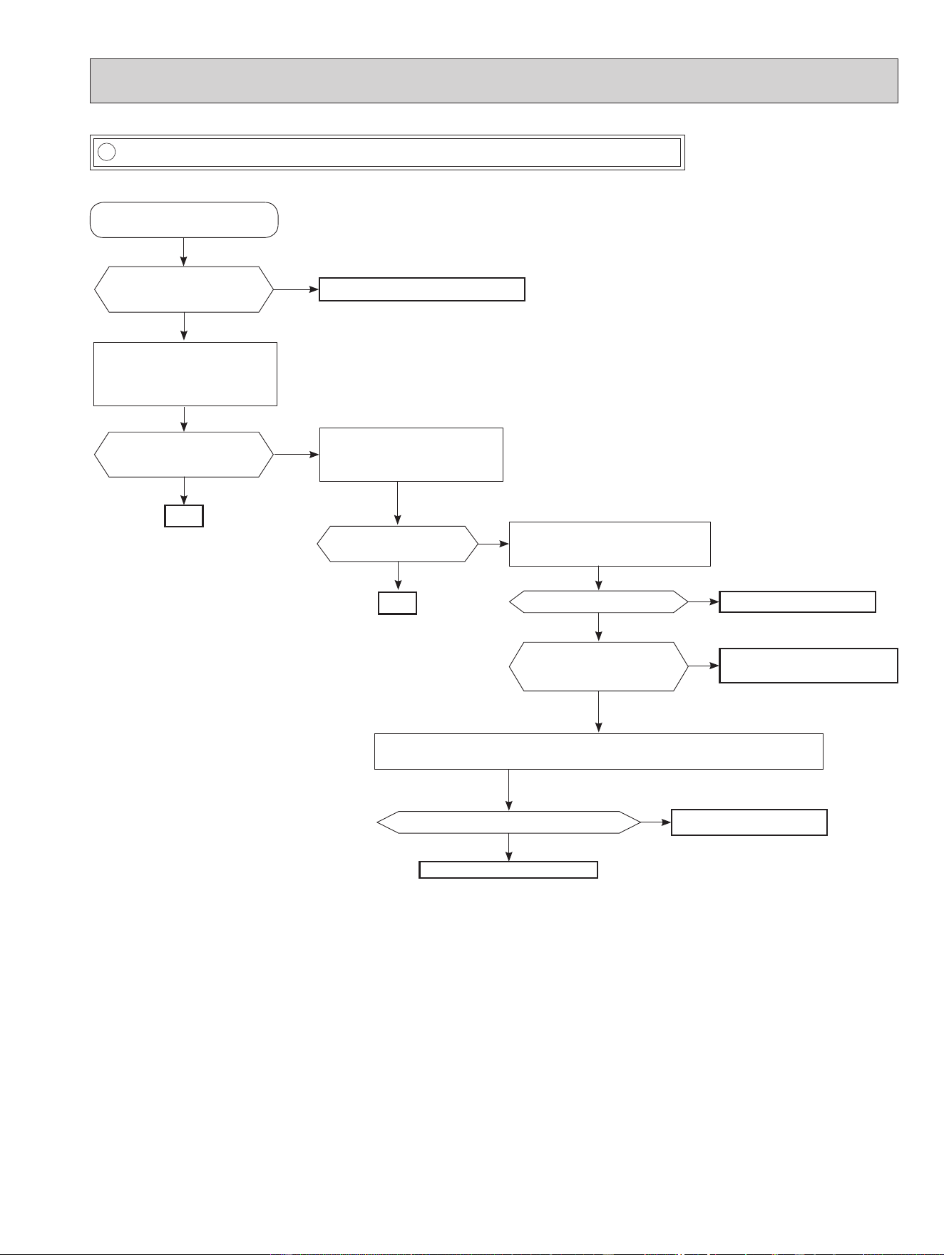
B Check of remote controller and indoor electronic control P.C. board
Check if the remote controller is exclusive for this air conditioner.
Does the unit operate with the
remote controller?
OK
Yes
No
(Not clear)
Replace the batteries. (Refer to 9-1.4.)
Press OFF/ON (stop/operate)
button on the remote controller.
Is LCD display on the remote
controller visible?
Remove the batteries, then set them
back and press RESET button.
(Refer to 9-1.4.)
Check if the unit operates with the
remote controller.
Yes
No
Turn ON a radio to AM and press OFF/
ON (stop/operate) button on the remote
controller. *1
Is noise heard from radio?
Yes
No
Replace the remote controller.
Are there any uorescent lights
of inverter or rapid-start type
within the range of 3.28 ft.? *2
Yes
No
• Reinstall the unit away from lights.
• Attach a lter on receiving part.
Replace the receiver P.C. board.
Assign a number of remote controller.
(Refer to 7-2.)
Check if the unit operates with the
remote controller.
Does the unit operate with
the remote controller ?
Yes
No
OK
Measure the voltage between receiver P.C. board connector CN301 No.1(-) and No.3(+)
when the remote controller button is pressed.
Is the voltage approximately 4 VDC - 5 VDC?
No
Yes
Replace the indoor electronic
control P.C. board.
*
1 Look at the image of the signal transmitting section of
the remote controller through the monitor of a digital
camera or a camera phone. It is normal if the LED
of the signal transmitting section lights up when the
OFF/ON (stop/operate) button on the remote control-
ler is pressed. However, it may be dicult to see the
illuminated LED of the signal transmitting section with a
smartphone camera.
*
2 If the inverter uorescent light is turned on when the
room is cool, the unit may have diculty receiving the
signal from the remote controller or may not be able to
operate with it; if the inverter uorescent light is turned
on when the room is warm, the unit may be able to
operate with the remote controller.
OBH872
28
C Check of indoor P.C. board and indoor fan motor
Turn OFF the power supply.
Remove indoor fan motor connector CN211
from indoor power P.C. board and vane
motor connector CN151 from the indoor
electronic control P.C. board and turn ON
the power supply.
Does the unit operate with the remote
controller?
Does OPERATION INDICATOR lamp light
up by pressing the emergency operation
switch?
Yes
No
Measure the resistance of indoor fan
motor.
Refer to 9-5.
Short circuit:
Replace the indoor fan motor.
Turn OFF the power supply.
Check both “parts side” and “pattern
side” of the indoor power P.C. board
visually.
Replace the varistor (NR11)
and fuse (F11). 3
Are the varistor (NR11)
burnt and the fuse (F11)
blown?
No
No
Yes
Yes
Be sure to check both the fuse
and the varistor in any case.
Is the fuse (F11) blown
only?
Measure the resistance between
CN211
(+) and (-) of indoor fan
motor connector.
*
1,
*
2
Yes
Is the resistance 1MΩ or more?
Replace the fuse (F11) and the
indoor fan motor.
*
3
No
Replace the fuse (F11).
*
3
Measure the resistance of
resistor (R111) on the indoor
power P.C. board.
No
No
Replace the indoor
power P.C. board and
the indoor fan motor.
Replace the indoor electronic control P.C. board.
Measure the resistance of the vane
motor coil.
Refer to 9-5.
Short circuit:
Replace the vane motor and the indoor
electronic control P.C. board.
*
1. The fan motor connector's lead wire is red,
whereas
is black.
*
2. Connect "+" of the tester to fan motor connector's
lead wire, and “-” to lead wire, otherwise the
resistance cannot be measured properly.
*
3. Please replace the fuse after removing the indoor
power P.C. board from the electrical box.
Is there approximately 5 VDC between
5 V (+) and JPG (GND) (-) of the
indoor electronic control P.C. board?
Is there approximately 12 VDC
between 12 V (+) and JPG (GND) (-)
of the indoor electronic control P.C.
board?
Is connector CN102 on the
indoor electronic control P.C.
board or lead wires discon-
nected?
Yes
Replace the indoor fan motor.
Yes
Connect the connector or repair discon-
nection.
No
Yes
Varistor
(NR11)
Indoor electronic
control P.C. board
GND(JPG)
Fuse (F11)
R111
CN211
Indoor power
P.C. board
CN102
Is the resistance of
resistor (R111) approximately
3.9 Ω ?
Measure the resistance of the i-see
SENSOR MOTOR coil. Refer 9-5.
Short circuit:
Replace the i-see SENSOR MOTOR and
the indoor electronic P.C. board.
OBH872
29
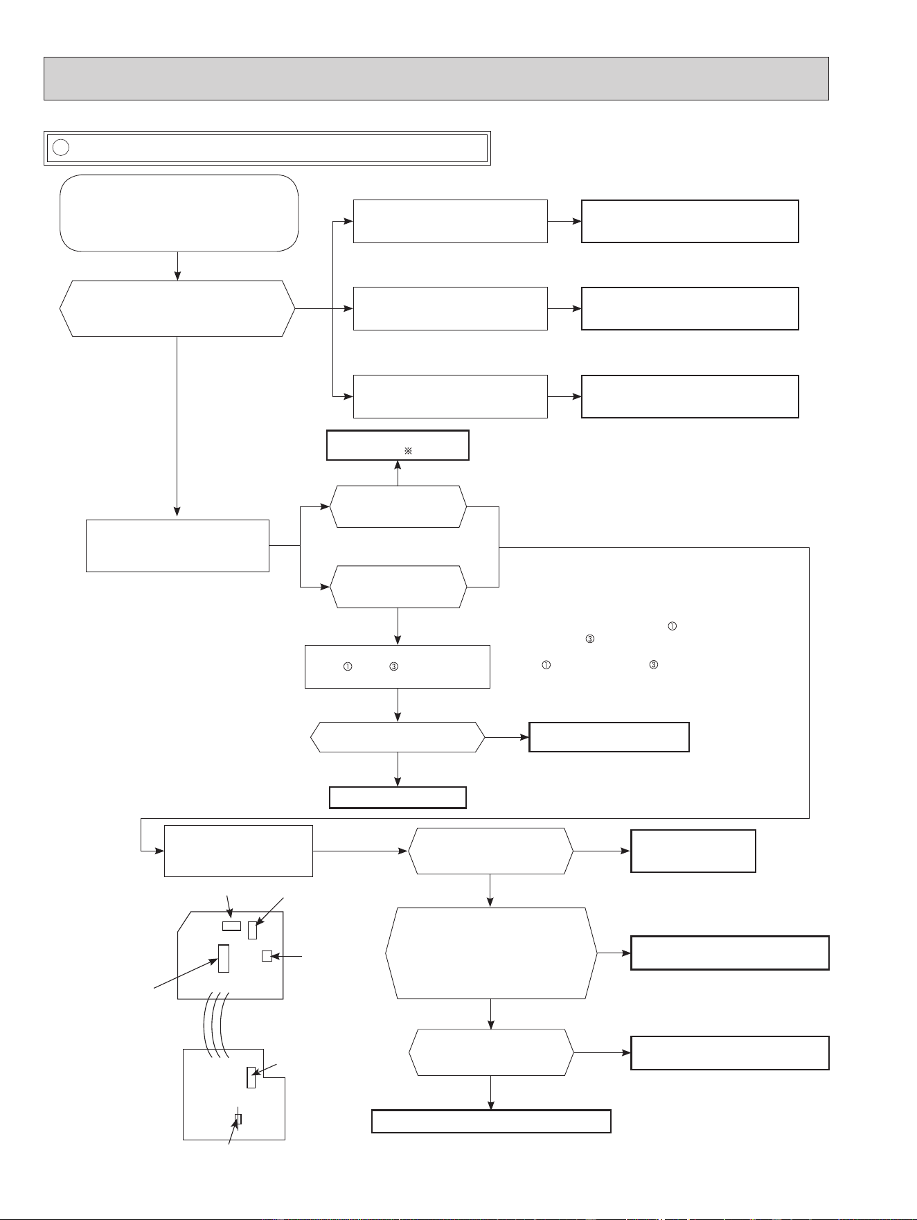
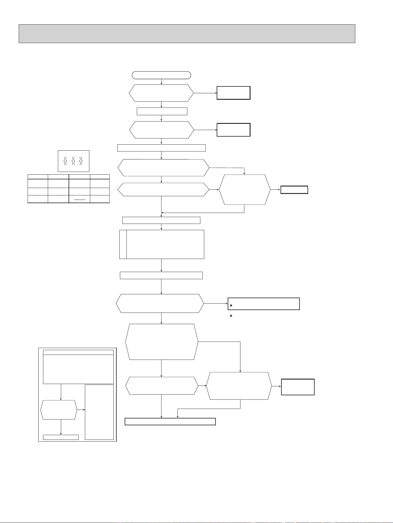
D How to check miswiring and serial signal error
• Turn OFF inverter-controlled lighting
equipment.
• Turn OFF the power supply and then
turn ON again.
• Press the emergency operation switch.
A
Is serial signal
error indicated 6
minutes later?
B
Yes
• Reinstall
either the unit
or the light
away from
each other.
• Attach a lter
on remote
control receiv-
ing section
of the indoor
unit.
No
Turn OFF the power supply.
Is there rated voltage in the power supply?
Yes
Yes
Yes
Yes
No
Turn ON the power supply.
Check the power supply.
Is there rated voltage between the outdoor terminal block S1 and S2?
No
Check the wiring.
Press the emergency operation switch once.
Does the left lamp of OPERATION INDICATOR
lamp light up? <Conrmation of the power to
the indoor unit>
No
Is serial signal error indicated 6 minutes later?
No
Is there any miswiring,
poor contact, or wire
disconnection of the
indoor/outdoor connect-
ing wire?
Yes
Correct them.
No
A
Turn OFF the power supply.
Check once more if the indoor/outdoor
connecting wire is not miswiring.
Bridge the outdoor terminal block S2 and
S3. *1
B
*
1. Miswiring may damage indoor electronic control P.C.
board during the operation.
Be sure to conrm the wiring is correct before the opera-
tion starts.
Turn ON the power supply.
Does the LED on the inverter P.C. board repeat
"3.6-second-OFF and 0.8-second-ON quick blinking"?
*
3
Yes
No
(Lighted
or not
lighted)
Replace the inverter P.C. board.
*
2
*
2. Be careful of the residual voltage of
smoothing capacitor.
Is there amplitude of 10 to 20 VDC between the indoor terminal block
S2 and S3? <Conrmation of serial signal>
Yes
Check the wiring
If there are any errors of the indoor/outdoor connecting wire:
such as the damage of the wire, intermediate connection,
and/or poor contact to the terminal block, replace the indoor/
outdoor connecting wire.
No
Is there 2 VDC or less between CN202 (+)
and JPG (GND)(-) on the indoor electronic
control P.C. board?
No
Yes
*
3. Be sure to check this within 3 minutes after turning ON.
After 3 minutes, LED blinks 6 times. Even when the
inverter P.C. board is normal, LED blinks 6 times after 3
minutes.
Is there 2 VDC or less between
CN202 (+) and JPG (GND)(-) on
the indoor electronic control P.C.
board?
Is there 2 VDC or less between
CN202A (+) and JPG (GND)(-)
on the indoor electronic control P.C.
board?
Replace the indoor elec-
tronic control P.C. board.
No Yes No
Yes
Is the bus-bar voltage of the inverter P.C. board normal?
(Refer to "TEST POINT DIAGRAM AND VOLTAGE" in the outdoor service manual.)
No
Yes
Check of power supply.
(Refer to the outdoor
service manual.)
Turn OFF the power supply.
Remove the bridge between the outdoor terminal block S2 and S3.
Turn ON the power supply.
Yes
No
Replace the indoor power
P.C. board.
Is there rated voltage between the indoor terminal block S1 and S2?
<Conrmation of power voltage>
MUZ type
OBH872
30
MXZ Type
Is there rated voltage in
the power supply?
Is there any miswiring,
poor contact, or wire
disconnection of the
indoor/outdoor
connecting wire?
*1 Miswiring may damage indoor electronic control
P.C. board during the operation.
Be sure to confirm the wiring is correct before the
operation starts.
(Lit
or not lit)
No
Yes
No
Yes
Yes
No
Yes
No
Be sure to release the failure-mode
recall function after checking.
No
No
Yes
No
Yes
Yes
Yes
No
Yes
Turn OFF the power supply.
Turn ON the power supply.
Is there rated voltage between
outdoor terminal block S1 and
S2?
Does the left lamp of OPERATION
INDICATOR lamp light up?
<Confirmation of the power to the indoor unit>
Press EMERGENCY OPERATION switch once.
Check the power
supply.
A
Turn OFF the power supply.
Check once more if the indoor/outdoor
connecting wire is not miswiring.
Bridge the outdoor terminal block S2 and
S3. *1
B
Turn ON the power supply.
Check the wiring.
Correct them.
Turn OFF the power supply.
Remove the bridge between
outdoor terminal block S2 and S3.
Turn ON the power supply.
Is there amplitude of 10 to 20 V DC
between outdoor terminal block S2
and S3? <Confirmation of serial
signal>
Is there rated voltage between
indoor terminal block S1 and S2?
<Confirmation of power voltage>
Replace the indoor electronic control P.C. board.
2 Be careful of the residual
voltage of smoothing capacitor.
Replace the outdoor control P.C. board.
2
Is there any error of the
indoor/outdoor connecting wire,
such as the damage of the wire,
intermediate connection, poor
contact to the terminal block?
Replace the
indoor/outdoor
connecting wire.
Is serial signal
error indicated
6 minutes later?
Yes
No
· Turn OFF inverter-controlled lighting
equipment.
· Turn OFF the power supply and
then turn ON again.
· Press EMERGENCY OPERATION
switch.
B
· Reinstall
either the
unit or the
light away
from each
other.
· Attach a filter
on remote
control
receiving
section of
the indoor
unit.
A
Is serial signal error indicated 6 minutes later?
No
Does the LED on the outdoor control P.C.
board repeat "3.6-second-OFF
and 0.8-second-ON quick blinking"?
LED indication
for communication status
Communication status is indicated
by the LED.
Blinking: normal communication
Lit: abnormal communication or
not connected
Pattern 1 and 2 is repeatedly displayed
alternately. Each pattern is displayed for
15 seconds.
NOTE: "Lit" in the table below does not
indicate abnormal communication.
Unit status
Outdoor control P.C. board
Blinking
LED1 LED2
LED3
LED 1 LED 3LED 2
Pattern
1
2
3
Unit B
status
Unit C
status
Unit A
status
Unit D
status
Unit E
status
Not lit
Lit
Blinking
OBH872
31
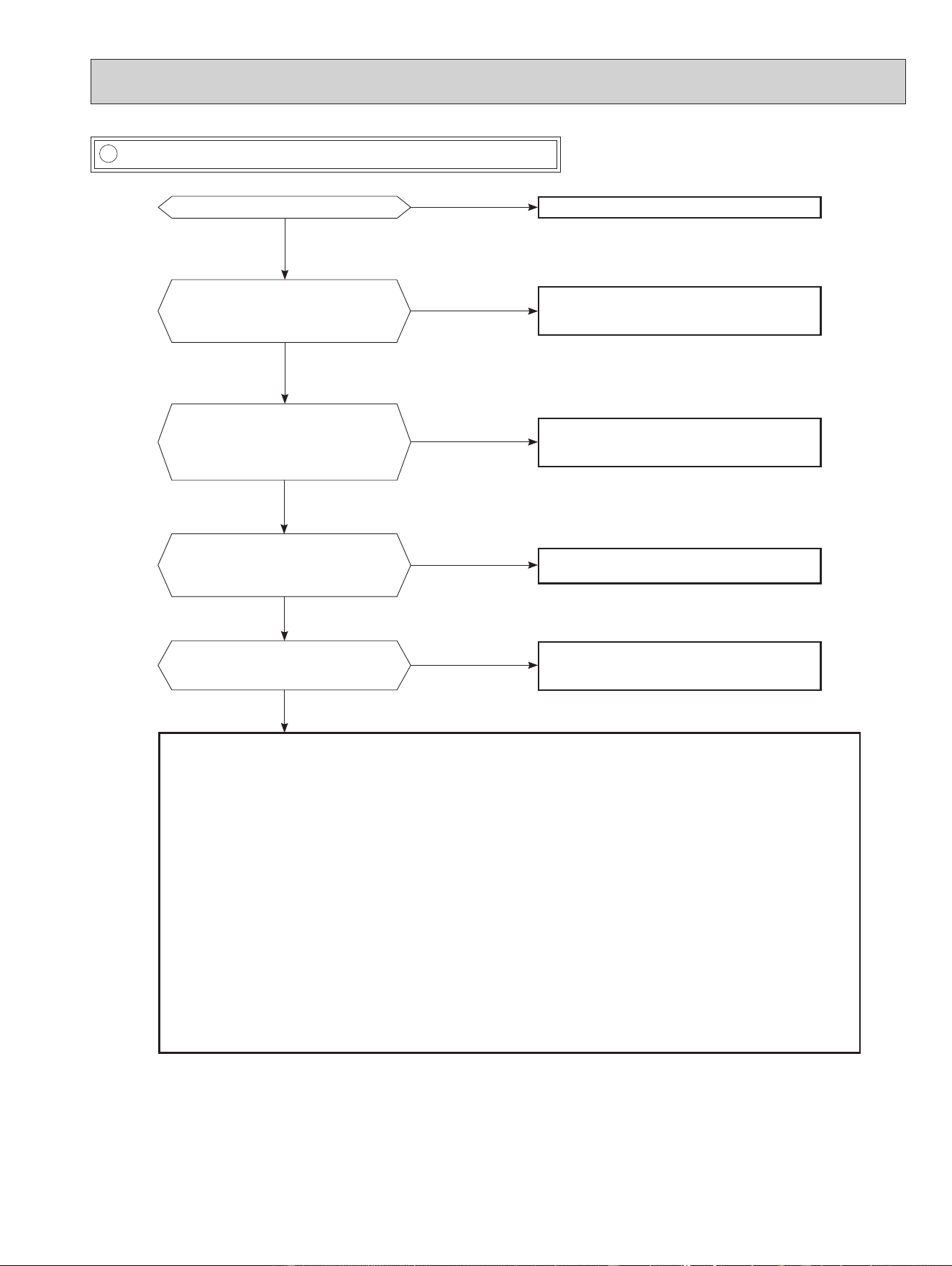
E Electromagnetic noise enters into TV sets or radios
Is the unit grounded?
No
No
No
No
No
Ground the unit.
Yes
Yes
Yes
Yes
Yes
Is the distance between the antennas
and the indoor unit within 9.91 ft. (3m),
or is the distance between the antennas
and the outdoor unit within 9.91 ft. (3m)?
Extend the distance between the antennas and
the indoor unit, and/or the antennas and the
outdoor unit.
Is the distance between the TV sets or ra-
dios and the indoor unit within 3.28 ft.
(1m)
,
or is the distance between the TV sets or
radios and the outdoor unit within
9.91 ft.
(3m)
?
Extend the distance between the TV sets and/
or radios and the indoor unit, or the TV sets or
radios and the outdoor unit.
Are the antennas damaged?
Is the coaxial cable damaged?
Is there any poor contact in the anten-
na wiring?
Replace or repair the antenna.
Replace or repair the coaxial cable.
Is the indoor/outdoor connecting wire
of the air conditioner and the wiring of
the antennas close?
Extend the distance between the indoor/outdoor
connecting wire of the air conditioner and the wir-
ing of the antennas.
Even if all of the above conditions are fullled, the electromagnetic noise may enter, depending on the electric eld strength
or the installation condition (combination of specic conditions such as antennas or wiring).
Check the following before asking for service.
1. Devices aected by the electromagnetic noise
TV sets, radios (FM/AM broadcast, shortwave)
2. Channel, frequency, broadcast station aected by the electromagnetic noise
3. Channel, frequency, broadcast station unaected by the electromagnetic noise
4. Layout of:
indoor/outdoor unit of the air conditioner, indoor/outdoor wiring, ground wire, antennas, wiring from antennas, receiver
5. Electric eld intensity of the broadcast station aected by the electromagnetic noise
6. Presence or absence of amplier such as booster
7. Operation condition of air conditioner when the electromagnetic noise enters in
1) Turn OFF the power supply once, and then turn ON the power supply. In this situation, check for the electromagnetic
noise.
2) Within 3 minutes after turning ON the power supply, press OFF/ON (stop/operate) button on the remote controller for
power ON, and check for the electromagnetic noise.
3) After a short time (3 minutes later after turning ON), the outdoor unit starts running. During operation, check for the
electromagnetic noise.
4) Press OFF/ON (stop/operate) button on the remote controller for power OFF, when the outdoor unit stops but the
indoor/outdoor communication still runs on. In this situation, check for the electromagnetic noise.
OBH872
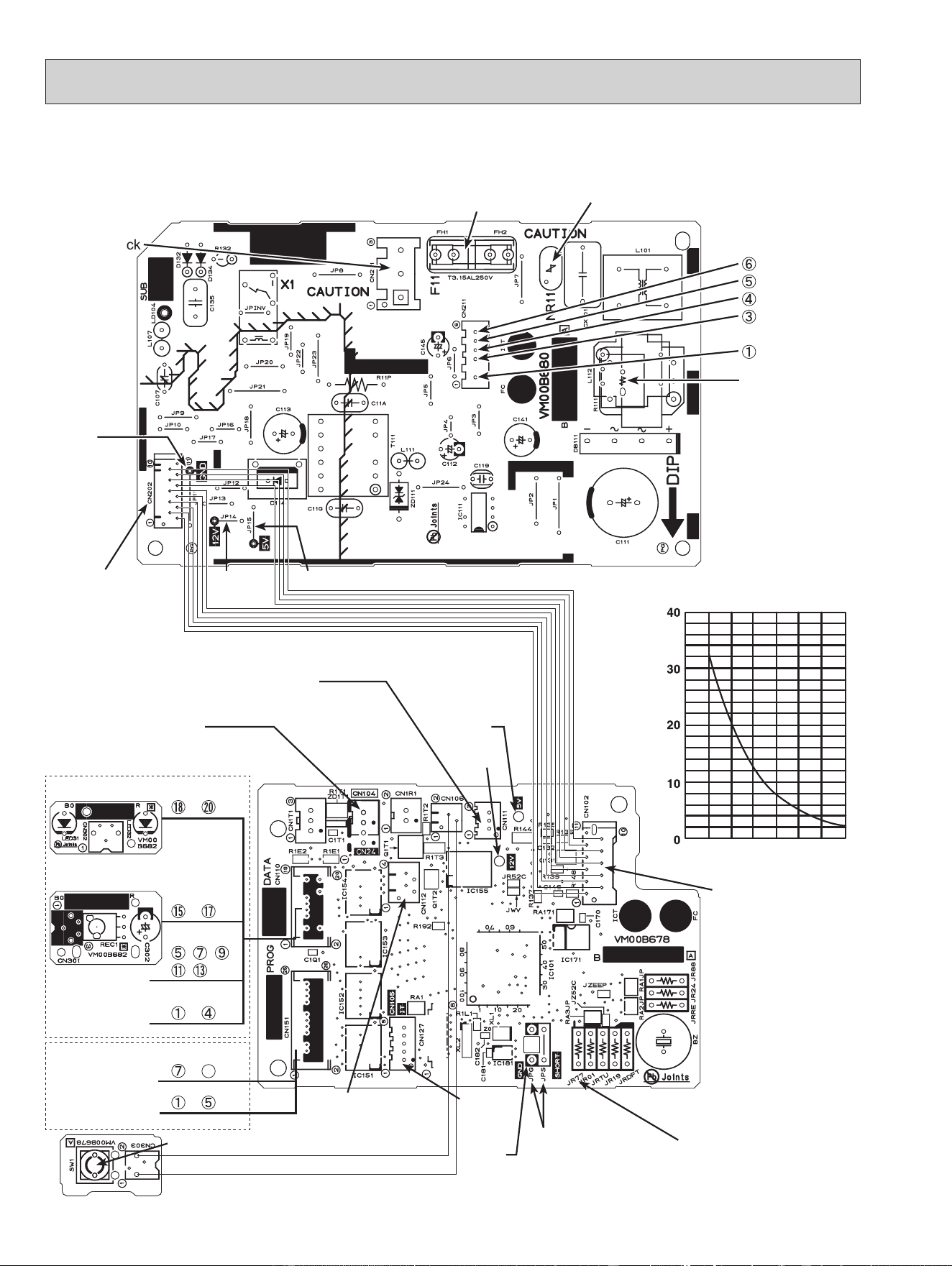
Indoor power P.C. board, Indoor electronic control P.C. board, Receiver board, Display board, Switch board
MSZ-FS06NA MSZ-FS09NA MSZ-FS12NA MSZ-FS15NA MSZ-FS18NA
32
Indoor electronic control P.C. board
Indoor power P.C. board
Fuse (F11)
Varistor (NR11)
Indoor fan motor
(CN211)
(+)0 or 15 VDC
(+)3-6 VDC
15 VDC
(–) GND (high-
voltage DC)
294/325 VDC
Connector
Terminal Block
(CN201)
Connector to indoor
electronic control
P.C. board (CN202)
Receiver board
(CN301)
Display board
Switch board
Resistor (R111)
GND
5 VDC
GND
Timer short
mode point
JPG JPS
(Refer to 7-1.)
To disable "Auto restart
function" cut the Jumper
wire to JR77. (Refer to 7-4.)
Emergency operation switch (E.O.SW) (SW1)
Connector to indoor
power P.C. board
(CN102)
Indoor coil thermistor
RT12, RT13 (CN112)
9-7. TEST POINT DIAGRAM AND VOLTAGE
12 VDC
5 VDC
i-see SENSOR
MOTOR MT
i-see sensor
~ pin
~ pin
, , ,
, pin
~ pin
CN110
Vane motor MV1
(horizontal)
Vane motor MV2
(vertical)
CN151
~ pin
~
26
pin
12 VDC
Room temperature
thermistor RT11 (CN111)
Connector cable (CN24)
Interface
(CN105)
Room temperature thermistor (RT11)
Indoor coil thermistor (RT12, RT13)
Temperature (°F)
Resistance (kΩ)
32
50 68 86 104 122 140
OBH872
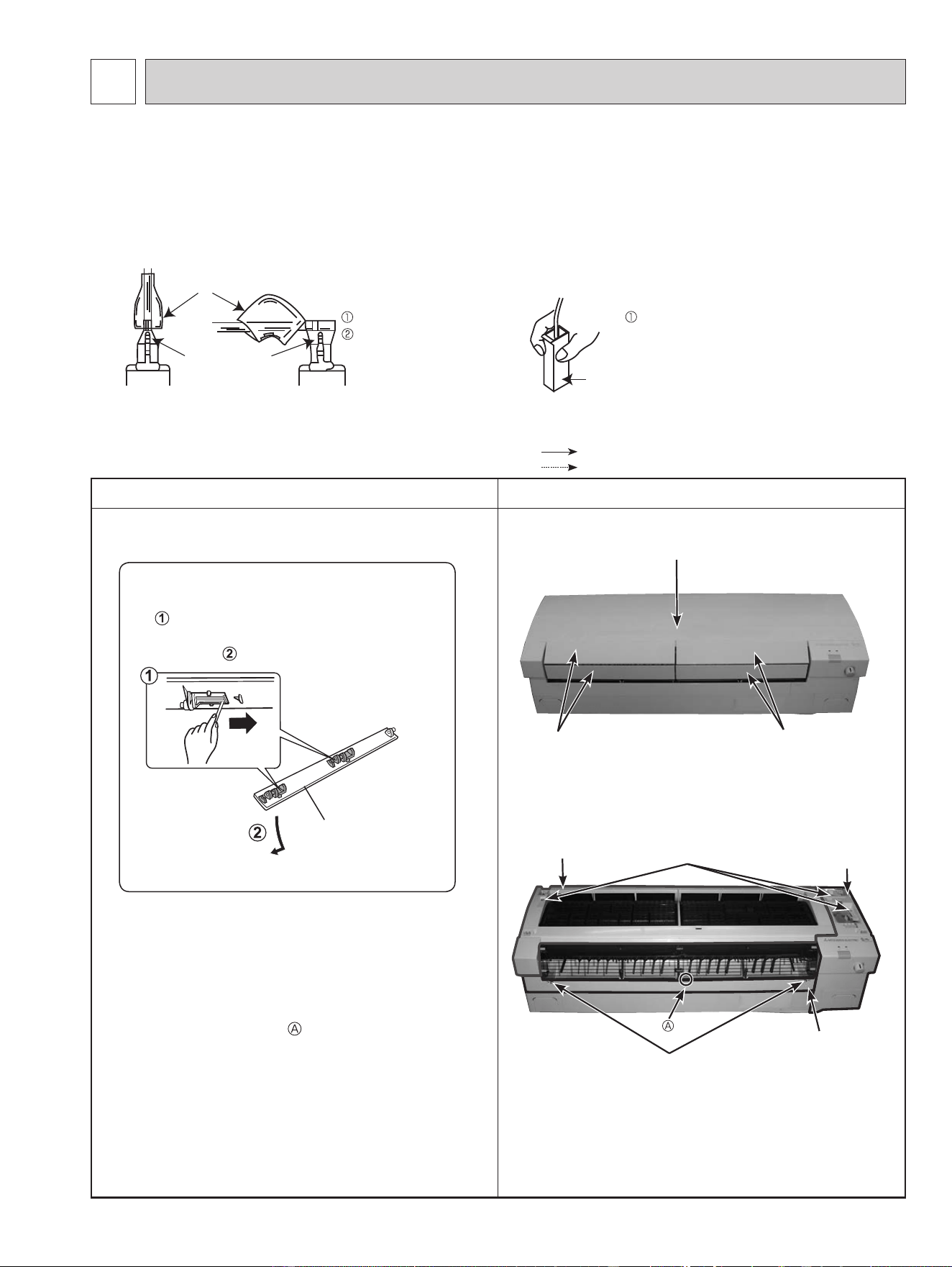
OPERATING PROCEDURE PHOTOS
1. Removing the panel
(1) Remove the horizontal vanes.
(2) Remove the front panel. Remove the screw caps of
the under panel. Remove the screws of the under
panel.
(3) Pull out the right top corner of the right panel and
remove the right panel.
(4) Pull out the left bottom corner of the left panel and
remove the left panel.
(5) Unhook the lower part
of the under panel and
remove the under panel.
Photo 1
Photo 2
10-1. MSZ-FS06NA MSZ-FS09NA MSZ-FS12NA MSZ-FS15NA MSZ-FS18NA
NOTE: Turn OFF the power supply before disassembly.
33
10
DISASSEMBLY INSTRUCTIONS
(1) Slide the sleeve and check if there is a locking lever or not. (2) The terminal with this connector has the
locking mechanism.
Slide the sleeve.
Pull the terminal while
pushing the locking
lever.
Hold the sleeve, and
pull out the terminal
slowly.
Connector
Sleeve
Locking lever
<"Terminal with locking mechanism" Detaching points>
The terminal which has the locking mechanism can be detached as shown below.
There are 2 types (Refer to (1) and (2)) of the terminal with locking mechanism.
The terminal without locking mechanism can be detached by pulling it out.
Check the shape of the terminal before detaching.
Removal procedure
Unlock
Upper and
lower vanes
Unlock the upper and lower vanes as shown
in using a thin instrument.
Then, remove the horizontal vanes in the
direction of .
Front panel
Horizontal vanesHorizontal vanes
Screws of the under panel
Right panel
Under panel
Screws of the panels
Left panel
: Indicates the visible parts in the photos/figures.
: Indicates the invisible parts in the photos/figures.
OBH872
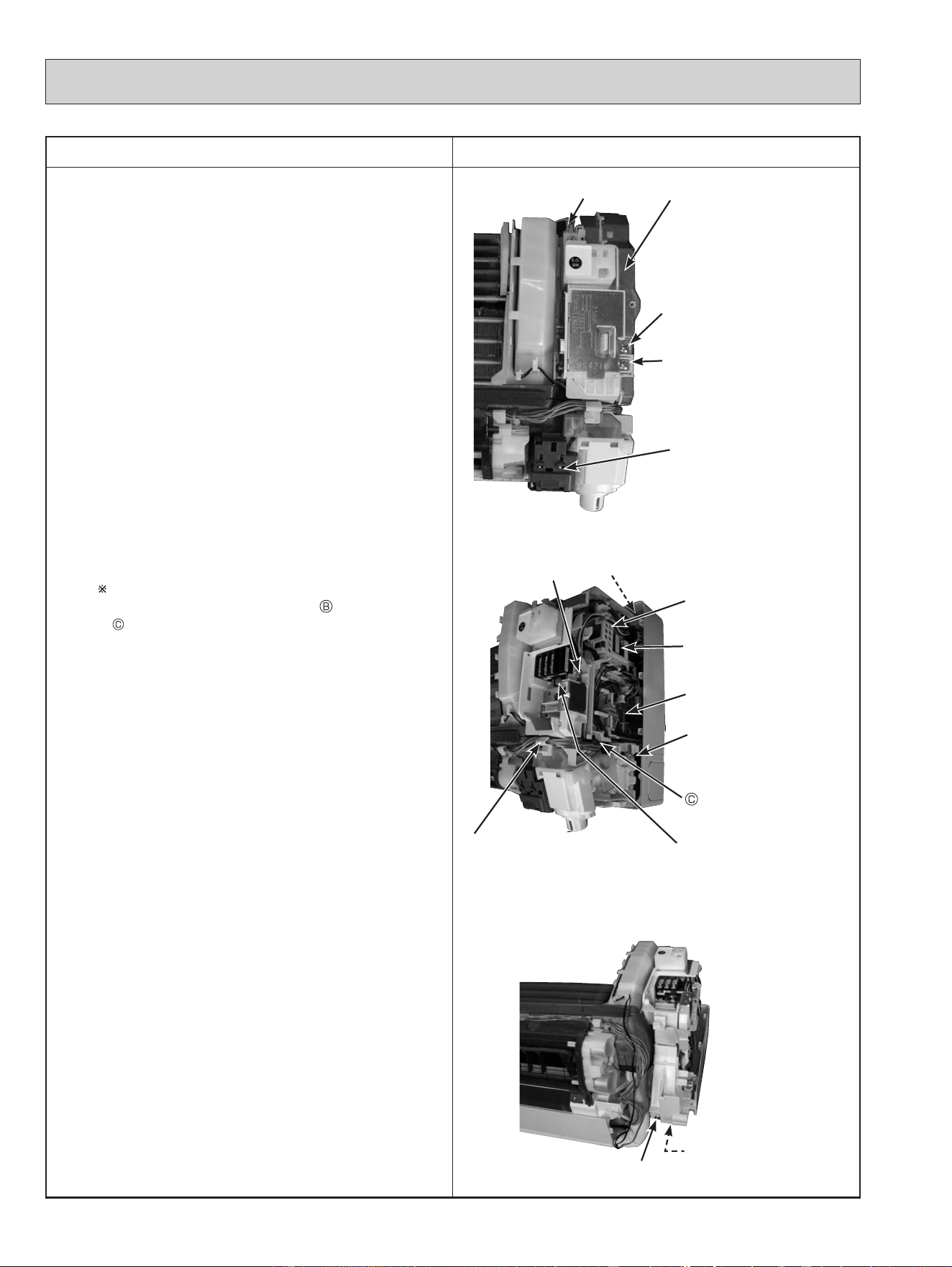
OPERATING PROCEDURE PHOTOS
2. Removing the indoor electrical box
(1) Remove the panels (Refer to section 1.) and the right
corner box.
(2) Remove the screw of the V.A. clamp and V.A. clamp.
(3) Remove the screw of the electrical cover and the
electrical cover.
(4) Disconnect following connectors:
<Indoor electronic control P.C. board>
CN151 (Vane motor)
<Indoor power P.C. board>
CN211 (Indoor fan motor)
CN110 (DISPLAY AND i-see SENSOR ASSEMBLY)
(5) Remove DISPLAY AND i-see SENSOR ASSEMBLY.
(6) Remove the screw of conduit cover and the conduit
cover.
(7) Remove the screw of conduit plate, the conduit plate
and the indoor/outdoor connecting wire.
(8) Remove the ground wire connected to the indoor heat
exchanger from the electrical box.
(9) Remove the screw fixing the electrical box, then
the upper catch of the electrical box, and
pull out the electrical box.
When installing the electrical box, pass the lead
wire from the fan motor through
(Photo 10) and
(Photo 4) so that it will not be pinched under the
electrical box.
Photo 3
Photo 4
Photo 5
34
Indoor power
P.C. board
Upper catch
Screw of
the V.A. clamp
DISPLAY AND i-see
SENSOR ASSEMBLY
Screw of
the electrical cover
Electrical box
Ground wire
Screw of
the terminal block
Ground wire
Indoor electronic
control P.C. board
Screw of
the electrical box
Catch of the DISPLAY AND
i-see SENSOR ASSEMBLY
Lead wire holder
Screw of the
conduit cover
Screw of the
conduit plate
OBH872
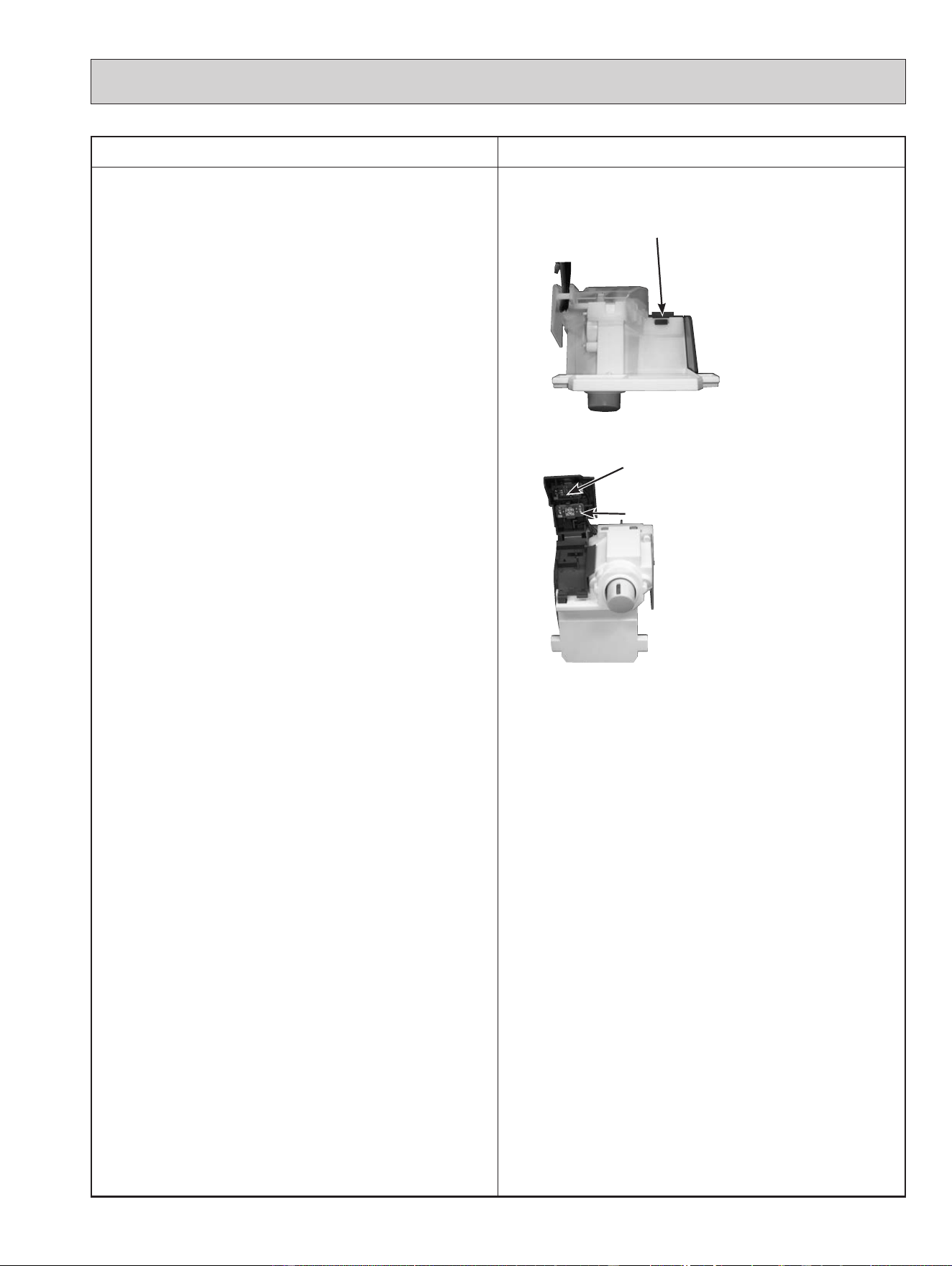
OPERATING PROCEDURE PHOTOS
3. Removing the indoor power P.C. board, the
switch board, the display board, the receiver
board and the indoor electronic control P.C.
board
(1) Remove the panels (Refer to section 1.) and the right
corner box.
(2) Remove the indoor electrical box (Refer to section 2.).
(3) Remove the ground wire connected to the electrical
box from the indoor power P.C. board.
(4) Disconnect the following connectors:
<Indoor electronic power P.C. board>
CN106 (Switch board)
CN201 (Terminal block)
CN202 (To the indoor electronic control P.C. board)
(5) Remove the lead wire holder.
(6) Remove the indoor power P.C. board.
(7) Disconnect the following connectors:
<Indoor electronic control P.C. board>
CN111 (Room temperature thermistor)
CN112 (Indoor coil thermistor)
(8) Unhook the catches of the DISPLAY AND i-see
SENSOR ASSEMBLY from the electrical box (right
side).
(9) Unhook the catch of the rear cover of the DISPLAY
AND i-see SENSOR ASSEMBLY, and open the rear
cover.
Remove the display P.C. board and the receiver P.C.
board.
(10)
Open the switch panel and remove the switch P.C.
board.
Photo 6
Photo 7
35
Catch of the DISPLAY AND
i-see SENSOR ASSEMBLY
Display P.C. board
Receiver P.C. board
OBH872
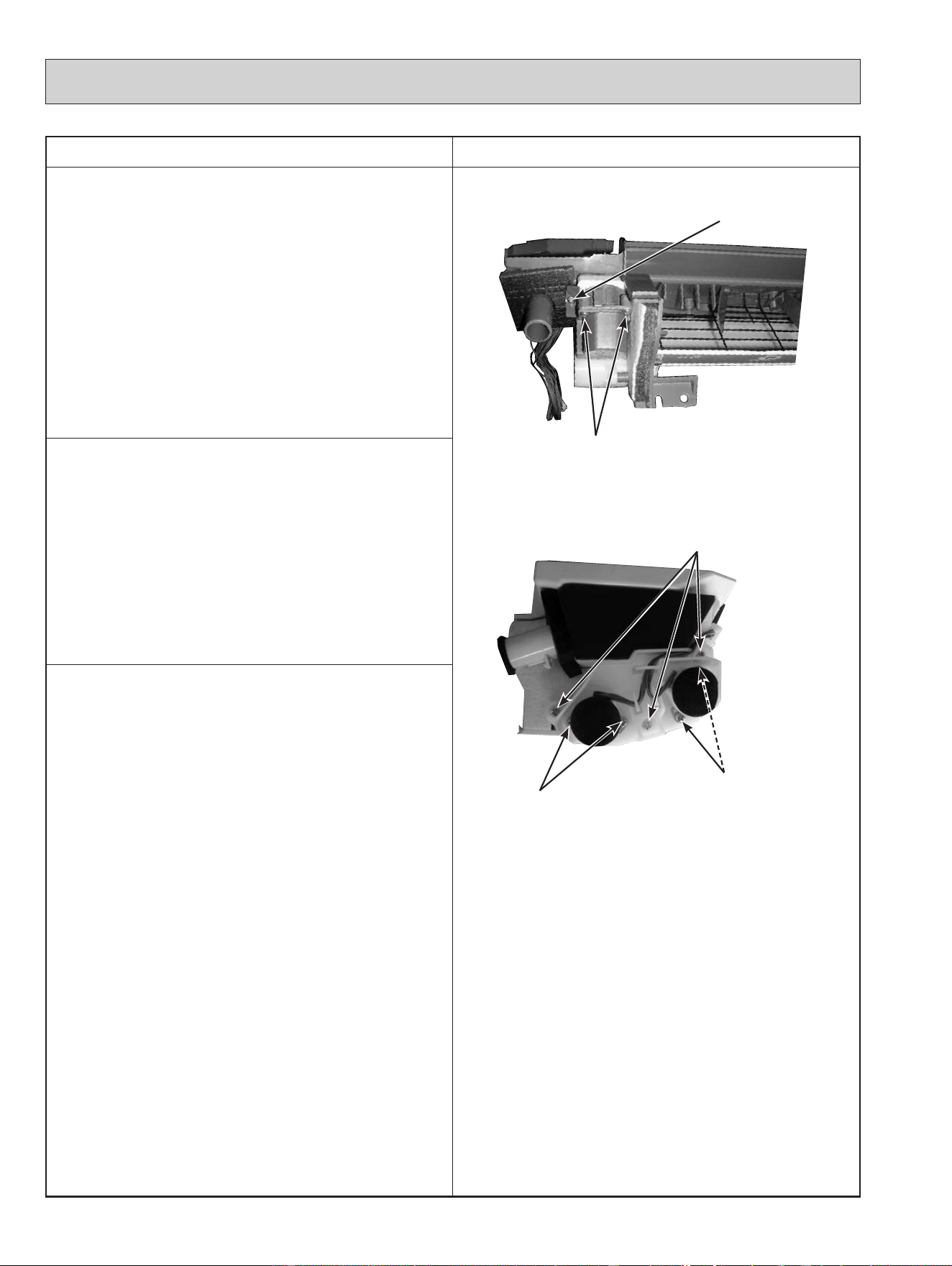
OPERATING PROCEDURE PHOTOS
4. Removing the nozzle assembly
(1) Remove the panels (Refer to section 1.) and the right
corner box.
(2) Remove the indoor/outdoor connecting wire (Refer to
section 2.).
(3) Remove the electrical cover (Refer to section 2.).
(4) Disconnect the following connector:
<Indoor electronic control P.C. board>
CN151 (Vane motor)
(5) Remove the DISPLAY AND i-see SENSOR
ASSEMBLY.
(6) Pull out the drain hose from the nozzle assembly and
remove the nozzle assembly.
(7) Remove the vane motors (Refer to section 5, 6.).
Photo 8
Photo 9
5. Removing the vertical vane motor
(1) Remove the nozzle assembly (Refer to section 4.)
(2) Remove the screw of the vertical vane motor unit, and
pull out the vertical vane motor unit.
(3) Remove the screws of the vertical vane motor unit
cover.
(4) Disconnect the connector from the vertical vane
motor.
(5) Remove the vertical vane motor from the vertical
motor unit cover.
6. Removing the horizontal vane motor
(1) Remove the nozzle assembly (Refer to section 4.).
(2) Remove the screws of the horizontal vane motor unit,
and pull out the horizontal vane motor unit.
(3) Remove the screws of the horizontal vane motor.
(4) Disconnect the connector from the horizontal vane
motor.
(5) Remove the horizontal vane motor from the horizontal
vane motor unit.
36
Screw of the vertical
vane motor unit
Screws of the vane
motor unit cover
Screws of the horizontal
vane motor
Screws of the
horizontal vane
motor
Screws of the
horizontal vane motor unit
OBH872
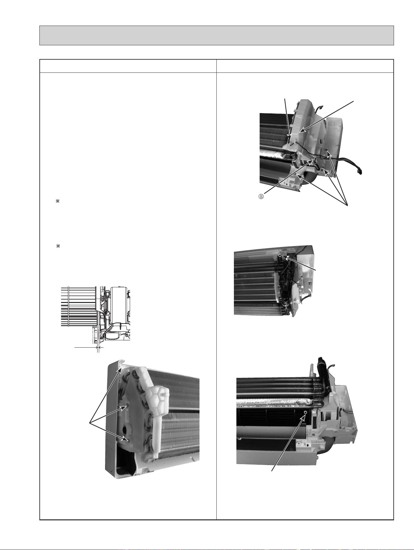
OPERATING PROCEDURE PHOTOS
7. Removing the indoor fan motor, the indoor coil
thermistor and the line flow fan
(1) Remove the panels (Refer to section 1.) and the right
corner box.
(2) Remove the indoor electronic control P.C. board
holder, the electrical box and the nozzle assembly.
(3) Remove the screws fixing the motor bed.
(4) Release the hooks of the water cut and remove the
water cut.
(5) Loosen the screw fixing the line flow fan.
(6) Remove the motor bed together with the indoor fan
motor and the motor band.
(7) Release the hooks of the motor band and remove the
motor band. Pull out the indoor fan motor.
(8) Remove the indoor coil thermistor from the heat
exchanger.
Install the indoor coil thermistor in its former position
when assembling it (Photo 10.).
(9) Remove the screws fixing the left side and the upper
right side of the heat exchanger.
(10)
Lift the heat exchanger, and pull out the line flow fan
to the lower left.
When attaching the line flow fan, screw the line flow
fan so 4 mm gap is provided between the right end of
the line flow fan and the right wall of the air passage
of the box (Figure 1).
Photo 10
Photo 11
Photo 12
Photo 13
Figure 1
4 mm
37
Water cut
Screws of
the motor bed
Lead wire of the indoor
coil thermistor
Screw of the line flow fan
Screws of
the left side of
the heat
exchanger
Screw of the upper right
side of the heat exchanger
OBH872
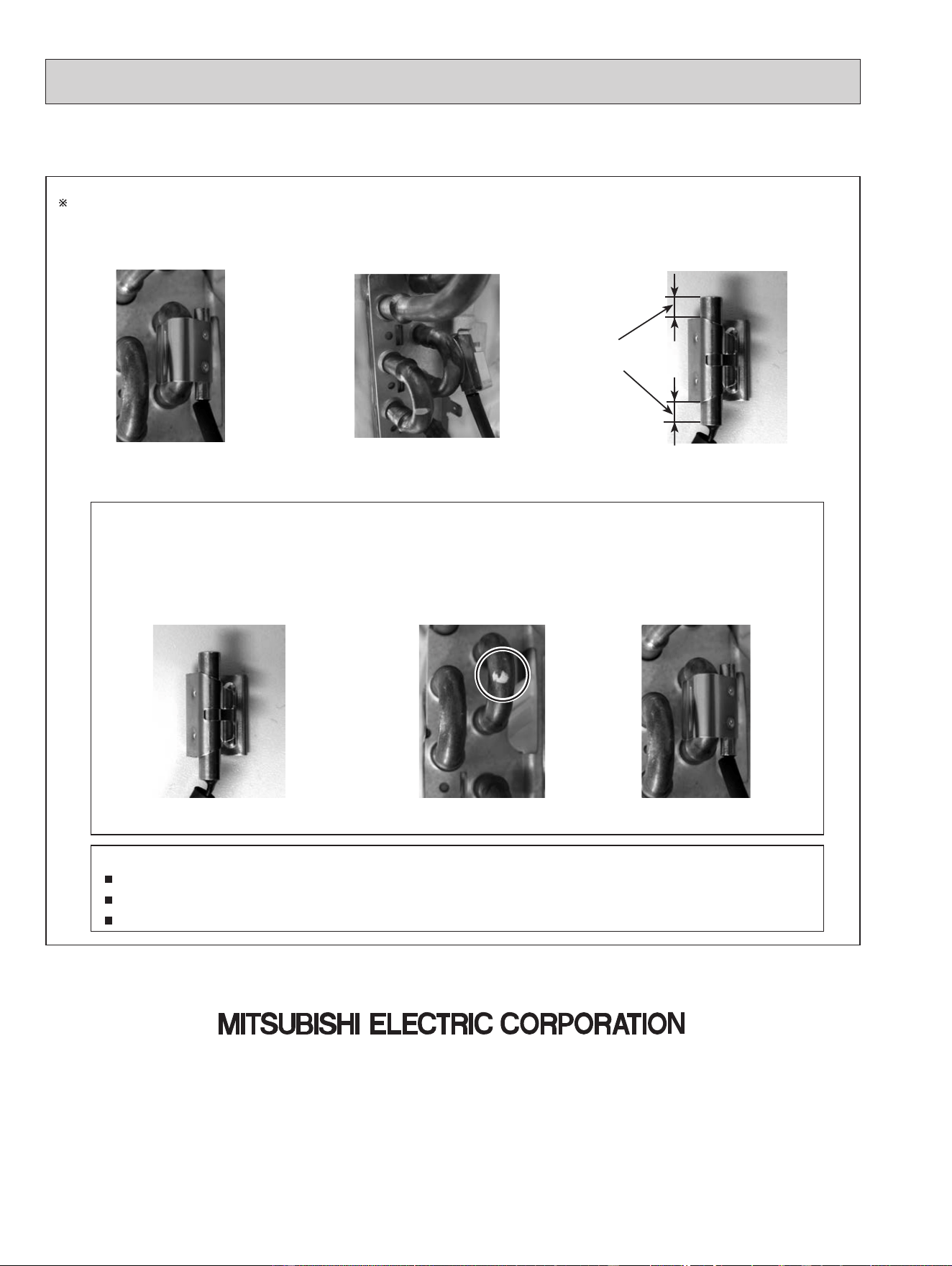
38
Fixing the indoor coil thermistor
There are 2 forms of parts for fixing the indoor coil thermistor.
NOTE:
Take care to avoid loss and accidental falling of the clip-shape part inside the unit.
Mount the clip-shape part on the marked position.
Do not pull the lead wire when removing the indoor coil thermistor.
Holder shapeClip shape
When fixing the indoor coil thermistor
to the clip-shape/holder-shape part, the
lead wire should point down.
1. Set the indoor coil
thermistor in the center of
the clip-shape part.
2. Check the (marked)
mounting position.
3. Mount the
clip-shape part.
Position and procedure for mounting the clip-shape part
About the
same length
Specications are subject to change without notice.
© Copyright 2020 MITSUBISHI ELECTRIC CORPORATION
Published: Nov. 2020. No. OBH872
Made in Japan
HEAD OFFICE: TOKYO BUILDING, 2-7-3, MARUNOUCHI, CHIYODA-KU, TOKYO 100-8310, JAPAN