JinKoSolar Photovoltaic Modules
Installation Manual
A1
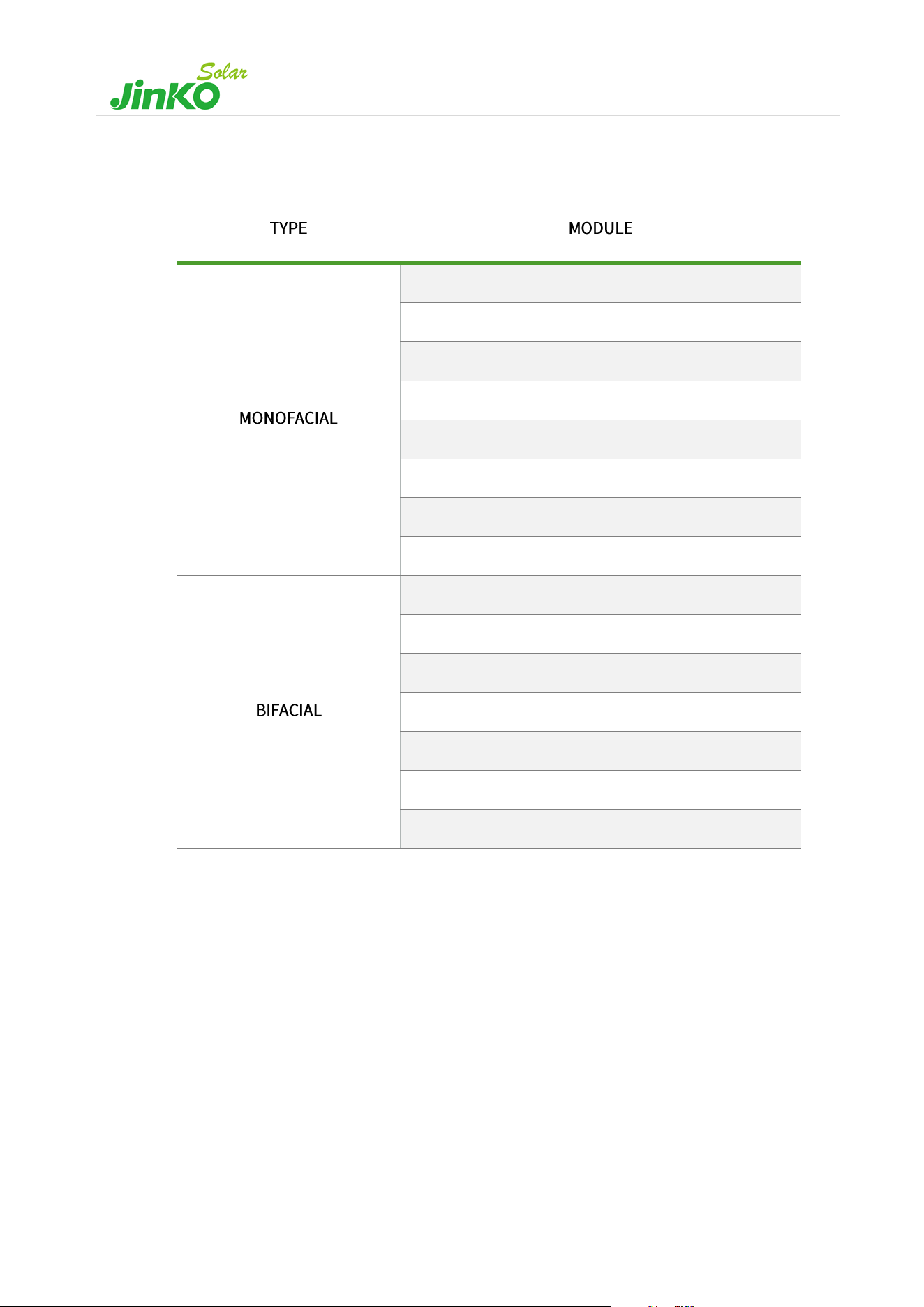
JKMxxxN-54HL4R-(V)
JKMxxxN-54HL4-(V)
JKMxxxN-54HL4R-B
JKMxxxN-60HL4-(V)
JKMxxxN-72HL4-(V)
JKMxxxM-72HL4-(V)
JKMxxxN-72HL4-(V)-L
JKMxxxN-66HL4M-(V)
JKMxxxN-54HL4R-BDB
JKMxxxN-72HL4-BDV
JKMxxxN-72HL4-BDX
JKMxxxM-72HL4-BDVP
JKMxxxN-78HL4-BDV
JKMxxxN-66HL4M-BDV
JKMxxxN-66HL5-BDV

Abbreviations
A: Amper. Unit of current.
AC: Alternating Current.
AR: Anti Reflection.
BIPV: Built Integrated Photovoltaic.
DC: Direct Current.
IEC: International Electrotechnical Commission.
IP: Ingress Protection.
mm: Millimeter. Unit of length.
m: Meter. Unit of length.
N: Newtons. Unit of force.
Nm: Newton meter. Unit of torque (moment).
Pa: Pascal. Unit of pressure.
pcs.: pieces. Number of items.
PPE: Personal Protective Equipment.
PV: Photovoltaic.
RH: Relative Humidity.
STC: Standard Test Conditions.
UV: Ultraviolet.

CONTENTS
1. Introduction ................................................................................................................................................................ 1
1.1 Rules and regulations ................................................................................................................................................... 1
1.2 Disclaimer ....................................................................................................................................................................... 1
2. General information .................................................................................................................................................. 2
2.1 Regular safety ................................................................................................................................................................ 2
2.2 Electrical performance safety ...................................................................................................................................... 3
2.3 Operation safety ............................................................................................................................................................ 4
2.4 Fire safety ....................................................................................................................................................................... 5
3. Installation conditions .............................................................................................................................................. 6
3.1 Climate/Environment conditions and Site selection ................................................................................................. 6
3.2 Tilt angle selection ......................................................................................................................................................... 6
4. Mechanical Installation ............................................................................................................................................. 7
4.1 Fixed installation-mounting with bolts ....................................................................................................................... 8
4.2 Fixed installation-mounting with clamps ................................................................................................................. 10
4.3 Tracker Installation ..................................................................................................................................................... 15
5. Electrical Installation............................................................................................................................................... 16
5.1 Electrical property ....................................................................................................................................................... 16
5.2 Wiring and cables ........................................................................................................................................................ 17
5.3 Grounding .................................................................................................................................................................... 19
6. Maintenance and care ............................................................................................................................................. 20
6.1 Visual Inspection.......................................................................................................................................................... 20
6.2 Cleaning ........................................................................................................................................................................ 20
6.3 Inspection of Connectors and Cables ....................................................................................................................... 21

1
1. Introduction
Thanks for choosing JinKoSolar photovoltaic (PV) modules (hereafter referred to as “modules”).
This manual provides important safety guidelines for the installation, maintenance, and use of the modules. To ensure
correct installation and stable power output, it is necessary to read and understand all installation instructions before
proceeding. As PV modules are power generation products, professional technicians must perform the installation and
adopt appropriate safety measures to avoid accidents
The protection class of the module: Class II (IEC61730:2023); (IEC61730:2016);
The application class of the module: Class A (IEC61730:2004);
Fireproof rating: Class C, in line with IEC61730-2 standard. JKMxxxN-72HL4-BDX has a Class A fire rating.
1.1 Rules and regulations
The mechanical and electrical installation of modules must comply with all local applicable regulations and codes,
including electrical norms, including construction codes and electrical connection requirements, as well as mounting
and other equipment instructions. Regulations may differ based on site-specific conditions, such as building roof
installation, vehicle applications, etc. Additionally, requirements may vary depending on the installed system voltage
(DC or AC). For specific terms, please contact your local authorities.
1.2 Disclaimer
JinKoSolar reserves the right to change the product specifications and this installation manual without prior notice.
We recommend that you refer to the JinKoSolar website (www.jinkosolar.com) for the latest product and
documentation information. JinKoSolar does not accept any responsibility for any loss, damage or expense arising
from the installation, operation, use or maintenance of the Module, as the use of this manual and the conditions under
which the Module is installed, operated, used, and maintained are beyond JinKoSolar's control.
JinKoSolar disclaims any liability for infringement of patents and third-party rights that may result from the use of the
products. Customers are not authorized to use any patents or patent rights, express or implied, by using JinKoSolar
products. The information in this manual is based on JinKoSolar's knowledge and experience which is believed to be
reliable, including but not limited to, the product specifications above, such information and related recommendations
do not constitute the terms of any warranty, express or implied.

2
2. General information·
There are two labels on the module which contain the following information:
1. Nameplate: Each module has a nameplate, which indicates the module type, the main electrical and safety
specification parameters, etc.
2. Serial Number and Bar Code Label: Each module has a unique serial number and bar code as a unique identifier,
which is laminated inside the module permanently. This label can be normally found in the front side of its corners,
and in the middle of the rear side of the module.
2.1 Regular safety
- Handle modules during deliveries and transport with care to avoid large shocks that could damage the assembly or
/and cause cracks in the cell.
- Do not apply excessive force or objects on the module surface, do not impact, and do not twist the module frame
to prevent cell damages and/or cell cracks.
- Do not use the modules to replace or partly replace roofs and walls of buildings. Follow your local regulations for
building integration of photovoltaics.
- Avoid touching or modifying any part of the modules unless explicitly authorized by JinKoSolar. Refrain from
removing, attempting to repair, or disassembling any component installed by JinKoSolar.
- Junction boxes and female-male connectors interconnections of the modules covered by this manual meet IP68
(IEC60529) requirements. However, they must be protected from prolonged direct sunlight and water immersions,
to ensure long-term reliability.
- Do not drill holes in the frame without authorization from JinKoSolar, as it may cause corrosion or other negative
effects.
- Do not lift modules using the attached cables or the junction box.
- Prohibit modules, junction boxes and connectors from coming into contact with unapproved chemicals: e.g., petrol,
oil, acetone, alcohol, film strippers, potting compounds, TBP, cleaning agents, herbicides, rust inhibitors, descaling
agents, etc. For more information, please contact JinKoSolar technical support department.
- Do not use junction boxes or connectors that are contaminated (with dust, corrosion, etc.), or broken modules.
- Do not stand (see Figure 1) or step on the module (see Figure 2) as there is a risk of damage to the modules and
injury to the user.
- Use appropriate protective equipment when installing modules to avoid direct contact, reduce the risk of electric
Figure 1
Figure 2
3
shock, and protect hands from sharp edges. This includes standard and insulated safety tools and equipment (safety
helmet, insulated gloves and rubber shoes, harness or belts, ladder, etc.).
- When installing or maintaining the PV system, please do not wear metal rings, watches or other metal products, to
avoid electric shock dangers or module damage.
- Do not use wet tools, and refrain from working in rain, snow or windy conditions.
- Modules should be stored at the project site with additional rain protection to avoid direct open-air placement
before they are installed.
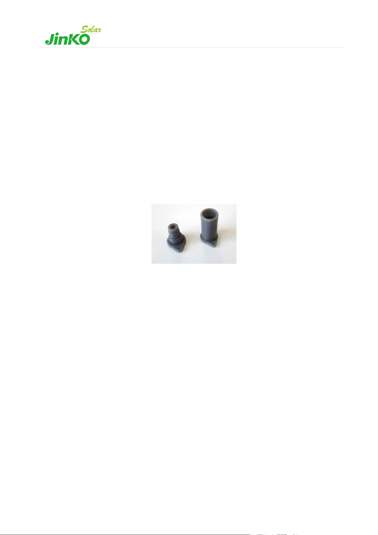
- In order to avoid external matter such as sand or water vapour from entering and causing connection safety problems,
once the modules are taken out of the box and installed, the connectors between the modules need to be connected
in time, and the connectors need to be kept dry and clean during the installation process. It is recommended to add
connector dust plugs (see Figure 3) as a temporary protective measure in areas with heavy dust, high salinity and
pollution, but long-term use (within 1 month) is not recommended.
Figure 3 connector dust plugs
2.2 Electrical performance safety
- Modules generate DC electrical energy when exposed to sunlight or other light sources. Improper contact with live
parts, such as terminals, may result in burns, sparks, and lethal shock.
- Breakage, opening the module to the exterior, of the front or rear glass can cause an electrical safety hazard, electric
shock, or fire. These modules cannot be repaired and must be removed and replaced immediately.
- Electrical specifications shown in datasheets are measured under Standard Test Conditions (STC), thus: Irradiance
1000W/m², module cell temperature 25ºC, air mass = 1,5. The current and voltage generated by modules in different
environments are different from measured at STC. Therefore, when determining the specifications of the rated
voltage, cable capacity, fuse capacity, controller capacity, and other output power related specifications, take the
values of 1,25 times the short-circuit current and open-circuit voltage marked on the module. This multiplier serves
as a reference and is commonly used; however, it is important to consult with your inverter/controller supplier for
system configuration design, as local regulations may vary, impacting these considerations.
- Snow, water, or other reflective medium in surrounding environments that intensify light reflection will increase
output current and power. And module voltage and power will increase under low temperature condition.
- Artificially concentrated sunlight shall not be directed on the module. Do not expose the back of the monofacial
module directly to sunlight.
- To prevent arcs and electrical shocks, do not disconnect modules under load without authorization; if disconnecting
the connector is needed, turn off DC and AC inverters or cut off the main switch of the converter first.

4
- PV module operation can only be stopped when they are kept from sunlight or covered by hard board (opaque
material) or UV-proof materials.
- When connecting a battery storage system, follow the battery manufacturer's instructions for correct installation,
operation, and maintenance to ensure system operation and user safety.
- Due to the risk of electrical shock, do not perform any work if the terminals of the module are wet.
- Do not operate on wet modules, if this is needed, only by wearing PPE.
- Please follow the cleaning requirements in this manual when cleaning modules, refer to section 6.2.
- Only the modules of the same size and the specifications within same range can be connected in series.
- The number of modules that can be connected at a PV installation shall be determined by a qualified institution or
person in accordance with the design specifications of the photovoltaic system and the local electrical design
specifications.
- Connect the male and female connectors correctly, before connecting, always ensure that the contacts are corrosion
free, clean, and dry; Check the wiring condition, all wires shall not be detached from the modules, and secure the
wires with cable ties so that the wires do not scratch or squeeze the rear side of the module.
- Do not touch the module, junction box or the connectors with bare hands during installation or under sunlight,
regardless if the module is connected to or disconnected from the system. The glass surface and the frame may be
hot, posing a risk of burns and electric shock.
- Do not insert any metal object into the connector.
- Keep connectors dry and clean, ensuring they are in good operating condition.
2.3 Operation safety
- Read and follow the manual“Handling, Storage and Unpacking Instructions”to ensure proper management of the
pallets. Custom unpacking methods are prohibited.
- Before unpacking, please check the product type, power bins, serial number, and relevant suggestions on the paper
of the packaging box.
- It is recommended to use art knife or cutter to remove the packing belt and wrapping film. Violent removal is
prohibited to avoid scratching the modules in the box.
- Ensure a proper environment before unpacking as well as enough man force (2 people minimum) to prevent the
module from slipping and hitting other modules, causing scratches, cracks, or deformation on the modules.
- Once the modules are removed from the pallet, they shall be promptly installed and connected to the inverter. If
they are not installed immediately, protective measures (such as adding rubber joint cover, etc.) must be taken on
the connectors' head to prevent water vapour, sand, dust, insects, or other contaminants from getting inside the
connector and causing poor contact or corrosion of the connector.
- When inspecting PV modules with AR coating technology, it will be normal to observe modules with a slight color
difference at different angles.
- Thermal expansion and contraction effects occur on the modules. During installation, the distance between two
adjacent modules must be ≥ 10mm. If there are special requirements, please confirm with JinKoSolar before
5
installation.
- During the installation, as for module removal, maintenance, and any other related processes, it is recommended
that the force applied between the cable and the connector, and the cable and the junction box, is not more than
60N.
- Meaning of crossed – out wheeled dust bin:
Do not dispose of electrical appliances as unsorted municipal waste, use separate
collection facilities.
Contact your local government for information regarding the collection systems
available.
If electrical appliances are disposed of in landfills or dumps, hazardous substances
can leak into the groundwater and get into the food chain, damaging your health and well-being.
When replacing old appliances with new ones, the retailer is legally obligated to take back your old appliance
for disposals at least free of charge.
2.4 Fire safety
- Please use appropriate module components to comply with local laws and regulations, as well as the building fire
safety requirements before installation, such as fuses, circuit breakers and grounding connectors, etc.
- JinKoSolar modules fire rating is set according to IEC61730-2:2023 standard, and it can be found in the
corresponding certificates. The Fire Class Rating of a module for roof mounted system shall meet local code
requirements in order to achieve the specified System Fire Class Rating for a non-BIPV module. All PV systems have
limitations of inclination required to maintain a specific System Fire Class Rating.
- For roof-top installations, it is responsibility of the designers or installers to ensure that the roof is suitable not only
in terms of the structural load-bearing capacity, but also the fire resistance for the installation of the PV modules in
accordance to local regulation.
- Make sure that the rear side of the module and the mounting surface are fully ventilated. When To facilitate
ventilation and heat dissipation of the module, the minimum distance between back side of the modules and roof
must be ≥ 10cm, considering the normal physical phenomenon which the modules will be concave to varying
degrees due to the gravity. The minimum clearance of any modules applied for special cases, please contact
JinKoSolar's technical support department.
- Different roof structures and installation modes will affect fireproof performance of buildings. Improper installation
may lead to the risk of fire.
- Do not install the modules anywhere close to open flames or flammable materials (hay, straw, wood, solvents, oils,
etc.), or exposed to flammable and explosive gases.
6
3. Installation conditions
3.1 Climate/Environment conditions and Site selection
The recommended weather conditions for installing modules are:
a) Humidity: < 85% RH
b) Ambient air temperature range: -40°C to +40°C
c) Operating temperature: -40°C to +70°C
In most applications, JinKoSolar PV modules should be installed in a location where they can receive maximum sunlight
throughout the year. In the Northern Hemisphere, the module should face south, and in the Southern Hemisphere, the
modules should face north. Modules facing 30 degrees away from due South (or due North) will lose approximately
10% to 15% of their power output. If the module faces 60 degrees away from due South (or due North), the power
loss will be 20% to 30%. Refer to the longitude and latitude of the location to determine the optimal azimuth of the
module.
The maximum altitude of module installation is 2000m.
JinkoSolar standard PV modules have passed the IEC 61701:2020 salt spray corrosion test (method 6). In the case
modules are installed within 50m to 500m from the seashore, the connectors shall be protected, i.e., adding dust plugs.
After removing the dust plugs, connect the connectors immediately and take other anti-rust measures to prevent rust.
Offshore PV modules are recommended if installation within 50 metres is required, please consult JinKoSolar for details.
Do not install the PV module in a location where it would be immersed in water or continually exposed to water from
a sprinkler or fountain, etc. When choosing a site, avoid trees, buildings or any other obstruction that could create
shadows on the modules at any time throughout the year. Shading causes loss of power output and may affect the
optimum performance and safety issue of the PV modules.
It is possible that modules installed with restricted airflow are not allowed for use in some hot locations, depending
on system design parameters. Installers should assess if the system design at a specific geographic location will result
in a 98th percentile module operating temperature
1
greater than 70°C, and must consider and avoid these factors in
design of systems.
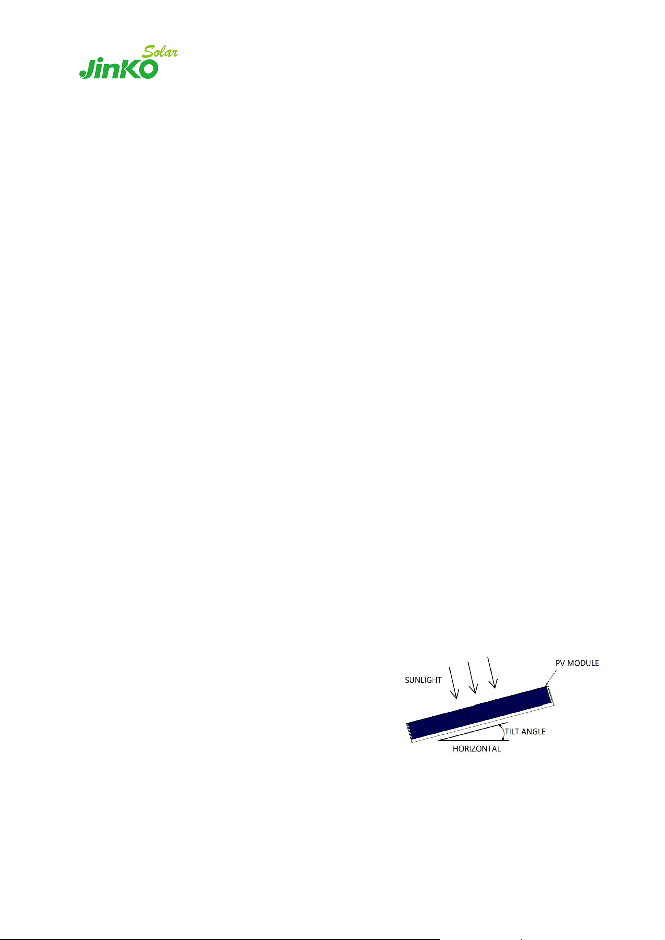
3.2 Tilt angle selection
The tilt angle of the PV module is measured between the surface of the PV module and a horizontal surface (see Figure
4). The module generates maximum output power when directly facing the sun.
For standalone systems, the tilt angle of the modules should be selected
to optimize the performance based on the season and sunlight. In
general, if the module output is adequate when the irradiance is low
(i.e., winter), the angle chosen should be adequate during the rest of the
year. For grid-connected systems, modules should be tilted at the angle
that the energy production from the modules will be maximized
on an annual basis.
1
98
th
-percentile temperature: represents the temperature that is larger than 98% of all the temperatures, and consequently it is met or exceeded only 2% of the time. It is to be
determined from measurements taken on hourly-basis, or more frequently. For a standard year, the temperature that a module would be expected to equal or exceed for 175,2 h
per year, is less than 70 °C.
Figure 4 PV module tilt angle

7
4. Mechanical Installation
Modules can usually be mounted by using the following methods: fixed installation-mounting with bolts, fixed
installation-mounting with clamps and tracker installation.
﹡Notes:
- All installation methods herein are only for reference, and they are based on the test results from third-party tests
and JinKoSolar internal tests. While we extensively test various mounting scenarios, the vast diversity in materials
and designs globally, including special profiles, makes it impossible to guarantee exact load specifications for
installations with unique materials or designs. Special designs, should be tested by the mounting companies, to
ensure the reliability of the systems.
- JinKoSolar will not provide related mounting accessories.
- the system installer or trained professional personnel must be responsible for the PV system's design, installation,
and mechanical load calculation and system security. The design must take into consideration module’s
bent/torsion, frame dimensions, fixation holes location and any other mechanic characteristic.
- Before installation, the following items shall be addressed:
a) Visually check the module for any damage. Clean the module if any dirt or residue remains.
b) Check if module serial number stickers match.
- The maximum loads that different types of modules can withstand on the front side and back side are dependent
on installation methods, which can be referred to Table 2 and 5-7. If there is heavy snow and strong wind on the
module installation site, take special protection to meet the actual requirements.
- All load values provided in this manual are maximum test load values, measured in Pa and describe as follows:
Maximum Test Load = 1.5 (Safety factor) x Design load
- The module must be mounted on the bracket according to the following installation. If there are other installation,
please consult JinKoSolar and obtain approval, otherwise the warranty will be invalid.
- Under the mounting method of the fixed bracket as specified in this manual, the modules will be concave to
varying degrees due to the gravity, which is a normal physical phenomenon and does not affect the normal use
and performance of the modules. Any other external forces will cause additional sinking of the modules, so any
operation of the modules should comply with this manual.
8
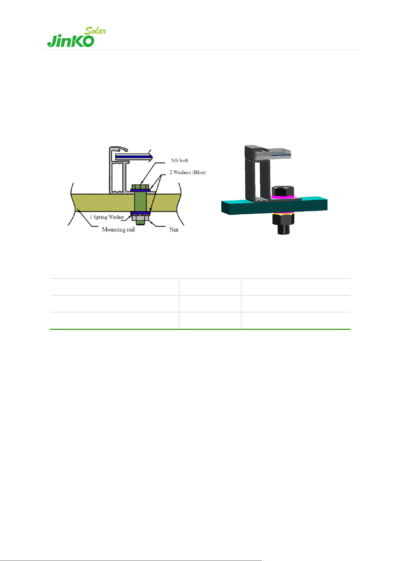
4.1 Fixed installation-mounting with bolts
Install the module on the rack using anti-corrosion bolts, elastic washers and flat washers with sufficient torque to
allow the module to be properly secured. See Figure 5 (a) and (b) for detailed installation information.
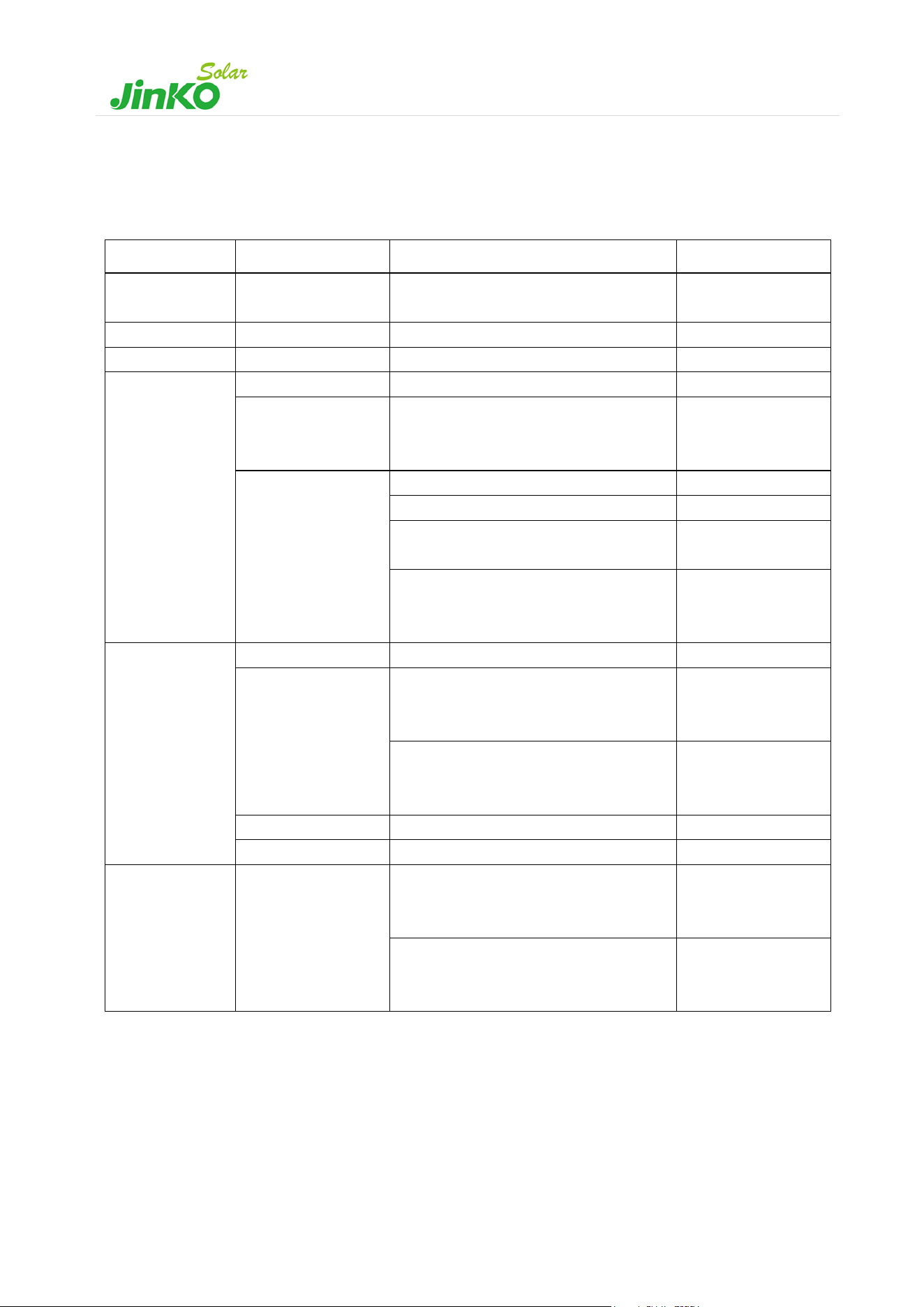
Table 1 lists different sizes of bolts for different mounting holes, along with torque recommendations. However, it is
crucial to consult the installer or bracket supplier to obtain the exact torque value for your specific installation.
(a) (b)
Mounting hole (mm)
Bolt size
Reference torque ( Nm )
14 x 9
M8
16-20
10 x 7
M6
9-12
Table 1 Bolts for different mounting holes
Figure 5 Mounting with bolts (a) schematic (b)3D design of the installation with bolts
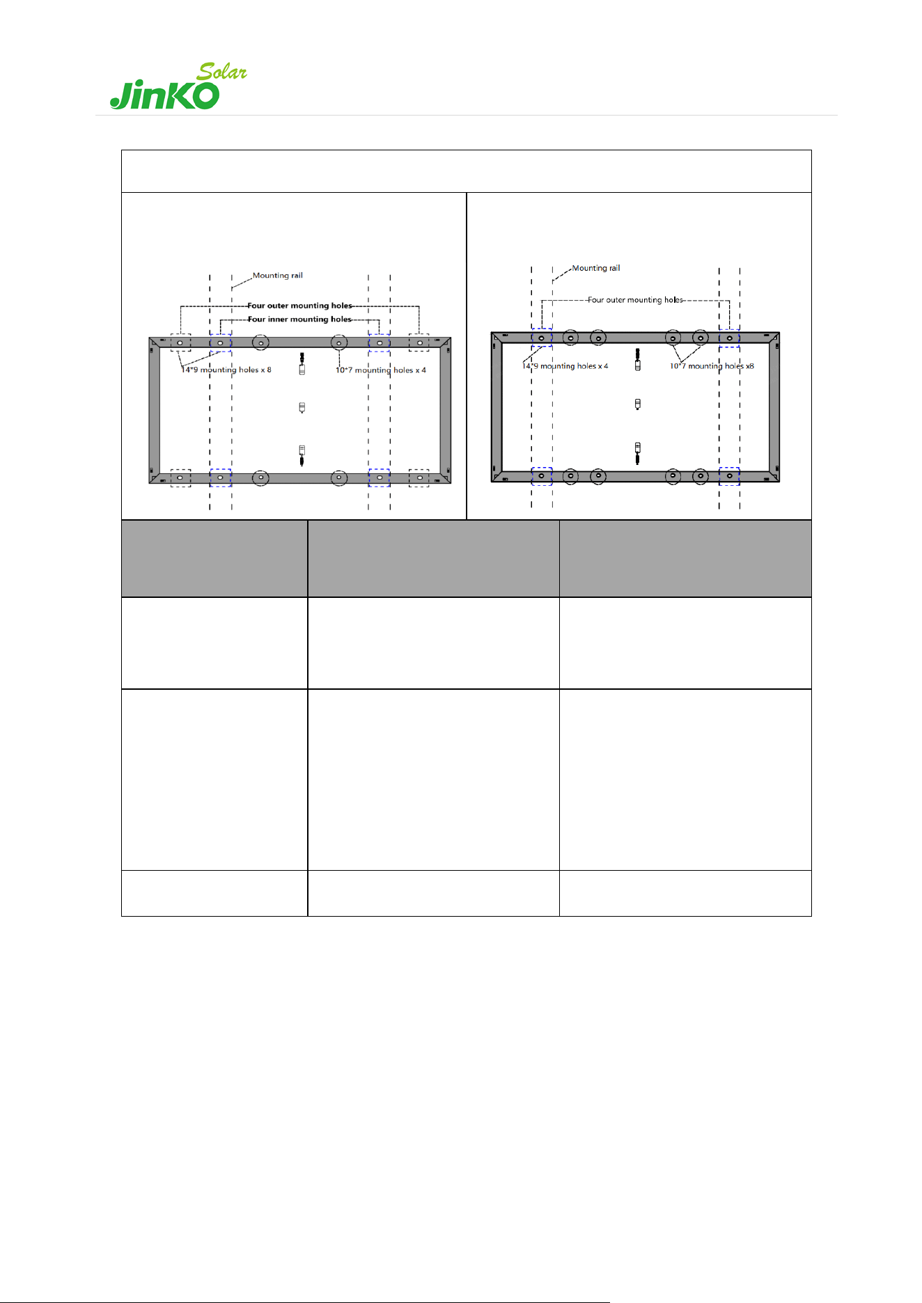
9
Bolting installation
Installation with bolts
(Four inner mounting holes)
Installation with bolts
(Four outer mounting holes)
Module type
(JKMxxx…)
Four inner mounting holes
(Maximum Test Load Pa)
Four outer mounting holes
(Maximum Test Load Pa)
N-54HL4R-(V)
N-54HL4R-B
N-54HL4R-BDB
N-72HL4-BDX
+6000/-4000
/
N-78HL4-BDV
N-72HL4-(V)
N-72HL4-(V)-L
N-72HL4-BDV
N-60HL4-(V)
M-72HL4-BDVP
M-72HL4-(V)
M-72HL4-TV
+5400/-2400
/
N-66HL4M-BDV
N-66HL4M-(V)
/
+5400/-2400
Table 2 Test loads for inner and outer four-hole mounting for different modules
Notes:the figures show mounting rails parallel to the short side of the module. If special mounting system or special
installation method is required, please verify the torque and material compatibility with the supplier of the racking
system.
10
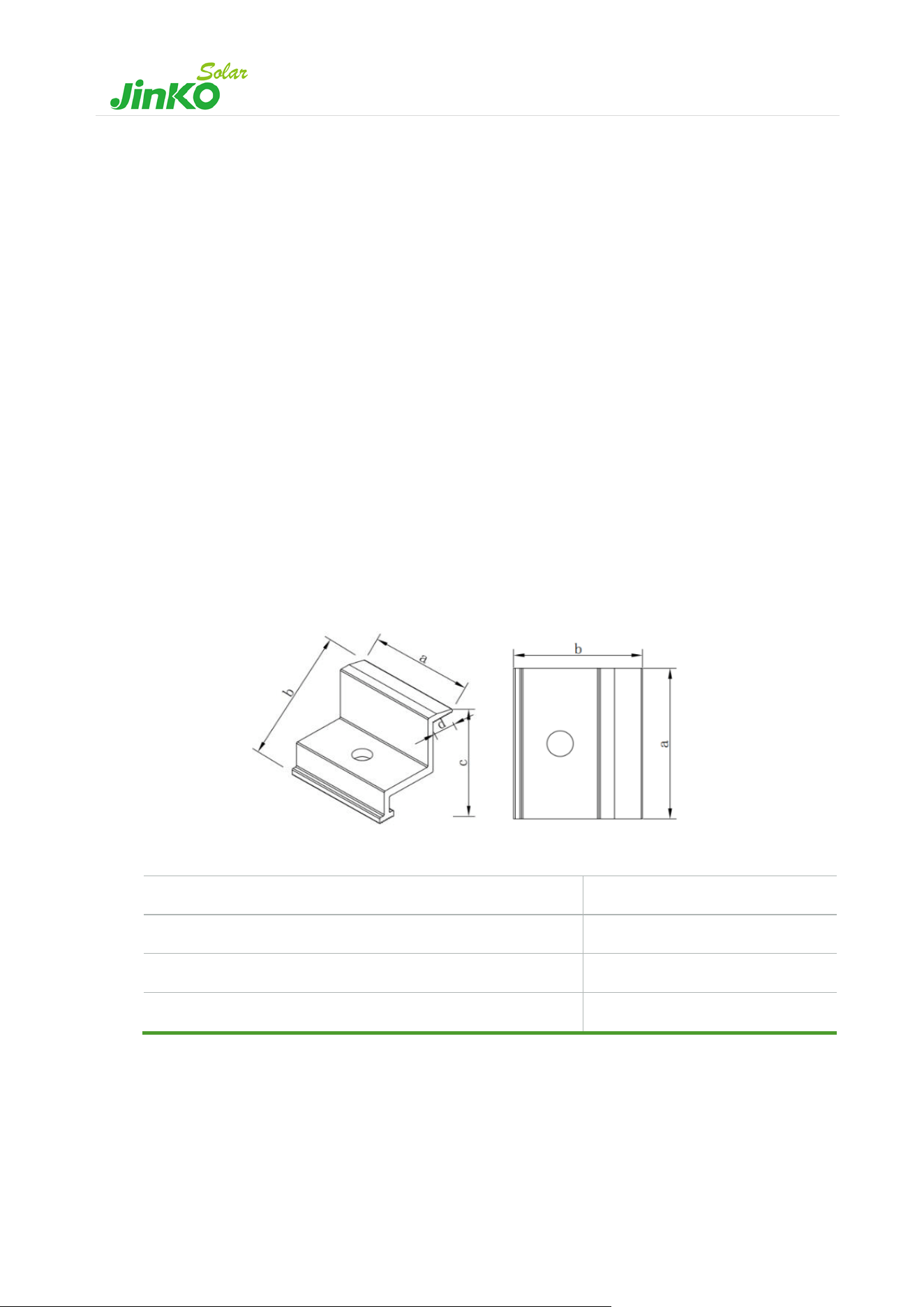
4.2 Fixed installation-mounting with clamps
The clamps must not be installed in contact with the front glass of the module and must not deform the module frame.
Recommended clamp schematic shown as followed (see Figure 6). Ensure that the clamps do not create a shadow on
the module. Under no circumstances may the frame be altered. When choosing the mounting method for the clamps,
make sure that there are at least four clamps on each module. Different mounting positions of the clamps determine
the maximum load capacity of the module. Table 5-7 as followed show the different mounting methods and the
positions of the clamps for the different mounting methods. The distance between the installation position of the long-
side clamp and the edge is represented by L in Table 5-7. The distance between the installation position of the short-
side clamp and the edge is represented by S in Table 5-7.
Depending on the local wind and snow loads, if there is a possibility of excessive load combinations:
a) Additional clamps could be required to ensure that the module has enough load carrying capacity. Clamp
dimensions, contact area and torque must follow minimum values shown in Table 3.
b) Longer and/or stronger profiles/rails could be required to ensure that the module has enough load carrying
capacity.
The torque value applied during installation of the clamps should be high enough to securely hold the module. Please
always consult the installer or bracket supplier for exact torque value.
Length of the clamp (a)
≥50 mm
Thickness
≥3 mm
Overlap of the frame of the module (d)
10-11 mm
Torque
16-20 Nm (M8 bolt)
Table 3 Minimum values for clamp dimensions, contact area and torque
Figure 6 Recommended clamp schematic
11
The minimum dimensions of clamps specified in this installation manual have been tested and verified through the
installation process and serve as a baseline for proper installation. However, it is important to note that these minimum
values may not guarantee compatibility with all variations of clamps that may exist in the market. Using clamps with
dimensions lower than the recommended minimums may result in insufficient clamping force and compromise the
integrity of the installation.
It is important to ensure that any alternative clamps used in the installation meet the necessary performance standards
and do not compromise the safety and integrity of the system.
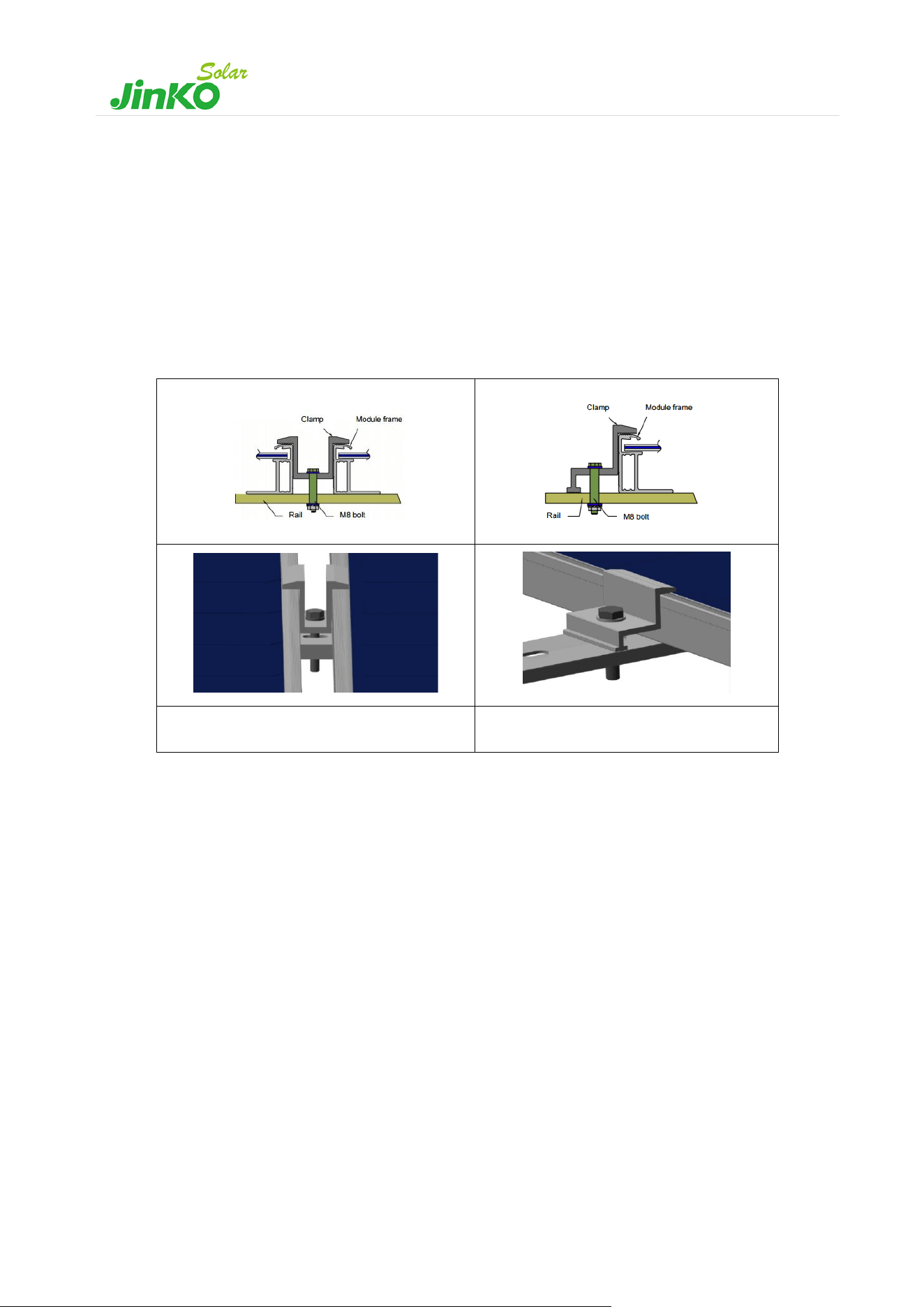
Middle clamp module installation
End clamp module installation
Table 4 PV module installed at the side with Clamp mounting
Please thoroughly review the maximum test load specified for each module type, contingent on the chosen installation
method.
12
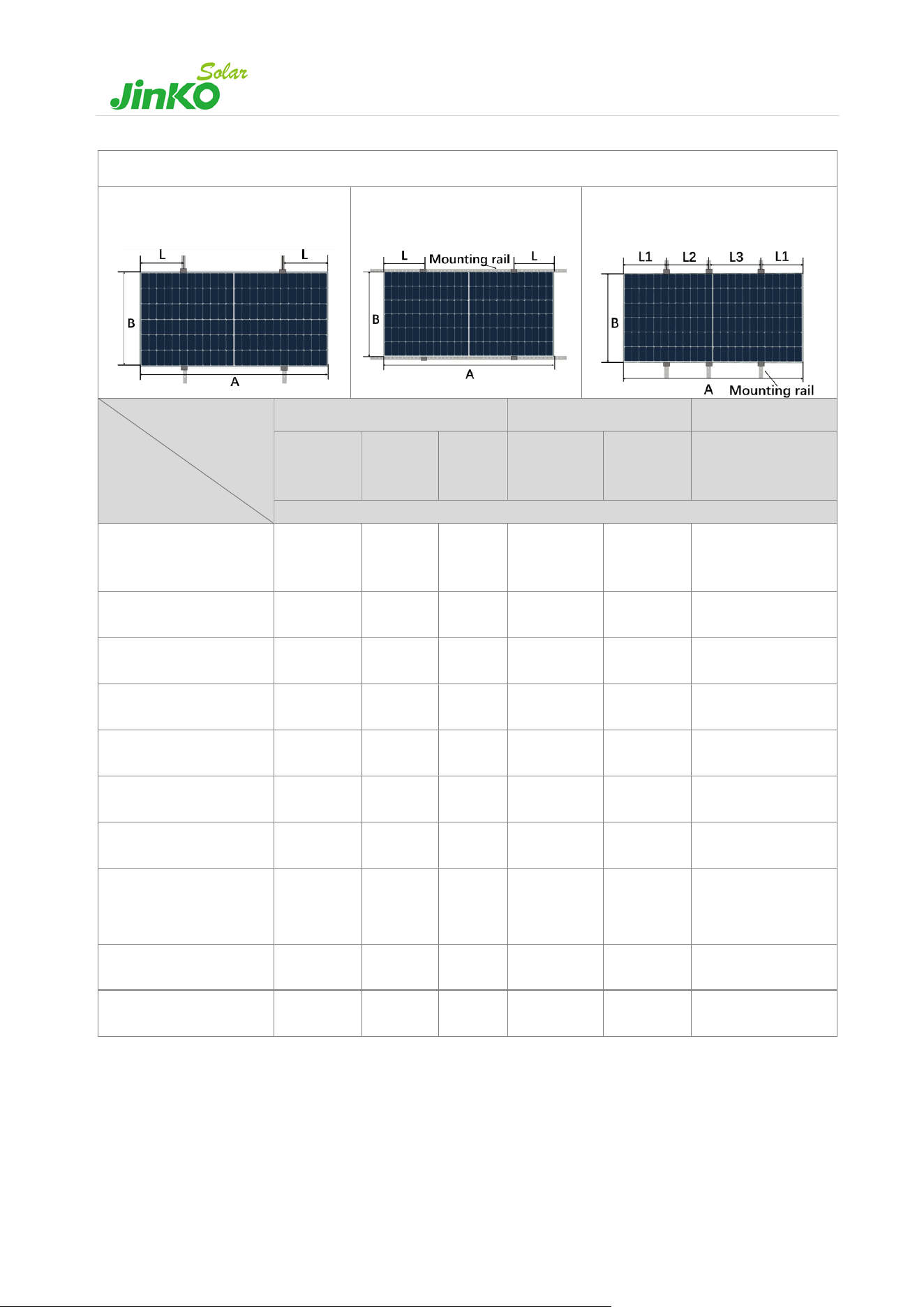
Long side clamping (with rails)
Method A
Long side clamping (4pcs.), rails
(2pcs) parallel to short side.
Method B
Long side clamping (4pcs.), rails
(2pcs) parallel to long side.
Method C
Long side clamping (6pcs.), rails
(3pcs) parallel to short side.
Mounting method
/Range
Module Type
/ Height
Method A
Method B
Method C
L=
A/4±50
L=A/5~
A/4
L=
A/5±50
L= A/4±50
L=
A/5±50
L1=450
L2=(A/2-L1+50)
L3=(A/2-L1-50)
Maximum test load (Pa)
N-54HL4R-BDB
N-54HL4R-(V)
N-54HL4R-B
/
/
+6000
/-4000
/
/
/
N-54HL4-(V)
/
/
+6000
/-4000
/
+2400
/-2400
+6000
/-3000
N-60HL4-(V)
/
/
+5400
/-2400
/
+2400
/-2400
/
N-66HL4M-BDV
/
+5400
/-2400
/
/
/
/
N-66HL4M-BDX
N-72HL4-BDX
+6000
/-4000
/
/
/
/
/
N-66HL4M-V
N-72HL4-(V)-L
/
+5400
/-2400
/
/
/
/
N-72HL4-(V)
M-72HL4-(V)
/
+5400
/-2400
/
/
/
/
N-72HL4-(V)(B35)
M-72HL4-(V)(B35)
/
+5400
/-2400
/
/
/
+5800
/-2400
N-72HL4-BDV
M-72HL4-BDVP
+5400
/-2400
/
/
+3000
/-2400
/
/
N-78HL4-BDV
+5400
/-2400
/
/
+2800
/-2400
/
/
Table 5 Maximum test load values for different modules with long side clamps mounted with rail
13
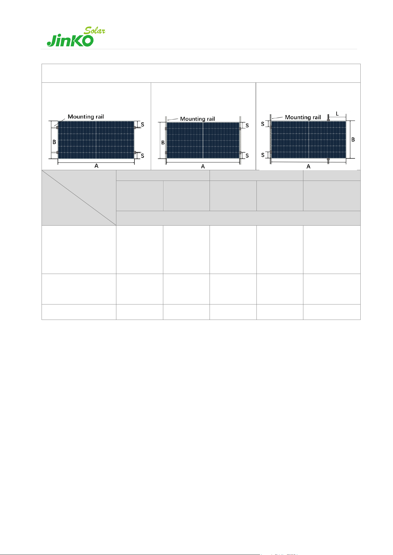
Short-side clamping/long-side and short-side clamping (with rails)
Method D
Short side clamping (4pcs.), rails (2pcs)
parallel to long side.
Method E
Short side clamping (4pcs.), rails
(2pcs) parallel to short side.
Method F
Short& long side clamping (4pcs.),
rails (2pcs) parallel to short side.
Mounting method
/Range
Module Type
/ Height
Method D
Method E
Method F
S=130-240
S=100-240
S=130-240
S=100-240
S=100~240
L=A/5±50mm
Maximum test load (Pa)
N-54HL4R-(V)
N-54HL4-(V)
N-54HL4R-B
N-54HL4R-BDB
N-60HL4-(V)
/
+1600/-1600
/
+1600/-1600
+2400/-2400
N-72HL4-BDV
M-72HL4-BDVP
+1600/-1000
/
+1000/-1000
/
/
N-78HL4-BDV
+1600/-800
/
+800/-800
/
/
Table 6 Maximum test load values for different modules with short/long clamps mounted with rails
14
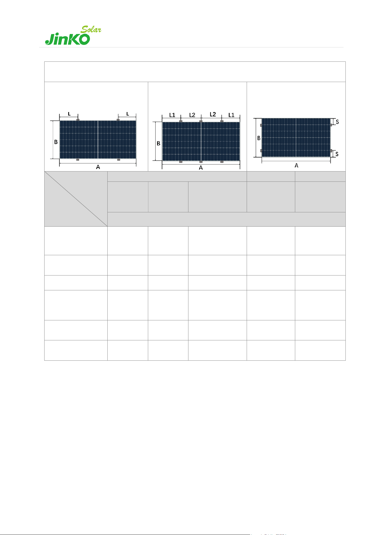
Railless clamping
Method G
Short side clamping (4pcs)
Method H
Long side clamping (6pcs.)
Method I
Short side clamping (4pcs.)
Mounting method
/Range
Module Type
/ Height
Method G
Method H
Method I
L= A/4±50
L=A/5~A/4
L= A/5±50
L1= A/4±50
L2=(A/2-L1)
±50
S=0-100
Maximum test load (Pa)
N-54HL4R-BDB
N-54HL4R-(V)
N-54HL4R-B
/
/
/
/
+1600/-1600
N-54HL4-(V)
/
/
+4200
/-2400
+4800/-2400
+1600/-1600
N-60HL4-(V)
/
/
/
/
+1600/-1600
N-72HL4-(V)
M-72HL4-(V)
(B35)
/
+2400
/-2400
/
/
/
N-72HL4-BDV
M-72HL4-BDVP
+3000
/-2400
/
/
+3600/-2400
+1000/-1000
N-78HL4-BDV
+2800
/-2400
/
/
+3400/-2400
/
Table 7 Maximum test load values for different modules with clamps mounted without rails
15
4.3 Tracker Installation
JinKoSolar modules also have high compatibility with various mainstream tracker systems in the industry. The
maximum test load that JinKoSolar module can achieve is as listed in Table 8 below.
Module type
Tracker system
Installation
Test load (Pa)
N-54HL4-(B)-(V)
ATI V3
Through bolt clamp 1300/1400
mm
+4100/-3200
N-72HL4-(V)
NEXTracker 1P
400 mm hole distance
±2400
N-78HL4-(V)
NEXTracker 1P
400 mm hole distance
±1800
M-72HL4-BDVP
N-72HL4-BDV
NEXTracker 1P
400 mm hole distance
±2400
PVH AXONE DUO-
INFINITY
Short rail 91x428x1,
Hole spacing 1086mm
Length fixation 400mm
±1800
ATI V3
Hi-rise clamp 300 mm
±1200
Hi-rise clamp 400 mm
+1500/-1400
Through bolt clamp 1300 mm
bolting at 1100 mm position only
±2400
Through bolt clamp 1400 mm
bolting at 400 mm and 1400 mm
positions
±3300
N-78HL4-BDV
NEXTracker 1P
400 mm hole distance
±1800
PVH AXONE DUO-
INFINITY
Short rail 91x428x1
Hole spacing 1096mm
Length fixation 400mm
±1600
Long rail 29x1228x1.5
Hole spacing 1096mm
Length fixation 400mm and 1200mm
+2100/-2300
ATI V3
Hi-rise clamp 300 mm
±1200
ATI V3
Hi-rise clamp 400 mm
±1200
N-66HL4M-BDV
PVH AXONE DUO-
INFINITY
Short rail 91x428x1
Hole spacing 1092mm
Length fixation 400mm
+1600/-1650
Long rail 29x818x1.5
Hole spacing 1092mm
Length fixation 400mm and 790mm
+1600/-1900
Table 8 Tracker installation methods and related maximum test loads
Avoid installing PV modules above torque tube connector, post heads or any other part of tracker higher than the
torque tube if there is not a certain horizontal distance (recommend 300mm - 500mm) between edge of the module
and any of those tracker parts. The aim of this distance range is to prevent interference between the tracker structure
and the module junction box during tracker rotation, which may cause damage to the junction box and affect module
performance.

16
For detailed installation drawings and installation method, please refer to installation manual of tracker supplier. For
other tracker systems that are not listed in Table 8, please contact Jinko for more information (cs@jinkosolar.com).
5. Electrical Installation
5.1 Electrical property
- For the electrical design, please find the main electrical parameters shown in the datasheet and product label.
- Modules must be installed and connected with the foam tube removed first. JinKoSolar does not guarantee the
safety of the product or the consistency of the technical parameters if the connectors and tools used are not officially
designated by JinKoSolar or are not installed according to specifications.
- Modules can be connected both in series or in parallel,reasonable design is required according to the system
configuration. In any case, string size (quantity of modules that can be connected together, in series/parallel) must
be calculated taking into consideration local regulations, chosen inverter and project location (environmental
conditions, which may vary from STC). This must be done by qualified professionals.
- When modules are in series, the string voltage is the sum of each module individual voltage. Modules with different
electrical parameters must not be connected in series. String voltage must not be higher than the maximum
permitted system voltage, as well as inverter’s maximum input voltage and other electrical devices that may be
installed in the system. To assure this, we recommend calculating the open circuit voltage of the array at the lowest
expected ambient temperature of the project location, by using the following formula:
𝑀𝑎𝑥. 𝑠𝑦𝑠𝑡𝑒𝑚 𝑣𝑜𝑙𝑡𝑎𝑔𝑒 ≥ 𝑁 ∙ 𝑉
𝑜𝑐
∙
[
1 + 𝑇𝐶
𝑉𝑂𝐶
∙ (𝑇
𝑚𝑖𝑛
− 25)
]
Where:
N
=
Number of modules in series.
V
oc
=
Open circuit voltage (refer to product label or datasheet).
TCvoc
=
Temperature coefficient of open circuit voltage (refer to product label or datasheet).
Tmin
=
Minimum ambient temperature.
- When modules are connected in parallel, the string current is the sum of each module individual current. In this case,
the maximum recommended number of parallel connections is:
𝑁 ≤
𝐹𝑢𝑠𝑒 𝑅𝑎𝑡𝑖𝑛𝑔
𝐼
𝑠𝑐
+ 1
Where:
N
=
Number of maximum parallel connections.
Fuse Rating
=
Maximum fuse rating value in an array string (refer to product label or datasheet).
Isc
=
Short circuit current (refer to product label or datasheet)
- PV modules connected in series shall have similar current, (please contact JinkoSolar if there is any concern), and
modules must not be connected together to create a voltage higher than the permitted system voltage stated in the
label of the module. The maximum number of modules in series depends on system design and the rating of the
17
inverter used.
- The maximum current rating of the module array is identified on the product nameplate or in the product
specification, and the current rating also relates to the maximum reverse current that can be applied to a single
module. For example, when a module is shaded, other modules connected to it will form a load causing a current
loop. Depending on the maximum fuse current rating of the modules and the local electrical installation standards,
the connection of parallel strings of modules needs to be fitted with suitable fuse protection for circuit protection
reasons.
- Open the combiner box of the control system and connect the conductor from the PV arrays to the combiner box in
accordance with the design and local codes and standards. The cross-sectional area and cable connector capacity
must satisfy the maximum short-circuit of the PV system (for a single module, it is recommended that the cross-
sectional area of cables be 4mm² and certified to IEC 62930 type 131), otherwise cables and connectors will become
overheating for large current. Please pay attention that the temperature limit of cables is 90℃.
- Jinko modules junction boxes contain factory-installed bypass diodes. These diodes are connected in parallel with
each cell string to allow the current flow to the next cell array in case there are hot spots or partial shadows in any
of the other cells' string. This will avoid performance and heating losses.
- If modules are incorrectly connected to each other, the bypass diodes, cables or junction boxes may be damaged.
- Keep in mind that bypass diode is not an over-current protection.
- Please do not try to open module junction boxes by yourself.
- Bypass diodes from different manufacturers should not be mated together. If such a replacement is needed,
please contact JinKoSolar.
- For floating projects, please contact local technical support.
5.2 Wiring and cables
- The wiring and cable management should be designed, reviewed and approved by the EPC contractor, especially for
assemblies using tracking brackets. The required cable lengths should be checked in advance, to ensure good
functionality and proper installation.
- The wiring should be checked for correctness before starting the system. If the measured open-circuit voltage (Voc)
and short-circuit current (Isc) do not match the specifications provided, there may be a wiring fault.
- Each string should be left open-circuit until the system is connected to the grid after the modules have been installed.
Appropriate protection is required to avoid the ingress of water vapour and dust.
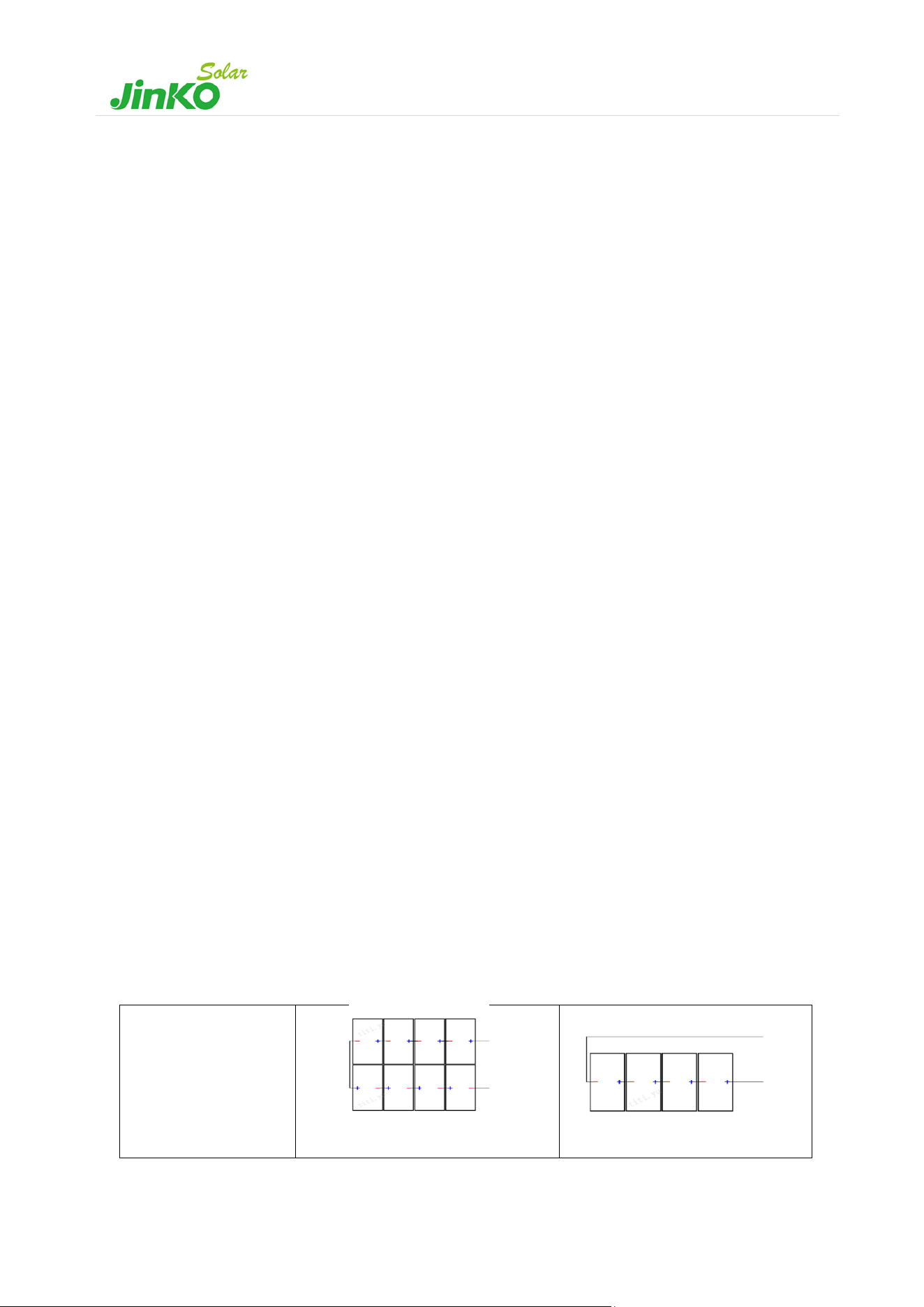
- JinkoSolar recommends the following wiring methods (see Table 9).
Vertical mounting:
Select standard
cables
Dual-row module wiring schematic
Single-row module wiring schematic
18
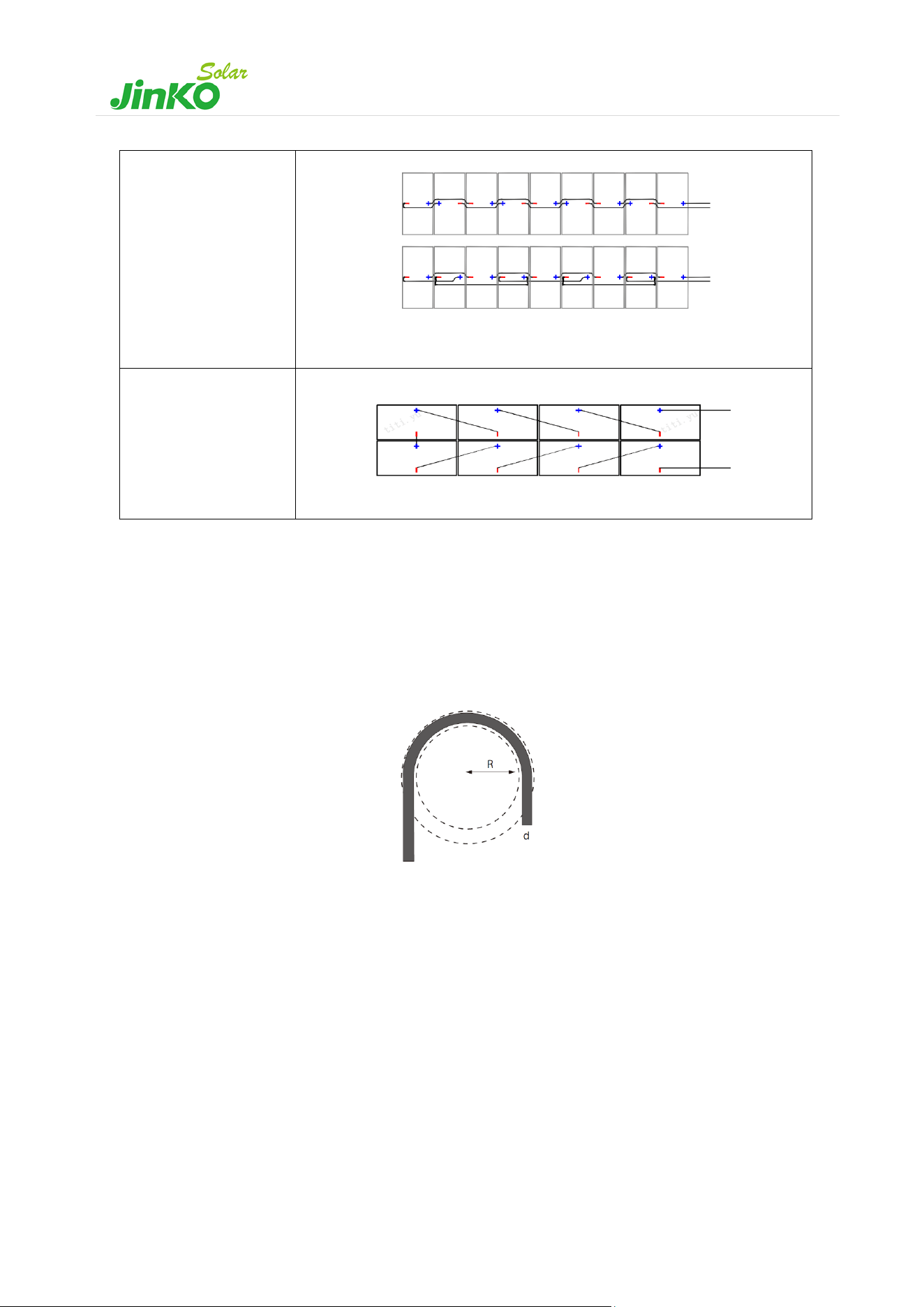
Vertical mounting:
Custom length
cables
Leapfrog wiring
Horizontal mounting:
Custom length
cables
Module wiring schematic
Table 9 Module wiring schematic
(Note: the exact number of series connections will be determined according to the actual design)
- When wiring modules, always keep in mind the minimum bend radius (see Figure 7). This minimum bend radius is
the permissible curvature the cable can be bent around. Depending on the type of cable, a specific coefficient (Cable
multiplier), must be applied. For our DC cables this parameter is 4.
𝑀𝑖𝑛𝑖𝑚𝑢𝑚 𝐵𝑒𝑛𝑑 𝑅𝑎𝑑𝑖𝑢𝑠
(
𝑅
)
= 𝐶𝑎𝑏𝑙𝑒 𝑂𝑢𝑡𝑒𝑟 𝐷𝑖𝑎𝑚𝑒𝑡𝑒𝑟
(
𝑑
)
∙ 𝐶𝑎𝑏𝑙𝑒 𝑀𝑢𝑙𝑡𝑖𝑝𝑙𝑖𝑒𝑟
- Jinko does not guarantee the safety of products and technical parameters consistency if the connecting heads and
tools used are not officially specified by Jinko or are not installed according to the official requirements.
- Before the commissioning and operation of the power station, verify the electrical connection of modules and strings,
ensuring all connections and polarities are correct, and the open circuit voltage meets the requirements of the
acceptance criteria. Incorrect connections may lead to electric arc and electric shock. Please always check that all
electric connections are reliable and that all connectors are fully locked.
- Open the combiner box of the control system and connect the conductor from the PV arrays to the combiner box in
accordance with the design and local codes and standards.
- Three split junction boxes (see in Figure 8) with IP68 installed in Jinko modules provide the necessary safety
protection for cable and wiring connections, including contact protection of non-insulating electric parts.
Figure 7 Minimum Bend Radius
19
- The length of each junction box is given at the component specifications.
Figure 8 The half-cut cell module/split junction box
5.3 Grounding
- For safety reasons and to protect modules from lightning and electrostatic damage, the module frame must be
grounded. The grounding design and the materials used should be in accordance with local national, regional or
international regulations, codes, laws and standards, and the grounding connection should be carried out by
qualified electricians.
- The grounding device must penetrate the anodic oxide film of the component frame and make full contact with the
interior of the aluminium alloy, and the grounding conductor must be connected to earth ground through a suitable
grounding electrode.
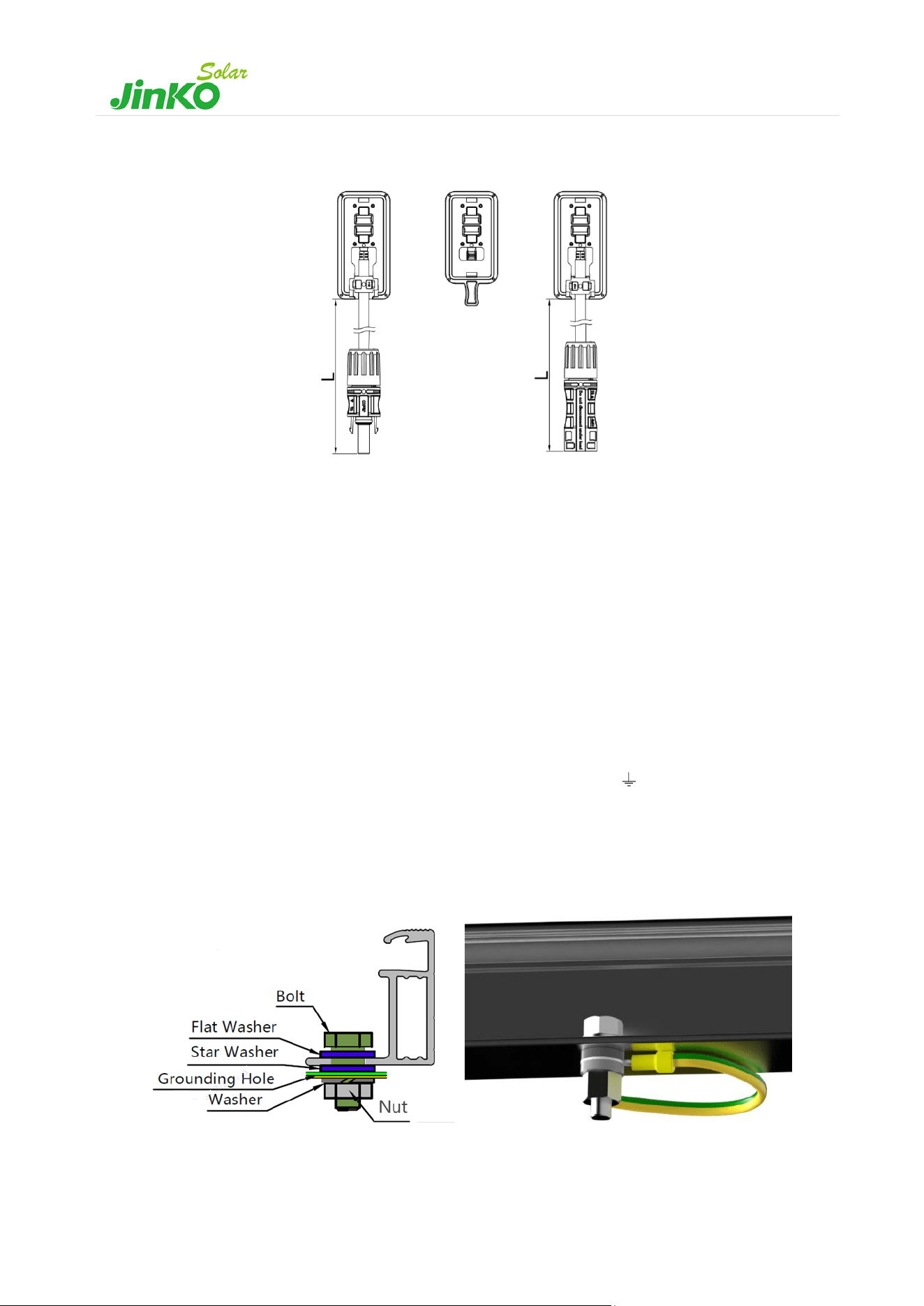
- There are grounding holes with a diameter of 4mm on the long side of the back frame of the module, by the edge
part. The grounding hole on the frame is marked with typical grounding symbol ( ) according to IEC 61730-1:2023
standard. These holes can only be used for grounding with bolts, so cannot be used for module installation. This
method includes bolt, flat washer, start washer, washer and nut(see Figure 9). The bolts should be tightened when
grounding is installed. The frame of the module must not be punched with additional holes and no damage should
be done to the module frame or the grounding wire.
Figure 9. Grounding hole with bolts

20
- Grounding devices and materials must be provided by qualified manufacturers. Bolts, nuts and washers shall be of a
size to match the grounding hole and made of stainless steel, and grounding wires shall be made of copper core
wires with a size of AWG 6-12 (4-14 mm²) and 90°C,and shall be in accordance with relevant local national, regional
or international regulations, laws and standards.
- JinKoSolar allows other grounding methods. However, the following requirements need to be met:
a) It is the sole responsibility of the Installer to select the correct grounding system.
b) Said grounding system must comply with the corresponding electrical codes.
c) JinKoSolar modules must be properly grounded.
d) The chosen grounding methodology does not affect the JinKoSolar Power and Product Warranty in any way.
e) JinKoSolar is not responsible for any failure or defect caused by the selected grounding methodology.
6. Maintenance and care
It is required to perform regular inspection and maintenance of the modules especially during the warranty period.
Please for details, kindly O&M manual. To ensure optimum module performance, JinKoSolar recommends the following
maintenance measures:
6.1 Visual Inspection
Inspect the modules visually to find if there are any visual defects, if there are, the following items should be evaluated:
a) If the modules are observed having slight module color differences at different angles, this is a normal
phenomenon for modules with anti-reflection coating technology. If the colors are within the cell, please
consult JinKoSolar for further analysis.
b) Whether the glass is broken.
c) No sharp objects are in contact with the PV module surfaces.
d) The PV modules are not shaded by unwanted obstacles or foreign material.
e) Corrosion along the cells' busbar. The corrosion is caused by moisture intrusion thought the module rear
side of the module. Check the rear side of the module for damage.
f) Check whether the back sheet is burnt.
g) Check if screws and mounting accessories are tight, adjust and tighten as necessary.
6.2 Cleaning
- A buildup of dust or dirt on the module front face will result in a decreased energy output. Clean the module
preferably once per annum, more frequently in dusty conditions, using soft cloth dry or damp. Water with high
mineral content may leave deposits on the glass surface and is not recommended. It is recommended to use neutral
water of the PH value ranging from 6.5 to 8 to clean the glass, so as not to cause damage to the glass coating layer.
- Never use abrasive material under any circumstances.
- In order to reduce the potential for electrical and thermal shock, JinKoSolar recommends to clean PV modules during

21
early morning or late afternoon hours when solar irradiation is low and the modules are cooler, especially in regions
with hot temperatures.
- Never attempt to clean PV module with broken glass or other signs of exposed wiring, as this presents a shock
hazard.
- Never use chemicals when cleaning modules as this may affect the module warranty and energy yield. For the
environment with extreme climate, please contact JinKoSolar after-sales department for specific requirement if
needed.
- For single-side module, backsheet cleaning is not necessary; for dual-glass module, cleaning the module backside
regularly when necessary, and follow the requirements in 6.1 a) – e). Please wear insulated gloves and pay special
attention to the cables and electrical connections during the backside cleaning.
- If a water gun is used to flush the modules, be careful of the water pressure to avoid damaging the modules.
- If using a hose or backpack style pressure set we recommend the pressure of the water should be less than 675kPa.
6.3 Inspection of Connectors and Cables
It is recommended to implement the following preventive maintenance every 6 months:
- Check the sealing gels of the junction box for any damage.
- Examine the modules for signs of deterioration. Check all wiring for possible rodent damage, weathering and that
all connections are tight and corrosion free. Check the electrical grounding.

22
Global Sales & Marketing Center
No.1, Lane 1466, Shenchang Road,
Minhang District, Shanghai, China
Postcode: 201106
Tel: +86 21 5183 8777
Fax: +86 21 5180 8600
Jiangxi Manufacturing Base
No.1 Yingbin Avenue
Economic Development Zone,
Jiangxi Province, China
Postcode: 334100
Tel: +86 793 858 8188
Fax: +86 793 846 1152
Zhejiang Manufacturing Base
No.58 Yuanxi Road,
Yuanhua Town Industrial Functional Zone,
Haining City, Zhejiang Province, China
Postcode: 314416
Tel: +86 573 8798 5678
Fax: +86 573 8787 1070
Official website:www.jinkosolar.com
Technical Support: rtms@jinkosolar.com | Pre-sale: Globalpresales@jinkosolar.com | Aftersales: CS0001@jinkosolar.com