
High Performance Event Detecon Server
User Manual

Legal Informaon
©2023 Hangzhou Hikvision Digital Technology Co., Ltd. All rights reserved.
About this Manual
The Manual includes instrucons for using and managing the Product. Pictures, charts, images and
all other informaon hereinaer are for descripon and explanaon only. The informaon
contained in the Manual is subject to change, without noce, due to rmware updates or other
reasons. Please nd the latest version of this Manual at the Hikvision website ( hps://
www.hikvision.com/ ).
Please use this Manual with the guidance and assistance of professionals trained in
supporng the
Product.
Trademarks
and other Hikvision's trademarks and logos are the properes of
Hikvision in various jurisdicons.
Other trademarks and logos menoned are the properes of their respecve owners.
Disclaimer
TO THE MAXIMUM EXTENT PERMITTED BY APPLICABLE LAW, THIS MANUAL AND THE PRODUCT
DESCRIBED, WITH ITS HARDWARE, SOFTWARE AND FIRMWARE, ARE PROVIDED "AS IS" AND "WITH
ALL FAULTS AND ERRORS". HIKVISION MAKES NO WARRANTIES, EXPRESS OR IMPLIED, INCLUDING
WITHOUT LIMITATION, MERCHANTABILITY, SATISFACTORY QUALITY, OR FITNESS FOR A PARTICULAR
PURPOSE. THE USE OF THE PRODUCT BY YOU IS AT YOUR OWN RISK. IN NO EVENT WILL HIKVISION
BE LIABLE TO YOU FOR ANY SPECIAL, CONSEQUENTIAL, INCIDENTAL, OR INDIRECT DAMAGES,
INCLUDING, AMONG OTHERS, DAMAGES FOR LOSS OF BUSINESS PROFITS, BUSINESS
INTERRUPTION, OR LOSS OF DATA, CORRUPTION OF SYSTEMS, OR LOSS OF DOCUMENTATION,
WHETHER BASED ON BREACH OF CONTRACT, TORT (INCLUDING NEGLIGENCE), PRODUCT LIABILITY,
OR OTHERWISE, IN CONNECTION WITH THE USE OF THE PRODUCT, EVEN IF HIKVISION HAS BEEN
ADVISED OF THE POSSIBILITY OF SUCH DAMAGES OR LOSS.
YOU ACKNOWLEDGE THAT THE NATURE OF THE INTERNET PROVIDES FOR INHERENT SECURITY
RISKS, AND HIKVISION SHALL NOT TAKE ANY RESPONSIBILITIES FOR ABNORMAL OPERATION,
PRIVACY LEAKAGE OR OTHER DAMAGES RESULTING FROM CYBER-ATTACK, HACKER ATTACK, VIRUS
INFECTION, OR OTHER INTERNET SECURITY RISKS; HOWEVER, HIKVISION WILL PROVIDE TIMELY
TECHNICAL SUPPORT IF REQUIRED.
YOU AGREE TO USE THIS PRODUCT IN COMPLIANCE WITH ALL APPLICABLE LAWS, AND YOU ARE
SOLELY RESPONSIBLE FOR ENSURING THAT YOUR USE CONFORMS TO THE APPLICABLE LAW.
ESPECIALLY, YOU ARE RESPONSIBLE, FOR USING THIS PRODUCT IN A MANNER THAT DOES NOT
INFRINGE ON THE RIGHTS OF THIRD PARTIES, INCLUDING WITHOUT LIMITATION, RIGHTS OF
PUBLICITY, INTELLECTUAL PROPERTY RIGHTS, OR DATA PROTECTION AND OTHER PRIVACY RIGHTS.
YOU SHALL NOT USE THIS PRODUCT FOR ANY PROHIBITED END-USES, INCLUDING THE
High Performance Event Detecon Server User Manual
i

DEVELOPMENT OR PRODUCTION OF WEAPONS OF MASS DESTRUCTION, THE DEVELOPMENT OR
PRODUCTION OF CHEMICAL OR BIOLOGICAL WEAPONS, ANY ACTIVITIES IN THE CONTEXT RELATED
TO ANY NUCLEAR EXPLOSIVE OR UNSAFE NUCLEAR FUEL-CYCLE, OR IN SUPPORT OF HUMAN
RIGHTS ABUSES.
IN THE EVENT OF ANY CONFLICTS BETWEEN THIS MANUAL AND THE APPLICABLE LAW, THE LATTER
PREVAILS.
High Performance Event Detecon Server User Manual
ii

Regulatory Informaon
FCC Informaon
Please take aenon that changes or modicaon not expressly approved by the party responsible
for compliance could void the user's authority to operate the equipment.
FCC compliance: This equipment has been tested and found to comply with the limits for a Class A
digital device, pursuant to part 15 of the FCC Rules. These limits are designed to provide
reasonable
protecon against harmful interference when the equipment is operated in a
commercial environment. This equipment generates, uses, and can radiate radio frequency energy
and, if not installed and used in accordance with the
instrucon manual, may cause harmful
interference to radio communicaons. Operaon of this equipment in a residenal area is likely to
cause harmful interference in which case the user will be required to correct the interference at his
own expense.
FCC
Condions
This device complies with part 15 of the FCC Rules. Operaon is subject to the following two
condions:
1. This device may not cause harmful interference.
2. This device must accept any interference received, including interference that may cause
undesired
operaon.
EU Conformity Statement
This product and - if applicable - the supplied accessories too are marked with "CE"
and comply therefore with the applicable harmonized European standards listed
under the EMC Direcve 2014/30/EU, the LVD Direcve 2014/35/EU, the RoHS
Direcve 2011/65/EU.
2012/19/EU (WEEE direcve): Products marked with this symbol cannot be
disposed of as unsorted municipal waste in the European Union. For proper
recycling, return this product to your local supplier upon the purchase of
equivalent new equipment, or dispose of it at designated
collecon points. For
more
informaon see: www.recyclethis.info
2006/66/EC (baery direcve): This product contains a baery that cannot be
disposed of as unsorted municipal waste in the European Union. See the product
documentaon for specic baery informaon. The baery is marked with this
symbol, which may include
leering to indicate cadmium (Cd), lead (Pb), or
mercury (Hg). For proper recycling, return the
baery to your supplier or to a
designated
collecon point. For more informaon see: www.recyclethis.info
High Performance Event Detecon Server User Manual
iii

Industry Canada ICES-003 Compliance
This device meets the CAN ICES-3 (A)/NMB-3(A) standards requirements.
High Performance Event Detecon Server User Manual
iv
Symbol Convenons
The symbols that may be found in this document are dened as follows.
Symbol Descripon
Danger
Indicates a hazardous situaon which, if not avoided, will or could
result in death or serious injury.
Cauon
Indicates a potenally hazardous situaon which, if not avoided, could
result in equipment damage, data loss, performance degradaon, or
unexpected results.
Note
Provides addional informaon to emphasize or supplement
important points of the main text.
High Performance Event Detecon Server User Manual
v

Safety Instrucon
Regulatory Informaon
This is a class A product and may cause radio interference in which case the user may be required
to take adequate measures.
Laws and Regulaons
Use of the product must be in strict compliance with the local laws and regulaons. Please shut
down the device in prohibited area.
Power Supply
●
Use of the product must be in strict compliance with the local electrical safety regulaons.
●
Use the power adapter provided by qualied manufacturer. Refer to the product specicaon for
detailed power requirements.
●
It is recommended to provide independent power adapter for each device as adapter overload
may cause over-heang or a re hazard.
●
Make sure that the power has been disconnected before you wire, install, or disassemble the
device in the authorized way according to the
descripon in the manual.
●
To avoid electric shock, DO NOT directly touch exposed contacts and components once the
device is powered up.
●
DO NOT use damaged power supply devices (e.g., cable, power adapter, etc.) to avoid electric
shock,
re hazard, and explosion.
●
DO NOT directly cut the power supply to shut down the device. Please shut down the device
normally and then unplug the power cord to avoid data loss.
●
The socket-outlet shall be installed near the equipment and shall be easily accessible.
●
Make sure the power supply has been disconnected if the power adapter is idle.
●
Connect to earth before
connecng to the power supply.
Transportaon,
Use, and Storage
●
To avoid heat
accumulaon, good venlaon is required for a proper operang environment.
●
Store the device in dry, well-venlated, corrosive-gas-free, no direct sunlight, and no heang
source environment.
●
Avoid re, water, and explosive environment when using the device.
●
Install the device in such a way that lightning strikes can be avoided. Provide a surge suppressor
at the inlet opening of the equipment under special
condions such as the mountain top, iron
tower, and forest.
●
Keep the device away from
magnec interference.
●
Avoid device installaon on vibratory surfaces or places. Failure to comply with this may cause
device damage.
●
DO NOT touch the heat
dissipaon component to avoid burns.
High Performance Event Detecon Server User Manual
vi

●
DO NOT expose the device to extremely hot, cold, or humidity environments. For temperature
and humidity requirements, see device specicaon.
●
No naked ame sources, such as lighted candles, should be placed on the equipment.
●
DO NOT touch the sharp edges or corners.
●
To prevent possible hearing damage, DO NOT listen at high volume levels for long periods.
Maintenance
●
If smoke, odor, or noise arises from the device, immediately turn o the power, unplug the
power cable, and contact the service center.
●
If the device cannot work properly, contact the store you purchased it or the nearest service
center. DO NOT disassemble or modify the device in the unauthorized way (For the problems
caused by unauthorized
modicaon or maintenance, the company shall not take any
responsibility).
●
Keep all packaging aer unpacking them for future use. In case of any failure occurred, you need
to return the device to the factory with the original packaging.
Transportaon without the
original packaging may result in damage to the device and the company shall not take any
responsibility.
Network
●
Please enforce the protecon for the personal informaon and the data security as the device
may be confronted with the network security problems when it is connected to the Internet.
Contact us if network security risks occur.
●
Please understand that you have the responsibility to
congure all the passwords and other
security sengs about the device, and keep your user name and password.
Data
DO NOT disconnect the power during formang, uploading, and downloading. Or les may be
damaged.
High Performance Event Detecon Server User Manual
vii

Contents
Chapter 1 Introducon ............................................................................................................... 1
1.1 Producon Introducon ......................................................................................................... 1
1.2 Key Feature ............................................................................................................................ 1
1.3 System Requirement .............................................................................................................. 1
Chapter 2 Acvaon and Login ................................................................................................... 2
2.1 Acvaon ............................................................................................................................... 2
2.1.1 Default Informaon ...................................................................................................... 2
2.1.2 Acvate via SADP .......................................................................................................... 2
2.1.3
Acvate via Web Browser ............................................................................................. 3
2.2 Login ...................................................................................................................................... 4
Chapter 3 Basic Operaon .......................................................................................................... 5
3.1 Set LAN IP Address ................................................................................................................. 5
3.2 Add IP Camera ....................................................................................................................... 6
Chapter 4 Event
Detecon .......................................................................................................... 7
4.1 Set Preset Scene ..................................................................................................................... 7
4.2 Set Camera
Locaon Parameters ........................................................................................... 7
4.3 Set Scene ................................................................................................................................ 9
4.4 Set
Violaon Event ............................................................................................................... 10
4.5 Set Evidence Code ................................................................................................................ 13
4.6 Set Picture Composion ...................................................................................................... 13
4.7 Set Text Overlay ................................................................................................................... 14
4.8 Set Event Record .................................................................................................................. 16
4.9 Set Scene Patrol ................................................................................................................... 16
4.10 Draw Line and Area ............................................................................................................ 18
4.10.1 Draw Lane Line .......................................................................................................... 18
4.10.2 Draw Flow Triggering Line ......................................................................................... 19
High Performance Event Detecon Server User Manual
viii

4.10.3 Draw Rule Area ......................................................................................................... 19
4.10.4 Draw Shielded Area ................................................................................................... 19
4.10.5 Draw Longitude and
Latude Calibraon Area ......................................................... 20
Chapter 5 Data Management .................................................................................................... 21
5.1 Search Data .......................................................................................................................... 21
5.2 Set Upload Data Type ........................................................................................................... 21
5.3 Back up Data ........................................................................................................................ 21
Chapter 6 Storage ..................................................................................................................... 23
6.1 Set Storage Path ................................................................................................................... 23
6.1.1 Format Disk ................................................................................................................. 23
6.1.2 Set FTP ........................................................................................................................ 23
6.1.3 Set SDK Listening ......................................................................................................... 24
6.1.4 Set Cloud Storage ........................................................................................................ 25
6.2 Set Capture Interval ............................................................................................................. 26
Chapter 7 Network ................................................................................................................... 27
7.1 Set Remote Host .................................................................................................................. 27
7.2 Set Port ................................................................................................................................ 27
Chapter 8 Live View and Manual Evidence Capture ................................................................... 28
8.1 Live View .............................................................................................................................. 28
8.2 Set Manual Evidence Capture Parameters ........................................................................... 28
8.3 Capture Picture .................................................................................................................... 29
Chapter 9 Safety Management ................................................................................................. 30
9.1 Manage User ........................................................................................................................ 30
9.2 Set SSH ................................................................................................................................. 30
Chapter 10 Maintenance .......................................................................................................... 31
10.1 Synchronize Time ............................................................................................................... 31
10.2 Synchronize Camera Time .................................................................................................. 31
10.3 Set DST ............................................................................................................................... 32
High Performance Event Detecon Server User Manual
ix

10.4 View Device Informaon .................................................................................................... 32
10.5 Search Log .......................................................................................................................... 32
10.6 Reboot ............................................................................................................................... 32
10.7 Upgrade ............................................................................................................................. 33
10.8 Restore Parameters ............................................................................................................ 33
10.9 Export Parameters ............................................................................................................. 33
10.10 Import Parameters ........................................................................................................... 34
10.11 Set Reserved Parameters ................................................................................................. 34
10.12 Set UID Indicator .............................................................................................................. 34
10.13 Export Debug Log ............................................................................................................. 34
Appendix A.
Communicaon Matrix and Device Command ...................................................... 36
High Performance Event Detecon Server User Manual
x

Chapter 1 Introducon
1.1 Producon Introducon
Event detecon server, the mulple-channel video analysis device, provides mulple funcons,
including real-me smart detecon of events and trac parameters collecon. It can capture the
detected events, and recognize license plates. It is widely applied in cies, highways, tunnels, etc.
1.2 Key Feature
●
Box cameras and speed domes are connectable to detect
trac events and collect trac
parameters.
●
Rack-mounted 1U chassis design, convenient to be placed in the cabinet of machine room.
●
Supports
mulple events detecon, such as congeson, parking, wrong-way driving, etc.
●
Supports
mulple trac parameters collecon, such as vehicle type, lane ow, speed, space
headway,
me headway, etc.
●
Supports zooming capture of illegal parking and patrol detecon of mulple scenes when a
speed dome is connected.
●
Supports
operaon via web browser.
●
Supports customizing specic events detecon.
Note
The supported funcons vary with device models. The actual device prevails.
1.3 System Requirement
●
Web Browser: IE 9.0 and above versions.
●
Resoluon: 1024 × 768 and above.
High Performance Event Detecon Server User Manual
1

Chapter 2 Acvaon and Login
2.1 Acvaon
For the rst-me access, you need to acvate the device by seng an admin password. No
operaon is allowed before acvaon. The device supports mulple acvaon methods, such as
acvaon via SADP soware, web browser, and iVMS-4200 Client.
Note
Refer to the user manual of iVMS-4200 Client for the acvaon via client soware.
2.1.1 Default Informaon
The device default informaon is shown as below.
●
Default IP address: 192.168.1.64
●
Default user name: admin
2.1.2
Acvate via SADP
SADP is a tool to detect, acvate, and modify the IP address of the device over the LAN.
Before You Start
●
Get the SADP soware from the supplied disk or the ocial website ( hp://
www.hikvision.com/ ), and install it according to the prompts.
●
The device and the computer that runs the SADP tool should belong to the same network
segment.
The following steps show how to
acvate one device and modify its IP address. For batch acvaon
and IP address modicaon, refer to User Manual of SADP for details.
Steps
1.
Run the SADP soware and search the online devices.
2.
Find and select your device in online device list.
3.
Enter a new password (admin password) and
conrm the password.
Cauon
STRONG PASSWORD RECOMMENDED-We highly recommend you create a strong password of
your own choosing (using a minimum of 8 characters, including upper case leers, lower case
leers, numbers, and special characters) in order to increase the security of your product. And
we recommend you reset your password regularly, especially in the high security system,
reseng the password monthly or weekly can beer protect your product.
4.
Click Acvate to start acvaon.
High Performance Event Detecon Server User Manual
2
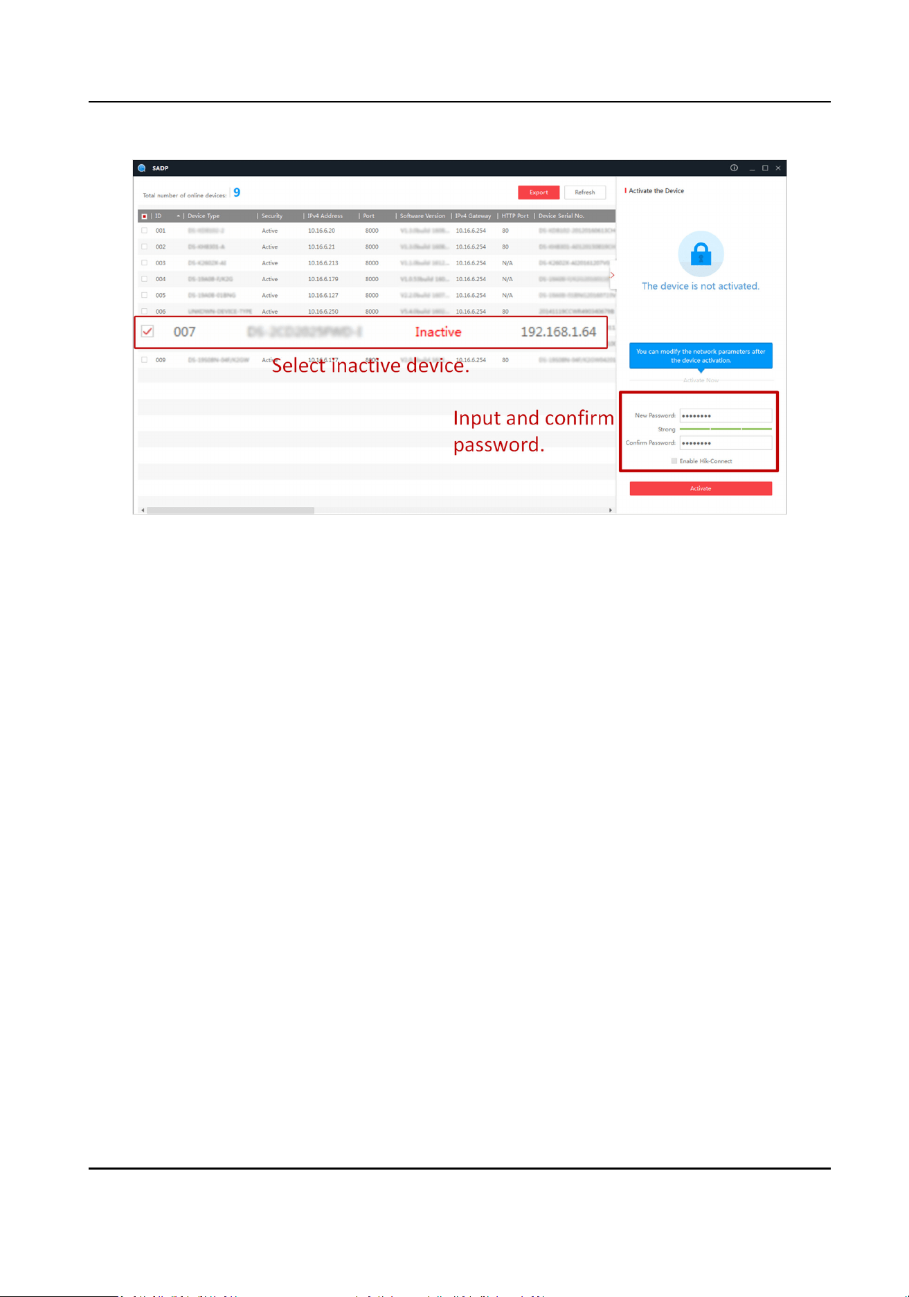
Figure 2-1 Acvate via SADP
Status of the device becomes Acve aer successful acvaon.
5.
Modify IP address of the device.
1) Select the device.
2) Change the device IP address to the same network segment as your computer by either
modifying the IP address manually or checking Enable DHCP (Dynamic Host
Conguraon
Protocol).
3) Enter the admin password and click Modify to
acvate your IP address modicaon.
2.1.3
Acvate via Web Browser
Use web browser to acvate the device. For the device with the DHCP enabled by default, use
SADP soware or client soware to acvate the device.
Before You Start
Ensure the device and the computer are in the LAN with the same network segment.
Steps
1.
Change the IP address of your computer to the same network segment as the device.
2.
Open the web browser, and enter the default IP address of the device to enter the
acvaon
interface.
3.
Create and conrm the admin password.
High Performance Event Detecon Server User Manual
3

Cauon
STRONG PASSWORD RECOMMENDED-We highly recommend you create a strong password of
your own choosing (using a minimum of 8 characters, including upper case leers, lower case
leers, numbers, and special characters) in order to increase the security of your product. And
we recommend you reset your password regularly, especially in the high security system,
reseng the password monthly or weekly can beer protect your product.
4.
Click OK to complete acvaon.
5.
Go to the network sengs interface to modify IP address of the device.
2.2 Login
You can log in to the device via web browser for further operaons such as live view and local
conguraon.
Before You Start
Connect the device to the network directly, or via a switch or a router.
Steps
1.
Open the web browser, and enter the IP address of the device to enter the login interface.
2.
Enter User Name and Password.
3.
Click Login.
4.
Download and install appropriate plug-in for your web browser. Follow the
installaon prompts
to install the plug-in.
5.
Reopen the web browser
aer the installaon of the plug-in and repeat steps 1 to 3 to login.
6.
Oponal: Click Logout on the upper right corner of the interface to log out of the device.
High Performance Event Detecon Server User Manual
4
Chapter 3 Basic Operaon
3.1 Set LAN IP Address
Dierent LAN interfaces correspond to dierent network segments and informaon transmissions
of dierent funcon modules.
Steps
1.
Go to Network → Local → Conguraon → Network .
2.
Click LAN/LAN1/LAN2 to set network according to the actual needs.
Note
●
LAN is used to access the network and connect to the plaorm. LAN1 and LAN2 are both load
balanced, which are used to connect to a camera and get streams from a device.
●
If you need to access the device via a remote domain name, you should congure the DNS
server.
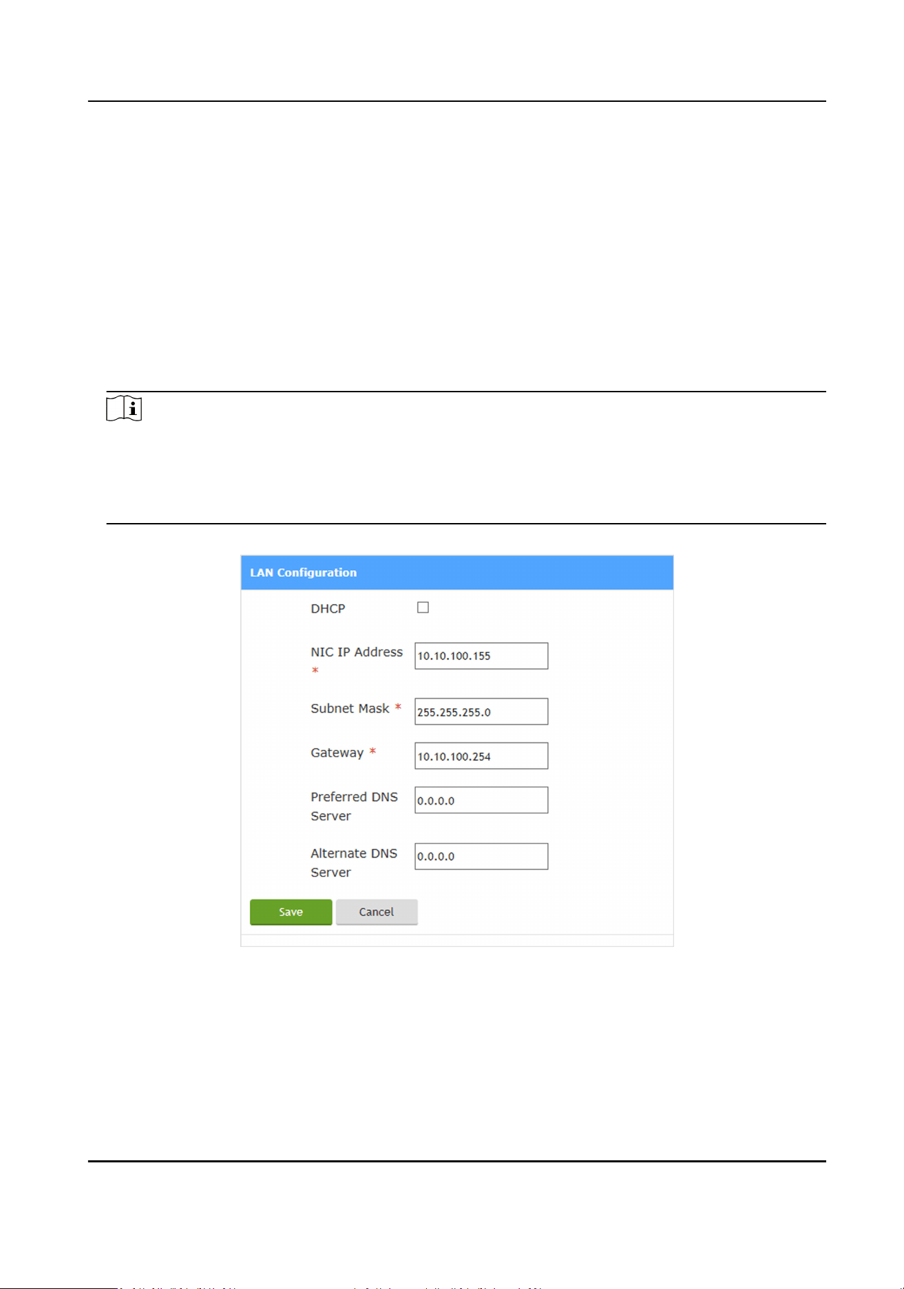
Figure 3-1 LAN Conguraon
-
If the network supports distribung the IP address automacally, you can check DHCP to get
NIC IP Address, Subnet Mask, Gateway, etc. automacally. Click Save and then click OK.
-
Enter corresponding parameters manually, and click Save and then click OK.
3.
Oponal: Go to Network → Local → Conguraon → Basic to view the basic network
informaon.
High Performance Event Detecon Server User Manual
5
3.2 Add IP Camera
Add cameras to the device to facilitate the management and data analysis.
Steps
1.
Click Resources.
2.
Add an IP camera.
Add
quickly
a. Click Add Quickly to automacally get online cameras in a LAN.
b. Check cameras that need to be added.
Note
The user names should be the same for the cameras added in batch. So do
the passwords.
c. Enter User Name and Password.
d. Click Add.
Import in
batch
a. Click Import.
b. Click Export Template, and click OK to save the template in the computer.
c. Edit camera informaon in the template.
Note
You have to edit all the parameters except No. and parent No.
d. Click Browse and select the completed template.
e. Click OK.
Add one
by one
a. Click Add.
b. Select Protocol Type.
c. Enter Device Name, IP Address, Protocol Port, etc.
d. Click Save or Save and Set.
Note
-
Click Save to add the camera to the device.
-
Click Save and Set to add the device and jump to the parameters sengs
interface to set the camera parameters.
3.
Oponal: You can also do the following operaons.
Modify
Check the added camera and click Modify to modify the added camera informaon.
Delete Check the added camera and click Delete to delete the added camera.
Export Click Export to export the camera list.
High Performance Event Detecon Server User Manual
6
Chapter 4 Event Detecon
4.1 Set Preset Scene
The posion informaon such as scenes, focal length, focus, etc. can be saved in the preset scene
to let the PTZ return to a certain scene quickly, convenient for the event detecon in dierent
scenes.
Steps
Note
Only the speed dome supports preset scene conguraon.
1.
Go to Parameters → Scene Conguraon .
Note
Aer entering the interface, the PTZ is locked automacally. During the locked period, only the
current operator can control the PTZ to prevent the other PTZ movement from interfering the
conguraon. Aer the auto lock is released, you can click Lock to lock it again.
2.
Select the speed dome channel and Scene.
3.
Click Preset Scene.
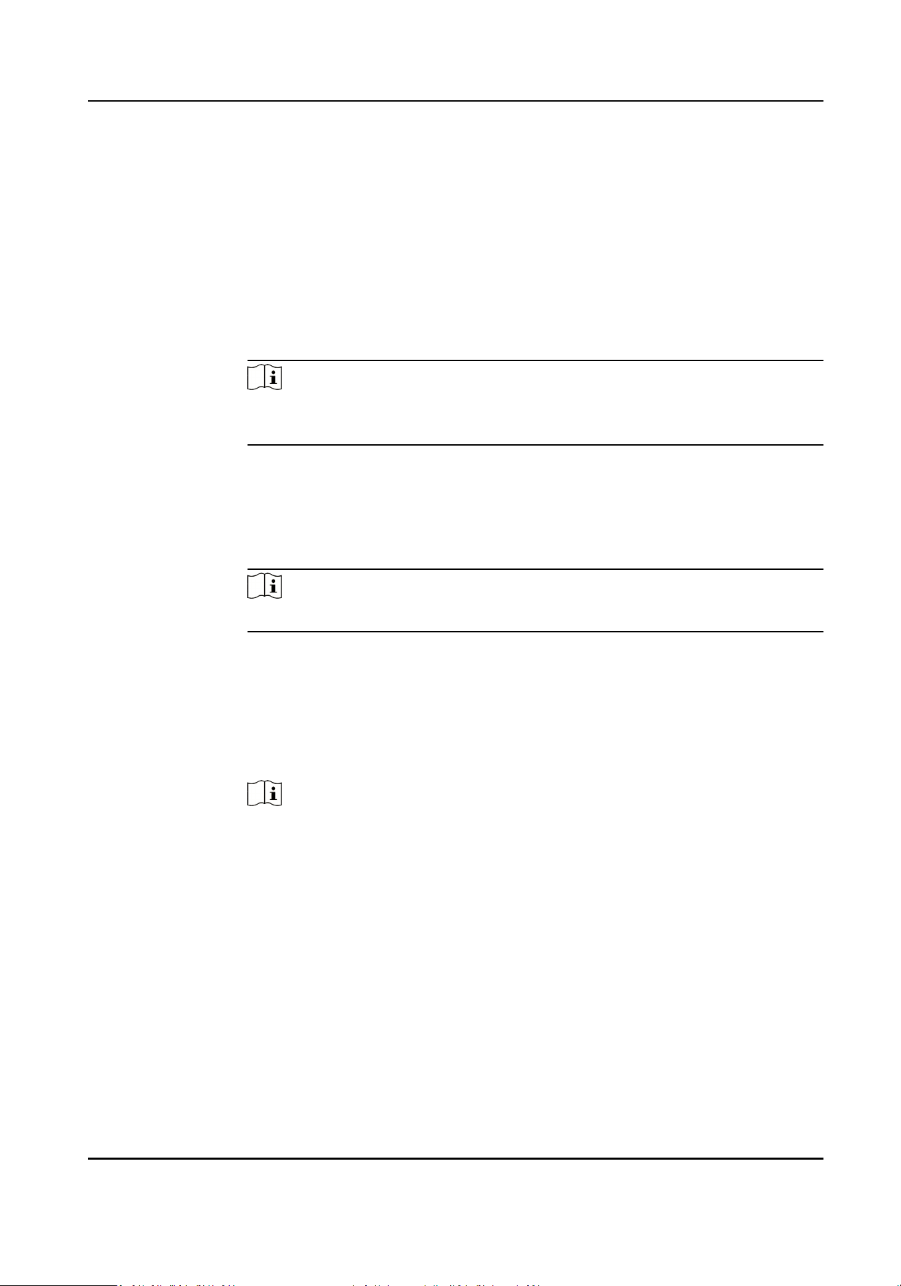
4.
Click the
direcon buons and lens control buons to adjust the live view image to the needed
scene.
Figure 4-1 PTZ Control
5.
Click Set Current Scene to set the current scene as the preset scene.
6.
Oponal: Repeat the steps above to set more preset scenes.
Note
When the device lens deviates from the preset scene, you can click Go to Current Scene to
return to the preset scene quickly.
4.2 Set Camera Locaon Parameters
When you need to capture pictures, set the camera locaon parameters.
High Performance Event Detecon Server User Manual
7
Steps
1.
Go to Parameters → Camera Locaon .
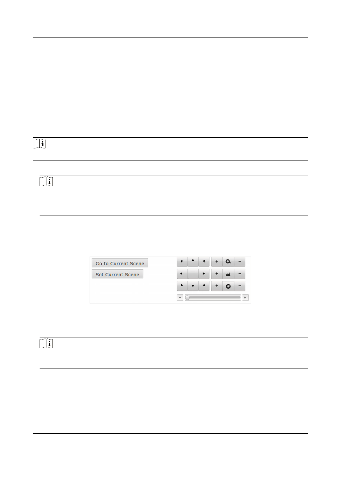
Figure 4-2 Set Camera Locaon Parameters
2.
Select the camera to set.
3.
Set the camera
locaon parameters according to the actual condions.
Direcon
It refers to the driving direcon of the vehicle, depending on which the installaon direcon
of the device lens can be inferred. Upward represents the direcon in which the vehicle is
driving away from the lens. Downward represents the
direcon in which the vehicle is driving
towards the lens.
Note
For the speed dome, go to Parameters → Scene Conguraon → Preset Scene to select the
direcon.
Stream Type
Select the main stream to get the high-quality image when the network condion is good,
and select the sub-stream to get the uent image when the network condion is not good
enough.
Scene Reset Delay
High Performance Event Detecon Server User Manual
8

It refers to the me since the device deviates from the preset scene ll the device returns to
the preset scene to connue the event detecon. Aer the device deviates from the preset
scene, event detecon will stop.
Note
Scene reset delay is only applicable to the speed dome.
Enable POS Recording
Check it to enable POS recording for convenient video collecon for the event detecon
analysis.
Overlay Area Frame
Check it to overlay the area or lane where the corresponding event occurred on the captured
picture.
Rule Informaon
Check it, and the target vehicle and pedestrian will be marked by frames on the live view
image.
Picture Scheduled Capture Interval
Pictures will be captured every set interval.
Short Video
Check it to record the event enforcement process.
Pre-Record
Duraon
The record duraon before the short video starts.
Post-Record Duraon
The record duraon aer the short video ends.
Max. Record Duraon
The max. length of the short video.
Mode Sengs
Select Preset Scene to set the area and lane manually or select Scene Auto-Switch to
automacally set the area and lane.
4.
Oponal: Check the other channel(s) to copy the sengs.
5.
Click Save.
4.3 Set Scene
Set the scene capture parameters.
Before You Start
If the channel is a speed dome, set the preset scene rst.
High Performance Event Detecon Server User Manual
9
Steps
1.
Go to Parameters → Scene Conguraon .
2.
Select the channel and scene.
Note
Scene is only available for the speed dome.
3.
Set the scene name.
1) Click Event Rule.
2) Select Scene Mode according to actual needs.
3) Enter Scene Name.
4) Click Save.
4.
Oponal: For the speed dome channel, set the basic scene parameters.
1) Click Preset Scene.
2) Check Enable This Scene.
3) Select the
direcon according to the actual driving direcon.
4) Oponal: Check the copying mode and the channel(s) to copy the conguraon.
All
Check it to copy the parameters of Event Rule, Preset Scene, and Draw Area.
Copy Event Rule Parameters
Check it to copy the parameters of Event Rule and Preset Scene.
5) Click Save.
4.4 Set
Violaon Event
The device supports mulple violaon events detecon. Aer the event rule conguraon, the
device will detect and capture the events according to the set rules automacally.
Before You Start
Set the scene rst.
Steps
1.
Go to Parameters → Scene Conguraon .
2.
Select the channel and scene.
Note
Scene is only available for the speed dome.
3.
Click Event Rule.
4.
Select Scene Mode.
5.
Enter Scene Name.
6.
Oponal: Check Longitude and Latude Calibraon, and enter the longitudes and latudes of
the four
calibraon area vertexes to calibrate the coordinates.
High Performance Event Detecon Server User Manual
10
Note
The longitudes and latudes informaon can only be uploaded via the SDK protocol. Relevant
parameters need to be set through the path System → Sengs → Basic Conguraon before
uploading.
7.
Check the event(s) to be detected.
Note
●
The supported events vary with dierent scene modes. The actual device prevails.
●
Congeson and Congeson (Area) cannot be enabled at the same me. Select Congeson
when you need to detect the congeson event of the whole road. Select Congeson (Area)
when you need to detect the
congeson event of an area.
8.
Set the event parameters.
Note
The supported parameters vary with dierent models. The actual device prevails.
Long Range Target Frame
When the vehicle with violaon event is far away from the lens, the target frame will appear
on the live view image to mark the vehicle posion.
Duraon
When the vehicle stays at the detecon area or lane line for a me period longer than the set
duraon, the vehicle will be judged as a vehicle with violaon event.
Filtering Time
The violaon capture during the set ltering me will be judged as the violaon capture of
the same target. In this case, only one captured picture will be uploaded.
Linked Congeson Threshold
When the vehicle density in the detecon area or lane line exceeds the set threshold, no
picture will be captured or uploaded.
Sensivity
The higher the sensivity is, the more possible it is for the detecon target to be recognized
as the vehicle with violaon events. If the value is too high, detecon mistakes may occur. If
the value is too low,
detecon loopholes may occur. Therefore, it's recommended that the
value should be set reasonably according to the actual condions.
Capturing Target
Select the capturing target type according to actual needs.
Congeson Upper/Lower Limit
It is used to evaluate the trac ow congeson status. If the vehicle density is higher than
the set upper limit, the
trac ow status is congeson. If the vehicle density falls between
High Performance Event Detecon Server User Manual
11

the set lower limit and the set upper limit, the trac ow status is slow running. If the vehicle
density is lower than the set lower limit, the trac ow status is uent running.
Trac Jam Length
When the low-speed vehicle density exceeds the set value, the current trac condion is
considered as congeson.
Duplicate Alarm Before Cancelling Congeson
Check it to enable repeated alarm data reporng unl the vehicle evacuaon is achieved.
Stascs Time
The camera data stascs and uploading will be done every the set me.
Flow Margin
It refers to the distance from the ow trigger line 1 to ow trigger line 2, which is used to
calculate the average speed.
Alarm in Construcon
Check it to enable trac accident or vehicle failure alarm in construcon events.
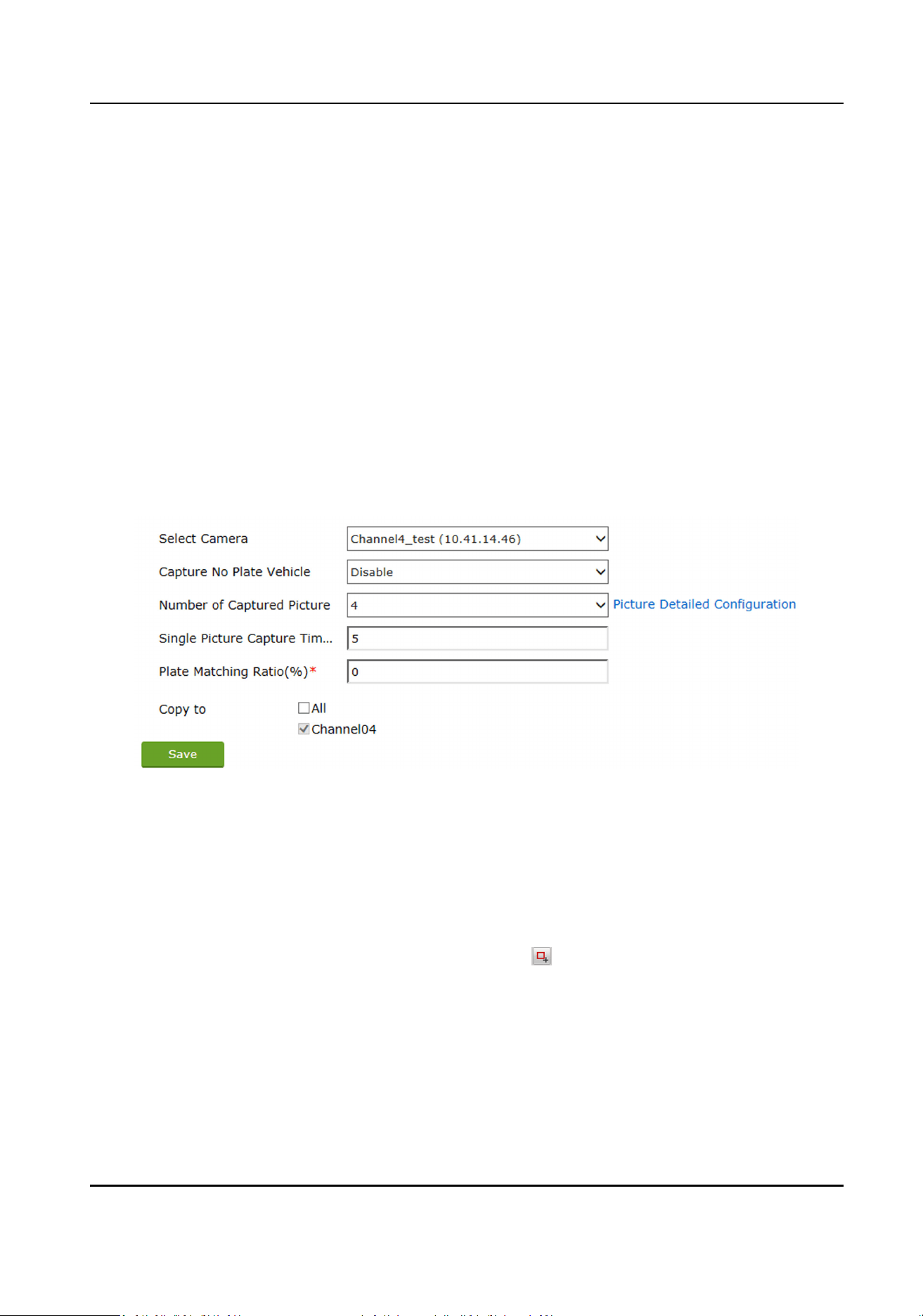
9.
Oponal: If the channel is a speed dome, and the illegal parking event has been enabled, you
can set the illegal parking evidence capture of the current scene.
1) Click Preset Scene.
2) Check Capture No Plate Vehicle when you need to capture the vehicles without license
plates.
Note
The funcon is only available for the captured close view pictures. When you set all the
captured pictures as distant view ones, no maer you check it or not, the vehicles without
license plates will be detected.
3) Set the parameters below.
Number of Captured Picture
The number of the captured pictures for illegal parking
detecon.
Single Picture Capture Timeout
It refers to the max. me of one picture capture. If the me exceeds the value, one picture
of the current scene will be captured as the evidence picture.
Plate Matching Rao
When the plate matching rao of vehicles exceeds the set value, the vehicles with the
license plates will be judged as the same one, and the violaon of the vehicle will only be
captured once.
4) Click Picture Detailed
Conguraon to set the capture interval and picture type.
Capture Interval
The me interval between two captured pictures.
Picture Type
High Performance Event Detecon Server User Manual
12

In order to guarantee the license plate recognion result, set at least one close view
picture.
5) Click Save.
When the illegal parking is detected, the device will capture pictures according to the set picture
No. and interval.
10.
Check Area Linkage or Lane Linkage.
11.
Draw the rule areas or lane lines according to the actual needs.
Operaon Reference
Draw lane lines Draw Lane Line
Draw ow triggering lines Draw Flow Triggering Line
Draw rule area Draw Rule Area
Draw shielded area Draw Shielded Area
Draw calibraon area Draw Longitude and Latude Calibraon Area
12.
Oponal: Check the copying mode and the channel(s) to copy the event rule conguraon.
All
Check it to copy the parameters of Event Rule, Preset Scene, and Draw Area.
Copy Event Rule Parameters
Check it to copy the parameters of Event Rule and Preset Scene.
13.
Click Save.
4.5 Set Evidence Code
Evidence codes dene various violaon types. Through seng evidence codes, dierent captured
evidences can be easily managed.
Steps
1.
Go to System →
Sengs → Evidence Code .
2.
Select the captured evidence(s) according to your needs or edit the captured evidence and the
corresponding evidence code
aer clicking the captured evidence.
3.
Oponal: Click Reset to restore to defaults.
4.6 Set Picture
Composion
You can composite the captured mulple pictures to one picture to upload and store.
Steps
1.
Go to Parameters → Picture Composion .
High Performance Event Detecon Server User Manual
13
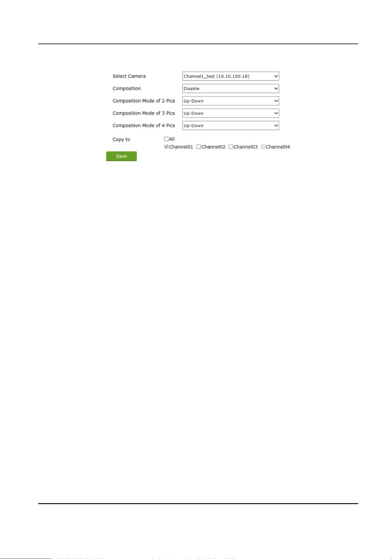
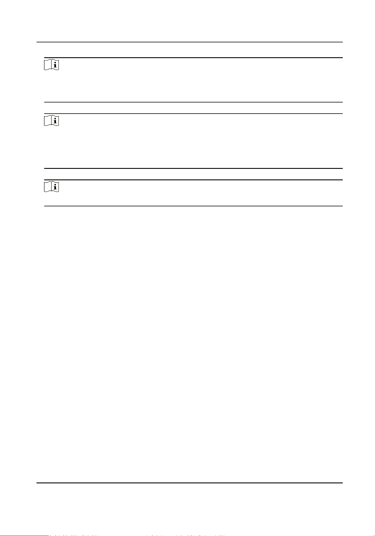
Figure 4-3 Set Picture Composion
2.
Select the channel.
3.
Enable picture composion.
4.
Select the composion mode of two/three/four pictures.
5.
Oponal: Check the channel(s) to set the same sengs.
6.
Click Save.
4.7 Set Text Overlay
You can overlay the informaon such as the intersecon, lane No., license plate number, etc. on
the captured pictures.
Steps
1.
Go to Parameters → Text Overlay .
High Performance Event Detecon Server User Manual
14
Figure 4-4 Set Text Overlay
2.
Select the channel.
3.
Set the text overlay parameters.
Overlay Mode
Overlay on Picture
The text will be overlaid within the picture.
Overlay Above Picture
The text will be overlaid on the top of the picture outside.
Overlay Below Picture
The text will be overlaid on the
boom of the picture outside.
Overlay Line Percentage
It is the percentage that the overlaid informaon occupies on the picture. For example, if you
set the percentage to 50, the overlaid informaon in a row will occupy up to half of the image
width, and the excess content will be overlaid from a new line.
Inial Top Margin
Set the top coordinate from which the text begins to overlay.
Inial Le Margin
Set the le coordinate from which the text begins to overlay.
Spaces Aer Overlay Items
High Performance Event Detecon Server User Manual
15

Set the number of space aer between two overlaid items. For example, if you set it as 1, the
adjacent overlaid items will be separated with one space.
Character Spacing
Set the distance between characters.
Overlay Content
Click the text led to check the overlaid informaon, and click Save.
Note
If the overlaid informaon exceeds the overlay area, the excess content will not be displayed.
4.
Oponal: Check the channel(s) to set the same sengs.
5.
Click Save.
4.8 Set Event Record
The device supports event recording funcon when detecng relevant events.
Steps
1.
Go to Parameters → Camera Locaon .
2.
Check Short Video.
3.
Set recording parameters according to actual needs.
Pre-Record
Duraon
The record duraon before the short video starts.
Post-Record Duraon
The record duraon aer the short video ends.
Max. Record Duraon
The max. length of the short video.
4.
Click Save.
4.9 Set Scene Patrol
You can set the scene patrol schedule to make the device monitor the preset scene in patrol during
the set period.
Before You Start
Only the speed dome supports scene patrol. Ensure at least two preset scenes have been set.
Steps
1.
Go to Parameters → Scene Patrol .
High Performance Event Detecon Server User Manual
16
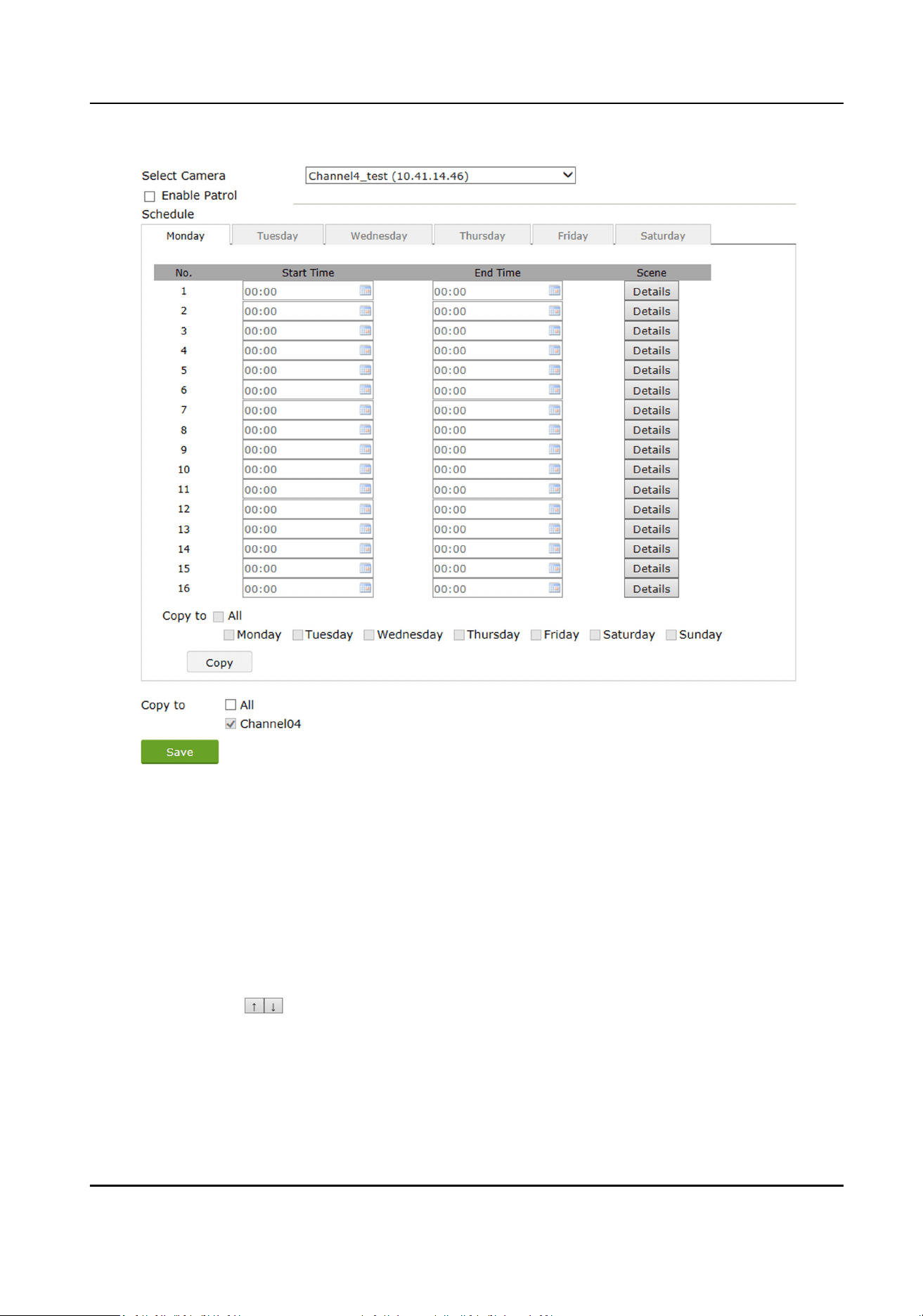
Figure 4-5 Set Scene Patrol
2.
Select the channel.
3.
Check Enable Patrol Schedule.
4.
Select the day to set the schedule.
5.
Set the start and end
me of the period.
6.
Set the scene patrol.
1) Click Details.
2) Click Add New Rule to add the scene.
3) Select Scene and set Dwell Time.
4)
Oponal: Click to adjust the scene sequence.
5) Click OK.
7.
Oponal: Check the channel(s) to set the same sengs.
8.
Click Save.
High Performance Event Detecon Server User Manual
17
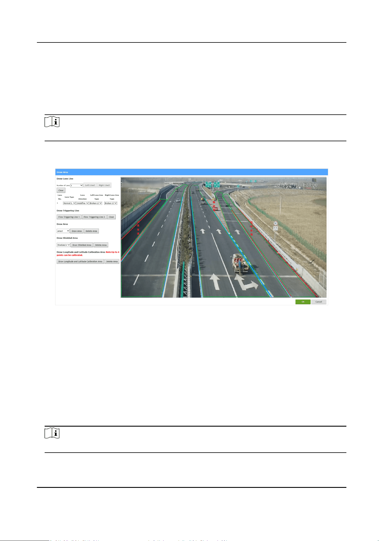
4.10 Draw Line and Area
Steps
1.
Go to Parameters → Scene Conguraon .
2.
Select the channel and scene.
Note
Scene is only available for the speed dome.
3.
Click Event Rule.
4.
Click Draw Area.
Figure 4-6 Draw Line and Area
4.10.1 Draw Lane Line
You need to set lane lines for event detecon. Draw two lane lines for each real lane, and up to six
lanes can be set for each scene.
Steps
1.
Go to Draw Area → Draw Lane Line .
2.
Select Number of Lane.
3.
Click
Le Line and Right Line, and click the le buon of the mouse to locate the two ends of
the line to draw the lane line according to the actual lane locaon.
Note
The adjacent lane areas cannot be overlapped.
4.
Oponal: Click Clear to clear all the lane lines.
High Performance Event Detecon Server User Manual
18
5.
Set the lane parameters such as Lane Type, Lane Direcon, etc.
6.
Click OK.
4.10.2 Draw Flow Triggering Line
Draw ow triggering lines for the congeson or trac ow detecon.
Steps
1.
Go to Draw Area → Draw Triggering Line .
2.
Select the
ow triggering line to draw.
3.
Click the le buon of the mouse to locate the two ends of the line to draw the triggering line at
the locaon needing to detect the trac ow.
Note
The ow triggering line must be crossed with the lane line.
4.
Oponal: Click Clear to clear all the triggering lines.
5.
Click OK.
4.10.3 Draw Rule Area
Draw the rule areas to detect the events in the areas.
Steps
1.
Go to Draw Area → Draw Area .
2.
Select the area to draw.
3.
Click Draw Area.
4.
Click the
le buon of the mouse to draw a rectangular or polygonal frame, and then click the
right buon of the mouse to save the area.
Note
The areas of dierent events can be overlapped.
5.
Oponal: Click Delete Area to delete the current area.
6.
Click OK.
4.10.4 Draw Shielded Area
The shielded area is an area in which the events will not be detected. Interference can be greatly
reduced when the shielded area is drawn.
Steps
1.
Go to Draw Area → Draw Shielded Area .
2.
Select the shielded area to draw.
High Performance Event Detecon Server User Manual
19

3.
Click Draw Shielded Area.
4.
Click the le buon of the mouse to draw a rectangular or polygonal frame, and then click the
right buon of the mouse to save the area.
Note
The shielded areas can be overlapped.
5.
Oponal: Click Delete Area to delete the current area.
6.
Click OK.
4.10.5 Draw Longitude and Latude Calibraon Area
Draw the longitude and latude calibraon area to calibrate the coordinates of the area vertexes.
Before You Start
Enable Longitude and
Latude Calibraon in event rule sengs.
Steps
1.
Go to Draw Area → Draw Longitude and Latude Calibraon Area .
2.
Click Draw Longitude and Latude Calibraon Area.
3.
Click the
le buon of the mouse to draw a rectangular frame, and then click the right buon of
the mouse to save the area.
4.
Oponal: Click Delete Area to delete the current area.
5.
Click OK.
High Performance Event Detecon Server User Manual
20

Chapter 5 Data Management
5.1 Search Data
You can search and export the event detecon and violaon capture data of the connected
cameras, or the trac parameters stascs of the cameras.
Steps
1.
Click Data Search.
2.
Search the event
detecon and violaon capture data.
1) Click Data Search.
2) Set Start Time and End Time.
3) Select Device ID, Data Type, and
Violaon Type.
4) Click Search.
The searched result will be listed on the right.
5)
Oponal: Select the data you want to export, and click Export to export the data to your
computer.
3.
Search the
trac parameters stascs of the cameras.
1) Click Parameters Stascs.
2) Set Start Time and End Time.
3) Select Device ID.
4)
Oponal: Set Lane No.
5) Click Search.
The searched result will be listed on the right.
6)
Oponal: Select the data you want to export, and click Export to export the data to your
computer.
5.2 Set Upload Data Type
The device supports seng upload data type to meet various data uploading needs.
Steps
1.
Go to System → Sengs → Upload Arming Data Type .
2.
Click the input box behind Upload Data Type to check the data type(s) to be uploaded.
3.
Click Save.
5.3 Back up Data
The device supports backing up data to your computer.
High Performance Event Detecon Server User Manual
21

Before You Start
The data search has been made.
Steps
1.
Set the rules for
exporng pictures and videos.
1) Go to System → Sengs → Web Backup .
2) Enter the naming rules and saving paths of the pictures and videos.
3) Click Save.
2.
Add the IP address of this device as the trusted site in the safety
sengs of your browser.
3.
Refer to
Search Data to search data.
4.
Click Export to select the le type(s).
5.
Click OK.
Result
The pictures and videos will be backed up according to the set naming rules in the set saving paths.
High Performance Event Detecon Server User Manual
22
Chapter 6 Storage
6.1 Set Storage Path
6.1.1 Format Disk
Format the disk when the storage is abnormal or a new disk is installed.
Steps
Cauon
Formang the disk will cause the disk data loss. Back up the data rst.
1.
Go to System → Sengs → Format Disk .
2.
Click Format Disk.
3.
Click OK on the popup window.
6.1.2 Set FTP
Set FTP parameters if you want to upload the captured pictures or videos to the FTP server.
Before You Start
Set the FTP server, and ensure the device can communicate normally with the server.
Steps
1.
Go to System → FTP Upload .
High Performance Event Detecon Server User Manual
23
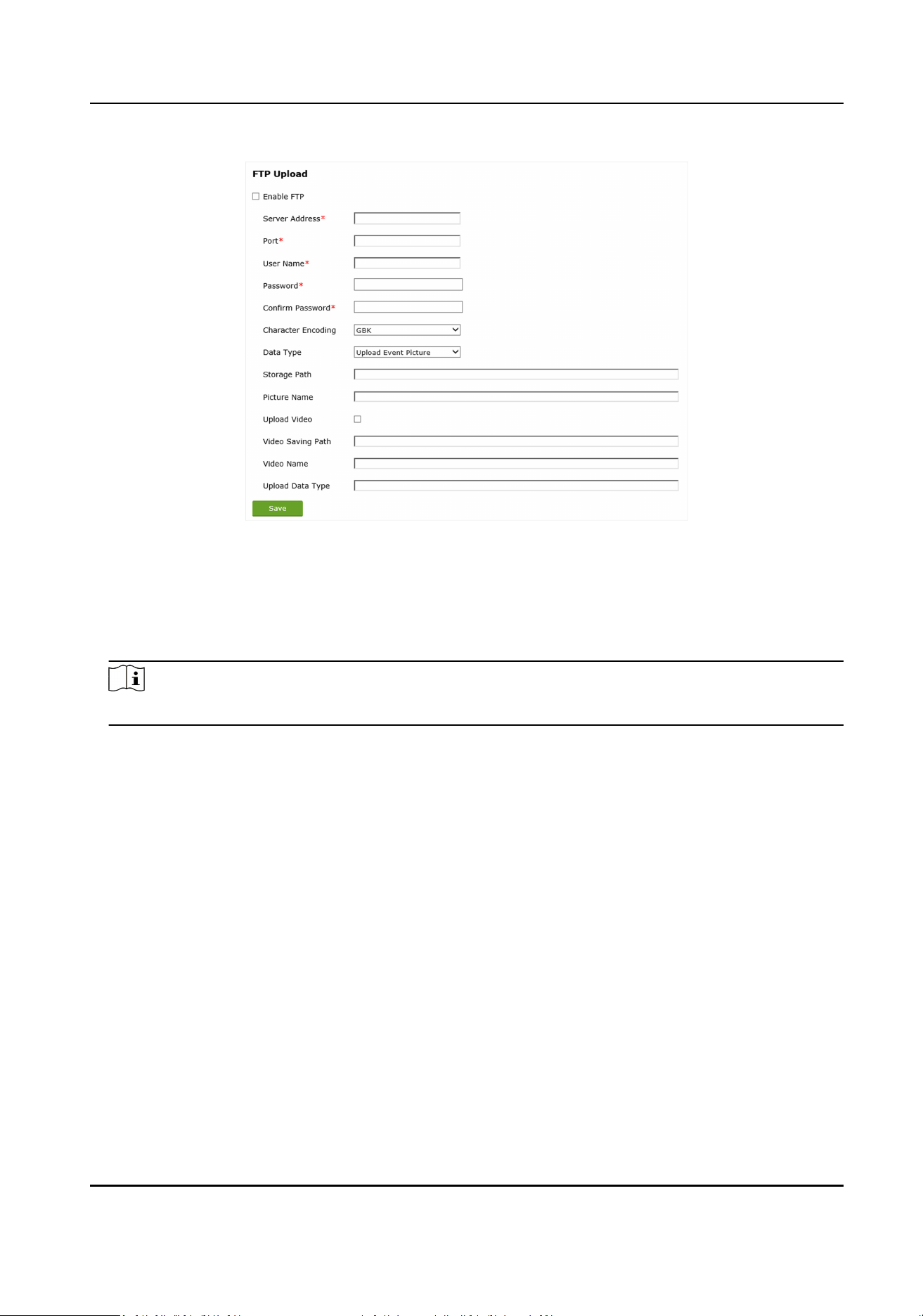
Figure 6-1 Set FTP
2.
Check Enable FTP.
3.
Enter Sever Address, Port, User Name, Password, and
conrm the password.
4.
Set the character encoding format.
5.
Select Data Type.
Note
Some types of devices support uploading one data type only. The actual interface prevails.
6.
Set Storage Path and Picture Name.
7.
Oponal: Upload the event enforcement videos to the FTP server.
1) Check Upload Video.
2) Set Video Saving Path, Video Name, and Upload Data Type.
8.
Click Save.
6.1.3 Set SDK Listening
The SDK listening can be used to receive the arming alarm informaon uploaded by the device.
Before You Start
The listening service has been enabled for the listening host, and the network communicaon
between the listening host and the device is normal.
Steps
1.
Go to System → Sengs → Basic Conguraon → NIC Parameters .
High Performance Event Detecon Server User Manual
24
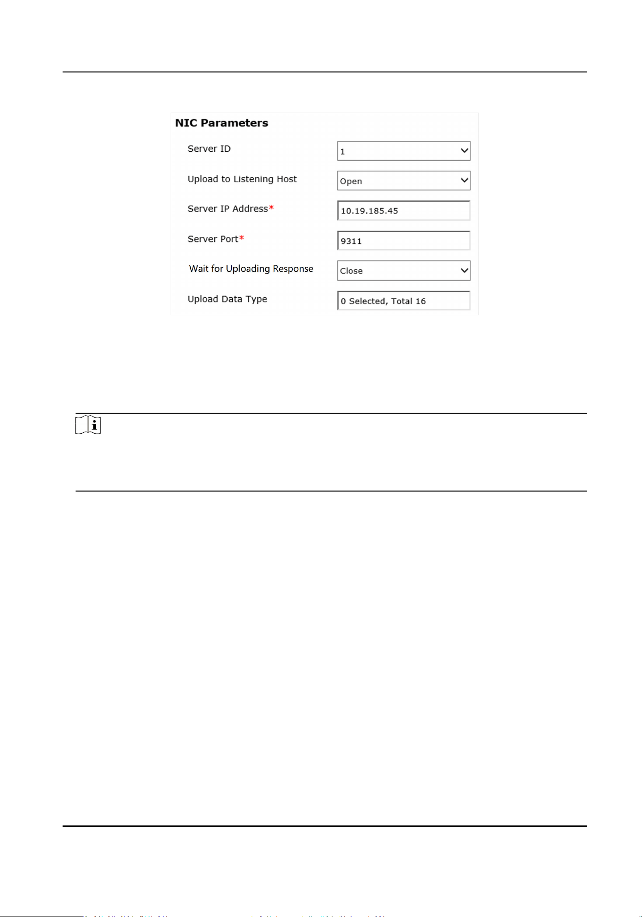
Figure 6-2 Set Listening Host
2.
Select Server ID.
3.
Enable Upload to Listening Host.
4.
Set Server IP Address and Server Port.
5.
Oponal: Enable Wait for Uploading Response.
Note
●
This funcon is for professionals use only.
●
This funcon is only available when the plaorm that receives the data supports uploading
response.
The plaorm will send a response to the device aer receiving the uploaded data from the
device. If the device does not receive the response from the plaorm, it means that uploading
failed.
6.
Click the input box behind Upload Data Type to check the data type(s) to be uploaded.
7.
Click Save.
6.1.4 Set Cloud Storage
Cloud storage is a kind of network storage. It can be used as the extended storage to save the
captured pictures.
Before You Start
Arrange the cloud storage server.
Steps
1.
Go to System → Basic
Conguraon → Cloud Storage .
2.
Check Cloud Storage.
3.
Set the server parameters.
High Performance Event Detecon Server User Manual
25

1) Enter Server IP Address, Port No., and other parameters.
2) Enter accessKey and secretKey.
4.
Click Save.
6.2 Set Capture Interval
Set capture interval to enable picture capturing at a set me interval.
Steps
1.
Go to Parameters → Camera Locaon .
2.
Set Picture Scheduled Capture Interval according to the actual needs.
3.
Click Save.
High Performance Event Detecon Server User Manual
26

Chapter 7 Network
7.1 Set Remote Host
Set remote host when the device needs to transmit data to the central control plaorm.
Before You Start
Set the remote host, and ensure the device can communicate normally with the remote host.
Steps
1.
Go to System → Sengs → Remote Host .
2.
Select Upload Protocol.
HTTP
The device communicates with the remote host via HTTP.
3.
Enable Upload.
4.
Set URL, Address Type, IP Address, and Port of the remote host.
5.
Select Data Type.
6.
Click the input box behind Upload Data Type to select the data type(s) to be uploaded.
7.
Click Save.
7.2 Set Port
The device port can be modied when the device cannot access the network due to port conicts.
Steps
1.
Go to System →
Sengs → Basic Conguraon → Port .
2.
Set SDK Port according to the actual needs.
3.
Click Save.
High Performance Event Detecon Server User Manual
27
Chapter 8 Live View and Manual Evidence Capture
8.1 Live View
Click Live View, and double click the channel in the channel list to start live view.
8.2 Set Manual Evidence Capture Parameters
For the speed dome, you can set the manual evidence capture parameters. Then when you capture
the evidence pictures on the live view interface, the device will capture pictures according to the
set rules.
Steps
1.
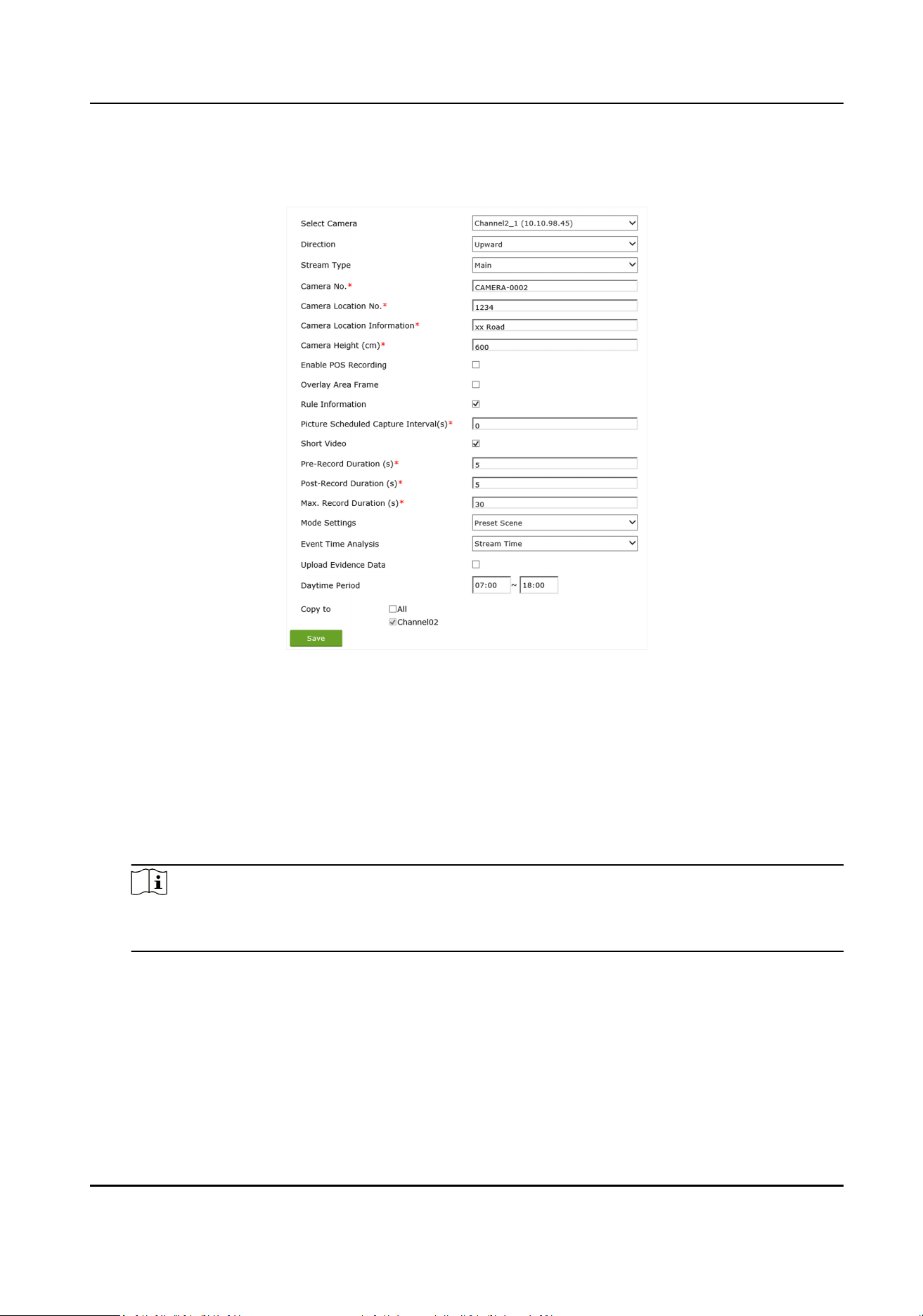
Go to Parameters → Manual Evidence Capture .
Figure 8-1 Set Manual Evidence Capture Parameters
2.
Select the channel.
3.
Set the parameters below.
Capture No Plate Vehicle
If you enable the
funcon, the vehicles without license plates will be captured.
Number of Captured Picture
The number of the captured pictures when you click on the live view interface.
Single Picture Capture Timeout
When the capture and uploading me of one picture exceeds the set me, a new picture will
be captured and uploaded.
Plate Matching
Rao
When the plate matching rao exceeds the set value, the vehicles with the license plates will
be judged as the same one, and the events of the vehicle will only be captured once.
High Performance Event Detecon Server User Manual
28
4.
Click Picture Detailed Conguraon to set the capture interval and picture type.
Capture Interval
The me interval between two captured pictures.
Picture Type
In order to guarantee the license plate recognion result, set at least one close-up picture.
5.
Oponal: Check the channel(s) to set the same sengs.
6.
Click Save.
8.3 Capture Picture
Note
Only the speed dome supports manual capture.
Click Live View. Click , and the device will capture pictures.
High Performance Event Detecon Server User Manual
29
Chapter 9 Safety Management
9.1 Manage User
The administrator can add, modify, or delete other accounts, and grant dierent permissions to
dierent user levels.
Before You Start
Set the administrator password when you rst use the device to ensure a normal working.
Steps
1.
Go to System →
Sengs → User Conguraon .
2.
Add a user.
1) Click Add.
2) Enter User Name, Password, and
conrm the password.
Cauon
To increase security of using the device on the network, please change the password of your
account regularly. Changing the password every 3 months is recommended. If the device is
used in high-risk environment, it is recommended that the password should be changed every
month or week.
3) Click Save.
3.
Oponal: Click the user name of the added user to edit the user informaon.
4.
Oponal: Select a user and click Delete to delete the user.
9.2 Set SSH
To improve network security, it is recommended to disable the SSH service. The service is
especially saved for the professionals to debug the device.
Steps
1.
Go to System →
Sengs → Security Service .
2.
Check Enable SSH.
3.
Set SSH Port.
4.
Click Save.
High Performance Event Detecon Server User Manual
30
Chapter 10 Maintenance
10.1 Synchronize Time
Synchronize the device me when it is inconsistent with the actual me.
Steps
1.
Go to System → Sengs → Time Conguraon .
2.
Select the me synchronizaon mode.
-
If an NTP server is available, select NTP and enter NTP server informaon to synchronize the
device me with that of the NTP server.
-
Select Manual Time Sync. and set
me to customize the device me.
-
Select Manual Time Sync. and check Sync. with computer me to synchronize the device
me with that of the computer.
3.
Click Save.
Note
The me synchronizaon modes vary with dierent models. The actual device prevails.
10.2 Synchronize Camera Time
It is recommended to synchronize the camera me when the camera me is inconsistent with the
device
me.
Steps
Note
The sengs are only applicable to SDK protocol cameras.
1.
Go to System → Sengs → Camera Time Sync.
2.
Check Enable Camera Time Sync.
3.
Set Interval.
4.
Click Save.
Result
The device will synchronize the camera me at the set interval to ensure its me is consistent with
the device
me.
High Performance Event Detecon Server User Manual
31

10.3 Set DST
If the region where the device is located adopts Daylight Saving Time (DST), you can set this
funcon.
Steps
1.
Go to System → Sengs → DST .
2.
Check Enable DST.
3.
Set Start Time, End Time, and Bias Time.
4.
Click Save.
10.4 View Device
Informaon
View Device Basic Informaon
Go to System → Version to view device versions and plugin informaon.
View Device Performance
Go to Network → Local → Performance to view CPU Usage Rate, Network IO, and Temperature.
View System Status
Go to System → Sengs → System Status to view system statuses.
10.5 Search Log
The device supports viewing and exporng alarm logs and operaon logs.
Steps
1.
Go to System → Log .
2.
Select a log type.
3.
Set Start Time and End Time.
4.
Click Search.
5.
Oponal: Export logs.
1) Click Export.
2) Click OK on the popup window.
3) Open the log
le directly or select a saving path, set the le name, and save it.
10.6 Reboot
When the device needs to be rebooted, reboot it via the soware instead of cung o the power
directly.
High Performance Event Detecon Server User Manual
32
Steps
1.
Go to System → Sengs → Maintenance → Reboot .
2.
Click Reboot.
3.
Click OK to reboot the device.
10.7 Upgrade
Upgrade the system when you need to update the device version.
Before You Start
Prepare the upgrade le.
Steps
1.
Go to System →
Sengs → Maintenance → Upgrade .
2.
Click Browse to select the upgrade le.
3.
Click OK on the popup window.
Note
The upgrade process will take 1 to 10 minutes. Do not cut o the power supply.
Result
The device will upgrade and reboot automacally.
10.8 Restore Parameters
When the device is abnormal caused by the incorrect set parameters, you can restore the
parameters.
Steps
1.
Go to System →
Sengs → Maintenance → Restore Parameters .
2.
Select the restoraon mode.
-
Click Default to restore the parameters except the IP address, subnet mask, gateway, port,
etc. to the default sengs.
-
Click Factory to restore all the parameters to the factory
sengs.
3.
Click OK.
10.9 Export Parameters
You can export the parameters of one device, and import them to another device to set the two
devices with the same parameters.
Steps
1.
Go to System →
Sengs → Maintenance → Export Parameters .
High Performance Event Detecon Server User Manual
33
2.
Click Export.
3.
Select the saving path.
4.
Click Save.
10.10 Import Parameters
Import the conguraon le of another device to the current device to set the same parameters.
Before You Start
Save the conguraon le to the computer.
Steps
Cauon
Imporng conguraon le is only available to the devices of the same model and same version.
1.
Go to System → Sengs → Maintenance → Import Parameters .
2.
Click Browse to select the
conguraon le.
3.
Click Import.
4.
Click OK on the popup window.
Result
The parameters will be imported, and the device will reboot.
10.11 Set Reserved Parameters
Go to System → Sengs → Custom Interface . This funcon is for professional personnel
debugging only.
10.12 Set UID Indicator
Click Network and enable UID Indicator according to the actual needs to locate the server quickly.
10.13 Export Debug Log
The device supports
exporng debug log to your computer.
Steps
1.
Go to System → Sengs → Maintenance → Export .
2.
Click Export Log.
3.
Click OK.
High Performance Event Detecon Server User Manual
34

Result
The debug log will be exported to your computer.
High Performance Event Detecon Server User Manual
35
Appendix A. Communicaon Matrix and Device
Command
Scan the QR code below to get the
communicaon matrix of the device.
Figure A-1 Communicaon Matrix
Scan the QR code below to get the device command.
Figure A-2 Device Command
High Performance Event Detecon Server User Manual
36

UD27137B